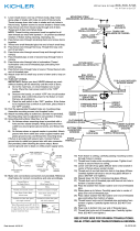
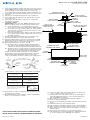
MOUNTING STRAP
ABRAZADERA DE MONTAJE
1) Pass wire from fixture though stem and screw stem to top of
fixture. NOTE: Thread locking compound must be applied to
all stem threads as noted with symbol (3) to prevent
accidental rotation of fixture during cleaning, relamping, etc.
2) Pass fixture wire through remaining stems and screw stems
together.
3) Thread one small threaded pipe into end of small loop.
4) Pass fixture wire through first loop. Thread first loop onto
end of last stem.
5) Pass fixture wire through second loop on canopy and
through hole in canopy.
6) TURN OFF POWER.
IMPORTANT: Before you start, NEVER attempt any work
without shutting off the electricity until the work is done.
a) Go to the main fuse, or circuit breaker, box in your
home. Place the main power switch in the “OFF” position.
b) Unscrew the fuse(s), or switch “OFF” the circuit breaker
switch(s), that control the power to the fixture or room
that you are working on.
c) Place the wall switch in the “OFF” position. If the fixture
to be replaced has a switch or pull chain, place those in
the “OFF” position.
7) Find the appropriate threaded holes on mounting strap.
Assemble mounting screws into threaded holes.
8) Attach mounting strap to outlet box. (Screws not provided).
Mounting strap can be adjusted to suit position of fixture.
9) Attach safety cable to slot in mounting strap.
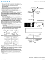
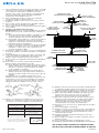
10) Grounding instructions: (See Illus. A or B).
A) On fixtures where mounting strap is provided with a
hole and two raised dimples. Wrap ground wire from
outlet box around green ground screw, and thread into hole.
B) On fixtures where a cupped washer is provided. Attach
ground wire from outlet box under cupped washer and
green ground screw, and thread into mounting strap.
If fixture is provided with ground wire. Connect fixture
ground wire to outlet box ground wire with wire connector.
(Not provided.) After following the above steps. Never
connect ground wire to black or white power supply wires.
11) Make wire connections (connectors not provided.) Reference
chart below for correct connections and wire accordingly.
12) Push fixture to ceiling, carefully passing mounting screws
through holes in canopy.
13) Thread knurl knobs onto mounting screws. Tighten knurl
knobs to secure fixture to ceiling.
GREEN GROUND
SCREW
CUPPED
WASHER
AB
OUTLET BOX
GROUND
FIXTURE
GROUND
DIMPLES
WIRE CONNECTOR
(NOT PROVIDED)
OUTLET BOX
GROUND
GREEN GROUND
SCREW
FIXTURE
GROUND
Connect Black or
Red Supply Wire to:
Connect
White Supply Wire to:
Black White
*Parallel cord (round & smooth) *Parallel cord (square & ridged)
Clear, Brown, Gold or Black
without tracer
Clear, Brown, Gold or Black
with tracer
Insulated wire (other than green)
with copper conductor
Insulated wire (other than green)
with silver conductor
*Note: When parallel wires (SPT I & SPT II)
are used. The neutral wire is square shaped
or ridged and the other wire will be round in
shape or smooth (see illus.) Neutral Wire
Date Issued: 9/4/15 IS-43390-US
CANOPY
ESCUDETE
STEM
VÁSTAGO
KNURL KNOB
PERILLA ESTRADA SMALL LOOP
ARGOLLA PEQUEÑA
SAFETY CABLE
CABLE DE SEGURIDAD
3
SEE OTHER SIDE FOR SPANISH TRANSLATIONS.
VEA EL OTRO LADO DE TRADUCCIONES AL ESPAÑOL.
3
We’re here to help 866-558-5706
Hrs: M-F 9am to 5pm EST
SHADE
PANTALLA
THREADED PIPE
TUBO ROSCADO
FLAT WASHER
ARANDELA PLANA
FLAT WASHER
ARANDELA PLANA
HEXNUT
TUERCA
HEXAGONAL
RUBBER WASHER
ARANDELA DE GOMA
RUBBER WASHER
ARANDELA DE GOMA
BOTTOM TRIM
ADORNO INFERIOR
FINIAL
CAPUCHÓN
DIFFUSER
DIFUSOR
CAGE
JAULA
BALL STUD
PERNO ESFÉRICO
PARA RÓTULA TOP GLASS DIFFUSER
DIFUSOR VIDRIO
14) Lower one half of top glass diffuser down onto bracket in
center of fixture above socket cluster.
15) Thread end of one ball stud into hole in top glass diffuser.
Carefully tighten ball stud to secure top glass diffuser in
place. (DO NOT over tighten.)
16) Repeat steps 13-14 for remaining top glass diffuser.
17) Insert recommended bulbs.
18) Screw end of threaded pipe with bead into bottom of fixture
body.
19) Thread hexnut onto end of threaded pipe.
20) Slip flat washer then rubber washer over end of threaded pipe.
21) Raise shade up to fixture. Fit shade inside cage on fixture.
22) Raise diffuser up to fixture. Pass hole in diffuser over end of
threaded pipe.
22) Pass hole in bottom trim over end of threaded pipe.
23) Thread finial onto end of threaded pipe. Tighten finial finial
to secure shade in place. (DO NOT over tighten.)

1) Pase el alambre del artefacto a través del vástago y atornille
el vástago al tope del artefacto. NOTA: El compuesto para
rosca estanca se debe aplicar a todas las roscas del
vástago como se notó con el símbolo (3) para impedir la
rotación accidental del artefacto durante la limpieza,
instalación de una bombilla nueva, etc.
2) Pase el alambre del artefacto a través de los vástagos
restantes y atornille los vástagos juntos.
3) Atornillar un pequeño tubo roscado en el extremo de lazo
pequeño.
4) Pase el cable a través del primer lazo. Atornillar el primer
lazo en el extremo del vástago de la última.
5) Pase el cable a través del segundo lazo y a través del agujero
en el escudete.
6) APAGUE LA ALIMENTACIÓN ELÉCTRICA.
IMPORTANTE: Antes de comenzar, NUNCA trate de trabajar
sin antes desconectar la corriente hasta que el trabajo se
termine.
a) Vaya a la caja principal de fusibles, o interruptor o caja
de circuitos de su casa. Coloque el interruptor de la
corriente principal en posición de apagado “OFF”.
b) Desatornille el (los) fusible (s), o coloque el interruptor o
interruptores del breaker en posición de apagado
“OFF”, que controla (n) la corriente hacia el artefacto o
habitación donde está trabajando.
c) Coloque el interruptor de pared en posición de apagado
“OFF”. Si el artefacto que se va a reemplazar tiene un
interruptor o cadena que se jala, colóquelos en la
posición de apagado “OFF”.
7) Encontrar los agujeros roscados correctos en la abrazadera
de montaje. Instalar los tornillos de montaje en los agujeros
roscados.
8) Unir la abrazadera de montaje a la caja de conexiones. (No
se proveen tornillos). La abrazadera de montaje puede
ajustarse para acomodar la posición del artefacto.
9) Acople el cable de seguridad en la ranura de la abrazadera
de montaje.
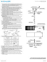
10) Instrucciones de conexión a tierra solamente para los
Estados Unidos. (Vea la ilustracion A o B).
A) En las lámparas que tienen el fleje, de montaje con un
agujero y dos hoyue los realzados. Enrollar el alambre a
tierra de la caja tomacorriente alrededor del tornillo
verde y pasarlo por el aquiero.
B) En las lámparas con una arandela acopada. Fijar el
alambre a tierra de la caja tomacorriente del ajo de la
arandela acoada y tornillo verde, y paser por el fleje de
montaje.
Si la lámpara viene con alambre a tierra. Conecter el
alambre a tierra de la lámpara al alambre a tierra de la caja
tomacorriente con un conector de alambres (no incluido)
espués de seguir los pasos anteriores. Nunca conectar el
alambra a tierra a los alambres eléctros negro o blanco.
11) Haga les conexiones de los alambres (no se proveen los
connectores.) La tabla de referencia de abajo indica las
conexiones correctas y los alambres correspondientes.
Date Issued: 9/4/15 IS-43390-US
ARANDELA
CONCAVA
AB
TIERRA DE LA
CAJA DE SALIDA
TORNILLO DE TIERRA,
VERDE
DEPRESIONES
TIERRA
ARTEFACTO
CONECTOR DE ALAMBRE
(NO SE PROVEE)
TIERRA DE LA
CAJA DE SALIDA
TORNILLO DE TIERRA,
VERDE
TIERRA
ARTEFACTO
Conectar el alambre de
suministro negro o rojo al
Conectar el alambre de
suministro blanco al
Negro Blanco
*Cordon paralelo (redondo y liso) *Cordon paralelo (cuadrado y estriado)
Claro, marrón, amarillio o negro
sin hebra identificadora
Claro, marrón, amarillio o negro
con hebra identificadora
Alambre aislado (diferente del verde)
con conductor de cobre
Alambre aislado (diferente del
verde) con conductor de plata
*Nota: Cuando se utiliza alambre paralelo
(SPT I y SPT II). El alambre neutro es de forma
cuadrada o estriada y el otro alambre será de
forma redonda o lisa. (Vea la ilustracíón). Hilo Neutral
12) Empuje el artefacto hacia el techo, pasando cuidadosamente
los tornillos de montaje a través de los orificios en el escudete.
13) Atornille las perillas estriadas en los tornillos de montaje.
Ajuste las perillas estriadas para fijar el artefacto en el techo.
14) Deslice una de las mitades del difusor de vidrio superior
para que descanse sobre el soporte en el centro del
artefacto, por encima del grupo de portalámparas.
15) Enrosque el extremo de uno de los pernos esféricos para
rótula en el orificio de la difusor de vidrio superior. Ajuste
cuidadosamente el perno esférico para rótula a fin de
asegurar la difusor de vidrio superior en la posición
correspondiente. (no lo ajuste excesivamente).
16) Repita los pasos 14 al 15 con los demás difusores de vidrio
superiores.
17) Inserte la bombilla recomendada.
18) Atornille el extremo corto del tubo roscado con aislador de
cuenta en el acoplamiento en la parte inferior del artefacto.
19) Resbale la arandela plana, luego la arandela de caucho
encima del tubo roscado.
20) Levantar la pantalla a la altura del artefacto. Colocar la
pantalla en la jaula.
21) Pase el agujero en el difusor de vidrio encima del extremo
del tubo roscado.
22) Pase la guarnición inferior encima del tubo roscado
23) Atornille el capuchón al tubo roscado.(NO apriete excesivamente.
SEE OTHER SIDE FOR ENGLISH TRANSLATIONS.
VEA EL OTRO LADO DE TRADUCCIONES AL INGLÉS.
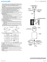
MOUNTING STRAP
ABRAZADERA DE MONTAJE
CANOPY
ESCUDETE
STEM
VÁSTAGO
KNURL KNOB
PERILLA ESTRADA SMALL LOOP
ARGOLLA PEQUEÑA
SAFETY CABLE
CABLE DE SEGURIDAD
3
3
We’re here to help 866-558-5706
Hrs: M-F 9am to 5pm EST
SHADE
PANTALLA
THREADED PIPE
TUBO ROSCADO
FLAT WASHER
ARANDELA PLANA
FLAT WASHER
ARANDELA PLANA
HEXNUT
TUERCA
HEXAGONAL
RUBBER WASHER
ARANDELA DE GOMA
RUBBER WASHER
ARANDELA DE GOMA
BOTTOM TRIM
ADORNO INFERIOR
FINIAL
CAPUCHÓN
DIFFUSER
DIFUSOR
CAGE
JAULA
BALL STUD
PERNO ESFÉRICO
PARA RÓTULA TOP GLASS DIFFUSER
DIFUSOR VIDRIO
-
 1
1
-
 2
2