Kichler Lighting 49933WZC Manual de usuario
- Tipo
- Manual de usuario

Date Issued: 10/13/17 IS-49933-US
We’re here to help 866-558-5706
Hrs: M-F 9am to 5pm EST
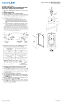
CAUTION – RISK OF SHOCK –
Disconnect Power at the main circuit breaker panel or main fuse
box before starting and during the installation.
1) Take threaded tube[14] and thread on two hexnuts[15] and
thread into main assembly[1] as shown.
2) Place decorative ring[13] on top of main assembly. Next place
top[12] onto the decorative ring as shown and secure into
place using the open nial[11].
3) Take threaded pipe[5] from parts bag and screw in screw
collar loop[9] a minimum of 6 mm (1/4”). Lock into place with
hexnut[6].
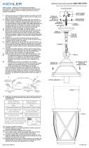
4) Run another hexnut down threaded nipple almost touching
rst hexnut. Now screw threaded pipe into mounting strap[2].
Mounting strap must be positioned with extruded thread faced
into outlet box[4]. Threaded nipple must protrude out the back
of mounting strap. Screw third hexnut onto end of threaded
nipple protruding from back of mounting strap.
5) Connect mounting strap to outlet box using mounting strap
screws[3].
6) Unscrew the threaded ring[8] from screw collar loop. Take
canopy[7] and pass over screw collar loop. Approximately
one half of the screw collar loop exterior threads should be
exposed. Adjust screw collar loop by turning assembly up or
down in mounting strap. Remove canopy.
7) After desired position is found, tighten both top and bottom
hexnuts up against the bottom and top of the mounting strap.
8) Slip canopy over screw collar loop and thread on threaded
ring. Attach chain[10] (with xture connected) to bottom of
screw collar loop. Unscrew threaded ring, let canopy and
threaded ring slip down. Attach chain to xture if required.
9) Weave electrical wire and ground wire through chain links no
more than 3 inches apart. Pass wire through threaded ring,
canopy, screw collar loop, threaded pipe and into outlet box.
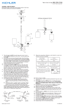
10) Grounding instructions: (See Illus. A or B).
A) On xtures where mounting strap is provided with a
hole and two raised dimples. Wrap ground wire from
outlet box around green ground screw, and thread into
hole.
B) On xtures where a cupped washer is provided. Attach
ground wire from outlet box under cupped washer and
green ground screw, and thread into mounting strap.
If xture is provided with ground wire. Connect xture ground
wire to outlet box ground wire with wire connector. (Not pro-
vided.) After following the above steps. Never connect ground
wire to black or white power supply wires.
11) Make wire connections (connectors not provided.) Reference
chart below for correct connections and wire accordingly.
GREEN GROUND
SCREW
CUPPED
WASHER
OUTLET BOX
GROUND
FIXTURE
GROUND
DIMPLES
WIRE CONNECTOR
OUTLET BOX
GROUND
GREEN GROUND
SCREW
FIXTURE
GROUND
A
B
14
15
13
16
7
2
6
8
9
10
12
5
4
3
11
1
Connect Black or
Red Supply Wire to:
Connect
White Supply Wire to:
Black White
*Parallel cord (round & smooth)
*Parallel cord (square & ridged)
Clear, Brown, Gold or Black
without tracer
Clear, Brown, Gold or Black
with tracer
Insulated wire (other than green)
with copper conductor
Insulated wire (other than green)
with silver conductor
*Note: When parallel wires (SPT I & SPT II)
are used. The neutral wire is square shaped
or ridged and the other wire will be round in
shape or smooth (see illus.)
Neutral Wire
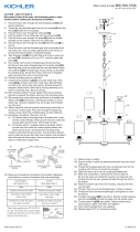
12) Raise canopy to ceiling.
13) Secure canopy in place by tightening threaded ring onto screw
collar loop.
14) Install glass[16] by sliding up from the bottom of glass cage
and seat into the inside bottom of cage as shown. Next bend
over the tabs above the glass to secure into place. Repeat for
all the glass panels.
15) Insert recommended bulb (Not supplied).

Estamos aquí para ayudarle 866-558-5706
Horario: Lunes-Viernes 9am a 5pm EST (hora ocial del este)
PRECAUCIÓN – RIESGO DE DESCARGA ELÉCTRICA –
Desconecte la electricidad en el panel principal del interruptor
automático o caja principal de fusibles antes de comenzar y
durante la instalación.
Date Issued: 10/13/17 IS-49933-US
1) Tome el tubo roscado[14] e insértelo en dos hexágonos[15] y
enrosque en el ensamblaje principal[1] como se muestra.
2) Coloque el anillo decorativo[13] en la parte superior del
conjunto principal. Coloque la parte superior[12] en el anillo
decorativo como se muestra y asegúrelo en su lugar con el
remate abierto[11].
3) Tome la tubería roscada[5] de la bolsa de piezas y atornille
el collarín lazo[9] un mínimo de 6 mm (1/4"). Asegúrelo en su
lugar con hexágono[6].
4) Ejecuta otra tubería hexagonal con rosca hacia abajo casi
tocando la primera hexágono. Ahora atornille la tubería
roscada en la correa de montaje[2]. La correa de montaje
debe colocarse con el hilo extruido hacia la caja de salida[4].
La tubería roscada debe sobresalir por la parte posterior de la
correa de montaje. Atornille el tercer hexágono en el extremo
de la tubería roscada que sobresale de la parte posterior de la
correa de montaje.
5) Conecte la correa de montaje a la caja de salida[3].
6) Desenrosque el anillo roscado[8] del anillo del collar roscado.
Tome el dosel[7] y pase sobre el anillo del cuello del tornillo.
Aproximadamente la mitad de las roscas exteriores del lazo
del collar de tornillo deben estar expuestas. Ajuste el aro del
collar de tornillo girando el conjunto hacia arriba o hacia abajo
en la correa de montaje. Eliminar el dosel.
7) Después de encontrar la posición deseada, apriete las tuercas
hexagonal superior e inferior contra la parte inferior y superior
de la correa de montaje.
8) Deslizar el dosel sobre el anillo del collar de tornillo y roscar
en roscado anillo. Conecte la cadena[10] (con el accesorio
conectado) a la parte inferior de la atornillar el lazo del collar.
Desenrosque el anillo roscado, el anillo roscado se desliza
hacia abajo. Si es necesario, conecte la cadena al accesorio.
9) Armadura de cable eléctrico y cable a tierra a través de la
cadena de enlaces separados no más de 3 pulgadas. Pasar
el alambre a través del dosel, lazo del collar del tornillo, anillo
roscado, tubo roscado y en caja de salida.
10) Instrucciones de conexión a tierra de: (ver Fig. A o B)
A) En artefactos donde se suministra la abrazadera de
montaje con un agujero y dos depresiones onduladas.
Envuelva el conductor de tierra de la caja de salida
alrededor del tornillo de tierra verde y atornille en el
agujero.
B) En artefactos donde se suministra una arandela
cóncava. Fije el conductor de tierra de la caja de salida
debajo de la arandela cóncava y el tornillo de tierra
verde y enrosque en la abrazadera de montaje.
Si se suministra el artefacto con conductor de tierra. Conecte
el conductor de tierra del artefacto al conductor de tierra de
la caja de salida con conector de tierra después de seguir los
pasos anteriores. Nunca conecte el conductor de tierra a los
alambres de alimentación eléctrica negros o blancos.
11) Haga les conexiones de los alambres. La tabla de referencia
de abajo indica las conexiones correctas y los alambres cor-
respondientes.
ARANDELA
CONCAVA
TIERRA DE LA
CAJA DE SALIDA
TORNILLO DE TIERRA,
VERDE
DEPRESIONES
TIERRA
ARTEFACTO
CONECTOR DE ALAMBRE
TIERRA DE LA
CAJA DE SALIDA
TORNILLO DE TIERRA,
VERDE
TIERRA
ARTEFACTO
A
B
14
15
13
16
7
2
6
8
9
10
12
5
4
3
11
1
12) Levante el pabellón al techo.
13) Pabellón segura en su lugar apretando el anillo roscado al lazo
del collar del tornillo.
14) Instale el vidrio[16] deslizando hacia arriba desde la parte
inferior de la jaula de vidrio y asiente en el interior de la parte
inferior de la jaula, como se muestra. Luego, dobla sobre las
lengüetas sobre el cristal para asegurarte en su lugar. Repita
para todos los paneles de vidrio.
15) Inserte la bombilla recomendada (no suministrada).
Conectar el alambre de
suministro negro o rojo al
Conectar el alambre de
suministro blanco al
Negro Blanco
*Cordon paralelo (redondo y liso)
*Cordon paralelo (cuadrado y
estriado)
Claro, marrón, amarillio o negro
sin hebra identificadora
Claro, marrón, amarillio o negro
con hebra identificadora
Alambre aislado (diferente del
verde) con conductor de cobre
Alambre aislado (diferente del
verde) con conductor de plata
*Nota: Cuando se utiliza alambre paralelo
(SPT I y SPT II). El alambre neutro es de forma
cuadrada o estriada y el otro alambre será de
forma redonda o lisa. (Vea la ilustracíón).
Hilo Neutral
-
 1
1
-
 2
2


Kichler Lighting 49933WZC Manual de usuario
- Tipo
- Manual de usuario
en otros idiomas
Artículos relacionados
-
 Kichler Lighting 49934WZC Manual de usuario
-
 Kichler Lighting 43984BK Manual de usuario
-
 Kichler Lighting 49844OZ Manual de usuario
-
 Kichler Lighting 49875WZC Manual de usuario
-
 Kichler Lighting 44030NI Manual de usuario
-
Kichler Lighting 49931WZC Manual de usuario
-
 Kichler Lighting 49931WZC Manual de usuario
-
 Kichler Lighting 44311PN Manual de usuario
-
Kichler Lighting 5096NI Manual de usuario
-
 Kichler Lighting 44031NI Manual de usuario


