CJ Spray 966 Instrucciones de operación
- Categoría
- Rociador de pintura
- Tipo
- Instrucciones de operación
Este manual también es adecuado para

- For portable spray application of architectural paints and coatings -
- Pour l’application de peintures et revêtements architecturaux avec un appreil mobile -
- Para aplicaciones de pulverización portátiles de pinturas y revestimientos con fines arquitectónicos -
190ES Model: 261825 / 210ES Model: 261830
Maximum Working Pressure: 3000 psi (20.7 MPa, 207 bar)
Important Safety Instructions
Read all warnings and instructions in
this manual. Save these instructions.
Instructions de sécurité importantes
Lire toutes les mises en garde et instructions
de ce manuel. Sauvegarder ces intructions.
Instrucciones importantes de seguridad
lea todas las advertencias e instrucciones
de este manual. Guarde las instructionnes.
Related Manuals
311990
312830
English
312831
Français
312832
Español
312015
311988C
Operation
190ES/210ES™ Electric Airless Sprayer
Pulvérisateurs électriques Airless 190ES/210ES™
Pulverizadores eléctricos sin aire 190ES/210ES™
ti16975a
ENG FRA SPA

Warning
2311988C
Warning
The following warnings are for the setup, use, grounding, maintenance, and repair of this equipment. The exclama-
tion point symbol alerts you to a general warning and the hazard symbol refers to procedure-specific risk. Refer back
to these warnings. Additional, product-specific warnings may be found throughout the body of this manual where
applicable.
WARNING
FIRE AND EXPLOSION HAZARD
Flammable fumes, such as solvent and paint fumes, in work area can ignite or explode. To help prevent
fire and explosion:
• Use equipment only in well ventilated area.
• Eliminate all ignition sources; such as pilot lights, cigarettes, portable electric lamps, and plastic drop
cloths (potential static arc).
• Sprayer generates sparks. When flammable liquid is used in or near the sprayer or for flushing or
cleaning, keep sprayer at least 20 feet (6 m) away from explosive vapors.
• Keep work area free of debris, including solvent, rags and gasoline.
• Do not plug or unplug power cords or turn lights on or off when flammable fumes are present.
• Ground equipment and conductive objects in work area. Read Grounding instructions.
• If there is static sparking or you feel a shock, stop operation immediately. Do not use equipment
until you identify and correct the problem.
• Keep a working fire extinguisher in the work area.
ELECTRIC SHOCK HAZARD
Improper grounding, setup, or usage of the system can cause electric shock.
• Turn off and disconnect power cord before servicing equipment.
• Use only grounded electrical outlets.
• Use only 3-wire extension cords.
• Ensure ground prongs are intact on sprayer and extension cords.
• Do not expose to rain. Store indoors.
SKIN INJECTION HAZARD
High-pressure fluid from gun, hose leaks, or ruptured components will pierce skin. This may look like just
a cut, but it is a serious injury that can result in amputation. Get immediate surgical treatment.
• Do not point gun at anyone or at any part of the body.
• Do not put your hand over the spray tip.
• Do not stop or deflect leaks with your hand, body, glove, or rag.
• Engage trigger lock when not spraying.
• Follow Pressure Relief Procedure in this manual, when you stop spraying and before cleaning,
checking, or servicing equipment.

Warning
311988C 3
WARNING
EQUIPMENT MISUSE HAZARD
Misuse can cause death or serious injury.
• Do not exceed the maximum working pressure or temperature rating of the lowest rated system
component. Read Technical Data in all equipment manuals.
• Use fluids and solvents that are compatible with equipment wetted parts. Read Technical Data in all
equipment manuals. Read fluid and solvent manufacturer’s warnings. For complete information
about your material, request MSDS from distributor or retailer.
• Check equipment daily. Repair or replace worn or damaged parts immediately with genuine Graco
replacement parts only.
• Do not alter or modify equipment.
• Use equipment only for its intended purpose. Call your Graco distributor for information.
• Route hoses and cables away from traffic areas, sharp edges, moving parts, and hot surfaces.
• Do not kink or overbend hoses or use hoses to pull equipment.
• Keep children and animals away from work area.
• Comply with all applicable safety regulations.
• Do not operate the equipment when fatigued or under the influence of drugs or alcohol.
PRESSURIZED ALUMINUM PARTS HAZARD
Do not use 1,1,1-trichloroethane, methylene chloride, other halogenated hydrocarbon solvents or fluids
containing such solvents in pressurized aluminum equipment. Such use can cause serious chemical
reaction and equipment rupture, and result in death, serious injury, and property damage.
TOXIC FLUID OR FUMES HAZARD
Toxic fluids or fumes can cause serious injury or death if splashed in the eyes or on skin, inhaled, or
swallowed.
• Read MSDS’s to know the specific hazards of the fluids you are using.
• Store hazardous fluid in approved containers, and dispose of it according to applicable guidelines.
PERSONAL PROTECTIVE EQUIPMENT
You must wear appropriate protective equipment when operating, servicing, or when in the operating
area of the equipment to help protect you from serious injury, including eye injury, inhalation of toxic
fumes, burns, and hearing loss. This equipment includes but is not limited to:
• Protective eye wear
• Clothing and respirator as recommended by the fluid and solvent manufacturer
•Gloves
• Hearing protection

Mise en garde
4311988C
Mise en garde
Les mises en gardes suivantes sont des mises en garde de sécurité relatives à la configuration, utilisation, mise à la
terre, maintenance et réparation de ce matériel. D’autres mises en garde plus spécifiques figurent dans ce manuel
aux endroits concernés. Les symboles figurant dans ce manuel font référence à ces mises en garde générales.
Quand vous voyez l’un de ces symboles dans le manuel, reportez-vous à ces pages où ce risque spécifique est
décrit.
MISE EN GARDE
DANGERS D’INCENDIE ET D’EXPLOSION
Les vapeurs inflammables de solvant et de peinture sur le lieu de travail peuvent prendre feu ou exploser.
Pour prévenir un incendie ou une explosion:
• N’utiliser l’équipement que dans des locaux bien ventilés.
• Supprimer toutes les source de feu, telles que les veilleuses, cigarettes, lampes électriques porta-
tives et bâches plastique (risque de décharge d’électricité statique).
• Les pulvérisateurs produisent des étincelles. En cas d’utilisation de liquides inflammables dans
ou près du pulvérisateur ou encore pour rincer ou nettoyer, tenir le pulvérisateur à un minimum
de 20 pieds (6 m) des vapeurs explosives.
• Veiller à débarrasser la zone de travail de tout résidu, comme les solvants, les chiffons et l’essence.
• Ne pas brancher ni débrancher de cordons d’alimentation électrique ni actionner de commutateur
marche-arrêt ou de lumière en présence de vapeurs inflammables.
• Raccorder à la terre le matériel et les objets conducteurs du site. Voir les instructions de Mise
àlaterre.
• Si l’on remarque la moindre étincelle d’électricité statique ou si l’on ressent une décharge électrique,
arrêter le travail immédiatement. Ne pas utiliser le matériel tant que le problème n’a pas été identi-
fié et résolu.
• La présence d’un extincteur est obligatoire dans la zone de travail.
DANGER DE DÉCHARGE ÉLECTRIQUE
Une mauvaise mise à la terre, un mauvais réglage ou une mauvaise utilisation du système peut provo-
quer une décharge électrique.
• Mettre hors tension et débrancher le câble d’alimentation avant de procéder à un entretien du
matériel.
• N’utiliser que des prises électriques reliées à la terre.
• N’utiliser que des rallonges à 3 conducteurs.
• S’assurer que les fiches de terre du pulvérisateur et des rallonges sont intactes.
• Ne pas exposer à la pluie. Entreposer à l’intérieur.
DANGERS D’INJECTIONS
Le produit s’échappant à haute pression du pistolet, d’une fuite sur le flexible ou d’un composant
défectueux risque de transpercer la peau. La blessure peut avoir l’aspect d’une simple coupure, mais il
s’agit en fait d’une blessure sérieuse pouvant entraîner une amputation. Consulter immédiatement un
médecin en vue d’une intervention chirurgicale.
• Ne pas diriger le pistolet sur quelqu’un ou une partie quelconque du corps.
• Ne pas mettre la main devant la buse de pulvérisation.
• Ne jamais colmater ou dévier les fuites avec la main, le corps, un gant ou un chiffon.
• Ne pas pulvériser sans garde-buse ni sous-garde.
• Verrouiller la gâchette à chaque arrêt de la pulvérisation.
• Suivre la Procédure de décompression de ce manuel à chaque interruption de la pulvérisation et
avant le nettoyage, la vérification ou l’entretien du matériel.

Mise en garde
311988C 5
MISE EN GARDE
DANGER EN CAS DE MAUVAISE UTILISATION DE L’ÉQUIPEMENT
Toute mauvaise utilisation du matériel peut provoquer des blessures graves, voire mortelles.
• Ne pas dépasser la pression ou température de service maximum spécifiée de l’élément le plus
faible du système. Voir les Caractéristiques techniques de tous les manuels de l’appareil.
• Utiliser des produits et solvants compatibles avec les pièces en contact avec le produit. Voir les
Caractéristiques techniques de tous les manuels d’équipement. Pour plus d’informations sur votre
produit, demandez la fiche de sécurité produits à votre distributeur ou revendeur.
• Vérifier l’équipement tous les jours. Réparer ou remplacer immédiatement les pièces usées ou
endommagées par des pièces de rechange d’origine Graco.
• Ne pas modifier cet équipement.
• N’utiliser ce matériel que pour l’usage auquel il est destiné. Pour plus de renseignements appelez
votre distributeur Graco.
• Écarter les flexibles et câbles électriques des zones de circulation, des bords coupants, des pièces
en mouvement et des surfaces chaudes.
• Ne pas plier ni trop cintrer les flexibles ni les utiliser pour tirer l’appareil.
• Se conformer à toutes les règles de sécurité applicables.
• Tenir les enfants et animaux à l’écart du site de travail.
• Ne pas utiliser l’appareil si l’on est fatigué ou sous l’influence de drogue ou d’alcool.
RISQUES DUS AUX PIÈCES EN ALUMINIUM SOUS PRESSION
N’utiliser ni 1,1,1-trichloréthane, ni chlorure de méthylène, ni solvants à base d’hydrocarbures halogénés,
ni produits renfermant de tels solvants dans un appareil sous pression en aluminium. L’utilisation de ces
produit peut déclencher une violente réaction chimique et une casse du matériel et provoquer ainsi de
graves dommages corporels et matériels pouvant entraîner la mort.
DANGERS PRESENTES PAR LES PRODUITS OU VAPEURS TOXIQUES
Les produits ou vapeurs toxiques peuvent causer de graves blessures et entraîner la mort en cas de
projection dans les yeux ou sur la peau, en cas d’inhalation ou d’ingestion.
• Lire la fiche de sécurité produit (MSDS) pour prendre connaissance des risques spécifiques aux
produits utilisés.
• Stocker les produits dangereux dans des récipients homologués et les éliminer conformément
à la réglementation en vigueur.
EQUIPEMENT DE PROTECTION DU PERSONNEL
Il est impératif que le personnel porte un équipement de protection approprié quand il travaille ou se
trouve dans la zone de fonctionnement de l’installation pour éviter des blessures graves telles que des
lésions oculaires, inhalation de fumées toxiques, brûlures et perte de l’ouïe notamment. Cet équipement
comprend ce qui suit, la liste n’étant pas exhaustive:
• Lunettes de sécurité
• Le port de vêtements de sécurité et d’un respirateur est conseillé par le fabricant de produit
et de solvant
•Gants
• Casque anti-bruit

Advertencias
6311988C
Advertencias
A continuación se ofrecen advertencias en general relacionadas con la seguridad de la puesta en marcha, utilización,
conexión a tierra, mantenimiento y reparación de este equipo. Además, puede encontrar advertencias adicionales a
lo largo de este manual siempre que sea pertinente. Los símbolos que aparecen en el texto del manual se refieren a
estas advertencias generales. Cuando vea estos símbolos en el manual, consulte estas páginas para obtener una
descripción del riesgo específico.
ADVERTENCIAS
PELIGRO DE INCENDIOS Y EXPLOSIONES
Los vapores inflamables, como los vapores de disolvente o de pintura, en la zona de trabajo pueden
incendiarse o explotar. Para evitar un incendio o explosión:
• Utilice el equipo únicamente en áreas bien ventiladas.
• Elimine toda fuente de ignición, tales como las luces piloto, los cigarrillos, las linternas eléctricas
y las cubiertas de plástico (arcos estáticos potenciales).
• El pulverizador genera chispas. Cuando utilice líquidos inflamables cerca de, o en el pulverizador,
o cuando lo lave o limpie, mantenga el pulverizador al menos a 6 m (20 pies) de distancia de los
vapores explosivos.
• Mantenga limpia la zona de trabajo, sin disolventes, trapos o gasolina.
• No enchufe ni desenchufe cables de alimentación ni apague ni encienda las luces en el área de
pulverización.
• Conecte a tierra el equipo y los objetos conductores de la zona de trabajo. Vea las instrucciones
de Conexión a tierra.
• Si se aprecia la formación de electricidad estática durante el uso de este equipo, deje de trabajar
inmediatamente. No utilice el sistema hasta haber identificado y corregido el problema.
• Guarde un extintor de incendios en la zona de trabajo.
PELIGRO DE DESCARGA ELÉCTRICA
Una conexión a tierra, montaje o utilización incorrectos del sistema puede causar descargas eléctricas.
• Apague y desconecte la alimentación eléctrica antes de desconectar el equipo.
• Utilice únicamente tomas eléctricas conectadas a tierra.
• Utilice únicamente cables de extensión de 3 hilos.
• Compruebe que los terminales de conexión a tierra del pulverizador y de los cables de extensión
están intactas.
• Proteja de la lluvia. Guárdelo en un recinto cerrado.
PELIGRO DE INYECCIÓN A TRAVÉS DE LA PIEL
El fluido a alta presión procedente de la pistola, fugas de la manguera o componentes rotos penetrarán
en la piel. La inyección del líquido puede tener la apariencia de un simple corte, pero se trata de una
herida grave que puede conducir a la amputación. Consiga inmediatamente tratamiento quirúrgico.
• No apunte nunca la pistola hacia alguien o alguna parte del cuerpo.
• No coloque la mano sobre la boquilla de pulverización.
• No intente bloquear ni desviar posibles fugas con la mano, el cuerpo, los guantes o con un trapo.
• No pulverice sin el portaboquillas y el seguro del gatillo.
• Enganche el seguro del gatillo cuando no esté pulverizando.
• Siga el Procedimiento de descompresión de este manual, cuando deje de pulverizar y antes de
limpiar, revisar o reparar el equipo.

Advertencias
311988C 7
ADVERTENCIAS
PELIGROS DEBIDOS A LA UTILIZACIÓN INCORRECTA DEL EQUIPO
El uso incorrecto puede causar la muerte o heridas graves.
• No exceda la presión máxima de trabajo o la temperatura del componente con menor valor nominal
del sistema. Consulte la sección Características técnicas de todos los manuales del equipo.
• Utilice líquidos y disolventes compatibles con las piezas húmedas del equipo. Consulte las Carac-
terísticas técnicas en todos los manuales que acompañan al equipo. Para obtener información
completa sobre su material, pida la MSDS al distribuidor o al minorista.
• Revise el equipo a diario. Repare o cambie inmediatamente las piezas desgastadas o deterioradas
únicamente con piezas de repuesto genuinas de Graco.
• No altere ni modifique el equipo.
• Utilice el equipo únicamente para el fin para el que ha sido destinado. Si desea información, póngase
en contacto con su distribuidor Graco.
• Desvíe las mangueras de zonas de tráfico intenso, de curvas pronunciadas, de piezas movibles
y superficies calientes.
• No retuerza ni doble las mangueras, ni las utilice para arrastrar el equipo.
• Respete todas las normas relativas a la seguridad.
• Mantenga a los niños y a los animales lejos de la zona de trabajo.
• No utilice el equipo si está cansado o bajo los efectos de medicamentos o del alcohol.
PELIGRO DE PIEZAS DE ALUMINIO A PRESIÓN
No utilice 1,1,1 tricloroetano, cloruro de metileno y otros disolventes de hidrocarburos halogenados
o productos que contengan dichos disolventes con equipos de aluminio presurizados. Esas sustancias
podrían provocar peligrosas reacciones químicas y ruptura del equipo, y causar la muerte, lesiones
graves y daños materiales.
PELIGRO DE VAPORES O LÍQUIDOS TÓXICOS
Los líquidos o los vapores tóxicos pueden provocar serios daños o incluso la muerte si entran en
contacto con los ojos o la piel, se inhalan o se ingieren.
• Lea la Hoja de datos de seguridad del material (MSDS) para conocer los peligros específicos
de los líquidos que esté utilizando.
• Guarde los fluidos peligrosos en un envase adecuado que haya sido aprobado. Proceda a su
evacuación siguiendo las directrices pertinentes.
EQUIPO DE PROTECCIÓN PERSONAL
Debe utilizar equipo de protección adecuado cuando trabaje, revise o esté en la zona de funcionamiento
del equipo, con el fin de protegerse contra la posibilidad de lesionarse gravemente, incluyendo lesiones
oculares, la inhalación de vapores tóxicos, quemaduras o la pérdida auditiva. Este equipo incluye, pero
no está limitado a:
• Gafas de protección
• Ropas protectoras y un respirador, tal como recomiendan los fabricantes del fluido y del disolvente
• Guantes
• Protección auditiva

Component Identification / Identification des composants / Identificación de los componentes
8311988C
Component Identification / Identification des composants / Identificación de los componentes
T
J
H
E
A
B
G
F
DK
M
N
S
PR
U
ti9033a
ti9034a
V
W
X
English Français Español
APressure Control Régulation
de pression Control de la presión
BON/OFF switch Bouton MARCHE/ARRÊT Interruptor de encendido/apagado
DPower Cord Cordon électrique Cable de alimentación
EFluid Outlet Sortie produit Salida de fluido
FPrime Valve Vanne d’amorçage Válvula de cebado
GKick Stand (210ES Series A) Support de coup-de-pied (210 ES Serie A) Soporte del retroceso (210 ES Serie A)
HPump Pompe Bomba
JSuction Tube Tube d’aspiration Tubo de aspiración
KDrain Hose Flexible de vidange Manguera de drenaje
MFluid Hose Flexible produit Manguera de fluido
NGun Pistolet Pistola
PTip Buse Boquilla
RGuard Garde Portaboquillas
STrigger Safety Lock Verrou de sécurité de la gâchette Cierre de seguridad del gatillo
TSerial Number ID Label
Étiquette d’identification avec numéro de série
Etiqueta de identificación del número de serie
UFilter Cap Capot du filtre Tapa del filtro
VPail Hook Systeme d’accrochage du seau Colgador para el bidón
WPower Flush Adapter Raccord de rinçage forcé Acoplamiento de la lavado eléctrico
XShutoff Valve la robinet d'arrete La válvula de cierre

Pressure Relief Procedure / Procédure de décompression / Procedimiento de descompresión
311988C 9
Pressure Relief Procedure /
Procédure de décompression /
Procedimiento de descompresión
English Français Español
Follow this Pressure Relief Procedure whenever you
stop spraying and before cleaning, checking, servic-
ing, or transporting equipment.
Observer cette Procédure de décompression, à
chaque arrêt de la pulvérisation et avant tout nettoy-
age, contrôle, entretien ou manutention du matériel.
Siga el Procedimiento de descompresión, cuando
deje de pulverizar y antes de limpiar, revisar, reparar
o transportar el equipo.
English
1 Turn pressure control to lowest
pressure. 2 Hold gun against side of grounded
metal flushing pail. Trigger gun to
relieve pressure.
3 Turn prime valve down.
If you suspect spray tip or hose is clogged
or pressure is not fully relieved, VERY
SLOWLY loosen tip guard retaining nut or
hose end coupling to relieve pressure.
Then loosen completely.
4 Turn power switch OFF, if unit is
being shut down or will be left unat-
tended.
Français
1 Régler la régulation de pression
au niveau le plus bas. 2 Appuyer le pistolet contre la paroi
d’un seau de rinçage métallique mis
à la terre. Actionner le pistolet pour
relâcher la pression.
3 Tourner la vanne d’amorçage vers le bas.
Si vous pensez que la buse de pulvérisation
ou le flexible est bouché ou que la pression
n’a pas été complètement relâchée après les
opérations ci-dessus, desserrer TRÈS
LENTEMENT l’écrou de fixation du garde-
buse ou le raccord du flexible pour relâcher
la pression, puis desserrer complètement.
4 Mettre le commutateur M/A sur
ARRÊT pour arrêter l’appareil ou
si on le laisse sans surveillance.
Español
1 Ajuste el dispositivo de control
de presión al valor más bajo. 2 Mantenga la pistola contra el lateral
de una lata metálica de lavado
conectada a tierra. Dispare la pis-
tola para aliviar la presión.
3 Gire la válvula de cebado hacia abajo.
Si se sospecha que la boquilla de pulver-
ización o la manguera están obstruidas, o
que no se ha liberado completamente la
presión, afloje MUY LENTAMENTE la
tuerca de retención del portaboquillas o el
acoplamiento del extremo de la manguera
para liberar la presión. Después afloje com-
pletamente.
4 Apague el interruptor de potencia,
si desea apagar la unidad o la va
a dejar desatendida.
ti8324a ti9035a
ti8326a
ti5316b
ON
OFF

Grounding / Mise à la terre / Conexión a tierra
10 311988C
Grounding / Mise à la terre / Conexión a tierra
English Français Español
The sprayer must be grounded. Grounding
reduces the risk of static and electric shock
by providing an escape wire for the electrical
current due to static build up or in the event of
a short circuit.
Ce pulvérisateur doit être raccordé à la terre.
La mise à la terre réduit les risques
d’électricité statique et de décharge électrique
grâce à un fil permettant au courant
de s’échapper en cas d’accumulation d’élec-
tricité statique ou de court-circuit.
Este pulverizador debe estar conectado a tier-
ra. La conexión a tierra reduce el riesgo de
descargas eléctricas y estáticas al proporcio-
nar un cable por donde puede escapar la cor-
riente eléctrica debida a la acumulación
estática o en caso de que haya un cortocircu-
ito.
English
• The sprayer cord includes a grounding wire with an appropriate grounding
contact. • The plug must be plugged into an
outlet that is properly installed and
grounded in accordance with all
local codes and ordinances.
• Do not modify plug! If it will not fit
in outlet, have grounded outlet
installed by a qualified electri-
cian. Do not use an adapter.
Français
• Le cordon d’alimentation possède un fil de terre relié à un contact de mise à
la terre approprié. • Cette fiche doit être enfichée dans
une prise montée et reliée à la terre
conformément à la réglementation
locale.
• Ne pas modifier le connecteur!
S’il ne rentre pas dans la prise,
faire installer une prise avec
mise à la terre par un électricien
qualifié. Ne pas utiliser d’adapta-
teur.
Español
• El cable del pulverizador incluye un hilo de conexión a tierra con el contacto
de conexión a tierra adecuado. • La clavija debe estar enchufada en
una toma correctamente instalada
y conectada a tierra de acuerdo
con los códigos y decretos locales.
• ¡No modifique la clavija suminis-
trada! Si no encaja en la toma
eléctrica, pida a un electricista
cualificado que instale una toma
de corriente conectada a tierra.
No utilice un adaptador.
TIA
ti4297a

Grounding / Mise à la terre / Conexión a tierra
311988C 11
English Power Requirements Extension Cords
• 120V units require
100 - 120 Vac, 60 Hz, 11A, 1
phase.
• Use an extension cord with an
undamaged ground contact.
• If an extension cord is necessary,
use a 3-wire, 12 AWG (2.5 mm2)
minimum.
Français Spécification électrique Rallonges
• Les appareils de 120V
fonctionnent en 100 - 120 Vca,
60 Hz, 11A, 1 phase.
• Utiliser un cordon d’alimentation
électrique muni d’un contact de
mise à la terre en bon état.
• Si une rallonge est nécessaire,
utiliser un fil à 3 conducteurs, de
12 AWG (2,5 mm2) minimum.
Español Requisitos eléctricos Cables de extensión
• 120V requieren 100 - 120 Vca,
60 Hz, 11A, monofásico.
• Utilice un cable de extensión con
un contacto en buen estado.
• Si fuera necesario utilizar un
cable de extensión, utilice un
cable de 3 hilos, 12 AWG
(2,5 mm2) como mínimo.
120 volt plug
ground

Grounding / Mise à la terre / Conexión a tierra
12 311988C
English Pails
•Solvent and oil/based fluids:
follow local code. Use only con-
ductive metal pails, placed on
a grounded surface such as
concrete.
• Do not place pail on a nonconduc-
tive surface such as paper or card-
board which interrupts grounding
continuity.
•Grounding a metal pail: connect a
ground wire to the pail by clamping
one end to pail and other end to a
true earth ground such as a metal
water pipe.
•To maintain grounding con-
tinuity when flushing or
relieving pressure: hold metal
part of spray gun firmly to side
of a grounded metal pail. Then
trigger gun.
Français Seaux
•Solvants et fluides à l’huile/à
l’eau: Respecter la réglementation
locale. N’utiliser que des seaux
métalliques conducteurs placés
sur une surface reliée à la terre,
sur du béton par exemple.
• Ne pas poser le seau sur une sur-
face non conductrice telle que du
papier ou du carton car cela aurait
pour effet d’interrompre la continu-
ité de la mise à la terre.
•Mise à la terre du seau métal-
lique: brancher un fil de terre sur le
seau en pinçant une extrémité sur
le seau et l’autre sur une véritable
terre, comme une conduite d’eau
en métal par exemple.
•Pour maintenir la continuité de
la mise à la terre pendant le
rinçage ou la décompression:
appuyer une partie métallique du
pistolet contre le côté d’un seau
métallique relié à la terre, puis
appuyer sur la gâchette du
pistolet.
Español Bidones
•Disolvente y fluidos a base de
aceite: de acuerdo con las normas
locales. Utilice sólo latas metálicas
conductoras, colocadas sobre una
superficie de tipo cemento.
• No coloque el bidón sobre una
superficie no conductora, como
papel o cartón, que pueda
interrumpir la continuidad de
la conexión a tierra.
•Conexión a tierra del bidón
metálico: conecte un cable de
conexión a tierra al bidón sujetando
un extremo al bidón y el otro
extremo a una tierra verdadera,
por ej. una tubería de agua del
metal.
•Para mantener la continuidad
de la puesta a tierra durante la
limpieza o la liberación de la
presión: sujete firmemente una
pieza metálica de la pistola de
pulverización contra el borde de
una lata metálica con conexión
a tierra. Después dispare la
pistola.
ti5850a ti5851a
ti9035a

Setup / Installation / Configuración
311988C 13
Setup / Installation / Configuración
English
1 Connect Graco airless hose
to sprayer.
Tighten securely.
2 Connect other end of hose
to gun.
3 Tighten securely. 4 Remove tip guard.
Français
1 Brancher un flexible Graco
type airless sur le pulvérisa-
teur.
Bien serrer.
2 Brancher l’autre extrémité
du flexible sur le pistolet.
3 Bien serrer. 4 Retirer le garde-buse.
Español
1 Conecte la manguera sin
aire Graco al pulverizador.
Apriete firmemente.
2 Conecte el otro extremo
de la manguera a la pistola.
3 Apriete firmemente. 4 Retire el portaboquillas.
ti9036a ti9037a ti9038a ti9039a

Setup / Installation / Configuración
14 311988C
English
5 Check inlet strainer for clogs
and debris.
6 Fill throat packing nut with
TSL to prevent premature
packing wear.
Do this each time you spray.
7 Turn power OFF. 8 Plug power supply cord
into a properly grounded
electrical outlet.
Français
5 Vérifier si la crépine d’entrée
est bouchée ou contient des
impuretés.
6 Remplir l’écrou du presse-
étoupe de liquide TSL
pour empêcher une usure
prématurée.
Le faire à chaque pulvérisa-
tion.
7 COUPER l’alimentation
électrique.
8 Brancher le cordon d’ali-
mentation sur une prise
électrique correctement
raccordée à la terre.
Español
5 Revise el elemento filtrante
de entrada en busca de
obstrucciones o suciedad.
6 Llene la tuerca prensaesto-
pas del cuello con TSL
para evitar el desgaste
prematuro de las empa-
quetaduras.
Haga esto cada vez que uti-
lice el pulverizador.
7 Apague el suministro
de energía.
8 Enchufe el cable de alimen-
tación eléctrica a una toma
eléctrica con conexión
a tierra.
ti5301a ti9040a
ti5316b
ON
OFF
TIA

Setup / Installation / Configuración
311988C 15
English
9 Turn prime valve down. 10 Place siphon tube set in grounded metal pail partially filled with flushing fluid. See Grounding,
page 10. Do steps 1- 6 of Startup, page 16, to flush out storage oil shipped in sprayer. Use water to
flush water-based paint or mineral spirits to flush oil-based paint and storage oil.
Français
9 Tourner la vanne d’amor-
çage vers le bas.
10 Plonger le tuyau d’aspiration dans un seau métallique mis à la terre rempli partiellement de fluide de
rinçage. Voir Mise à la terre, page 10. Effectuer les opérations 1- 6 du Démarrage, page 16, pour
purger l’huile de stockage contenue dans le pulvérisateur. Utiliser de l’eau pour purger les peintures
à l’eau et du white spirit pour les peintures à l’huile et l’huile de stockage.
Español
9 Gire la válvula de cebado
hacia abajo.
10 Coloque el conjunto de tubos de aspiración en un recipiente metálico conectado a tierra y parcial-
mente lleno con líquido de lavado. Vea Conexión a tierra, página 10. Realice los pasos 1- 6 de la
Puesta en marcha, página 16, para eliminar el aceite de almacenamiento que se envía con el pulveri-
zador. Utilice agua para eliminar las pinturas acuosas y alcoholes minerales para las pinturas a base
de aceite y el aceite de almacenamiento.
ti8326a
ti9041a
Flush

Startup / Démarrage / Puesta en marcha
16 311988C
Startup / Démarrage / Puesta en marcha
English
1 Turn pressure control to
lowest pressure.
2 Turn power ON. 3 Increase pressure 1/4 turn
to start motor. Allow fluid
to circulate through drain
tube for 15 seconds.
4 Turn prime valve horizon-
tal.Take spray gun trigger
safety OFF.
Français
1 Régler la régulation de pres-
sion au niveau le plus bas.
2 Mettre en MARCHE. 3 Augmenter la pression de
1/4 de tour pour démarrer le
moteur. Faire circuler le
produit pendant 15 sec-
ondes dans le tuyau de
vidange.
4 Mettre la vanne d’amorçage
en position horizontale.
DEVERROUILLER la
gâchette du pistolet.
Español
1 Ajuste el dispositivo de con-
trol de presión al valor más
bajo.
2Encienda la fuente de
alimentación.
3 Aumente la presión 1/4 de
vuelta para poner en marcha
el motor. Deje que el
fluido circule por el tubo de
drenaje durante 15 segun-
dos.
4 Coloque la válvula de
cebado en posición horizon-
tal. Suelte el seguro del
gatillo de la pistola de pulve-
rización.
ti8324a
ON
OFF
ti5303b 1/4 turn
ti8325a
ti8327a

Startup / Démarrage / Puesta en marcha
311988C 17
English
5 Hold gun against grounded
metal flushing pail. Trigger
gun and flush 1 minute.
6 Inspect for leaks. Do not stop
leaks with hand or a rag! If
leaks occur, perform Pres-
sure Relief, page 9. Tighten
fittings.
7 Place siphon tube in paint
pail.
8 Trigger gun again into
flushing pail until paint
appears.
Français
5 Appuyer le pistolet contre un
seau de rinçage métallique
mis à la terre. Actionner le
pistolet et rincer pendant
1minute.
6 Contrôler l’étanchéité. Ne
pas arrêter une fuite avec la
main ou un chiffon! En cas de
fuite, effectuer une Décom-
pression, page 9. Resserrer
les raccords.
7 Mettre le tuyau de succion
dans un seau de peinture.
8 Actionner le pistolet en le
tenant dans un seau de rin-
çage jusqu’à ce que la pein-
ture s’écoule.
Español
5 Mantenga la pistola contra un
recipiente metálico de lavado
conectado a tierra. Dispare la
pistola y lave durante
1minuto.
6 Inspeccione los racores en
busca de fugas. ¡No detenga
las fugas con la mano o con
un trapo! Si hubiera fugas,
lleve a cabo el Procedi-
miento de descompresión,
página 9. Apriete los racores.
7 Coloque el tubo de aspi-
ración en la lata de pintura.
8 Vuelva a dispara la pistola en
el recipiente de lavado hasta
que salga pintura.
Flush
ti9035a
Paint
ti9042a
Flush
ti9043a

Startup / Démarrage / Puesta en marcha
18 311988C
English
9 Move gun to paint pail and
trigger for 20 seconds. Set
gun safety ON.
10 Screw tip assembly onto
gun. Tighten. For gun
assembly instructions, see
gun manual, 311979.
Français
9 Déplacer le pistolet vers
le seau de peinture et
presser la gâchette pendant
20 secondes. VER-
ROUILLER le pistolet.
10 Visser la buse sur le pistolet.
Serrer. Pour les instructions
de montage du pistolet, voir
le manuel du pistolet,
311995.
Español
9 Mueva la pistola al bidón de
pintura y dispárela durante
20 segundos. Enganche el
seguro del gatillo.
10 Enrosque el conjunto de la
boquilla en la pistola y aprié-
tela. Para obtener las
instrucciones de montaje de
la pistola, vea el manual de
la pistola 311980.
ti9044a ti9045a

Startup / Démarrage / Puesta en marcha
311988C 19
Spray Test Pattern / Faire un essai de pulvérisation / Pulverice la plantilla de prueba
English
1 Spray test pattern. Adjust
pressure to eliminate heavy
edges.
2 Use smaller tip size if pres-
sure adjustment cannot elimi-
nate heavy edges.
3 Hold gun perpendicular,
10-12 in. from surface. Spray
back and forth; overlap by
50%.
4 Move gun before triggering.
Release before stopping. For
additional spraying information,
see gun manual 311979.
Français
1 Faire un essai de pulvérisa-
tion. Ajuster la pression pour
supprimer les bords trop
chargés.
2 Prendre une buse de plus
petit diamètre si le réglage
de pression ne parvient pas
à supprimer les bords trop
chargés.
3 Tenir le pistolet perpendicu-
lairement à la surface à pein-
dre, à 10-12 in. Faire des
mouvements de va-et-vient.
Chevaucher de 50 %.
4 Déplacez le pistolet avant le
déclenchement. Relâcher la
gâchette avant d’arrêter. Pour
plus d’informations sur l’appli-
cation, voir le manuel du pisto-
let 311995.
Español
1 Pulverice la plantilla de
prueba. Ajuste la presión
para suprimir los extremos
densos.
2 Si no logra hacerlo, utilice
una boquilla más pequeña.
3 Mantenga la pistola en
posición perpendicular, a
10-12 pulg. de la superficie.
Pulverice hacia adelante y
hacia atrás. Superponga las
pasadas en un 50%.
4 Mueva la pistola antes de
accionar. Para obtener infor-
mación adicional, vea el man-
ual de la pistola 311980.
Heavy
Edges
ti2757a ti2758a

Startup / Démarrage / Puesta en marcha
20 311988C
Clearing Clogs / Débouchage / Eliminación de las obstrucciones
English
1 Release trigger, put safety ON. Rotate Spray Tip. Take safety OFF.
Trigger gun to clear clog.
2 Put safety ON. Return Spray Tip to original position. Take safety
OFF and continue spraying.
Français
1 Relâcher la gâchette, la VERROUILLER. Faire pivoter la buse.
DEVERROUILLER la gâchette. Actionner le pistolet pour
déboucher la buse.
2 VERROUILLER la gâchette. Remettre la buse en position initiale.
DEVERROUILLER la gâchette et poursuivre la pulvérisation.
Español
1 Suelte el gatillo, y enganche el seguro. Gire la boquilla de pulve-
rización. Suelte el seguro. Dispare la pistola para despejar la
obstrucción.
2 Enganche el seguro del gatillo. Vuelva a colocar la boquilla de
pulverización en su posición original. Suelte el seguro del gatillo
y siga pulverizando.
ti9046a
ti9048a ti9047a
titi9049a
ti9046a
ti9047a

Cleanup / Nettoyage / Limpieza
311988C 21
Cleanup / Nettoyage / Limpieza
Pail Flush English
1Relieve Pressure,
page 9.
2 Remove guard and Spray
Tip. For additional informa-
tion, see gun manual
311979.
3 Remove siphon tube set
from paint. Wipe excess
paint off outside of tubes.
4 Place siphon tube in flushing
fluid. Use water for water
base paint and mineral spir-
its for oil base paint. Place
drain tube in waste pail.
Vidange dans un seau
Français
1Décompression, page 9. 2 Démonter le garde-buse et
la buse. Pour plus d’infor-
mations, voir le manuel du
pistolet 311995.
3 Sortir le tuyau d’aspiration
de la peinture. Essuyer
l’extérieur du tube pour
enlever l’excès de peinture.
4 Plonger le tuyau d’aspira-
tion dans le produit de rin-
çage. Utiliser de l’eau pour
une peinture à base
aqueuse et du white-spirit
pour une peinture à l’huile.
Mettre le tuyau de vidange
dans un seau à déchets.
Lavado del bidón Español
1Libere la presión,
página 9.
2 Retire el portaboquillas y la
boquilla de pulverización.
Para obtener información
adicional, consulte el
manual de la pistola
311980.
3 Retire el conjunto del tubo
de aspiración de la pintura.
Limpie el exceso de pintura
del exterior de los tubos.
4 Coloque el tubo de aspi-
ración en el cubo de lavado.
Utilice agua para las pintu-
ras al agua y alcohol mine-
ral para pinturas al aceite.
Coloque el tubo de drenaje
en el cubo de lavado.
ti9039a ti9052a
Flush Waste
ti9050a

Cleanup / Nettoyage / Limpieza
22 311988C
English
5 Turn prime valve horizontal. 6 Hold gun against paint pail.
Take trigger safety OFF.
Turn sprayer ON. Trigger
gun and increase pressure
until the pump runs steady
and flushing fluid appears
7 Stop triggering gun. Move
gun to waste pail, hold gun
against pail, trigger gun to
thoroughly flush system.
8 While continuing to trigger
gun, turn prime valve down.
Then, release gun trigger.
Allow flushing fluid to circu-
late until fluid coming out of
drain tube is clear.
Français
5 Mettre la vanne d’amorçage
en position horizontale.
6 Appuyer le pistolet contre le
seau de peinture. Mettre en
MARCHE. DEVER-
ROUILLER la gâchette.
Actionner le pistolet et aug-
menter la pression jusqu’à
ce que la pompe tourne à
un régime constant et que
le fluide de rinçage
s’écoule.
7 Relâcher la gâchette.
Approcher le pistolet du
seau à déchets, l’appuyer
contre le seau et actionner le
pistolet pour rincer soigneu-
sement le pulvérisateur.
8 Tout en continuant à action-
ner le pistolet, tourner la
vanne d’amorçage vers le
bas. Ensuite, relâcher la
gâchette. Faire circuler le
fluide de rinçage jusqu’à ce
que le fluide qui s’écoule du
tube de vidange soit propre.
Español
5 Coloque la válvula de
cebado en posición
horizontal.
6 Mantenga la pistola contra
la lata de pintura. Encienda
la fuente de aliimentación.
Suelte el seguro del gatillo.
Dispare la pistola y
aumente la presión hasta
que la bomba funcione de
forma constante y apa-
rezca líquido de lavado.
7 Deje de disparar la pistola.
Mueva la pistola hasta el
bidón de lavado, mantenga
la pistola contra el bidón
y dispárela para lavar el
sistema.
8 Mientras sigue disparando
la pistola, gire la válvula de
cebado hacia abajo.
Después, suelte el gatillo.
Deje que el fluido de lavado
circule hasta que el tubo de
drenaje salga fluido limpio.
ti8327a
1/4 Turn
ti9044a
ti8325a
Waste
ti9051a
ti8326a

Cleanup / Nettoyage / Limpieza
311988C 23
English
9 Raise siphon tube above
flushing fluid.
10 Close drain valve. Trigger gun
into flushing pail to purge fluid
from hose.
11 Turn pressure control knob
all the way down and power
switch OFF. Unplug sprayer.
12 Remove filter. Clean
and inspect. Install filter.
Français
9 Relever le tuyau d’aspira-
tion au-dessus du niveau
de produit de rinçage.
10 Fermer la vanne de vidange.
Actionner le pistolet au-des-
sus du seau de rinçage pour
chasser le fluide du flexible.
11 Mettre le bouton de régula-
tion de pression sur minimum
et mettre le bouton de com-
mande sur ARRÊT.
Débrancher le pulvérisateur.
12 Si le pulvérisateur est
équipé d’un filtre, le
démonter, le nettoyer
et l’examiner. Ensuite,
le remonter.
Español
9 Suba el tubo de aspiración
por encima del líquido de
lavado.
10 Cierre la válvula de drenaje.
Dispare la pistola en el recipi-
ente de lavado para purgar el
fluido de la manguera.
11 Gire completamente hacia
abajo el mando de control de
presión y apague el interrup-
tor de potencia. Desenchufe
el pulverizador.
12 Si tiene un filtro insta-
lado en el pulverizador,
retírelo. Limpie e
inspeccione. Instale
el filtro.
ti9052a Flush
ti8327a
ti9043a
0!).4
ti8324a
ti4296a ti9053a

Cleanup / Nettoyage / Limpieza
24 311988C
English
13 Remove filter from gun if
installed. Clean and
inspect. Install filter. See
gun manual 311979.
14 If flushing with water, flush
again with mineral spirits or
Pump Armor to leave a pro-
tective coating to prevent
freezing or corrosion.
15 Wipe sprayer, hose and gun
with a rag soaked in water
or mineral spirits.
Français
13 Démonter le filtre du pisto-
let, si existant. Le nettoyer
et l’examiner. Voir le manuel
du psitolet 311995.
14 En cas de rinçage à l’eau,
rincer à nouveau avec du
white-spirit ou un produit
anti-corrosion pour que
ce produit constitue un
revêtement protecteur qui
empêchera le gel ou la
corrosion.
15 Essuyer le pulvérisateur, le
flexible et le pistolet avec un
chiffon imbibé d’eau ou de
white-spirit.
Español
13 Si estuvieran instalados,
retire los filtros de la pistola.
Limpie e inspeccione.
Instale el filtro. Consulte
el manual de la pistola
311980.
14 Si se utiliza agua para el
lavado, vuelva a lavar con
alcohol mineral, o Protec-
ción para bombas y deje
este recubrimiento protec-
tor en el pulverizador para
ayudar a evitar la congela-
ción o la corrosión.
15 Frote el pulverizador, la
manguera y la pistola con
un paño empapado en
agua o alcohol mineral.
ti2895a
Pump Armor
ti2783a

Cleanup / Nettoyage / Limpieza
311988C 25
Power Flush™English
Power flushing is a faster
method of flushing. It can only be
used after spraying water-based
coatings.
1Relieve Pressure,
page 9.
2Remove guard and spray
tip. For additional
information, see gun
manual 311979.
3Remove siphon tube set
from paint. Wipe excess
paint off outside of tubes.
Rinçage forcé Français
Le rinçage forcé est une
méthode de rinçage rapide. Il
n’est possible qu’apres une
applica-tion de produit abase
aqueuse.
1Décompression, page 9. 2Démonter le garde-buse et
la buse. Pour plus
d’informations, voir le
manuel du pistolet 311995.
3Sortir le tuyau d’aspiration
de la peinture. Essuyer
l’extérieur du tube pour
enlever l’excès de peinture.
Lavado mecánico Español
El lavado mecánico es el método
de lavado más rápido. Sólo
puede utilizarse después de pul-
verizar revestimientos acuosos.
1Libere la presión,
página 9.
2Retire el portaboquillas y la
boquilla de pulverización.
Para obtener información
adicional, consulte el
manual de la pistola
311980.
3Coloque el tubo de
aspiración en el cubo de
lavado. Utilice agua para
las pinturas al agua y
alcohol mineral para
pinturas al aceite. Coloque
el tubo de drenaje en el
cubo de lavado.
ti9039a ti9052a

Cleanup / Nettoyage / Limpieza
26 311988C
English
4 Unscrew inlet strainer from
suction tube. Place inlet
screen in waste pail.
5 Screw shutoff valve onto
garden hose. Turn lever and
open valve.
6 Turn on water. Rinse paint
off suction tube, prime tube
and inlet screen. Close
valve
7 Connect power flush
adapter to suction tube.
Connect shutoff valve and
garden hose to power flush
adapter. Leave prime tube
in waste pail.
Français
4 Dévisser le filtre d’entrée
vissé sur le tuyau
d’aspiration. Le mettre dans
le seau à déchets.
5 Vissez le robinet
d'isolement sur le flexible
de jardin. Tournez le levier
et ouvrez la valve.
6 Ouvrir l’eau. Rincer le tuyau
d’aspiration, le tuyau
d’amorçage et le filtre
d’entrée pour éliminer la
peinture
7 Reliez l'adapteur affleurant
de puissance au tube
d'aspiration. Reliez le
robinet d'isolement et le
flexible de jardin a
l'adapteur d'éclat de
puissance. Laissez le tube
principal dans le seau de
rebut.
Español
4 Desenrosque la rejilla de
entrada del tubo de
aspiración. Coloque la
pantalla de entrada en un
cubo de desecho.
5 Atornille la válvula de cierre
sobre la manguera del
jardín. Dé vuelta a la
palanca y abra la válvula.
6 Abra el agua. Enjuague la
pintura del tubo de
aspiración, el tubo de
cebado y la rejilla de
entrada.
7 Conecte el adaptador
rasante de la energía con el
tubo de la succión. Conecte
la válvula de cierre y la
manguera del jardín con el
adaptador del rubor de la
energía. Deje el tubo
primero en el cubo inútil.
ti9429a
ti9412a
ti9413a ti9414a

Cleanup / Nettoyage / Limpieza
311988C 27
English
8 Turn Spray-Prime/Drain
valve to SPRAY.
9 Open lever on shutoff valve. 10 Turn Pressure Control knob
1/4 turn clockwise.
Step 11 is for returning paint in
hose back to paint pail. One 50-ft
(15-m) hose holds approximately
1-quart (1-liter) of paint.
Français
8 Mettre la vanne de
pulvérisation-amorçage/vid
ange en position
PULVÉRISATION
9 Ouvrez le levier de robinet
d'isolement
10 Tournez le bouton de
régulation de pression 1/4
tourne dans le sens des
aiguilles d'une montre.
Étape 11 est pour la peinture de
renvoi dans le tuyau de nouveau
au seau de peinture. Un tuyau
de 50 pi (15-m) tient approxima-
tivement 1 quart (1-liter) de pein-
ture.
Español
8 Coloque la válvula de
pulverización/cebado en la
posición PULVERIZAR.
9 Abra la palanca de la
válvula de cierre
10 Dé vuelta a la perilla de
control de presión 1/4 da
vuelta dextrórsum.
El paso 11 está para la pintura
que vuelve en manguera de
nuevo al cubo de la pintura. Una
manguera de 50 pies (el 15-m)
sostiene aproximadamente 1
cuarto de galón (1-liter) de pin-
tura.
ti8327a
ti9415a ti8325a
1/4 turn

Cleanup / Nettoyage / Limpieza
28 311988C
English
11 Remove paint from hose.
a. Pull and hold gun trig-
ger. Point gun into
paint pail.
b. Turn power switch ON
to begin pumping paint
in hose back into paint
pail.
c. When water comes
out of gun, continue to
trigger gun, aiming
gun into waste pail.
12 Continue triggering gun into
waste pail for 1-2 minutes,
until relatively clear water
comes out of gun.
13 Turn Spray-Prime/Drain
valve to PRIME.
14 Circulate water through
sprayer, into waste pail, for
20 seconds.
Français
11 Enlevez la peinture du
flexible.
a. Presser et maintenir la
gâchette enfoncée.
Diriger le pistolet vers
l’intérieur du seau de
peinture.
b. Mettre le bouton
marche-arrêt sur
MARCHE pour com-
mencer à refouler la
peinture dans
le flexible puis dans le
seau de peinture.
c. Quand l’eau sort du
pistolet, continuer à
presser la gâchette en
visant l’intérieur du
seau à déchets.
12 Maintenir le pistolet
actionné pendant 1 à 2
minutes dans le seau à
déchets jusqu’à ce que
l’eau s’écoulant du pistolet
soit relativement claire.
13 Mettre la vanne de
pulvérisation - d’amorçage/
vidange sur AMORÇAGE.
14 Faire circuler l’eau à travers
le pulvérisateur et la laisser
s’écouler dans le seau à
déchets pendant
20 secondes.
Español
11 Quite la pintura de la
manguera
a. Dispare y mantenga
disparado el gatillo de
la pistola. Dirija ésta
hacia la lata de pin-
tura.
b. Coloque el interruptor
de potencia en
posición ON para
comenzar a bombear
pintura desde la
manguera de vuelta al
bidón de pintura.
c. Cuando salga agua
por la pistola, siga
disparando ésta,
dirigiéndola hacia el
bidón de lavado.
12 Siga disparando la pistola
hacia el cubo de desecho
durante 1–2 minutos, hasta
que por la pistola salga
agua relativamente limpia.
13 Gire la válvula de
pulverización/cebado hasta
la posición CEBAR.
14 Haga circular agua por el
pulverizador, en el bidón de
desecho, durante 20
segundos.
ON
OFF
ti5303b
ti9044a
ti9043a ti8326a ti9050a

Cleanup / Nettoyage / Limpieza
311988C 29
English
15 Turn power switch OFF.
16 Close shutoff valve. Turn off
water from garden hose.
17 Unscrew shutoff valve from
garden hose. Remove
power flush adapter from
suction tube. Install inlet
strainer.
18 Close drain valve. Turn
power ON. Trigger gun into
flushing pail to purge fluid
from hose.
19 Turn pressure control knob
all the way down and power
switch OFF. Unplug
sprayer.
Français
15 Positionner le bouton M-A
sur ARRÊT.
16 Robinet d'isolement étroit.
Arretez l'eau du flexible de
jardin.
17 Dévissez le robinet
d'isolement du flexible de
jardin. Enlevez l'adapteur
affleurant de puissance du
tube d'aspiration. Installez
le filtre d’entrée
18 Fermer la vanne de
vidange. Mettre en
MARCHE. Actionner le pis-
tolet au-dessus du seau de
rinçage pour chasser le flu-
ide du flexible.
19 Mettre le bouton de régula-
tion de pression sur mini-
mum et mettre le bouton de
commande sur ARRÊT.
Débrancher le pulvérisa-
teur.
Español
15 Coloque el interruptor de
potencia en OFF.
16 Válvula de cierre cercana.
Dé vuelta apagado al agua
de la manguera del jardín.
17 Desatornille la válvula de
cierre de la manguera del
jardín. Quite el adaptador
rasante de la energía del
tubo de la succión. Instale
la rejilla de entrada.
18 Cierre la válvula de dre-
naje. Encienda la fuente de
alimentación. Dispare la
pistola en el recipiente de
lavado para purgar el fluido
de la manguera.
19 Gire completamente hacia
abajo el mando de control
de presión y apague el
interruptor de potencia.
Desenchufe el pulverizador.
ti5316b
ON
OFF
ti9416a ti9417a
ti8327a
ON
OFF
ti5303b
Flush
ti9043a
ti5316b
ON
OFF
ti8324a
ti4296a

Cleanup / Nettoyage / Limpieza
30 311988C
English
20 Remove filter. Clean and
inspect. Install filter.
21 Remove filter from gun if
installed. Clean and
inspect. Install filter. See
gun manual 311979.
22 If flushing with water, flush
again with mineral spirits or
Pump Armor to leave a pro-
tective coating to prevent
freezing or corrosion.
23 Wipe sprayer, hose and gun
with a rag soaked in water
or mineral spirits.
Français
20 Enlevez le filtre. Nettoyez et
inspectez. Installez le filtre.
21 Démonter le filtre du
pistolet, si existant. Le
nettoyer et l’examiner. Voir
le manuel du psitolet
311995.
22 En cas de rinçage à l’eau,
rincer à nouveau avec du
white-spirit ou un produit
anti-corrosion pour que
ce produit constitue un
revêtement protecteur qui
empêchera le gel ou la
corrosion.
23 Essuyer le pulvérisateur, le
flexible et le pistolet avec un
chiffon imbibé d’eau ou de
white-spirit.
Español
20 Quite el filtro. Limpie y
examine. Instale el filtro.
21 Si estuvieran instalados,
retire los filtros de la pistola.
Limpie e inspeccione.
Instale el filtro. Consulte
el manual de la pistola
311980.
22 Si se utiliza agua para el
lavado, vuelva a lavar con
alcohol mineral, o Protec-
ción para bombas y deje
este recubrimiento protec-
tor en el pulverizador para
ayudar a evitar la congela-
ción o la corrosión.
23 Frote el pulverizador, la
manguera y la pistola con
un paño empapado en
agua o alcohol mineral.
ti9053a
ti2895a
Pump Armor
ti2783a

Technical Data
311988C 31
Technical Data
*Measured 3 feet (1 meter) from equipment.
Caractéristiques techniques
*Mesuré à 3 pieds (1 mètre) de l’appareil.
Power requirements . . . . . . . . . . . . . . . . . . . . . . . . . . . . . 120 Vac, 60 Hz, 11A, 1 phase
Generator required . . . . . . . . . . . . . . . . . . . . . . . . . . . . . . 3000 W minimum
Maximum working pressure . . . . . . . . . . . . . . . . . . . . . . . 3000 psi (20.7 MPa, 207 bar)
Cycles per gallon (liter). . . . . . . . . . . . . . . . . . . . . . . . . . . 680 (180)
Maximum delivery gpm (lpm)
210ES . . . . . . . . . . . . . . . . . . . . . . . . . . . . . . . . . . . . . 0.43 (1.6)
190ES . . . . . . . . . . . . . . . . . . . . . . . . . . . . . . . . . . . . . 0.38 (1.44)
Maximum tip size
210ES . . . . . . . . . . . . . . . . . . . . . . . . . . . . . . . . . . . . . 0.021
190ES . . . . . . . . . . . . . . . . . . . . . . . . . . . . . . . . . . . . . 0.019
Fluid outlet npsm . . . . . . . . . . . . . . . . . . . . . . . . . . . . . . . 1/4 in.
Dimensions
Length . . . . . . . . . . . . . . . . . . . . . . . . . . . . . . . . . . . . 22.0 in. (55.9 cm)
Width . . . . . . . . . . . . . . . . . . . . . . . . . . . . . . . . . . . . . 20.5 in. (52.1 cm)
Height. . . . . . . . . . . . . . . . . . . . . . . . . . . . . . . . . . . . . 38.8 in. (98.6 cm)
Weight . . . . . . . . . . . . . . . . . . . . . . . . . . . . . . . . . . . . . . . 59 lb (26.8 kg); 57 lb (25.9 kg) 210ES Series B
Wetted parts . . . . . . . . . . . . . . . . . . . . . . . . . . . . . . . . . . .
zinc and nickel-plated carbon steel, nylon, stainless steel,
PTFE, acetal, leather, UHMWPE, aluminum, tungsten carbide
Noise level*
Sound power (IS0 3744) 100 dBa*
Sound pressure (ISO 3744) 90 dBa*
Spécification électrique . . . . . . . . . . . . . . . . . . . . . . . . . . 120 V CA, 60 Hz, 11A, 1 phase
Générateur nécessaire. . . . . . . . . . . . . . . . . . . . . . . . . . . 3000 W minimum
Pression maximum de service . . . . . . . . . . . . . . . . . . . . . 3000 psi (20,7 MPa, 207 bars)
Cycles par gallon (litre). . . . . . . . . . . . . . . . . . . . . . . . . . . 680 (180)
Débit maximum gpm (lpm)
210ES . . . . . . . . . . . . . . . . . . . . . . . . . . . . . . . . . . . . . 0,43 (1,6)
190ES . . . . . . . . . . . . . . . . . . . . . . . . . . . . . . . . . . . . . 0,38 (1,44)
Taille de buse maxi
210ES . . . . . . . . . . . . . . . . . . . . . . . . . . . . . . . . . . . . . 0,021
190ES . . . . . . . . . . . . . . . . . . . . . . . . . . . . . . . . . . . . . 0,019
Sortie produit npsm . . . . . . . . . . . . . . . . . . . . . . . . . . . . . 1/4 in.
Dimensions
Longueur . . . . . . . . . . . . . . . . . . . . . . . . . . . . . . . . . . 22,0 in. (55,9 cm)
Largeur. . . . . . . . . . . . . . . . . . . . . . . . . . . . . . . . . . . . 20,5 in. (52,1 cm)
Hauteur . . . . . . . . . . . . . . . . . . . . . . . . . . . . . . . . . . . 38,8 in. (98,6 cm)
Poids . . . . . . . . . . . . . . . . . . . . . . . . . . . . . . . . . . . . . . . . 59 lb (26,8 kg); 57 lb (25,9 kg) 210 ES Serie B
Pièces en contact avec le produit. . . . . . . . . . . . . . . . . . .
Acier au carbone galvanisé et nickelé, nylon, acier inox, PTFE,
acetal, cuir, UHMWPE, aluminium, carbure de tungstène
Niveau de bruit*
Puissance sonore (IS0 3744) 100 dBa*
Pression sonore (ISO 3744) 90 dBa*

Características técnicas
32 311988C
Características técnicas
*Medido a una distancia de 1 metro (3 pies) del equipo.
Requisitos eléctricos . . . . . . . . . . . . . . . . . . . . . . . . . . . . 120V CA, 60 Hz, 11A, monofásico
Generador necesario . . . . . . . . . . . . . . . . . . . . . . . . . . . . 3000 W como mínimo
Presión máxima de funcionamiento. . . . . . . . . . . . . . . . . 3000 psi (20,7 MPa, 207 bar)
Ciclos por galón (litro) . . . . . . . . . . . . . . . . . . . . . . . . . . . 680 (180)
Caudal máximo gpm (lpm)
210ES. . . . . . . . . . . . . . . . . . . . . . . . . . . . . . . . . . . . . 0,43 (1,6)
190ES. . . . . . . . . . . . . . . . . . . . . . . . . . . . . . . . . . . . . 0,38 (1,44)
Tamaño máximo de la boquilla
210ES. . . . . . . . . . . . . . . . . . . . . . . . . . . . . . . . . . . . . 0,021
190ES. . . . . . . . . . . . . . . . . . . . . . . . . . . . . . . . . . . . . 0,019
Salida de fluido npsm. . . . . . . . . . . . . . . . . . . . . . . . . . . . 1/4 in.
Dimensiones
Longitud . . . . . . . . . . . . . . . . . . . . . . . . . . . . . . . . . . 55,9 cm (22.0 pulg.)
Anchura . . . . . . . . . . . . . . . . . . . . . . . . . . . . . . . . . . . 52,1 cm (20.5 pulg.)
Altura . . . . . . . . . . . . . . . . . . . . . . . . . . . . . . . . . . . . . 98,6 cm (38.8 pulg.)
Peso . . . . . . . . . . . . . . . . . . . . . . . . . . . . . . . . . . . . . . . . 26,8 kg (59 lb); 57 lb (25.9 kg) Serie B
Piezas húmedas. . . . . . . . . . . . . . . . . . . . . . . . . . . . . . . . Acero al carbono revestido de zinc y níquel, acero inoxi-
dable, PTFE, acetal, cuero, UHMWPE, aluminio, carburo
de tungsteno
Nivel de sonido*
Potencia de sonido (IS0 3744) 100dBa*
Presión de sonido (ISO 3744) 90 dBa*

Warranty
311988C 33
Warranty
Graco warrants all equipment referenced in this document which is manufactured by Graco and bearing its name to be free from defects in
material and workmanship on the date of sale to the original purchaser for use. With the exception of any special, extended, or limited warranty
published by Graco, Graco will, for a period of twelve months from the date of sale, repair or replace any part of the equipment determined by
Graco to be defective. This warranty applies only when the equipment is installed, operated and maintained in accordance with Graco’s written
recommendations.
This warranty does not cover, and Graco shall not be liable for general wear and tear, or any malfunction, damage or wear caused by faulty
installation, misapplication, abrasion, corrosion, inadequate or improper maintenance, negligence, accident, tampering, or substitution of
non-Graco component parts. Nor shall Graco be liable for malfunction, damage or wear caused by the incompatibility of Graco equipment with
structures, accessories, equipment or materials not supplied by Graco, or the improper design, manufacture, installation, operation or
maintenance of structures, accessories, equipment or materials not supplied by Graco.
This warranty is conditioned upon the prepaid return of the equipment claimed to be defective to an authorized Graco distributor for verification of
the claimed defect. If the claimed defect is verified, Graco will repair or replace free of charge any defective parts. The equipment will be returned
to the original purchaser transportation prepaid. If inspection of the equipment does not disclose any defect in material or workmanship, repairs will
be made at a reasonable charge, which charges may include the costs of parts, labor, and transportation.
THIS WARRANTY IS EXCLUSIVE, AND IS IN LIEU OF ANY OTHER WARRANTIES, EXPRESS OR IMPLIED, INCLUDING BUT NOT LIMITED
TO WARRANTY OF MERCHANTABILITY OR WARRANTY OF FITNESS FOR A PARTICULAR PURPOSE.
Graco’s sole obligation and buyer’s sole remedy for any breach of warranty shall be as set forth above. The buyer agrees that no other remedy
(including, but not limited to, incidental or consequential damages for lost profits, lost sales, injury to person or property, or any other incidental or
consequential loss) shall be available. Any action for breach of warranty must be brought within two (2) years of the date of sale.
GRACO MAKES NO WARRANTY, AND DISCLAIMS ALL IMPLIED WARRANTIES OF MERCHANTABILITY AND FITNESS FOR A
PARTICULAR PURPOSE, IN CONNECTION WITH ACCESSORIES, EQUIPMENT, MATERIALS OR COMPONENTS SOLD BUT NOT
MANUFACTURED BY GRACO. These items sold, but not manufactured by Graco (such as electric motors, switches, hose, etc.), are subject to
the warranty, if any, of their manufacturer. Graco will provide purchaser with reasonable assistance in making any claim for breach of these
warranties.
In no event will Graco be liable for indirect, incidental, special or consequential damages resulting from Graco supplying equipment hereunder, or
the furnishing, performance, or use of any products or other goods sold hereto, whether due to a breach of contract, breach of warranty, the
negligence of Graco, or otherwise.
FOR GRACO CANADA CUSTOMERS
The Parties acknowledge that they have required that the present document, as well as all documents, notices and legal proceedings entered into,
given or instituted pursuant hereto or relating directly or indirectly hereto, be drawn up in English. Les parties reconnaissent avoir convenu que la
rédaction du présente document sera en Anglais, ainsi que tous documents, avis et procédures judiciaires exécutés, donnés ou intentés, à la suite
de ou en rapport, directement ou indirectement, avec les procédures concernées.
POUR LES CLIENTS DE GRACO PARLANT FRANCAIS
Les parties reconnaissent avoir convenu que la rédaction du présent document ainsi que de tous les documents, avis et procédures judiciaires
exécutés, donnés ou intentés à la suite de ou en rapport, directement ou indirectement, avec les procédures concernées, sera en anglais.
FÜR GRACO-KUNDEN IN DEUTSCHLAND/ÖSTERREICH/SCHWEIZ
Die Parteien bestätigen hiermit die festgelegte Vereinbarung, daß das vorliegende Dokument sowie alle anderen Dokumente, Mitteilungen und
Gerichtsverfahren, die im Zusammenhang damit erstellt, verteilt oder eingeleitet werden, oder sich direkt oder indirekt darauf beziehen, in
englischer Sprache verfaßt sein sollen.
PARA LOS CLIENTES DE GRACO QUE HABLAN ESPAÑOL
Las partes reconocen haber convenido que el presente documento, así como todos los documentos, notificaciones y procedimientos judiciales
emprendidos, presentados o establecidos que tengan que ver con estas garantías directa o indirectamente, estarán redactados en inglés.
PER I CLIENTI GRACO ITALIANI
Le controparti riconoscono di aver richiesto che il presente documento, e tutti gli altri documenti, avvisi e informazioni di natura legale sottoscritti,
conferiti o istituiti direttamente o indirettamente, siano redatti in lingua inglese.
VOOR GRACO-KLANTEN IN NEDERLAND
De partijen zijn zich ervan bewust dat zij hebben geëist dat het onderhavige document, evenals alle documenten, berichtgevingen en wettelijke
procedures die worden aangegaan, overhandigd of in gang gezet hetzij als gevolg van hetzij rechtstreeks hetzij indirect in relatie tot het
onderhavige worden opgesteld in de Engelse taal.
ADDITIONAL WARRANTY COVERAGE
Graco does provide extended warranty and wear warranty for products described in the “Graco Contractor Equipment Warranty Program”.
TO PLACE AN ORDER, contact your Graco distributor, or call 1-800-690-2894 to identify the nearest distributor.

Warranty
34 311988C
TO PLACE AN ORDER, contact your Graco distributor, or call 1-800-690-2894 to identify the nearest distributor.
All written and visual data contained in this document reflects the latest product information available at the time of publication.
Graco reserves the right to make changes at any time without notice.
Original instructions. This manual contains English. MM 311988
Traduction des instructions originales.This manual contains French. MM 311988
Traducción de las instrucciones originales. This manual contains Spanish. MM 311988
Graco Headquarters: Minneapolis,
International Offices: Belgium, Korea, China, Japan
GRACO INC. P.O. BOX 1441 MINNEAPOLIS, MN 55440-1441
Copyright 2010, Graco Inc. is registered to ISO 9001
http://www.graco.com
Revised 03/2011

- For portable spray application of architectural paints and coatings -
190ES Model: 261825
210ES Model: 261830
Maximum Working Pressure: 3000 psi (20.7 MPa, 207 bar)
Important Safety Instructions
Read all warnings and instructions in this
manual. Save these instructions.
Related Manuals
311988
312830
English
312831
Français
312832
Español
312015
ti16975a
311990H
Repair
190ES/210ES™
Electric Airless Sprayer
EN

Warning
2311990H
Warning
The following warnings are for the setup, use, grounding, maintenance and repair of this equipment. The exclamation
point symbol alerts you to a general warning and the hazard symbol refers to procedure-specific risks. Refer back to
these warnings. Additional, product-specific warnings may be found throughout the body of this manual where appli-
cable.
WARNING
FIRE AND EXPLOSION HAZARD
Flammable fumes, such as solvent and paint fumes, in work area can ignite or explode. To help prevent
fire and explosion:
• Use equipment only in well ventilated area.
• Eliminate all ignition sources; such as pilot lights, cigarettes, portable electric lamps, and plastic drop
cloths (potential static arc).
• Sprayer generates sparks. When flammable liquid is used in or near the sprayer or for flushing or
cleaning, keep sprayer at least 20 feet (6 m) away from explosive vapors.
• Keep work area free of debris, including solvent, rags and gasoline.
• Do not plug or unplug power cords or turn lights on or off when flammable fumes are present.
• Ground equipment and conductive objects in work area. Read Grounding instructions.
• If there is static sparking or you feel a shock, stop operation immediately. Do not use equipment
until you identify and correct the problem.
• Keep a working fire extinguisher in the work area.
ELECTRIC SHOCK HAZARD
Improper grounding, setup, or usage of the system can cause electric shock.
• Turn off and disconnect power cord before servicing equipment.
• Use only grounded electrical outlets.
• Use only 3-wire extension cords.
• Ensure ground prongs are intact on sprayer and extension cords.
• Do not expose to rain. Store indoors.
SKIN INJECTION HAZARD
High-pressure fluid from gun, hose leaks, or ruptured components will pierce skin. This may look like just
a cut, but it is a serious injury that can result in amputation. Get immediate surgical treatment.
• Do not point gun at anyone or at any part of the body.
• Do not put your hand over the spray tip.
• Do not stop or deflect leaks with your hand, body, glove, or rag.
• Engage trigger lock when not spraying.
• Follow Pressure Relief Procedure in this manual, when you stop spraying and before cleaning,
checking, or servicing equipment.

Warning
311990H 3
WARNING
EQUIPMENT MISUSE HAZARD
Misuse can cause death or serious injury.
• Do not exceed the maximum working pressure or temperature rating of the lowest rated system
component. Read Technical Data in all equipment manuals.
• Use fluids and solvents that are compatible with equipment wetted parts. Read Technical Data in all
equipment manuals. Read fluid and solvent manufacturer’s warnings. For complete information
about your material, request MSDS from distributor or retailer.
• Check equipment daily. Repair or replace worn or damaged parts immediately with genuine Graco
replacement parts only.
• Do not alter or modify equipment.
• Use equipment only for its intended purpose. Call your Graco distributor for information.
• Route hoses and cables away from traffic areas, sharp edges, moving parts, and hot surfaces.
• Do not kink or overbend hoses or use hoses to pull equipment.
• Comply with all applicable safety regulations.
• Keep children and animals away from work area.
• Do not operate the equipment when fatigued or under the influence of drugs or alcohol.
PRESSURIZED ALUMINUM PARTS HAZARD
Do not use 1, 1, 1-trichloroethane, methylene chloride, other halogenated hydrocarbon solvents or fluids
containing such solvents in pressurized aluminum equipment. Such use can cause serious chemical
reaction and equipment rupture, and result in death, serious injury, and property damage.
BURN HAZARD
Equipment surfaces can become very hot during operation. To avoid severe burns, do not touch hot
equipment. Wait until equipment has cooled completely.
MOVING PARTS HAZARD
Moving parts can pinch or amputate fingers and other body parts.
• Keep clear of moving parts.
• Do not operate equipment with protective guards or covers removed.
• Pressurized equipment can start without warning. Before checking, moving, or servicing equipment,
follow the Pressure Relief Procedure in this manual. Disconnect power or air supply.
TOXIC FLUID OR FUMES HAZARD
Toxic fluids or fumes can cause serious injury or death if splashed in the eyes or on skin, inhaled, or
swallowed.
• Read MSDS’s to know the specific hazards of the fluids you are using.
• Store hazardous fluid in approved containers, and dispose of it according to applicable guidelines.
PERSONAL PROTECTIVE EQUIPMENT
You must wear appropriate protective equipment when operating, servicing, or when in the operating
area of the equipment to help protect you from serious injury, including eye injury, inhalation of toxic
fumes, burns, and hearing loss. This equipment includes but is not limited to:
• Protective eye wear
• Clothing and respirator as recommended by the fluid and solvent manufacturer
•Gloves
• Hearing protection

Component Identification
4311990H
Component Identification
T
J
H
E
A
B
G
F
DK
M
N
S
PR
U
ti9033a
V
W
X
Ref Component
A Pressure Control
B ON/OFF Switch
DPower Cord
E Fluid Outlet
FPrime Valve
G Kick Stand (210ES Series A)
HPump
J Suction Tube
K Drain Hose
M Fluid Hose
NGun
PTip
RGuard
S Trigger Safety Lock
T Serial Number ID Label
U Filter Cap
V Pail Hook
W Power Flush Adapter
X Shutoff Valve

Installation
311990H 5
Installation
Grounding and Electric
Requirements
The sprayer cord includes a grounding wire with an
appropriate grounding contact.
The sprayer requires:
100-130 Vac, 60 Hz, 11A, 1 phase, circuit with a ground-
ing receptacle.
Never use an outlet that is not grounded or an
adapter.
Do not use the sprayer if the electrical cord has a dam-
aged ground contact. Only use an extension cord with
an undamaged ground contact.
Recommended extension cords:
110-120V: 3-wire, 12 AWG (2.5 mm2) minimum, 300 ft
(90 m) maximum length.
Spray gun: ground through connection to a properly
grounded fluid hose and pump.
Fluid supply container: follow local code.
Solvent and Oil-based fluids: follow local code. Use
only conductive metal pails placed on a grounded sur-
face such as concrete. Do not place the pail on a non-
conductive surface such as paper or cardboard, which
interrupts grounding continuity.
Grounding the metal pail: connect a ground wire to the
pail by clamping one end to pail and other end to ground
such as a water pipe.
To maintain grounding continuity when flushing or
relieving pressure: hold metal part of the spray gun
firmly to the side of a grounded metal pail, then trigger
the gun.
ti9164a
ti5573a
Smaller gauge or longer extension cords may
reduce sprayer performance.
ti4297
ti9146a

Pressure Relief Procedure
6311990H
Pressure Relief Procedure
Follow this Pressure Relief Procedure whenever you
are instructed to relieve pressure, stop spraying, check or
service equipment or install or clean spray tip.
1. Turn OFF power and turn pressure control to lowest
pressure setting.
2. Hold gun against side of grounded metal flushing
pail. Trigger gun to relieve pressure.
3. Turn prime valve down.
If you suspect the spray tip or hose is clogged or that
pressure has not been fully relieved after following the
steps above, VERY SLOWLY loosen tip guard retaining
nut or hose end coupling to relieve pressure gradually,
then loosen completely. Clear hose or tip obstruction.
4. Engage trigger safety lock on gun if unit is being
shut down or left unattended.
ti8324a
ti9035a
ti8326a

General Repair Information
311990H 7
General Repair Information
• Keep all screws, nuts, washers, gaskets, and electri-
cal fittings removed during repair procedures. These
parts usually are not provided with replacement kits.
• Test repairs after problems are corrected.
• If sprayer does not operate properly, review repair
procedure to verify you did it correctly. See Trouble-
shooting, page 8.
• Overspray may build up in the air passages.
Remove any overspray and residue from air pas-
sages and openings in the enclosures whenever
you service sprayer.
• Do not operate the sprayer without the motor shroud
in place. Replace if damaged. Motor shroud directs
cooling air around motor to prevent overheating and
insulates the control board from accidental electric
shock.
Flammable materials spilled on hot, bare, motor
could cause fire or explosion. To reduce risk of burns,
fire or explosion, do not operate sprayer with cover
removed.
To reduce risk of serious injury, including electric
shock:
• Do not touch moving or electric parts with fingers
or tools while testing repair.
• Unplug sprayer when power is not required for
testing.
• Install all covers, gaskets, screws and washers
before you operate sprayer.
CAUTION
• Do not run sprayer dry for more than 30 seconds.
Doing so could damage pump packings.
• Protect the internal drive parts of this sprayer from
water. Openings in the cover allow for air cooling of
the mechanical parts and electronics inside. If
water gets in these openings, the sprayer could
malfunction or be permanently damaged.
• Prevent pump corrosion and damage from freez-
ing. Never leave water or water-base paint in
sprayer when its not in use in cold weather. Freez-
ing fluids can seriously damage sprayer. Store
sprayer with Pump Armor to protect sprayer during
storage.

Troubleshooting
8311990H
Troubleshooting
Problem What To Check
(If check is OK, go to next check)
What To Do
(When check is not OK, refer to this column)
Motor Won’t Operate
Basic Fluid Pressure 1. Pressure control knob setting.
Motor will not run if set at mini-
mum (fully counter-clockwise).
Slowly increase pressure setting to see if
motor starts.
2. Spray tip or fluid filter may be
clogged.
Relieve pressure, page 6. Then clear clog
or clean gun filter. Refer to gun instruction
manual, 311979.
Basic Mechanical 1. Pump frozen or hardened paint Thaw sprayer if water or water-based paint has
frozen in sprayer. Place sprayer in warm area
to thaw. Do not start sprayer until thawed com-
pletely. If paint hardened (dried) in sprayer,
replace pump packings. See page 12, Dis-
placement Pump Replacement.
2. Displacement pump connecting
rod pin. Pin must be completely
pushed into connecting rod and
retaining spring must be firmly in
groove or pump pin.
Push pin into place and secure with spring
retainer. See page 12, Displacement Pump
Replacement.
3. Motor. Remove drive housing
assembly. See page 14, Drive
Housing Replacement. Try to
rotate fan by hand.
Replace motor if fan won’t turn. See page 26,
Motor Replacement.

Troubleshooting
311990H 9
Basic Electrical
See wiring diagram, page
27
1. Electric supply. ON/OFF switch in
OFF position. Meter must read
100-130 Vac.
Turn ON/OFF switch to ON position. Reset
building circuit breaker, replace building fuses.
Try another outlet.
2. Extension cord. Check extension
cord continuity with volt meter.
Replace extension cord.
3. Sprayer power supply cord.
Inspect for damage such as bro-
ken insulation or wires.
Replace power supply cord. See page 25,
Power Cord Replacement.
4. Fuse. Check replaceable fuse on
control board (next to ON/OFF
switch).
Replace fuse after completing motor inspec-
tion. See page 20, Fuse Replacement.
5. Motor leads are securely fas-
tened and properly connected to
control board.
Replace loose terminals; crimp to leads. Be
sure terminals are firmly connected.
Clean circuit board terminals. Securely recon-
nect leads.
6. Motor thermal switch. Yellow
motor leads must have continuity
through thermal switch.
Replace motor. See page 26, Motor Replace-
ment.
7. Brush cap missing or loose brush
lead connections.
Install brush cap or replace brushes if leads
are damaged. See page 17, Motor Brush
Replacement.
8. Brush length which must be
greater than 1/4 in. (6mm).
NOTE: Brushes do not wear at
the same rate on both sides of
motor. Check both brushes.
Replace brushes. See page 17, Motor Brush
Replacement.
9. Motor armature commutator for
burn spots, gouges and extreme
roughness.
Remove motor and have motor shop resurface
commutator if possible. See page 26, Motor
Replacement.
10. Motor armature for shorts using
armature tester (growler) or per-
form spin test, page 15.
Replace motor. See page 26, Motor Replace-
ment.
11. Pressure control not plugged in
to control board.
Insert pressure control connector into control
board.
Problem What To Check
(If check is OK, go to next check)
What To Do
(When check is not OK, refer to this column)

Troubleshooting
10 311990H
Low Output 1. Worn spray tip. Relieve pressure, page 6. Replace tip. Refer
to gun instruction manual, 311979.
2. Verify pump does not continue to
stroke when gun trigger is
released.
Service pump. See page 12, Displacement
Pump Replacement.
3. Prime valve leaking. Relieve pressure, page 6. Then repair prime
valve. See page 23, Manifold Replacement.
4. Suction tube connections. Tighten any loose connections. Check o-ring
on suction tube.
5. Electric supply with volt meter.
Meter must read 100-130 Vac.
Low voltages reduce sprayer per-
formance.
Reset building circuit breaker; replace building
fuse. Repair electrical outlet or try another
outlet.
6. Extension cord size and length. Replace with a correct, grounded extension
cord. See page 5, Grounding and Electric
Requirements.
7. Leads from motor to circuit board
for damaged or loose wire con-
nectors. Inspect wiring insulation
and terminals for signs of over-
heating.
Be sure male terminal pins are centered and
firmly connected to female terminals. Replace
any loose terminals or damaged wiring.
Securely reconnect terminals.
8. Worn motor brushes which must
be greater than 1/4 in. (6 mm).
Replace brushes. See page 17. Motor Brush
Replacement.
9. Motor brushes binding in brush
holders.
Clean brush holders. Remove carbon dust by
using compressed air to blow out brush dust.
10. Low stall pressure. Turn pressure
control knob fully clockwise. Replace pressure control assembly. See
page 21, Pressure Control Assembly
Replacement.
11. Motor armature for shorts by
using an armature tester
(growler) or perform spin test,
page 15.
Replace motor. See page 26, Motor
Replacement.
Problem What To Check
(If check is OK, go to next check)
What To Do
(When check is not OK, refer to this column)

Troubleshooting
311990H 11
Motor runs and pump
strokes
1. Prime Valve Open. Close prime valve.
2. Paint supply. Refill and reprime pump.
3. Intake strainer clogged. Remove and clean, then reinstall.
4. Suction tube leaking air. Tighten nut. Check o-ring on tube.
5. Intake valve ball and piston ball
are seating properly.
See Pump Manual 312015. Strain paint before
using to remove particles that could clog pump.
6. Leaking around throat packing
nut which may indicate worn or
damaged packings.
See Pump Manual 312015.
7. Pump rod damaged. See Pump Manual 312015.
Motor runs but pump does
not stroke
1. Displacement pump pin dam-
aged or missing.
Replace pump pin if missing. Be sure retaining
spring is fully in groove all around connecting
rod. See page 12, Displacement Pump
Replacement.
2. Connecting rod assembly for
damage.
Replace connecting rod assembly. See page
12, Displacement Pump Replacement.
3. Gears or drive housing. Inspect drive housing assembly and gears for
damage and replace if necessary. See page
14, Drive Housing Replacement.
Motor is hot and runs
intermittently
1. Be sure ambient temperature
where sprayer is located is not
more than 115°F (46°C) and
sprayer is not located in direct
sun.
Move sprayer to shaded, cooler area if
possible.
2. Motor has burned windings indi-
cated by removing positive (red)
brush and seeing burned adja-
cent commutator bars.
Replace motor. See page 26, Motor
Replacement.
3. Tightness of pump packing nut.
Overtightening tightens packings
on rod, restricts pump action and
damages packings.
Loosen packing nut. Check for leaking around
throat. Replace pump packings if necessary.
See pump manual 312015.
Problem What To Check
(If check is OK, go to next check)
What To Do
(When check is not OK, refer to this column)

Displacement Pump Replacement
12 311990H
Displacement Pump Replacement
See manual 312015 for pump repair instructions.
Removal
1.
Relieve pressure
, page 6. Unplug sprayer from outlet.
2. Loosen two screws (11) and remove pail hanger (10).
3. Loosen nut (37) and remove suction tube (39).
Loosen nut (B) and remove coupled hose (42).
4. Cycle pump until pin (31) is in position to be
removed.
5. Disconnect power cord from outlet.
6. Push up retaining spring (C). Push out pump pin (31).
7. Loosen pump jam nut (34). Unscrew and remove
pump (33).
11
10
ti9138a
42B
37
39 ti9139a
C
31
ti9040a
34
33
ti9141a

Displacement Pump Replacement
311990H 13
Installation
1. Extend pump piston rod fully. Apply grease to top of
pump rod (D). Install jam nut (34) on pump threads.
2. Install pump rod (D) into connecting rod (30).
3. Install pump pin (31). Verify retainer spring (30a) is
in groove over pump pin.
4. Push pump (33) up until pump threads engage.
5. Screw in pump until threads are flush with top of
drive housing opening.
6. Align pump outlet (E) to back.
7. Screw jam nut (34) up onto pump until nut stops.
Tighten jam nut by hand, then tap 1/8 to 1/4 turn
with a 20 oz (maximum) hammer to approximately
75 ft-lb (102 N•m).
8. Install suction tube (39) and coupled hose (42).
Tighten nuts (37) and (B).
.
9. Fill packing nut with Graco TSL until fluid flows onto
top of seal. Install pail hanger (10) with screws (11).
If pump pin works loose, parts could break off due to
force of pumping action. Parts could project through
air and result in serious injury or property damage.
CAUTION
If the pump jam nut loosens during operation, the
threads of the drive housing will be damaged.
D
34
ti9143a
30
30
30a
31
33
ti9144a
ti6111a
ti
E
34
ti9145a
42B
37
39 ti9139a
10
11
ti9040a

Drive Housing Replacement
14 311990H
Drive Housing Replacement
Removal
1. Relieve pressure, page 6.
2. Remove pump (33). Displacement Pump Replace-
ment, page 12.
3. Disconnect power cord from outlet.
4. Remove two screws (11) and cover (32).
5. Remove screw (13) and four screws (4).
6. Pull drive housing (29) out of motor front endbell.
7. Remove gear cluster (27) and (26) and thrust bear-
ing (28) from drive housing.
Installation
1. Apply a liberal coat of grease to gears and needle
bearing surfaces. Install thrust bearing (28) and
gears (26) and (27) in motor front endbell.
2. Push drive housing (29) into motor front endbell.
Insert gear crank (27) through hole in connecting
rod (30).
3. Install four screws (4) and screw (13).
4. Install cover (32) with two screws (11).
5. Install pump (33). Displacement Pump Replace-
ment, page 12.
CAUTION
Do not drop gear cluster (27) and (26) when removing
drive housing (29). Gear cluster may stay engaged in
motor front endbell or drive housing.
13
32
26
11
27
28
4
29
2
ti9148a
Needle
Bearing Surfaces
27
26
28
ti9147a
13
11
ti9149a
32
4
30
27

Spin Test
311990H 15
Spin Test
See Wiring Diagram, page 27.
To check armature, motor winding and brush electrical
continuity:
1. Relieve pressure, page 6. Disconnect power cord
from outlet.
2. Remove kick stand (66) on (210ES Series A).
3. Remove two screws (5) and toolbox (3) (190ES,
210ES Series A).
4. Remove two screws (11) and front cover (32).
5. Remove screw (13) and shroud (12).
6. Remove drive housing (29), page 14.
7. Disconnect motor connector (D).
Armature Short Circuit Test
Quickly turn motor fan by hand. If motor coasts two or
three revolutions before complete stop, there are no
electrical shorts. If motor does not spin freely, armature
is shorted. Replace motor, page 26.
Armature, Brushes, and Motor Wiring Open
Circuit Test (Continuity)
1. Connect red and black motor leads with test lead.
Turn motor fan by hand at about two revolutions per
second.
2. If uneven or no resistance, check for missing brush
caps, broken brush springs, brush leads, and worn
brushes. Repair as needed, page 17.
3. If still uneven or no resistance, replace motor, page 26.
4. Connect motor connector (D).
5. Install drive housing, page 14.
6. Install shroud (12) with screw (13).
7. Install front cover (32) with two screws (11).
8. Install toolbox (3) with two screws (5) (190ES, 210ES
Series A).
9. Install kick stand (66) on (210ES Series A).
11
32
13
29
12
ti9150a
D
ti9135a
D

Fan Replacement
16 311990H
Fan Replacement
Removal
1. Relieve pressure, page 6. Disconnect power cord
from outlet.
2. Remove kick stand (66) (210ES Series A).
3. Remove two screws (5) and toolbox (3) (190ES,
210ES Series A).
4. Remove two screws (11) and front cover (32).
5. Remove screw (13) and shroud (12).
6. Remove retaining ring (57b) on back of motor.
7. Pull off fan (57a).
Installation
1. Slide new fan (57a) on back of motor. Be sure fan
blades face motor.
2. Install spring clip (57b).
3. Install shroud (12) with screw (13).
4. Install front cover (32) with two screws (11).
5. Install toolbox (3) with two screws (5) (190ES, 210ES
Series A).
6. Install kick stand (66) (210ES Series A).
57b
57a
11
12
ti9151a
13 32

Motor Brush Replacement
311990H 17
Motor Brush Replacement
See Wiring Diagram, page 27.
Removal
Replace brushes worn to less than 1/4 in. (6 mm).
Brushes wear differently on each side of motor, check
both sides.
1. Relieve pressure, page 6. Disconnect power cord
from outlet.
2. Remove kick stand (66) (210ES Series A).
3. Remove two screws (5) and toolbox (3) (190ES,
210ES, Series A).
4. Remove two screws (11) and front cover (32)
(190ES, 210ES Series A).
5. Remove screw (13) and shroud (12) (see illustration
on page 15).
6. Disconnect motor connector (D) from control board (18).
7. Cut tie wrap (F).
8. Locate two yellow wires (C). Cut each yellow wire at
the center.
9. Pry off two brush caps (A). Remove brushes (B)
from motor.
10. Discard old brush assembly.
11. Rotate fan by hand and blow compressed air into
top brush holder to remove brush dust.
Installation
\
1. Install new brushes (B) in motor with wires facing
toward front of motor. Install positive (red) brush
lead in top of motor and negative (black) brush lead
in side of motor.
2. Push each cap (A) into place over brush. Orient
each cap with the two projections on either side of
the brush lead. You will hear a snap when cap is
securely in place.
3. Strip approximately 1/4 inch (6 mm) of insulation
from end of each yellow wire (C) from motor.
4. Insert stripped end into end of a butt splice (E) on
new brush assembly.
5. Crimp ends of butt splice (E) around each wire. Pull
gently on each wire to be sure wire does not pull out
of butt splice.
6. Connect motor connector (D) to control board (18).
7. Install shroud (12) with screw (13) (see illustration,
page 15).
8. Install front cover (32) with two screws (11).
9. Install toolbox (3) with two screws (5) (190ES, 210ES
Series A).
10. Install kick stand (66) (210ES Series A).
Place end of a shop vacuum hose over lower brush
holder. Turn on shop vacuum when you blow com-
pressed air into top brush holder.
Use all new parts included in brush kit. Do not
reuse old parts if new replacement parts are pro-
vided.
ti9133a
30
29
33
A
B
+
-
C
D
E
ti5637b
D
A
Red
Black

Control Board Replacement
18 311990H
Control Board Replacement
See Wiring Diagram, page 27.
Removal
1. Relieve pressure, page 6. Disconnect power cord
from outlet.
2. Remove kick stand (66) (210ES Series A).
3. Remove two screws (5) and toolbox (3) (190ES,
210ES Series A).
4. Remove two screws (11) and front cover (32).
Remove screw (13) and shroud (12) (see illustra-
tion, page15).
5. Disconnect pressure control assembly connector
(A) from control board (18).
6. Disconnect motor connector (D) from control board (18).
7. Remove three screws (11) securing control board to
housing (two are located on the front and one on the
back next to the power cord).
8. Pull control board out slightly and then slide control
board back and off of frame.
9. Remove grommet and wires from strain relief.
.
10. Remove two power cord (C) connectors from control
board.
120V
ti9132a
18
D
A
Make sure power cord is free and not wrapped
around cord wrap.
Ground wire remains attached to sprayer with
grounding screw.
11
18
ti9154a
ti6122a
18
Grommet
Strain
Relief
120V C
ti9132a
18

Control Board Replacement
311990H 19
Installation
1. Push grommet and power cord wires into strain
relief in control board (18).
2. Connect power cord connectors to terminals indi-
cated on control board (18).
3. Slide control board into place on side of motor front
endbell.
4. Replace three screws (11). Torque to 30-35 in-lb
(3.4-3.9 N.m).
5. Connect motor connector (D) and pressure control
assembly connector (A).
6. Install shroud (12) with screw (13). Install front cover
(32) with two screws (11). (see illustration, page 15).
7. Install toolbox (3) with two screws (5) (190ES, 210ES
Series A).
8. Install kick stand (66) (210ES Series A).
Route power cord (19) between coupled hose (42)
to filter manifold and sprayer frame.
ti6122a
18
Grommet
Strain
Relief
120V
ti9132a
18
C
Bottom View of Sprayer ti9153a
42
19
11
18
ti9154a
120V
ti9132a
18
D
A

Fuse Replacement
20 311990H
Fuse Replacement
If the fuse is blown, check for:
• Pinched or shorted wires
• A defective motor (see Spin Test, page 15)
• A locked or frozen pump
Correct defective condition before replacing fuse.
Removal
1. Relieve pressure, page 6. Disconnect power cord
from outlet.
2. Remove kick stand (66) (210ES, Series A).
3. Remove two screws (5) and toolbox (3) (190ES,
210ES Series A).
4. Remove two screws (11) and front cover (32).
Remove screw (13) and shroud (12) (see illustra-
tion, page15).
5. Remove fuse from control board.
Installation
1. Install Fuse 119277 on control board.
2. Install shroud (12) with screw (13). Install front cover
(32) with two screws (11). (see illustration, page 15).
3. Install toolbox (3) with two screws (5) (190ES, 210ES
Series A).
4. Install kick stand (66) (210ES Series A).
Replaceable Fuse
ti9134a

Pressure Control Assembly Replacement
311990H 21
Pressure Control Assembly Replacement
See Wiring Diagram, page 27.
Removal
1. Relieve pressure, page 6. Disconnect power cord
from outlet.
2. Remove kick stand (66) (210ES Series A).
3. Remove two screws (5) and toolbox (3) (190ES,
210ES Series A).
4. Remove two screws (11) and front cover (32).
5. Remove screw (13) and shroud (12).
6. Disconnect pressure switch connector (A) from con-
trol board (18). Pull bushing (23) from hole (K).
7. Pull wires through hole (K).
8. Turn pressure control knob (17) counter clockwise
as far as you can to access flats on either side of
pressure control.
9. Loosen and unscrew pressure control.
10. Remove pressure control.
11
13
12
32
ti9130a
18
A
K23
ti9129a
Caution
If you plan to reuse pressure control, be careful not to
damage or tangle wires when unscrewing pressure
control.
17
ti9128a

Pressure Control Assembly Replacement
22 311990H
Installation
1. Inspect pressure control before installation to verify
o-ring is installed.
2. Align pressure control wire cap (21) on fluid mani-
fold so opening faces toward motor.
3. Apply loctite to pressure control knob (B) threads.
4. Screw pressure control threads (B) into manifold
and torque to 150 in-lb (17.0 N.m).
5. Tuck wires into pressure control wire cap (21) and
route wires toward cap opening. Feed wires through
housing hole (K).
6. Insert bushing (23) in hole (K).
7. Connect pressure switch connector (A) to control
board (18).
8. Install shroud (12) with screw (13). Install front cover
(32) with two screws (11). (see illustration, page 15).
9. Install toolbox (3) with two screws (5) (190ES, 210ES
Series A).
10. Install kick stand (66) (210ES Series A).
Ko-ring
A
23
18
21
ti9129a B
Caution
Be careful when tightening pressure control knob that
wires are not pinched between pressure control and
fluid manifold.

Drain Valve Replacement
311990H 23
Drain Valve Replacement
Removal
1. Relieve pressure, page 6. Disconnect power cord
from outlet.
2. Remove pin (47) from drain valve handle (46).
3. Pull drain valve handle and valve base (45) from
drain valve (44).
4. Unscrew drain valve from filter manifold (43).
5. Remove valve seat (44b) and seat gasket (44a)
from inside of filter manifold or end of drain valve.
Installation
1. Install new seat gasket (44a) and valve seat (44b)
on end of drain valve.
2. Screw drain valve (44) into filter manifold (43).
Torque to 120 to 130 in-lb.
3. Push valve base (45) over drain valve (44) and then
valve drain handle (46) over valve base.
4. Install pin (47) in drain valve handle. If necessary,
use a hammer to tap pin in place completely.
44
45
47
46
44b
44a
ti9155a
43

Drain Line Replacement
24 311990H
Drain Line Replacement
Removal
1. Cut drain line (49) from barbed fitting (51).
2. Unscrew barbed fitting from filter manifold (43).
Installation
1. Screw barbed fitting (51) into filter manifold (43).
2. Push drain line (49) onto barbed fitting.
To reuse existing barbed fitting (51) and drain line
(49), cut and remove remaining drain line material
from end of barbed fitting.
To make drain line more pliable and easier to install
over barbed fitting, heat end of drain line (49) with a
hair dryer or place end in hot water a few seconds.
51
49
ti9156a
43

Power Cord Replacement
311990H 25
Power Cord Replacement
See Wiring Diagram, page 27.
Removal
1. Remove control board, Control Board Replace-
ment, Removal, page 18.
2. Remove green ground screw (20) and disconnect
green ground wire (G) from frame.
Installation
1. Connect green ground wire (G) to frame with green
ground screw (20). Be sure green ground wire ter-
minal faces up or wires could get caught in shroud.
2. Install control board, Control Board Replacement,
Installation, page 19.
G
20
ti9137a

Motor Replacement
26 311990H
Motor Replacement
See Wiring Diagram, page 27.
Removal
1. Relieve pressure, page 6. Disconnect power cord
from outlet.
2. Remove kick stand (66) (210ES Series A).
3. Remove two screws (5) and toolbox (3) (190ES,
210ES Series A).
4. Remove pump, Displacement Pump
Replacement, page 12.
5. Remove drive housing, Drive Housing
Replacement, page 14.
6. Remove control board, Control Board
Replacement, page 18.
7. Remove two screws (4) and filter manifold (43).
8. Remove green ground screw (20) and ground wire
(G) from motor endbell.
9. Remove cover (14). Remove four screws (4) and motor
(57) from frame (1).
Installation
1. Install cover (14) on motor (57). Install motor on
frame (1) with four screws (4).
2. Connect green ground wire (G) to frame with green
ground screw (20). Be sure green ground wire ter-
minal faces up or wires could get caught in shroud.
(See illustration, page 25.)
3. Install manifold (43) with two screws (4).
4. Install control board, Control Board Replacement,
page 18.
5. Install drive housing. Drive Housing Replacement,
page 14.
6. Install pump. Displacement Pump Replacement,
page 12.
7. Install toolbox (3) with two screws (5) (190ES, 210ES
Series A).
8. Install kick stand (66) (210ES Series A).
CAUTION
Do not drop gear cluster (27) and (26) when removing
drive housing (29). Gear cluster may stay engaged in
motor frontend bell or drive housing.
11
4
18
43
2
411
57
1Liberally apply grease
1
ti9158a
1
G20
3
5
66
14


Parts List
311990H 29
Parts List
Ref Part Description Qty
1 288216 FRAME, cart, hi 1
2 287489 HANDLE, cart 1
4 117493 SCREW, mach, hex washer hd 10
5 109032 SCREW, mach, pnh 4
10 15J812 HANGER, pail 1
11 117501 SCREW, mach, slot hex wash hd 7
12 255165 SHIELD; includes 13, 71, 72 1
13 114531 SCREW, mach, hex washer hd 1
14 15J651 COVER, 210 / 190 ES 1
15 247340 HOSE, cpld, 1/4 in. x 50 ft 1
16 243012 GUN, spray, SG3 1
26 249194 GEAR, assembly, combination 1
27 287054 GEAR, crankshaft; includes 28 1
28 180131 BEARING, thrust 1
29 255168 HOUSING, drive; includes 4, 10, 11 1
30 287053 ROD, connecting; includes 30a, 31 1
30a 196750 SPRING, retaining 1
31 196762 PIN, straight 1
32 15E630 COVER, front 1
33 255198
PUMP, displacement; includes 35
Manual 312015
1
34 195150 NUT, jam, pump 1
35 162453 FITTING, (1/4 npsm x 1/4 npt) 2
36 245673 STRAINER, 3/4-16 unf 1
37 15E813 NUT, jam 1
38 15B652 WASHER, suction 1
39 15J801 TUBE, suction, intake 1
40 103413 O-RING 1
41 115099 WASHER, garden hose 1
42 15J744 HOSE, cpld 1
57❖MOTOR, electric, 120V
255157 190 ES; includes 57a, 57b 1
249040 210 ES; includes 57a, 57b 1
57a 249043 FAN, motor 1
57b 119653 RING, retaining 1
63 WHEEL, semi pneumatic
119451 190 ES 2
106062 210 ES 2
64 CAP, hub
119452 190 ES 2
104811 210 ES 2
65 CLIP, retaining
—190 ES 0
15B999 210 ES 2
68 15C871 CAP, leg 2
69 LABEL, front, brand
15K360 190 ES 1
16P996 210 ES 1
70 LABEL, side, brand
15K361 190 ES 1
16P997 210 ES 1
78 206994 FLUID, TSL, 8 oz (not shown) 1
89 288686 ADAPTER, power flush 1
93 115648 VALVE, shutoff 1
▲ Warning labels are available free of charge
❖ 249042 KIT, brush, motor
Ref Part Description Qty

Parts Drawing
30 311990H
Parts Drawing
Parts List
50
67
49
51
46
47
45
4
35
52
53
54
55
43
22
17
21
11
18
11
66
98
3
4
44
23
19
44b
44a
ti9159a
20
56
72
71
48
Ref Part Description Qty
3 288503 TOOL BOX, assembly (190ES,
210ES Series A)
1
4 117493 SCREW, mach, hex washer hd 10
11 117501 SCREW, mach, slot hex wash hd 7
17 255169 CONTROL, pressure, 120V
;
includes 21, 22, 23
1
18 249052‡
CONTROL, board
1
19 15J743 CORD, power, lighted, cart unit 1
20 115498 SCREW, mach, slot hex wash hd 1
21 15E794 CAP, wire, control, pressure 1
22 15A464 LABEL, pressure control knob 1
23 115756 BUSHING, universal 1
43 15J745 MANIFOLD, Filter, 190ES, 210ES 1
44 235014 VALVE, drain; includes 44a, 44b 1
44a 277364 GASKET, seat 1
44b 15E022 SEAT, valve 1
45 224807 BASE, valve 1
46 187625 HANDLE, valve, drain 1
47 111600 PIN, grooved 1
48 195811 LABEL, instruction 1
49 15K092 TUBE, drain 1
50 244035 DEFLECTOR, barbed 1
51 M70809 FITTING, barbed, hose 1
52 104361 O-RING 1
53 243080 FILTER, fluid 1
54 15E288 INSERT, manifold 1
55 15E289 CAP, filter 1
56 195707 LABEL, identification 1
66 ROD, kickstand
-190 ES 0
15J117 210 ES Series A 1
67 195400 CLIP, spring 1
71▲15K359
LABEL, warning
1
72▲195833 LABEL, warning 1
98 108795 SCREW, mach, pnh
(190ES, 210ES Series A)
2
▲ Warning labels are available free of charge
‡ 119277 Fuse replacement
Ref Part Description Qty

Warranty
311990H 31
Warranty
Graco warrants all equipment referenced in this document which is manufactured by Graco and bearing its name to be free from defects in
material and workmanship on the date of sale to the original purchaser for use. With the exception of any special, extended, or limited warranty
published by Graco, Graco will, for a period of twelve months from the date of sale, repair or replace any part of the equipment determined by
Graco to be defective. This warranty applies only when the equipment is installed, operated and maintained in accordance with Graco’s written
recommendations.
This warranty does not cover, and Graco shall not be liable for general wear and tear, or any malfunction, damage or wear caused by faulty
installation, misapplication, abrasion, corrosion, inadequate or improper maintenance, negligence, accident, tampering, or substitution of
non-Graco component parts. Nor shall Graco be liable for malfunction, damage or wear caused by the incompatibility of Graco equipment with
structures, accessories, equipment or materials not supplied by Graco, or the improper design, manufacture, installation, operation or
maintenance of structures, accessories, equipment or materials not supplied by Graco.
This warranty is conditioned upon the prepaid return of the equipment claimed to be defective to an authorized Graco distributor for verification of
the claimed defect. If the claimed defect is verified, Graco will repair or replace free of charge any defective parts. The equipment will be returned
to the original purchaser transportation prepaid. If inspection of the equipment does not disclose any defect in material or workmanship, repairs will
be made at a reasonable charge, which charges may include the costs of parts, labor, and transportation.
THIS WARRANTY IS EXCLUSIVE, AND IS IN LIEU OF ANY OTHER WARRANTIES, EXPRESS OR IMPLIED, INCLUDING BUT NOT LIMITED
TO WARRANTY OF MERCHANTABILITY OR WARRANTY OF FITNESS FOR A PARTICULAR PURPOSE.
Graco’s sole obligation and buyer’s sole remedy for any breach of warranty shall be as set forth above. The buyer agrees that no other remedy
(including, but not limited to, incidental or consequential damages for lost profits, lost sales, injury to person or property, or any other incidental or
consequential loss) shall be available. Any action for breach of warranty must be brought within two (2) years of the date of sale.
GRACO MAKES NO WARRANTY, AND DISCLAIMS ALL IMPLIED WARRANTIES OF MERCHANTABILITY AND FITNESS FOR A
PARTICULAR PURPOSE, IN CONNECTION WITH ACCESSORIES, EQUIPMENT, MATERIALS OR COMPONENTS SOLD BUT NOT
MANUFACTURED BY GRACO. These items sold, but not manufactured by Graco (such as electric motors, switches, hose, etc.), are subject to
the warranty, if any, of their manufacturer. Graco will provide purchaser with reasonable assistance in making any claim for breach of these
warranties.
In no event will Graco be liable for indirect, incidental, special or consequential damages resulting from Graco supplying equipment hereunder, or
the furnishing, performance, or use of any products or other goods sold hereto, whether due to a breach of contract, breach of warranty, the
negligence of Graco, or otherwise.
FOR GRACO CANADA CUSTOMERS
The Parties acknowledge that they have required that the present document, as well as all documents, notices and legal proceedings entered into,
given or instituted pursuant hereto or relating directly or indirectly hereto, be drawn up in English. Les parties reconnaissent avoir convenu que la
rédaction du présente document sera en Anglais, ainsi que tous documents, avis et procédures judiciaires exécutés, donnés ou intentés, à la suite
de ou en rapport, directement ou indirectement, avec les procédures concernées.
POUR LES CLIENTS DE GRACO PARLANT FRANCAIS
Les parties reconnaissent avoir convenu que la rédaction du présent document ainsi que de tous les documents, avis et procédures judiciaires
exécutés, donnés ou intentés à la suite de ou en rapport, directement ou indirectement, avec les procédures concernées, sera en anglais.
PARA LOS CLIENTES DE GRACO QUE HABLAN ESPAÑOL
Las partes reconocen haber convenido que el presente documento, así como todos los documentos, notificaciones y procedimientos judiciales
emprendidos, presentados o establecidos que tengan que ver con estas garantías directa o indirectamente, estarán redactados en inglés.
ADDITIONAL WARRANTY COVERAGE
Graco does provide extended warranty and wear warranty for products described in the “Graco Contractor Equipment Warranty Program”.

Warranty
32 311990H
For the latest information about Graco products, visit www.graco.com.
TO PLACE AN ORDER, contact your Graco distributor or call 1-800-690-2894 to identify the nearest distributor.
All written and visual data contained in this document reflects the latest product information available at the time of publication.
Graco reserves the right to make changes at any time without notice.
For patent information, see www.graco.com/patents.
Original instructions. This manual contains English. MM 311990
Graco Headquarters: Minneapolis,
International Offices: Belgium, Korea, China, Japan
GRACO INC. AND SUBSIDIARIES • P.O. BOX 1441 • MINNEAPOLIS MN 55440-1441 • USA
Copyright 2012, Graco Inc. All Graco manufacturing locations are registered to ISO 9001.
http://www.graco.com
Revised August 2012
-
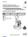 1
1
-
 2
2
-
 3
3
-
 4
4
-
 5
5
-
 6
6
-
 7
7
-
 8
8
-
 9
9
-
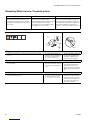 10
10
-
 11
11
-
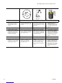 12
12
-
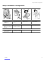 13
13
-
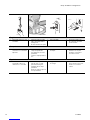 14
14
-
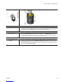 15
15
-
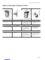 16
16
-
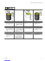 17
17
-
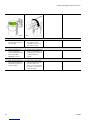 18
18
-
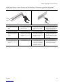 19
19
-
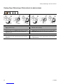 20
20
-
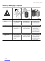 21
21
-
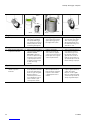 22
22
-
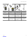 23
23
-
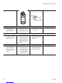 24
24
-
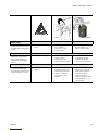 25
25
-
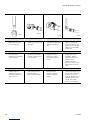 26
26
-
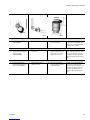 27
27
-
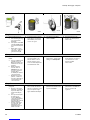 28
28
-
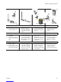 29
29
-
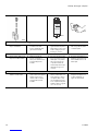 30
30
-
 31
31
-
 32
32
-
 33
33
-
 34
34
-
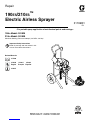 35
35
-
 36
36
-
 37
37
-
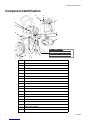 38
38
-
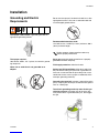 39
39
-
 40
40
-
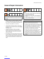 41
41
-
 42
42
-
 43
43
-
 44
44
-
 45
45
-
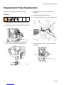 46
46
-
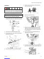 47
47
-
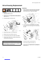 48
48
-
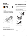 49
49
-
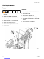 50
50
-
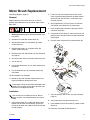 51
51
-
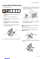 52
52
-
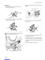 53
53
-
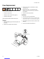 54
54
-
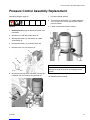 55
55
-
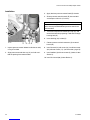 56
56
-
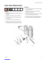 57
57
-
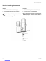 58
58
-
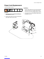 59
59
-
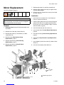 60
60
-
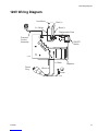 61
61
-
 62
62
-
 63
63
-
 64
64
-
 65
65
-
 66
66


CJ Spray 966 Instrucciones de operación
- Categoría
- Rociador de pintura
- Tipo
- Instrucciones de operación
- Este manual también es adecuado para
En otros idiomas
- français: CJ Spray 966 Mode d'emploi
- English: CJ Spray 966 Operating instructions
Otros documentos
-
Graco Inc. 309365E Manual de usuario
-
Graco 311732C, 390 Electric Airless Sprayer Manual de usuario
-
Graco Inc. 826098 Manual de usuario
-
Graco 248661 Manual de usuario
-
-
-
-
O'Brien PRO 301 El manual del propietario
-