

COMPLIANCE INFORMATION STATEMENT
(DECLARATION OF CONFORMITY PROCEDURE)
Responsible Party: YAMAHA CORPORATION OF AMERICA
Address: 6600 Orangethorpe Avenue, Buena Park, Calif. 90620 U.S.A.
Telephone: 1-714-522-9011
FAX: 1-714-739-2680
Type of Equipment: AUDIO EXPANSION UNIT
Model Name: AX44
This device complies with Part 15 of the FCC Rules.
Operation is subject to the following conditions:
1) this device may not cause harmful interference, and
2) this device must accept any interference received including interference that may cause undesired operation.
Contents
Introduction - - - - - - - - - - - - - - - - - - - - - - - - - - - - - - - - - - - 1
Packing List - - - - - - - - - - - - - - - - - - - - - - - - - - - - - - - - - 1
System Requirements - - - - - - - - - - - - - - - - - - - - - - - - - - - 1
Controls & Connections - - - - - - - - - - - - - - - - - - - - - - - - - - 2
Front Panel - - - - - - - - - - - - - - - - - - - - - - - - - - - - - - - - - - 2
Rear Panel - - - - - - - - - - - - - - - - - - - - - - - - - - - - - - - - - - 3
Installing the AX44 - - - - - - - - - - - - - - - - - - - - - - - - - - - - - - 4
Installing a Second AX44 - - - - - - - - - - - - - - - - - - - - - - - - - 4
Troubleshooting - - - - - - - - - - - - - - - - - - - - - - - - - - - - - - - - 5
Specifications - - - - - - - - - - - - - - - - - - - - - - - - - - - - - - - - - - 6
General - - - - - - - - - - - - - - - - - - - - - - - - - - - - - - - - - - - - 6
Analog Inputs - - - - - - - - - - - - - - - - - - - - - - - - - - - - - 7
Analog Outputs - - - - - - - - - - - - - - - - - - - - - - - - - - - - - - - 7
DC IN Connector - - - - - - - - - - - - - - - - - - - - - - - - - - - - - 7
Dimensions - - - - - - - - - - - - - - - - - - - - - - - - - - - - - - - - - 8
FCC INFORMATION (U.S.A.)
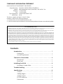
1. IMPORTANT NOTICE: DO NOT MODIFY THIS UNIT! This product, when installed as indicated in the instructions contained in this manual, meets FCC
requirements. Modifications not expressly approved by Yamaha may void your authority, granted by the FCC, to use the product.
2. IMPORTANT: When connecting this product to accessories and/or another product use only high quality shielded cables. Cable/s supplied with this product MUST
be used. Follow all installation instructions. Failure to follow instructions could void your FCC authorization to use this product in the USA.
3. NOTE: This product has been tested and found to comply with the requirements listed in FCC Regulations, Part 15 for Class “B” digital devices. Compliance with
these requirements provides a reasonable level of assurance that your use of this product in a residential environment will not result in harmful interference with
other electronic devices. This equipment generates/uses radio frequencies and, if not installed and used according to the instructions found in the users manual, may
cause interference harmful to the operation of other electronic devices. Compliance with FCC regulations does not guarantee that interference will not occur in all
installations. If this product is found to be the source of interference, which can be determined by turning the unit “OFF” and “ON”, please try to eliminate the
problem by using one of the following measures: Relocate either this product or the device that is being affected by the interference. Utilize power outlets that are on
different branch (circuit breaker or fuse) circuits or install AC line filter/s. In the case of radio or TV interference, relocate/reorient the antenna. If the antenna lead-in
is 300 ohm ribbon lead, change the lead-in to coaxial type cable. If these corrective measures do not produce satisfactory results, please contact the local retailer
authorized to distribute this type of product. If you can not locate the appropriate retailer, please contact Yamaha Corporation of America, Electronic Service
Division, 6600 Orangethorpe Ave, Buena Park, CA 90620
The above statements apply ONLY to those products distributed by Yamaha Corporation of America or its subsidiaries.

Introduction
1
AX44—Owner’s Manual
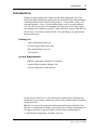
Introduction
Thank you for purchasing the Yamaha AX44 Audio Expansion Unit. The
AX44 is an input and output expander for the Yamaha DS2416 Digital Mixing
Card and provides four 1/4-inch analog inputs—two of which can be used
with microphones—four 1/4-inch analog outputs and a stereo headphone
jack. The 20-bit 128-times oversampling A/D converters and 18-bit 8-times
oversampling D/A converters provide a typical dynamic range of 100 dB. Two
AX44s can be used with a single DS2416 card, providing up to eight analog
inputs and outputs.
Packing List
• AX44 Audio Expansion Unit
• DS2416 20-pin connection cable
• M3 x 6 mm fixing screws x4
• This manual
System Requirements
• IBM PC compatible Windows 95 computer
• Yamaha DS2416 Digital Mixing Card
• DS2416 compatible audio software
No part of the AX44
Owner’s Manual
may be reproduced or distributed in
any form or by any means without the prior written authorization of Yamaha
Corporation, Inc.
IBM PC is a registered trademarks of International Business Machines, Inc.
Yamaha is a trademark of Yamaha Corporation, Inc. All other trademarks are
the property of their respective holders and are hereby acknowledged.
© 1998 Yamaha Corporation. All rights reserved.

2
Controls & Connections
AX44—Owner’s Manual
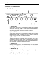
Controls & Connections
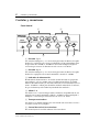
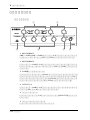
Front Panel
A
Inputs 1 & 2
Analog inputs 1 and 2 feature 1/4-inch unbalanced phone jacks with individ-
ual Line/Mic switches for –10 dBV or –50 dBV operation. Analog to digital
conversion features 20-bit 128-times oversampling techniques.
B
Inputs 3 & 4
Analog inputs 3 and 4 feature 1/4-inch unbalanced phone jacks with a nomi-
nal input level of –10 dBV. Use with line-level sources. Analog to digital con-
version uses 20-bit 128-times oversampling techniques.
C
Power Indicator
The Power indicator lights up when the AX44 is ready for use, that is, when
the computer is turned on and the AX44 is receiving power, and the connec-
tion to the DS2416 is functioning correctly. (It’s also used to identify AX44s
from the software, useful when two units are installed.)
D
Outputs 1–4
Outputs 1 through 4 feature 1/4-inch unbalanced phone jacks with a nominal
output level of –10 dBV. Digital to analog conversion features 18-bit 8-times
oversampling.
E
Headphone Jack
Outputs 3 and 4 can be monitored by connecting a pair of stereo headphones
to this 1/4-inch stereo jack.
F
Headphone Level Control
This control adjusts the volume level of the headphones.
INPUT 1 2 3 4
1234
OUTPUT
POWER
LINE MIC
–10dBV –50dBV –10dBV –50dBV
LINE MIC
AX44
4
21
3 5 6

Rear Panel
3
AX44—Owner’s Manual
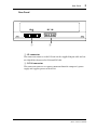
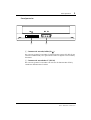
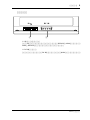
Rear Panel
A
IO connector
This connector connects to the DS2416 via the supplied 20-pin cable and car-
ries digital data between the AX44 and DS2416.
B
DC IN connector
This connector connects to a power connector from the computer’s power
supply and supplies power to the AX44.
IO DC IN
1 2

4
Installing the AX44
AX44—Owner’s Manual
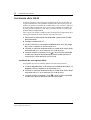
Installing the AX44
The AX44 installs into a single 5.25-inch drive bay, and is secured using the
four screws supplied. There are three sets of fixing holes in the AX44: two on
the sides and one underneath. Use the set that matches your computer’s drive
bay. If you need to replace a screw, look for M3 x 6 mm machine screws. Do
not use screws longer than 6 mm as they may damage the AX44.
See your computer’s manual for full details on installing drive bay devices.
1
Turn off the computer and disconnect the power cord.
2
Remove the computer’s cover.
3
Install the AX44 into a 5.25-inch drive bay, as explained in your
computer’s manual.
4
Connect an unused power connector from the computer’s power
supply to the AX44 DC IN connector.
5
Connect the AX44 to DS2416 connector “IO-A ( )” using the
supplied 20-pin cable (connect the end with the ferrite core to the
DS2416).
Installing a Second AX44
Two AX44 units can be connected to a single DS2416 card.
1
Install the second AX44 into a 5.25-inch drive bay, as explained in
your computer’s manual.
2
Connect an unused power connector from the computer’s power
supply to the AX44 DC IN connector.
3
Connect the second AX44 to DS2416 connector “IO-B ( )” using
the supplied 20-pin cable.
A
AB

Troubleshooting
5
AX44—Owner’s Manual
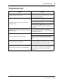
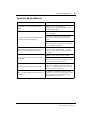
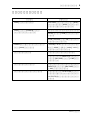
Troubleshooting
Trouble Advice
Lost the AX44 fixing screws?
Replace with M3 x 6 mm machine screws.
Do not use screws longer than 6 mm as they
may damage the AX44.
The AX44 does not work and the Power
indicator is off?
Make sure that the computer is turned on.
Make sure the power connector is properly
connected to the AX44.
Make sure the supplied 20-pin cable is con-
nected properly between the AX44 and
DS2416.
The Power indicator is on but the AX44 still
doesn’t work?
A single AX44 should be connected to
DS2416 connector “IO-A”; the second AX44
to connector “IO-B”.
The input signal sounds distorted?
Reduce the level of the input signal.
When connecting line-level equipment to
inputs 1 and 2, set the Mic/Line switches to
Line.
The input signal is too quiet?
Low-level signal sources such as micro-
phones should be connected to inputs 1 and
2 and the Mic/Line switch set to Mic.
Cannot hear anything in the headphones?
The headphone signal is derived from out-
puts 3 and 4, so you must assign signals to
these outputs in order to use the head-
phones.

6
Specifications
AX44—Owner’s Manual
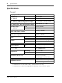
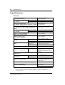
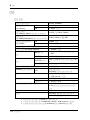
Specifications
General
1. Syncs to external wordclock. AX44 has no internal clock.
2. Bandwidth filter
±
0.1 dB (20 Hz–20 kHz), –60 dB (more than 24.1 kHz)
3. Bandwidth filter as above plus Weighting Filter (IEC60651 A curve, Tolerance: Type 0)
Sampling rate
1
30.08 to 50.88 kHz
Signal delay
(fs = 48 kHz)
A/D
610
µ
s typical
D/A
1,330
µ
s typical
Total harmonic distortion
2
(fs = 48 kHz, +6 dBV, analog input to output)
Less than 0.01% (20 Hz–20 kHz)
Frequency response
(fs = 48 kHz, Line, Mic, analog input to output)
20 Hz–20 kHz, –3, +1 dB
Dynamic range
3
(fs = 48 kHz)
D/A
Typically 106 dB
A/D + D/A
Typically 100 dB
Equivalent input noise
3
(Gain = Mic, input + output)
Typically –120 dBV
Residual output noise
3
(D/A input = digital 0)
Typically –100 dBV
Input
INPUT 1–4 20-bit 128-times oversampling A/D
INPUT 1, 2 MIC/LINE switch
Output
OUTPUT 1–4 18-bit 8-times oversampling D/A
Phones Source: outputs 3 and 4
Phones level control
Rotary pot
Power indicator
LED
Power on/off
Identity flag from DS2416
Power supply
+5 V (180 mA max)
+12 V (200 mA max)
Temperature
Operating
+10˚C to +40˚C
Storage
–20˚C to +55˚C
Dimensions (W x D x H)
148 x 183 x 42.6 mm
(5.8 x 7.2 x 1.7 inch)
For half-height 5.25" drive bay
Weight
1 kg (2.2 lbs)
Supplied accessories
20-pin DS2416 connecting cable x1
M3 x 6 mm fixing screws x4

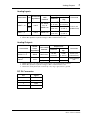
Analog Outputs
7
AX44—Owner’s Manual
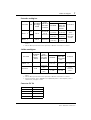
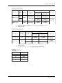
Analog Inputs
Analog Outputs
DC IN Connector
1. Input channels 1–4 feature linear 20-bit 128-times oversampling A/D converters.
2. Where dBV represents a specific voltage, 0 dBV is referenced to 1 V rms.
1. Output channels 1–4 feature linear 18-bit 8-times oversampling D/A converters.
2. Where dBV represents a specific voltage, 0 dBV is referenced to 1 V rms.
3. The Phones stereo phone jack is wired: tip = left, ring = right, sleeve = ground.
Connection Pad
Actual load
impedance
For use
with
nominal
Input level
Connector
Nominal
Max. before
clip
INPUT 1, 2
1
MIC
10k
Ω
50–600
Ω
mics &
600
Ω
lines
–50 dBV
2
(3.16 mV)
–34 dBV
(19.95 mV)
Phone jack
(unbalanced)
LINE
–10 dBV
(316 mV)
+6 dBV
(1.995 V)
INPUT 3, 4
10k Ω 600 Ω lines
–10 dBV
(316 mV)
+6 dBV
(1.995 V)
Connection
Actual
source
impedance
For use with
nominal
Output level
Connector
Nominal
Max. before
clip
OUTPUT 1–4
1
600 Ω 10k Ω lines
–10 dBV
2
(316 mV)
+6 dBV
(1.995 V)
Phone jack
(unbalanced)
Phones
3
22 Ω
8 Ω phones 1 mW 14 mW
Stereo phone
jack
40 Ω phones 1 mW 23 mW
Pin Signal
1 +12 V
2 GND
3 GND
4 +5 V

8 Specifications
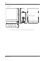
AX44—Owner’s Manual
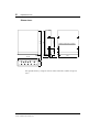
Dimensions
Specifications subject to change without notice.
M3 fixing holes (12 off)
139.711.8 10.65
D: 183
79.252.2
H: 42.6
W:148
5
188

AX44
BOÎTIER D’EXTENSION
Mode d’emploi
Français

Sommaire
Introduction - - - - - - - - - - - - - - - - - - - - - - - - - - - - - - - - - - - 1
Contenu de l’emballage - - - - - - - - - - - - - - - - - - - - - - - - - - 1
Configuration requise - - - - - - - - - - - - - - - - - - - - - - - - - - - 1
Commandes & connexions - - - - - - - - - - - - - - - - - - - - - - - - 2
Face avant - - - - - - - - - - - - - - - - - - - - - - - - - - - - - - - - - - 2
Face arrière - - - - - - - - - - - - - - - - - - - - - - - - - - - - - - - - - - 3
Installation de l’AX44 - - - - - - - - - - - - - - - - - - - - - - - - - - - - 4
Installation d’un deuxième AX44 - - - - - - - - - - - - - - - - - - - 4
Dépannage - - - - - - - - - - - - - - - - - - - - - - - - - - - - - - - - - - - - 5
Fiche technique - - - - - - - - - - - - - - - - - - - - - - - - - - - - - - - - - 6
Caractéristiques générales - - - - - - - - - - - - - - - - - - - - - - - - 6
Entrées analogiques - - - - - - - - - - - - - - - - - - - - - - - - - 7
Sorties analogiques - - - - - - - - - - - - - - - - - - - - - - - - - - - - - 7
Connecteur DC IN - - - - - - - - - - - - - - - - - - - - - - - - - - - - - 7
Dimensions - - - - - - - - - - - - - - - - - - - - - - - - - - - - - - - - - 8

Introduction
1
AX44—Mode d’emploi
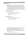
Introduction
Nous vous remercions d’avoir opté pour le boîtier d’extension Yamaha AX44.
L’AX44 est un boîtier d’extension entrées/sorties pour la Yamaha DS2416
Digital Mixing Card qui propose quatre sorties analogiques 1/4 de pouce
(dont deux peuvent servir pour des microphones), quatre sorties analogiques
1/4 de pouce et une borne pour casque stéréo. Les convertisseurs A/N 20 bits
avec suréchantillonnage à 128 fois et les convertisseurs N/A 18 bits avec suré-
chantillonnage à 8 fois offrent une plage dynamique typique de 100 dB. Il est
possible d’utiliser deux AX44 avec une seule carte DS2416 afin de disposer de
huit entrées et sorties analogiques.
Contenu de l’emballage
• Boîtier d’extension AX44 (Audio Expansion Unit)
• Câble de connexion à 20 broches du DS2416
• Vis de fixation M3 x 6 mm x4
•Ce manuel
Configuration requise
• Ordinateur compatible IBM PC avec Windows 95
• Yamaha DS2416 Digital Mixing Card
• Logiciel audio compatible DS2416
Il est interdit de reproduire ou de distribuer le
Mode d’emploi
de l’AX44 en
tout ou en partie, sous quelque forme ou par quelque moyen que ce soit sans
autorisation préalable et écrite de Yamaha Corporation, Inc.
IBM PC est une marque déposée de International Business Machines, Inc.
Yamaha est une marque commerciale de Yamaha Corporation, Inc. Toutes les
autres marques sont la propriété de leurs détenteurs respectifs et sont recon-
nues par la présente.
© 1998 Yamaha Corporation. Tous droits réservés.

2
Commandes & connexions
AX44—Mode d’emploi
Commandes & connexions
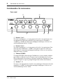
Face avant
A
Entrées 1 & 2
Les entrées analogiques 1 et 2 sont pourvues de jacks 1/4 asymétriques avec
un commutateur Line/Mic individuel leur permettant de sélectionner
–10 dBV ou –50 dBV. La conversion analogique/numérique se fait avec un
suréchantillonnage 20 bits à 128 fois.
B
Entrées 3 & 4
Les entrées analogiques 3 et 4 sont pourvues de jacks 1/4 asymétriques d’un
niveau d’entrée nominal de –10 dBV et sont prévues pour des sources de
niveau ligne. La conversion analogique/numérique se fait avec un suréchan-
tillonnage 20 bits à 128 fois.
C
Témoin POWER
Le témoin POWER s’allume lorsque l’ordinateur est sous tension et indique
que l’AX44 est alimenté et prêt à l’usage et que la connexion avec la carte
DS2416 fonctionne correctement. (Il permet également d’identifier les AX44
à partir du logiciel, ce qui est pratique lorsque vous utilisez deux boîtiers).
D
Sorties 1~4
Les sorties 1 à 4 sont pourvues de jacks 1/4 asymétriques d’un niveau de sortie
nominal de –10 dBV. La conversion numérique/analogique se fait avec un
suréchantillonnage 18 bits à 8 fois.
INPUT 1 2 3 4
1234
OUTPUT
POWER
LINE MIC
–10dBV –50dBV –10dBV –50dBV
LINE MIC
AX44
4
21
3 5 6

Face arrière
3
AX44—Mode d’emploi
E
Prise pour casque
Vous pouvez écouter les sorties 3 et 4 en branchant un casque à cette prise sté-
réo.
F
Commande de volume du casque
Cette commande permet de régler le volume du casque.
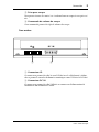
Face arrière
A
Connecteur IO
Ce connecteur permet de relier la carte DS2416 avec le câble fourni à 20 bro-
ches et permet le transfert de données numériques entre l’AX44 et le DS2416.
B
Connecteur DC IN
Ce connecteur permet de relier l’AX44 à un connecteur d’alimentation de
l’ordinateur afin d’alimenter l’AX44.
IO DC IN
1 2

4
Installation de l’AX44
AX44—Mode d’emploi
Installation de l’AX44
L’AX44 s’insère dans une baie simple de 5,25 pouces. Fixez-la avec les quatre
vis fournies. Il y a trois séries d’orifices de fixation dans l’AX44: deux sur les
côtés et un en-dessous. Servez-vous des orifices qui correspondent à ceux de
la baie de votre ordinateur. Si vous devez remplacer une vis, demandez une vis
pour machine M3 x 6 mm. N’utilisez pas de vis plus longues que 6 mm car
elles risqueraient d’endommager l’AX44.
Veuillez consulter le manuel de votre ordinateur pour en savoir davantage sur
l’installation d’appareils dans les baies.
1
Coupez l’ordinateur et débranchez le cordon d’alimentation.
2
Enlevez le cache de l’ordinateur.
3
Installez l’AX44 dans une baie de 5,25 pouces en suivant les expli-
cations données dans le manuel de votre ordinateur.
4
Branchez un connecteur d’alimentation inutilisé de l’ordinateur au
connecteur DC IN de l’AX44.
5
Branchez l’AX44 au connecteur “IO-A ( )” du DS2416 avec le
câble à 20 broches fourni (Connectez le côté en ferrite à la
DS2416).
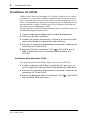
Installation d’un deuxième AX44
Vous pouvez brancher deux boîtiers AX44 à une seule carte DS2416.
1
Installez le deuxième AX44 dans une baie de 5,25 pouces en sui-
vant les explications données dans le manuel de votre ordinateur.
2
Branchez un connecteur d’alimentation inutilisé de l’ordinateur au
connecteur DC IN de l’AX44.
3
Branchez le deuxième AX44 au connecteur “IO-B ( )” du DS2416
avec le câble à 20 broches fourni.
A
AB

Dépannage
5
AX44—Mode d’emploi
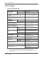
Dépannage
Problème Conseil
Les vis de fixations de l’AX44 sont égarées.
Remplacez-les par des vis machine M3 x
6 mm. N’utilisez pas de vis plus longues que
6 mm car elles pourraient endommager
l’AX44.
L’AX44 ne fonctionne pas et l’indicateur
POWER est éteint.
Assurez-vous que l’ordinateur est sous ten-
sion.
Assurez-vous que le connecteur d’alimenta-
tion est correctement raccordé à l’AX44.
Assurez-vous que le câble à 20 broches est
correctement relié à l’AX44 et à la carte
DS2416.
L’indicateur POWER est allumé mais l’AX44
ne fonctionne toujours pas.
Un boîtier AX44 unique doit être branché au
connecteur “IO-A” de la carte DS2416; bran-
chez le second au connecteur “IO-B”.
Le signal d’entrée est saturé?
Réduisez le niveau du signal d’entrée.
Lorsque vous branchez du matériel de niveau
ligne aux entrées 1 et 2, réglez les commuta-
teurs Mic/Line sur Line.
Le signal d’entrée est-il trop faible?
Les sources de signaux de faible niveau tels
que des microphones doivent être branchées
aux entrées 1 et 2 et le commutateur
Mic/Line doit être réglé sur Mic.
Vous n’entendez rien via le casque?
Le signal du casque est dérivé des sorties 3 et
4; il faut donc assigner les signaux à ces sor-
ties pour pouvoir utiliser le casque.

6
Fiche technique
AX44—Mode d’emploi
Fiche technique
Caractéristiques générales
1. Synchronisation sur horloge externe. L’AX44 n’a pas d’horloge interne.
2. Largeur de bande du filtre
±
0,1 dB (20 Hz–20 kHz), –60 dB (plus de 24,1 kHz)
3. Largeur de bande du filtre comme ci-dessus plus Filtre de pondération (IEC60651 courbe A,
Tolérance: Type 0)
Fréquence d’échantillonnage
1
30,08 à 50,88 kHz
Retard de signal
(fs = 48 kHz)
A/N
610
µ
s typique
N/A
1,330
µ
s typique
Distorsion harmonique totale
2
(fs = 48 kHz, +6 dBV, entrée vers sortie
analogique)
Moins de 0,01% (20 Hz–20 kHz)
Réponse en fréquence
(fs = 48 kHz, Ligne, Mic, entrée vers sortie
analogique)
20 Hz–20 kHz, –3, +1 dB
Plage dynamique
3
(fs = 48 kHz)
D/A
Typiquement 106 dB
A/D + D/A
Typiquement 100 dB
Bruit d’entrée équivalent
3
(Gain = Mic, entrée + sortie)
Typiquement –120 dBV
Bruit de sortie résiduel
3
(entrée N/A = numérique 0)
Typiquement –100 dBV
Entrée
INPUT 1~4
A/N 20 bits suréchantillonnage à 128
fois
INPUT 1, 2 Commutateur MIC/LINE
Sortie
OUTPUT 1~4
N/A 18 bits suréchantillonnage à 8
fois
Casque Source: sorties 3 et 4
Commande de volume du casque
Potentiomètre rotatif
Témoin POWER
Diode
Sous/hors tension
Flag d’identité du DS2416
Alimentation
+5 V (180 mA max)
+12 V (200 mA max)
Température
Fonctionnement
+10˚C à +40˚C
Stockage
–20˚C à +55˚C
Dimensions (L x P x H)
148 x 183 x 42,6 mm
(5,8 x 7,2 x 1,7 inch)
Pour baie mi-hauteur de 5,25 pouces
Poids
1 kg (2,2 lbs)
Accessoires fournis
Câble de connexion à 20 broches
pour DS2416 x1
Vis de fixation M3 x 6 mm x4

Sorties analogiques
7
AX44—Mode d’emploi
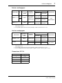
Entrées analogiques
Sorties analogiques
Connecteur DC IN
1. Les canaux d’entrée 1~4 disposent de convertisseurs A/N linéaires 20 bits avec suréchan-
tillonnage à 128 fois.
2. Lorsque dBV représente une tension spécifique, 0 dBV est référencé à 1 V rms.
1. Les canaux de sortie 1~4 disposent de convertisseurs N/A linéaires 18 bits avec suréchan-
tillonnage à 8 fois.
2. Lorsque dBV représente une tension spécifique, 0 dBV est référencé à 1 V rms.
3. Voici le câblage du jack du casque: pointe = gauche, anneau = droite, gaine = masse.
Connexion Att.
Impédance
de charge
réelle
Niveau
nominal
Niveau d’entrée
Connecteur
Nominal
Max. avant
saturation
INPUT 1, 2
1
MIC
10k
Ω
50–600
Ω
micro &
600
Ω
ligne
–50 dBV
2
(3,16 mV)
–34 dBV
(19,95 mV)
Jack
(asymétrique)
LINE
–10 dBV
(316 mV)
+6 dBV
(1,995 V)
INPUT 3, 4
10k
Ω
600
Ω
ligne
–10 dBV
(316 mV)
+6 dBV
(1,995 V)
Connexion
Impédance
de source
réelle
Niveau
nominal
Niveau de sortie
Connecteur
Nominal
Max. avant
saturation
OUTPUT 1~4
1
600 Ω 10k Ω ligne
–10 dBV
2
(316 mV)
+6 dBV
(1,995 V)
Jack
(asymétrique)
Casque
3
22 Ω
8 Ω casque 1 mW 14 mW
Prise pour cas-
que stéréo
40 Ω casque 1 mW 23 mW
Broche Signal
1 +12 V
2 Masse
3 Masse
4 +5 V

8 Fiche technique
AX44—Mode d’emploi
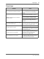
Dimensions
Caractéristiques susceptibles d’être modifiées sans préavis.
Orifices M3 (renfoncés 12)
139.711.8 10.65
P: 183
79.252.2
H: 42.6
L: 148
5
188

AX44
AUDIO EXPANSION UNIT
Bedienungsanleitung
Deutsch

Inhalt
Vorweg - - - - - - - - - - - - - - - - - - - - - - - - - - - - - - - - - - - - - - - 1
Lieferumfang - - - - - - - - - - - - - - - - - - - - - - - - - - - - - - - - 1
Systemanforderungen - - - - - - - - - - - - - - - - - - - - - - - - - - - 1
Bedienelemente & Anschlüsse - - - - - - - - - - - - - - - - - - - - - - 2
Frontplatte - - - - - - - - - - - - - - - - - - - - - - - - - - - - - - - - - - 2
Rückseite - - - - - - - - - - - - - - - - - - - - - - - - - - - - - - - - - - - 3
Einbau der AX44 - - - - - - - - - - - - - - - - - - - - - - - - - - - - - - - - 4
Einbau einer weiteren AX44 - - - - - - - - - - - - - - - - - - - - - - - 4
Problembehebung - - - - - - - - - - - - - - - - - - - - - - - - - - - - - - 5
Spezifikationen - - - - - - - - - - - - - - - - - - - - - - - - - - - - - - - - - 6
Allgemein - - - - - - - - - - - - - - - - - - - - - - - - - - - - - - - - - - - 6
Analog-Eingänge - - - - - - - - - - - - - - - - - - - - - - - - - - - 7
Analog-Ausgänge - - - - - - - - - - - - - - - - - - - - - - - - - - - - - - 7
DC IN-Anschluß - - - - - - - - - - - - - - - - - - - - - - - - - - - - - - 7
Abmessungen - - - - - - - - - - - - - - - - - - - - - - - - - - - - - - - - 8

Vorweg
1
AX44—Bedienungsanleitung
Vorweg
Vielen Dank, daß Sie sich für die Audio-Erweiterung AX44 von Yamaha ent-
schieden haben. Hierbei handelt es sich um eine Ein- und Ausgangserweite-
rung für die Digital-Mischpultkarte DS2416 mit vier 1/4-Zoll-Analog-
Eingängen –darunter zwei für Mikrofonsignale–, vier Analog-Ausgängen und
einem Stereo-Kopfhöreranschluß. Dank der 20-Bit A/D-Wandler mit
128fachem Oversampling und der 18-Bit D/A-Wandler mit 8fachem Over-
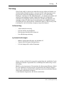
sampling verfügen Sie über einen Dynamikumfang von 100dB. Es können
zwei AX44 mit einer DS2416-Karte verbunden werden, so daß Sie insgesamt
8 Analog-Ein- und acht Analog-Ausgänge ansprechen können.
Lieferumfang
• AX44 Audio-Erweiterung
• DS2416 20-Pin-Anschlußkabel
• Befestigungsschrauben M3 x 6mm x4
• Diese Bedienungsanleitung
Systemanforderungen
• IBM PC-kompatibler Rechner mit Windows 95
• Yamaha DS2416 Digital-Mischpultkarte
• DS2416-kompatibles Audio-Programm
Nichts aus dieser AX44
Bedienungsanleitung
darf ohne die schriftliche Geneh-
migung der Yamaha Corporation, Inc vervielfältigt oder anderweitig verwen-
det werden.
IBM PC ist ein eingetragenes Warenzeichen der International Business Mach-
ines, Inc. Yamaha ist ein eingetragenes Warenzeichen der Yamaha Corpora-
tion, Inc. Alle anderen Warenzeichen sind Eigentum der betreffenden Firmen
und werden ausdrücklich anerkannt.
© 1998 Yamaha Corporation. Alle Rechte vorbehalten.

2
Bedienelemente & Anschlüsse
AX44—Bedienungsanleitung
Bedienelemente & Anschlüsse
Frontplatte
A
Eingang (Input) 1 & 2
Die Analog-Eingänge 1 und 2 sind als asymmetrische 1/4"-Klinkenbuchsen
mit LINE/MIC-Schaltern ausgeführt und erlauben einen Eingangspegel von
–10dBV oder –50dBV. Die dahintergeschalteten A/D-Wandler sind vom Typ
20 Bit mit 128fachem Oversampling.
B
Eingang (Input) 3 & 4
Die Analog-Eingänge 3 und 4 sind als asymmetrische 1/4"-Klinkenbuchsen
mit einem Nenneingangspegel von –10dBV ausgeführt. Schließen Sie hier
Signale mit Line-Pegel an. Die dahintergeschalteten A/D-Wandler sind vom
Typ 20 Bit mit 128fachem Oversampling.
C
POWER-Diode
Diese Diode leuchtet, sobald Sie den Rechner einschalten und zeigt an, daß
die AX44 mit Strom versorgt wird und ordnungsgemäß mit der DS2416 ver-
bunden ist. (Außerdem können Sie sie verwenden, um vom Audio-Pro-
gramm aus zu kontrollieren, ob die Karte angesprochen wird, was vor allem
bei Verwendung zweier AX44 hilfreich sein kann.)
D
Ausgänge (Output) 1~4
Die Ausgänge 1~4 sind als asymmetrische 1/4"-Klinkenbuchsen mit einem
Nennausgangspegel von –10dBV ausgeführt. Die davor geschalteten D/A-
Wandler sind vom Typ 18 Bit mit 8fachem Oversampling.
INPUT 1 2 3 4
1234
OUTPUT
POWER
LINE MIC
–10dBV –50dBV –10dBV –50dBV
LINE MIC
AX44
4
21
3 5 6

Rückseite
3
AX44—Bedienungsanleitung
E
Kopfhöreranschluß
Das Signal von Ausgang 3 und 4 kann auch über einen an diese 1/4"-Stereo-
Klinkenbuchse angeschlossenen Kopfhörer überwacht werden.
F
Lautstärkeregler für den Kopfhöreranschluß
Hiermit können Sie die Lautstärke im Kopfhörer einstellen.
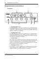
Rückseite
A
E/A-Anschluß (IO )
Verbinden Sie diesen Anschluß über das beiliegende 20-Pin-Kabel mit der
DS2416 Karte. Über dieses Kabel werden die Daten von und zur Karte über-
tragen.
B
DC IN-Anschluß
Verbinden Sie diesen Anschluß mit der Stromversorgung des Rechners, um
die AX44 mit Strom zu versorgen.
IO DC IN
1 2

4
Einbau der AX44
AX44—Bedienungsanleitung
Einbau der AX44
Die AX44 kann in einen einfachen 5,25"-Schacht des Rechners geschoben
und mit den vier beiliegenden Schrauben befestigt werden. Die AX44 ist mit
drei Bohrungssätzen versehen: zwei an den Seiten und einer an der Unterseite.
Falls Sie eine Schraube verlieren, können Sie eine beliebige andere M3 x
6mm-Schraube verwenden. Gebrauchen Sie niemals längere Schrauben, weil
die AX44 sonst beschädigt werden könnte.
Wie man ein Gerät in einen Schacht einbaut, entnehmen Sie bitte der Bedie-
nungsanleitung Ihres Rechners.
1
Schalten Sie den Rechner aus und lösen Sie den Netzanschluß.
2
Öffnen Sie das Gehäuse des Rechners.
3
Schieben Sie die AX44 in einen 5,25”-Schacht. Beachten Sie dabei
die Hinweise in der Bedienungsanleitung des Rechners.
4
Verbinden Sie ein noch freies Stromkabel des Rechners mit dem
DC IN-Anschluß der AX44.
5
Verbinden Sie den 20-Pin-Anschluß der AX44 mit der “IO-A ( )”-
Buchse der DS2416 (Schließen Sie das Ende mit der Ferritleitung
an die DS2416 an).
Einbau einer weiteren AX44
Es können jeweils zwei AX44 mit einer DS2416-Karte verbunden werden.
1
Schieben Sie die zweite AX44 in einen noch freien 5,25”-Schacht.
Beachten Sie dabei die Hinweise in der Bedienungsanleitung des
Rechners.
2
Verbinden Sie ein noch freies Stromkabel des Rechners mit dem
DC IN-Anschluß der AX44.
3
Verbinden Sie den 20-Pin-Anschluß der Zweiten AX44 mit der “IO-
B ( )”-Buchse der DS2416.
A
B

Problembehebung
5
AX44—Bedienungsanleitung
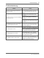
Problembehebung
Problem Lösung
Finden Sie die Befestigungsschrauben der
AX44 nicht mehr?
Kein Problem, nehmen Sie einfach andere
M3 x 6mm-Metallschrauben. Verwenden
aber niemals Schrauben, die länger sind als
6mm.
Die AX44 funktioniert nicht und die POWER-
Diode leuchtet nicht.
Schauen Sie nach, ob der Rechner einge-
schaltet ist.
Schauen Sie nach, ob das Stromkabel des
Rechners ordnungsgemäß mit der AX44 ver-
bunden ist.
Schauen Sie nach, ob das 20-Pin-Kabel ord-
nungsgemäß mit der AX44 und der DS2416
verbunden ist.
Die POWER-Diode leuchtet, aber die AX44
kann nicht angesprochen werden.
Wenn Sie nur eine AX44 verwenden, müssen
Sie die mit der “IO/A”-Buchse der DS2416
verbinden. Schließen Sie eine weitere AX44
an die “IO/B”-Buchse an.
Das Eingangssignal verzerrt.
Verringern Sie den Pegel des Eingangssignals.
Wenn Sie Signalquellen mit Line-Pegel an Ein-
gang 1 oder 2 anschließen, müssen Sie sei-
nen LINE/MIC-Schalter auf LINE stellen.
Das Eingangssignal ist zu schwach.
Niederpegelige Signale, wie z.B. Mikrofone
müssen mit Eingang 1 oder 2 verbunden
werden. Stellen Sie den betreffenden LINE/
MIC-Schalter dann auf MIC.
Der Kopfhörer gibt kein Signal wieder.
Der Kopfhörer führt nur das Signal von Aus-
gang 3 und 4. Legen Sie die betreffenden
Signale also an diese Buchsen an, um sie über
Kopfhörer überwachen zu können.

6
Spezifikationen
AX44—Bedienungsanleitung
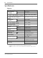
Spezifikationen
Allgemein
1. Synchronisation mit externem Wordclock-Takt. Die AX44 enthält keinen Taktgeber.
2. Bandbreite des Filters
±
0,1 dB (20 Hz~20 kHz), –60 dB (mehr als 24,1 kHz)
3. Bandbreite des Filters wie oben, dazu ein gewichtetes Filter (IEC60651 A-Kurve, Toleranz:
Typ 0)
Sampling-Frequenz
1
30,08~50,88 kHz
Signalverzögerung
(fs = 48 kHz)
A/D
610
µ
s typisch
D/A
1,330
µ
s typisch
Klirrfaktor
2
(fs = 48 kHz, +6 dBV, Analog-Ein- zu -Ausgang)
Weniger als 0,01% (20 Hz–20 kHz)
Frequenzgang
(fs = 48 kHz, LINE, MIC, Analog-Ein- zu -
Ausgang)
20 Hz~20 kHz, –3, +1 dB
Dynamikumfang
3
(fs = 48 kHz)
D/A
Typisch 106 dB
A/D + D/A
Typisch 100 dB
Äquivalentes Eingangsrauschen
3
(Gain = MIC, Eingang + Ausgang)
Typisch –120 dBV
Restausgangsrauschen
3
(D/A-Eingang = Digital-Ausgang)
Typisch –100 dBV
Eingänge
INPUT 1~4 A/D 20 Bit, 128faches Oversampling
INPUT 1, 2 LINE/MIC-Schalter
Ausgänge
OUTPUT 1~4 D/A 18 Bit, 8faches Oversampling
Phones Quelle: Eingang 3 und 4
Kopfhörerlautstärke
Drehpotentiometer
Stromanzeige
LED
Ein-/ausgeschaltet
Identitäts-Flag der DS2416
Stromversorgung
+5 V (180 mA max.)
+12 V (200 mA max.)
Empfohlene Temperatur
Bei Verwendung
+10˚C ~+40˚C
Lagerung
–20˚C~+55˚C
Abmessungen (B x T x H)
148 x 183 x 42,6 mm
Für halbhohen 5,25"-Schacht
Gewicht
1kg
Lieferumfang
20-Pin DS2416-Anschlußkabel x1
M3 x 6mm Schrauben x4

Analog-Ausgänge
7
AX44—Bedienungsanleitung
Analog-Eingänge
Analog-Ausgänge
DC IN-Anschluß
1. Die Eingangskanäle 1~4 sind mit 20-Bit D/A-Wandlern mit 128fachem Oversampling aus-
gestattet.
2. Wenn dBV einen Spannungswert vertritt, entspricht 0dBV dem Wert 1V rms.
1. Die Ausgangskanäle 1~4 sind mit 18-Bit D/A-Wandlern mit 8fachem Oversampling ausge-
stattet.
2. Wenn dBV einen Spannungswert vertritt, entspricht 0dBV dem Wert 1V rms.
3. Bedrahtung der Stereo-Klinkenbuchse: Spitze= links, Ring= rechts, Mantel= Masse.
Anschluß Pad
Tats. Last-
impedanz
Bei Verw.
mit Nenn-
pegel
Eingangspegel
Anschlußtyp
Nennwert
Max. vor
Verzerrung
INPUT 1, 2
1
MIC
10k
Ω
50–600
Ω
Mikrofon &
600
Ω
Line
–50 dBV
2
(3,16 mV)
–34 dBV
(19,95 mV)
Klinkenbuchse
(asymmetrisch)
LINE
–10 dBV
(316 mV)
+6 dBV
(1,995 V)
INPUT 3, 4
10k
Ω
600
Ω
Line
–10 dBV
(316 mV)
+6 dBV
(1,995 V)
Anschluß
Tats. Quel-
lenimpe-
danz
Bei Verw.
mit Nenn-
wert
Ausgangspegel
Anschlußtyp
Nennwert
Max. vor
Verzerrung
OUTPUT 1~4
1
600 Ω 10k Ω Line
–10 dBV
2
(316 mV)
+6 dBV
(1,995 V)
Klinkenbuchse
(asymmetrisch)
Phones
3
22 Ω
8 Ω Kopfh. 1 mW 14 mW
Stereo-Klinken-
buchse
40 Ω Kopfh. 1 mW 23 mW
Stift Signal
1 +12 V
2 GND (Masse)
3 GND (Masse)
4 +5 V

8 Spezifikationen
AX44—Bedienungsanleitung
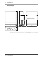
Abmessungen
Änderungen der technischen Daten ohne Vorankündigung jederzeit vorbehalten.
M3-Bohrungen (12 versetzt)
139.711.8 10.65
T: 183
79.252.2
H: 42.6
B:148
5
188

AX44
AUDIO EXPANSION UNIT
Manual de instrucciones
Español

Indice
Introducción - - - - - - - - - - - - - - - - - - - - - - - - - - - - - - - - - - - 1
Lista de envío - - - - - - - - - - - - - - - - - - - - - - - - - - - - - - - - 1
Requisitos del sistema - - - - - - - - - - - - - - - - - - - - - - - - - - - 1
Contoles y conexiones - - - - - - - - - - - - - - - - - - - - - - - - - - - - 2
Panel frontal - - - - - - - - - - - - - - - - - - - - - - - - - - - - - - - - - 2
Panel posterior - - - - - - - - - - - - - - - - - - - - - - - - - - - - - - - 3
Instalación de la AX44 - - - - - - - - - - - - - - - - - - - - - - - - - - - - 4
Instalación de una segunda AX44 - - - - - - - - - - - - - - - - - - - 4
Solución de problemas - - - - - - - - - - - - - - - - - - - - - - - - - - - 5
Especificaciones - - - - - - - - - - - - - - - - - - - - - - - - - - - - - - - - 6
Generales - - - - - - - - - - - - - - - - - - - - - - - - - - - - - - - - - - - 6
Entradas analógicas - - - - - - - - - - - - - - - - - - - - - - - - - 7
Salidas analógicas - - - - - - - - - - - - - - - - - - - - - - - - - - - - - - 7
Conector DC IN - - - - - - - - - - - - - - - - - - - - - - - - - - - - - - 7
Dimensiones - - - - - - - - - - - - - - - - - - - - - - - - - - - - - - - - - 8

Introducción
1
AX44—Manual de instrucciones
Introducción
Muchas gracias por la adquisición de la unidad de expansión de audio AX44
Yamaha. La AX44 es un expansor de entrada y salida para la tarjeta de mezcla
digital DS2416 Yamaha que proporciona cuatro entradas analógicas de 1/4
pulgadas – dos de las cuales podrán utilizarse con micrófonos – cuatro salidas
analógicas de 2/4 pulgadas, y una toma para auriculares estéreo. Los converti-
dores A/D con sobremuestreo de 128 veces de 20 bits y los convertidores A/D
con sobremuestreo de 8 veces de 18 bits proporcionan una gama dinámica
típica de 100 dB. Usted podrá utilizar dos AX44 con una sola tarjeta DS2416
para obtener hasta ocho entradas y salidas analógicas.
Lista de envío
• Unidad de expansión de audio AX44
• Cable conector DS2416 de 20 contactos
• 4 tornillos de fijación M3 x 6 mm
• Este manual
Requisitos del sistema
• PC con Windows 95 compatible con IBM PC
• Tarjeta de mezcla digital DS2416 Yamaha
• Software de audio compatible con DS2416
Ninguna parte de este Manual de instrucciones de la unidad AX44 deberá
reproducir ni distribuirse en ninguna forma o mediante ningún medio sin la
autorización por escrito de Yamaha Corporation, Inc.
IBM PC es marca registrada de International Business Machines, Inc.
Yamaha es marca comercial de Yamaha Corporation, Inc. Todas las demás
marcas son propiedad de sus respectivos propietarios y aquí están reconoci-
das como tal.
© 1998 Yamaha Corporation. Reservados todos los derechos.

2
Contoles y conexiones
AX44—Manual de instrucciones
Contoles y conexiones
Panel frontal
A
Entradas 1 y 2
Las entradas analógicas 1 y 2 se caracterizan por tomas telefónicas desequili-
bradas de 1/4 pulgadas con selectores individuales de línea/micrófono apara
la operación con –10 dBV o –50 dBV. La conversión analógica a digital se
caracteriza por técnicas de sobremuestreo de 128 veces de 20 bits.
B
Entradas 3 y 4
Las entradas analógicas 3 y 4 se caracterizan por tomas telefónicas desequili-
bradas de 1/4 pulgadas con un nivel nominal de entrada de –10 dBV.
C
Indicador de alimentación
El indicador de alimentación se encenderá cuando la AX44 esté preparada
para utilizarse, es decir, cuando conecte la alimentación del PC, la unidad
AX44 reciba alimentación y la conexión a DS2416 esté funcionando correcta-
mente. (También se utiliza para identificar unidades AX44 desde el software,
lo que resultará muy útil cuando haya instalado dos unidades.)
D
Salidas 1-4
Las salidas 1 a 4 se caracterizan por tomas telefónicas desequilibradas de 1/4
pulgadas con un nivel nominal de salida de –10 dBV. la conversión digital a
analógica se caracteriza por sobremuestreo de 8 veces de 18 bits.
E
Toma para auriculares
Las salidas 3 y 4 podrán monitorearse conectando unos auriculares estéreo a
esta toma estéreo de 1/4 pulgadas.
F
Control de nivel de los auriculares
Este control ajusta el nivel del volumen de los auriculares.
INPUT 1 2 3 4
1234
OUTPUT
POWER
LINE MIC
–10dBV –50dBV –10dBV –50dBV
LINE MIC
AX44
4
21
3 5 6

Panel posterior
3
AX44—Manual de instrucciones
Panel posterior
A
Conector de entrada/salida (IO )
Este conector permite la conexión a la tarjeta DS2416 a través del cable de 20
contactos suministrado y sirve para trnsferir datos de digitales entre la AX44 y
la DS2416.
B
Conector de entrada de CC (DC IN)
Este conector permite la conexión a un conector de alimentación del PC y
suministra alimentación a la AX44.
IO DC IN
1 2

4
Instalación de la AX44
AX44—Manual de instrucciones
Instalación de la AX44
La AX44 se instala en una ranura para unidad de disco de 5,25 pulgadas, y se
asegura utilizando los cuatro tornillos suministrados. Existen tres juegos de
orificios de fijación en la AX44, dos a ambos lados y otro en la base. Utilice el
juego adecuado a la ranura de su PC. Si necesita reemplazar un tornillo, uti-
lice uno para metal de M3 x 6 mm. No use tornillos de más de 6 mm ya que
podrían dañar la unidad AX44.
Con respecto a los detalles completos sobre la instalación de dispositivos en la
ranura para unidades de disco, consulte el manual de su PC.
1
Desconecte la alimentación del ordenador y desenchufe el cable
de alimentación.
2
Extraiga la cubierta del PC.
3
Instale la AX44 en la ranura para unidad de disco de 5,325 pulga-
das, como se explica en el manual de su PC.
4
Conecte un conector de alimentación no usado de la fuente de ali-
mentación de su PC en el conector DC IN de la AX44.
5
Conecte la AX44 al conector “IO-A ( )” de la DS2416 utilizando
el cable con conector de 20 contactos suministrado (Conecte el
extremo con núcleo de ferrita a la DS2416).
Instalación de una segunda AX44
Usted podrá conectar dos unidades AX44 a una sola tarjeta DS2416.
1
Instale la segunda AX44 en la ranura para unidad de disco de 5,25
pulgadas, como se explica en el manual de su PC.
2
Conecte un conector de alimentación no usado de la fuente de ali-
mentación de su PC en el conector DC IN de la AX44.
3
Conecte la AX44 al conector “IO-B ( )” de la DS2416 utilizando
el cable con conector de 20 contactos suministrado.
A
AB

Solución de problemas
5
AX44—Manual de instrucciones
Solución de problemas
Problema
Sugerencia
¿Ha perdido los tornillos de fijación de la
AX44?
Utilice otros tornillos M3 x 6 mm.
No use tornillos de más de 6 mm, ya que
podría dañar la AX44.
¿La AX44 no funciona y el indicador de ali-
mentación permanece apagado?
Cerciórese de que la alimentación de su PC
esté conectada.
Cerciórese de que el conector de aliment-
ación esté correctamente conectado a la
AX44.
Cerciórese de que el cable con conector de
20 contactos esté correctamente conectado
entre la AX44 y la DS2416.
¿El indicador de alimentación está encen-
dido pero la AX44 sigue sin funcionar?
Si utiliza una sola AX44, deberá conectarla al
conector “IO-A” de la DS2416, y si utiliza
dos, la segunda deberá conectarla al conec-
tor “IO-B”.
¿Se oyen distorsionado el sonido de la señal
de entrada?
Reduzca el nivel de la señal de entrada.
Cuando haya conectado un equipo de nivel
de línea a las entradas 1 y 2, ponga los selec-
tores de micrófono/línea en línea.
¿Es demasiado débil la señal de entrada?
Las fuentes de señal de bajo nivel, como
micrófonos, deberán conectarse a las entra-
das 1 y 2, y tendrá que poner el selector de
micrófono/línea en micrófono.
¿No es posible escuchar nada a través de los
auriculares?
La señal de los auriculares se deriva de las
salidas 3 y 4, motivo por el que usted tendrá
que asignar señales a estas salida a fin de
poder utilizar los auriculares.

6
Especificaciones
AX44—Manual de instrucciones
Especificaciones
Generales
1. El sincronismo con el reloj de palabra AX44 no tiene reloj interno
2. Filtro de anchura de banda
±
0,1 dB (20 Hz–20 kHz), –60 dB (más de 24,1 kHz)
3. Filtro de anchura de banda como arriba más filtro de ponderación (IEC60651 curva A,
Tolerancia: tipo 0)
Frecuencia de muestreo
1
30,08 a 50,88 kHz
Retardo de la señal
(fs = 48 kHz)
A/D
610
µ
s típica
D/A
1.330
µ
s típica
Distorsión armónica total
2
(fs = 48 kHz, +6 dBV, Entradas analógicas a salidas)
Menos de 0,01%
(20 Hz–20 kHz)
Respuesta en frecuencia
(fs = 48 kHz, Línea, Mic, Entradas analógicas a
salidas)
20 Hz–20 kHz, –3, +1 dB
Gama dinámica
3
(fs = 48 kHz)
D/A
Típica 106 dB
A/D + D/A
Típica 100 dB
Ruido de entrada equivalente
3
(Gain = Mic, entrada + salida)
Típica –120 dBV
Ruido de salida residual
3
(D/A entrada = digital 0)
Típica –100 dBV
Entrada
INPUT 1–4
Lineal de 20 bitios, A/D con
sobremuestreo de 128 veces
INPUT 1, 2 Interruptor MIC/LINE
Salida
OUTPUT 1–4
Lineal de 18 bitios, A/D con
sobremuestreo de 8 veces
Auriculares Fuente: Salidas 3 y 4
Control de nivel de los auriculares
Potenciómetro giratorio
Indicador de alimentación
LED
Conexión/desconexión de la
alimentación
Bandera de identificación desde
DS2416
Alimentación
+5 V (180 mA máx)
+12 V (200 mA máx)
Temperatura
Funcionamiento
+10˚C a +40˚C
Almacenamiento
–20˚C a +55˚C
Dimensiones (An x Al x Prf)
148 x 183 x 42,6 mm
Ranura para unidad de 5,25" de
media altura
Peso
1 kg (2,2 librs)
Accesorios suministrados
1 cable conector de DS2416 de
20 contactos
4 tornillos de fijación M3 x 6 mm

Salidas analógicas
7
AX44—Manual de instrucciones
Entradas analógicas
Salidas analógicas
Conector DC IN
1. Los canales de entrada 1–4 utilizan convertidores A/D con sobremuestreo de 128 veces de
20 bitos.
2. Cuando dBV representa una tensión específica, 0 dBV hace referencia a 1 V eficaces.
1. Los canales de entrada 1–4 utilizan convertidores A/D con sobremuestreo de 18 veces de
8 bitos.
2. Cuando dBV representa una tensión específica, 0 dBV hace referencia a 1 V eficaces.
3. La toma telefónica estéreo PHONES está equilibrada: punta = canal izquierdo, anillo =
canal derecho, manguito = masa.
Conexión Pad
Impedancia
de carga
actual
Para
utilización
con valor
nominal
Nival de entrada
Conector
Nominal
Máxima
antes del
descresta
miento
INPUT 1, 2
1
Mic
10k
Ω
50–600
Ω
mic &
600
Ω
línea
–50 dBV
2
(3,16 mV)
–34 dBV
(19,95 mV)
Toma
telefónica
(desequili-
brada)
Línea
–10 dBV
(316 mV)
+6 dBV
(1,995 V)
INPUT 3, 4
10k
Ω
600
Ω
línea
–10 dBV
(316 mV)
+6 dBV
(1,995 V)
Conexión
Impedancia
de la
fuente
actual
Para
utilización
con valor
nominal
Nival de salida
Conector
Nominal
Máxima
antes del
descrestami
ento
OUTPUT 1–4
1
600
Ω
10k
Ω
línea
–10 dBV
2
(316 mV)
+6 dBV
(1,995 V)
Toma telefónica
(desequilibrada)
Auriculares
3
22
Ω
8
Ω
auricu-
lares
1 mW 14 mW
Toma
telefónica
estéreo
40
Ω
auricu-
lares
1 mW 23 mW
Contacto Señal
1 +12 V
2 GND
3 GND
4 +5 V

8
Especificaciones
AX44—Manual de instrucciones
Dimensiones
Las especificaciones y el aspecto externo están sometidos a cambio sin previo
aviso.
Tornillos de fijación M3 (12 fuera)
139.711.8 10.65
Al: 183
79.252.2
Prf: 42.6
An:148
5
188

AX44
M
☎


©

INPUT 1 2 3 4
1234
OUTPUT
POWER
LINE MIC
–10dBV –50dBV –10dBV –50dBV
LINE MIC
AX44
4
21
3 5 6

IO DC IN
1 2

A
B


µ
µ


139.711.8 10.65
79.252.2
5
188

-
 1
1
-
 2
2
-
 3
3
-
 4
4
-
 5
5
-
 6
6
-
 7
7
-
 8
8
-
 9
9
-
 10
10
-
 11
11
-
 12
12
-
 13
13
-
 14
14
-
 15
15
-
 16
16
-
 17
17
-
 18
18
-
 19
19
-
 20
20
-
 21
21
-
 22
22
-
 23
23
-
 24
24
-
 25
25
-
 26
26
-
 27
27
-
 28
28
-
 29
29
-
 30
30
-
 31
31
-
 32
32
-
 33
33
-
 34
34
-
 35
35
-
 36
36
-
 37
37
-
 38
38
-
 39
39
-
 40
40
-
 41
41
-
 42
42
-
 43
43
-
 44
44
-
 45
45
-
 46
46
-
 47
47
-
 48
48
-
 49
49
-
 50
50
-
 51
51


