Yamaha DSP-A2070 El manual del propietario
- Categoría
- Receptores AV
- Tipo
- El manual del propietario

DSP
-
A2070
DIGITAL SOUND FIELD
PROCESSING AMPLIFIER
OPERATION MANUAL
CONTENTS
SAFETY INSTRUCTIONS..................................................Inside Front cover
SETUP & ADJUSTMENT..............................................................................3
1-1.GETTING STARTED...............................................................................3
1-2.SETUP....................................................................................................10
1-3.CONTROLS & ADJUSTMENTS...........................................................19
1-4.ADJUSTMENT.......................................................................................23
GENERAL OPERATION .............................................................................29
2-1.PLAYING A SOURCE ...........................................................................29
2-2.RECORDING A SOURCE TO AUDIO/VIDEO TAPE..........................30
(OR DUBBING FROM A TAPE TO ANOTHER)
2-3.DIGITAL SOUND FIELD PROGRAMS.................................................31
2-4.SELECTING SOUND FIELD PROGRAMS..........................................31
2-5.MUTING THE EFFECT SOUND...........................................................32
2-6.SUPERIMPOSED VIDEO PROGRAM/PARAMETER
DISPLAY................................................................................................32
2-7.DESCRIPTIONS OF THE SOUND FIELD PROGRAMS.....................33
2-8.REMOTE CONTROL “LEARNING” FUNCTION..................................39
CREATING YOUR OWN SOUND FIELDS.................................................41
3-1.SELECTING AND EDITING PROGRAM PARAMETERS...................41
3-2.DESCRIPTIONS OF THE DIGITAL SOUND FIELD
PARAMETERS......................................................................................43
TABLES & SPECIFICATIONS....................................................................48
4-1.PROGRAM PARAMETER TABLE........................................................48
4-2.TROUBLESHOOTING ..........................................................................51
4-3.SPECIFICATIONS.................................................................................52

1 Read Instructions – All the safety
and operating instructions should be
read before the unit is operated.
2 Retain Instructions – The safety and
operating instructions should be retained
for future reference.
3 Heed Warnings – All warnings on the
unit and in the operating instructions
should be adhered to.
4 Follow Instructions – All operating
and other instructions should be
followed.
5 Water and Moisture – The unit
should not be used near water – for
example, near a bathtub, washbowl,
kitchen sink, laundry tub, in a wet
basement, or near a swimming pool, etc.
6 Carts and Stands – The unit should
be used only with a cart or stand that is
recommended by the manufacturer.
6A A unit and cart
combination should be
moved with care. Quick
stops, excessive force,
and uneven surfaces may
cause the unit and cart
combination to overturn.
7 Wall or Ceiling Mounting – The unit
should be mounted to a wall or ceiling
only as recommended by the
manufacturer.
8 Ventilation – The unit should be
situated so that its location or position
does not interfere with its proper
ventilation. For example, the unit should
not be situated on a bed, sofa, rug, or
similar surface, that may block the
ventilation openings; or placed in a built-
in installation, such as a bookcase or
cabinet that may impede the flow of air
through the ventilation openings.
9 Heat – The unit should be situated
away from heat sources such as
radiators, stoves, or other appliances
that produce heat.
10 Power Sources – The unit should be
connected to a power supply only of the
type described in the operating
instructions or as marked on the unit.
11 Power-Cord Protection – Power-
supply cords should be routed so that
they are not likely to be walked on or
pinched by items placed upon or against
them, paying particular attention to cords
at plugs, convenience receptacles, and
the point where they exit from the unit.
12 Cleaning – The unit should be
cleaned only as recommended by the
manufacturer.
13 Nonuse Periods – The power cord of
the unit should be unplugged from the
outlet when left unused for a long period
of time.
14 Object and Liquid Entry – Care
should be taken so that objects do not
fall into and liquids are not spilled into
the inside of the unit.
15 Damage Requiring Service – The
unit should be serviced by qualified
service personnel when:
A. The power-supply cord or the plug
has been damaged;
or
B. Objects have fallen, or liquid has
been spilled into the unit; or
C. The unit has been exposed to rain;
or
D. The unit does not appear to operate
normally or exhibits a marked change in
performance;
or
E. The unit has been dropped, or the
cabinet damaged.
16 Servicing – The user should not
attempt to service the unit beyond those
means described in the operating
instructions. All other servicing should
be referred to qualified service
personnel.
17 Power Lines – An outdoor antenna
should be located away from power
lines.
18 Grounding or Polarization –
Precautions should be taken so that the
grounding or polarization is not defeated.
SAFETY INSTRUCTIONS
RISK OF ELECTRIC SHOCK
DO NOT OPEN
CAUTION: TO REDUCE THE RISK OF
ELECTRIC SHOCK, DO NOT REMOVE
COVER (OR BACK), NO USER-SERVICEABLE
PARTS INSIDE, REFER SERVICING TO
QUALIFIED SERVICE PERSONNEL.
The lightning flash with arrowhead
symbol, within an equilateral triangle,
is intended to alert you to the
presence of uninsulated “dangerous
voltage” within the product’s
enclosure that may be of sufficient
magnitude to constitute a risk of
electric shock to persons.
The exclamation point within an
equilateral triangle is intended to alert
you to the presence of important
operating and maintenance
(servicing) instructions in the
literature accompanying the
appliance.
•
Explanation of Graphical Symbols
CAUTION
IMPORTANT!
Please record the serial number of this
unit in the space below.
Model:
Serial No.:
The serial number is located on the rear
of the unit.
Retain this Owner’s Manual in a safe
place for future reference.
WARNING
TO REDUCE THE RISK OF FIRE OR
ELECTRIC SHOCK, DO NOT EXPOSE
THIS UNIT TO RAIN OR MOISTURE.
PRECAUTIONS & SAFETY INSTRUCTIONS

1 To ensure the finest performance,
please read this manual carefully. Keep it
in a safe place for future reference.
2 Install your unit in a cool, dry, clean
place – away from windows, heat sources,
and too much vibration, dust, moisture or
cold. Avoid sources of hum (transformers,
motors). To prevent fire or electrical shock,
do not expose to rain and water.
3 Do not operate the unit upside-down. It
may overheat, possibly causing damage.
4 Never open the cabinet. If a foreign
object drops into the set, contact your
dealer.
5 Do not use force on switches, knobs or
cords. When moving the set, first turn the
unit off. Then gently disconnect the power
plug and the cords connecting to other
equipment. Never pull the cord itself.
6 Do not attempt to clean the unit with
chemical solvents; this might damage the
finish. Use a clean, dry cloth.
7 Always set the volume control to “–
∞
”
while lowering the tonearm to play a
record; turn the volume up with the stylus in
the groove.
8 Be sure to read the “Troubleshooting”
section on common operating errors before
concluding that your unit is faulty.
9 Do not connect audio equipment to
the AC outlets on the rear panel if that
equipment requires more power than the
outlets are rated to provide.
We Want You Listening
For A Lifetime
YAMAHA and the Electronic Industries
Association’s Consumer Electronics
Group want you to get the most out of
your equipment by playing it at a safe
level. One that lets the sound come
through loud and clear without annoying
blaring or distortion – and, most
importantly, without affecting your
sensitive hearing. Since hearing
damage from loud sounds is often
undetectable until it is too late, YAMAHA
and the Electronic
Industries Association’s
Consumer Electronics
Group recommend you to
avoid prolonged exposure
from excessive volume
levels.
PRECAUTIONS
FCC INFORMATION
1. IMPORTANT NOTICE : DO NOT MODIFY THIS UNIT!
This product, when installed as indicated in the instructions contained in this
manual, meets FCC requirements. Modifications not expressly approved by
Yamaha may void your authority, granted by the FCC, to use the product.
2. IMPORTANT : When connecting this product to accessories and/or another
product use only high quality shielded cables. Cable/s supplied with this
product MUST be used. Follow all installation instructions. Failure to follow
instructions could void your FCC authorization to use this product in the USA.
3. NOTE : This product has been tested and found to comply with the
requirements listed in FCC Regulations, Part 15 for Class “B” digital devices.
Compliance with these requirements provides a reasonable level of assurance
that your use of this product in a residential environment will not result in
harmful interference with other electronic devices.
This equipment generates/uses radio frequencies and, if not installed and used
according to the instructions found in the users manual, may cause interference
harmful to the operation of other electronic devices.
Compliance with FCC regulations does not guarantee that interference will not
occur in all installations. If this product is found to be the source of
interference, which can be determined by turning the unit “OFF” and “ON”,
please try to eliminate the problem by using one of the following measures:
Relocate either this product or the device that is being affected by the
interference.
Utilize power outlets that are on different branch (circuit breaker or fuse)
circuits or install AC line filter/s.
In the case of radio or TV interference, relocate/reorient the antenna. If the
antenna lead-in is 300 ohm ribbon lead, change the lead-in to coaxial type
cable.
If these corrective measures do not produce satisfactory results, please contact
the local retailer authorized to distribute this type of product. If you can not
locate the appropriate retailer, please contact Yamaha Electronics Corp.,
U.S.A. 6660 Orangethorpe Ave, Buena Park, CA 90620.
The above statements apply ONLY to those products distributed by Yamaha
Corporation of America or its subsidiaries.
1

Congratulations!
You are the proud owner of a Yamaha Digital Sound Field Processing (DSP) System—an
extremely sophisticated audio component. The DSP system takes full advantage of Yamaha’s
undisputed leadership in the field of digital audio processing to bring you a whole new world
of listening experiences. Follow the instructions in this manual carefully when setting up your
system, and the DSP system will sonically transform your room into a wide range of listening
environments—anything from a famous concert hall to a cozy jazz club. In addition, you get
incredible realism from Dolby-encoded video tapes using the built-in Dolby Pro Logic
Surround Decoder.
Seven built-in channels of amplification on the DSP-A2070 mean that no additional
amplifiers are required to enjoy advanced digital sound field processing.
Rather than tell you about the wonders of digital sound field processing, however, let’s get
right down to the business of setting up the system and trying out its many capabilities.
Please read this operation manual carefully and store it in a safe place for later reference.
2

1-1. GETTING STARTED
Unpacking
If you haven’t already done so, carefully remove this unit and its
accessories from the box and wrapping material. You should find the
unit itself and the following accessories.
Installing the Remote Control Unit Batteries
Since the remote control unit will be used for many of this unit’s
control operations, you should begin by installing the supplied
batteries.
1. Turn the remote control unit over and slide the battery
compartment cover downward in the direction of the arrow.
2. Insert the batteries (LR6, AA, UM-3 type), being careful to align
them with the polarity markings on the inside of the battery
compartment.
3. Close the battery compartment cover.
3
SETUP & ADJUSTMENT
Remote control
Batteries User program sheets

●
When you notice that remote control operation has become
erratic, or the distance from which the remote control will function
has decreased, it’s time to replace the batteries. Always replace
all batteries at the same time.
●
Make sure that the YPC/USER/LEARN switch on the remote
control unit is set to the YPC or USER position for normal
operation.
●
This remote control uses an advanced, highly directional infrared
beam. Be sure to aim the remote control directly at the remote
control sensor on the main unit when operating.
Remote control transmitter operation range
Notes
●
There should be no large obstacles between the remote
control transmitter and the main unit.
●
If the remote control sensor is directly illuminated by strong
lighting (especially an inverter type of fluorescent lamp etc.),
it might cause the remote control transmitter to work
incorrectly. In this case, reposition the main unit to avoid
direct lighting.
Digital Sound Field Processing
What is it that makes live music so good? Today’s advanced
sound reproduction technology lets you get extremely close to the
sound of a live performance, but chances are you’ll still notice
something missing, the acoustic environment of the live concert hall.
Extensive research into the exact nature of the sonic reflections that
create the ambience of a large hall has made it possible for Yamaha
engineers to bring you this same sound in your own listening room,
so you’ll feel all the sound of a live concert. What’s more, our
technicians, armed with sophisticated measuring equipment, have
even made it possible to capture the acoustics of a variety of actual
concert halls, jazz clubs, theaters, etc. from around the world, to
allow you to accurately recreate any one of these live performance
environments, all in your own home.
4
30°
30°
Infrared receiver
Within approximately
7 m (23 feet)

Dolby Pro Logic Surround
The Dolby Pro Logic Surround Decoder program lets you
experience the dramatic realism and impact of Dolby Surround movie
theater sound in your own home. Dolby Pro Logic gets its name from
its professional-grade steering logic circuitry, which provides greater
effective channel separation for a much higher degree of realism than
the “passive” Dolby Surround circuits found in today’s typical home
audio/video equipment. Dolby Pro Logic Surround provides a true
center channel, so that there are four independent channels, unlike
passive Dolby Surround, which has in effect only three channels: left,
right, and rear. This center channel allows listeners seated in even
less-than-ideal positions to hear the dialog originating from the action
on the screen while experiencing good stereo imaging.
This Dolby Pro Logic Surround Decoder employs a digital signal
processing system. This system improves the stability of sound at
each channel and crosstalk between channels, so that positioning of
sounds around the room is more accurate compared with
conventional analog signal processing systems.
In addition, this unit features a built-in automatic input balance
control. This always assures you the best performance without
manual adjustment.
Manufactured under license from Dolby Laboratories Licensing
Corporation. Additionally licensed under one or more of the
following patents: U.S. number 3,950,590; Canadian numbers
1,004,603 and 1,037,877. “Dolby”, “Pro Logic”, and the double-D
symbol are trademarks of Dolby Laboratories Licensing
Corporation.
Dolby Pro Logic Surround + DSP
You can also enjoy Dolby Pro Logic with two modes of Digital
Sound field processing. These combinations expand the surround
effect. One is the “ENHANCED” Dolby Pro Logic Surround, which
recreates the surround effect of the 35 mm film movie theater. The
other is the sound field program “MOVIE THEATER”, which recreates
the listening experience of a 70 mm film theater.
Directional Enhancement Circuit + DSP
The YAMAHA directional enhancement (DIR. ENHANCEMENT)
circuit expands and focuses the digital sound field.
This effect puts you in the midst of the action, while centering and
focusing your attention to the screen. This circuit is available on
Sound Field programs “CONCERT VIDEO” and “TV THEATER”.
5

Setting Up Your Speaker System
This unit has been designed to provide the best sound field
quality with a full seven-speaker system setup, using two extra pairs
of effect speakers to generate the sound field plus one center
speaker for dialog, when using Dolby Pro Logic Surround decoding.
We therefore recommend that you use a seven-speaker setup. A
four-speaker system using only one pair of effect speakers for the
sound field will still provide impressive ambience and effects,
however, and may be a good way to begin with this unit. You can
always upgrade to the full seven speaker system later. In the 4 or 5
speaker system, the Digital Sound Field Processing is still
performed, but the main speakers are used for both the main
channels and the front effect channels.
Use of the Center Dialog Speaker Is Recommended
With digital sound field programs No. 7 through No. 12, by using
either the Directional Enhancement circuit or the Dolby Pro Logic
decoder, decoded signals will be output from the center channel.
Therefore, if you want to upgrade the Audio/Video home theater
system, it is recommended to use the center speaker unit.
If for some reason it is not practical to use a center speaker, it is
possible to enjoy movie viewing without it. Best results, however, are
obtained with the full system.
It is also possible to further expand your system with the addition
of a subwoofer and amplifier. You may wish to choose the
convenience of a Yamaha Active Servo Processing Sub Woofer
System, which has its own built-in power amp.
6

Four Possible Types of Speaker System Configurations Recommended
7
4 Speaker System
Simplest system.
You can enjoy widely diffused sound by
only adding two additional speaker units
at the rear.
FRONT MIX switch—Set to ON.
(See page 13.)
Center Mode—Set to PHNTM.
(See page 26.)
5 Speaker System
Good for Audio/Video sources and
Dolby Pro Logic Surround.
With sound field programs No. 7
through No. 12, which utilize the center
speaker effect, more precise center
localization can be obtained.
FRONT MIX switch—Set to ON.
(See page 13.)
Center Mode—Set to NRML or WD.
(See page 26.)
6 Speaker System
Good for sound fields from 2-channel
stereo sources.
With sound field programs No. 1
through No. 6, a sound effect matching
that of a 7-speaker system can be
obtained. The addition of front left and
right effect speakers produces a more
effective sound field.
FRONT MIX switch—Set to OFF.
(See page 13.)
Center Mode—Set to PHNTM.
(See page 26.)
7 Speaker System
This is the recommended speaker
system, providing the best sound
effects.
With sound field programs No. 1
through No. 6, using both sets of effect
speakers (front and rear), reproduces
the most effective sound field. With the
sound field programs No. 7 through No.
12, the center speaker provides precise
center localization.
FRONT MIX switch—Set to OFF.
(See page 13.)
Center Mode—Set to NRML or WD.
(See page 26.)

Speakers and Speaker Placement
Your full seven-speaker system will require three speaker pairs:
the MAIN SPEAKERS (your normal stereo speakers), the FRONT
EFFECT SPEAKERS, and the REAR EFFECT SPEAKERS, plus the
CENTER SPEAKER. You may also be using a subwoofer.
You will probably use your present stereo speakers as the MAIN
SPEAKER pair. The front effect, rear effect do not need to be equal
with the MAIN SPEAKERS, although the center speaker should be
as close as possible. They should have enough power handling
capacity to accept the maximum output of the DSP system or the
external amps that will drive them.
Place the MAIN SPEAKERS in the normal position.
Place the FRONT EFFECT SPEAKERS further apart than the
MAIN SPEAKERS, on either side of and a few feet behind and above
the MAIN SPEAKER pair.
Place the REAR EFFECT SPEAKERS behind your listening
position. They should be nearly six feet up from the floor.
Place the CENTER SPEAKER precisely between the two MAIN
SPEAKERS. (To avoid interference, keep the speaker above or
below the television monitor, or use a magnetically shielded speaker.)
If using a SUBWOOFER, such as a Yamaha Active Servo Sub-
woofer System, the position of the speaker is not so critical because
low bass tones are not highly directional.
NOTE: The Yamaha NS-C90 speaker, available in some countries, is
an ideal choice for the center speaker.
8
Main speaker Effect speaker Center speaker

VIDEO SUPERIMPOSE
If you connect your video cassette recorder, video disc player,
video monitor, etc. to this unit, you can take advantage of this unit’s
capability to display program titles, parameter data and information
about other various settings and adjustments on your video monitor’s
screen. This information will be superimposed over the video image.
If there is no video source connected or it is turned off, the
information will be displayed over a blue colored background (but no
video signal is input to this unit).
NOTE: The program titles, parameter data and other information are
also displayed on the display panel of this unit.
OPEN/CLOSE THE CONTROL DOOR
When it is not necessary to operate controls inside the control
door, close the door.
To close the door
To open the door
9
CONCERT HALL 1
Hall A in Europe

1-2. SETUP
Before you start making connections make sure all related electronic components are turned OFF.
REAR PANEL
CAUTION: TO PREVENT ELECTRIC SHOCK, DO NOT USE THIS
(POLARIZED) PLUG WITH AN EXTENSION CORD, RECEPTACLE OR
OTHER OUTLET UNLESS THE BLADES CAN BE FULLY INSERTED
TO PREVENT BLADE EXPOSURE.
10
240V
1
9 0 A B
2 3 4 5 6 7 8
C D E
F
G H I J LK
(General Model)

1 GND Terminal
Connects the ground wire of the turntable to produce minimum
hum. In some cases, however, better results may be obtained
with the ground wire disconnected.
2 Audio Signal Connection Jacks (for Audio Source Equipment)
Connect the inputs and/or outputs of your audio equipment.
3 Audio/Video Signal Connection Jacks (for Video Source
Equipment)
Connect the audio and video inputs and/or outputs of your video
equipment. In place of the VIDEO jacks, the S VIDEO jacks can
be used for higher resolution and improved picture quality if your
VCR, monitor, etc. are equipped with S-VIDEO connectors.
4 Main Speaker Terminals
When using this unit’s built-in main-channel amplifier, connect the
main speakers here. The jumper bars must be plugged in to
connect the MAIN IN jacks to the MAIN OUT jacks.
5 Front Effect Speaker Terminals
When using the built-in front-channel amplifier, connect the front
effect speakers here.
6 Center Speaker Terminals
When using the built-in center-channel amplifier, connect one or
two center speakers here.
7 Center Speaker Impedance Switch
Set to “A + B” when using two center speakers, or to “A or B”
when using only one center speaker.
8 Rear Effect Speaker Terminals
When using the built-in rear-channel amplifier, connect the rear
effect speakers here.
9 Video NTSC/PAL Switch (General Model only)
Set this switch to the position corresponding to the standard
that your video equipment employs.
0 Front Mix Switch
Set to “OFF” when setting up a full 7 or 6 speaker system, or to
“ON” when setting up a 5 or 4 speaker system.
A Main Level Control
Adjusts the main-channel line output level at the MAIN OUT
jacks. Used to achieve balance between the main and effect
speakers.
B Main Out Jacks
Main-channel line output. Connected with jumper bars to MAIN
IN jacks when the built-in amplifier is used. Connected to input
jacks of external stereo power amplifier (MAIN IN or TAPE PLAY
jacks of integrated amplifier or receiver) when using external
amplification.
C Main In Jacks
Line input to built-in main-channel amplifier. Connected with
jumper bars to MAIN OUT jacks when the built-in amplifier is
used. Not connected when using an external power amplifier.
D Center Out Jacks
Center-channel line outputs. Not connected when the built-in
amplifier is used. Can be connected to input jack(s) of one or two
external power amplifier(s) to drive the center speaker(s).
11

E Center In Jack
Line input to built-in center-channel amplifier. Connected with
jumper bars to CENTER OUT jack when the built-in amplifier is
used. Not connected when using an external power amplifier.
F Mono Low Pass Jack
When using a subwoofer, connect its amplifier input to this jack.
Frequencies below 200 Hz from the left main, right main and
center channels are output to this jack.
G Split Low Pass Jacks
When using two subwoofers, connect their amplifiers to these
jacks. Frequencies below 200 Hz from the left main and center
channels are output (in 10:7) to the SPLIT L jack, and also
frequencies below 200 Hz from the right main and center
channels are output (in 10:7) to the SPLIT R jack.
H Front Effect Out Jacks
Front-channel line output. Not connected when the built-in
amplifier is used. Can be connected to input jacks of an external
stereo power amplifier driving the front effect speakers.
I Rear Effect Out Jacks
Rear-channel line output. Not connected when the built-in
amplifier is used. Can be connected to input jacks of an external
stereo power amplifier driving the rear effect speakers.
J Voltage Selector (General Model only)
Be sure to set to the line voltage in your area before applying
power. Consult your dealer if unsure of the correct setting.
K Switched AC Outlets
You may plug other audio components into these sockets as long
as their combined power consumption does not exceed the
specified value shown. “Switched” means that these components
are turned on and off by this unit’s power switch.
L Unswitched AC Outlet (U.S.A., Canada, and General Model)
The total power consumption of audio components plugged into
this socket should not exceed the specified value shown.
“Unswitched” means that power is available even when this unit is
off.
NOTE: If an external power amplifier is connected to the front effect
or rear effect output jacks, the corresponding internal amplifier will be
turned off and no output will be available at the speaker terminals.
12

Rear Panel Switch and Control Settings
There are several switches and controls on the rear panel that
you’ll have to check before operating your system, and it’s a good
idea to do it before you connect cables. Locate the MAIN LEVEL
control (A) and FRONT MIX slide switch (:) at the bottom of the
MAIN terminal group. Make sure the MAIN LEVEL control is set to its
max (10) position and that the FRONT MIX switch is set to “OFF” for
7 or 6 speaker driving.
In a 5 or 4 speaker system, set the FRONT MIX switch to “ON”.
Next, set the NTSC/PAL switch (9) to the position corresponding
to the standard which your video equipments employ. (General
Model only)
General Instructions for Connections
Make sure that you have the left (L) and right (R) channels
correctly connected. That means that jacks marked “L” on this unit
must be connected to jacks marked “L” on other units. Likewise with
the “R” jacks. This is easy if you remember to always use the red
plug for the “R” jacks and the other plugs for the “L” jacks.
With speaker connections you must also be sure that the polarity
is correct. For each amplifier and each channel, connect the plus (+)
terminal of the amplifier to the plus terminal of the speaker, and
connect the minus (–) terminal of the amplifier to the minus terminal
of the speaker. To keep track of polarity, use a speaker cable that has
one of the two wires marked by a stripe or a different color.
13

CONNECTING AUDIO/VIDEO SOURCE EQUIPMENTS TO THIS UNIT
If you wish to connect a second monitor TV (or a projector) to this
unit, you can switch the VCR 3 VIDEO OUT jack (and S VIDEO jack
also) to a second monitor out jack. (See page 27.)
14
OUTPUT
OUTPUT
OUTPUT
LINE OUT
LINE IN
AUDIO OUT
VIDEO OUT
AUDIO OUT
VIDEO OUT
VIDEO IN
AUDIO IN
VIDEO IN
AUDIO IN
VIDEO OUT
AUDIO OUT
AUDIO OUT
VIDEO OUT
AUDIO OUT
VIDEO OUT
AUDIO OUT
VIDEO OUT
LINE OUT
LINE IN
GND
Turntable
CD player
Tuner
Tape deck 1
Tape deck 2
Monitor TV
Video disc player
TV/Satellite tuner
Video cassette recorder 1
Video cassette recorder 2
Video cassette recorder 3

CONNECTING TO S VIDEO JACKS
If your video cassette recorder, video disc player, etc. and your
monitor are equipped with “S” (high-resolution) video terminals,
connect them to this unit’s S VIDEO jacks, and connect this unit’s
S VIDEO MONITOR OUT jack to the “S” video input of your monitor.
Otherwise, connect the composite video jacks from your video
cassette recorder, video disc player, etc. to the VIDEO jacks of this
unit, and connect this unit’s VIDEO MONITOR OUT jack to the
composite video input of your monitor.
NOTE: If video signals are sent to both S VIDEO input and VIDEO
input jacks, the signals will be sent to their respective output jacks
independently.
NOTE: If your unit is the General Model, be sure the VIDEO
NTSC/PAL switch has been correctly set to the standard that your
video equipments employ. U.S. and Canadian models have no switch
and use the NTSC standard, while other models without a switch use
the PAL standard.
Notes about the Video superimpose
●
If you watch a video source that is connected to both S VIDEO and
VIDEO input jacks of this unit, signals of screen display information
are output from only the S VIDEO MONITOR OUT jack.
●
When no video signal is input to either S VIDEO or VIDEO input
jacks of this unit, signals of screen display information are output
from both S VIDEO MONITOR OUT and VIDEO MONITOR OUT
jacks with a color background.
* For the General Model, if the NTSC/PAL switch on the rear panel
is set to “PAL”, nothing will be output from either S VIDEO
MONITOR OUT or VIDEO MONITOR OUT jack in this case.
15
VIDEO
OUT
VIDEO OUT
S-VIDEO OUT
VIDEO IN
S-VIDEO IN
VIDEO IN
S-VIDEO
IN
S-VIDEO OUT
VIDEO OUT
VIDEO IN
VIDEO IN
S-VIDEO IN
S-VIDEO IN
S-VIDEO OUT
VIDEO OUT
S-VIDEO
OUT
VIDEO
OUT
S-VIDEO
OUT
Video disc player
Video cassette recorder 2
TV/Satellite tuner
Video cassette recorder 1
Video cassette recorder 3
Monitor TV

CONNECTING THE MAIN SPEAKERS TO THIS UNIT
Connect the MAIN speakers to the MAIN speaker output
terminals of this unit. Make sure that the jumper bars between the
MAIN OUT and MAIN IN jacks on the rear panel are in place. It is
also possible to use an external power amplifier if more power is
desired. In this case, remove the jumper bars and connect the MAIN
OUT jacks to the INPUT jacks of a stereo power amplifier with a
stereo pin cable—making sure to connect the left and right channels
correctly. Connect the MAIN speakers to the speaker output
terminals of the power amplifier.
NOTE: If an external amplifier is used for the main speakers, it is
recommended to use the MAIN speaker terminals of this unit for the
rear effect speakers.
Connect the REAR EFFECT OUT jacks to the MAIN IN jacks with
the pin cord. This combination is highly upgraded and ideal for the
division of sound quality, because the rear channel output of the
Audio/Video system is equally important as the center channel.
16
INPUT
MAIN UNIT
Main speaker
Power amplifier
This unit
Main speaker

CONNECTING THE EFFECT SPEAKERS TO THIS
UNIT
Connect the FRONT effect speakers to the FRONT effect
speaker output terminals of this unit.
If the FRONT effect speakers are not used, the FRONT MIX
switch should be set to “ON”.
Connect the REAR effect speakers to the REAR effect speaker
output terminals of this unit.
Connect the CENTER speaker to the CENTER speaker output
terminals. If you will be using one CENTER speaker, connect it to
either the A or B terminals and set the CENTER speaker impedance
switch to “A or B” (bottom position). If using two CENTER speakers,
connect them to the A and B terminals, and set the switch to “A + B”
(top position). If, however, you will not be using a CENTER speaker,
be sure to set the Center Mode to “PHNTM” (phantom). (See page
25.)
NOTE: The speaker connections above are fine for most
applications. If for some reason, however, you wish to use an
external power amp for any or all of the effect channels, connect the
line level output jack(s) for each channel to the INPUT jacks of the
external amp and connect the corresponding speaker pair to the
speaker terminals of the external amp.
NOTE: If the pin plug is inserted in the FRONT/REAR EFFECT out
jacks, the speaker output from the built-in amplifier will be cut off.
17
LR
LR
Front effect
speaker
Rear effect
speaker
Front effect
speaker
Rear effect
speaker
This unit
Center speaker Center speaker
Center speaker

ADDING A SUBWOOFER
You may wish to add a subwoofer to reinforce the bass
frequencies.
This unit provides line-level subwoofer outputs, which contain only
the frequencies under 200 Hz from the main and center channels. If
you use one subwoofer, connect the MONO LOW PASS jack to the
INPUT jack of the subwoofer amplifier, and connect the speaker
terminals of the subwoofer amplifier to the subwoofer.
If you wish to obtain more presence in your listening room, the
use of two subwoofers is recommended. To connect two subwoofers
to this unit, connect the “left” SPLIT LOW PASS jack to the INPUT
jack of the amplifier driving the left subwoofer, and the “right” SPLIT
LOW PASS jack to the INPUT jack of the amplifier driving the right
subwoofer, and then connect each subwoofer to the corresponding
amplifier.
With some subwoofers, including the Yamaha Active Servo
Processing Subwoofer System, the amplifier and subwoofer are in
the same unit.
CONNECTING SPEAKER SYSTEMS
Connect the SPEAKERS terminals to your speakers with wire of
the proper gauge, cut as short as possible. If the connections are
faulty, no sound will be heard from the speakers. Make sure that the
polarity of the speaker wires is correct, that is, + and – markings are
observed. If these wires are reversed, the sound will be unnatural
and will lack bass. Do not let the bare speaker wires touch each
other or any other metal part as this could damage this unit and/or
speakers.
Red: positive (+)
Black: negative (–)
1 Unscrew the knob.
2 Insert the bare wire.
3 Tighten the knob and
secure the wire.
NOTE: Use speakers with the specified impedance shown on the
rear of this unit.
NOTE: Banana Plug connections are also possible (except for
Scandinavian models). Simply insert the Banana Plug connector into
the corresponding terminal.
18
2
3
1

1-3. CONTROLS & ADJUSTMENTS
FRONT PANEL
19
1Power Switch
*STANDBY Mode (Europe model only)
While the power is on, pressing the POWER key on the remote
control unit switches the unit to the STANDBY mode. (In this
mode, the indicator is half illuminated.)
2Remote control sensor
Signals from the remote control unit are received here.
3 Pro Logic Decoder Indicator
Illuminates while the built-in Dolby Pro Logic Surround Decoder is
being activated.
4Sound Field Processor Indicator
Illuminates while the built-in Sound Field Processor is being
activated.
5Display Panel
Shows program names, parameters and information about other
various settings and adjustments.
6Tape 2 Monitor Switch
Used when you have connected a second tape deck to this unit’s
AUDIO SIGNAL TAPE 2 terminals to select that tape as the
source.
1
9 0 A DB E F HGC
34 5 6 7 82
I
(General Model)

7 Input Selector
Selects the input source that you want to listen to (and watch).
8 Master Volume Control
Simultaneously controls signal level at all outputs: front effect,
main, rear effect, center, and subwoofer. (This does not affect
TAPE REC OUT level.)
9 Phones Jack
Plug in headphones here for private listening. If the FRONT
MIX and EFFECT switches are on, the effect channels will
be heard along with the main channels. Otherwise the main
channels only will be heard.
: Input Level Over Indicator
Illuminates when the input level goes over the permissible
maximum level. If this occurs frequently, decrease the signal
level of the input source with the INPUT TRIM control,
otherwise the sound will be distorted.
A Bass Extension Switch
When on, boosts bass frequency response at the main left,
main right and center channels while maintaining overall
tonal balance. If you do not have a subwoofer, the use of
this switch will be effective to reinforce the bass frequencies.
B Input Trim Control
Adjusts the input level of each source respectively.
Moreover, performs setting or adjustment for items selected
by pressing the SET/MENU switch.
C Set Menu Switch
Whenever pressed, selects one of seven types of setting/adjust-
ment items. (They are CENTER MODE, CENTER GEQ, LOW
FREQ. TEST, PARAMETER INIT, MEMORY GUARD, VCR 3
VIDEO OUT and INPUT LVL TRIM.)
D Bass and Treble Controls
Adjust the sound to match your tastes. Can also be used to
compensate for room acoustics. Defeated in the center
position.
E Program Selector
Sequentially selects the digital sound field processing
programs in the + or – direction.
F Balance Control
Adjusts the left and right output volume to the Main
Speakers to compensate for sound imbalance caused by
speaker positions or listening room conditions.
G Effect Switch
Normally ON, this switch can be turned OFF to disable
output from the center and effect speakers.
H Rec Out Selector
Selects the source to be recorded to a tape deck 1 or
VCR 1 independently of the setting of the INPUT
SELECTOR. However, when set to the SOURCE position,
the setting of the INPUT SELECTOR decides the source to
be recorded to a tape deck or VCR.
I Auxiliary Input Jacks
Connect an auxiliary video or audio input source equipment
such as a camcorder to these jacks. If the connected video
equipment has a S video output terminal, connect it to the S
VIDEO jack to obtain a high resolution picture. The source
connected to these jacks can be selected by the INPUT
SELECTOR and REC OUT selector.
20

REMOTE CONTROL UNIT
1 Transmit/Learn Indicator
In Learn mode, lights to indicate that the key just pressed is ready
for learning input. In User mode, blinks when a learned key is
pressed to show that a control signal has been sent to your
equipment.
2 YPC/USER/LEARN Switch
Set to YPC for operating this unit and Yamaha equipments. Set to
USER for using learned key functions. Set to LEARN for learning
new control functions. (See page 39.)
(“YPC” is the abbreviation of YAMAHA Preset Code.)
3 Power Key
Turns this unit on and off.
* (Europe model only): Turns the POWER on mode to the
STANDBY mode and vice versa.
4 Source Select Keys
Select the input sources to this unit.
5 CD/LD Function Keys
Operate functions on your Yamaha CD player and LD player.
When the 1/2 Switch is set to 1, they operate the CD player, and
when set to 2, they operate the LD player.
6 Test Switch
When pressed, sends a signal to the main left, center, main
right, and rear effect speakers in turn, and when pressed once
again, sends a signal to the main and front effect speakers in
turn for easy comparison of level settings.
7 Front Level +/– Keys
Increase (+) or decrease (–) the volume level of the front effect
speakers.
21
M
L
K
J
I
G
H
DEBAC F
6
7
8
9
0
1
3
5
4
2

8 Center Level +/– Keys
Increase (+) or decrease (–) the volume level of the center
speaker(s).
9 Rear Level +/– Keys
Increase (+) or decrease (–) the volume level of the rear effect
speakers.
: Reset Button
Press this button to “reset” the internal microcomputer which
controls remote control operations. Microcomputer “reset” is
necessary when the remote control freezes.
* Pressing the RESET button will not erase learned functions.
A On Screen Display Key
Changes the type of display showing the program name and
parameters, or information about various settings/adjustments on
the connected monitor’s screen.
Whenever pressed, the screen changes to a full display,
simplified display and no display in turn.
B Clear Button
Used in USER or LEARN mode to erase a learned function. (See
page 40.)
C Effect On/Off Key
Cuts off the sound’s output from the front, rear effect and center
speakers. To restore the output from those speakers, press this
key again.
D Parameter Select Keys
Select program parameters or titles of settings/adjustments.
E Muting Key
Mutes the master volume level by 20 dB. While muting, the
indicator on the master VOLUME control flashes on and off
continuously.
F Parameter +/– Keys
Edit program parameters or used for seven types of
settings/adjustments.
G Master Volume +/– Keys
Increase (+) or decrease (–) the master volume level.
H Parameter/Set Menu Switch
When set to the PARAMETER position, the Parameter Select
Keys and Parameter +/– Keys will set and edit program
parameters. When set to the SET MENU position, the Parameter
Select Keys and Parameter +/– Keys are used to perform seven
types of settings/adjustments.
I Program Select Keys (1 through 12)
Select programs 1 through 12.
J Tuner Function Keys
Operate Yamaha tuner functions.
K Tape Deck Function Keys
Operate Yamaha tape deck functions.
L Blank Keys
Have no preset functions, so are used for learning other remote
controller’s functions only.
M 1/2 Switch
When the YPC/USER/LEARN Switch is set to YPC, this switches
the CD/LD Function Keys to keys for use with either the CD
player or LD player. (“1” for the CD player and “2” for the LD
player.) When the YPC/USER/LEARN Switch is set to USER or
LEARN, this switch selects page 1 or 2 for the learnable function
keys. (See page 39.)
22

1-4. ADJUSTMENT
MAIN/CENTER/EFFECT SPEAKER LEVEL BALANCE
ADJUSTMENT
This operation uses an internal test-tone generator for balancing
the levels of the main, center and effect speakers.
1. Depress the TEST switch on the remote control so that “TEST
DOLBY” appears in the display panel to enter test mode. A hiss-like
calibration signal should be heard from the left main speaker, center
speaker(s), right main speaker and rear effect speakers in turn (see
diagram). Adjust the MASTER VOLUME to a normal listening level.
2. Adjust the center and rear level by using the CENTER and REAR
LEVEL +/– keys on the remote control so that the sound coming from
the corresponding speakers seems to be at the same level as that
from the main speakers when you are at a normal listening position.
If there is insufficient volume from the effect speakers, you may
decrease the main speaker volume level by using the MAIN LEVEL
control on the rear panel and adjust the center and rear level again.
Volume controls on external power amplifiers may also be adjusted if
necessary to achieve proper balance.
3. For the front effect speaker level adjustment, depress the TEST
switch on the remote control again so that “TEST DSP” appears in
the display panel. A calibration signal should be heard from the main
speakers and the front effect speakers in turn (see diagram).
4. Adjust the front level by using the FRONT LEVEL +/– keys on the
remote control so that the speaker volume is the same as that of the
main speakers.
NOTE: If not using a center speaker, be sure to set the CENTER
MODE to the PHNTM (phantom) position. You will then hear the
center channel test tone from the left and right main speakers.
After completing this adjustment, press the TEST switch once
again.
NOTE: Once you have completed these adjustments, use only this
unit’s MASTER VOLUME control to adjust listening volume. Do not
change any other volume settings in the system.
23
Left main Center Right main
Rear
LEFT CENTER RIGHT
SURROUND
Main Front
MAIN FRONT

INPUT LEVEL ADJUSTMENT
This adjustment is important for obtaining the best performance
from the internal circuits of this unit. The optimum input level of this
unit is pre-adjusted on the basis of the CD source level. This
adjustment should be performed on all input sources in your system
respectively, so that their levels match the CD source level as closely
as possible.
1. Select the CD source.
2.
Play the source.
3. Increase the setting of the MASTER VOLUME control to a
convenient listening level (you will use this as your “reference” level).
4. Select any other source in your system (VCR, turntable, etc.) and
play that source.
5. Adjust the level of the source to be approximately equal to your
CD player’s “reference” level by using the INPUT TRIM control.
* This adjustment can also be done with the remote control unit.
For using the remote control unit, refer to “7. Input level
adjustment (INPUT LVL TRIM)” on page 28.
6. In the same way, adjust levels of other sources.
NOTE: The adjustments will be saved until it is readjusted.
NOTE: If the input level goes above the permissible maximum level,
the INPUT LEVEL OVER indicator on the front panel illuminates. If
this occurs frequently, decrease the signal level of the input source
with the INPUT TRIM control, otherwise the sound will be distorted.
24
VCR 1
VCR 3 PHONO
VCR 2 CD
TV/DBS
AUX
INPUT SELECTOR
TAPE 2
MONITOR
LD
TAPE 1
TUNER
AUX
PHONO
TAPE 1 TUNER CD
VCR 3
VCR 2
VCR 1 TV
/
DBS LD
Front panel Remote control
or
MASTER
VOLUME
Front panel Remote control
or
VCR 1
VCR 3 PHONO
VCR 2 CD
TV/DBS
AUX
INPUT SELECTOR
TAPE 2
MONITOR
LD
TAPE 1
TUNER
AUX
PHONO
TAPE 1 TUNER CD
VCR 3
VCR 2
VCR 1 TV
/
DBS LD
Front panel Remote control
Front panel
or

OTHER IMPORTANT SETTINGS AND ADJUSTMENTS
The following seven types of settings and adjustments should be
done before enjoying audio and video sources. Note that these
settings and adjustments cannot be done without monitoring the
display information (or the information displayed on the monitor
screen).
1. CENTER MODE
2. CENTER GEQ
3. LOW FREQ. TEST
4. PARAMETER INIT
5. MEMORY GUARD
6. VCR3 VIDEO OUT
7. INPUT LVL TRIM
SETTING/ADJUSTMENT PROCEDURE
As described on page 9, you can perform these settings and
adjustments watching the information displayed on the monitor
screen (or superimposed over the video image). So, to use this
function, first turn the monitor on.
1. Set the PARAMETER/SET MENU switch to the SET/MENU
position on the remote control unit.
2. Select an item (title) of setting/adjustment.
3. Select any desired mode or edit parameters on the item.
In the same way, perform settings/adjustments for other items.
NOTE: Setting conditions will be confirmed by using the INPUT
TRIM control and the SET MENU switch on the front panel. Items
No. 1 – 7 (except No. 4) are called by pressing the SET MENU
switch and the settings can be changed by the INPUT TRIM control.
It is recommended to use the remote control for this operation.
25
PARAMETER
SET MENU
Remote control
ON SCREEN
CENTER
LEVEL
PARAMETER
EFFECT
RESET CLEAR
ON/OFF
REAR
LEVEL
MUTING
SET MENU
TV
THEATER
MOVIE
THEATER 1
MOVIE
THEATER 2
PRO LOGIC
MASTER
VOLUME
9
10 11 12
ON SCREEN
CENTER
LEVEL
PARAMETER
EFFECT
RESET CLEAR
ON/OFF
REAR
LEVEL
MUTING
SET MENU
TV
THEATER
MOVIE
THEATER 1
MOVIE
THEATER 2
PRO LOGIC
MASTER
VOLUME
9
10 11 12

DESCRIPTIONS OF THE ITEMS
1. Selecting Center Mode (CENTER MODE NRML/WD/
PHNTM)
In Normal (NRML) position, any frequency below 100 Hz will be
divided between the main left and main right speakers. For this
reason even a speaker smaller than the main left and right speakers
can obtain a sufficient effect.
In Wide (WD) position, all range of frequencies for the center-
channel are output to the center speaker. Select this position if a
good quality center speaker is being used.
If not using the center speaker(s), be sure to select Phantom
(PHNTM) position, and the audio signals for the center channel are
output to the main speakers.
2. Adjusting Center Channel Graphic Equalizer (CENTER
GEQ)
The built-in five band graphic equalizer is used to tailor, over a ±6
dB range, the overall output frequency response of the center
channel. The five bands cover the complete audible sound spectrum
and are centered on 100 Hz, 300 Hz, 1 kHz, 3 kHz and 10 kHz
frequencies. Adjustment should be done to each frequency
individually.
Operating procedure
After selecting the item (title) in step 2 on the previous page,
press the Parameter + or – key on the remote control to display the
condition of the equalizer. Then select a frequency with the
Parameter Select keys on the remote control and adjust its level with
the Parameter +/– keys.
26

3. Adjusting subwoofer level by the use of test-tone
(LOW FREQ. TEST)
The internal low frequency test-tone generator is useful for
adjusting subwoofer level to make the subwoofer sound match the
sound of other speakers in your audio system.
Operating procedure
1. After selecting this item (title) in step 2 on page 25, press the
Parameter + or – key to display the mode for adjustment.
2. By pressing the Parameter + or – key, select a channel
(MAIN/CENTER/REAR EFFECT/FRONT EFFECT) to be
compared with subwoofer.
3. Press the Parameter Select ( ▼▼ ) key so that the arrow points to
“TEST TONE- - - OFF”. Next press the Parameter + or – key to
switch the “TEST TONE” to “ON”.
Hiss-like calibration signal is heard from the subwoofer(s)
connected to the MONO LOW PASS jack (or the SPLIT LOW
PASS jacks) on the rear of this unit and the speaker(s)
corresponding to the channel selected in step 2.
* Adjust the Master VOLUME control so that the test tone can
be heard at your desired listening level.
* Even if during source play, the test tone is output instead of
the source sounds.
4. Press the Parameter Select ( ▼▼ ) key so that the arrow points to
“FREQ- - - 35 Hz”. To confirm that the subwoofer sound matches
the sound of other speakers, change the frequency of test-tone
one by one by pressing the Parameter + or – key. (Frequency can
be changed from 35 Hz to 250 Hz in 1/6 octave step, and last, all
range (35 Hz–250 Hz) of frequencies are output.)
Adjust subwoofer level with the control on the subwoofer so
that the subwoofer sound matches the sound of other speakers in
any range of low frequencies.
NOTE: This low frequency test-tone can also be applied to check the
bass response in your room. For the best bass condition, bass sound
must be heard definitely at any position in your room. If not so,
change the setting of subwoofer or furniture in your room.
27

4. Initializing parameters on a DSP program (PARAMETER
INIT)
You can initialize all edited parameters on a DSP program. Note
that a DSP program has two sub-programs; all parameters on both
sub-programs are initialized by this operation.
Operating procedure
This operation cannot be done without the remote control
unit. After selecting this item (title) in step 2 on page 25, press the
Parameter + or – key to display the DSP program numbers (1 – 12).
A program number whose parameters has been changed is marked
with “
*
”. Using the Program Select keys, press the program
number(s) of the parameter you want to initialize. When initialized,
the “
*
” mark will disappear.
5. Locking DSP parameters and other adjustments
(MEMORY GUARD)
If you wish to prevent accidental alteration to DSP parameters or
other adjustments on this unit, select “ON”. In this position, they are
locked and cannot be changed. The following functions on this unit
can be locked by this operation.
• DSP parameters
• Other setting/adjustment items described in this section
• ON SCREEN display key
• INPUT TRIM control
• FRONT, REAR and CENTER level +/– keys
• TEST switch
6. Switching the VCR 3 VIDEO OUT jack to a second
monitor out jack. (VCR3 VIDEO OUT REC OUT/MONTR)
If you wish to connect a second monitor TV (or a projector) to this
unit, select “MONTR” position. The VCR 3 VIDEO OUT jack (and S
VIDEO jack also) is switched to a second monitor out jack.
NOTES
• Even in the “MONTR” position, the VCR 3 VIDEO IN jack can be
used as a normal video signal input jack and the VCR 3 AUDIO
SIGNAL IN/OUT jacks as normal audio input/output jacks.
• If using the VCR 3 jacks for connecting a third video cassette
recorder only, be sure to select “REC OUT” position.
If the picture on the monitor is disturbed while the third video
cassette recorder is functionning, “MONTR” position may be
selected. If so, re-select “REC OUT” position.
7. Input level adjustment (INPUT LVL TRIM)
This function is provided for all input sources. It can be controlled
from 0 to +6 dB in 2 dB steps. The sound level of each input source
should be the same as that of regular CDs.
To adjust the input level, either press the INPUT TRIM control on
the front panel (see page 24), or select the “7. INPUT LVL TRIM” in
step 2 on page 25.
28

2-1. PLAYING A SOURCE
1. Set the MASTER VOLUME control to minimum.
2. Turn the power on.
3. Select a source.
*To select a tape deck connected to this unit’s TAPE 2 terminals,
press the TAPE 2 MONITOR switch. (Otherwise, turn this switch off.)
4. Play the source.
5. Increase the setting of the MASTER VOLUME control to your
listening level.
Adjust the BASS, TREBLE, BALANCE controls, etc., or select a
desired sound field program. (See page 31.)
NOTE: If a different audio source is selected with the input selector
keys on the remote control unit while enjoying a video source, the
sound from the newly selected audio source is heard, but the
picture from the video source can still be seen.
29
ENGLISH
GENERAL OPERATION
Front panel
MASTER
VOLUME
Front panel Remote control
or
TAPE 2
MONITOR
TAPE 2 MON
CHAPTER
PAUSE/STOP
PLAY
DISPLAY
STILL SEARCH
Front panel Remote control
or
VCR 1
VCR 3 PHONO
VCR 2 CD
TV/DBS
AUX
INPUT SELECTOR
TAPE 2
MONITOR
LD
TAPE 1
TUNER
AUX
PHONO
TAPE 1 TUNER CD
VCR 3
VCR 2
VCR 1 TV
/
DBS LD
Front panel Remote control
or
POWER
POWER TV VCR 1 VCR 2
Front panel Remote control
or

30
2-2. RECORDING A SOURCE TO AUDIO/VIDEO TAPE
(OR DUBBING FROM A TAPE TO ANOTHER)
1. Set the REC OUT selector to the SOURCE position.
2. Select the source to be recorded.
3. Play the source and increase the setting of the MASTER
VOLUME control to confirm it.
4. Set the tape deck or VCR used for recording to the recording
mode.
NOTE: Composite Video and S Video signals pass independently
through this unit’s video circuits. Therefore, when recording or
dubbing video signals between two video cassette recorders, if your
source VCR is connected to provide only S Video (or only Composite
Video) you can record only a S video (or only a Composite Video)
signal on your second VCR.
Regardless of the setting of the INPUT SELECTOR, when you
set the REC OUT selector to CD, the audio signal from your CD
player can be recorded by your first tape deck. Likewise, when the
REC OUT selector is set to LD, TV/DBS, VCR 2, VCR 3 or AUX,
both the audio and video signals of the selected source can be
recorded by your first VCR.
When using the REC OUT selector for recording as described
above, you may monitor the audio (or the audio and video) signals
being recorded by selecting TAPE 1 (or VCR 1) on the INPUT
SELECTOR. Also, while using the REC OUT selector to make a
recording, you may use the INPUT SELECTOR to play any source.
Moreover, while you are using the REC OUT selector for record-
ing as described above, you may also use any other VCR or tape
deck not selected by the REC OUT selector to record an audio and
video source selected by the INPUT SELECTOR.
NOTE: The audio and video signals from VCR 2 (or VCR 3) are sent
to VCR 1 when the REC OUT selector is set to VCR 2 (or VCR 3).
If the REC OUT selector is set to VCR 2 (or VCR 3), you can not
dub from your first VCR to the second VCR (or the third VCR), even
if VCR 1 is selected by the INPUT SELECTOR.
To dub the audio from your second tape deck to the first one,
depress the TAPE 2 MONITOR switch (and set the INPUT
SELECTOR to any source other than TAPE 1 before beginning to
record).
MASTER
VOLUME
Front panel Remote control
or
VCR 1
VCR 3 PHONO
VCR 2 CD
TV/DBS
AUX
INPUT SELECTOR
TAPE 2
MONITOR
LD
TAPE 1
TUNER
AUX
PHONO
TAPE 1 TUNER CD
VCR 3
VCR 2
VCR 1 TV
/
DBS LD
Front panel Remote control
or

NOTE: Adjusting the MASTER VOLUME, BASS, TREBLE controls,
etc., or selecting a sound field program has no effect on the material
being recorded.
NOTE: Please check the copyright laws in your country to record
from records, compact discs, radio, etc. Recording of copyright
material may infringe copyright laws.
2-3. DIGITAL SOUND FIELD PROGRAMS
This unit has 12 programs for digital sound field processing, 6
from actual acoustic environments from around the world, and 6
programs for Audio/Video sources including sources encoded with
Dolby Pro Logic surround. Many of the programs contain various
parameters that can be adjusted to the listener’s taste.
2-4. SELECTING SOUND FIELD
PROGRAMS
1. Set the PARAMETER/SET MENU switch on the remote control to
the PARAMETER position.
2. Select the desired sound field program by pressing the
PROGRAM selector on the front panel or by using the Program
Select keys on the remote control.
31
ENGLISH
PARAMETER
SET MENU
123 4
567 8
9101112
HALL 1
ROCK
CONCERT
TV
THEATER
MOVIE
THEATER 1
MOVIE
THEATER 2
CONCERT
VIDEO 1
CONCERT
VIDEO 2
HALL 2
JAZZ CLUB
HALL 3 CHURCH
PRO LOGIC
For stereo audio
sources
For Audio/Video
sources

3. All sound field programs have two “sub-programs” (see “2-7.
DESCRIPTIONS OF THE SOUND FIELD PROGRAMS”). The sub-
programs are selected using the Parameter +/– keys on the remote
control unit. The CONCERT HALL 1 program, for example, contains
the sub-programs “Hall A in Europe” and “Hall B in Europe”. When
the CONCERT HALL 1 program is first selected, the “Hall A in
Europe” sub-program will be selected and displayed on the front
panel. To select “Hall B in Europe”, press the Parameter + or – key.
To return to Hall A in Europe, press the Parameter + or – key again.
The same selection procedure applies to all other programs.
(The sub program selection can also be done simply by pressing the
corresponding program select key on the remote control.)
* When the monitor screen is used to display information for this
unit, you can also change the sub-program by using the Program
Select keys. If the display type is a full display, press the key of
the corresponding program once. If the display type is a simplified
display or no display, press the key twice.
2-5. MUTING THE EFFECT SOUND
The EFFECT switch on the front panel and the EFFECT ON/OFF
key on the remote control unit make it simple to compare the normal
stereo sound with the fully processed effect sound.
To mute the effect sound and monitor only the main sound, press
the EFFECT ON/OFF key or the EFFECT switch. Press the EFFECT
ON/OFF key or EFFECT switch a second time to restore normal
operation.
2-6. SUPERIMPOSED VIDEO
PROGRAM/PARAMETER DISPLAY
You can select program names and edit parameters watching
their data displayed on your video monitor screen and superimposed
over the video image as described on page 9.
1. Turn your monitor on, and press the ON SCREEN display key on
the remote control unit to call the full display mode.
2. The current program name and its parameters will be displayed
on the monitor screen. The arrow-shaped cursor points to the
currently selected parameter. Parameters are selected and edited
using the Parameter Select keys and +/– keys. (See page 42 for
details.)
32
CO
N
CERT H
A
LL 1
Hall
A
in Europe
CO
N
CERT H
A
LL 1
Hall B in Europe

33
ENGLISH
2-7. DESCRIPTIONS OF THE SOUND FIELD PROGRAMS
The following list gives brief descriptions of the sound fields produced by each of the DSP programs. Keep in mind that most of these are
precise digital recreations of actual acoustic environments. The data for them was recorded at the locations described using sophisticated sound
field measurement equipment.
* The channel level balance between the left rear effect channel and the right rear effect channel may be different depending on the sound
field you are listening to. This is due to the fact that most of these are recreations of actual acoustic environments.
1. CONCERT HALL 1
Hall A in Europe: This is a fairly common type of concert hall
in Europe. It has approximately 2500 seats
and features a very beautiful (and
acoustically active) wood-panel interior.
The overall sound is rich but reserved.
Preset Parameter
EFCT TRIM 0 dB
INIT. DLY 30 ms
ROOM SIZE 1.0
LIVENESS 5
Hall B in Europe: Another wood-interior concert hall that
seats a little less than 2400. Polished
reflective paneling above the stage
produces strong frontal reflections which
tend to reinforce the direct sound from the
stage. This hall has a very solid, powerful
sound.
Preset Parameter
EFCT TRIM 0 dB
INIT. DLY 30 ms
ROOM SIZE 1.0
LIVENESS 5
2. CONCERT HALL 2
Hall C in Europe: A classic 1700-seat concert hall with pillars
and ornate carvings that, by creating an
extremely complex field of reflections
arriving from all directions, produces a very
full, rich sound.
Preset Parameter
EFCT TRIM 0 dB
INIT. DLY 30 ms
ROOM SIZE 1.0
LIVENESS 5
Hall D in U.S.A.: This is a large 2600-seat concert hall in the
United States which features a fairly
traditional European design. The interior is
relatively simple, allowing the middle and
high frequencies to come through with
authority.
Preset Parameter
EFCT TRIM 0 dB
INIT. DLY 35 ms
ROOM SIZE 1.0
LIVENESS 5

3. CONCERT HALL 3
Hall E in Europe: A classic large 2200-seat concert hall with
a circle stage and seats behind the stage.
Preset Parameter
EFCT TRIM 0 dB
INIT. DLY 30 ms
ROOM SIZE 1.0
LIVENESS 5
Live Concert: A round concert hall with a rich “surround”
effect and pronounced echo.
Preset Parameter
EFCT TRIM 0 dB
INIT. DLY 45 ms
ROOM SIZE 1.0
LIVENESS 5
4. CHURCH
Tokyo: The acoustic environment of an ordinary
church with moderate reverberations. This
is ideal for reproducing church music
played by a pipe organ etc.
Preset Parameter
EFCT TRIM 0 dB
INIT. DLY 40 ms
REV. TIME 2.5s
REV. DELAY 122 ms
REV. LEVEL 100%
Freiburg: This program recreates the acoustic
environment of a big church with a high
pointed dome and columns along the
sides. This interior produces very long
reverberations.
Preset Parameter
EFCT TRIM 0 dB
INIT. DLY 95 ms
REV. TIME 4.0s
REV. DELAY 130 ms
REV. LEVEL 100%
34

5. ROCK CONCERT
The Roxy Theatre: The ideal program for lively, dynamic rock
music. The data for this program was
recorded at LA’s “hottest” rock club.
Preset Parameter
EFCT TRIM 0 dB
INIT. DLY 15 ms
ROOM SIZE 1.0
LIVENESS 5
REV. TIME 1.6s
REV. DELAY 100 ms
REV. LEVEL 12%
Warehouse Loft: This program simulates a space enclosed
by concrete. An energetic sound field is
created with relatively clear reflections by
the wall.
Preset Parameter
EFCT TRIM 0 dB
INIT. DLY 15 ms
ROOM SIZE 1.0
LIVENESS 7
REV. TIME 2.0s
REV. DELAY 120 ms
REV. LEVEL 32%
6. JAZZ CLUB
Village Gate: A jazz club in New York. It is in a basement
and has a relatively spacious floor area.
The reflection pattern is similar to that of a
small hall.
Preset Parameter
EFCT TRIM 0 dB
INIT. DLY 17 ms
ROOM SIZE 1.0
LIVENESS 5
Cellar Club: This is a small, cozy jazz club with a low
ceiling. The sound is very close and
intimate.
Preset Parameter
EFCT TRIM 0 dB
INIT. DLY 20 ms
ROOM SIZE 1.0
LIVENESS 5
35
ENGLISH

7. CONCERT VIDEO 1
Classical/Opera: This program provides excellent depth of
vocals and overall clarity.
For opera, the orchestra pit and the stage
are ideally combined, letting you feel a full
presence sound.
Preset Parameter
EFCT TRIM 0 dB
DIR. ENHANCEMENT MID
P. INIT. DLY 12 ms
P. ROOM SIZE 1.0
S. DELAY 30 ms
S. ROOM SIZE 1.0
Recital: This program creates a widely surrounded-
by-sound environment.
Vocals are reproduced clearly on the stage
with good stage depth.
Moderate reverberations let you feel the
presence of the hall.This program is ideal
for bringing together music and video.
Preset Parameter
EFCT TRIM 0 dB
DIR. ENHANCEMENT MID
P. INIT. DLY 23 ms
P. ROOM SIZE 1.0
S. DELAY 30 ms
S. ROOM SIZE 1.0
8. CONCERT VIDEO 2
Pop/Rock: This program produces an enthusiastic
atmosphere and lets you feel that you are
in the midst of the action, as if attending an
actual jazz or rock concert.
Preset Parameter
EFCT TRIM 0 dB
DIR. ENHANCEMENT MID
P. INIT. DLY 21 ms
P. ROOM SIZE 1.0
S. DELAY 25 ms
S. ROOM SIZE 1.0
REV. TIME 1.6s
REV. DELAY 100 ms
REV. LEVEL 21%
Pavilion: This program reproduces vocals clearly,
letting you feel the spaciousness of a
pavilion. Reverberation, which is somewhat
delayed, reproduces the live sound field
unique to a pavilion, and helps to make a
concert scene more exciting.
Preset Parameter
EFCT TRIM 0 dB
DIR. ENHANCEMENT MID
P. INIT. DLY 14 ms
P. ROOM SIZE 1.0
S. DELAY 45 ms
S. ROOM SIZE 1.0
REV. TIME 2.2s
REV. DELAY 125 ms
REV. LEVEL 40%
36

37
ENGLISH
9. TV THEATER
Mono Movie: This program is ideal for reproducing
monaural video sources (old movies etc.).
Monaural sounds are reproduced with
strong presence by creating moderate
reverberation, while conversations are
oriented to the screen.
Preset Parameter
EFCT TRIM 0 dB
DIR. ENHANCEMENT MID
P. INIT. DLY 44 ms
P. ROOM SIZE 1.0
REV. TIME 1.8s
REV. DELAY 100 ms
REV. LEVEL 9%
Variety/Sports: This program is furnished with a tight sound
field in which the sound will not spread
excessively on the front side, but the rear
surround side produces a dynamic sound
expansion. Vividness of live broadcastings,
such as variety shows or sports programs in
collective stereo recordings, will be brought
directly to you.
Preset Parameter
EFCT TRIM 0 dB
DIR. ENHANCEMENT MID
P. INIT. DLY 10 ms
P. ROOM SIZE 1.0
S. DELAY 30 ms
S. ROOM SIZE 1.0
REV. TIME 1.6s
REV. DELAY 100 ms
REV. LEVEL 20%
10.MOVIE THEATER 1
Ideal for reproducing video discs, video tapes and similar sources
which are Dolby Surround encoded and bear the “DOLBY
SURROUND” logo.
70 mm Spectacle: This program creates the extremely wide
sound field of a 70 mm film movie theater. It
precisely reproduces the source sound in
detail, giving both the video and the sound
field incredible reality. Any kind of Dolby
Surround video sources (especially large-
scale movie productions) are ideal for use
with this program.
Preset Parameter
EFCT TRIM 0 dB
DOLBY PRO LOGIC ON
P. INIT. DLY 13 ms
P. ROOM SIZE 1.0
S. DELAY 23 ms
S. ROOM SIZE 1.0
70 mm Musical: The data of the sound field of the newest
concert hall is used for the front presence
side, and the data of the sound field of a
shoe box type hall is used for the rear
surround side. Therefore, each instrument
can be distinguished clearly, and the depth
of sound at the screen and the background
reflections are beautifully reproduced.
Preset Parameter
EFCT TRIM 0 dB
DOLBY PRO LOGIC ON
P. INIT. DLY 17 ms
P. ROOM SIZE 1.0
S. DELAY 20 ms
S. ROOM SIZE 1.0

11.MOVIE THEATER 2
Ideal for reproducing video discs, video tapes and similar sources
which are Dolby Surround encoded and bear the “DOLBY
SURROUND” logo.
70 mm Adventure: This program is ideal for precisely
reproducing the sound design of the newest
movies. The sound field is made according
to the design of the newest movie theaters,
so the reverberations of the sound field
itself are restrained as much as possible.
The three dimensional feeling of the sound
field is emphasized, and dialog is precisely
oriented on the screen. You can enjoy
watching S.F.X., adventure movies, etc. with
this program.
Preset Parameter
EFCT TRIM 0 dB
DOLBY PRO LOGIC ON
P. INIT. DLY 15 ms
P. ROOM SIZE 1.0
S. DELAY 15 ms
S. ROOM SIZE 1.0
70 mm General: This program is characterized by a softer
sound with full depth at the front. Because
of the extensive sound field spreading all
around and toward the screen, the emotion
of the conversation taking place in the film
is well conveyed, similar to the feeling
experienced in a modern, well facilitated
movie theater.
Preset Parameter
EFCT TRIM 0 dB
DOLBY PRO LOGIC ON
P. INIT. DLY 15 ms
P. ROOM SIZE 1.0
S. DELAY 15 ms
S. ROOM SIZE 1.0
12.DOLBY PRO LOGIC SURROUND
Reproduces video discs, video tapes and similar sources which
are Dolby Surround encoded and bear the “DOLBY
SURROUND” logo.
Normal: The employment of the digital signal
processing system improves crosstalk and
sound positioning is smoother and more
precise.
A stable movie sound field is recreated.
Preset Parameter
S. DELAY 20 ms
Enhanced: Added to the “Normal” Dolby Pro Logic,
DSP technology simulates the multi-
surround speaker systems of the 35 mm
film theater, widening the surrounded-by-
sound field with much presence.
Preset Parameter
S. DELAY 20 ms
S. ROOM SIZE 1.0
S. LIVENESS 4
NOTE: The Dolby Pro Logic Surround system is designed to be used
with program material (mainly videotaped movie soundtracks)
encoded with the Dolby Surround system.
NOTE: If the main and center channel sound is considerably altered
by overadjustment of the BASS or TREBLE controls, the relationship
with the rear channels may produce an unnatural effect.
38

39
ENGLISH
2-8. REMOTE CONTROL “LEARNING” FUNCTION
The remote control unit, in addition to controlling the most
commonly used functions of the main unit and other connected
Yamaha audio and video equipment, has a sophisticated “learning”
function that allows it to control other equipment in your system or
other household appliances equipped with infrared remote control
receivers. By setting the YPC/USER/LEARN switch on the remote
control unit to Learn mode, all keys will turn into “learnable function
keys”, each capable of “learning” a different remote control function.
Also, each key can learn two different functions by switching the
learning page (1 or 2) with the 1/2 switch. However, as for the keys
shaded in the following figure, the PARAMETER/SET MENU switch
will select the learning page number (1 or 2) instead of the 1/2
switch.
Learning a New Remote Control Function
1. Select the learning page number (1 or 2) by using the 1/2 switch.
2. Set the YPC/USER/LEARN switch to Learn mode.
3. Press the key that is to have a new function assigned to it. The
TRANSMIT/LEARN indicator will illuminate.
4. Aim the infrared transmitter window of the other remote control
unit. Press and hold down the button on the other remote control unit
corresponding to the new function to be learned. Hold the button
down until the TRANSMIT/LEARN indicator is extinguished. The
function has now been learned.
5. Repeat steps 3 and 4 to learn additional functions.
6. Set the YPC/USER/LEARN switch to User mode. Pressing the
learned key will now perform the assigned function. Provided user
program sheets should be used to record the functions learned by
the various keys.
ON SCREEN
CENTER
LEVEL
PARAMETER
EFFECT
RESET CLEAR
ON/OFF
REAR
LEVEL
MUTING
SET MENU
MOVIE
THEATER 2
MOVIE
THEATER 1
TV
THEATER
PRO LOGIC
MASTER
VOLUME
9
10 11 12
PARAMETER/SET MENU switch
5-10 cm

NOTE: The originally preset function of a key is still available in the
USER position if the key does not learn a new function.
NOTE: If all signals learned are long signals, it is possible that the
capacity of the memory could be completely filled before all of the
keys learn new functions, and so no further learning is possible.
The function learned by any key can be easily changed by
repeating the learning process with a different function. It is also
possible to erase learned functions so that the keys return to the
originally preset functions.
Erasing a Learned Function
1. Set the YPC/USER/LEARN switch to the User mode.
2. Use the point of a pencil or other similar object to press and hold
the CLEAR button.
3. Press and hold the key whose function is to be erased until the
TRANSMIT/LEARN indicator flashes on and off three times.
Erasing All Learned Functions
1. Set the YPC/USER/LEARN switch to the Learn mode.
2. Use the point of a pencil or other similar object to press and hold
the CLEAR button.
3. Press and hold any key until the TRANSMIT/LEARN indicator
flashes on and off seven times.
NOTE: All of the memorized functions will be retained while you
replace the batteries. However, if no batteries are installed for a few
hours, the memory will be erased and will have to be programmed
again.
NOTE: There may occasionally be instances in which, due to the
signal-coding and modulation systems employed by the other remote
control unit, that this unit will not be able to learn its signals.
NOTE: When the remote control freezes, press the RESET button on
the rear of the main unit to “reset” the internal microcomputer which
controls remote control operations.
Pressing the RESET button will not erase learned functions.
40

41
ENGLISH
3-1. SELECTING AND EDITING PROGRAM PARAMETERS
WHAT IS A SOUND FIELD?
In order to explain the impressive functions of the DSP system,
we need to first understand what a sound field really is.
What really creates the rich, full tones of a live instrument are the
multiple reflections from the walls of the room. In addition to making
the sound “live”, these reflections enable us to tell where the player is
situated, and the size and shape of the room in which we are sitting.
We can even tell whether it is highly reflective, with steel and glass
surfaces, or more absorbent—wood panels, carpeting and curtains.
THE ELEMENTS OF A SOUND FIELD
In any environment, in addition to the direct sound coming
straight to our ears from the player’s instrument, there are two distinct
types of sound reflections that combine to make up the sound field:
(1) Early Reflections. Reflected sounds reach our ears extremely
rapidly (50 ms — 100 ms after the direct sound), after reflecting from
one surface only—for example, from the ceiling or a wall. These
reflections fall into specific patterns as shown in the diagram on page
43 for any particular environment, and provide vital information to our
ears. Early reflections actually add clarity to the direct sound.
(2) Reverberations. These are caused by reflections from more than
one surface—walls, ceiling, the back of the room—so numerous that
they merge together to form a continuous sonic “afterglow”. They are
non-directional, and lessen the clarity of the direct sound.
Direct sound, early reflections and subsequent reverberation
taken together help us to determine the subjective size and shape of
the room, and it is this information that the DSP system reproduces
in order to create sound fields.
If you could create the appropriate early reflections and
subsequent reverberations in your listening room, you would be able
to create your own listening environment. The acoustics in your room
could be changed to those of a concert hall, a dance floor, or virtually
any size room at all. This ability to create sound fields at will is
exactly what Yamaha has done with the DSP system.
In addition to allowing you to recreate the sound fields of famous
listening environments from around the world, the DSP system
allows you to create your own sound fields. Starting with one of the
built-in programs, you can adjust such parameters as apparent room
size, reverberation time, and distance from you to the performer.
Even if power is turned off, your custom sound fields will remain in
the DSP system’s memory for about two weeks. The following pages
detail how to make your own sound fields.
CREATING YOUR OWN SOUND FIELDS

In addition to the “TYPE” parameter which selects the sub-
programs within each sound field program (e.g. “Hall A in Europe”
and “Hall B in Europe” for program 1, “CONCERT HALL 1”), each
program also has a set of parameters that allow you to change the
characteristics of the acoustic environment to create precisely the
effect you want. These parameters correspond to the many natural
acoustic factors that create the sound field you experience in an
actual concert hall or other listening environment. The size of the
room, for example, affects the length of time between the “early
reflections”—that is, the first few widely spaced reflections you hear
after the direct sound. The “ROOM SIZE” parameter provided in
many of the DSP programs alters the timing between these
reflections, thus changing the shape of the “room” you hear. In
addition to room size, the shape of the room and the characteristics
of its surfaces have a significant effect on the final sound. Surfaces
that absorb sound, for example, cause the reflections and
reverberations to die out quicker, while highly reflective surfaces allow
the reflections to carry on for a longer period of time. The DSP
parameters allow you to control these and many other factors that
contribute to your personal sound field, allowing you to essentially
“redesign” the concert halls and rooms provided to create custom-
tailored listening environments that ideally match your mood and
music.
Refer to “3-2. DESCRIPTIONS OF THE DIGITAL SOUND FIELD
PARAMETERS” on page 43 for a description of what each
parameter does, how it effects the sound, and its control range.
1. With the desired program selected, press the Parameter Select
(▼▼) key on the remote control unit once. This will recall the next
parameter after the program type. In the case of the CONCERT
HALL 1 program, for example, this would be the EFCT TRIM
parameter. You can continue pressing the Parameter Select (▼▼) key
to select other parameters in sequence. Press the Parameter Select
(▲▲) key to scroll upward through the parameter list.
2. When the desired parameter has been recalled, use the
Parameter + (increment) and – (decrement) keys to change its value
to create the effect you want. + increases the value of the selected
parameter, and – decreases the value of the selected parameter. In
both cases you can hold the key down for continuous incrementing or
decrementing. The display will pause for a moment at the initial value
of the parameter as a reminder.
NOTE: Parameter edits made in this way will remain in effect even
with power turned off for up to about two weeks, after which all
parameters will return to their initial values.
42

43
ENGLISH
3-2. DESCRIPTIONS OF THE DIGITAL SOUND FIELD PARAMETERS
Not all of the following parameters are found in every program.
Refer to the “PROGRAM PARAMETER TABLE” on page 48 for a
complete list of the parameters in each program.
●
ROOM SIZE
How it Affects the Sound:
Changes the apparent size of the music venue. The larger the
value, the larger the simulated room will sound.
What it Does:
Adjusts the timing between the early reflections. Early reflections
are the first group of reflections you hear before the subsequent,
dense reverberation begins.
Control Range:
0.1 – 2.0
Standard setting is 1.0.
Changing this parameter from 1 to 2 increases the apparent
volume of the room eight times (length, width, and height all
doubled).
●
INIT DLY (Initial Delay)
How it Affects the Sound:
Changes the apparent distance from the source sound.
Since the distance between a sound source and a reflective
surface determines the delay between the direct sound and the first
reflection, this parameter changes the location of the sound source
within the acoustic environment.
What it Does:
Adjusts the delay between the direct sound and the first reflection
heard by the listener.
Control Range:
1 – 99 milliseconds
For a small living room this parameter would be set for a small
value. Large values for a big room. Larger values produce an echo
effect.
INIT. DLY INIT. DLY INIT. DLY
Level
Small
Small space Large space
Time Time Time Time Time Time
Large Small Large
Direct sound
Early reflections Early reflections Early reflections Early reflections
Direct sound Direct sound Direct sound
Level Level Level Level Level

●
LIVENESS
How it Affects the Sound:
This parameter changes the apparent reflectivity of the walls in
the hall.
The early reflections from a sound source will lose intensity
(decay) much faster in a room with acoustically absorbent wall
surfaces than in one which has mostly reflective surfaces. A room
with highly reflective surfaces in which the early reflections decay
slowly is termed “live”, while a room with absorbent characteristics in
which the reflections decay rapidly is termed “dead”. The LIVENESS
parameter lets you adjust the early reflection decay rate, and thus the
“liveness” of the room.
What it Does:
Changes the rate at which the early reflections decay.
Control Range:
0 – 10.
●
REV. TIME (Reverberation Time)
How it Affects the Sound:
The natural reverberation time of a room depends primarily on its
size and the characteristics of its inner surfaces. This parameter,
therefore, changes the apparent size of the acoustic environment
over an extremely wide range.
What it Does:
Adjusts the amount of time it takes for the level of the dense,
subsequent reverberation sound to decay by 60 dB (@ 1 kHz).
Control Range:
1.0 – 5.0 seconds.
The reverb time in a small-to-medium size hall would be between
1 and 2, and in a large hall it is normally between 2 and 3.
44
REV. TIME
60 dB
REV. TIME
60 dB
REV. TIME
60 dB
Level
Small
Dead Live Reverberations Reverberations Reverberations
Large LargeSmall
Level Level Level Level Level
Direct sound
Direct sound
Early reflections
Time Time Time Time Time Time

45
ENGLISH
●
REV. DELAY (Reverberation Delay)
This parameter sets the time difference between the beginning of
the direct sound and the beginning of the reverberation sound. The
larger the value, the later the reverberation sound will begin. A later
reverberation sound makes you feel like the space of the acoustic
environment has become larger.
Control Range:
100 – 170 milliseconds
●
REV. LEVEL (Reverberation Level)
This parameter adjusts the volume of the reverberation sound.
The larger the value, the stronger the reverberation becomes.
Control Range:
1 – 100%
REV.TIME
60 dB
REV.DELAY
REV. LEVEL
Level
Direct sound
Reverberations
Time
Level
Direct sound
Time

46
●
DIR. ENHANCEMENT (Directional Enhancement)
This circuit emphasizes the position of sound. If this circuit is
activated, the unity constituent of the input left and right channels
(those signals which are common to the left and right channels) will
be output from the center speaker, and the disparity constituent of
the left and right signals (the difference between the left and right
channels) will be output from the surround speakers.
Because the unity constituent signal determines localization,
precise localization is obtained even though a listener is left or right
of the ideal center listening position.
The primary sound field around the screen is obtained according
to processing based on left, center and right speakers as the sound
source. Also, with the processing of the surround sound source
based on the disparity constituent (which includes most of the
indirectional sound constituent), sound diffusion to the rear speakers
is obtained. Therefore, directional enhancement is an especially
effective processing option for vocal or operas.
With monaural sound sources, almost all sounds are output from
the center speaker instead of the left and right main speakers.
Selectable levels:
OFF/MIN/MID/MAX
●
DOLBY PRO LOGIC (for MOVIE THEATER 1 and 2 only)
By adding the Dolby Pro Logic Decoder to the DSP effect, the full
presence of a 70 mm film theater is reproduced without deteriorating
the channel separation.
With monaural sound sources, almost all sounds are output from
the center speaker instead of the left and right main speakers.

47
ENGLISH
●
EFCT TRIM (Effect Trim)
Performs fine adjustment of the level of all the effect sounds.
Control Range:
–3 dB to 3 dB
●
P. INIT DLY (Presence Initial Delay)
Adjusts the delay between the direct sound and the first reflection
on the presence side of the sound field. The larger the value, the
later the first reflection begins.
Control Range:
1 – 49 milliseconds
●
P. ROOM SIZE (Presence Room Size)
Adjusts the apparent space size of the front presence sound field.
The larger the value, the longer the interval between reflections
becomes, which increases the depth of the sound source.
Control Range:
0.1 – 2.0
●
S. DELAY (Surround Delay)
Adjusts the delay between the direct sound and the first reflection
on the rear surround side sound field. The larger the value, the later
the surround sound field is generated.
Control Range:
1 – 49 milliseconds (15 – 30 milliseconds for DOLBY PRO
LOGIC only)
●
S. ROOM SIZE (Surround Room Size)
Adjusts the apparent space size of the rear surround sound field.
The larger the value, the larger the surround sound field becomes.
Control Range:
0.1 – 2.0
●
S. LIVENESS (Surround Liveness)
Adjusts the apparent reflectivity of the walls on the rear surround
sound field. The larger the value, the more reflective the surround
sound field becomes.
Control Range:
0 – 10

48
4-1. PROGRAM PARAMETER TABLE
If you alter parameters, write down the altered values on the table. If parameters are initialized because of a mis-operation or a long (more than
two weeks) cut in power, you can restore your custom values by adjusting parameters according to the table.
Parameter Name
TYPE
EFCT TRIM
INIT. DLY
ROOM SIZE
LIVENESS
TYPE
EFCT TRIM
INIT. DLY
ROOM SIZE
LIVENESS
TYPE
EFCT TRIM
INIT. DLY
ROOM SIZE
LIVENESS
TYPE
EFCT TRIM
INIT. DLY
REV. TIME
REV. DELAY
REV. LEVEL
TYPE
EFCT TRIM
INIT. DLY
ROOM SIZE
LIVENESS
REV. TIME
REV. DELAY
REV. LEVEL
Preset Value
0 dB
30 ms
1.0
5
0 dB
30 ms
1.0
5
0 dB
30 ms
1.0
5
0 dB
40 ms
2.5s
122 ms
100%
0 dB
15 ms
1.0
5
1.6s
100 ms
12%
Preset Value
0 dB
30 ms
1.0
5
0 dB
35 ms
1.0
5
0 dB
45 ms
1.0
5
0 dB
95 ms
4.0s
130 ms
100%
0 dB
15 ms
1.0
7
2.0s
120 ms
32%
Hall A in Europe
Hall C in Europe
Hall E in Europe
Tokyo
The Roxy Theatre
Hall B in Europe
Hall D in U.S.A.
Live Concert
Freiburg
Warehouse Loft
Altered Value Altered ValueProgram NameNo.
CONCERT HALL 1
CONCERT HALL 2
CONCERT HALL 3
CHURCH
ROCK CONCERT
1
2
3
4
5
TABLES & SPECIFICATIONS

49
ENGLISH
Parameter Name
TYPE
EFCT TRIM
INIT. DLY
ROOM SIZE
LIVENESS
TYPE
EFCT TRIM
DIR. ENHANCEMENT
P. INIT. DLY
P. ROOM SIZE
S. DELAY
S. ROOM SIZE
TYPE
EFCT TRIM
DIR. ENHANCEMENT
P. INIT. DLY
P. ROOM SIZE
S. DELAY
S. ROOM SIZE
REV. TIME
REV. DELAY
REV. LEVEL
TYPE
EFCT TRIM
DIR. ENHANCEMENT
P. INIT. DLY
P. ROOM SIZE
S. DELAY
S. ROOM SIZE
REV. TIME
REV. DELAY
REV. LEVEL
Preset Value
0 dB
17 ms
1.0
5
0 dB
MID
12 ms
1.0
30 ms
1.0
0 dB
MID
21 ms
1.0
25 ms
1.0
1.6s
100 ms
21%
0 dB
MID
44 ms
1.0
—
—
1.8s
100 ms
9%
Preset Value
0 dB
20 ms
1.0
5
0 dB
MID
23 ms
1.0
30 ms
1.0
0 dB
MID
14 ms
1.0
45 ms
1.0
2.2s
125 ms
40%
0 dB
MID
10 ms
1.0
30 ms
1.0
1.6s
100 ms
20%
Village Gate
Classical/Opera
Pop/Rock
Mono Movie
Cellar Club
Recital
Pavilion
Variety/Sports
Altered Value
Program NameNo.
Altered Value
JAZZ CLUB
6
CONCERT VIDEO 1
7
CONCERT VIDEO 2
8
TV THEATER
9

50
Parameter Name
TYPE
EFCT TRIM
DOLBY PRO LOGIC
P. INIT. DLY
P. ROOM SIZE
S. DELAY
S. ROOM SIZE
TYPE
EFCT TRIM
DOLBY PRO LOGIC
P. INIT. DLY
P. ROOM SIZE
S. DELAY
S. ROOM SIZE
TYPE
S. DELAY
S. ROOM SIZE
S. LIVENESS
Preset Value
0 dB
ON
13 ms
1.0
23 ms
1.0
0 dB
ON
15 ms
1.0
15 ms
1.0
20 ms
—
—
Preset Value
0 dB
ON
17 ms
1.0
20 ms
1.0
0 dB
ON
15 ms
1.0
15 ms
1.0
20 ms
1.0
4
70 mm Spectacle
70 mm Adventure
Normal
70 mm Musical
70 mm General
Enhanced
Altered ValueProgram Name
No. Altered Value
MOVIE THEATER 1
10
MOVIE THEATER 2
11
DOLBY PRO LOGIC
12

PROBLEM
Power does not come on.
Hum.
No sound.
No sound from main speakers.
No sound from effect speakers.
No front reflection sound.
No sound from center speaker.
The sound suddenly goes off.
DSP parameters or other settings on this
unit cannot be changed.
The sound field cannot be recorded.
Noise from nearby TV or tuner.
The remote control unit does not work.
The TRANSMIT/LEARN indicator does not
illuminate or flash.
The remote control unit does not work.
Learning cannot be made successfully.
WHAT TO DO
Carefully plug AC plug into outlet.
Firmly plug in all connection cables.
Check connections.
Set the INPUT SELECTOR or TAPE 2 MONITOR switch to the
correct position.
Turn up the MAIN LEVEL control.
Press EFFECT switch to turn on.
Use a different sound field program.
Set the FRONT MIX switch to “ON”.
Select the appropriate center mode.
Select the appropriate program.
Turning the unit off and then on will reset the protection circuit.
Turn the “MEMORY GUARD” OFF.
Move the unit further away from the affected equipment.
Change the position of the main unit.
Replace the batteries with new ones and press the RESET button
on the remote control unit.
Replace the batteries.
Place the remote control units with the proper distance.
Learning is not possible.
Further learning is not possible without deleting unnecessary
commands.
POSSIBLE CAUSE
AC cord not properly plugged in.
Bad cable connection.
Bad or incorrect input connection.
Incorrect input source selection.
The MAIN LEVEL control is set to “0”.
EFFECT switch is set off.
The DOLBY PRO LOGIC program is being used with
material not encoded with Dolby Surround.
In a 4-channel system, the front MIX switch is set
incorrectly.
The center mode is in “PHNTM”.
Incorrect sound field program.
The protection circuit has activated because of short
circuit etc.
The “MEMORY GUARD” function is set ON.
It is not possible to record the sound field on a tape deck
connected to this unit’s TAPE REC OUT jacks.
This unit is too close to the affected equipment.
Direct sunlight or lighting (of an inverter type of
flourescent lamp etc.) is striking the remote control sensor
of the main unit.
The batteries of this remote control unit are weak or the
memory capacity has been exceeded.
The batteries of the other remote control unit are weak.
The distance between the two remote control units is too
long or too short.
The signal coding or modulation of the other remote
control unit is not compatible with this remote control unit.
Memory capacity is full.
51
ENGLISH
4-2. TROUBLESHOOTING

4-3. SPECIFICATIONS
Minimum RMS Output Power Per Channel
Main (20 Hz – 20 kHz 0.015% THD 8Ω/6Ω) .................................... 80W/100W
Center (20 Hz – 20 kHz 0.015% THD 8Ω/6Ω)
[U.S.A., Canada and General models] ............................................. 80W/100W
[Australia, Europe and U.K. models] ................................................. 80W/100W
Front, Rear Effect (20 Hz – 20 kHz 0.05% THD 8Ω/6Ω)
[U.S.A., Canada and General models] ............................................... 25W/30W
[Australia, Europe and U.K. models] ................................................... 22W/26W
Dynamic Power Per Channel
(by IHF Dynamic Headroom Measuring Method)
[U.S.A., Canada and General models]
Main (8Ω/6Ω/4Ω) .................................................................. 130W/160W/215W
DIN Standard Output Power Per Channel [Europe model] (Main)
Main (1 kHz 0.7% THD 4Ω) ......................................................................... 130W
Dynamic Headroom [U.S.A., Canada and General models] (Main)
Main (8Ω/6Ω) ................................................................................... 2.1 dB/2.0 dB
IEC Power [Europe model]
Main (1 kHz 0.015% THD 8Ω/6Ω) ...................................................... 85W/105W
Damping Factor
Main (1 kHz 8Ω) ............................................................................................... 120
Input Sensitivity/Impedance
Phono MM ....................................................................................... 2.5 mV/47 kΩ
CD/TUNER/TAPE/LD/VCR/TV·DBS ............................................. 150 mV/47 kΩ
MAIN IN/CENTER IN ........................................................................... 1.0V/47 kΩ
Maximum Input Signal (1 kHz 0.05% THD)
CD/TUNER/TAPE/LD/VCR/TVzDBS..................................................................2.3V
Phono MM ................................................................................................. 130 mV
Output Level/Impedance
REC OUT .......................................................................................... 150 mV/1 kΩ
PRE OUT (MAIN L, R, CENTER) ......................................................... 1V/1.2 kΩ
PRE OUT (FRONT L, R, REAR L, R) ................................................... 1V/1.2 kΩ
LOW PASS (SPLIT L, R) (EFFECT OFF) ............................................ 2V/1.2 kΩ
LOW PASS (MONO) (EFFECT OFF) ............................................... 4.0V/1.2 kΩ
Maximum Voltage Output (20 Hz – 20 kHz 1% THD)
PRE OUT (MAIN L, R) ...................................................................................... 3V
Headphone Jack Rated Output/Impedance
Output Level 0.03% THD 1 kHz RL=8Ω, ..................................................... 0.19V
Impedance .................................................................................................... 100Ω
Frequency Response (20 Hz – 20 kHz)
CD/TUNER/TAPE/LD/VCR/TV·DBS ...................................................... 0±1.0 dB
MAIN IN ................................................................................................... 0±1.0 dB
RIAA Equalization Deviation
Phono MM ............................................................................................... 0±0.5 dB
Total Harmonic Distortion (20 Hz – 20 kHz)
Phono MM to REC OUT, 3V ....................................................................... 0.01%
CD/TUNER/TAPE/LD/VCR/TV·DBS to PRE OUT (MAIN L, R), 1V ....... 0.005%
MAIN IN to SP OUT (MAIN L, R, CENTER)
40W/8Ω .................................................................................................... 0.005%
50W/6Ω ................................................................................................... 0.005%
Signal-to-Noise Ratio (IHF-A Network)
Phono MM (Input Shorted) (EFFECT OFF) ............................... More than 86 dB
CD/TUNER/TAPE/LD/VCR/TV·DBS (Input Shorted) (EFFECT OFF)
..................................................................................................... More than 96 dB
Residual Noise (IHF-A Network) ................................................................. 150 µV
Channel Separation Vol –30 dB
Phono MM Input shorted
1 kHz/10 kHz .................................................................... More than 70 dB/55 dB
CD/TUNER/TAPE/LD/VCR/TV·DBS Input 5.1 kΩ Terminated
1 kHz/10 kHz .................................................................... More than 60 dB/45 dB
52

Tone Control Characteristics
Bass
Boost/Cut .................................................................................... ±10 dB (50 Hz)
Turnover frequency .................................................................................. 350 Hz
Treble
Boost/Cut ................................................................................... ±10 dB (20 kHz)
Turnover frequency ................................................................................. 3.5 kHz
BASS EXTENSION ............................................................................. +7 dB (70 Hz)
Filter Characteristics (Highcut Filter)
LOW PASS (fc = 200 Hz) ...................................................................... 12 dB/oct.
AUDIO MUTING ............................................................................................. –20 dB
Video
Video Signal Type
[U.S.A. and Canada models] ..................................................................... NTSC
[Australia, Europe and U.K. models] ............................................................ PAL
[General Model] ................................................................................. NTSC/PAL
Video Signal Level .............................................................................. 1 Vp-p/75Ω
S-Video Signal Level
Y ...................................................................................................... 1 Vp-p/75Ω
C ............................................................................................... 0.286 Vp-p/75Ω
Maximum Input Level ........................................................... More than 1.5 Vp-p
Signal-to-Noise Ratio ................................................................................. 50 dB
Frequency Response ...................................................... 5 Hz – 10 MHz, –3 dB
Power Supply
U.S.A. and Canada models ......................................................... AC 120V/60 Hz
Australia and U.K. models ............................................................ AC 240V/50 Hz
Europe model ............................................................................... AC 230V/50 Hz
General model ................................................... AC 110/120/220/240V 60/50 Hz
Power Consumption
U.S.A. model ................................................................................................ 400W
Canada model ................................................................................ 400W, 530 VA
Australia, Europe, U.K. and General models .............................................. 350W
AC Outlets
2 SWITCHED OUTLETS
[U.S.A. and Canada models] .................................................... 120W max. total
[General model] ......................................................................... 100W max. total
1 SWITCHED OUTLET
[Australia, Europe and U.K. models] ................................................ 100W max.
1 UNSWITCHED OUTLET
[U.S.A. and Canada models] ............................................................ 180W max.
[General model] ................................................................................. 200W max.
Dimensions (W x H x D) ................................................... 435 x 170.5 x 468.5 mm
(17-1/8” x 6-11/16” x 18-7/16”)
Weight ..................................................................................... 21.0 kg (46 lbs. 3 oz.)
* Specifications are subject to change without notice.
53
ENGLISH

YAMAHA ELECTRONICS CORPORATION, USA 6660 ORANGETHORPE AVE., BUENA PARK, CALIF. 90620, U.S.A.
YAMAHA CANADA MUSIC LTD. 135 MILNER AVE., SCARBOROUGH, ONTARIO M1S 3R1, CANADA
YAMAHA ELECTRONIK EUROPA G.m.b.H. SIEMENSSTR. 22-34, D-2084 RELLINGEN BEI HAMBURG, F.R. OF GERMANY
YAMAHA ELECTRONIQUE FRANCE S.A. 17 RUE DES CAMPANULES, LOGNES 77321 MARNE LA VALLEE CEDEX 2, FRANCE
YAMAHA ELECTRONICS (UK) LTD. YAMAHA HOUSE, 200 RICKMANSWORTH ROAD WATFORD, HERTS WD1 7JS, ENGLAND
YAMAHA SCANDINAVIA A.B. J A WETTERGRENS GATA 1, BOX 30053, 400 43 VÄSTRA FRÖLUNDA, SWEDEN
YAMAHA MUSIC AUSTRALIA PTY, LTD. 17-33 MARKET ST., SOUTH MELBOURNE, 3205 VIC., AUSTRALIA
VP54300-0 BWWR BB Printed in Japan
Transcripción de documentos
DSP-A2070 CONTENTS DIGITAL SOUND FIELD PROCESSING AMPLIFIER OPERATION MANUAL SAFETY INSTRUCTIONS..................................................Inside Front cover SETUP & ADJUSTMENT ..............................................................................3 1-1.GETTING STARTED ...............................................................................3 1-2.SETUP....................................................................................................10 1-3.CONTROLS & ADJUSTMENTS ...........................................................19 1-4.ADJUSTMENT.......................................................................................23 GENERAL OPERATION .............................................................................29 2-1.PLAYING A SOURCE ...........................................................................29 2-2.RECORDING A SOURCE TO AUDIO/VIDEO TAPE ..........................30 (OR DUBBING FROM A TAPE TO ANOTHER) 2-3.DIGITAL SOUND FIELD PROGRAMS.................................................31 2-4.SELECTING SOUND FIELD PROGRAMS ..........................................31 2-5.MUTING THE EFFECT SOUND...........................................................32 2-6.SUPERIMPOSED VIDEO PROGRAM/PARAMETER DISPLAY ................................................................................................32 2-7.DESCRIPTIONS OF THE SOUND FIELD PROGRAMS.....................33 2-8.REMOTE CONTROL “LEARNING” FUNCTION..................................39 CREATING YOUR OWN SOUND FIELDS.................................................41 3-1.SELECTING AND EDITING PROGRAM PARAMETERS...................41 3-2.DESCRIPTIONS OF THE DIGITAL SOUND FIELD PARAMETERS ......................................................................................43 TABLES & SPECIFICATIONS....................................................................48 4-1.PROGRAM PARAMETER TABLE........................................................48 4-2.TROUBLESHOOTING ..........................................................................51 4-3.SPECIFICATIONS.................................................................................52 PRECAUTIONS & SAFETY INSTRUCTIONS SAFETY INSTRUCTIONS CAUTION RISK OF ELECTRIC SHOCK DO NOT OPEN CAUTION: TO REDUCE THE RISK OF ELECTRIC SHOCK, DO NOT REMOVE COVER (OR BACK), NO USER-SERVICEABLE PARTS INSIDE, REFER SERVICING TO QUALIFIED SERVICE PERSONNEL. 1 Read Instructions – All the safety and operating instructions should be read before the unit is operated. 2 Retain Instructions – The safety and operating instructions should be retained for future reference. 3 Heed Warnings – All warnings on the unit and in the operating instructions should be adhered to. • Explanation of Graphical Symbols The lightning flash with arrowhead symbol, within an equilateral triangle, is intended to alert you to the presence of uninsulated “dangerous voltage” within the product’s enclosure that may be of sufficient magnitude to constitute a risk of electric shock to persons. The exclamation point within an equilateral triangle is intended to alert you to the presence of important operating and maintenance (servicing) instructions in the literature accompanying the appliance. WARNING TO REDUCE THE RISK OF FIRE OR ELECTRIC SHOCK, DO NOT EXPOSE THIS UNIT TO RAIN OR MOISTURE. IMPORTANT! Please record the serial number of this unit in the space below. Model: Serial No.: The serial number is located on the rear of the unit. Retain this Owner’s Manual in a safe place for future reference. 4 Follow Instructions – All operating and other instructions should be followed. 5 Water and Moisture – The unit should not be used near water – for example, near a bathtub, washbowl, kitchen sink, laundry tub, in a wet basement, or near a swimming pool, etc. 6 Carts and Stands – The unit should be used only with a cart or stand that is recommended by the manufacturer. 6A A unit and cart combination should be moved with care. Quick stops, excessive force, and uneven surfaces may cause the unit and cart combination to overturn. 7 Wall or Ceiling Mounting – The unit should be mounted to a wall or ceiling only as recommended by the manufacturer. 8 Ventilation – The unit should be situated so that its location or position does not interfere with its proper ventilation. For example, the unit should not be situated on a bed, sofa, rug, or similar surface, that may block the ventilation openings; or placed in a builtin installation, such as a bookcase or cabinet that may impede the flow of air through the ventilation openings. 9 Heat – The unit should be situated away from heat sources such as radiators, stoves, or other appliances that produce heat. 10 Power Sources – The unit should be connected to a power supply only of the type described in the operating instructions or as marked on the unit. 11 Power-Cord Protection – Powersupply cords should be routed so that they are not likely to be walked on or pinched by items placed upon or against them, paying particular attention to cords at plugs, convenience receptacles, and the point where they exit from the unit. 12 Cleaning – The unit should be cleaned only as recommended by the manufacturer. 13 Nonuse Periods – The power cord of the unit should be unplugged from the outlet when left unused for a long period of time. 14 Object and Liquid Entry – Care should be taken so that objects do not fall into and liquids are not spilled into the inside of the unit. 15 Damage Requiring Service – The unit should be serviced by qualified service personnel when: A. The power-supply cord or the plug has been damaged; or B. Objects have fallen, or liquid has been spilled into the unit; or C. The unit has been exposed to rain; or D. The unit does not appear to operate normally or exhibits a marked change in performance; or E. The unit has been dropped, or the cabinet damaged. 16 Servicing – The user should not attempt to service the unit beyond those means described in the operating instructions. All other servicing should be referred to qualified service personnel. 17 Power Lines – An outdoor antenna should be located away from power lines. 18 Grounding or Polarization – Precautions should be taken so that the grounding or polarization is not defeated. PRECAUTIONS 1 To ensure the finest performance, please read this manual carefully. Keep it in a safe place for future reference. 2 Install your unit in a cool, dry, clean place – away from windows, heat sources, and too much vibration, dust, moisture or cold. Avoid sources of hum (transformers, motors). To prevent fire or electrical shock, do not expose to rain and water. 3 Do not operate the unit upside-down. It may overheat, possibly causing damage. 4 Never open the cabinet. If a foreign object drops into the set, contact your dealer. 5 Do not use force on switches, knobs or cords. When moving the set, first turn the unit off. Then gently disconnect the power plug and the cords connecting to other equipment. Never pull the cord itself. 6 Do not attempt to clean the unit with chemical solvents; this might damage the finish. Use a clean, dry cloth. 7 Always set the volume control to “–∞” while lowering the tonearm to play a record; turn the volume up with the stylus in the groove. We Want You Listening For A Lifetime YAMAHA and the Electronic Industries Association’s Consumer Electronics Group want you to get the most out of your equipment by playing it at a safe level. One that lets the sound come through loud and clear without annoying blaring or distortion – and, most importantly, without affecting your sensitive hearing. Since hearing damage from loud sounds is often undetectable until it is too late, YAMAHA and the Electronic Industries Association’s Consumer Electronics Group recommend you to avoid prolonged exposure from excessive volume levels. FCC INFORMATION 1. IMPORTANT NOTICE : DO NOT MODIFY THIS UNIT! This product, when installed as indicated in the instructions contained in this manual, meets FCC requirements. Modifications not expressly approved by Yamaha may void your authority, granted by the FCC, to use the product. 2. IMPORTANT : When connecting this product to accessories and/or another product use only high quality shielded cables. Cable/s supplied with this product MUST be used. Follow all installation instructions. Failure to follow instructions could void your FCC authorization to use this product in the USA. 3. NOTE : This product has been tested and found to comply with the requirements listed in FCC Regulations, Part 15 for Class “B” digital devices. Compliance with these requirements provides a reasonable level of assurance that your use of this product in a residential environment will not result in harmful interference with other electronic devices. This equipment generates/uses radio frequencies and, if not installed and used according to the instructions found in the users manual, may cause interference harmful to the operation of other electronic devices. Compliance with FCC regulations does not guarantee that interference will not occur in all installations. If this product is found to be the source of interference, which can be determined by turning the unit “OFF” and “ON”, please try to eliminate the problem by using one of the following measures: Relocate either this product or the device that is being affected by the interference. Utilize power outlets that are on different branch (circuit breaker or fuse) circuits or install AC line filter/s. 8 In the case of radio or TV interference, relocate/reorient the antenna. If the antenna lead-in is 300 ohm ribbon lead, change the lead-in to coaxial type cable. 9 If these corrective measures do not produce satisfactory results, please contact the local retailer authorized to distribute this type of product. If you can not locate the appropriate retailer, please contact Yamaha Electronics Corp., U.S.A. 6660 Orangethorpe Ave, Buena Park, CA 90620. Be sure to read the “Troubleshooting” section on common operating errors before concluding that your unit is faulty. Do not connect audio equipment to the AC outlets on the rear panel if that equipment requires more power than the outlets are rated to provide. The above statements apply ONLY to those products distributed by Yamaha Corporation of America or its subsidiaries. 1 Congratulations! You are the proud owner of a Yamaha Digital Sound Field Processing (DSP) System—an extremely sophisticated audio component. The DSP system takes full advantage of Yamaha’s undisputed leadership in the field of digital audio processing to bring you a whole new world of listening experiences. Follow the instructions in this manual carefully when setting up your system, and the DSP system will sonically transform your room into a wide range of listening environments—anything from a famous concert hall to a cozy jazz club. In addition, you get incredible realism from Dolby-encoded video tapes using the built-in Dolby Pro Logic Surround Decoder. Seven built-in channels of amplification on the DSP-A2070 mean that no additional amplifiers are required to enjoy advanced digital sound field processing. Rather than tell you about the wonders of digital sound field processing, however, let’s get right down to the business of setting up the system and trying out its many capabilities. Please read this operation manual carefully and store it in a safe place for later reference. 2 SETUP & ADJUSTMENT 1-1. GETTING STARTED Installing the Remote Control Unit Batteries Unpacking Since the remote control unit will be used for many of this unit’s control operations, you should begin by installing the supplied batteries. If you haven’t already done so, carefully remove this unit and its accessories from the box and wrapping material. You should find the unit itself and the following accessories. Remote control Batteries 1. Turn the remote control unit over and slide the battery compartment cover downward in the direction of the arrow. 2. Insert the batteries (LR6, AA, UM-3 type), being careful to align them with the polarity markings on the inside of the battery compartment. User program sheets 3. Close the battery compartment cover. 3 ● When you notice that remote control operation has become erratic, or the distance from which the remote control will function has decreased, it’s time to replace the batteries. Always replace all batteries at the same time. ● Make sure that the YPC/USER/LEARN switch on the remote control unit is set to the YPC or USER position for normal operation. ● This remote control uses an advanced, highly directional infrared beam. Be sure to aim the remote control directly at the remote control sensor on the main unit when operating. Remote control transmitter operation range Infrared receiver Within approximately 7 m (23 feet) 30° 30° Notes ● There should be no large obstacles between the remote control transmitter and the main unit. ● If the remote control sensor is directly illuminated by strong lighting (especially an inverter type of fluorescent lamp etc.), it might cause the remote control transmitter to work incorrectly. In this case, reposition the main unit to avoid direct lighting. 4 Digital Sound Field Processing What is it that makes live music so good? Today’s advanced sound reproduction technology lets you get extremely close to the sound of a live performance, but chances are you’ll still notice something missing, the acoustic environment of the live concert hall. Extensive research into the exact nature of the sonic reflections that create the ambience of a large hall has made it possible for Yamaha engineers to bring you this same sound in your own listening room, so you’ll feel all the sound of a live concert. What’s more, our technicians, armed with sophisticated measuring equipment, have even made it possible to capture the acoustics of a variety of actual concert halls, jazz clubs, theaters, etc. from around the world, to allow you to accurately recreate any one of these live performance environments, all in your own home. Dolby Pro Logic Surround Dolby Pro Logic Surround + DSP The Dolby Pro Logic Surround Decoder program lets you experience the dramatic realism and impact of Dolby Surround movie theater sound in your own home. Dolby Pro Logic gets its name from its professional-grade steering logic circuitry, which provides greater effective channel separation for a much higher degree of realism than the “passive” Dolby Surround circuits found in today’s typical home audio/video equipment. Dolby Pro Logic Surround provides a true center channel, so that there are four independent channels, unlike passive Dolby Surround, which has in effect only three channels: left, right, and rear. This center channel allows listeners seated in even less-than-ideal positions to hear the dialog originating from the action on the screen while experiencing good stereo imaging. You can also enjoy Dolby Pro Logic with two modes of Digital Sound field processing. These combinations expand the surround effect. One is the “ENHANCED” Dolby Pro Logic Surround, which recreates the surround effect of the 35 mm film movie theater. The other is the sound field program “MOVIE THEATER”, which recreates the listening experience of a 70 mm film theater. This Dolby Pro Logic Surround Decoder employs a digital signal processing system. This system improves the stability of sound at each channel and crosstalk between channels, so that positioning of sounds around the room is more accurate compared with conventional analog signal processing systems. Directional Enhancement Circuit + DSP The YAMAHA directional enhancement (DIR. ENHANCEMENT) circuit expands and focuses the digital sound field. This effect puts you in the midst of the action, while centering and focusing your attention to the screen. This circuit is available on Sound Field programs “CONCERT VIDEO” and “TV THEATER”. In addition, this unit features a built-in automatic input balance control. This always assures you the best performance without manual adjustment. Manufactured under license from Dolby Laboratories Licensing Corporation. Additionally licensed under one or more of the following patents: U.S. number 3,950,590; Canadian numbers 1,004,603 and 1,037,877. “Dolby”, “Pro Logic”, and the double-D symbol are trademarks of Dolby Laboratories Licensing Corporation. 5 6 Setting Up Your Speaker System Use of the Center Dialog Speaker Is Recommended This unit has been designed to provide the best sound field quality with a full seven-speaker system setup, using two extra pairs of effect speakers to generate the sound field plus one center speaker for dialog, when using Dolby Pro Logic Surround decoding. We therefore recommend that you use a seven-speaker setup. A four-speaker system using only one pair of effect speakers for the sound field will still provide impressive ambience and effects, however, and may be a good way to begin with this unit. You can always upgrade to the full seven speaker system later. In the 4 or 5 speaker system, the Digital Sound Field Processing is still performed, but the main speakers are used for both the main channels and the front effect channels. With digital sound field programs No. 7 through No. 12, by using either the Directional Enhancement circuit or the Dolby Pro Logic decoder, decoded signals will be output from the center channel. Therefore, if you want to upgrade the Audio/Video home theater system, it is recommended to use the center speaker unit. If for some reason it is not practical to use a center speaker, it is possible to enjoy movie viewing without it. Best results, however, are obtained with the full system. It is also possible to further expand your system with the addition of a subwoofer and amplifier. You may wish to choose the convenience of a Yamaha Active Servo Processing Sub Woofer System, which has its own built-in power amp. Four Possible Types of Speaker System Configurations Recommended 4 Speaker System 5 Speaker System 6 Speaker System 7 Speaker System Simplest system. Good for Audio/Video sources and Dolby Pro Logic Surround. Good for sound fields from 2-channel stereo sources. This is the recommended speaker system, providing the best sound effects. You can enjoy widely diffused sound by only adding two additional speaker units at the rear. With sound field programs No. 7 through No. 12, which utilize the center speaker effect, more precise center localization can be obtained. With sound field programs No. 1 through No. 6, a sound effect matching that of a 7-speaker system can be obtained. The addition of front left and right effect speakers produces a more effective sound field. With sound field programs No. 1 through No. 6, using both sets of effect speakers (front and rear), reproduces the most effective sound field. With the sound field programs No. 7 through No. 12, the center speaker provides precise center localization. FRONT MIX switch—Set to ON. (See page 13.) Center Mode—Set to PHNTM. (See page 26.) FRONT MIX switch—Set to ON. (See page 13.) Center Mode—Set to NRML or WD. (See page 26.) FRONT MIX switch—Set to OFF. (See page 13.) Center Mode—Set to PHNTM. (See page 26.) FRONT MIX switch—Set to OFF. (See page 13.) Center Mode—Set to NRML or WD. (See page 26.) 7 Speakers and Speaker Placement NOTE: The Yamaha NS-C90 speaker, available in some countries, is an ideal choice for the center speaker. Your full seven-speaker system will require three speaker pairs: the MAIN SPEAKERS (your normal stereo speakers), the FRONT EFFECT SPEAKERS, and the REAR EFFECT SPEAKERS, plus the CENTER SPEAKER. You may also be using a subwoofer. You will probably use your present stereo speakers as the MAIN SPEAKER pair. The front effect, rear effect do not need to be equal with the MAIN SPEAKERS, although the center speaker should be as close as possible. They should have enough power handling capacity to accept the maximum output of the DSP system or the external amps that will drive them. Place the MAIN SPEAKERS in the normal position. Place the FRONT EFFECT SPEAKERS further apart than the MAIN SPEAKERS, on either side of and a few feet behind and above the MAIN SPEAKER pair. Place the REAR EFFECT SPEAKERS behind your listening position. They should be nearly six feet up from the floor. Place the CENTER SPEAKER precisely between the two MAIN SPEAKERS. (To avoid interference, keep the speaker above or below the television monitor, or use a magnetically shielded speaker.) If using a SUBWOOFER, such as a Yamaha Active Servo Subwoofer System, the position of the speaker is not so critical because low bass tones are not highly directional. 8 Main speaker Effect speaker Center speaker VIDEO SUPERIMPOSE OPEN/CLOSE THE CONTROL DOOR If you connect your video cassette recorder, video disc player, video monitor, etc. to this unit, you can take advantage of this unit’s capability to display program titles, parameter data and information about other various settings and adjustments on your video monitor’s screen. This information will be superimposed over the video image. When it is not necessary to operate controls inside the control door, close the door. To close the door If there is no video source connected or it is turned off, the information will be displayed over a blue colored background (but no video signal is input to this unit). To open the door NOTE: The program titles, parameter data and other information are also displayed on the display panel of this unit. CONCERT HALL 1 Hall A in Europe 9 1-2. SETUP Before you start making connections make sure all related electronic components are turned OFF. REAR PANEL 1 2 3 4 5 6 7 8 (General Model) 240V 9 CAUTION: TO PREVENT ELECTRIC SHOCK, DO NOT USE THIS (POLARIZED) PLUG WITH AN EXTENSION CORD, RECEPTACLE OR OTHER OUTLET UNLESS THE BLADES CAN BE FULLY INSERTED TO PREVENT BLADE EXPOSURE. 10 0A F BCD EGH I J K L 1 GND Terminal Connects the ground wire of the turntable to produce minimum hum. In some cases, however, better results may be obtained with the ground wire disconnected. 2 Audio Signal Connection Jacks (for Audio Source Equipment) Connect the inputs and/or outputs of your audio equipment. 3 Audio/Video Signal Connection Jacks (for Video Source Equipment) Connect the audio and video inputs and/or outputs of your video equipment. In place of the VIDEO jacks, the S VIDEO jacks can be used for higher resolution and improved picture quality if your VCR, monitor, etc. are equipped with S-VIDEO connectors. 4 Main Speaker Terminals When using this unit’s built-in main-channel amplifier, connect the main speakers here. The jumper bars must be plugged in to connect the MAIN IN jacks to the MAIN OUT jacks. 5 Front Effect Speaker Terminals When using the built-in front-channel amplifier, connect the front effect speakers here. 6 Center Speaker Terminals When using the built-in center-channel amplifier, connect one or two center speakers here. 7 Center Speaker Impedance Switch Set to “A + B” when using two center speakers, or to “A or B” when using only one center speaker. 8 Rear Effect Speaker Terminals When using the built-in rear-channel amplifier, connect the rear effect speakers here. 9 Video NTSC/PAL Switch (General Model only) Set this switch to the position corresponding to the standard that your video equipment employs. 0 Front Mix Switch Set to “OFF” when setting up a full 7 or 6 speaker system, or to “ON” when setting up a 5 or 4 speaker system. A Main Level Control Adjusts the main-channel line output level at the MAIN OUT jacks. Used to achieve balance between the main and effect speakers. B Main Out Jacks Main-channel line output. Connected with jumper bars to MAIN IN jacks when the built-in amplifier is used. Connected to input jacks of external stereo power amplifier (MAIN IN or TAPE PLAY jacks of integrated amplifier or receiver) when using external amplification. C Main In Jacks Line input to built-in main-channel amplifier. Connected with jumper bars to MAIN OUT jacks when the built-in amplifier is used. Not connected when using an external power amplifier. D Center Out Jacks Center-channel line outputs. Not connected when the built-in amplifier is used. Can be connected to input jack(s) of one or two external power amplifier(s) to drive the center speaker(s). 11 E Center In Jack Line input to built-in center-channel amplifier. Connected with jumper bars to CENTER OUT jack when the built-in amplifier is used. Not connected when using an external power amplifier. F Mono Low Pass Jack When using a subwoofer, connect its amplifier input to this jack. Frequencies below 200 Hz from the left main, right main and center channels are output to this jack. G Split Low Pass Jacks When using two subwoofers, connect their amplifiers to these jacks. Frequencies below 200 Hz from the left main and center channels are output (in 10:7) to the SPLIT L jack, and also frequencies below 200 Hz from the right main and center channels are output (in 10:7) to the SPLIT R jack. H Front Effect Out Jacks Front-channel line output. Not connected when the built-in amplifier is used. Can be connected to input jacks of an external stereo power amplifier driving the front effect speakers. I Rear Effect Out Jacks Rear-channel line output. Not connected when the built-in amplifier is used. Can be connected to input jacks of an external stereo power amplifier driving the rear effect speakers. J Voltage Selector (General Model only) Be sure to set to the line voltage in your area before applying power. Consult your dealer if unsure of the correct setting. 12 K Switched AC Outlets You may plug other audio components into these sockets as long as their combined power consumption does not exceed the specified value shown. “Switched” means that these components are turned on and off by this unit’s power switch. L Unswitched AC Outlet (U.S.A., Canada, and General Model) The total power consumption of audio components plugged into this socket should not exceed the specified value shown. “Unswitched” means that power is available even when this unit is off. NOTE: If an external power amplifier is connected to the front effect or rear effect output jacks, the corresponding internal amplifier will be turned off and no output will be available at the speaker terminals. Rear Panel Switch and Control Settings General Instructions for Connections There are several switches and controls on the rear panel that you’ll have to check before operating your system, and it’s a good idea to do it before you connect cables. Locate the MAIN LEVEL control (A) and FRONT MIX slide switch (:) at the bottom of the MAIN terminal group. Make sure the MAIN LEVEL control is set to its max (10) position and that the FRONT MIX switch is set to “OFF” for 7 or 6 speaker driving. Make sure that you have the left (L) and right (R) channels correctly connected. That means that jacks marked “L” on this unit must be connected to jacks marked “L” on other units. Likewise with the “R” jacks. This is easy if you remember to always use the red plug for the “R” jacks and the other plugs for the “L” jacks. In a 5 or 4 speaker system, set the FRONT MIX switch to “ON”. Next, set the NTSC/PAL switch (9) to the position corresponding to the standard which your video equipments employ. (General Model only) With speaker connections you must also be sure that the polarity is correct. For each amplifier and each channel, connect the plus (+) terminal of the amplifier to the plus terminal of the speaker, and connect the minus (–) terminal of the amplifier to the minus terminal of the speaker. To keep track of polarity, use a speaker cable that has one of the two wires marked by a stripe or a different color. 13 CONNECTING AUDIO/VIDEO SOURCE EQUIPMENTS TO THIS UNIT Video disc player Turntable AUDIO OUT VIDEO OUT OUTPUT GND AUDIO OUT TV/Satellite tuner VIDEO OUT Video cassette recorder 1 CD player AUDIO OUT VIDEO OUT OUTPUT AUDIO OUT VIDEO OUT Tuner VIDEO OUT OUTPUT AUDIO OUT VIDEO IN Tape deck 1 AUDIO IN LINE OUT LINE IN Video cassette recorder 2 VIDEO OUT AUDIO OUT Tape deck 2 LINE OUT LINE IN VIDEO IN AUDIO IN Video cassette recorder 3 If you wish to connect a second monitor TV (or a projector) to this unit, you can switch the VCR 3 VIDEO OUT jack (and S VIDEO jack also) to a second monitor out jack. (See page 27.) 14 Monitor TV CONNECTING TO S VIDEO JACKS Video disc player VIDEO OUT TV/Satellite tuner VIDEO OUT S-VIDEO OUT VIDEO OUT S-VIDEO OUT VIDEO IN S-VIDEO IN NOTE: If video signals are sent to both S VIDEO input and VIDEO input jacks, the signals will be sent to their respective output jacks independently. VIDEO OUT S-VIDEO IN VIDEO IN S-VIDEO IN VIDEO IN S-VIDEO IN VIDEO OUT Video cassette recorder 2 VIDEO IN Notes about the Video superimpose ● If you watch a video source that is connected to both S VIDEO and VIDEO input jacks of this unit, signals of screen display information are output from only the S VIDEO MONITOR OUT jack. ● When no video signal is input to either S VIDEO or VIDEO input jacks of this unit, signals of screen display information are output from both S VIDEO MONITOR OUT and VIDEO MONITOR OUT jacks with a color background. * For the General Model, if the NTSC/PAL switch on the rear panel is set to “PAL”, nothing will be output from either S VIDEO MONITOR OUT or VIDEO MONITOR OUT jack in this case. Video cassette recorder 1 S-VIDEO OUT NOTE: If your unit is the General Model, be sure the VIDEO NTSC/PAL switch has been correctly set to the standard that your video equipments employ. U.S. and Canadian models have no switch and use the NTSC standard, while other models without a switch use the PAL standard. S-VIDEO OUT S-VIDEO OUT If your video cassette recorder, video disc player, etc. and your monitor are equipped with “S” (high-resolution) video terminals, connect them to this unit’s S VIDEO jacks, and connect this unit’s S VIDEO MONITOR OUT jack to the “S” video input of your monitor. Otherwise, connect the composite video jacks from your video cassette recorder, video disc player, etc. to the VIDEO jacks of this unit, and connect this unit’s VIDEO MONITOR OUT jack to the composite video input of your monitor. Video cassette recorder 3 Monitor TV 15 CONNECTING THE MAIN SPEAKERS TO THIS UNIT Main speaker Connect the MAIN speakers to the MAIN speaker output terminals of this unit. Make sure that the jumper bars between the MAIN OUT and MAIN IN jacks on the rear panel are in place. It is also possible to use an external power amplifier if more power is desired. In this case, remove the jumper bars and connect the MAIN OUT jacks to the INPUT jacks of a stereo power amplifier with a stereo pin cable—making sure to connect the left and right channels correctly. Connect the MAIN speakers to the speaker output terminals of the power amplifier. NOTE: If an external amplifier is used for the main speakers, it is recommended to use the MAIN speaker terminals of this unit for the rear effect speakers. Connect the REAR EFFECT OUT jacks to the MAIN IN jacks with the pin cord. This combination is highly upgraded and ideal for the division of sound quality, because the rear channel output of the Audio/Video system is equally important as the center channel. Main speaker Power amplifier INPUT MAIN UNIT This unit 16 CONNECTING THE EFFECT SPEAKERS TO THIS UNIT Connect the FRONT effect speakers to the FRONT effect speaker output terminals of this unit. Center speaker Front effect speaker Front effect speaker L R If the FRONT effect speakers are not used, the FRONT MIX switch should be set to “ON”. Connect the REAR effect speakers to the REAR effect speaker output terminals of this unit. Center speaker Connect the CENTER speaker to the CENTER speaker output terminals. If you will be using one CENTER speaker, connect it to either the A or B terminals and set the CENTER speaker impedance switch to “A or B” (bottom position). If using two CENTER speakers, connect them to the A and B terminals, and set the switch to “A + B” (top position). If, however, you will not be using a CENTER speaker, be sure to set the Center Mode to “PHNTM” (phantom). (See page 25.) Center speaker This unit NOTE: The speaker connections above are fine for most applications. If for some reason, however, you wish to use an external power amp for any or all of the effect channels, connect the line level output jack(s) for each channel to the INPUT jacks of the external amp and connect the corresponding speaker pair to the speaker terminals of the external amp. NOTE: If the pin plug is inserted in the FRONT/REAR EFFECT out jacks, the speaker output from the built-in amplifier will be cut off. Rear effect speaker L Rear effect speaker R 17 ADDING A SUBWOOFER CONNECTING SPEAKER SYSTEMS You may wish to add a subwoofer to reinforce the bass frequencies. Connect the SPEAKERS terminals to your speakers with wire of the proper gauge, cut as short as possible. If the connections are faulty, no sound will be heard from the speakers. Make sure that the polarity of the speaker wires is correct, that is, + and – markings are observed. If these wires are reversed, the sound will be unnatural and will lack bass. Do not let the bare speaker wires touch each other or any other metal part as this could damage this unit and/or speakers. This unit provides line-level subwoofer outputs, which contain only the frequencies under 200 Hz from the main and center channels. If you use one subwoofer, connect the MONO LOW PASS jack to the INPUT jack of the subwoofer amplifier, and connect the speaker terminals of the subwoofer amplifier to the subwoofer. If you wish to obtain more presence in your listening room, the use of two subwoofers is recommended. To connect two subwoofers to this unit, connect the “left” SPLIT LOW PASS jack to the INPUT jack of the amplifier driving the left subwoofer, and the “right” SPLIT LOW PASS jack to the INPUT jack of the amplifier driving the right subwoofer, and then connect each subwoofer to the corresponding amplifier. With some subwoofers, including the Yamaha Active Servo Processing Subwoofer System, the amplifier and subwoofer are in the same unit. Red: positive (+) Black: negative (–) 2 3 1 1 Unscrew the knob. 2 Insert the bare wire. 3 Tighten the knob and secure the wire. NOTE: Use speakers with the specified impedance shown on the rear of this unit. NOTE: Banana Plug connections are also possible (except for Scandinavian models). Simply insert the Banana Plug connector into the corresponding terminal. 18 1-3. CONTROLS & ADJUSTMENTS FRONT PANEL 1 2 3 4 5 6 7 8 (General Model) 9 0 A BC D 1 Power Switch * STANDBY Mode (Europe model only) While the power is on, pressing the POWER key on the remote control unit switches the unit to the STANDBY mode. (In this mode, the indicator is half illuminated.) 2 Remote control sensor Signals from the remote control unit are received here. 3 Pro Logic Decoder Indicator Illuminates while the built-in Dolby Pro Logic Surround Decoder is being activated. E F G H I 4 Sound Field Processor Indicator Illuminates while the built-in Sound Field Processor is being activated. 5 Display Panel Shows program names, parameters and information about other various settings and adjustments. 6 Tape 2 Monitor Switch Used when you have connected a second tape deck to this unit’s AUDIO SIGNAL TAPE 2 terminals to select that tape as the source. 19 7 Input Selector Selects the input source that you want to listen to (and watch). 8 Master Volume Control Simultaneously controls signal level at all outputs: front effect, main, rear effect, center, and subwoofer. (This does not affect TAPE REC OUT level.) 9 Phones Jack Plug in headphones here for private listening. If the FRONT MIX and EFFECT switches are on, the effect channels will be heard along with the main channels. Otherwise the main channels only will be heard. : Input Level Over Indicator Illuminates when the input level goes over the permissible maximum level. If this occurs frequently, decrease the signal level of the input source with the INPUT TRIM control, otherwise the sound will be distorted. A Bass Extension Switch When on, boosts bass frequency response at the main left, main right and center channels while maintaining overall tonal balance. If you do not have a subwoofer, the use of this switch will be effective to reinforce the bass frequencies. B Input Trim Control Adjusts the input level of each source respectively. Moreover, performs setting or adjustment for items selected by pressing the SET/MENU switch. C Set Menu Switch Whenever pressed, selects one of seven types of setting/adjustment items. (They are CENTER MODE, CENTER GEQ, LOW FREQ. TEST, PARAMETER INIT, MEMORY GUARD, VCR 3 VIDEO OUT and INPUT LVL TRIM.) 20 D Bass and Treble Controls Adjust the sound to match your tastes. Can also be used to compensate for room acoustics. Defeated in the center position. E Program Selector Sequentially selects the digital sound field processing programs in the + or – direction. F Balance Control Adjusts the left and right output volume to the Main Speakers to compensate for sound imbalance caused by speaker positions or listening room conditions. G Effect Switch Normally ON, this switch can be turned OFF to disable output from the center and effect speakers. H Rec Out Selector Selects the source to be recorded to a tape deck 1 or VCR 1 independently of the setting of the INPUT SELECTOR. However, when set to the SOURCE position, the setting of the INPUT SELECTOR decides the source to be recorded to a tape deck or VCR. I Auxiliary Input Jacks Connect an auxiliary video or audio input source equipment such as a camcorder to these jacks. If the connected video equipment has a S video output terminal, connect it to the S VIDEO jack to obtain a high resolution picture. The source connected to these jacks can be selected by the INPUT SELECTOR and REC OUT selector. REMOTE CONTROL UNIT 1 Transmit/Learn Indicator In Learn mode, lights to indicate that the key just pressed is ready for learning input. In User mode, blinks when a learned key is pressed to show that a control signal has been sent to your equipment. 1 M L 2 3 4 5 K J 6 7 I H 8 G 9 0 2 YPC/USER/LEARN Switch Set to YPC for operating this unit and Yamaha equipments. Set to USER for using learned key functions. Set to LEARN for learning new control functions. (See page 39.) (“YPC” is the abbreviation of YAMAHA Preset Code.) 3 Power Key Turns this unit on and off. * (Europe model only): Turns the POWER on mode to the STANDBY mode and vice versa. 4 Source Select Keys Select the input sources to this unit. 5 CD/LD Function Keys Operate functions on your Yamaha CD player and LD player. When the 1/2 Switch is set to 1, they operate the CD player, and when set to 2, they operate the LD player. 6 Test Switch When pressed, sends a signal to the main left, center, main right, and rear effect speakers in turn, and when pressed once again, sends a signal to the main and front effect speakers in turn for easy comparison of level settings. 7 Front Level +/– Keys Increase (+) or decrease (–) the volume level of the front effect speakers. ABC D EF 21 8 Center Level +/– Keys Increase (+) or decrease (–) the volume level of the center speaker(s). F Parameter +/– Keys Edit program parameters or used for seven types of settings/adjustments. 9 Rear Level +/– Keys Increase (+) or decrease (–) the volume level of the rear effect speakers. G Master Volume +/– Keys Increase (+) or decrease (–) the master volume level. : Reset Button Press this button to “reset” the internal microcomputer which controls remote control operations. Microcomputer “reset” is necessary when the remote control freezes. * Pressing the RESET button will not erase learned functions. A On Screen Display Key Changes the type of display showing the program name and parameters, or information about various settings/adjustments on the connected monitor’s screen. Whenever pressed, the screen changes to a full display, simplified display and no display in turn. B Clear Button Used in USER or LEARN mode to erase a learned function. (See page 40.) C Effect On/Off Key Cuts off the sound’s output from the front, rear effect and center speakers. To restore the output from those speakers, press this key again. D Parameter Select Keys Select program parameters or titles of settings/adjustments. E Muting Key Mutes the master volume level by 20 dB. While muting, the indicator on the master VOLUME control flashes on and off continuously. 22 H Parameter/Set Menu Switch When set to the PARAMETER position, the Parameter Select Keys and Parameter +/– Keys will set and edit program parameters. When set to the SET MENU position, the Parameter Select Keys and Parameter +/– Keys are used to perform seven types of settings/adjustments. I Program Select Keys (1 through 12) Select programs 1 through 12. J Tuner Function Keys Operate Yamaha tuner functions. K Tape Deck Function Keys Operate Yamaha tape deck functions. L Blank Keys Have no preset functions, so are used for learning other remote controller’s functions only. M 1/2 Switch When the YPC/USER/LEARN Switch is set to YPC, this switches the CD/LD Function Keys to keys for use with either the CD player or LD player. (“1” for the CD player and “2” for the LD player.) When the YPC/USER/LEARN Switch is set to USER or LEARN, this switch selects page 1 or 2 for the learnable function keys. (See page 39.) 1-4. ADJUSTMENT MAIN/CENTER/EFFECT SPEAKER LEVEL BALANCE ADJUSTMENT This operation uses an internal test-tone generator for balancing the levels of the main, center and effect speakers. 1. Depress the TEST switch on the remote control so that “TEST DOLBY” appears in the display panel to enter test mode. A hiss-like calibration signal should be heard from the left main speaker, center speaker(s), right main speaker and rear effect speakers in turn (see diagram). Adjust the MASTER VOLUME to a normal listening level. Left main Center Right main LEFT CENTER RIGHT Rear SURROUND 2. Adjust the center and rear level by using the CENTER and REAR LEVEL +/– keys on the remote control so that the sound coming from the corresponding speakers seems to be at the same level as that from the main speakers when you are at a normal listening position. If there is insufficient volume from the effect speakers, you may decrease the main speaker volume level by using the MAIN LEVEL control on the rear panel and adjust the center and rear level again. Volume controls on external power amplifiers may also be adjusted if necessary to achieve proper balance. 3. For the front effect speaker level adjustment, depress the TEST switch on the remote control again so that “TEST DSP” appears in the display panel. A calibration signal should be heard from the main speakers and the front effect speakers in turn (see diagram). Main Front MAIN FRONT 4. Adjust the front level by using the FRONT LEVEL +/– keys on the remote control so that the speaker volume is the same as that of the main speakers. NOTE: If not using a center speaker, be sure to set the CENTER MODE to the PHNTM (phantom) position. You will then hear the center channel test tone from the left and right main speakers. After completing this adjustment, press the TEST switch once again. NOTE: Once you have completed these adjustments, use only this unit’s MASTER VOLUME control to adjust listening volume. Do not change any other volume settings in the system. 23 4. Select any other source in your system (VCR, turntable, etc.) and play that source. INPUT LEVEL ADJUSTMENT This adjustment is important for obtaining the best performance from the internal circuits of this unit. The optimum input level of this unit is pre-adjusted on the basis of the CD source level. This adjustment should be performed on all input sources in your system respectively, so that their levels match the CD source level as closely as possible. Front panel Remote control INPUT SELECTOR LD TV/DBS TAPE 2 MONITOR TAPE 1 AUX PHONO TAPE 1 TUNER CD VCR 3 VCR 2 VCR 1 TV/DBS LD TUNER VCR 1 VCR 2 CD VCR 3 or PHONO AUX 1. Select the CD source. Front panel Remote control INPUT SELECTOR LD TV/DBS TAPE 2 MONITOR TAPE 1 AUX PHONO TAPE 1 TUNER CD VCR 3 VCR 2 VCR 1 TV/DBS LD TUNER VCR 1 VCR 2 CD VCR 3 or 5. Adjust the level of the source to be approximately equal to your CD player’s “reference” level by using the INPUT TRIM control. * This adjustment can also be done with the remote control unit. For using the remote control unit, refer to “7. Input level adjustment (INPUT LVL TRIM)” on page 28. PHONO Front panel AUX 2. Play the source. 3. Increase the setting of the MASTER VOLUME control to a convenient listening level (you will use this as your “reference” level). Front panel Remote control 6. In the same way, adjust levels of other sources. NOTE: The adjustments will be saved until it is readjusted. or 24 MASTER VOLUME NOTE: If the input level goes above the permissible maximum level, the INPUT LEVEL OVER indicator on the front panel illuminates. If this occurs frequently, decrease the signal level of the input source with the INPUT TRIM control, otherwise the sound will be distorted. OTHER IMPORTANT SETTINGS AND ADJUSTMENTS The following seven types of settings and adjustments should be done before enjoying audio and video sources. Note that these settings and adjustments cannot be done without monitoring the display information (or the information displayed on the monitor screen). 2. Select an item (title) of setting/adjustment. CENTER LEVEL CENTER MODE CENTER GEQ LOW FREQ. TEST PARAMETER INIT MEMORY GUARD VCR3 VIDEO OUT INPUT LVL TRIM MOVIE THEATER 1 MOVIE THEATER 2 PRO LOGIC 9 10 11 12 ON SCREEN PARAMETER SET MENU MASTER VOLUME REAR LEVEL EFFECT MUTING ON/OFF RESET 1. 2. 3. 4. 5. 6. 7. TV THEATER CLEAR 3. Select any desired mode or edit parameters on the item. CENTER LEVEL TV THEATER MOVIE THEATER 1 MOVIE THEATER 2 PRO LOGIC 9 10 11 12 ON SCREEN PARAMETER SET MENU MASTER VOLUME REAR LEVEL EFFECT MUTING ON/OFF RESET SETTING/ADJUSTMENT PROCEDURE As described on page 9, you can perform these settings and adjustments watching the information displayed on the monitor screen (or superimposed over the video image). So, to use this function, first turn the monitor on. 1. Set the PARAMETER/SET MENU switch to the SET/MENU position on the remote control unit. CLEAR In the same way, perform settings/adjustments for other items. NOTE: Setting conditions will be confirmed by using the INPUT TRIM control and the SET MENU switch on the front panel. Items No. 1 – 7 (except No. 4) are called by pressing the SET MENU switch and the settings can be changed by the INPUT TRIM control. It is recommended to use the remote control for this operation. Remote control PARAMETER SET MENU 25 DESCRIPTIONS OF THE ITEMS 1. Selecting Center Mode (CENTER MODE NRML/WD/ PHNTM) In Normal (NRML) position, any frequency below 100 Hz will be divided between the main left and main right speakers. For this reason even a speaker smaller than the main left and right speakers can obtain a sufficient effect. In Wide (WD) position, all range of frequencies for the centerchannel are output to the center speaker. Select this position if a good quality center speaker is being used. If not using the center speaker(s), be sure to select Phantom (PHNTM) position, and the audio signals for the center channel are output to the main speakers. 26 2. Adjusting Center Channel Graphic Equalizer (CENTER GEQ) The built-in five band graphic equalizer is used to tailor, over a ±6 dB range, the overall output frequency response of the center channel. The five bands cover the complete audible sound spectrum and are centered on 100 Hz, 300 Hz, 1 kHz, 3 kHz and 10 kHz frequencies. Adjustment should be done to each frequency individually. Operating procedure After selecting the item (title) in step 2 on the previous page, press the Parameter + or – key on the remote control to display the condition of the equalizer. Then select a frequency with the Parameter Select keys on the remote control and adjust its level with the Parameter +/– keys. 3. Adjusting subwoofer level by the use of test-tone (LOW FREQ. TEST) The internal low frequency test-tone generator is useful for adjusting subwoofer level to make the subwoofer sound match the sound of other speakers in your audio system. Operating procedure 1. After selecting this item (title) in step 2 on page 25, press the Parameter + or – key to display the mode for adjustment. 2. By pressing the Parameter + or – key, select a channel (MAIN/CENTER/REAR EFFECT/FRONT EFFECT) to be compared with subwoofer. 4. Press the Parameter Select ( ▼ ) key so that the arrow points to “FREQ- - - 35 Hz”. To confirm that the subwoofer sound matches the sound of other speakers, change the frequency of test-tone one by one by pressing the Parameter + or – key. (Frequency can be changed from 35 Hz to 250 Hz in 1/6 octave step, and last, all range (35 Hz–250 Hz) of frequencies are output.) Adjust subwoofer level with the control on the subwoofer so that the subwoofer sound matches the sound of other speakers in any range of low frequencies. NOTE: This low frequency test-tone can also be applied to check the bass response in your room. For the best bass condition, bass sound must be heard definitely at any position in your room. If not so, change the setting of subwoofer or furniture in your room. 3. Press the Parameter Select ( ▼ ) key so that the arrow points to “TEST TONE- - - OFF”. Next press the Parameter + or – key to switch the “TEST TONE” to “ON”. Hiss-like calibration signal is heard from the subwoofer(s) connected to the MONO LOW PASS jack (or the SPLIT LOW PASS jacks) on the rear of this unit and the speaker(s) corresponding to the channel selected in step 2. * * Adjust the Master VOLUME control so that the test tone can be heard at your desired listening level. Even if during source play, the test tone is output instead of the source sounds. 27 4. Initializing parameters on a DSP program (PARAMETER INIT) You can initialize all edited parameters on a DSP program. Note that a DSP program has two sub-programs; all parameters on both sub-programs are initialized by this operation. Operating procedure This operation cannot be done without the remote control unit. After selecting this item (title) in step 2 on page 25, press the Parameter + or – key to display the DSP program numbers (1 – 12). A program number whose parameters has been changed is marked with “*”. Using the Program Select keys, press the program number(s) of the parameter you want to initialize. When initialized, the “*” mark will disappear. 5. Locking DSP parameters and other adjustments (MEMORY GUARD) If you wish to prevent accidental alteration to DSP parameters or other adjustments on this unit, select “ON”. In this position, they are locked and cannot be changed. The following functions on this unit can be locked by this operation. • • • • • • 28 DSP parameters Other setting/adjustment items described in this section ON SCREEN display key INPUT TRIM control FRONT, REAR and CENTER level +/– keys TEST switch 6. Switching the VCR 3 VIDEO OUT jack to a second monitor out jack. (VCR3 VIDEO OUT REC OUT/MONTR) If you wish to connect a second monitor TV (or a projector) to this unit, select “MONTR” position. The VCR 3 VIDEO OUT jack (and S VIDEO jack also) is switched to a second monitor out jack. NOTES • Even in the “MONTR” position, the VCR 3 VIDEO IN jack can be used as a normal video signal input jack and the VCR 3 AUDIO SIGNAL IN/OUT jacks as normal audio input/output jacks. • If using the VCR 3 jacks for connecting a third video cassette recorder only, be sure to select “REC OUT” position. If the picture on the monitor is disturbed while the third video cassette recorder is functionning, “MONTR” position may be selected. If so, re-select “REC OUT” position. 7. Input level adjustment (INPUT LVL TRIM) This function is provided for all input sources. It can be controlled from 0 to +6 dB in 2 dB steps. The sound level of each input source should be the same as that of regular CDs. To adjust the input level, either press the INPUT TRIM control on the front panel (see page 24), or select the “7. INPUT LVL TRIM” in step 2 on page 25. GENERAL OPERATION 1. Set the MASTER VOLUME control to minimum. Front panel Remote control Front panel TAPE 2 MONITOR or TAPE 2 MON CHAPTER DISPLAY STILL PAUSE/STOP ENGLISH *To select a tape deck connected to this unit’s TAPE 2 terminals, press the TAPE 2 MONITOR switch. (Otherwise, turn this switch off.) 2-1. PLAYING A SOURCE PLAY SEARCH 4. Play the source. 2. Turn the power on. Front panel 5. Increase the setting of the MASTER VOLUME control to your listening level. Remote control Front panel Remote control POWER POWER TV VCR 1 VCR 2 or or MASTER VOLUME 3. Select a source. Front panel Remote control Adjust the BASS, TREBLE, BALANCE controls, etc., or select a desired sound field program. (See page 31.) INPUT SELECTOR LD TV/DBS TAPE 2 MONITOR TAPE 1 AUX PHONO TAPE 1 TUNER CD VCR 3 VCR 2 VCR 1 TV/DBS LD TUNER VCR 1 VCR 2 CD VCR 3 PHONO AUX or NOTE: If a different audio source is selected with the input selector keys on the remote control unit while enjoying a video source, the sound from the newly selected audio source is heard, but the picture from the video source can still be seen. 29 2-2. RECORDING A SOURCE TO AUDIO/VIDEO TAPE (OR DUBBING FROM A TAPE TO ANOTHER) Regardless of the setting of the INPUT SELECTOR, when you set the REC OUT selector to CD, the audio signal from your CD player can be recorded by your first tape deck. Likewise, when the REC OUT selector is set to LD, TV/DBS, VCR 2, VCR 3 or AUX, both the audio and video signals of the selected source can be recorded by your first VCR. 1. Set the REC OUT selector to the SOURCE position. 2. Select the source to be recorded. Front panel Remote control INPUT SELECTOR LD TV/DBS TAPE 1 TAPE 2 MONITOR AUX PHONO TAPE 1 TUNER CD VCR 3 VCR 2 VCR 1 TV/DBS LD TUNER VCR 1 VCR 2 CD VCR 3 or PHONO When using the REC OUT selector for recording as described above, you may monitor the audio (or the audio and video) signals being recorded by selecting TAPE 1 (or VCR 1) on the INPUT SELECTOR. Also, while using the REC OUT selector to make a recording, you may use the INPUT SELECTOR to play any source. AUX 3. Play the source and increase the setting of the MASTER VOLUME control to confirm it. Front panel Remote control or MASTER VOLUME 4. Set the tape deck or VCR used for recording to the recording mode. NOTE: Composite Video and S Video signals pass independently through this unit’s video circuits. Therefore, when recording or dubbing video signals between two video cassette recorders, if your source VCR is connected to provide only S Video (or only Composite Video) you can record only a S video (or only a Composite Video) signal on your second VCR. 30 Moreover, while you are using the REC OUT selector for recording as described above, you may also use any other VCR or tape deck not selected by the REC OUT selector to record an audio and video source selected by the INPUT SELECTOR. NOTE: The audio and video signals from VCR 2 (or VCR 3) are sent to VCR 1 when the REC OUT selector is set to VCR 2 (or VCR 3). If the REC OUT selector is set to VCR 2 (or VCR 3), you can not dub from your first VCR to the second VCR (or the third VCR), even if VCR 1 is selected by the INPUT SELECTOR. To dub the audio from your second tape deck to the first one, depress the TAPE 2 MONITOR switch (and set the INPUT SELECTOR to any source other than TAPE 1 before beginning to record). NOTE: Please check the copyright laws in your country to record from records, compact discs, radio, etc. Recording of copyright material may infringe copyright laws. 2-3. DIGITAL SOUND FIELD PROGRAMS This unit has 12 programs for digital sound field processing, 6 from actual acoustic environments from around the world, and 6 programs for Audio/Video sources including sources encoded with Dolby Pro Logic surround. Many of the programs contain various parameters that can be adjusted to the listener’s taste. ENGLISH NOTE: Adjusting the MASTER VOLUME, BASS, TREBLE controls, etc., or selecting a sound field program has no effect on the material being recorded. 2-4. SELECTING SOUND FIELD PROGRAMS 1. Set the PARAMETER/SET MENU switch on the remote control to the PARAMETER position. PARAMETER SET MENU 2. Select the desired sound field program by pressing the PROGRAM selector on the front panel or by using the Program Select keys on the remote control. For stereo audio sources For Audio/Video sources HALL 1 HALL 2 HALL 3 CHURCH 1 2 3 4 ROCK CONCERT JAZZ CLUB CONCERT VIDEO 1 CONCERT VIDEO 2 5 6 7 8 TV THEATER MOVIE THEATER 1 MOVIE THEATER 2 PRO LOGIC 9 10 11 12 31 3. All sound field programs have two “sub-programs” (see “2-7. DESCRIPTIONS OF THE SOUND FIELD PROGRAMS”). The subprograms are selected using the Parameter +/– keys on the remote control unit. The CONCERT HALL 1 program, for example, contains the sub-programs “Hall A in Europe” and “Hall B in Europe”. When the CONCERT HALL 1 program is first selected, the “Hall A in Europe” sub-program will be selected and displayed on the front panel. To select “Hall B in Europe”, press the Parameter + or – key. To return to Hall A in Europe, press the Parameter + or – key again. The same selection procedure applies to all other programs. (The sub program selection can also be done simply by pressing the corresponding program select key on the remote control.) * When the monitor screen is used to display information for this unit, you can also change the sub-program by using the Program Select keys. If the display type is a full display, press the key of the corresponding program once. If the display type is a simplified display or no display, press the key twice. 2-5. MUTING THE EFFECT SOUND The EFFECT switch on the front panel and the EFFECT ON/OFF key on the remote control unit make it simple to compare the normal stereo sound with the fully processed effect sound. To mute the effect sound and monitor only the main sound, press the EFFECT ON/OFF key or the EFFECT switch. Press the EFFECT ON/OFF key or EFFECT switch a second time to restore normal operation. 2-6. SUPERIMPOSED VIDEO PROGRAM/PARAMETER DISPLAY You can select program names and edit parameters watching their data displayed on your video monitor screen and superimposed over the video image as described on page 9. 1. Turn your monitor on, and press the ON SCREEN display key on the remote control unit to call the full display mode. 2. The current program name and its parameters will be displayed on the monitor screen. The arrow-shaped cursor points to the currently selected parameter. Parameters are selected and edited using the Parameter Select keys and +/– keys. (See page 42 for details.) CONCERT HALL 1 Hall A in Europe 32 CONCERT HALL 1 Hall B in Europe The following list gives brief descriptions of the sound fields produced by each of the DSP programs. Keep in mind that most of these are precise digital recreations of actual acoustic environments. The data for them was recorded at the locations described using sophisticated sound field measurement equipment. * The channel level balance between the left rear effect channel and the right rear effect channel may be different depending on the sound field you are listening to. This is due to the fact that most of these are recreations of actual acoustic environments. 1. CONCERT HALL 1 Hall A in Europe: 2. CONCERT HALL 2 This is a fairly common type of concert hall in Europe. It has approximately 2500 seats and features a very beautiful (and acoustically active) wood-panel interior. The overall sound is rich but reserved. Hall C in Europe: Preset Parameter EFCT TRIM 0 dB INIT. DLY 30 ms ROOM SIZE 1.0 LIVENESS 5 Hall B in Europe: ENGLISH 2-7. DESCRIPTIONS OF THE SOUND FIELD PROGRAMS Another wood-interior concert hall that seats a little less than 2400. Polished reflective paneling above the stage produces strong frontal reflections which tend to reinforce the direct sound from the stage. This hall has a very solid, powerful sound. Preset Parameter EFCT TRIM 0 dB INIT. DLY 30 ms ROOM SIZE 1.0 LIVENESS 5 A classic 1700-seat concert hall with pillars and ornate carvings that, by creating an extremely complex field of reflections arriving from all directions, produces a very full, rich sound. Preset Parameter EFCT TRIM 0 dB INIT. DLY 30 ms ROOM SIZE 1.0 LIVENESS 5 Hall D in U.S.A.: This is a large 2600-seat concert hall in the United States which features a fairly traditional European design. The interior is relatively simple, allowing the middle and high frequencies to come through with authority. Preset Parameter EFCT TRIM 0 dB INIT. DLY 35 ms ROOM SIZE 1.0 LIVENESS 5 33 3. CONCERT HALL 3 Hall E in Europe: 4. CHURCH A classic large 2200-seat concert hall with a circle stage and seats behind the stage. Tokyo: Preset Parameter EFCT TRIM 0 dB INIT. DLY 30 ms ROOM SIZE 1.0 LIVENESS 5 Live Concert: Preset Parameter EFCT TRIM 0 dB INIT. DLY 40 ms REV. TIME 2.5s REV. DELAY 122 ms REV. LEVEL 100% A round concert hall with a rich “surround” effect and pronounced echo. Preset Parameter EFCT TRIM 0 dB INIT. DLY 45 ms ROOM SIZE 1.0 LIVENESS 5 The acoustic environment of an ordinary church with moderate reverberations. This is ideal for reproducing church music played by a pipe organ etc. Freiburg: This program recreates the acoustic environment of a big church with a high pointed dome and columns along the sides. This interior produces very long reverberations. Preset Parameter EFCT TRIM 0 dB INIT. DLY 95 ms REV. TIME 4.0s REV. DELAY 130 ms REV. LEVEL 100% 34 The Roxy Theatre: 6. JAZZ CLUB The ideal program for lively, dynamic rock music. The data for this program was recorded at LA’s “hottest” rock club. Preset Parameter EFCT TRIM 0 dB INIT. DLY 15 ms ROOM SIZE 1.0 LIVENESS 5 REV. TIME 1.6s REV. DELAY 100 ms REV. LEVEL 12% Warehouse Loft: This program simulates a space enclosed by concrete. An energetic sound field is created with relatively clear reflections by the wall. Preset Parameter EFCT TRIM 0 dB INIT. DLY 15 ms ROOM SIZE 1.0 LIVENESS 7 REV. TIME 2.0s REV. DELAY 120 ms REV. LEVEL 32% Village Gate: A jazz club in New York. It is in a basement and has a relatively spacious floor area. The reflection pattern is similar to that of a small hall. ENGLISH 5. ROCK CONCERT Preset Parameter EFCT TRIM 0 dB INIT. DLY 17 ms ROOM SIZE 1.0 LIVENESS 5 Cellar Club: This is a small, cozy jazz club with a low ceiling. The sound is very close and intimate. Preset Parameter EFCT TRIM 0 dB INIT. DLY 20 ms ROOM SIZE 1.0 LIVENESS 5 35 7. CONCERT VIDEO 1 Classical/Opera: 8. CONCERT VIDEO 2 This program provides excellent depth of vocals and overall clarity. For opera, the orchestra pit and the stage are ideally combined, letting you feel a full presence sound. Pop/Rock: Preset Parameter EFCT TRIM 0 dB DIR. ENHANCEMENT MID P. INIT. DLY 21 ms P. ROOM SIZE 1.0 S. DELAY 25 ms S. ROOM SIZE 1.0 REV. TIME 1.6s REV. DELAY 100 ms REV. LEVEL 21% Preset Parameter EFCT TRIM 0 dB DIR. ENHANCEMENT MID P. INIT. DLY 12 ms P. ROOM SIZE 1.0 S. DELAY 30 ms S. ROOM SIZE 1.0 Recital: This program creates a widely surroundedby-sound environment. Vocals are reproduced clearly on the stage with good stage depth. Moderate reverberations let you feel the presence of the hall.This program is ideal for bringing together music and video. Preset Parameter EFCT TRIM 0 dB DIR. ENHANCEMENT MID P. INIT. DLY 23 ms P. ROOM SIZE 1.0 S. DELAY 30 ms S. ROOM SIZE 1.0 36 This program produces an enthusiastic atmosphere and lets you feel that you are in the midst of the action, as if attending an actual jazz or rock concert. Pavilion: This program reproduces vocals clearly, letting you feel the spaciousness of a pavilion. Reverberation, which is somewhat delayed, reproduces the live sound field unique to a pavilion, and helps to make a concert scene more exciting. Preset Parameter EFCT TRIM 0 dB DIR. ENHANCEMENT MID P. INIT. DLY 14 ms P. ROOM SIZE 1.0 S. DELAY 45 ms S. ROOM SIZE 1.0 REV. TIME 2.2s REV. DELAY 125 ms REV. LEVEL 40% Mono Movie: 10. MOVIE THEATER 1 This program is ideal for reproducing monaural video sources (old movies etc.). Monaural sounds are reproduced with strong presence by creating moderate reverberation, while conversations are oriented to the screen. Ideal for reproducing video discs, video tapes and similar sources which are Dolby Surround encoded and bear the “DOLBY SURROUND” logo. 70 mm Spectacle: Preset Parameter EFCT TRIM 0 dB DIR. ENHANCEMENT MID P. INIT. DLY 44 ms P. ROOM SIZE 1.0 REV. TIME 1.8s REV. DELAY 100 ms REV. LEVEL 9% Variety/Sports: This program is furnished with a tight sound field in which the sound will not spread excessively on the front side, but the rear surround side produces a dynamic sound expansion. Vividness of live broadcastings, such as variety shows or sports programs in collective stereo recordings, will be brought directly to you. Preset Parameter EFCT TRIM 0 dB DIR. ENHANCEMENT MID P. INIT. DLY 10 ms P. ROOM SIZE 1.0 S. DELAY 30 ms S. ROOM SIZE 1.0 REV. TIME 1.6s REV. DELAY 100 ms REV. LEVEL 20% This program creates the extremely wide sound field of a 70 mm film movie theater. It precisely reproduces the source sound in detail, giving both the video and the sound field incredible reality. Any kind of Dolby Surround video sources (especially largescale movie productions) are ideal for use with this program. ENGLISH 9. TV THEATER Preset Parameter EFCT TRIM 0 dB DOLBY PRO LOGIC ON P. INIT. DLY 13 ms P. ROOM SIZE 1.0 S. DELAY 23 ms S. ROOM SIZE 1.0 70 mm Musical: The data of the sound field of the newest concert hall is used for the front presence side, and the data of the sound field of a shoe box type hall is used for the rear surround side. Therefore, each instrument can be distinguished clearly, and the depth of sound at the screen and the background reflections are beautifully reproduced. Preset Parameter EFCT TRIM 0 dB DOLBY PRO LOGIC ON P. INIT. DLY 17 ms P. ROOM SIZE 1.0 S. DELAY 20 ms S. ROOM SIZE 1.0 37 11. MOVIE THEATER 2 12. DOLBY PRO LOGIC SURROUND Ideal for reproducing video discs, video tapes and similar sources which are Dolby Surround encoded and bear the “DOLBY SURROUND” logo. Reproduces video discs, video tapes and similar sources which are Dolby Surround encoded and bear the “DOLBY SURROUND” logo. 70 mm Adventure: Normal: This program is ideal for precisely reproducing the sound design of the newest movies. The sound field is made according to the design of the newest movie theaters, so the reverberations of the sound field itself are restrained as much as possible. The three dimensional feeling of the sound field is emphasized, and dialog is precisely oriented on the screen. You can enjoy watching S.F.X., adventure movies, etc. with this program. Preset Parameter EFCT TRIM 0 dB DOLBY PRO LOGIC ON P. INIT. DLY 15 ms P. ROOM SIZE 1.0 S. DELAY 15 ms S. ROOM SIZE 1.0 70 mm General: This program is characterized by a softer sound with full depth at the front. Because of the extensive sound field spreading all around and toward the screen, the emotion of the conversation taking place in the film is well conveyed, similar to the feeling experienced in a modern, well facilitated movie theater. Preset Parameter EFCT TRIM 0 dB DOLBY PRO LOGIC ON P. INIT. DLY 15 ms P. ROOM SIZE 1.0 S. DELAY 15 ms S. ROOM SIZE 1.0 38 The employment of the digital signal processing system improves crosstalk and sound positioning is smoother and more precise. A stable movie sound field is recreated. Preset Parameter S. DELAY 20 ms Enhanced: Added to the “Normal” Dolby Pro Logic, DSP technology simulates the multisurround speaker systems of the 35 mm film theater, widening the surrounded-bysound field with much presence. Preset Parameter S. DELAY 20 ms S. ROOM SIZE 1.0 S. LIVENESS 4 NOTE: The Dolby Pro Logic Surround system is designed to be used with program material (mainly videotaped movie soundtracks) encoded with the Dolby Surround system. NOTE: If the main and center channel sound is considerably altered by overadjustment of the BASS or TREBLE controls, the relationship with the rear channels may produce an unnatural effect. The remote control unit, in addition to controlling the most commonly used functions of the main unit and other connected Yamaha audio and video equipment, has a sophisticated “learning” function that allows it to control other equipment in your system or other household appliances equipped with infrared remote control receivers. By setting the YPC/USER/LEARN switch on the remote control unit to Learn mode, all keys will turn into “learnable function keys”, each capable of “learning” a different remote control function. Also, each key can learn two different functions by switching the learning page (1 or 2) with the 1/2 switch. However, as for the keys shaded in the following figure, the PARAMETER/SET MENU switch will select the learning page number (1 or 2) instead of the 1/2 switch. CENTER LEVEL TV THEATER MOVIE THEATER 1 MOVIE THEATER 2 PRO LOGIC 9 10 11 12 ON SCREEN 4. Aim the infrared transmitter window of the other remote control unit. Press and hold down the button on the other remote control unit corresponding to the new function to be learned. Hold the button down until the TRANSMIT/LEARN indicator is extinguished. The function has now been learned. ENGLISH 2-8. REMOTE CONTROL “LEARNING” FUNCTION 5-10 cm PARAMETER/SET MENU switch PARAMETER SET MENU MASTER VOLUME REAR LEVEL EFFECT MUTING ON/OFF RESET CLEAR Learning a New Remote Control Function 1. Select the learning page number (1 or 2) by using the 1/2 switch. 5. Repeat steps 3 and 4 to learn additional functions. 6. Set the YPC/USER/LEARN switch to User mode. Pressing the learned key will now perform the assigned function. Provided user program sheets should be used to record the functions learned by the various keys. 2. Set the YPC/USER/LEARN switch to Learn mode. 3. Press the key that is to have a new function assigned to it. The TRANSMIT/LEARN indicator will illuminate. 39 NOTE: The originally preset function of a key is still available in the USER position if the key does not learn a new function. Erasing All Learned Functions 1. Set the YPC/USER/LEARN switch to the Learn mode. NOTE: If all signals learned are long signals, it is possible that the capacity of the memory could be completely filled before all of the keys learn new functions, and so no further learning is possible. The function learned by any key can be easily changed by repeating the learning process with a different function. It is also possible to erase learned functions so that the keys return to the originally preset functions. Erasing a Learned Function 2. Use the point of a pencil or other similar object to press and hold the CLEAR button. 3. Press and hold any key until the TRANSMIT/LEARN indicator flashes on and off seven times. NOTE: All of the memorized functions will be retained while you replace the batteries. However, if no batteries are installed for a few hours, the memory will be erased and will have to be programmed again. 1. Set the YPC/USER/LEARN switch to the User mode. 2. Use the point of a pencil or other similar object to press and hold the CLEAR button. 3. Press and hold the key whose function is to be erased until the TRANSMIT/LEARN indicator flashes on and off three times. 40 NOTE: There may occasionally be instances in which, due to the signal-coding and modulation systems employed by the other remote control unit, that this unit will not be able to learn its signals. NOTE: When the remote control freezes, press the RESET button on the rear of the main unit to “reset” the internal microcomputer which controls remote control operations. Pressing the RESET button will not erase learned functions. CREATING YOUR OWN SOUND FIELDS WHAT IS A SOUND FIELD? In order to explain the impressive functions of the DSP system, we need to first understand what a sound field really is. What really creates the rich, full tones of a live instrument are the multiple reflections from the walls of the room. In addition to making the sound “live”, these reflections enable us to tell where the player is situated, and the size and shape of the room in which we are sitting. We can even tell whether it is highly reflective, with steel and glass surfaces, or more absorbent—wood panels, carpeting and curtains. THE ELEMENTS OF A SOUND FIELD In any environment, in addition to the direct sound coming straight to our ears from the player’s instrument, there are two distinct types of sound reflections that combine to make up the sound field: (1) Early Reflections. Reflected sounds reach our ears extremely rapidly (50 ms — 100 ms after the direct sound), after reflecting from one surface only—for example, from the ceiling or a wall. These reflections fall into specific patterns as shown in the diagram on page 43 for any particular environment, and provide vital information to our ears. Early reflections actually add clarity to the direct sound. (2) Reverberations. These are caused by reflections from more than one surface—walls, ceiling, the back of the room—so numerous that they merge together to form a continuous sonic “afterglow”. They are non-directional, and lessen the clarity of the direct sound. ENGLISH 3-1. SELECTING AND EDITING PROGRAM PARAMETERS Direct sound, early reflections and subsequent reverberation taken together help us to determine the subjective size and shape of the room, and it is this information that the DSP system reproduces in order to create sound fields. If you could create the appropriate early reflections and subsequent reverberations in your listening room, you would be able to create your own listening environment. The acoustics in your room could be changed to those of a concert hall, a dance floor, or virtually any size room at all. This ability to create sound fields at will is exactly what Yamaha has done with the DSP system. In addition to allowing you to recreate the sound fields of famous listening environments from around the world, the DSP system allows you to create your own sound fields. Starting with one of the built-in programs, you can adjust such parameters as apparent room size, reverberation time, and distance from you to the performer. Even if power is turned off, your custom sound fields will remain in the DSP system’s memory for about two weeks. The following pages detail how to make your own sound fields. 41 In addition to the “TYPE” parameter which selects the subprograms within each sound field program (e.g. “Hall A in Europe” and “Hall B in Europe” for program 1, “CONCERT HALL 1”), each program also has a set of parameters that allow you to change the characteristics of the acoustic environment to create precisely the effect you want. These parameters correspond to the many natural acoustic factors that create the sound field you experience in an actual concert hall or other listening environment. The size of the room, for example, affects the length of time between the “early reflections”—that is, the first few widely spaced reflections you hear after the direct sound. The “ROOM SIZE” parameter provided in many of the DSP programs alters the timing between these reflections, thus changing the shape of the “room” you hear. In addition to room size, the shape of the room and the characteristics of its surfaces have a significant effect on the final sound. Surfaces that absorb sound, for example, cause the reflections and reverberations to die out quicker, while highly reflective surfaces allow the reflections to carry on for a longer period of time. The DSP parameters allow you to control these and many other factors that contribute to your personal sound field, allowing you to essentially “redesign” the concert halls and rooms provided to create customtailored listening environments that ideally match your mood and music. Refer to “3-2. DESCRIPTIONS OF THE DIGITAL SOUND FIELD PARAMETERS” on page 43 for a description of what each parameter does, how it effects the sound, and its control range. 1. With the desired program selected, press the Parameter Select (▼ ▼) key on the remote control unit once. This will recall the next parameter after the program type. In the case of the CONCERT HALL 1 program, for example, this would be the EFCT TRIM parameter. You can continue pressing the Parameter Select (▼ ▼) key 42 to select other parameters in sequence. Press the Parameter Select (▲ ▲) key to scroll upward through the parameter list. 2. When the desired parameter has been recalled, use the Parameter + (increment) and – (decrement) keys to change its value to create the effect you want. + increases the value of the selected parameter, and – decreases the value of the selected parameter. In both cases you can hold the key down for continuous incrementing or decrementing. The display will pause for a moment at the initial value of the parameter as a reminder. NOTE: Parameter edits made in this way will remain in effect even with power turned off for up to about two weeks, after which all parameters will return to their initial values. Not all of the following parameters are found in every program. Refer to the “PROGRAM PARAMETER TABLE” on page 48 for a complete list of the parameters in each program. ● ● ENGLISH 3-2. DESCRIPTIONS OF THE DIGITAL SOUND FIELD PARAMETERS INIT DLY (Initial Delay) How it Affects the Sound: Changes the apparent distance from the source sound. ROOM SIZE Changes the apparent size of the music venue. The larger the value, the larger the simulated room will sound. Since the distance between a sound source and a reflective surface determines the delay between the direct sound and the first reflection, this parameter changes the location of the sound source within the acoustic environment. What it Does: What it Does: Adjusts the timing between the early reflections. Early reflections are the first group of reflections you hear before the subsequent, dense reverberation begins. Adjusts the delay between the direct sound and the first reflection heard by the listener. How it Affects the Sound: Control Range: Control Range: 1 – 99 milliseconds 0.1 – 2.0 Standard setting is 1.0. For a small living room this parameter would be set for a small value. Large values for a big room. Larger values produce an echo effect. Changing this parameter from 1 to 2 increases the apparent volume of the room eight times (length, width, and height all doubled). Level Direct sound Early reflections Level Direct sound Early reflections Small Time Small space Level Direct sound Early reflections Level Level Large Small Time Time INIT. DLY Time Level Direct sound Early reflections Large INIT. DLY Time INIT. DLY Time Large space 43 ● LIVENESS ● REV. TIME (Reverberation Time) How it Affects the Sound: How it Affects the Sound: This parameter changes the apparent reflectivity of the walls in the hall. The natural reverberation time of a room depends primarily on its size and the characteristics of its inner surfaces. This parameter, therefore, changes the apparent size of the acoustic environment over an extremely wide range. The early reflections from a sound source will lose intensity (decay) much faster in a room with acoustically absorbent wall surfaces than in one which has mostly reflective surfaces. A room with highly reflective surfaces in which the early reflections decay slowly is termed “live”, while a room with absorbent characteristics in which the reflections decay rapidly is termed “dead”. The LIVENESS parameter lets you adjust the early reflection decay rate, and thus the “liveness” of the room. What it Does: Adjusts the amount of time it takes for the level of the dense, subsequent reverberation sound to decay by 60 dB (@ 1 kHz). Control Range: 1.0 – 5.0 seconds. What it Does: The reverb time in a small-to-medium size hall would be between 1 and 2, and in a large hall it is normally between 2 and 3. Changes the rate at which the early reflections decay. Control Range: 0 – 10. Level Level Small Time Dead 44 Level Direct sound Level Large Level 60 dB Time Time Live REV. TIME Reverberations Level Direct sound Early reflections Small Time 60 dB REV. TIME Reverberations Large Time 60 dB REV. TIME Reverberations Time REV. DELAY (Reverberation Delay) ● This parameter sets the time difference between the beginning of the direct sound and the beginning of the reverberation sound. The larger the value, the later the reverberation sound will begin. A later reverberation sound makes you feel like the space of the acoustic environment has become larger. REV. LEVEL (Reverberation Level) This parameter adjusts the volume of the reverberation sound. The larger the value, the stronger the reverberation becomes. ENGLISH ● Control Range: 1 – 100% Control Range: 100 – 170 milliseconds Level Direct sound Level Direct sound REV. LEVEL 60 dB Time Reverberations Time REV.DELAY REV.TIME 45 ● DIR. ENHANCEMENT (Directional Enhancement) This circuit emphasizes the position of sound. If this circuit is activated, the unity constituent of the input left and right channels (those signals which are common to the left and right channels) will be output from the center speaker, and the disparity constituent of the left and right signals (the difference between the left and right channels) will be output from the surround speakers. Because the unity constituent signal determines localization, precise localization is obtained even though a listener is left or right of the ideal center listening position. The primary sound field around the screen is obtained according to processing based on left, center and right speakers as the sound source. Also, with the processing of the surround sound source based on the disparity constituent (which includes most of the indirectional sound constituent), sound diffusion to the rear speakers is obtained. Therefore, directional enhancement is an especially effective processing option for vocal or operas. With monaural sound sources, almost all sounds are output from the center speaker instead of the left and right main speakers. Selectable levels: OFF/MIN/MID/MAX 46 ● DOLBY PRO LOGIC (for MOVIE THEATER 1 and 2 only) By adding the Dolby Pro Logic Decoder to the DSP effect, the full presence of a 70 mm film theater is reproduced without deteriorating the channel separation. With monaural sound sources, almost all sounds are output from the center speaker instead of the left and right main speakers. EFCT TRIM (Effect Trim) Performs fine adjustment of the level of all the effect sounds. Control Range: ● Adjusts the delay between the direct sound and the first reflection on the rear surround side sound field. The larger the value, the later the surround sound field is generated. –3 dB to 3 dB ● Control Range: P. INIT DLY (Presence Initial Delay) Adjusts the delay between the direct sound and the first reflection on the presence side of the sound field. The larger the value, the later the first reflection begins. Control Range: 1 – 49 milliseconds (15 – 30 milliseconds for DOLBY PRO LOGIC only) ● Control Range: P. ROOM SIZE (Presence Room Size) Adjusts the apparent space size of the front presence sound field. The larger the value, the longer the interval between reflections becomes, which increases the depth of the sound source. Control Range: 0.1 – 2.0 S. ROOM SIZE (Surround Room Size) Adjusts the apparent space size of the rear surround sound field. The larger the value, the larger the surround sound field becomes. 1 – 49 milliseconds ● S. DELAY (Surround Delay) ENGLISH ● 0.1 – 2.0 ● S. LIVENESS (Surround Liveness) Adjusts the apparent reflectivity of the walls on the rear surround sound field. The larger the value, the more reflective the surround sound field becomes. Control Range: 0 – 10 47 TABLES & SPECIFICATIONS 4-1. PROGRAM PARAMETER TABLE If you alter parameters, write down the altered values on the table. If parameters are initialized because of a mis-operation or a long (more than two weeks) cut in power, you can restore your custom values by adjusting parameters according to the table. No. Program Name 1 CONCERT HALL 1 2 3 4 5 48 CONCERT HALL 2 CONCERT HALL 3 CHURCH ROCK CONCERT Parameter Name TYPE EFCT TRIM INIT. DLY ROOM SIZE LIVENESS TYPE EFCT TRIM INIT. DLY ROOM SIZE LIVENESS TYPE EFCT TRIM INIT. DLY ROOM SIZE LIVENESS TYPE EFCT TRIM INIT. DLY REV. TIME REV. DELAY REV. LEVEL TYPE EFCT TRIM INIT. DLY ROOM SIZE LIVENESS REV. TIME REV. DELAY REV. LEVEL Preset Value Altered Value Hall A in Europe 0 dB 30 ms 1.0 5 Altered Value Preset Value Hall B in Europe 0 dB 30 ms 1.0 5 Hall C in Europe 0 dB 30 ms 1.0 5 Hall D in U.S.A. 0 dB 35 ms 1.0 5 Hall E in Europe 0 dB 30 ms 1.0 5 Live Concert 0 dB 45 ms 1.0 5 Tokyo 0 dB 40 ms 2.5s 122 ms 100% The Roxy Theatre 0 dB 15 ms 1.0 5 1.6s 100 ms 12% Freiburg 0 dB 95 ms 4.0s 130 ms 100% Warehouse Loft 0 dB 15 ms 1.0 7 2.0s 120 ms 32% 6 7 8 Program Name JAZZ CLUB CONCERT VIDEO 1 CONCERT VIDEO 2 Parameter Name TYPE EFCT TRIM INIT. DLY ROOM SIZE LIVENESS TYPE EFCT TRIM DIR. ENHANCEMENT P. INIT. DLY P. ROOM SIZE S. DELAY S. ROOM SIZE TYPE EFCT TRIM DIR. ENHANCEMENT P. INIT. DLY P. ROOM SIZE S. DELAY S. ROOM SIZE REV. TIME REV. DELAY REV. LEVEL TYPE EFCT TRIM DIR. ENHANCEMENT P. INIT. DLY 9 TV THEATER P. ROOM SIZE S. DELAY S. ROOM SIZE REV. TIME REV. DELAY REV. LEVEL Altered Value Preset Value Village Gate 0 dB 17 ms 1.0 5 Classical/Opera 0 dB MID 12 ms 1.0 Preset Value Altered Value Cellar Club 0 dB 20 ms 1.0 5 ENGLISH No. Recital 0 dB MID 23 ms 1.0 30 ms 1.0 30 ms 1.0 Pop/Rock 0 dB MID 44 ms Pavilion 0 dB MID 14 ms 1.0 45 ms 1.0 2.2s 125 ms 40% Variety/Sports 0 dB MID 10 ms 1.0 — — 1.8s 100 ms 9% 1.0 30 ms 1.0 1.6s 100 ms 20% 0 dB MID 21 ms 1.0 25 ms 1.0 1.6s 100 ms 21% Mono Movie 49 No. 10 11 12 50 Program Name Parameter Name MOVIE THEATER 1 TYPE EFCT TRIM DOLBY PRO LOGIC P. INIT. DLY P. ROOM SIZE S. DELAY S. ROOM SIZE MOVIE THEATER 2 DOLBY PRO LOGIC TYPE EFCT TRIM DOLBY PRO LOGIC P. INIT. DLY P. ROOM SIZE S. DELAY S. ROOM SIZE TYPE S. DELAY S. ROOM SIZE S. LIVENESS Altered Value Preset Value 70 mm Spectacle 0 dB ON 13 ms 1.0 23 ms 1.0 70 mm Adventure 0 dB ON 15 ms 1.0 15 ms 1.0 Preset Value Altered Value 70 mm Musical 0 dB ON 17 ms 1.0 20 ms 1.0 70 mm General 0 dB ON 15 ms 1.0 15 ms 1.0 Normal 20 ms — — Enhanced 20 ms 1.0 4 PROBLEM Power does not come on. Hum. No sound. POSSIBLE CAUSE AC cord not properly plugged in. Bad cable connection. Bad or incorrect input connection. Incorrect input source selection. No sound from main speakers. No sound from effect speakers. The MAIN LEVEL control is set to “0”. EFFECT switch is set off. The DOLBY PRO LOGIC program is being used with material not encoded with Dolby Surround. In a 4-channel system, the front MIX switch is set incorrectly. The center mode is in “PHNTM”. Incorrect sound field program. The protection circuit has activated because of short circuit etc. The “MEMORY GUARD” function is set ON. No front reflection sound. No sound from center speaker. The sound suddenly goes off. DSP parameters or other settings on this unit cannot be changed. The sound field cannot be recorded. Noise from nearby TV or tuner. The remote control unit does not work. The TRANSMIT/LEARN indicator does not illuminate or flash. The remote control unit does not work. Learning cannot be made successfully. It is not possible to record the sound field on a tape deck connected to this unit’s TAPE REC OUT jacks. This unit is too close to the affected equipment. Direct sunlight or lighting (of an inverter type of flourescent lamp etc.) is striking the remote control sensor of the main unit. The batteries of this remote control unit are weak or the memory capacity has been exceeded. The batteries of the other remote control unit are weak. The distance between the two remote control units is too long or too short. The signal coding or modulation of the other remote control unit is not compatible with this remote control unit. Memory capacity is full. WHAT TO DO Carefully plug AC plug into outlet. Firmly plug in all connection cables. Check connections. Set the INPUT SELECTOR or TAPE 2 MONITOR switch to the correct position. Turn up the MAIN LEVEL control. Press EFFECT switch to turn on. Use a different sound field program. ENGLISH 4-2. TROUBLESHOOTING Set the FRONT MIX switch to “ON”. Select the appropriate center mode. Select the appropriate program. Turning the unit off and then on will reset the protection circuit. Turn the “MEMORY GUARD” OFF. Move the unit further away from the affected equipment. Change the position of the main unit. Replace the batteries with new ones and press the RESET button on the remote control unit. Replace the batteries. Place the remote control units with the proper distance. Learning is not possible. Further learning is not possible without deleting unnecessary commands. 51 4-3. SPECIFICATIONS Minimum RMS Output Power Per Channel Main (20 Hz – 20 kHz 0.015% THD 8Ω/6Ω) .................................... 80W/100W Center (20 Hz – 20 kHz 0.015% THD 8Ω/6Ω) [U.S.A., Canada and General models] ............................................. 80W/100W [Australia, Europe and U.K. models] ................................................. 80W/100W Front, Rear Effect (20 Hz – 20 kHz 0.05% THD 8Ω/6Ω) [U.S.A., Canada and General models] ............................................... 25W/30W [Australia, Europe and U.K. models] ................................................... 22W/26W Dynamic Power Per Channel (by IHF Dynamic Headroom Measuring Method) [U.S.A., Canada and General models] Main (8Ω/6Ω/4Ω) .................................................................. 130W/160W/215W DIN Standard Output Power Per Channel [Europe model] (Main) Main (1 kHz 0.7% THD 4Ω) ......................................................................... 130W Dynamic Headroom [U.S.A., Canada and General models] (Main) Main (8Ω/6Ω) ................................................................................... 2.1 dB/2.0 dB IEC Power [Europe model] Main (1 kHz 0.015% THD 8Ω/6Ω) ...................................................... 85W/105W Damping Factor Main (1 kHz 8Ω) ............................................................................................... 120 Input Sensitivity/Impedance Phono MM ....................................................................................... 2.5 mV/47 kΩ CD/TUNER/TAPE/LD/VCR/TV·DBS ............................................. 150 mV/47 kΩ MAIN IN/CENTER IN ........................................................................... 1.0V/47 kΩ Maximum Input Signal (1 kHz 0.05% THD) CD/TUNER/TAPE/LD/VCR/TVzDBS..................................................................2.3V Phono MM ................................................................................................. 130 mV 52 Output Level/Impedance REC OUT .......................................................................................... 150 mV/1 kΩ PRE OUT (MAIN L, R, CENTER) ......................................................... 1V/1.2 kΩ PRE OUT (FRONT L, R, REAR L, R) ................................................... 1V/1.2 kΩ LOW PASS (SPLIT L, R) (EFFECT OFF) ............................................ 2V/1.2 kΩ LOW PASS (MONO) (EFFECT OFF) ............................................... 4.0V/1.2 kΩ Maximum Voltage Output (20 Hz – 20 kHz 1% THD) PRE OUT (MAIN L, R) ...................................................................................... 3V Headphone Jack Rated Output/Impedance Output Level 0.03% THD 1 kHz RL=8Ω, ..................................................... 0.19V Impedance .................................................................................................... 100Ω Frequency Response (20 Hz – 20 kHz) CD/TUNER/TAPE/LD/VCR/TV·DBS ...................................................... 0±1.0 dB MAIN IN ................................................................................................... 0±1.0 dB RIAA Equalization Deviation Phono MM ............................................................................................... 0±0.5 dB Total Harmonic Distortion (20 Hz – 20 kHz) Phono MM to REC OUT, 3V ....................................................................... 0.01% CD/TUNER/TAPE/LD/VCR/TV·DBS to PRE OUT (MAIN L, R), 1V ....... 0.005% MAIN IN to SP OUT (MAIN L, R, CENTER) 40W/8Ω .................................................................................................... 0.005% 50W/6Ω ................................................................................................... 0.005% Signal-to-Noise Ratio (IHF-A Network) Phono MM (Input Shorted) (EFFECT OFF) ............................... More than 86 dB CD/TUNER/TAPE/LD/VCR/TV·DBS (Input Shorted) (EFFECT OFF) ..................................................................................................... More than 96 dB Residual Noise (IHF-A Network) ................................................................. 150 µV Channel Separation Vol –30 dB Phono MM Input shorted 1 kHz/10 kHz .................................................................... More than 70 dB/55 dB CD/TUNER/TAPE/LD/VCR/TV·DBS Input 5.1 kΩ Terminated 1 kHz/10 kHz .................................................................... More than 60 dB/45 dB BASS EXTENSION ............................................................................. +7 dB (70 Hz) AC Outlets 2 SWITCHED OUTLETS [U.S.A. and Canada models] .................................................... 120W max. total [General model] ......................................................................... 100W max. total 1 SWITCHED OUTLET [Australia, Europe and U.K. models] ................................................ 100W max. 1 UNSWITCHED OUTLET [U.S.A. and Canada models] ............................................................ 180W max. [General model] ................................................................................. 200W max. Filter Characteristics (Highcut Filter) LOW PASS (fc = 200 Hz) ...................................................................... 12 dB/oct. Dimensions (W x H x D) ................................................... 435 x 170.5 x 468.5 mm (17-1/8” x 6-11/16” x 18-7/16”) AUDIO MUTING ............................................................................................. –20 dB Weight ..................................................................................... 21.0 kg (46 lbs. 3 oz.) Video Video Signal Type [U.S.A. and Canada models] ..................................................................... NTSC [Australia, Europe and U.K. models] ............................................................ PAL [General Model] ................................................................................. NTSC/PAL Video Signal Level .............................................................................. 1 Vp-p/75Ω S-Video Signal Level Y ...................................................................................................... 1 Vp-p/75Ω C ............................................................................................... 0.286 Vp-p/75Ω Maximum Input Level ........................................................... More than 1.5 Vp-p Signal-to-Noise Ratio ................................................................................. 50 dB Frequency Response ...................................................... 5 Hz – 10 MHz, –3 dB * Specifications are subject to change without notice. ENGLISH Tone Control Characteristics Bass Boost/Cut .................................................................................... ±10 dB (50 Hz) Turnover frequency .................................................................................. 350 Hz Treble Boost/Cut ................................................................................... ±10 dB (20 kHz) Turnover frequency ................................................................................. 3.5 kHz Power Supply U.S.A. and Canada models ......................................................... AC 120V/60 Hz Australia and U.K. models ............................................................ AC 240V/50 Hz Europe model ............................................................................... AC 230V/50 Hz General model ................................................... AC 110/120/220/240V 60/50 Hz Power Consumption U.S.A. model ................................................................................................ 400W Canada model ................................................................................ 400W, 530 VA Australia, Europe, U.K. and General models .............................................. 350W 53 YAMAHA YAMAHA YAMAHA YAMAHA YAMAHA YAMAHA YAMAHA ELECTRONICS CORPORATION, USA 6660 ORANGETHORPE AVE., BUENA PARK, CALIF. 90620, U.S.A. CANADA MUSIC LTD. 135 MILNER AVE., SCARBOROUGH, ONTARIO M1S 3R1, CANADA ELECTRONIK EUROPA G.m.b.H. SIEMENSSTR. 22-34, D-2084 RELLINGEN BEI HAMBURG, F.R. OF GERMANY ELECTRONIQUE FRANCE S.A. 17 RUE DES CAMPANULES, LOGNES 77321 MARNE LA VALLEE CEDEX 2, FRANCE ELECTRONICS (UK) LTD. YAMAHA HOUSE, 200 RICKMANSWORTH ROAD WATFORD, HERTS WD1 7JS, ENGLAND SCANDINAVIA A.B. J A WETTERGRENS GATA 1, BOX 30053, 400 43 VÄSTRA FRÖLUNDA, SWEDEN MUSIC AUSTRALIA PTY, LTD. 17-33 MARKET ST., SOUTH MELBOURNE, 3205 VIC., AUSTRALIA VP54300-0 BWWR BB Printed in Japan-
 1
1
-
 2
2
-
 3
3
-
 4
4
-
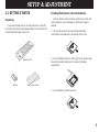 5
5
-
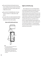 6
6
-
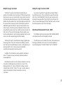 7
7
-
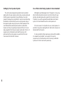 8
8
-
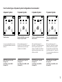 9
9
-
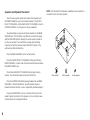 10
10
-
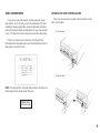 11
11
-
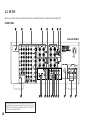 12
12
-
 13
13
-
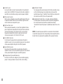 14
14
-
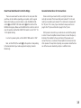 15
15
-
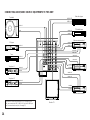 16
16
-
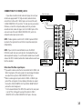 17
17
-
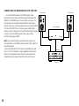 18
18
-
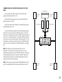 19
19
-
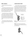 20
20
-
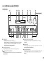 21
21
-
 22
22
-
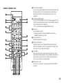 23
23
-
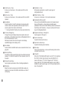 24
24
-
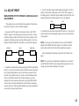 25
25
-
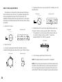 26
26
-
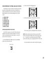 27
27
-
 28
28
-
 29
29
-
 30
30
-
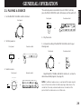 31
31
-
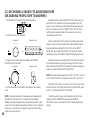 32
32
-
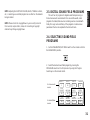 33
33
-
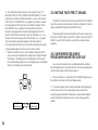 34
34
-
 35
35
-
 36
36
-
 37
37
-
 38
38
-
 39
39
-
 40
40
-
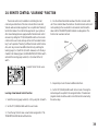 41
41
-
 42
42
-
 43
43
-
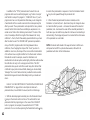 44
44
-
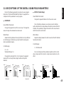 45
45
-
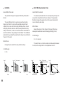 46
46
-
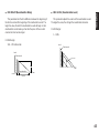 47
47
-
 48
48
-
 49
49
-
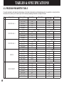 50
50
-
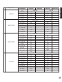 51
51
-
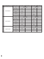 52
52
-
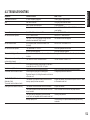 53
53
-
 54
54
-
 55
55
-
 56
56


Yamaha DSP-A2070 El manual del propietario
- Categoría
- Receptores AV
- Tipo
- El manual del propietario
en otros idiomas
- français: Yamaha DSP-A2070 Le manuel du propriétaire
- italiano: Yamaha DSP-A2070 Manuale del proprietario
- English: Yamaha DSP-A2070 Owner's manual
- Deutsch: Yamaha DSP-A2070 Bedienungsanleitung
- русский: Yamaha DSP-A2070 Инструкция по применению
- Nederlands: Yamaha DSP-A2070 de handleiding
- português: Yamaha DSP-A2070 Manual do proprietário
- dansk: Yamaha DSP-A2070 Brugervejledning
- polski: Yamaha DSP-A2070 Instrukcja obsługi
- čeština: Yamaha DSP-A2070 Návod k obsluze
- svenska: Yamaha DSP-A2070 Bruksanvisning
- Türkçe: Yamaha DSP-A2070 El kitabı
- suomi: Yamaha DSP-A2070 Omistajan opas
- română: Yamaha DSP-A2070 Manualul proprietarului
Artículos relacionados
-
Yamaha DSP-A1092 El manual del propietario
-
-
-
-
-
Yamaha 580 El manual del propietario
-
-
-
-