Dyna-Glo BF20NMDG Guía de instalación
- Categoría
- Calentadores espaciales
- Tipo
- Guía de instalación
Este manual también es adecuado para

1
VENT-FREE
BLUE FLAME
GAS WALL HEATER
INSTALLER: Leave this manual with the appliance.
CONSUMER: Retain this manual for future reference.
WARNING: IF THE INFORMATION IN THIS MANUAL IS NOT FOLLOWED
EXACTLY, A FIRE OR EXPLOSION MAY RESULT CAUSING PROPERTY
DAMAGE, PERSONAL INJURY OR LOSS OF LIFE.
WARNING: This appliance is equipped for
(natural or propane) gas. Field conversion is not
permitted.
- Do not store or use gasoline or other ammable vapors and Iiquids in vicinity of this or
any other appliance.
WHAT TO DO IF YOU SMELL GAS
• Do not try to light any appliance.
• Do not touch any electrical switch; do not use any phone in your building.
• Immediately call your gas supplier from a neighbor’s phone. Follow the gas supplier’s
instructions.
• If you cannot reach your gas supplier, call the re department.
- Installation and service must be performed by a qualied installer, service agency or the
gas supplier.
This is an unvented gas-red heater. It uses air (oxygen) from the room in which it is
installed. Provisions for adequate combustion and ventilation air must be provided.
Refer to Air For Combustion and Ventilation section on page 8 of this manual.
This appliance may be installed in an aftermarket, permanently located, manufactured (mobile)
home, where not prohibited by local codes.
This appliance is only for use with the type of gas indicated on the rating plate.
This appliance is not convertible for use with other gases.
C US
C US
ANS Z21.11.2-2013
Gas Fired Room Heaters
Volume II - Unvented Room Heaters
IMBF - 2018-03-21
MODEL #
Questions, problems, missing parts? Before returning to your retailer, call our customer
service department at 1-877-447-4768,
8:30 a.m. – 4:30 p.m., CST, Monday – Friday or
email us at [email protected].
Propane
BF10PTDG/PMDG
BF20PTDG/PMDG
BF30PTDG/PMDG
Natural Gas
BF10NTDG/NMDG
BF20NTDG/NMDG
BF30NTDG/NMDG


2
WARNING: Read the Installation & Operating Instructions before using this appliance.
IMPORTANT: Read all instructions and warnings carefully before starting installation.
Failure to follow these instructions may result in possible injury to persons or a re
hazard and will void the warranty.
TABLE OF CONTENTS
Important Safety Information ............................................................................................................3
Product Features
..............................................................................................................................6
Air For Combustion and Ventilation
.................................................................................................. 8
Installation
...................................................................................................................................... 11
Operation
........................................................................................................................................18
Care and Maintenance
...................................................................................................................22
Troubleshooting
..............................................................................................................................23
Replacement Parts
.........................................................................................................................27
Warranty
......................................................................................................................................... 28
PRODUCT SPECIFICATIONS
SERIES
BF10PTDG/PMDG BF20PTDG/PMDG
MAX BTU 10,000 20,000
MIN BTU 8,000 16,000
Fuel Type Propane Propane
Ignition
Electronic Push Button Electronic Push Button
Manifold Pressure 10 in. W.C. 10 in. W.C.
Inlet Gas Pressure
Maximum 14 in. W.C. 14 in. W.C.
*Minimum (*For purposes of input adjustment) 11 in. W.C. 11 in. W.C.
Dimensions (in.)
( H x W x D) (Height includes legs)
20.00 in. x 17.32 in. x 9.49 in 24.02 in. x 20.94 in. x 10.08 in.
Fan Ratings (Select Models) 120V/60Hz,18W, 0.15A 120V/60Hz,18W, 0.15A
SERIES BF30PTDG/PMDG
MAX BTU 30,000
MIN BTU 24,000
Fuel Type Propane
Ignition Electronic Push Button
Manifold Pressure 10 in. W.C.
Inlet Gas Pressure
Maximum 14 in. W.C.
*Minimum (*For purposes of input adjustment) 11 in. W.C.
Dimensions (in.)
( H x W x D) (Height includes legs)
24.09 in. x 28.07 in. x 10.51 in.
Fan Ratings (Select Models) 120V/60Hz,18W, 0.15A

3
SERIES BF30NTDG/NMDG
MAX BTU 30,000
MIN BTU 15,000
Fuel Type Natural Gas
Ignition Electronic Push Button
Manifold Pressure 5 in. W.C.
Inlet Gas Pressure
Maximum 14 in. W.C.
*Minimum (*For purposes of input adjustment) 6 in. W.C.
Dimensions (in.)
( H x W x D) (Height includes legs)
24.09 in. x 28.07 in. x 10.51 in.
Fan Ratings (Select Models) 120V/60Hz,18W, 0.15A
SERIES BF10NTDG/NMDG BF20NTDG/NMDG
MAX BTU 10,000 20,000
MIN BTU 5,000 10,000
Fuel Type Natural Gas Natural Gas
Ignition Electronic Push Button Electronic Push Button
Manifold Pressure 5 in. W.C. 5 in. W.C.
Inlet Gas Pressure
Maximum 14 in. W.C. 14 in. W.C.
*Minimum (*For purposes of input adjustment) 6 in. W.C. 6 in. W.C.
Dimensions (in.)
( H x W x D) (Height includes legs)
20.00 in. x 17.32 in. x 9.49 in. 24.02 in. x 20.94 in. x 10.08 in.
Fan Ratings (Select Models) 120V/60Hz,18W, 0.15A 120V/60Hz,18W, 0.15A

4
IMPORTANT: Read this owner’s manual carefully and completely before trying to assemble, operate,
or service this heater. Improper use of this heater can cause serious injury or death from burns, re,
explosion, electrical shock, and carbon monoxide poisoning.
IMPORTANT SAFETY INFORMATION
Installation and repair should be done by a qualied service person. The appliance should be
inspected before use and at least annually by a professional service person. More frequent
cleaning may be required due to excessive lint from carpeting, bedding material, etc. It
is imperative that control compartments, burners and circulating air passageways of the
appliance be kept clean.
WARNING: Any change to this heater or its controls can be dangerous.
WARNING: Carefully supervise young children when they are in the room with the heater.
WARNING: Heater becomes very hot when operating. Children and adults should be alerted
to the hazard of high surface temperatures and should stay away to avoid burns or clothing
ignition
Heater will remain hot for a time after shutoff. Allow surfaces to cool before touching.
WARNING: Make sure any panel, safety screen or guard removed for servicing an appliance
is replaced prior to operating the heater
WARNING: Keep the appliance area clear and free from combustible materials, gasoline, and
other ammable vapors and liquids.
WARNING: Do not place clothing or other ammable material on or near the appliance. Never
place any objects on the heater.
WARNING: Due to high temperatures, locate this appliance out of trafc and away from
furniture and draperies.
This appliance is intended for supplemental heating.
CARBON MONOXIDE POISONING: Early signs of carbon monoxide poisoning resemble the u with
headaches, dizziness, or nausea. If you have these signs, the heater may not be working properly. Get
fresh air immediately! Have heater serviced. Some people are more affected by carbon monoxide than
others. These include pregnant women, people with heart or lung disease, people who are
anemic, those under the inuence of alcohol, and those living in high altitudes.
NATURAL AND PROPANE/LP GAS: Natural and Propane/LP gases are odorless. An odor-making
agent is added to the gas. The odor helps you detect a gas leak. However, the odor added to the gas
can fade. Gas may be present even though no odor exists. Make certain you read and understand all
warnings. Keep this manual for reference. It is your guide to operating this heater safely.
If the heater is being installed in a residential garage, it must be secured rmly to the
wall, a minimum of 18 in. (457mm) above the oor. The heater must be located so that it
is protected against any possibility of damage by a moving vehicle, etc.
Raising the heater will reduce BUT NOT eliminate the possibility of lighting the vapor of any
ammable liquids which may be improperly stored or accidentally spilled. If the smell of
gasoline is present, do not operate this heater until the area has been properly ventilated.
WARNING:

5
WARNING: Do not use any accessories not approved for use with this heater.
SAFETY INFORMATION
1. Do not place Propane/LP supply tank(s) inside any structure. Place Propane/LP supply tank(s)
outdoors.
2. Only the BF10 series can be installed in a bedroom. When installing in a bedroom
the heater MUST be mounted to the wall (See Wall Mounting, Page 14). All other models cannot
be installed in a bedroom. These units are not approved for bathroom use.
3. This heater needs fresh air ventilation to run properly. This heater has an Oxygen Depletion Sensing
(ODS) safety shutoff system. The ODS shuts down the heater if not enough fresh air is available.
See Air for Combustion and Ventilation, pages 7 through 9. If heater keeps shutting off, see
Troubleshooting, pages 22 through 25.
4. Keep all air openings in front, top and bottom of heater free of objects and debris to ensure
adequate air for proper combustion.
5. If heater shuts off, do not relight until you have provided fresh, outside air. If heater keeps shutting
off, have it serviced.
6. Do not run heater:
• Where ammable liquids or vapors are used or stored.
• Under dusty conditions.
7. Before using furniture polish, wax, carpet cleaner, or similar products, turn heater and pilot off. If
heated, the vapors from these products may create a white powder residue within burner box or
on adjacent walls or furniture.
8. Do not use heater if any part has been under water. Immediately call a qualied service technician
to inspect the room heater and to replace any part of the control system and any gas control
which has been under water.
9. Turn off and unplug heater and let cool before servicing. Only a qualied service person should
service and repair heater.
10. To prevent performance problems, do not use propane/LP fuel tank of less than 100 lbs. capacity.
11. WARNING: Do not allow fans to blow directly into the heater. Avoid any drafts that alter
burner ame patterns.
12. WARNING: Do not operate heater if the tempered glass panel is not secured, broken, or
missing. Only replace the tempered glass panel with parts and/or components provided by
GHP Group, Inc.
13. SAVE THESE INSTRUCTIONS.
WARNING
This product and the fuels used to operate this product (liquid propane or natural gas), and the
products of combustion of such fuels, can expose you to chemicals including benzene, which is
known to the State of California to cause cancer and reproductive harm.
For more information go to www.p65Warnings.ca.gov

6
PRODUCT FEATURES
SAFETY PILOT
This heater has a pilot with an Oxygen Depletion Sensing (ODS) safety shutoff system.
The ODS/pilot shuts off the heater if there is not enough fresh air and cuts off main burner gas in the
event of ame out.
LEG KIT (SELECT MODELS)
2 support legs and 4 support leg screws are included for oor mounting the heater. See page 13.
NOTE: This is an optional accessory and is not required for operation of the heater.
ELECTRONIC PUSH BUTTON IGNITION SYSTEM
This heater is equipped with an electronic push button ignition system. This system requires
one AAA battery (provided).
THERMOSTAT HEAT CONTROL (SELECT MODELS)
The control automatically cycles the burner on and off to maintain a desired room
temperature. See page 24.
FAN KIT (SELECT MODELS)
The fan kit helps to distribute the warmed air into the space more rapidly.
NOTE: This is an optional accessory and is not required for operation of the heater.
State of Massachusetts: The installation must be made by a licensed plumber or gas tter in
the Commonwealth of Massachusetts. Sellers of unvented propane or natural gas-red
supplemental room heaters shall provide to each purchaser a copy of 527 CMR 30 upon sale
of the unit.
In the State of Massachusetts, unvented propane or natural gas-red space heaters shall
be prohibited in bedrooms and bathrooms.
In the State of Massachusetts the gas cock must be a T-handle type. The State of
Massachusetts requires that a exible appliance connector cannot exceed three feet
in length.
LOCAL CODES
Install and use heater with care. The installation must conform with local codes or, in the absence of
local codes, with the latest edition of The Nation Fuel Gas Code, ANSI Z223.1/NFPA 54
*Available from:
American National Standard Institute, Inc. National Fire Protection Association, Inc.
1430 Broadway 1 Batterymarch Park
New York, NY 10018 Quincy, MA 02269-9101
This heater is designed for vent-free operation. State and local codes in some areas prohibit, restrict
and or have special requirements for vent-free heaters.

7
PREPARING FOR INSTALLATION
Before beginning assembly or operation of the product, make sure all parts are present.
Compare parts with package contents list. If any part is missing or damaged, do not attempt
to assemble, install or operate the product. Contact customer service for replacement parts.
UNPACKING
1. Remove heater from carton.
2. Remove all protective packaging applied to heater for shipping
3. Verify all contents are present.
NOTE: Support Leg Screw (M4*15) (Select Models), Wood Screw (ST4.8*45-16),
Expansion Bracket Screw(ST4.8*15-16), and Expansion Bracket come with (2) extra each.
4. Check heater for any shipping damage. If heater is damaged, promptly inform dealer where you
bought the heater.
WATER VAPOR: A BY-PRODUCT OF UNVENTED ROOM HEATERS
Water vapor is a by-product of gas combustion. An unvented room heater produces
approximately one (1) ounce (30 mL) of water for every 1,000 BTUs (.3 Kw) of gas input
per hour. An unvented room heater is intended as a supplemental heater rather than a primary heat
source. In most supplemental heat applications, the water vapor does not create a problem.
In most applications, the water vapor enhances the low humidity atmosphere experienced during
cold weather.
The following steps will help ensure that water vapor does not become a problem:
1. Be sure the heater is the proper size for the application, including adequate combustion air and
circulation air.
2. If there is high humidity, a dehumidier may be used to help lower the water vapor content
of the air.
3. Do not use an unvented room heater as the primary heat source.
Expansion
Bracket x 4
Expansion Bracket
Screw (ST4.8*15-16) x 4
Wall Hanging
Spacer x 2
Wood Screw
(ST4.8*45-16) x 4
Expansion Bracket
Tool x 1
Wall Hanging
Spacer Screw
(M4*25) x 2
Wall Mounting
Bracket x 1
Support Leg Screw
(M4*15) x 4
(Select Models)
Support Leg x 2
(Select Models)
AAA Battery x 1

8
PREPARING FOR INSTALLATION
AIR FOR COMBUSTION AND VENTILATION
CAUTION: This heater shall not be installed in a room or space unless the required volume of
indoor combustion air is provided by the method described in the National Fuel Gas Code, ANSI
Z223.1/NFPA54, the International Fuel Gas Code, or applicable local codes.
PRODUCING ADEQUATE VENTILATION
All spaces in homes fall into one of the three following ventilation classications:
1. Unusually Tight Construction
2. Unconned Space
3. Conned Space
The information on pages 8 through 10 will help you classify your space and provide adequate ventilation.
Conned and Unconned Space
A conned space as a space whose volume is less than 50 cu. ft. per 1,000 BTU/hr (4.8 m^3 per kw)
of the aggregate input rating of all appliances installed in that space and an unconning space as a
space whose volume is not less than 50 cu. ft. per 1,000 BTU/hr (4.8 m^3 per kw) of the aggregate
input rating of all appliances installed in that space. Rooms connecting directly with the space in
which the appliances are installed*, through openings not furnished with doors, are considered a
part of the unconned space.
This heater shall not be installed in a conned space or unusually tight construction unless provisions
are provided for adequate combustion and ventilation air.
* Adjoining rooms are connecting only if there are doorless passageways or ventilation
grills between them.
Unusually Tight Construction
The air that leaks around doors and windows may provide enough fresh air for combustion and venti-
lation. However, in buildings of unusually tight construction, you must provide additional
fresh air.
Unusually tight construction is dened as construction where:
a) walls and ceilings exposed to the outside atmosphere have a continuous water vapor retarder
with a rating of one perm (6x10-11kg per pa-sec-m2) or less with openings gasketed or sealed
and
b) weather stripping has been added on windows that can be opened and on doors and
c) caulking or sealants are applied to areas such as joints around window and door frames,
between sole plates and oors, between wall-ceiling joints, between wall panels, at
penetrations for plumbing, electrical, and gas lines, and at other openings.
If your home meets all of the three criteria above, you must provide additional fresh air.
See “Ventilation Air From Outdoors” (page 10). If your home does not meet all of the
three criteria above, proceed to “Determining Fresh-Air Flow For Heater Location”.

9
PREPARING FOR INSTALLATION
DETERMINING FRESH-AIR FLOW FOR HEATER LOCATION
Determining if You Have a Conned or Unconned Space
Use this worksheet to determine if you have a conned or unconned space.
Space: Includes the room in which you will install heater plus any adjoining rooms with
doorless passageways or ventilation grills between the rooms.
1. Determine the volume of the space Length × Width × Height = cu. ft. (volume of space)
Example: Space size 20 ft. (length) × 16 ft.(width) × 8 ft. (ceiling height) = 2560 cu. ft. (volume
of space)
If additional ventilation to adjoining room is supplied with grills or openings, add the volume of these
rooms to the total volume of the space.
2. Divide the space volume by 50 cu. ft. to determine the maximum BTU/hr the space can support.
_______ (volume of space) ÷ 50 cu. ft.= (Maximum BTU/hr the space can support)
Example: 2560 cu. ft. (volume of space) ÷ 50 cu. ft. = 51.2 or 51,200 (maximum BTU/hr the space
can support)
3. Add the BTU/hr of all fuel burning appliances in the space.
Vent-free heater _________ BTU/hr
Gas water heater* ________BTU/hr
Gas furnace _____________BTU/hr
Vented gas heater ________BTU/hr Example:
Gas heater logs __________BTU/hr Gas water heater 30,000 BTU/hr
Other gas appliances*+ ____BTU/hr Vent-free heater + 26,000 BTU/hr
Total = ____BTU/hr Total = 56,000 BTU/hr
*Do not include direct-vent gas appliances. Direct-vent draws combustion air from the
outdoors and vents to the outdoors.
4. Compare the maximum BTU/hr the space can support with the actual amount of BTU/hr used.
_______ BTU/hr (maximum the space can support)
_______ BTU/hr (actual amount of BTU/hr used).
Example : 51,200 BTU/hr (maximum the space can support) 56,000 BTU/hr (actual amount of
BTU/hr used)
The space in the above example is a conned space because the actual BTU/hr used is more than
the maximum BTU/hr the space can support.
You must provide additional fresh air. Your options are as follows:
a) Rework worksheet, adding the space of an adjoining room. If the extra space provides an
unconned space, remove door to adjoining room or add ventilation grills between rooms. See
“Ventilation Air From Inside Building,” page 10.
b) Vent room directly to the outdoors. See “Ventilation Air From Outdoors”, page 10.
c) Install a lower BTU/hr heater if lower BTU/hr size makes room unconned. If the actual BTU/hr
used is less than the maximum BTU/hr the space can support, the space is an unconned space.
You will need no additional fresh air ventilation.

10
PREPARING FOR INSTALLATION
Ventilation Air From Inside Building
This fresh air would come from adjoining
unconned space. When ventilating to an
adjoining unconned space, you must
provide two permanent openings: one
within 12 in. of the wall connecting
the two spaces (see options 1 and 2,
Fig. 1). You can also remove door into
adjoining room (see option 3, Fig. 1).
Follow the National Fuel Gas Code
NFPA 54/ANS Z223.1. Air for Combustion
and Ventilation for required size of
ventilation grills or ducts.
Ventilation Air From Outdoors
Provide extra fresh air by using ventilation
grills or duct. You must provide two
permanent openings: one within 12 in. of
the ceiling and one within 12 in. of the oor.
Connect these items directly to the outdoors
or spaces open to the outdoors. These
spaces include attics and crawl spaces.
Follow the National Fuel Gas Code NFPA
54/ANS Z223.1. Air for Combustion and
Ventilation for required size of ventilation
grills or ducts.
IMPORTANT: Do not provide openings for
inlet or outlet air into attic if attic has a
thermostat-controlled power vent. Heated
air entering the attic will activate the power
vent. Rework worksheet, adding the space
of the adjoining unconned space. The
combined spaces must have enough fresh
air to supply all appliances in both spaces.

11
INSTALLATION
NOTICE: This heater is intended for use as supplemental heat. Use this heater along with your
primary heating system. Do not install this heater as your primary heat source.
WARNING: A qualied technician must install heater. Follow all local codes.
WARNING: Maintain the minimum clearances. If possible, provide greater clearances from the
oor, ceiling, and adjoining wall than required.
CAUTION: This heater creates warm air currents. These currents move heat to wall surfaces
next to heater. Installing heater next to vinyl or cloth wall coverings or operating heater where
impurities (such as tobacco smoke, candles, cleaning uids, oil or kerosene lamps, etc.)
in the air exist, may cause walls to discolor.
CLEARANCES TO COMBUSTIBLES
Carefully follow the instructions below. This heater can be mounted on the wall or on the oor using
the support legs (Select Models).
WARNING: Maintain the minimum clearances shown in (See Fig. 3). If you can, provide greater
clearances from oor, ceiling, and joining wall.
Fig. 3 - Mounting clearances as viewed from
front of heater (inches)
Always maintain a minimum of 36 in. clearance from furniture and draperies.
*A second side wall must be at least 18 in. away from the other side of the heater.
*LEFT/RIGHT TOP BOTTOM FRONT Rear
8in. 36in. 3in. 36in. 0in.toSpacer
Topclearanceisfromtopofheatertoceiling,woodshelforothercombustiblematerial
Bottomclearanceisfrombottomofheatertosurfaceofcarpet,tileorothercombustiblematerial.
MINIMUMCLEARANCETOCOMBUSTIBLES
*For the installation in residential garages please refer to the bottom of page 3.
RIGHT SIDE
36 in.
Minimum
CEILING
8 in.
Minimum
From
Side of
Heater
LEFT SIDE
36 in. Minimum from
Furniture and Draperies
FRONT
3 in. Minimum to Top Surface of Carpeting,
Tile or Other Combustible Material
FLOOR
*A Second Side Wall Must be at Least 18in.
Away from the Other Side of the Heater.

12
INSTALLATION
INSTALLING IGNITOR BATTERY
• Battery is included.
• Unscrew ignitor cap and insert included battery negative (at)
side down (See Fig. 7). Replace Ignitor cap.
• Be sure to observe proper polarity (+/-) when installing or re-
placing the battery. Damage due to improper battery installa-
tion may void the warranty on the product.
• Install/replace the battery according to the type and quantity
stated in table below.
• Remove battery when depleted.
• For long periods of non-operation, remove the battery from all
components for safety.
WARNING: Do not use rechargable silver oxide cell batteries.
Do NOT dispose of batteries in re. Improper disposal may
cause batteries to leak or explode.
Component Type of Battery Battery Qty.
Ignitor AAA 1
Fig. 7 - Installing Ignitor Battery
INSTALLING FAN (OPTIONAL)
WARNING: Electrical Grounding Instructions
This appliance is equipped with a three-prong (grounding) plug
for your protection against shock hazard and should be plugged
directly into a properly grounded three-prong receptacle (See Fig. 8).
1. Wall mounted heater must be disconnected from gas supply and
removed from wall before installing fan accessory. Contact a
qualied service person to do this.
2. Remove fan knock-out panel using a screwdriver (See Fig. 9).
Attach Fan to the rear panel of the heater using the four
screws provided.
NOTE: Be sure the rocker switch is positioned in the upper right
corner. (See Fig. 10).
3. This fan is equipped with manual “MAN” and automatic “AUTO”
settings (See Fig. 11 on page 13). Set the rocker switch to “MAN”
for manual mode, allowing the fan to continuously run until the
rocker switch is returned to the OFF “O” position. Set the rocker
switch to “AUTO” for the automatic mode, which will turn the fan on
and off based on ambient room temperature. It may take 5 to 10
minutes for the fan to come on when the unit is cold.
NOTE: If any of the original wire as supplied with the appliance must
be replaced, it must be replaced with a wire of at least an equal tem-
perature rating. Refer to Fig. 12 on page 13 for wiring diagram.
CAUTION: Label all wires prior to disconnection when servicing
controls. Wiring errors can cause improper and dangerous opera-
tion. Verify proper operation after servicing.
Fig. 8 - Fan Electric Supply
Fig. 9 - Knock-out Panel
Fig. 10 - Attaching Fan
Grounded Three-Prong
Receptacle
Rocker Switch

13
INSTALLATION
MAN AUTO
Fan Switch
Thermo-switch
Fan
White
Black
Green
110/115
VAC
Wiring Diagram
Fig. 12- Fan Wiring Diagram
MAN AUTO
Fig. 11 - Operating Fan
LOCATING HEATER
This heater is designed to be mounted on a wall or on
a oor, using the Support Legs (Select Models) includ-
ed with select models.
For convenience and efciency, install heater:
1. Where there is easy access for operation,
inspection, and service.
2. In the coldest part of room.
3. A minimum of 3' away from furniture and draperies.
FLOOR MOUNTING (Select Models)
(Cannot be done in bedroom or bathroom)
(Cannot be used for garage and ice-house heaters)
NOTE: This is an optional accessory and is not
required for operation of the heater.
Before installing Support Legs to heater base, please
make sure you have the following items:
(2) Support Legs
(4) Support Leg Screws (M4*15)
1. Set down a blanket onto the table where the heater
will be placed for leg installation to prevent scratch-
ing of the table and/or the heater.
2. Set back of heater on table with the bottom of heater
extending outside the table edge.
3. Fasten Support Legs to heater using Support Leg
Screws (Fig.13)
Note: If the heater is to be installed directly on carpet-
ing, tile or other combustible material, other than
wood ooring, the appliance shall be installed on a
metal or wood panel extending the full width and
depth of the appliance.
3. Once positioned, secure heater to the oor
using Support Leg Screws (M4*15) and mounting holes
found on heater Support Legs (See Fig. 14).
WALL MOUNTING
WARNING: Failure to position the parts in
accordance with these diagrams or failure to use only
parts specically approved with this heater may result in
property damage or personal injury.
Mounting Bracket
The mounting bracket is located separately from the
unit, but packed inside the same box.
Support Leg
Fig. 14 - Securing Support Leg
Fan Rocker
Switch
Rocker Switch
Fig. 13 - Attaching Legs
Support Leg
Screw
Support Leg

14
INSTALLATION
Fig. 16 - Mounting Bracket
Clearances (inches)
Series BF10
Methods For Attaching Mounting Bracket To Wall
Use only the last hole on each end of mounting bracket to attach bracket to wall. Attach
mounting bracket to a wall only in one of two ways:
1. Attaching to wall stud: This method provides the strongest hold. Insert wood screws (ST.8*45-16)
through mounting bracket and into wall studs.
2. Attaching to expansion bracket: This method allows you to attach mounting bracket to hollow
walls (wall areas between studs) or to solid walls (concrete or masonry).
Decide which method better suits your needs. Either method will provide a secure hold for the
mounting bracket.
Marking Screw Locations
1. Tape mounting bracket to wall where heater
will be located. Make sure mounting bracket
is level.
2. Mark screw locations on wall (See Fig. 16).
Note: Mark only last hole on each end of
mounting bracket. Insert (2) wood screws
(ST.8*45-16) total through these holes only.
3. Remove tape and mounting bracket
from wall.
Attaching Mounting Bracket To Wall
Note: Expansion bracket, wood screws (ST.8*45-16),
and wall hanging spacers are in hardware package.
The hardware package is provided with heater.
Attaching to Wall Stud Method
For attaching mounting bracket to wall studs:
1. Drill holes at marked locations using
9/64-inch drill bit.
2. Place mounting bracket onto wall. Line up last hole
on each end of bracket with holes drilled in wall.
3. Insert wood screws (ST.8*45-16) through bracket
and into wall studs.
4. Tighten wood screws (ST.8*45-16) until mounting
bracket is rmly fastened to wall studs.
5. Check that the bracket is secure before mounting
heater!
Series BF20/30

15
INSTALLATION
Fig. 18 - Popping Open Anchor
Wing For Thin Walls
Attaching to Expansion Bracket Method
For attaching mounting bracket to hollow walls (wall
areas between studs) or solid walls (concrete or ma-
sonry):
1. Drill holes at marked locations using 5/16-inch drill bit.
For solid walls (concrete or masonry), drill at least
1 inch deep.
2. Fold wall expansion bracket as shown in (See Fig. 17).
3. Insert wall expansion bracket (wings rst) into hole. Tap
expansion bracket ush to wall.
4. For thin walls (1/2 inch or less), insert expansion
bracket tool into expansion bracket. Push expansion
bracket tool to “pop” open expansion bracket wings
(See Fig. 18).
IMPORTANT: Do not hammer expansion bracket tool!
For thick walls (over 1/2 inch thick) or solid walls, do not
pop open wings.
5. Place mounting bracket onto wall. Line up last hole on
each end of bracket with expansion bracket.
6. Insert expansion bracket screws (ST4.8*15-16) through
wall mounting bracket and into expansion brackets.
7. Tighten expansion bracket screws (ST4.8*15-16) until
mounting bracket is rmly fastened to wall.
8. Check that the bracket is secure before mounting
heater!
Attaching Wall Hanging Spacers to Heater
WARNING: Failure to properly install the wall hanging
spacers may result in property damage, personal injury
or even death.
1. Locate spacer mounting holes on the lower right/left
sections of the heater back panel.
2. Secure (2) wall hanging spacers to heater back panel
using (2) wall hanging spacer screws (M4*25) (See Fig.
19a).
Placing Heater On Mounting Bracket
1. Locate two horizontal slots on back panel of heater.
2. Place heater onto mounting bracket. Slide horizontal
slots onto stand-out tabs on mounting bracket. Be sure
spacers rest evenly against wall (See Fig. 19b).
Fig. 17 - Folding the
Expansion Bracket
Fig. 19b - Mounting Heater
Onto Mounting Bracket
Horizontal Slots
Fig. 19a - Attaching Wall
Hanging Spacers to Heater
Spacers

16
INSTALLATION
CONNECTING TO GAS SUPPLY
WARNING: A qualied service technician must connect heater to gas supply. Follow all local
codes.
IMPORTANT: This appliance requires a 3/8-inch NPT (National Pipe Thread) inlet connection to
the pressure regulator. Never connect the heater to private (non-utility) gas wells, commonly
known as wellhead gas.
WARNING: Do not overtighten gas connections.
CAUTION: Use only new, black iron or steel pipe. Internally tinned copper tubing may be used
in certain areas. Check your local codes. Use pipe of 1/2-in. diameter or greater to allow proper
gas volume to heater. If pipe is too small, undue loss of pressure will occur.
CAUTION: Check your gas line pressure before connecting heater to gas line. Gas line pressure
must be a minimum 6'' WC for NG & 11" WC for LP with a max pressure of 9'' WC for NG & 14"
WC for LP. If gas line pressure is higher, the unit will not work and heater regulator damage could
occur.
CAUTION: Never connect heater directly to an LP supply. This heater requires an external
regulator (not supplied). Install the external regulator between the heater and gas supply.
CAUTION: Avoid damage to regulator. Hold gas regulator with wrench when connecting into gas
piping and/or ttings.
CAUTION: Use pipe joint sealant that is resistant to gas (Propane or Natural Gas).
Typical Inlet Pipe Diameters
Use 3/8-inch black iron pipe or greater. Installation must include an equipment shutoff valve, union,
and plugged 1/8-inch NPT tap.
Locate NPT tap within reach for test gauge hook up. NPT tap must be upstream from heater
(see Fig. 20).
IMPORTANT: Install an equipment shutoff valve in an accessible location. The equipment shutoff
valve is for turning on or shutting off the gas to the appliance.
Apply pipe joint sealant lightly to male threads. This will prevent excess sealant from going
into pipe. Excess sealant in pipe could result in clogged heater valves.

17
INSTALLATION
Install sediment trap in supply line as shown
(See Fig. 20). Place sediment trap where it is
within reach for cleaning. Place sediment trap
where trapped matter is not likely to freeze. A
sediment trap traps moisture and contaminants.
This keeps them from going into heater controls.
If sediment trap is not installed or is installed
wrong, heater may not run properly.
Fig. 20 - Gas Connection
CHECKING GAS CONNECTIONS
WARNING: Test all gas piping and connections for leaks after installing or servicing. Correct all
leaks immediately.
WARNING: Never use an open ame to check for a leak. Apply a 50/50 mixture of liquid soap and
water to all joints. If bubbles form, there may be a leak. Correct all leaks immediately.
Pressure Testing Gas Supply Piping System
Test Pressures In Excess Of 1/2 PSIG ( 3.5kPa )
The appliance and its appliance main gas valve must be disconnected from the gas supply piping
system during any pressure testing of that system at test pressures in excess of ½ psi (3.5 kPa).
Pressure Testing Gas Supply Equal To or less than
1/2 PSIG ( 3.5kPa )
The appliance must be isolated from the gas supply piping system by closing its equipment shut-off
valve during any pressure testing of the gas supply piping system at test pressures equal to or less
than
½ psi (3.5 kPa).
Leak Testing Heater Gas Internal Connections
1. Open equipment shutoff valve (See Fig. 21).
2. Make sure control knob of heater is in the OFF position.
3. Open gas supply tank valve (LP systems).
4. Check all joints from equipment shutoff valve to control
valve. Apply 50/50 mixture of
liquid soap and water to gas joints. If bubbles form, there
may be a leak.
5. Light heater (see Operation, page 18). Check all other
internal joints for leaks.
6. Turn off heater (see "To Turn Off Gas to Appliance,"
page 19).
Fig. 21 - Equipment Shut -off Valve

18
OPERATION
FOR YOUR SAFETY READ BEFORE LIGHTING
WARNING: If you do not follow these instructions exactly, a re or explosion may result
causing property damage, personal injury or loss of life.
A. This appliance has a pilot which must be lighted using the Ignitor. When lighting the pilot,
follow these instructions exactly.
B. BEFORE LIGHTING smell all around the appliance area for gas. Be sure to smell next to the oor
because some gas is heavier than air and will settle on the oor.
WHAT TO DO IF YOU SMELL GAS
• Do not try to light any appliance.
• Do not touch any electrical switch; do not use any phone in your building.
• Immediately call your gas supplier from a neighbor’s phone. Follow the gas supplier’s instructions.
• If you cannot reach your gas supplier, call the re department.
C. Use only your hand to push in or turn the gas control knob. Never use tools. If the knob will not
push in or turn by hand, don't try to repair it, call a qualied service technician. Forced or
attempted repair may result in a re or explosion.
D. Do not use this appliance if any part has been under water. Immediately call a qualied service
technician to inspect the appliance and to replace any part of the control system and any gas
control, which has been under water.
LIGHTING INSTRUCTIONS
MANUAL GAS CONTROL
1. STOP! Read the safety information above on this page.
2. Turn off all electric power to the appliance.
3. Push in gas control knob slightly and turn clockwise to
OFF " " position. (See Fig. 22a)
NOTE: Knob cannot be turned from PILOT " " to OFF " " unless knob
is pushed in slightly. Do not force.
4. Wait (5) minutes to clear out any gas. Then smell for gas, including
near the oor. If you smell gas, STOP! Follow “B” in the safety
information above. If you don’t smell gas, go to the next step.
5. Push in gas control knob slightly and turn counterclockwise to the
PILOT " " position. (See Fig. 23a) Depress control knob.
6. With control knob depressed, push down on the ignitor button
until the pilot lights. The pilot is visible centered below the
plaques, behind the front grill. (See Fig. 24)
7. Keep control depressed for (30) seconds after pilot lights. Release
control knob.
Note: If pilot goes out repeat steps 3 through 7. Wait (1) minute before
attempting to light pilot again.
If after several tries the pilot still goes out, turn the gas control knob
clockwise to the OFF " " position and call your service technician or gas supplier.
Fig. 22a
Fig. 23a

19
OPERATION
THERMOSTAT GAS CONTROL
1. STOP! Read the safety information on the previous page.
2. Turn off all electric power to the appliance.
3. Turn control knob clockwise to "OFF" position. (See Fig. 22b)
4. Wait (5) minutes to clear out any gas. Then smell for gas, including
near the oor. If you smell gas, STOP! Follow “B” in the safety
information above. If you don’t smell gas, go to the next step.
5. Turn knob counterclockwise to the "PILOT" position.
(See Fig. 23b) Depress control knob.
6. With control knob depressed, push down on the ignitor button
until the pilot lights. The pilot is visible centered below the
plaques, behind the front grill. (See Fig. 24)
7. Keep control depressed for (30) seconds after pilot lights. Release
control knob.
Note: If pilot goes out repeat steps 3 through 7. Wait (1) minute before
attempting to light pilot again. If after several tries the pilot still goes out,
turn the gas control knob clockwise to the "OFF" position and call
your service technician or gas supplier. If the control knob does not pop up
when released, stop and immediately and call your service technician or
gas supplier.
8. Turn on all electric power to the appliance.
9. Turn control knob counter clockwise to desired setting.
1
2
3
4
5
O
F
F
P
I
L
O
T
1
2
3
4
5
O
F
F
P
I
L
O
T
Fig. 22b
Fig. 23b
Fig. 24 - Pilot Flame Location
LIGHTING INSTRUCTIONS
If the control knob does not pop up when released, stop and immediately and call your service
technician or gas supplier.
8. Turn on all electric power to the appliance.
9. Turn control knob counter clockwise to the desired setting.
TO TURN OFF GAS TO APPLIANCE
1. Turn off all electric power to the appliance if service is to be performed.
2. Push in gas control knob slightly and turn clockwise to "OFF" or " " position.
DO NOT FORCE.

20
THERMOSTATIC CONTROL OPERATION (SELECT MODELS)
The thermostat used on this heater senses the room tempera-
ture. At times the room may exceed the set temperature. If so,
the burner will shut off. The burner will cycle back on when
room temperature drops below the set temperature. The control
knob can be set to any comfort level between "HIGH" (5) and
"LOW"(1) (See Fig. 25).
MANUAL CONTROL OPERATION
Manual valves remain burning in the desired setting until manu-
ally turned to OFF " "(See Fig. 25).
Fig. 25 - Control
Knob Position
ManualThermostatic
OPERATION
INSPECTING BURNERS
Check pilot ame pattern daily when in use and at least yearly by a qualied service agency.
PILOT FLAME PATTERN
Fig. 26 shows a correct pilot ame pattern. Fig. 27 shows an incorrect pilot ame pattern. The incor-
rect pilot ame is not touching the thermocouple. This will cause the thermocouple to cool, which
shuts the heater off. If pilot ame pattern is incorrect:
• turn heater off (see “To Turn Off Gas to Appliance” on page 19)
• see Troubleshooting pages 23 through 26.
Fig. 26 - Correct Pilot Flame Pattern Fig. 27 - Incorrect Pilot Flame Pattern
1
2
3
4
5
O
F
F
P
I
L
O
T

21
OPERATION
BURNER FLAME PATTERN
Fig. 28 shows a correct burner ame pattern. Fig. 29 shows an incorrect burner ame pattern with
lifting, and excessive ame height.
If burner ame is incorrect:
• turn heater off (see “To Turn Off Gas to Appliance”, page 20).
• see Troubleshooting, pages 23 through 26.
1/2 Glass
Height
1/2 Glass
Height
NOTE: Ambient ame burners produce both a blue and yellow ame. An excessively high yel-
low colored ame may be caused by airborne dust, dander, pet hair, etc. Additionally, an excess
amount of Mercaptane in the fuel can result in an orange or yellow colored ame.
The upper third of ame
may be bright yellow when
operated on propane.
When this heater is set for use on propane gas, the upper one third of the ame may be bright yellow.
When this heater is set for use on natural gas, a slight yellow tipping of the ame may occur.
Fig. 28 - Correct/Normal Flame Pattern
with short ames with Control Knob Set
to High Flame (5)
Fig. 29 - Incorrect/Abnormal Flame Pat-
tern with tall ames with Control Knob
Set to High Flame (5)

22
NOTE: Before servicing you will need to remove the front panel of the
heater. There are 4 Philips head screws, 2 on the left side and 2 on the
right, securing the front panel to the heater (See Fig. 30). Always allow
the unit to cool for at least thirty minutes before attempting to remove the
front panel.
WARNING: Turn off heater, unplug electrical cord and let cool
before servicing.
CAUTION: You must keep control areas, burner, and circulating air
passageways of heater clean. Inspect these areas of heater before
each use. Have heater inspected yearly by a qualied service
person. Heater may need more frequent cleaning due to excessive
lint from carpeting, bedding material, pet hair, etc.
WARNING: Failure to keep the primary air opening(s) of the burner(s) clean may result in sooting
and propery damage.
CLEANING ODS/PILOT AND BURNER
Use a vacuum cleaner, pressurized air, or a small, soft bristled brush to clean burner ports, orice and
primary burner. Look into burner opening and ensure that it is clean.
CLEANING BURNER PILOT AIR INLET HOLE
We recommend that you clean the unit every three months or after 2,500 hours of operation. We also
recommend that you keep the burner tube and pilot assembly clean and free of dust and dirt. To clean
these parts we recommend using compressed air no greater than 30 PSI. You can use a vacuum
cleaner in the blow position. If using compressed air in a can, please follow the directions on the can.
If you don't follow directions on the can, you could damage the pilot assembly.
1. Shut off the unit, including the pilot. Allow the unit to cool for at least thirty minutes.
2. Remove 4 screws - 2 screws on each side of the front panel.
3. Pull front panel forward.
4. Blow air through the ports/slots and holes in the burner. Also clean the pilot assembly. A yellow
tip on the pilot ame indicates dust and dirt in the pilot assembly. There is a small pilot air inlet hole
about two inches from where the pilot ame comes out of the pilot assembly (see Fig. 26 & 27 on
page 19). With the unit off, lightly blow air through the air inlet hole. You may blow through a
drinking straw if air is not available.
5. Replace front panel when completed, using the screws removed.
CLEANING GLASS
Use mild soap and water. Avoid using abrasive cleaners which can scratch the glass. The tempered
glass installed on this product contains a “Low E” coating on the interior surface. If the glass is re-
moved, you must ensure the “Low E” coated side is installed on the interior side, facing the burner
assembly.
CLEANING CABINET AIR PASSAGEWAYS
Use a vacuum cleaner or pressurized air to clean.
CLEANING FAN (Select Models)
Carefully use a vacuum cleaner or compressed air to keep fan compartment and blades free of dust
and debris.
NOTE: The fan motor is pre-lubricated for extended bearing life and requires no further lubrication.
CLEANING EXTERIOR
Use a soft cloth dampened with a mild soap and water mixture.
Wipe the cabinet to remove dust.
CARE AND MAINTENANCE
Fig. 30 - Front Panel Removal
CAUTION: Never use a wire, needle, or similar object to clean ODS/pilot. This can damage ODS/ pilot unit.

23
CAUTION: Never use a wire, needle, or similar object to clean ODS/pilot. This can damage ODS/ pilot unit.
TROUBLESHOOTING
WARNING: If you smell gas:
• Shut off gas supply.
• Do not try to light any appliance.
• Do not touch any electrical switch; do not use any phone in your building.
• Immediately call your gas supplier from a neighbor’s phone. Follow the gas supplier’s instructions.
• If you cannot reach your gas supplier, call the re department.
IMPORTANT: Operating heater where impurities in air exist may create odors. Cleaning supplies,
paint, paint remover, cigarette smoke, cements and glues, new carpet or textiles, etc., create fumes.
These fumes may mix with combustion air and create odors.
WARNING: Make sure that power is turned off before proceeding.
WARNING: Turn off and let cool before servicing. Only a qualied service person should service
and repair heater.
PROBLEM POSSIBLE CAUSE CORRECTIVE ACTION
When Ignitor is
pressed in, there is
no spark at ODS/
pilot.
1. Ignitor electrode is
positioned wrong.
2. Ignitor electrode is broken.
3. Ignitor electrode is not
connected to ignitor cable.
4. Ignitor cable is pinched or
wet.
5. Damaged ignitor cable.
6. Bad ignitor or ignition mod-
ule.
7. Bad battery.
1. Replace ODS.
2. Replace ODS.
3. Replace ignitor cable
4. Free ignitor cable if pinched by any
metal or tubing. Keep ignitor cable dry.
5. Replace ignitor cable.
6. Replace ignitor or ignition module.
7. Replace the battery.
Unit shuts off after
running a few
minutes.
1. Gas supply is turned off or
equipment shutoff valve is
closed.
2. Control knob not fully
pressed in while pressing
Ignitor.
3. Air in gas lines when
installed.
4. ODS / pilot is clogged.
5. Control knob not in PILOT
position.
6. Depleted gas supply (propane)
1. Turn on gas supply or open equipment
shutoff valve.
2. Fully press in control knob while
pressing Ignitor.
3. Continue holding down control knob.
Repeat igniting operation until air is
removed.
4. Clean ODS/pilot (see Care and
Maintenance, page 22) or replace
ODS/pilot assembly.
5. Turn control knob to PILOT position.
6. Contact local propane/LP gas company.

24
TROUBLESHOOTING
PROBLEM POSSIBLE CAUSE CORRECTIVE ACTION
ODS/pilot lights
but ame goes out
when control knob is
released.
1. Control knob is not fully
pressed in.
2. Control knob is not pressed
in long enough.
3. Equipment shutoff valve is
not fully open.
4. Thermocouple connection is
loose.
5. Thermocouple damaged.
6. Control valve damaged.
7. Inlet gas pressure is
too high
1. Press in control knob fully.
2. After ODS/pilot lights, keep control
knob pressed in 30-60 seconds.
3. Fully open equipment shutoff valve.
4. Hand tighten until snug, and then
tighten ¼ turn more.
5. Replace thermocouple.
6. Contact customer service.
7. Contact your gas supplier to check and
adjust the inlet pressure.
Burner(s) does not
light afterODS/pilot
is lit.
1. Thermostat setting too low.
2. Burner orice is clogged.
3. Burner orice diameter is
too small.
4. Inlet gas pressure is too low.
1. Turn thermostat knob to a higher setting.
2. Clean burner orice (see Care and
Maintenance, page 22) or contact
customer service.
3. Contact customer service.
4. Contact your gas supplier.
Delayed ignition of
burner(s).
1. Manifold pressure is too low.
2. Burner orice is clogged.
1. Contact your gas supplier.
2. Clean burner (see Care and Mainte-
nance, page 22) or contact customer
service.
Burner backring
during combustion.
1. Burner orice is clogged or
damaged.
2. Burner is damaged.
3. Gas regulator is damaged.
1. Clean burner orice (see Care and
Maintenance, page 22 or contact
customer service.
2. Contact dealer or customer service.
3. Replace gas regulator.
High yellow ame
during burner
combustion
1. Not enough air.
2. Gas regulator is defective.
1. Check burner for dirt and debris. If found, clean
burner (see Care and Maintenance, page 22).
2. Replace gas regulator.
Gas odor during
combustion.
1. Foreign matter between
control valve and burner.
2. Gas leak. (See Warning
Statement at top of page 23).
1. Take apart gas tubing and remove foreign
matter.
2. Locate and correct all leaks (see “Check-
ing Gas Connections,” page 18).
Heater produces a
clicking/ticking noise
just after burner is lit
or shut off.
1. Metal is expanding while
heating or contracting
while cooling.
1. This is common with most heaters. If
noise is excessive, contact qualied
service technician.

25
TROUBLESHOOTING
PROBLEM POSSIBLE CAUSE CORRECTIVE ACTION
White powder resi-
due forming within
burner box or on
adjacent walls or
furniture.
1. When heated, the vapors
from furniture polish, wax,
carpet cleaners, etc., turn
into white powder residue.
1. Turn heater off when using furniture
polish, wax, carpet cleaner or similar
products.
Heater produces
unwanted odors.
1. Heater is burning vapors
from paint, hair spray, glues,
etc. See IMPORTANT state-
ment, page 23.
2. Gas leak. See Warning
Statement, page 23.
3. Low fuel supply.
1. Ventilate room. Stop using odor
causing products while heater is
running.
2. Locate and correct all leaks (see
“Checking Gas Connections,” page 17).
3. Rell supply tank (Propane /LP models).
Heater shuts off
in use (ODS oper-
ates).
1. Not enough fresh air is
available.
2. Low line pressure.
3. ODS/pilot is partially
clogged.
1. Open window and/or door for
ventilation.
2. Contact local gas supplier.
3. Clean ODS/pilot (see Care and
Maintenance, page 22).
Gas odor exists
even when control
knob is in OFF posi-
tion.
1. Gas leak. See Warning
Statement at top of page 23.
2. Control valve is
defective.
1. Locate and correct all leaks (see
“Checking Gas Connections”, page 17).
2. Contact customer service.
Moisture/conden-
sation noticed on
windows.
1. Not enough combustion/
ventilation air.
1. Refer to “Air for Combustion and
Ventilation” requirements, page 8.
Slight smoke or
odor during initial
operation
Heater produces
a whistling noise
when burner is lit.
1. Residues from
manufacturing process.
1. Problem will stop after a few hours of
operation.
1. Turning control knob to high (5)
position when burner is cold.
2. Air in gas line.
3. Air passageways on
heater are blocked.
4. Dirty or partially clogged
burner orice.
1. Turn control knob to low (1) position and
let warm up for a minute.
2. Operate burner until air is removed from
line. Have gas line checked by local
propane/LP gas company.
3. Observe minimum installation
clearances (Fig. 3, page 11)
4. Clean burner (see Care and Maintenance,
page 22) or contact customer service.

26
TROUBLESHOOTING
PROBLEM POSSIBLE CAUSE CORRECTIVE ACTION
Fan is not spinning.
(Select Models)
Fan is making a
loud noise.
(Select Models)
1. There is no power to the fan.
2. Fan is set to "AUTO".
3. Fan motor is bad.
1. Fan housing or blades
are dirty.
2. Fan rotation is blocked.
3. Defective fan.
1. See "Cleaning Fan", page 22.
2. Verify wiring is not in fan path.
3. Replace fan.
1. Verify fan is plugged in and
set to "MAN" or "AUTO".
2. Allow 5-10 minutes for fan to
engage.
3. Replace fan.

27
REPLACEMENT PARTS LIST
Printed in China
For replacement parts, call our customer service department at 1-877-447-4768,
8:30 a.m. – 4:30 p.m.,
CST, Monday – Friday.
WARNING: Only use genuine replacement parts from the GHP Group, Inc. Using any parts other
than the original replacement parts may result in property damage, personal injury or even death.
BF10P/10N Series BF20P/20N Series BF30P/30N Series
1 Front Panel Assembly 1 AQ000090A AQ000174 AQ000175
2 Burner Assembly 1 AQ000165 AQ000149 AQ000181
3
3-1 ODS - (LP) Propane Pilot 1
IR30K-12(LP)(L=600) IR30K-12(LP)(L=750) IR30K-12(LP)(L=950)
3-2 ODS - (NG) Natural Gas Pilot 1
IR30K-12(NG)(L=600) IR30K-12(NG)(L=750) IR30K-12(NG)(L=950)
4
Ignition Wire
1
IR30K-GHP-03(L=800) IR30K-GHP-03(L=900) IR30K-GHP-03(L=1000)
5
Thermostatic Gas Valve, SIT 630
1
0630560 0630560 0630560
6 Manual Gas Valve 1 GS7A(10K) GS7A(20K) GS7A(30K)
7-1 NG Regulator Assembly 1
GR-130(10K) GR-130(20K) GR-130(30K)
7-2 LP Regulator Assembly 1 GR-130A(10K) GR-130A(20K) GR-130A(30K)
8
Glass Panel Retention Bracket
1
AQ000163 AQ000147 AQ000179
9 Glass Panel 1 AQ000164 AQ000148 AQ000180
10 Wall Mounting Bracket 1 AQ000108 AQ000006 AQ000006
11 Ignitor Module 1 AQ000221 AQ000221 AQ000221
12 Ignitor Bracket 1 AQ000019 AQ000019 AQ000019
13 Front Grille 1 AQ000099 AQ000063 AQ000023
14 Support Leg (Select Models) 2 AQ000038* AQ000038* AQ000038*
15 Fan Assembly (Select Models) 1 AQ000232* AQ000232* AQ000232*
17
Hardware Pack 1 AQ000233* AQ000233* AQ000233*
16-1
Replacement Orifice (LP) 1
IR6K-10 IR6K-10 IR6K-10
16-2
Replacement Orifice (NG) 1
IR6K-10(NG) IR6K-10(NG) IR6K-10(NG)
* Item/version not shown in exploded parts diagram
ITEM
No.
DESCRIPTION QTY
PART NO.
ODS Assembly (Complete)
1
2
3
4
5
6
10
11
12
8
9
13
16
7

28
LIMITED WARRANTY:
This limited warranty is extended to the original retail purchaser of this Forced Air/Convection/Radiant Heater and warrants against any
defect in materials and workmanship for a period of one (1) year from the date of retail sale. GHP Group, Inc., at it’s option, will either
provide replacement parts or replace or repair the unit, when properly returned to the retailer where purchased or one of our service centers
as directed by GHP Group, Inc., within one (1) year of retail purchase. (Shipping costs, labour costs, etc. are the responsibility of the purchaser.)
DUTIES OF THE OWNER:
This heating appliance must be operated in accordance with the written instructions furnished with this heater. This warranty shall not excuse
the owner from properly maintaining this heater in accordance with the written instructions furnished with this heater. A bill of sale, canceled
check or payment record must be kept to verify purchase date and establish warranty period. Original carton should be kept in case o
f warranty
return of unit.
WHAT IS NOT COVERED:
1. Damage resulting from use of improper fuel.
2. Damage caused by misuse or use contrary to the owners manual and safety guidelines.
3. Damage caused by a lack of normal maintenance.
4. Fuses
5. Use of non-standard parts or accessories.
6. Damage caused in transit. Freight charges on warranty parts or heaters to and from the factory shall be the responsibility of the owner.
This warranty does not imply or assume any responsibility f
or consequential damages that may result from the use, misuse, or the lack of
routine maintenance of this heating appliance. A cleaning fee and the cost of parts may be charged for appliance failures resulting from lack of
maintenance. This warranty does not cover claims which do not involve defective workmanship or materials. FAILURE TO PERFORM
GENERAL MAINTENANCE (INCLUDING CLEANING) WILL VOID THIS WARRANTY.
THIS LIMITED WARRANTY IS GIVEN TO THE PURCHASER IN LIEU O
F ALL OTHER WARRANTIES, EXPRESSED OR IMPLIED,
I
NCLUDING BUT NOT LIMITED TO THE WARRANTIES OF MERCHANTABILITY OF FITNESS FOR A PARTICULAR PURPOSE. THE
REMEDY PROVIDED IN THIS WARRANTY IS EXCLUSIVE AND IS GRANTED IN LIEU OF ALL OTHER REMEDIES. IN NO EVENT WILL
GHP GROUP, INC. BE LIABLE FOR INCIDENTAL OR CONSEQUENTIAL DAMAGES.
Some states do not allow limitations on how long an implied warranty lasts, so the above limitation may not apply to you. Some states do not
allow the exclusion or limitation of incidental or consequential damages so the a
bove limitation or exclusion may not apply to you.
CLAIMS HANDLED AS FOLLOWS:
1. Contact your retailer and explain the problem.
2. If the retailer is unable to resolve the problem, contact our Customer Service Dept. detailing the heater model, the problem, and proof
of date of purchase.
3. A representative will contact you. DO NOT RETURN THE HEATER TO GHP GROUP,INC. unless instructed by our Representative.
This warranty gives you specific legal rights and you may also have other rights which vary from state to state.
TO REGISTER THE WARRANTY ON YOUR HEATER, PLEASE FILL OUT THIS CARD COMPLETELY
AND MAIL WITHIN 14 DAYS FROM DATE OF PURCHASE OR REGISTER ON-LINE AT www.ghpgroupinc.com
NAME: ______________________________________ PHONE: ( ) __________________ EMAIL: ____________________________
ADDRESS: _________________________________ CITY: ______________________________ STATE: __________ ZIP: ____________
MODEL: ____________________ SERIAL #: _______________________________________ D
ATE PURCHASED: __________________
DEALER PURCHASED FROM: ____________________________________________ TYPE OF STORE: __________________________
CITY & STATE WHERE PURCHASED: ______________________________________________ PRICE PAID: _______________________
Please Take a Minute To Give Us Your Answers To The Following Questions.
All Responses Are Used Solely For Market Research And Are Held In Strict Confidence.
Who primarily decided this purchase?
Male Female 18-24 25-39 40-59 60 and over
Purpose of Purchase? _______________________________________________________________________________________________
Do you own any other portable heaters?
Yes No If yes, type____________________________brand_____________________
How do you intend to use your new heater?
Construction Site Farm Warehouse/Commercial Garage/Outbuilding Other
How did you become aware of this heater?
In-Store Display Newspaper Ad Magazine Ad Friend/Relative
TV Commercial Store Salesperson
Other ___________________________
What made you select this heater?
Style Size/Portability Price Package Brand Other ___________________
Do you:
own rent Would you recommend this heater to a friend? Yes No
Please give us your comments:________________________________________________________________________________________
THANK YOU FOR COMPLETING THIS FORM!
Information will be held confidential.
WARRANTY
IF WARRANTY SERVICE IS NEEDED . . .
1) Contact customer service at 1-877-447-4768, 8:30 a.m. – 4:30 p.m., CST, Monday – Friday.
Make sure you have your warranty, your sales receipt, and the model/serial number of your
product.
2) DO NOT ATTEMPT TO DO ANY SERVICE WORK YOURSELF.
The manufacturer warrants that your new product is free
from manufacturing and material defects for a period of
one year from date of purchase, subject to the following
conditions and limitations.
1. This product must be installed and operated at all
times in accordance with the instructions furnished
with the product. Any alteration, willful abuse,
accident, or misuse of the product shall nullify this
warranty.
2. This warranty is non-transferrable, and is made to the
original owner, provided that the purchase was made
through an authorized supplier of the manufacturer.
3. This warranty is limited to the repair or replacement
of part(s) found to be defective in material or
workmanship, provided that such part(s) have been
subjected to normal conditions of use and service,
after said defect is conrmed by the manufacturer’s
inspection.
4. The manufacturer may, at its discretion, fully
discharge all obligations with respect to this warranty
by refunding the wholesale price of the defective
part(s).
5. Any installation, labor, construction, transportation, or
other related costs/expenses arising from defective
part(s), repair, replacement, or otherwise of same, will
1. not be covered by this warranty, nor shall the
manufacturer assume responsibility for same.
Further, the manufacturer will not be responsible for
any incidental, indirect, or consequential damages,
excep t as pro v ided b y law.
2. All other warranties - expressed or implied -
with respect to the product, its components and
accessories, or any obligations/liabilities on the part
of the manufacturer are hereby expressly excluded.
3. The manufacturer neither assumes, nor authorizes
any third party to assume, on its behalf,
any other liabilities with respect to the sale of this
product.
4. The warranties as outlined within this document do
not apply to non-manufacturer accessories used in
conjunction with the installation of this product.
This warranty is void if:
a) The product has been operated in atmospheres
contaminated by chlorine, uorine or other damaging
chemicals.
b) The product is subjected to prolonged periods of
dampness or condensation.
c) Any alteration, willful abuse, accident, or misuse
of the product.
6.
7.
8.
28

29
WARRANTY REGISTRATION
IMPORTANT: We urge you to fill out your warranty registration card within fourteen (14)
days of date of purchase. You can also register your warranty on the internet at
www.ghpgroupinc.com. Complete the entire serial number. Retain this portion of the card
for your records.
SAVE THIS CARD!
Place
Postage
Stamp
Here
GHP Group, Inc.
8280 Austin Avenue
Morton Grove, IL 60053-3207
GHP Group, Inc.
8280 Austin Ave.
Morton Grove, IL 60053-3207
Tel: (877) 447-4768
www.ghpgroupinc.com
8280 Austin Avenue
Morton G rove , IL.
6 0 053-3207
Tel: ( 847 ) 324 - 5900
Fax: ( 847 ) 324 - 5901
Toll Free (877) GHP Group
( 8 7 7 ) 4 4 7 - 4 7 6 8
www.ghpgroupinc.com
GHP
GHP Group, Inc.
6440 W Howard St
Niles, IL 60714-3302
Tel: (877) 447-4768
www.ghpgroupinc.com
GHP Group, Inc.
6440 W Howard St
Niles, IL 60714-3302

30
INSTALADOR: Deje este manual con el dispositivo.
CONSUMIDOR: Conserve este manual para uso futuro.
ADVERTENCIA: SI NO SE SIGUE CON EXACTITUD LA INFORMACIÓN EN
ESTE MANUAL, PUEDE RESULTAR UN INCENDIO O EXPLOSIÓN OCASIO-
NANDO DAÑOS A LA PROPIEDAD, LESIONES PERSONALES O LA MUERTE.
ADVERTENCIA: Este aparato está equipa-
do para gas (natural o propano). No se permite la
conversión.
- Noalmaceneniusegasolinaniotrosvaporesylíquidosinamablesenlavecindaddeesteo
cualquier otro aparato.
QUÉ HACER SI HUELE A GAS
• No trate de encender ningún aparato.
• Notoqueningúninterruptoreléctrico;nouseningúnteléfonoensuedicio.
• Llame de inmediato a su proveedor de gas del teléfono de un vecino. Siga las instrucciones
del proveedor de gas.
• Sinopuedecontactarasuproveedordegas,llamealCuerpodeBomberos.
- Lainstalaciónyelserviciodebenserhechosporunelectricistacalicado,agenciadeservicio
o el proveedor de gas.
Esteesuncalefactoraccionadoporgasnoventilado.Utilizaaire(oxígeno)delahabitaciónenla
cualestáinstalado.Debentomarsemedidasparaunacombustiónyairedeventilaciónadecuados.
ConsultelasecciónAireparalacombustiónyventilación,página8deestemanual.
C US
C US
ANS Z21.11.2-2013
Calentadoresdehabitaciónaccionadosporgas
VolumenII-Calentadoresdehabitaciónnoventiladas
CALEFACTOR DE PARED LLAMA
AZUL A GAS DE TIRO NATURAL
Esteaparatodebeinstalarseenunacasa(móvil)prefabricadalocalizadapermanentemente,de
unmercadodepiezasderepuesto,dondenoestéprohibidaporloscódigoslocales.
Este aparato es solo para usar con el tipo de gas indicado en las características de placa.
Esteaparatonoesconvertibleconotrosgases.
IMBF-2018-03-21
¿Tiene preguntas, problemas, o faltan piezas? Antes de regresar a su tienda minorista, lla-
meanuestrodepartamentodeservicioalclienteal1-877-447-4768,delunesaviernes de8:30
a.m.a4:30 p.m.horaestándardelCentro,oescríbanosa[email protected].
Propano
BF10PTDG/PMDG
BF20PTDG/PMDG
BF30PTDG/PMDG
Gas Natural
BF10NTDG/NMDG
BF20NTDG/NMDG
BF30NTDG/NMDG
NÚM. DE MODELO

2
ADVERTENCIA: Lea las Instrucciones de instalación y operación antes de usar este aparato.
IMPORTANTE: Lea cuidadosamente todas las instrucciones y advertencias antes de
comenzar la instalación. No seguir estas instrucciones puede resultar en posibles
lesiones a las personas o peligro de incendio y anulará la garantía.
TABLA DE CONTENIDO
Información de seguridad importante................................................................................................3
Características del producto
............................................................................................................. 6
Aireparalacombustiónyventilación ............................................................................................... 8
Instalación
...................................................................................................................................... 11
Operación
......................................................................................................................................18
Cuidado y mantenimiento
............................................................................................................... 22
Resolución de fallas
.......................................................................................................................23
Piezas de repuesto
.........................................................................................................................27
Garantía .........................................................................................................................................28
ESPECIFICACIONES DEL PRODUCTO
SERIE
BF10PTDG/PMDG BF20PTDG/PMDG
BTU MÁX 10,000 20,000
BTU MIN 8,000 16,000
Tipo de combustible Propano Propano
Ignición
Electrónica de botón de presión Electrónica de botón de presión
Presión del distribuidor
10 pulg.
de columna de agua
10 pulg.
de columna de agua
Presión de gas de entrada
Máximo
14 pulg.
de columna de agua
14 pulg.
de columna de agua
*Mínimo (*Para fines de ajuste de entrada)
11 pulg.
de columna de agua
11 pulg.
de columna de agua
Dimensiones (pulg.)
(Alto x Ancho x Diámetro) (La altura incluye
las patas)
20.00 pulg. x 17.32 pulg. x 9.49 pulg. 24.02 pulg. x 20.94 pulg. x 10.08 pulg.
Capacidades nominales del ventilador
(Modelos seleccionados)
120V/60Hz,18W, 0.15A 120V/60Hz,18W, 0.15A
SERIE BF30PTDG/PMDG
BTU MÁX 30,000
BTU MIN 24,000
Tipo de combustible Propano
Ignición Electrónica de botón de presión
Presión del distribuidor
10 pulg.
de columna de agua
Presión de gas de entrada
Máximo
14 pulg.
de columna de agua
*Mínimo (*Para fines de ajuste de entrada)
11 pulg.
de columna de agua
Dimensiones (pulg.)
(Alto x Ancho x Diámetro) (La altura incluye
las patas)
24.09 pulg. x 28.07 pulg. x 10.51 pulg.
Capacidades nominales del ventilador
(Modelos seleccionados)
120V/60Hz,18W, 0.15A

3
IMPORTANTE: Por favor, lea cuidadosa y completamente este manual del propietario antes de
intentarensamblar,operarodarleservicioaestecalefactor.Elusoinapropiadodeestecalefactor
puedecausarlesionesgravesolamuerteporquemaduras,incendio,explosión,choqueeléctricoy
envenenamientopormonóxidodecarbono.
ESPECIFICACIONES DEL PRODUCTO
SERIE
BF10NTDG/NMDG BF20NTDG/NMDG
BTU MÁX 10,000 20,000
BTU MIN 5,000 10,000
Tipo de combustible Gas natural Gas natural
Ignición Electrónica de botón de presión Electrónica de botón de presión
Presión del distribuidor
5 pulg.
de columna de agua
5 pulg.
de columna de agua
Presión de gas de entrada
Máximo
14 pulg.
de columna de agua
14 pulg.
de columna de agua
*Mínimo (*Para fines de ajuste de entrada)
6 pulg.
de columna de agua
6 pulg.
de columna de agua
Dimensiones (pulg.)
(Alto x Ancho x Diámetro) (La altura incluye
las patas)
20.00 pulg. x 17.32 pulg. x 9.49 pulg. 24.02 pulg. x 20.94 pulg. x 10.08 pulg.
Capacidades nominales del ventilador
(Modelos seleccionados)
120V/60Hz,18W, 0.15A 120V/60Hz,18W, 0.15A
SERIE
BF30NTDG/NMDG
BTU MÁX 30,000
BTU MIN 15,000
Tipo de combustible Gas natural
Ignición Electrónica de botón de presión
Presión del distribuidor
5 pulg.
de columna de agua
Presión de gas de entrada
Máximo
14 pulg.
de columna de agua
*Mínimo (*Para fines de ajuste de entrada)
6 pulg.
de columna de agua
Dimensiones (pulg.)
(Alto x Ancho x Diámetro) (La altura incluye
las patas)
24.09 pulg. x 28.07 pulg. x 10.51 pulg.
Capacidades nominales del ventilador
(Modelos seleccionados)
120V/60Hz,18W, 0.15A

4
INFORMACIÓN DE SEGURIDAD IMPORTANTE
La instalación y reparación serán hechos solamente por una persona de servicio calicada. El
dispositivo debe ser inspeccionado antes de su uso al menos una vez al año por una persona
de servicio profesional. Se puede necesitar limpieza más frecuente debido a pelusa excesiva de
alfombras, ropa de cama, etc. Es imperativo que se mantengan limpios los compartimientos de
control, quemadores y los pasillos de aire circulante del dispositivo.
ADVERTENCIA:Cualquiercambioaestecalefactoroasuscontrolespuedeserpeligroso.
ADVERTENCIA: Supervise cuidadosamente a niños pequeños cuando estén en la
habitación con el calefactor.
ADVERTENCIA: Elcalefactorsecalientamuchocuandoestáenfuncionamiento.Losniñosy
adultosdebenseralertadosdelospeligrosdelasaltastemperaturassupercialesydeben
permanecer lejos para evitar quemaduras o ignición de la ropa El calefactor permanecerá
calienteduranteuntiempodespuésdeapagarse.Dejequelassuperciesenfríenantesdetocarlo.
ADVERTENCIA: Asegúrese de que cualquier panel, pantalla de seguridad o protección retiradas
para darle servicio a un aparato es instalarse de nuevo antes de operar el calefactor
ADVERTENCIA:Mantengaeláreadelaparatodespejadaylibredematerialescombustibles,
gasolinayotrosvaporesylíquidosinamables.
ADVERTENCIA:Nocoloqueropaniotromaterialinamableenocercadelaparato.Nuncacoloque
ningúnobjetoenelcalefactor.
ADVERTENCIA:Debidoalasaltastemperaturas,ubiqueesteaparatofueradeltrácoylejosde
mueblesycortinajes.
Este aparato está previsto para calefacción complementaria.
Esteaparatopuedeserusadoconpropanoogasnatural.Esenviadodelafábricaajustadoparaser
usado con propano.
PELIGRO DE ENVENENAMIENTO CON MONÓXIDO DE CARBONO: Lasseñalestempranasde
envenenamientoconmonóxidodecarbonoseparecenalagripecondoloresdecabeza,mareosonáusea.
Sitieneestasseñales,elcalefactorpuedenoestarfuncionandoadecuadamente.¡Respireairefrescode
inmediato! Haga que se le de servicio al calefactor. Algunas personas resultan más afectadas que otras por
elmonóxidodecarbono.Estasincluyenmujeresembarazadas,personasconenfermedadesdelcorazóno
pulmones,personasanémicas,personasbajolainuenciadelalcoholylasquevivenagrandesaltitudes.
GAS NATURAL Y PROPANO/PL: El gas natural y el propano/PL son inodoros. Un agente generador
deolorseagregaalgas.Elagenteayudaadetectarunafugadegas.Sinembargo,eloloragregado
al gas puede desaparecer. El gas puede estar presente a pesar de que no se sienta olor. Asegúrese
de leer y comprender todas las advertencias. Conserve este manual para referencia. Es su guía para
operar este calefactor de forma segura.
Si se instala el calentador en un garaje residencial, él debe sujetarse rmemente a la
pared, con un mínimo de 18 pulgadas (457mm) por encima del piso. El calentador debe
estar situado en un lugar en el que se protegido contra cualquier posibilidad de daños
causados por un vehículo en movimiento y otros peligros.
Levantandoelcalentadorsereducirperonoeliminarlaposibilidaddeiluminaciónvapor
decualquierloslíquidosinamablesquehanalmacenadoincorrectamenteoderrama
accidentalmente.Sielolordelagasolinaestápresente,noutiliceestecalentadorhastaqueel
áreahasidoventiladoadecuadamente.
ADVERTENCIA:
IMPORTANTE:Porfavor,leacuidadosaycompletamenteestemanualdelpropietarioantesdeintentarensamblar,
operar o darle servicio a este calefactor. El uso inapropiado de este calefactor puede causar lesiones graves o la
muerteporquemaduras,incendio,explosión,choqueeléctricoyenvenenamientopormonóxidodecarbono.

5
ADVERTENCIA: Nouseningúnaccesorionoaprobadoparausoconestecalefactor.
INFORMACIÓN DE SEGURIDAD
1. No coloque el(los) tanque(s) de suministro de propano/PL dentro de ninguna estructura. Coloque
el(los) tanque(s) de suministro de propano/PL en exteriores.
2.SólolaserieBF10puedeinstalarseenlahabitación.Cuandoseinstalaenundormitorioelca-
lentador DEBE ser montado a la pared (Ver Montaje en la pared, Página 13). Todos los demás
modelosnopuedeninstalarenundormitorio.Estasunidadesnoestánaprobadosparaeluso
delbaño.
3. Este calefactor necesita ventilación de aire fresco para que funcione apropiadamente. Este
calefactor tiene un sistema de apagado de seguridad de Detección de disminución de oxígeno
(ODS).ElODSapagaelcalefactorsinoestádisponiblesucienteairefresco.ConsulteAirepara
lacombustiónyventilación,páginas8a10.Sielcalefactorsemantieneapagándose,veaReso-
lucióndefallas,páginas23a26.
4.Mantengatodaslasaberturasdeaireenelfrente,partesuperioryparteinferiordelcalentador
libresdeobjetosydesechosparaaseguraraireadecuadoparaunacombustiónapropiada.
5.Sielcalefactorseapaga,noloenciendadenuevosinohastaquehayasuministradoairefresco
delexterior.Sielcalefactorsemantieneapagándose,hagaqueseledéservicio.
6.Nohagafuncionarelcalefactor:
• Dondesealmacenenousenlíquidosovaporesinamables.
• Bajocondicionesdemuchopolvo.
7.Antesdeusarpulidordemueble,cera,limpiadordealfombraoproductossimilares,apagueel
calefactor y el piloto. Si se calientan, los vapores de estos productos pueden crear un residuo de
polvoblancodentrodelacajadelquemadoroenparedesadyacentesomuebles.
8.Nouseestecalefactorsialgunapiezahaestadobajoelagua.Llamedeinmediatoauntécnico
deserviciocalicado.Parainspeccionarelcalefactordehabitaciónyreemplazarcualquierpieza
delsistemadecontrolycualquiercontroldelgasquehayaestadobajoelagua.
9. Apague y desconecte el calefactor y deje que se enfríe antes de darle servicio. Solo una persona
deserviciocalicadadebedarleservicioyrepararelcalefactor.
10.Paraevitarproblemasdedesempeño,nousetanquedecombustibledepropano/PLdemenos
de100lbs.decapacidad.
11. ADVERTENCIA: No permita que los ventiladores soplen directamente al calefactor. Evite
corrientes que alteren los patrones de la llama del quemador.
12. ADVERTENCIA: No opere el calentador si el panel de cristal templado no esta seguro, esta
roto, o le falta algo. Sólo reemplace el panel de cristal templado con piezas o componentes pro
porcionados por GHP Group, Inc.
13. CONSERVE ESTAS INSTRUCCIONES.
ADVERTENCIA
Esteproductoyloscombustiblesutilizadosparaponerenfuncionamientoesteproducto(gas
naturalopropanolíquido),ylosproductosdelacombustióndetalescombustibles,pueden
exponerloasustanciasquímicascomoelbencenoque,segúnelestadodeCaliforniapuede
provocarcáncerydañosreproductivos.
Para obtener más información, visite www.p65Warnings.ca.gov

6
CARACTERÍSTICAS DEL PRODUCTO
PILOTO DE SEGURIDAD
Este calefactor tiene un piloto con un sistema de apagado de seguridad de Detección de disminu-
cióndeoxígeno(ODS).ElODS/pilotoapagaelcalefactorsinohaysucienteairefrescoycortael
gas del quemador principal en el caso de que la llama se apague.
JUEGO DE PATAS (MODELOS SELECCIONADOS)
Estánincluidas2patassoportesy4tornillosdemontajeparamontarelcalefactorenelpiso.Ver
página 13.
NOTA : Este es un accesorio opcional y no es necesario para el funcionamiento del calentador.
SISTEMA DE IGNICIÓN ELECTRÓNICA DE BOTÓN DE PRESIÓN
Estecalefactorestáequipadoconunsistemadeigniciónelectrónicadebotóndepresión.Estesis-
temarequiereunabateríaAAA(proporcionada).
CONTROL DE CALOR DEL TERMOSTATO (MODELOS SELECCIONADOS)
El control alterna automáticamente el apagado y encendido del quemador para mantener la tempe-
raturadeseadadelahabitación.Verpágina24.
JUEGO DEL VENTILADOR (MODELOS SELECCIONADOS)
Eljuegodelventiladorayudaadistribuirelairecalientedentrodelespaciomásrápidamente.
NOTA : Este es un accesorio opcional y no es necesario para el funcionamiento del calentador.
Estado de Massachusetts: Lainstalacióndebeserhechaporunfontanerootécnicodegas
calicadoenlaCommonwealthdeMassachusetts.Losvendedoresdecalefactores
complementariosdehabitaciónnoventiladosaccionadosporpropanoogasnaturaldeben
proporcionaracadacompradorunacopiade527CMR30conlaventadelaunidad.
EnelEstadodeMassachusetts,loscalefactoresdeespacionoventiladosaccionadospor
propanoogasnaturalestánprohibidosendormitoriosybaños.
En el Estado de Massachusetts la válvula de cierre del gas debe ser del tipo mango
en T. El Estado de Massachusetts exige que un conector exible de dispositivo no
exceda de tres pies de longitud.
CÓDIGOS LOCALES
Instaleyuseelcalefactorconcuidado.Lainstalacióndebehacerseconformealoscódigoslocaleso,
enausenciadecódigoslocales,conformealaúltimaedicióndelCódigoNacionaldeGasCombustible,
ANSIZ223.1/NFPA54
*Disponibleen:
American National Standard Institute, Inc. National Fire Protection Association, Inc.
1430Broadway 1BatterymarchPark
NewYork,NY10018 Quincy,MA02269-9101
Estecalefactorestádiseñadoparaoperacióndetironatural.Loscódigosestatalesylocalesen
algunasáreasprohíben,restringenyotienenrequisitosespecialesparacalefactoresdetironatural.

7
PREPARACIÓN PARA LA INSTALACIÓN
Antesdecomenzaraensamblaruoperaresteproducto,asegúresedequetodaslaspiezasestén
presentes.Comparelaspiezasconlalistadecontenidodelpaquete.Sihacefaltaalgunapiezao
seencuentradañada,nointenteensamblar,instalaruoperarelproducto.Póngaseencontactocon
servicio al cliente para las piezas de reemplazo.
DESEMPAQUE
1. Retire el calefactor de la caja.
2. Retire todo el empaque protector aplicado al calefactor para envío.
3.Veriquequenofalteningunapieza
NOTA:Tornillodepatasoporte(M4*15)x4(Modelosseleccionados)Tornilloparamadera
(ST4.8*45-16),ColgantedeparedSpacerTornillo(ST4.8*15-16),ySoportedeexpansióntiene
(2) adicional.
4.Reviseelcalefactorenbuscadedañosdeenvío.Sielcalefactorestádañado,infórmelo
oportunamente al consecionario donde compró el calefactor.
VAPOR DE AGUA: UN SUBPRODUCTO DE CALEFACTORES NO VENTILADOS DE HABITACIÓN
Elvapordeaguaesunsubproductodelacombustióndelgas.Uncalefactornoventiladodehabita-
ciónproduceaproximadamente(1)onza(30mL)deaguaporcada1,000BTUs(0.3Kw)deentrada
degasporhora.Uncalefactornoventiladodehabitaciónestáprevistocomouncalefactorcomple-
mentario en lugar de una fuente primaria de calor. En la mayoría de aplicaciones de calor comple-
mentario,elvapordeaguanocreaunproblema.Enlamayoríadeaplicaciones,elvapordeagua
mejoralaatmósferadebajahumedadqueseexperimentaduranteclimafrío.Lospasossiguientes
ayudaránaqueelvapordeaguanoseconviertaenunproblema:
1.Asegúresedequeelcalefactorseadeltamañoapropiadoparalaaplicación,incluyendoairede
combustiónadecuadoyairedecirculación.
2.Sihayhumedadalta,sepuedeusarundeshumidicadorparaayudaradisminuirelcontenidode
vapor de agua del aire.
3.Nouseuncalefactornoventiladodehabitacióncomolafuenteprimariadecalor.
Soporte de
expansiónx4
Expansión Tornillo
del soporte
(ST4.8*15-16)x4
Separador de
colgador de
pared x 2
Tornillo para
madera
(ST4.8*45-16)x4
Herramienta de
soporte de
expansión x 1
Colgante de pared
Spacer Tornillo
(M4*25)x2
Soporte de
montaje la
pared x 1
Tornillo de pata
soporte(M4*15)x4
(Modelos seleccionados)
Pata soporte x 2
(Modelos Seleccionados)
Batería AAA x 1

8
PREPARACIÓN PARA LA INSTALACIÓN
AIRE PARA LA COMBUSTIÓN Y VENTILACIÓN
PRECAUCIÓN:
Estecalefactornodeberáserinstaladoenunahabitaciónoespacioamenos
queelvolumenrequeridodeairedecombustióndeinterioresseaproporcionadoporelmétodo
descritoenelCódigoNacionaldeGasCombustible,ANSIZ223.1/NFPA54,elCódigoInternacional
deGasCombustible,ocódigoslocalesaplicables.
CÓMO PRODUCIR UNA VENTILACIÓN ADECUADA
Todoslosespaciosenloshogarescaendentrodeunadelassiguientesclasicacionesdeventilación:
1.Construccióninusualmentehermética
2.Espacionoconnado
3.Espacioconnado
Lainformaciónenlaspáginas8a10leayudaráaclasicarsuespacioyproporcionaruna
ventilación adecuada.
Espacio connado y no connado
Unespacioconnadoesunespaciocuyovolumenesmenorde50piescúbicospor1,000BTU/hr
(4.8m^3porkw)delacapacidadnominaldeentradaagregadadetodoslosaparatosinstaladosen
eseespacioyunespacionoconnadoesunespaciocuyovolumennoesmenorde50piescúbicos
por1,000BTU/hr(4.8m^3porkw)delalacapacidadnominaldeentradaagregadadetodoslos
aparatosinstaladoseneseespacioLashabitacionesqueseconectandirectamenteconelespacio
enelcualestáninstalados*losaparatos,medianteaberturasnoproporcionadasconpuertas,son
consideradasunapartedelespacionoconnado.
Estecalefactornodeberáserinstaladoenunespacioconnadooconstruccióninusualmente
herméticaamenosquesetomenmedidasparaunacombustiónyairedeventilaciónadecuados.
*Lashabitacionescontiguasseconectansolosihaypasillossinpuertasorejillasdeventilación
entre ellas.
Construcción inusualmente hermética
Elairequeseltraatravésdepuertasyventanaspuedebrindarsucienteaireparalacombustióny
ventilación.Sinembargo,enediciosinusualmenteherméticos,usteddebeproporcionarairefresco
adicional.
Laconstruccióninusualmenteherméticasedenecomounaconstruccióndonde:
a) Lasparedesytechosexpuestosalaatmósferaexteriortienenunretardantecontinuodeaguayvapor
conunvalordeunperm(6x10-11kgporpa-seg-m2)omenosconaberturasconjuntasoselladasy
b)Sehanagregadoburletesalasventanasquesepuedenabriryenpuertasy
c) Sehaaplicacomasillaoselladoresaáreascomojuntasalrededordelosmarcosdeventanasy
puertas,entrezapatasypisos,entrejuntaspared-techo,entrepanelesdepared,enpenetraciones
paralíneasdefontanería,eléctricasydegas,yenotrasaberturas.
Sisuhogarcumpleconlostrescriteriosanteriores,usteddebeproporcionalairefrescoadicional.
Consulte“Airedeventilacióndesdeelexterior”(página10).Sisuhogarnocumplecontodoslos
trescriteriosanteriores,procedaala“Determinacióndelujodeairefrescoalaubicacióndelcalefactor”.

9
PREPARACIÓN PARA LA INSTALACIÓN
DETERMINACIÓN DEL FLUJO DE AIRE FRESCO A LA UBICACIÓN DEL CALEFACTOR
Determinación de si tiene un espacio connado o no connado
Useestahojadecálculoparadeterminarsitieneunespacioconnadoonoconnado.
Espacio:Incluyelahabitaciónenlacualinstalaráelcalefactormáscualquierhabitacióncontiguaa
pasillossinpuertasorejillasdeventilaciónentrelashabitaciones.
1.DetermineelvolumendelespacioLongitud×Anchura×Altura=piescúbicos(volumendelespacio)
Ejemplo:Tamañodelespacio20pies(longitud)×16pies(anchura)×8pies(alturadelcieloraso)
=2560piescúbicos(volumendelespacio)
Sisesuministraventilaciónadicionalalahabitacióncontiguamedianterejillasoaberturas,agregue
elvolumendeestashabitacionesalvolumentotaldelespacio.
2.Dividaelvolumendelespacioentre50piescúbicosparadeterminarlosBTU/hrmáximosqueel
espaciopuedesoportar._______(volumendelespacio)÷50piescúbicos=(BTU/hrmáximosque
el espacio puede soportar)
Ejemplo:2560piescúbicos(volumendelespacio)÷50piescúbicos=51.2o51,200(BTU/hr
máximos que el espacio puede soportar)
3.AgreguelosBTU/hrdetodoslosaparatosquequemancombustibleenelespacio.
Calefactordetironatural_________BTU/hr
Calentadordeaguaagas*________BTU/hr
Hornoagas_____________BTU/hr
Calentadoragasventeado________BTU/hrEjemplo:
Leñosdecalentadoragas__________BTU/hrCalentadordeaguaagas30,000BTU/hr
Otrosaparatosagas*+____BTU/hrCalefactordetironatural+26,000BTU/hr
Total=____BTU/hrTotal=56,000BTU/hr
*Noincluyaaparatosagasdeventilacióndirecta.Laventilacióndirectaextraeaireparalacombustióndel
exterior y descarga al exterior.
4.ComparelosBTU/hrmáximosqueelespaciopuedesoportarconlacantidadrealdeBTU/hrusadas.
_______BTU/hr(máximosqueelespaciopuedesoportar)
_______BTU/hr(cantidadrealdeBTU/hrusados).
Ejemplo:51,200BTU/hr(máximosqueelespaciopuedesoportar))56,000BTU/hr(cantidadrealde
BTU/hrusados)
ElespacioenelejemploanterioresunespacioconnadoporquelosBTU/hrrealesusadosesmás
quelosBTU/hrmáximosqueelespaciopuedesoportar.
Usteddebeproporcionarairefrescoadicional.Susopcionessonlassiguientes:
a)Reviselahojadecálculo,agregandoelespaciodeunahabitacióncontigua.Sielespacioextra
proporcionaunespacionoconnado,retirelapuertadelahabitacióncontiguaoagreguerejillasde
ventilaciónentrelashabitaciones.Consulte“Airedeventilacióndesdeelinteriordeledicio,”página9.
b)Ventilelahabitacióndirectamentealexterior.Consulte“Airedeventilacióndesdeelexterior”,página9.
c)InstaleuncalefactordemenosBTU/hrsieltamañodemenosBTU/hrhacequelahabitaciónsea
connada.SilacantidaddeBTU/hrrealesusadosesmenorquelosBTU/hrmáximosqueel
espaciopuedesoportar,elespacioesunespacionoconnado.
No necesitará ventilación adicional de aire fresco.

10
Fig.1 - Rejillas de ventilación en habitación contigua, Opción 1
12 pulg.
12 pulg.
Rejillas de ventilación
en habitación contigua,
Opción 2
Rejillas de
ventilación
en habitación
contigua,
Opción 1
O retire
la puerta
a la
habitación
contigua,
Opción 3
Ático
ventilado
Aire de
salida
Aire de
salida
Al ático
Aire de entrada
Aire de
entrada
Al espacio
de cámara
Espacio de
cámara ventilado
PREPARACIÓN PARA LA INSTALACIÓN
ADVERTENCIA : Si el recinto recreati-
vo o comercial no tiene una ventana o en el
techodeventilación,NOUSEESTECA-
LEFACTOR dentro de "Aire de ventilación
delinteriordeledicio.
Nota: Este calentador sólo se puede
utilizar en un recinto recreativo o comercial
conunaventanaoeneltechodeventila-
ción. Este calentador no es para uso al aire
libre"
Aire de ventilación desde el interior
del edicio
Este aire fresco vendría del espacio no
connadocontiguo.Cuandoseventilaaun
espacionoconnadocontiguo,debepro-
porcionardosaberturaspermanentes:una
dentro de 12 pulg. de la pared que conecta
los dos espacios (ver opciones 1
y2,Fig.1).Tambiénpuederetirarlapuerta
delahabitacióncontigua(veropción3,Fig.
1). Siga el Código Nacional de Gas Com-
bustibleNFPA54/ANSZ223.1.Airepara
lacombustiónyventilaciónparaeltamaño
requerido de las rejillas o ductos
de ventilación.
Aire de ventilación desde el exterior
Proporcione aire fresco extra usando
rejillasoductosdeventilación.Debepro-
porcionardosaberturaspermanentes:una
dentrode12pulg.deltechoyotradentro
de 12 pulg. del piso. Conecte estos artícu-
los directamente al exterior o a espacios
abiertosalexterior.Estosespaciosincluyen
áticos y cámaras. Siga
elCódigoNacionaldeGasCombusti-
bleNFPA54/ANSZ223.1.Aireparala
combustiónyventilaciónparaeltamaño
requerido de las rejillas o ductos de venti-
lación.
IMPORTANTE:Noproporcioneaberturas
para aire de entrada o salida en el ático si
este tiene un respiradero de potencia con-
trolado por termostato. El aire caliente que
ingresa al ático activará el respiradero de
potencia.Reviselahojadecálculo,agre-
gando el espacio del espacio contiguo no
connado.Losespacioscombinadosdeben
tenersucienteairefrescoparaabastecera
todoslosaparatosenambosespacios.
Fig.1-Rejillasdeventilaciónenhabitacióncontigua,Opción1
Fig. 2 - Ventilación aire desde el exterior

11
INSTALACIÓN
AVISO: Estecalefactorestádiseñadoparaserusadocomocalorcomplementario.Useeste
calefactor junto con su sistema de calefacción primario. No instale este calefactor como su fuente
primaria de calor.
ADVERTENCIA:Untécnicocalicadodebeinstalarelcalefactor.Sigatodosloscódigoslocales.
ADVERTENCIA: Mantengalosespacioslibresmínimos.Deserposible,proporcioneespacios
libresmásgrandesquelosrequeridosdesdeelpiso,techoyparedcontigua.
PRECAUCIÓN: Este calentador crea corrientes de aire caliente. Estas corrientes mueven al
caloralassuperciesdelaparedcontiguasalcalefactor.Lainstalacióndelcalefactorcercade
revestimientos de vinilo o de tela para pared o la operación del calefactor donde existan
impurezas(comohumodetabaco,candelasaromáticas,líquidosdelimpieza,aceiteolámparas
dequeroseno,etc.)enelaire,puedehacerquelasparedessedecoloren.
ESPACIOS LIBRES PARA COMBUSTIBLES
Sigalassiguientesintruccionesconmuchocuidado.Estecalefactorsepuedemontarenlaparedo
en el piso usando las patas soportes (Modelos seleccionados).
ADVERTENCIA:Mantengalosespacioslibresmínimosmostradosen(VerFig.3).Sipuede,
proporcioneespacioslibresmásgrandesdesdeelpiso,techoyparedadyacente.
Fig.3-Espacioslibresdemontajevistosdes-
de el frente del calefactor (pulgadas)
*Unasegundaparedlateraldebeestaralmenosa18pulg.delotroladodelcalefactor.
Mantengasiempreunmínimode36pulg.deespaciolibredemueblesycortinajes.
*Paralainstalaciónengarajesresidencialesconsultelaparteinferiordelapágina4.
*IZQUIERDA/DERECHA
CUBIERTA FONDO FRENTE Parte trasera
8 pulg. 36 pulg. 3 pulg. 36 pulg. 0 pulg. al separador
El espacio libre del fondo es desde el fondo del calefactor hasta la superficie de alfombras, baldosas u otros materiales combusbles.
ESPACIO LIBRE MÍNIMO A COMBUSTIBLES
El espacio libre superior es desde la cubierta del calefactor al techo, repisa de madera u otro material combusble.
*Unasegundaparedlateraldebeestaralmenosa18
pulg. del otro lado del calefactor.

12
INSTALACIÓN DE LA BATERÍA DEL ENCENDEDOR
•Labateríaestáincluida.
•Quitelatapadelencendedoreinsertelabateríaincluidacon
elnegativo(plano)haciaabajo(VerFig.7).Vuelvaacolocarla
tapa del encendedor.
• Asegúrese de respetar la polaridad correcta (+/-) cuando insta
leovuelvaainstalarlabateríaLosdañosdebidosaunainsta
lacióninapropiadadelabateríapuedeanularlagarantía
del producto.
•Instale/reemplacelabateríadeacuerdoaltipoycantidad
indicadaenlatabladeabajo.
•Retirelabateríacuandosehayaagotado.
•Paraperiodoslargosdenooperación,retirelabateríadetodoslos
componentes por seguridad.
ADVERTENCIA: Nousebateríasrecargablesdeóxidodeplata.
NOdesechelasbateríasenelfuego.Laeliminacióninadecuada
puedehacerquelasbateríasgoteenoexploten.
Componente Tipo de batería Cantidad de baterías
Encendedor AAA 1
Fig.7-Instalacióndelabateríadel
encendedor
INSTALACIÓN DEL VENTILADOR (OPCIONAL)
ADVERTENCIA: Instrucciones de conexión eléctrica a tierra
Esteaparatoestáequipadoconunenchufeconconexiónatierrade
tresterminalesparasuproteccióncontrapeligrodechoqueeléctrico
ydebeserconectadodirectamenteenunreceptáculodetres
terminalesconconexiónatierraapropiada(VerFig.8).
1.Elcalefactormontadoenpareddebedesconectarsedelsuministrode
gas y retirado de la pared antes de instalar el accesorio del ventilador.
Contacteaunapersonadeserviciocalicadaparahaceresto.
2. Retire el panel preperforado del ventilador del panel usando un
destornillador (Ver Fig. 9). Instale el ventilador en el panel trasero del
calefactor usando los cuatro tornillos proporcionados.
NOTA: Asegúrese de que el interruptor oscilante esté colocado en la
esquinasuperiorderecha.(VerFig.10).
3. Este ventilador está equipado con ajustes manual “MAN” y automático
“AUTO” (Ver Fig. 12 en la página 13). Ajuste el interruptor oscilante a la
posición “MAN” para modo manual, dejando que el ventilador funcione
continuamentehastaqueelinterruptoroscilantevuelvaalaposición
OFF “O”. Ajuste el interruptor oscilante a la posición “AUTO” para modo
automático,queencenderáyapagaráelventiladorconbaseenlatem-
peraturadelahabitación.Puedetomarde5a10minutosparaqueel
ventilador encienda cuando la unidad esté fría.
NOTA:Sialgunodeloscablesoriginalessuministradosconelaparato
sedebereemplazar,debehacerseconuncabledealmenosunaca-
pacitad nominal de temperatura igual. Consulte la Fig. 12 en la
página13paraeldiagramadecableado.
PRECAUCIÓN:Etiquetetodosloscablesantesdeladesconex-
ióncuandoledéservicioaloscontroles.Loserroresdecableado
pueden causar funcionamientoinadecuadoypeligroso.Compruebe
el funcionamiento apropiado después del servicio.
Fig.8-Suministrodeenergía
eléctrica al ventilador
Fig. 9 - Panel preperforado
Fig. 10 - Instalación del
ventilador
Receptáculo de tres
terminales con
conexión a tierra
Interruptor oscilante

13
MAN AUTO
Interruptor del ventilador
Interruptor térmico
Ventilador
Blanco
Negro
Verde
110/115
VAC
Wiring Diagram
Fig.12-Diagramadelcableadodelventilador
MAN AUTO
Fig. 11 - Ventilador de operación
CÓMO UBICAR EL CALEFACTOR
Estecalefactorestádiseñadoparasermontadoenunapared
o en el piso, usando las patas de soporte (Modelos seleccio-
nados) incluidas con el calefactor.
Porconvenienciayeciencia,instaleelcalefactor:
1.Dondehayafácilaccesoparalaoperación,
inspección y servicio.
2.Enlapartemásfríadelahabitación.
3.Aunadistanciamínimade3piesdemueblesy
cortinajes.
MONTAJE EN EL PISO
(Modelos seleccionados)
( No se puede hacer en el dormitorio o cuarto de baño)
(No puede utilizarse para calentadores de garaje y
casa de hielo)
NOTA : Este es un accesorio opcional y no es necesa-
rio para el funcionamiento del calentador.
Antesdeinstalarlaspatasdesoporteenlabasedelcale-
factor,asegúresedetenerlossiguienteselementos:
(2) Patas de soporte
(4)Tornillosdelaspatasdesoporte(M4*15)
1.Pongaabajounamantasobrelamesadondese
colocará el calentador para prevenir que la instalación
de la pierna evite rallar la mesa o el calentador.
2.Coloquelapartedeatrássobrelamesaconelfon
dodelcalefactorextendiéndosehaciaafueradel
bordedelamesa.
3. Sujete las patas de soporte al calefactor usando los
tornillos de las patas de soporte (Fig.13)
Nota: Si el calefactor va a ser instalado directamente so-
brealfombra,baldosauotromaterialcombustiblequeno
seapisodemadera,elaparatodebeserinstaladosobre
un y panel metálico o de madera que se extienda
enlaanchurayprofundidadcompletasdelaparato.
3. Una vez en su posición, asegure el calefactor al piso
usandolostornillosdelaspatassoporte(M4*15)yaguje-
ros de montaje que se encuentran en las patas de soporte
delcalefactor(VerFig.14).
MONTAJE EN PARED
ADVERTENCIA: No colocar las piezas de acuerdo
con estos diagramas o no usar solamente piezas
especícamenteaprobadasconestecalefactorpuede
resultarendañosalapropiadadolesionespersonales.
Soporte de montaje
Elsoportedemontajeestáubicadosituadoporseparado
desde el calentador, pero en la misma caja.
INSTALACIÓN
Pata soporte
Fig.14-Cómoasegurarlapatasoporte
Balancín del
ventilador
Interruptor
Fig. 13 - Instalación de las patas
Tornillo de
pata soporte
Pata soporte
Precaución:Etiquetetodosloscables
antes de la desconexión al servicio de los
controles.Loserroresdecableadopueden
causar un funcionamiento incorrecto y
peligroso.
Sialgunodeloscablesoriginalesquese
suministraconelaparatodebeserre-
emplazado,debesersustituidoporun
cabledealmenosun60°gradodela
temperatura C .
Vericarelfuncionamientocorrecto
después del servicio.

14
Métodos para instalar el soporte de montaje a la pared
Use solamente el último agujero en cada extremo del soporte de montaje para instalar el soporte en
lapared.Insertelostornillosparamadera(ST4.8*45-16)atravésdelsoportedemontajeyenmon-
tantes de la pared .
1. Instalación en soporte de expansión
:Estemétodoproporcionalasujeciónmásfuerte.Insertelos
tornillos de montaje a través del soporte de montaje y en los montantes de pared.
2.Instalaciónenancladepared:Estemétodolepermiteinstalarelsoportedemontajeenparedes
huecas(áreasdelaparedentremontantes)oaparedessólidas(concretoomampostería).
Decida qué método se adecúa mejor a sus necesidades. Cualquier método proporcionará una suje-
ción segura para el soporte de montaje.
INSTALACIÓN
Fig.16-Soportedemontaje
Separadores (pulgadas)
Serie BF10
Marcado de las ubicaciones del tornillo
1.Pegueconcintaadhesivaelsoportedemontajealapared
donde estará localizado el calefactor. Asegúrese de que el
soporte de montaje esté nivelado.
2.Marquelasubicacionesdeltornilloenlapared
(VerFig.16).Nota:Marquesolamenteelúltimoagujero
en cada extremo del soporte de montaje Inserte (2) tor-
nillosparamadera(ST4.8*45-16)entotaldeatravésde
estos agujeros solamente.
3. Retire la cinta y el soporte de montaje de la pared.
Instalación del soporte de montaje en la pared
Nota
:Lossoporte de expansión, los tornillos para made-
ra(ST4.8*45-16) y los Separador de colgador de pared
estánenelpaquetedeherrajes.Elpaquetedeherrajes
se proporciona con el calefactor.
Instalación con el método de montante de pared
Para instalar el soporte de montaje a montantes de pared:
1.Perforeagujerosenlasubicacionesmarcadasusando
unabrocade9/64pulgadas.
2.Coloqueelsoportedemontajesobrelapared.Alinee
el último agujero en cada extremo del soporte con los
agujeros perforados en la pared.
3. Inserte los tornillosparamadera(ST4.8*45-16) a través
del soporte y en los montantes de pared.
4.Aprietelostornillosparamadera(ST4.8*45-16)hasta
queelsoportedemontajeestésujetadormementeen
los montantes de pared.
5.¡Compruebequeelsoporteestéseguroantesdemon-
tar el calefactor!
Sólo inserte los tor-
nillos de montaje a
travésúltimooricio
de cada extremo.
Pared contigua
Piso
Sólo inserte los tor-
nillos de montaje a
travésúltimooricio
de cada extremo.
Pared contigua
Piso
Serie BF20/30

15
INSTALACIÓN
Instalación con el método de Soporte de expansión
Para instalar el soporte de montaje a paredes huecas (áreas
de la pared entre montantes) o paredes sólidas (concreto
o mampostería):
1.Perforeagujerosenlugaresmarcadosusandounabroca
de5/16pulgadas.Paraparedessólidas(concretoomam-
postería), perfore al menos 1 pulgada de profundidad.
2.Doblesoportedeexpansióncomosemuestraen(VerFig.
17).
3. Inserte el soporte de expansión (las alas primero) en el agujero.
Golpeeelanclahastaquequedealineadaconlapared.
4.Paraparedesdelgadas(1/2pulgadaomenos),insertelaher-
ramienta de soporte de expansión en el soporte de expansión.
Empujelaherramientadesoportedeexpansiónhastaquelas
alasdelsoportedeexpansiónabranrepentinamente(VerFig.
18).
IMPORTANTE:¡Nogolpeelaherramientadesoportede
expansión! Para paredes gruesas (más de1/2 pulgada de
grueso)oparedessólidas,noabrarepentinamentelasalas.
5.Coloqueelsoportedemontajesobrelapared.Alineeelúltimo
agujero en cada extremo del soporte de expansión.
6.Insertelosexpansióntornillosdelsoporte(ST4.8*15-16)a
través del soporte y en los soportes de expansión
7.Aprietelosexpansióntornillosdelsoporte(ST4.8*15-16)
hastaqueelsoportedemontajeestésujetadormemente
en la pared.
8.¡Compruebequeelsoporteestéseguroantesdemontarel
calefactor!
Instalación de separadores de colgador al calefactor
ADVERTENCIA: No instalar apropiadamente los
separadoresdecolgadordeparedpuederesultarendaños
a la propiedad, lesiones personales o incluso la muerte.
1. Ubiquelosagujerosdemontajedelseparadorenlassec-
cionesinferioresderecha/izquierdadelpaneltraserodelcale-
factor.
2. Asegure (2) separadores de colgador de pared en el panel
trasero del calefactor usando (2) colgante de pared
spacertornillo(M4*25)(VerFig.19a).
Colocación del calefactor en el soporte de montaje
1.Localicedosranurashorizontalesenelpaneltraserodel
calefactor.
2.Coloqueelcalefactorsobreelsoportedemontaje.Deslicelas
ranurashorizontalessobrelaspestañasquesobresalenenel
soporte de montaje. Asegúrese de que los separadores des-
cansenuniformementecontralapared(VerFig.19b).
Fig.17-Cómodoblarel
soporte de expansión
Fig.18-Cómoabrirsoportede
expansión para paredes delga-
das
Fig.19b-Montajedelcalefactor
sobreelsoportedemontaje
Ranurashorizontales
Fig. 19a - Instalación de sepa-
radores de colgador
de pared en el calefactor
Separadores

16
INSTALACIÓN
CONEXIÓN AL SUMINISTRO DE GAS
ADVERTENCIA:Untécnicodeserviciocalicadodebeconectarelcalefactoralsuministrode
gas. Siga todos los códigos locales.
IMPORTANTE: EsteaparatorequiereunaconexióndeentradaNPT(NationalPipeThread)de
3/8pulgadasalreguladordepresión.Nuncaconecteelcalefactorapozosdegasprivados
(nodelserviciopúblico),comúnmenteconocidoscomogasdebocadepozo.
ADVERTENCIA:Noaprietedemasiadolasconexionesdegas.
PRECAUCIÓN:Usesolamentetubonuevodehierronegrooacero.Enciertasáreassepuede
usartuberíadecobreinternamenteestañada.Revisesuscódigoslocales.Usetuberíade1/2
pulg.dediámetroomayorparapermitirunvolumenadecuadodegasalcalefactor.Sieltuboes
demasiadopequeño,ocurrirápérdidaindebidadepresión.
PRECAUCIÓN: Revise la presión de la línea del gas antes de conectar el calefactor a la línea de
gas.Lapresióndelíneadegasdebeserdeunmínimode6"decolumnadeagua(WC)paraGN
yde11"WCparaPLconunapresiónmáximade7"decolumnadeagua(WC)paraGNyde14"
WC.Silapresióndelalíneadegasesmayor,launidadnofuncionaráypodríanocurrirdañosal
regulador del calefactor.
PRECAUCIÓN:NuncaconecteelcalefactordirectamenteaunsuministrodePL.Estecalefactor
requiere un regulador externo (no suministrado). Instale el regulador externo entre el calefactor y
el suministro de gas.
PRECAUCIÓN:Evitedañarelregulador.Sostengaelreguladordegasconunallavecuandolo
estéconectandoalatuberíadegasy/oaccesorios.
PRECAUCIÓN:Useselladordejuntasdetuboquesearesistentealgas(Propanoogasnatural).
Diámetros típicos de la tubería de entrada
Usetuberíadehierronegrode3/8pulg.omayor.Lainstalacióndebeincluirunaválvuladecierre
delequipo,uniónyconectadaaunatomade1/8pulg.NPT.UbiqueelmachoderoscaNPTde
modoqueseadefácilaccesoparaconectarelcalibradordeprueba.LatomaNPTdebeestar
corrientearribadelcalefactor(VerFig.20).
IMPORTANTE:Instaleunaválvuladecierredelequipoenunlugaraccesible.Laválvulade
cierredelequipoesusadaparaabrirycerrarelgasalaparato.
Apliqueligeramenteselladordejuntasdetuboenlasroscasmacho.Estoevitaráqueelexceso
deselladorsevayaaltubo.Elexcesodeselladoreneltubopodríaresultarenquelasválvulas
delcalefactorseobstruyan.

17
INSTALACIÓN
Instale una trampa de sedimentos en la línea de
suministro como se muestra (Ver Fig. 20). Coloque
la trampa de sedimentos donde resulte fácil de
acceder para su limpieza. Coloque la trampa de
sedimentosdondenoexistalaprobabilidaddeque
el material atrapado se congele. Una trampa de
sedimentosatrapalahumedadycontaminantes.
Esto evita que se vayan a los controles del cale-
factor. Si la trampa de sedimentos no está instala-
da o está instalada incorrectamente, el calefactor
puede no funcionar apropiadamente.
Fig. 20 - Conexión del gas
REVISIÓN DE LAS CONEXIONES DE GAS
ADVERTENCIA: Pruebetodalatuberíayconexionesdegasencontradefugasdespuésdela
instalación y el servicio. Corrija todas las fugas de inmediato.
ADVERTENCIA:Nuncauseunallamaabiertapararevisarenbuscadefugas.Apliqueuna
mezcla50/50dejabónlíquidoyaguaentodaslasjuntas.Siseformanburbujas,puedehaberuna
fuga. Corrija todas las fugas de inmediato.
Prueba de presión del sistema de tuberías del suministro de gas Presiones de prueba
mayores de 1/2 PSIG ( 3.5kPa )
Elaparatoysuválvuladegasprincipaldebenestardesconectadosdelsistemadetuberíade
suministrodegasdurantecualquierpruebadepresióndeesesistemaapresionesdeprueba
mayoresde½psi(3.5kPa).
Presión de prueba del suministro de gas igual o mayor que
1/2 PSIG ( 3.5kPa )
Elaparatodebeaislarsedelsistemadetuberíadesuministrodegascerrandosuválvuladecierre
delequipodurantecualquierpruebadepresióndelsistemadetuberíadesuministrodegasa
presionesdepruebaigualesomayoresque½psi(3.5kPa).
Prueba de fugas de las conexiones internas de
gas del calefactor
1. Abralaválvuladecierredelequípo(VerFig.21).
2. Asegúrese de que la perilla de control del calefactor esté
en la posición OFF.
3. Abralaválvuladeltanquedesuministrodegas(Sistemas
de PL).
4. Revisetodaslasjuntasdelaválvuladecierredelequipo
a la válvula de control. Aplique una mezcla 50/50 de
jabónlíquidoyaguaenlasjuntasdegas.Siseforman
burbujas,puedehaberunafuga.
5. Enciendaelcalefactor(verOperación,página18).
Revisetodaslasotrasjuntasinternasenbuscadefugas.
6. Apagueelcalefactor(ver"Apagarelgasalaparato",página19).
Fig. 21 - Válvula de cierre del equipo

18
OPERACIÓN
PARA SU SEGURIDAD, LEA ANTES DE ENCENDER
ADVERTENCIA: Si no sigue estas instrucciones con exactitud, puede resultar un incendio
oexplosiónocasionandodañosalapropiedad,lesionespersonalesolamuerte.
A.Esteaparatotieneunpilotoquedebeserencendidoconelencendedor.Cuandoenciendaelpilo-
to, siga estas instrucciones con exactitud.
B.ANTESDEENCENDERhuelatodoalrededordeláreadelaparatoenbuscadegas.Asegúrese
de oler cerca del piso porque algún gas es más pesado que el aire y se asentará en el piso.
QUÉ HACER SI HUELE GAS
• No trate de encender ningún aparato.
•Notoqueningúninterruptoreléctrico;nouseningúnteléfonoensuedicio.
• LLame de inmediato a su proveedor de gas del teléfono de un vecino. Siga las instrucciones
del proveedor de gas.
•Sinopuedecontactarasuproveedordegas,llamealCuerpodeBomberos.
C.Usesolamentesumanoparapresionarogirarlaperilladecontroldelgas.Nuncauseherramientas.
Si la perilla no se puede presionar o girar a mano, no trate de repararla, llame a un técnico de servi-
ciocalicado.Unareparaciónforzadapuederesultarenincendiooexplosión.
D.Nouseesteaparatosialgunapiezahaestadobajoelagua.Llamedeinmediatoauntécnicode
serviciocalicadoparaqueinspeccioneelaparatoyreemplacecualquierpiezadelsistemade
controlycualquiercontroldelgas,quehayaestadobajoelagua.
INSTRUCCIONES DE ENCENDIDO
CONTROL MANUAL DEL GAS
1. ¡ALTO!Lealainformacióndeseguridadarribaenestapágina.
2. Apague la energía eléctrica al aparato.
3. Presionelaperilladecontrolsuavementeygírelahacialaderecha
a la posición "OFF". (Ver Fig. 22a)
NOTA: La perilla no se puede girar de "PILOT " a "OFF" a menos que
se presione ligeramente. No la fuerce.
4. Esperecinco(5)minutosparaquesevacíetodoelgas.Luegohuelaen
buscadegas,incluyendocercadelpiso.Sihuelegas,¡ALTO!Siga“B”
enlainformacióndeseguridadanterior.Sinohueleagas,vayaal
siguiente paso.
5. Presionelaperilladecontrolsuavementeygírelahacialaizquierdaa
la posición "PILOT" . (Ver Fig. 23a) Oprima la perilla de control.
6. Conlaperilladecontroloprimida,presioneelencendedorhastaqueel
pilotoseencienda.Elpilotoesvisible,centradoabajodelasquemador
principal,detrásdelapaneldevidrio.(VerFig.24enlapágina19).
7. Mantengaoprimidalaperilladecontroldurante(30)segundosdespués
de que el piloto encienda. Suelte la perilla de control.
Nota:Sielpilotoseapagarepitalospasos3al7.Espere(1)minutoantes
de intentar encender el piloto otra vez.
Si después de varios intentos el piloto todavía se apaga, gire la perilla de
controlhacialaderechaalaposición"OFF"yllameasutécnicode
servicio o al proveedor de gas.
Fig. 22a
Fig. 23a

19
PARA APAGAR EL GAS AL APARATO
1. Apague la energía eléctrica al aparato si se le va a dar servicio.
2.Presionelaperilladecontrolsuavementeygírelahacialaderechaalaposición"OFF"o
" ". NO LA FUERCE.
OPERACIÓN
CONTROL DE GAS DEL TERMOSTATO
1. ¡ALTO!Lealainformacióndeseguridadenlapáginaanterior.
2. Apague la energía eléctrica al aparato.
3. Girelaperilladecontrolhacialaderechaalaposición“OFF”.
(VerFig.22b)
4. Esperecinco(5)minutosparaquesevacíetodoelgas.Luegohuela
enbuscadegas,incluyendocercadelpiso.Sihuelegas,¡ALTO!Siga
“B”enlainformacióndeseguridadanterior.Sinohueleagas,vayaal
siguiente paso.
5. Girelaperilladecontrolhacialaizquierdaalaposición“PILOT”.
(VerFig.23b)Oprimalaperilladecontrol.
6. Conlaperilladecontroloprimida,presioneelencendedorhastaqueel
pilotoseencienda.Elpilotoesvisible,centradoabajodelasplacas,
detrásdelarejillafrontal.(VerFig.24)
7. Mantengaoprimidalaperilladecontroldurante(30)segundosdespués
de que el piloto encienda. Suelte la perilla de control.
Nota:
Sielpilotoseapagarepitalospasos3al7.Espere(1)minutoan-
tes de intentar encender el piloto de nuevo. Si después de varios intentos
elpilototodavíaseapaga,girelaperilladecontrolhacialaderechaa
laposición“OFF”yllameauntécnicodeserviciocalicadooalproveedor
de gas. •Si la perilla de control no salta cuando se suelte, pare y
llamedeinmediatoauntécnicodeserviciocalicadooalprov-
eedor de gas.
8.Enciendalaenergíaeléctricaalaparato.
9.Girelaperilladecontrolhacialaizquierdaalajustede-
seado.
1
2
3
4
5
O
F
F
P
I
L
O
T
1
2
3
4
5
O
F
F
P
I
L
O
T
Fig.22b
Fig.23b
Fig.24-Ubicacióndelallama
del piloto
INSTRUCCIONES DE ENCENDIDO
Si la perilla de control no salta cuando se suelte, pare y llame de inmediato a su técnico de servicio
o al proveedor de gas.
8.Enciendalaenergíaeléctricaalaparato.
9.Girelaperilladecontrolhacialaderechaalajustedeseado.

20
OPERACIÓN DEL CONTROL TERMOSTÁTICO
(MODELOS SELECCIONADOS)
El termostato usado en este calefactor detecta la temperatura
ambiente.Aveces,latemperaturaambientepuedesermayor
que la temperatura de ajuste. Si eso ocurre, el calefactor se apa-
gará.Elquemadorseactivarácuandolatemperaturaambiente
caigaabajodelatemperaturadeajuste.Laperilladecontrolse
puede ajustar a cualquier nivel de comodidad entre "HIGH" (5) y
"LOW"(1)(VerFig.25).
OPERACIÓN DEL CONTROL MANUAL
Válvulasmanualessiguenardiendoenelajustededeseohasta
poner manualmente en la posición "OFF" (Ver Fig. 25).
Fig. 25 - Posición de la
perilla de control
Manual Termostático
OPERACIÓN
INSPECCIÓN DE LOS QUEMADORES
Revisediariamenteelpatróndelallamacuandoestéenusoyalmenosunavezalañoporuna
agenciadeserviciocalicada.
PATRÓN DE LA LLAMA DEL PILOTO
LaFigura26muestraunpatróncorrectodelallamadelpiloto.LaFigura27muestraunpatrónincor-
rectodelallamadelpiloto.Lallamaincorrectadelpilotonoestátocandoeltermopar.Estoharáqueel
termoparseenfríe,loqueapagaráelcalefactorSielpatróndelallamadelpilotoesincorrecto:
• apague el calefactor (ver "Apagar el gas al aparato" en la página 20).
•verResolucióndefallas,páginas23a26.
Fig.26-Patróncorrectodellamapiloto Fig.27-Patrónincorrectodellamapiloto
1
2
3
4
5
O
F
F
P
I
L
O
T

21
OPERACIÓN
PATRÓN DE LA LLAMA DEL QUEMADOR
LaFig.28muestraunpatróncorrectodelallamadelquemador.LaFig.29muestraunpatrón
incorrecto de la llama del quemador con altura de llama excesiva que se levanta.
Silallamadelquemadoresincorrecta:
• apague el calefactor (ver "Apagar el gas al aparato," página 20).
•
verResolucióndefallas,páginas23a26.
Fig.28-Patróncorrecto/normalcon
llamas cortas con la perilla de control
adjustada a llama alta ( 5 )
Fig. 29 - Patrón incorrecto/anormal con
llamas altas con la perilla de control
adjustada a llama alta ( 5 )
1/2 de la altura
de vidrio
1/2 de la altura
de vidrio
El tercio superior de la
llama puede ser de color
amarillobrillantecuandose
opera con propano.
Cuandoestecalentadorestáconguradoparasuusocongaspropano,elterciosuperiordelallama
puedeserdecoloramarillobrillante.
Cuandoestecalentadorestáconguradoparasuusocongasnatural,sepuedeproducirunaligera
inexiónamarillodelallama.
NOTA:Llamasdecoloramarillopuedensercausadosporpolvoenelaire,caspa,pelodean-
imales,etc.Adicionalmente,unacantidadenexcesodemercaptanoenelcombustiblepuede
resultar en una llama de color naranja o amarillo.

22
NOTA: Antes de dar servicio necesitará retirar el panel frontal del
calefactor.Hay4tornillosPhilips,2enelladoizquierdoy2enel
derecho,asegurandoelpanelfrontalalcalefactor(VerFig.30).
Permita siempre que la unidad se enfríe durante al menos treinta
minutos antes de intentar retirar el panel frontal.
ADVERTENCIA:
Apagueelcalefactor,desconecteelcable
eléctrico y deje enfriar antes de dar servicio.
PRECAUCIÓN:Debemantenerlimpiaslasáreasdecontrol,elque-
mador y los pasillos de aire circulante del calefactor. Inspeccione estas
áreas del calefactor antes de cada uso. Haga que una persona
deserviciocalicadainspeccioneelcalefactorunavezalaño.Elcalefac-
torpuedenecesitarlimpiezafrecuentedebidoapelusaprovenientede
alfombras,ropadecama,pelodemascotas,etc.
ADVERTENCIA:Nomantenerlimpiaslasaberturasdeaireprimariodelquemadorpuederesultar
engeneracióndehollínydañosalapropiedad.
LIMPIEZA DEL ODS/PILOTO Y QUEMADOR
Useunaaspiradora,airepresurizadoouncepillopequeñodecerdasuaveparalimpiarelrostrodelabaldo-
sa,eloricioyelquemadorprimario.Reviselaaberturadelquemadoryasegúresedequeestélimpia.
LIMPIEZA DEL AGUJERO DE ENTRADA DEL AIRE DEL PILOTO DEL QUEMADOR
Recomendamosquelimpielaunidadcadatresmesesodespuésde2,500horasdeoperación.También
recomendamosquemantengaeltubodelquemadoryelensamblajedelpilotolimpiosylibresdepolvoy
suciedad.Además,veriqueytubosdequemador/venturilimpiasparainsectosynidosdeinsectos.Un
tuboobstruidopuedeprovocarunincendio.Paralimpiarestaspiezas,recomendamosusarairecomprim-
ido a no más de 30 PSI. Puede usar una aspiradora en la posición de soplado. Si usa aire comprimido en
unalata,sigalasinstruccionesenlalata.Sinosiguelasinstruccionesenlalata,podríadañarelensambla-
je del piloto.
PRECAUCIÓN:Nuncauseunalambre,agujauobjetosimilarparalimpiarelODS/piloto.Esto
puededañarlaunidaddelODS/piloto.
1. Apague la unidad incluyendo el piloto. Deje que la unidad se enfríe al menos durante 30 minutos.
2.Retire4tornillos-2tornillosencadaladodelpanelfrontal.
3.Halehaciaadelanteelpanelfrontal.
4.Sopleaireatravésdelospuertos/ranurasyagujerosenelquemador.Limpietambiénelensamblajedel
piloto.Unapuntaamarillaenlallamadelpilotoindicapolvoysuciedadenelensamblajedelpiloto.Hayun
pequeñoagujeroenlaentradadeairedelpilotoadospulgadasdesdedondelallamadelpilotosaledel
ensamblajedelpiloto(VerFig.26y27enlapágina21).Conlaunidadapagada,sopleaireligeramente
atravésdelagujerodeentradadeaire.Puedesoplaratravésdeunapajillasinotieneairedisponible.
5.Vuelvaacolocarelpanelfrontalcuandohayaterminadousandolostornillosqueretiró.
LIMPIEZA DE LOS PASILLOS DE AIRE DEL GABINETE
Use una aspiradora o aire presurizado para limpieza. El vidrio templado instalado en este producto
contieneunrevestimiento"Low-E"enlasupercieinterior.Sielvidrioseretira,sedebeasegurarque
elladorevestido"LowE"estáinstaladoenelladointerior,defrentealahornilla.
LIMPIEZA DEL VENTILADOR (MODELOS SELECCIONADOS)
Con cuidado, use una aspiradora o aire comprimido para mantener el compartimiento del ventilador
ylasaspaslibresdepolvoydesechos.
NOTA: Elmotordelventiladorestáprelubricadoparaprolongarlavidadelcojineteynorequiere
lubricaciónadicional.
LIMPIEZA DEL EXTERIOR
Useunpañosuavehumedecidoconunamezcladejabónsuaveyagua.Limpieelgabinetepara
eliminar el polvo.
CUIDADO Y MANTENIMIENTO
Fig. 30 - Retiro del panel frontal
Tornillo de panel

23
RESOLUCIÓN DE FALLAS
ADVERTENCIA: Sihuelegas:
• Apague el suministro de gas.
• No trate de encender ningún aparato.
•Notoqueningúninterruptoreléctrico;nouseningúnteléfonoensuedicio.
• Llame de inmediato a su proveedor de gas del teléfono de un vecino. Siga las instrucciones
del proveedor de gas.
•Sinopuedecontactarasuproveedordegas,llamealCuerpodeBomberos.
IMPORTANTE: La operación del calentador donde existan impurezas en el aire puede crear malos
olores.Lossuministrosdelimpieza,pintura,removedordepintura,humodecigarrillo,cementosy
pegamentos,alfombranuevaotextiles,etc.creanhumos.Estoshumospuedenmezclarseconel
airedelacombustiónycrearmalosolores.
ADVERTENCIA: Asegúrese de que la energía esté apagada antes de proceder.
ADVERTENCIA: Apague el calefactor y deje que se enfríe antes de darle servicio. Solo una per
sonadeserviciocalicadadebedarservicioyrepararelcalefactor.
PROBLEMA CAUSA POSIBLE ACCIÓN CORRECTIVA
Cuando se
oprime el encende-
dor,
nohaychispa
en el
ODS/piloto.
1. El electrodo del encendedor está
colocado de forma incorrecta.
2. El electrodo del encendedor está roto.
3. El electrodo del encendedor no está
conectadoalcabledelencendedor.
4.Elcabledelencendedorestá
aplastadoohúmedo.
5.Cabledelencendedordañado.
6.Encendedoromódulodeignición
malo.
7.Bateríamala.
1. Reemplace el ODS.
2. Reemplace el ODS.
3.Reemplaceelcabledelencendedor.
4.Libereelcabledelencendedorsiestá
aplastadoporalgúnmetalotubería.
Mantengasecoelcabledelencendedor.
5.Reemplaceelcabledelencendedor.
6.Reemplaceelencendedoromódulode
ignición.
7.Reemplacelabatería.
La unidad
se apaga
después
de funcionar
unos pocos minu-
tos.
1. El suministro de gas está apagado
o la válvula de cierre del equipo
está cerrada.
2. La perilla de control no está comple-
tamente oprimida mientras se presio-
na el encendedor.
3. Aire en las líneas de gas cuando
se instalaron.
4.ElODS/pilotoestáobstruido.
5. La perilla de control no está en la
posición PILOT.
6.Suministrodegasagotado(pro-
pano).
1.Enciendaelsuministrodegasoabrala
válvula de cierre del equipo.
2. Oprima por completo la perilla de control
mientras presiona el encendedor.
3. Continúe oprimiendo la perilla de con-
trol. Repita la operación de ignición
hastaqueelairesearemovido.
4.LimpieelODS/piloto(verCuidadoy
Mantenimiento, página 22) o reemplace
elensamblajedelODS/piloto.
5. Gire la perilla de control a la posición
“PILOT”.
6.Póngaseencontactoconlacompañía
local de propano/Gas PL.

24
RESOLUCIÓN DE FALLAS
PROBLEMA CAUSA POSIBLE ACCIÓN CORRECTIVA
El ODS/piloto
enciende pero
la llama se apaga
cuando la perilla
de control se
suelta.
1. La perilla de control no está com-
pletamente presionada.
2. La perilla de control no está presio-
nadasucientetiempo.
3.
La válvula de cierre del equipo no
estácompletamenteabierta.
4.Laconexióndeltermoparestá
oja.
5.Termopardañado.
6.Válvuladecontroldañada.
7.Lapresióndelgasdeentradaes
demasiado alto.
1. Oprima por completo la perilla de control.
2. Después que enciendan el ODS/piloto, man-
tenga la perilla de control oprimida durante
30a60segundos.
3.Abraporcompletolaválvuladecierredel
equipo.
4.Aprieteamanohastaqueseajusteyluego
apriete ¼ de vuelta más.
5. Reemplace el termopar.
6.LlameaServicioalCliente.
7.Llameasuproveedordegas.
El(los) quemador
(es) no
enciende(n)
después de que
el ODS/piloto
enciende.
1.
Ajustedemasiadobajodeltermostato.
2.Eloriciodelquemadorestáobstruido.
3.Eldiámetrodeloriciodelquema-
doresdemasiadopequeño.
4.Lapresióndelgasdeentradaes
demasiadobaja.
1.
Gire la perilla del termostato a un ajuste más alto.
2.Limpieeloriciodelquemador(verCuidadoy
Mantenimiento, página 22) o póngase en con-
tacto con Servicio al Cliente.
3. Llame a Servicio al Cliente.
4.Llameasuproveedordegas.
Ignición retrasada
del(los) quema-
dor(es).
1.Lapresióndeldistribuidoresde-
masiadobaja.
2.Eloriciodelquemadorestá
obstruido.
1. Llame a su proveedor de gas.
2. Limpie el quemador (ver Cuidado y Manteni-
miento, página 22) o llame a servicio al cliente.
Retorno de llama
del quemador
durante la
combustión.
1.Eloriciodelquemadorestáobs-
truidoodañado.
2.Elquemadorestádañado.
3.Elreguladordegasestádañado.
1.Limpieeloriciodelquemador(verCuidado
y Mantenimiento, página 22) o póngase en
contacto con Servicio al Cliente.
2. Llame al concesionario o servicio al cliente.
3. Reemplace el regulador de gas.
Llama amarilla alta
durante la
combustióndel
quemador.
1.Aireinsuciente.
2. El regulador de gas está defectuoso.
1.Reviseelquemadorenbuscadesuciedady
desechos.Siseencuentran,limpieelquema-
dor (ver Cuidado y Mantenimiento, página 22).
2. Reemplace el regulador de gas.
Olor a gas
durante la
combustión.
1.Materialextrañoentrelaválvulade
control y el quemador.
2. Fuga de gas. (Ver Declaración de
advertencia en la parte superior
de la página 23).
1.Desarmelatuberíadegasyretireelmate-
rialextraño.
2. Localice y corrija todas las fugas (ver “Revi-
sióndelasconexionesdegas”,página17).
El calefactor
produce un
chasquido/tictac
justo después
de que el
quemador
se enciende
o apaga.
1. El metal se expande mientras
se calienta o se contrae
mientras se enfría.
1. Esto es común en la mayoría de calenta-
dores. Si el ruido es excesivo, póngase en
contactoconuntécnicodeserviciocalicado.

25
RESOLUCIÓN DE FALLAS
PROBLEMA CAUSA POSIBLE ACCIÓN CORRECTIVA
Residuo de polvo
blancoquesefor-
ma dentro de la caja
del quemador o en
paredes adyacentes o
muebles.
1. Cuando se calientan, los va-
poresdelpulidordemuebles,
cera,limpiadoresdealfombra,
ect. se convierten en residuo
depolvoblanco.
1. Apague el calefactor cuando use pulidor de
mueble,cera,limpiadordealfombra
o productos similares.
El calefactor produce
olores indeseados.
1. El calefactor está quemando
vapores de pintura, spray para
elcabello,pegamentos,etc.
Ver declaración IMPORTANTE,
página 23.
2. Fuga de gas. Ver Declaración-
de advertencia, página 23.
3.Bajosuministrodecombustible.
1.Ventilelahabitación.Dejedeusarproductos
que producen olor mientras el calefactor
está funcionando.
2. Localice y corrija todas las fugas (ver “Revi-
sióndelasconexionesdegas”,página17).
3. Llene el tanque se suministro (Modelos de
Propano /PL).
El calefactor se apaga
en uso (opera el
ODS).
1.Noestádisponiblesuciente
aire fresco.
2.Presióndelíneabaja.
3. El ODS / piloto está parcial-
menteobstruido.
1.Abralaventanay/opuertaparaventilación.
2. Llame a su proveedor local de gas.
3. Limpie el ODS/piloto (ver Cuidado y man-
tenimiento, página 22.
Hay olor a gas inclu-
so cuando la perilla
de control está en la
posición OFF.
1. Fuga de gas. Ver Declaración
de advertencia en la parte su-
perior de la página 23.
2. La válvula de control está
defectuosa.
1. Localice y corrija todas las fugas (ver
“Revisión de las conexiones de gas”,
página17).
2. Llame a Servicio al Cliente.
Seadviertehumedad/
condensación en las
ventanas.
1.Elairedecombustión/
ventilaciónesinsuciente.
1.Consulterequisitosde“Aireparacombus-
tiónyventilación”,página8.
Humo u olor escasos
durante la operación
inicial
El calefactor produce
unsilbidocuandoel
calefactor está
encendido.
1. Residuos del proceso de
fabricación.
1.Elproblematerminarádespuésdeunas
pocashorasdeoperación.
1. Girar la perilla de control a la po-
sición (5) alta cuando el quema-
dor está frío.
2. Aire en la línea de gas.
3. Los pasillos de aire en el
calefactorestánobstruidos.
4.Oriciodelquemadorsucio
oparcialmenteobstruido.
1. Girar la perilla de control a la posición
(1)bajaydejequecalienteduranteun
minuto.
2.Opereelquemadorhastaqueelairesea
removido de la línea. Haga que la línea de
gaslareviselacompañíalocaldepropa-
no/gas PL.
3.Respetelosespacioslibresmínimosde
instalación (Fig. 3, página 11)
4.Limpieelquemador(verCuidadoymante-
nimiento, página 22) o llame a servicio al
cliente.

26
RESOLUCIÓN DE FALLAS
PROBLEMA CAUSA POSIBLE ACCIÓN CORRECTIVA
El ventilador no está
girando (Modelos
seleccionados).
Elventiladorestáha-
ciendo un alto ruido
(Modelos selecciona-
dos).
1.Nohayenergíaenelventila-
dor.
2. El ventilador está ajustado a
"AUTO".
3. El motor del ventilador está
malo.
1. La carcasa o las aspas del
ventilador están sucias.
2. La rotación del ventilador está
bloqueada.
3. Ventilador defectuoso.
1. Ver "Limpieza del ventilador",
página 22.
2.Compruebequeelcableadono
esté en el paso del ventilador.
3. Reemplace el ventilador.
1.Compruebequeelventilador
esté conectado y ajustado a
"MAN" o "AUTO".
2. Espere de 5 a 10 minutos para
queelventiladorseenganche.
3. Reemplace el ventilador.

27
LISTA DE PIEZAS DE REPUESTO
ImpresoenChina
Para piezas de repuesto, llame a nuestro departamento de servicio al cliente al 1-877-447-4768, de
lunesaviernes,de8:30a.m.a4:30p.m.,horaestándardelCentro.
ADVERTENCIA:UsesolamentepiezasderepuestogenuinasdeGHPGroup,Inc.Elusodepie-
zasquenoseanpiezasderepuestooriginalespuederesultarendañosalapropiedad,lesiones
personales e incluso la muerte.
BF10P/10N Series BF20P/20N Series BF30P/30N Series
1 Ensamble del Panel Frontal 1 AQ000090A AQ000174 AQ000175
2 Ensamble del Quemador 1 AQ000165 AQ000149 AQ000181
3
3-1 SAO - (PL) Piloto de Propano 1
IR30K-12(LP)(L=600) IR30K-12(LP)(L=750) IR30K-12(LP)(L=950)
3-2 SAO - (GN) Piloto de Gas Natural 1
IR30K-12(NG)(L=600) IR30K-12(NG)(L=750) IR30K-12(NG)(L=950)
4
Cable de encendido
1
5
Válvula de Gas Termostática SIT 630
1
6 Válvula Manual de Gas 1
7-1 (GN) Ensamble del Regulador 1
7-2 (PL) Ensamble del Regulador 1
8
Panel de Cristal
1
9
Soporte de Retención del Panel de Cristal
1
10 Soporte de Pared 1 AQ000108 AQ000006 AQ000006
11 Módulo del Encendedor 1 AQ000221 AQ000221 AQ000221
12 Soporte del Encendedor 1 AQ000019 AQ000019 AQ000019
13 Parrilla Delantera 1 AQ000099 AQ000063 AQ000023
14 Pata de Apoyo (Modelos seleccionados) 2 AQ000038* AQ000038* AQ000038*
15
Ensamble del ventilador (Modelos seleccionados)
1 AQ000232* AQ000232* AQ000232*
17
Paquete de Hardware 1 AQ000233* AQ000233* AQ000233*
16-1
Orificio de Reemplazo (PL) 1
IR6K-10 IR6K-10 IR6K-10
16-2
Orificio de Reemplazo (GN) 1
IR6K-10(NG) IR6K-10(NG) IR6K-10(NG)
* El artículo / versión no se muestra en el diagrama detallado de las piezas
Artículo
No.
DESCRIPCIÓN QTY
Ensamble del SAO (Completo)
NÚMERO DE PIEZA
IR30K-GHP-03(L=800) IR30K-GHP-03(L=900) IR30K-GHP-03(L=1000)
0630560 0630560 0630560
GS7A(10K) GS7A(20K) GS7A(30K)
GR-130(10K) GR-130(20K) GR-130(30K)
GR-130A(10K) GR-130A(20K) GR-130A(30K)
AQ000163 AQ000147 AQ000179
AQ000164 AQ000148 AQ000180
1
2
3
4
5
6
10
11
12
8
9
13
16
7

28

29
LIMITED WARRANTY:
This limited warranty is extended to the original retail purchaser of this Forced Air/Convection/Radiant Heater and warrants against any
defect in materials and workmanship for a period of one (1) year from the date of retail sale. GHP Group, Inc., at it’s option, will either
provide replacement parts or replace or repair the unit, when properly returned to the retailer where purchased or one of our service centers
as directed by GHP Group, Inc., within one (1) year of retail purchase. (Shipping costs, labour costs, etc. are the responsibility of the purchaser.)
DUTIES OF THE OWNER:
This heating appliance must be operated in accordance with the written instructions furnished with this heater. This warranty shall not excuse
the owner from properly maintaining this heater in accordance with the written instructions furnished with this heater. A bill of sale, canceled
check or payment record must be kept to verify purchase date and establish warranty period. Original carton should be kept in case o
f warranty
return of unit.
WHAT IS NOT COVERED:
1. Damage resulting from use of improper fuel.
2. Damage caused by misuse or use contrary to the owners manual and safety guidelines.
3. Damage caused by a lack of normal maintenance.
4. Fuses
5. Use of non-standard parts or accessories.
6. Damage caused in transit. Freight charges on warranty parts or heaters to and from the factory shall be the responsibility of the owner.
This warranty does not imply or assume any responsib
ility f
or consequential damages that may result from the use, misuse, or the lack of
routine maintenance of this heating appliance. A cleaning fee and the cost of parts may be charged for appliance failures resulting from lack of
maintenance. This warranty does not cover claims which do not involve defective workmanship or materials. FAILURE TO PERFORM
GENERAL MAINTENANCE (INCLUDING CLEANING) WILL VOID THIS WARRANTY.
THIS LIMITED WARRANTY IS GIVEN TO THE PURCHASER IN LIEU O
F ALL OTHER WARRANTIES, EXPRESSED OR IMPLIED,
I
NCLUDING BUT NOT LIMITED TO THE WARRANTIES OF MERCHANTABILITY OF FITNESS FOR A PARTICULAR PURPOSE. THE
REMEDY PROVIDED IN THIS WARRANTY IS EXCLUSIVE AND IS GRANTED IN LIEU OF ALL OTHER REMEDIES. IN NO EVENT WILL
GHP GROUP, INC. BE LIABLE FOR INCIDENTAL OR CONSEQUENTIAL DAMAGES.
Some states do not allow limitations on how long an implied warranty lasts, so the above limitation may not apply to you. Some states do not
allow the exclusion or limitation of incidental or consequential damages so the a
bove limitation or exclusion may not apply to you.
CLAIMS HANDLED AS FOLLOWS:
1. Contact your retailer and explain the problem.
2. If the retailer is unable to resolve the problem, contact our Customer Service Dept. detailing the heater model, the problem, and proof
of date of purchase.
3. A representative will contact you. DO NOT RETURN THE HEATER TO GHP GROUP,INC. unless instructed by our Representative.
This warranty gives you specific legal rights and you may also have other rights which vary from state to state.
PARA REGISTRAR LA GARANTÍA DE SU CALEFACTOR, LLENE COMPLETAMENTE ESTA TARJETA Y ENVÍELA POR
CORREO DENTRO DE 14 DÍAS A PARTIR DE LA FECHA DE COMPRA O REGÍSTRESE EN LÍNEA EN . ghpgroupinc.com
NOMBRE :___________________________________ TELÉFONO: ( ) _______________
CORREO ELECTRÓNICO:
____________
DIRECCIÓN:________________________________ CIUDAD: ___________________________ ESTADO: ________
CÓDIGO POSTAL:
____
MODELO: __________________ NÚMERO DE SERIE ______________________________ FECHA DE COMPRA: _________________
TIENDA MINORISTA DE LA COMPRA: ______________________________________ TIPO DE TIENDA: __________________________
CIUDAD Y ESTADO DONDE SE HIZO LA COMPRA: __________________________________ PRECIO PAGADO: __________________
Por favor, tómese un minuto para darnos sus respuestas a las siguientes preguntas.
Todas las respuestas serán usadas únicamente para investigación de mercado y serán mantenidas en estricta confidencialidad.
¿Quién decidió principalmente esta compra?
Hombre Mujer 18-24 25-39 40-59 60 y mayor
¿Propósito de la compra? _____________________________________________________________________________________________
¿Posee otro calefactor portátil?
Sí
No Si la respuesta es Sí, tipo
_______________________marca ____________________
¿Cómo pretende usar su nuevo calefactor?
Sitio de construcción Granja Bodega/Comercial Garaje/Construcción anexa
Otro
¿Cómo se dio cuenta de este calefactor?
Exhibidor de la tienda Anuncio de periódico Anuncio de revista Amigo/Pariente
Comercial de TV Vendedor de la tienda
Otro _______________________
¿Qué lo hizo elegir este calefactor?
Estilo Tamaño/Portabilidad Precio Empaque Marca Otro _________________
Usted:
Posee Alquila ¿Le recomendaría este calefactor a un amigo? Sí No
Por favor, denos sus comentarios: _____________________________________________________________________________________
¡GRACIAS POR LLENAR ESTE FORMULARIO!
La información se mantendrá confidencial.
Garantía
SI SE NECESITA SERVICIO DE GARANTÍA. . .
1) Comuníqueseconservicioalclienteal1-877-447-4768, delunesaviernes,de8:30a.m.a4:30 p.m.,horaestándar
delCentro.Asegúresedetenersugarantía,surecibodeventayelnúmerodemodelo/seriedesuproducto.
2) NO INTENTE HACER TRABAJO DE SERVICIO USTED MISMO.
Elfabricantegarantizaquesunuevoproductoestálibre
dedefectosdefabricaciónymaterialesporunperiodo
deunañoapartirdelafechadecompra,sujetoalas
siguientes condiciones y limitaciones.
1. Esteproductodebeserinstaladoyoperadoen
todo momento de acuerdo con las instrucciones
proporcionadas con el producto. Cualquier alteración,
abusointencionado,accidenteomalusodelproducto
anulará esta garantía.
2. Estagarantíaesintransferibleyeshechaal
propietariooriginal,siemprequelacomprafuehecha
medianteunproveedorautorizadodelfabricante.
3. Esta garantía está limitada a la reparación o
reemplazo de pieza(s) que se encuentren defectuosas
enmaterialesomanodeobra,siemprequetal(es)
pieza(s)hayanestadosujetasacondicionesnormales
deusoyservicio,luegodequedichodefectosea
conrmadoporlainspeccióndefabricante.
4. Elfabricantepuede,asudiscreción,liberarde
todaslasobligaciones,conrespectoaestagarantía
medianteelreembolsodelprecioalpormayorde
la(s) pieza(s) defectuosa(s).
5. Cualquiercosto/gastodeinstalación,trabajo,construcción,
transporte u otros costos/gastos relacionados que surjan
de pieza(s) defectuosa(s), reparación, reemplazo o de otra
manerarelativaalosmismos,noseráncubiertospor
1. estagarantía,ytampocoelfabricanteasumirá
responsabilidadporlomismo.Además,elfabricante
noseráresponsabledeningúndañoincidental,
indirecto o consecuente, excepto como lo
establezcalaley.
2. Todas las otras garantías, expresas o implícitas,
con respecto al producto, sus componentes y
accesorios,ocualquierobligación/responsabilidad
civilsobrelapiezadelfabricante,porlapresentese
excluyen expresamente.
3. Elfabricantetampocoasume,niautorizaaninguna
terceraparteaasumir,ensunombre,cualquierotra
responsabilidadcivilconrespectoalaventadeeste
producto.
4. Las garantías como están descritas dentro de este
documento, no aplican a accesorios que no son del
fabricanteusadasjuntoconlainstalacióndeeste
producto.
Esta garantía no tiene validez si:
a) Elproductohasidooperadoenatmósferas
contaminadasporcloro,úoruotrosproductos
químicos perjudiciales.
a. El producto está sujeto a periodos prolongados
dehumedadocondensación.
c) Cualquieralteraciónnoautorizada,abuso
intencionado, accidente o mal uso del producto.
7.
8.
6.

30
REGISTRO DE LA GARANTÍA
IMPORTANTE: Le urgimos que llene su tarjeta de registro de la garantía en el plazo de catorce
(14) días después de la fecha de compra. También puede registrar su garantía en internet en
www.ghpgroupinc.com. Complete el número de serie. Conserve esta porción de la tarjeta
para sus registros.
Place
Postage
Stamp
Here
GHP Group, Inc.
8280 Austin Avenue
Morton Grove, IL 60053-3207
GHP Group, Inc.
6440 W Howard St
Niles, IL 60714-3302
Tel: (877) 447-4768
www.ghpgroupinc.com
8280 Austin Avenue
Morton Grove , IL.
6 0 053-3207
Tel: ( 847 ) 324 - 5900
Fax: ( 847 ) 324 - 5901
Toll Free (877) GHP Group
( 8 7 7 ) 4 4 7 - 4 7 6 8
www.ghpgroupinc.com
GH P
¡GUARDE ESTA TARJETA!
GHP Group, Inc.
6440 W Howard St
Niles, IL 60714-3302
Tel: (877) 447-4768
www.ghpgroupinc.com
GHP Group, Inc.
6440 W Howard St
Niles, IL 60714-3302
-
 1
1
-
 2
2
-
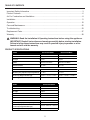 3
3
-
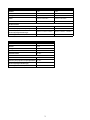 4
4
-
 5
5
-
 6
6
-
 7
7
-
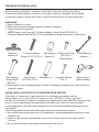 8
8
-
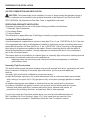 9
9
-
 10
10
-
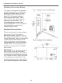 11
11
-
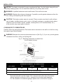 12
12
-
 13
13
-
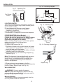 14
14
-
 15
15
-
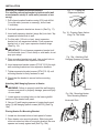 16
16
-
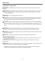 17
17
-
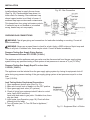 18
18
-
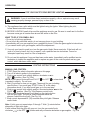 19
19
-
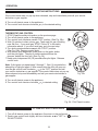 20
20
-
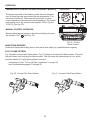 21
21
-
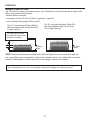 22
22
-
 23
23
-
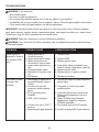 24
24
-
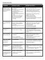 25
25
-
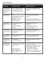 26
26
-
 27
27
-
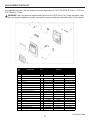 28
28
-
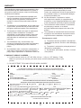 29
29
-
 30
30
-
 31
31
-
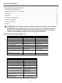 32
32
-
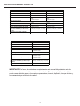 33
33
-
 34
34
-
 35
35
-
 36
36
-
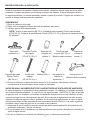 37
37
-
 38
38
-
 39
39
-
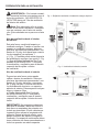 40
40
-
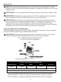 41
41
-
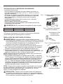 42
42
-
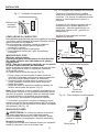 43
43
-
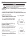 44
44
-
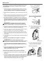 45
45
-
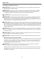 46
46
-
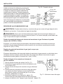 47
47
-
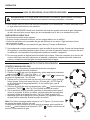 48
48
-
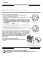 49
49
-
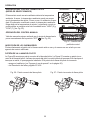 50
50
-
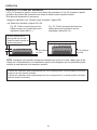 51
51
-
 52
52
-
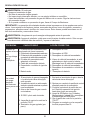 53
53
-
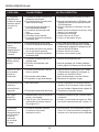 54
54
-
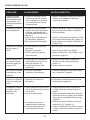 55
55
-
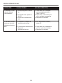 56
56
-
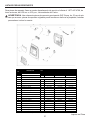 57
57
-
 58
58
-
 59
59
-
 60
60


Dyna-Glo BF20NMDG Guía de instalación
- Categoría
- Calentadores espaciales
- Tipo
- Guía de instalación
- Este manual también es adecuado para
En otros idiomas
- English: Dyna-Glo BF20NMDG Installation guide
Documentos relacionados
-
Dyna-Glo BF30NMDG-4 Manual de usuario
-
-
-
-
Dyna-Glo IR12PMDG-1 Manual de usuario
-
-
-
-
