
DE 18405
DE 21405
DE 24405
DE 27405
DE 40518
DE 40521
DE 40524
Montageanweisung
➔
2
Installation Instructions
➔
4
Manuel de montage
➔
6
Gebruiksaanwijzing
➔
8
Instrukcja monta˝u
➔
10
Инструкция по монтажу
➔
12
Instrucciones de instalación
➔
14
Manual de instalação
➔
16
➔
18
DE
GB
FR
NL
PL
RU
ES
PT
HK

2
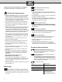
Montieren Sie den Durchlauferhitzer, wie im Bildteil
beschrieben. Beachten Sie die Hinweise im Text.
Sicherheitshinweise
■
Der Durchlauferhitzer darf nur von einem Fachmann
angeschlossen und in Betrieb genommen werden.
■
Die gesetzlichen Vorschriften des jeweiligen Landes, des
örtlichen Elektrizitäts-Versorgungsunternehmens und des
Wasserwerkes müssen eingehalten werden.
■
Der Durchlauferhitzer ist ein Gerät der Schutzklasse
I
und
muss
an den Schutzleiter angeschlossen werden.
■
Das Gerät muss dauerhaft an festverlegte Leitungen
angeschlossen werden.
■
Nur für Österreich: Bei Verwendung der Schutzmaßnahme
„Fehlerstrom-Schutzschaltung“ (sowohl bei bereits in
Ihrer Installation vorhandenem Fehlerstrom-Schutz-
schalter als auch bei Neuinstallation Ihrer Anlage) darf in
Verbindung mit diesem Gerät nur ein pulsstromsensitiver
Fehlerstrom-Schutzschalter vorgeschaltet werden.
■
Zur Erfüllung der einschlägigen Sicherheitsvorschriften
muss installationsseitig eine allpolige Trennvorrichtung
vorhanden sein. Die Kontaktöffnung muss mindestens
3 mm betragen.
■
Der Durchlauferhitzer ist nur für den geschlossenen
(druckfesten) Betrieb geeignet.
■
Armaturen müssen für den Betrieb mit geschlossenen
(druckfesten) Durchlauferhitzern zugelassen sein.
■
Den Durchlauferhitzer nur an eine Kaltwasserleitung
anschließen.
■
Der Durchlauferhitzer ist für den Anschluss an DVGW-
geprüfte Kunststoffrohre geeignet.
■
Den Durchlauferhitzer nur in einem frostfreien Raum
installieren.
■
Das elektrische Anschlusskabel vor der Montage
spannungslos machen und die Wasserzuleitung
absperren!
■
Den Elektroanschluss erst nach dem
Wasseranschluss durchführen.
■
In der Rückwand nur die Öffnungen herstellen, die
für die Montage benötigt werden. Bei erneuter Montage
müssen die unbenutzten Öffnungen wasserdicht ver-
schlossen werden.
■
Spannungsführende Teile dürfen nach der Montage nicht
mehr berührbar sein.
Montage
Auspacken/Haube abnehmen
■
Gerät auspacken und auf Transportschäden kontrollieren.
■
Verpackung und gegebenenfalls Altgerät umweltgerecht
entsorgen.
Montagevorbereitung
Wandmontage
■
Der Durchlauferhitzer muss fest an der Wand montiert
werden. Befestigen Sie ihn gegebenenfalls an den unteren
Stellschrauben.
■
Der Wandabstand ist variabel. So können Unebenheiten
der Wand ausgeglichen werden.
■
Die Tülle muss das Anschlusskabel eng umschließen.
Wird sie bei der Montage beschädigt, müssen die Löcher
wasserdicht verschlossen werden.
Wasseranschluss
■
Der Durchlauferhitzer muss entlüftet werden. Dazu
Warmwasserhahn ganz öffnen und das Gerät 1 Minute
durchspülen.
Elektroanschluss
■
Die Netzanschlussklemme kann oben oder unten montiert
werden. Die Ummantelung des Anschlusskabels muss
mindestens 40 mm in das Gerät hineinragen.
Inbetriebnahme
■
Entfernen Sie bei niedrigem Wasserleitungsdruck den
Durchflussbegrenzer (siehe Zusatzinformation A).
■
Erklären Sie dem Benutzer die Bedienung des
Durchlauferhitzers.
■
Trennen Sie die benötigte Sprachversion aus der
Gebrauchsanweisung. Sie kann in der aufklappbaren
Bedienblende des Durchlauferhitzers aufbewahrt werden.
Zusatzinformationen
Erreicht der Durchlauferhitzer aufgrund von zu
geringem Wasserleitungsdruck in Ihrer Hausinstalla-
tion keinen genügenden Durchfluss, entfernen Sie
den Durchflussbegrenzer.
Vorrangschaltung für die Kombination mit Elektro-
Speicherheizgeräten:
Für den Betrieb mit Vorrangschaltung ist ein speziel-
les Lastabwurfrelais BZ 45L20 (Sonderzubehör)
erforderlich. Andere, bereits vorhandene Lastabwurf-
relais, ausgenommen elektronische Lastabwurfrelais,
können Fehlfunktionen aufweisen.
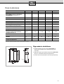
Statusanzeige im Gerät
I.
LED Gerätestatus
Aus Aus
Ein Bereitschaft
Langsames Blinken (1/s) Gerät heizt
Schnelles Blinken (4/s) Eingestellte Temperatur
wird nicht erreicht
(Wasserdurchfluss für die
Anschlussleistung zu hoch)
II.
III.
IV.
V.
VI.
A
B
C
DE

3
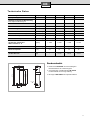
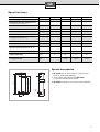
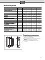
Technische Daten
* Hierzu kommt noch der Druckabfall an der Mischbatterie
Sonderzubehör
■
Rohrbausatz
BZ 45U20
: Zur Verwendung des
Durchlauferhitzers als Untertischgerät.
■
Vorrangschalter (Lastabwurfrelais)
BZ 45L20
:
Für den Betrieb mit Vorrangschaltung.
■
Montageset
BZ 45K22:
Für Aufputzinstallation.
Nennleistung
[kW] 18 21 24 27
Nennspannung
380 – 415 V
380 – 415 V 380 – 415 V 400 V3~
Warmwassermenge bei Nennleistung
bei Temperaturerhöhung von
12 °C auf 38 °C [l/min] 9,9 11,6 13,2 13,9
12 °C auf 60 °C [l/min] 5,4 6,3 7,2 7,6
Einschaltmenge
[l/min]
2,6 2,6 2,6 2,6
Einschaltfließdruck
* [MPa (bar)] 0,025 (0,25) 0,025 (0,25) 0,025 (0,25) 0,025 (0,25)
Fließdruck
(bei Nennleistung und 60 °C) *
mit Durchflussbegrenzer [MPa (bar)] 0,028 (0,28) 0,035 (0,35) 0,048 (0,48) 0,064 (0,64)
ohne Durchflussbegrenzer [MPa (bar)] 0,013 (0,13) 0,020 (0,20) 0,026 (0,26) 0,035 (0,35)
Einsatzbereich in Wässern
Spezifischer elektrischer
Widerstand bei 15 °C
[
Ω
cm]
≥
1300
≥
1300
≥
1300
≥
1300
Nenndruck
[MPa (bar)]
1 (10) 1 (10) 1 (10) 1 (10)
Maximal zulässige
Zulauf-Temperatur
[°C] 35 35 35 35
Maximale Netzimpedanz
am Anschlussort
[
Ω
]
–
≤ 0,44
≤ 0,36 ≤ 0,33
G
1
2
A
472
122
135
231
20
100
332
42
388
DE

4
Assemble the continuous-flow heater as shown in the
illustrations. Observe the information in the text.
Safety information
■ The continuous-flow heater must only be connected
and started up by an authorized technician.
■ The statutory regulations of the respective country, as well
as those of the local electricity and water suppliers must
be adhered to.
■ The continuous-flow heater is an appliance of protection
class I and must be connected to the protective earth
conductor.
■ The unit must be durably connected to permanently
installed lines.
■ In order to meet the current safety requirements, an
all-pole disconnecting device must be present on the
installation side. The contact gap must be at least 3 mm.
■ The continuous-flow heater is suitable for enclosed
(pressurized) operation only.
■ The tap fittings must be permitted for operation with
enclosed (pressurized) continuous-flow heaters.
■ The continuous-flow heater must only be connected to
a cold-water pipe.
■ The continuous-flow heater is suitable for connection to
DVGW-tested plastic pipes.
■ The continuous-flow heater must only be installed in
a frost-free room.
■ Prior to installation, the electric connecting cord
must be disconnected from the mains voltage and
the water supply cut off!
■ Only connect the electric supply after the water
supply.
■ When making holes in the rear wall, only make the
number of holes required for installation. If the appliance
is reinstalled, any holes that are not used must be made
watertight.
■ Live components must not be touched subsequent to
installation.
Assembly
Unpacking/removing the
housing cover
■ Unpack the appliance and check for transportation
damage.
■ Dispose of the packaging and, where applicable, the old
appliance, in an environmentally conscious manner.
Preparation for assembly
Wall-mounted assembly
■ The continuous-flow heater must be fitted securely to the
wall. If required, secure the appliance using the lower
adjusting screws.
■ The distance from the wall is variable. This allows you to
compensate for any unevenness in the wall surface.
■ The sleeve must fit tightly round the connection cable. If
the sleeve is damaged during installation, the holes must
be sealed water-tight.
Water supply
■ The flow-through heater must be vented. Open the
warm water tap completely and allow to flow through
for one minute.
Electric supply
■ The mains connection terminal can either be mounted
above or below. At least 40 mm of the connecting cord’s
insulating jacket must be clamped unside the appliance.
Startup
■ For low water line pressure, remove the flow limiter (see
Supplementary Information A).
■ Instruct the user with regard to the operation of the
continuous-flow heater.
■ Separate the required language version from the rest of
the operating instructions. This can be kept in the swing-
out control panel of the continuous-flow heater.
Additional information
If the flow-through heater does not achieve adequate
flow as a result of water line pressure that is too low
in your house installation, remove the flow limiter.
Priority circuit for the combination with electro-
storage heating units:
For operation with the priority circuit, a special load
reducing relay BZ 45L20 (special accessory) is
required. Other already existing load reducing relays
with the exception of electronic load reducing relays
could cause malfunctions.
Status Indicator in the Heater
I.
LED Heater Status
Off Off
On Ready
Slow blinking (1/s) Heating
Fast blinking (4/s)
The set temperatures are
not reached (the water flow
rate is too high for the
connection rating)
II.
III.
IV.
V.
VI.
A
B
C
GB

5
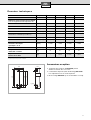
Specifications
* Plus any pressure loss at the tap mixer
Special accessories
■ BZ 45U20 Pipe set: When using the continuous-flow
heater as a built-under appliance.
■ Priority switch (load reducing relay) BZ 45L20:
For operation with the priority circuit.
■ BZ 45K22 Mounting set: For surface-mount installation.
Rated power [kW] 18 21 24 27
Rated voltage 380 – 415 V 380 – 415 V 380 – 415 V 400 V3~
Warm Water Quantity at Rated Power
for temperature increases of:
12 °C to 38 °C [l/min] 9.9 11.6 13.2 13.9
12 °C to 60 °C [l/min] 5.4 6.3 7.2 7.6
Switch-on quantity [l/min] 2.6 2.6 2.6 2.6
Switch-on flow pressure* [MPa (bar)] 0.025 (0.25) 0.025 (0.25) 0.025 (0.25) 0.025 (0.25)
Flow pressure
(at rated power and 60 °C)*
With flow limiter [MPa (bar)] 0.028 (0.28) 0.035 (0.35) 0.048 (0.48) 0.064 (0.64)
Without flow limiter [MPa (bar)] 0.013 (0,13) 0.020 (0,20) 0.026 (0,26) 0.035 (0,35)
Operative range in waters of
specific electric resistance at 15 °C
[Ωcm] ≥ 1300 ≥ 1300 ≥ 1300 ≥ 1300
Rated pressure [MPa (bar)] 1 (10) 1 (10) 1 (10) 1 (10)
Maximum permissible
supply temperature
[°C] 35 35 35 35
Maximum mains impedance
at connection site
[Ω] – ≤ 0,44 ≤ 0,36 ≤ 0,33
G
1
2
A
472
122
135
231
20
100
332
42
388
GB

6
Montez le chauffe-eau instantané en suivant les
indications portées sur les figures. Respectez les
consignes du texte.
Consignes de sécurité
■ Seul un installateur agréé est autorisé à raccorder et
à mettre en marche le chauffe-eau instantané.
■ Respectez les prescriptions légales en vigueur dans
votre pays ainsi que celles édictées par les compagnies
locales/nationales distributrices d’électricité et d’eau et
applicables dans votre localité.
■ Le chauffe-eau instantané est un appareil qui répond à la
classe de protection I. Il doit être raccordé au fil de terre.
■ L’appareil doit être raccordé de manière durable et non
provisoire à une tuyauterie fixe.
■ Afin de respecter les prescriptions de sécurité
applicables, l’installation doit comporter un dispositif de
coupure tous pôles. L’espace coupe-circuit entre les
contacts doit s’élever à 3 mm minimum.
■ Le chauffe-eau est conçu uniquement pour fonctionner
en circuit fermé (résistant à la pression).
■ La robinetterie doit pouvoir s’utiliser avec des chauffe-
eau fermés (résistant à la pression).
■ Raccordez le chauffe-eau uniquement à une conduite
d’eau froide.
■ Le chauffe-eau peut s’utiliser avec de la tuyauterie en
matière plastique approuvée DVGW.
■ Installez le chauffe-eau uniquement dans un local non
exposé au gel.
■ Avant le montage, mettez le câble d’alimentation
électrique hors tension et coupez l’arrivée d’eau.
■ Procédez d’abord au raccordement de l’eau, puis au
raccordement électrique.
■ Pratiquez dans la paroi arrière uniquement les
ouvertures nécessaires au montage. Si vous refaites le
montage, bouchez les ouvertures inutilisées afin de les
rendre étanches.
■ Une fois le montage terminé, les pièces
électroconductrices doivent être impossibles à toucher.
Montage
Déballage/Enlèvement du
capot
■ Déballez l’appareil et vérifiez s’il n’a pas subi de dégâts
pendant le transport.
■ Eliminez l’emballage et, le cas échéant, l’ancien appareil
en respectant l’environnement.
Préparation du montage
Montage mural
■ Le chauffe-eau instantané doit être solidement monté
contre le mur. Le cas échéant, fixez-le au moyen des vis
de réglage inférieures.
■ L’écart par rapport au mur est variable. Vous pouvez
ainsi compenser les inégalités du mur.
■ La gaine doit bien enserrer le cordon d’alimentation.
Si elle a été endommagée pendant le montage, bouchez
les trous pour les rendre étanches à l’eau.
Raccordement de l’eau
■ Le chauffe-eau doit être purgé. Pour ce faire, ouvrir
complètement le robinet d’eau chaude et laisser l’eau
s’écouler pendant une minute.
Branchement électrique
■ La borne de branchement au secteur peut être montée en
haut ou en bas. La gaine du câble d’alimentation doit
pénétrer au moins de 40 mm dans l’appareil.
Mise en service
■ Retirer le limiteur de débit si la pression de la conduite
d’arrivée d’eau est faible (cf. la section « Information com-
plémentaire et la fig. A »).
■ Expliquez à l’utilisateur le fonctionnement du chauffe-eau
instantané.
■ Sélectionnez dans la notice d’utilisation la version dans la
langue appropriée puis détachez-la. Vous pouvez la
ranger dans le bandeau de commande dépliant du
chauffe-eau instantané.
Informations supplémentaires
Si la pression de la conduite d’arrivée de l’eau de
votre installation est trop faible, le chauffe-eau peut
fournir un débit insuffisant. Pour augmenter le débit,
retirer alors le limiteur de débit.
Circuit de priorité pour l’association avec un radiateur
électrique à accumulation:
Pour travailler avec un circuit de priorité, il convient
d’installer un relais de délestage brusque spécial
BZ 45L20 (accessoire non fourni). Tout autre modèle
de relais de délestage brusque (à l’exception des
modèles électroniques) est susceptible de
dysfonctionner.
Signification de la diode électroluminescente (DEL)
I.
DEL Appareil
éteinte arrêté
allumée prêt à fonctionner
clignotement lent (1/s) l’appareil chauffe
clignotement rapide
(4/s)
La température programmée
n’est pas atteinte (le débit d’eau
est trop élevé pour la puissance
électrique disponible)
II.
III.
IV.
V.
VI.
A
B
C
FR

7
Données techniques
* Lui ajouter la perte de pression au mitigeur
Accessoires en option
■ Tuyauterie de montage en kit BZ 45U20: permet
d’utiliser le chauffe-eau sous l’évier.
■ Commutateur de priorité (relais de décharge) BZ 45L20 :
Pour exploitation avec un circuit de priorité.
■ Kit de montage BZ 45K22 : pour une installation sur crépi.
Puissance nominale [kW] 18 21 24 27
Tension nominale 380 – 415 V 380 – 415V 380 – 415 V 400 V3~
Débit d’eau fourni à la puissance nominale
pour une augmentation de température de
12 °C à 38 °C [l/min] 9,9 11,6 13,2 13,9
12 °C à 60 °C [l/min] 5,4 6,3 7,2 7,6
Débit de déclenchement [l/min] 2,6 2,6 2,6 2,6
Pression de déclenchement * [MPa (bar)] 0,025 (0,25) 0,025 (0,25) 0,025 (0,25) 0,025 (0,25)
Pression d’écoulement
(à puissance nominale et pour 60 °C)*
Avec limiteur de débit [MPa (bar)] 0,028 (0,28) 0,035 (0,35) 0,048 (0,48) 0,064 (0,64)
Sans limiteur de débit [MPa (bar)] 0,013 (0,13) 0,020 (0,20) 0,026 (0,26) 0,035 (0,35)
Rayon d’action dans l’eau
Résistance électrique
spécifique à 15 °C
[Ωcm] ≥ 1300 ≥ 1300 ≥ 1300 ≥ 1300
Pression nominale [MPa (bar)] 1 (10) 1 (10) 1 (10) 1 (10)
Température maximale
admissible à l’entrée
[°C] 35 35 35 35
Impédance maximale du
réseau sur les lieux
[Ω] – ≤ 0,44 ≤ 0,36 ≤ 0,33
G
1
2
A
472
122
135
231
20
100
332
42
388
FR

8
Monteer het doorstroom heetwaterapparaat volgens de
afbeeldingen. Volg de instructies in de tekst op.
Veiligheidsvoorschriften
■ Het doorstroom heetwaterapparaat mag uitsluitend
door een installateur aangesloten en in gebruik
worden genomen.
■ De wettelijke voorschriften van het betreffende land, van
het plaatselijke energiebedrijf en van het
waterleidingbedrijf opvolgen.
■ Het doorstroom heetwaterapparaat is een apparaat van
beschermklasse I en moet worden aangesloten op een
aardleiding.
■ Het toestel moet duurzaam op vast geïnstalleerde
leidingen worden aangesloten.
■ Om te voldoen aan de geldende veiligheidsvoorschriften
moet de installatie zijn voorzien van een stroomonder-
breker voor alle polen. De contactopening moet minimaal
3 mm bedragen.
■ Het apparaat is uitsluitend geschikt voor gesloten
(drukvast) gebruik.
■ Armaturen moeten goedgekeurd zijn voor gebruik met
gesloten (drukvaste) doorstroom heetwaterapparaten.
■ Het doorstroom heetwaterapparaat uitsluitend aansluiten
op een koudwaterleiding.
■ Het doorstroom heetwaterapparaat is geschikt voor
aansluiting op goedgekeurde kunststof buizen.
■ Het doorstroom heetwaterapparaat uitsluitend installeren
in een vorstvrije ruimte.
■ De elektrische aansluitkabel voor de montage
spanningsloos maken en de wateraanvoer afsluiten!
■ De elektrische aansluiting pas uitvoeren nadat het
water is aangesloten.
■ Maak in de achterzijde uitsluitend gaten die nodig zijn
voor de montage. Als het apparaat opnieuw wordt
gemonteerd, moeten de ongebruikte gaten waterdicht
worden afgesloten.
■ Onder spanning staande onderdelen mogen na de
montage niet meer aangeraakt kunnen worden.
Montage
Uitpakken/kap verwijderen
■ Het apparaat uitpakken en controleren op transport-
schade.
■ De verpakking en eventueel het oude apparaat op
milieuvriendelijke wijze afvoeren.
Montagevoorbereiding
Montage op de muur
■ Het doorstroom heetwaterapparaat moet vast op de
muur worden gemonteerd. Bevestig het apparaat
eventueel aan de onderste stelschroeven.
■ De afstand tot de muur is variabel. Zo kunnen
oneffenheden van de muur worden gecompenseerd.
■ De tule moet de aansluitkabel nauw omsluiten. Als de
tule beschadigd raakt tijdens de montage, moeten de
gaten waterdicht worden afgesloten.
Wateraansluiting
■ Het doorstroomtoestel moet worden ontlucht.
Open daarvoor de warmwaterkraan helemaal en spoel
het toestel gedurende één minuut door.
Elektro-aansluiting
■ De netaansluitklem kan boven of beneden gemonteerd
worden. De mantel van de aansluitkabel moet minstens
40 mm in het toestel naar binnen steken.
Ingebruikneming
■ Verwijder bij een lage waterleidingdruk de doorstroom-
begrenzer (zie aanvullende informatie A).
■ Leg de gebruiker uit hoe het doorstroom
heetwaterapparaat wordt bediend.
■ Haal de gewenste taalversie uit de gebruiksaanwijzing.
U kunt deze bewaren in het uitklapbare bedieningspaneel
van het doorstroom heetwaterapparaat.
Aanvullende informatie
Wanneer het doorstroomtoestel wegens te geringe
waterdruk in uw huisinstallatie geen voldoende
doorstroming krijgt, moet u de doorstroombegrenzer
verwijderen.
Voorrangschakeling voor de combinatie met elektri-
sche reservoirverwarmingsapparaten:
Voor het gebruik met voorrangschakeling is een
speciaal lastafwerprelais BZ 45L20 (speciaal
toebehoren) vereist. Andere, reeds aanwezige
lastafwerprelais, met uitzondering van elektronische
lastafwerprelais, kunnen gebrekkig functioneren.
Statusaanduiding in het apparaat
I.
LED Apparaatstatus
Uit Uit
Aan Standby
Langzaam knipperen (1/s) Apparaat verwarmt
Snel knipperen (4/s)
Ingestelde temperatuur
wordt niet bereikt
(waterdoorvoer voor de
aansluitcapaciteit te groot)
II.
III.
IV.
V.
VI.
A
B
C
NL

9
Technische gegevens
* Dit is exclusief de drukvermindering bij de mengkraan
Speciaal toebehoren
■ Buizenmontageset BZ 45U20: voor gebruik van het
doorstroom heetwaterapparaat als keukenboiler.
■ Voorrangschakelaar (lastafwerprelais) BZ 45L20:
Voor het gebruik met voorrangschakeling.
■ Montageset BZ 45K22: Voor opbouwmontage.
Nominaal vermogen [kW] 18 21 24 27
Nominale spanning 380 – 415 V 380 – 415 V 380 – 415 V 400 V3~
Warmwaterhoeveelheid bij nominale
capaciteit
bij temperatuurverhoging van
12 °C naar 38 °C [l/min] 9,9 11,6 13,2 13,9
12 °C naar 60 °C [l/min] 5,4 6,3 7,2 7,6
Inschakelhoeveelheid [l/min] 2,6 2,6 2,6 2,6
Inschakelstroomduk* [MPa (bar)] 0,025 (0,25) 0,025 (0,25) 0,025 (0,25) 0,025 (0,25)
Stroomdruk
(bij nominale capaciteit en 60 °C) *
met doorstroombegrenzer [MPa (bar)] 0,028 (0,28) 0,035 (0,35) 0,048 (0,48) 0,064 (0,64)
zonder doorstroombegrenzer [MPa (bar)] 0,013 (0,13) 0,020 (0,20) 0,026 (0,26) 0,035 (0,35)
Toepassingsbereik bij water
met een specifieke elektrische
weerstand op 15 °C
[Ωcm] ≥ 1300 ≥ 1300 ≥ 1300 ≥ 1300
Nominale druk [MPa (bar)] 1 (10) 1 (10) 1 (10) 1 (10)
Maximaal toegestane
toevoertemperatuur
[°C] 35 35 35 35
Maximale netimpedantie
op de aansluitlocatie
[Ω] – ≤ 0,44 ≤ 0,36 ≤ 0,33
G
1
2
A
472
122
135
231
20
100
332
42
388
NL

10
Podgrzewacz przep∏ywowy zamontowaç tak, jak to
opisano w cz´Êci z rysunkami. Przestrzegaç wskazówek
podanych w tekÊcie.
Wskazówki bezpieczeƒstwa
■ Przy∏àczenia i pierwszego uruchomienia
podgrzewacza przep∏ywowego mo˝e dokonaç tylko
uprawniony specjalista.
■ Przestrzegaç obowiàzujàcych przepisów krajowych,
przepisów miejscowych zak∏adów energetycznych i
wodociàgowych.
■ Podgrzewacz przep∏ywowy jest urzàdzeniem klasy
bezpieczeƒstwa I i musi byç pod∏àczone do przewodu
uziemiajàcego.
■ Urzàdzenie musi byç na sta∏e zamontowane do sieci
wodno-kanalizacyjnej.
■ W celu spe∏nienia warunków obowiàzujàcych przepisów
bezpieczeƒstwa nale˝y wyposa˝yç instalacj´ elektrycznà
w wy∏àcznik wszystkich faz. Rozwarcie styków wy∏àcznika
musi wynosiç co najmniej 3 mm.
■ Podgrzewacz przep∏ywowy przeznaczony jest tylko do
pracy zamkni´tej (sta∏e ciÊnienie).
■ Zastosowaç armatur´, która dopuszczona jest do pracy
zamkni´tej (sta∏e ciÊnienie).
■ Podgrzewacz przep∏ywowy pod∏àczaç tylko do przewodu
zimnej wody.
■ Podgrzewacz przep∏ywowy nadaje si´ do przy∏àczenia do
przewodów rurowych z tworzywa sztucznego, które
posiadajà certyfikat DVGW.
■ Podgrzewacz przep∏ywowy musi byç zainstalowany w
pomieszczeniu chroniàcym przed mrozem.
■ Przed przystàpieniem do monta˝u wy∏àczyç przewód
elektryczny spod napi´cia i zamknàç wodny zawór
odcinajàcy!
■ Przy∏àcza wodne wykonaç przed pod∏àczeniem
urzàdzenia do sieci elektrycznej.
■ W tylnej Êciance wy∏amaç tylko te otwory, które konieczne
sà do monta˝u. W przypadku ponownego monta˝u nale˝y
zb´dne otwory zaÊlepiç wodoszczelnie.
■ Cz´Êci przewodzàce pràd nie mogà byç dost´pne po
monta˝u.
Monta˝
Rozpakowanie/zdejmowanie
pokrywy
■ Urzàdzenie rozpakowaç i sprawdziç, czy nie posiada
uszkodzeƒ powsta∏ych w czasie transportu.
■ Opakowanie i stare urzàdzenie usunàç w sposób zgodny
z przepisami o ochronie Êrodowiska.
Przygotowanie do monta˝u
Monta˝ na Êcianie
■ Podgrzewacz przep∏ywowy musi byç zamontowany na
sta∏e na Êcianie. W takim przypadku zamocowaç go na
dolnych Êrubach mocujàcych.
■ Odleg∏oÊç od Êciany jest ró˝na. W taki sposób mo˝na
wyrównaç nierównoÊci Êciany.
■ Tulejka ochronna musi ciasno obejmowaç przewód
elektryczny. W przypadku uszkodzenia tulejki przy
monta˝u, nale˝y zaÊlepiç otwory wodoszczelnie.
Przy∏àcze wodne
■ Przep∏ywowy ogrzewacz wody musi byç odpowietrzony.
Kran ciep∏ej wody ca∏kowicie odkr´ciç i przez 1 minut´
urzàdzenie p∏ukaç.
Przy∏àcze elektryczne
■ Przy∏àczeniowy zacisk sieciowy mo˝e byç zamontowany
na górze lub na dole. Izolacja zewn´trzna (p∏aszcz) kabla
przy∏àczeniowego musi si´gaç przynajmniej na 40 mm
wg∏àb urzàdzenia.
Uruchomienie
■ Przy niskim ciÊnieniu wody usunàç ogranicznik przep∏ywu
(patrz tak˝e informacja dodatkowa A).
■ Prosz´ wyjaÊniç u˝ytkownikowi obs∏ug´ podgrzewacza
przep∏ywowego.
■ Z instrukcji u˝ytkowania wybraç w∏aÊciwà wersj´
j´zykowà. Mo˝na jà przechowywaç w odchylanym pulpicie
obs∏ugi podgrzewacza.
Informacje dodatkowe
JeÊli na skutek zbyt niskiego ciÊnienia wody w
instalacji domowej ogrzewacz nie osiàgnie
odpowiedniego przep∏ywu, usunàç ogranicznik
przep∏ywu.
Za∏àczanie wst´pne kombinacji elektrycznych piecy
akumulacyjnych:
do pracy z za∏àczaniem wst´pnym niezb´dny jest
specjalny przekaênik przecià˝eniowy BZ 45L20
(wyposa˝enie dodatkowe). Inne, aktualnie u˝ywane,
z wy∏àczeniem elektronicznych przekaêników
przecià˝eniowych, mogà pracowaç nieprawid∏owo.
Wskazania stanu urzàdzenia■
I.
Dioda LED Stan urzàdzenia
Wy∏àczone Wy∏àczone
W∏àczone Stan gotowoÊci
B∏yska powoli (1/s) Urzàdzenie grzeje
B∏yska szybko (4/s)
Nastawiona temperatura nie
zostanie osiàgni´ta
(zbyt du˝y przep∏yw wody dla
przepustowoÊci przy∏àcza)
II.
III.
IV.
V.
VI.
A
B
C
PL

11
Dane techniczne
* Tutaj nale˝y uwzgl´dniç dodatkowo spadek ciÊnienia na baterii mieszajàcej
Wyposa˝enie dodatkowe
■ Zestaw kszta∏tek i z∏àczek rurowych BZ 45U20: do
zamontowania podgrzewacza przep∏ywowego pod
umywalkà.
■ W∏àcznik wst´pny (przekaênik obcià˝eniowy) BZ 45L20:
do pracy z zabezpieczeniem przecià˝eniowym.
■ Zestaw monta˝owy BZ 45K22: dla instalacji natynkowej.
Moc znamionowa [kW] 18 21 24 27
Napi´cie znamionowe 380 – 415 V 380 – 415 V 380 – 415 V 400 V3~
IloÊç ciep∏ej wody przy wydajnoÊci
znamionowej,
przy podniesieniu temperatury z:
12 °C na 38 °C [l/min] 9,9 11,6 13,2 13,9
12 °C na 60 °C [l/min] 5,4 6,3 7,2 7,6
IloÊç za∏àczajàca [l/min] 2,6 2,6 2,6 2,6
CiÊnienie hydrauliczne za∏àczenia* [MPa (bary)] 0,025 (0,25) 0,025 (0,25) 0,025 (0,25) 0,025 (0,25)
CiÊnienie hydrauliczne
(przy wydajnoÊci nominalnej i 60°C) *
z ogranicznikiem przep∏ywu [MPa (bary)] 0,028 (0,28) 0,035 (0,35) 0,048 (0,48) 0,064 (0,64)
bez ogranicznika przep∏ywu [MPa (bary)] 0,013 (0,13) 0,020 (0,20) 0,026 (0,26) 0,035 (0,35)
Zakres stosowania dla wody o
opornoÊci elektrycznej w∏aÊciwej
w temperaturze 15 °C
[Ωcm] ≥ 1300 ≥ 1300 ≥ 1300 ≥ 1300
CiÊnienie znamionowe [MPa (bary)] 1 (10) 1 (10) 1 (10) 1 (10)
Maksymalna dopuszczalna temperatura
dop∏ywu
[°C] 35 35 35 35
Maksymalna impedancja sieciowa
w miejscu przy∏àczenia
[Ω] – ≤ 0,44 ≤ 0,36 ≤ 0,33
G
1
2
A
472
122
135
231
20
100
332
42
388
PL

12
VV
VV
yy
yy
pp
pp
oo
oo
ll
ll
nn
nn
ää
ää
jj
jj
tt
tt
ee
ee
mm
mm
oo
oo
nn
nn
tt
tt
aa
aa
øø
øø
pp
pp
rr
rr
oo
oo
tt
tt
oo
oo
hh
hh
nn
nn
oo
oo
gg
gg
oo
oo
nn
nn
aa
aa
gg
gg
rr
rr
ee
ee
vv
vv
aa
aa
tt
tt
ee
ee
ll
ll
ää
ää
tt
tt
aa
aa
kk
kk
,,
,,
kk
kk
aa
aa
kk
kk
pp
pp
oo
oo
kk
kk
aa
aa
zz
zz
aa
aa
nn
nn
oo
oo
nn
nn
aa
aa
rr
rr
ii
ii
ss
ss
uu
uu
nn
nn
kk
kk
aa
aa
xx
xx
..
..
PP
PP
rr
rr
ii
ii
qq
qq
tt
tt
oo
oo
mm
mm
rr
rr
uu
uu
kk
kk
oo
oo
vv
vv
oo
oo
dd
dd
ss
ss
tt
tt
vv
vv
uu
uu
jj
jj
tt
tt
ee
ee
ss
ss
ææ
ææ
uu
uu
kk
kk
aa
aa
zz
zz
aa
aa
nn
nn
ii
ii
ää
ää
mm
mm
ii
ii
,,
,,
pp
pp
rr
rr
ii
ii
vv
vv
ee
ee
dd
dd
ee
ee
nn
nn
nn
nn
yy
yy
mm
mm
ii
ii
vv
vv
tt
tt
ee
ee
kk
kk
ss
ss
tt
tt
ee
ee
ii
ii
nn
nn
ss
ss
tt
tt
rr
rr
uu
uu
kk
kk
cc
cc
ii
ii
ii
ii
..
..
UU
UU
kk
kk
aa
aa
zz
zz
aa
aa
nn
nn
ii
ii
ää
ää
pp
pp
oo
oo
tt
tt
ee
ee
xx
xx
nn
nn
ii
ii
kk
kk
ee
ee
bb
bb
ee
ee
zz
zz
oo
oo
pp
pp
aa
aa
ss
ss
nn
nn
oo
oo
ss
ss
tt
tt
ii
ii
■ PP
PP
oo
oo
dd
dd
kk
kk
ll
ll
üü
üü
hh
hh
ee
ee
nn
nn
ii
ii
ee
ee
ii
ii
vv
vv
vv
vv
oo
oo
dd
dd
nn
nn
aa
aa
gg
gg
rr
rr
ee
ee
vv
vv
aa
aa
tt
tt
ee
ee
ll
ll
ää
ää
vv
vv
qq
qq
kk
kk
ss
ss
pp
pp
ll
ll
uu
uu
aa
aa
tt
tt
aa
aa
cc
cc
ii
ii
üü
üü
dd
dd
oo
oo
ll
ll
øø
øø
nn
nn
yy
yy
vv
vv
yy
yy
pp
pp
oo
oo
ll
ll
nn
nn
ää
ää
tt
tt
ææ
ææ
ss
ss
ää
ää
tt
tt
oo
oo
ll
ll
ææ
ææ
kk
kk
oo
oo
ss
ss
ii
ii
ll
ll
aa
aa
mm
mm
ii
ii
kk
kk
vv
vv
aa
aa
ll
ll
ii
ii
ff
ff
ii
ii
cc
cc
ii
ii
rr
rr
oo
oo
vv
vv
aa
aa
nn
nn
nn
nn
yy
yy
xx
xx
ss
ss
pp
pp
ee
ee
cc
cc
ii
ii
aa
aa
ll
ll
ii
ii
ss
ss
tt
tt
oo
oo
vv
vv
..
..
■ Pri qtom v obäzatelænom porädke doløny vypolnätæsä
predpisaniä, ustanovlennye zakonom v Vaπej strane, i
ukazaniä mestnyx predpriätij po qlektro- i
vodosnabøeniü.
■ Protohnyj nagrevatelæ predstavläet soboj
nagrevatelænyj pribor s klassom zawity ÛÛ
ÛÛ
, kotoryj
dd
dd
oo
oo
ll
ll
øø
øø
ee
ee
nn
nn
bytæ nepremenno podklühen k zawitnomu
provodniku.
■ Qlektronagrevatel´ doløen byt´ osnovatel´no i
nadeΩno podklüçen k stacionarnoj qlektroprovodke.
■ Dlä vypolneniä ukazanij vsex sootvetstvuüwix
predpisanij po texnike bezopasnosti specialistom,
provodäwim podklühenie nagrevatelä, doløno bytæ
predusmotreno razßedinäüwee ustrojstvo. Zazor
meødu kontaktami ustrojstva v otkrytom sostoänii
doløen sostavlätæ minimum 3 mm.
■ Dannyj protohnyj nagrevatelæ rasshitan na
qkspluataciü s sozdaniem vnutrennego davleniä
(nagrevatelæ zakrytogo tipa).
■ Ispolæzuemaä armatura doløna bytæ prednaznahena
dlä qkspluatacii v kombinacii s protohnymi
nagrevatelämi zakrytogo tipa.
■ Protohnyj nagrevatelæ moøno podklühatæ tolæko
k vodoprovodu xolodnoj vody.
■ Dannyj nagrevatelæ moøno podklühatæ k
plastmassovym trubam, vyderøavπim DVGW-test.
■ Protohnyj nagrevatelæ moøno ustanavlivatæ tolæko v
otaplivaemyx pomeweniäx.
■ PP
PP
ee
ee
rr
rr
ee
ee
dd
dd
vv
vv
yy
yy
pp
pp
oo
oo
ll
ll
nn
nn
ee
ee
nn
nn
ii
ii
ee
ee
mm
mm
qq
qq
ll
ll
ee
ee
kk
kk
tt
tt
rr
rr
oo
oo
mm
mm
oo
oo
nn
nn
tt
tt
aa
aa
øø
øø
aa
aa
ss
ss
ee
ee
tt
tt
ee
ee
vv
vv
oo
oo
jj
jj
kk
kk
aa
aa
bb
bb
ee
ee
ll
ll
ææ
ææ
ss
ss
ll
ll
ee
ee
dd
dd
uu
uu
ee
ee
tt
tt
oo
oo
tt
tt
kk
kk
ll
ll
üü
üü
hh
hh
aa
aa
tt
tt
ææ
ææ
oo
oo
tt
tt
ss
ss
ee
ee
tt
tt
ii
ii
ii
ii
pp
pp
ee
ee
rr
rr
ee
ee
kk
kk
rr
rr
yy
yy
vv
vv
aa
aa
tt
tt
ææ
ææ
pp
pp
oo
oo
dd
dd
aa
aa
hh
hh
uu
uu
vv
vv
oo
oo
dd
dd
yy
yy
!!
!!
■
QQ
QQ
ll
ll
ee
ee
kk
kk
tt
tt
rr
rr
oo
oo
pp
pp
oo
oo
dd
dd
kk
kk
ll
ll
üü
üü
hh
hh
ee
ee
nn
nn
ii
ii
ee
ee
dd
dd
oo
oo
ll
ll
øø
øø
nn
nn
oo
oo
vv
vv
yy
yy
pp
pp
oo
oo
ll
ll
nn
nn
ää
ää
tt
tt
ææ
ææ
ss
ss
ää
ää
pp
pp
oo
oo
ss
ss
ll
ll
ee
ee
pp
pp
oo
oo
dd
dd
kk
kk
ll
ll
üü
üü
hh
hh
ee
ee
nn
nn
ii
ii
ää
ää
vv
vv
oo
oo
dd
dd
yy
yy
..
..
■ V zadnej stenke nagrevatelä sleduet probivatæ liπæ te
otverstiä, kotorye neobxodimy dlä vypolneniä
montaøa. Pri povtornom montaøe nagrevatelä
nenuønye otverstiä doløny bytæ nepremenno
germetihno zadelany.
■ Montaø nagrevatelä doløen bytæ vypolnen takim
obrazom, htoby sluhajnoe prikosnovenie k
tokoveduwim detaläm nagrevatelä bylo polnostæü
isklüheno.
MM
MM
oo
oo
nn
nn
tt
tt
aa
aa
øø
øø
RR
RR
aa
aa
ss
ss
pp
pp
aa
aa
kk
kk
oo
oo
vv
vv
yy
yy
vv
vv
aa
aa
nn
nn
ii
ii
ee
ee
//
//
SS
SS
nn
nn
ää
ää
tt
tt
ii
ii
ee
ee
kk
kk
rr
rr
yy
yy
ππ
ππ
kk
kk
ii
ii
■ Raspakujte nagrevatelæ i ubeditesæ, hto vo vremä
transportirovki on ne byl povreøden.
■ Utilizaciü upakovki i otsluøivπego svoj srok starogo
nagrevatelä (esli takovoj imeetsä) provedite v
sootvetstvii s ukazaniämi predpisanij po zawite
okruøaüwej sredy.
PP
PP
oo
oo
dd
dd
gg
gg
oo
oo
tt
tt
oo
oo
vv
vv
kk
kk
aa
aa
kk
kk
mm
mm
oo
oo
nn
nn
tt
tt
aa
aa
øø
øø
uu
uu
NN
NN
aa
aa
ss
ss
tt
tt
ee
ee
nn
nn
nn
nn
yy
yy
jj
jj
mm
mm
oo
oo
nn
nn
tt
tt
aa
aa
øø
øø
■ Protohnyj nagrevatelæ doløen bytæ prohno
prikreplen k stene. Esli neobxodimo, to ego moøno
dopolnitelæno prikrepitæ vnizu ustanovohnymi
vintami.
■ Rasstoänie ot zadnej stenki nagrevatelä do steny
pomeweniä moøno regulirovatæ, hto daet vozmoønostæ
skompensirovatæ nerovnosti steny.
■ Nasadka doløna plotno oxvatyvatæ kabelæ.
Esli pri montaøe ona budet povreødena, to
obrazovavπiesä otverstiä sleduet germetihno
zadelatæ.
PP
PP
oo
oo
dd
dd
kk
kk
ll
ll
üü
üü
hh
hh
ee
ee
nn
nn
ii
ii
ee
ee
vv
vv
oo
oo
dd
dd
yy
yy
■ II
II
zz
zz
pp
pp
rr
rr
åå
åå
mm
mm
oo
oo
tt
tt
oo
oo
hh
hh
nn
nn
oo
oo
gg
gg
oo
oo
vv
vv
oo
oo
dd
dd
oo
oo
pp
pp
oo
oo
dd
dd
oo
oo
gg
gg
rr
rr
ee
ee
vv
vv
aa
aa
tt
tt
ee
ee
ll
ll
åå
åå
nn
nn
ee
ee
oo
oo
bb
bb
xx
xx
oo
oo
dd
dd
ii
ii
mm
mm
oo
oo
uu
uu
dd
dd
aa
aa
ll
ll
ii
ii
tt
tt
´´
´´
vv
vv
oo
oo
zz
zz
dd
dd
uu
uu
xx
xx
..
..
DD
DD
ll
ll
ää
ää
qq
qq
tt
tt
oo
oo
gg
gg
oo
oo
nn
nn
ee
ee
oo
oo
bb
bb
xx
xx
oo
oo
dd
dd
ii
ii
mm
mm
oo
oo
pp
pp
oo
oo
ll
ll
nn
nn
oo
oo
ss
ss
tt
tt
´´
´´
œœ
œœ
oo
oo
tt
tt
kk
kk
rr
rr
yy
yy
tt
tt
´´
´´
kk
kk
rr
rr
aa
aa
nn
nn
gg
gg
oo
oo
rr
rr
åå
åå
hh
hh
ee
ee
jj
jj
vv
vv
oo
oo
dd
dd
yy
yy
ii
ii
pp
pp
rr
rr
oo
oo
mm
mm
yy
yy
tt
tt
´´
´´
aa
aa
gg
gg
rr
rr
ee
ee
gg
gg
aa
aa
tt
tt
vv
vv
tt
tt
ee
ee
hh
hh
ee
ee
nn
nn
ii
ii
ee
ee
11
11
mm
mm
ii
ii
nn
nn
uu
uu
tt
tt
yy
yy
..
..
QQ
QQ
ll
ll
ee
ee
kk
kk
tt
tt
rr
rr
oo
oo
pp
pp
oo
oo
dd
dd
kk
kk
ll
ll
üü
üü
hh
hh
ee
ee
nn
nn
ii
ii
ee
ee
■ Клемма для подключения сетевого питания может
быть установлена сверху или снизу. Покрытие
соединительного кабеля должно входить, как
минимум, на 40 мм в устройство
.
VV
VV
vv
vv
oo
oo
dd
dd
vv
vv
qq
qq
kk
kk
ss
ss
pp
pp
ll
ll
uu
uu
aa
aa
tt
tt
aa
aa
cc
cc
ii
ii
üü
üü
■ Pri poniøennom davlenii v vodoprovode udalite
ograniçitel´ rasxoda (sm. punkt «Dopolnitel´nye
svedeniä A»).
■ Obßäsnite polæzovatelü, kak obrawatæsä
s nagrevatelem.
■ Otdelite instrukciü na russkom äzyke ot obwej
instrukcii. Ee moøno xranitæ pod otkidnoj kryπkoj
protohnogo nagrevatelä.
DD
DD
oo
oo
pp
pp
oo
oo
ll
ll
nn
nn
ii
ii
tt
tt
ee
ee
ll
ll
ææ
ææ
nn
nn
aa
aa
ää
ää
ii
ii
nn
nn
ff
ff
oo
oo
rr
rr
mm
mm
aa
aa
cc
cc
ii
ii
ää
ää
Esli napor vody v doma‚nem vodoprovode
nedostatoçen i poqtomu obßemnyj rasxod vody
çerez qlektronagrevatel´ sli‚kom nizok, udalite
ograniçitel´ rasxoda.
Izbiratelænaå kommutaciå dlå kombinacii s
priborami akkumulåtornogo qlektrootopleniå:
Dlå qkspluatacii s izbiratelænoj kommutaciej
trebuetså specialænoe rele sbrosa nagruzki
BZ 45L20 (specialænaå prinadleΩnostæ). Drugie,
uΩe imeœwieså rele sbrosa nagruzki, za
isklύeniem qlektronnyx rele sbrosa nagruzki,
mogut rabotatæ nepravilæno.
Indikaciå sostoåniä ustrojstva
■
I.
SS
SS
vv
vv
ee
ee
tt
tt
oo
oo
dd
dd
ii
ii
oo
oo
dd
dd
SS
SS
oo
oo
ss
ss
tt
tt
oo
oo
ää
ää
nn
nn
ii
ii
ee
ee
uu
uu
ss
ss
tt
tt
rr
rr
oo
oo
jj
jj
ss
ss
tt
tt
vv
vv
aa
aa
Ne gorit Vyklœheno
Gorit Gotovo k rabote
Migaet v medlennom
tempe (1/s)
V reΩime nagreva
Migaet v hastom
tempe (4/s)
Zadannaä temperatura ne
dostigaetsä (Rasxod vody dlä
dannoj mownosti sliπkom vysok)
II.
III.
IV.
V.
VI.
A
B
C
RU

13
TT
TT
ee
ee
xx
xx
nn
nn
ii
ii
hh
hh
ee
ee
ss
ss
kk
kk
ii
ii
ee
ee
dd
dd
aa
aa
nn
nn
nn
nn
yy
yy
ee
ee
* Süda dobavläetsä ewe padenie davleniä u smesitelä
SS
SS
pp
pp
ee
ee
cc
cc
ii
ii
aa
aa
ll
ll
ææ
ææ
nn
nn
yy
yy
ee
ee
pp
pp
rr
rr
ii
ii
nn
nn
aa
aa
dd
dd
ll
ll
ee
ee
øø
øø
nn
nn
oo
oo
ss
ss
tt
tt
ii
ii
■ Komplekt trub BZ 45U20: dlä ustanovki protohnogo
nagrevatelä pod umyvalænikom.
■ Izbiratelænyj vyklœçatelæ (rele sbrosa nagruzki)
BZ 45L20:
Dlå raboty s izbiratelænoj kommutaciej.
■ Набор для монтажа BZ 45K22: Для внешней
установки.
NN
NN
oo
oo
mm
mm
ii
ii
nn
nn
aa
aa
ll
ll
ææ
ææ
nn
nn
aa
aa
ää
ää
mm
mm
oo
oo
ww
ww
nn
nn
oo
oo
ss
ss
tt
tt
ææ
ææ
[kVt] 18 21 24 27
NN
NN
oo
oo
mm
mm
ii
ii
nn
nn
aa
aa
ll
ll
ææ
ææ
nn
nn
oo
oo
ee
ee
nn
nn
aa
aa
pp
pp
rr
rr
ää
ää
øø
øø
ee
ee
nn
nn
ii
ii
ee
ee
380 – 415 V 380 – 415 V 380 – 415 V 400 V3~
OO
OO
bb
bb
ßß
ßß
ee
ee
mm
mm
nn
nn
yy
yy
jj
jj
rr
rr
aa
aa
ss
ss
xx
xx
oo
oo
dd
dd
gg
gg
oo
oo
rr
rr
ää
ää
çç
çç
ee
ee
jj
jj
vv
vv
oo
oo
dd
dd
yy
yy
pp
pp
rr
rr
ii
ii
nn
nn
oo
oo
mm
mm
ii
ii
nn
nn
aa
aa
ll
ll
´´
´´
nn
nn
oo
oo
jj
jj
mm
mm
oo
oo
ww
ww
nn
nn
oo
oo
ss
ss
tt
tt
ii
ii
::
::
Pri nagreve ot 12 do 38°S [l/min] 9,9 11,6 13,2 13,9
Pri nagreve ot 12 do 60°S [l/min] 5,4 6,3 7,2 7,6
OO
OO
bb
bb
ßß
ßß
ee
ee
mm
mm
nn
nn
yy
yy
jj
jj
rr
rr
aa
aa
ss
ss
xx
xx
oo
oo
dd
dd
,,
,,
nn
nn
ee
ee
oo
oo
bb
bb
xx
xx
oo
oo
dd
dd
ii
ii
mm
mm
yy
yy
jj
jj
dd
dd
ll
ll
ää
ää
vv
vv
kk
kk
ll
ll
üü
üü
çç
çç
ee
ee
nn
nn
ii
ii
ää
ää
[l/min] 2,6 2,6 2,6 2,6
DD
DD
aa
aa
vv
vv
ll
ll
ee
ee
nn
nn
ii
ii
ee
ee
ii
ii
ss
ss
tt
tt
ee
ee
çç
çç
ee
ee
nn
nn
ii
ii
ää
ää
((
((
MM
MM
PP
PP
aa
aa
))
))
pp
pp
rr
rr
ii
ii
vv
vv
kk
kk
ll
ll
üü
üü
çç
çç
ee
ee
nn
nn
ii
ii
ii
ii
*
[МПа (бар)] 0,025 (0,25) 0,025 (0,25) 0,025 (0,25) 0,025 (0,25)
DD
DD
aa
aa
vv
vv
ll
ll
ee
ee
nn
nn
ii
ii
ee
ee
ii
ii
ss
ss
tt
tt
ee
ee
çç
çç
ee
ee
nn
nn
ii
ii
ää
ää
((
((
MM
MM
PP
PP
aa
aa
))
))
pp
pp
rr
rr
ii
ii
nn
nn
oo
oo
mm
mm
ii
ii
nn
nn
aa
aa
ll
ll
´´
´´
nn
nn
oo
oo
jj
jj
mm
mm
oo
oo
ww
ww
nn
nn
oo
oo
ss
ss
tt
tt
ii
ii
ii
ii
66
66
00
00
°°
°°
SS
SS
::
::
**
**
S ograniçitelem rasxoda [МПа (бар)] 0,028 (0,28) 0,035 (0,35) 0,048 (0,48) 0,064 (0,64)
Bez ograniçitelä rasxoda [МПа (бар)] 0,013 (0,13) 0,020 (0,20) 0,026 (0,26) 0,035 (0,35)
OO
OO
bb
bb
ll
ll
aa
aa
ss
ss
tt
tt
ææ
ææ
pp
pp
rr
rr
ii
ii
mm
mm
ee
ee
nn
nn
ee
ee
nn
nn
ii
ii
ää
ää
vv
vv
ss
ss
ll
ll
uu
uu
hh
hh
aa
aa
ee
ee
ii
ii
ss
ss
pp
pp
oo
oo
ll
ll
ææ
ææ
zz
zz
oo
oo
vv
vv
aa
aa
nn
nn
ii
ii
ää
ää
vv
vv
oo
oo
dd
dd
yy
yy
,,
,,
ii
ii
mm
mm
ee
ee
üü
üü
ww
ww
ee
ee
jj
jj
pp
pp
rr
rr
ii
ii
11
11
55
55
°°
°°
SS
SS
uu
uu
dd
dd
ee
ee
ll
ll
ææ
ææ
nn
nn
oo
oo
ee
ee
qq
qq
ll
ll
ee
ee
kk
kk
tt
tt
rr
rr
ii
ii
hh
hh
ee
ee
ss
ss
kk
kk
oo
oo
ee
ee
ss
ss
oo
oo
pp
pp
rr
rr
oo
oo
tt
tt
ii
ii
vv
vv
ll
ll
ee
ee
nn
nn
ii
ii
ee
ee
[Ωsm] ≥ 1300 ≥ 1300 ≥ 1300 ≥ 1300
Номинальное давление [МПа (бар)] 1 (10) 1 (10) 1 (10) 1 (10)
Максимально допустимая
температура подаваемой воды
[°C] 35 35 35 35
Максимальное полное
сопротивление сети на месте
подключения
[Ω] – ≤ 0,44 ≤ 0,36 ≤ 0,33
G
1
2
A
472
122
135
231
20
100
332
42
388
RU

14
Monte el calentador de paso continuo tal como se
describe en las imágenes. Observe las indicaciones que
se dan en el texto.
Indicaciones de
seguridad
■ El calentador de paso continuo tiene que ser instalado
y puesto en funcionamiento por un técnico
especialista.
■ Hay que observar las disposiciones legales del país
correspondiente y de las compañías abastecedoras de
electricidad y de agua locales.
■ El calentador de paso continuo es un aparato de la clase
de protección I
y es obligatorio conectarlo a un conductor de puesta a
tierra.
■ El aparato tiene que estar conectado de forma perma-
nente a tuberías fijas.
■ Sólo para Austria: Cuando se utilice la medida de
protección "circuito de protección de corriente de
defecto" (tanto en caso de que el interruptor de corriente
de defecto ya esté presente en su instalación como en
caso de una nueva instalación), en conexión con este
aparato sólo de debe emplear un interruptor de corriente
de defecto sensible a la corriente pulsatoria.
■ Al objeto de cumplir con las disposiciones de seguridad
pertinentes, la instalación debe llevar un dispositivo de
separación omnipolar. La abertura de contactos tiene que
tener 3 mm como mínimo.
■ El calentador de paso continuo sólo está indicado para
operar en circuito cerrado (resistente a la presión).
■ La grifería debe estar homologada para el funcionamiento
con calentadores de paso continuo de circuito cerrado
(resistente a la presión).
■ El calentador de paso continuo ha de conectarse
únicamente a una tubería de agua fría.
■ El calentador de paso continuo puede conectarse a
tuberías de plástico verificadas por la Asociación alemana
de instaladores de gas y agua (DVGW).
■ Instalar el calentador de paso continuo sólo en recintos
protegidos contra las heladas.
■ ¡Antes del montaje hay que dejar sin corriente el cable
de conexión eléctrica y cerrar el paso del agua!
■ Conectar la corriente sólo después de haber
conectado el agua.
■ Perforar en la pared trasera sólo los orificios necesarios
para la instalación. Si hay que realizar una nueva
instalación, hay que tapar los orificios no empleados
dejándolos impermeables.
■ Después de la instalación no debe ser posible tocar los
elementos que conducen electricidad.
Montaje
Desembalar/Quitar
recubrimiento
■ Desembalar el aparato y controlar que no haya daños
producidos por el transporte.
■ Eliminar el embalaje y, dado el caso, el aparato viejo
teniendo en cuenta la protección el medio ambiente.
Preparativos para la instalación
Instalación mural
■ El calentador de paso continuo ha de montarse de modo
que quede perfectamente fijo en la pared. Dado el caso,
fíjelo en los tornillos de ajuste inferiores.
■ La distancia con respecto a la pared es variable. De esta
forma es posible compensar irregularidades en la
superficie de la pared.
■ El manguito debe envolver bien y estrechamente el cable
de conexión. Si resultara dañado durante la instalación,
los agujeros deben taparse y quedar impermeables.
Toma de agua
■ Hay que purgar el aire del calentador de paso
continuo. Para ello hay que abrir al máximo el grifo del
agua caliente y dejar que ésta fluya a través del
aparato durante 1 minuto.
Conexión eléctrica
■ El borne de conexión a la red puede montarse arriba o
abajo. El revestimiento del cable de conexión tiene que
entrar en el aparato 40 mm como mínimo.
Puesta en servicio
■ Si hubiera una presión baja en la tubería del agua, hay que
retirar el limitador de caudal (véase información
adicional A).
■ Explique al usuario cómo manejar el calentador de paso
continuo.
■ Separe de las instrucciones de uso la parte
correspondiente al idioma requerido. Ésta se puede
guardar en el panel de mandos abatible del calentador de
paso continuo.
Informaciones adicionales
Si el calentador de paso continuo no alcanzara un
caudal suficiente debido a que la presión de la tubería
de agua en la instalación doméstica es demasiado
baja, retire el limitador de caudal.
Conmutador de prioridad para la combinación con
radiadores termoeléctricos de acumulación:
Para el funcionamiento con conmutación de prioridad
se requiere un relé de desconexión de carga especial
BZ 45L20 (accesorio especial). Otros relés de
desconexión de cargas que estuvieran ya presentes,
a excepción de los electrónicos, pueden dar lugar a
disfunciones.
Indicación de estado en el aparato
I.
LED Estado del aparato
Apagado Desconectado
Encendido Disponibilidad
Parpadeo lento (1/s) El aparato calienta
Parpadeo rápido (4/s) No se alcanza la temperatura
ajustada (el caudal de agua
es demasiado fuerte para la
potencia de conexión)
II.
III.
IV.
V.
VI.
A
B
C
ES

15
Datos técnicos
* Aquí hay que añadir aún la caída de presión en la batería de mezcla
Accesorios especiales
■ Juego de tuberías BZ 45U20: Para montar el calentador
de paso continuo debajo de un mueble.
■ Conmutador de prioridad (relé de desconexión de cargas)
BZ 45L20:
Para el funcionamiento con conmutación de prioridad.
■ Juego de montaje BZ 45K22: Para la instalación sobre
revoque.
Potencia nominal [kW] 18 21 24 27
Tensión nominal 380 – 415 V 380 – 415 V 380 – 415 V 400 V3~
Cantidad de agua caliente con potencia
nominal
con aumento de temperatura de
12 °C a 38 °C [l/min] 9,9 11,6 13,2 13,9
12 °C a 60 °C [l/min] 5,4 6,3 7,2 7,6
Caudal de puesta en marcha [l/min] 2,6 2,6 2,6 2,6
Presión de caudal de puesta en marcha* [MPa (bar)] 0,025 (0,25) 0,025 (0,25) 0,025 (0,25) 0,025 (0,25)
Presión de caudal (con potencia nominal
y 60 °C) *
con limitador de caudal [MPa (bar)] 0,028 (0,28) 0,035 (0,35) 0,048 (0,48) 0,064 (0,64)
sin limitador de caudal [MPa (bar)] 0,013 (0,13) 0,020 (0,20) 0,026 (0,26) 0,035 (0,35)
Rango de aplicación en aguas
con resistencia eléctrica
específica a 15 °C
[ΩΩ
ΩΩ
cm] ≥ 1300 ≥ 1300 ≥ 1300 ≥ 1300
Presión nominal [MPa (bar)] 1 (10) 1 (10) 1 (10) 1 (10)
Temperatura de entrada
máxima permitida
[°C] 35 35 35 35
Impedancia de red máxima
en el lugar de conexión
[Ω] – ≤ 0,44 ≤ 0,36 ≤ 0,33
G
1
2
A
472
122
135
231
20
100
332
42
388
ES

16
Realize a montagem do esquentador tal como ilustrado
nas imagens. Observe as indicações no texto.
Indicações de segurança
■ O esquentador só pode ser instalado e colocado em
funcionamento por um técnico especializado.
■ As disposições legais em vigor no país de instalação, bem
como das empresas locais de fornecimento de energia e
de abastecimento de água devem ser cumpridas.
■ O esquentador é um aparelho da classe de protecção I
e tem de ser ligado ao condutor de terra.
■ O aparelho tem de ser ligado de modo permanente a
canalizações fixas.
■ Apenas aplicável à Áustria: ao ser implementado um
“Circuito de protecção contra correntes de falha” como
medida de segurança (quer o comutador de protecção
contra correntes de falha já exista na sua instalação ou
aquando de uma nova instalação), em combinação com
este aparelho só pode ser intercalado um comutador de
protecção contra correntes de falha por impulsos.
■ Para o cumprimento das normas de segurança aplicáveis
tem de existir na instalação um disjuntor omnipolar. O
intervalo de contacto tem de ser, pelo menos, de 3 mm.
■ O esquentador só se adequa para funcionar em ciclo
fechado (sob pressão).
■ As torneiras e os acessórios têm de ter sido aprovados
para o funcionamento com esquentadores que funcionem
em ciclo fechado (sob pressão).
■ O esquentador deve ser ligado exclusivamente a
canalizações de água fria.
■ O esquentador é adequado para a ligação a tubos de
plástico testados pela DVGW.
■ O esquentador só deve ser instalado em compartimentos
onde não haja ocorrência de geada.
■ Antes da montagem, o cabo de ligação eléctrico deve
ser desligado da corrente e a alimentação de água
deve ser fechada!
■ A ligação eléctrica só deve ser efectuada depois da
ligação da água.
■ Na parede onde o esquentador vai ser instalado só
podem ser efectuados os orifícios necessários para a
montagem. Se for realizada uma nova montagem, os
orifícios não utilizados têm de ser obturados de forma
estanque à água.
■ As partes sob tensão não podem ser acessíveis depois da
montagem.
Montagem
Desembalagem/remoção do
invólucro
■ Desembalar o aparelho e verificar se existem danos de
transporte.
■ Eliminar a embalagem e, caso aplicável, o aparelho antigo
de forma compatível com o ambiente.
Preparação da montagem
Montagem na parede
■ O esquentador tem de ser montado de forma fixa na
parede. Se necessário, fixe-o com os parafusos de ajuste
inferiores.
■ A distância em relação à parede é variável, o que permite
compensar eventuais irregularidades da parede.
■ A manga tem de se ajustar perfeitamente ao cabo de
ligação. Se a manga for danificada durante a montagem,
os orifícios têm de ser obturados de forma estanque à
água.
Ligação à toma de água
■ O esquentador tem de ser purgado. Para o efeito, abrir
completamente a torneira de água quente e deixar a
água circular no aparelho durante 1 minuto.
Ligação eléctrica
■ O borne de ligação à rede pode ser montado em cima ou
em baixo. O revestimento do cabo de ligação tem de ser
introduzido pelo menos 40 mm dentro do aparelho.
Colocação em funcionamento
■ No caso de pouca pressão da água nas canalizações,
remova o limitador de caudal (ver informações
adicionais A).
■ Explique ao utilizador como se processa a operação do
esquentador.
■ Destaque a versão linguística necessária do manual de
instruções. Esta pode ser guardada no painel de controlo
rebatível do esquentador.
Informações adicionais
Se, devido à pouca pressão da água em sua casa, o
esquentador não conseguir atingir um caudal
suficiente, deve remover o limitador de caudal.
Circuito de prioridade para a combinação com
termoacumuladores eléctricos:
para o funcionamento com o circuito de prioridade é
necessário utilizar um relé de redução da carga
especial BZ 45L20 (acessório especial). Outros relés
de redução da carga já instalados, a não ser que
sejam electrónicos, podem conduzir a anomalias no
funcionamento.
Indicação de estado no aparelho
I.
LED Estado do aparelho
Desligado Desligado
Ligado Em stand-by
Piscar lento (1/s) Aparelho a aquecer
Piscar rápido (4/s) Temperatura regulada não
está a ser atingida (caudal
demasiado elevado para a
potência de ligação)
II.
III.
IV.
V.
VI.
A
B
C
PT

17
Especificações técnicas
* A este valor é ainda adicionada a queda de pressão na misturadora
Acessórios especiais
■ Conjunto de tubos BZ 45U20: para a utilização do
esquentador por baixo de uma bancada.
■ Comutador de prioridade (relé de redução da carga)
BZ 45L20:
para a operação com o circuito de prioridade.
■ Conjunto de montagem BZ 45K22: para a instalação de
superfície
Potência nominal [kW] 18 21 24 27
Tensão nominal 380 – 415 V 380 – 415 V 380 – 415 V 400 V3~
Débito de água quente à potência
nominal
com um aumento de temperatura de
12 °C para 38 °C [l/min] 9,9 11,6 13,2 13,9
12 °C para 60 °C [l/min] 5,4 6,3 7,2 7,6
Débito de ligação [l/min] 2,6 2,6 2,6 2,6
Pressão do fluxo de ligação* [MPa (bar)] 0,025 (0,25) 0,025 (0,25) 0,025 (0,25) 0,025 (0,25)
Pressão do fluxo (à potência nominal e a
60 °C) *
com limitador de caudal [MPa (bar)] 0,028 (0,28) 0,035 (0,35) 0,048 (0,48) 0,064 (0,64)
sem limitador de caudal [MPa (bar)] 0,013 (0,13) 0,020 (0,20) 0,026 (0,26) 0,035 (0,35)
Âmbito de aplicação em águas
Resistência eléctrica
específica a 15 °C
[ΩΩ
ΩΩ
cm] ≥ 1300 ≥ 1300 ≥ 1300 ≥ 1300
Pressão nominal [MPa (bar)] 1 (10) 1 (10) 1 (10) 1 (10)
Temperatura de entrada
máxima admitida
[°C] 35 35 35 35
Impedância máxima da rede
no local de ligação
[Ω] – ≤ 0,44 ≤ 0,36 ≤ 0,33
G
1
2
A
472
122
135
231
20
100
332
42
388
PT

18
■
!"#$ !"#$
!"#$ !"#$
%%
%%
&&
&&
''
''
((
((
)*+)*+
)*+)*+
■
,-./0123456789/0:;<=9:>
<=?@367'(
■
AB
I
BCDEFG8,HIH0
JK
■
,LMNHOP7QRKSTI
■
UVW367XYZ,[3\?]^
_`abc,de
3
fgh
■
ijklmn opqrstu
■
H>R?vw,3"xy8z{!"x8HImn
opqr
■
| xHO}>RI
■
IxH
DVGW
o~1:>#$%&
r?R
■
xO?b
■
,,
,,
]^NH;?;]^NH;?;
]^NH;?;]^NH;?;
::
::
>>
>>
RR
RR
■
::
::
>>
>>
RNHxHINH;RNHxHINH;
RNHxHINH;RNHxHINH;
■
I ?8
¡,Lk¢?£¤¥¦m§¨©
>
■
ª;«¬®k¯`°W?±_
■
LM²³´µ¶·¸®¹3º»¼½
■
³¾¿ÀDÁÂÃÄÅ o3?ÆMÇ
¿ÀDÁÂÃÄÅr
■
OÈIP7ÉxP7OÊuË
ÌÍÎI
■
ÈÏb?bchÐxËÑÈÏI3ÒÓÔ
QÄx'(ËÑÕMDÖÔ×?±_
■
ØR,¦0ÙÚ¢NH;OÛÜÝ
¼ÞWØR¡,ßà¦mÕ¨á>
■
,,
,,
âãâã
âãâã
´Q´Q
´Q´Q
ä'ä'
ä'ä'
((
((
âÛâÛ
âÛâÛ
åæåæ
åæåæ
çèçè
çèçè
>>
>>
éé
éé
aa
aa
88
88
§§
§§
>>
>>
êêëêêë
êêëêêë
>>
>>
FF
FF
,,
,,
ÖÖ
ÖÖ
ìì
ìì
íí
íí
¬¬
¬¬
îïðîïð
îïðîïð
■
ñ;KNHxOIuòÊuNH;?óôõ
'öM«de
40 mm
÷
■
>qøÛ,ùúêûüý oþY
A
r
■
k?tu4
■
L?Õk|²Õk´Ê·x
DOxè?t
U>R>qøê
Q>ûÛz,ùúêûüý
DÕkÛå*+
É
Oå*+QÊ,ÕkQ
;
BZ 45L20
o#kwr 3Q;
o;!;úrx"Mºt½#
MIQ$%&'
I.
&&
&&
''
''
MM
MM
ÄÄ
ÄÄ
Q$%Q$%
Q$%Q$%
() n
*X MÄl+,$%
-./0
(1/s)
M1'(
23/+
(4/s)
44VW5å67QG
oêQ>û
7M89Qûr
II.
III.
IV.
V.
VI.
A
B
C
HK

19
::
::
;;
;;
<<
<<
= Ä>L?@>éa?AqB'Ã
#k#k
#k#k
ww
ww
■
>RC@
BZ 45U20
DÉklOstE
FÊÛ
■
å*+ o;r
BZ 45L20
Éklå*
+Û
■
BZ 45K22
vwÉkGH
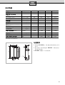
I789I789
I789I789
JKLM
18 21 24 27
I7;I7;
I7;I7;
qq
qq
380 – 415 V
380 – 415 V 380 – 415 V 400 V3~
I789I789
I789I789
ÊQÊQ
ÊQÊQ
>>
>>
ûû
ûû
OGN
12
°C
OPd
38
°C
J<PQ”M
9,9
11,6 13,2 13,9
12
°C
OPd
60
°C
J<PQ”M
5,4 6,3 7,2 7,6
*+êû*+êû
*+êû*+êû
J<PQ”M
2,6
2,6 2,6 2,6
*+ê*+ê
*+ê*+ê
qq
qq
=
J
MPa
oRrM
0,025 (0,25) 0,025 (0,25) 0,025 (0,25) 0,025 (0,25)
êê
êê
qq
qq
oOI789Ê¥GU
60
°
C
Ûr=
vSêûüý J
MPa
oRrM
0,028 (0,28) 0,035 (0,35) 0,048 (0,48) 0,064 (0,64)
4êûüý J
MPa
oRrM
0,013 (0,13)
0,020 (0,20) 0,026 (0,26) 0,035 (0,35)
T>UT>U
T>UT >U
??
??
kk
kk
VV
VV
ÙOÙO
ÙOÙO
15
°C
ÀWÀW
ÀWÀW
ÊÊ
ÊÊ
?X;?X;
?X;? X;
YY
YY
J
Ω
cm
M
≥
1300
≥
1300
≥
1300
≥
1300
I7I7
I7I7
qq
qq
ZZ
ZZ
J
MPa
oRrM
1 (10)
1 (10) 1 (10) 1 (10)
[h:>G
[°C] 35 35 35 35
NH\?NH\?
NH\?NH\?
[[
[[
hh
hh
]K]K
]K]K
;;
;;
YY
YY
[
Ω
]
–
≤
0,44
≤
0,36
≤
0,33
G
1
2
A
472
122
135
231
20
100
332
42
388
HK

Family Line
01805-2223
Siemens-Hausgeräte
Besuchen Sie uns im Internet:
http://www.siemens.de/hausgeraete
Siemens-Electrogeräte GmbH
5650038527
Printed in Germany 09/03
-
 1
1
-
 2
2
-
 3
3
-
 4
4
-
 5
5
-
 6
6
-
 7
7
-
 8
8
-
 9
9
-
 10
10
-
 11
11
-
 12
12
-
 13
13
-
 14
14
-
 15
15
-
 16
16
-
 17
17
-
 18
18
-
 19
19
-
 20
20


en otros idiomas
- français: Siemens DE27405/02 Manuel utilisateur
- italiano: Siemens DE27405/02 Manuale utente
- Deutsch: Siemens DE27405/02 Benutzerhandbuch
- Nederlands: Siemens DE27405/02 Handleiding
- português: Siemens DE27405/02 Manual do usuário
Artículos relacionados
Otros documentos
-
Kospel EPO2 Manual de usuario
-
clage DCX 12 Next L Guía de inicio rápido
-
Whirlpool ART 316/DT-V/A+ Guía del usuario
-
Dornbracht 33880889-000010 Guía de instalación
-
STIEBEL ELTRON EIL 3-7 Premium (en-fr-nl-es-pl) Operation Instruction
-
Duscholux COLLECTION 2 Maritim 451203 Installation Instructions Manual