Rockford Fosgate Punch XLC RFP2412/2812 Manual de usuario
- Tipo
- Manual de usuario

® ®
car audio
fanatics
for
punch
®
RFP-1408/1808
RFP-1410/1810
RFP-1412/1812
RFP-1415/1815
RFP-1418/1815

Dear Customer,
Congratulations on your purchase of the world's finest brand of car audio speakers. At
Rockford Fosgate we are fanatics about musical reproduction at its best, and we are
pleased you chose our product. Through years of engineering expertise, hand craftsman-
ship and critical testing procedures, we have created a wide range of products that
reproduce music with all the clarity and richness you deserve.
For maximum performance we recommend you have your new Rockford Fosgate
product installed by an Authorized Rockford Fosgate Dealer, as we provide specialized
training through Rockford Technical Training Institute (RTTI). Please read your
warranty and retain your receipt and original carton for possible future use.
Great product and competent installations are only a piece of the puzzle when it comes
to your system. Make sure that your installer is using 100% authentic installation
accessories from Connecting Punch in your installation. Connecting Punch has
everything from RCA cables and speaker wire to Power line and battery connectors.
Insist on it! After all, your new system deserves nothing but the best.
To add the finishing touch to your new Rockford Fosgate image order your Rockford
wearables, which include everything from T-shirts and jackets to hats and sunglasses.
To get a free brochure on Rockford Fosgate products and Rockford wearables, in the U.S.
call 602-967-3565 or FAX 602-967-8132. For all other countries, call +001-602-
967-3565 or FAX +001-602-967-8132.
The serial number can be found on the outside of the box. Please record it in
the space provided below as your permanent record. This will serve as
verification of your factory warranty and may become useful in recovering your
speaker if it is ever stolen.
Serial Number: ________________________________
Model Number:________________________________
If, after reading your manual, you still have questions regarding this product,
we recommend that you see your Rockford Fosgate dealer. If you need further
assistance, you can call us direct at 1-800-795-2385. Be sure to have your serial
number, model number and date of purchase available when you call.
PRACTICE SAFE SOUND™
CONTINUOUS EXPOSURE TO SOUND PRESSURE LEVELS OVER
100dB MAY CAUSE PERMANENT HEARING LOSS. HIGH
POWERED
AUTOSOUND SYSTEMS MAY PRODUCE SOUND
PRESSURE
LEVELS WELL OVER 130dB. USE COMMON SENSE
AND
PRACTICE SAFE SOUND.

TABLE OF CONTENTS
Introduction .............................................................................................1
RF Punch Woofer Contents ......................................................................1
Technical Design Features ....................................................................... 1
Stamped Basket ..................................................................................1
PVA Cone .......................................................................................... 1
Inverted Dust Cap .............................................................................. 1
Aluminum Voice Coil Former............................................................. 2
Four-Layer Voice Coil ........................................................................ 2
Dual Laminated Foam Surrounds ....................................................... 2
Hyper-Extended Pole Piece ................................................................2
Vented Bumped Back Plate ................................................................2
Installation ...............................................................................................3
Recommended Enclosures.................................................................. 3
Building An Enclosure ........................................................................ 4
Calculating Volume............................................................................ 4
Subwoofer Crossovers ........................................................................4
Wiring Configurations ........................................................................5
Specifications........................................................................................... 6
Warranty Information............................................................................... 7
International Information..........................................................................8
Welcome to Rockford Fosgate! This manual is designed to provide
information for the owner, salesperson and installer. For those of you
who want quick information on how to install this product, please turn
to the
Installation Section
of this manual or refer to the icon listed below.
Other information can be located by using the Table of Contents. We,
at Rockford Fosgate, have worked very hard to make sure all the
information in this manual is current. But, as we are constantly finding
new ways to improve our product, this information is subject to change
without notice.
GETTING STARTED
I
N
S
T
A
L
L
A
T
I
O
N
® ®
Sections marked
INSTALLATION
include “slam dunk”
assembly and wiring
directions

– 1 –
INTRODUCTION
The RF Punch Woofers are a full line of low frequency drivers sized
from 8" to 18" and are available in 4 or 8 ohm impedance. The RF
Punch woofers were designed for use primarily in small, sealed
enclosures. By utilizing the latest materials and construction tech-
niques, we are able to offer a speaker with high output at low
frequencies while requiring a minimum of operating space.
RF PUNCH WOOFER CONTENTS
RF Punch Woofer
Installation & Owner's Manual
TECHNICAL DESIGN FEATURES
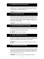
◆ Stamped Basket
The RF Punch Woofers use a stamped Cold Rolled Steel basket which
is rigid and lightweight. The basket is finished in a corrosive resistant
powder coated applied process used in many automotive applica-
tions.
THE RESULT: A lightweight and rigid woofer
◆ PVA Cone
The cone material used is spruce pulp paper. This provides the
necessary combination of weight and strength and allows high levels
of output without cone break up. The cone is treated with a water
resistant PolyVinyl Acetate (PVA) Emulsion which increases the cone
rigidity and lowers distortion.
THE RESULT: Increases cone rigidity and lowers distortion
◆ Inverted Dust Cap
The use of the inverted dust cap serves to increase the cone rigidity and
improve the power handling by forcing more air through the voice
coil.
THE RESULT: Increases cone rigidity, smooths frequency response
and prevents your friends from feeling obligated to invert them for you.

– 2 –
◆ Aluminum Voice Coil Former
The voice coil former is black, anodized aluminum for highly efficient
thermal transfer. This allows winding high temperature copper wire
in multiple layers for improved efficiency.
THE RESULT: Improves power handling by efficiently dissipating heat
◆ Four-Layer Voice Coil
Multiple layers of high temperature copper wire are wound on the
Aluminum Voice Coil for efficient thermal transfer. The massive voice
coil increases XMAX and adds to the moving mass of the speaker. This
lowers the Fs of the speaker for better low frequency response and
increases the power handling.
THE RESULT: Increases XMAX and power handling
◆ Dual Laminated Foam Surrounds
The RF Punch Woofers employ a dual laminate foam surround for the
front of the woofer's suspension. Dual lamination improves reliability
by making the woofer mechanically stronger.
THE RESULT: Adds mechanical strength
◆ Hyper-Extended Pole Piece
The pole piece has been extended to provide a more linear magnetic
field for the operation of the woofer. This lowers distortion and
provides the woofer with better low frequency response.
THE RESULT: Lowers distortion and provides better low frequency
response
◆ Vented Bumped Back Plate
The back plate has been stepped deeper to allow the woofer more
excursion without bottoming out. This enables the speaker to be used
in a smaller enclosure. Additionally, the back plate is vented with a
radiused aerodynamic back vent which efficiently and quietly circu-
lates cool air around the voice coil.
THE RESULT: More excursion and increased power handling

– 3 –
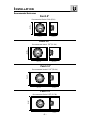
INSTALLATION
Recommended Enclosures
Punch 8"
Recommended Sealed .30ft
3
(8.50L)
D = 8"
(20.32cm)
H = 11"
(27.94cm)
W = 11"
(27.94cm)
Punch 10"
Recommended Sealed .75ft
3
(21.24L)
D = 10"
(25.40cm)
H = 14"
(35.56cm)
W = 15"
(38.10cm)
Punch 12"
Recommended Sealed 1.25ft
3
(35.40L)
D = 12"
(30.48cm)
H = 14"
(35.56cm)
W = 19-3/4"
(50.17cm)
Punch 15"
Recommended Sealed 2.5ft
3
(70.79L)
D = 12"
(30.48cm)
H = 20"
(50.80cm)
W = 25"
(63.50cm)
I
N
S
T
A
L
L
A
T
I
O
N
® ®

– 4 –
I
N
S
T
A
L
L
A
T
I
O
N
® ®
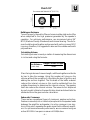
Building an Enclosure
To work properly, the walls of the enclosure must be rigid and not flex
when subjected to the high pressures generated by the speaker's
operation. For optimum performance, we recommend using 3/4"
MDF (Medium Density Fiberboard) and internal bracing. The enclo-
sure should be glued together and secured with nails or screws. MDF
is porous; therefore, it is suggested to also seal the outside walls with
polyurethane.
Calculating Volume
Calculating volume is merely a matter of measuring the dimensions
in inches and using the formula:
1728"
Height x Width x Depth
Box Volume =
(cubic feet)
If two facing sides are of uneven length, add them together and divide
by two to take the average. Using this number will give you the
volume without the necessity of calculating the box in sections and
adding the sections together. The thickness of the baffle material
reduces the internal volume so this must be subtracted from the
outside dimensions to determine the internal volume. The speaker
itself also reduces the internal volume. The amount of air displaced
by each model is listed on the specification sheet and should also be
subtracted from the gross volume calculation.
Subwoofer Crossovers
There are two operational types of crossovers, passive and active.
Passive crossovers (coils or inductors) are placed on the speaker leads
between the amplifier and speaker. An active crossover is an elec-
tronic filter which separates the audio signal fed to different amplifi-
ers.
For optimum subwoofer performance, we recommend using an
active 80-100Hz low-pass crossover at 12dB/octave.
Punch 18"
Recommended Sealed 4.0ft
3
(113.27L)
D = 14"
(35.56cm)
H = 20-1/2"
(52.0cm)
W = 32-1/2"
(82.55cm)

– 5 –
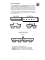
Wiring Configurations
Three configurations for connecting speakers to an amplifier
are Series, Parallel, and Series-Parallel wiring. A Series con-
figuration consists of two or more speakers wired in an string
(end to end). A Parallel configuration consists of two or more
speakers wired with the common terminals connected across
each other. A Series-Parallel configuration is a combination of
both methods. Determine which method will be compatible
with your amplifier.
R
T
= R
1
+ R
2
+ R
3
+ etc.
1 1 1 1 1
=++++ etc.
R
T
R
1
R
2
R
3
R
4
Series Wiring
Parallel Wiring
4Ω load 4Ω load
+ – + –
+ –
8Ω load
8Ω load
8Ω load
+ – + –
+ –
4Ω load
• R
T
indicates the total speaker load
• R
1
, R
2
, etc. indicates each speaker in the system
• Red dot indicates “+” terminal of
8 ohm
speaker
• Purple dot indicates “+” terminal of
4 ohm
speaker
+ –
4Ω load 4Ω load
+ –
4Ω load 4Ω load
+ –
+ –
4Ω load
+ –
+ –
Series-Parallel Wiring
I
N
S
T
A
L
L
A
T
I
O
N
® ®

– 6 –
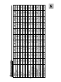
S
PECIFICATIONS
Model RFP-1408 RFP-1808 RFP-1410 RFP-1810 RFP-1412 RFP-1812 RFP-1415 RFP-1815 RFP-1418 RFP-1818
Nom. Imped. 4 8 4 8 4 8 4 8 4 8
FS (Hz) 30 32 24 26 23 25 21 23 19 20
RE (Ohm) 3.6 7.2 3.6 7.2 3.6 7.2 3.6 7.2 3.2 6.4
LE (mH) 2.5 4 2.5 4 2.5 4 2.2 3.5 3.1 4.0
QMS 4.89 5 4.08 4.7 5 5.4 6.24 5.85 5.30 5.73
QES 0.32 0.33 0.27 0.29 0.42 0.47 0.38 0.44 0.43 0.54
QTS 0.3 0.31 0.25 0.27 0.38 0.43 0.36 0.41 0.39 0.50
VAS (cu.ft) 0.883 0.883 3.437 3.437 6.28 6.28 14.34 14.34 18.5 18.5
VAS (liter) 25 25 87 87 178 178 406 406 525 525
Power (Watts RMS) 200 200 200 200 200 200 200 200 250 250
Power (Watts Peak) 400 400 400 400 400 400 400 400 500 500
SPL (dB @ 1w/1m) 85 86 87 88 90 90 93 92 91 91
X-MAX (inches) 0.31 0.31 0.31 0.31 0.31 0.31 0.31 0.31 0.33 0.33
X-MAX (mm) 8 8 8 8 8 8 8 8 8.3 8.3
Rec. Box Vol. (cu. ft.) 0.3 0.3 0.75 0.75 1.25 1.25 2.5 2.5 4 4
Speaker Dis. (cu. ft.) 0.05 0.05 0.06 0.06 0.09 0.09 0.113 0.113 0.19 0.19
Mntg. Dia. (in.) 7
1
⁄
16
7
1
⁄
16
9
5
⁄
32
9
5
⁄
32
11 11 14 14 16
17
⁄
32
16
17
⁄
32
Mntg. Depth (in.) 3
13
⁄
16
3
13
⁄
16
4
1
⁄
2
4
1
⁄
2
5
3
⁄
8
5
3
⁄
8
6
27
⁄
32
6
27
⁄
32
88
I
N
S
T
A
L
L
A
T
I
O
N
® ®

LIMITED WARRANTY INFORMATION
Rockford Corporation offers a limited warranty on Rockford Fosgate products on the
following terms:
• Length of Warranty
1 year on speakers 30 days on speaker B-stock (receipt required)
3 years on electronics 90 days on electronic B-stock (receipt required)
2 years on source units
• What is Covered
This warranty applies only to Rockford Fosgate products sold to consumers by
Authorized Rockford Fosgate Dealers in the United States of America or its
possessions. Product purchased by consumers from an Authorized Rockford
Fosgate Dealer in another country are covered only by that country’s Distributor
and not by Rockford Corporation.
• Who is Covered
This warranty covers only the original purchaser of Rockford product purchased
from an Authorized Rockford Fosgate Dealer in the United States. In order to
receive service, the purchaser must provide Rockford with a copy of the receipt
stating the customer name, dealer name, product purchased and date of purchase.
• Products found to be defective during the warranty period will be repaired or
replaced (with a product deemed to be equivalent) at Rockford's discretion.
• What is Not Covered
1. Damage caused by accident, abuse, improper operations, water, theft
2. Any cost or expense related to the removal or reinstallation of product
3. Service performed by anyone other than Rockford or an Authorized Rockford
Fosgate Service Center
4. Any product which has had the serial number defaced, altered, or removed
5. Subsequent damage to other components
6. Any product purchased outside the U.S.
7. Any product not purchased from an Authorized Rockford Fosgate Dealer
• Limit on Implied Warranties
Any implied warranties including warranties of fitness for use and merchantability
are limited in duration to the period of the express warranty set forth above. Some
states do not allow limitations on the length of an implied warranty, so this
limitation may not apply. No person is authorized to assume for Rockford Fosgate
any other liability in connection with the sale of the product.
• How to Obtain Service
Please call 1-800-669-9899 for Rockford Customer Service. You must obtain an
RA# (Return Authorization number) to return any product to Rockford Fosgate. You
are responsible for shipment of product to Rockford.
Ship to: Speakers
Rockford Acoustic Design
(Receiving-speakers)
609 Myrtle N.W.
Grand Rapids, MI 49504
RA#:_________________
Ship to: Electronics
Rockford Corporation
Warranty Repair Department
2055 E. 5th Street
Tempe, AZ 85281
RA#:_________________
– 7 –

INTERNATIONAL
I
NFORMATION
– 8 –

LEA DETENIDAMENTE LAS SIGUIENTES INSTRUCCIONES DE
INSTALACÍON DEL PRODUCTO.
Los terminales positivo y negativo de entrada están ubicados uno en
cada extremo de la carcasa. Este montaje separado previene de
posibles cortocircuitos de la señal a altos niveles de volumen. El
terminal positivo está marcado con un punto en la carcasa. Un punto
rojo indica que la impedancia del altavoz es de 8 ohmios, y un punto
violeta que es de 4 ohmios.
INTRODUCCÍON
Los woofers RF son una gama completa de drivers de baja frecuéncia
que comprenden diámetros de 8" a 15". Los Woofers RF fueron
diseñados para su utilización en caja cerrada o bass-reflex mediana.
Diseñada para ofrecer la máxima calidad, los Woofers RF ofrecen al
entusiasta principiante en sistemas de car audio, la oportunidad para
disfrutar de un bajo sólido en las bajas frecuéncias. Nuestros
ingenieros han seleccionado materiales y técnicas para la construcción
de nuestros altavoces con el objetivo de ofrecer características y
confianza comparable a otros altavoces vendidos much más caros.
TERMINALES DE ENTRADA
– 9 –

Para un buen funcionamiento las paredes del recinto han de ser
rigidas y sin flexión a altas presiones de aire. Recomendamos usar un
espesor de 1.9 cm de conglomerado de alta densidad o fibra de
media densidad. Si el recinto es muy grande es necessario reforzarlo
internamente. Las juntas deben ser encoladas y aseguradas con
tornillos o grapas. Internamente las juntas deben ser selladas con
silicona para prevenir las fugas de aire. La cola para madera es la
mejor opción. Debido a la porosidad del conglomerado de alta
densidad y la fibra es recomendable sellar exteriormente la caja con
poliuretano.
CONSTRUCCION DE UN RECINTO
CALCULO DEL VOLUMEN
Para calcular el volumen sólo se han de medir las dimensiones en
centimetros y aplicar la fórmula:
Volumen du
la caja =
Si dos caras opuestas son de diferente tamaño, súmelas y divida el
total por dos para obtener el promedio. Usando esta técnica se
ahorrara el cálculo por secciones. El espesor del material con que está
construida la caja reduce el volumen interno, de manera quer ha de
restarse de las dimensiones exteriores para determinar el volumen
interior. La cantidad de aire que ocupa cada modelo viene especificado
en la hoja de caracteristicas y también debe sustraerse para obtener
el volumen neto interior.
1000
Alto x Ancho x Profundidad
(en litros)
E
SPAÑOL
– 10 –

VEUILLEZ LIRE LES INSTRUCTIONS SUIVANTES POUR L'INSTALLATION
DE CE PRODUIT.
Les bornes positives et négatives sont fixées de part et d'autre du
saladier. Cette séparation permet d'empêcher les courts-circuits entre
les fils lors des reproductions sonores élevées. La borne positive est
repérée par un petit point de couleur sur le saladier. Un point rouge
est utilisé pour les haut-parleurs de 8Ω, un point violet pour les haut-
parleurs de 4Ω.
INTRODUCTION
Les woofers Punch sont une gamme complète de haut-parleurs de
graves allant de 20 à 46 cm et disponibles en 4Ω ou 8Ω. Les woofer
Punch ont été conçus pour être utilisé de préférence en enceintes
closes.
En utilisant les techniques et les matériaux de construction les plus
récents, nous sommes parvenus à construire un haut-parleur
fournissant un rendement élevé dans les graves tout en requérant un
volume opérationnel minimum.
BORNIERS
– 11 –

Pour fonctionner convenablement les parois du caisson doivent être
rigides lorsqu'elles sont soumises aux hautes pressions dues au
fonctionnement du haut-parleur. Nous vous recommandons d'utiliser
des panneaux de bois aggloméré à haute ou moyenne densité de
particules de type “MDF”. Ces panneaux sont disponibles dans la
plupart des magasins de bricolage. Pour un caisson de grand volume
il est recommandé de placer des renforts à l'intérieur du caisson. Les
différents côtés devront être collés (colle à bois) et vissés (ou
éventuellement cloués). Il est recommandé de mettre un joint de
silicone dans les arêtes internes du caisson afin d'éviter les fuites
d'air. Du fait de la porosité des matériaux que nous vous conseillons
il est préférable de recouvrir l'extérieur du caisson avec du
polyuréthane.
CONSTRUIRE UN CAISSON
CALCUL DU VOLUME
On calcule le volume en mesurant la dimension de chaque côté et en
utilisant la formule suivante:
Volume du
caisson =
(Litres)
Si les due côtés qui se font face n'ont pas la même longueur,
additionnez les et divisez le résultat par deux pour obtenir la
moyenne des deux longueurs. Utilisez le nombre ainsi obtenu dans
la formule pour déterminer le litrage. Cette méthode permet d'obtenir
le volume du caisson sans devoir faire de calculs compliqués de
section de volume. L'épaisseur du matériau dont est fait le caisson
réduit le volume interne de celui-ci. Lorsqu'on mesure les côtés du
caisson il ne faut donc pas oublier d'oter des mesures l'epaisseur du
matériau. Le haut-parleur lui-même diminue le volume interne du
caisson. Le volume d'air déplacé par chaque modèle de haut-parleur
est repris dans les spécifications techniques et doit également être
soustrait du volume total.
1000
Hauteur (cm) x Longueur (cm) x Largeur (cm)
F
RANCAIS
– 12 –

ANSCHLU
ββ
ββ
βTERMINALS
BITTE LESEN SIE DIESE GEBRAUCHSANLEITUNG ZUERST SORGFÄLTIG
DURCH. DAS KANN SIE VOR FALSCHEM EINSATZ, AUSFALLEN ODER
SOGAR BESCHÄDIGUNG DES PRODUKTES ODER IHRES FAHRZEUGES
SCHÜTZEN.
EINLEITUNG
Die RF-Punch Woofer sind eine komplette Produktlinie von Tief-
Frequenzlautsprechern mit Durchmesser von 20 cm bis zu 46 cm,
erhältlich in der Impendanz 4 - und 8 Ohm (Die RF Punch Woofer
wurden vorwiegend fur den Einsatz in geschlossenen Gehäuse
konstruiert). Durch die Verwendung neuester Materialien und
Produktionstechniken können wir Ihnen heute einen Lautsprecher
vorstellen, der hohe Lautstärken und tiefe Frequenzen selbst in sehr
kleinen Volumen reproduzieren kann.
Die Anschluβterminals wurden auf jeder Seite des Lautsprecherkorbes
positioniert um eventuelle Kurzschlüsse auch bei hoher Leistung
auszuschlieβen (Das Positiv-Terminal ist durch eine Farbmarkierung
gekenzeichnet). Eine rote Farbamrkierung befindet sich immer bei
einem Lautsprecher mit einer Impedanz von 8 Ohm, eine violette
Farbmarkierung zeichnet die Lautsprecher mit der Impedanz 4 Ohm.
– 13 –

D
EUTSCH
Um das Gehäuse so präzise wie möglich zu bauen, sollten die
Gehäusewände sehr steif und luftundurchlässig sein, um dem
entsehenden Luftdruck des Lautsprechers standhalten zu können.
Wir empfehlen 1,9 cm mittelverdichtete Faserplatte (MDF), die in
den meisten Baumärkten angeboten wird. Bei einem gröβeren
Gehäuse sollten Sie Versteifungen durch Holzbalken montieren.
Diese sollten – wie auch das gesamte Gehäuse – mit Holzleim
geklebt und verschraubt oder vernagelt sein. Um eine höhere Dichte
zu erreichen, empfiehlt es sich, die Kanten und Verschraubungen
mit Silikon abzudichten und das Gehäuse von innen mit einer
Hohlraumversiegelung zu behandeln.
DER GEHÄUSE BAU
VOLUMEN-BERECHNUNG
Zur Volumen-Berechung benötigen sie die genauen Maβe und
Dimensionen in Zentimetern.
Gehäuse-
Volumen =
Sollten zwei gegenüberliegende Seiten ungleich lang sein, so können
sie die Maβe zusammen rechnen und durch zwei dividieren um den
Durchschnitt zu erhalten. Dies macht Ihnen die Berechnung leichter
und Sie müssen das Gehäuse nicht in Sektionen berechnen, die Sie
danach wieder mühselig zusammen zählen müssen. Die Materialstärke
beeinfluβt natürlich auch das Innen-Volumen, so muss für eine
präzise Berechnung die Materialstärke von Auβen-Volumen
abgezogen werden. Der Lautsprecher verringert ebenfalls das Innen-
Volumen, auch er sollte natürlich heraus gerechnet werden. Jedes
Lautsprecher-Volumen ist unter “Specifications” genau aufgelistet.
1000
Höhe (cm) x Breite (cm) x Tiefe (cm)
(Kubik Liter)
– 14 –

LEGGERE CON ATTENZIONE LE SEGUENTI ISTRUZIONI PRIMA
DELL'INSTALLAZIONE DEL PRODOTTO.
I connettori di ingresso positivi e negativi sono montati sul cestello in
posizioni speculari. Il montaggio separato impedisce al segnale
musicale di cortocircuitarsi ad altissimi livelli di volume. (Il terminale
di ingresso é indicato da una marcatura colorata sul cestello.) Un
contrassengno rosso indica che l'impedenza dell'altoparlante é 8
ohm, il contrassegno viola é impiegato per i 4 ohm.
INTRODUZIONE
I woofer Punch RF sono una linea completa di altoparlanti per basse
frequenze con diametri che vanno da 20 a 46 cm e disponibili sia a
4 che a 8 ohm. (I woofer Punch RF sono progettati per il funzionamento
principale in cassa chiusa.). Impiegando le piú aggiomate tecnologie
e materiali, siamo in grado di offrire altoparlanti che possono
riprodurre un'elevata pressione sonora alle basse frequenze
mantenendo i volumi di impiego assolutamente ridotti.
CONNESSIONI DI INGRESSO
– 15 –

Per ottenere le prestazioni massime, le pareti della cassa devono
essere rigide e non flettere sotto la sollecitaxione della elevata
pressione generata dal woofer. Noi raccomandiamo l'impiego di
MDF con uno spessore minimo di 19 mm, materiale facilmente
reperibile in tutte le falegnamerle. Per casse di dimensioni molto
grandi é indispensabile prevedere dei rinforzi interni. Le giunture
devono essere incollate e fissate con viti o chiodi in abbondanza.
Intermanmente le giunture devono essere siliconate per impedire
trafilati d'aria. Anche la colla da legno funziona bene. Essendo il
MDF un materiale poroso si consiglia di sigillare l'esterno con
materiali poliuretanici.
COSTRUIRE UNA CASSA
CALCOLO DEL VOLUME
Calcolare il volume é essenzialmente solo un poroblema di
misurazione delle dimensioni in centimetri della cassa e di
applicazione della formula:
Volume della
cassa =
(litri)
1000
Alteza x Larghezza x Profonditá
Se due pareti parallele sono di dimensioni diverse (prisma),
semplicemente sommatele e dividete il risulto per due. Impiegando
il risultato ottenuto potete calcolare il volume senza dividere la cassa
i sezioni. Lo spessore del legno riduce il volume interno, per cui é
necessario sottrario dalle dimensioni esterne. Anche il volume
dell'altoparlante stesso riduce il volume della cassa e deve essere
sottratto. Il volume che ciascun altoparlante contribuisce a togliere
dalla cassa é indicato nelle tabelle con le specifiche.
I
TALIANO
– 16 –

11/96
LIT9778
Rockford Fosgate
Rockford Corporation
546 South Rockford Drive
Tempe, Arizona 85281 U.S.A.
In U.S.A., (602) 967-3565
In Europe, Fax (49) 4207-801250
In Japan, Fax (81) 559-79-1265
MADE IN THE USA
This product is designed, developed and assembled in the USA by a dedicated
group of American workers. The majority of the components used in the
construction of this product are produced by American companies. However, due
to the global nature of their manufacturing facilities and the loudspeaker parts
industry in general, some parts may be manufactured in other countries.
Transcripción de documentos
® ® RFP-1408/1808 RFP-1410/1810 RFP-1412/1812 RFP-1415/1815 punch RFP-1418/1815 ® car audio for fanatics Dear Customer, Congratulations on your purchase of the world's finest brand of car audio speakers. At Rockford Fosgate we are fanatics about musical reproduction at its best, and we are pleased you chose our product. Through years of engineering expertise, hand craftsmanship and critical testing procedures, we have created a wide range of products that reproduce music with all the clarity and richness you deserve. For maximum performance we recommend you have your new Rockford Fosgate product installed by an Authorized Rockford Fosgate Dealer, as we provide specialized training through Rockford Technical Training Institute (RTTI). Please read your warranty and retain your receipt and original carton for possible future use. Great product and competent installations are only a piece of the puzzle when it comes to your system. Make sure that your installer is using 100% authentic installation accessories from Connecting Punch in your installation. Connecting Punch has everything from RCA cables and speaker wire to Power line and battery connectors. Insist on it! After all, your new system deserves nothing but the best. To add the finishing touch to your new Rockford Fosgate image order your Rockford wearables, which include everything from T-shirts and jackets to hats and sunglasses. To get a free brochure on Rockford Fosgate products and Rockford wearables, in the U.S. call 602-967-3565 or FAX 602-967-8132. For all other countries, call +001-602967-3565 or FAX +001-602-967-8132. PRACTICE SAFE SOUND™ CONTINUOUS EXPOSURE TO SOUND PRESSURE LEVELS OVER 100dB MAY CAUSE PERMANENT HEARING LOSS. HIGH POWERED AUTOSOUND SYSTEMS MAY PRODUCE SOUND PRESSURE LEVELS WELL OVER 130dB. USE COMMON SENSE AND PRACTICE SAFE SOUND. If, after reading your manual, you still have questions regarding this product, we recommend that you see your Rockford Fosgate dealer. If you need further assistance, you can call us direct at 1-800-795-2385. Be sure to have your serial number, model number and date of purchase available when you call. The serial number can be found on the outside of the box. Please record it in the space provided below as your permanent record. This will serve as verification of your factory warranty and may become useful in recovering your speaker if it is ever stolen. Serial Number: ________________________________ Model Number: ________________________________ TABLE OF CONTENTS Introduction ............................................................................................. 1 RF Punch Woofer Contents ...................................................................... 1 Technical Design Features ....................................................................... 1 Stamped Basket .................................................................................. 1 PVA Cone .......................................................................................... 1 Inverted Dust Cap .............................................................................. 1 Aluminum Voice Coil Former ............................................................. 2 Four-Layer Voice Coil ........................................................................ 2 Dual Laminated Foam Surrounds ....................................................... 2 Hyper-Extended Pole Piece ................................................................ 2 Vented Bumped Back Plate ................................................................ 2 Installation ............................................................................................... 3 Recommended Enclosures .................................................................. 3 Building An Enclosure ........................................................................ 4 Calculating Volume ............................................................................ 4 Subwoofer Crossovers ........................................................................ 4 Wiring Configurations ........................................................................ 5 Specifications ........................................................................................... 6 Warranty Information ............................................................................... 7 International Information .......................................................................... 8 G E T T I N G S TA R T E D Welcome to Rockford Fosgate! This manual is designed to provide information for the owner, salesperson and installer. For those of you who want quick information on how to install this product, please turn to the Installation Section of this manual or refer to the icon listed below. Other information can be located by using the Table of Contents. We, at Rockford Fosgate, have worked very hard to make sure all the information in this manual is current. But, as we are constantly finding new ways to improve our product, this information is subject to change without notice. ® ® I N S T A L L A T I O N Sections marked INSTALLATION include “slam dunk” assembly and wiring directions INTRODUCTION The RF Punch Woofers are a full line of low frequency drivers sized from 8" to 18" and are available in 4 or 8 ohm impedance. The RF Punch woofers were designed for use primarily in small, sealed enclosures. By utilizing the latest materials and construction techniques, we are able to offer a speaker with high output at low frequencies while requiring a minimum of operating space. RF P UNCH W OOFER C ONTENTS RF Punch Woofer Installation & Owner's Manual TECHNICAL D E S I G N F E AT U R E S ◆ Stamped Basket The RF Punch Woofers use a stamped Cold Rolled Steel basket which is rigid and lightweight. The basket is finished in a corrosive resistant powder coated applied process used in many automotive applications. THE RESULT: A lightweight and rigid woofer ◆ PVA Cone The cone material used is spruce pulp paper. This provides the necessary combination of weight and strength and allows high levels of output without cone break up. The cone is treated with a water resistant PolyVinyl Acetate (PVA) Emulsion which increases the cone rigidity and lowers distortion. THE RESULT: Increases cone rigidity and lowers distortion ◆ Inverted Dust Cap The use of the inverted dust cap serves to increase the cone rigidity and improve the power handling by forcing more air through the voice coil. THE RESULT: Increases cone rigidity, smooths frequency response and prevents your friends from feeling obligated to invert them for you. –1– ◆ Aluminum Voice Coil Former The voice coil former is black, anodized aluminum for highly efficient thermal transfer. This allows winding high temperature copper wire in multiple layers for improved efficiency. THE RESULT: Improves power handling by efficiently dissipating heat ◆ Four-Layer Voice Coil Multiple layers of high temperature copper wire are wound on the Aluminum Voice Coil for efficient thermal transfer. The massive voice coil increases XMAX and adds to the moving mass of the speaker. This lowers the Fs of the speaker for better low frequency response and increases the power handling. THE RESULT: Increases XMAX and power handling ◆ Dual Laminated Foam Surrounds The RF Punch Woofers employ a dual laminate foam surround for the front of the woofer's suspension. Dual lamination improves reliability by making the woofer mechanically stronger. THE RESULT: Adds mechanical strength ◆ Hyper-Extended Pole Piece The pole piece has been extended to provide a more linear magnetic field for the operation of the woofer. This lowers distortion and provides the woofer with better low frequency response. THE RESULT: Lowers distortion and provides better low frequency response ◆ Vented Bumped Back Plate The back plate has been stepped deeper to allow the woofer more excursion without bottoming out. This enables the speaker to be used in a smaller enclosure. Additionally, the back plate is vented with a radiused aerodynamic back vent which efficiently and quietly circulates cool air around the voice coil. THE RESULT: More excursion and increased power handling –2– ® INSTALLATION Recommended Enclosures Punch 8" H = 11" (27.94cm) Recommended Sealed .30ft3 (8.50L) D = 8" (20.32cm) W = 11" (27.94cm) Punch 10" H = 14" (35.56cm) Recommended Sealed .75ft3 (21.24L) W = 15" (38.10cm) D = 10" (25.40cm) Punch 12" H = 14" (35.56cm) Recommended Sealed 1.25ft3 (35.40L) W = 19-3/4" (50.17cm) D = 12" (30.48cm) Punch 15" H = 20" (50.80cm) Recommended Sealed 2.5ft3 (70.79L) W = 25" (63.50cm) D = 12" (30.48cm) –3– ® I N S T A L L A T I O N ® ® Punch 18" H = 20-1/2" (52.0cm) Recommended Sealed 4.0ft3 (113.27L) W = 32-1/2" (82.55cm) D = 14" (35.56cm) Building an Enclosure To work properly, the walls of the enclosure must be rigid and not flex when subjected to the high pressures generated by the speaker's operation. For optimum performance, we recommend using 3/4" MDF (Medium Density Fiberboard) and internal bracing. The enclosure should be glued together and secured with nails or screws. MDF is porous; therefore, it is suggested to also seal the outside walls with polyurethane. Calculating Volume Calculating volume is merely a matter of measuring the dimensions in inches and using the formula: Box Volume = Height x Width x Depth (cubic feet) 1728" If two facing sides are of uneven length, add them together and divide by two to take the average. Using this number will give you the volume without the necessity of calculating the box in sections and adding the sections together. The thickness of the baffle material reduces the internal volume so this must be subtracted from the outside dimensions to determine the internal volume. The speaker itself also reduces the internal volume. The amount of air displaced by each model is listed on the specification sheet and should also be subtracted from the gross volume calculation. Subwoofer Crossovers There are two operational types of crossovers, passive and active. Passive crossovers (coils or inductors) are placed on the speaker leads between the amplifier and speaker. An active crossover is an electronic filter which separates the audio signal fed to different amplifiers. For optimum subwoofer performance, we recommend using an active 80-100Hz low-pass crossover at 12dB/octave. –4– I N S T A L L A T I O N ® Wiring Configurations Three configurations for connecting speakers to an amplifier are Series, Parallel, and Series-Parallel wiring. A Series configuration consists of two or more speakers wired in an string (end to end). A Parallel configuration consists of two or more speakers wired with the common terminals connected across each other. A Series-Parallel configuration is a combination of both methods. Determine which method will be compatible with your amplifier. Series Wiring Parallel Wiring 1 RT = R1 + R2 + R3 + etc. RT = 1 + R1 – + + 4Ω load – + R2 + – 8Ω load + 1 + 1 R3 – + 4Ω load + – + 4Ω load • • • • + – + – + 4Ω load – 4Ω load + – 4Ω load RT indicates the total speaker load R1, R2, etc. indicates each speaker in the system Red dot indicates “+” terminal of 8 ohm speaker Purple dot indicates “+” terminal of 4 ohm speaker –5– + etc. – – 8Ω load Series-Parallel Wiring – 1 R4 4Ω load 8Ω load 4Ω load + ® I N S T A L L A T I O N Model Nom. Imped. FS (Hz) RE (Ohm) LE (mH) QMS QES QTS VAS (cu.ft) VAS (liter) Power (Watts RMS) Power (Watts Peak) SPL (dB @ 1w/1m) X-MAX (inches) X-MAX (mm) Rec. Box Vol. (cu. ft.) Speaker Dis. (cu. ft.) Mntg. Dia. (in.) Mntg. Depth (in.) RFP-1408 4 30 3.6 2.5 4.89 0.32 0.3 0.883 25 200 400 85 0.31 8 0.3 0.05 71⁄16 313⁄16 S P E C I F I C AT I O N S RFP-1808 8 32 7.2 4 5 0.33 0.31 0.883 25 200 400 86 0.31 8 0.3 0.05 71⁄16 313⁄16 RFP-1410 4 24 3.6 2.5 4.08 0.27 0.25 3.437 87 200 400 87 0.31 8 0.75 0.06 95⁄32 41⁄2 RFP-1810 RFP-1412 RFP-1812 8 4 8 26 23 25 7.2 3.6 7.2 4 2.5 4 4.7 5 5.4 0.29 0.42 0.47 0.27 0.38 0.43 3.437 6.28 6.28 87 178 178 200 200 200 400 400 400 88 90 90 0.31 0.31 0.31 8 8 8 0.75 1.25 1.25 0.06 0.09 0.09 5 9 ⁄32 11 11 1 3 4 ⁄2 5 ⁄8 5 3⁄8 RFP-1415 RFP-1815 RFP-1418 RFP-1818 4 8 4 8 21 23 19 20 3.6 7.2 3.2 6.4 2.2 3.5 3.1 4.0 6.24 5.85 5.30 5.73 0.38 0.44 0.43 0.54 0.36 0.41 0.39 0.50 14.34 14.34 18.5 18.5 406 406 525 525 200 200 250 250 400 400 500 500 93 92 91 91 0.31 0.31 0.33 0.33 8 8 8.3 8.3 2.5 2.5 4 4 0.113 0.113 0.19 0.19 17 14 14 16 ⁄32 1617⁄32 627⁄32 627⁄32 8 8 ® –6– ® I N S T A L L A T I O N L IMITED W A R R A N T Y I N F O R M AT I O N Rockford Corporation offers a limited warranty on Rockford Fosgate products on the following terms: • Length of Warranty 1 year on speakers 3 years on electronics 2 years on source units 30 days on speaker B-stock (receipt required) 90 days on electronic B-stock (receipt required) • What is Covered This warranty applies only to Rockford Fosgate products sold to consumers by Authorized Rockford Fosgate Dealers in the United States of America or its possessions. Product purchased by consumers from an Authorized Rockford Fosgate Dealer in another country are covered only by that country’s Distributor and not by Rockford Corporation. • Who is Covered This warranty covers only the original purchaser of Rockford product purchased from an Authorized Rockford Fosgate Dealer in the United States. In order to receive service, the purchaser must provide Rockford with a copy of the receipt stating the customer name, dealer name, product purchased and date of purchase. • Products found to be defective during the warranty period will be repaired or replaced (with a product deemed to be equivalent) at Rockford's discretion. • What is Not Covered 1. Damage caused by accident, abuse, improper operations, water, theft 2. Any cost or expense related to the removal or reinstallation of product 3. Service performed by anyone other than Rockford or an Authorized Rockford Fosgate Service Center 4. Any product which has had the serial number defaced, altered, or removed 5. Subsequent damage to other components 6. Any product purchased outside the U.S. 7. Any product not purchased from an Authorized Rockford Fosgate Dealer • Limit on Implied Warranties Any implied warranties including warranties of fitness for use and merchantability are limited in duration to the period of the express warranty set forth above. Some states do not allow limitations on the length of an implied warranty, so this limitation may not apply. No person is authorized to assume for Rockford Fosgate any other liability in connection with the sale of the product. • How to Obtain Service Please call 1-800-669-9899 for Rockford Customer Service. You must obtain an RA# (Return Authorization number) to return any product to Rockford Fosgate. You are responsible for shipment of product to Rockford. Ship to: Speakers Ship to: Electronics Rockford Acoustic Design Rockford Corporation (Receiving-speakers) Warranty Repair Department 609 Myrtle N.W. 2055 E. 5th Street Grand Rapids, MI 49504 Tempe, AZ 85281 RA#:_________________ RA#:_________________ –7– A A TI N T M O ER IO R N T N FO IN A L IN –8– LEA DETENIDAMENTE LAS SIGUIENTES INSTRUCCIONES DE INSTALACÍON DEL PRODUCTO. INTRODUCCÍON Los woofers RF son una gama completa de drivers de baja frecuéncia que comprenden diámetros de 8" a 15". Los Woofers RF fueron diseñados para su utilización en caja cerrada o bass-reflex mediana. Diseñada para ofrecer la máxima calidad, los Woofers RF ofrecen al entusiasta principiante en sistemas de car audio, la oportunidad para disfrutar de un bajo sólido en las bajas frecuéncias. Nuestros ingenieros han seleccionado materiales y técnicas para la construcción de nuestros altavoces con el objetivo de ofrecer características y confianza comparable a otros altavoces vendidos much más caros. TERMINALES DE ENTRADA Los terminales positivo y negativo de entrada están ubicados uno en cada extremo de la carcasa. Este montaje separado previene de posibles cortocircuitos de la señal a altos niveles de volumen. El terminal positivo está marcado con un punto en la carcasa. Un punto rojo indica que la impedancia del altavoz es de 8 ohmios, y un punto violeta que es de 4 ohmios. –9– Para calcular el volumen sólo se han de medir las dimensiones en centimetros y aplicar la fórmula: Volumen du la caja = Alto x Ancho x Profundidad 1000 (en litros) Si dos caras opuestas son de diferente tamaño, súmelas y divida el total por dos para obtener el promedio. Usando esta técnica se ahorrara el cálculo por secciones. El espesor del material con que está construida la caja reduce el volumen interno, de manera quer ha de restarse de las dimensiones exteriores para determinar el volumen interior. La cantidad de aire que ocupa cada modelo viene especificado en la hoja de caracteristicas y también debe sustraerse para obtener el volumen neto interior. CONSTRUCCION DE UN RECINTO Para un buen funcionamiento las paredes del recinto han de ser rigidas y sin flexión a altas presiones de aire. Recomendamos usar un espesor de 1.9 cm de conglomerado de alta densidad o fibra de media densidad. Si el recinto es muy grande es necessario reforzarlo internamente. Las juntas deben ser encoladas y aseguradas con tornillos o grapas. Internamente las juntas deben ser selladas con silicona para prevenir las fugas de aire. La cola para madera es la mejor opción. Debido a la porosidad del conglomerado de alta densidad y la fibra es recomendable sellar exteriormente la caja con poliuretano. – 10 – E SPAÑOL CALCULO DEL VOLUMEN VEUILLEZ LIRE LES INSTRUCTIONS SUIVANTES POUR L'INSTALLATION DE CE PRODUIT. I NTRODUCTION Les woofers Punch sont une gamme complète de haut-parleurs de graves allant de 20 à 46 cm et disponibles en 4Ω ou 8Ω. Les woofer Punch ont été conçus pour être utilisé de préférence en enceintes closes. En utilisant les techniques et les matériaux de construction les plus récents, nous sommes parvenus à construire un haut-parleur fournissant un rendement élevé dans les graves tout en requérant un volume opérationnel minimum. B ORNIERS Les bornes positives et négatives sont fixées de part et d'autre du saladier. Cette séparation permet d'empêcher les courts-circuits entre les fils lors des reproductions sonores élevées. La borne positive est repérée par un petit point de couleur sur le saladier. Un point rouge est utilisé pour les haut-parleurs de 8Ω, un point violet pour les hautparleurs de 4Ω. – 11 – C ALCUL DU VOLUME On calcule le volume en mesurant la dimension de chaque côté et en utilisant la formule suivante: Volume du caisson = Hauteur (cm) x Longueur (cm) x Largeur (cm) 1000 (Litres) CONSTRUIRE UN CAISSON Pour fonctionner convenablement les parois du caisson doivent être rigides lorsqu'elles sont soumises aux hautes pressions dues au fonctionnement du haut-parleur. Nous vous recommandons d'utiliser des panneaux de bois aggloméré à haute ou moyenne densité de particules de type “MDF”. Ces panneaux sont disponibles dans la plupart des magasins de bricolage. Pour un caisson de grand volume il est recommandé de placer des renforts à l'intérieur du caisson. Les différents côtés devront être collés (colle à bois) et vissés (ou éventuellement cloués). Il est recommandé de mettre un joint de silicone dans les arêtes internes du caisson afin d'éviter les fuites d'air. Du fait de la porosité des matériaux que nous vous conseillons il est préférable de recouvrir l'extérieur du caisson avec du polyuréthane. – 12 – FRANCAIS Si les due côtés qui se font face n'ont pas la même longueur, additionnez les et divisez le résultat par deux pour obtenir la moyenne des deux longueurs. Utilisez le nombre ainsi obtenu dans la formule pour déterminer le litrage. Cette méthode permet d'obtenir le volume du caisson sans devoir faire de calculs compliqués de section de volume. L'épaisseur du matériau dont est fait le caisson réduit le volume interne de celui-ci. Lorsqu'on mesure les côtés du caisson il ne faut donc pas oublier d'oter des mesures l'epaisseur du matériau. Le haut-parleur lui-même diminue le volume interne du caisson. Le volume d'air déplacé par chaque modèle de haut-parleur est repris dans les spécifications techniques et doit également être soustrait du volume total. BITTE LESEN SIE DIESE GEBRAUCHSANLEITUNG ZUERST SORGFÄLTIG DURCH. DAS KANN SIE VOR FALSCHEM EINSATZ, AUSFALLEN ODER SOGAR BESCHÄDIGUNG DES PRODUKTES ODER IHRES FAHRZEUGES SCHÜTZEN. E INLEITUNG Die RF-Punch Woofer sind eine komplette Produktlinie von TiefFrequenzlautsprechern mit Durchmesser von 20 cm bis zu 46 cm, erhältlich in der Impendanz 4 - und 8 Ohm (Die RF Punch Woofer wurden vorwiegend fur den Einsatz in geschlossenen Gehäuse konstruiert). Durch die Verwendung neuester Materialien und Produktionstechniken können wir Ihnen heute einen Lautsprecher vorstellen, der hohe Lautstärken und tiefe Frequenzen selbst in sehr kleinen Volumen reproduzieren kann. ANSCHLUβTERMINALS Die Anschluβterminals wurden auf jeder Seite des Lautsprecherkorbes positioniert um eventuelle Kurzschlüsse auch bei hoher Leistung auszuschlieβen (Das Positiv-Terminal ist durch eine Farbmarkierung gekenzeichnet). Eine rote Farbamrkierung befindet sich immer bei einem Lautsprecher mit einer Impedanz von 8 Ohm, eine violette Farbmarkierung zeichnet die Lautsprecher mit der Impedanz 4 Ohm. – 13 – V OLUMEN -B ERECHNUNG Zur Volumen-Berechung benötigen sie die genauen Maβe und Dimensionen in Zentimetern. GehäuseVolumen = Höhe (cm) x Breite (cm) x Tiefe (cm) 1000 (Kubik Liter) Sollten zwei gegenüberliegende Seiten ungleich lang sein, so können sie die Maβe zusammen rechnen und durch zwei dividieren um den Durchschnitt zu erhalten. Dies macht Ihnen die Berechnung leichter und Sie müssen das Gehäuse nicht in Sektionen berechnen, die Sie danach wieder mühselig zusammen zählen müssen. Die Materialstärke beeinfluβt natürlich auch das Innen-Volumen, so muss für eine präzise Berechnung die Materialstärke von Auβen-Volumen abgezogen werden. Der Lautsprecher verringert ebenfalls das InnenVolumen, auch er sollte natürlich heraus gerechnet werden. Jedes Lautsprecher-Volumen ist unter “Specifications” genau aufgelistet. D ER G EHÄUSE B AU – 14 – DEUTSCH Um das Gehäuse so präzise wie möglich zu bauen, sollten die Gehäusewände sehr steif und luftundurchlässig sein, um dem entsehenden Luftdruck des Lautsprechers standhalten zu können. Wir empfehlen 1,9 cm mittelverdichtete Faserplatte (MDF), die in den meisten Baumärkten angeboten wird. Bei einem gröβeren Gehäuse sollten Sie Versteifungen durch Holzbalken montieren. Diese sollten – wie auch das gesamte Gehäuse – mit Holzleim geklebt und verschraubt oder vernagelt sein. Um eine höhere Dichte zu erreichen, empfiehlt es sich, die Kanten und Verschraubungen mit Silikon abzudichten und das Gehäuse von innen mit einer Hohlraumversiegelung zu behandeln. LEGGERE CON ATTENZIONE LE SEGUENTI ISTRUZIONI PRIMA DELL'INSTALLAZIONE DEL PRODOTTO. INTRODUZIONE I woofer Punch RF sono una linea completa di altoparlanti per basse frequenze con diametri che vanno da 20 a 46 cm e disponibili sia a 4 che a 8 ohm. (I woofer Punch RF sono progettati per il funzionamento principale in cassa chiusa.). Impiegando le piú aggiomate tecnologie e materiali, siamo in grado di offrire altoparlanti che possono riprodurre un'elevata pressione sonora alle basse frequenze mantenendo i volumi di impiego assolutamente ridotti. CONNESSIONI DI INGRESSO I connettori di ingresso positivi e negativi sono montati sul cestello in posizioni speculari. Il montaggio separato impedisce al segnale musicale di cortocircuitarsi ad altissimi livelli di volume. (Il terminale di ingresso é indicato da una marcatura colorata sul cestello.) Un contrassengno rosso indica che l'impedenza dell'altoparlante é 8 ohm, il contrassegno viola é impiegato per i 4 ohm. – 15 – CALCOLO DEL VOLUME Calcolare il volume é essenzialmente solo un poroblema di misurazione delle dimensioni in centimetri della cassa e di applicazione della formula: Volume della cassa = Alteza x Larghezza x Profonditá 1000 (litri) Se due pareti parallele sono di dimensioni diverse (prisma), semplicemente sommatele e dividete il risulto per due. Impiegando il risultato ottenuto potete calcolare il volume senza dividere la cassa i sezioni. Lo spessore del legno riduce il volume interno, per cui é necessario sottrario dalle dimensioni esterne. Anche il volume dell'altoparlante stesso riduce il volume della cassa e deve essere sottratto. Il volume che ciascun altoparlante contribuisce a togliere dalla cassa é indicato nelle tabelle con le specifiche. COSTRUIRE UNA CASSA Per ottenere le prestazioni massime, le pareti della cassa devono essere rigide e non flettere sotto la sollecitaxione della elevata pressione generata dal woofer. Noi raccomandiamo l'impiego di MDF con uno spessore minimo di 19 mm, materiale facilmente reperibile in tutte le falegnamerle. Per casse di dimensioni molto grandi é indispensabile prevedere dei rinforzi interni. Le giunture devono essere incollate e fissate con viti o chiodi in abbondanza. Intermanmente le giunture devono essere siliconate per impedire trafilati d'aria. Anche la colla da legno funziona bene. Essendo il MDF un materiale poroso si consiglia di sigillare l'esterno con materiali poliuretanici. ITALIANO – 16 – MADE IN THE USA This product is designed, developed and assembled in the USA by a dedicated group of American workers. The majority of the components used in the construction of this product are produced by American companies. However, due to the global nature of their manufacturing facilities and the loudspeaker parts industry in general, some parts may be manufactured in other countries. Rockford Fosgate Rockford Corporation 546 South Rockford Drive Tempe, Arizona 85281 U.S.A. In U.S.A., (602) 967-3565 In Europe, Fax (49) 4207-801250 In Japan, Fax (81) 559-79-1265 11/96 LIT9778-
 1
1
-
 2
2
-
 3
3
-
 4
4
-
 5
5
-
 6
6
-
 7
7
-
 8
8
-
 9
9
-
 10
10
-
 11
11
-
 12
12
-
 13
13
-
 14
14
-
 15
15
-
 16
16
-
 17
17
-
 18
18
-
 19
19
-
 20
20


Rockford Fosgate Punch XLC RFP2412/2812 Manual de usuario
- Tipo
- Manual de usuario
en otros idiomas
Artículos relacionados
-
Rockford Fosgate Punch HE RFP3815 Installation & Operation Manual
-
Rockford Fosgate Punch XLC RFP2812 Installation & Operation Manual
-
 Rockford Fosgate Punch RFR2215 Installation & Operation Manual
-
 Rockford Fosgate T115D4 Installation & Operation Manual
-
-
Rockford Fosgate RFP4215 Manual de usuario
-
 Rockford Fosgate RM18D4B Manual de usuario


