ATEN CE600 Guía de inicio rápido
- Categoría
- Conmutadores KVM
- Tipo
- Guía de inicio rápido
Este manual también es adecuado para

CE600/CE602 DVI KVM Extender User Instructions
Système d'extension KVM DVI CE600/CE602 – manuel d’utilisation
CE600/CE602 DVI-KVM-Verlängerung Bedienungsanleitung
Sistema de extensión KVM DVI CE600/CE602 instrucciones para el usuario
Requirements
Console
• ADVIsinglelinkorduallinkmonitorcapableofthehighestresolutionyouwillbe
usingonanymonitorintheinstallation.
• AUSBkeyboard
• AUSBmouse
• Stereomicrophoneandstereospeakers(optional)
Computers
Thefollowingequipmentmustbeinstalledoneachcomputerthatistobeconnectedto
thesystem:
• ADVIport
• 2USBportsforthemouseandkeyboard
• Microphoneandspeakerports(optional)
Cables
• Foroptimalsignalintegrity,andtosimplifythelayout,westronglyrecommendthat
youusethehighqualitycustomKVMCablethatisprovidedwiththispackage.
• Cat5ecableisrequiredtoconnecttheLocalandRemoteCE600/CE602Units.
Cableofalowerstandardwillresultindegradingofthevideosignal.Westrongly
recommendCat5ecable.
• Forbetterqualityoverlongerdistances,wesuggestusing2L-2801(350MHz)Low
SkewCable
Maximum Cable Distances
Connection Distance
ComputertoLocalUnit(CE600L/CE602L) 5m
LocalUnit(CE600L/CE602L)toRemoteUnit
(CE600R/CE602R)
60 m
RemoteUnit(CE600R/CE602R)tomonitor 5m
Conguration minimale
Console
• MoniteurDVISinglelinkouDuallinkprenantenchargelaplushauterésolution
utiliséesurlesordinateursàinstaller
• UnclavierUSB
• UnesourisUSB
• Microphonestéréoethaut-parleursstéréo(enoption)
Ordinateurs
Lescomposantssuivantsdoiventêtreinstalléssurchaqueordinateuràconnecterau
système:
• UnportDVI
• 2portsUSBpourlasourisetleclavier
• Portspourhaut-parleursetmicrophone(facultatifs)
Câbles
• Pourassureruneréceptionoptimaledusignaletsimplierl'installation,ilest
fortementrecommandéd'utiliserlecâbleKVMspéciquedehautequalitéfourni
aveccesystèmed'extension.
• Laconnexionentrel’unitélocaleetl’unitédistantedusystèmeCE600/CE602
requiertuncâbledecatégorie5e.Uncâbledecatégorieinférieurerisquede
dégraderlesignalvidéo.Nousvousrecommandonsfortementd'utiliseruncâblede
catégorie5e.
• Pourunemeilleurequalitésurdesdistancesplusimportantes,nousvoussuggérons
d’utiliseruncâbleàfaibledéphasage2L-2801(350MHz)
Longueur de câble maximale
Connexion Distance
Ordinateuràunitélocale(CE600L/CE602L) 5m
Unitélocale(CE600L/CE602L)à unité distante(CE600R/
CE602R)
60 m
Unitédistante(CE600R/CE602R)àmoniteur 5m
Voraussetzungen
Konsole
• EinDVI-Monitor(SingleLinkoderDualLink),derinderLageist,diehöchste
Auösungdarzustellen,dieSieaufeinemderzuinstallierendenMonitoreverwenden
möchten.
• EineUSB-Tastatur
• EineUSB-Maus
• Stereo-MikrofonundStereo-Lautsprecher(optional)
Computer
AufdenComputern,diemitdemSystemverbundenwerdensollen,mussmindestens
Folgendesinstalliertsein:
• EinDVI-Port
• 2USB-AnschlüssefürTastaturundMaus
• Lautsprecher-undMikrofonanschlussbuchsen(optional)
Kabel
• ZurVereinfachungdesAufbausempfehlenwir,dassSiedasmitgelieferte,
hochwertige,individuelleKVM-KabelsetdesHerstellersverwenden.
• ZurVerbindungderlokalenundentferntenCE600-/CE602-GerätewirdeinKat.-5e-
Kabelbenötigt.KabelgeringererStandardsführenzuschlechtererBildqualität.Um
optimaleErgebnissezuerzielen,empfehlenwirKat-5e-Kabel.
• ZurbesserenÜbertragungüberlängereWegeempfehlenwirKabeldesTyps2L-
2801(350MHz)mitgeringerenLaufzeitunterschieden.
Maximale Kabellängen
Verbindung Entfernung
ComputerzumlokalemGerät(CE600L/CE602L) 5m
LokalesGerät(CE600L / CE602L)zum entferntemGerät
(CE600R/CE602R)
60 m
EntferntesGerät(CE600R/CE602R)zumMonitor 5m
Requisitos
Consola
• UnmonitorDVISingleLinkcapazderepresentarlaresoluciónmáselevadaque
vayaausarconcualquieradelosmonitoresinstalados
• UntecladoUSB
• UnmouseUSB
• Micrófonoestéreoyaltavocesestéreo(opcional)
PCs
Encadacomputadoraquevayaaconectaralsistemasetienenqueinstalarlos
siguientescomponentes:
• UnpuertoDVI
• 2puertosUSBparatecladoymouse
• Puertosparaaltavocesymicrófono(opcionales)
Cables
• Paragarantizarunarecepciónoptimadelaseñalysimplicarelsistema,le
recomendamosqueuseelcableKVMpersonalizadodealtacalidadincluidoconel
dispositivo.
• SerequiereuncabledeCat.5eparaconectarlasunidadeslocalyremotaCE600
/CE602.Uncabledecalidadinferiortiendeadeteriorarlaseñalgráca.Le
recomendamosvivamentequeempleeuncabledeCat.5e.
• Paramejorarlacalidadalargasdistancias,lerecomendamosutilizarcable2L-
2801(350MHz)conmínimasdiferenciasenlostiemposdepropagación.
Longitudes máximas de cables
Conexión Distancia
Computadoraaunidadlocal(CE600L/CE602L) 5m
Unidadlocal(CE600L/CE602L)aunidadremota(CE600R/
CE602R)
60 m
Unidadremota(CE600R/CE602R)almonitor 5m
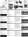
Hardware Review
A
CE600L / CE602L (Local Unit) Front View
1.DVIport
2.USBTypeBInput
3.AudioPorts
4.RS-232SerialPort
5.LEDs
CE600R / CE602R (Remote Unit) Front View
1.EQSwitch
2.RS-232SerialPort
3.LEDs
CE600L / CE602L (Local Unit) Rear View
1.F/WUpgradeSwitch
2.PowerJack
3.Sub/Main
CE600R / CE602R (Remote Unit) Rear View
1.PowerJack
2.USB
3.AudioPorts
4.Sub/Main
5.DVIport
Hardware Installation
Rack Mounting
B
Forconvenienceandexibility,theCE600/CE602canbemountedonsystemracks.
Torackmountaunitdothefollowing:
1.UsingthescrewsprovidedintheRackMountKit,screwthemountingbracketinto
thetoporbottomoftheunit.
2.Screwthebracketintoanyconvenientlocationontherack.
Note: Thesescrewsarenotprovided.WerecommendthatyouuseM5x12Phillips
TypeIcross,recessedtypescrews.
Description de l’appareil
A
CE600L / CE602L (unité locale) – Vue avant
1.PortDVI
2.EntréeUSBdetypeB
3.Portsaudio
4.PortsérieRS-232
5.Voyants
CE600R / CE602R (unité distante) – Vue avant
1.BoutonEQ
2.PortsérieRS-232
3.Voyants
CE600L / CE602L (unité locale) – Vue arrière
1.Commutateurdemiseàniveaudumicroprogramme
2.Prised’alimentation
3.Secondaire/Principal
CE600R / CE602R (unité distante) – Vue arrière
1.Prised’alimentation
2.USB
3.Portsaudio
4.Secondaire/Principal
5.PortDVI
Installation du matériel
Montage sur bâti
B
Pourunplusgrandconfort,lessystèmesCE600/CE602peuventêtremontéssur
bâti.Pourmonteruneconsolesurbâti,procédezcommesuit:
1.Vissezlesupportdemontagesurbâtisurlapartiesupérieureouinférieurede
l'appareilàl'aidedesvisfournies.
2.Vissezlesupportaubâtiàn’importequelendroitvoussemblantadapté.
Remarque:lesvisnesontpasfournies.Ilestconseilléd'utiliser12visM5à
empreintecruciformePhillipsdetype1.
Hardwareübersicht
A
CE600L / CE602L (lokales Gerät) Vorderseite
1.DVI-Anschluss
2.USB-Eingang,TypB
3.Audioports
4.SeriellerRS-232-Port
5.LED-Anzeigen
CE600R / CE602R (entferntes Gerät) Vorderseite
1.EQ-Schalter
2.SeriellerRS-232-Port
3.LED-Anzeigen
CE600L / CE602L (lokales Gerät) Rückseite
1.SchalterfürFirmwareaktualisierung
2.Stromeingangsbuchse
3.Sub/Main
CE600R / CE602R (entferntes Gerät) Rückseite
1.Stromeingangsbuchse
2.USB
3.Audioports
4.Sub/Main
5.DVI-Anschluss
Hardware installieren
Rack-Montage
B
UmmehrFlexibilitätundKomfortzubieten,kannderCE600bzw.CE602imRack
eingebautwerden.UmeinGerätimRackeinzubauen,gehenSiefolgendermaßenvor:
1.VerwendenSiediemitgeliefertenSchrauben,umdenMontagerahmenaufdieOber-
bzw.UnterseitedesGeräteszuschrauben.
2.VerschraubenSiedieHalterungmiteinemfreienundgeeignetgelegenenEinschub
amRack.
Hinweis: DieSchraubensindnichtimLieferumfangenthalten.Wirempfehlendie
VerwendungvonKreuzschlitzschraubendesTypsM5x12mitversenktem
Kopf.
Presentación del hardware
A
CE600L / CE602L (unidad local) Vista frontal
1.PuertoDVI
2.EntradaUSBdetipoB
3.Puertosdeaudio
4.PuertoserieRS-232
5.IndicadoresLED
CE600R / CE602R (unidad remota) Vista frontal
1.ConmutadorEQ
2.PuertoserieRS-232
3.IndicadoresLED
CE600L / CE602L (unidad local) Vista posterior
1.Interruptordeactualizacióndelrmware
2.Entradadealimentación
3.Sub/Main
CE600R / CE602R (unidad remota) Vista posterior
1.Entradadealimentación
2.USB
3.Puertosdeaudio
4.Sub/Main
5.PuertoDVI
Instalar el hardware
Montaje en rack
B
Paraunmayorconfortymásexibilidad,elCE600/CE602puedemontarseenun
rack.Paramontarunequipoenelrack,hagalosiguiente.
1.Atornillecomoseindicaenelsiguientediagramaelmarcodemontajeenlaparte
superioroinferiordelaunidadconlostornillosincluidosconelkitparamontajeen
rack.
Setting Up
C
SettinguptheCE600/CE602DVIKVMExtendersystemissimplyamatterof
plugginginthecables.Makesurethatalltheequipmenttobeconnectedupispowered
off.Refertotheinstallationdiagramanddothefollowing:
1.PlugtheappropriateconnectorsontheDVIKVMcablesuppliedwiththisunitinto
theirportsonthefrontoftheLocalUnit(CE600L/CE602L).
2.PlugtheconnectorsontheotherendoftheDVIKVMcableintotheappropriate
portsonthelocalcomputer.Eachconnectorismarkedwithanappropriateiconto
indicatewhichitis.
Note: IfyouarecombiningtheCE600/CE602withaKVMswitch,theotherendof
theDVIKVMcableplugsintotheappropriateportsontheKVMswitch.
3.Forcontrolofserialdevices,connecttheRS-232serialportonthelocalunittoa
serialportonthelocalcomputer.
4.PlugeitherendoftheCat5ecableintotheCE600L/CE602L'sSub/Mainports.
PlugtheotherendoftheCat5ecableintotheSub/MainportsoftheRemoteUnit
(CE600R/CE602R).
Note: ForDVIDualLinkorHDCP-supportedinstallations(CE602only),bothCat5e
Cablesmustbeused.ForSingleLinkDVIinstallations,onlyonecable(Main-
to-Main)isrequired.TheHDCP,RS-232andmicrophoneneedasecondCat
5ecable.ThelengthofthetwoCat5ecablesmustbethesame.
5.Plugoneofthepoweradapters(suppliedwiththispackage)intoanACsource;plug
theadapter'spowercableintotheCE600L/CE602L'sPowerJack.
6.Plugthecablesfromtheremoteconsoledevices(mouse,keyboard,monitor,
speakers,microphone),intotheirportsontheConsolesideoftheCE600R/
CE602R.
7.Plugthesecondpoweradapter(suppliedwiththispackage)intoanACsource;plug
theadapter'spowercableintotheCE600R/CE602R'sPowerJack.
Operation
Picture Adjustment
UsetheEQSwitchtoadjusttheequalizationstrengthandimproveablinkingimage.
Thevaluesrangefrom0-7where:
•7:strongestequalization
•0:weakestequalization
Installation
C
L’installationdusystèmed’extensionKVMDVICE600/CE602serésumeàconnecter
lescâbles.Assurez-vousquetouslesappareilsàconnectersonthorstension.Veuillez
vousreporterauschémad’installationetprocédezcommesuit:
1.InsérezlesconnecteursappropriésducâbleDVIKVMfourniavecl'appareildans
lesportscorrespondantssituésàl'avantdel’unitélocale(CE600L/CE602L).
2.Insérezlesconnecteursdel'autreextrémitéducâbleDVIKVMdanslesports
correspondantsdel'ordinateurlocal.Chaqueconnecteurcomporteuneicône
permettantdeledistinguerfacilement.
Remarque:sivouscombinezlesystèmeCE600/CE602avecuncommutateur
KVM,insérezl'autreextrémitéducâbleDVIKVMdanslesports
correspondantsducommutateurKVM.
3.Pourcontrôlerdespériphériquessérie,reliezleportsérieRS-232del’unitélocaleà
unportsériedel'ordinateurlocal.
4.Branchezuneextrémitéducâbledecatégorie5esurleportSecondaire/Principal
del’unitélocaleCE600L/CE602L.Branchezl’autreextrémitéducâbledecatégorie
5esurlesportsSecondaire/Principaldel’unitédistante(CE600R/CE602R).
Remarque: pourlesinstallationsdetypeDVIDualLink(CE602uniquement),ilfaut
utiliserlesdeuxcâblesdecatégorie5e.Pourlesinstallationsdetype
DVISingleLink,unseulcâbleestnécessaire(câbledeportprincipal
àportprincipal).LesportsHDCP,RS-232etmicrophonenécessitent
undeuxièmecâbledecatégorie5e.Lesdeuxcâblesdecatégorie5e
doiventavoirlamêmelongueur.
5.Branchezl'undesadaptateurssecteurfournissuruneprisedecourantCAetsurla
prised'alimentationdel’unitélocaleCE600L/CE602L.
6.Branchezlescâblesdespériphériquesdeconsoledistants(souris,clavier,moniteur,
haut-parleursetmicrophone)surlesportscorrespondantsdelasectiondeconsole
del’unitédistanteCE600R/CE602R.
7.BranchezledeuxièmeadaptateursecteurfournisuruneprisedecourantCAetsur
laprised'alimentationdel’unitédistanteCE600R/CE602R.
Einrichtung
C
DieInstallationderDVI-KVM-VerlängerungCE600/CE602istmiteinpaarwenigen
Kabelanschlüssenerledigt.SchaltenSiealleanzuschließendenGeräteaus.Fürdie
DurchführungderfolgendenSchritte,siehedieAbbildung:
1.VerbindenSiediegeeignetenSteckerdesmitgeliefertenDVI-KVM-Kabelsmitden
BuchsenaufderVorderseitedeslokalenGerätes(CE600L/CE602L).
2.VerbindenSiedieSteckeramanderenEndedesDVI-KVM-Kabelsmitden
betreffendenPortsdeslokalenComputers.JederSteckeristdurchein
entsprechendesSymbolgekennzeichnet.
Hinweis: WennSiedenCE600/CE602miteinemKVM-Switchkombinieren
möchten,schließenSiedasandereEndedesDVI-KVM-Kabelsandie
entsprechendenPortsdesKVM-Switchesan.
3.ZurSteuerungseriellerGeräteverbindenSiedenseriellenRS-232-Anschlussdes
lokalenGerätesmiteinemseriellenPortamlokalenComputer.
4.VerbindenSiejeeinEndedesKat.5e-KabelsmitdenAnschlüssenMainbzw.Sub
desCE600L/CE602L.VerbindenSiedasandereEndedesKat.5e-Kabelsmitden
AnschlüssenSub/MaindesGerätesderGegenstelle(CE600R/CE602R).
Hinweis: BeiInstallationenmitDVIDual-Link-bzw(nurbeimModellCE602)
müssenbeideKat.5e-Kabelangeschlossenwerden.BeiDVISingle-
LinkistnureinKabel(Main-an-Main)erforderlich.FürHDCP,RS-232
undMikrofonwirdeinzweitesKat.5e-Kabelbenötigt.DiebeidenKat.5e-
Kabelmüssengleichlangsein.
5.VerbindenSiedaseineEndedesmitgeliefertenNetzteilsmiteinerSteckdoseund
dasNetzkabelmitderStromeingangsbuchsedesCE600L/CE602L.
6.VerbindenSiedieKabelderKonsolgerätederGegenstelle(Maus,Tastatur,Monitor,
Lautsprecher,Mikrofon)mitdenentsprechendenBuchsenimKonsolabschnittdes
CE600R/CE602R.
7.VerbindenSiedaszweitemitgelieferteNetzteilmiteinerSteckdoseundsein
NetzkabelmitderStromeingangsbuchsedesCE600R/CE602R.
2.Atornillelosrielesenunaposicióndeseadadelrack.
Nota: lostornillosnecesariosnovienenincluidosconlaunidad.Lerecomendamos
queutilicetornillosempotradosdeestrella/cruzM5x12detipoI.
Instalación
C
LainstalacióndelsistemadeextensiónKVMDVICE600/CE602estansencillacomo
conectarunoscables.Apaguetodoslosdispositivosquevayaaconectar.Véaseel
diagramadeinstalaciónyefectúelospasoslistadosacontinuación:
1.InsertelosconectoresdelcableKVMDVIincluidoconeldispositivoenlospuertos
correspondientesenelpanelfrontaldelaunidadlocalCE600L/CE602L.
2.InsertelosconectoresdelotroextremodelcableKVMDVIenlospuertos
correspondientesdelacomputadoralocal.Cadaconectorvienemarcadoconun
iconocorrespondiente.
Nota: sicombinaelCE600/CE602conunconmutadorKVM,insertelosconectores
delotroextremodelcableKVMDVIenlospuertoscorrespondientesdel
conmutadorKVM.
3.Paracontrolardispositivosserie,conecteelpuertoserieRS-232delaunidadlocal
aunpuertoseriedelacomputadoralocal.
4.ConecteunextremodelcabledeCat.5ealospuertosSub/Maindelaunidadlocal
CE600L/CE602L.ConecteelotroextremodelcablealospuertosSub/Maindela
unidadremotaCE600R/CE602R.
Nota: EninstalacionesbasadasenDVIDualLink(sóloparaelmodeloCE602),
debeconectaramboscablesdeCat.5e.EnlasinstalacionesDVISingleLink,
sóloserequiereuncable(MainaMain).ParalatransmisiónHDCP,RS-232y
micrófonosenecesitaunsegundocabledeCat.5e.AmboscablesdeCat.5e
debentenerlamismalongitud.
5.Conecteunodelosadaptadoresdealimentaciónincluidosaunatomaeléctricayel
cabledealimentacióndeladaptadoralaentradadealimentacióndelaunidadlocal
CE600L/CE602L.
6.Conecteloscablesdelosdispositivosdeconsolaremotos(mouse,teclado,monitor,
altavocesymicrófono)alospuertosdeconsolacorrespondientesdelaunidad
remotaCE600R/CE602R.
7.Conecteelsegundoadaptadordealimentaciónincluidoaunatomaeléctricayel
cabledeladaptadoralaentradadealimentacióndelaunidadremotaCE600R/
CE602R.
LED Display
TheCE600/CE602LocalandRemoteUnitshavefrontpanelLEDstoindicatetheir
operatingstatus,asshowninthetables,following:
CE600L / CE602L (Local Units)
LED Indication
Link(Green)
•LightssteadilytoindicatethattheconnectiontotheRemote
unitisok.
•Flasheswhenthereisaproblemwiththeconnectiontothe
Remoteunit.
Power(Green)
•Lights steadily toindicatethatthe Localunitisreceiving
power.
CE600R / CE602R (Remote Unit)
LED Indication
Link(Green)
•LightssteadilytoindicatethattheconnectiontotheLocal
Unitisok.
•Flasheswhenthereisaproblemwiththeconnectiontothe
LocalUnit.
Power(Green)
•LightssteadilytoindicatethattheRemoteunitisreceiving
power.
Fonctionnement
Réglage de l’image
UtilisezleboutonEQpourréglerleniveaud'égalisationand'améliorerlaqualité
d'uneimagetremblanteouvacillante.
Lesvaleurss’étendentde0à7où:
•7:égalisationlaplusforte
•0:égalisationlaplusfaible
Afchage des voyants
LesunitéslocaleetdistantedusystèmeCE600/CE602possèdentdesvoyantssitués
àl’avantquiindiquentleurétatdefonctionnement,telqu’indiquédanslestableaux
suivants:
CE600L / CE602L (unités locales)
Voyant Indication
Voyantdeliaison(vert)
(Link)
•S’allumeencontinupourindiquerquelaconnexionàl’unité
distanteestcorrecte.
•Clignote pour signaler un problème au niveau de la
connexionàl’unitédistante.
Voyant d’alimentation
(vert)(Power)
•S'allumeencontinupourindiquerquel'unitélocaleestsous
tension.
CE600R / CE602R (unités distantes)
Voyant Indication
Voyantdeliaison(vert)
(Link)
•S’allumeencontinupourindiquerquelaconnexionàl’unité
distanteestcorrecte.
•Clignote pour signaler un problème au niveau de la
connexionàl’unitélocale.
Voyant d’alimentation
(vert)(Power)
•S'allumeencontinu pourindiquerque l'unitélocaleest
soustension.
Bedienung
Bildeinstellung
MitdemEQ-SchalterkönnenSiedieVerstärkungbzw.Dämpfungjustierenundein
immerndesoderackerndesBildzukompensieren.
DiemöglichenWertelaufenvon0bis7,wobeigilt:
•7:größteLaufzeitfehlerkorrektur
•0:kleinsteLaufzeitfehlerkorrektur
LED-Anzeige
DielokalenundentferntenCE600-/CE602-GerätebesitzenLED-Anzeigenaufder
Vorderseite.DiesezeigendenBetriebszustandan(siehediefolgendenTabellen):
CE600L / CE602L (lokale Geräte)
LED-Anzeigen Anzeige
Verbindung(grün)
•Leuchtet stetig, wenn die Verbindung zum Gerät der
Gegenstellehergestelltwurde.
•Blinkt,wenneinProblemmitder VerbindungzumGerät
derGegenstellebesteht.
Stromversorgung
(grün)
•Leuchtet dauerhaft,wenndaslokale GerätmitStrom
gespeistwird.
CE600R / CE602R (Gerät der Gegenstelle)
LED-Anzeigen Anzeige
Verbindung(grün)
•Leuchtetstetig,wenndie VerbindungzumlokalenGerät
hergestelltwurde.
•Blinkt,wenneinProblemmitderVerbindungzumlokalen
Gerätbesteht.
Stromversorgung
(grün)
•Leuchtetdauerhaft,wenndasGerätderGegenstelle mit
Stromgespeistwird.
Funcionamiento
Ajustar la imagen
UtiliceelbotónEQparaajustarelniveldeecualizaciónymejorarlacalidaddeuna
imagencentelleanteointermitente.
Elrangodevalorespermitidoscomprendedel0al7,siendo:
•7:mayorcompensación
•0:menorcompensación
Indicador LED
LasunidadesCE600/CE602localyremotallevanunosindicadoresLEDenelpanel
frontalqueseñalansuestadooperativo(consultelastablassiguientes):
CE600L / CE602L (unidades locales)
Indicador LED Indicación
Enlace(verde)
•Seiluminacuandolaconexiónconlaunidadremotaseha
establecido.
•Parpadeacuandoexisteunproblemadeconexiónconla
unidadremota.
Alimentación(verde)
•Seiluminacuandolaunidadlocalestárecibiendocorriente
eléctrica.
CE600R / CE602R (unidad remota)
Indicador LED Indicación
Enlace(verde)
•Seiluminacuandolaconexiónconlaunidadlocalseha
establecido.
•Parpadeacuandoexisteunproblemadeconexiónconla
unidadlocal.
Alimentación(verde)
•Se ilumina cuando la unidad remota está recibiendo
corrienteeléctrica.
Package Contents
1CE600L/CE602LDVIKVMExtender(LocalUnit)
1CE600R/CE602RDVIKVMExtender(RemoteUnit)
11.8mUSBDVI-DSingleLinkKVMCableSet(CE600)
11.8mUSBDVI-DDualLinkKVMCableSet(CE602)
2PowerAdapters
1MountingKit
1UserInstructions
Thefollowingcontainsinformationthatrelatesto
China:
Online Registration
International:
http://support.aten.com
North America:
http://www.aten-usa.com/product_
registration
Technical Phone Support
International:
886-2-86926959
North America:
1-888-999-ATENExt:4988
United Kingdom:
44-8-4481-58923
Allinformation,documentation,andspecications
containedinthismediaaresubjecttochangewithout
priornoticationbythemanufacturer.Pleasevisitour
websitetondthemostuptodateversion.
©Copyright2012ATEN
®
InternationalCo.,Ltd.
ATENandtheATENlogoaretrademarksofATENInternationalCo.,Ltd.Allrightsreserved.Allother
trademarksarethepropertyoftheirrespectiveowners.
ThisproductisRoHScompliant.
PartNo.PAPE-1223-641GPrintingDate:04/2012
DVI KVM Extender
CE600 / CE602
QuickStartGuide
CE600L / CE602L Front View
Rack Mounting
Setting Up
CE600R / CE602R Front View
CE600L / CE602L Rear View
CE600R / CE602R Rear View
1
2
3 4 5
1
2
3
1
2
3
1
2
3 4 5
Phillips hex head
M3x6
Local PC
RS-232
DVI KVM cable
1
2
3
Cat 5e cable
CE600L/CE602L
CE600R/CE602R
6
7
5
4
4
www.aten.com
www.aten.com
www.aten.com
www.aten.com
Hardware Review
Hardware Installation
Hardware Installation
A
B
C
La página se está cargando...
Transcripción de documentos
Package Contents 1 CE600L / CE602L DVI KVM Extender (Local Unit) 1 CE600R / CE602R DVI KVM Extender (Remote Unit) 1 1.8 m USB DVI-D Single Link KVM Cable Set (CE600) 1 1.8 m USB DVI-D Dual Link KVM Cable Set (CE602) 2 Power Adapters 1 Mounting Kit 1 User Instructions B Hardware Installation Rack Mounting Online Registration Phillips hex head M3x6 International: http://support.aten.com North America: http://www.aten-usa.com/product_ registration Technical Phone Support International: 886-2-86926959 A North America: 1-888-999-ATEN Ext: 4988 Hardware Review United Kingdom: 44-8-4481-58923 CE600L / CE602L Front View 2 1 3 4 5 C CE600R / CE602R Front View 2 1 DVI KVM Extender 3 Hardware Installation The following contains information that relates to China: Setting Up 4 CE600L/CE602L CE600 / CE602 Local PC 5 CE600L / CE602L Rear View Quick Start Guide 2 1 3 4 Cat 5e cable RS-232 1 © Copyright 2012 ATEN® International Co., Ltd. ATEN and the ATEN logo are trademarks of ATEN International Co., Ltd. All rights reserved. All other trademarks are the property of their respective owners. 2 3 DVI KVM cable 7 CE600R / CE602R Rear View 1 4 3 CE600R/CE602R All information, documentation, and specifications contained in this media are subject to change without prior notification by the manufacturer. Please visit our website to find the most up to date version. 2 6 5 This product is RoHS compliant. Part No. PAPE-1223-641G Printing Date: 04/2012 CE600/CE602 DVI KVM Extender User Instructions www.aten.com Requirements Hardware Review Console • A DVI single link or dual link monitor capable of the highest resolution you will be using on any monitor in the installation. • A USB keyboard • A USB mouse • Stereo microphone and stereo speakers (optional) Computers Setting Up A CE600L / CE602L (Local Unit) Front View 1. DVI port 2. USB Type B Input 3. Audio Ports 4. RS-232 Serial Port 5. LEDs The following equipment must be installed on each computer that is to be connected to the system: • A DVI port • 2 USB ports for the mouse and keyboard • Microphone and speaker ports (optional) CE600R / CE602R (Remote Unit) Front View Cables 1. F/W Upgrade Switch 2. Power Jack 3. Sub / Main • For optimal signal integrity, and to simplify the layout, we strongly recommend that you use the high quality custom KVM Cable that is provided with this package. • Cat 5e cable is required to connect the Local and Remote CE600 / CE602 Units. Cable of a lower standard will result in degrading of the video signal. We strongly recommend Cat 5e cable. • For better quality over longer distances, we suggest using 2L-2801 (350 MHz) Low Skew Cable Maximum Cable Distances Connection Computer to Local Unit (CE600L / CE602L) Local Unit (CE600L / CE602L) to Remote Unit (CE600R / CE602R) Remote Unit (CE600R / CE602R) to monitor Distance 5m 60 m 5m 1. EQ Switch 2. RS-232 Serial Port 3. LEDs CE600L / CE602L (Local Unit) Rear View CE600R / CE602R (Remote Unit) Rear View 1. Power Jack 2. USB 3. Audio Ports 4. Sub / Main 5. DVI port Hardware Installation Rack Mounting LED Display C Setting up the CE600 / CE602 DVI KVM Extender system is simply a matter of plugging in the cables. Make sure that all the equipment to be connected up is powered off. Refer to the installation diagram and do the following: 1. Plug the appropriate connectors on the DVI KVM cable supplied with this unit into their ports on the front of the Local Unit (CE600L / CE602L). 2. Plug the connectors on the other end of the DVI KVM cable into the appropriate ports on the local computer. Each connector is marked with an appropriate icon to indicate which it is. Note: If you are combining the CE600 / CE602 with a KVM switch, the other end of the DVI KVM cable plugs into the appropriate ports on the KVM switch. 3. For control of serial devices, connect the RS-232 serial port on the local unit to a serial port on the local computer. 4. Plug either end of the Cat 5e cable into the CE600L / CE602L's Sub / Main ports. Plug the other end of the Cat 5e cable into the Sub / Main ports of the Remote Unit (CE600R / CE602R). Note: For DVI Dual Link or HDCP-supported installations (CE602 only), both Cat 5e Cables must be used. For Single Link DVI installations, only one cable (Mainto-Main) is required. The HDCP, RS-232 and microphone need a second Cat 5e cable. The length of the two Cat 5e cables must be the same. 5. Plug one of the power adapters (supplied with this package) into an AC source; plug the adapter's power cable into the CE600L / CE602L's Power Jack. 6. Plug the cables from the remote console devices (mouse, keyboard, monitor, speakers, microphone), into their ports on the Console side of the CE600R / CE602R. 7. Plug the second power adapter (supplied with this package) into an AC source; plug the adapter's power cable into the CE600R / CE602R's Power Jack. The CE600 / CE602 Local and Remote Units have front panel LEDs to indicate their operating status, as shown in the tables, following: CE600L / CE602L (Local Units) LED Link (Green) Power(Green) Indication • Lights steadily to indicate that the connection to the Remote unit is ok. • Flashes when there is a problem with the connection to the Remote unit. • Lights steadily to indicate that the Local unit is receiving power. CE600R / CE602R (Remote Unit) LED Link (Green) Power (Green) Indication • Lights steadily to indicate that the connection to the Local Unit is ok. • Flashes when there is a problem with the connection to the Local Unit. • Lights steadily to indicate that the Remote unit is receiving power. B For convenience and flexibility, the CE600 / CE602 can be mounted on system racks. To rack mount a unit do the following: 1. Using the screws provided in the Rack Mount Kit, screw the mounting bracket into the top or bottom of the unit. 2. Screw the bracket into any convenient location on the rack. Note: These screws are not provided. We recommend that you use M5 x 12 Phillips Type I cross, recessed type screws. Operation Picture Adjustment Use the EQ Switch to adjust the equalization strength and improve a blinking image. The values range from 0-7 where: • 7: strongest equalization • 0: weakest equalization Système d'extension KVM DVI CE600/CE602 – manuel d’utilisation www.aten.com Configuration minimale Description de l’appareil Console CE600L / CE602L (unité locale) – Vue avant • Moniteur DVI Single link ou Dual link prenant en charge la plus haute résolution utilisée sur les ordinateurs à installer • Un clavier USB • Une souris USB • Microphone stéréo et haut-parleurs stéréo (en option) 1. Port DVI 2. Entrée USB de type B 3. Ports audio 4. Port série RS-232 5. Voyants Ordinateurs CE600R / CE602R (unité distante) – Vue avant Les composants suivants doivent être installés sur chaque ordinateur à connecter au système : • Un port DVI • 2 ports USB pour la souris et le clavier • Ports pour haut-parleurs et microphone (facultatifs) 1. Bouton EQ 2. Port série RS-232 3. Voyants Câbles • Pour assurer une réception optimale du signal et simplifier l'installation, il est fortement recommandé d'utiliser le câble KVM spécifique de haute qualité fourni avec ce système d'extension. • La connexion entre l’unité locale et l’unité distante du système CE600 / CE602 requiert un câble de catégorie 5e. Un câble de catégorie inférieure risque de dégrader le signal vidéo. Nous vous recommandons fortement d'utiliser un câble de catégorie 5e. • Pour une meilleure qualité sur des distances plus importantes, nous vous suggérons d’utiliser un câble à faible déphasage 2L-2801(350 MHz) Installation A CE600L / CE602L (unité locale) – Vue arrière 1. Commutateur de mise à niveau du microprogramme 2. Prise d’alimentation 3. Secondaire / Principal CE600R / CE602R (unité distante) – Vue arrière 1. Prise d’alimentation 2. USB 3. Ports audio 4. Secondaire / Principal 5. Port DVI Installation du matériel Longueur de câble maximale Connexion Ordinateur à unité locale (CE600L / CE602L) Unité locale (CE600L / CE602L) à unité distante (CE600R / CE602R) Unité distante (CE600R / CE602R) à moniteur Distance 5m 60 m 5m Montage sur bâti B Pour un plus grand confort, les systèmes CE600 / CE602 peuvent être montés sur bâti. Pour monter une console sur bâti, procédez comme suit : 1. Vissez le support de montage sur bâti sur la partie supérieure ou inférieure de l'appareil à l'aide des vis fournies. 2. Vissez le support au bâti à n’importe quel endroit vous semblant adapté. Remarque: les vis ne sont pas fournies. Il est conseillé d'utiliser 12 vis M5 à empreinte cruciforme Phillips de type 1. C L’installation du système d’extension KVM DVI CE600 / CE602 se résume à connecter les câbles. Assurez-vous que tous les appareils à connecter sont hors tension. Veuillez vous reporter au schéma d’installation et procédez comme suit : 1. Insérez les connecteurs appropriés du câble DVI KVM fourni avec l'appareil dans les ports correspondants situés à l'avant de l’unité locale (CE600L / CE602L). 2. Insérez les connecteurs de l'autre extrémité du câble DVI KVM dans les ports correspondants de l'ordinateur local. Chaque connecteur comporte une icône permettant de le distinguer facilement. Remarque: si vous combinez le système CE600 / CE602 avec un commutateur KVM, insérez l'autre extrémité du câble DVI KVM dans les ports correspondants du commutateur KVM. 3. Pour contrôler des périphériques série, reliez le port série RS-232 de l’unité locale à un port série de l'ordinateur local. 4. Branchez une extrémité du câble de catégorie 5e sur le port Secondaire / Principal de l’unité locale CE600L / CE602L. Branchez l’autre extrémité du câble de catégorie 5e sur les ports Secondaire / Principal de l’unité distante (CE600R / CE602R). Remarque: pour les installations de type DVI Dual Link (CE602 uniquement), il faut utiliser les deux câbles de catégorie 5e. Pour les installations de type DVI Single Link, un seul câble est nécessaire (câble de port principal à port principal). Les ports HDCP, RS-232 et microphone nécessitent un deuxième câble de catégorie 5e. Les deux câbles de catégorie 5e doivent avoir la même longueur. 5. Branchez l'un des adaptateurs secteur fournis sur une prise de courant CA et sur la prise d'alimentation de l’unité locale CE600L / CE602L. 6. Branchez les câbles des périphériques de console distants (souris, clavier, moniteur, haut-parleurs et microphone) sur les ports correspondants de la section de console de l’unité distante CE600R / CE602R. 7. Branchez le deuxième adaptateur secteur fourni sur une prise de courant CA et sur la prise d'alimentation de l’unité distante CE600R / CE602R. Fonctionnement Réglage de l’image Utilisez le bouton EQ pour régler le niveau d'égalisation afin d'améliorer la qualité d'une image tremblante ou vacillante. Les valeurs s’étendent de 0 à 7 où : • 7 : égalisation la plus forte • 0 : égalisation la plus faible Affichage des voyants Les unités locale et distante du système CE600 / CE602 possèdent des voyants situés à l’avant qui indiquent leur état de fonctionnement, tel qu’indiqué dans les tableaux suivants : CE600L / CE602L (unités locales) Voyant Indication • S’allume en continu pour indiquer que la connexion à l’unité Voyant de liaison (vert) distante est correcte. • Clignote pour signaler un problème au niveau de la (Link) connexion à l’unité distante. Voyant d’alimentation • S'allume en continu pour indiquer que l'unité locale est sous (vert) (Power) tension. CE600R / CE602R (unités distantes) Voyant Indication • S’allume en continu pour indiquer que la connexion à l’unité distante est correcte. Voyant de liaison (vert) • Clignote pour signaler un problème au niveau de la (Link) connexion à l’unité locale. Voyant d’alimentation • S'allume en continu pour indiquer que l'unité locale est (vert) (Power) sous tension. CE600/CE602 DVI-KVM-Verlängerung Bedienungsanleitung www.aten.com Voraussetzungen Hardwareübersicht Konsole CE600L / CE602L (lokales Gerät) Vorderseite • Ein DVI-Monitor (Single Link oder Dual Link), der in der Lage ist, die höchste Auflösung darzustellen, die Sie auf einem der zu installierenden Monitore verwenden möchten. • Eine USB-Tastatur • Eine USB-Maus • Stereo-Mikrofon und Stereo-Lautsprecher (optional) 1. DVI-Anschluss 2. USB-Eingang, Typ B 3. Audioports 4. Serieller RS-232-Port 5. LED-Anzeigen Computer 1. EQ-Schalter 2. Serieller RS-232-Port 3. LED-Anzeigen Auf den Computern, die mit dem System verbunden werden sollen, muss mindestens Folgendes installiert sein: • Ein DVI-Port • 2 USB-Anschlüsse für Tastatur und Maus • Lautsprecher- und Mikrofonanschlussbuchsen (optional) Kabel • Zur Vereinfachung des Aufbaus empfehlen wir, dass Sie das mitgelieferte, hochwertige, individuelle KVM-Kabelset des Herstellers verwenden. • Zur Verbindung der lokalen und entfernten CE600- / CE602-Geräte wird ein Kat.-5eKabel benötigt. Kabel geringerer Standards führen zu schlechterer Bildqualität. Um optimale Ergebnisse zu erzielen, empfehlen wir Kat-5e-Kabel. • Zur besseren Übertragung über längere Wege empfehlen wir Kabel des Typs 2L2801(350 MHz) mit geringeren Laufzeitunterschieden. Maximale Kabellängen Verbindung Computer zum lokalem Gerät (CE600L / CE602L) Lokales Gerät (CE600L / CE602L) zum entferntem Gerät (CE600R / CE602R) Entferntes Gerät (CE600R / CE602R) zum Monitor Entfernung 5m 60 m 5m Einrichtung A CE600R / CE602R (entferntes Gerät) Vorderseite CE600L / CE602L (lokales Gerät) Rückseite 1. Schalter für Firmwareaktualisierung 2. Stromeingangsbuchse 3. Sub / Main CE600R / CE602R (entferntes Gerät) Rückseite 1. Stromeingangsbuchse 2. USB 3. Audioports 4. Sub / Main 5. DVI-Anschluss Hardware installieren Rack-Montage B Um mehr Flexibilität und Komfort zu bieten, kann der CE600 bzw. CE602 im Rack eingebaut werden. Um ein Gerät im Rack einzubauen, gehen Sie folgendermaßen vor: 1. Verwenden Sie die mitgelieferten Schrauben, um den Montagerahmen auf die Oberbzw. Unterseite des Gerätes zu schrauben. 2. Verschrauben Sie die Halterung mit einem freien und geeignet gelegenen Einschub am Rack. Hinweis: Die Schrauben sind nicht im Lieferumfang enthalten. Wir empfehlen die Verwendung von Kreuzschlitzschrauben des Typs M5 x 12 mit versenktem Kopf. C Die Installation der DVI-KVM-Verlängerung CE600 / CE602 ist mit ein paar wenigen Kabelanschlüssen erledigt. Schalten Sie alle anzuschließenden Geräte aus. Für die Durchführung der folgenden Schritte, siehe die Abbildung: 1. Verbinden Sie die geeigneten Stecker des mitgelieferten DVI-KVM-Kabels mit den Buchsen auf der Vorderseite des lokalen Gerätes (CE600L / CE602L). 2. Verbinden Sie die Stecker am anderen Ende des DVI-KVM-Kabels mit den betreffenden Ports des lokalen Computers. Jeder Stecker ist durch ein entsprechendes Symbol gekennzeichnet. Hinweis: Wenn Sie den CE600 / CE602 mit einem KVM-Switch kombinieren möchten, schließen Sie das andere Ende des DVI-KVM-Kabels an die entsprechenden Ports des KVM-Switches an. 3. Zur Steuerung serieller Geräte verbinden Sie den seriellen RS-232-Anschluss des lokalen Gerätes mit einem seriellen Port am lokalen Computer. 4. Verbinden Sie je ein Ende des Kat. 5e-Kabels mit den Anschlüssen Main bzw. Sub des CE600L / CE602L. Verbinden Sie das andere Ende des Kat. 5e-Kabels mit den Anschlüssen Sub / Main des Gerätes der Gegenstelle (CE600R / CE602R). Hinweis: Bei Installationen mit DVI Dual-Link- bzw (nur beim Modell CE602) müssen beide Kat. 5e-Kabel angeschlossen werden. Bei DVI SingleLink ist nur ein Kabel (Main-an-Main) erforderlich. Für HDCP, RS-232 und Mikrofon wird ein zweites Kat. 5e-Kabel benötigt. Die beiden Kat. 5eKabel müssen gleich lang sein. 5. Verbinden Sie das eine Ende des mitgelieferten Netzteils mit einer Steckdose und das Netzkabel mit der Stromeingangsbuchse des CE600L / CE602L. 6. Verbinden Sie die Kabel der Konsolgeräte der Gegenstelle (Maus, Tastatur, Monitor, Lautsprecher, Mikrofon) mit den entsprechenden Buchsen im Konsolabschnitt des CE600R / CE602R. 7. Verbinden Sie das zweite mitgelieferte Netzteil mit einer Steckdose und sein Netzkabel mit der Stromeingangsbuchse des CE600R / CE602R. Bedienung Bildeinstellung Mit dem EQ-Schalter können Sie die Verstärkung bzw. Dämpfung justieren und ein flimmerndes oder flackerndes Bild zu kompensieren. Die möglichen Werte laufen von 0 bis 7, wobei gilt: • 7: größte Laufzeitfehlerkorrektur • 0: kleinste Laufzeitfehlerkorrektur LED-Anzeige Die lokalen und entfernten CE600- / CE602-Geräte besitzen LED-Anzeigen auf der Vorderseite. Diese zeigen den Betriebszustand an (siehe die folgenden Tabellen): CE600L / CE602L (lokale Geräte) LED-Anzeigen Verbindung (grün) Stromversorgung (grün) Anzeige • Leuchtet stetig, wenn die Verbindung zum Gerät der Gegenstelle hergestellt wurde. • Blinkt, wenn ein Problem mit der Verbindung zum Gerät der Gegenstelle besteht. • Leuchtet dauerhaft, wenn das lokale Gerät mit Strom gespeist wird. CE600R / CE602R (Gerät der Gegenstelle) LED-Anzeigen Verbindung (grün) Stromversorgung (grün) Anzeige • Leuchtet stetig, wenn die Verbindung zum lokalen Gerät hergestellt wurde. • Blinkt, wenn ein Problem mit der Verbindung zum lokalen Gerät besteht. • Leuchtet dauerhaft, wenn das Gerät der Gegenstelle mit Strom gespeist wird. Sistema de extensión KVM DVI CE600/CE602 instrucciones para el usuario www.aten.com Requisitos Presentación del hardware Consola CE600L / CE602L (unidad local) Vista frontal • Un monitor DVI Single Link capaz de representar la resolución más elevada que vaya a usar con cualquiera de los monitores instalados • Un teclado USB • Un mouse USB • Micrófono estéreo y altavoces estéreo (opcional) 1. Puerto DVI 2. Entrada USB de tipo B 3. Puertos de audio 4. Puerto serie RS-232 5. Indicadores LED PCs CE600R / CE602R (unidad remota) Vista frontal En cada computadora que vaya a conectar al sistema se tienen que instalar los siguientes componentes: • Un puerto DVI • 2 puertos USB para teclado y mouse • Puertos para altavoces y micrófono (opcionales) 1. Conmutador EQ 2. Puerto serie RS-232 3. Indicadores LED Cables • Para garantizar una recepción optima de la señal y simplificar el sistema, le recomendamos que use el cable KVM personalizado de alta calidad incluido con el dispositivo. • Se requiere un cable de Cat. 5e para conectar las unidades local y remota CE600 / CE602. Un cable de calidad inferior tiende a deteriorar la señal gráfica. Le recomendamos vivamente que emplee un cable de Cat. 5e. • Para mejorar la calidad a largas distancias, le recomendamos utilizar cable 2L2801(350MHz) con mínimas diferencias en los tiempos de propagación. Longitudes máximas de cables Conexión Computadora a unidad local (CE600L / CE602L) Unidad local (CE600L / CE602L) a unidad remota (CE600R / CE602R) Unidad remota (CE600R / CE602R) al monitor Distancia 5m 60 m 5m A CE600L / CE602L (unidad local) Vista posterior 1. Interruptor de actualización del firmware 2. Entrada de alimentación 3. Sub / Main CE600R / CE602R (unidad remota) Vista posterior 1. Entrada de alimentación 2. USB 3. Puertos de audio 4. Sub / Main 5. Puerto DVI Instalar el hardware Montaje en rack B Para un mayor confort y más flexibilidad, el CE600 / CE602 puede montarse en un rack. Para montar un equipo en el rack, haga lo siguiente. 1. Atornille como se indica en el siguiente diagrama el marco de montaje en la parte superior o inferior de la unidad con los tornillos incluidos con el kit para montaje en rack. 2. Atornille los rieles en una posición deseada del rack. Nota: los tornillos necesarios no vienen incluidos con la unidad. Le recomendamos que utilice tornillos empotrados de estrella / cruz M5 x 12 de tipo I. Instalación C La instalación del sistema de extensión KVM DVI CE600 / CE602 es tan sencilla como conectar unos cables. Apague todos los dispositivos que vaya a conectar. Véase el diagrama de instalación y efectúe los pasos listados a continuación: 1. Inserte los conectores del cable KVM DVI incluido con el dispositivo en los puertos correspondientes en el panel frontal de la unidad local CE600L / CE602L. 2. Inserte los conectores del otro extremo del cable KVM DVI en los puertos correspondientes de la computadora local. Cada conector viene marcado con un icono correspondiente. Nota: si combina el CE600 / CE602 con un conmutador KVM, inserte los conectores del otro extremo del cable KVM DVI en los puertos correspondientes del conmutador KVM. 3. Para controlar dispositivos serie, conecte el puerto serie RS-232 de la unidad local a un puerto serie de la computadora local. 4. Conecte un extremo del cable de Cat. 5e a los puertos Sub / Main de la unidad local CE600L / CE602L. Conecte el otro extremo del cable a los puertos Sub / Main de la unidad remota CE600R / CE602R. Nota: En instalaciones basadas en DVI Dual Link (sólo para el modelo CE602), debe conectar ambos cables de Cat. 5e. En las instalaciones DVI Single Link, sólo se requiere un cable (Main a Main). Para la transmisión HDCP, RS-232 y micrófono se necesita un segundo cable de Cat. 5e. Ambos cables de Cat. 5e deben tener la misma longitud. 5. Conecte uno de los adaptadores de alimentación incluidos a una toma eléctrica y el cable de alimentación del adaptador a la entrada de alimentación de la unidad local CE600L / CE602L. 6. Conecte los cables de los dispositivos de consola remotos (mouse, teclado, monitor, altavoces y micrófono) a los puertos de consola correspondientes de la unidad remota CE600R / CE602R. 7. Conecte el segundo adaptador de alimentación incluido a una toma eléctrica y el cable del adaptador a la entrada de alimentación de la unidad remota CE600R / CE602R. Funcionamiento Ajustar la imagen Utilice el botón EQ para ajustar el nivel de ecualización y mejorar la calidad de una imagen centelleante o intermitente. El rango de valores permitidos comprende del 0 al 7, siendo: • 7: mayor compensación • 0: menor compensación Indicador LED Las unidades CE600 / CE602 local y remota llevan unos indicadores LED en el panel frontal que señalan su estado operativo (consulte las tablas siguientes): CE600L / CE602L (unidades locales) Indicador LED Enlace (verde) Alimentación (verde) Indicación • Se ilumina cuando la conexión con la unidad remota se ha establecido. • Parpadea cuando existe un problema de conexión con la unidad remota. • Se ilumina cuando la unidad local está recibiendo corriente eléctrica. CE600R / CE602R (unidad remota) Indicador LED Enlace (verde) Alimentación (verde) Indicación • Se ilumina cuando la conexión con la unidad local se ha establecido. • Parpadea cuando existe un problema de conexión con la unidad local. • Se ilumina cuando la unidad remota está recibiendo corriente eléctrica.-
 1
1
-
 2
2


ATEN CE600 Guía de inicio rápido
- Categoría
- Conmutadores KVM
- Tipo
- Guía de inicio rápido
- Este manual también es adecuado para
en otros idiomas
- français: ATEN CE600 Guide de démarrage rapide
- italiano: ATEN CE600 Guida Rapida
- English: ATEN CE600 Quick start guide
- Deutsch: ATEN CE600 Schnellstartanleitung
- 日本語: ATEN CE600 クイックスタートガイド
Artículos relacionados
-
ATEN CE604 Guía de inicio rápido
-
ATEN CE610 Guía de inicio rápido
-
ATEN KE6900T Guía de inicio rápido
-
ATEN CE770 Guía de inicio rápido
-
ATEN CE690-AT-U Guía de inicio rápido
-
ATEN CE775 Guía de inicio rápido
-
ATEN KN8132V Guía de inicio rápido
-
ATEN CE370 Guía de inicio rápido
-
ATEN KN2116VA Guía de inicio rápido
-
ATEN CE750A Guía de inicio rápido