
Safety Instructions . . . . . . . . . . . 2–5
Operating Instructions
Controls . . . . . . . . . . . . . . . . . . . . . . . . . . . . . .6
Cycle Options . . . . . . . . . . . . . . . . . . . . . . . .8
Dryer Features . . . . . . . . . . . . . . . . . . . . . .15
Help . . . . . . . . . . . . . . . . . . . . . . . . . . . . .13, 14
Loading and Using
the Dryer . . . . . . . . . . . . . . . . . . . . . . . .16, 17
“My Cycles” . . . . . . . . . . . . . . . . . . . . .11 , 12
Quick Start Guide . . . . . . . . . . . . . . . . . . . .7
Summary Screen . . . . . . . . . . . . . . . .9, 10
Troubleshooter . . . . . . . . . . . . . . . . . . . . .13
Installation Instructions
Before You Begin . . . . . . . . . . . . . . .18–20
Connecting a Gas Dryer . . . . . . . .21–24
Connecting an
Electric Dryer . . . . . . . . . . . . . . . . . . .25–27
Exhausting the Dryer . . . . . . . . . . .28–32
Final Setup . . . . . . . . . . . . . . . . . . . . . .33, 34
Reversing the Door Swing . . . . . .35, 36
Switching the Washer and
Dryer Backsplashes . . . . . . . . . . . .37–40
Troubleshooting Tips . . . . . . . .41
Consumer Support
Consumer Support . . . . . . . . . . . . . . . . . 44
Warranty . . . . . . . . . . . . . . . . . . . . . . . . . . 43
GEAppliances.com
Dryers
175D1807P641 49-90379 04-09 JR
DPGT750
Profile
Write the model and serial
numbers here:
Model # ______________
Serial #________________
They are on the label on the front
of the dryer behind the door.
Owner’s Manual
and Installation
Instructions
Printed in Korea

2
IMPORTANT SAFETY INSTRUCTIONS
READ ALL INSTRUCTIONS BEFORE USING.
WHAT TO DO IF YOU SMELL GAS:
Do not try to light a match, or cigarette,
or turn on any gas or electrical appliance.
Do not touch any electrical switch; do not
use any phone in your building.
Clear the room, building, or area of all
occupants.
Immediately call your gas supplier
from a neighbor’s phone. Follow the
gas supplier’s instructions carefully.
If you cannot reach your gas supplier,
call the fire department.
• Do not store or use gasoline or other
flammable vapors and liquids in the vicinity
of this or any other appliance.
• Installation and service must be performed by
a qualified installer, service agency or the gas
supplier.
California Safe Drinking Water and Toxic Enforcement Act
This act requires the governor of California to publish a list of substances known to the state to
cause cancer, birth defects or other reproductive harm and requires businesses to warn customers
of potential exposure to such substances.
Gas appliances can cause minor exposure to four of these substances, namely benzene, carbon
monoxide, formaldehyde and soot, caused primarily by the incomplete combustion of natural gas
or LP fuels.
Properly adjusted dryers will minimize incomplete combustion. Exposure to these substances can
be minimized further by properly venting the dryer to the outdoors.
WARNING! For your safety, the information in this manual must be followed to
minimize the risk of fire or explosion, electric shock, or to prevent
property damage, personal injury, or loss of life.

3
PROPER INSTALLATION
• Properly ground dryer to conform with all
governing codes and ordinances. Follow details
in Installation Instructions.
• Install or store where it will not be exposed
to temperatures below freezing or exposed to
the weather.
• Connect to a properly rated, protected and
sized power supply circuit to avoid electrical
overload.
• Remove all sharp packing items and dispose
of all shipping materials properly.
Exhaust/Ducting:
Gas dryers MUST be exhausted to the
outside.
Exhausting electric dryers to the outside is
strongly recommended to prevent large
amounts of moisture and lint from being
blown into the room.
Use only rigid metal 4″ diameter ductwork
inside the dryer cabinet. USE OF PLASTIC
OR OTHER COMBUSTIBLE DUCTWORK
CAN CAUSE A FIRE. PUNCTURED
DUCTWORK CAN CAUSE A FIRE IF IT
COLLAPSES OR BECOMES OTHERWISE
RESTRICTED IN USE OR DURING
INSTALLATION.
For complete details, follow the Installation
Instructions.
3
2
1
YOUR LAUNDRY AREA
• Keep the area underneath and around your
appliances free of combustible materials
(lint, paper, rags, etc.), gasoline, chemicals
and other flammable vapors and liquids.
• Keep the floor around your appliances clean
and dry to reduce the possibility of slipping.
• Close supervision is necessary if this appliance
is used by or near children. Do not allow
children to play on, with or inside this or
any other appliance.
• Keep the area around the exhaust opening
and adjacent surrounding areas free from the
accumulation of lint, dust, and dirt.
• Keep all laundry aids (such as detergents
and bleaches) out of the reach of children,
preferably in a locked cabinet. Observe all
warnings on container labels to avoid injury.
• Never climb on or stand on the dryer top.
This dryer must be properly installed and located in accordance with the Installation Instructions before it
is used. Installation Instructions are included in the back of this manual.
WARNING! For your safety, the information in this manual must be followed to minimize the risk of fire
or explosion, electric shock, or to prevent property damage, personal injury, or loss of life.
IMPORTANT SAFETY INSTRUCTIONS
READ ALL INSTRUCTIONS BEFORE USING.

4
WARNING! For your safety, the information in this manual must be followed to minimize the risk of fire
or explosion, electric shock, or to prevent property damage, personal injury, or loss of life.
IMPORTANT SAFETY INSTRUCTIONS
READ ALL INSTRUCTIONS BEFORE USING.
WHEN USING YOUR DRYER
• Never reach into the dryer while the drum is
moving. Before loading, unloading, or adding
clothes, wait until the drum has completely
stopped.
• Clean the lint filter before each load to prevent
lint accumulation inside the dryer or in the
room. DO NOT OPERATE THE DRYER
WITHOUT THE LINT FILTER IN PLACE.
• Do not wash or dry articles that have been
cleaned in, washed in, soaked in or spotted
with combustible or explosive substances
(such as wax, oil, paint, gasoline, degreasers,
dry-cleaning solvents, kerosene). These
substances give off vapors that may ignite or
explode. Do not add these substances to the
wash water. Do not use or place these
substances around your washer or dryer
during operation.
• Do not place items exposed to cooking oils in
your dryer. Items contaminated with cooking
oils may contribute to a chemical reaction that
could cause a clothes load to catch fire.
• Any article on which you have used a cleaning
solvent or that contains flammable materials
(such as cleaning cloths, mops, towels used
in beauty salons, restaurants or barber shops)
must not be placed in or near the dryer until
solvents or flammable materials have been
removed. There are many highly flammable
items used in homes such as acetone,
denatured alcohol, gasoline, kerosene,
some household cleaners, some spot removers,
turpentines, waxes, wax removers and
products containing petroleum distillates.
• The laundry process can reduce the flame
retardancy of fabrics. To avoid such a result,
carefully follow the garment manufacturer’s
care instructions.
• Do not dry articles containing rubber, plastic,
foam or similar materials such as padded bras,
galoshes, bath mats, rugs, bibs, baby pants,
plastic bags and pillows, that may melt or burn.
Some rubber materials, when heated, can
under certain circumstances produce fire by
spontaneous combustion.
• Do not store plastic, paper or clothing that
may burn or melt on top of the dryer during
operation.
• Garments labeled Dry Away from Heat or
Do Not Tumble Dry (such as life jackets
containing kapok) must not be put in
your dryer.
• Do not dry fiberglass articles in your dryer.
Skin irritation could result from the remaining
particles that may be picked up by clothing
during subsequent dryer uses.
• To minimize the possibility of electric shock,
unplug this appliance from the power supply
or disconnect the dryer at the building’s
distribution panel by removing the fuse or
switching off the circuit breaker before
attempting any maintenance or cleaning
(except the removal and cleaning of the lint
filter). NOTE: Pressing STOP or POWER
does NOT disconnect the appliance from
the power supply.

5
READ AND FOLLOW THIS SAFETY
INFORMATION CAREFULLY.
SAVE THESE INSTRUCTIONS.
WARNING! For your safety, the information in this manual must be followed to minimize the risk of fire
or explosion, electric shock, or to prevent property damage, personal injury, or loss of life.
IMPORTANT SAFETY INSTRUCTIONS
READ ALL INSTRUCTIONS BEFORE USING.
WHEN USING YOUR DRYER (cont.)
• Never attempt to operate this appliance if
it is damaged, malfunctioning, partially
disassembled, or has missing or broken parts,
including a damaged cord or plug.
• The interior of the machine and the exhaust
duct connection inside the dryer should be
cleaned at least once a year by a qualified
technician. See the Loading and Using the
Dryer section.
• If yours is a gas dryer, it is equipped with an
automatic electric ignition and does not have
a pilot light. DO NOT ATTEMPT TO LIGHT
WITH A MATCH. Burns may result from
having your hand in the vicinity of the burner
when the automatic ignition turns on.
• You may wish to soften your laundered fabrics
or reduce the static electricity in them by using
a dryer-applied fabric softener or an antistatic
conditioner. We recommend you use either
a fabric softener in the wash cycle, according
to the manufacturer’s instructions for those
products, or try a dryer-added product for
which the manufacturer gives written assurance
on the package that their product can be safely
used in your dryer. Service or performance
problems caused by use of these products are
the responsibility of the manufacturers of
those products and are not covered under
the warranty of this appliance.
WHEN NOT USING YOUR DRYER
• Grasp the plug firmly when disconnecting this
appliance to avoid damage to the cord while
pulling. Place the cord away from traffic areas
so it will not be stepped on, tripped over or
subjected to damage.
• Do not attempt to repair or replace any part
of this appliance or attempt any servicing
unless specifically recommended in this
Owner’s Manual or in published user-repair
instructions that you understand and have
the skills to carry out.
• Before discarding a dryer, or removing it from
service, remove the dryer door to prevent
children from hiding inside.
• Do not tamper with controls.

Dryer Control Panel
GEAppliances.com
P
O
W
E
R
M
Y
C
Y
C
L
E
S
B
A
C
K
H
E
L
P
START
STOP
H
O
M
E
Features of
the dryer
control panel
1 POWER. Press to “wake up” the display.
If the display is active, press to put the dryer
into standby mode. You may also press the
Touch Screen or any button to “wake up”
the display.
NOTE: Pressing POWER does not disconnect
the appliance from the power supply.
2 MY CYCLES. Press to use, create, rename,
modify or delete custom dry cycles.
3 BACK. Press to return to the previous screen.
4 TOUCH SCREEN. Press the graphics on the
interactive display to use the dryer features.
Do not use sharp objects to press the Touch
Screen.
NOTE: If the dryer is inactive for 5 minutes,
the Touch Screen will go into standby mode,
and the display will be dark. Press the Touch
Screen or any button to “wake up” the display.
5 HOME. Press to return to the “TOUCH TO
SELECT Sensor DRY CYCLE” screen (Home
Screen).
6 START/STOP. Press to start a dry cycle. If
the dryer is running, pressing once will pause
the dryer. Press again to restart the dry cycle.
NOTE: If the dryer is paused and the cycle is
not restarted within one hour, the dryer will
enter standby mode and the current dry cycle
will be canceled.
7 HELP. Press to set machine preferences, to
find help using the Touch Screen or to find
troubleshooting tips for common dryer
problems.
Throughout this manual, features and appearance may vary from your model.
6
WARNING! To reduce the risk of fire, electric shock, or injury to persons, read the IMPORTANT SAFETY
INSTRUCTIONS before operating this appliance.

7
Quick Start
GEAppliances.com
Getting
Started
If the Touch
Screen is dark,
press POWER
or the Touch
Screen to access
the dry cycles
menu.
Clean the lint filter.
IMPORTANT: Clean the lint filter each time
you use the dryer.
Add clothes. Do not overload. This wastes
energy and promotes wrinkling.
Select one of the five drying methods from the
Home Screen:
• Press BY FABRIC to dry according to fabric
type.
• Press BY GARMENT to dry according to
clothing type.
• Press SPECIAL CYCLES to dry nongarment
items, to dry without heat or to dry using the
drying rack.
• Press TIMED DRY to specify a drying time
and temperature.
• Press WASHER RECOMMENDED CYCLE
to transfer the information that was input
into the washer to the dryer.
Change any of the automatic settings, if
desired, by pressing the Touch Screen and
following the on-screen instructions.
By changing the settings you can:
• Change the level of dryness
• Change the drying temperature
• Set a Delay Start or Extended Tumble, or
change the End-of-Cycle Signal volume
• Adjust time settings
Close the door and press START.
The dryer will not operate unless the door is
closed.
WASHER
RECOMMENDED
CYCLE
SPECIAL
CYCLES
BY FABRIC
BY GARMENT
TOUCH TO SELECT DRY CYCLE
TIMED DRY
SUMMARY SCREEN
0:36
TIMEOPTIONS
TEMPDRYNESSCYCLE
COTTONS MORE DRY
SENDING INFO TO DRYER... RECEIVING...
Washer
Communicated
Cycles
If the Washer/Dryer Communication features of your
washer and dryer are turned ON, your dryer will
receive cycle information from your washer to create
a dry cycle that matches your wash load.
After the wash cycle is complete, communication
begins once either the washer or dryer Touch Screen
is activated.
Once the information is received, your dryer can
then create the optimal dry cycle for your load. You
can then change any of the automatic cycles, as
desired.
NOTE: For some communicated wash cycles, your
dryer will prompt you to select a FABRIC TYPE.
See “Final Setup” in the Installation Instructions for
attaching the serial cable for Washer/Dryer
Communication.
Washer Display Dryer Display
Home Screen

8
Drying by
Fabric Type
If the Touch Screen is dark, press POWER or the Touch Screen to access the dry cycles menu.
The default cycle settings are based on standard load types. Always follow the fabric
manufacturer’s care label when laundering.
• Blends (on some
models)
• Cottons
• Delicates
• Easy Care (on
some models)
• Knits
• Polyester
• Silks (Washable)
BY FABRIC
Drying by
Garment
Type
• Athletic Wear
• Blouses
• Delicates
• Dress Shirts
• Easy Care
• Everyday
Wear/Casual
• Jackets/Coats
• Jeans
• Khakis
• Knits
• Lingerie
• Mixed Garments
• Play Clothes
• Silks (Washable)
• Sweaters
• Swimwear
• Underwear
BY GARMENT
Select By FABRIC to dry loads sorted by fabric type.
FABRIC CYCLES include:
Select By Garment to dry loads sorted by garment type.
GARMENT CYCLES include:
Drying Using
Timed Dry
1 Press TIMED DRY.
2 Use the arrows to set more or less time; then press OK.
3 Use the arrows to set the temperature; then press OK.
4 Press START.
TIMED DRY
Select TIMED DRY to set your own drying time.
Timed Dry is also recommended for small loads.
Drying
Using the
Special
Cycles
• Air Dry
• Blankets (Cotton)
• Blankets (Other)
• Comforter
• Dewrinkle
• Dryel
™
• Pet Bedding
(Washable)
• Pillows (Washable)
• Rack Dry
• Sheets
• Sneakers
• Throw Rugs
(Washable)
• Towels
• Warm Up
• Hosiery/Bra
(mesh bag)
• Washable Wools
Select SPECIAL CYCLES to dry loads of nongarment items, use the
drying rack or to tumble using low or no heat.
SPECIAL CYCLES include:
Dryer Cycles
GEAppliances.com

9
Summary Screen
GEAppliances.com
SUMMARY SCREEN
0:36
TIMEOPTIONS
TEMPDRYNESSCYCLE
COTTONS MORE DRY
About the
Summary
Screen
After selecting a dry cycle, the Summary Screen
displays the automatic settings for the cycle you
have chosen. You can adjust these by touching the
screen location for any of the settings shown.
If you change any of the automatic settings, you
can save the new settings as a custom “My Cycle”
by pressing the MY CYCLES button while on the
Summary Screen and choosing SAVE CURRENT
SETTINGS.
DRYNESS
MORE DRY
LESS DRY
DRY
OK
Changing the
Dryness
Level
To change the dryness level, touch the DRYNESS
pad on the Touch Screen; then use the arrows to
select the level of dryness. Press OK when you have
reached the desired setting.
MORE DRY – Use for heavy-duty fabrics or items
that should be very dry, such as towels.
DRY – Use for a normal dryness level suitable for
most loads. This is the preferred cycle for energy
saving.
LESS DRY – Use for lighter fabrics.
DAMP – Use to leave items partially damp.
Changing the
Drying
Temperature
To change the drying temperature, touch the
TEMP pad on the Touch Screen; then use the
arrows to select higher or lower temperature. Press
OK when you have reached the desired setting.
HIGH – For regular to heavy cottons.
MEDIUM – For synthetics, blends and items
labeled permanent press.
LOW – For delicates, synthetics and items labeled
Tumble Dry Low.
EXTRA LOW – For delicates, lingerie and special-
care fabrics.
AIR DRY – For tumbling items without heat.

Summary Screen
GEAppliances.com
OPTIONS
END OF CYCLE SIGNAL
EXTENDED TUMBLE
DELAY START
OK
1 HOUR
About the
Drying
Options
Touch the OPTIONS pad on the Touch Screen
to select drying options. After selecting any drying
options, press OK to save your setting.
Delay Start
Touch the DELAY START pad repeatedly to set a
delay time of up to 12 hours. The countdown time
will be shown in the display.
Extended Tumble
Minimizes wrinkles by adding approximately
20 minutes of no-heat tumbling after clothes are
dry. Touch EXTENDED TUMBLE to turn the
feature on or off. If set, the Extended Tumble time
will not be included in the cycle time shown in the
display. The dryer will signal for the first 6 minutes
during Extended Tumble.
End-of-Cycle Signal
Alerts you that the cycle is complete. The clothes
should be removed when the beeper goes off so
wrinkles won’t set in. Touch END OF CYCLE
SIGNAL to select the volume or to turn the
beeper off. The new volume will be saved as the
default setting.
ADJUST TIME SETTINGS
EXTENDED TUMBLE
CYCLE TIME DELAY TIME
Adjusting the
Time Settings
You can adjust the time setting for the dry cycle,
delay start and extended tumble times. Touch the
TIME pad on the Summary Screen; then choose
the time you wish to adjust.
To change the dry cycle time, select CYCLE TIME;
then use the arrows to select more or less drying
time. If the Cycle Time is changed, the dryness
sensor will be turned off.
To change the delay start or extended tumble time,
select DELAY TIME or EXTENDED TUMBLE;
then follow the instructions in the About the
Drying Options section.
10
About the
Cycle Status
Screen
After you press START, a Cycle Status screen will
appear to indicate what cycle the dryer is in and
the time remaining in the cycle.
DRYING – The dryer is sensing the moisture level
of the load.
SENSING – The dryer is determining if the correct
dryness level has been reached.
COOL DOWN – The load is dry and may be
removed (the dryer will continue to blow cool air
for up to 5 minutes).
EXTENDED TUMBLE – The load is dry and may
be removed (the drum will continue to turn
without heat for up to 20 minutes).
(on some models)
OPTIONS
END OF CYCLE SIGNAL
DAMP SIGNAL
OK
DELAY
START
EXTENDED
TUMBLE

11
“My Cycles”
GEAppliances.com
About the
“My Cycles”
Feature
The “My Cycles” feature allows you to create,
store and reuse up to 6 custom cycles. Create
your own cycles from scratch or adjust the
settings of a predefined dry cycle; then save
for one-touch recall.
Creating
and Using a
“My Cycle”
You can create “My Cycles” two ways, by either
modifying a predefined dry cycle or creating
a cycle from your own combination of settings
and options.
To build your own “My Cycle” from the
Home Screen:
1 Press the MY CYCLES button.
2 Select CREATE from the Touch Screen
menu.
3 Choose whether you want to modify a
predefined cycle or create a new cycle.
4 If you are modifying a predefined cycle,
select the dry cycle you wish to modify.
5 Change any of the automatic settings and
select any options.
6 Touch SAVE on the Touch Screen.
7 Using the keypad on the Touch Screen,
type the name of your “My Cycle” and
press OK.
To begin using your new “My Cycle” right
away, select it from the Touch Screen menu
and press START.
To save a current cycle as a “My Cycle” from
the Summary Screen:
1 After setting a dry cycle, or after a dry cycle
has just completed, press the MY CYCLES
button.
2 Select SAVE CURRENT SETTINGS from
the Touch Screen menu.
3 Using the keypad on the Touch Screen,
type the name of your “My Cycle” and
press OK.
To begin using your new “My Cycle” right
away, select it from the Touch Screen menu
and press START.
To use a “My Cycle” from the Home Screen:
1 Press the MY CYCLES button.
2 Select USE from the Touch Screen menu.
3 Select the cycle name from the Touch Screen
menu.
4 Change any of the automatic settings and
select any options.
5 Press START.
M
Y
C
Y
C
L
E
S
MY CYCLES
CREATE RENAME
USE MODIFY
DELETE

“My Cycles”
GEAppliances.com
Modifying,
Renaming
or Deleting
a “My Cycle”
To modify the settings of a “My Cycle” from
the Home Screen:
1 Press the MY CYCLES button.
2 Select MODIFY from the Touch Screen
menu.
3 Select the cycle name from the Touch Screen
menu.
4 Change any of the automatic settings and
select any options.
5 Press SAVE on the Touch Screen.
To rename a “My Cycle” from the
Home Screen:
1 Press the MY CYCLES button.
2 Select RENAME from the Touch Screen
menu.
3 Select the cycle name from the Touch Screen
menu.
4 Using the keypad on the Touch Screen,
type the name of your “My Cycle” and
press OK.
To delete a “My Cycle” from the Home Screen:
1 Press the MY CYCLES button.
2 Select DELETE from the Touch Screen
menu.
3 Select the cycle name from the Touch Screen
menu.
4 Choose YES to delete the cycle or CANCEL
to return to the list of “My Cycles.”
12

13
Help
GEAppliances.com
About the
Help Feature
Pressing the HELP button from the Home Screen
allows you to locate troubleshooting tips for
common dryer problems, to find help with using
the Home Screen or to set machine preferences.
Pressing the HELP button while on any other screen
allows you to find additional information on features
found on that screen. Press HELP; then touch any
pad on the Touch Screen for an explanation of that
feature. To exit the feature, press HELP once to
return to the previous screen or twice to exit Help.
TROUBLE SHOOTER
PRESS DESCRIPTION FOR POSSIBLE CAUSES
NOT HEATING OR NO HEAT
TOO MUCH HEAT
LONG DRY TIME
COLLARS OR WAISTBANDS WET
SQUEAKING DURING STARTUP
Using the
Troubleshooter
To locate Troubleshooting Tips for common dryer
problems:
1 Press the HELP button.
2 On the Touch Screen, select TROUBLE
SHOOTER.
3 On the Touch Screen, select the problem
description from the list. You can use the arrows
at the right of the screen to scroll up and down
through the list of additional problems.
4 On the Touch Screen, select a possible cause
for the problem and follow the on-screen
instructions to find a solution.
Finding Help
Using the
Home Screen
Pressing the HELP button then selecting HOME
SCREEN HELP allows you to find additional
information on features found on the Home
Screen. Touch any pad on the Touch Screen for
an explanation of that feature. To exit the feature,
press the BACK button.

The machine settings on the Help feature allow
you to control the volume of the button beep and
end-of-cycle signal, and turn the washer/dryer
communication feature on or off.
Press the HELP button, then select from the
on-screen options.
Button Beep
The button beep controls the volume of the beep
that is made when you press any of the buttons on the
control panel or Touch Screen.
To change the volume of the button beep:
1 From the Home Screen, press the HELP button.
2 Select MACHINE PREFERENCES from the
Touch Screen.
3 Select BUTTON BEEP from the Touch Screen.
4 Use the arrows to make the volume louder or
softer, or to turn the beep off.
5 Select OK from the Touch Screen.
The new volume is now saved as the default setting.
Washer/Dryer Communication
Washer/Dryer communication allows your washer to
send cycle information to your dryer to create a dry
cycle that matches your wash load.
After the wash cycle is complete, communication
begins once either the washer or dryer Touch Screen
is activated or washer lid is up.
Once the information is sent, your dryer will create
the optimal dry cycle for your load.
If you have sorted your wash load by color or
garment and therefore selected color or garment
on the washer Touch Screen, upon transferring the
information to the dryer, the dryer will ask you to
select the fabric type. This is normal, and is done to
properly optimize drying time for the just-washed
load. After selecting the fabric type, the dryer display
screen will be shown. After reviewing, press START.
If the dryer display screen is off and you want to
use the “Washer Recommended Cycle” to dry your
clothes, touch the display screen on the dryer to
activate. You will have a “Washer Recommended
Cycle” button appear on your dryer Home Screen.
Push it for retrieving the recommended dryer cycle
for the just-washed load.
To turn the Washer/Dryer Communication feature on
or off:
1 From the Home Screen, press the HELP button.
2 Select MACHINE PREFERENCES from the
Touch Screen.
3 Select WASHER/DRYER COMMUNICATION
from the Touch Screen.
4 Touch the pad at the bottom of the Touch Screen
to select ON or OFF.
5 Select OK from the Touch Screen.
End-of-Cycle Signal
The End-of-Cycle signal alerts you when the cycle is
complete.
To change the volume of the end-of-cycle signal:
1 From the Home Screen, press the HELP button.
2 Select MACHINE PREFERENCES from the
Touch Screen.
3 Select END OF CYCLE SIGNAL from the Touch
Screen.
4 Use the arrows to make the volume louder or
softer, or to turn the signal off.
5 Select OK from the Touch Screen.
The new volume is now saved as the default setting.
Language
The language button allows the user to switch
between English and Spanish.
To change the language:
1 From the Home Screen, press the HELP button.
2 Select MACHINE
PREFERENCES/PREFERENCIAS DE LA
MÁQUINA from the Touch Screen.
3 Select LANGUAGE/IDIOMA from the Touch
Screen.
4 Select either ENGLISH or EL ESPANOL from the
Touch Screen.
5 Select OK from the Touch Screen.
Help
GEAppliances.com
MACHINE PREFERENCES
LANGUAGE
BUTTON BEEP
END OF CYCLE
SIGNAL
WASHER/DRYER
COMMUNICATION
Setting the
Machine
Preferences
14

Changing the
Drum Lamp
Before replacing the drum lamp, be sure to unplug
the dryer power cord or disconnect the dryer at the
household distribution panel by removing the fuse
or switching off the circuit breaker.
The drum lamp is located at the top left of the door
frame.
1 Remove the screw holding the drum lamp shield
in place.
2 Slide the shield up and remove.
3 Remove the bult and replace with a 15-watt,
120-volt candelabra-base bulb.
4 Replace the lamp shield and screw.
15
Dryer Features
GEAppliances.com
Using the
Drying Rack
A handy drying rack may be used for drying delicate
items such as washable sweaters.
Hook the rack over the lint filter so the rack extends
into the dryer drum.
NOTE:
• The drying rack should only be used with the
TIMED DRY or RACK DRY cycles. It is also
strongly recommended when drying sneakers.
• Do not use this drying rack when there are other
clothes in the dryer.
Screw

16
Loading and Using the Dryer
GEAppliances.com
Sorting and
Loading
Hints
As a general rule, if clothes are sorted properly
for the washer, they are sorted properly for the
dryer. Try also to sort items according to size.
For example, do not dry a sheet with socks or
other small items.
Do not add fabric softener sheets once the
load has become warm. They may cause fabric
softener stains. Bounce
®
Fabric Conditioner
Dryer Sheets have been approved for use in
all GE Dryers when used in accordance with
the manufacturer’s instructions.
Do not overload. This wastes energy and causes
wrinkling.
Do not dry the following items: fiberglass items,
woolens, rubber-coated items, plastics, items with
plastic trim and foam-filled items.
Always follow fabric manufacturer’s care label when laundering.
Fabric Care
Labels
Below are fabric care label “symbols” that affect
the clothing you will be laundering.
Tumble
dry
Dry
Normal
Permanent Press/
wrinkle resistant
Gentle/
delicate
Do not tumble dry
Do not dry
(used with
do not wash)
Heat
setting
High
Medium
Low
No heat/air
Special
instructions
Line dry/
hang to dry
Drip dry
Dry flat
In the shade
Dry Labels

Dryer Interior and Duct: The interior of the
appliance and exhaust duct should be cleaned
once a year by qualified service personnel.
The Exterior: Wipe or dust any spills or washing
compounds with a damp cloth. Dryer control
panel and finishes may be damaged by some
laundry pretreatment soil and stain remover
products. Apply these products away from the
dryer. The fabric may then be washed and dried
normally. Damage to your dryer caused by these
products is not covered by your warranty.
Do not touch the surface or the Touch Screen
with sharp objects.
The Lint Filter: Clean the lint filter before each
use. Remove by pulling straight up. Run your
fingers across the filter. A waxy buildup may
form on the lint filter from using dryer-added
fabric softener sheets. To remove this buildup,
wash the lint screen in warm, soapy water. Dry
thoroughly and replace. Do not operate the
dryer without the lint filter in place.
Vacuum the lint from the dryer lint filter area
if you notice a change in dryer performance.
Stainless Steel: To clean stainless steel surfaces,
use a damp cloth with a mild, nonabrasive
cleaner suitable for stainless steel surfaces.
Remove the cleaner residue, and then dry with
a clean cloth.
The stainless steel used to make the dryer drum
provides the highest reliability available in a GE
dryer. If the dryer drum should be scratched
or dented during normal use, the drum will not
rust or corrode. These surface blemishes will not
affect the function or durability of the drum.
The Exhaust Hood: Check with a mirror that
the inside flaps of the hood move freely when
operating. Make sure that there is no wildlife
(birds, insects, etc.) nesting inside the duct
or hood.
17
Loading and Using the Dryer
GEAppliances.com
Care and
Cleaning of
the Dryer

Installation Dryer
Instructions
DPGT750
18
Questions? Call 800.GE.CARES (800.432.2737) or visit our Web site at: GEAppliances.com
BEFORE YOU BEGIN
Read these instructions completely and carefully.
•
IMPORTANT – Save these instructions for
local electrical inspector’s use.
•
IMPORTANT – Observe all governing
codes and ordinances.
•
Install the clothes dryer according to the
manufacturer’s instructions and local codes.
•
Note to Installer – Be sure to leave these
instructions with the Consumer.
•
Note to Consumer – Keep these instructions for
future reference.
•
Clothes dryer installation must be performed by a
qualified installer.
•
This dryer must be exhausted to the outdoors.
•
Before the old dryer is removed from service or
discarded, remove the dryer door.
•
Service information and the wiring diagram are
located in the control console.
•
Do not allow children on or in the appliance.
Close supervision of children is necessary when
the appliance is used near children.
•
Proper installation is the responsibility of the
installer.
•
Product failure due to improper installation is not
covered under the Warranty
.
•
Install the dryer where the temperature is above
50°F for satisfactory operation of the dryer
control system.
•
Remove and discard existing plastic or metal foil
duct and replace with UL-listed duct.
FOR YOUR SAFETY:
WARNING –
Risk of Fire
•
To reduce the risk of severe injury or death,
follow all installation instructions.
•
Clothes dryer installation must be performed
by a qualified installer.
•
Install the clothes dryer according to these
instructions and in accordance with local
codes.
•
This dryer must be exhausted to the outdoors.
•
Use only 4
″
rigid metal ducting for exhausting
the clothes dryer to the outdoors.
•
DO NOT install a clothes dryer with flexible
plastic ducting materials. If flexible metal
(semi-rigid or foil-type) duct is installed, it
must be UL-listed and installed in accordance
with the instructions found in “Connecting the
Dryer to House Vent” on page 29 of this
manual. Flexible ducting materials are known
to collapse, be easily crushed and trap lint.
These conditions will obstruct dryer airflow
and increase the risk of fire.
•
Do not install or store this appliance in any
location where it could be exposed to water
and/or weather.
• The National Fuel Gas Code restricts
installations of gas appliances in garages.
They must be 18 inches off the ground and
protected by a barrier from vehicles.
•
Save these instructions. (Installers: Be sure to
leave these instructions with the customer.)
FOR GAS MODELS ONLY:
NOTE: Installation and service of this dryer
must be performed by a qualified installer,
service agency or the gas supplier.
In the Commonwealth of Massachusetts:
• This product must be installed by a licensed
plumber or gas fitter.
• When using ball-type gas shut-off valves,
they shall be T-handle-type.
• A flexible gas connector, when used, must
not exceed 3 feet.
CALIFORNIA SAFE DRINKING WATER
AND TOXIC ENFORCEMENT ACT
This act requires the governor of California to
publish a list of substances known to the state to
cause cancer, birth defects or other reproductive
harm and requires businesses to warn customers
of potential exposure to such substances. Gas
appliances can cause minor exposure to four of
these substances, namely benzene, carbon
monoxide, formaldehyde and soot, caused
primarily by the incomplete combustion of natural
gas or LP fuels. Properly adjusted dryers will
minimize incomplete combustion. Exposure to
these substances can be minimized further by
properly venting the dryer to the outdoors.

Installation Instructions
19
UNPACKING YOUR DRYER
Tilt the dryer sideways and remove the foam
shipping pads by pulling at the sides and
breaking them away from the dryer legs.
Be sure to remove all of the foam pieces
around the legs.
Remove the bag containing the drying rack,
literature and serial cable.
DRYER DIMENSIONS
27”
(68.6 cm)
43
1
⁄8”
(109.5 cm)
29”
(73.7 cm)
37
1
⁄4”
(94.6 cm)
Side View
Front View
35
1
⁄2”
(90.2 cm)
LOCATION OF YOUR DRYER
SWITCH WASHER AND DRYER
BACKSPLASHES (optional)
If necessary, switch the backsplashes for the
washer and dryer before making exhaust or
utility connections (see “Switching the
Washer and Dryer Backsplashes”).
IMPORTANT: Gas dryers are not approved
for mobile home installation.
MINIMUM CLEARANCE OTHER
THAN ALCOVE OR CLOSET
INSTALLATION
Minimum clearance to combustible surfaces
and for air openings are:
• 0 inch clearance both sides
• 1 inch front
• 3 inches rear
Consideration must be given to provide
adequate clearance for proper operation and
service.
51”
(129.5 cm)

20
Installation Instructions
LOCATION OF YOUR DRYER (cont.)
REQUIREMENTS FOR ALCOVE OR
CLOSET INSTALLATION
• Your dryer is approved for installation in
an alcove or closet, as stated on a label on
the dryer back.
• The dryer MUST be vented to the outdoors.
See the EXHAUST INFORMATION section.
• Minimum clearance between dryer cabinet
and adjacent walls or other surfaces is:
0” either side
3” front and rear
• Minimum vertical space from floor to
overhead shelves, cabinets, ceilings, etc.,
is 52”.
• Closet doors must be louvered or otherwise
ventilated and have at least 60 square
inches of open area equally distributed.
If the closet contains both a washer and
a dryer, doors must contain a minimum
of 120 square inches of open area equally
distributed.
• No other fuel-burning appliance shall be
installed in the same closet with the dryer
(gas models only).
BATHROOM OR BEDROOM
INSTALLATION
• The dryer MUST be vented to the outdoors.
See EXHAUST INFORMATION.
• The installation must conform with local
codes or, in the absence of local codes,
with the NATIONAL ELECTRICAL CODE,
ANSI/NFPA NO. 70 (for electric dryers) or
NATIONAL FUEL GAS CODE, ANSI Z223
(for gas dryers).

❒ Flat- or straight-blade screwdriver (may be
needed for cord strain relief)
❒ Flexible stainless steel or plastic-coated
brass connecting tube (if allowed by
building code)
❒ Open-end wrenches for flexible tube and
connector
❒ Adjustable pliers (to adjust leveling legs)
❒ Pipe wrench for holding dryer gas inlet
while attaching adapter elbow
❒ Adjustable wrenches (2) for tightening
connections
21
Installation Instructions
TOOLS AND MATERIALS YOU WILL
NEED FOR CONNECTING THE GAS
SUPPLY
CONNECTING A GAS DRYER (skip for electric dryers)
FOR YOUR SAFETY:
WARNING
Before beginning the installation, turn off
the circuit breaker(s) or remove the dryer’s
circuit fuse(s) at the electrical box. Be sure
the dryer cord is unplugged from the wall.
Turn the dryer’s gas shut-off valve in the
supply line to the OFF position.
Disconnect and discard old flexible gas
connector and ducting material.
Shut-off
Valve

22
Installation Instructions
GAS REQUIREMENTS
WARNING
• Installation must conform to local codes
and ordinances, or in their absence, the
NATIONAL FUEL GAS CODE, ANSI Z223.
• This gas dryer is equipped with a Valve and
Burner Assembly for use only with natural
gas. Using conversion kit WE25X10014,
your local service organization can convert
this dryer for use with propane (LP) gas.
ALL CONVERSIONS MUST BE MADE
BY PROPERLY TRAINED AND QUALIFIED
PERSONNEL AND IN ACCORDANCE
WITH LOCAL CODES AND ORDINANCE
REQUIREMENTS.
• The dryer must be disconnected from
the gas supply piping system during any
pressure testing of that system at a test
pressure in excess of 0.5 PSI (3.4 KPa).
• The dryer must be isolated from the
gas supply piping system by closing the
equipment shut-off valve during any
pressure testing of the gas supply piping
of test pressure equal to or less than
0.5 PSI (3.4KPa).
DRYER GAS SUPPLY CONNECTION
3/8” NPT MALE THREAD GAS SUPPLY
NOTE: Add to vertical
dimension the distance
between cabinet bottom
to floor.
GAS SUPPLY
• A 1/8” National Pipe Taper thread plugged
tapping, accessible for test gauge
connection, must be installed immediately
upstream of the gas supply connection to
the dryer. Contact your local gas utility
should you have questions on the
installation of the plugged tapping.
• Supply line is to be 1/2” rigid pipe and
equipped with an accessible shut-off within
6 feet of, and in the same room with, the
dryer.
• Use pipe compound appropriate for natural
or LP gas or use Teflon
®
tape.
• Connect flexible metal connector to dryer
and gas supply.
IN THE COMMONWEALTH
OF MASSACHUSETTS
• This product must be installed by a licensed
plumber or gas fitter.
• When using ball-type gas shut-off valves,
they shall be the T-handle type.
• A flexible gas connector, when used, must
not exceed 3 feet.
CONNECTING A GAS DRYER (cont.)
2
3
⁄8” (6 cm)
3
1
⁄4”
(8.2 cm)
ADJUSTING FOR ELEVATION
• Gas clothes dryers input ratings are based
on sea level operation and need not be
adjusted for operation at or below 2000 ft.
elevation. For operation at elevations above
2000 ft., input ratings should be reduced at
a rate of 4 percent for each 1000 ft. above
sea level.
• Installation must conform to local codes
and ordinances or, in their absence, the
NATIONAL FUEL GAS CODE, ANSI Z223.

Install a 1/8” NPT plugged tapping to the
dryer gas line shut-off valve for checking
gas inlet pressure.
Install a flare union adapter to the plugged
tapping.
NOTE: Apply pipe compound or Teflon
®
tape to the threads of the adapter and
plugged tapping.
23
Installation Instructions
Attach the flexible metal gas line
connector to the adapter.
B
Tighten the flexible gas line connection
using two adjustable wrenches.
C
D
Tighten all connections using two
adjustable wrenches. Do not overtighten.
E
CONNECTING THE DRYER TO THE
GAS SUPPLY (cont.)
Apply pipe compound or
Teflon
®
tape to all male
threads.
Open the gas shut-off valve.
F
Shut-Off Valve
Plugged
Tapping
CONNECTING THE DRYER TO THE
GAS SUPPLY
Install a female 3/8” NPT elbow at the end
of the dryer gas inlet.
Install a 3/8” flare union adapter to the
female elbow.
IMPORTANT: Use a pipe wrench to
securely hold on to the end of the dryer
gas inlet to prevent twisting the inlet.
NOTE: Apply pipe compound or Teflon
®
tape to the threads of the adapter and
dryer gas inlet.
Elbow
A
Adapter
Apply Pipe Compound
Dryer Gas Inlet

CONNECTING A GAS DRYER (cont.)
Installation Instructions
24
TEST FOR LEAKS
WARNING – Never use an
open flame to test for gas leaks.
Check all connections for leaks with soapy
solution or equivalent.
Apply a soap solution. The leak test solution
must not contain ammonia, which could
cause damage to the brass fittings.
If leaks are found, close the valve, retighten
the joint and repeat the soap test.
Open Gas
Valve
ELECTRICAL CONNECTION
INFORMATION FOR GAS DRYERS
WARNING – To reduce the risk
of fire, electrical shock and personal injury:
• Do not use an extension cord or an adapter
plug with this appliance.
• The dryer must be electrically grounded
in accordance with local codes and
ordinances, or in the absence of local
codes, in accordance with the NATIONAL
ELECTRICAL CODE, ANSI/NFPA NO. 70.
ELECTRICAL REQUIREMENTS FOR
GAS DRYERS
This appliance must be supplied with 120V,
60Hz, and connected to a properly grounded
branch ciruit, protected by a 15- or 20-amp
circuit breaker or time-delay fuse.
If electrical supply provided does not meet
the above specifications, it is recommended
that a licensed electrician install an approved
outlet.
WARNING – This dryer is
equipped with a three-prong (grounding) plug
for your protection against shock hazard and
should be plugged directly into a properly
grounded three-prong receptacle. Do not cut
or remove the grounding terminal from
this plug.
Ensure proper
ground exists
before use.
If local codes permit, an external ground wire
(not provided), which meets local codes, may
be added by attaching to the green ground
screw on the rear of the dryer, and to an
alternate established ground.
Ground
Screw

Installation Instructions
25
TOOLS AND MATERIALS YOU
WILL NEED FOR CONNECTING
THE ELECTRICAL SUPPLY
❒ Flat- or straight-blade screwdriver (may be
needed for cord strain relief)
❒ #2 Phillips-head screwdriver (for terminal
connections)
❒ UL-listed strain relief (may be supplied
with cord)
❒ UL-listed power cord
– 30-amp
– 240V
– #10 AWG minimum copper conductor
– Closed-loop or forked terminals with
upturned ends
– 3-wire (for construction before 1996) or
4-wire (for construction after 1996)
CONNECTING AN ELECTRIC DRYER (skip for gas dryers)
ELECTRICAL CONNECTION
INFORMATION FOR ELECTRIC
DRYERS
WARNING – To reduce the risk
of fire, electrical shock and personal injury:
• Do not use an extension cord or an adapter
plug with this appliance.
• The dryer must be electrically grounded
in accordance with local codes and
ordinances, or in the absence of local
codes, in accordance with the NATIONAL
ELECTRICAL CODE, ANSI/NFPA NO. 70.
FOR YOUR SAFETY:
WARNING
Before making the electrical connection,
turn off the circuit breaker(s) or remove the
dryer’s circuit fuse(s) at the electrical box.
Be sure the dryer cord is unplugged from
the wall. NEVER LEAVE THE ACCESS COVER
OFF THE TERMINAL BLOCK.

Installation Instructions
26
CONNECTING AN ELECTRIC DRYER (cont.)
ELECTRICAL REQUIREMENTS FOR
ELECTRIC DRYERS
This dryer must be connected to an
individual branch circuit, protected by the
required time-delay fuses or circuit breakers.
A three- or four-wire, single phase, 120/240V
or 120/208V, 60Hz, 30-amp circuit is required.
If the electric supply does not meet the above
specifications, then call a licensed electrician.
GROUNDING INSTRUCTIONS
This dryer must be connected to a grounded
metal, permanent wiring system, or an
equipment-grounding conductor must be
run with the circuit conductors and connected
to the equipment grounding terminal on the
appliance.
CONNECTING DRYER POWER
CORD
NOTE: Since January 1, 1996, the
National Electrical Code requires that new
constructions utilize a 4-wire connection to
an electric dryer. A 4-wire cord must also
be used where local codes do not permit
grounding through the neutral.
3-wire connection is NOT for use on new
construction.
Remove the terminal block access cover
located at the upper back.
A
For 3-wire and 4-wire Connection:
Install a UL-listed strain relief into the
power cord entry hole beneath the
terminal block. Thread a UL-listed 30A,
240V, 3-wire or 4-wire, #10 AWG minimum
copper conductor power cord through
the strain relief.
B
For 3-wire and 4-wire Connection:
Connect the two hot lines to the outer
screws of the terminal block.
C
CONNECTING DRYER POWER
CORD (cont.)
WARNING: Do not make a
sharp bend or crimp wiring/conductor
at connections.
Strain
Relief
(3-Wire Connection Shown)
(3-Wire Connection Shown)
Connect
Outer
Screws

Installation Instructions
27
For 3-wire Connection ONLY:
Be sure the dryer’s green ground wire
is connected to green ground screw on
cabinet rear.
D
For 4-wire Connection ONLY:
Remove the dryer’s ground wire from
behind the green ground screw and
connect it to the center screw of the
terminal block.
Attach ground wire of power cord to the
cabinet with the green ground screw.
CONNECTING DRYER POWER
CORD (cont.)
For 3-wire and 4-wire Connection:
Connect the neutral (center line on 3-wire,
white line on 4-wire) line to the center of
terminal block.
E
For 3-wire and 4-wire Connection: Tighten
all terminal block screws completely.
CONNECTING DRYER POWER
CORD (cont.)
For 3-wire and 4-wire Connection:
Reinstall the terminal block access cover.
IMPORTANT: Do not leave the access
cover off.
F
G
Ground
Wire
(3-Wire Connection Shown)
(4-Wire Connection Shown)
(3-Wire Connection Shown)
(3-Wire Connection Shown)
(3-Wire Connection Shown)
Power
Cord
Ground
Wire
Connect
Center
Screw

Installation Instructions
28
EXHAUSTING THE DRYER
EXHAUST SYSTEM CHECKLIST
HOOD OR WALL CAP
• Terminate in a manner to prevent back
drafts or entry of birds or other wildlife.
• Termination should present minimal
resistance to the exhaust airflow and
should require little or no maintenance
to prevent clogging.
• Never install a screen in or over the
exhaust duct.
• Wall caps must be installed at least 12”
above ground level or any other obstruction
with the opening pointed down.
SEPARATION OF TURNS
• For best performance, separate all turns by
at least 4 ft. of straight duct, including
distance between last turn and dampened
wall cap. For turns less than 4 ft. apart, see
the Ducting Component Equivalency Chart.
SEALING OF JOINTS
• All joints should be tight to avoid leaks.
The male end of each section of duct must
point away from the dryer.
• Do not assemble the ductwork with
fasteners that extend into the duct. They
will serve as a collection point for lint.
• Duct joints should be made air- and
moisture-tight by wrapping the overlapped
joints with duct tape or aluminum tape.
• Horizontal runs should slope down towards
outdoors 1/4” per foot.
INSULATION
• Ductwork that runs through an unheated
area or is near air conditioning should be
insulated to reduce condensation and lint
buildup.
WARNING – To reduce the
risk of fire or personal injury:
•
This clothes dryer must be exhausted to the
outdoors.
•
Use only 4
”
rigid metal ducting for the home
exhaust duct.
•
Use only 4
”
rigid metal or UL-listed flexible
metal (semi-rigid or foil-type) duct to connect
the dryer to the home exhaust duct. It must be
installed in accordance with the instructions
found in “Connecting the Dryer to House
Vent” on page 29 of this manual.
•
Do not terminate exhaust in a chimney, a wall,
a ceiling, gas vent, crawl space, attic, under
an enclosed floor, or in any other concealed
space of a building.
•
Never terminate the exhaust into a common
duct with a kitchen exhaust system. A
combination of grease and lint creates a
potential fire hazard.
•
Do not use duct longer than specified in the
exhaust length table. Longer ducts can
accumulate lint, creating a potential fire hazard.
•
Never install a screen in or over the exhaust
duct. This will cause lint to accumulate,
creating a potential fire hazard.
•
Do not assemble ductwork with any fasteners
that extend into the duct. These fasteners can
accumulate lint, creating a potential fire
hazard.
•
Do not obstruct incoming or exhausted air.
•
Provide an access for inspection and cleaning
of the exhaust system, especially at turns and
joints. Exhaust system shall be inspected and
cleaned at least once a year.
TOOLS AND MATERIALS YOU WILL
NEED TO INSTALL EXHAUST DUCT
❒ Duct tape or duct clamp
❒ Rigid or UL-listed flexible
metal 4″ (10.2 cm) duct
❒ Vent hood
❒ Phillips-head screwdriver

Installation Instructions
29
CONNECTING THE DRYER TO
HOUSE VENT
RIGID METAL TRANSITION DUCT
•
For best drying performance, a rigid metal
transition duct is recommended.
•
Rigid metal transition ducts reduce the risk
of crushing and kinking.
UL-LISTED FLEXIBLE METAL (SEMI-RIGID)
TRANSITION DUCT
•
If rigid metal duct cannot be used, then
UL-listed flexible metal (semi-rigid) ducting
can be used (Kit WX08X10077).
•
Never install flexible metal duct in walls,
ceilings, floors or other enclosed spaces.
•
Total length of flexible metal duct should not
exceed 8 feet (2.4 m).
•
For many applications, installing elbows at
both the dryer and the wall is highly
recommended (see illustrations at right).
Elbows allow the dryer to sit close to the wall
without kinking and/or crushing the transition
duct, maximizing drying performance.
•
Avoid resting the duct on sharp objects.
UL-LISTED FLEXIBLE METAL (FOIL-TYPE)
TRANSITION DUCT
•
In special installations, it may be necessary
to connect the dryer to the house vent using
a flexible metal (foil-type) duct. A UL-listed
flexible metal (foil-type) duct may be used
ONLY in installations where rigid metal or
flexible metal (semi-rigid) ducting cannot be
used AND where a 4
”
diameter can be
maintained throughout the entire length
of the transition duct.
•
In Canada and the United States, only the
flexible metal (foil-type) ducts that comply
with the “Outline for Clothes Dryer Transition
Duct, Subject 2158A” shall be used.
•
Never install flexible metal duct in walls,
ceilings, floors or other enclosed spaces.
•
Total length of flexible metal duct should not
exceed 8 feet (2.4 m).
•
Avoid resting the duct on sharp objects.
•
For best drying performance:
1. Slide one end of the duct over the
clothes dryer outlet pipe.
2. Secure the duct with a clamp.
3. With the dryer in its permanent position,
extend the duct to its full length. Allow
2
”
of duct to overlap the exhaust pipe.
Cut off and remove excess duct. Keep
the duct as straight as possible for
maximum airflow.
4. Secure the duct to the exhaust pipe with
the other clamp.
FOR TRANSITION VENTING
(DRYER TO WALL), DO:
•DOcut duct
as short as
possible and
install straight
into wall.
•DOuse elbows
when turns are
necessary.
DO NOT:
• DO NOT bend
or collapse
ducting. Use
elbows if turns
are necessary.
• DO NOT use
excessive
exhaust length.
Cut duct as
short as
possible.
• DO NOT crush
duct against
the wall.
• DO NOT set
dryer on duct.
Elbows

EQUIVALENT
RIGID NUMBER EQUIVALENT
DUCT PIECES LENGTH X USED = LENGTH
Rigid Metal 1 Ft. X (4) = 4 Ft.
Ducting
(Preferred)
Elbows 10 Ft. X (3) = 30 Ft.
(90°/45°)
Turns Less 2 Ft. X (1) = 2 Ft.
Than 4 Ft.
Rigid Ducting 1 Ft. X (5) = 5 Ft.
4” Wall Cap 5 Ft. X (1) = 5 Ft.
Total Ductwork Length = 46 Ft.
TOTAL MUST BE LESS THAN OR EQUAL TO 150 FT.
Installation Instructions
30
EXHAUSTING THE DRYER (cont.)
WARNING
USE ONLY METAL 4” DUCT. DO NOT USE
DUCT LONGER THAN SPECIFIED IN THE
EXHAUST LENGTH TABLE.
Ducting longer than 150 equivalent feet will:
• Increase the drying times and the energy
cost.
• Reduce the dryer life.
• Accumulate lint, creating a potential fire
hazard.
EXAMPLE ONLY
The following chart describes an example of
one possible ductwork installation.
The correct exhaust installation is your
responsibility.
Problems due to incorrect installation are not
covered by the warranty.
The length of the exhaust system depends
upon the type of duct, number of turns and
the type of exhaust hood (wall cap), and all
conditions noted below.
For satisfactory air movement, the total duct
length should not exceed 150 equivalent feet.
4”
(10.2 cm)
TRANSITION
DUCTING
(DRYER TO WALL)
INSIDE WALLS/CEILING
(WALL TO WALL CAP)
WALL
CAPS
Less Than 4 Ft.

EQUIVALENT
RIGID NUMBER EQUIVALENT
DUCT PIECES LENGTH X USED = LENGTH
Rigid Metal 1 Ft. X ( ) = Ft.
Ducting
(Preferred)
UL-Listed 3 Ft. X ( ) = Ft.
Semi-Rigid
Metal Ducting
(inside diameter
does not change)
Elbows (90°/45°) 10 Ft. X ( ) = Ft.
Turns less 2 Ft. X ( ) = Ft.
Than 4 Ft.
Rigid Metal 1 Ft. X ( ) = Ft.
Ducting
4” Wall Cap 5 Ft. X ( ) = Ft.
Louvered Wall 10 Ft. X ( ) = Ft.
Cap
2.5” Wall Cap 23 Ft. X ( ) = Ft.
Total Ductwork Length = Ft.
TOTAL MUST BE LESS THAN OR EQUAL TO 150 FT.
Installation Instructions
31
DUCTING COMPONENT EQUIVALENCY CHART
2.5”
(6.35
cm)
4”
(10.2 cm)
TRANSITION DUCTING
(DRYER TO WALL)
INSIDE
WALLS/CEILING
(WALL TO WALL CAP)
WALL CAPS
Less Than 4 Ft.

Installation Instructions
32
BEFORE YOU BEGIN
• Remove and discard existing plastic or
metal foil duct and replace with UL-listed
duct.
• Remove any lint from the wall exhaust
opening.
EXHAUSTING THE DRYER (cont.)
Internal
Duct
Opening
Wall
Check that
exhaust hood
damper opens
and closes freely.
STANDARD REAR EXHAUST
We recommend that you install your
dryer before installing your washer. This
will permit direct access for easier exhaust
connection.
Slide the end of the exhaust duct underneath
the clips on the back of the dryer and secure
with duct tape or a hose clamp.
Clip
NOTE: We strongly recommend using rigid
metal exhaust duct.
• For straight-line installation, connect the
dryer exhaust to the wall using duct tape.
RECOMMENDED CONFIGURATION
TO MINIMIZE EXHAUST BLOCKAGE
Using duct elbows will prevent duct kinking
and collapsing.
DRYER EXHAUST TO SIDE OR
BOTTOM OF CABINET
If you wish to exhaust your dryer to the side
or bottom of the cabinet, order exhaust kit
14-A003, available from your GE supplier.
Duct
Transition
Ducting
Wall Side
Dryer
Side

Installation Instructions
33
LEVEL THE DRYER
Stand the dryer near the final location. Place
a level against the side and bottom of the
dryer door frame and use the four leveling
legs to level your dryer.
Lower
Raise
ATTACH SERIAL CABLE
Attach the serial cable for washer and dryer
connection to the serial port on the back of
the dryer.
Attach the other end of the cable to the
washer before pushing the washer into its
final position.
PLUG DRYER IN
Ensure proper
ground exists
before use.
Rear of
Dryer
1
2
FINAL SETUP
3
Serial
Port

Installation Instructions
34
DRYER STARTUP
Press the POWER button.
FINAL SETUP (cont.)
P
O
W
E
R
NOTE: If the dryer has been exposed to
temperatures below freezing for an extended
period of time, allow it to warm up before
pressing POWER. Otherwise, the display will
not come on.
The dryer is now ready for use.
SERVICING
WARNING – Label all wires
prior to disconnection when servicing
controls. Wiring errors can cause improper
and dangerous operation after
servicing/installation.
For replacement parts and other information,
refer to the Owner’s Manual for servicing
phone numbers.
4

REMOVE FILLER PLUGS
Installation Instructions
35
REVERSING THE DOOR SWING (if desired)
Open the door and remove the filler plugs
opposite the hinges.
1
REMOVE DOOR
• With the door completely open, remove
the BOTTOM screw from each hinge on
the dryer face.
• Insert the screws about halfway into the
TOP holes, for each hinge, on the opposite
side (where you removed the filler plugs).
Apply firm pressure to get the screw
started in new holes.
2
• Loosen the TOP screw from each hinge
on the dryer face halfway. With one hand
holding the top of the door and the other
hand holding the bottom, remove the door
from the dryer by lifting it UP and OUT.
REMOVE HANDLE
Remove the screws holding the handle and
two spacers.
3
Rear of Door
REVERSE DOOR CATCH
Remove the door catch and filler plate. Install
them on opposite sides of the door.
4
Filler
Plate
Catch
Spacers

Installation Instructions
36
REVERSE HANDLE
REVERSING THE DOOR SWING (cont.)
Install the handle on the opposite side of
the door.
5
REMOVE HINGES AND REHANG
DOOR
Remove the hinges from the door and install
them on the opposite side with the hinge pin
toward the outside of the door.
6
REMOVE HINGES AND REHANG
DOOR (cont.)
Insert the door on the opposite side of the
opening by moving the door IN and DOWN
until the top hinge and the bottom hinge are
resting on the top screws inserted in Step 2.
6
Remove the remaining screws from the
side of the opening from which the door
was removed. With these screws, secure
each hinge at the bottom.
Rear of Door
Opposite Side of
Door
Tighten the two top screws of each hinge.
Reinsert the plastic plugs on the side from
which the door was removed.

37
Installation Instructions
SWITCHING THE WASHER AND DRYER BACKSPLASHES
(not required for most installations)
When viewed from the front, the washer is
shipped for installation on the left and the
dryer is shipped for installation on the right.
If your hose utility connections are arranged
so that the units must be installed with the
washer on the right and the dryer on the
left, you can switch the backsplashes of the
washer and dryer in order to maintain the
proper curved appearance.
TOOLS YOU WILL NEED
❑ #2 Phillips screwdriver
❑ Towel (2)
WARNING!
Make sure the washer and dryer are
unplugged.
REMOVE WASHER BACKSPLASH
Place a towel over the lid of the washer to
prevent scratches to the surface.
Remove the two outer screws from the rear
of the washer backsplash. Rotate backsplash
forward and lift off.
1
Screw
Screw
REMOVE BACKSPLASH REAR
COVER
Remove the two screws holding the washer
backsplash to the rear cover.
Pull off the rear cover.
2
Rear Cover
Screws
Rear of Washer

38
Installation Instructions
DISCONNECT WASHER
CONTROL BOARD
Disconnect the ribbon at the right of the
control board by pulling the connector at the
end of the ribbon off the metal pins on the
control board.
NOTE: Do not disconnect any other wires
from the control board.
3
Rear of Washer
REMOVE CONTROL BOARD
FROM WASHER BACKSPLASH
Remove the four screws holding the control
board to the backsplash. Remove the control
board and set it aside.
4
Screws
Ribbon
REMOVE DRYER BACKSPLASH
Place a towel over the top surface of the dryer
to prevent scratches to the surface.
Remove the four screws from the rear of the
dryer backsplash. Rotate backsplash forward
and lift off.
5
Screws
DISCONNECT DRYER CONTROL
BOARD
Disconnect the ribbon at the right of the
control board by pulling the connector at the
end of the ribbon off the metal pins on the
control board.
NOTE: Do not disconnect any other wires
from the control board.
6
Rear of Dryer
Rear of Dryer

39
Installation Instructions
REMOVE CONTROL BOARD
FROM DRYER BACKSPLASH
Remove the four screws holding the control
board to the backsplash. Remove the control
board and set it aside.
7
SWITCH BACKSPLASHES
Place the backsplash from the dryer on top
of the washer and place the backsplash from
the washer on top of the dryer.
8
ATTACH DRYER CONTROL
BOARD TO NEW BACKSPLASH
Attach the control board to the new
backsplash by replacing the four screws
removed from the control board earlier.
The control board will now be on the
opposite side of the dryer backsplash.
9
RECONNECT DRYER CONTROL
BOARD
Connect the dryer control board to the new
backsplash by sliding the ribbon connector
on the new backsplash onto the metal pins
on the control board and pushing in. Make
sure the ribbon is not twisted before inserting
the connector.
10
ATTACH DRYER BACKSPLASH
Insert the tabs on the bottom front of the
backsplash into the slots on the dryer and
rotate the backsplash into place. Secure the
new backsplash to the dryer using the four
screws removed earlier.
11
Screws
Screws
Screws
Screws
Strain Relief
Place the ribbon and the wire from the rear
cover under the strain relief on the new
backsplash.

40
Installation Instructions
RECONNECT WASHER
CONTROL BOARD
Connect the washer control board to the
new backsplash by sliding the ribbon
connector on the new backsplash onto the
metal pins on the control board and pushing
in. Make sure the ribbon is not twisted
before inserting the connector.
ATTACH WASHER CONTROL
BOARD TO NEW BACKSPLASH
Replace the four screws removed from the
control board earlier.
The control board will now be on the
opposite side of the washer backsplash.
ATTACH WASHER BACKSPLASH
Insert the tabs on the bottom front of the
backsplash into the slots on the washer and
rotate the backsplash into place. Press the
rear of the backsplash down to make sure it
fits properly.
Secure the new backsplash to the washer
using the two long screws removed earlier.
Using the two small screws removed earlier,
screw the new washer backsplash onto the
rear cover.
RECONNECT POWER SUPPLY
TO WASHER AND DRYER
Screws
12
13
15
14
Strain Relief
Place the gray wire from the serial port under
the strain relief on the new backsplash.
• Plug the washer and dryer back in.
• Press the POWER buttons on both the
washer and dryer to make sure both
control boards are properly connected.

41
Problem Solver
GEAppliances.com
Problem Possible Cause What To Do
Dryer won’t operate Control panel is asleep • This is normal. Press POWER, the
touch screen or any button to activate
the control panel.
Dryer is unplugged • Make sure cord is plugged securely into
a working outlet.
Controls are not set properly • Make sure the cycle was set correctly,
close the lid and press START.
Fuse is blown/circuit breaker • Check house circuit breakers/fuses.
is tripped Replace fuses or reset breaker.
NOTE: Electric dryers use two fuses
or breakers.
Electronics need to be reset • Unplug dryer, wait 2 minutes, plug
back in and press POWER.
START was not pressed after • Press START.
a cycle was set
Door was opened during • Close the door and reset cycle, to the
the dry cycle beginning if necessary. Press START.
Dryer is too cold • If the dryer has been exposed to
temperatures below freezing for an
extended period of time, allow it to
warm up before pressing POWER.
Otherwise, the display will not come on.
For a complete list of solutions to common dryer problems, use the
Troubleshooting Tips feature located by pressing the HELP button
while on the dryer Home Screen (see Using the Troubleshooter).
If your dryer will not operate, check the Problem Solver below:
The following are normal sounds you may hear:
Sound Description
Thumping noise when • If the dryer has not been used for an extended period of time, you may
drum rotates hear a thumping noise from temporary flat spots on the drum support
rollers. The noise will go away after use.
Normal
Operating
Sounds

42
Notes
GEAppliances.com

43
Staple your receipt here.
Proof of the original purchase
date is needed to obtain service
under the warranty.
For The Period Of: We Will Replace:
One Year Any part of the dryer which fails due to a defect in materials or workmanship. During this
From the date of the limited one-year warranty, GE will also provide, free of charge, all labor and related service costs to
original purchase replace the defective part.
Second Year Any part of the dryer which fails due to a defect in materials or workmanship. During this
From the date of the additional one-year limited warranty, you will be responsible for any labor or related service costs.
original purchase
Second through Fifth Year The extra-large or super-capacity dryer drum and main electronic control board if any of these parts should
From the date of the fail due to a defect in materials or workmanship. During this additional three-year limited warranty,
original purchase you will be responsible for any labor or related service costs.
Dryer Warranty
GEAppliances.com
All warranty service provided by our Factory Service Centers or an
authorized Customer Care
®
technician. To schedule service on-line,
visit us at GEAppliances.com or call 800.GE.CARES
(800.432.2737). Please have serial number and model number
availa ble when calling for service.
■ Service trips to your home to teach you how to use
the product.
■ Improper installation, delivery or maintenance.
■ Failure of the product if it is abused, misused, or
used for other than the intended purpose or used
commercially.
■ Replacement of the light bulb after its expected
useful life.
■ Replacement of house fuses or resetting of circuit
breakers.
■ Damage to the product caused by accident, fire, floods
or acts of God.
■ Incidental or consequential damage caused by possible
defects with this appliance.
■ Damage caused after delivery.
■ Product not accessible to provide required service.
What Is Not Covered:
This warranty is extended to the original purchaser and any succeeding owner for products purchased for home use within the
USA. If the product is located in an area where service by a GE Authorized Servicer is not available, you may be responsible for a trip
charge or you may be required to bring the product to an Authorized GE Service location. In Alaska, the warranty excludes the cost
of shipping or service calls to your home. Proof of the original purchase date is needed to obtain service under the warranty.
Some states do not allow the exclusion or limitation of incidental or consequential damages. This warranty gives you specific
legal rights, and you may also have other rights which vary from state to state. To know what your legal rights are, consult
your local or state consumer affairs office or your state’s Attorney General.
Warrantor: General Electric Company. Louisville, KY 40225
EXCLUSION OF IMPLIED WARRANTIES—Your sole and exclusive remedy is product repair as provided in this Limited Warranty. Any
implied warranties, including the implied warranties of merchantability or fitness for a particular purpose, are limited to one year or the
shortest period allowed by law.

Consumer Support
GE Appliances Web Site GEAppliances.com
Have a question or need assistance with your appliance? Try the GE Appliances Web site 24 hours a day,
any day of the year! For greater convenience and faster service, you can now download Owner’s Manuals,
order parts or even schedule service on-line.
Schedule Service GEAppliances.com
Expert GE repair service is only one step away from your door. Get on-line and schedule your service at
your convenience any day of the year! Or call 800.GE.CARES (800.432.2737) during normal business hours.
Real Life Design Studio GEAppliances.com
GE supports the Universal Design concept—products, services, and environments that can be used by
people of all ages, sizes, and capabilities. We recognize the need to design for a wide range of physical and
mental abilities and impairments. For details of GE’s Universal Design applications, including kitchen
design ideas for people with disabilities, check out our Web site today. For the hearing impaired, please
call 800.TDD.GEAC (800.833.4322).
Extended Warranties GEAppliances.com
Purchase a GE extended warranty and learn about special discounts that are available while your warranty
is still in effect. You can purchase it on-line anytime or call 800.626.2224 during normal business hours.
GE Consumer Home Services will still be there after your warranty expires.
Parts and Accessories GEAppliances.com
Individuals qualified to service their own appliances can have parts or accessories sent directly to their
homes (VISA, MasterCard, and Discover cards are accepted). Order on-line today, 24 hours every day, or
by phone at 800.626.2002 during normal business hours.
Instructions contained in this manual cover procedures to be performed by any user. Other servicing generally
should be referred to qualified service personnel. Caution must be exercised, since improper servicing may cause
unsafe operation.
Contact Us GEAppliances.com
If you are not satisfied with the service you receive from GE, contact us on our Web site with all the details,
including your phone number, or write to: General Manager, Customer Relations
GE Appliances, Appliance Park
Louisville, KY 40225
Register Your Appliance GEAppliances.com
Register your new appliance on-line—at your convenience! Timely product registration will allow for
enhanced communication and prompt service under the terms of your warranty, should the need arise.
You may also mail in the preprinted registration card included in the packing material.
44

Servicio al consumidor
Página Web de GE Appliances GEAppliances.com
¿Tiene alguna pregunta o necesita asistencia con su electrodoméstico? ¡Visite la página de GE Appliances
las 24 horas del día, cualquier día del año! Para un servicio conveniente más rápido, usted puede bajar
de la página de internet los Manuales del propietario, ordenar partes, o hasta programar visitas de servicio
en internet.
Para planificar servicio GEAppliances.com
Los expertos de servicio de reparación de GE están a un paso de su puerta. Entre a nuestra página y
programe su visita de servicio a su conveniencia cualquier día del año. O llame al 800.GE.CARES
(800.432.2737) durante las horas de servicio regular.
Estudio de diseño Real Life GEAppliances.com
GE apoya el concepto Universal Design—productos, servicios y ambientes que personas de todas las edades,
tamaños y habilidades pueden usar. Nosotros reconocemos la necesidad de diseñar productos para cumplir
con un amplio rango de necesidades físicas y mentales. Para detalles de las aplicaciones de Universal Design
de GE, incluyendo ideas para el diseño de cocinas para personas minusválidas, visite nuestra página Web hoy
mismo. Las personas sordas pueden llamar al 800.TDD.GEAC (800.833.4322).
Garantías extendidas GEAppliances.com
Compre una garantía extendida de GE y entérese de los descuentos que están disponibles mientras su
garantía todavía está en efecto. Usted puede comprarla en internet o llamando al 800.626.2224 durante las
horas de servicio regular. El departamento de Servicios residenciales del consumidor de GE estará ahí
después de que su garantía se venza.
Repuestos y accesorios GEAppliances.com
Podemos enviar repuestos y accesorios a aquellos individuos calificados para darle servicio a sus propios
electrodomésticos directamente a su casa (se aceptan VISA, MasterCard y Discover). Ordene hoy mismo en
internet, las 24 horas del día, o por teléfono al 800.626.2002 durante las horas de servicio regular.
Las instrucciones contenidas en este manual cubren los procedimientos que cualquier usuario pueda llevar a
cabo. Otros servicios deberían dejarse en manos de personal de servicio calificado. Se debe tener cuidado, ya que
el servicio técnico inapropiado podría causar un accidente.
Póngase en contacto con nosotros GEAppliances.com
Si usted no está satisfecho con el servicio que usted reciba de GE, póngase en contacto con nuestra página Web
con todos los detalles, incluyendo su número telefónico, o escríbanos a: General Manager, Customer Relations
GE Appliances, Appliance Park
Louisville, KY 40225
Registre su electrodoméstico GEAppliances.com
Registre su nuevo electrodoméstico en internet—a su conveniencia. El registro oportuno le permitirá una
mejor comunicación y un servicio más eficiente bajo los términos de su garantía, si se presentara la
necesidad. Usted también puede enviar por correo la tarjeta de registro pre-impresa incluida con este
manual.
44

43
Engrape su recibo aquí. Se
necesita un comprobante de fecha
de compra para obtener servicio
bajo la garantía.
Por el período de: Nosotros reemplazaremos:
Un año Cualquier parte de la secadora que falle debido a defectos en los materiales o en la fabricación.
De la fecha de la Durante esta garantía limitada de un año, GE también proporcionará, sin costo alguno, toda la mano
compra original de obra y servicios relacionados con el reemplazo de las partes defectuosas.
Segundo año Cualquier parte de la secadora que falle debido a defectos en los materiales o en la fabricación.
De la fecha de la Durante este plazo adicional de garantía limitada, usted será responsable de cualquier gasto de mano
compra original de obra o costos relacionados con el servicio.
Del segundo al quinto año El tambor giratorio extra grande o el tambor de la secadora de super capacidad y el tablero de control
De la fecha de la principal electrónico, si alguna de estas partes llegaran a fallar debido a defectos en los materiales o
compra original en la fabricación. Durante estos tres años adicionales de garantía limitada, usted será responsable de
cualquier gasto de mano de obra o costos relacionados con el servicio.
Garantía
GEAppliances.com
Todo el servicio de garantía es proporcionado por los Centros de servicio de
factoría o por un Técnico de Servicio (Care
®
) autorizado. Para planificar
servicio en internet, visíte nos a GEAppliances.com o llame a
800.GE.CARES (800.432.2737). Cuando llame para solicitar servicio,
por favor tenga a mano el número de serie y el número de modelo.
■ Viajes del personal de servicio a su casa para enseñarle
cómo usar su producto.
■ Instalación, entrega o mantenimiento inapropiada.
■ Fallas del producto si es maltratado, mal usado, o usado
para un propósito diferente del que se creó o si es
usado para usos comerciales.
■ Reemplazo de la bombilla después de que sobrepase su
vida útil.
■ Cambio de los fusibles de su casa o reajuste del circuito
de interruptores.
■ Daños al producto causados por accidentes, incendios,
inundaciones o actos de la naturaleza.
■ Daños imprevistos resultantes causados por posibles
defectos con este electrodoméstico.
■ Daños causados después del envío.
■ Producto no accesible para facilitar el servicio requerido.
Lo que no está cubierto:
Esta garantía se extiende al comprador original y a cualquier propietario subsecuente para productos comprados para uso
doméstico dentro Estados Unidos. Si el producto está situado en un área que no dispone de servicio por parte de un proveedor
de servicio autorizado de GE, podría tener que hacerse cargo de los costes de envío o bien podría solicitársele que lleve el
producto a una centro de servicio de GE autorizado para realizar la reparación. En Alaska, la garantía excluye el costo de envío
o las visitas de servicio a su casa.
Algunos estados no permiten la exclusión o limitación de daños imprevistos. Esta garantía le da sus derechos legales
específicos, y es posible que usted tenga otros derechos legales que varian de estado a estado. Para informarse de cuáles son
sus derechos legales, consulte a su oficina de asuntos del consumidor local o estatal o póngase en contacto con la Oficina
de su Procurador General.
Garante: General Electric Company. Louisville, KY 40225
EXCLUSIÓN DE GARANTÍAS IMPLÍCITAS—Su único y exclusivo derecho es la reparación del producto, tal y como
se indica en esta Garantía limitada. Cualquier garantía implícita, incluyendo las garantías implícitas de comerciabilidad
o adecuación para un fin determinado, están limitadas a un año o el período de tiempo más breve permitido por la ley.

42
Notas
GEAppliances.com

41
Solución a problemas comunes
GEAppliances.com
Problema Posible causa Qué hacer
La secadora no funciona El tablero de control está apagado • Esto es normal. Presione POWER
(ENCENDER), la pantalla de tacto
o cualquier otro botón para activar el
tablero de control.
La secadora está desconectada • Asegúrese de que el cable eléctrico
está bien conectado en un
tomacorriente que funcione.
Los ajustes no son los • Asegúrese de que el ciclo fue
apropiados seleccionado correctamente, cierre la
puerte y presione START
(ARRANQUE).
El fusible está dañado / • Inspeccione el circuito de fusibles /
se disparó el circuito de interruptores de la casa. Cambie los
interruptores fusibles o reajuste los interruptores.
NOTA: Las secadoras eléctricas usan
dos fusibles o interruptores.
Los circuitos electrónicos • Desconecte la secadora del
necesitan reajustarse (reset) tomacorriente, espere 2 minutos,
conéctela otra vez y presione
POWER (ENCENDER).
START (ARRANQUE) no • Presione START (ARRANQUE).
se presionó después de que
el ciclo fue seleccionado
La puerta fue abierta durante • Cierre la puerta y reajuste el ciclo,
el ciclo de secado desde el inicio si es necesario. Presione
START (ARRANQUE).
La secadora está demasiado fría • Si la secadora se ha expuesto a
temperaturas por debajo del punto de
congelación por períodos extensos de
tiempo, permita que se caliente antes
de presionar POWER (ENCENDER).
De no ser así, la pantalla no se activará.
Para una lista completa de soluciones a problemas comunes de
la secadora, use la función de Solucionador de problemas que
encontrará si presiona el botón HELP (AYUDA) en la pantalla
inicial de la secadora (Ver Solucionador de problemas).
Si la secadora no funciona, consulte la tabla que se encuentra a
continuación:
Los siguientes son sonidos normales que usted podría escuchar:
Sonido Descripción
Sonidos de golpe cuando • Si la secadora no se ha usado por un período extendido de tiempo,
gira el tambor es posible que usted escuche golpes temporales en los rodillos de apoyo
del tambor giratorio. Este sonido desaparecerá después del uso.
Sonidos de
operación
normales

40
Instrucciones de instalación
RECONECTE LA TARJETA DE
CONTROL DE LA LAVADORA
Conecte la tarjeta de control de la secadora
al tablero nuevo deslizando el conector de la
cinta en el tablero nuevo y empuje hacia
adentro. Asegúrese de que la cinta no esté
doblada antes de insertar el conector.
COLOQUE LA TARJETA DE
CONTROL DE LA LAVADORA
AL TABLERO NUEVO
Reemplace los cuatro tornillos removidos de
la tarjeta de control en un paso anterior.
La tarjeta de control ahora estará en el lado
opuesto del tablero de la lavadora.
COLOQUE EL TABLERO
EN LA LAVADORA
Inserte las orejillas del fondo frontal del
tablero en las ranuras de la lavadora y rote
el tablero en su lugar. Presione la parte
posterior del tablero hacia abajo para
asegurarse de que ajuste apropiadamente.
Asegure el tablero nuevo a la lavadora
usando los dos tornillos largos removidos en
un paso anterior.
Usando los dos tornillos pequeños que
removió antes, atornille el tablero nuevo
de la lavadora.
RECONECTE EL SUMINISTRO
ELÉCTRICO A LA LAVADORA Y
A LA SECADORA
Tornillos
12
13
15
14
Aliviador
de tensión
Coloque el cable gris del puerto serial debajo
del aliviador de tensión en el tablero nuevo.
• Conecte la lavadora y la secadora otra vez.
• Presione los botones POWER (ENCENDER)
en la secadora y en la lavadora para
asegurar que las tarjetas de control
están conectados apropiadamente.
40

39
Instrucciones de instalación
REMUEVA LA TARJETA
DE CONTROL DEL TABLERO DE
LA SECADORA
Remueva los cuatro tornillos que sostienen
la tarjeta de control. Remueva la tarjeta de
control y póngala a un lado.
7
CAMBIE LOS TABLEROS
Coloque el tablero de la secadora sobre la
lavadora y coloque el tablero de la lavadora
sobre la secadora para darle la apariencia de
curva.
8
COLOQUE LA TARJETA DE
CONTROL DE LA SECADORA
EN EL TABLERO NUEVO
Coloque la tarjeta de control en el tablero
nuevo colocando los cuatro tornillos
removidos de la tarjeta de control del paso
anterior.
La tarjeta de control ahora estará en el lado
opuesto del tablero de la secadora.
9
RECONECTE LA TARJETA DE
CONTROL DE LA SECADORA
Conecte la tarjeta de control de la secadora
al tablero nuevo deslizando el conector de
la cinta en el tablero nuevo y empuje hacia
adentro. Asegúrese de que la cinta no esté
doblada antes de insertar el conector.
10
COLOQUE EL TABLERO
DE LA SECADORA
Inserte las orejillas del fondo frontal del
tablero en las ranuras de la secadora y rote
el tablero en su lugar. Asegure el tablero
nuevo en la secadora usando los cuatro
tornillos removidos en un paso anterior.
11
Tornillos
Tornillos
Tornillos
Tornillos
Aliviador de
presión
Coloque la cinta y el cable desde el
tablero debajo del aliviador de presión
en el tablero nuevo.

REMUEVA LA TARJETA DE
CONTROL DEL TABLERO DE
LA LAVADORA
38
Instrucciones de instalación
DESCONECTE LA TARJETA DE
CONTROL DE LA LAVADORA
Desconecte la cinta en el lado derecho de la
tarjeta de control halando del conector en el
extremo de la cinta.
NOTA: No desconecte ningún otro cable de la
tarjeta de control.
3
Parte posterior de la lavadora
Remueva los cuatro tornillos que sostienen
la tarjeta de control. Remueva la tarjeta de
control y póngala a un lado.
4
Tornillos
REMUEVA EL TABLERO
DE LA SECADORA
Coloque una toalla encima de la parte
superior de la superficie de la secadora
para evitar que se raye la superficie.
Remueva los cuatro tornillos de la parte
posterior del tablero. Rote el tablero hacia
adelante y levántelo.
5
Tornillos
DESCONECTE LA TARJETA DE
CONTROL DE LA SECADORA
Desconecte la cinta en el lado derecho de la
tarjeta de control halando del conector en el
extremo de la cinta.
NOTA: No desconecte ningún otro cable de
la tarjeta de control.
6
Parte posterior de la secadora
Parte posterior de la secadora
Cinta
Tablero

37
Instrucciones de instalación
CÓMO INTERCAMBIAR LOS TABLEROS DE LA
LAVADORA Y LA SECADORA (No se requiere para la
mayoría de las instalaciones)
La lavadora es enviada para instalarse a la
izquierda y la secadora para instalarse a la
derecha. Si las conexiones de los servicios
(agua y electricidad) de su casa están
arregladas de forma tal que las unidades
deben instalarse con la lavadora a la derecha
y la secadora a la izquierda, usted puede
cambiar los tableros de la lavadora y la
secadora para mantener la apariencia de
curva apropiada (como se ve en el diagrama).
HERRAMIENTAS QUE USTED
NECESITARÁ
❑ Un destornillador de
estrella #2
❑ Toalla (2)
¡ADVERTENCIA!
Asegúrese de que la lavadora y la secadora
están desconectadas.
REMUEVA EL TABLERO
DE LA LAVADORA
Coloque una toalla encima de la tapa
de la lavadora para evitar que se raye la
superficie.
Remueva los dos tornillos externos de la
parte posterior del tablero de la lavadora.
Rote el tablero hacia adelante y levántelo.
1
Tornillo
Tornillo
REMUEVA LA TAPA POSTERIOR
DEL TABLERO
Remueva los dos tornillos que sostienen el
tablero de la lavadora a la tapa posterior.
Desconecte el tablero.
2
Tapa posterior
Tornillos
Parte posterior de la lavadora
Lavadora
Secadora
Tablero

REMUEVA LAS BISAGRAS Y
PONGA DE NUEVO LA PUERTA
(Cont.)
Instrucciones de instalación
36
VOLTÉE LA MANIJA
CÓMO CAMBIAR EL SENTIDO DE APERTURA DE LA
PUERTA (Cont.)
Instale la manija en el lado opuesto
de la puerta.
5
REMUEVA LAS BISAGRAS Y
PONGA DE NUEVO LA PUERTA
Remueva las bisagras de la puerta e instálelas
en el lado opuesto con el eje de la bisagra
hacia el lado externo de la puerta.
6
Inserte la puerta en el lado opuesto de la
apertura poniendo la puerta hacia ADENTRO
y hacia ABAJO hasta que la bisagra superior
y la inferior estén sobre los tornillos
superiores insertados en el Paso 2.
6
Remueva los tornillos restantes del lado de
la apertura del que la puerta se removió. Con
estos tornillos, asegure las bisagras.
Parte posterior
de la puerta
Lado opuesto
de la puerta
Apriete los dos tornillos superiores de cada
bisagra. Reinserte los tapones en el lado de
donde la puerta se removió.

REMUEVA LOS TAPONES
DE LA SECADORA
Instrucciones de instalación
35
CÓMO CAMBIAR EL SENTIDO DE APERTURA DE LA
PUERTA (si lo desea)
Abra la puerta y remueva los tapones del lado
opuesto a las bisagras.
1
REMUEVA LA PUERTA
• Con la puerta completamente abierta,
remueva el tornillo inferior de cada bisagra
en la cara de la secadora.
• Inserte los tornillos hasta la mitad en los
agujeros SUPERIORES, para cada bisagra,
en el lado opuesto (de donde usted removió
los tapones). Aplique presión firme para
que los tornillos abran el agujero donde
se introducirán.
2
• Afloje hasta la mitad el tornillo SUPERIOR
de cada bisagra de la cara de la secadora.
Con una mano sosteniendo la parte
superior de la puerta y con la otra mano
sosteniendo la parte inferior, remueva la
puerta de la secadora levantándola y
halandola.
REMUEVA LA MANIJA
Remueva los tornillos que sostienen la manija
y los espaciadores.
3
Parte posterior de la puerta
CAMBIE EL PESTILLO DE
LA PUERTA
Remueva el pestillo de la puerta y la placa.
Instálelos en los lados opuestos de la puerta.
4
Placa
Pestillo
Espaciadores

Instrucciones de instalación
34
ENCENDIDO DE LA SECADORA
Presione el botón POWER (ENCENDER).
AJUSTES FINALES (Cont.)
P
O
W
E
R
NOTA: Si la secadora se ha expuesto a
temperaturas por debajo del punto de
congelación por un período de tiempo
extenso, permita que se caliente antes de
presionar POWER. Si no lo hace, la pantalla
no se encenderá.
La secadora ahora está lista para usar.
SERVICIO
ADVERTENCIA – Etiquete
todos los cables antes de desconectar la
secadora cuando se disponga a darle servicio
a los controles. Los errores de cableado
podrían causar un mal funcionamiento
y ser peligrosos después de la instalación /
servicio.
Para partes de repuesto y más información,
busque en el Manual del propietario los
números a los que debe llamar para
solicitar servicio.
4

Instrucciones de instalación
33
NIVELE LA SECADORA
Ponga la secadora cerca del lugar donde la va
a instalar. Coloque un nivelador a un lado y
sobre el marco de la puerta de la secadora y
use las cuatro patas niveladoras para nivelar
su secadora.
Bajar
Levantar
CONECTE EL CABLE SERIAL
Conecte el cable serial para la conexión de la
lavadora y la secadora al puerto serial en la
parte posterior de la secadora.
Conecte el otro extremo del cable a la
lavadora antes de empujar la secadora hacia
el lugar donde la va a instalar.
CONECTE LA SECADORA
Asegúrese de que existe
una conexión a tierra
apropiada antes de usar.
Parte
posterior
de la
secadora
1
2
AJUSTES FINALES
3
Puerto
serial
PATA NIVELADORA
Nivelador

Instrucciones de instalación
ANTES DE COMENZAR
• Quite y descarte el conducto existente de
plástico o de papel de aluminio y coloque
un conducto aprobado por UL.
• Quite las pelusas de la abertura de salida
de la pared.
CÓMO INSTALAR EL ESCAPE DE LA SECADORA (Cont.)
Apertura
del
conducto
interna
Pared
Inspeccione que
la tapa de la
salida de escape
se abre y cierra
libremente.
ESCAPE POSTERIOR ESTÁNDAR
Recomendamos que usted instale su
secadora antes de instalar su lavadora.
Esto permitirá el acceso directo para que
la conexión del escape le sea más fácil.
Deslice el extremo del conducto de escape
por debajo de los clips en la parte posterior
de la secadora y asegúrelo con cinta de
conductos o con una abrazadera.
Clip
NOTA: Recomendamos fuertemente el uso de
conductos de escape metálicos rígidos.
• Para una instalación de línea recta, conecte
el conducto de la secadora a la pared
usando cinta de conductos.
CONFIGURACIÓN RECOMENDADA
PARA MINIMIZAR EL BLOQUEO
DEL ESCAPE
Use codos para evitar que los conductos se
plieguen y/o colapsen.
ESCAPE HACIA UN LADO O POR
DEBAJO DE LA SECADORA
Si usted desea que su secadora tenga el
escape hacia uno de los lados o por debajo
de la secadora, ordene el kit de escape
14-A003, disponible en su abastecedor GE.
Conducto
Conducto
de
transición
Lado de la pared
Lado de la
secadora
32

COMPONENTES LONGITUD
DE LOS RÍGIDA NÚMERO LONGITUD
CONDUCTOS EQUIVALENTE X USADO = EQUIVALENTE
Conducto de 1 pie X ( ) = pies
metal rígido
(recomendado)
Conducto de 3 pies X ( ) = pies
metal semi-rígido
listado de UL (el
diámetro interno
no cambia)
Codos (90°/45°) 10 pies X ( ) = pies
Curvas menos 2 pies X ( ) = pies
de 4 pies
Conducto 1 pie X ( ) = pies
metálico rígido
Tapa de la pared 5 pies X ( ) = pies
de 4”
Tapa de la pared 10 pies X ( ) = pies
apersianada
Tapa de la pared 23 pies X ( ) = pies
de 2.5”
Longitud total de los conductos
= pie
EL TOTAL DEBE SER MENOR O IGUAL A 150 PIES
Instrucciones de instalación
31
TABLA DE EQUIVALENCIA DE LOS COMPONENTES DE LOS CONDUCTOS
2.5”
(6.35
cm)
4”
(10.2 cm)
CONDUCTO DE TRANSICIÓN
(DE LA SECADORA
A LA PARED)
PAREDES INTERNAS /
TECHOS (PARED A LA
TAPA DE LA PARED)
TAPAS DE LA PARED
Menos de 4
pies

COMPONENTES LONGITUD
DE LOS RÍGIDA NÚMERO LONGITUD
CONDUCTOS EQUIVALENTE X USADO = EQUIVALENTE
Conducto de 1 pie X (4) = 4 pies
metal rígido
(recomendado)
Codos 10 pies X (3) = 30 pies
(90°/45°)
Curvas 2 pies X (1) = 2 pies
menos de
4 pies
Conducto 1 pie X (5) = 5 pies
rígido
Tapa de la 5 pies X (1) = 5 pies
pared de 4”
Longitud total de los conductos
= 46 pies
EL TOTAL DEBE SER MENOR O IGUAL A 150 PIES
Instrucciones de instalación
30
CÓMO INSTALAR EL ESCAPE DE LA SECADORA (Cont.)
ADVERTENCIA
SOLAMENTE USE CONDUCTOS METÁLICOS DE
4”. NO USE UN CONDUCTO MÁS LARGO DE LO
ESPECIFICADO EN LA TABLA DE EXTENSIÓN DE
LOS CONDUCTOS DE ESCAPE.
Si los conductos instalados tienen un equivalente
de más de 150 pies:
• Aumentará el tiempo de secado y los costos de
energía.
• Reducirá la vida de la secadora.
• Acumulará pelusa, creando el peligro potencial
de un incendio.
EJEMPLO
La siguiente tabla describe un ejemplo de una
posible instalación de conductos.
La instalación correcta del sistema de escape
es su responsabilidad.
Los problemas causados por una instalación
incorrecta no están cubiertos por la garantía.
La longitud del sistema de escape depende
del tipo de conducto, el número de curvas y
el tipo de salida de escape (tapa de la pared),
y de todas las condiciones mencionadas
anteriormente.
Para un flujo de aire satisfactorio, la longitud
total del conducto no debe sobrepasar los
150 pies equivalentes.
4”
(10.2 cm)
CONDUCTO DE
TRANSICIÓN
(DE LA SECADORA
A LA PARED)
PAREDES INTERNAS / TECHOS
(PARED A LA TAPA DE LA PARED)
TAPA DE
LA PARED
Menos de 4
pies

Instrucciones de instalación
29
CÓMO CONECTAR LA SECADORA A
LA VENTILACIÓN DOMÉSTICA
CONDUCTO DE TRANSICIÓN DE METAL RÍGIDO
• Para un mejor desempeño de secado, se recomienda
un conducto de transición de metal rígido.
• Los conductos de transición de metal rígido reducen
el riesgo de aplastamientos y torceduras.
CONDUCTO DE TRANSICIÓN DE METAL FLEXIBLE (SEMI-
RÍGIDO) APROBADO POR UL
• Si no puede utilizarse un conducto de metal rígido,
entonces puede usarse un conducto de metal flexible
(semi-rígido) aprobado por UL (Kit WX08X10077).
• Nunca instale conductos de metal flexible en paredes,
cielorrasos, pisos u otros espacios ocultos.
• La longitud total del conducto de metal flexible no
deberá superar los 8 pies (2.4 m).
• Para muchas aplicaciones, se recomienda enfáticamente
la instalación de codos en la secadora y en la pared (ver
ilustraciones hacia derecho). Los codos permiten que la
secadora se ubique cerca de la pared sin torcer o
aplastar el conducto de transición, lo que potencia
al máximo el desempeño de secado.
• No coloque el conducto sobre objetos afilados.
CONDUCTO DE TRANSICIÓN DE METAL FLEXIBLE (TIPO
PAPEL DE ALUMINIO) APROBADO POR UL
• En instalaciones especiales, puede ser necesario conectar
la secadora a la ventilación doméstica utilizando un
conducto de metal flexible (tipo papel de aluminio).
Puede utilizarse un conducto de metal flexible (tipo papel
de aluminio) aprobado por UL SÓLO en instalaciones en
las que no pueden usarse conductos de metal rígido o
flexible (semi-rígidos) Y en las que puede mantenerse
un diámetro de 4” (10 cm) a lo largo de todo el conducto
de transición.
• En Canadá y los Estados Unidos, solamente deberán
utilizarse los conductos de metal flexible (tipo papel de
aluminio) que cumplan con el “Resumen para conductos
de transición para secadoras de ropa, Tema 2158A”.
• Nunca instale conductos de metal flexible en paredes,
cielorrasos, pisos u otros espacios ocultos.
• La longitud total del conducto de metal flexible no
deberá superar los 8 pies (2.4 m).
• No coloque el conducto sobre objetos afilados.
• Para un mejor desempeño de secado:
1. Deslice un extremo del conducto sobre la tubería
de salida de la secadora de ropa.
2. Fije el conducto con una abrazadera.
3. Con la secadora en su posición permanente,
extienda el conducto en su longitud total. Deje
que se superpongan 2” (5 cm) de conducto con
la tubería de salida. Corte y quite el tramo de
conducto que sobre. Mantenga el conducto lo más
recto posible para lograr una corriente de aire
máxima.
4. Fije el conducto a la tubería de salida con la otra
abrazadera.
PARA VENTILACIÓN DE TRANSICIÓN
(SECADORA A PARED), HAGA LO SIGUIENTE:
•CORTE el conducto
lo más corto posible
e instálelo derecho
en la pared.
•UTILICE codos
cuando hagan
falta curvas.
NO HAGA LO SIGUIENTE:
•NOdoble o pliegue los
conductos. Utilice
codos si algunos codos
resultan necesarios.
•NOutilice una longitud
de salida excesiva.
Corte los conductos
con la longitud más
corta posible.
•NOaplaste el
conducto contra
la pared.
•NOcoloque
la secadora en
el conducto.
Codos

Instrucciones de instalación
28
CÓMO INSTALAR EL ESCAPE DE LA SECADORA
❒ Campana de ventilación
ADVERTENCIA: Para reducir
el riesgo de incendio o lesiones personales:
• Esta secadora de ropa debe contar con una salida
al exterior.
• Utilice sólo un conducto de metal rígido de 4
”
para el conducto de salida doméstico.
• Utilice sólo un conducto de metal rígido de 4
”
o
de metal flexible aprobado por UL (semi-rígido o
tipo papel de aluminio) para conectar la secadora
al conducto de salida doméstico. Debe instalarse
de acuerdo con las instrucciones incluidas en
“Cómo conectar la secadora a la ventilación
doméstica” de la página 29 de este manual.
• No instale la boca de salida dentro de una
chimenea, pared, cielorraso, ventilación de gas,
espacio entre pisos, ático, bajo un piso con
cerramiento o en cualquier otro espacio oculto
de un edificio.
• Nunca instale la boca de salida dentro de un
conducto común con el sistema de salida de la
cocina. La combinación de grasa y pelusas podría
provocar un riesgo de incendio.
• No utilice un conducto de una longitud mayor a la
especificada en la tabla de longitud de salida. Los
conductos más largos acumulan pelusa, lo que
genera un riesgo potencial de incendio.
• Nunca instale un filtro dentro o sobre el conducto
de salida. Esto provocará la acumulación de
pelusas, lo que genera un riesgo potencial de
incendio.
• No arme la red de conductos con sujeciones que
se extiendan dentro del conducto. Estas sujeciones
pueden acumular pelusa, lo que genera un riesgo
potencial de incendio.
• No obstruya el aire que entra y sale.
• Incluya un acceso para inspección y limpieza del
sistema de salida, especialmente en las curvas y
juntas. El sistema de salida debe inspeccionarse
y limpiarse por lo menos una vez al año.
❒ Destornillador Phillips
❒ Cinta aislante o
abrazaderas de tubería
LISTA DE CONTROL DEL SISTEMA
DE SALIDA
CAMPANA O CUBIERTA DE PARED
•
Instale la salida de modo de evitar contracorrientes
o el ingreso de pájaros u otros insectos o animales.
•
La boca de salida debe presentar una resistencia
mínima al flujo de salida y debe requerir poco
mantenimiento para evitar las obstrucciones.
•
Nunca instale un filtro dentro o sobre el
conducto de salida.
•
Las cubiertas de pared deben instalarse por lo
menos a 12” sobre el nivel del suelo o cualquier
otra obstrucción con la abertura apuntando
hacia abajo.
SEPARACIÓN DE CURVAS
•
Para un mejor desempeño, separe todas las
curvas con 4 pies de conducto recto como
mínimo, incluyendo la distancia entre la última
curva y la cubierta de pared con regulador de
tiro. Para curvas ubicadas a una distancia menor
de 4 pies, ver la Tabla de equivalencia de
componentes de conductos.
SELLADO DE JUNTAS
•
Todas las juntas deben estar bien selladas para
evitar pérdidas. El extremo macho de cada
sección de conducto debe apuntar en dirección
opuesta de la secadora.
•
No arme la red de conductos con sujeciones que
se extiendan dentro del conducto. Funcionarán
como un punto de acumulación de pelusas.
•
Las juntas de los conductos deben ser
herméticas al aire y a la humedad mediante
la superposición de juntas con cinta aislante o
cinta de aluminio.
•
Los tramos horizontales deben tener una
inclinación hacia el exterior de 1/4″ por pie.
AISLACIÓN
•
Los conductos instalados a través de una área sin
calefacción o ubicados cerca de un acondicionador
de aire deben aislarse para reducir la condensación
y la acumulación de pelusas.
HERRAMIENTAS Y MATERIALES NECESARIOS
PARA INSTALAR UN CONDUCTO DE SALIDA
❒ Conducto de metal de 4″
(10,2 cm) flexible o rígido
listado UL

Instrucciones de instalación
27
Para una conexión de 3 alambres
SOLAMENTE:
Asegúrese de que el alambre verde
de conexión a tierra de la secadora esté
conectado al tornillo verde de conexión a
tierra en la parte posterior de la secadora.
D
Para una conexión de 4 alambres
SOLAMENTE:
Remueva el alambre de conexión a
tierra de la secadora del tornillo verde
de conexión a tierra y conéctelo al tornillo
del centro del bloque de terminales.
Conecte el alambre de conexión a tierra
del cable eléctrico al tornillo verde de
conexión a tierra.
CÓMO CONECTAR EL CABLE
ELÉCTRICO DE LA SECADORA
(Cont.)
Para una conexión de 3 alambres
y 4 alambres:
Conecte la línea del neutro (línea del
centro en el cable de 3 alambres, la línea
blanca en el cable de 4 alambres) en el
centro del bloque de terminales.
E
Para una conexión de 3 alambres
y 4 alambres: Apriete todos los tornillos
del bloque de terminales completamente.
CÓMO CONECTAR EL CABLE
ELÉCTRICO DE LA SECADORA
(Cont.)
Para una conexión de 3 alambres
y 4 alambres: Reinstale la cubierta
de acceso del bloque de terminales.
IMPORTANTE: No deje la cubierta de
acceso desmontada.
F
G
Alambre
de conexión
a tierra
(Se muestra una conexión de 3 alambres)
(Se muestra una conexión de 4 alambres)
(Se muestra una conexión de 3 alambres)
(Se muestra una conexión de 3 alambres)
(Se muestra una conexión de 3 alambres)
Alambre
de conexión
a tierra del
cable eléctrico
Conecte en
el tornillo
del centro

Instrucciones de instalación
26
CÓMO CONECTAR UNA SECADORA ELÉCTRICA (Cont.)
REQUISITOS ELÉCTRICOS PARA
LAS SECADORAS ELÉCTRICAS
Ésta secadora se debe conectar a un
circuito individual, protegido por los
fusibles demorados requeridos o por
interruptores de circuito. Se requiere un
tomacorriente de 3 o 4 entradas de fase única
de 120/240V o 120/208V, 60Hz, 30 amperios.
Si el tomacorriente no cumple con las
especificaciones anteriores, llame a un
electricista calificado.
INSTRUCCIONES PARA LA
CONEXIÓN A TIERRA
Ésta secadora se debe conectar a un metal
conectado a tierra, en un sistema de cableado
permanente, o se debe instalar un conductor
de tierra de equipos al circuito y se debe
conectar el terminal de tierra del equipo
en el electrodoméstico.
CÓMO CONECTAR EL CABLE
ELÉCTRICO DE LA SECADORA
NOTA: Desde enero 1, 1996, la norma
National Electrical Code requiere que las
nuevas construcciones utilicen una conexión
de 4 alambres para una secadora eléctrica.
Un cable de 4 alambres debe usarse donde
los códigos locales no permitan la conexión
a tierra a través del cable neutro.
La conexión de 3 alambres NO se puede usar
en las nuevas construcciones.
Remueva la cubierta de acceso a las
terminales localizadas en la parte
posterior superior.
A
Para una conexión de 3 alambres y 4
alambres:
Instale un aliviador de tensión listado
UL en el agujero de entrada del cable
eléctrico debajo del bloque de terminales.
Atornille un cable eléctrico de conductor
de cobre mínimo #10 AWG, de 3 alambres
o 4 alambres, listado UL de 30A, 240V a
través del aliviador de tensión.
B
Para una conexión de 3 alambres y 4
alambres: Conecte las dos líneas activas
a los tornillos externos del bloque de
terminales.
C
CÓMO CONECTAR EL CABLE
ELÉCTRICO DE LA SECADORA
(Cont.)
ADVERTENCIA: No doble
el cable o el conductor en la conexión.
Aliviador
de tensión
(Se muestra la conexión de 3 alambres)
(Se muestra la conexión de 3 alambres)
Conecte
a los
tornillos
externos

Instrucciones de instalación
25
HERRAMIENTAS Y MATERIALES
QUE SE NECESITARÁN PARA
CONECTAR LA SECADORA AL
SUMINISTRO ELÉCTRICO
❒ Un destornillador plano (podría ser
necesario para aliviar la tension en los
cables)
❒ Un destornillador de estrella #2 (para
las conexiones de los terminales)
❒ Un aliviador de tensión listado UL (es
posible que se suministre con el cable
eléctrico)
❒ Un cable eléctrico listado UL
– 30 amperios
– 240V
– Un conductor de cobre mínimo #10 AWG
– Terminales de lazo cerrado (closed loop) o
ahorquillado con los extremos hacia arriba
– Cable de 3 alambres (para construcciones
anteriores a 1996) o cable de 4 alambres
para construcciones después de 1996)
CÓMO CONECTAR UNA SECADORA ELÉCTRICA
(ignorar para las secadoras de gas)
INFORMACIÓN DE LA CONEXIÓN
ELÉCTRICA PARA LAS SECADORAS
ELÉCTRICAS
ADVERTENCIA – Para
reducir el riesgo de incendio, descarga
eléctrica o lesiones:
• No use una extensión o un adaptador
de enchufe con éste electrodoméstico.
• Ésta secadora se debe conectar a tierra
conforme a los códigos locales y en la
ausencia de códigos locales, a la norma
NATIONAL ELECTRICAL CODE, ANSI/NFPA
NO. 70.
POR SU SEGURIDAD:
ADVERTENCIA
Antes de comenzar con la instalación,
desconecte el interruptor de circuito o
remueva el fusible del circuito de la secadora
en la caja eléctrica. Asegúrese de que el cable
de la secadora está desconectado de la pared.
NUNCA DEJE EL BLOQUE DE TERMINALES
SIN LA CUBIERTA DE ACCESO.

CÓMO CONECTAR UNA SECADORA DE GAS (Cont.)
Instrucciones de instalación
24
PRUEBAS DE FUGAS
ADVERTENCIA – Nunca use
una llama abierta para probar si existe una
fuga de gas.
Inspeccione todas las conexiones con una
solución jabonosa o algo equivalente para
encontrar fugas.
Aplique una solución jabonosa. La
solución no debe contener amoniaco porque
podría dañar las uniones de latón.
Si se encuentran fugas, cierre la válvula,
apriete la conexión y repita la prueba con la
solución jabonosa.
Abra la
válvula
de gas
INFORMACIÓN DE LA CONEXIÓN
ELÉCTRICA PARA LAS SECADORAS
DE GAS
ADVERTENCIA – Para
reducir el riesgo de incendio, descarga
eléctrica o lesiones personales:
• No use un cable de extensión o
un adaptador de enchufe con este
electrodoméstico.
• Ésta secadora se debe conectar a tierra
conforme con los códigos locales y en
la ausencia de códigos locales, con la
NATIONAL ELECTRICAL CODE,
ANSI/NFPA NO. 70.
REQUISITOS ELÉCTRICOS PARA
LAS SECADORAS DE GAS
Éste electrodoméstico se debe alimentar con
120V, 60Hz, y debe conectarse a un circuito
que esté conectado a tierra apropiadamente,
protegido por un interruptor de circuito de
15 ó 20 amperios o un fusible demorado.
Si el suministro eléctrico no cumple con las
especificaciones anteriores, se recomienda
que un electricista que tenga licencia instale
un tomacorriente aprobado.
ADVERTENCIA – Esta
secadora está equipada con un enchufe
de tres terminales (con conexión a tierra) para
protegerlo de los peligros de una descarga
eléctrica y se debe conectar directamente a
un tomacorriente de tres entradas con
conexión a tierra. No corte o remueva la
terminal de conexión a tierra de este enchufe.
Si los códigos locales lo permiten,
un alambre de conexión a tierra externo
(no suministrado), que cumpla con
los códigos locales, se podría agregar
atornillándolo al tornillo verde de conexión
a tierra en la parte posterior de la secadora,
o a una conexión a tierra alternativa.
Tornillo de
conexión a tierra
Asegúrese de
que existe una
conexión a tierra
apropiada antes
de usar.

Instale una conexión de unión de tubos
de 1/8″ a la válvula de cierre de la línea de
gas de la secadora para inspeccionar la
presión de entrada del gas.
Instale un adaptador entre los tubos.
NOTA: Aplique un compuesto de tubería
o use cinta de Teflón
®
en las roscas del
adaptador y a la unión de tubos.
Instrucciones de instalación
Conecte la conexión flexible de línea de
gas al adaptador.
B
Apriete la conexión de la línea de gas
flexible usando dos llaves ajustables.
C
D
Apriete todas las conexiones usando
dos llaves ajustables. No apriete
excesivamente.
E
CÓMO CONECTAR LA SECADORA
AL SUMINISTRO DE GAS (Cont.)
Aplique un compuesto de
tubería o use cinta de
Teflón
®
en todas las
roscas macho.
Abra la válvula de gas.
F
Válvula de cierre
Conexión
de tubos
23
CÓMO CONECTAR LA SECADORA
AL SUMINISTRO DE GAS
Instale un codo NPT 3/8″ hembra en el
extremo de la entrada de gas de la
secadora.
Instale un adaptador de unión abocinado
de 3/8″ al codo hembra.
IMPORTANTE: Use una llave de tubos para
sostener con seguridad el extremo de la
entrada de gas de la secadora para
prevenir que la entrada se tuerza.
NOTA: Aplique un compuesto de tubería
o use cinta de Teflón
®
en las roscas del
adaptador y la entrada de gas de la
secadora.
Codo
A
Adaptador
Aplique compuesto de tubería
Entrada de gas de
la secadora

22
Instrucciones de instalación
REQUISITOS DEL GAS
ADVERTENCIA
• La instalación debe hacerse conforme a los
códigos locales y las ordenanzas, o en su
ausencia, con la norma NATIONAL FUEL
GAS CODE, ANSI Z223.
• Ésta secadora de gas está equipada con
una Válvula y un ensamblaje quemador
para usarse solamente con gas natural.
Usando un kit de conversión WE25X10014,
su organización de servicio local puede
convertir esta secadora para que funcione
con gas propano (LP). TODAS LAS
CONVERSIONES SE DEBEN HACER POR
PARTE DE PERSONAL ENTRENADO
APROPIADAMENTE Y CALIFICADO DE
ACUERDO CON LOS CÓDIGOS LOCALES Y
LOS REQUISITOS DE LAS ORDENANZAS.
• La secadora se debe desconectar del
sistema de tuberías de suministro de gas
durante cualquier prueba de presión de ese
sistema a una presión mayor de 0.5 PSI
(3.4 Kpa).
• La secadora debe aislarse del sistema de
tuberías de suministro de gas cerrando la
válvula del equipo durante cualquier prueba
de presión de las tuberías de suministro de
gas igual o menor a 0.5 PSI (3.4 Kpa).
CONEXIÓN DE SUMINISTRO DE
GAS DE LA SECADORA
3/8” ROSCA MACHO NPT
DE SUMINISTRO DE GAS
NOTA: Agregue a la
dimensión vertical la
distancia entre el fondo
del gabinete y el piso.
SUMINISTRO DE GAS
CÓMO CONECTAR UNA SECADORA DE GAS (Cont.)
2
3
⁄8” (6 cm)
3
1
⁄4”
(8.2 cm)
• Una rosca de conexión de unión de tubos
(National Pipe Taper) de 1/8″, se debe
instalar a la salida de la tubería de
suministro de gas que se va utilizar para
la secadora, para tener una conexión
accesible que permita hacer pruebas de
presión. Póngase en contacto con su
proveedor de gas local si usted tiene
alguna pregunta sobre dicha conexión.
• La línea de suministro debe ser de una
tubería de 1/2″ rígida y debe estar equipada
con una válvula accesible a 6 pies o menos
de distancia, y en la misma habitación
donde se encuentra la secadora.
• Use un compuesto de tubería apropiado
para gas natural o LP o use una cinta de
Teflón
®
.
• Conecte la conexión de metal flexible a
la secadora y al suministro de gas.
EN EL ESTADO DE MASSACHUSETTS
• Este producto debe ser instalado
por personal calificado en plomería
e instalaciones de gas.
• Cuando se use una válvula de corte de gas,
la pereilla tiene que ser de tipo T.
• Si se utiliza una conexión de gas flexible,
esta no debe ser de más de 3 pies (91 cm)
de largo.
AJUSTE PARA ALTURAS ELEVADAS
• Las clasificaciones de entrada de secadoras
para ropa a gas se basan en el
funcionamiento a nivel del mar y no deben
ajustarse para funcionar a una elevación de
2000 pies o por debajo de la misma. Para
un funcionamiento en alturas mayores a
2000 pies, las clasificaciones de entrada
deben reducirse a una tasa de 4% por cada
1000 pies sobre el nivel del mar.
• La instalación debe cumplir con códigos y
ordenanzas locales, o si no las hubiera, con
el CÓDIGO NACIONAL DE GAS
COMBUSTIBLE, ANSI Z223.

❒ Un destornillador plano (podría ser
necesario para aliviar la tensión en los
cables)
❒ Un tubo de conexión con recubrimiento de
acero inoxidable o plástico recubierto de
latón (si lo permiten los códigos de
construcción)
❒ Una llave para los tubos flexibles y el
conector
❒ Pinzas ajustables (para ajustar las patas)
❒ Una llave de tubos para sostener la entrada
de gas de la secadora mientras se instala el
codo adaptador
❒ Llaves ajustables (2) para apretar las
conexiones
21
Instrucciones de instalación
HERRAMIENTAS Y MATERIALES
QUE SE NECESITAN PARA
CONECTAR EL SUMINISTRO
DE GAS
CÓMO CONECTAR UNA SECADORA DE GAS
(ignorar para las secadoras eléctricas)
POR SU SEGURIDAD:
ADVERTENCIA
Antes de comenzar la instalación, desconecte
el circuito de interruptores o remueva el
fusible del circuito de la secadora en la caja
eléctrica. Asegúrese de que el cable de la
secadora está desconectado de la pared.
Cierre la válvula de gas hacia la secadora
en la línea de suministro, colocándola en la
posición OFF (APAGADO).
Desconecte y deseche el conector flexible
viejo y el material de conducto.
Válvula
de
cierre

20
Instrucciones de instalación
LOCALIZACIÓN DE SU SECADORA (Cont.)
REQUISITOS PARA LA
INSTALACIÓN EN ARMARIO
• Su secadora está aprobada para instalarse
en armarios, como se establece en la
etiqueta en la parte posterior de la
secadora.
• La secadora DEBE ventilarse hacia el
exterior. Ver la sección CÓMO INSTALAR
EL ESCAPE DE LA SECADORA.
• Un espacio mínimo entre la secadora y las
paredes adyacentes y otras superficies es:
0” de cualquier lado
3” del frente y la parte posterior
• El espacio vertical mínimo desde el piso
hasta los estantes de arriba, los gabinetes,
los techos, etc. es de 52”.
• Las puertas del armario deben estar
ventiladas de alguna forma y deben tener
por lo menos 60 pulgadas cuadradas de
área abierta distribuidas uniformemente.
Si el armario contiene una lavadora y una
secadora, las puertas deben contener un
mínimo de 120 pulgadas cuadradas de área
abierta distribuidas uniformemente.
• No se debe instalar ningún otro
electrodoméstico que funcione con
combustible en el mismo armario con
la secadora (en los modelos de gas
solamente).
INSTALACIÓN EN UN BAÑO O EN
UNA ALCOBA
• La secadora DEBE ventilarse hacia el
exterior. Ver la sección CÓMO INSTALAR
EL ESCAPE DE LA SECADORA.
• La instalación debe sequir los códigos
locales o, en la ausencia de códigos
locales, con NATIONAL ELECTRICAL
CODE, ANSI/NFPA NO. 70 (para secadoras
eléctricas) o NATIONAL FUEL GAS CODE,
ANSI Z223 (para secadoras de gas).

Instrucciones de instalación
19
CÓMO DESEMPACAR SU SECADORA
Incline su secadora hacia un lado y remueva las
almohadillas de espuma de empacar como se
muestra en el diagrama. Asegúrese de remover todos
los pedazos de espuma de alrededor de las patas.
Remueva la bolsa que contiene la parrilla de secado,
la literatura y el cable serial.
DIMENSIONES DE LA SECADORA
27”
(68.6 cm)
43
1
⁄8”
(109.5 cm)
29”
(73.7 cm)
37
1
⁄4”
(94.6 cm)
Vista lateral
Vista frontal
35
1
⁄2”
(90.2 cm)
LOCALIZACIÓN DE SU SECADORA
CÓMO CAMBIAR LOS TABLEROS
DE LA LAVADORA Y LA SECADORA
(opcional)
Si es necesario, cambie los tableros entre la
lavadora y la secadora antes de hacer las
conexiones de escape o de los servicios (ver
“Cómo cambiar los tableros de la lavadora y
la secadora”).
IMPORTANTE: Las secadoras de gas no
están aprobadas para instalarse en casas
móviles.
ESPACIO MÍNIMO (DIFERENTE SI
SE INSTALA EN UN ARMARIO)
El espacio mínimo a las superficies
combustibles y para entrada del aire son:
• 0 pulgadas de espacio en ambos lados
• 1 pulgada en el frente
• 3 pulgadas en la parte posterior
Se debe considerar proveer espacio adecuado
para la operación y el servicio.
51”
(129.5 cm)

Instrucciones Secadora
de instalación
DPGT750
18
¿Preguntas? Llame al 800.GE.CARES (800.432.2737) o visite nuestra página Web: GEAppliances.com
ANTES DE COMENZAR
Lea detenidamente todas las instrucciones.
•
IMPORTANTE – Guarde estas
instrucciones para uso del inspector local.
•
IMPORTANTE – Cumpla todos los
códigos y ordenanzas regulatorias.
•
Instale la secadora de acuerdo con las instrucciones
del fabricante y los códigos locales.
•
Nota al instalador – Asegúrese de dejar estas
instrucciones al usuario.
•
Nota al usuario – guarde estas instrucciones para
consultas futuras.
•
La instalación de la secadora debe efectuarla un
instalador calificado.
•
Esta secadora debe tener una salida al exterior.
•
Antes de que la secadora antigua sea retirada del
servicio o eliminada, quítele la puerta.
•
La información sobre reparaciones y el diagrama
del cableado se encuentran en la consola de control.
•
No permita que niños se suban o se metan dentro
del artefacto. Se requiere una supervisión estricta
cuando el artefacto es utilizado cerca de niños.
•
La instalación adecuada es responsabilidad del
instalador.
•
La garantía no cubre fallas producidas por la
instalación inadecuada del producto.
•
Para reducir el riesgo de una lesión grave o de
muerte, cumpla con todas las instrucciones de
instalación.
•
Instale la secadora en lugares donde la temperatura
sea mayor a 50°F para un funcionamiento
satisfactorio del sistema de control de la secadora.
•
Quite y descarte el conducto existente de plástico
o de papel de aluminio y coloque un conducto
aprobado por UL.
PARA SU SEGURIDAD:
ADVERTENCIA:
Riesgo de incendio
• Para reducir el riesgo de una lesión grave o
de muerte, cumpla con todas las instrucciones
de instalación.
• La instalación de la secadora de ropa debe
efectuarla un instalador calificado.
• Instale la secadora de ropa de acuerdo con estas
instrucciones y con los códigos locales.
• Esta secadora debe tener una salida al exterior.
• Utilice sólo un conducto de metal rígido de 4”
para la salida al exterior de la secadora de ropa.
• NO instale una secadora de ropa con materiales
de ventilación de plástico flexible. Si se instalan
conductos de metal flexible (semi-rígido o tipo
papel de aluminio), deben estar aprobados por
UL e instalarse de acuerdo con las instrucciones
incluidas en “Cómo conectar la secadora a la
ventilación doméstica” de la página 29 de este
manual. Los materiales de ventilación flexibles
a menudo se desploman, se aplastan y atrapan
pelusas. Estas condiciones obstruyen la corriente
de aire de la secadora y aumentan el riesgo de
incendio.
• No instale o almacene este aparato en un lugar
donde se vea expuesto al agua y/o a las
inclemencias del tiempo.
• El Código Nacional de Gas Combustible restringe
las instalaciones de artefactos de gas en garajes.
Deben estar a 18 pulgadas del piso y protegidos
de los vehículos mediante una barrera.
• Guarde estas instrucciones. (Instalador:
Asegúrese de dejar estas instrucciones
al consumidor).
SÓLO PARA MODELOS A GAS:
NOTA: La instalación y servicio técnico de esta
secadora deben realizarlos un instalador
calificado, una agencia de servicios o
el proveedor de gas.
En la Mancomunidad de Massachusetts:
• Este producto debe instalarlo un plomero
matriculado o un instalador de gas.
• Cuando use válvulas esféricas de apagado
de gas, deberán ser del tipo de manija en T.
• Si se usa una conexión flexible para gas, ésta
no debe superar los 3 pies.
LEY DE CALIFORNIA PARA EL AGUA
POTABLE Y LOS TÓXICOS
Esta ley exige que el Gobernador de California publique
una lista de sustancias que según el estado provoquen
cáncer, defectos congénitos u otros daños reproductivos,
y exige a las empresas que adviertan a los clientes sobre
la exposición potencial a dichas sustancias. Los aparatos
a gas pueden provocar una exposición mínima a estas
sustancias, a saber, benceno, monóxido de carbono,
formaldehído y hollín, generados principalmente por la
combustión incompleta de gas natural o combustibles LP.
Si se ajustan bien las secadoras, la combustión
incompleta se verá minimizada. La exposición a estas
sustancias puede minimizarse aún más mediante una
ventilación adecuada hacia el exterior.

El interior de la secadora y los conductos: Un
técnico calificado de servicio debe limpiar el
interior del electrodoméstico y el conducto de
escape una vez al año.
El exterior: Pásele un trapo y elimine el polvo
o cualquier derrame de productos de lavandería
con un trapo húmedo. Los productos de
tratamiento para quitar mugre y manchas
podrían dañar el tablero de control de la
secadora y afectar su apariencia. Aplique estos
productos a cierta distancia de la secadora.
Luego las telas podrán lavarse y secarse
normalmente. Los daños causados a la secadora
por estos productos no están cubiertos bajo su
garantía.
No toque la superficie o la pantalla de tacto con
objetos filosos.
El filtro de pelusa: Limpie el filtro de pelusa
antes de cada uso. Remuévalo halándolo
directamente hacia arriba. Pase sus dedos a
través del filtro. Una acumulación cerosa se
podría formar en el filtro de pelusa debido al
uso de toallas suavizantes. Para remover esta
acumulación, lave el filtro de pelusa en agua
tibia y jabonosa. Séquela bien y coloquela en su
lugar. No use la secadora sin el filtro de pelusa
en su lugar.
Pásele la aspiradora al área del filtro de pelusa si
usted nota un cambio en el rendimiento de la
secadora.
El acero inoxidable: Para limpiar las superficies
de acero inoxidable, use un trapo húmedo con
un limpiador suave, no abrasivo apropiado para
superficies de acero inoxidable. Remueva el
residuo del limpiador y luego seque con un
trapo limpio.
El acero inoxidable usado para construir el
tambor giratorio de la secadora proporciona la
alta confiabilidad en una secadora GE. Si el
tambor giratorio de la secadora llegara a rayarse
o a abollarse durante el uso normal, el tambor
no se oxidará ni se corroerá. Estas marcas en la
superficie no afectarán el funcionamiento o la
durabilidad del tambor giratorio.
La salida de escape: Inspeccione con un espejo
que las aletas internas de la salida de escape se
mueven libremente. Asegúrese de que ningún
animal (pájaros, insectos, etc.) haya hecho su
nido en el interior del conducto o en la salida
de escape.
17
Cómo usar la secadora
GEAppliances.com
Cuidado y
limpieza de
la secadora

16
Cómo usar la secadora
GEAppliances.com
Ideas para la
clasificación
y carga de la
ropa
Como regla general, si la ropa es clasificada
apropiadamente para la lavadora, estará
clasificada apropiadamente para la secadora.
También trate de clasificar los artículos de
acuerdo con su tamaño. Por ejemplo, no seque
sábanas/cobijas con calcetines/medias u otros
artículos pequeños.
No agregue toallitas suavizantes una vez la ropa
se haya calentado. Esto podría causar que la
ropa se manche. Las toallitas suavizantes
acondicionadoras Bounce
®
se han aprobado
para usarse con todas las secadoras GE de
acuerdo con las instrucciones del fabricante.
No sobrecargue. Esto desperdicia energía y
causa arrugas.
No seque los siguientes artículos: artículos de
fibra de vidrio, prendas de lana que no sean
lavables, artículos con recubrimientos de goma,
plásticos, artículos con bordes plásticos o
rellenos de espuma.
Siempre siga las instrucciones del fabricante de la ropa cuando lave.
Las etiquetas
del cuidado
de la tela
Aqui puede ver “símbolos” de etiquetas para
indicar el cuidado de las telas.
Tumble
dry /
Secado
con giro
Dry / Seco
Normal
Permanent Press/
wrinkle resistant /
Resistente a arrugas
Gentle/
delicate /
Gentil/
Delicado
Do not tumble dry /
No use secado
con giro
Do not dry
(used with
do not wash) /
No secar (No lavar)
Heat
setting /
Temperatura
de secado
High / Alto
Medium / Mediana
Low / Baja
No heat/air /
Sin calor/Con aire
Special
instructions /
Instrucciones
especiales
Line dry/
hang to dry /
Cuelgue para secar
Drip dry /
Ropa que no se arruga
Dry flat /
Extendido
In the shade
/
En la sombra
Etiquetas de secado

Cómo
cambiar
la bombilla
del tambor
giratorio
Antes de reemplazar la bombilla del tambor
giratorio, asegúrese de desconectar la secadora del
tomacorriente o de desconectar la secadora del
panel de distribución de su casa removiendo el
fusible o interrumpiendo el circuito eléctrico.
La bombilla del tambor giratorio está localizada en
la parte superior izquierda del marco de la puerta.
1 Remueva el tornillo que sostiene el protector de
la lámpara del tambor giratorio.
2 Deslice el protector hacia arriba y retírelo.
3 Remueva la bombilla y reemplácela con una
bombilla de 120 voltios, 15 vatios.
4 Reemplace el protector de la lámpara y el
tornillo.
15
Funciones de la secadora
GEAppliances.com
Cómo usar
la rejilla
de secado
La rejilla de secado se puede usar para secar
artículos delicados tales como suéteres lavables.
Enganche la rejilla sobre el filtro de la pelusa de
forma tal que la rejilla se extienda en el tambor
giratorio de la secadora.
NOTA:
• La rejilla de la secadora solamente se debe
usar con los ciclos SECADO CON TIEMPO o
SECADO CON REJILLA. Además, es altamente
recomendado para secar zapatos deportivos.
• No use esta rejilla cuando esté secando otra ropa
en la secadora.
Tornillo

Las preferencias de la máquina en la función de Ayuda
le permiten controlar el volumen de la señal de fin
de ciclo, además de encender y apagar la función de
comunicación entre la lavadora y la secadora.
Presione el botón de HELP (AYUDA), luego seleccione
una de las opciones disponibles en la pantalla.
Volumen del botón
Esta función controla el volumen cuando usted presiona
cualquiera de los botones en el tablero de control y de la
pantalla de tacto.
Para cambiar el volumen de la señal del botón:
1 En la pantalla inicial, presione el botón de HELP
(AYUDA).
2 Seleccione PREFERENCIAS DE LA MÁQUINA en la
pantalla de tacto.
3 Seleccione el VOLUMEN DEL BOTÓN en la
pantalla de tacto.
4 Use las flechas para aumentar o reducir el volumen,
o para encender o apagar la señal del botón.
5 Seleccione OK en la pantalla de tacto.
El nuevo volumen ahora es guardado en memoria como
la opción predefinida.
Comunicación entre la lavadora y la secadora
La comunicación entre la lavadora y la secadora permite
que la lavadora le envíe información sobre el ciclo a la
secadora para crear un ciclo de secado que se ajuste a la
carga de lavado.
Después de que el ciclo de lavado termina, la
comunicación comienza, ya sea cuando la pantalla de
tacto de la lavadora o la secadora es activada o si se
levanta la tapa de la lavadora.
Una vez la información sea enviada por la lavadora, su
secadora creará el ciclo de secado óptimo para su carga.
Si usted ha clasificado su carga de lavado por color y por
lo tanto ha seleccionado color en la pantalla de tacto de
su lavadora, una vez transferida la información a la
secadora, ésta le pedirá que usted seleccione el tipo de
tela. Esto es normal, y se hace para optimizar el tiempo
de secado apropiado para la carga que se acaba de lavar.
Después de seleccionar el tipo de tela, la pantalla
resumen aparecerá. En éste momento presione START
(ARRANQUE).
Si la pantalla de la secadora está apagada y usted
quiere usar el “Ciclo recomendado por la lavadora” para
secar su ropa, toque la pantalla de la secadora para
activarla. Usted verá que aparece un botón de “Ciclo
recomendado por la lavadora” en la pantalla inicial de
su secadora. Presiónelo para comenzar el ciclo de secado
recomendado para la carga que se acaba de lavar.
Para encender o apagar la función de Comunicación
entre la lavadora y la secadora:
1 En la pantalla inicial, presione el botón HELP
(AYUDA).
2 Seleccione PREFERENCIAS DE LA MÁQUINA en la
pantalla de tacto.
3 Seleccione COMUNICACIÓN ENTRE LA
LAVADORA Y LA SECADORA en la pantalla
de tacto.
4 Toque el botón en la parte inferior de la pantalla de
tacto para seleccionar ON (ENCENDIDO) o OFF
(APAGADO).
5 Seleccione OK en la pantalla de tacto.
Señal de fin del ciclo
La señal de fin del ciclo le alerta cuando su ciclo ha
finalizado.
Para cambiar el volumen de la señal de fin del ciclo:
1 En la pantalla Inicial, presione el botón HELP
(AYUDA).
2 Seleccione PREFERENCIAS DE LA MÁQUINA en
la pantalla de tacto.
3 Seleccione SEÑAL DE FIN DEL CICLO en la
pantalla de tacto.
4 Use las flechas para aumentar o reducir el volumen,
o para encender o apagar la señal.
5 Seleccione OK en la pantalla de tacto.
El nuevo volumen ahora es guardado en la memoria
como la opción predefinida.
Idioma
El botón del idioma le permite al usuario cambiar entre
Inglés y Español.
Para cambiar el idioma:
1 En la pantalla inicial, presione el botón HELP
(AYUDA).
2 Seleccione PREFERENCIAS DE LA MÁQUINA en
la pantalla de tacto.
3 Seleccione IDIOMA en la pantalla de tacto.
4 Seleccione ENGLISH o ESPAÑOL en la pantalla
de tacto.
5 Seleccione OK en la pantalla de tacto.
Ayuda
GEAppliances.com
PREFERENCIAS DE LA MÁQUINA
IDIOMA
VOLUMEN
DEL BOTÓN
SEÑAL DE FIN
DEL CICLO
COMUNICACIÓN
ENTRE LA LAVADORA
Y LA SECADORA
Cómo
seleccionar
las
preferencias
de la
máquina
14

13
Ayuda
GEAppliances.com
SOLUCIONADOR DE PROBLEMAS
PREFERENCIAS
DE LA MÁQUINA
AYUDA DE
PANTALLA INICIAL
Acerca de la
función de
ayuda
El botón HELP (AYUDA) le permitirá encontrar una
lista para la identificación de problemas comunes de
la secadora (Solucionador de problemas), encontrar
ayuda sobre el uso de la pantalla inicial o ajustar las
preferencias de la máquina.
Al presionar el botón HELP (AYUDA) mientras
usted se encuentra en cualquier otra pantalla podrá
encontrar información adicional sobre las funciones
en esa pantalla. Presione HELP (AYUDA); luego
toque cualquier botón en la pantalla de tacto para
una explicación de esa función. Para terminar esa
función, presione HELP (AYUDA) una vez para
regresar a la pantalla anterior o dos veces para
terminar la función HELP (AYUDA).
SOLUCIONADOR DE PROBLEMAS
OPRIMA DESCRIPCIÓN PARA CAUSAS POSIBLES
NO CALIENTA O NO HAY CALOR
DEMASIADO CALOR
TIEMPO LARGO DE SECADO
CUELLOS Y CINTURILLAS MOJADAS
RECHINAR DESPUÉS DEL ARRANQUE
Cómo usar el
solucionador
de problemas
Para encontrar la lista de identificación de
problemas comunes de la secadora:
1 Presione el botón HELP (AYUDA).
2 En la pantalla de tacto, seleccione
SOLUCIONADOR DE PROBLEMAS.
3 En la pantalla de tacto, seleccione la descripción
del problema en la lista. Usted puede usar las
flechas en la parte derecha de la pantalla para
buscar hacia arriba o hacia abajo a través de la
lista de problemas adicionales.
4 En la pantalla de tacto, seleccione una causa
posible del problema y siga las instrucciones en
la pantalla para encontrar la solución.
Cómo
encontrar
ayuda de la
pantalla
inicial
Presione el botón HELP (AYUDA) y después
seleccione AYUDA DE PANTALLA INICIAL para
encontrar información adicional sobre las funciones
encontradas en la pantalla inicial. Toque cualquier
botón en la pantalla de tacto para una explicación
de esa función. Para terminar esta función, presione
el botón BACK (REGRESAR).

“My Cycles” (Mis ciclos)
GEAppliances.com
Cómo
cambiar,
renombrar
o borrar un
“My Cycles”
(Mis ciclos)
Para cambiar los ajustes de un “My Cycles”
(Mis ciclos) a partir de la pantalla inicial:
1 Presione el botón MY CYCLES (MIS
CICLOS).
2 Seleccione CAMBIAR del menú de la pantalla
de tacto.
3 Seleccione el nombre del ciclo a partir del
menú de la pantalla de tacto.
4 Cambie cualquiera de los ajustes automáticos
y seleccione cualquier opción.
5 Seleccione GUARDE EN MEMORIA en la
pantalla de tacto.
Para renombrar un “My Cycles” (Mis ciclos)
de la pantalla inicial:
1 Presione el botón MY CYCLES (MIS
CICLOS).
2 Seleccione CAMBIO DE NOMBRE del
menú de la pantalla de tacto.
3 Seleccione el nombre del ciclo a partir del
menú de la pantalla de tacto.
4 Usando el teclado en la pantalla de tacto,
escriba el nombre de su “My Cycles” (Mis
ciclos) y presione OK.
Para borrar un “My Cycles” (Mis ciclos) de la
pantalla inicial:
1 Presione el botón MY CYCLES (MIS
CICLOS).
2 Seleccione BORRAR del menú de la pantalla
de tacto.
3 Seleccione el nombre del ciclo a partir del
menú de la pantalla de tacto.
4 Escoja SÍ para borrar el ciclo o CANCELAR
para regresar a la lista de “My Cycles” (Mis
ciclos).
12

11
“My Cycles” (Mis ciclos)
GEAppliances.com
Acerca de
la función
“My Cycles”
(Mis ciclos)
La función “My Cycles” (Mis ciclos) le permite
crear, guardar y reutilizar hasta 6 ciclos creados
por el usuario. Cree sus propios ciclos desde el
principio o cambie los ajustes de un ciclo de
secado predefinido; luego guárdelos en la
memoria para usarlos después a través de un
toque de pantalla.
Cómo
crear y usar
“My cycles”
(Mis ciclos)
Usted puede crear “My Cycles” (Mis ciclos) de
dos formas: modificando un ciclo de secado
predefinido o creando un ciclo de su propia
combinación de ajustes y opciones.
Para construir su propio “My Cycles” (Mis
ciclos) a partir de la pantalla inicial:
1 Presione el botón MY CYCLES (MIS
CICLOS).
2 Seleccione CREAR en el menú de la pantalla
de tacto.
3 Escoja si usted quiere cambiar un ciclo
predefinido o crear un ciclo nuevo.
4 Si usted está modificando un ciclo
predefinido, seleccione el ciclo de secado que
usted desea cambiar.
5 Cambie cualquiera de los ajustes automáticos
y seleccione cualquier opción.
6 Toque GUARDE EN MEMORIA en la
pantalla de tacto.
7 Usando el teclado en la pantalla de tacto,
escriba el nombre de “My Cycles” (Mis ciclos)
y presione OK.
Para comenzar a usar su nuevo “My Cycles”
(Mis ciclos) inmediatamente, selecciónelo del
menú de la pantalla de tacto y presione START
(ARRANQUE).
Para guardar un ciclo actual como un “My
Cycles” (Mis ciclos) de la pantalla resumen:
1 Después de escoger un ciclo de secado, o
después de que un ciclo de secado se haya
completado, presione el botón MY CYCLES
(MIS CICLOS).
2 Seleccione GUARDAR MIS AJUSTES
ACTUALES del menú de la pantalla
de tacto.
3 Usando el teclado en la pantalla de tacto,
escriba el nombre de su “My Cycles” (Mis
ciclos) y presione OK.
Para comenzar a usar su nuevo “My Cycles”
(Mis ciclos) inmediatamente, selecciónelo del
menú de la pantalla de tacto y presione START
(ARRANQUE).
Para usar “My Cycles” (Mis ciclos) a partir
de la pantalla inicial:
1 Presione el botón MY CYCLES (MIS
CICLOS).
2 Seleccione USO del menú de la pantalla
de tacto.
3 Seleccione el nombre del ciclo a partir
del menú de la pantalla de tacto.
4 Cambie cualquiera de los ajustes automáticos
y seleccione cualquier opción.
5 Presione START (ARRANQUE).
MIS CICLOS
CREAR
CAMBIO
DE NOMBRE
USO CAMBIAR
BORRAR
GUARDAR LOS AJUSTES
ACTUALES EN
LA MEMORIA
M
Y
C
Y
C
L
E
S
MIS CICLOS
CREAR
CAMBIO
DE NOMBRE
USO CAMBIAR
BORRAR

Pantalla resumen
GEAppliances.com
OPCIONES
SEÑAL DE FIN DEL CICLO
GIRO PROLONGADO
ARRANQUE DEMORADO
OK
1 HORA
Acerca de las
opciones de
secado
Toque el botón de OPCIONES en la pantalla de tacto
para seleccionar las opciones de secado. Después de
seleccionar cualquier opción de secado, presione OK
para guardar su selección.
Arranque demorado
Toque el botón ARRANQUE DEMORADO repetidas
veces para ajustar un tiempo de demora de un máximo
de hasta 12 horas. El tiempo de conteo regresivo se
mostrará en la pantalla.
Giro prolongado
Minimiza las arrugas agregando aproximadamente
20 minutos de giro sin calor después que la ropa está
seca. Toque GIRO PROLONGADO para encender
o apagar la opción. Si se escoge, el giro prolongado se
muestra en la pantalla. La secadora dará una señal por
los primeros 6 minutos durante el giro prolongado.
Señal de fin del ciclo
Le alerta de que el ciclo se ha finalizado. La ropa deberá
sacarse cuando la señal se activa para que no se formen
arrugas. Toque SEÑAL DE FIN DEL CICLO para
seleccionar el volúmen o para apagar la señal. El nuevo
volumen se guardará como la selección predefinida.
CAMBIE LOS AJUSTES DE TIEMPO
GIRO PROLONGADO
TIEMPO
DEL CICLO
TIEMPO
DE DEMORA
Cómo ajustar
las opciones
de tiempo
Usted puede ajustar las opciones del tiempo para el ciclo
de secado, arranque demorado y extender el tiempo del
giro prolongado. Toque el botón TIEMPO en la pantalla
resumen, luego escoja el tiempo que usted desea ajustar.
Para cambiar el tiempo del ciclo de secado, seleccione
TIEMPO DEL CICLO; luego use las flechas para
seleccionar el tiempo de secado. Si el Tiempo del ciclo
se cambia, el sensor de sequedad se apagará.
Para cambiar el arranque demorado o el tiempo de
giro prolongado, seleccione TIEMPO DE DEMORA o
GIRO PROLONGADO; luego siga las instrucciones
en la sección de Acerca de las opciones de secado.
10
Acerca de la
pantalla del
estado del
ciclo
ESTADO DEL CICLO
CAMBIO DE
AJUSTES
SECANDO
:32
Después de que usted presione START (ARRANQUE),
la pantalla del estado del ciclo aparecerá para indicar
en qué ciclo se encuentra la secadora y el tiempo que
le falta para completar el ciclo.
SECANDO – La secadora está calentando y al mismo
tiempo detectando el nivel de humedad de la carga.
DETECTANDO – La secadora está detectando si se ha
alcanzado el nivel correcto de secado para continuar o
parar.
ENFRIANDO – La carga está seca y se puede sacar (la
secadora continuará soplando aire frío hasta por 5
minutos).
GIRO PROLONGADO – La carga está seca y se puede
sacar (el tambor giratorio continuará girando sin
calentar hasta por 20 minutos).
OPCIONES
SEÑAL DE FIN DEL CICLO
SEÑAL DE HÚMEDO
OK
ARRANQUE
DEMORADO
GIRO
PROLONGADO
En algunos modelos

9
Pantalla resumen
GEAppliances.com
PANTALLA RESUMEN
0:36
TIEMPOOPCIONES
TEMP
NIVEL DE SECADO
CICLO
ALGODONES MÁS SECO
Acerca de la
pantalla
resumen
Después de seleccionar un ciclo de secado, la
pantalla resumen muestra las opciones ajustadas
automáticamente para el ciclo que usted escogió.
Usted puede ajustarlos tocando la pantalla para
cualquiera de las opciones mostradas.
Si usted cambia cualquiera de los ajustes
automáticos, usted puede guardar los nuevos ajustes
como un “My Cycles” (Mis ciclos) de su elección
presionando el botón de MY CYCLES (MIS
CICLOS) mientras se encuentra en la pantalla
resumen escogiendo GUARDAR LOS AJUSTES
ACTUALES EN LA MEMORIA.
NIVEL DE SECADO
MÁS SECO
MENOS SECO
SECO
OK
Cómo
cambiar el
nivel de
secado
Para cambiar el nivel de secado, toque el botón
de NIVEL DE SECADO en la pantalla de tacto,
luego use las flechas para seleccionar el nivel
de sequedad. Presione OK cuando usted haya
alcanzado el nivel deseado.
MÁS SECO – Usar para telas gruesas o artículos
que deberían estar muy secos, tales como toallas.
SECO – Usar para un nivel de secado normal
adecuado para la mayoría de cargas. Éste es el ciclo
preferido para el ahorro de energía.
MENOS SECO – Usar para telas ligeras.
HÚMEDO – Usar para dejar los artículos
parcialmente húmedos.
TEMPERATURA
MÁS ALTA
MÁS BAJA
EXTRA
BAJA
OK
Cómo
cambiar la
temperatura
de secado
Para cambiar la temperatura de secado, toque
el botón TEMP en la pantalla de tacto; luego use
las flechas para seleccionar una temperatura
menor o mayor. Presione OK cuando haya
alcanzado el ajuste deseado.
ALTA – Para telas de algodón regulares o gruesas.
MEDIANA – Para artículos sintéticos, mezclados y
etiquetados para planchado permanente.
BAJA – Para artículos delicados, sintéticos y
etiquetados “Tumble Dry Low” (Secado con giro a
baja temperatura).
EXTRA BAJA – Para artículos delicados, ropa
interior femenina y telas de cuidado especial.
SECADO CON AIRE – Para girar artículos sin
calentarlos.

8
Secado por el
tipo de tela
Si la pantalla de tacto está apagada, presione POWER (ENCENDER) o toque la pantalla para
accesar al menú de ciclos de secado.
Los ajustes de ciclos preliminares están basados en tipos de carga comunes. Cuando lave,
siempre siga las instrucciones en la etiqueta del fabricante para el cuidado de su ropa.
• Mezclas (en
algunos modelos)
• Algodones
• Delicados
• Cuidado fácil (en
algunos modelos)
• Tejidos
• Poliéster
• Sedas (lavables)
POR
TELA
Secado por
el tipo de
prenda
• Ropa deportiva
• Blusas
• Delicados
• Camisas de vestir
• Cuidado fácil
• Ropa diaria /
Casual
• Chaquetas /
Abrigos
• Jeans
• Kakis
• Tejidos
• Ropa interior
femenina
• Prendas mezcladas
• Ropa de jugar
• Suéteres
• Trajes de baño
• Ropa interior
• Sedas / Rayón
(lavables)
POR PRENDA
Seleccione Por TELA para secar cargas clasificadas por el tipo
de tela.
LOS CICLOS POR TELA incluyen:
Seleccione Por PRENDA para secar las cargas clasificadas por el
tipo de ropa.
LOS CICLOS POR PRENDA incluyen:
Secado
usando
secado con
tiempo
1 Presione SECADO CON TIEMPO.
2 Use las flechas para escoger la cantidad de tiempo, luego
presione OK.
3 Use las flechas para escoger la temperatura, luego presione OK.
4 Presione START (ARRANQUE).
SECADO CON
TIEMPO
Seleccionar SECADO CON TIEMPO para escoger su propio tiempo
de secado.
El secado con tiempo también se recomienda para cargas pequeñas.
Secado
usando
los ciclos
especiales
• Secado con aire
• Cobijas (Algodón)
• Cobijas (Otros)
• Edredón
• Desarrugar
• Dryel
™
• Camita para
mascotas (lavables)
• Almohadas
(Lavables)
• Secado con rejilla
• Sábanas
• Tenis
• Tapetes (lavables)
• Toallas
• Calentar
• Medias/brasiers
(con bolsa de
malla)
• Lanas lavables
CICLOS
ESPECIALES
Seleccione CICLOS ESPECIALES para secar cargas de artículos que
no son ropa, o para secar usando la rejilla, o para secar con giro a
baja temperatura o con aire.
LOS CICLOS ESPECIALES incluyen:
Ciclos de la secadora
GEAppliances.com

7
Cómo iniciar
GEAppliances.com
Para
comenzar
Si la pantalla
de tacto está
oscura,
presione
POWER
(ENCENDER)
o la pantalla
de tacto para
tener acceso al
menú de ciclos
de secado.
Limpie el filtro de pelusas.
IMPORTANTE: Limpie el filtro de pelusas cada vez
que use la secadora.
Agregue ropa. No sobrecargue. Esto desperdicia
energía y promueve las arrugas.
Seleccione uno de los cinco métodos de secado en
la pantalla inicial (Home):
• Presione POR PRENDA para secar de acuerdo al
tipo ropa.
• Presione POR TELA para secar de acuerdo al tipo
de tela.
• Presione CICLOS ESPECIALES para secar
artículos que no sean prendas de vestir, para secar
sin calentar o para secar usando la rejilla de
secado.
• Presione SECADO CON TIEMPO para especificar
un tiempo y una temperatura de secado.
• Presione CICLO RECOMENDADO DE LAVADO
para transferir la información que fue enviada por
la lavadora a la secadora.
Cambie cualquiera de los ajustes automáticos, si lo
desea, presionando la pantalla de tacto y siga las
instrucciones en la pantalla.
Al cambiar los ajustes, usted puede:
• Cambiar el nivel de secado
• Cambiar la temperatura de secado
• Colocar un Arranque demorado o Giro
prolongado, o cambiar el volumen de la señal de
Fin del ciclo
• Cambiar los ajustes de tiempo
Cierre la puerta y presione START (ARRANQUE).
La secadora no operará si la puerta no está cerrada.
CICLO
RECOMENDADO
POR LA
LAVADORA
CICLOS
ESPECIALES
POR
TELA
POR PRENDA
TOQUE PARA ESCOGER UN CICLO DE SECADO
SECADO CON
TIEMPO
PANTALLA RESUMEN
0:36
TIEMPOOPCIONES
TEMP
NIVEL DE SECADO
CICLO
ALGODONES MÁS SECO
SENDING INFO TO DRYER... RECEIVING...
Ciclos
comunicados
de la lavadora
Si las funciones de Comunicación de la Lavadora /
Secadora de su lavadora y su secadora están en ON
(ENCENDIDO), su secadora recibirá información de ciclo
desde su lavadora para crear un ciclo de secado que
corresponda con la carga de lavado.
Después de que el ciclo de lavado haya finalizado, la
comunicación comienza una vez se active la pantalla de
tacto de la lavadora o la secadora.
Una vez se reciba la información, su secadora entonces crea
el ciclo de secado óptimo para su carga. Entonces usted
puede cambiar cualquier ciclo automático, conforme desee.
NOTA: Para algunos ciclos de lavado comunicados,
su secadora le pedirá que seleccione el TIPO DE TELA.
Ver “Ajustes finales” en las Instrucciones de instalación
para informarse de cómo conectar el cable serial para
la comunicación entre la Lavadora / Secadora.
Visualización en
la lavadora
Visualización en
la secadora
Pantalla Inicial
ENVIANDO INFORMACIÓN A LA SECADORA…
RECIBIENDO…

Tablero de control de la secadora
GEAppliances.com
P
O
W
E
R
M
Y
C
Y
C
L
E
S
B
A
C
K
H
E
L
P
START
STOP
H
O
M
E
Funciones
del tablero de
control de su
secadora
1 POWER (ENCENDER). Presione para
“encender” la pantalla. Si la pantalla está
activa, presione para colocar la secadora en el
modo de alerta (Standby). Usted también
puede presionar la pantalla de tacto o
cualquier botón para encender la pantalla.
NOTA: Presionar POWER (ENCENDER) no
desconecta el electrodoméstico del suministro
eléctrico.
2 MY CYCLES (MIS CICLOS). Presione para
usar, crear, cambiar el nombre, cambiar o
borrar ciclos de secado creados.
3 BACK (REGRESAR). Presione para regresar
a la pantalla anterior.
4 TOUCH SCREEN (PANTALLA DE
TACTO). Presione los gráficos en la pantalla
interactiva para usar las funciones de la
secadora.
No intente usar objetos filosos para presionar
la pantalla de tacto.
NOTA: Si la secadora está inactiva por 5
minutos, la pantalla de tacto cambiará al
modo de alerta (Standby) y se apagará.
Presione la pantalla de tacto o cualquier otro
botón para encender la pantalla.
5 HOME. Presione para regresar a la pantalla
de “TOQUE PARA ESCOGER un CICLO de
SECADO” (pantalla inicial).
6 START/STOP (ARRANQUE/ PARAR).
Presione para comenzar un ciclo de secado.
Si la secadora está activada, presionarlo otra
vez pondrá en pausa la secadora. Presione
otra vez para reiniciar el ciclo de secado.
NOTA: Si la secadora es pausada y el ciclo no
es reiniciado dentro de una hora, la secadora
entrará al modo de alerta (Standby) y el ciclo
actual de secado se cancelará.
7 HELP (AYUDA). Presione para escoger las
preferencias de la máquina, para encontrar
ayuda usando la pantalla de tacto o para
encontrar ideas para la identificación y
solución de problemas comunes de la
secadora.
A lo largo de este manual, las funciones y la apariencia podrían ser diferentes a su modelo.
6
¡ADVERTENCIA! Para reducir el riesgo de incendio o lesiones personales, lea las
INSTRUCCIONES IMPORTANTES DE SEGURIDAD antes de operar este
electrodoméstico.

5
LEA Y SIGA ESTA INFORMACIÓN DE
SEGURIDAD CON MUCHO CUIDADO.
GUARDE ESTAS INSTRUCCIONES.
INSTRUCCIONES IMPORTANTES DE SEGURIDAD
LEA TODAS LAS INSTRUCCIONES ANTES DE USAR.
CUANDO USE SU SECADORA (Cont.)
• Nunca intente, operar éste electrodoméstico
si está dañado, si no funciona bien, si está
parcialmente desarmado, o si le faltan partes o
éstas están rotas, incluyendo daños al cable
eléctrico.
• El interior de la máquina y la conexión
del tubo de escape en el interior de la sacadora
se deben limpiar por lo menos una vez al año
por parte de un técnico calificado. Ver la
sección Cómo usar la secadora.
• Si su secadora es de gas, ésta está equipada con
un encendido eléctrico automático y no
necesita una luz piloto. NO INTENTE
ENCENDERLA CON UN FÓSFORO. Podrían
resultar quemaduras por tener su mano en las
cercanías del quemador cuando el encendido
eléctrico automático comience.
• Es posible que usted desee suavizar su ropa o
reducir la electricidad estática en ella usando
una toalla suavizante para secadora o un
acondicionador antiestático. Recomendamos
que usted use un suavizante de telas en el ciclo
de lavado, de acuerdo con las instrucciones
del fabricante para estos productos, o trate
un producto en el que el fabricante le
proporcione una garantía escrita en el paquete
especificando que es seguro para usar en las
secadoras. Los problemas de servicio o de
rendimiento causados por estos productos
son responsabilidad de los fabricantes de estos
productos y no están cubiertos por la garantía
de éste electrodoméstico.
CUANDO NO SE ENCUENTRE USANDO SU SECADORA
• Cuando desconecte éste electrodoméstico,
agarre el enchufe firmemente para evitar
daños al cable eléctrico mientras lo hale.
Coloque el cable eléctrico en un lugar alejado
de las áreas de tráfico para que nadie lo pise,
tropiece o lo pueda dañar.
• No intente hacer reparaciones o reemplazar
ninguna parte de éste electrodoméstico ni
intente llevar a cabo ningún tipo de servicio
a no ser que lo recomiende el Manual del
propietario o instrucciones publicadas
que usted entienda y tenga la habilidad
de llevar a cabo.
• Antes de desechar esta secadora o de
removerla para darle servicio, remueva la
puerta de la secadora para evitar que algún
niño se esconda en su interior.
• No intente alterar los controles.
¡ADVERTENCIA! Por su seguridad, debe seguir las indicaciones de éste manual para minimizar
el riesgo de incendio o explosión, descarga eléctrica, o para evitar daños a la
propiedad, lesiones personales, o muerte.

4
¡ADVERTENCIA! Por su seguridad, debe seguir las indicaciones de éste manual para minimizar
el riesgo de incendio o explosión, descarga eléctrica, o para evitar daños a la
propiedad, lesiones personales, o muerte.
INSTRUCCIONES IMPORTANTES DE SEGURIDAD
LEA TODAS LAS INSTRUCCIONES ANTES DE USAR.
CUANDO USE SU SECADORA
• Nunca introduzca sus manos en el interior de
la secadora mientras el tambor giratorio esté
moviéndose. Antes de agregar y sacar ropa,
espere hasta que el tambor giratorio se haya
detenido.
• Limpie el filtro de pelusas antes de cada carga
para evitar la acumulación de pelusas en el
interior de la secadora o en la habitación. NO
OPERE LA SECADORA SIN EL FILTRO DE
PELUSAS EN SU LUGAR.
• No lave o seque artículos que se hayan
limpiado, lavado, remojado o salpicado con
sustancias combustibles o explosivas (tales
como cera, aceite, pintura, gasolina,
desengrasadores, solventes de tintorería,
kerosene). Estas sustancias producen vapores
que podrían incendiarse o explotar. No
agregue estas sustancias al agua de lavado. No
use ni coloque estas sustancias alrededor de la
lavadora o secadora durante su uso.
• No coloque artículos expuestos a aceite
de cocinar en la secadora. Los artículos
contaminados con aceites de cocinar podrían
contribuir a formar una reacción química que
podría causar que una carga de ropas se
incendie.
• Cualquier artículo sobre el cual usted usó
un solvente de limpieza o que contenga
materiales inflamables (tales como paños de
limpieza, trapeadores, toallas usadas en salones
de belleza, restaurantes o barberías) no se
deben colocar en el interior o en las
proximidades de la secadora hasta que los
solventes o líquidos inflamables se hayan
removido. Existen muchos artículos
inflamables en el hogar tales como la acetona,
el alcohol, la gasolina, el kerosene, algunos
limpiadores, algunos quitamanchas, aguarrás,
trementina, ceras, removedores de cera y
productos que contengan derivados del
petróleo.
• El proceso de lavado puede reducir la
habilidad de retardar la flamabilidad de
algunas telas. Para evitar tal resultado, siga las
instrucciones del fabricante de las telas con
mucho cuidado.
• No seque artículos que contengan goma,
plástico, espuma o materiales similares tales
como sostenes (brasieres) con relleno, ganchos
de goma, alfombras de baño, baberos de niño,
pantalones de niño, bolsas plásticas y
almohadas que se puedan derretir o quemar.
Algunos materiales gomosos, cuando se
calientan, bajo ciertas circunstancias podrían
incendiarse por combustión espontánea.
• Durante su operación, no almacene encima de
la secadora plásticos, papel o ropa que se
puedan quemar o derretir.
• Las prendas de vestir etiquetadas “Dry away
from heat” (Secar alejadas del calor) o “Do not
tumble dry” (No secar por giro)—tales como
chaquetas salvavidas que contienen capoc—no
se deben colocar en su secadora.
• No seque artículos de fibra de vidrio en su
secadora. Esto podría ocasionar irritación en
la piel debido a las partículas restantes que
se podrían adherir a la ropa durante usos
subsecuentes de la secadora.
• Para minimizar la posibilidad de una descarga
eléctrica, desconecte éste electrodoméstico de
su tomacorriente o desconecte la secadora del
panel de distribución eléctrica del edificio
removiendo el fusible o desconectando el
circuito antes de dar cualquier tipo de
mantenimiento o limpieza (con la excepción
de remover y limpiar el filtro de la pelusa).
NOTA: Presionar STOP (PARAR) o
POWER (ENCENDER) no desconecta el
electrodoméstico del tomacorriente.

INSTRUCCIONES IMPORTANTES DE SEGURIDAD
LEA TODAS LAS INSTRUCCIONES ANTES DE USAR.
3
INSTALACIÓN APROPIADA
• Conecte la secadora a tierra de manera
apropiada que cumpla con todos los códigos y
ordenanzas reguladoras. Siga con cuidado las
Instrucciones de instalación.
• Instálela o almacénela donde no esté expuesta
a temperaturas por debajo del punto de
congelación o expuesta a la intemperie.
• Conecte a un tomacorriente del tamaño y del
calibre apropiados para evitar una sobrecarga
eléctrica.
• Remueva todos los objetos de empaquetado
y deshágase apropiadamente de todos los
materiales de envío.
Escape/Ductos:
Las secadoras de gas DEBEN tener un
escape hacia el exterior.
Es altamente recomendado que las
secadoras tengan un escape hacia el
exterior para evitar que grandes cantidades
de humedad y pelusas vuelen hacia adentro
de la habitación.
Solamente use ductos de metal rígido
de 4″ de diámetro dentro de la secadora.
EL USO DE DUCTOS ELÁSTICOS U
OTROS DUCTOS DE MATERIALES
COMBUSTIBLES PODRÍA CAUSAR
UN INCENDIO. LOS DUCTOS
PERFORADOS PODRÍAN CAUSAR UN
INCENDIO SI COLAPSAN O SI OCURRE
ALGUNA OBSTRUCCIÓN DURANTE EL
USO O DURANTE LA INSTALACIÓN.
Para los detalles completos, siga las Instrucciones
de instalación.
3
2
1
SU ÁREA DE SECADO
• Mantenga el área debajo y alrededor de
sus electrodomésticos libre de materiales
combustibles (pelusas, papel, trapos, etc.),
gasolina, productos químicos y otros líquidos
y vapores inflamables.
• Mantenga el piso alrededor de sus
electrodomésticos limpios y secos para reducir
la posibilidad de un accidente.
• Supervise a los niños en caso de que ellos usen
la secadora o jueguen cerca de ella durante su
operación. No permita que los niños jueguen
con la secadora, en su interior, sobre ella o
ningún otro electrodoméstico.
• Mantenga el área alrededor de la salida de
escape y las áreas adyacentes libres de pelusas,
polvo y suciedad que se acumulen.
• Mantenga todos los artículos de limpieza
(tales como detergentes y blanqueadores)
fuera del alcance de los niños, preferiblemente
encerrados en un gabinete. Ponga atención a
las advertencias en las etiquetas de los envases
para evitar accidentes.
• Nunca trepe ni se ponga de pie sobre la parte
superior de la secadora.
Antes de usarse, la secadora se debe instalar apropiadamente de acuerdo con las Instrucciones de instalación. Las
Instrucciones de instalación se incluyen en la parte posterior de este manual.
¡ADVERTENCIA! Por su seguridad, debe seguir las indicaciones de este manual para minimizar
el riesgo de incendio o explosión, descarga eléctrica, o para evitar daños a la

INSTRUCCIONES IMPORTANTES DE SEGURIDAD
LEA TODAS LAS INSTRUCCIONES ANTES DE USAR.
2
QUÉ HACER SI USTED HUELE GAS:
No intente encender un fósforo,
o un cigarrillo, o encender cualquier
electrodoméstico eléctrico o de gas.
No toque ningún interruptor eléctrico;
no use ningún teléfono en el edificio.
Desocupe el habitación, edificio o área
afectada.
Llame inmediatamente a su proveedor
de gas usando el teléfono de algún
vecino. Siga las instrucciones del
proveedor de gas cuidadosamente.
Si usted no puede ponerse en contacto
con su proveedor de gas, llame al
departamento de bomberos.
• No almacene ni use gasolina u otros vapores
inflamables y líquidos en las proximidades de
este o cualquier otro electrodoméstico.
• La instalación y el servicio lo deben llevar a
cabo un instalador calificado, la agencia de
servicio o el proveedor de gas.
Decreto para hacer cumplir las leyes sobre tóxicos y agua potable de California
Este decreto requiere que el Gobernador de California publique una lista de las sustancias que el
estado sabe que causan cáncer, defectos de nacimiento y otros daños reproductivos y requiere que
los comerciantes le adviertan a sus consumidores sobre el potencial de exposición a tales
sustancias.
Los electrodomésticos de gas pueden causar la exposición a cuatro de estas sustancias,
concretamente benceno, monóxido de carbono, formaldehído y hollín, principalmente causados
por la combustión incompleta del gas natural o de combustibles LP.
Cuando las secadoras están ajustadas apropiadamente, se minimiza la combustión incompleta. La
exposición a estas sustancias puede minimizarse aún más ventilando apropiadamente la secadora
hacia el exterior.
¡ADVERTENCIA! Por su seguridad, debe seguir las indicaciones de
este manual para minimizar el riesgo de incendio o
explosión, descarga eléctrica, o para evitar daños a la
propiedad, lesiones personales, o muerte.

Instrucciones de seguridad . . . 2–5
Instrucciones de operación
Ayuda . . . . . . . . . . . . . . . . . . . . . . . . . . . . . .13, 14
Ciclos de la secadora . . . . . . . . . . . . . . . . . . . .8
Cómo iniciar . . . . . . . . . . . . . . . . . . . . . . . . . . . . .7
Cómo usar la secadora . . . . . . . . . . . . .16, 17
Funciones de la secadora . . . . . . . . . . . . . .15
“My cycles” (Mis ciclos) . . . . . . . . . . . . . .11 , 12
Pantalla resumen . . . . . . . . . . . . . . . . . . . .9, 10
Solucionador de problemas . . . . . . . . . . . .13
Tablero de control
de la secadora . . . . . . . . . . . . . . . . . . . . . . . . . . .6
Instrucciones de instalación
Ajustes finales . . . . . . . . . . . . . . . . . . . . . .33, 34
Antes de comenzar . . . . . . . . . . . . . . . . .18–20
Cómo cambiar el sentido
de apertura de la puerta . . . . . . . . . . .35, 36
Cómo conectar
una secadora eléctrica . . . . . . . . . . . . .25–27
Cómo conectar
una secadora de gas . . . . . . . . . . . . . . .21–24
Cómo instalar el escape
de la secadora . . . . . . . . . . . . . . . . . . . . . .28–32
Cómo intercambiar los tableros
de la lavadora y la secadora . . . . . . .37–40
Solución a problemas
comunes
. . . . . . . . . . . . . . . . . . . . . . . . . . . . .41
Servicio al consumidor
Servicio al consumidor . . . . . . . . . . . . . . . . . 44
Garantía . . . . . . . . . . . . . . . . . . . . . . . . . . . . . . . 43
GEAppliances.com
Secadoras
175D1807P641 49-90379 04-09 JR
DPGT750
Profile
Escriba el modelo y los
números de serie aquí:
No. de modelo __________
No. de serie ____________
Estos números se encuentran en
una etiqueta en la parte
posterior de la puerta de la
secadora.
Manual del propietario
e Instrucciones de
instalación
Impreso en Corea
-
 1
1
-
 2
2
-
 3
3
-
 4
4
-
 5
5
-
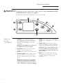 6
6
-
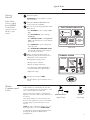 7
7
-
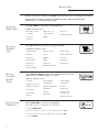 8
8
-
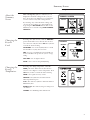 9
9
-
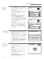 10
10
-
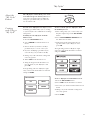 11
11
-
 12
12
-
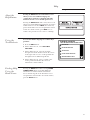 13
13
-
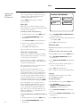 14
14
-
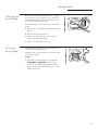 15
15
-
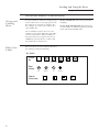 16
16
-
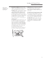 17
17
-
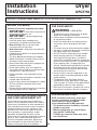 18
18
-
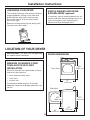 19
19
-
 20
20
-
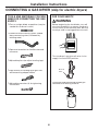 21
21
-
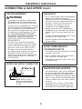 22
22
-
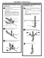 23
23
-
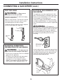 24
24
-
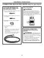 25
25
-
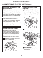 26
26
-
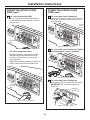 27
27
-
 28
28
-
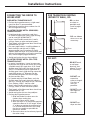 29
29
-
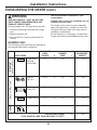 30
30
-
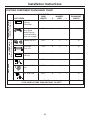 31
31
-
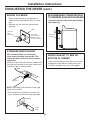 32
32
-
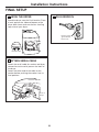 33
33
-
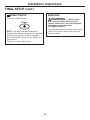 34
34
-
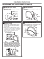 35
35
-
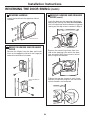 36
36
-
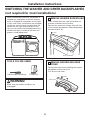 37
37
-
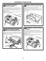 38
38
-
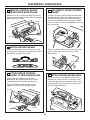 39
39
-
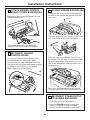 40
40
-
 41
41
-
 42
42
-
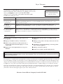 43
43
-
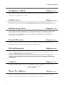 44
44
-
 45
45
-
 46
46
-
 47
47
-
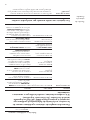 48
48
-
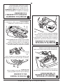 49
49
-
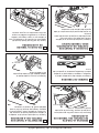 50
50
-
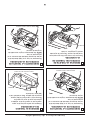 51
51
-
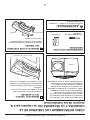 52
52
-
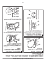 53
53
-
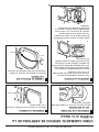 54
54
-
 55
55
-
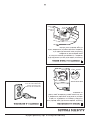 56
56
-
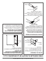 57
57
-
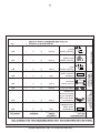 58
58
-
 59
59
-
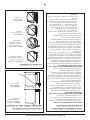 60
60
-
 61
61
-
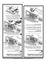 62
62
-
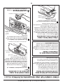 63
63
-
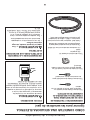 64
64
-
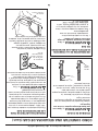 65
65
-
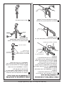 66
66
-
 67
67
-
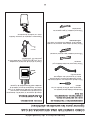 68
68
-
 69
69
-
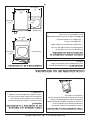 70
70
-
 71
71
-
 72
72
-
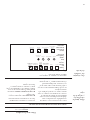 73
73
-
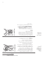 74
74
-
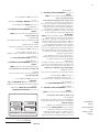 75
75
-
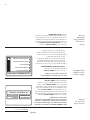 76
76
-
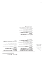 77
77
-
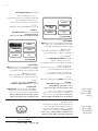 78
78
-
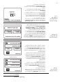 79
79
-
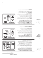 80
80
-
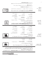 81
81
-
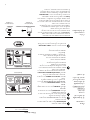 82
82
-
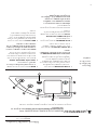 83
83
-
 84
84
-
 85
85
-
 86
86
-
 87
87
-
 88
88


GE Profile DPGT750GCWW El manual del propietario
- Tipo
- El manual del propietario
- Este manual también es adecuado para
en otros idiomas
Otros documentos
-
GE DSXH47GGWW Manual de usuario
-
-
-
GE GTD86GSSJWS El manual del propietario
-
GE GTDL740GDWW El manual del propietario
-
-
GE GTD75ECSLWS El manual del propietario
-
GE Appliances GTD84GCSNWS El manual del propietario
-
Everbilt DC4HD6 Guía de instalación