Alamo Industrial Samurai Manual de usuario
- Categoría
- Cortadoras de césped
- Tipo
- Manual de usuario

©2019 Alamo Group Inc.
Published 04/19 Part NO. 02986950C
OPERATOR’S MANUAL
ALAMO INDUSTRIAL
®
1502 E. Walnut
Seguin, Texas 78155
830-372-3551
Email: [email protected]
This Operator's Manual is an integral
part of the safe operation of this
machine and must be maintained with
the unit at all times. READ,
UNDERSTAND, and FOLLOW the
Safety and Operation Instructions
contained in this manual before
operating the equipment. C01-
Cover_AB
Important Operating and
Safety Instructions are
found in the Boom Mower
Safety Video that can be
instantly accessed on the
internet at:
www.algqr.com/abv
$0.00
BOOM ARM MOWER


In order to reduce accidents and enhance the safe operation of mowers, Alamo Industrial, in cooperation with other
industry manufacturers has developed the AEM/FEMA Industrial and Agricultural Mower Safety Practices video
and guide book.
The video will familiarize and instruct mower-tractor operators in safe practices when using industrial and
agricultural mowing equipment. It is important that Every Mower Operator
be educated in the operation of their
mowing equipment and be able to recognize the potential hazards that can occur while operating a mower. This
video, along with the mower operator’s manual and the warning messages on the mower, will significantly assist in
this important education.
Your Authorized Alamo Industrial Dealer may have shown this video and presented you a DVD Video when you
purchased your mower. If you or any mower operator have not seen this video, Watch the Video, Read this
Operator’s Manual, and Complete the Video Guidebook before operating your new mower. If you do not
understand any of the instructions included in the video or operator’s manual or if you have any questions
concerning safety of operation, contact your supervisor, dealer or Alamo Industrial.
If you would like a VHS video tape of the video, please email AEMVideo@alamo-group.com or Fax AEM VHS
Video at (830) 372-9529 or mail in a completed copy of the form on the back of this page to AEM VHS Video 1502
E Walnut Street, Seguin, TX 78155. and request the VHS video version. Please include your name, mailing
address, mower model and serial number.
Every operator should be trained for each price of equipment (Tractor and Mower), Understand the intended use,
and the potential hazards before operating the equipment.
The information and material listed above along with this Operator’s Manual can assist you in meeting the OSHA
requirement for Operator annual training.
OSHA TRAINING REQUIREMENTS
The following training requirements have been taken from Title 29, Code of Federal Regulations Part
1928.57 (a)(6). www.osha.gov
Operator Instructions. At the time of initial assignment and at least annually thereafter, the employer shall instruct
every employee who operates an agricultural tractor or implement in the safe operating practices and servicing of
equipment with which they are or will be involved, and of any other practices dictated by the work environment.

Alamo Industrial Division is willing to provide
one (1) AEM Mower Safety Practices Video
Please Send Me: VHS Format – AEM/FEMA Mower Operator Safety Video
DVD Format – AEM/FEMA Mower Operator Safety Video
Mower Operator’s Manual
AEM Mower Operator’s Safety Manual
Requester Name Phone:
Requester Address:
City
State
Zip Code
Mower Model: Serial Number:
Date Purchased: Dealer Salesperson:
Dealership Name: Dealership Location:
Mail to:
AEM Video Services
1502 E. Walnut Street
Seguin, TX 78155
Or Fax to:
(830) 372-9529
Or Email to:

To the Owner/Operator/Dealer
This Operator's Manual is an integral part of the safe operation of this machine and must be maintained with the
implement at all times. A Manual canister is provided on the implement where this manual can be properly stored.
If you lose or damage this manual a free replacement manual can be obtained from an authorized Alamo Industrial
dealer or by down loading the manual from the Alamo Industrial website www.www.alamo-industrial.com
BEFORE YOU START!! READ, UNDERSTAND, and FOLLOW the information provided in this manual, the AEM
Mower Safety manual and the tractor operator's manual carefully to learn how to operate and service your machine
properly. Failure to do so could result in personal injury to you and bystanders. All implements with moving parts
are potentially hazardous. Every effort has been made to ensure that the machine is safe but operators must avoid
engaging in unsafe practices and follow the written instructions provided. The manufacturer has designed this
implement to be used with all its safety equipment properly attached to minimize the chance of accidents.
SAFETY FIRST. Completely read and understand the safety section of this manual before operating this
equipment. Do not allow anyone to operate this equipment who has not fully read and understood this manual.
Contact your Dealer to explain any instructions that you do not fully understand.
The care you give your Alamo Industrial Implement will greatly determine your satisfaction with its performance and
its service life. Carefully read and follow the instructions in this manual to provide you with a thorough
understanding of your new implement and its intended use and service requirements.
All references made in this manual to right, left, front, rear, top or bottom are as viewed facing the direction of
forward travel with the implement properly attached to the tractor.
Replacement Parts information is located in a separate Parts Manual. Alamo Industrial mowers use balanced and
matched system components for blade carriers, blades, cuttershafts, knives, knife hangers, rollers, drivetrain
components, and bearings. These parts are made and tested to Alamo Industrial specifications. Non-genuine "will
fit" parts do not consistently meet these specifications. The use of "will fit" parts may reduce mower performance,
void warranties, and present a safety hazard. Use genuine Alamo Industrial mower parts for economy and safety.
For future reference, record your Alamo Industrial product model number and serial number.
Dealer Telephone Model Number
Owner Purchase Date: Serial Number
Serial No. Plate

DEALER to CUSTOMER Pre-Delivery/ Operation Instructions
Dealer should inform the Purchaser of this product of Warranty terms, provisions, and procedures that are
applicable. Dealer should inform Purchaser to review the contents of the Operator’s Manual including safety
equipment, safe operation and maintenance, to review the Safety Signs on the implement (and tractor if possible)
and of Purchaser’s responsibility to train his/her operators’s of safe operation procedures.
• IMPLEMENTS: I have explained that Deflectors, Chain Guards, or Solid Skirts must be installed and main-
tained in good repair.
• DRIVELINES: I have made certain that all driveline, gearbox, and other shields are in good repair and fas-
tened securely in place to prevent injuries from entanglement or thrown objects.
• HYDRAULIC MACHINES: I have explained the necessity of using clean hydraulic oil, changing filters as
instructed, stopping leaks, damage caused by operating with over-heated oil, caring for hoses, using hoses of
proper rating, maintaining the specified operating pressure and the potential hazard of oils penetrating the
skin.
• FOLDING-TYPE IMPLEMENTS: I have explained that it is not possible to guard against thrown objects when
the head is lifted off ground and that operator is responsible to watch out for persons in the area. I have
explained that the lifted mower head or boom can contact overhead obstructions with damage to cables and
telephone lines and possible injury. I have explained that the extended head or boom or retracted boom can
contact power lines resulting in electrocution, injury or death and that operator is responsible for keeping clear
of such hazards.
PRE-DELIVERY SERVICE
CHECK AND ADJUST OR LUBRICATE AS REQUIRED
See Operator’s Manual for Details
Inspection Performed - Warranty and Safety Procedures Explained - Installation Complete
LUBRICATION & HYDRAULICS
Gearbox (Oil Levels)
Hydraulic Oil Level (External Tank)
Tractor Hydraulic Oil Level
Hydraulic Hoses (Not Kinked Tighten Connections)
Front Pump Drive (Assembly Is Tight And Shaft Properly
Aligned)
MOWER
Spindle And Motor Bolts Properly Torqued
Spindle Oil Level
Blade Carrier Bolts Properly Torqued/Retaining Pin In
Place
Mower Cutting Height And Level Adjusted
Cutting Shaft Bearings Lubricated
All Hardware Properly Torqued
Tire and Air Pressure/Lug Nuts (Correct Torque)
Wheel Bearings (Check, Grease, and Preload)
ATTACHMENTS & INSTALLATION
Deflectors Front And Rear
Shredding Attachments
Correct Blade Rotation Direction
Axle Arms And Beams
Tongue And Control Rods (Installed And Adjusted)
All Bolts - Pins And Nuts (Proper Torque)
MOWER TO TRACTOR CONNECTIONS
Draw Bar Length (Check And Set)
A-Frame Pivot & Links
Control Rods (Adjusted Equal)
Axle Height (Adjusted)
Cutting Height (Adjust)
Mount Kit-Pre-Operation Check Complete
Mower Wing (Adjust Level With The Center)
Mower Wing (Check For Proper Raising Operation)
C.V. Drivelines (Check Max Turn Radius)
Pull Type Hitch (Height Adjustment)
Mounting Hardware Properly Torqued
SAFETY ITEMS
Protective Shields (Operation And Installation)
Driveline Clutch (Torque Limiter) (Adjust And Run In)
Safety Decals (Installed)
Operator’s Manual (Supplied)
Tractor PTO Shield (Installed)
S.M.V. Emblem (Installed If Needed)
Tongue Jack (Installation and Operation)
Safety Tow Chain (Installed)
ADMA Driveline Safety Manual Supplied
AEM Mower Safety Manual (Supplied in Canister)
AEM Mower Safety Video has been shown to Purchaser

Table Of Contents
SAFETY SECTION .............................................................................................................. 1-1
GENERAL SAFETY INSTRUCTIONS AND PRACTICES ................................................................................. 1-2
Operator Safety .................................................................................................................................................. 1-3
CRUSHING HAZARDS ...................................................................................................................................... 1-4
CONNECTING OR DISCONNECTING IMPLEMENT SAFETY ........................................................................ 1-5
THROWN OBJECTS HAZARDS ....................................................................................................................... 1-6
THROWN OBJECTS HAZARDS (Continued) ................................................................................................... 1-7
PTO ENTANGLEMENT HAZARDS ................................................................................................................... 1-9
MOWER BLADE CONTACT HAZARDS ......................................................................................................... 1-10
HIGH PRESSURE OIL LEAK HAZARD .......................................................................................................... 1-11
ELECTRICAL & FIRE HAZARDS .................................................................................................................... 1-12
TRANSPORTING HAZARDS .......................................................................................................................... 1-13
HAZARDS WITH MAINTENANCE OF IMPLEMENT ...................................................................................... 1-14
PARTS INFORMATION ................................................................................................................................... 1-15
Decal Location ................................................................................................................................................. 1-15
Decal Description ............................................................................................................................................. 1-25
Federal Laws and Regulations ........................................................................................................................ 1-36
INTRODUCTION SECTION ................................................................................................ 2-1
Features ............................................................................................................................................................. 2-3
OPERATION SECTION ....................................................................................................... 3-1
OPERATOR REQUIREMENTS ......................................................................................................................... 3-3
TRACTOR REQUIREMENTS ............................................................................................................................ 3-4
ROPS and Seat Belt .......................................................................................................................................... 3-4
Operator Thrown Object Protection ................................................................................................................... 3-4
Tractor Lighting and SMV Emblem .................................................................................................................... 3-5
Tractor Ballast .................................................................................................................................................... 3-5
GETTING ON AND OFF THE TRACTOR ......................................................................................................... 3-6
Boarding the Tractor .......................................................................................................................................... 3-6
Dismounting the Tractor ..................................................................................................................................... 3-7
STARTING THE TRACTOR .............................................................................................................................. 3-7
CONNECTING ATTACHING HEADS TO THE BOOM ..................................................................................... 3-8
Connecting Mower Head Hydraulics .................................................................................................................. 3-8
PRE-OPERATION INSPECTION AND SERVICE ............................................................................................. 3-9
Tractor Pre-Operation Inspection/Service ........................................................................................................ 3-10
Boom Unit Pre-Operation Inspection and Service ........................................................................................... 3-10
Cutting Component Inspection ......................................................................................................................... 3-20
Blade Bolt Inspection ....................................................................................................................................... 3-21
OPERATING THE BOOM JOYSTICK CONTROL .......................................................................................... 3-22
Mower Head Power ......................................................................................................................................... 3-23
Swing ............................................................................................................................................................... 3-24
Lift .................................................................................................................................................................... 3-25
Dipper .............................................................................................................................................................. 3-26
Tilt .................................................................................................................................................................... 3-27
Door Rotary Mower ......................................................................................................................................... 3-28
DRIVING THE TRACTOR AND IMPLEMENT ................................................................................................. 3-29
Starting the Tractor .......................................................................................................................................... 3-30
Brake and Differential Lock Setting .................................................................................................................. 3-31

Rear-Mounted Fan/Cooler Assembly ONLY on Machines Equipped (Optional) ............................................. 3-31
Driving the Tractor and Boom .......................................................................................................................... 3-32
OPERATING THE BOOM UNIT AND ATTACHED HEAD .............................................................................. 3-33
Foreign Debris Hazards/Overhead Obstructions ............................................................................................. 3-34
Operating Speed and Ground Speed .............................................................................................................. 3-35
Operating the Attached Mower Heads ............................................................................................................. 3-35
Operational Instruction ..................................................................................................................................... 3-36
Shutting Down the Attached Head ................................................................................................................... 3-41
Shutting Down the Attached Head - For (Optional Equipment) ....................................................................... 3-42
TRACTOR, BOOM, AND ATTACHED HEAD STORAGE ............................................................................... 3-43
TRANSPORTING THE TRACTOR AND IMPLEMENT ................................................................................... 3-43
Placing Boom Arm on Boom Arm Rest ............................................................................................................ 3-44
Transporting on Public Roadways ................................................................................................................... 3-45
Hauling the Tractor and Implement .................................................................................................................. 3-48
TROUBLESHOOTING GUIDE ........................................................................................................................ 3-49
MAINTENANCE SECTION .................................................................................................. 4-1
HAZARDS WITH MAINTENANCE OF IMPLEMENT ........................................................................................ 4-2
PARTS INFORMATION ..................................................................................................................................... 4-3
Lubrication Information ...................................................................................................................................... 4-3
Hydraulic Fluid ................................................................................................................................................... 4-5
Proper Oil Level ................................................................................................................................................. 4-6
Blades ................................................................................................................................................................ 4-7
Hardware ........................................................................................................................................................... 4-8
Cylinder Rod Maintenance ................................................................................................................................. 4-8
Boom Cylinder Removal and Replacement Instructions .................................................................................... 4-9
Hydraulic Component Maintenance Schedule ................................................................................................. 4-10
LEXAN Sheet Cleaning Recommendations ..................................................................................................... 4-10
Cleaning Procedure for Small Areas - Manual ................................................................................................. 4-10
Cleaning Procedure for Large Areas - Automated ........................................................................................... 4-10
Other Important Instructions for All Lexan Sheets: .......................................................................................... 4-11
Additional Important Considerations for Multiwall, Corrugated and Sign Sheet .............................................. 4-11
Graffiti removal from Lexan* Margard* sheet ................................................................................................... 4-11
Proper Torque for Fasteners ............................................................................................................................ 4-11
Service of Spindle Housing .............................................................................................................................. 4-13
ASSEMBLY ...................................................................................................................................................... 4-14
ROLLER BEARING REPLACEMENT ............................................................................................................. 4-15
TIMBER CAT HEAD ........................................................................................................................................ 4-16
Saw Blade Head .............................................................................................................................................. 4-17
Flail Mower ....................................................................................................................................................... 4-19
Flail Blades Inspection ..................................................................................................................................... 4-20
Blade Pins and D-Ring Inspection ................................................................................................................... 4-21
Flail Axe Blades Inspection .............................................................................................................................. 4-22
Flail Axe Blade Bolt Inspection ........................................................................................................................ 4-23
Grass Flail Head .............................................................................................................................................. 4-24
General Information on Flail Mower Vibration .................................................................................................. 4-26
Start up Procedure ........................................................................................................................................... 4-27
SPINDLE SERVICE PROCEDURE 02960553B and 02960553C ................................................................... 4-28
CLEANING ....................................................................................................................................................... 4-29
INSPECTION ................................................................................................................................................... 4-29
ASSEMBLY ......................................................................................................................
................................ 4-29

Safety Section 1-1
© 2019 Alamo Group Inc.
SAFETY SECTION

SAFETY
Samurai 04-19 Safety Section 1-2
© 2019 Alamo Group Inc.
SAFETY
GENERAL SAFETY INSTRUCTIONS AND PRACTICES
A careful operator is the best operator. Safety is of primary importance to the manufacturer and should be to
the owner/operator. Most accidents can be avoided by being aware of your equipment, your surroundings,
and observing certain precautions. The first section of this manual includes a list of Safety Messages that, if
followed, will help protect the operator and bystanders from injury or death. Read and understand these
Safety Messages before assembling, operating or servicing this implement. This equipment should only be
operated by those persons who have read the manual, who are responsible and trained, and who know how
to do so responsibly.
The Safety Alert Symbol combined with a Signal Word, as seen below, is used throughout this
manual and on decals which are attached to the equipment. The Safety Alert Symbol means:
“ATTENTION! BECOME ALERT! YOUR SAFETY IS INVOLVED!” The Symbol and Signal Word
are intended to warn the owner/operator of impending hazards and the degree of possible injury
faced when operating this equipment.
Indicates an imminently hazardous situation that, if not avoided, WILL result in DEATH OR
VERY SERIOUS INJURY.
Indicates an imminently hazardous situation that, if not avoided, COULD result in DEATH
OR SERIOUS INJURY.
Indicates an imminently hazardous situation that, if not avoided, MAY result in MINOR
INJURY.
Identifies special instructions or procedures that, if not strictly observed, could result in
damage to, or destruction of the machine, attachments or the environment.
NOTE: Identifies points of particular interest for more efficient and convenient operation or repair.
READ, UNDERSTAND, and FOLLOW the following Safety Messages. Serious injury or
death may occur unless care is taken to follow the warnings and instructions stated in this
Manual and in the Safety Messages on the implement. Always follow the instruction in this
manual and use good common sense to avoid hazards.
Pictographs are used throughout this manual to help bring your visual attention to safety issues.
NOTE: If you want a translation of this safety section in one of the following Languages, please contact:
Translations at 1502 E. Walnut Street Seguin, TX 78155; Fax: (830) 372-9529; Safety Section Translations
are available in Spanish, Portuguese, French, German, Russian.
PN GS01
Practice all usual and customary safe working precautions and above all---
remember safety is up to YOU
. Only YOU can prevent serious injury or death
from unsafe practices.

SAFETY
Samurai 04-19 Safety Section 1-3
© 2019 Alamo Group Inc.
SAFETY
Operator Safety
TO AVOID SERIOUS INJURY OR DEATH DO THE FOLLOWING:
• READ, UNDERSTAND and FOLLOW Operator's Manual instructions, Warnings and Safety Messages.
• WEAR SAFETY GLASSES, safety shoes, hard hat, hearing protection and gloves when operating or repairing equipment
• WEAR appropriate breathing respirator when operating in dusty conditions to avoid respiratory diseases.
• DO NOT WEAR loose clothing or jewelry to avoid rotating parts entanglement injury.
• DO NOT USE DRUGS or ALCOHOL before or while operating equipment.
• DO NOT ALLOW anyone to operate equipment under the influence of drug or alcohol.
• CONSULT medical professional for medication impairment side effects.
• STAY CLEAR of hot surfaces such as Mufflers, hydraulic pumps, valves and tanks.
• STAY ALERT, prolonged operation can cause fatigue, STOP and REST.
GENERAL OPERATING SAFETY
VISIBILITY CONDITIONS WHEN MOWING:
• OPERATE IN DAYLIGHT or with lights that gives at least 100 yards clear visibility.
• BE ABLE TO SEE and identify passersby, steep slopes, ditches, drop-offs, overhead obstructions, power lines, debris and foreign
objects.
• Avoid backing up while mowing, vision may be limited, severe damage or injury can occur.
• DO NOT run tractor in enclosed building without adequate exhaust ventilation.
GROUND SPEED WHEN MOWING:
• NORMAL SPEED range is between 1 to 2 mph(1-3 kph).
• ADJUST MOWING SPEED for terrain conditions and grass type, density and cut height.
• REDUCE MOWING SPEED when near steep slopes, ditches, drop-offs, overhead obstructions, power lines and to avoid debris
and foreign objects.
TRACTOR and MOWER
• DO NOT operate the tractor or mower unless the equipment is maintained and operating properly.
• DISCONTINUE OPERATION if tractor or mower electrical and hydraulic controls do no function properly.
• DISCONTINUE OPERATION of the tractor if the braking or steering systems do not function properly.
• DO NOT operate the tractor or mower if there are any hydraulic leaks.
INSECT INFESTATION
• DO NOT operate in areas where bees or insects may attack unless you WEAR PROTECTIVE CLOTHING or use enclosed tractor
cab.
PTO SPEED:
• DO NOT EXCEED IMPLEMENT RATED PTO SPEED
• AVOID exceeding rated PTO speeds that may result in broken drivelines or blade failures.
SAFETY SIGNS:
• REPLACE missing, damaged or unreadable safety signs immediately.
PN OSBM-01

SAFETY
Samurai 04-19 Safety Section 1-4
© 2019 Alamo Group Inc.
SAFETY
CRUSHING HAZARDS
TO AVOID SERIOUS INJURY OR DEATH FROM FALLING OFF TRACTOR, EQUIPMENT RUN OVER,
ROLLOVER AND CRUSHING BY FALLING WING OR IMPLEMENT:
• USE ROPS and SEAT BELT equipped tractors for mowing operations.
• KEEP ROPS lock in up position.
• ALWAYS BUCKLE UP seat belt when operating tractor and equipment.
• ONLY OPERATE tractor and equipment while seated in tractor seat.
WHEN RAISING BOOM MOWER:
•Raise or lower ONLY WHILE SEATED in tractor seat with seat belt buckled.
• KEEP BYSTANDERS CLEAR of area TO AVOID crushing.
• KEEP sufficient clearance around implement and wings TO AVOID contacting buildings or overhead power lines.
LIFTED Equipment can fall from mechanical or hydraulic failure or inadvertent Control Lever movement.
TO AVOID EQUIPMENT FALLING while working near or under lifted boom, components and
Mower Head:
• SECURELY SUPPORT or block up raised equipment, wings and components.
• BLOCK UP and securely support equipment before putting hands, feet or body under raised equipment or lifted compo-
nents.
• KEEP BYSTANDERS CLEAR of raised boom or mower head until securely blocked up.
WHEN PARKING Implement and Tractor:
• LOWER Mower Head to the ground or BLOCK lifted parts before leaving equipment.
• NEVER leave implement unattended in a raised position.
TO AVOID CHILDREN FALLING OFF OR BEING CRUSHED BY EQUIPMENT:
• NEVER ALLOW children to play on or around Tractor or Implement.
• DO NOT operate without operator CAB or OVERHEAD protection. Falling limbs and debris can cause injuries.
PN CHBM-01

SAFETY
Samurai 04-19 Safety Section 1-5
© 2019 Alamo Group Inc.
SAFETY
CONNECTING OR DISCONNECTING IMPLEMENT SAFETY
TO AVOID SERIOUS INJURY OR DEATH FROM BEING CRUSHED BY TRACTOR OR
IMPLEMENT:
WHEN connecting mower head to the boom
:
• KEEP BYSTANDERS AWAY from tractor and mower.
• Ensure there is enough room to lift and swing the boom with out hitting objects
BEFORE
connecting and disconnecting the mower head or boom:
• STOP TRACTOR ENGINE, place transmission into park, engage parking brake and remove key.
WHEN connecting and disconnecting the mower head or boom:
• DO NOT crawl or walk under raised mower head or boom. (Refer to Instructions in Operation Section)
WHEN CONNECTING IMPLEMENT DRIVELINE:(If equipped)
TO AVOID
implement driveline coming loose during operation:
• LUBRICATE yoke spring locking collar to ensure it freely slides on PTO shaft.
• SECURELY seat yoke locking balls in PTO shaft groove.
• PUSH and PULL DRIVELINE on both the tractor and implement PTO SHAFTS to ensure it is SECURELY
ATTACHED.
TO AVOID
broken driveline during operations:
• CHECK driveline for proper length between PTO shaft and implement gearbox shaft.(Refer to Instructions in Operation
Section)
• Drivelines too short can pull apart or disengage.
• Drivelines too long can bottom out.
• Bottoming driveline telescoping assembly will stop sliding and become solid.
• Driveline bottoming can push through support bearings and break off PTO shaft.
CONTACT DEALER
if implement driveline does not match Tractor PTO shaft:
• DO NOT USE PTO ADAPTER.
Using a PTO adapter can cause:
• Excessive vibration, thrown objects, blade and implement failures by doubling operating speed.
• Increased working length exposing unshielded driveline areas and entanglement hazards.
PN CDBM-01

SAFETY
Samurai 04-19 Safety Section 1-6
© 2019 Alamo Group Inc.
SAFETY
THROWN OBJECTS HAZARDS
ROTARY MOWERS CAN THROW OBJECTS 300 FEET OR MORE UNDER ADVERSE
CONDITIONS.
TO AVOID SERIOUS INJURY OR DEATH TO OPERATOR OR BYSTANDERS FROM THROWN OBJECTS:
• KEEP bystanders 300 feet away
STOP MOWING IF PASSERSBY ARE WITHIN 300 FEET UNLESS:
• All THROWN OBJECT SHIELDING including, Front and Rear Deflectors, Chains Guards, Steel Guards, Bands,
Side Skirts and Skid Shoes in place and in good condition when mowing.
• Mower is close and parallel to ground without exposing blades.
• MOWING AREA has been inspected and foreign materials and debris have been removed.
• DO NOT shred or mow loose or previously cut material if BYSTANDERS are within 300 feet.
• PASSERSBY are inside enclosed vehicle.
INSPECT AREA FOR POTENTIAL THROWN OBJECTS BEFORE MOWING:
• REMOVE debris, rocks, wire, cable, metal objects and other foreign material from area.
Wire, cable, rope, chains and metal objects can be thrown or swing outside deck with great velocity.
DO NOT allow the mower blades to contact decaying animal carcasses or other hazardous materials. The mower
blades could throw hazardous and biologic material out from under mower exposing the operator and bystanders to
health risks. Always wear required OSHA approved Personal Protective Equipment (PPE) when cleaning or
removing potentially hazardous material from equipment.
1. MARK objects that cannot be removed.
2. AVOID these objects when mowing.
HIGH GRASS and WEED AREA INSPECTION:
• INSPECT for and REMOVE any hidden large debris.
• MOW at Intermediate height.
• INSPECT and remove remaining debris.
• MOW at final height.
MOWER THROWN OBJECT SHIELDING:
• KEEP all thrown object shielding including, Front and Rear Deflectors, Chains Guards, Steel Guards, Bands, Side
Skirts and Skid Shoes in place and in good condition when mowing.
• DO NOT OPERATE with any thrown object shielding missing, damaged or removed.
RIGHT OF WAY (Highway) MOWING
• Stop mowing if any bystander comes within 300 feet of the mower.
• No shielding is 100% effective in preventing thrown objects. To Reduce Possibility of Injury:
1. MAINTAIN MOWER SHIELDING, side skirts, skid shoes, and blades in good operational condition,
2. RAISE CUTTING HEIGHT to 6 INCHES minimum,
3. INSPECT AREA thoroughly before mowing to REMOVE potential THROWN OBJECT HAZARDS.
4. NEVER ALLOW BLADES to CONTACT SOLID OBJECTS like wire, rocks, post, curbs, guardrails, or ground
while mowing.
PN TOBM-01

SAFETY
Samurai 04-19 Safety Section 1-7
© 2019 Alamo Group Inc.
SAFETY
THROWN OBJECTS HAZARDS (Continued)
MOWER OPERATION:
• DO NOT exceed mower's rated Cutting Capacity or cut non-vegetative material.
• USE ENCLOSED TRACTOR CABS when two or more mowers are operating in mowing area.
• Do Not mow in areas where bees or insects may attack unless you WEAR PROTECTIVE CLOTHING or
use enclosed tractor cab.
• ADJUST mower head close and parallel to ground without exposing blades.
• ADJUST cutting HEIGHT to AVOID BLADE CONTACT with solid objects like wire, rocks, posts, curbs,
guard rails and fixed obstructions.
• CLOSE Mower door and stop operating if bystanders come within 300 feet of the mower.
• Keep mower door closed when cutting close to the ground.
• Open door only to cut large brush or tree limbs. Close door immediately after cutting limb.
• DO NOT push mower head down onto material to cut it, use the front tips of the mower blades to cut into
the material.
• DO NOT operate mower when mower is in transport position.
• STOP MOWING immediately if blades strike heavy objects, fixed structures, metal guard rails and
concrete structures:
1. BLADES CAN FAIL from impact and objects can be thrown with great velocity.
2. INSPECT and REPLACE any damaged blades.
3. CHECK blade carrier and REPLACE if damaged.
• DO NOT mow in standing water TO AVOID possible BLADE FAILURE.
• AVOID MOWING in reverse:
1. STOP PTO and back up mower.
2. LOWER mower, engage PTO and mow forward.
• DISENGAGE mower head and wait until BLADES stop rotating before raising mower to transport
position.
• DO NOT ENGAGE PTO with mower in transport position.
• STOP mowing when EXCESSIVE VIBRATION occurs:
1. STOP PTO and tractor ENGINE.
2. INSPECT mower for vibration source.
3. REPLACE any damaged parts and bent or damaged BLADES.
PN TOBM-02

SAFETY
Samurai 04-19 Safety Section 1-8
© 2019 Alamo Group Inc.
SAFETY
RUN OVER HAZARDS
TO AVOID SERIOUS INJURY OR DEATH FROM FALLING OFF TRACTOR OR
EQUIPMENT RUN OVER:
• USE ROPS and SEAT BELT equipped tractors for mowing operations.
• KEEP ROPS locked in UP position.
• ONLY start tractor while seated in tractor seat.
• ALWAYS BUCKLE UP seat belt when operating tractor and equipment.
• ONLY OPERATE tractor and equipment while seated in tractor seat.
• NEVER ALLOW RIDERS on tractor or implement.
• When not mowing stow Boom and Mower head in transport location before moving.
WHEN MOUNTING AND DISMOUNTING TRACTOR:
• ONLY mount or dismount when tractor and moving parts are stopped.
• STOP ENGINE AND PTO, engage parking brake, lower implement, allow all moving parts to stop and
remove key before dismounting from tractor.
PN ROBM-01

SAFETY
Samurai 04-19 Safety Section 1-9
© 2019 Alamo Group Inc.
SAFETY
PTO ENTANGLEMENT HAZARDS
KEEP AWAY FROM ROTATING DRIVELINES AND ELEMENTS TO AVOID SERIOUS INJURY OR
DEATH:
STAY AWAY
and KEEP hands, feet and body AWAY from rotating blades, drivelines and parts until all moving
elements have stopped.
• STOP, LOOK and LISTEN before approaching the mower to make sure all rotating motion has stopped.
• ROTATING COMPONENTS CONTINUE to ROTATE after the PTO is shut off.
PTO SHIELDING:
TO AVOID SERIOUS INJURY OR DEATH FROM ENTANGLEMENT WHEN OPERATING IMPLEMENT:
• KEEP PTO shields, integral driveline shields and input shields installed
• DO NOT OPERATE mower without shields and guards in place or missing
• REPAIR OR REPLACE if damage, broken or missing
• ALWAYS REPLACE GUARDS that have been removed for service or maintenance.
• Do Not use PTO or PTO guard as a step.
TO AVOID
broken driveline during operations:
• CHECK driveline for proper length between PTO shaft and implement gearbox shaft.(Refer to Instructions in
Operation Section)
• Drivelines too short can pull apart or disengage.
• Drivelines too long can bottom out.
Bottoming driveline telescoping assembly will stop sliding and become solid.
• Driveline bottoming can push through support bearings and break off PTO shaft
• AVOID sharp turns or lift mower to heights to cause driveline "knocking".
• Lubricate driveshaft-telescoping components weekly.
CONTACT DEALER
if implement driveline does not match Tractor PTO shaft:
• DO NOT USE PTO ADAPTER.
Using a PTO adapter can cause excessive vibration, thrown objects, blade and implement failures by
doubling operating speed. Increased working length exposing unshielded driveline areas.
PN PE01

SAFETY
Samurai 04-19 Safety Section 1-10
© 2019 Alamo Group Inc.
SAFETY
MOWER BLADE CONTACT HAZARDS
KEEP AWAY FROM ROTATING BLADES TO AVOID SERIOUS INJURY OR DEATH FROM
BLADE CONTACT:
• STAY AWAY and KEEP HANDS, FEET and BODY AWAY from rotating blades, drivelines and parts until all moving
elements have stopped.
• DO NOT put hands or feet under mower decks
• STOP rotating BLADES disengage mower switch and PTO and wait for blade to stop rotating before raising mower
head.
• DO NOT approach Sickle Bar head until Tractor Engine has been shut off.
• STOP LOOK and LISTEN before approaching the mower to make sure all rotating motion has stopped.
PN MBBM-01

SAFETY
Samurai 04-19 Safety Section 1-11
© 2019 Alamo Group Inc.
SAFETY
HIGH PRESSURE OIL LEAK HAZARD
TO AVOID SERIOUS INJURY OR DEATH FROM HIGH PRESSURE HYDRAULIC OIL LEAKS
PENETRATING SKIN:
• DO NOT OPERATE equipment with oil or fuel leaks.
• KEEP all hydraulic hoses, lines and connections in GOOD CONDITION and TIGHT before applying system
pressure.
• RELIEVE HYDRAULIC PRESSURE before disconnecting lines or working on the system.
• REMOVE and replace hose if you suspect it leaks. Have dealer test it for leaks.
HIGH PRESSURE FLUID LEAKS CAN BE INVISIBLE.
WHEN CHECKING FOR HYDRAULIC LEAKS AND WORKING AROUND HYDRAULIC SYSTEMS:
• ALWAYS WEAR safety glasses and impenetrable gloves.
• USE paper or cardboard to search for leaks.
• DO NOT USE hands or body parts to search for leak.
• KEEP hands and body AWAY from pin holes and nozzles ejecting hydraulic fluid.
• Hydraulic fluid may cause gangrene if not surgically removed immediately by a doctor familiar with this form of injury.
Use caution when removing Hydraulic Tank cap.
• Tank contents may be under pressure.
• Allow oil to cool before removing cap.
• Relieve oil pressure before removing cap slowly.
• Stay away from hot oil that may spray from tank.
PN HPBM-01

SAFETY
Samurai 04-19 Safety Section 1-12
© 2019 Alamo Group Inc.
SAFETY
ELECTRICAL & FIRE HAZARDS
TO AVOID SERIOUS INJURY OR DEATH FROM ELECTRICAL CONTACT WHEN
WORKING AROUND ELECTRICAL POWER LINES, GAS LINES AND UTILITY LINES:
• INSPECT mowing area for overhead or underground electrical power lines, obstructions, gas lines,
cables and Utility, Municipal, or other type structure.
• KEEP all raised wings at a 10 feet or greater distance from all power lines and overhead obstructions.
• DO NOT allow mower to contact with any Utility, Municipal, or type of structures and obstructions.
• CALL 811 and 1-800-258-0808 for identify buried utility lines.
FIRE PREVENTION GUIDELINES while Operating, Servicing, and Repairing Mower and Tractor to
reduce equipment and grass fire Risk:
• EQUIP Tractor with a FIRE EXTINGUISHER
• DO NOT OPERATE mower on a tractor equipped with under frame exhaust
• DO NOT SMOKE or have open flame near Mower or Tractor
• DO NOT DRIVE into burning debris or freshly burnt area
• AVOID FIRE IGNITION by not allowing mower blade to contact solid objects like metal or rock.
• DO NOT operate if oil is leaking. Repair oil leak and remove all accumulated oil before operating.
• CLEAR any grass clippings or debris buildup around mower hydraulic pumps, valves or tanks.
• SHUT OFF ENGINE while refueling.
PN EFBM-01

SAFETY
Samurai 04-19 Safety Section 1-13
© 2019 Alamo Group Inc.
SAFETY
TRANSPORTING HAZARDS
TO AVOID SERIOUS INJURY AND DEATH WHEN TOWING OR TRANSPORTING EQUIPMENT:
• KEEP transport speed BELOW 20 mph to maintain control of equipment.
• REDUCE SPEED on inclines, turns and in poor towing conditions.
• DO NOT TOW with trucks or other vehicles.
• USE only properly sized and equipped tractor for towing equipment.
• FOLLOW all local traffic regulations.
TRACTOR REQUIREMENTS FOR TOWING OR TRANSPORTING IMPLEMENTS:
• ONLY TRANSPORT with tractor with ROPS in the raised position.
• USE properly sized and equipped tractor that exceeds implement weight by at least 20%.
• KEEP 20% of tractor weight on front wheels to maintain safe steering.
BEFORE TRANSPORTING OR TOWING IMPLEMENT:
TRACTOR INSPECTION:
• CHECK steering and braking for proper operation and in good condition.
• CHECK SMV sign, reflectors and warning lights for proper operation and visibility behind unit.
• CHECK that your driving vision is not impaired by tractor, cab, or implement while seated in tractor seat.
• ADJUST your operating position, mirrors, and implement transport for clear vision for traveling and traffic conditions.
PREPARE IMPLEMENT FOR TRANSPORTING OR TOWING:
• Store Boom and Mower in transport positions and engage transport locks if equipped.
DETERMINE STOPPING CHARACTERISTICS OF TRACTOR AND IMPLEMENT FOR TRANSPORTING OR
TOWING:
BRAKING TESTS:
• Stopping distance with implement attached may increase
• Observe STOPPING distances increases with increased speeds.
• DETERMINE the maximum safe transport speed that does not exceed 20 mph.
• Reduce travel speed on wet or icy roads, stopping distances increase.
DETERMINE MAXIMUM TURNING SPEED BEFORE OPERATING ON ROADS OR UNEVEN GROUND:
• TEST equipment by slowly increasing speed in turns to determine if it can be operated at higher speeds.
• USE REDUCED turning speeds on sharp turns to avoid equipment turning over.
WHEN TOWING OR TRANSPORTING EQUIPMENT:
• Always WEAR SEAT BELT when operating or transporting mower.
• USE low speeds to avoid overturn with raised wings.
• USE low speeds and gradual steering on curves, hills, rough or uneven surfaces, and on wet roads.
• TURN ON tractor FLASHING WARNING LIGHTS.
• ALLOW clearance for implement swing while turning.
KEEP raised boom mower 10 feet or greater distance from all power lines and overhead obstructions.
PN THBM-01

SAFETY
Samurai 04-19 Safety Section 1-14
© 2019 Alamo Group Inc.
SAFETY
HAZARDS WITH MAINTENANCE OF IMPLEMENT
AVOID SERIOUS INJURY OR DEATH FROM COMPONENT FAILURE BY KEEPING IMPLEMENT IN
GOOD OPERATING CONDITION BY PERFORMING PROPER SERVICE, REPAIRS AND
MAINTENANCE.
BEFORE PERFORMING SERVICE, REPAIRS AND MAINTENANCE ON THE IMPLEMENT:
• STOP ENGINE AND PTO, engage parking brake, lower implement, allow all moving parts to stop and remove key before
dismounting from tractor.
• PLACE implement on ground or securely block up raised equipment. Use large blocks on soft or wet soil.
•
PUSH and PULL Remote Hydraulic Cylinder lever to relieve hydraulic pressure.
•
DISCONNECT Pump solenoid valve or PTO driveline connection before servicing mower head.
•
WEAR SAFETY GLASSES, PROTECTIVE GLOVES and follow SAFETY PROCEDURES when performing service, repairs
and maintenance on the implement:
•Always WEAR protective GLOVES when handling blades, knives, cutting edges or worn component with sharp edges.
•Always
WEAR GLOVES and SAFETY GLASSES when servicing hot components
•
AVOID CONTACT with hot hydraulic oil tanks, pumps, motors, valves and hose connection surfaces.
•
SECURELY support or BLOCK UP raised implement, framework and lifted components before working underneath equipment.
•
FOLLOW INSTRUCTIONS in maintenance section when replacing hydraulic cylinders to prevent component falling.
•
STOP any implement movements and SHUT-OFF TRACTOR engine before doing any work procedures.
•
USE ladder or raised stands to reach high equipment areas inaccessible from ground.
•
ENSURE good footing by standing on solid flat surfaces when getting on implement to perform work.
•
FOLLOW manufacturer's instructions in handling oils, solvents, cleansers, and other chemical agents.
•
DO NOT change any factory-set hydraulic calibrations to avoid component or equipment failures.
•
DO NOT modify or alter implement, functions or components.
•
DO NOT WELD or repair rotating mower components. These may cause vibrations and component failures being thrown from
mower.
PERFORM SERVICE, REPAIRS, LUBRICATION AND MAINTENANCE OUTLINED IN IMPLEMENT MAINTENANCE
SECTION:
• INSPECT for loose fasteners, worn or broken parts, leaky or loose fittings, missing or broken cotter keys and washers on pins, and
all moving parts for wear.
• REPLACE any worn or broken parts with authorized service parts.
• Inspect mower blade spindle to ensure bearing pre-load. If loose repair before operating.
• LUBRICATE unit as specified by lubrication schedule
•
NEVER lubricate, adjust or remove material while it is running or in motion.
•
TORQUE all bolts and nuts as specified.
BLADE INSPECTION:
• Inspect blade carrier and blades daily.
• Check blade and blade carrier BOLT TORQUE daily. Loose bolts can cause blade or blade bolt failures.
• REPLACE, bent, damage, cracked and broken blades immediately with new blades.
•
AVOID blade failures and thrown broken blades. DO NOT straighten, weld, or weld hard-facing blades.
SAFETY SHIELDS, GUARDS AND SAFETY DEVICES INSPECTION:
• KEEP all Deflectors, Chain Guards, Steel Guards, Gearbox Shields, and PTO integral shields, Bands, Side Skirts and Skid Shoes
in place and in good condition.
• REPLACE any missing, broken or worn safety shields, guards and safety devices.
Operating, servicing and maintaining this equipment can expose you to chemicals including gasoline,
diesel fuel, lubricants, petroleum products, engine exhaust, carbon monoxide, and phthalates, which are
known to the State of California to cause cancer and birth defects or other reproductive harm. To minimize
exposure, avoid breathing exhaust, do not idle the engine except as necessary, service your vehicle in a
well-ventilated area and wear gloves or wash your hands frequently when servicing your vehicle. Battery
posts, terminals and related accessories contain lead and lead compounds, chemicals known to the state
of California to cause cancer, birth defects or other reproductive harm. For more information go to
www.P65Warnings.ca.gov. This website, operated by California's Office of Environmental Health Hazard
Assessment, provides information about these chemicals and how individuals may be exposed to them.
PN HMBM-01

SAFETY
Samurai 04-19 Safety Section 1-15
© 2019 Alamo Group Inc.
SAFETY
PARTS INFORMATION
Decal Location
NOTE: Alamo Industrial supplies safety decals on this product to promote safe operation. Damage to the
decals may occur while in shipping, use, or reconditioning. Alamo Industrial cares about the safety of its
customers, operators, and bystanders, and will replace the safety decals on this product in the field, free of
charge (Some shipping and handling charges may apply). Contact your Alamo Industrial dealer to order
replacement decals.
PARTS INFORMATION
Alamo Industrial mowers use balanced and matched system components for blade carriers, blades,
cuttershafts, knives, knife hangers, rollers, drivetrain components, and bearings. These parts are made and
tested to Alamo Industrial specifications. Non-genuine "will fit" parts do not consistently meet these
specifications. The use of “will fit” parts may reduce mower performance, void mower warranties, and present
a safety hazard. Use genuine Alamo Industrial mower parts for economy and safety.
(SPAM-1)
SEE YOUR ALAMO DEALER

SAFETY
Samurai 04-19 Safety Section 1-16
© 2019 Alamo Group Inc.
SAFETY

SAFETY
Samurai 04-19 Safety Section 1-17
© 2019 Alamo Group Inc.
SAFETY
ITEM PART NO. QTY. TYPE DESCRIPTION
1. 03200347 (1) REFLECT SMV
2. D677 1 INSTRUCT Boom Mower Safety Booklet
3. D617 3 DANGER Hydraulic Oil Hazard
4. D625 1 WARNING Pressurized Tank
5. D627 1 IMPORTANT Avoid Electrical Damage
6. 02982828 1 ATTENTION Correct Hydraulic Fluid
7. 02971943 1 LOGO Alamo Industrial
8. 02987402 1 INSTRUCT Hose Connection
9. D644 1 INSTRUCT Blue Dot Decal
10. D645 1 INSTRUCT Red Dot Decal
11. D624 1 IMPORTANT Operate at 540 RPM
12. D628 1 DANGER Crushing Hazard
13. D623 1 WARNING Pinch Points
14. 1458392 2 REFLECT Red Reflector
15. 1458393 1 REFLECT Yellow Reflector
16. 002508 1 LOGO Alamo Industrial
17. D876 1 WARNING Crushing Hazard-Tire Ballast
18. D688 1 WARNING Clearance Hazard
19. D630 1 IMPORTANT Service Hydraulic Oil
20. 02988245 2 INSTRUCT Re-order OEM Parts
21. 00776031 1 -------------- Canister
22. 02986950C 1 -------------- Operator’s Manual

SAFETY
Samurai 04-19 Safety Section 1-18
© 2019 Alamo Group Inc.
SAFETY
ITEM PART NO. QTY. LEVEL DESCRIPTION
1. 00757139 2 LOGO Alamo Industrial Logo
2. D626 2 WARNING Thrown Object Hazard
3. D619 1 WARNING Blade Rotation
4. 2738332 1 REFLECT Red Reflector
5. 2738333 1 REFLECT Yellow Reflector
6. 02986112 1 SERIAL PLATE Serial Number Plate - 60” Rotary
02986679 1 SERIAL PLATE. Serial Number Plate - 50” Rotary
7. 02970889 1 LOGO 60” Rotary
02982927 1 LOGO 50” Rotary
8. D622 1 DANGER Blades, Thrown Objects
9. D620 1 WARNING Replace Blades in Pairs
10. D564 1 WARNING Use Genuine Parts
11. D718 1 INSTRUCT Lube Chart
12. D621 1 IMPORTANT Lube Spindle Every 40 hrs
13. D637 1 WARNING Disconnect Hydraulic Solenoid
14. 00757140 1 LOGO Alamo Industrial Logo

SAFETY
Samurai 04-19 Safety Section 1-19
© 2019 Alamo Group Inc.
SAFETY
ITEM PART NO. QTY. LEVEL DESCRIPTION
1. D661 1 INSTRUCT Lube Chart
2. D564 1 WARNING Use Genuine Parts
3. D622 1 DANGER Thrown Objects Safety Shields
4. D637 1 WARNING Disconnect Hydraulic Solenoid
5. D646 1 WARNING Guard Missing
6. D641 1 WARNING Belt Shield
7. 000108 1 INSTRUCT Flail Operation
8. D626 1 DANGER Thrown Object Hazard
9. 02970887 1 LOGO Flail Axe 48”
10. nfs 1 SERIAL PLATE Flail Axe Serial Number
11. 02979551 1 LOGO Alamo Industrial Logo
12. 00757139 2 LOGO Alamo Industrial

SAFETY
Samurai 04-19 Safety Section 1-20
© 2019 Alamo Group Inc.
SAFETY
ITEM PART NO. QTY. TYPE DESCRIPTION
1. D564 1 WARNING Use Genuine Parts
2. D637 1 WARNING Disconnect Hydraulic Solenoid
3. D641 1 WARNING Belt Shield
4. D646 1 WARNING Shields & Guards
5. D626 2 DANGER Thrown Object Hazard
6. D661 1 INSTRUCT Lube Chart
7. 00757139 1 LOGO Alamo Industrial Logo
8. 000108 1 INSTRUCT Flail Operation Instructions
9. nfs 1 SERIAL PLATE Flail Head Serial Plate
10. D622 1 DANGER Thrown Object Hazard
11. 1458392 1 REFLECT Red Reflector
12. 1458393 1 REFLECT Yellow Reflector
13. 02960766 1 LOGO Alamo Industrial Logo

SAFETY
Samurai 04-19 Safety Section 1-21
© 2019 Alamo Group Inc.
SAFETY
ITEM PART NO. QTY. TYPE DESCRIPTION
1. D546 1 DANGER Guard Missing
2. D637 1 WARNING Disconnect Hydraulic Solenoid
3. D564 1 WARNING Genuine Parts
4. D639 1 DANGER Amputation Hazard
5. D662 1 INSTRUCT Lubrication Decal
6. 00757139 1 LOGO Alamo Industrial Logo
7. 00757140 1 LOGO Decal - Alamo Industrial Logo
8. 02971931 1 LOGO Decal - Timber Cat

SAFETY
Samurai 04-19 Safety Section 1-22
© 2019 Alamo Group Inc.
SAFETY
ITEM PART NO. QTY. TYPE DESCRIPTION
1. D564 1 WARNING Use Genuine Parts
2. D642 1 WARNING Thrown Objects
3. D637 1 WARNING Disconnect Hydraulic Solenoid
4. D663 1 INSTRUCT Lubrication Chart
5. nfs 1 SERIAL PLATE Ditcher Serial Number Plate
6. 999204 1 LOGO Ditcher Decal
7. 002508 1 LOGO Alamo Industrial Logo
8. 02970888 1 LOGO Boom Ditcher Name Logo

SAFETY
Samurai 04-19 Safety Section 1-23
© 2019 Alamo Group Inc.
SAFETY
ITEM PART NO. QTY. TYPE DESCRIPTION
1. D660 1 INTRUCT Lube Location
2. D646 2 DANGER Guard Missing
3. D619 1 WARNING Blade Rotation
4. 02979546 1 LOGO Alamo Industrial
5. D564 1 WARNING Genuine Parts
6. D638 1 WARNING Hearing Loss
7. D641 1 WARNING Belt Shield
8. D637 1 WARNING Disconnect Hydraulic Solenoid
9. D640 1 DANGER Amputation Hazard
10. 1458392 1 REFLECT Red Reflector
11. 1458393 1 REFLECT Yellow Reflector
12. 02975516 1 INTRUCT No Hitch Post Here
13. 00757139 2 LOGO Alamo Industrial
14. nfs 1 SERIAL NUM Serial Plate
15. 02974998 1 LOGO Logo Buzzbar

SAFETY
Samurai 04-19 Safety Section 1-24
© 2019 Alamo Group Inc.
SAFETY
BATTLE AXE
ITEM PART NO. QTY. TYPE DESCRIPTION
1. D564 1 WARNING Use Genuine Parts
2. D622 1 DANGER Thrown Objects Hazard
3. 02979551 1 LOGO Alamo Industrial
4. D646 2 DANGER Guard Missing
5. D641 1 WARNING Belt Shield
6. D726 1 INSTRUCT Grease Fitting Inside
7. 226-181 4 INSTRUCT Grease Every 8 Hours
8. D637 1 WARNING Disconnect Hydraulic Solenoid
9. 000108 1 INSTRUCT Flail Operation Instructions
10. 02992908 1 LOGO Battle Axe
11. 00757139 1 LOGO Alamo Industrial
12. D626 1 DANGER Rubber Deflectors Missing
13. D950 1 INSTRUCT Lubrication Decal

SAFETY
Samurai 04-19 Safety Section 1-25
© 2019 Alamo Group Inc.
SAFETY
ITEM PART NO. QTY. TYPE DESCRIPTION
1. D623 4 WARNING Pinch Points
2. 02987466 2 NAME LOGO Samurai - 18’
02987467 2 NAME LOGO Samurai - 22’
02987468 2 NAME LOGO Samurai - 25’
3. 02981987 1 INSTRUCT Hose Connection
4. nfs 1 SERIAL PLATE Serial Number Plate
5. D835 1 DANGER Multi-Hazard/Language
6. D665 1 Instruct Lube Location - Boom

SAFETY
Samurai 04-19 Safety Section 1-26
© 2019 Alamo Group Inc.
SAFETY
Decal Description

SAFETY
Samurai 04-19 Safety Section 1-27
© 2019 Alamo Group Inc.
SAFETY

SAFETY
Samurai 04-19 Safety Section 1-28
© 2019 Alamo Group Inc.
SAFETY

SAFETY
Samurai 04-19 Safety Section 1-29
© 2019 Alamo Group Inc.
SAFETY

SAFETY
Samurai 04-19 Safety Section 1-30
© 2019 Alamo Group Inc.
SAFETY

SAFETY
Samurai 04-19 Safety Section 1-31
© 2019 Alamo Group Inc.
SAFETY

SAFETY
Samurai 04-19 Safety Section 1-32
© 2019 Alamo Group Inc.
SAFETY

SAFETY
Samurai 04-19 Safety Section 1-33
© 2019 Alamo Group Inc.
SAFETY

SAFETY
Samurai 04-19 Safety Section 1-34
© 2019 Alamo Group Inc.
SAFETY

SAFETY
Samurai 04-19 Safety Section 1-35
© 2019 Alamo Group Inc.
SAFETY

SAFETY
Samurai 04-19 Safety Section 1-36
© 2019 Alamo Group Inc.
SAFETY

SAFETY
Samurai 04-19 Safety Section 1-37
© 2019 Alamo Group Inc.
SAFETY
FEDERAL LAWS AND REGULATIONS
This section is intended to explain in broad terms the concept and effect of federal laws and regulations concerning
employer and employee equipment operators. This section is not intended as a legal interpretation of the law and
should not be considered as such.
Employer-Employee Operator Regulations
U.S. Public Law 91-596 (The Williams-Steiger Occupational and Health Act of 1970) OSHA
This Act Seeks:
“...to assure so far as possible every working man and woman in the nation safe and healthful working
conditions and to preserve our human resources...”
DUTIES
Sec. 5 (a) Each employer-
(1) shall furnish to each of his employees employment and a place of employment which are free from
recognized hazards that are causing or are likely to cause death or serious physical harm to his employees;
(2) shall comply with occupational safety and health standards promulgated under this Act.
(b) Each employee shall comply with occupational safety and health standards and all rules, regulations and
orders issued pursuant to this Act which are applicable to his own actions and conduct.
OSHA Training Requirements
Title 29, Code of Federal Regulations Part 1928.57(a)(6). www.osha.gov
Operator instructions. At the time of initial assignment and at least annually thereafter, the employer shall
instruct every employee who operates an agricultural tractor and implements in the safe operating practices
and servicing of equipment with which they are or will be involved, and of any other practices dictated by the
work environment.
Keep all guards in place when the machine is in operation;
Permit no riders on equipment
Stop engine, disconnect the power source, and wait for all machine movement to stop before servicing,
adjusting, cleaning or unclogging the equipment, except where the machine must be running to be properly
serviced or maintained, in which case the employer shall instruct employees as to all steps and procedures
which are necessary to safely service or maintain the equipment.
Make sure everyone is clear of machinery before starting the engine, engaging power, or operating the
machine.
Employer Responsibilities:
To ensure employee safety during Tractor and Implement operation, it is the employer’s responsibility to:
1. Train the employee in the proper and safe operation of the Tractor and Implement.
2. Require that the employee read and fully understand the Tractor and Implement Operator’s manual.
3. Permit only qualified and properly trained employees to operate the Tractor and Implement.
4. Maintain the Tractor and Implement in a safe operational condition and maintain all shields and guards on the
equipment.
5. Ensure the Tractor is equipped with a functional ROPS and seat belt and require that the employee operator
securely fasten the safety belt and operate with the ROPS in the raised position at all times.
6. Forbid the employee operator to carry additional riders on the Tractor or Implement.
7. Provide the required tools to maintain the Tractor and Implement in a good safe working condition and provide the
necessary support devices to secure the equipment safely while performing repairs and service.
8. Require that the employee operator stop operation if bystanders or passersby come within 300 feet.
Child Labor Under 16 Years of Age
Some regulations specify that no one under the age of 16 may operate power machinery. It is your responsibility to
know what these regulations are in your own area or situation. (Refer to U.S. Dept. of Labor, Employment Standard
Administration, Wage & Home Division, Child Labor Bulletin #102.)


2
Contents
Acknowledgment . . . . . . . . . . . . . . . . . . . . . . . . . . . . . . 2
Foreword . . . . . . . . . . . . . . . . . . . . . . . . . . . . . . . . . . . . . 2
Safety Alerts. . . . . . . . . . . . . . . . . . . . . . . . . . . . . . . . . . . 3
A Word To The User/Operator . . . . . . . . . . . . . . . . . . . . 3
The Industrial/Agricultural Mower. . . . . . . . . . . . . . . . . 4
Follow A Safety Program . . . . . . . . . . . . . . . . . . . . . . . . 5
Prepare For Safe Operation . . . . . . . . . . . . . . . . . . . . . . 9
Start Safely. . . . . . . . . . . . . . . . . . . . . . . . . . . . . . . . . . . 13
Operate Safely . . . . . . . . . . . . . . . . . . . . . . . . . . . . . . . . 13
Park Safely. . . . . . . . . . . . . . . . . . . . . . . . . . . . . . . . . . . 18
Shut Down Safely . . . . . . . . . . . . . . . . . . . . . . . . . . . . . 18
Perform Maintenance Safely . . . . . . . . . . . . . . . . . . . . 19
Final Word To The User. . . . . . . . . . . . . . . . . . . . . . . . . 26
Acknowledgment
We wish to acknowledge the contributions of the members of AEM’s Industrial/Agricultural Mower Manufacturers Council
to the preparation of this Safety Manual.
NOTICE OF COPYRIGHT PROTECTION
Copyright, 2010, by the Association of Equipment Manufacturers. All rights reserved. This work may not be reproduced or disseminated in whole or in part by any means
without the prior written permission of the Association of Equipment Manufacturers.
Copyright 2010© AEM (Association of Equipment Manufacturers)
Revised 01/03, 09/10
This safety manual is intended to point out some of the
basic safety situations that may be encountered during
the normal operation and maintenance of your machine
and to instruct you in safety practices for dealing with
these conditions. This manual is NOT a substitute for
the mower manufacturer’s operator’s manual(s).
Additional precautions may be necessary, or some
instructions may not apply, depending on equipment,
attachments and conditions at the worksite or in the
service area. The manufacturer has no direct control
over equipment application, operation, inspection or
maintenance. Therefore, it is YOUR responsibility to
use good safety practices in these areas.
The information provided in this manual supplements
the speci c information about your machine that is
contained in the manufacturer’s operator’s manual(s).
Other information that may affect the safe operation of
your machine may be contained on safety signs or in
insurance requirements, employer’s safety and training
programs, safety codes, local, state/provincial and
federal laws, rules and regulations.
IMPORTANT! Before you operate the mower,
make sure you have the manufacturer’s
operator’s manual(s) for this machine and all
attachments. If the manufacturer’s manuals
are missing, obtain replacement manuals from
your employer, equipment dealer or directly
from the manufacturer. Keep this safety manual
and the manufacturer’s manuals with the
machine at all times. Read and understand all
manuals.
The AEM Mower Safety Practices video is
available to train and reinforce good safety
practices. Operators are encouraged to
periodically view the safety video.
Foreword
Read and
Understand
Manuals Before
Operating

3
Safety Alerts
Symbol
This Safety Alert Symbol means: “ATTENTION!
STAY ALERT! YOUR SAFETY IS INVOLVED!”
The Safety Alert Symbol identi es important safety
messages on equipment, safety signs, in manuals or
elsewhere. When you see this symbol, be alert to the
possibility of death or personal injury. Follow
instructions in the safety message.
Reasons Safety is Important:
— Accidents disable and kill.
— Accidents cost.
— Accidents can be avoided.
Signal Words
Signal words are distinctive words that will typically be
found on safety signs on the mower and other worksite
equipment. These words may also be found in this
manual and the manufacturer’s manuals. These words
are intended to alert the operator to a hazard and the
degree of severity of the hazard.
DANGER indicates a hazardous
situation which, if not avoided, will
result in death or serious injury.
WARNING indicates a hazardous
situation which, if not avoided, could
result in death or serious injury.
CAUTION indicates a hazardous
situation which, if not avoided, could
result in minor or moderate injury.
NOTICE indicates a property
damage message.
DANGER
WARNING
CAUTION
NOTICE
A Word To The User/Operator
It is YOUR responsibility to read and understand the
safety manual and the manufacturer’s manuals before
operating this machine. This safety manual takes you
step by step through your working day.
Hazard Recognition and Accident Prevention depend
upon you being alert, careful and properly trained in the
operation, transport, maintenance and storage of this
equipment.
Graphics have been provided to help you understand
the text.
Remember that YOU are the key to safety. Good safety
practices not only protect you but also protect the
people around you. Study and understand this manual
and the manufacturer’s manuals for your speci c
machine. Make them a working part of your safety
program. Keep in mind that this safety manual is written
for industrial/agricultural mowers.
Contact the manufacturer of your equipment to answer
any questions about safe operation that remain after
studying the manufacturer’s operator’s manual(s) and
this safety manual.
Practice all other usual and customary safe
working precautions and above all:
REMEMBER — SAFETY IS UP TO YOU!
YOU CAN PREVENT SERIOUS INJURY OR
DEATH CAUSED BY UNSAFE WORK PRACTICES!
Read and
Understand All
Safety Signs

4
Industrial/Agricultural Mower Types
Mowers are used for pasture clipping, crop residue
shredding, heavy brush cutting, waterways, right-of-
ways, roadside or highway mowing. Also, these mowers
are used for cutting grass and other growth in public
areas such as parks and cemeteries.
The Industrial/Agricultural Mower
Sickle Bar
Flail
Rotary
Boom
Folding Wing Rotary
Agricultural Disc Mower Types
Disc mowers are designed and equipped to cut hay
crops at higher eld speed.
Disc mower/conditioners mow and condition crops.
Self-propelled windrowers mow and form conditioned
hay into windrows.
The Industrial/Agricultural Mower
Disc Mower
Disc Mower
Conditioner
Self-propelled
Windrower

5
Follow A Safety Program
Protect Yourself
Wear personal protective clothing and Personal
Protective Equipment (PPE) issued to you or called
for by job conditions. You must ALWAYS wear safety
glasses with side shields.
You may also need:
— Hard hat
— Safety shoes
— Safety goggles or face shield
— Heavy gloves
— Hearing protection
— Re ective clothing
— Wet weather gear
— Respirator or lter mask
Wear whatever is needed—don’t take chances.
WARNING! Prevent death or serious injury from
entanglement. Do not wear loose clothing or
accessories. Tie up long hair. Stay away from all
rotating components when the engine is running.
Contact, wrapping or entanglement with rotating or
moving parts could result in death or serious injury.
Avoid
Entanglement
Follow A Safety Program
— Read, understand and follow the manufacturer’s
written instructions found in the operator’s manual(s)
and safety signs on mower and tractor.
— Have operational training with mower and tractor.
— Take advantage of training programs offered in
your area.
— Ask your equipment dealer or supervisor to explain
things you do not understand.
— Explain the written instructions in the operator’s
manual(s) and safety signs to those users or
operators who cannot read.
— Inspect the mower and tractor daily before operating.
Ensure all guards are in place and the equipment is
operating properly.
— Never smoke while operating. Never ll the fuel tank
with the engine running or near an open ame.
— Make sure you have adequate visibility and suf cient
lighting.
— Know the pinch points and rotating parts. Awareness
on your part can prevent accidents.
— Never attempt to operate the controls except from
the operator’s seat. Improperly controlled functions
could produce unexpected machine movement and
result in serious injury or death.
— Shut down the mower and tractor before dismounting.
(See page 18, Proper Equipment Shut Down
Practices.)
Read, Understand
and Follow Manuals
and Safety Signs
Avoid
Rotating Parts
Know and
Avoid Pinch
Points

6
Follow A Safety Program
Avoid Injury From Raised Equipment
Avoid possible crushing injury from falling mower or
other raised equipment.
Before working near or under raised mower or
equipment parts:
— Securely support or block up raised mower or
equipment parts according to the operator’s manual.
— Securely support, block up or lock up wings with
approved locking devices or lower mower or
equipment parts to the ground.
— Use transport locks when transporting mower on
public roads.
Avoid Injury From High Pressure Fluid
Avoid uid injection injury due to high pressure uid leaks.
If any fl uid is injected into the skin, it must be
removed within a few hours by a doctor familiar with
this type of injury.
Fluid leaks under pressure may not be visible. When
checking for leaks or working around pressurized systems:
— Read manufacturer’s operator’s manual(s) for
recommended safety practices.
— Wear a face shield or safety goggles for eye protection.
— Use a piece of cardboard or wood to check for leaks;
DO NOT use your hands.
— Relieve system pressure before disconnecting lines.
— Check for and repair damaged or leaking lines, pipes
and hoses.
— Check for and tighten loose connections.
— Purge air from system before operating.
High Pressure
Fluid Can Inject
into the Body
Avoid Crushing –
Block Up or
Securely Support
Mower
Follow A Safety Program
Avoid Injury From Fire And Explosion
Set the parking brake, shut the mower and tractor
engine down and remove the key while lling the fuel
tank. Use extra caution when fueling a hot engine.
Never smoke while fueling. Avoid sparks by grounding
the fuel nozzle against the ller neck.
The fumes in an empty fuel tank are explosive. Never
weld or cut on fuel lines, tanks or containers.
Remove all trash or mowing debris from the machine
daily or as needed. Keep debris away from engine,
exhaust, slip clutches and other heat sources. Use
spark arrestors, as appropriate, on the engine exhaust
system. Make sure oily rags or other ammable material
are not stored on the machine.
Check for fuel, oil or hydraulic uid leaks. Repair the
leaks and clean the machine before you operate it.
Ether/cold start uid is ammable. Do not smoke
when using ether/cold start uid. Always follow the
instructions on the can and in the manufacturer’s
operator’s manual(s) for your mower. Do not use ether/
cold start uid if the engine is equipped with a glow plug
or other type of preheater.
Always use a non ammable solvent when you
clean parts. Do not use gasoline, diesel fuel or other
ammable uids.
Store all ammable uids and materials away from your
machine and work area.
Know where re extinguishers are kept—how
they operate—and what type of re they are for.
Check readiness of re extinguishers according to
manufacturer’s instructions. Make sure each tractor is
equipped with a re extinguisher.
Remove
Debris Daily or
As Needed
No Smoking
and No Open
Flames

7
Follow A Safety Program
Be Alert!
Know where to get assistance. Know how to use a rst
aid kit and re extinguisher/ re suppression system.
Be Aware!
Take advantage of training programs offered.
Be Careful!
Human error is caused by many factors: carelessness,
fatigue, overload, preoccupation, unfamiliarity of operator
with the machine, drugs, and alcohol to name a few.
Damage to the tractor or mower can be xed in a short
period of time, but injury, or death, has a lasting effect.
For your safety and the safety of others, encourage your
fellow workers to act safely.
For Safe Operation
You must be a quali ed and authorized operator for
proper operation of your machine. You must clearly
understand the written instructions supplied by the
manufacturer, be trained—including actual operation of
the mower—and know the safety rules and regulations
for the worksite. It is a good safety practice to point
out and explain safety signs and practices and ensure
others understand the importance of following these
instructions.
WARNING! Drugs and alcohol affect an operator’s
alertness and coordination and the operator’s ability
to safely operate the equipment. Never use drugs or
alcohol while operating the mowing equipment.
Never knowingly allow anyone to operate this
machine when their alertness or coordination is
impaired. An operator taking prescription or over-the-
counter medication must consult a medical professional
regarding any side effects of the medication that would
hinder their ability to safely operate this equipment.
Never Use Drugs
or Alcohol While
Operating
Follow A Safety Program
Know The Rules
Most employers have rules governing operation and
maintenance of equipment. Before you start work at a
new location, check with your supervisor or the safety
coordinator. Ask about the rules you will be expected
to obey.
The Occupational Safety and Health Administration
(OSHA) enforces federal laws within the United
States that apply to safe operation, application and
maintenance of equipment on a worksite. It is the
employer’s responsibility to comply with these laws.
An OSHA representative may periodically inspect a
worksite to see that these laws are being followed.
There may also be local or state/provincial laws or
international regulations that apply to this equipment
and its use, along with speci c worksite or employer
rules. It is important that you know and comply with
all applicable laws and rules, including those requiring
operator training and certi cation.
These are some of the rules you must work by:
— A ROPS and seat belt-equipped tractor is a federal
government (OSHA) requirement for operator
protection during mowing operations. An enclosed
cab provides additional operator protection from
thrown objects. Check your mower operator's manual
to see if a tractor cab is also required.
— Wear and check that others are wearing proper
clothing and personal protective equipment.
— Inspect your machine and attachments before each use
as speci ed by the manufacturer and your employer.
— Know the limitations and operating characteristics of
your mowing equipment. Do not misuse it.
— Have all provided shields and guards properly
installed before operating the machine.
— Never modify or remove any part of the machine
(except for service—then make sure it is replaced).
Safety Rules
•
•
•
•
•
•
•
•
•
•
Know and
Understand
Rules of
Operation

8
Follow A Safety Program
Some Rules You Must Work By (continued)
— Only quali ed and authorized individuals may operate
this equipment.
— Never allow children to play on, ride on or operate
the equipment. Children are not quali ed to operate
this equipment.
— Do not allow any riders.
— Use three-point contact (handholds and steps) and
face the equipment when mounting or dismounting.
— Keep bystanders 300 ft (92 m) from the mowing
operation.
— Know the worksite before you use the mower. Be
aware of possible terrain hazards that you may
encounter. Remove or mark obstacles and debris that
could damage or be thrown by the mower.
— Only use attachments and parts that are approved by
the mower manufacturer.
— Make sure all attachments are lowered, set the parking
brake, shut off the engine and cycle the control levers.
Remove the key before leaving the tractor. (See page
18, Proper Equipment Shut Down Practices.)
— When transporting the mower on a trailer, follow the
manufacturer’s detailed instructions for loading, tying
down and unloading the mower.
Keep
Children
Away from
Equipment
No Riders
Shut Down
Unattended
Equipment
Keep
Bystanders
Away
Follow A Safety Program
Know The Equipment
Read and understand the DANGER, WARNING,
CAUTION and NOTICE safety signs and other
informational signs on the tractor and mower and in the
manufacturer’s operator’s manual. Ask your supervisor
or mower dealer to explain any information you do not
understand. Failure to obey safety instructions could
result in death or serious injury.
Make sure all the manufacturer’s protective structures,
guards, shields, screens and panels are in good repair,
in place and securely fastened. Damaged, missing or
weakened safety components can create a hazardous
situation for you as the operator. Never remove or
modify any safety components including thrown object
shielding on a mower.
Know the following about your tractor and mower:
— Function, purpose and use of all controls.
— Correct operation speeds.
— Slope and uneven terrain capabilities and proper
operation.
— Braking and steering characteristics.
— Turning radius and clearances.
— How to quickly stop equipment in an emergency.
Read and
Understand All
Safety Signs
Read and
Understand
Manuals Before
Operating

9
Prepare For Safe Operation
Check The Mower And Tractor Equipment
Before beginning your work day inspect the machine
and have all systems in good operational condition.
WARNING! Prevent possible crushing injury from falling
equipment. Hydraulic system or part failure could cause
unsupported equipment to fall. Do not go under raised
equipment unless it is properly supported according
to the operator’s manual.
— Perform daily and periodic service procedures as
instructed by the equipment manufacturer.
— Check for loose, broken, missing or damaged tractor
and mower parts. Repair or replace these parts.
— Check for proper tractor and mower attachments.
— Check for proper tractor and mower PTO rpm rating
match.
— Check mower blade(s) condition. Replace severely
worn, bent, gouged or nicked blades including the
blade bolts and fasteners. Never straighten or weld
on blades.
— Ensure thrown object shielding is properly installed
and in good condition. Repair or replace if damaged
or missing.
Read Manual –
Block Up or
Securely Support
Mower
Maintain
Machine
Walk-Around
Inspection
Prepare For Safe Operation
— Check that all guards and shields are in place and
that all equipment is in good operating condition. This
includes PTO driveline, gearbox and implement guards
and shields that are used for operator protection.
— Check for properly latched driveline yoke-end locking
devices.
— Check for damaged or leaky tractor and mower
hydraulic systems. Repair or adjust as needed.
WARNING! Hydraulic uid under pressure can penetrate
the skin or eyes and cause serious injury, blindness or
death. Fluid leaks under pressure may not be visible.
Use a piece of cardboard or wood to fi nd leaks, not
your hand. Wear eye protection. If uid is injected
into the skin, it must be removed within a few hours by
medical personnel familiar with this type of injury.
— Keep the operator platform surface clean and free of
grease, oil, dirt, snow or ice. Steps and handholds
must be clean and functional.
— Ensure work lights are kept clean (if equipped). Check
that all lights work properly.
— Ensure the slow moving vehicle (SMV) sign, re ectors
and warning lights are in good condition and can be
clearly seen.
— Ensure all tools or loose objects are removed or
securely fastened while operating the machine.
— Check all safety signs for clarity. Replace damaged
signs.
Check for
Leaks and Inspect
Hoses
Check for Missing/
Damaged Guards
and Shields
Put Away
Tools

10
Prepare For Safe Operation
Know The Work Area
Before you operate the mower thoroughly inspect
the work area. Walk around the area and inspect the
surfaces you will travel on when using the mower.
Locate and avoid:
— Holes
— Drop-offs
— Obstacles
(stumps)
— Excavations
— Standing water
Look for debris and obstacles by walking the area before
you mow. Objects like wire, cable, rocks, tires, and metal
objects that could damage or be thrown by the mower
must be removed or marked clearly and avoided.
Correct unsafe conditions. Do not operate in problem
areas where debris and obstacles cannot be removed
or marked.
Analyze mowing area to determine:
— The most ef cient mowing procedure.
— The height of the material to be mowed.
— Operating terrain conditions.
— How to best use forward mowing pattern.
— The potential for bystanders or passers-by to be
exposed to thrown objects.
Look Out For Others
Before starting equipment:
— Walk around the equipment.
— Check for anyone under, on or near the equipment.
— Clear everyone from these areas.
— Sound a warning.
Remove or
Mark Debris and
Obstacles
Walk
Around the
Worksite
— Deep mud
— Wet spots
— Soft soil
— Rough spots
— Power lines
and apparatus
— Other utilities
— Any conditions
which could
cause collision,
loss of control
or tipover
— Steep slopes
Prepare For Safe Operation
Mount And Dismount Tractor Properly
Always use three-point contact when mounting or
dismounting the tractor or mower. Face the machine
when you enter or leave the machine. Three-point
contact means that three out of four arms and legs are
in contact with the machine at all times during mount
and dismount.
Before mounting:
— Clean shoes and wipe hands. Clean steps and
handholds of snow, ice, mud or oil.
During mounting and dismounting:
— Use handholds and step plates.
— Never grab steering wheels or controls for handholds.
— Never mount or dismount from a moving tractor.
— Never mount or dismount while carrying tools or
objects that prevent three-point contact. Put parts or
tools down. Maintaining proper contact, climb and
then pick up the object.
Use
Three-Point
Contact
Clean Up
Slippery Areas

11
Prepare For Safe Operation
Tractor And Mower Controls Safety Test
Start the tractor following the speci c procedures in the
manufacturer’s operator’s manual. These procedures
normally include:
— Fasten and adjust seat belt on your ROPS-equipped
tractor.
— Check parking brake for engagement.
— Check PTO disengagement.
— Check all controls for Park position.
— Warn others in area before starting tractor.
— Start tractor following tractor manufacturer’s
recommended starting procedures.
WARNING! Avoid serious injury or death from
unexpected machine movement. Start the engine only
from the operator’s position. Never attempt to start
the engine by shorting across starter terminals or
reaching the key from the ground or outside the cab.
After starting:
— Check all instruments, gauges and indicator lights for
normal operation.
— Check all tractor controls, steering and brakes for
proper function.
— Raise and lower mower to check for driveline
bottoming out or engagement problems.
— Check the equipment for excessive vibration and
unusual noises.
Check
Instruments
and Controls
Start Only
from Operator’s
Seat
Use ROPS
and Seat Belt
Use a
“Do Not Operate”
Tag
Do Not
Dismount Until
Equipment Motion
Has Stopped
Prepare For Safe Operation
— Use proper equipment shut down practices before
inspecting equipment. Wait until all equipment
motion has stopped before dismounting the tractor or
mower.
— Do not operate mower unless tractor and mower are
running properly. Place a “Do Not Operate” tag on
the machine, remove the key and do not operate the
mower until the problem is corrected.
Power Takeoff System
Be sure to operate the tractor at the mower’s rated PTO
rpm speed.
When operating tractors with transmission-driven PTO
systems, a rotary mower will have a signi cant ywheel
effect. The mower may continue to propel a tractor with
a transmission-driven PTO system.
The tractor should be equipped and operated as follows:
— Install a driveline equipped with an over-running
clutch.
— Give yourself suf cient maneuvering room and time
by anticipating turns, stops and speed reductions.
Use Proper
PTO Speed

12
Prepare For Safe Operation
Hitching Mower To Tractor
Three-point hitch-mounted mowers:
— Refer to mower and tractor manufacturers’ manuals.
— Place tractor’s hydraulic power lift (rockshaft)
selector lever in down position to avoid unexpected
movement.
— Explain the hitching procedures to those operators
who cannot read.
— Front-end weights may be needed to maintain
steering control and front-end stability. Refer to the
manufacturers' operator's manual(s).
— When backing the tractor up to the mower, NEVER
allow anyone between the tractor and the mower.
— Attach the mower to the tractor three-point links and
securely pin in position.
— Securely attach the driveline to the tractor PTO.
Lower the master shield into place if it is movable.
Push and pull on the driveline to ensure it is locked
onto the PTO shaft.
Read and
Understand
Manuals Before
Operating
Maintain
Proper Weight
Distribution
No One
Allowed Between
Tractor and
Mower
Avoid
Entanglement,
Use Guards and
Shields
Pull-type hitch-mounted mowers:
— Refer to mower and tractor manufacturers’ manuals.
— Remove three-point hitch quick coupler if equipped.
— Attach only to drawbar hitch.
— Adjust tractor drawbar length for 540 or 1000 rpm
PTO operation.
— When backing the tractor up to the mower, NEVER
allow anyone between the tractor and the mower.
— Properly attach the mower safety tow chain to the
tractor.
— Securely attach the driveline to the tractor PTO. Push
and pull on the driveline to ensure it is locked onto
the PTO. Lower the master shield into place.
— Hook up the mower hydraulic hoses to the tractor.
— Make sure the wings, or raised mower decks, are
supported by the cylinders before removing the
transport locks. Never use force to release the
transport or wing locks. The wings or deck could fall
and crush you.
Confi rm Wings Are
Supported Before
Releasing Locks
Avoid
Entanglement,
Use Guards and
Shields
Prepare For Safe Operation
Tractor
Drawbar
Adjustment
14IN
540 RPO PTO
1-3/8" 6 SPLINE
1000 RPO PTO
1-3/8" 21 SPLINE
16IN
1000 RPO PTO
1-3/4" 20 SPLINE
20IN
540 RPM PTO
1-3/8" 6 SPLINE
1000 RPM PTO
1-3/8" 21 SPLINE
1000 RPM PTO
1-3/4" 20 SPLINE

13
Start Safely
Make The Right Start
Mow only in daylight or good arti cial light conditions.
Avoid serious injury or death from mower-thrown
objects or blade contact:
— Keep chain shields, exible or solid de ector shields
or discharge chutes in place and in good repair.
— Keep bystanders at least 300 ft (92 m) from mowing
operation.
— Never direct mower discharge toward anyone.
— Keep hands, feet and other body parts away from
rotating parts, blades and discharge openings.
— Do not operate mower in transport position.
Do not approach a mower until all motion has stopped.
Mower PTO drive engagement:
— Raise mower to maximum cutting height.
— Engage PTO at low engine rpm.
— Increase engine rpm to mower’s rated rpm PTO speed.
— Lower mower to desired cutting height.
— Stop and shut down immediately if the mower strikes
an obstruction.
— Inspect and repair any mower damage before
resuming mowing.
— Do not operate mower with severe vibrations or with
unusual noise.
Mower-Thrown Objects
Depending on the designed purpose, mowers are
designed to cut grass, weeds, brush and crops. The
mower blades have been designed and tested for
rugged use. The mower blades, however, are not
intended to contact solid objects like rocks, concrete
or metal. Such impact can cause broken objects to be
thrown up to 300 ft (92 m). Bystanders should never
be within 300 ft (92 m) of an operating rotary mower or
within 100 ft (30 M) of a properly equipped disc mower.
Rotating Blades –
Keep Away
Do Not Operate a
Damaged Mower
Operate Safely
Mower shielding is designed to reduce the risk of thrown
objects and must be properly maintained and in place
during mowing operations.
The risk of serious injury or death from thrown objects
can be signi cantly reduced by following three rules.
If all of these safety rules are not followed, the
mowing operation must be stopped if anyone comes
within the safety limit for the mower type.
First — Inspect the area prior to mowing and remove
stones, branches, wire, cable, metal, glass and other
solid objects before operating. Any objects that cannot
be removed must be clearly marked and carefully
avoided by the operator.
In non-crop areas with grass and weeds high enough to
hide objects that could be struck by the blades, inspect
the area and remove or mark large debris or obstacles.
Mow the area at an intermediate height. Inspect the area
closely and remove or mark any remaining debris or
obstacles. Mow again at desired nal height.
Second — Mower-thrown object shielding must be
used when operating near roads, parks, populated
areas or other areas where thrown objects could
injure bystanders or damage property. Follow the
manufacturer's operator's manual.
Third — Cross diagonally when mowing through
ditches, sharp dips, and drops. Raise the mower to
prevent the mower blades from hitting the ground.
Follow
All Mower
Safety Rules

14
Operate Safely
Mower-Thrown Objects (continued)
Disc Mowers — When using a disc mower it is
important to know the area to be mowed. If the operator
has mowed the eld before and is familiar with all
obstacles that may be present, it is suf cient to watch
ahead of the mower path for any additional objects that
may have entered the eld. Be ready to stop or avoid
any objects that could be hazardous if thrown by the
mower. If you plan to mow an unfamiliar eld and it is
next to a traveled road or people may be within 100
ft (30 m) of the mower you must inspect, and clean or
mark the eld.
Mowing In Reverse
Do not mow while traveling in reverse. Objects are more
likely to be thrown and can travel further.
Shut off the PTO, wait for the blades to stop turning,
raise the mower, and then back up.
Mow traveling in the forward direction.
Mowing Ground Speed
Proper ground speed depends on terrain conditions and
grass type, density and height to be cut:
— Normal ground speed range is 2 to 5 mph.
— Use slower ground speed for mowing tall, dense grass.
— Use faster ground speed for mowing medium height,
thin grass and under smooth terrain conditions.
— Use slower ground speed for mowing in rough,
sloping or unfamiliar terrain.
Disc mowers are designed to use faster ground speeds
for operating in elds clear of debris and surface hazards.
Use Proper
Ground Speed
Do Not Mow
in Reverse
Operate Safely
Extremely Tall Grass Mowing
You may need to mow extremely tall, non-crop grass
twice. (See page 13, Mower-Thrown Objects.)
First mowing pass:
— Shut the mower and tractor down using proper
equipment shut down practice before dismounting
tractor. (See page 18, Proper Equipment Shut Down
Practices.)
— Inspect the area and remove or mark debris and
obstacles.
— Cut grass higher (10-15 inches) to avoid hidden objects.
Second mowing pass:
— Shut the mower and tractor down using proper
equipment shut down practice before dismounting
tractor.
— Inspect the area and remove or mark debris and
obstacles.
— Cut grass at desired height and, when possible,
90 degrees to the rst mowing pass.
Watch Equipment Clearances
Three-point hitch and side-mounted mowers have a
larger turning arc than pull-type mowers. Allow suf cient
clearance for mower swing while turning.
Do not allow bystanders near the tractor and mower
when moving or transporting the tractor and mower.
Provide Adequate
Clearance for
Mower Swing
Stop Blade
Before
Unclogging

15
Operate Safely
Under Mount Mower Safety Practices
When mowing with an under mount mower:
— Keep removable discharge chute in place and over
discharge opening.
— Never stand on a mower housing when the tractor
engine is operating.
— Distribute grass clippings with discharge chute facing
mowed area.
— Before clearing a clogged mower or discharge
chute, shut down your machine using proper
equipment shut down practice. (See page 18, Proper
Equipment Shut Down Practices.)
Stop Blade
Before
Unclogging
Never Stand
on Mower –
Keep Away
Keep Chute
in Place
Operate Safely
Wing Or Boom Mower
Overhead Obstruction Hazards And Risks
Check for overhead obstructions with raised wing
or boom mowers to avoid serious injury or death by
contact with:
— Electrical power lines and apparatus.
— Low tree limbs.
— Other overhead obstructions.
— Maintain speci ed distance from power lines and
apparatus. Never approach energized power lines or
apparatus with any part of your machine unless all
local, state/provincial and federal (OSHA) required
safety precautions have been taken. Use extreme
caution.
DANGER! Avoid electrocution or serious injury from
contact with or inadequate clearance to energized
power lines or apparatus. Do not allow the machine or
attachment to approach or contact any power line.
Do not approach or touch any machine in contact
with a power line.
Do Not
Approach Energized
Power Lines
Stay Clear
of Energized
Equipment

16
Operate Safely
Wing And Side Mount Mowers Safety Practices
Raised wing positions reduce shielding protection and
increases the thrown object and blade contact hazard
risks.
Avoid possible serious injury or death by thrown
objects or blade contact from raising and lowering
wings during mowing operations:
— Do not mow with bystanders within 300 ft (92 m) of
the mower.
— Be sure no one is near mower while raising or
lowering wings.
— Shut off the PTO and wait for all rotating elements to
stop before raising the mower deck or wing section.
— Only raise wing to clear objects in the mowing path
or to match ground slope.
— Lower raised wing to ground after clearing object or
ground slope conditions.
— Stop mowing if anyone approaches within 300 ft
(92 m) of mowing area.
Ditch Bank Mowing Safety Practices
Use extreme care when mowing ditch banks. Watch for
washouts, eroded areas and mowing obstructions along
the ditch banks. Hitting obstructions with side-mount
or boom mowers may swerve the tractor’s front end
toward the ditch.
Avoid Hitting
Obstructions
Keep Bystanders
Away from
Mowing Area
300 ft
(92 m)
Operate Safely
Raised wing and boom mower ditch bank operations may
reduce the mower’s thrown object shielding effectiveness
for the mower operator’s protection.
— Use enclosed ROPS cabs, special protective
enclosures and other operator shielding available from
the manufacturer when performing these operations.
— Inspect mowing area and remove or mark all foreign
objects and debris to be avoided by mower.
Uneven Terrain Mowing Safety Practices
Tractor and mower stability is reduced on slopes and
uneven terrain.
As in all conditions when mowing, use tractors
equipped with ROPS and seat belt. Make sure the
ROPS are raised and locked in place and always
wear your seat belt.
Prevent tractor and mower overturns and maintain
equipment stability control:
— Review tractor and mower operator’s manuals for
operating safety practices on slopes and uneven
terrain conditions. Explain the practices to those
users and operators who cannot read.
— Avoid extremely steep slope operations.
Read and
Understand
Manuals Before
Operating
Use
Enclosed ROPS
Cabs or Protective
Enclosures
Use ROPS
and Seat Belt

17
Uneven Terrain Mowing Safety Practices
(continued)
— Use extreme care to maintain control over the
equipment when operating in these conditions.
— Increase tractor stability by adding wheel weights,
ballast and increasing wheel spacing to maximum.
Refer to operator’s manual for recommendations.
— Maintain minimum ground speed.
— Make wide and gradual turns.
— Avoid sudden starts, stops, and turns when operating
up, down, or across slopes.
— Do not raise rear-mount or side-mount mowers or
mower wings from the ground during these operations.
— Keep alert for holes, bumps, ruts, rocks, stumps or
other obstructions that could overturn the machine.
— Avoid slippery ground conditions that could cause
loss of control and overturn of tractor and mower.
— Avoid bottoming and striking the ground by diagonal
crossing of sharp dips and drops.
Use extreme care in maintaining equipment stability
during all uneven terrain and slope mowing operations.
You are the nal judge as to any slope that can be safely
negotiated.
Maintain
Control, Use Low
Speeds
Add Ballast,
Widen Wheel
Spacing
Avoid Ruts,
Bumps, Holes
Operate Safely
Operate Safely
Road Transport Safety Practices
Before operating on public roads:
— Refer to tractor and mower manufacturers’ operator’s
manuals for instructions.
— Explain the instructions to those users or operators
who cannot read.
— Check local regulations for required equipment
markings, lights, ashers, etc., while traveling on
public roads. Lights are required on mowers that
obscure tractor taillights and/or warning lights.
— When transporting the mower on a trailer, follow the
manufacturer’s detailed instructions for loading, tying
down and unloading the mower.
Before transporting on public roads:
— Disengage PTO power to mower.
— Raise mower into transport position and engage
transport lock.
— Lock mower wings in the transport position with
approved locking devices.
— Attach towing safety chain between pull-type mower
and tractor.
— Make sure lights, warning lights and re ectors are in
place and visible.
— Check SMV (Slow-Moving Vehicle) emblem for
visibility to any rear-approaching vehicle.
While transporting on public roads:
— Obey all local traf c regulations.
— Approach intersections with caution.
— Observe speed and traf c control signs.
— Avoid panic stops and sharp turns.
Be a courteous operator and pull over periodically and
allow traf c to pass.
Read and
Understand
Manuals Before
Operating
STOP
YIELD
Obey Traffi c
Regulations

18
Parking Safety Practices
— Use designated or out-of-traf c areas.
— Use rm level ground locations.
— Set parking brake.
— Lower raised equipment to ground.
Shut down the mower and tractor using proper
equipment shut down practice before dismounting
tractor. (See page 18, Proper Equipment Shut Down
Practices.)
Sloping ground parking locations:
— Position equipment across slope.
— Set parking brakes.
— Lower raised equipment to ground.
— Block tractor wheels.
Before temporarily parking and leaving disabled
equipment near traf c areas:
— Remove equipment from public roads.
— Set out warning ags.
— Use tractor ashing warning lights.
Park Safely
Set
Parking Brake
Lower Raised
Equipment to
Ground
P
Shut Down Safely
Proper Equipment Shut Down Practices
Make proper equipment shut down an important habit.
Properly shutting down a tractor and mower can
prevent accidents from occurring when the mower is left
unattended. Shut down the mower following the speci c
procedures in the manufacturer’s operator’s manual.
These procedures will normally include:
— Reduce engine speed.
— Disengage PTO clutch and transmission drive.
— Idle engine for gradual cooling.
— Place all controls in PARK position.
— Set the parking brake.
— Lower mower to ground.
— Lower wings of wing mowers to ground.
— Shut off engine, lock ignition and remove key from
the machine and take it with you.
— Wait for all moving parts to stop before dismounting.
— Relieve hydraulic pressure by moving hydraulic
controls several times in all directions.
— Lock anti-vandalism covers and closures, if
equipped, when equipment is unattended.
— Dismount carefully maintaining three-point contact.
Disengage PTO,
Set Brake
Wait for
Rotating Parts
to Stop
Lower Raised
Equipment to
Ground
Remove Key,
Lock Ignition, Take
Key With You
PTO
STOP
P

19
Shut Down Safely
Dismounting Properly
— Never dismount from moving equipment.
— Never jump from any machines.
— Dismount carefully.
— Check for slippery steps.
— Keep feet and hands away from controls.
— Use handholds and steps during dismount.
— Face machine and use three-point contact
(2 hands and 1 foot or 2 feet and 1 hand).
Wait for
Moving Parts
to Stop
Use Three-Point
Contact,
Face Machine
Perform Maintenance Safely
Maintain Your Equipment
Be sure to maintain the equipment according to
manufacturer’s instructions. Regularly check the
operation of the protective and safety devices.
Do not perform any work on a tractor or mower unless
you are authorized and quali ed to do so.
If you have been authorized to do maintenance, read
the operator’s and service manuals. Study the
instructions; check the lubrication charts; examine all
the instruction messages on the machine. Maintenance
can be hazardous unless performed properly. Be sure
you have the necessary skill, information, correct tools
and equipment to do the job.
WARNING! Do not modify equipment or add
components not approved by the manufacturer. Use
parts, lubricants and service techniques recommended
by the manufacturer.
Mower Parts And Your Safety
Mower manufacturers use speci c fasteners and
specially designed parts to meet mowing operations
requirements. Critical parts (self-locking blade bolts,
blades, pins, shields and other special items) have
speci c strength, design and t requirements for the
make and model mower you are using.
Avoid possible death or serious injury from unapproved
parts or modi cations:
— Do not substitute common hardware for original
manufacturer’s blade bolts or other special part items.
— Do not substitute for blades, pins, shields or other
critical parts.
— Do not use higher strength bolts to replace original
manufacturer’s shear bolts.
Maintain
Equipment

20
Perform Maintenance Safely
Prepare Yourself
Wear personal protective clothing and Personal
Protective Equipment (PPE) issued to you or called
for by job conditions. You must ALWAYS wear safety
glasses with side shields.
You may also need:
— Hard hat
— Safety shoes
— Safety glasses, goggles or face shield
— Apron and gloves
— Hearing protection
— Welding helmet or goggles
— Respirator or lter mask
Wear whatever is needed—don’t take chances.
Keep hands—and clothing—away from all moving
parts. Don’t wear dangling ties, loose sleeves, rings,
watches, or long hair.
WARNING! Prevent death or serious injury from entangle -
ment. Do not wear loose clothing or accessories. Stay
away from all rotating components when the engine is
running. Contact, wrapping or entanglement with rotating
or moving parts could result in death or serious injury.
Avoid
Rotating Parts
Avoid
Pinch Points
Perform Maintenance Safely
Wear a rubber apron and rubber gloves when working
with corrosives. Wear gloves and safety shoes when
handling wooden blocks or sharp-edged metal.
Always use safety glasses, goggles or a face shield. They
provide eye protection from uids under pressure, during
grinding and while servicing batteries. Protection is also
needed from ying debris, liquids and loose material
produced by equipment, tools and pressurized air/water.
Wear a face shield and follow manufacturer's instuctions
when you disassemble spring-loaded components or work
with battery acids. Wear a welding helmet or goggles with
a shaded lter when you weld or cut with a torch.
Do not sand, grind, ame-cut, braze or weld without a
NIOSH-approved respirator or appropriate ventilation.
If welding is required on this machine, refer to the
manufacturer’s operator's or service manuals or consult
your equipment dealer for proper procedures.
Keep pockets free of all objects that could fall out—and
drop into machinery.
Handle tools and heavy parts sensibly—with regard
for yourself and other persons. Lower items—don’t
drop them.
Prepare The Work Area
— Position the mower in a level area out of the way of
other working equipment.
— Make sure there is adequate light, ventilation and
clearance.
— Remove oil, grease or water to eliminate any slippery
surfaces.
— Clean around the area to be serviced to minimize
contamination.
Clean
Slippery Surfaces
Ventilate
Work Area

21
Perform Maintenance Safely
Prepare The Machine
Stored energy sources (electrical, mechanical, hydraulic,
pneumatic, chemical, thermal, etc.) must be controlled
or reduced to a practical minimum before performing
any maintenance, repair or service procedures.
Safety practices to prevent potential injuries from
energy-releasing sources:
— Disengage PTO before shutting off engine.
— Place controls in PARK or NEUTRAL before shutting
off engine.
— Set parking brake or block wheels.
— Allow all moving parts to stop.
— Lower mower to ground.
— Lower wings to ground on wing mowers.
— Shut off tractor engine.
— Relieve hydraulic system pressure by moving controls
several times in all directions.
— Lock ignition, remove key and take it with you.
— Look and listen for evidence of moving parts before
dismounting.
— Securely support or block up mower before working
underneath mower or other lifted components.
— Securely support, block up, or lock up mower wings
with approved locking devices before working near or
underneath a wing mower.
— Relieve pressure before disconnecting or
disassembling any pressurized system.
— Block or relieve spring pressure before disassembling
any spring-loaded mechanism.
— Securely support or block up any raised machine
component before working on it.
— Avoid ames, sparks, or smoking near any fuel,
hydraulic uid or other ammable material such as
mowing debris.
Prepare
Machine Systems
for Service
Attach a “DO NOT OPERATE” warning tag to the control
levers and remove the ignition key if the mower should
not be operated. Take the key with you.
Install approved support device(s) when working under
or near raised equipment.
WARNING! Unsupported raised mowers or other
equipment may drop unexpectedly. Never go under
equipment when raised unless supported by an
approved support device(s). Death or serious crushing
injury could result from falling equipment.
Remove only guards or covers that provide access to
the area being serviced. Replace all guards and covers
when work is complete.
Replace
All Guards
Perform Maintenance Safely
Use
Approved
Support Device
Use a
“Do Not Operate”
Tag

22
Perform Maintenance SafelyPerform Maintenance Safely
Use Proper Ventilation
If it is necessary to run an engine in an enclosed area,
remove the exhaust fumes from the area with an
exhaust pipe extension. If you do not have an exhaust
pipe extension, make sure you open the doors and get
outside air into the area.
WARNING! Prevent possible injury. Never work on
machinery with the engine running unless instructed
by the manufacturer’s manuals for specifi c service.
WARNING! Never operate any type of engine without
proper ventilation—EXHAUST FUMES CAN KILL.
Use Jacks And Hoists Carefully
Safety stands or blocks must be located on a rigid part
of the mower. Do not position stands under axles or
wheel supports that may rotate.
If you must work beneath raised equipment, always use
wood—not concrete—blocks, jack-stands or other
rigid and stable supports. When using jacks or hoists
always be sure they are adequately supported.
WARNING! Prevent possible crushing injury. Never
use concrete blocks for supports. They can collapse
under even light loads.
Make sure the hoists or jacks you use are in good repair.
Never use jacks with cracked, bent, or twisted parts.
Never use frayed, twisted or pinched cables. Never use
bent or distorted hooks.
Ventilate
Work Area
Use Proper
Support for Raised
Equipment
Remove
Key and Read
Maintenance
Manual
Common Maintenance Safety Practices
Fuel Hazards
WARNING! Always use approved fuel containers
and/or dispensing equipment.
Fuels are ammable, so observe these practices to
reduce the possibility of a serious accident.
— Shut off engine and ignition during refueling.
— Always ground the fuel nozzle against the ller neck
to avoid sparks.
— Keep sparks and open ames away from fuel.
— Do not smoke while refueling or when handling fuel
containers.
— Do not cut or weld on or near fuel lines, tanks or
containers.
— Do not over ll the tank or spill fuel. Clean up spilled
fuel immediately.
Engine Coolant Hazards
Liquid cooling systems build up pressure as the engine
gets hot, so use extreme caution before removing the
radiator cap.
Be sure to:
— Stop the engine and wait for the system to cool.
— Wear protective clothing and safety glasses.
— Turn the radiator cap slowly to the rst stop to allow
the pressure to escape before removing the cap
completely.
Remove
Radiator Cap
Slowly
No Smoking
and No Open
Flames
Perform Maintenance Safely

23
Hydraulic System Hazards
The hydraulic system is under pressure whenever the
engine is operating and may hold pressure even after the
engine is shut off. Cycle all hydraulic controls including
the auxiliary hydraulic control after the engine is shut
down. Relieve trapped pressure in the lines after the
attachments are shut down and resting on the ground.
During inspection of the hydraulic system:
— Wait for uid to cool before disconnecting the lines.
Hot hydraulic uid can cause SEVERE BURNS.
— Do not use your hand to check for leaks. Instead,
use a piece of cardboard or paper to search for leaks.
— Wear appropriate eye protection. Hydraulic uid can
cause permanent eye injury.
WARNING! Hydraulic uid under pressure can penetrate
the skin or eyes and cause serious injury, blindness or
death. Fluid leaks under pressure may not be visible.
Use a piece of cardboard or wood to fi nd leaks, not
your hand. Wear a face shield or safety goggles for
eye protection. If uid is injected into the skin, it must
be removed within a few hours by medical personnel
familiar with this type of injury.
When venting or lling the hydraulic system, loosen the
ller cap slowly and remove it gradually.
Never reset any relief valve in the hydraulic system to a
pressure higher than recommended by the manufacturer.
Wear
Eye Protection
High Pressure
Fluid Can Inject
Into the Body
Perform Maintenance Safely
Electrical System Hazards
Before working on the electrical system, disconnect the
battery cable(s).
— Remove the battery negative (-) cable(s) rst.
— When reconnecting the battery, connect the battery
negative (-) cable(s) last.
The liquid in batteries contains acid, which is a POISON
and can cause SEVERE CHEMICAL BURNS.
Avoid Injury
— Wear a face shield to prevent contact with your eyes.
— Wear chemical-resistant gloves and clothing to keep
electrolyte off your skin and regular clothing.
WARNING! Electrolyte will damage eyes or skin
on contact. Always wear a face shield to avoid
electrolyte in eyes. If electrolyte contacts eyes, ush
immediately with clean water and get medical attention.
Wear chemical-resistant gloves and protective
clothing to keep electrolyte off skin. If electrolyte
contacts exposed skin or clothing, wash off immediately
with clean water. If electrolyte is ingested, seek
medical attention immediately. NEVER give uids that
would induce vomiting.
Wear
Protective
Clothing
Wear
Face Protection
Perform Maintenance Safely

24
Avoid Explosion
WARNING! Avoid possible serious injury from
explosion. Lead-acid batteries produce extremely
explosive gases especially when being charged. Keep
arcs, sparks, fl ames and lighted tobacco away.
— Do not smoke near batteries.
— Keep arcs, sparks and open ames away from
batteries.
— Provide adequate ventilation.
Never check the battery by placing a metal object
across the battery posts — the resulting spark could
cause an explosion.
WARNING! Avoid possible serious injury from battery
explosion. Do not charge a battery or boost start the
engine if the battery is frozen. Warm to 60°F (15.5°C)
or the battery may explode and could cause serious
injury.
Safety rules during battery boost starting:
— Follow the instructions for proper “battery boost
starting” as speci ed in the manufacturer’s manual.
— Be sure the machines are not touching.
— Observe the polarity of the batteries and connections.
— Make the nal cable connection to the engine or the
furthest ground point away from the battery. Never
make the nal connection at the starter or dead
battery—sparks may ignite the explosive gases
present at the battery.
— When disconnecting cables after jump starting,
remove the cables in reverse order of connection
(e.g., nal connection rst).
Avoid Sparks
and Open Flames
Near Batteries
For
Boost Starting
Observe Polarity
and Make Final
Connection at
Ground Point
Perform Maintenance Safely
Tire And Wheel Maintenance
Check your tires and wheels daily because the stability
of the tractor and mower can be dramatically affected
by tire pressure or damage to tires or wheels.
Check tires for:
— Correct pressure.
— Cuts and bulges.
— Nails or other punctures.
— Uneven or excessive wear.
— Condition of valve stems and caps.
Check wheels for:
— Damage to the rims.
— Missing or loose lug nuts or bolts.
— Misalignment.
All tire service should be performed by a quali ed tire
service center or by an authorized service person who
has been properly trained in the procedures and use of
safety equipment designed for tire servicing.
Check Tires
and Wheels for
Damage
Maintain
Proper Tire
Pressure
Perform Maintenance Safely

25
Tire And Wheel Maintenance (continued)
WARNING! The types of wheels and tires usually
found on this equipment require special care when
servicing to prevent death or serious injury.
Do not in ate the tires above the recommended
pressure. Be sure to replace tire ballast if equipped. See
manufacturer’s speci cations for ballast requirements.
Keep wheel lug nuts tightened to manufacturer’s
recommendations.
A rise in tire pressure during operation is normal, and
should NOT be reduced.
Never rein ate a tire that has been run at or seriously
underin ated without removing the tire from the wheel.
Have the tire and wheel closely inspected for damage
before remounting.
When adding air to a tire, do so from a distance. Use
a long hose with self-attaching chuck. Always stand
behind tread when adjusting tire pressure.
Do not in ate tires with ammable gases or from
systems using an alcohol injector.
Never cut or weld on a wheel with an in ated
tire mounted on it. This could cause explosive
decompression.
Check that the tire size and wheel are correctly matched.
When replacing the tires, ensure the tires are of the
appropriate rating speci ed by the manufacturer.
Tires should not be operated at speeds higher than their
rated speed. Most agricultural tires are rated for 20mph
maximum speed.
Avoid
Tire Explosion
Perform Maintenance Safely
Complete Service And Repairs Before Machine
Is Released
Tighten all bolts, ttings, and connections to torques
speci ed by the manufacturer.
Install all guards, covers, and shields after servicing.
Replace or repair any damaged parts. Re ll and
recharge pressure systems only with manufacturer
approved or recommended uids.
Start the engine and check for leaks. (See page 23,
Hydraulic System Hazards.) Operate all controls
to make sure the tractor and mower are functioning
properly. Test the machine if necessary. After testing,
shut down and check the work you performed. Are
there any missing cotter pins, washers, locknuts, etc.?
Recheck all uid levels before releasing the equipment
for operation.
All parts should be inspected during repair and replaced
if worn, cracked or damaged. Excessively worn or
damaged parts can fail and cause injury or death.
Replace any damaged or illegible safety signs.
Mower Blade Maintenance
Do not take chances using damaged or bent blades.
The mower manufacturers from the Association
of Equipment Manufacturers (AEM) and the Farm
Equipment Manufacturers Association (FEMA) advocate
that you DO NOT reuse, straighten, hard face or weld
mower blades. Death or serious injury could result if a
broken blade is thrown from a mower.
Verify
Service Work
When
Completed
Perform Maintenance Safely

26
Perform Maintenance Safely
Mower Blade Maintenance (continued)
— How are mower blades made?
Mower blades are made of high strength alloy spring
steel. They are hot-forged and shaped to meet the
manufacturer’s individual speci cations, then heat
treated and tempered to a high strength, ductile state
to reduce the possibility of breaking while mowing.
Blades are tested to ensure they meet strength,
hardness, and ductility standards. If a blade fails to
meet any of these speci cations, it will not be used
on the mower.
— What happens when a mower blade bends?
It takes a great amount of impact force to bend
the blade. This impact force often results in the
blades being gouged or chipped. After a blade
is damaged by a gouge or chip a blade failure is
much more likely to occur. When a blade is severely
bent, a microscopic crack may be created in the
blade. Straightening the blade does not remove or
repair this crack, but may cause additional cracks.
Additional stresses during mowing operations can
result in an unexpected blade failure.
— Avoid bending blades. Help prevent mower blades
from bending or cracking by avoiding contact with
solid objects. Mower blades are intended to cut
grass, shrubs, woody vegetation, and small trees and
limbs. They are not intended to contact solid objects
such as rocks, concrete, or steel posts. Inspect the
area prior to mowing. Remove or clearly mark any
solid objects and mow around them.
— Replace damaged blades! Inspect the mower blade(s)
daily or after hitting any solid object. If a mower blade
becomes damaged (bent, gouged, cracked) or worn
more than 25 percent of the original size, it should
be removed and replaced with a new blade. Always
use the original manufacturer’s blades. Aftermarket
brand blades may not meet the mower manufacturer’s
strength, hardness and ductility requirements.
— Do not take chances mowing with damaged or
bent blades. Using a damaged or straightened
mower blade can result in the blade breaking and
being thrown into the operator or a bystander causing
death or serious injury. The price of a new blade is
small compared to the potential for the serious injury
that could result from a bent or broken blade being
thrown from the mower.
Final Word To The User
You have just nished reading the AEM Industrial and
Agricultural Mower Manual. It is impossible for this
manual to cover every safety situation that you may
encounter on a daily basis. Your knowledge of these
safety precautions and your application to the
basic rules of safety will help to build good judgment
in all situations. Our objective is to help you develop,
establish and maintain good safety habits to make
operating an Industrial and Agricultural Mower easier
and safer for you.
This manual is another in a series on the safe operation of machinery published by AEM.
Many pictorials in this safety manual can be found and downloaded at http://pictorials.aem.org.
For additional publications visit our website at www.safetymaterials.org.
ASSOCIATION OF
EQUIPMENT MANUFACTURERS
e-mail [email protected]
www.aem.org


2
Este manual de seguridad está destinado a señalar
algunas de las situaciones de seguridad básicas que
pueden surgir durante la operación y el mantenimiento
normales de la máquina y a instruirlo en prácticas de
seguridad para manejar estas condiciones. Este manual
NO sustituye los manuales del operador del fabricante de
la cortadora de césped.
Puede ser necesario tomar precauciones adicionales o
algunas de las instrucciones pueden no ser pertinentes,
dependiendo del equipo, los accesorios y las condiciones
del sitio de trabajo o del área de servicio. El fabricante no
tiene control directo sobre la aplicación, la operación, la
inspección o el mantenimiento del equipo. Por lo tanto,
es SU responsabilidad utilizar prácticas de seguridad
correctas en estas áreas.
La información que se proporciona en este manual
complementa la información especí ca sobre la máquina que
contienen los manuales del operador del fabricante. Puede
haber otra información que afecte la operación segura de
la máquina en los letreros de seguridad o en los requisitos
del seguro, programas de seguridad y capacitación del
empleador, códigos de seguridad, leyes federales, locales,
estatales o provinciales, reglas y ordenanzas.
¡IMPORTANTE! Antes de hacer funcionar la
cortadora de césped, asegúrese de contar con
los manuales del operador del fabricante para
esta máquina y todos los accesorios. Si faltan
los manuales del fabricante, solicite manuales
de repuesto a su empleador, al concesionario de
los equipos o directamente al fabricante. Guarde
este manual de seguridad y los manuales del
fabricante con la máquina en todo momento. Lea
y asegúrese de comprender todos los manuales.
Se encuentra disponible el video AEM Mower
Safety Practices (Prácticas de seguridad para
la cortadora de césped de AEM) para capacitar
y reforzar prácticas de seguridad correctas. Se
alienta a los operadores a ver periódicamente el
video de seguridad.
Introducción
Lea y asegúrese
de comprender los
manuales antes
de comenzar la
operación
Contenido
Reconocimiento . . . . . . . . . . . . . . . . . . . . . . . . . . . . . . . 2
Introducción . . . . . . . . . . . . . . . . . . . . . . . . . . . . . . . . . . 2
Alertas de seguridad . . . . . . . . . . . . . . . . . . . . . . . . . . . 3
Palabras para el usuario/operador . . . . . . . . . . . . . . . . 3
Cortadora de césped industrial/para agricultura . . . . 4
Cumplimiento del programa de seguridad . . . . . . . . . 5
Preparación para una operación segura . . . . . . . . . . . 9
Arranque con seguridad . . . . . . . . . . . . . . . . . . . . . . . 13
Operación con seguridad . . . . . . . . . . . . . . . . . . . . . . 13
Estacionamiento seguro . . . . . . . . . . . . . . . . . . . . . . . 18
Apagado con seguridad . . . . . . . . . . . . . . . . . . . . . . . 18
Realización de mantenimiento con seguridad . . . . . 19
Palabras fi nales para el usuario . . . . . . . . . . . . . . . . . 26
Reconocimiento
Deseamos reconocer las contribuciones de los miembros del Consejo de Fabricantes de Cortadoras de Césped
Industriales/para Agricultura para la preparación de este Manual de seguridad.
AVISO DE PROTECCIÓN DE COPYRIGHT
Copyright, 2010, por la Asociación de Fabricantes de Equipos (Association of Equipment Manufacturers). Todos los derechos reservados. Queda prohibida la reproducción o
difusión parcial o total de este trabajo por cualquier medio sin consentimiento previo por escrito de la Asociación de Fabricantes de Equipos.
Copyright 2010© AEM (Asociación de Fabricantes de Equipos)
Revisado el 01/03, 09/10

3
Alertas de seguridad
Símbolo
Este símbolo de alerta de seguridad signi ca:
“¡ATENCIÓN! ¡MANTÉNGASE ALERTA! ¡SU
SEGURIDAD ESTÁ EN RIESGO!”
El símbolo de alerta de seguridad identi ca mensajes de
seguridad importantes sobre el equipo, sobre letreros de
seguridad, en manuales u otros lugares. Cuando vea este
símbolo, manténgase alerta ante la posibilidad de muerte
o lesiones personales. Siga las instrucciones del mensaje
de seguridad.
Motivos por los cuales la seguridad es importante:
— Los accidentes provocan discapacidad y muerte.
— Los accidentes cuestan.
— Los accidentes pueden evitarse.
Palabras indicativas
Las palabras indicativas son palabras distintivas que
típicamente se encontrarán en letreros de seguridad
de la cortadora de césped y otros equipos del sitio de
trabajo. Estas palabras también se pueden encontrar
en este manual y en los manuales del fabricante. Están
destinadas a alertar al operador sobre un riesgo y el grado
de gravedad del riesgo.
DANGER (PELIGRO) indica una
situación riesgosa que, si no se evita,
resultará en una lesión grave o la
muerte.
WARNING (ADVERTENCIA) indica
una situación riesgosa que, si no se
evita, podría resultar en una lesión
grave o la muerte.
CAUTION (PRECAUCIÓN) indica
una situación que, si no se evita,
podría resultar en lesiones leves o
moderadas.
NOTICE (AVISO) indica un mensaje
de daños a la propiedad.
NOTICE
PELIGRO
ADVERTENCIA
PRECAUCIÓN
AVISO
DANGER
WARNING
CAUTION
Palabras para el usuario/operador
Es SU responsabilidad leer y asegurarse de comprender el
manual de seguridad y los manuales del fabricante antes de
hacer funcionar esta máquina. Este manual de seguridad lo
lleva paso a paso a través de su día de trabajo.
El reconocimiento de los riesgos y la prevención de
accidentes dependen de que usted esté alerta, sea
cuidadoso y se capacite correctamente para la operación,
el transporte, el mantenimiento y el almacenamiento de
este equipo.
Se han suministrado grá cos útiles para comprender el texto.
Recuerde que USTED es la clave de la seguridad. Las
prácticas de seguridad correctas lo protegen no sólo
a usted sino también a las personas que lo rodean.
Estudie este manual y los manuales del fabricante para
su máquina en particular. Transfórmelos en una parte
activa de su programa de seguridad. Tenga presente que
este manual de seguridad está escrito para cortadoras de
césped industriales/para agricultura.
Contáctese con el fabricante del equipo si le queda
alguna pregunta sobre la operación segura después de
estudiar los manuales del operador del fabricante y este
manual de seguridad.
Tome todas las demás precauciones habituales y
acostumbradas para un trabajo seguro y, sobre todo:
RECUERDE:
¡LA SEGURIDAD DEPENDE DE USTED!
¡PUEDE EVITAR LESIONES GRAVES O MUERTE
CAUSADAS POR PRÁCTICAS LABORALES
NO SEGURAS!
Lea y asegúrese
de comprender
todos los letreros
de seguridad

4
Tipos de cortadora de césped industrial/para
agricultura
Las cortadoras de césped se usan para recortar pasturas,
desmenuzar residuos de cultivos, cortar arbustos, realizar
desbroce pesado, cortar la hierba en vías de agua,
derechos de paso, costados de caminos o autopistas.
Además, estas cortadoras se usan para cortar la hierba
y otras plantas en zonas públicas como parques y
cementerios.
Cortadora de césped industrial/para agricultura
Barra en forma de hoz
Triturador
Giratorio
Aguilón
Giratorio con lateral
plegable
Tipos de cortadora de césped de disco para
agricultura
Las cortadoras de césped de disco están diseñadas y
equipadas para cortar cultivos de heno a mayor velocidad
de desplazamiento.
Las cortadoras/acondicionadoras de disco cortan y
acondicionan los cultivos.
Las formadoras de hileras autopropulsadas cortan el heno
y lo acondicionan en hileras.
Cortadora de césped industrial/para agricultura
Cortadora de césped
de disco
Cortadora/
acondicionadora de
disco
Formadora de hileras
autopropulsada

5
Cumplimiento del programa de seguridad
Protéjase a sí mismo
Use la ropa de protección personal y los equipos de
protección personal (PPE) que se le proporcionen o que
requieran las condiciones del trabajo. SIEMPRE debe
usar gafas de seguridad con escudos laterales.
Puede necesitar también:
— Casco
— Calzado de seguridad
— Antiparras de seguridad o protección facial
— Guantes gruesos
— Protección para oídos
— Indumentaria re ectiva
— Indumentaria impermeable
— Respirador o máscara con ltro
Use la ropa necesaria; no corra ningún riesgo.
¡ADVERTENCIA! Evite lesiones graves o muerte por
enredos. No use ropa fl oja ni accesorios. Ate el cabello
largo. Manténgase alejado de todos los componentes
giratorios cuando el motor está en funcionamiento. El
contacto, el enrollado o el enredo con piezas giratorias o
móviles podrían resultar en lesiones graves o la muerte.
Evite quedar
enredado
Cumplimiento del programa de seguridad
— Lea, asegúrese de comprender y siga las instrucciones
escritas del fabricante que se encuentran en el manual
del operador y en los letreros de seguridad sobre la
cortadora y el tractor.
— Obtenga capacitación para la operación de la
cortadora y el tractor.
— Aproveche los programas de capacitación que se
ofrecen en su zona.
— Solicítele al distribuidor de equipos o al supervisor que
le explique cualquier información que no comprenda.
— Explique las instrucciones escritas de los manuales del
operador y los letreros de seguridad a los usuarios u
operadores que no puedan leerlas.
— Inspeccione la cortadora y el tractor diariamente antes
de hacerlos funcionar. Asegúrese de que todas las
guardas se encuentren en su lugar y de que el equipo
funcione correctamente.
— Nunca fume mientras lo está manejando. Nunca
llene el depósito de combustible con el motor en
funcionamiento o cerca de una llama abierta.
— Asegúrese de tener visibilidad adecuada e iluminación
su ciente.
— Sepa cuáles son los puntos donde puede quedar
atrapado y las partes giratorias. Su conocimiento
puede evitar accidentes.
— Nunca intente hacer funcionar los controles, excepto
desde el asiento del operador. Las funciones
controladas de manera incorrecta pueden producir
el movimiento imprevisto de la máquina y resultar en
lesiones graves o muerte.
— Apague la cortadora y el tractor antes de descender.
(Consulte la página 18, Prácticas correctas de
apagado de los equipos.)
Lea, asegúrese de
comprender y siga
las indicaciones de
los manuales y los
letreros de seguridad
Evite las partes
giratorias
Sepa cuáles son
y evite los puntos
donde pueda quedar
atrapado

6
Cumplimiento del programa de seguridad
Evite las lesiones provocadas por equipos elevados
Evite posibles lesiones de aplastamiento por caídas de la
cortadora u otros equipos elevados.
Antes de trabajar cerca o debajo de partes levadas de la
cortadora o de los equipos:
— Apoye o bloquee con seguridad las partes elevadas de
la cortadora o los equipos de acuerdo con el manual
del operador.
— Apoye, bloquee o trabe con seguridad los laterales con
dispositivos de bloqueo aprobados o descienda las
partes de la cortadora o de los equipos hasta el suelo.
— Use trabas de transporte cuando transporte la
cortadora por la vía pública.
Evite lesiones producidas por líquidos a alta presión
Evite las lesiones por inyección de uidos debidas a fugas
de líquidos a alta presión.
Si un fl uido se inyecta en la piel, debe ser extraído
dentro de pocas horas por personal médico
familiarizado con este tipo de lesión.
Las fugas de uido bajo presión pueden no ser visibles.
Al veri car en busca de fugas o cuando trabaja cerca de
sistemas presurizados:
— Lea las prácticas de seguridad recomendadas en los
manuales del operador del fabricante.
— Use una protección facial o antiparras de seguridad
para proteger los ojos.
— Use un cartón o una madera para buscar fugas; NO
use las manos.
— Alivie la presión del sistema antes de desconectar líneas.
— Busque y repare las líneas, los tubos y las mangueras
dañados o con fugas.
— Busque y apriete las conexiones ojas.
— Purgue el aire del sistema antes de hacerlo funcionar.
El fl uido a alta
presión puede
inyectarse en el
cuerpo
Evite ser aplastado –
Bloquee o apoye
con seguridad la
cortadora
Cumplimiento del programa de seguridad
Evite lesiones por incendios y explosiones
Aplique el freno de estacionamiento, apague el motor de
la cortadora y del tractor y retire la llave mientras llena
el depósito de combustible. Tenga precaución adicional
cuando carga combustible en un motor caliente. Nunca
fume mientras carga combustible. Evite las chispas
conectando a tierra la boquilla de combustible contra el
cuello de llenado del depósito.
Los vapores de un depósito de combustible vacío son
explosivos. Nunca suelde o realice cortes en líneas,
depósitos o contenedores de combustible.
Retire toda la basura o los residuos de corte de la
máquina todos los días o según sea necesario. Mantenga
los residuos alejados del motor, el escape, los embragues
y otras fuentes de calor. Use supresores de chispas,
según corresponda, en el sistema de escape del motor.
Asegúrese de que no haya trapos con aceite u otro
material in amable almacenado en la máquina.
Revise en busca de fugas de combustible, aceite o uido
hidráulico. Repare las fugas y limpie la máquina antes de
hacerla funcionar.
El éter/ uido para arranque en frío es in amable. No fume
cuando usa éter/ uido para arranque en frío. Siempre
siga las instrucciones del recipiente y de los manuales del
operador del fabricante correspondientes a la cortadora
de césped. No use éter/ uido para arranque en frío si el
motor está equipado con bujías de precalentamiento u
otro dispositivo de precalentamiento.
Siempre use solvente no in amable para limpiar las
partes. No use gasolina, combustible diesel u otros uidos
in amables. Almacene todos los uidos y materiales
in amables lejos de la máquina y de la zona de trabajo.
Sepa dónde se guardan los extintores de incendios, cómo
funcionan y para qué tipo de incendio están destinados.
Veri que la disponibilidad de los extintores de incendios de
acuerdo con las instrucciones del fabricante. Asegúrese de
que cada tractor esté equipado con un extintor de incendios.
Retire los
residuos a diario
o según sea
necesario
No fumar;
evitar las llamas
abiertas

7
Cumplimiento del programa de seguridad
¡Manténgase alerta!
Sepa dónde obtener asistencia. Sepa cómo usar un
equipo de primeros auxilios y un extintor de incendios/
sistema de supresión de fuego.
¡Manténgase informado!
Aproveche los programas de capacitación que se ofrecen.
¡Tenga cuidado!
El error humano es causado por muchos factores: descuido,
fatiga, sobrecarga, preocupación, desconocimiento de
la máquina por parte del operador, fármacos y alcohol,
entre muchos otros. Los daños al tractor o la cortadora de
césped se pueden arreglar en un tiempo breve, pero las
lesiones o la muerte tienen un efecto perdurable.
Por su seguridad y la de los demás, aliente a sus
compañeros de trabajo a actuar con seguridad.
Para una operación segura
Usted debe ser un operador cuali cado y autorizado
para operar la máquina correctamente. Debe comprender
claramente las instrucciones por escrito que proporciona
el fabricante, recibir capacitación (que incluya la
operación real de la cortadora de césped) y conocer
las reglas y ordenanzas de seguridad correspondientes
al sitio de trabajo. Una buena práctica de seguridad
consiste en señalar y explicar los letreros y las prácticas
de seguridad y asegurarse de que otras personas
comprendan la importancia de seguir estas instrucciones.
¡ADVERTENCIA! Los fármacos y el alcohol afectan la
capacidad de alerta y de coordinación del operador,
así como su capacidad para operar los equipos con
seguridad. Nunca use fármacos o alcohol mientras
opera el equipo de la cortadora. Nunca permita a
sabiendas que otra persona opere esta máquina con
la capacidad de alerta o coordinación deteriorada.
Un operador que toma un medicamento recetado o de
venta libre debe consultar a un profesional médico con
respecto a los efectos colaterales del medicamento que
podrían reducir su capacidad de operar este equipo con
seguridad.
Nunca use
fármacos o alcohol
mientras está
operando la máquina
Cumplimiento del programa de seguridad
Conozca las reglas
La mayoría de los empleadores tienen reglas que rigen la
operación y el mantenimiento de los equipos. Antes de
comenzar a trabajar en una ubicación nueva, veri que con
el supervisor o con el coordinador de seguridad. Averigüe
sobre las reglas que tendrá que obedecer.
La Administración de Seguridad y Salud Ocupacional
(Occupational Safety and Health Administration,
OSHA) hace cumplir leyes federales dentro de los
EE.UU. que se aplican a la operación, la aplicación y el
mantenimiento seguros de equipos en un sitio de trabajo.
Es responsabilidad del empleador cumplir estas leyes. Un
representante de OSHA puede visitar periódicamente un
sitio de trabajo para ver si estas leyes se cumplen.
También puede haber leyes estatales/provinciales o locales
u ordenanzas internacionales que se apliquen a este
equipo y a su uso, junto con reglas especí cas del sitio
de trabajo o del empleador. Es importante que conozca y
cumpla todas las leyes y reglas aplicables, incluso las que
requieren capacitación y certi cación del operador.
Las siguientes son algunas de las reglas que debe
cumplir al trabajar:
— Un ROPS (sistema de protección antivuelco) y un tractor
equipado con cinturón de seguridad es exigencia del
gobierno federal (OSHA) par ala protección de los
operadores durante el funcionamiento de la cortadora.
Una cabina cerrada proporciona protección adicional para
el operador con respecto a objetos arrojados. Veri que el
manual del operador de la cortadora de césped para ver
si también se requiere una cabina de tractor.
— Use y veri que que otras personas usen la indumentaria
y los equipos de protección personal correctos.
— Inspeccione la máquina y los accesorios antes de cada
uso según lo especi cado por el fabricante y por su
empleador.
— Conozca las limitaciones y las características operativas
del equipo de corte de césped. No haga un uso indebido.
— Veri que que todos los escudos y las guardas estén
correctamente instalados antes de hacer funcionar la
máquina.
— Nunca modi que o retire partes de la máquina (excepto
para realizar servicios; después, asegúrese de que se
vuelvan a colocar en su lugar).
Reglas
de seguridad
•
•
•
•
•
•
•
•
•
•
Sepa cuáles son
y asegúrese de
comprender las reglas
de funcionamiento

8
Cumplimiento del programa de seguridad
Algunas reglas que debe cumplir al trabajar
(continuación)
— Únicamente personas cuali cadas y autorizadas
pueden manejar estos equipos.
— Nunca permita que los niños jueguen en los equipos,
viajen en ellos o los hagan funcionar. Los niños no
están cuali cados para manejar estos equipos.
— No transporte pasajeros.
— Use contacto en tres puntos (asideros y peldaños) y
enfrente el equipo al ascender o descender de él.
— Mantenga a las personas ajenas a 300 pies (92 m) de la
operación de corte.
— Familiarícese con el sitio de trabajo antes de usar la
cortadora de césped. Tenga en cuenta posibles riesgos
que puede encontrar en el terreno. Retire o marque los
obstáculos y residuos que podrían dañar la cortadora o
ser arrojados por ella.
— Utilice sólo accesorios y partes aprobados por el
fabricante de la cortadora de césped.
— Asegúrese de que todos accesorios estén descendidos,
aplique el freno de estacionamiento, apague el motor y
haga funcionar todas las palancas de control. Retire la
llave antes de salir del tractor. (Consulte la página 18,
Prácticas correctas de apagado de los equipos.)
— Cuando transporte la cortadora de césped en un
remolque, siga las instrucciones detalladas del fabricante
para la carga, el amarre y la descarga de la cortadora.
Mantenga
a los niños alejados
de los equipos
No lleve
pasajeros
Apague los equipos
cuando están sin
vigilancia
Mantenga a las
personas ajenas
alejadas
Cumplimiento del programa de seguridad
Conozca los equipos
Lea y asegúrese de comprender los letreros de seguridad
que indican PELIGRO, ADVERTENCIA, PRECAUCIÓN
y AVISO y otros letreros informativos que hay sobre
el tractor y la cortadora de césped y en el manual del
operador del fabricante. Solicítele al supervisor o al
distribuidor de la cortadora que le explique cualquier
información que no comprenda. El incumplimiento de las
instrucciones de seguridad podría resultar en lesiones
graves o muerte.
Asegúrese de que todas las estructuras de protección,
guardas, escudos, pantallas y paneles del fabricante
están bien reparados, en su lugar y bien ajustados.
Los componentes de seguridad dañados, faltantes o
debilitados pueden crear una situación de riesgo para
usted como operador. Nunca retire o modi que ningún
componente de seguridad (incluso escudos para objetos
arrojados) que haya en la cortadora.
Conozca lo siguiente sobre el tractor y la cortadora de
césped:
— Funcionamiento, propósito y uso de todos los controles.
— Velocidades de funcionamiento correctas.
— Capacidades y funcionamiento correcto en pendientes
y terrenos desparejos.
— Características del frenado y la dirección.
— Radio de giro y separaciones.
— Cómo detener los equipos rápidamente en una
emergencia.
Lea y asegúrese
de comprender
todos los letreros
de seguridad
Lea y asegúrese
de comprender los
manuales antes
de comenzar la
operación

9
Preparación para una operación segura
Revise los equipos de la cortadora de césped y el
tractor
Antes de comenzar la jornada de trabajo, inspeccione la
máquina y asegúrese de que todos los sistemas estén en
buenas condiciones operacionales.
¡ADVERTENCIA! Evite posibles lesiones por aplastamiento
producidas por equipos que caen. La falla del sistema
hidráulico o de una parte podría causar la caída de
equipos que no están apoyados. No permanezca debajo
de equipos elevados excepto que estén correctamente
apoyados de acuerdo con el manual del operador.
— Realice procedimientos de servicio diarios y periódicos
según lo indicado por el fabricante del equipo.
— Veri que para detectar piezas faltantes, dañadas,
rotas o ojas en el tractor y en la cortadora de césped.
Repare o sustituya esas piezas.
— Veri que que los accesorios del tractor y la cortadora
sean los correctos.
— Veri que que la clasi cación nominal de velocidad de
TDF del tractor y la cortadora sea la correcta.
— Veri que el estado de las hojas de la cortadora
de césped. Sustituya las hojas que se encuentren
gravemente gastadas, dobladas, agujereadas o
marcadas; incluya los pernos y sujetadores de las
hojas. Nunca enderece o suelde en las hojas.
— Asegúrese de que el escudo para objetos que son
arrojados se encuentre correctamente instalado y en buen
estado. Repárelo o sustitúyalo si está dañado o falta.
Lea el manual –
Bloquee o apoye
con seguridad la
cortadora
Realice el
mantenimiento de
la máquina
Recorrida de
inspección
Preparación para una operación segura
— Veri que que todos los escudos y guardas estén en su
lugar y que todos los equipos se encuentren en buenas
condiciones de funcionamiento. Esto incluye la línea
motriz de la TDF, la caja de engranajes y las guardas y
escudos de los implementos que se usan para proteger
al operador.
— Veri que que los dispositivos de bloqueo del extremo
en horquilla de la línea motriz estén correctamente
enclavados.
— Veri que en busca de sistemas hidráulicos dañados o
con fugas en el tractor o la cortadora. Repare o ajuste
según sea necesario.
¡ADVERTENCIA! El uido hidráulico bajo presión puede
penetrar la piel o los ojos y causar lesiones graves,
ceguera o la muerte. Las fugas de uido bajo presión
pueden no ser visibles. Utilice un cartón o una madera
para buscar fugas, no la mano. Use protección ocular.
Si el uido se inyecta en la piel, debe ser extraído dentro
de las próximas pocas horas por personal médico
familiarizado con este tipo de lesión.
— Mantenga la super cie de la plataforma del operador
limpia y libre de grasa, aceite, suciedad, nieve o
hielo. Los peldaños y asideros deben estar limpios y
funcionar correctamente.
— Asegúrese de que las luces de trabajo se mantengan
limpias (si están instaladas). Veri que que todas las
luces funcionen correctamente.
— Asegúrese de que el letrero de vehículo de movimiento
lento, los y las luces de advertencia estén en buenas
condiciones y puedan verse claramente.
— Asegúrese de que todas las herramientas y objetos
sueltos se retiren o se sujeten con seguridad mientras
se opera la máquina.
— Veri que que todos los letreros de seguridad se vean
con claridad. Sustituya los letreros dañados.
Verifi que en
busca de fugas e
inspeccione las
mangueras
Revise para
detectar/guardas y
escudos dañados
Aparte las
refl ectores
herramientas

10
Preparación para una operación segura
Familiarícese con la zona de trabajo
Antes de hacer funcionar la cortadora de césped,
inspeccione cuidadosamente la zona de trabajo. Recorra
a pie alrededor de la zona e inspeccione las super cies
sobre las cuales se desplazará cuando utilice la cortadora.
Busque residuos y obstáculos recorriendo a pie la zona
antes de cortar. Los objetos como alambre, cable, rocas,
neumáticos y metales que podrían dañar o ser arrojados
por la cortadora de césped deben retirarse o marcarse
claramente y evitarse.
Corrija las condiciones no seguras. No opere en áreas
con problemas donde no se puedan retirar o marcar los
residuos y los obstáculos.
Analice la zona de corte para determinar:
— El procedimiento de corte más e ciente.
— La altura del material que debe cortarse.
— Las condiciones operativas del terreno.
— Cómo usar mejor el patrón de corte en sentido de
avance.
— Las posibilidades de que personas ajenas o que pasan
circunstancialmente queden expuestas a objetos que
se arrojan.
Tenga cuidado con otras personas
Antes de poner en marcha los equipos:
— Recorra a pie alrededor de los equipos.
— Veri que en busca de personas debajo o cerca de los
equipos.
— Retire a todas las personas de esas zonas.
— Haga sonar una advertencia.
Retire o marque
los residuos y
obstáculos
Recorra a pie
alrededor del lugar
de trabajo
Localice y evite:
— Agujeros
— Desmoronamientos
— Obstáculos (tocones)
— Excavaciones
— Agua estancada
— Lodo profundo
— Puntos mojados
— Suelo blando
— Puntos irregulares
— Líneas y aparatos
eléctricos
— Otros servicios públicos
— Cualquier condición que
podría causar una colisión,
pérdida de control o vuelco
— Pendientes empinadas
Preparación para una operación segura
Ascienda y descienda del tractor correctamente
Siempre use contacto de tres puntos al ascender o
descender del tractor o de la cortadora de césped.
Enfrente la máquina al ingresar o salir de ella. Un contacto
de tres puntos signi ca que tres de los cuatro miembros
(brazos y piernas) están en contacto con la máquina en
todo momento durante el ascenso y descenso.
Antes de ascender:
— Límpiese el calzado y las manos. Limpie la nieve, el
hielo, el lodo o el aceite de los peldaños y asideros.
Durante el ascenso y el descenso:
— Use los asideros y los estribos.
— Nunca se aferre al volante o a los controles como
asideros.
— Nunca ascienda o descienda de un tractor en
movimiento.
— Nunca ascienda o descienda transportando
herramientas u objetos que impidan el contacto de tres
puntos. Deje en el piso las piezas o las herramientas.
Manteniendo el contacto correcto, suba y, después,
recoja el objeto.
Utilice contacto
de tres puntos
Limpie las
superfi cies
resbaladizas

11
Preparación para una operación segura
Prueba de seguridad de los controles del tractor
y de la cortadora de césped
Arranque el tractor siguiendo los procedimientos
especí cos del manual del operador del fabricante. Estos
procedimientos normalmente incluyen:
— Colóquese y ajústese el cinturón de seguridad en el
tractor equipado con ROPS.
— Veri que que el freno de estacionamiento esté aplicado.
— Veri que que la TDF esté desenganchada.
— Veri que que todos los controles estén en la posición
de estacionamiento.
— Advierta a otras personas en la zona antes de arrancar
el tractor.
— Arranque el tractor siguiendo los procedimientos de
arranque que recomienda el fabricante del tractor.
¡ADVERTENCIA! Evite lesiones graves o muertes
producidas por el movimiento inesperado de la máquina.
Arranque el motor únicamente desde el puesto del
operador. Nunca intente arrancar el motor haciendo
un corto entre los bornes del arranque o tomando la
llave desde el suelo o desde afuera de la cabina.
Después del arranque:
— Veri que que todos los instrumentos, indicadores y
luces indicadoras funcionen normalmente.
— Veri que que todos los controles, la dirección y los
frenos del tractor funcionen correctamente.
— Eleve y descienda la cortadora de césped en busca
de problemas en el descenso total o el enganche de la
línea motriz.
— Veri que los equipos en busca de vibraciones
excesivas y ruidos anormales.
Revise los
instrumentos y
controles
Arranque
únicamente desde
el asiento del
operador
Use el ROPS
y el cinturón de
seguridad
Preparación para una operación segura
— Use las prácticas correctas de apagado de los equipos
antes de inspeccionar equipos. Espere hasta que todo
movimiento de los equipos se haya detenido antes de
descender del tractor o la cortadora de césped.
— No haga funcionar la cortadora si el tractor y la cortadora
de césped no funcionan correctamente. Coloque una
etiqueta que indique “No poner en funcionamiento” en la
máquina, retire la llave y no haga funcionar la cortadora
hasta que el problema se haya corregido.
Sistema de toma de fuerza (TDF)
Asegúrese de hacer funcionar el tractor a la velocidad de
TDF indicada para la cortadora.
Al hacer funcionar tractores con sistemas de TDF
impulsados por transmisión, una cortadora giratoria tiene
un signi cativo efecto de rueda volante. La cortadora
puede seguir propulsando un tractor con un sistema de
TDF impulsado por transmisión.
El tractor debe estar equipado y funcionar como sigue:
— Instale una línea motriz equipada con un embrague de
sobrecarga.
— Prevea su ciente espacio y tiempo para maniobrar
anticipando los giros, las paradas y las reducciones de
velocidad.
Use la velocidad
de la TDF
No descienda hasta
que el movimiento de
los equipos se haya
detenido
Use una etiqueta
que indique
“No poner en
funcionamiento”

12
Preparación para una operación segura
Enganche de la cortadora de césped al tractor
Cortadoras montadas en enganche de tres puntos:
— Consulte los manuales de los fabricantes de la
cortadora y del tractor.
— Coloque la palanca selectora de elevación de potencia
hidráulica del tractor en la posición descendida para
evitar movimientos imprevistos.
— Explique los procedimientos de enganche a los
operadores que no puedan leerlos.
— Pueden requerirse pesos en el extremo delantero para
mantener el control de la dirección y la estabilidad del
extremo delantero. Consulte los manuales del operador
de los fabricantes.
— Al hacer retroceder el tractor hasta la cortadora de
césped, NUNCA permita que haya personas entre
tractor y la cortadora.
— Instale la cortadora en los eslabones de tres puntos del
tractor y asegúrela en su lugar con pasadores.
— Instale con seguridad la línea motriz a la TDF del
tractor. Descienda el escudo principal hasta su lugar
si es móvil. Empuje y tire de la línea motriz para
asegurarse de que esté trabada en el vástago de
la TDF.
Lea y asegúrese
de comprender los
manuales antes
de comenzar la
operación
Mantenga una
distribución
correcta del peso
No permita que
haya nadie entre el
tractor y la cortadora
de césped
Evite quedar
enredado, use
guardas y
escudos
Cortadoras montadas en enganche tipo de tiro:
— Consulte los manuales de los fabricantes de la
cortadora y del tractor.
— Retire el acople rápido del enganche de tres puntos si
está instalado.
— Instálelo únicamente al enganche de la barra de tiro.
— Ajuste la longitud de la barra de tiro del tractor para el
funcionamiento de la TDF a 540 ó 1000 rpm.
— Al hacer retroceder el tractor hasta la cortadora de
césped, NUNCA permita que haya personas entre
tractor y la cortadora.
— Instale correctamente la cadena de remolque de
seguridad de la cortadora en el tractor.
— Instale con seguridad la línea motriz a la TDF del
tractor. Empuje y tire de la línea motriz para asegurarse
de que esté trabada en la TDF. Descienda el escudo
principal a su lugar.
— Conecte las mangueras hidráulicas de la cortadora de
césped en el tractor.
— Asegúrese de que los laterales o las plataformas
elevadas de la cortadora estén sostenidas por los
cilindros antes de retirar las trabas de transporte.
Nunca haga fuerza para soltar las trabas de transporte
o de los laterales. Los laterales o la plataforma podrían
caerse y aplastarlo.
Confi rme que los
laterales estén
apoyados antes de
soltar las trabas
Evite quedar
enredado, use
guardas y
escudos
Preparación para una operación segura
Ajuste de la
barra de tiro del
tractor
14IN
540 RPO PTO
1-3/8" 6 SPLINE
1000 RPO PTO
1-3/8" 21 SPLINE
16IN
1000 RPO PTO
1-3/4" 20 SPLINE
20IN
TDF A 540 RPM
ESTRÍA 6 A 1 3/8"
TDF A 1000 RPM
ESTRÍA 21 A 1 3/8"
TDF A 1000 RPM 1
ESTRÍA 20 A 1 ¾ "
14
PULG.
16
PULG.
20
PULG.

13
Arranque con seguridad
Cómo realizar un arranque correcto
Corte la hierba únicamente con luz diurna o en
condiciones de buena luz arti cial.
Evite lesiones graves o muerte producidas por objetos
arrojados por la cortadora o por el contacto con las hojas:
— Mantenga los escudos de las cadenas, los escudos
de ectores exibles o sólidos y las rampas de
descarga en su lugar y en buen estado de reparación.
— Mantenga a las personas ajenas a 300 pies (92 m) de la
operación de corte.
— Nunca dirija la descarga de la cortadora hacia una
persona.
— Mantenga las manos, los pies y otras partes del
cuerpo alejadas de las piezas giratorias, las hojas y las
aberturas de descarga.
— No haga funcionar la cortadora de césped en la
posición de transporte.
No se acerque a una cortadora hasta que todo
movimiento se haya detenido.
Enganche de la transmisión de RDF de la cortadora de
césped:
— Eleve la cortadora hasta la altura de corte máxima.
— Enganche la TDF a baja velocidad del motor.
— Aumente la velocidad del motor hasta llegar a la
velocidad nominal de la TDF.
— Descienda la cortadora hasta la altura de corte deseada.
— Detenga y apague de inmediato si la cortadora golpea
contra una obstrucción.
— Inspeccione y repare cualquier daño de la cortadora
antes de reanudar el corte.
— No haga funcionar una cortadora que vibra en exceso o
produce ruidos anormales.
Objetos arrojados por la cortadora de césped
Dependiendo del propósito previsto, las cortadoras
están diseñadas para cortar hierba, maleza, broza y
cultivos. Las hojas de la cortadora están diseñadas y
probadas para uso intensivo. Las hojas de la cortadora,
sin embargo, no están diseñadas para entrar en contacto
con objetos sólidos como rocas, cemento o metales. Un
impacto de este tipo puede arrojar objetos rotos hasta
300 pies (92 m) de distancia. Nunca debe haber personas
ajenas a menos de 300 pies (92 m) de una cortadora
giratoria en funcionamiento o a menos de 100 pies (30 m)
de una cortadora de disco correctamente equipada.
Hojas giratorias –
Manténgase
No ponga en
funcionamiento una
cortadora de césped
dañada
Operación con seguridad
Los escudos de la cortadora están diseñados para reducir
el riesgo de objetos arrojados y se deben mantener
correctamente y en su lugar durante las operaciones de
corte.
El riesgo de lesiones graves o muerte puede reducirse
signi cativamente si se siguen estas reglas. Si no se
siguen todas estas reglas de seguridad, la operación
de corte debe detenerse en caso de que alguna
persona ingrese dentro del límite de seguridad
correspondiente a cada tipo de cortadora.
Primero — Inspeccione la zona antes de cortar y retire las
piedras, ramas, alambres, cables, metales, vidrios y otros
objetos sólidos antes de hacer funcionar la máquina. Los
objetos que no puedan retirarse deben marcarse con
claridad y ser evitados con cuidado por el operador.
En áreas sin cultivos con hierba y maleza de altura
su ciente como para ocultar objetos que podrían ser
golpeados por las hojas, inspeccione la zona y retire o
marque los residuos u obstáculos grandes.
Realice el corte de la zona a una altura intermedia.
Inspeccione la zona atentamente y retire o marque
cualquier residuo u obstáculo restante. Corte nuevamente
a la altura nal deseada.
Segundo — Los escudos para objetos arrojados por la
cortadora deben usarse cuando se opera cerca de caminos,
parques, zonas pobladas u otras zonas donde objetos
arrojados podrían lesionar a personas ajenas o dañar la
propiedad. Siga el manual del operador del fabricante.
Tercero — Cruce en sentido diagonal cuando realiza
el corte a través de zanjas, depresiones marcadas y
hundimientos. Eleve la cortadora para evitar que las hojas
de la cortadora golpeen el suelo.
Siga todas
las reglas de
seguridad

14
Operación con seguridad
Objetos arrojados por la cortadora de césped
(continuación)
Cortadoras de disco — Cuando se usa una cortadora
de disco, es importante conocer la zona donde se va a
cortar. Si el operador ha realizado cortes en el terreno
antes y está familiarizado con todos los obstáculos
que puede haber, es su ciente observar delante de la
trayectoria de la cortadora para detectar cualquier objeto
adicional que pueda haber ingresado en el terreno. Esté
preparado para detenerse o evitar objetos que podrían
ser peligrosos si son arrojados por la cortadora. Si piensa
cortar en un terreno que no conoce bien y se encuentra
junto a un camino transitado o puede haber personas
a menos de 100 pies (30 m) de la cortadora de césped,
debe inspeccionar y limpiar o marcar el terreno.
Cómo cortar en retroceso
No corte mientras se desplaza en retroceso. Es más
probable que se arrojen objetos y que éstos puedan llegar
más lejos.
Apague la TDF, espere que las hojas dejen de girar, eleve
la cortadora y, después, retroceda.
Corte desplazándose en sentido de avance.
Velocidad de desplazamiento durante el corte
La velocidad de desplazamiento correcta depende de las
condiciones del terreno y del tipo de hierba, la densidad y
la altura que debe cortarse:
— El rango normal de velocidad de desplazamiento es de
2 a 5 mph (3.2 a 8 km/h).
— Use una velocidad de desplazamiento menor para
cortar hierbas altas y densas.
— Use una velocidad de desplazamiento mayor para
cortar hierba delgada a altura media y con condiciones
de terreno sin di cultades.
— Use una velocidad de desplazamiento menor par acortar
en terreno irregular, con pendientes o no muy conocido.
Las cortadoras de disco están diseñadas para usar
velocidades de desplazamiento mayores cuando funcionan
en terrenos despejados de residuos y peligros super ciales.
Use la velocidad
de desplazamiento
correcta
Operación con seguridad
Corte de hierba extremadamente alta
Puede ser necesario cortar dos veces la hierba
extremadamente alta que no sea cultivo. (Consulte la página
13, Objetos arrojados por la cortadora de césped.)
Primera pasada de corte:
— Apague la cortadora y el tractor usando la práctica
correcta de apagado de equipos antes de descender del
tractor. (Consulte la página 18, Prácticas correctas de
apagado de los equipos.)
— Inspeccione la zona y retire o marque cualquier residuo u
obstáculo.
— Corte la hierba a mayor altura (10 a 15 pulg. [25 a 38 cm])
para evitar los objetos ocultos.
Segunda pasada de corte:
— Apague la cortadora y el tractor usando la práctica
correcta de apagado de equipos antes de descender
del tractor.
— Inspeccione la zona y retire o marque cualquier residuo
u obstáculo.
— Corte la hierba a la altura deseada y, de ser posible, a
90 grados con respecto a la primera pasada de corte.
Preste atención a los espacios libres de los
equipos
Las cortadoras con enganche de tres puntos y montaje
lateral tienen un arco de giro mayor que las tipo de tiro.
Deje el espacio libre su ciente para la oscilación de la
cortadora cuando gira.
No permita que haya personas ajenas cerca del tractor
y la cortadora de césped cuando mueve o transporta el
tractor y la cortadora.
Proporcione el
espacio libre
adecuado para la
oscilación de la
cortadora de césped
Detenga
la hoja antes de
desatascar
No corte
en retroceso

15
Operación con seguridad
Prácticas de seguridad para la cortadora de
césped de montaje inferior
Cuando se traslada con una cortadora de césped de
montaje inferior:
— Mantenga la rampa de descarga extraíble en su lugar y
por encima de la abertura de descarga.
— Nunca se pare sobre la carcasa de una cortadora
de césped cuando el motor del tractor está en
funcionamiento.
— Distribuya los recortes de hierba con la rampa de
descarga orientada hacia la zona donde se cortó.
— Antes de limpiar una cortadora o una rampa de
descarga atascada, apague la máquina usando la
práctica correcta para apagado del equipo. (Consulte
la página 18, Prácticas correctas de apagado de los
equipos.)
Detenga
la hoja antes de
desatascar
Nunca se pare
sobre la cortadora
de césped –
Manténgase alejado
Mantenga
la rampa en
su lugar
Operación con seguridad
Cortadora de césped con lateral o aguilón
Peligros y riesgos de obstrucciones elevadas
Veri que en busca de obstrucciones elevadas con las
cortadoras que tienen el lateral o el aguilón elevado, para
evitar lesiones graves o la muerte por contacto con:
— Líneas y aparatos eléctricos.
— Ramas bajas de los árboles.
— Otras obstrucciones elevadas.
— Mantenga las distancias especi cadas con respecto a
los cables y los aparatos eléctricos. Nunca se acerque
a cables o aparatos eléctricos energizados con ninguna
parte de la máquina, salvo que se hayan tomado todas
las precauciones de seguridad locales, estatales/
provinciales y federales (OSHA) necesarias. Use
extrema precaución.
¡PELIGRO! Evite la electrocución o lesiones graves por
contacto o un espacio libre inadecuado con respecto
a líneas o aparatos eléctricos energizados. No permita
que la máquina o el accesorio se acerque o entre en
contacto con una línea de electricidad. No se acerque
ni toque una máquina que esté en contacto con una
línea de electricidad.
No se acerque a
líneas de electricidad
energizadas
Manténgase alejado
de los equipos
energizados

16
Operación con seguridad
Prácticas de seguridad para cortadoras de
césped con laterales y montaje lateral
Las posiciones elevadas de los laterales reducen la
protección de los escudos y aumentan los riesgos de
objetos arrojados y contacto con las hojas.
Evite la posibilidad de lesiones graves o muerte por
objetos arrojados o contacto con las hojas causados
por la elevación y el descenso de los laterales durante
las operaciones de corte:
— No realice cortes con personas ajenas presentes a
menos de 300 pies (92 m) de la cortadora de césped.
— Asegúrese de que no haya personas cerca de la
cortadora mientras se elevan o descienden los
laterales.
— Apague la TDF y espere hasta que todos los elementos
giratorios se hayan detenido antes de elevar la
plataforma o la sección lateral de la cortadora.
— Únicamente eleve el lateral para quitar objetos de la
trayectoria de corte o para acompañar una pendiente
del terreno.
— Descienda hasta el suelo el lateral elevado una vez que
se eliminó el objeto o se superó la pendiente.
— Detenga el trabajo de corte si alguna persona se acerca
a menos de 300 pies (92 m) de la zona de corte.
Prácticas de seguridad para trabajos de corte en
orillas de zanjas
Use extremo cuidado al realizar cortes en orillas
de zanjas. Preste atención a escurrimientos, zonas
erosionadas y obstrucciones para el corte a lo largo de
las orillas de zanjas. Si se golpean obstrucciones con
cortadoras de montaje lateral o con aguilón, el extremo
delantero del tractor puede desviarse hacia la zanja.
Operación con seguridad
Los trabajos en orillas de zanjas con aguilón y lateral
elevado pueden reducir la e cacia de la protección del
operador de la cortadora que proporcionan los escudos
para objetos arrojados.
— Cuando realice estas operaciones, use cabinas cerradas
con ROPS, cerramientos protectores especiales y otros
escudos para el operador que ofrece el fabricante.
— Inspeccione la zona de corte y retire o marque todos
los objetos extraños y los residuos que deberá esquivar
la cortadora.
Prácticas de seguridad para trabajos de corte en
terrenos desparejos
Las pendientes y los terrenos desparejos reducen la
estabilidad del tractor y de la cortadora.
Como en todas las condiciones de corte, use tractores
equipados con ROPS y cinturón de seguridad. Asegúrese
de que el ROPS está elevado y trabado en su lugar y
use siempre el cinturón de seguridad.
Prevenga los vuelcos del tractor y de la cortadora de césped
y mantenga controlada la estabilidad de los equipos:
— Repase los manuales del operador del tractor y de la
cortadora para ver las prácticas de seguridad para
operaciones en pendientes y terrenos desparejos.
Explique las prácticas a los operadores que no puedan
leerlas.
— Evite trabajar en pendientes extremadamente
empinadas.
Evite golpear
obstrucciones
Lea y asegúrese
de comprender los
manuales antes
de comenzar la
operación
Utilice cabinas
cerradas con ROPS
o cerramientos de
protección
Mantenga a las
personas ajenas
alejadas de la zona
de corte
300 ft
(92 m)
Use el ROPS
y el cinturón
de seguridad

17
Prácticas de seguridad para trabajos de corte en
terrenos desparejos (continuación)
— Use extremo cuidado para mantener el control de los
equipos cuando trabaja en estas condiciones.
— Aumente la estabilidad del tractor agregando
pesos o lastre en las ruedas y aumentando al
máximo la separación entre las ruedas. Consulte las
recomendaciones en el manual del operador.
— Mantenga la velocidad de desplazamiento en el mínimo.
— Realice giros amplios y graduales.
— Evite los arranques, las paradas y los giros bruscos
cuando trabaje en subidas o bajadas de pendientes o
sobre ellas.
— No levante del suelo las cortadoras de montaje trasero
o de montaje lateral ni los laterales de la cortadora
durante estas operaciones.
— Manténganse alerta en busca de agujeros, baches,
pozos, tocones u otras obstrucciones que podrían
hacer volcar la máquina.
— Evite las condiciones de suelo resbaladizo que podrían
causar la pérdida de control y el vuelco del tractor y la
cortadora.
— Evite bajar completamente y golpear el suelo cuando
cruza en sentido diagonal depresiones marcadas y
hundimientos.
Use extremo cuidado al mantener la estabilidad de los
equipos durante todos los trabajos de corte en terrenos
desparejos y pendientes. Usted es quien juzga en última
instancia si en cualquier pendiente se puede trabajar con
seguridad.
Mantenga
el control,
desplácese
Agregue lastre,
ensanche la
separación entre
las ruedas
Evite los pozos,
baches y agujeros
Operación con seguridad
Operación con seguridad
Prácticas de seguridad para el transporte en caminos
Antes de operar en la vía pública:
— Consulte los manuales del operador de los fabricantes
de la cortadora y del tractor para ver instrucciones.
— Explique las instrucciones a los usuarios u operadores
que no puedan leerlas.
— Veri que las ordenanzas locales sobre marcas, luces,
balizas, etc. requeridas en los equipos durante el
desplazamiento por la vía pública. Se requieren luces
en las cortadoras que obstaculizan la visibilidad de las
luces traseras y/o las luces de advertencia del tractor.
— Cuando transporte la cortadora de césped en un
remolque, siga las instrucciones detalladas del fabricante
para la carga, el amarre y la descarga de la cortadora.
Antes de transportar en la vía pública:
— Desconecte la alimentación de la TDF a la cortadora.
— Eleve la cortadora a la posición de transporte y aplique
la traba para transporte.
— Trabe los laterales de la cortadora de césped en la
posición de transporte con dispositivos de bloqueo
aprobados.
— Instale una cadena de seguridad para remolque entre la
cortadora tipo de tiro y el tractor.
— Asegúrese de que las luces, las luces de advertencia y
los re ectores están en su lugar y son visibles.
— Veri que que el emblema de vehículo de movimiento le
resulte visible a cualquier vehículo que se aproxime por
atrás.
Durante el transporte en la vía pública:
— Obedezca todas las ordenanzas de tránsito locales.
— Acérquese a las intersecciones con precaución.
— Observe los letreros de velocidad y control del tránsito.
— Evite las paradas de emergencia y los giros cerrados.
Sea un operador amable y apártese periódicamente para
dejar pasar el tránsito.
Lea y asegúrese
de comprender los
manuales antes
de comenzar la
operación
STOP
YIELD
Obedezca las
ordenanzas de
tránsito

18
Prácticas de seguridad para el estacionamiento
— Use las zonas designadas o alejadas del tránsito.
— Use lugares con suelo rme y nivelado.
— Aplique el freno de estacionamiento.
— Descienda el equipo de la cortadora de césped hasta
el suelo.
Apague la cortadora y el tractor usando la práctica
correcta de apagado de equipos antes de descender del
tractor. (Consulte la página 18, Prácticas correctas de
apagado de los equipos.)
Lugares de estacionamiento con suelo en pendiente:
— Ubique los equipos transversalmente con respecto a la
pendiente.
— Aplique los frenos de estacionamiento.
— Descienda el equipo de la cortadora de césped hasta
el suelo.
— Bloquee las ruedas del tractor.
Antes de estacionar temporalmente y dejar equipos
deshabilitados cerca de zonas con tránsito:
— Retire los equipos de la vía pública.
— Instale banderas de advertencia.
— Use las balizas de advertencia del tractor.
Estacionamiento seguro
Aplique el freno de
estacionamiento
Descienda
los equipos elevados
hasta el suelo
P
Apagado con seguridad
Prácticas correctas de apagado de los equipos
Transforme el apagado correcto de los equipos en un hábito.
El apagado correcto de un tractor y una cortadora
de césped puede ayudar a evitar accidentes cuando
la cortadora está sin vigilancia. Apague la cortadora
siguiendo los procedimientos especí cos del manual
del operador del fabricante. Estos procedimientos
normalmente incluirán:
— Reduzca la velocidad del motor.
— Desenganche el embrague de la TDF y la transmisión.
— Haga funcionar el motor en ralentí para que se enfríe
gradualmente.
— Coloque todos los controles en la posición de
estacionamiento.
— Aplique el freno de estacionamiento.
— Descienda la cortadora de césped hasta el suelo.
— Descienda los laterales de las cortadoras con laterales
hasta el suelo.
— Apague el motor, trabe la ignición y retire la llave de la
máquina; llévela con usted.
— Espere hasta que todas las piezas móviles se hayan
detenido antes de descender.
— Libere la presión hidráulica moviendo los controles
hidráulicos varias veces en todas las direcciones.
— Trabe las cubiertas y los cerramientos antivandalismo, si
están instalados, cuando los equipos están sin vigilancia.
— Descienda con cuidado manteniendo contacto de tres
puntos.
Desenganche la TDF,
aplique el freno
Espere hasta que las
piezas giratorias se
detengan
Descienda los
equipos elevados
hasta el suelo
Retire la llave, trabe
la ignición, llévese
la llave
PTO
STOP
P

19
Apagado con seguridad
Descenso correcto
— Nunca descienda de equipos en movimiento.
— Nunca baje de una máquina saltando.
— Descienda con cuidado.
— Veri que que no haya peldaños resbaladizos.
— Mantenga los pies y las manos lejos de los controles.
— Use los asideros y los peldaños durante el descenso.
— Enfrente la máquina y use contacto de tres puntos (2
manos y 1 pie o 2 pies y 1 mano).
Espere hasta que las
piezas móviles se
detengan
Use contacto de tres
puntos; enfrente a
la máquina
Realización de mantenimiento con seguridad
Mantenimiento de los equipos
Asegúrese de mantener los equipos de acuerdo con las
instrucciones del fabricante. Veri que con regularidad el
funcionamiento de los dispositivos de protección y de
seguridad.
No realice ningún trabajo en un tractor o en una cortadora
de césped si no está autorizado y cuali cado para
hacerlo.
Si ha sido autorizado para realizar mantenimiento, lea
los manuales del operador y de servicios. Estudie las
instrucciones; veri que las tablas de lubricación; examine
todos los mensajes de instrucciones que haya sobre la
máquina. El mantenimiento puede ser peligroso si no se
realiza correctamente. Asegúrese de tener las habilidades
necesarias, la información y las herramientas y equipos
correctos para realizar el trabajo.
¡ADVERTENCIA! No modifi que equipos ni agregue
componentes no aprobados por el fabricante. Use
piezas, lubricantes y técnicas de servicio recomendadas
por el fabricante.
Piezas de la cortadora de césped y seguridad
personal
Los fabricantes de cortadoras de césped usan
sujetadores y especí cos y piezas especialmente
diseñadas para cumplir con los requisitos de las
operaciones de las cortadoras. Las piezas críticas (pernos
autobloqueantes de las hojas, hojas, pasadores, escudos
y otros componentes especiales) tienen requisitos
especí cos de resistencia, diseño y ajuste para la marca y
el modelo de cortadora que usted está usando.
Evite posibles lesiones graves o la muerte por el uso de
piezas o modi caciones no aprobadas:
— No sustituya con tornillería común los pernos de las
hojas u otros componentes de piezas especiales
originales del fabricante.
— No sustituya hojas, pasadores, escudos u otras piezas
críticas.
— No use pernos de mayor resistencia para reemplazar
los pernos de seguridad originales del fabricante.
Realice el
mantenimiento de
los equipos

20
Realización de mantenimiento con seguridad
Preparación personal
Use la ropa de protección personal y los equipos de
protección personal (PPE) que se le proporcionen o que
requieran las condiciones del trabajo. SIEMPRE debe
usar gafas de seguridad con escudos laterales.
Puede necesitar también:
— Casco
— Calzado de seguridad
— Anteojos de seguridad, antiparras o protección facial
— Delantal y guantes
— Protección para oídos
— Casco o antiparras para soldar
— Respirador o máscara con ltro
Use la ropa necesaria; no corra ningún riesgo.
Mantenga las manos (y la ropa)alejadas de todas las
piezas móviles. No use cordones sueltos, mangas ojas,
anillos, relojes o cabello largo.
¡ADVERTENCIA! Evite lesiones graves o muerte por
enredos. No use ropa fl oja ni accesorios. Manténgase
alejado de todos los componentes giratorios cuando
el motor está en funcionamiento. El contacto, el
enrollado o el enredo con piezas giratorias o móviles
podrían resultar en lesiones graves o la muerte.
Evite las piezas
giratorias
Evite puntos donde
pueda quedar
atrapado
Realización de mantenimiento con seguridad
Use un delantal de caucho y guantes de caucho cuando
trabaja con sustancias corrosivas. Use guantes y calzado
de seguridad cuando manipula bloques de madera o
metales con bordes agudos.
Use siempre anteojos de seguridad, antiparras o
protección facial. Proporcionan protección ocular para
uidos bajo presión, mientras se esmerila y se realizan
servicios a las baterías. También es necesaria protección
contra residuos, líquidos y material suelto producido por
el equipo, las herramientas y el aire/agua presurizada.
Use protección facial y siga las instrucciones del
fabricante cuando desarma componentes cargados a
resorte o cuando trabaja con ácidos de batería. Use un
casco o antiparras para soldar con ltro esfumado cuando
suelda o corta con soplete.
No arene, esmerile, corte con soplete o suelde sin
un respirador aprobado por NIOSH o una ventilación
adecuada. Si se requiere soldar en esta máquina, consulte
los manuales del operador o de servicios del fabricante o
consulte al concesionario de los equipos para obtener los
procedimientos correctos.
Mantenga los bolsillos sin objetos que podrían salirse y
caer dentro de la maquinaria.
Maneje las herramientas y las piezas pesadas con
sensatez con respecto a usted mismo y a otras personas.
Deposite los elementos, no los deje caer.
Preparación de la zona de trabajo
— Ubique la cortadora de césped en una zona nivelada
fuera del paso de otros equipos en funcionamiento.
— Asegúrese de que haya luz, ventilación y espacio libre
adecuados.
— Quite el aceite, la grasa o el agua para eliminar toda
super cie resbaladiza.
— Limpie alrededor de la zona donde se realizarán
servicios para minimizar la contaminación.
Limpie las
superfi cies
resbaladizas
Ventile la zona
de trabajo

21
Realización de mantenimiento con seguridad
Preparación de la máquina
Deben controlarse o reducirse las fuentes de energía
almacenada (eléctricas, mecánicas, hidráulicas,
neumáticas, químicas, térmicas, etc.) al mínimo
practicable antes de realizar cualquier procedimiento de
mantenimiento, reparación o servicio.
Prácticas de seguridad para prevenir posibles lesiones
por fuentes que liberan energía:
— Desenganche la TDF antes de apagar el motor.
— Coloque los controles en la posición de estacionamiento
o punto muerto antes de apagar el motor.
— Aplique el freno de estacionamiento o bloquee las
ruedas.
— Espere hasta que todas las piezas móviles se
detengan.
— Descienda la cortadora de césped hasta el suelo.
— Descienda los laterales de las cortadoras con laterales
hasta el suelo.
— Apague el motor del tractor.
— Libere la presión del sistema hidráulico moviendo los
controles varias veces en todas las direcciones.
— Trabe la ignición, retire la llave y llévesela.
— Escuche y observe en busca de evidencias que
indiquen piezas en movimiento antes de descender.
— Apoye o bloquee con seguridad la cortadora de
césped antes de trabajar debajo de ella o de otros
componentes elevados.
— Apoye, bloquee o trabe con seguridad los laterales de la
cortadora con dispositivos de traba aprobados antes de
trabajar cerca o debajo de una cortadora con laterales.
— Alivie la presión antes de desconectar o desarmar un
sistema presurizado.
— Bloquee o alivie la presión de los resortes antes de
desarmar un mecanismo cargado a resorte.
— Apoye o bloquee con seguridad cualquier componente
elevado de la máquina antes de trabajar en él.
— Evite las llamas, las chispas y no fume cerca de
combustibles, uido hidráulico u otro material
in amable como los residuos de los cortes.
Prepare los
sistemas de la
máquina para
realizarles servicios
Fije una etiqueta con la advertencia “NO PONER EN
FUNCIONAMIENTO” en todas las palancas de control y
retire la llave de contacto si la cortadora de césped no
debe ser utilizada. Llévese la llave.
Instale dispositivos de apoyo aprobados cuando trabaja
debajo o cerca de equipos elevados.
¡ADVERTENCIA! Las cortadoras de césped u otros
equipos elevados no apoyados pueden caerse de manera
imprevista. Nunca se introduzca debajo de equipos
elevados si no están apoyados en dispositivos de
apoyo aprobados. La caída de equipos podría resultar en
una lesión grave o la muerte por aplastamiento.
Retire sólo las guardas o cubiertas que permiten acceder
a la zona donde se realizarán servicios. Vuelva a colocar
todas las guardas y cubiertas cuando el trabajo esté
terminado.
Vuelva a colocar
todas las guardas
Realización de mantenimiento con seguridad
Utilice
dispositivos de apoyo
aprobados
Use una “etiqueta que
indique No poner en
funcionamiento”

22
Realización de mantenimiento con seguridad
Use ventilación adecuada
Si es necesario hacer funcionar un motor en una zona
cerrada, elimine del área las emanaciones de escape
con una extensión del caño de escape. Si no tiene esa
extensión, asegúrese de abrir las puertas y dejar entrar
aire del exterior.
¡ADVERTENCIA! Evite posibles lesiones. Nunca trabaje
en la maquinaria con el motor en funcionamiento salvo
que así lo indiquen los manuales del fabricante para
un servicio en particular.
¡ADVERTENCIA! Nunca haga funcionar ningún tipo de
motor sin la ventilación adecuada: LAS EMANACIONES
DEL ESCAPE PUEDEN SER MORTALES.
Use gatos y malacates con cuidado
Los soportes o bloques de seguridad deben ubicarse
en una parte rígida de la cortadora. No ubique soportes
debajo de ejes o apoyos de ruedas que puedan girar.
Si debe trabajar debajo de equipos elevados, siempre
use bloques de madera (no de concreto), soportes de
gato u otros soportes rígidos y estables. Cuando use
gatos o malacates, siempre asegúrese de que están
correctamente apoyados.
¡ADVERTENCIA! Evite posibles lesiones por
aplastamiento. Nunca use bloques de concreto para
apoyo. Pueden colapsar bajo cargas incluso livianas.
Asegúrese de que los malacates o gatos que usa estén en
buenas condiciones. Nunca use gatos con piezas rajadas,
dobladas o retorcidas. Nunca use cables pelados,
retorcidos o pellizcados. Nunca use ganchos doblados o
deformados.
Ventile la zona
de trabajo
Use un apoyo
adecuado para los
equipos elevados
Retire la llave y
lea el manual de
mantenimiento
Prácticas de seguridad para tareas de
mantenimiento comunes
Riesgos del combustible
¡ADVERTENCIA! Siempre use recipientes y/o equipos
de distribución de combustible aprobados.
Los combustibles son in amables; por eso, debe cumplir
estas prácticas con el n de reducir la posibilidad de un
accidente grave.
— Apague el motor y la ignición mientras carga combustible.
— Siempre conecte a tierra la boquilla de combustible
contra el cuello de llenado del depósito para evitar
chispas.
— Mantenga las chispas y llamas abiertas alejadas del
combustible.
— No fume mientras carga combustible o manipula
recipientes con combustible.
— No corte ni suelde en líneas, tanques o recipientes de
combustible ni cerca de ellos.
— No llene el depósito en exceso o derrame combustible.
Limpie el combustible derramado de inmediato.
Riesgos del refrigerante de motor
Los sistemas de refrigeración con líquidos acumulan
presión a medida que el motor se calienta; tenga suma
precaución antes de retirar la tapa del radiador.
Asegúrese de:
— Detener el motor y esperar que el sistema se enfríe.
— Usar ropa de protección y anteojos de seguridad.
— Girar la tapa del radiador lentamente hasta el primer
tope para permitir que la presión escape antes de
retirar la tapa por completo.
Retire la tapa
del radiador
lentamente
No fumar;
evitar las llamas
abiertas
Realización de mantenimiento con seguridad

23
Riesgos del sistema hidráulico
El sistema hidráulico se encuentra bajo presión siempre
que el motor está funcionando; puede conservar presión
incluso después de apagar el motor. Haga funcionar
todos los controles hidráulicos incluyendo el control
hidráulico auxiliar después de que el motor esté apagado.
Alivie la presión atrapada en las líneas después de que los
accesorios están apagados y apoyados en el suelo.
Durante la inspección del sistema hidráulico:
— Espere que el uido se enfríe antes de desconectar
las líneas. El uido hidráulico caliente puede causar
QUEMADURAS GRAVES.
— No use las manos para veri car la presencia de fugas.
En cambio, use un cartón o papel para buscar fugas.
— Use protección ocular adecuada. El uido hidráulico
puede causar lesiones oculares permanentes.
¡ADVERTENCIA! El uido hidráulico bajo presión pueden
penetrar la piel o los ojos y causar lesiones graves,
ceguera o la muerte. Las fugas de uido bajo presión
pueden no ser visibles. Utilice un cartón o una madera
para buscar fugas, no la mano. Use una protección
facial o antiparras de seguridad para proteger los
ojos. Si el uido se inyecta en la piel, debe ser extraído
dentro de las próximas pocas horas por personal médico
familiarizado con este tipo de lesión.
Cuando ventila o llena el sistema hidráulico, a oje la tapa
de llenado con lentitud y retírela gradualmente.
Nunca restablezca una válvula de alivio del sistema
hidráulico a una presión mayor que la recomendada por el
fabricante.
Use protección
ocular
El fl uido a
alta presión puede
inyectarse en el
cuerpo
Realización de mantenimiento con seguridad
Riesgos del sistema eléctrico
Antes de trabajar en el sistema eléctrico, desconecte los
cables de la batería.
— Retire primero los cables negativos (-) de la batería.
— Al reconectar la batería, conecte los cables negativos
(-) de la batería al nal.
El líquido del interior de las baterías contiene ácido,
que es un VENENO y puede causar QUEMADURAS
QUÍMICAS GRAVES.
Evite lesiones
— Use una protección facial para evitar el contacto con
los ojos.
— Use guantes y ropa resistentes a los productos
químicos para mantener al electrolito alejado de la piel
y la ropa común.
¡ADVERTENCIA! El contacto con el electrolito daña
los ojos y la piel. Siempre use una protección facial
para evitar que el electrolito penetre en los ojos. Si el
electrolito entra en contacto con los ojos, enjuague de
inmediato con agua limpia y busque atención médica.
Use guantes de caucho y ropa de protección para
mantener el electrolito lejos de la piel. Si el electrolito
entra en contacto con la piel o la ropa, lave de inmediato
con agua limpia.
Si se ingiere, busque atención médica de inmediato.
NUNCA proporcione líquidos que induzcan el vómito.
Use indumentaria
de protección
Use protección
facial
Realización de mantenimiento con seguridad

24
Evite explosiones
¡ADVERTENCIA! Evite posibles lesiones graves por
explosiones. Las baterías de plomo-ácido producen
gases sumamente explosivos, especialmente durante la
carga. Mantenga alejados los arcos, las chispas, las
llamas y el tabaco encendido.
— No fume cerca de las baterías.
— Mantenga los arcos, las chispas y llamas abiertas
alejadas de las baterías.
— Proporcione ventilación adecuada.
Nunca revise la batería colocando un objeto metálico
entre los bornes: la chispa resultante podría causar una
explosión.
¡ADVERTENCIA! Evite posibles lesiones graves por
explosiones de baterías. No cargue baterías ni arranque
con refuerzo el motor si la batería está congelada.
Caliente a 60 °F (15,5 °C) o la batería puede explotar y
causar lesiones graves.
Reglas de seguridad durante el arranque con refuerzo de
batería:
— Siga las instrucciones para el “arranque con refuerzo
de batería” correcto como se especi ca en el manual
del fabricante.
— Asegúrese de que las máquinas no se estén tocando.
— Observe la polaridad de las baterías y conexiones.
— Realice la conexión nal de cable al motor o al punto
de tierra más alejado de la batería. Nunca realice la
conexión nal en el arrancador o la batería muerta: las
chispas pueden encender gases explosivos presentes
en la batería.
— Cuando desconecta cables después de un arranque
con puente, retire los cables en el orden inverso al de la
conexión (es decir, la conexión nal primero).
Evite las chispas
y las llamas abiertas
cerca de las
baterías
Para el arranque
con refuerzo, observe
la polaridad y realice
la conexión fi nal en
el punto de descarga
a tierra
Realización de mantenimiento con seguridad
Mantenimiento de neumáticos y ruedas
Revise los neumáticos y las ruedas a diario porque la
estabilidad del tractor y la cortadora de césped puede
verse signi cativamente afectada por la presión de los
neumáticos o daños en los neumáticos o en las ruedas.
Revise los neumáticos para veri car:
— La presión correcta.
— Cortes y protuberancias.
— Clavos u otras pinchaduras.
— Desgaste desparejo o excesivo.
— Estado de los vástagos y tapas de las válvulas.
Revise las ruedas para veri car:
— Daños en las llantas.
— Tuercas o pernos faltantes o ojos.
— Desalineación.
Todos los servicios de neumáticos deben ser realizados
por un centro de servicios para neumáticos cuali cado
o por una persona de servicio autorizada debidamente
capacitada en los procedimientos y el uso del equipo de
seguridad destinado a los servicios de neumáticos.
Revise los
neumáticos y las
ruedas en busca
de daños
Mantenga la
presión correcta en
los neumáticos
Realización de mantenimiento con seguridad

25
Mantenimiento de neumáticos y ruedas
(continuación)
¡ADVERTENCIA! Los tipos de ruedas y neumáticos
que generalmente se encuentran en estos equipos
requieren cuidados especiales al realizar servicios
para evitar lesiones graves o la muerte.
No in e los neumáticos por encima de la presión
recomendada. Asegúrese de volver a colocar el lastre
de los neumáticos si está instalado. Consulte las
especi caciones del fabricante para ver los requisitos
de lastre.
Mantenga las tuercas de las ruedas apretadas según las
recomendaciones del fabricante.
Es normal que la presión de los neumáticos aumente
durante el funcionamiento; NO se debe reducir.
Nunca vuelva a in ar un neumático que se ha desin ado
mucho o por completo sin retirar el neumático de la
rueda. Haga inspeccionar atentamente el neumático y la
rueda para detectar daños antes de volverlos a armar.
Al agregar aire a un neumático, hágalo desde cierta
distancia. Use una manguera larga con mandril de
auto jación. Siempre párese detrás de la trocha cuando
ajusta la presión de un neumático.
No in e neumáticos con gases in amables o con sistemas
que usan un inyector de alcohol.
Nunca corte o suelde una rueda con un neumático in ado
instalado en ella. Esto podría causar descompresión
explosiva.
Veri que que el tamaño del neumático y la rueda
coincidan correctamente.
Cuando reemplaza neumáticos, asegúrese de que sean de
la clasi cación adecuada especi cada por el fabricante.
Los neumáticos no deben funcionar a velocidades más
altas que las nominales. La mayoría de los neumáticos
para agricultura están clasi cados para una velocidad
máxima de 20 mph (32 km/h).
Evite la explosión
de los neumáticos
Realización de mantenimiento con seguridad
Servicio y reparaciones completas antes de
liberar la máquina
Apriete todos los pernos, accesorios y conexiones con las
torsiones especi cadas por el fabricante.
Instale todas las guardas, cubiertas y escudos después
de realizar los servicios. Reemplace o repare los que
estén dañados. Llene y recargue los sistemas a presión
sólo con los uidos aprobados o recomendados por el
fabricante.
Arranque el motor y revise para detectar fugas. (Consulte
la página 23, Riesgos del sistema hidráulico.) Haga
funcionar todos los controles para asegurarse de que el
tractor y la cortadora de césped funcionan correctamente.
Pruebe la máquina si es necesario. Después de las
pruebas, apague y veri que el trabajo realizado. ¿Falta
algún pasador, arandela, tuerca de seguridad, etc.?
Vuelva a revisar todos los niveles de uidos antes de
liberar la máquina para el funcionamiento.
Todas las piezas deben ser inspeccionadas durante la
reparación y deben reemplazarse si están gastadas,
rajadas o dañadas. Las piezas excesivamente gastadas o
dañadas pueden fallar y causar lesiones o la muerte.
Reemplace cualquier letrero dañado o ilegible.
Mantenimiento de las hojas de la cortadora
No corra riesgos usando hojas dañadas o dobladas. Los
fabricantes de cortadoras de césped de la Asociación
de Fabricantes de Equipos (Association of Equipment
Manufacturers, AEM) y la Asociación de Fabricantes de
Equipos para Agricultura (Farm Equipment Manufacturers
Association, FEMA) piden que las hojas de cortadoras
NO se reutilicen, enderecen, refuercen en su super cie o
suelden. Si una hoja rota es arrojada por una cortadora,
podrían producirse lesiones graves o la muerte.
Verifi que el trabajo
de servicio cuando
está completo
Realización de mantenimiento con seguridad

26
Realización de mantenimiento con seguridad
Mantenimiento de las hojas de la cortadora
(continuación)
— ¿Cómo están hechas las hojas de la cortadora
de césped? Están hechas acero para resortes de
aleación de alta resistencia. Se forjan en caliente y se
les da forma para cumplir con las especi caciones
individuales del fabricante; luego, se tratan y templan
a un estado dúctil, de alta resistencia para reducir la
posibilidad de rupturas durante el corte. Las hojas se
prueban para garantizar que cumplan con las normas
de resistencia, dureza y ductilidad. Si una hoja no
cumple con alguna de estas especi caciones, no se
utilizará en la cortadora de césped.
— ¿Qué sucede cuando se dobla una hoja de la
cortadora? Se necesita una gran fuerza de impacto
para doblar la hoja. Esta fuerza de impacto a menudo
resulta en que las hojas se agujerean o marcan. Una
vez que una hoja está dañada por un agujero o una
marca, es mucho más probable que ocurra una falla
de la hoja. Cuando una hoja está gravemente doblada,
puede crearse una rajadura microscópica en ella.
Enderezar la hoja no quita o repara esta rajadura, sino
que puede causar rajaduras adicionales.Tensiones
adicionales durante los trabajos de corte pueden
resultar en una falla imprevista de la hoja.
— Evite doblar las hojas. Contribuya a prevenir que las
hojas de la cortadora se doblen o rajen evitando el
contacto con objetos sólidos. Las hojas de la cortadora
de césped están destinadas a cortar hierba, arbustos,
vegetación leñosa y árboles y ramas pequeños. No
están diseñadas para entrar en contacto con objetos
sólidos como roca, cemento o postes de acero.
Inspeccione la zona antes de usar la cortadora. Retire
o marque claramente los objetos sólidos y corte
alrededor de ellos.
— Sustituya las hojas dañadas! Inspeccione las hojas
de la cortadora diariamente o después de golpear
algún objeto sólido. Si una hoja de la cortadora de
césped se daña (está doblada, agujereada, rajada) o
desgasta más del 25 por ciento del tamaño original,
debe retirarse y sustituirse con una nueva. Siempre use
las hojas originales del fabricante. Las hojas de marcas
no originales pueden no cumplir con los requisitos de
resistencia, dureza y ductilidad del fabricante de la
cortadora.
— No corra riesgos usando hojas dañadas o dobladas.
El uso de una hoja de cortadora dañada o enderezada
puede resultar en la ruptura de la hoja y que la hoja
sea arrojada hacia el operador o una persona ajena
causando una lesión grave o la muerte. El precio
de una nueva hoja es bajo en comparación con la
posibilidad de una lesión grave que podría resultar de
una hoja doblada o rota arrojada por la cortadora
Palabras fi nales para el usuario
Acaba de terminar de leer el Manual de la cortadora de
césped industrial y para agricultura AEM. Es imposible
que este manual abarque todas las situaciones
de seguridad que se podría encontrar a diario. Su
conocimiento de estas precauciones de seguridad y
de su cumplimiento de las reglas básicas de seguridad
contribuirán a formar un buen juicio en todas las
situaciones. Nuestro objetivo es ayudarlo a desarrollar,
establecer y mantener buenos hábitos de seguridad para
que la operación de una cortadora de césped industrial y
para agricultura le resulte más fácil y más segura.
Éste es otro manual de una serie publicada por AEM sobre la operación de maquinaria en condiciones de seguridad.
Muchas de las ilustraciones de este manual de seguridad se pueden encontrar y descargar en http://pictorials.aem.org.
Para obtener publicaciones adicionales, visite nuestro sitio web en www.safetymaterials.org.
ASOCIACIÓN DE FABRICANTES
DE EQUIPOS
Correo electrónico: [email protected]
www.aem.org


Introduction Section 2-1
© 2019 Alamo Group Inc.
INTRODUCTION SECTION

INTRODUCTION
Samurai 04-19 Introduction Section 2-2
© 2019 Alamo Group Inc.
INTRODUCTION
We are pleased to have you as a Alamo Industrial customer. Your Boom Mower has been carefully designed
with care and built with quality materials by skilled workers to give maximum service with minimum down time.
This manual is provided to give you the necessary operating and maintenance instructions for keeping your
rotary cutter in top operating condition. Careful use and timely service saves extensive repairs and costly
downtime losses. Please read this manual thoroughly. Understand what each control is for and how to use it.
The Assembly Section instructs the owner/operator in the correct assembly of the Mower using standard and
optional equipment. The Parts Listing section is designed to familiarize the owner/operator with replaceable
parts on the Mower. This section provides exploded assembly drawings of each mower component illustrating
each piece and the corresponding part number.
Safety is of primary importance to the owner/operator and to the manufacturer. The first section of this manual
includes a list of Safety Messages, that, if followed, will help protect the operator and bystanders from injury or
death. Many of the Safety Messages will be repeated throughout the manual. The owner/operator/dealer
should know these Safety Messages before assembly and be aware of the hazards of operating this mower
during assembly, use, and maintenance. The Safety Alert Symbol combined with a Signal Word, as seen
below, is intended to warn the owner/operator of impending hazards and the degree of possible injury faced
when operating this machine.
Indicates an imminently hazardous situation that, if not avoided, WILL result in DEATH OR
VERY SERIOUS INJURY.
Indicates an imminently hazardous situation that, if not avoided, COULD result in DEATH
OR SERIOUS INJURY.
Indicates an imminently hazardous situation that, if not avoided, MAY result in MINOR
INJURY.
Identifies special instructions or procedures that, if not strictly observed, could result in
damage to, or destruction of the machine, attachments or the environment.
NOTE: Identifies points of particular interest for more efficient and convenient operation or repair.

INTRODUCTION
Samurai 04-19 Introduction Section 2-3
© 2019 Alamo Group Inc.
INTRODUCTION
Your Samurai Boom is designed to reach above and beyond. Ideal for municipal mowing
over guardrails and barriers with an economical price to fit any budget. Your Samurai
Boom can be equipped with a variety of cutting heads designed for specific cutting
needs.
Features
Available Boom Lengths – 18’, 22’, and 25’
Performance with Convenience - Heavy duty cast turning arm features a king pin which
swings up to 120º with all pivot points featuring greasable, hardened steel bushings to
insure maximum bearing life.
Stability - Enjoy the standard front axle stabilizer system for enhanced operator comfort.
Greater Maneuverability - 4-bar linkage allows the cutting head to be maneuvered up to 215º making it easier
to cut in hard-to-reach areas.
Hydraulic system - Self contained hydraulic circuit for both mowing head and boom control, front-mounted
hydraulic reservoir for improved visibility, safety and operator access.
Easy Operation - Convenient joystick control mounted with easy reach of the operator.
Minimum Tractor Requirement - 80 Engine HP, 85” Wheelbase, 6000 lb. shipping weight.
Warranty - One year parts and labor. Non-governmental users subject to a modified policy. Only genuine
Alamo Industrial OEM parts may be used for warranty replacement.
DIRECTION
Throughout this Manual front and rear, left and right are determined by the normal direction of travel, the same
as driving an automobile.
Cutting Head Options
Severe Duty Rotary
Flail-Axe® Brush Cutter
Heavy Duty Grass Flail
BuzzBar®
Optional Equipment
Quick Hitch® attachment system
Special paint

INTRODUCTION
Samurai 04-19 Introduction Section 2-4
© 2019 Alamo Group Inc.
INTRODUCTION
Attention Owner/Operator
BEFORE OPERATING THIS MACHINE:
1. Carefully read the Operator’s Manual, completely understand the Safety Messages and instructions, and
know how to operate correctly both the tractor and implement.
2. Fill out the Warranty Card in full. Be sure to answer all questions, including the Serial Number of the
implement. Mail within 30 days of delivery date of this implement.
NOTE: Warranties are honored only if completed “Owner Registration and Warranty” forms are received by
Alamo Industrial within thirty days of delivery of the implement.
3. Record the Model and Serial Numbers on the Warranty page at the front of the Operator’s Manual. Keep this
as part of the permanent maintenance file for the implement.

INTRODUCTION
Samurai 04-19 Introduction Section 2-5
© 2019 Alamo Group Inc.
INTRODUCTION
ALAMO-INDUSTRIAL
LIMITED WARRANTY
1. LIMITED WARRANTIES
1.01. Alamo Industrial warrants for one year from the purchase date to the original non-commercial, governmental, or municipal purchaser
(“Purchaser”) and warrants for six months to the original commercial or industrial purchaser (“Purchaser”) that the goods purchased
are free from defects in material or workmanship.
1.02. Manufacturer will replace for the Purchaser any part or parts found, upon examination at one of its factories, to be defective under
normal use and service due to defects in material or workmanship.
1.03. This limited warranty does not apply to any part of the goods which has been subjected to improper or abnormal use, negligence,
alteration, modification, or accident, damaged due to lack of maintenance or use of wrong fuel, oil, or lubricants, or which has served
its normal life. This limited warranty does not apply to any part of any internal combustion engine, or expendable items such as
blades, shields, guards, or pneumatic tires except as specifically found in your Operator’s Manual.
1.04. Except as provided herein, no employee, agent, Dealer, or other person is authorized to give any warranties of any nature on behalf of
Manufacturer.
2. REMEDIES AND PROCEDURES.
2.01. This limited warranty is not effective unless the Purchaser returns the Registration and Warranty Form to Manufacturer within 30 days
of purchase.
2.02. Purchaser claims must be made in writing to the Authorized Dealer (“Dealer”) from whom Purchaser purchased the goods or an
approved Authorized Dealer (“Dealer”) within 30 days after Purchaser learns of the facts on which the claim is based.
2.03. Purchaser is responsible for returning the goods in question to the Dealer.
2.04. If after examining the goods and/or parts in question, Manufacturer finds them to be defective under normal use and service due to
defects in material or workmanship, Manufacturer will:
(a)Repair or replace the defective goods or part(s) or
(b)Reimburse Purchaser for the cost of the part(s) and reasonable labor charges (as determined by Manufacturer) if
Purchaser paid for the repair and/or replacement prior to the final determination of applicability of the warranty by
Manufacturer.
The choice of remedy shall belong to Manufacturer.
2.05. Purchaser is responsible for any labor charges exceeding a reasonable amount as determined by Manufacturer and for returning the
goods to the Dealer, whether or not the claim is approved. Purchaser is responsible for the transportation cost for the goods or part(s)
from the Purchaser to the Dealer.
3. LIMITATION OF LIABILITY.
3.01. MANUFACTURER DISCLAIMS ANY EXPRESS (EXCEPT AS SET FORTH HEREIN) AND IMPLIED WARRANTIES WITH
RESPECT TO THE GOODS INCLUDING, BUT NOT LIMITED TO, MERCHANTABILITY AND FITNESS FOR A PARTICULAR
PURPOSE.
3.02. MANUFACTURER MAKES NO WARRANTY AS TO THE DESIGN, CAPABILITY, CAPACITY, OR SUITABILITY FOR USE OF THE
GOODS.
3.03. EXCEPT AS PROVIDED HEREIN, MANUFACTURER SHALL HAVE NO LIABILITY OR RESPONSIBILITY TO PURCHASER OR
ANY OTHER PERSON OR ENTITY WITH RESPECT TO ANY LIABILITY, LOSS, OR DAMAGE CAUSED OR ALLEGED TO BE
CAUSED DIRECTLY OR INDIRECTLY BY THE GOODS INCLUDING, BUT NOT LIMITED TO, ANY INDIRECT, SPECIAL,
CONSEQUENTIAL, OR INCIDENTAL DAMAGES RESULTING FROM THE USE OR OPERATION OF THE GOODS OR ANY
BREACH OF THIS WARRANTY. NOT WITHSTANDING THE ABOVE LIMITATIONS AND WARRANTIES, MANUFACTURER’S
LIABILITY HEREUNDER FOR DAMAGES INCURRED BY PURCHASER OR OTHERS SHALL NOT EXCEED THE PRICE OF THE
GOODS.
3.04. NO ACTION ARISING OUT OF ANY CLAIMED BREACH OF THIS WARRANTY OR TRANSACTIONS UNDER THIS WARRANTY
MAY BE BROUGHT MORE THAN TWO (2) YEARS AFTER THE CAUSE OF ACTION HAS OCCURRED.
4. MISCELLANEOUS.
4.01. Proper Venue for any lawsuits arising from or related to this limited warranty shall be only in Guadalupe County, Texas.
4.02. Manufacturer may waive compliance with any of the terms of this limited warranty, but no waiver of any terms shall be deemed to be a
waiver of any other term.
4.03. If any provision of this limited warranty shall violate any applicable law and is held to be unenforceable, then the invalidity of such
provision shall not invalidate any other provisions herein.
4.04. Applicable law may provide rights and benefits to purchaser in addition to those provided herein.
KEEP FOR YOUR RECORDS
ATTENTION: Purchaser should fill in the blanks below for his reference when buying repair parts and/or for proper machine identification
when applying for warranty.
Alamo Industrial Implement Model________________________________SerialNumber__________________
Date Purchased______________________________________ Dealer_______________________________
ATTENTION:
READ YOUR OPERATOR'S MANUAL
ALAMO INDUSTRIAL
An Alamo Group Company
Post Office Drawer 549
Seguin, Texas 78156
830-379-1480


Operation Section 3-1
© 2019 Alamo Group Inc.
OPERATION SECTION

OPERATION
Samurai 04-19 Operation Section 3-2
© 2019 Alamo Group Inc.
OPERATION
ALAMO INDUSTRIAL BOOM MOWERS
OPERATING INSTRUCTIONS
Alamo Industrial Booms are manufactured with quality material by skilled workers. The Boom is designed to
attach to a tractor and operate various heads for a wide range of vegetative maintenance applications. The
boom and heads are equipped with safety warning decals, protective deflectors, shields, and other safety
features to provide operator and passerby protection, however, no shielding is 100% accurate. ALL safety
equipment and safety warning decals must be maintained on the unit in good operational condition at all times.
It is the operator’s responsibility to be knowledgeable of all potential operating hazards and to take every
reasonable precaution to ensure oneself, others, animals, and property are not injured or damaged by the
mower, tractor, or a thrown object. Do not operate the mower if passersby, pets, livestock, or property are
within 300 feet of the unit unless:
• All THROWN OBJECT SHIELDING including, Front and Rear Deflectors and Skid Shoes are in place and
in good condition when mowing.
• Mower is adjusted to be close and parallel to ground without exposing blades.
• MOWING AREA has been inspected and foreign materials and debris have been removed.
• PASSERSBY are inside enclosed vehicle.
This section of the Operator’s Manual is designed to familiarize, instruct, and educate safe and proper mower
use to the operator. Pictures contained in this section are intended to be used as a visual aid to assist in
explaining the operation of a mower. Some pictures may show shields removed for purposes of clarity. NEVER
OPERATE this implement without all shields in place and in good operational condition. The operator must be
familiar with the mower and tractor operation and all associated safety practices before operating the mower
and tractor. Proper operation of the mower, as detailed in this manual, will help ensure years of safe and
satisfactory use of the mower
IMPORTANT: To avoid mower damage, retorque all bolts after the first 10 hours of operation. Retighten blade
carrier retaining nut on gearbox lower shafts to 600 ft. lbs.
READ AND UNDERSTAND THE ENTIRE OPERATING INSTRUCTIONS AND SAFETY SECTION OF THIS
MANUAL AND THE TRACTOR MANUAL BEFORE ATTEMPTING TO USE THE TRACTOR AND
IMPLEMENT. If you do not understand any of the instructions, contact your nearest authorized dealer for a
full explanation. Pay close attention to all safety signs and safety messages contained in this manual and
those affixed to the implement and tractor. OPS-U- 0001
READ, UNDERSTAND, and FOLLOW the following Safety Messages. Serious injury or
death may occur unless care is taken to follow the warnings and instructions stated in the
Safety Messages. Always use good common sense to avoid hazards.
(SG-2)
Si no lee ingles, pida ayuda a alguien que si lo lea para que le traduzca las
medidas de seguridad.
(SG-3)

OPERATION
Samurai 04-19 Operation Section 3-3
© 2019 Alamo Group Inc.
OPERATION
1.OPERATOR REQUIREMENTS
Safe operation of the unit is the responsibility of a qualified operator. A qualified operator has read and
understands the implement and tractor Operator’s Manuals and is experienced in implement and tractor
operation and all associated safety practices. In addition to the safety messages contained in this manual,
safety signs are affixed to the implement and tractor. If any part of the operation and safe use of this
equipment is not completely understood, consult an authorized dealer for a complete explanation.
If the operator cannot read the manuals for themselves or does not completely understand the operation of the
equipment, it is the responsibility of the supervisor to read and explain the manuals, safety practices, and
operating instructions to the operator.
Safe operation of equipment requires that the operator wear approved Personal Protective Equipment (PPE)
for the job conditions when attaching, operating, servicing, and repairing the equipment. PPE is designed to
provide operator protection and includes the following safety wear:
PERSONAL PROTECTIVE EQUIPMENT (PPE)
• Always Wear Safety Glasses
•Hard Hat
• Steel Toe Safety Footwear
• Gloves
• Hearing Protection
• Close Fitting Clothing
• Respirator or Filter Mask (depends on
operating conditions) OPS-U- 0002
DO NOT use drugs or alcohol immediately before or while operating the
Tractor and Implement. Drugs and alcohol will affect an operator’s
alertness and coordination and therefore affect the operator’s ability to
operate the equipment safely. Before operating the Tractor or Implement,
an operator on prescription or over-the-counter medication must consult
a medical professional regarding any side effects of the medication that
would hinder their ability to operate the Equipment safely. NEVER
knowingly allow anyone to operate this equipment when their alertness or
coordination is impaired. Serious injury or death to the operator or others
could result if the operator is under the influence of drugs or alcohol.
(SG-27)

OPERATION
Samurai 04-19 Operation Section 3-4
© 2019 Alamo Group Inc.
OPERATION
2.TRACTOR REQUIREMENTS
In addition to tractor horsepower and size required to operate the boom unit, the tractor must also be properly
equipped to provide operator protection, to alert approaching vehicle drivers of the tractor’s presence, and to
ensure tractor stability when mowing with the boom fully extended.
Tractor Requirements and Capabilities
• SAE/ISO approved Roll-Over Protective Structure (ROPS) or ROPS cab and seat belt.
• Operator Protection..........................Tractor must be equipped with protective structure such as operator
cage or lexan window to protect operator from thrown object and falling objects
• Tractor Safety Devices .................... Slow Moving Vehicle (SMV) emblem, lighting,
• Tractor Ballast ................................. As required to maintain at least 1500 lbs. on left rear tire
2.1 ROPS and Seat Belt
The tractor must be equipped with a Roll-Over-Protective-Structure (ROPS) (tractor cab or roll-bar) and seat
belt to protect the operator from falling off the tractor, especially during a roll over where the driver could be
crushed and killed. Only operate the tractor with the ROPS in the raised position and seat belt fastened.
Tractor models not equipped with a ROPS and seat belt should have these life saving features installed by an
authorized dealer. OPS-U- 0003
Operate this Equipment only with a Tractor equipped with an approved roll-
over-protective system (ROPS). Always wear seat belts. Serious injury or even
death could result from falling off the tractor, particularly during a turnover when
the operator could be pinned under the ROPS.
(SG-7)
2.2 Operator Thrown Object Protection
The tractor must be equipped with protective
equipment to shield the operator from falling and
thrown objects. For cab tractors, the tractor must
be equipped with an operator safety screen on its
right side or the right side windows must be fitted
with a shatter resistant safety window. For non-
cab tractors, the tractor must be equipped with a
ROPS and operator protective safety cage that
provides protection to the right and above the
operator seat. DO NOT remove the ROPS from
non-cab tractors to equip a safety cage.
OPS-B- 0001
Never operate the Tractor and Mower Unit without an OPS (Operators
Protective Structure) or Cab to prevent injury from objects thrown from
ground or from overhead trimming. Stop mowing if workers or passersby
are within 300 feet.
(SBM-9)

OPERATION
Samurai 04-19 Operation Section 3-5
© 2019 Alamo Group Inc.
OPERATION
2.3 Tractor Lighting and SMV Emblem
If the tractor will be operated near or traveled on a
public roadway it must be equipped with proper
warning lighting and a Slow Moving Vehicle (SMV)
emblem which are clearly visible from the rear of
the unit. Most tractor’s have different settings for
operating and transporting lighting. Refer to the
tractor operator’s manual for using the tractor’s
light switch and operating the turn signals.
OPS-B- 0017
2.4 Tractor Ballast
To ensure tractor stability when operating on flat surfaces the left rear tractor tire MUST exert a minimum
down force (weight) of 1500 lbs. on the ground when the tractor is on level ground, its boom is fully extended
and the mower head is horizontal and two feet above the ground. For units which have the ability to operate
on either side of the tractor, these requirements must also be met for the right side tire when the boom is
extended to the left side as described above. A tractor that does not meet this criteria is DANGEROUS and
should not be operated as upset of the unit can occur resulting in possible serious injury and property
damage. NOTE: All factory mounted units are tested and meet the ballast requirement before shipment;
further testing is not required unless the unit is operated in a manner other than what is considered standard
operating conditions.
For additional information on properly ballasting the tractor, refer to Alamo Industrial Tractor and Mower
Stability Pamphlet P/N #02959010
If the unit is operated on slopes greater than 5,
additional counterweight will be required.
Operation of the unit on slopes greater than 11
percent (6.4 degrees) is not recommended under
any circumstances. On a tractor with a 96” outside
to outside tire spread, an 11 percent (6.4 degrees)
slope occurs when one rear tractor tire is about 8”
lower than the other rear tire. OPS-B- 0018

OPERATION
Samurai 04-19 Operation Section 3-6
© 2019 Alamo Group Inc.
OPERATION
3. GETTING ON AND OFF THE TRACTOR
Before getting onto the tractor, the operator must read and completely understand the implement and tractor
operator manuals. If any part of either manual is not completely understood, consult an authorized dealer for
a complete explanation. OPS-U- 0007
Do not mount or dismount the Tractor while the tractor is moving. Mount
the Tractor only when the Tractor and all moving parts are completely
stopped.
(SG-12)
3.1 Boarding the Tractor
Use both hands and equipped handrails and steps for support when boarding the tractor. Never use control
levers for support when mounting the tractor. Seat yourself in the operator’s seat and secure the seat belt
around you.
Never allow passengers to ride on the tractor or attached equipment. Riders can easily fall off and be seriously
injured or killed from falling off and being ran over. It is the operator’s responsibility to forbid all extra riders at
all times. OPS-U- 0008
Never allow children to operate, ride on, or come close to the Tractor or
Implement. Persons that do not have a motor vehicle license should not
operate this equipment.
(SG-44)
Never allow children or other persons to ride on the Tractor or Implement.
Falling off can result in serious injury or death.
(SG-10)
Do not mount or dismount the Tractor while the tractor is moving. Mount
the Tractor only when the Tractor and all moving parts are completely
stopped.
(SG-12)

OPERATION
Samurai 04-19 Operation Section 3-7
© 2019 Alamo Group Inc.
OPERATION
3.2 Dismounting the Tractor
Before dismounting the tractor, idle the tractor engine down, disengage the head and retract the boom arm to
the transport position. Park the tractor on a level surface, place the transmission in neutral and set the
parking brake. Shut down the tractor engine, remove the key, and wait for all motion to come to a complete
stop before exiting the operator’s seat. NEVER leave the seat until the tractor, its engine, and mower head
movement have come to a complete stop.
Use hand rails and extra steps when exiting the tractor. Be careful of your step and use extra caution when
mud, ice, snow, and other matter has accumulated on the steps and handrails. Never rush or jump off the
tractor. OPS-B- 0002
BEFORE leaving the tractor seat lower the implement, set the parking
brake and/or set the tractor transmission in parking gear, disengage the
PTO, stop the engine, remove the key, and wait for all moving parts to
stop. Place the tractor shift lever into a low range or parking gear to
prevent the tractor from rolling. Never dismount a Tractor that is moving
or while the engine is running. Operate the Tractor controls from the
tractor seat only.
(SG-9)
4.STARTING THE TRACTOR
The operator must have a complete understanding of the placement, function, and operational use of all
tractor controls before starting the tractor. Review the tractor operator’s manual and consult an authorized
dealer for tractor operation instructions if needed.
Essential Tractor Controls:
• Locate the ignition key/switch
• Locate the engine shut off control
• Locate the hydraulic control levers
• Locate the light control lever
• Locate the brake pedals and clutch
• Locate the PTO control
• Locate the 3 point hitch control lever
• Locate the boom operating controls (joystick or valve bank)
Before starting the tractor ensure the following:
• Conduct all pre-start operation inspection and service according to the tractor operator’s manual.
• Make sure all guards, shields, and other safety devices are securely in place.
• The parking brake is on.
• The tractor transmission levers are in park or neutral.
• The boom operating controls are in the neutral and off position.
• The PTO control lever is disengaged.
• The hydraulic remote control levers are in the neutral position.
Refer to the tractor owner’s manual for tractor starting procedures. Only start the tractor while seated and
belted in the tractor operator’s seat. Never bypass the ignition switch by short circuiting the starter solenoid.
After the tractor engine is running, avoid accidental contact with the tractor transmission to prevent sudden
and unexpected tractor movement. OPS-B- 0003

OPERATION
Samurai 04-19 Operation Section 3-8
© 2019 Alamo Group Inc.
OPERATION
Never run the Tractor engine in a closed building or without adequate ventilation. The
exhaust fumes can be hazardous to your health.
(SG-23)
Start tractor only when properly seated in the Tractor seat. Starting a
tractor in gear can result in injury or death. Read the Tractor operators
manual for proper starting instructions.
(SG-13)
5.CONNECTING ATTACHING HEADS TO THE BOOM
1. Start by using a hoist to lower the boom down to
the head. Align the Boom with the Head Hitch Post,
insert the upper hitch pin through the Dipper end of
the boom and the Head Upper Hitch Post. Attach
with washer, nut, and cotter pin.
2. Then align the lower linkage of the Boom and
insert the lower hitch pin through hitch post. Attach
with nut and bolt.
3. Finally make sure all bolts, nuts, and pins are
tightened to recommended torque. OPS-B- 0004_H
5.1 Connecting Mower Head Hydraulics
1. Follow hydraulic connections according to the
Hydraulic Connection Decal on boom. Attach the
Mower Hydraulics to the Boom and the Motor
according to the colors specified on decal. Then
attach the door cylinder hoses from the boom to
the Machete Heads Door Cylinder according to the
colors specified on decal.
2. When connecting the mower head hydraulic
lines to the boom, keep the hose, quick couplers,
and swivels free of dirt and other contaminants.
Wipe all dirt and other contaminants from the
hydraulic remote ports and mower hydraulic hose
coupler with a clean cloth before connecting.
NOTE: The Buzzbar and the Flail Axe are attached
in the same fashion as the Machete Head,
however the Flail-Axe does not have Auxilary/Door
Connections(Yellow/Yellow and White Hoses)
keep these sealed off. OPS-B- 0019_D

OPERATION
Samurai 04-19 Operation Section 3-9
© 2019 Alamo Group Inc.
OPERATION
Avoid contact with hot surfaces including hydraulic oil tanks, pumps, motors, valves and
hose connections. Relieve hydraulic pressure before performing maintenance or repairs.
Use gloves and eye protection when servicing hot components. Contact with a hot surface
or fluid can cause serious injury from burns or scalding.
(SG-34)
Do not operate this Equipment with hydraulic oil or fuel leaking. Oil
and fuel are explosive and their presence could present a hazard. Do
not check for leaks with your hand! High-pressure oil streams from
breaks in the line could penetrate the skin and cause tissue damage
including gangrene. To check for a hose leak, SHUT the unit ENGINE
OFF and remove all hydraulic pressure. Wear oil impenetrable gloves,
safety glasses and use cardboard to check for evidence of oil leaks. If
you suspect a leak, REMOVE the HOSE and have it tested at a Dealer.
If oil does penetrate the skin, have the injury treated immediately by a
physician knowledgeable and skilled in this procedure.
(SG-15)
IMPORTANT: Scan this QR Code with your smart phone to link to the PAMI Safe
Implement Hitching Manual for more information on correctly connecting
agricultural tractors to implements. Or type in your internet browser the following
web address: www.algqr.com/hme
Ops-0008-MISC
6.PRE-OPERATION INSPECTION AND SERVICE
Before each use, a pre-operation inspection and service of the implement and tractor must be performed.
This includes routine maintenance and scheduled lubrication, inspecting that all safety devices are equipped
and functional, and performing needed repairs. DO NOT operate the unit if the pre-operation inspection
reveals any condition affecting safe operation. Perform repairs and replacement of damaged and missing
parts as soon as noticed. By performing a thorough pre-operation inspection and service, valuable down time
and repair cost can be avoided. OPS-U-0029
Periodically inspect all moving parts for wear and replace when
necessary with authorized service parts. Look for loose fasteners, worn
or broken parts, and leaky or loose fittings. Make sure all pins have
cotter pins and washers. Serious injury may occur from not maintaining
this machine in good working order.
(SG-21)

OPERATION
Samurai 04-19 Operation Section 3-10
© 2019 Alamo Group Inc.
OPERATION
6.2 Boom Unit Pre-Operation Inspection and Service
Inspect and service the boom arm and head prior to operation. Damaged and/or broken parts should be
repaired and/or replaced immediately. To ensure the unit is ready for operation, conduct the following:
OPS-B- 0020
All Safety Shields, Guards and Safety devices including (but not
limited to) - the Deflectors, Chain Guards, Steel Guards, Gearbox
Shields, PTO integral shields, and Retractable Door Shields should
be used and maintained in good working condition. All safety
devices should be inspected carefully at least daily for missing or
broken components. Missing, broken, or worn items must be
replaced at once to reduce the possibility of injury or death from
thrown objects, entanglement, or blade contact.
(SGM-3)
6.1 Tractor Pre-Operation Inspection/Service
Refer to the tractor operator’s manual to ensure a
complete pre-operation inspection and scheduled
service is performed according to the
manufacturers recommendations. The following
are some of the items that require daily service and
inspection:
• Tire condition/air pressure
• Wheel lug bolts
• Steering linkage
• PTO shield
• SMV sign is clean and visible
• Tractor’s lights are clean and functional
• Tractor Seat belt is in good condition
• Tractor ROPS is in good condition
• ROPS is in the raised position
• No tractor oil leaks
• Radiator free of debris
• Engine oil level and condition
• Engine coolant level and condition
• Power brake fluid level
• Power steering fluid level
• Fuel condition and level
• Sufficient lubrication at all lube points
• Air filter condition OPS-U-0030

OPERATION
Samurai 04-19 Operation Section 3-11
© 2019 Alamo Group Inc.
OPERATION
Periodically inspect all moving parts for wear and replace when
necessary with authorized service parts. Look for loose fasteners, worn
or broken parts, and leaky or loose fittings. Make sure all pins have
cotter pins and washers. Serious injury may occur from not maintaining
this machine in good working order.
(SG-21)
The operator’s manual and safety signs affixed on
the unit contain important instructions on the safe
and proper use of the equipment. Maintain these
important safety features on the implement in good
condition to ensure the information is available to
the operator at all times.
• Ensure the manual canister is secured to the
equipment with the operator’s manual inside.
• Ensure all safety signs are in place and legible.
Replace missing, damaged, and illegible
decals. OPS-U- 0011
FRAME ASSEMBLY
• Inspect condition of mounting frame weldment.
• Inspect condition of King Post frame.
• Ensure all bolts and screws are in position and
are properly torqued.
• Ensure all pins are in place and fastened with
screws.
• Ensure frame is properly mounted to tractor
and hardware is propely installed and
tightened. OPS-B- 0021_K
Relieve hydraulic pressure prior to doing any maintenance or repair work on the Implement.
Place the Mower Head on the ground or securely supported on blocks or stands, disengage
the PTO, and turn off the engine. Push and pull the control Levers or Joystick several times
to relieve pressure prior to starting any maintenance or repair work.
(SBM-6)

OPERATION
Samurai 04-19 Operation Section 3-12
© 2019 Alamo Group Inc.
OPERATION
Never Leave the mower unattended while the head is in the raised
position. The mower could fall causing serious injury to anyone who
might inadvertently be under the mower
. (SBM-4)
BOOM ARM ASSEMBLY
• Inspect condition of each arm section weldment
• Ensure all pins are in place.
• Ensure all bolts and screws are properly
installed.
• Check condition of teflon bushings at boom
pivot points.
• Ensure each hydraulic cylinder is installed and
retained correctly. Ensure the proper size pins
are used to retain the cylinders in place and are
secured properly. OPS-B- 0022_D
Never attempt to lubricate, adjust, or remove material from the Implement while it is in
motion or while tractor engine is running.
(SG-20)
HYDRAULIC LINE INSPECTION
• Check for hydraulic leaks along hoses,
cylinders and fittings. IMPORTANT: DO NOT
use your hands to check for oil leaks. Use a
piece of heavy paper or cardboard to check for
hydraulic oil leaks.
• Inspect the condition of the valve weldment.
• Ensure fitting is properly connected
• Inspect condition of nylon bushings.
OPS-B- 0023_K
Hydraulic Hoses

OPERATION
Samurai 04-19 Operation Section 3-13
© 2019 Alamo Group Inc.
OPERATION
Do not operate this Equipment with hydraulic oil or fuel leaking. Oil
and fuel are explosive and their presence could present a hazard. Do
not check for leaks with your hand! High-pressure oil streams from
breaks in the line could penetrate the skin and cause tissue damage
including gangrene. To check for a hose leak, SHUT the unit ENGINE
OFF and remove all hydraulic pressure. Wear oil impenetrable gloves,
safety glasses and use cardboard to check for evidence of oil leaks. If
you suspect a leak, REMOVE the HOSE and have it tested at a Dealer.
If oil does penetrate the skin, have the injury treated immediately by a
physician knowledgeable and skilled in this procedure.
(SG-15)
HYDRAULIC PUMP/OIL RESERVOIR
• Check oil reservoir level and oil condition. (Add
specific type oil if low)
• Change hydraulic oil filter and hydraulic oil
according to maintenance schedule.
• Ensure there are no oil leaks and fitting are
properly connected
• Inspect overall condition of hydraulic pump.
• Inspect pump drive shaft.
Check the fluid level in the Hydraulic Tank on the
Tractor, and add oil if required. As the air has been forced out of the Cylinders and Hoses, it goes into the
Hydraulic Tank and reduces the volume of oil. Maintain the oil level within the sight gauge located on the side
of the reservoir. Never fill the tank above the sight gauge to allow for the expansion of the oil. The tank
maintains pressure after the mower has been run. OPS-B 0024_L
Attention: Oil Filler Cap is also the Pressure Relief Cap.
Remove cap slowly to relieve pressure before removing cap completely. Stay clear to pre-
vent being scalded with hot oil that may spray out of the tank that is still pressurized and may
cause serious injury to eyes, face, and exposed skin.
(Ops-0001-MISC)
Avoid contact with hot surfaces including hydraulic oil tanks, pumps, motors, valves and
hose connections. Relieve hydraulic pressure before performing maintenance or repairs.
Use gloves and eye protection when servicing hot components. Contact with a hot surface
or fluid can cause serious injury from burns or scalding.
(SG-34)

OPERATION
Samurai 04-19 Operation Section 3-14
© 2019 Alamo Group Inc.
OPERATION
ROTARY HEAD INSPECTION
• Inspect blades and blade bolts for looseness
and excessive wear. Rotate to 90° to make
for checking easier. Replace damaged, worn,
and missing blades as complete sets to
maintain rotary balance.
• Ensure carrier hub nuts are tightened with the
cotter pin inserted and spread.
• Ensure rubber deflectors are in position and
not damaged. Replace worn, broken, and
missing sections immediately.
• Ensure hydraulic lines are properly connected
to the hydraulic motor. Check for hydraulic
leaks along hoses and fittings. DO NOT use
your hands to check for oil leaks. Use a piece
of heavy paper or cardboard to check for
hydraulic oil leaks.
• Inspect the condition of deck skid shoes and hardware. OPS-B- 0025
Do not put hands or feet under mower decks. Blade Contact can result
in serious injury or even death. Stay away until all motion has stopped
and the decks are securely blocked up.
(SGM-09)
All Safety Shields, Guards and other safety devices including (but not limited to) -
Deflectors, Steel Guards and Gearbox Shields must be used and maintained in good
working condition. All safety devices should be inspected carefully at least daily for missing
or broken components. Missing, broken, or worn items must be replaced at once to reduce
the possibility of injury or death from thrown objects, entanglement, or blade contact.
(SSM-07)

OPERATION
Samurai 04-19 Operation Section 3-15
© 2019 Alamo Group Inc.
OPERATION
FLAIL HEAD INSPECTION
• Inspect blades and blade bolts for looseness
and excessive wear. Rotate to 90° to make for
checking easier. Replace damaged, worn, and
missing blades as complete sets to maintain
cuttershaft balance.
• Ensure rubber deflectors are in position and not
damaged. Replace worn, broken, and missing
sections immediately.
• Ensure the rollers are in good condition and
rotate freely.
• Inspect that all bolts and screws are in position
and are properly torqued.
• Ensure hydraulic lines are properly connected
to the hydraulic motor. Check for hydraulic
leaks along hoses and fittings. DO NOT use
your hands to check for oil leaks. Use a piece
of heavy paper or cardboard to check for
hydraulic oil leaks.
• Inspect the condition of the drive belts.
• Ensure the drive belt shields are in place and in
good repair.
• Remove any grass or other debris which may
be wrapped around the cuttershafts ends.
• Inspect the condition of deck skid shoes and
hardware. OPS-B- 0026_A
Do not put hands or feet under mower decks. Blade Contact can result
in serious injury or even death. Stay away until all motion has stopped
and the decks are securely blocked up.
(SFL-2)
All Safety Shields, Guards and other safety devices including (but not limited to) -
Deflectors, Steel Guards and Gearbox Shields must be used and maintained in good
working condition. All safety devices should be inspected carefully at least daily for missing
or broken components. Missing, broken, or worn items must be replaced at once to reduce
the possibility of injury or death from thrown objects, entanglement, or blade contact.
(SSM-07)

OPERATION
Samurai 04-19 Operation Section 3-16
© 2019 Alamo Group Inc.
OPERATION
TIMBER CAT HEAD INSPECTION
• Inspect blade and bolts for looseness and
excessive wear. Make sure the unit is securely
blocked up when crawling underneath or set on
ground before doing maintenance. Replace
damaged and worn blade to keep unit operating
properly.
• Ensure hydraulic cylinder is installed and
retained correctly. Ensure the proper size pins
are used to retain the cylinder in place and are
secured with pins.
• Ensure hydraulic lines are properly connected
to the hydraulic valve and cylinder. Check for
hydraulic leaks along hoses and fittings. DO
NOT use your hands to check for oil leaks. Use
a piece of heavy paper or cardboard to check
for hydraulic oil leaks. OPS-B- 0027
SAW BLADE HEAD INSPECTION
• Inspect the saw blades and spindle bolts for
looseness and excessive wear. Make sure the
unit is securely blocked up before doing
maintenance. Replace damaged and worn saw
blades as complete sets to maintain unit
balance.
• Ensure hydraulic lines are properly connected
to the hydraulic motor. Check for hydraulic
leaks along hoses and fittings. DO NOT use
your hands to check for oil leaks. Use a piece
of heavy paper or cardboard to check for
hydraulic oil leaks.
• Inspect the condition of the Micro V-belts.
• Ensure the drive belt shields are in place and in
good repair. OPS-B- 0028
Do not put hands or feet near the cutter bar. Blade contact can result
in serious injury. Stay away until all motion has stopped and the
mower is securely blocked up.
(SBM-24)

OPERATION
Samurai 04-19 Operation Section 3-17
© 2019 Alamo Group Inc.
OPERATION
DITCHER HEAD INSPECTION
• Inspect blades and bolts on ditcher head
assembly for looseness and excessive wear.
Make sure the unit is securely blocked up
before doing maintenance. Replace damaged
and worn blades as complete sets to maintain
unit balance.
• Ensure hydraulic lines are properly connected
to the hydraulic motor. Check for hydraulic
leaks along hoses and fittings. DO NOT use
your hands to check for oil leaks. Use a piece
of heavy paper or cardboard to check for
hydraulic oil leaks.
• Ensure rubber deflectors are in position and not
damaged. Replace worn, broken, and missing
sections immediately.
• Ensure hydraulic cylinder is installed and retained correctly. Ensure the proper size pins are used to retain
the cylinder in place and are secured with pins. OPS-B- 0029
Do not put hands or feet under mower decks. Blade Contact can result
in serious injury or even death. Stay away until all motion has stopped
and the decks are securely blocked up.
(SFL-2)
All Safety Shields, Guards and other safety devices including (but not limited to) -
Deflectors, Steel Guards and Gearbox Shields must be used and maintained in good
working condition. All safety devices should be inspected carefully at least daily for missing
or broken components. Missing, broken, or worn items must be replaced at once to reduce
the possibility of injury or death from thrown objects, entanglement, or blade contact.
(SSM-07)

OPERATION
Samurai 04-19 Operation Section 3-18
© 2019 Alamo Group Inc.
OPERATION
Boom Mower PRE-OPERATION Inspection
Mower ID#_________________
Date:______________________
Make_____________________
Shift______________________
Before conducting the inspection, make sure the tractor engine is off, all
rotation has stopped and the tractor is in park with the parking brake
engaged. Make sure the mower is resting on the ground or securely blocked
up and all hydraulic pressure has been relieved.
Operator’s Signature:
Item
Condition at
Start of Shift
Specific Comments if
not O.K.
The Operator’s Manual is in the canister on the mower
All safety decals are in place and legible
The Mounting frame bolts are in place and tight
The Boom connection bolts & pins are tight
There are no cracks in boom
The Hydraulic Cylinders pins are tight
The Hydraulic Pump hose connections are tight
The Hydraulic Valve hose connections are tight
The Hydraulic Valve controls function properly
There are no leaking or damaged hoses
The Hydraulic Oil level is full
There is no evidence of Hydraulic leaks
The Blades are not chipped, cracked or bent
The Blade bolts are tight
The Deflectors are in place and in good condition
The Mower shields are in place and in good condition
The Skid shoes are in good condition & tight
There are no cracks or holes in mower deck
The Hyd. motor mounting bolts are tight
The mower head spindle housing is tight and lubricated
IMPORTANT:
Scan this QR Code
for an electronic
copy of this
inspection sheet.
DO NOT OPERATE an UNSAFE TRACTOR or MOWER

OPERATION
Samurai 04-19 Operation Section 3-19
© 2019 Alamo Group Inc.
OPERATION
Tractor PRE-OPERATION Inspection
Mower ID#________________ Make ____________________
Date: ________________ Shift ____________________
Before conducting the inspection, make sure the tractor engine is off, all
rotation has stopped and the tractor is in park with the parking brake
engaged. Make sure the mower is resting on the ground or securely blocked
up and all hydraulic pressure has been relieved.
Operator’s Signature:
Item
Condition at
Start of Shift
Specific Comments if
not O.K.
The flashing lights function properly
The SMV Sign is clean and visible
The tires are in good condition with proper pressure
The wheel lug bolts are tight
The tractor brakes are in good condition
The steering linkage is in good condition
There are no visible oil leaks
The hydraulic controls function properly
The ROPS or ROPS Cab is in good condition
The seatbelt is in place and in good condition
The 3-point hitch is in good condition
The drawbar pins are securely in place
The PTO master shield is in place
The engine oil level is full
The brake fluid level is full
The power steering fluid level is full
The fuel level is adequate
The engine coolant fluid level is full
The radiator is free of debris
The air filter is in good condition
DO NOT OPERATE an UNSAFE TRACTOR or MOWER
This Inspection Form may be freely duplicated for extra copies.

OPERATION
Samurai 04-19 Operation Section 3-20
© 2019 Alamo Group Inc.
OPERATION
6.3 Cutting Component Inspection
Inspect blade pan and blade assembly for the following:
OPS-B-0062
Inspect the Blades daily for abnormal wear. REPLACE BOTH BLADES on that carrier
IMMEDIATELY if either blade has:
• Become bent or deformed from it’s original shape or
• Any cracks are visible, or
• Deep gouges in the blade’s surface are present, or
• Gouges or chipped areas in the cutting edge are larger than 1/2” (12.7mm), or
• The material on the leading edge has been worn away by more than 1/2” (12.7mm)”
Failure to replace abnormally worn blades may lead to catastrophic failure of the blades and ejection of the
broken part with tremendous force which may cause serious bodily injury or death. OPS-U-0032

OPERATION
Samurai 04-19 Operation Section 3-21
© 2019 Alamo Group Inc.
OPERATION
6.4 Blade Bolt Inspection
Inspect Blade Bolt Head daily for wear as followed:
Inspect the Blade Bolt Heads daily for abnormal wear. REPLACE BOTH BLADE BOLTS on
the Blades IMMEDIATELY if either blade bolts has:
• Visible cracks or
• If the recessed area on blade bolt is worn off or
• If Blade Bolt has gouges or chipped areas.
Failure to replace abnormally worn blade bolts may lead to catastrophic failure of the blades and ejection of
the broken part which may cause serious bodily injury or death.
Always replace Blade Bolts with new bolts whenever replacing the Blades. OPS-U-0037

OPERATION
Samurai 04-19 Operation Section 3-22
© 2019 Alamo Group Inc.
OPERATION
7.OPERATING THE BOOM JOYSTICK CONTROL
Positioning the boom is performed with electronic valves controlled by the operator using a single joystick.
The joystick controls five standard operations: Swing, Lift, Dipper, Head, Tilt, and Door. Of these five
operations, the Swing, Lift, and Dipper functions are proportional; that is, when the joystick is moved a small
amount, the cylinder moves slowly and as the joystick continues to be moved, the cylinder continually
becomes faster. This allows very precise positioning of the boom. Using a single joystick, many of the
functions can be operated simultaneously such as the Lift and Dipper for even greater speed at positioning of
the boom.
For safe and efficient boom mower operation, it is critical that the operator be experienced and feel confident
in using the joystick control to position the boom. New operator’s should allowed ample time to practice using
the joystick in an open area before entering the worksite. Before attempting to operate this equipment, read
these instructions completely. If you have any questions concerning safety of operation, contact your dealer
or ALAMO INDUSTRIAL.
Each joystick control and responding boom action is covered in detail on the following pages. Read each
explanation carefully then practice in a safe, level area, CLEAR of all people, animals, and any obstructions.
As always, use extreme caution when using this machine.
Practice performing multiple functions simultaneously. With some practice, the joystick will become very easy
to operate and will feel almost as it were an extension of your arm.
With the exception of the relief valves, which are preset at the factory, these are all the controls for operating
the machine other than the controls on the tractor itself.
Master Switch
Operating any joystick function requires that the joystick Master Switch be ON. When
ON the master switch indicator light will be illuminated. Turning off the master switch will
deactivate all joystick controls. The master switch also serves as a safety device and
will prevent the tractor from being started if the master switch is in the ON position.
OPS-B- 0030_A
Operate the Tractor and/or Implement controls only while properly seated in the Tractor seat
with the seat belt securely fastened around you. Inadvertent movement of the Tractor or
Implement may cause serious injury or death.
(SG-29)

OPERATION
Samurai 04-19 Operation Section 3-23
© 2019 Alamo Group Inc.
OPERATION
7.1 Mower Head Power
ON - OFF Switches (base of the JOYSTICK)
Before attempting to start the Tractor, make certain that the Motor Switch is pushed IN to the STOP position
and the Master Switch is in the OFF position to ensure that the mower head is not engaged. As a safety
device, the tractor can only be started with the Master Switch in the OFF position.
Starting
To Start the Motor on the Attached Head, Start the Tractor and Move the Master Switch to the ON position.
Position the head in an area which is clear of any brush, grass, or any other obstruction. Pull the Motor Switch
OUT until it snaps into the up position, and then press the Motor Start momentary switch to start the motor.
Once the motor starts, release the momentary switch. Bring the Tractor's engine speed up to the normal
operating speed of 540 PTO. The motor on light will illuminate while the mower motor is on.
The attached head motor will continue to operate while the Master Switch and the Motor Switch are in the On
positions. Pushing the Motor Switch in to the STOP position or switching the Master Switch to the OFF
position will stop the attached head motor.
Stopping
To stop the motor on the mower head, lower the Tractor engine speed to idle and push the Motor Switch IN to
the STOP position. The mower will come to a complete stop in approximately 15 seconds. OPS-B- 0031_A

OPERATION
Samurai 04-19 Operation Section 3-24
© 2019 Alamo Group Inc.
OPERATION
7.2 Swing
The twisting motion of the Joystick, actuates the SWING cylinders.
Twisting the Joystick Counterclockwise admits hydraulic fluid to the Butt End of the rear SWING cylinder, and
the rod end of the front cylinder, causing the boom to swing out to the right side of the tractor (See Diagrams
above).
When the Joystick is Released, the valve will automatically return to center, and the boom will be LOCKED in
the current position.
Twisting the Joystick Clockwise admits hydraulic fluid to the swing cylinders in an opposite method causing
the boom to swing back toward the rear of the tractor. If the Joystick is continually held in this position pull in ,
the boom will continue to the left side of the tractor.
Again, if the Joystick is released, the valve will automatically return to center and the boom will be LOCKED in
the current position.
BOOM SAFETY VALVE - If a rigid object (guard rail post, tree, etc.) is struck by the extended boom while the
tractor is moving forward, the boom safety valve will allow the boom to swing rearward, and minimize the
possibility of damage.
NOTICE: Mower heads are not designed to cut in reverse. OPS-B- 0032_A
Make certain that the Boom swing path is clear of bystanders, powerlines, and obstructions
to prevent injury, electrocution, and possible machine damage. Swing Boom SLOWLY
AND CAREFULLY. Avoid sudden starting and stopping. (Ops-0002-MISC)

OPERATION
Samurai 04-19 Operation Section 3-25
© 2019 Alamo Group Inc.
OPERATION
7.3 Lift
The forward and back movement of the Joystick actuates the LIFT cylinder.
Pulling the Joystick toward the operator causes the boom LIFT cylinder to lift the boom arm up. Pushing the
Joystick forward causes the LIFT cylinder to lower the Boom. If the Joystick is released, the Boom will LOCK
in the position and the Joystick will return to the center position. OPS-B- 0033_A
Make certain that you do not lift the head in such a fashion that you lift the left rear wheel off
the ground. Install weight as needed to keep at least 1500 lb. on the ground under left rear
wheel.
(Ops-0003-MISC)
Never Leave the mower unattended while the head is in the raised
position. The mower could fall causing serious injury to anyone who
might inadvertently be under the mower
. (SBM-4)

OPERATION
Samurai 04-19 Operation Section 3-26
© 2019 Alamo Group Inc.
OPERATION
7.4 Dipper
The Left and Right movement of the Joystick actuates the DIPPER cylinder.
Pushing the Joystick lever to the RIGHT causes the boom DIPPER cylinder to LIFT the small boom UP.
If the Joystick is released, the valve will automatically return to center, and the boom will be LOCKED in
position.
Pushing the Joystick to the LEFT will lower the boom.
Again, if the Joystick is released, the valve will automatically return to center and the boom will be LOCKED in
the current place. OPS-B- 0034_A
Make certain that you do not lift the head in such a fashion that you lift the left rear wheel off
the ground. Install weight as needed to keep at least 1500 lb. on the ground under left rear
wheel.
(Ops-0003-MISC)
Make certain that the Boom swing path is clear of bystanders, powerlines, and obstructions
to prevent injury, electrocution, and possible machine damage. Swing Boom SLOWLY
AND CAREFULLY. Avoid sudden starting and stopping. (Ops-0002-MISC)

OPERATION
Samurai 04-19 Operation Section 3-27
© 2019 Alamo Group Inc.
OPERATION
7.5 Tilt
The two lower thumb buttons on the panel at the top of the joystick activates the TILT cylinder.
Pressing the left button will cause the head to tilt up.
Pressing the right button will cause the head to tilt down.
When the the Joystick’s Thumb lever is released, the thumb lever will return to the center position and lock the
head in the current position. OPS-B- 0035_D
Make certain that you do not lift the head in such a fashion that you lift the left rear wheel off
the ground. Install weight as needed to keep at least 1500 lb. on the ground under left rear
wheel.
(Ops-0003-MISC)

OPERATION
Samurai 04-19 Operation Section 3-28
© 2019 Alamo Group Inc.
OPERATION
7.6 Door Rotary Mower
The two upper thumb buttons on the panel at the top of the joystick actuates the door cylinders.
Pushing the left button opens the door.
Pushing the right button closes the door.
When the buttons are released, the door will lock in current position.
OPS-B- 0038_C

OPERATION
Samurai 04-19 Operation Section 3-29
© 2019 Alamo Group Inc.
OPERATION
8.DRIVING THE TRACTOR AND IMPLEMENT
Safe tractor transport requires the operator to possess a thorough knowledge of the model being operated
and precautions to take while driving with an attached implement. Ensure the tractor has the capacity to
handle the weight of the boom and the tractor operating controls are set for safe transport. To ensure safety
while driving the tractor with a boom, review the following.
Read all safety instructions. Decals on the Boom warn you of particular and multiple hazards. Some decals
are attached close to part of the Boom where there is a possible hazard. Read and make sure you
understand the safety messages before you operate the implement. Keep all decals clean and readable.
Replace lost or damaged decals, refer to safety section for more information. OPS-B- 0005_TK
Never operate the Tractor or Implement until you have read and
completely understand this Manual, the Tractor Operator’s Manual, and
each of the Safety Messages found in the Manual or on the Tractor and
Implement. Learn how to stop the tractor engine suddenly in an
emergency. Never allow inexperienced or untrained personnel to
operate the Tractor or Implement without supervision. Make sure the
operator has fully read and understood the manuals prior to operation.
(SG-4)
Always maintain the safety signs in good readable condition. If the safety signs are missing,
damaged, or unreadable, obtain and install replacement safety signs immediately.
(SG-5)
BEFORE leaving the tractor seat lower the implement, set the parking
brake and/or set the tractor transmission in parking gear, disengage the
PTO, stop the engine, remove the key, and wait for all moving parts to
stop. Place the tractor shift lever into a low range or parking gear to
prevent the tractor from rolling. Never dismount a Tractor that is moving
or while the engine is running. Operate the Tractor controls from the
tractor seat only.
(SG-9)

OPERATION
Samurai 04-19 Operation Section 3-30
© 2019 Alamo Group Inc.
OPERATION
Transport only at speeds where you can maintain control of the
equipment. Serious accidents and injuries can result from operating this
equipment at high speeds. Understand the Tractor and Implement and
how it handles before transporting on streets and highways. Make sure the Tractor steering
and brakes are in good condition and operate properly.
Before transporting the Tractor and Implement, determine the proper transport speeds for
you and the equipment. Make sure you abide by the following rules:
Test the tractor at a slow speed and increase the speed slowly. Apply the Brakes smoothly
to determine the stopping characteristics of the Tractor and Implement. As you increase
the speed of the Tractor the stopping distance increases. Determine the maximum
transport speed not to exceed 20 mph (30 kph) for transporting this equipment.
Test the equipment at a slow speed in turns. Increase the speed through the turn only after
you determine that the equipment can be operated at a higher speed. Use extreme care
and reduce your speed when turning sharply to prevent the tractor and implement from
turning over. Determine the maximum turning speed for you and this equipment before
operating on roads or uneven ground.
Only transport the Tractor and Implement at the speeds which allow you to properly control
the equipment.
Be aware of the operating conditions. Do not operate the Tractor with weak or faulty brakes
or worn tires. When operating down a hill or on wet or rain slick roads, the braking distance
increases: use extreme care and reduce your speed. When operating in traffic always use
the Tractor’s flashing warning lights and reduce your speed. Be aware of traffic around you
and watch out for the other guy.
(SG-19)
8.1 Starting the Tractor
The procedure to start the tractor is model specific.
Refer to the tractor operator’s manual for starting
procedures for your particular tractor. Consult an
authorized dealer if the starting procedure is
unclear. Ensure the 3-point control lever is in the
lowered position and the PTO is disengaged before
starting the tractor. OPS-U-0033

OPERATION
Samurai 04-19 Operation Section 3-31
© 2019 Alamo Group Inc.
OPERATION
8.3 Rear-Mounted Fan/Cooler Assembly ONLY on Machines Equipped (Optional)
For models with AKG Brand Rear-Mounted Fan/
Cooler assembly installed behind the cab of the
tractor; the fan should operate the entire time the
power is engaged. The fan will reverse for a few
seconds every 20 minutes to clear chaff from the
cooler. The fan should be pulling air through the
cooler rather than blowing it.
The light in the cab indicates that the temperature
has reached 175 degrees F and the operator needs
to stop and check for possible problems with the
hydraulic cooling system.
8.2 Brake and Differential Lock Setting
Make sure the tractor brakes are in good operating
condition. Tractor brakes can be set to operate
independently allowing single rear wheel braking
action or locked together to provide simultaneous
rear wheel braking. FOR MOST DRIVING AND
OPERATING CONDITIONS, THE BRAKE PEDALS
SHOULD BE LOCKED TOGETHER TO PROVIDE
THE MOST EFFECTIVE BRAKING ACTION.
Always disengage the tractor differential lock when
turning. When engaged the differential lock will
prevent or limit the tractor from turning. During
normal cutting conditions, locking the differential
provides no benefit and should not be used. OPS-
U- 0013
Be aware of the operating conditions. Do not operate the Tractor with weak or faulty brakes.
When operating down a hill or on wet or rain slick roads, the braking distance increases; use
extreme care and reduce your speed in these conditions. When operating in traffic, always
use the Tractor’s flashing warning lights and reduce your speed. Be aware of traffic around
you and watch out for the other guy.
BEFORE leaving the tractor seat lower the implement, set the parking
brake and/or set the tractor transmission in parking gear, disengage the
PTO, stop the engine, remove the key, and wait for all moving parts to
stop. Place the tractor shift lever into a low range or parking gear to
prevent the tractor from rolling. Never dismount a Tractor that is moving
or while the engine is running. Operate the Tractor controls from the
tractor seat only.
(SG-9)

OPERATION
Samurai 04-19 Operation Section 3-32
© 2019 Alamo Group Inc.
OPERATION
8.4 Driving the Tractor and Boom
Start off driving at a slow speed and gradually increase your speed while maintaining complete control of the
tractor. Never operate the tractor at speeds that cannot be safely handled or which will prevent the operator
from stopping quickly during an emergency. If the power steering or engine ceases operating, stop the tractor
immediately as the tractor will be difficult to control.
Perform turns with the tractor and mower at slow
speeds to determine how the tractor with and
attached implement handles a turn. Determine the
safe speed to maintain proper control of the tractor
when making turns. When turning with the
implement the overall working length and width of
the unit is increased. Allow additional clearance for
the unit when turning or when passing large
obstructions.
To avoid overturns, drive the tractor with care and
at safe speeds, especially when operating over
rough ground, crossing ditches or slopes, and
turning corners. Use extreme caution when
operating on steep slopes. Keep the tractor in a low
gear when going downhill. DO NOT coast or free-
wheel downhill.
OPS-B- 0006_H
Never Leave the mower unattended while the head is in the raised
position. The mower could fall causing serious injury to anyone who
might inadvertently be under the mower
. (SBM-4)
Always keep a careful lookout and use extreme care when working
around overhead obstructions. Never allow the Mower head or boom
within 10 feet of any power line. When working close to overhead
power lines consult your electric company for a safe code of operation.
(SBM-7)

OPERATION
Samurai 04-19 Operation Section 3-33
© 2019 Alamo Group Inc.
OPERATION
9.OPERATING THE BOOM UNIT AND ATTACHED HEAD
THE OPERATOR MUST COMPLETELY UNDERSTAND HOW TO OPERATE THE TRACTOR AND
MOWER AND ALL CONTROLS BEFORE ATTEMPTING TO MOW. The operator must read and understand
the Safety and Operation Sections of this manual and the tractor operator’s manuals. These manuals must
be read and explained to any operator who cannot read. Never allow someone to operate the unit without
complete operating instructions.
To ensure safety to the operator, bystanders, and equipment and before starting any mowing operation. The
operator must become familiar with the area to be mowed, and any obstacles and hazards contained within.
Special attention should be paid to foreign debris, overhead obstructions, rough terrain, steep
slopes,passersby and animals in the area.
Only operate the mower head from the tractor operator’s seat with the seatbelt securely fastened. Only
operate a boom and equipped head on cabbed tractor that is equipped with a polycarbonate safety-protected
right side window or a non cabbed tractor equipped with a ROPS and operator safety screen.
Avoid operating in the reverse direction when possible. In situations where the boom and mower must be
backed to access areas to be cut, make sure there are no persons or other foreign debris behind the tractor.
When backing, operate the tractor at a much reduced ground speed to ensure complete control of the unit is
maintained. OPS-B- 0007
Do not mow with two machines in the same area except with Cab tractors with the windows
closed.
(SGM-11)
Mow only in conditions where you have clear visibility in daylight or with adequate artificial
lighting. Never mow in darkness or foggy conditions where you cannot clearly see at least
300 feet (90 m) in front and to the sides of the tractor and mower. Make sure that you can
clearly see and identify passersby, steep slopes, ditches, drop-offs, overhead obstructions,
power lines, debris and foreign objects. If you are unable to clearly see these type of items
discontinue mowing.
(SGM-1)
Avoid mowing in reverse direction when possible. Check to make sure there are no
persons behind the mower and use extreme care when maneuvering in reverse. Mow only
at a slow ground speed where you can safely operate and control the tractor and mower.
Never mow an area that you have not inspected and removed debris or foreign material.
(SGM-08)
Never operate the mower head tilted down where the operator can see the blades of the
mower. The blade could throw an object toward the operator causing serious injury or
death. Never operate the mower without an Operator Protective Structure. Always wear
safety glasses and a hard hat. (Ops-0005-MISC)

OPERATION
Samurai 04-19 Operation Section 3-34
© 2019 Alamo Group Inc.
OPERATION
9.1 Foreign Debris Hazards/Overhead Obstructions
An area to be cut must first be inspected for objects that could be thrown or that could damage the machine.
Walk through the area looking for fences, boulders, rocks, culverts, stumps or metal objects. Mark the
inspected area with flags. If the area is dense and cannot be walked thoroughly it may be necessary to inspect
a smaller area as well as possible, then trim away the part that has been inspected and can safely be
removed. Walk each new area again and repeat the inspection before cutting more away. Repeat as often as
necessary until the area is cleared. It can be damaging and/or dangerous to work the cutter in an area that has
not been visually inspected.
Place DANGER signs at least 300 feet beyond the perimeter of the area to be worked, not just 300 feet from
where the machine started operating! It is convenient in many cases to work in 300 foot sections. Move the
first Danger sign to the beginning of the freshly cleared area, place it, then take the first cutting area flag up to
the end of the freshly cleared area 300 feet away. Walk and inspect the next 300 feet and place the second
cutting area flag. Pick up the second DANGER sign, and take it a further 300 feet along the road or trail. Note
that in many cases the DANGER area will extend in front of and behind the machine as well as along each
side. Post signs accordingly. OPS-B- 0008
Extreme care should be taken when operating near loose objects such
as gravel, rocks, wire, and other debris. Inspect the area before
mowing. Foreign objects should be removed from the site to prevent
machine damage and/or bodily injury or even death. Any objects that
cannot be removed must be clearly marked and carefully avoided by the
operator. Stop mowing immediately if blades strike a foreign object.
Repair all damage and make certain rotor or blade carrier is balanced
before resuming mowing.
(SGM-05)
Many varied objects, such as wire, cable, rope, or chains, can become entangled in the
operating parts of the mower head. These items could then swing outside the housing at
greater velocities than the blades. Such a situation is extremely hazardous and could result
in serious injury or even death. Inspect the cutting area for such objects before mowing.
Remove any like object from the site. Never allow the cutting blades to contact such items.
(SGM-06)
Mow at the speed that you can safely operate and control the tractor and mower. The
correct mowing speed depends on terrain condition and grass type, density, and height of
cut. Normal ground speed range is from 2 to 5 mph(3-8 kph). Use slow mowing speeds
when operating on or near steep slopes, ditches, drop-offs, overhead obstructions, power
lines, or when debris and foreign objects are to be avoided.
(SGM-07)

OPERATION
Samurai 04-19 Operation Section 3-35
© 2019 Alamo Group Inc.
OPERATION
9.2 Operating Speed and Ground Speed
Ground speed for mowing will depend upon the height, type, and density of vegetation to be cut. Do Not
exceed 2 MPH while operating. Operate the mower at its full rated PTO speed to maintain blade speed for a
clean cut. Refer to the tractor operator’s manual or the tractor instrument panel for the engine speed and gear
to provide the required operating and desired ground speed. Make sure that the mower is operating at its full
rated speed before entering the vegetation to be cut. Always start and stop cutting blades with engine near
idle.
Ground speed is achieved by transmission gear selection and not by the engine operating speed. The
operator may be required to experiment with several gear range combinations to determine the best gear and
range which provides the most ideal performance from the implement and most efficient tractor operation. As
the severity of cutting conditions increase, the ground speed should be decreased by selecting a lower gear to
maintain the proper operating PTO speed. OPS-B- 0009
Mow at the speed that you can safely operate and control the tractor and mower. The
correct mowing speed depends on terrain condition and grass type, density, and height of
cut. Normal ground speed range is from 2 to 5 mph(3-8 kph). Use slow mowing speeds
when operating on or near steep slopes, ditches, drop-offs, overhead obstructions, power
lines, or when debris and foreign objects are to be avoided.
(SGM-07)
9.3 Operating the Attached Mower Heads
The boom can attach to and operate multiple heads one at a time for a wide range of vegetation control
applications. The attached heads are designed for different applications. The head should be selected based
on the mowing application and the location that the unit is being operated.
Refer to the Assembly manual to ensure the head is properly attached to the boom hitch and hydraulic lines
are properly connected. OPS-B- 0010
There are obvious and hidden potential hazards in the operation of this
Mower. REMEMBER! This machine is often operated in heavy brush
and in heavy weeds. The Blades of this Mower can throw objects if
shields are not properly installed and maintained. Serious injury or even
death may occur unless care is taken to insure the safety of the operator,
bystanders, or passersby in the area. Do not operate this machine with
anyone in the immediate area. Stop mowing if anyone is within 300 feet
of mower.
(SGM-02)

OPERATION
Samurai 04-19 Operation Section 3-36
© 2019 Alamo Group Inc.
OPERATION
9.4 Operational Instruction
When cutting trees and brush approach material
to be cut with the head perpendicular to material.
The cutting edge of the blades should be the
only elements in contact with material. The blade
bar should not contact with material. The mower
head and blades should be moved
perpendicularly into the material rather lowering
the mower head on top of material. If the blade
bar edges are gouged or rounded from wear, the
mower head is being used incorrectly in an
abusive manner. The blade bar is not intended to
cut material or to be a wear item like the blades.
Do Not allow the blades or blade bar to contact
the ground, rocks or solid objects. Contact with
the ground can result in rocks and solid objects
being thrown out from under the mower head
which can cause serious injuries to the operator
and bystanders. This type of operation can lead
to bent or broken blade bars, broken blade bolts
and broken blade bar assembly bolts which can
be dangerous to the operator and bystanders
Rotary Cutter
• The Rotary Cutting Head is rated to cut
vegetation up to 5” in diameter.
• Objects tend to be thrown out from under the
head in the direction of blade rotation and
toward the raised edge of the shroud. Avoid
cutting with the head tilted at an angle that
objects would be thrown towards the unit
operator position.
• When clearing brush and small trees, operate
unit at 1 mph ground speed and position cutter
head at an angle that will cut 2’ to 3’ into the
growth. Make the first pass just above ground
level. This will remove the low branches and
allow operator a better view of the material to
plan for the next pass. After repeated passes,
each elevated approximatly 4’ above the last, the main trunks of the trees will be exposed and they can be
cut as desired. This avoids clogging the head with cut and mulched material.
• Open the hydraulically operated door to allow blades to reach large diameter vegetation. Operate the
mower with the door closed when cutting grass, weeds, and light brush to reduce thrown objects for safer
mower operation.
• When operating near the ground or when mulching be particularly careful that there are no bystanders or
animals with a 100 yards. Debri tends to fly out at great speed and can injure or even cause death.
OPS-B- 0039_A

OPERATION
Samurai 04-19 Operation Section 3-37
© 2019 Alamo Group Inc.
OPERATION
The rotating parts of this machine have been designed and tested for rugged use.
However, the blades could fail upon impact with heavy, solid objects such as metal guard
rails and concrete structures. Such impact could cause the broken objects to be thrown
outward at very high velocities. To reduce the possibility of property damage, serious
injury, or even death, never allow the cutting blades to contact such obstacles.
(SGM-4)
All Safety Shields, Guards and Safety devices including (but not
limited to) - the Deflectors, Chain Guards, Steel Guards, Gearbox
Shields, PTO integral shields, and Retractable Door Shields should
be used and maintained in good working condition. All safety
devices should be inspected carefully at least daily for missing or
broken components. Missing, broken, or worn items must be
replaced at once to reduce the possibility of injury or death from
thrown objects, entanglement, or blade contact.
(SGM-3)
Many varied objects, such as wire, cable, rope, or chains, can become entangled in the
operating parts of the mower head. These items could then swing outside the housing at
greater velocities than the blades. Such a situation is extremely hazardous and could result
in serious injury or even death. Inspect the cutting area for such objects before mowing.
Remove any like object from the site. Never allow the cutting blades to contact such items.
(SGM-06)
Flail
• The Flail Brush Cutter is rated to cut material
up to 4” in diameter.
• Setting cutting height ranges from 3/4” to 6”.
Cutting height is set by adjusting the height of
the roller assembly.
• Remove roller assembly when cutting limbs
and other large diameter vegetation (greater
than 2”) to prevent damaging the roller
assembly.
• When operating near the ground or when
mulching be particularly careful that there are
no bystanders or animals within a 300 feet.
Debri tends to fly out at great speed and can
injure or even cause death. OPS-B- 0042

OPERATION
Samurai 04-19 Operation Section 3-38
© 2019 Alamo Group Inc.
OPERATION
Grass Flail
• The Grass Flail head is rated for cutting grass
only.
• The Grass Flail operates attached to the boom
arm, and is ideal for cutting hard to reach
areas where a smooth cut is required.
• Cutting height ranges from 3/4” to 4”.Cutting
height is set by adjusting the height of the
roller assembly.
• When operating near the ground or when
mulching be particularly careful that there are
no bystanders or animals with a 100 yards.
Debris tends to fly out at great speed and can
injure or even cause death.
OPS-B- 0040
Many varied objects, such as wire, cable, rope, or chains, can become entangled in the
operating parts of the mower head. These items could then swing outside the housing at
greater velocities than the blades. Such a situation is extremely hazardous and could result
in serious injury or even death. Inspect the cutting area for such objects before mowing.
Remove any like object from the site. Never allow the cutting blades to contact such items.
(SGM-06)
Do not put hands or feet under mower decks. Blade Contact can result
in serious injury or even death. Stay away until all motion has stopped
and the decks are securely blocked up.
(SFL-2)
Flail Mowers are capable under adverse conditions of throwing
objects for great distances (300 feet or more) and causing serious
injury or death. Follow safety messages carefully.
STOP MOWING IF PASSERSBY ARE WITHIN 300 FEET UNLESS:
-Front and Rear Deflectors, Chain Guards, or Bands are installed and in good, workable
condition;
-Mower sections or Wings are running close to and parallel to the ground without
exposed Blades;
-All areas have been thoroughly inspected and all foreign material such as rocks, cans,
glass, and general debris has been removed.
NOTE: Where there are grass and weeds high enough to hide debris that could be
struck by the blades, the area should be: inspected and large debris removed, mowed at
an intermediate height, inspected closely with any remaining debris being removed, and
mowed again at desired final height. (This will also reduce power required to mow,
reduce wear and tear on the Mower drivetrain, spread cut material better, eliminate
streaking, and make the final cut more uniform.)
(SFL-6)

OPERATION
Samurai 04-19 Operation Section 3-39
© 2019 Alamo Group Inc.
OPERATION
Saw Blade Tree Limb Cutter
• The BuzzBar Tree Limb Cutter is rated for
material up to 6” in diameter.
• Suggested cutting Speed for the Buzzbar is 1st
gear. Slow down for thick, dense, or hard
material.
• Always cut with the boom positioned
perpinducular to the limbs being cut (see
diagram). Cutting with the boom swing
backward or forward will cause the blades to
warp from “raking” through the cut material.
• For maximum blade life, do not allow the
blades to contact hard items such as the
ground or metal objects.
• Check belt tension daily.If belts start to slip
adjust tension soon. The more belt slippage,
the more they will wear and looser they
become.
• Grease bearings of saw blade spindles daily.
• Two pumps from hand grease gun.
• When operating the unit be sure there are no
bystanders or animals within 100 yards of the
unit
.
OPS-B- 0043
Do not put hands or feet near the cutter bar. Blade contact can result
in serious injury. Stay away until all motion has stopped and the
mower is securely blocked up.
(SBM-24)
The rotating parts of this machine have been designed and tested for rugged use.
However, the blades could fail upon impact with heavy, solid objects such as metal guard
rails and concrete structures. Such impact could cause the broken objects to be thrown
outward at very high velocities. To reduce the possibility of property damage, serious
injury, or even death, never allow the cutting blades to contact such obstacles.
(SGM-4)

OPERATION
Samurai 04-19 Operation Section 3-40
© 2019 Alamo Group Inc.
OPERATION
Timber Cat
• The Timber Cat Sickle Bar Limb Cutter is rated
for material up to 4” in diameter.
• The Timber Cat is operated attached to the
boom arm and is ideal for trimming populated
areas where a smooth cut is required.
• When operating the Timber Cat correctly the
limbs fall straight down for easy disposal and
clean-up.
• When operating the unit be sure there are no
bystanders or animals with in 100 yards of the
unit
.
OPS-B- 0044
Ditcher Head
• The Ditcher is designed to remove both debris
and dirt from ditches.
• When operating, the Ditcher can reach from up
to 12’, and has a cutting width of 22”.
• When operated in reverse rotation the spoil is
deposited between the tractor and ditcher.
When operated in forward the spoil is
deposited away from the tractor.
NOTE: Creeper Gear Is Recommended!
Operating with out Creeper Gear on tractor (1/4
mph) will not allow ditcher time to cut.
OPS-B- 0045
The rotating parts of this machine have been designed and tested for rugged use.
However, the blades could fail upon impact with heavy, solid objects such as metal guard
rails and concrete structures. Such impact could cause the broken objects to be thrown
outward at very high velocities. To reduce the possibility of property damage, serious
injury, or even death, never allow the cutting blades to contact such obstacles.
(SGM-4)

OPERATION
Samurai 04-19 Operation Section 3-41
© 2019 Alamo Group Inc.
OPERATION
All Safety Shields, Guards and Safety devices including (but not
limited to) - the Deflectors, Chain Guards, Steel Guards, Gearbox
Shields, PTO integral shields, and Retractable Door Shields should
be used and maintained in good working condition. All safety
devices should be inspected carefully at least daily for missing or
broken components. Missing, broken, or worn items must be
replaced at once to reduce the possibility of injury or death from
thrown objects, entanglement, or blade contact.
(SGM-3)
Many varied objects, such as wire, cable, rope, or chains, can become entangled in the
operating parts of the mower head. These items could then swing outside the housing at
greater velocities than the blades. Such a situation is extremely hazardous and could result
in serious injury or even death. Inspect the cutting area for such objects before mowing.
Remove any like object from the site. Never allow the cutting blades to contact such items.
(SGM-06)
9.5 Shutting Down the Attached Head
To shut down attached mower head, first bring the
tractor to a complete stop. Decrease engine RPM
to idle then disengage cutterhead. The mower head
will come to a complete stop within a suitable
amount of time. Do not engage or disengage the
cutterheads at a high RPM unless there is an
emergency situation.
Park the tractor on a level surface, place the
transmission in park or neutral and apply the
parking brake, shut down the engine, remove the
key, and wait for all motion to come to a complete
stop before exiting the tractor. OPS-B- 0011_A

OPERATION
Samurai 04-19 Operation Section 3-42
© 2019 Alamo Group Inc.
OPERATION
BEFORE leaving the tractor seat lower the implement, set the parking
brake and/or set the tractor transmission in parking gear, disengage the
PTO, stop the engine, remove the key, and wait for all moving parts to
stop. Place the tractor shift lever into a low range or parking gear to
prevent the tractor from rolling. Never dismount a Tractor that is moving
or while the engine is running. Operate the Tractor controls from the
tractor seat only.
(SG-9)
9.6 Shutting Down the Attached Head - For (Optional Equipment)
To shut down attached mower head, first bring the
tractor to a complete stop. Decrease engine RPM
to idle then disengage cutterhead. The mower head
will come to a complete stop within a suitable
amount of time. Do not engage or disengage the
cutterheads at a high RPM unless there is an
emergency situation.
Park the tractor on a level surface, place the
transmission in park or neutral and apply the
parking brake, shut down the engine, remove the
key, and wait for all motion to come to a complete
stop before exiting the tractor. OPS-B- 0011_C
BEFORE leaving the tractor seat lower the implement, set the parking
brake and/or set the tractor transmission in parking gear, disengage the
PTO, stop the engine, remove the key, and wait for all moving parts to
stop. Place the tractor shift lever into a low range or parking gear to
prevent the tractor from rolling. Never dismount a Tractor that is moving
or while the engine is running. Operate the Tractor controls from the
tractor seat only.
(SG-9)

OPERATION
Samurai 04-19 Operation Section 3-43
© 2019 Alamo Group Inc.
OPERATION
10.TRACTOR, BOOM, AND ATTACHED HEAD STORAGE
Properly preparing and storing the unit at the end of the season is critical to maintiang its appearance and to
help ensure years of dependable service. The following are suggested storage procedures:
• Thoroughly clean all debris from boom and
head to prevent damage from rotting grass and
standing water.
• Lubricate all grease points and fill oil levels
according to the maintenance lubrication
schedule.
• Tighten all bolts to the proper torque. Ensure
all pins and other hardware are in place.
• Check the boom arm and head for worn and
damaged parts. Perform repairs and make
replacements so that the mower will be ready
for use at the start of the next season.
• Store the unit in a clean and dry location.
• Use spray touch-up enamel where necessary
on bare metal surfaces to prevent rust and to
maintain the appearance of the mower.
OPS-B- 0012_J
Never allow children to play on or around Tractor or Implement. Children can slip or fall off
the Equipment and be injured or killed. Inadvertent contact with controls can cause the
Implement to shift or fall crushing themselves or others.
(SG-25)
BEFORE leaving the tractor seat lower the implement, set the parking
brake and/or set the tractor transmission in parking gear, disengage the
PTO, stop the engine, remove the key, and wait for all moving parts to
stop. Place the tractor shift lever into a low range or parking gear to
prevent the tractor from rolling. Never dismount a Tractor that is moving
or while the engine is running. Operate the Tractor controls from the
tractor seat only.
(SG-9)
Perform service, repairs and lubrication according to the maintenance section. Ensure the
unit is properly lubricated as specified in the lubrication schedule and all bolts and nuts are
properly torqued. Failure to properly service, repair and maintain this Implement in good
operating condition could cause component failure and possible serious injury or even
death.
(SG-35)
11.TRANSPORTING THE TRACTOR AND IMPLEMENT
Inherent hazards of operating the tractor and implement and the possibility of accidents are not left behind
when you finish working in an area. Therefore, the operator must employ good judgement and safe operation
practices when transporting the tractor and implement between locations. By using good judgement and
following safe transport procedures, the possibility of accidents while moving between locations can be
substantially minimized. OPS-U- 0017

OPERATION
Samurai 04-19 Operation Section 3-44
© 2019 Alamo Group Inc.
OPERATION
11.1 Placing Boom Arm on Boom Arm Rest
Before transporting tractor between locations, idle the tractor engine, disengage the attached head, and wait
for all head motion to come to a complete stop. Place the boom in its storage cradle rest support and then turn
the joystick master switch to the OFF position.
• Placing Boom Articulating Arm on Boom Arm
Rest
• Extend the dipper section approximately half
way out.
• Bring the Lift to its full height and carefully
swing the boom back until it is just positioned
over the Boom Rest. NOTE: There is a formed
“V” plate on the boom arm that fits onto the
boom arm rest.
• Lower the boom arm until this “V” rests on the
Boom Rest.
• Place the Master Switch in to the OFF position.
The boom is now in the transport position. To
remove the boom from the Boom Rest, pull the Lift
back and raise the boom about 6 inches. Then
Swing the boom around to the desired position.
OPS-B- 0013_D
Never allow children or other persons to ride on the Tractor or Implement.
Falling off can result in serious injury or death.
(SG-10)
Before transporting the tractor on a public roadway
or boarding a trailer for transport, the tractor brake
pedals should be locked together. Locking the
pedals ensures that both wheels brake
simultaneously while stopping, especially when
making an emergency stop.
Use extreme caution and avoid hard applications of
the tractor brakes when towing heavy loads at road
speeds. Never tow the implement at speeds
greater than 20 MPH (32 kph). OPS-U- 0018

OPERATION
Samurai 04-19 Operation Section 3-45
© 2019 Alamo Group Inc.
OPERATION
11.2 Transporting on Public Roadways
Extreme caution should be used when transporting the tractor and mower on public roadways. The tractor
must be equipped with all required safety warning features including a SMV emblem and flashing warning
lights to alert drivers of the tractor’s presence. Remember that roadways are primarily designed for automotive
drivers and most drivers will not be looking out for you, therefore, you must look out for them. Check your side
view mirrors frequently and remember that vehicles will approach quickly because of the tractor’s slower
speed. Be extremely cautious when the piece of equipment that you are driving, is wider than the tractor tire
width and/or extends beyond your lane of the road. OPS-B- 0014
The SMV (Slow-Moving Vehicle) emblem is
universal symbol used to alert drivers of the
presence of equipment traveling on roadways at a
slow speed. SMV signs are a triangular bright
orange with reflective red trim for both easy day
and night visibility. Make sure the SMV sign is
clean and visible from the rear of the unit before
transporting the tractor and implement on a public
roadway. Replace the SMV emblem if faded,
damaged, or no longer reflective. OPS-U- 0020

OPERATION
Samurai 04-19 Operation Section 3-46
© 2019 Alamo Group Inc.
OPERATION
Before proceeding on to public roads make sure
your boom arm is resting properly on boom rest
and the implements head is properly positioned
so that the operator, tractor flashing warning
lights and SMV are not being obscured from
other motorist on the road. Also make sure there
is enough clearance between cutting head and
rear tractor tire. Refer to images Ops-1210 &
Ops-1217
Make sure that all tractor flashing warning lights,
headlights, and brake/taillights are functioning
properly before proceeding onto public roads.
While newer model tractors have plenty of lighting
to provide warning signals and operating lighting,
most older models where only equipped with
operating lights. Consult an authorized tractor
dealer for lighting kits and modifications available
to upgrade the lighting on older tractor models.
OPS-B-0015

OPERATION
Samurai 04-19 Operation Section 3-47
© 2019 Alamo Group Inc.
OPERATION
When operating on public roads, have
consideration for other road users. Pull to the side
of the road occasionally to allow all following traffic
to pass. Do not exceed the legal speed limit set in
your state or municipality for agricultural tractors.
Always stay alert when transporting the tractor and
mower on public roads. Especially in busy cities,
the boom extends to right farther then the tractors
width, so be careful there are no bystanders, poles,
large obstructions or any vehicles that may be in
path of the mower head or boom. Use caution and
reduce speed if other vehicles or pedestrians are in
the area. OPS-B- 0016
When transporting Boom Mower on a truck or trailer, the height or width
may exceed legal limits when the boom is in the transport position.
Contact with side or overhead structures or power lines can cause
property damage or serious injury or death. If necessary lower boom to
reduce height and/or remove mowing head to reduce width to the legal
limits.
(SBM-8)
Never allow children or other persons to ride on the Tractor or Implement.
Falling off can result in serious injury or death.
(SG-10)
Make certain that the “Slow Moving Vehicle” (SMV) sign is installed in
such a way as to be clearly visible and legible. When transporting the
Equipment use the Tractor flashing warning lights and follow all local
traffic regulations.
(SG-6)
Reduce speed before turning or applying the brakes.
Ensure that both brake pedals are locked together
when operating on public roads. OPS-U- 0023

OPERATION
Samurai 04-19 Operation Section 3-48
© 2019 Alamo Group Inc.
OPERATION
11.3 Hauling the Tractor and Implement
Before transporting a loaded tractor and implement,
measure the height and width dimensions and
gross weight of the complete loaded unit. Ensure
that the load will be in compliance with the legal
limits set for the areas that will be traveled through.
OPS-U- 0024_TK
Use adequately sized and rated trailers and
equipment to transport the tractor and implement.
Consult an authorized dealer to determine the proper
equipment required. Using adequately sized chains,
heavy duty straps, cables and/or binders, securely tie
down both the front and rear of the tractor utilizing the
proper tie down locations as specified by the tractor
manufacturer. OPS-U- 0025
Arrange the chains so that when tightened, the
chains are pulling downward and against
themselves. Carefully tighten the securing chains
or other fasteners using boomers or binders to
apply maximum tension. Use extreme care when
attaching and removing the securing devices as
the extreme tension involved when released has
the potential to inflict serious injury.
While hauling the tractor and implement, make
occasional stops to check that the tractor and
implement have not moved or shifted and that the
securing chains have maintained tension. If during
transport a hard braking, sharp turning, or
swerving action was performed, stop at the next
safe location to inspect the security of the load.
NOTE: Always transport per your State and Federal law regulations for tie down requirements.
OPS-U- 0026_TK

OPERATION
Samurai 04-19 Operation Section 3-49
© 2019 Alamo Group Inc.
OPERATION
12.TROUBLESHOOTING GUIDE
Problem Possible Cause Remedy
Boom Breaks Back
Too Easily
Work Port Relief Malfunction
or F ailure
Test to confirm, Adjust or Replace as needed
Swing Cylinder Failure
T est to Confirm , Rebuild or r eplace as needed
Cutting head "Plowing" in
Ground
Operator Error , Operator T raining
Operator Travelling Too Fast Operator Error , Operator T rai ning
Boom Drops When
Two Functions
Actuated
Low Oil Level on Boom
Function System
Fi ll oil and bleed system of air
Failed One way Flow
Restrictor in valve
(Gravity Aided Functions Only) Confir m and
replace
Defective or damaged
Controller
R epair or Replace as needed
Incorrect Hose Size to
Cylinder(s)
Replace with proper OEM part
Defective or Damaged
Joystick Controller
R epair or Replace as required.
Boo m Moves on Its
Own (Under Power w/
no function actuated)
Electronic Joystick
Models
Solenoid Valves stuck due
to contamination
Failed O-Ring on Solenoid
Valve s
Repair or replace as required. Flush and fill
Hydraulic System
Replace the O-Ring with proper
replacement parts
Improper Wiring Confirm and Repair
Defective or Damaged
Control Module(s)
Defective or Damaged
Jo
y
stick
Replace the module(s)
Repair or replace as required
Boo m Moves on Its
Own (Under Power w/
No function actuated)
Mechanical Joysticks
With Cables
Connection at valve
Damaged or failed
Solenoid Valves stuck due
to contamination
Repair or replace as required
Repair or replace as required. Flush
and fill H
y
draulic S
y
stem

OPERATION
Samurai 04-19 Operation Section 3-50
© 2019 Alamo Group Inc.
OPERATION
Problem Possible Cause Remedy
Cylinder Excessive
Drift
May be normal Operation Check Allowable Drift rates in Service Manual
Cylinder Piston Seals
B
yp
ass
Test to confirm and repair or replace
Damaged or Defective
Work Port Rel ief Valves
Check Relief Pressures. Repair or replace as
required
Oil Contamination May be root cause of any internal Leakage.
Test oil and replace as required.
Related to Issues
described in Previous
section: Boom moves
under its own power
Review the previous section
Cylinder Leaks at
Fittin
g
s
Loose Fittings Check for cracks and retighten
Wrong Fittings Installed Replace with Correct fittings
Damaged or defective
fitting (cracked)
due to over tightening, replace hose or
fitting
Fitting Port cracked Repair or replace Cylinder or port
Cylinder Leaks at Rod
Faulty Seals on Cyli nder
Gland
Disassemble and Replace
Damaged Cylinder Rods Cl ean or Replace the Rod as r equired.
Cylinder Rods Bent Determine Cause of Overload. Replace the
Rod
Cylinder Moves Wrong
Way (Not the function
th at was actuated)
Incorrect Hose Routing
Wire Harness improperly
installed
Check Hose Diagram in the Service Manual
and route the hoses correctly
Confirm incorrect placement and re-attach the
harness connectors as needed
Operator Perception of
Correct Operation is
incorrect
Consult the Operator's Manual for Correct
operation and communicate with the Operator.
Cylinder Moves
intermittent (all
functions)
Cylinder Control Pump
Failure (All functions
affected)
Load Sense Signal Not
reachi ng the pump.
Low Or Improper Oil in
H
y
draulic s
y
ste
m
Test pump to confirm. Rebuild or replace as
required.
Check valve Pilot pressure and load sense
Check valves.
Replace or fill as required.
Contamination of Oil
causing restricted flow in
the valve.
No voltage to Joystick
Controller
Fault
y
Jo
y
stick Controller
Replace oil , and clean components.
Check Fuses, wires etc and repair as required.
Test then replace or repair as required.

OPERATION
Samurai 04-19 Operation Section 3-51
© 2019 Alamo Group Inc.
OPERATION
Problem Possible Cause Remedy
Cylinder Movement
Spongy or Jerky
Air in oil Identify the source of the Air . Replace Oil if
Required, or cycle the cylinder several times to
purge the oil.
Wrong Oil Used Check Specifications for proper oil, and replace
Cylinder Moves Some
Functions (But Not All)
Oil is c old
Faulty Pump or Pump drive
Workport reliefs set too low
Faulty Joystick Controller
Oil Level too low
Faulty Solenoid Valve
Contamination in valve
Bad Control Module
In cor re ct W ork Por t R elie f
installed
Work Port relief failure
Cylinder Failure
One way Flow restrictor
Install ed i n wrong port, or
backwards
Pump worn out
Air in oil
Engine RPM too slow
System must be warmed to at least 40degrees
F for proper operation
Check or test then replace or repair as
required.
Test relief pressure and replace with proper
Work Port relief valve
Test the joystick and repair or replace as
required
F ill the hydraulic tank as required.
T est and repair or replace as required
Flush system and clean the valve as required.
Replace the module
C heck for proper hose routing i n the Service
manual and correctly install
T est work port reli ef pressure and replace if
required
T est Cylinder, repair or replace as needed
C heck proper installation in Service Manual
One way flow restrictors are required on m ost
gravity aided functions and both directions of
the swing functions
T est to confirm , repair or replace as required
Locate the source of the air and repair. Flush
and fill oil as required
2000 RPM is the rated speed as indicated on
the tachom eter
Cylinder Rod Bent
Operator Abuse Operator training, Travel speed too fast, or
impact with solid objects while mowing
Misalignm ent of C ylinder
Lugs (bent boom )
Work Port Relief im proper
Operator training, Exc essive loading of boom
components
Check for proper setting. Replace as needed
Interference with another
component
Operator training or components interfering
with boom movement

OPERATION
Samurai 04-19 Operation Section 3-52
© 2019 Alamo Group Inc.
OPERATION
Problem Possible Cause Remedy
Cylinder Rod Came Out
of Cylinder
Piston Nut backed off of
the Rod
Im proper retaining of nut, replace or rebuild as
required
R elief Valve setting Too
High
Tes t re lief valve an d adjust or replace as
required
Operator abuse Overloading cylinder in the extend position
Deck Cracks
Severe Use or Abuse Excessive ground speed, Overload or impact
with solid objects
Vibration Blades or blade bar bent, or blade missing
Poor or mis sing w elds Manufacturing defect
Mowing over sand or rocks
Operator training
Deck Worn On
Und erside (Cutting
Head Onl
y)
Abusive operation,
m owing heavy debris
Operator training
Normal operational wear Normal wear over time can result in cracks or
damage. Check deflectors and guards.
Replace as required.
Hydraulic System Noise
(Squeal)
R estrictions to oil flow in
the system
Identified by concentration of heat, due to Line
restriction bent hoses or contam inatio n.
R elief Valve M alfunction Relief setting too low, w ill result in generation of
heat, Adjust or replace as needed.
Cavitation Induction of air into the system due to leakage
Wrong Oil Used Flush and refill as required
Excessive Engine RPM Engine RPM should not exceed 2000 speed as
indicated on the tractor tachometer
Hydraulic System
Overheating
R estriction in Hydraulic
System
Identified by a concentration of heat due to
crimped hydraulic line, relief valve failure or
contam ination.
Relief Valve Set too low Test and adjust or replace as required
Internal Leakage due to
wear
Tes t pump and m otor. Replace or repair as
required
Excessive Pump or Motor
Wear
Tes t pump and m otor. Replace or repair as
required
W rong Oil Flush and refill as required wi th proper o il
Abusive Operation (Heavy
Material or debris)
Operator training
Boom Breaks Back Too
Easily
C utting head "Plo wing" in
Ground
Operator T raveling T oo
Fast
Operator Error, Operator Training
Operator Error, Operator Training

OPERATION
Samurai 04-19 Operation Section 3-53
© 2019 Alamo Group Inc.
OPERATION
Problem Possible Cause Remedy
Motor Inoperative
(Won't Run)
Low Oil level or No Oil Fill or replace as required
Improper Oil Used flush and replace the oil
Solenoid valve Failure or
O-ring Failure at the
Solenoid Valve
Remove the solenoid valve and inspect.
Replace as required
No voltage to Solenoid
Valve
Check harness connections, fuses and wires
Incorrect Wiring at
Solenoid valve
Wrong plug installed (Maverick and Machete).
Timbercat harness plug used in place of Other
mower plug. Reconnect with proper plug
Spindle Locked up Check by spinning blades. See Section on
spindle failures
Motor Overheating
Oil Level Too Low Fill or replace as required
Incorrect Oil Used Flush and fill as required
A
ir in Oil Locate the source and repair. Flush and fill the
oil as required
Engine RPM too high Tractor must be operated at the 540PTO speed
as indicated on the tachometer
Excessive ground speed
for mowing conditions
Operator abuse
Excessive ground contact
with blades
Operator abuse
Internal leakage in pump
or motor
Test to confirm. Repair or replace as required
Relief valve malfunction Test relief valve setting. Adjust or replace as
required
Restrictions in the system Identified by concentration of heat, due to Line
restriction bent hoses or contamination.
Motor Shaft Seal
Leaking
Excessive Back Pressure
on return side of the
motor.
Due to bent fittings or crimped hoses. Inspect
the system and repair as required
Incorrect oil used Replace with correct oil.. Flush and fill
Shaft Seal worn Due to heat from the spindle or failure of
spindle components. Check spindle section
Failed Seal Retainer Manufacturing defect. Consult customer
service for proper repair or replacement
Defective Motor Flange
casting
Manufacturing defect. Consult customer
service for proper repair or replacement

OPERATION
Samurai 04-19 Operation Section 3-54
© 2019 Alamo Group Inc.
OPERATION
Problem Possible Cause Remedy
Motor Runs Too Slow
(or Slows Down Under
Load)
Engine RPM too slow Tractor must be operated at the 540PTO speed
as indicated on the tachometer
Motor Stops (Stops
under Load)
Pump Drive Damaged Check drive shaft attachment to the tr actor
Logic Valve O-ring Failure
(Gear Systems)
Remove logic valves and inspect seals.
Replace as required
Damaged O-ring on
Solenoid Valve
Remove solenoid valve. Replace seals as
required.
Pump Worn or Defective Test to confirm, Repair or replace as required
Motor Damaged or
defective
Confirm Pump is Working correctly, Check that
spindle is not locking up, Replace or repair the
motor as required
Incorrect Oil in System Flush and fill with proper oil per the
specifications
Air in the oil Locate the source of the air intake and fix.
Flush and fill the oil as required
Excessive Ground Speed
for Mowing Conditions
Operator Abuse
Excessive Internal
Leakage in pump/motor
Confirm with pressure/flow test and replace or
repair as required
Low Relief Valve Setting Check the Setting using a pressure/flow meter
with a restrictor valve. Adjust or replace as
needed
Restrictions in the system Identified by a concentration of heat due to
crimped hydraulic line, relief valve failure or
contamination.
Pump Seizure (Pump
Locks Up)
Lack of Oil Repair or replace the pump or motor. Fill the
oil to the correct level and check for leaks
Pump Wear (Rapid
Excessive Wear
)
Inadequate or lack of pump
Prime during initial start up.
Pumps must be properly primed prior to initial
startup. Consult the Technical Service manual
or contact Customer Service for proper
procedures
Improper assembly Pump may have been reassembled incorrectly
by the dealer following a prior failure. Rebuild
or replace
Contamination Contaminants in the system will damage the
components. Repair or replace the affected
components, then flush and refill with clean oil.
Inspect the tank for debris.
Defective Pump Confirm defect with customer service and
replace

OPERATION
Samurai 04-19 Operation Section 3-55
© 2019 Alamo Group Inc.
OPERATION
Problem Possible Cause Remedy
Spindle Leaking At
Motor
Due to Motor Seal Failure
(hydraulic Oil leak)
See section on motor seal failure and repair as
needed
Motor Loose or bolts
missing
Bolts should be checked every 8 hrs. Loss of
torque will result in seal failure and leakage
Gasket torn due to
movement of motor on
s
p
indle flan
g
e
See above
Excessive Backpressure in
Spindle
Remove the Spindle vent plug and check for
clogs or contamination.
Spindle Leaking
Around Bottom Seal
Seal Damaged due to
Debris
Replace as required. Check for damaged or
missing seal guard
Bearings Loose Disassemble the Spindle and inspect the
bearings for damage. Re-assemble and
properly pre-load the bearings based on the
technical service manual.
Seal blown out due to
excessive back pressure
Remove the Spindle vent plug and check for
clogs or contamination.
Spindle Leaking At
Relief Vent
Relief fitting installed in the
fill hole (wrong hole)
Install the vent in the top most hole or even
with the top of the top bearing race. The lower
hole is the fill hole and should have a grease
zerk or plug installed.
Spindle Overfilled Overfilling will result in the lubricating oil being
expelled from the vent.
Spindle Overheating
Low Grease Level in the
spindle
Fill lubricant until it can be seen in the top most
(vent plug) hole.
Excessive Bearing Pre-
load
Disassemble the spindle and inspect the
bearings for wear. Re-assemble following the
bearing pre-load specifications in the Technical
Service Manual.
Blade bar bolts are too
long
Installing the incorrect bolts (too long) for the
blade carrier will allow the bolts to contact the
lower bearing and will lock up the spindle.
Install the correct bolts.
Spindle Shaft Loose or
Falls Out
Bearing Pre-load adjusting
nut and/or lock nut failure
Locking washers are provided to retain the pre-
load lock nut in place. Improper installation of
the washer and locking mechanism will allow
the lock nuts to back off. Re-assemble
following the recommended procedures
Bearing cups or cones not
installed properly
Disassemble and check for wear. Follow
reassembly procedures indicated in the
Technical Service Manual
Severe upper bearing
failure.
Usually due to lack of lube. Replace the
bearing(s) and make sure the spindle is
properly filled. Also check for leakage and
repair as needed.

OPERATION
Samurai 04-19 Operation Section 3-56
© 2019 Alamo Group Inc.
OPERATION
Problem Possible Cause Remedy
Spindle Locks Up
(Seizes and Won't Turn)
Loss of lubrication in
spin dle
Indicated by catastrophic failure of the upper
bearing. See the previous section
Excessive bearing pre-
load
Disassemble the spindle and inspect the
bearings for wear. Re-assemble following the
bearing pre-load specifications in the Technical
Service Manual.
Blade bar bolts too long Installing the incorrect bolts (too long) for the
blade carrier will allow the bolts to contact the
lower bearing and will lock up the spindle.
Install the correct bolts.
Interference due to bent
seal protector
Inspect the seal guard ring (welded to the blade
carrier or bar) Replace or repair as needed.
Starter on Tractor Won't
Crank
Wire harness incorrectly
installed
Check harness attachment to the ignition
switch and to the battery. Also, check for
proper ground.
Tractor Battery Dead or
Low (Continuous Power
Drainin
g)
On/Off switch malfunction Inspect to ensure power to switch is interrupted
when the switch is in the off position
Short to ground in wire
harness
Inspect for damage or heat stress to the
harness. Check for shorted wires or melted
insulation. Check proper connection to the
ignition switch and battery.
Battery failure Test the battery and replace per the tractor
manufacturers recommendation
Tractor issues Follow tractor manufacturer recommendations
for troubleshooting electrical problems with the
tractor.

Maintenance Section 4-1
© 2019 Alamo Group Inc.
MAINTENANCE SECTION

MAINTENANCE
Samurai 04-19 Maintenance Section 4-2
© 2019 Alamo Group Inc.
MAINTENANCE
HAZARDS WITH MAINTENANCE OF IMPLEMENT
AVOID SERIOUS INJURY OR DEATH FROM COMPONENT FAILURE BY KEEPING IMPLEMENT IN
GOOD OPERATING CONDITION BY PERFORMING PROPER SERVICE, REPAIRS AND
MAINTENANCE.
BEFORE PERFORMING SERVICE, REPAIRS AND MAINTENANCE ON THE IMPLEMENT:
• STOP ENGINE AND PTO, engage parking brake, lower implement, allow all moving parts to stop and remove key before
dismounting from tractor.
• PLACE implement on ground or securely block up raised equipment. Use large blocks on soft or wet soil.
•
PUSH and PULL Remote Hydraulic Cylinder lever to relieve hydraulic pressure.
•
DISCONNECT Pump solenoid valve or PTO driveline connection before servicing mower head.
•
WEAR SAFETY GLASSES, PROTECTIVE GLOVES and follow SAFETY PROCEDURES when performing service, repairs
and maintenance on the implement:
• Always WEAR protective GLOVES when handling blades, knives, cutting edges or worn component with sharp edges.
• Always
WEAR GLOVES and SAFETY GLASSES when servicing hot components
•
AVOID CONTACT with hot hydraulic oil tanks, pumps, motors, valves and hose connection surfaces.
•
SECURELY support or BLOCK UP raised implement, framework and lifted components before working underneath equipment.
•
FOLLOW INSTRUCTIONS in maintenance section when replacing hydraulic cylinders to prevent component falling.
•
STOP any implement movements and SHUT-OFF TRACTOR engine before doing any work procedures.
•
USE ladder or raised stands to reach high equipment areas inaccessible from ground.
•
ENSURE good footing by standing on solid flat surfaces when getting on implement to perform work.
•
FOLLOW manufacturer's instructions in handling oils, solvents, cleansers, and other chemical agents.
•
DO NOT change any factory-set hydraulic calibrations to avoid component or equipment failures.
•
DO NOT modify or alter implement, functions or components.
•
DO NOT WELD or repair rotating mower components. These may cause vibrations and component failures being thrown from
mower.
PERFORM SERVICE, REPAIRS, LUBRICATION AND MAINTENANCE OUTLINED IN IMPLEMENT MAINTENANCE
SECTION:
• INSPECT for loose fasteners, worn or broken parts, leaky or loose fittings, missing or broken cotter keys and washers on pins, and
all moving parts for wear.
• REPLACE any worn or broken parts with authorized service parts.
• Inspect mower blade spindle to ensure bearing pre-load. If loose repair before operating.
• LUBRICATE unit as specified by lubrication schedule
•
NEVER lubricate, adjust or remove material while it is running or in motion.
•
TORQUE all bolts and nuts as specified.
BLADE INSPECTION:
• Inspect blade carrier and blades daily.
• Check blade and blade carrier BOLT TORQUE daily. Loose bolts can cause blade or blade bolt failures.
• REPLACE, bent, damage, cracked and broken blades immediately with new blades.
•
AVOID blade failures and thrown broken blades. DO NOT straighten, weld, or weld hard-facing blades.
SAFETY SHIELDS, GUARDS AND SAFETY DEVICES INSPECTION:
• KEEP all Deflectors, Chain Guards, Steel Guards, Gearbox Shields, and PTO integral shields, Bands, Side Skirts and Skid Shoes
in place and in good condition.
• REPLACE any missing, broken or worn safety shields, guards and safety devices.
Operating, servicing and maintaining this equipment can expose you to chemicals including gasoline,
diesel fuel, lubricants, petroleum products, engine exhaust, carbon monoxide, and phthalates, which are
known to the State of California to cause cancer and birth defects or other reproductive harm. To minimize
exposure, avoid breathing exhaust, do not idle the engine except as necessary, service your vehicle in a
well-ventilated area and wear gloves or wash your hands frequently when servicing your vehicle. Battery
posts, terminals and related accessories contain lead and lead compounds, chemicals known to the state
of California to cause cancer, birth defects or other reproductive harm. For more information go to
www.P65Warnings.ca.gov. This website, operated by California's Office of Environmental Health Hazard
Assessment, provides information about these chemicals and how individuals may be exposed to them.
PN HMBM-01

MAINTENANCE
Samurai 04-19 Maintenance Section 4-3
© 2019 Alamo Group Inc.
MAINTENANCE
PARTS INFORMATION
Lubrication Information
Before operating your Implement, take the time to inspect and repair any damage to the machine or tractor.
Only a minimum of time and effort is required to regularly maintain this machine to provide long life and trouble
free operation.
BOOM ARM:
Your Boom uses greased bushings that need lubrication, and with proper lubrication should last the lifetime of
the machine.
MOWER HEAD:
The Spindle Housing on the Mower head should be serviced daily (every eight hours of operation) to achieve
the best operation and the longest life. Fill with NLGI EP#2 Grease.
DRIVELINE:
The driveline powering the hydraulic system may have a universal joint at each end. Check you tractor and
locate the grease points on the driveline that is connected from the front engine pulley to the front mounted
pump. Grease weekly
PARTS INFORMATION
Alamo Industrial mowers use balanced and matched system components for blade carriers, blades,
cuttershafts, knives, knife hangers, rollers, drivetrain components, and bearings. These parts are made and
tested to Alamo Industrial specifications. Non-genuine "will fit" parts do not consistently meet these
specifications. The use of “will fit” parts may reduce mower performance, void mower warranties, and present
a safety hazard. Use genuine Alamo Industrial mower parts for economy and safety.
(SPAM-1)
SEE YOUR ALAMO DEALER
Do not operate this Equipment with hydraulic oil or fuel leaking. Oil
and fuel are explosive and their presence could present a hazard. Do
not check for leaks with your hand! High-pressure oil streams from
breaks in the line could penetrate the skin and cause tissue damage
including gangrene. To check for a hose leak, SHUT the unit ENGINE
OFF and remove all hydraulic pressure. Wear oil impenetrable gloves,
safety glasses and use cardboard to check for evidence of oil leaks. If
you suspect a leak, REMOVE the HOSE and have it tested at a Dealer.
If oil does penetrate the skin, have the injury treated immediately by a
physician knowledgeable and skilled in this procedure.
(SG-15)

MAINTENANCE
Samurai 04-19 Maintenance Section 4-4
© 2019 Alamo Group Inc.
MAINTENANCE
.

MAINTENANCE
Samurai 04-19 Maintenance Section 4-5
© 2019 Alamo Group Inc.
MAINTENANCE
Hydraulic Fluid
Maintaining the proper hydraulic oil level and oil cleanliness is very important for continued trouble-free
operation of the mower. The fluid level should be checked daily before the mower is put into service. A visual
inspection of the hydraulic connections, hose guards and shielding should occur daily as well. The hydraulic
fluid can loose its ability to lubricate in a number of different ways, most commonly contamination and
overheating. Both scenarios can lead to catastrophic failure of the hydraulic components and costly repairs.
Alamo Industrial offers fluids, filters, and oil analysis capabilities to help you maintain your hydraulic powered
machine. Please be sure to follow the oil & filter change procedure that is outlined for your mower.
There are two types of hydraulic oil used by the factory, reference the chart below, Mobil DTE 16m and
Chevron 1000 THF. Also, note the ISO cleanliness requirement for your mower
*Note: Versa Pro & Rear mount Interstater also.
Product Oil Type
Oil
Specification
ISO
Cleanliness
Filter Change
Recommendation
Oil Change
Recommendation
A-BOOM UTF Chevron 1000
THF
18/16/14 First 100/every 500
or 12 months
First 500/every
1000 or 12 months
AXTREME UTF Chevron 1000
THF
18/16/14 First 100/every 500
or 12 months
First 500/every
1000 or 12 months
BRAHMA ISO AW68 Mobil DTE
16m
16/14/11 First 100/every 500
or 12 months
First 500/every
1000 or 12 months
EXTEN-A-
KUT
UTF Chevron 1000
THF
18/16/14 First 100/every 500
or 12 months
First 500/every
1000 or 12 months
FALCON ISO AW68 Mobil DTE
16m
18/16/14 First 100/every 500
or 12 months
First 500/every
1000 or 12 months
*INTER-
STATER
UTF Chevron 1000
THF
18/16/14 First 100/every 500
or 12 months
First 500/every
1000 or 12 months
MACHETE I,
II
ISO AW68 Mobil DTE
16m
16/14/11 First 100/every 500
or 12 months
First 500/every
1000 or 12 months
MAVERICK ISO AW68 Mobil DTE
16m
16/14/11 First 100/every 500
or 12 months
First 500/every
1000 or 12 months
SAMURAI UTF Chevron 1000
THF
18/16/14 First 100/every 500
or 12 months
First 500/every
1000 or 12 months
SWITCH-
BLADE
UTF Chevron 1000
THF
18/16/14 First 100/every 500
or 12 months
First 500/every
1000 or 12 months
VERSA SIDE UTF Chevron 1000
THF
18/16/14 First 100/every 500
or 12 months
First 500/every
1000 or 12 months
VERSA
BOOM
UTF Chevron 1000
THF
18/16/14 First 100/every 500
or 12 months
First 500/every
1000 or 12 months

MAINTENANCE
Samurai 04-19 Maintenance Section 4-6
© 2019 Alamo Group Inc.
MAINTENANCE
The above are prescribed intervals, but frequency may change based on use. It is important to monitor the filter
clogging indicator.
There are many comparable oils that are equivalent to what is used by the factory. An ISO class oil with a
viscosity that matches your operating conditions is recommended. For further information please consult the oil
manufacturer for proper specifications.
Proper Oil Level
Maintain the oil level within the sight gauge located
on the reservoir. When oil is cold, the level should
be three-quarters up the sight gauge. Never fill the
tank above that sight gauge level. A space is
maintained above the sight gauge to allow for the
expansion of the oil. Oil is added through the filler
tube, if your tank does not have a filler tube then fill
through the return filter located on the tank.
Thoroughly clean the cap area around the filter to
prevent oil from contamination. Remove the cap
and add the proper viscosity grade of FILTERED oil
to achieve the proper level. Never assume any oil is
clean, including new.
Oil Level Low
Low oil level in the reservoir is caused by leakage or improper filling. If leaking, locate the area of the leak and
repair the leak at once. Loss of fluid can cause severe & catastrophic damage to the hydraulic components.
NOTE: After initial start up, the mower may require more oil to bring the oil level back to the proper level. This
is normal. Air trapped in the hydraulic components was displaced by the oil, causing the oil level to go down in
the tank. Oil must be added to reach the proper level or cavitation could result.
Sight Gauge

MAINTENANCE
Samurai 04-19 Maintenance Section 4-7
© 2019 Alamo Group Inc.
MAINTENANCE
Blades
Check the Blades for cracks and wear and Blade Bolts for tightness, daily. Blades should be replaced when
they are worn excessively, bent, deformed, or out of balance.
Blades should always be replaced in pairs. Blades of different weights can cause serious
imbalance and damage to the machine and personnel. When replacing blades, take care to
replace the blade bolts, nuts, and washers.
Make sure the mower blades are turning clockwise when looking
down from the top of the mower. Follow the color coding on the
hydraulic hoses and fittings to make sure the motor and hydaulics
hoses are assembled properly. Connect the red hose connection only
to red fitting. Connect the blue hose connection only to the blue
fitting. The blade rotation on the leading edge of the mower should
discharge the cut material away from the tractor and operator.
If the leading edge of the mower blades are rotating backwards they
can discharge material toward the operator. If this occurs discontinue
mowing immediately and revers the direction of the motor rotation by
correctly installing the motor pressure and return hoses. Contact
your dealer or Alamo Industrial for specific information on the hose
routing.
BLUE
RED

MAINTENANCE
Samurai 04-19 Maintenance Section 4-8
© 2019 Alamo Group Inc.
MAINTENANCE
Hardware
Most nuts and bolts will stay tight and therefore need only periodic checking. However, the following nuts and
bolts are extremely important and should receive special attention:
Spindle Housing Bolts:Tighten to 400 Ft./Lbs. Torque
Blade Bolts:Tighten to 400 Ft./Lbs. Torque
Blade Bar To Spindle Bolts:Tighten to 400 Ft./Lbs. Torque
Be certain to clamp or securely support the Spindle Housing and subassemblies to prevent
injuries to hands and feet due to inadvertent dropping or falling over.
Always wear safety glasses and gloves to prevent eye and hand injury when chiseling or
hammering on metal components. Hardened metal will chip unexpectedly.
An assembled spindle housing is quite heavy. Use a hoist or get help to handle them safely.
Lift carefully and properly using your legs to lift - NOT YOUR BACK.
Cylinder Rod Maintenance
It is important to visually inspect the hydraulic cylinder rods daily before use. It is highly recommended that
while the machine is stored or getting very little use that a protectant is applied to the hydraulic cylinder rods to
prevent degradation. If the machine receives more frequent use, be sure to fully cycle each cylinder function so
that the cylinder rod is coated by the systems hydraulic fluid. Depending on your operating environment it may
be necessary, under normal operating conditions, to apply a protective lubricant to the cylinder rods for
protection against rust and pitting. Hydraulic fluid may provide a suitable amount of protection, but remember
any protectant can attract dust and debris so attention must be given to the cylinder rods daily. Also remember
that any other protectant must be compatible with hydraulic fluid. Alamo Industrial is not responsible for rust or
pitting of the cylinder rod due to weather exposure or impacts from normal operation or mounting. If hydraulic
cylinders and or the cylinder rods are damaged as a result of the rods rusting or pitting, the hydraulic cylinders
and rods will not be covered under warranty by Alamo Industrial.

MAINTENANCE
Samurai 04-19 Maintenance Section 4-9
© 2019 Alamo Group Inc.
MAINTENANCE
Boom Cylinder Removal and Replacement Instructions
1. Clear the area of all personnel before lowering the boom mower head.
2. From the tractor seat with your seat belt fastened around you, Lower the boom mower head to the ground. Extend the
boom to the furthest reach and lower the mower head flat on the ground. DO NOT attempt to replace the cylinders with
the boom in the raised or transport position.
3. Shut off the tractor, engage the parking brake, place the tractor transmission in the park position, and remove the key
before dismounting.
4. Allow the system to cool to room temperature before removing any hydraulic components
5. Wear Safety glasses and impenetrable gloves when working with hydraulic hoses and fittings.
6. Release all oil pressure from the hydraulic circuit by manually stroking each valve section with the tractor engine off.
Utilize the Manual Override function if the unit is equipped with an electric over hydraulic valve.
7. Utilize blocks, jack stands or a suitable over head hoist to support the weight of the boom section and remove pressure
form the cylinder mounting pins.
8. Check to see that the cylinder to be replaced is not under pressure by moving the cylinder pins by hand. The pins
should be loose and should slide form the pin bore easily. If the pins are tight and cannot be moved, the cylinder may
be under pressure. Make sure the boom components are properly supported and that the pressure is relived from the
circuit.
9. Cylinder assemblies are heavy and can fall when the pins are removed. Support the hydraulic cylinder with a suitable
hoist or jack.
10. Slowly loosen the hydraulic connections to the cylinder. Carefully unscrew hose fitting and allow any remaining
pressure to bleed off. Use Extreme Care. Oil must be cool, and the technician should stand to the side to prevent
exposure to any hydraulic oil. Always consult the Material Safety Data Sheet and wear any required Personal
Protective Equipment. A catch pan may be required to retain any spilled oil.
11. Cap both ends of the fitting with suitably sized metal caps.
12. Remove the cylinder pins starting with the ROD end cylinder pin. Make sure the cylinder is properly supported, and
remove the base end cylinder pin. The cylinder may be heavy, use proper lifting techniques to lift and handle the
cylinder. If needed, get assistance from another person to safely lift the cylinder from the machine.
13. Measure the distance between the cylinder pin holes and extend the new cylinder the correct length prior to attempting
an installation.
14. Install the new cylinder in place and install both cylinder pins and retaining hardware.
15. Remove the metal caps, and re-install the hydraulic hoses.
16. Check the hydraulic reservoir of the boom mower to ensure there is sufficient oil. Follow the manufactures
recommendations for proper oil type and filtering techniques and requirements to add oil to the system.
17. Clear the area of all persons prior to starting the tractor.
18. Consult the Operator's Manual for instruction in regard to the proper operating procedure.
19. From the tractor seat, with the seat belt fastened, operate the boom to ensure proper operation of the boom function.
20. From the tractor seat, with the seat belt fastened, operate the boom controls to fully extend and retract the new
cylinder several times to purge any trapped air from the system.
21. From the tractor seat, with the seat belt fastened, look for signs of and oil leak. If an oil leak is observed, shut the
tractor down and follow the steps to remove pressure from the hydraulic circuit. Identify the source of the leak, and
resolve the issue.
22. Upon completion of the required repairs, return to Step # 16 to recheck the cylinder for proper operation.

MAINTENANCE
Samurai 04-19 Maintenance Section 4-10
© 2019 Alamo Group Inc.
MAINTENANCE
Hydraulic Component Maintenance Schedule
LEXAN Sheet Cleaning Recommendations
These cleaning recommendations apply to all Lexan polycarbonate sheet products, including, but not limited
to, Lexan solid sheet and signs, Lexan coated Margard* sheet and Lexan multiwall sheet.
Periodic cleaning using correct procedures can help to prolong service life. For cleaning, it is recommended
that the following instructions be adhered to:
Cleaning Procedure for Small Areas - Manual
1. Gently wash sheet with a solution of mild soap and lukewarm water, using a soft, grid-free cloth or sponge
to loosen any dirt or grime.
2. Fresh paint splashes, grease and smeared glazing compounds can be removed easily before drying by
rubbing lightly with a soft cloth using petroleum ether (BP65), hexane or heptane. Afterwards, wash the
sheet using mild soap and lukewarm water.
3. Scratches and minor abrasions can be minimized by using a mild automobile polish. We suggest that a test
be made on a small area of Lexan sheet with the polish selected and that the polish manufacturer's instruc-
tions be followed, prior to using the polish on the entire sheet.
4. Finally, thoroughly rinse with clean water to remove any cleaner residue and dry the surface with a soft
cloth to prevent water spotting.
Cleaning Procedure for Large Areas - Automated
1. Clean the surface using a high-pressure water cleaner (max. 10Obar or 1,450psi) and/or a steam cleaner.
We suggest that a test be made on a small area, prior to cleaning the entire sheet
2. Use of additives to the water and/or steam should be avoided.
Component Installation 200 400 600 800 1000 1200 1400 1600 1800 2000 2200
Pump Drive Shaft Check and Lubricate
X XXXXXXXXXXX
Pump Mounting Bolt torque check (Inspect Daily) X XXXXXXXXXXX
Charge Pump Filter
Installation
XX X
Pressure Filter to the Control Valve
Installation
XX X
Return Canister Filter Element
Installation
XX X
Hydraulic Oil Change
Installation
X X
Hydraulic Oil Particle Count Testing
XX X X
Hydraulic Tank Breather Filter
Installation Inspect Replace
Hydraulic Tank Suction Screen
Installation Inspect Inspect
Hydraulic Hose Inspection/Replacement
Installation Inspect Inspect Inspect Inspect Inspect Inspect Inspect Inspect Inspect Inspect Inspect
Cooling Fan Clean and Inspect
Daily Daily Daily Daily Daily Daily Daily Daily Daily Daily Daily Daily
Check Hydraulic Fluid Level (Inspect Daily)
Daily Daily Daily Daily Daily Daily Daily Daily Daily Daily Daily Daily
Mower Blades Replace (INSPECT DAILY) XXXXXXXXXXX
Blade Bolts Replace (INSPECT DAILY) XXXXXXXXXXX
Blade Bar Assembly Replace
Installation
XX
Spindle Lube Replacement (INSPECT DAILY) XXX
Spindle Bearing Pre-load Inspection X XXXXXXXXXXX
Mower Debris Guard Inspect/Replace
X XXXXXXXXXXX
Pivot Point Lubrication
Daily Daily Daily Daily Daily Daily Daily Daily Daily Daily Daily Daily
King Pin Bearing Replacement
Installation
X
Pivot Pin Bearing replacement (Steel)
Installation
X
Pivot Pin Bearing Replacement (Fiber)
Installation
XX
Inspect Operation And Safety Decals Replace
when faded, torn or missing.
X XXXXXXXXXXX
Repeat the Maintenance Schedule based on the hours indicated for the life of the machine
Hours of Operation

MAINTENANCE
Samurai 04-19 Maintenance Section 4-11
© 2019 Alamo Group Inc.
MAINTENANCE
Other Important Instructions for All Lexan Sheets:
• Never use abrasive or highly alkaline cleaner on Lexan polycarbonate materials.
• Never use aromatic or halogenated solvents like toluene, benzene, gasoline, acetone or carbon
tetrachloride on Lexan polycarbonate materials.
• Use of incompatible cleaning materials with Lexan sheet can cause structural and/or surface damage.
• Contact with harsh solvents such as methyl ethyl ketone (MEK) or hydrochloric acid can result in surface
degradation and possible crazing of Lexan sheet.
• Never scrub with brushes, steel wool or other abrasive materials.
• Never use squeegees, razorblades or other sharp instruments to remove deposits or spots.
• Do not clean Lexan polycarbonate in direct sunlight or at high temperatures as this can lead to staining.
• For all mentioned chemicals consult the manufacturer's material safety data sheet (MSDS) for proper
safety precautions.
Additional Important Considerations for Multiwall, Corrugated and Sign Sheet
• Cleaners and solvents generally recommended for use on polycarbonate are not necessarily compatible
with the UV-protected surfaces of Lexan multiwall, corrugated and sign polycarbonate materials.
• Do not use alcohols on the UV-protected surfaces of Lexan sheet.
• Never clean the Dripgard surface of Lexan multiwall and corrugated sheets
Graffiti removal from Lexan* Margard* sheet
• Use butyl cellosolve with a clean, soft cloth to remove paints, marking pen inks and lipstick. Afterwards,
wash the sheet using mild soap and lukewarm water, then rinse with clean water to remove residue and
dry with a soft cloth.
• Masking tape and adhesive tape work well for lifting off old, weathered paints.
• To remove labels stickers, the use of kerosene or petroleum ether (BP65) is generally effective. If the
solvent does not penetrate the sticker material, apply heat using a hair dryer to soften the adhesive and
promote removal. Afterwards the cleaning procedure for small areas as outlined above
Proper Torque for Fasteners
The chart lists the correct tightening torque for fasteners. When bolts are to be tightened or replaced, refer to
this chart to determine the grade of bolts and the proper torque except when specific torque values are
assigned in manual text.
RECOMMENDED TORQUE IN FOOT POUNDS UNLESS OTHERWISE STATED IN THE MANUAL*
NOTE: These values apply to fasteners as received from supplier, dry or when lubricated with normal engine
oil. They do not apply if special graphited or molydisulphide greases or other extreme pressure lubricants are
used. This applies to both UNF fine and UNC coarse threads.

MAINTENANCE
Samurai 04-19 Maintenance Section 4-12
© 2019 Alamo Group Inc.
MAINTENANCE

MAINTENANCE
Samurai 04-19 Maintenance Section 4-13
© 2019 Alamo Group Inc.
MAINTENANCE
Service of Spindle Housing
Remove blade bar or pan.
Remove hydraulic motor.
Remove spindle housing from unit.
Drain remaining oil from housing.
Using a chisel, bend the tang on the lockwasher (6)
until it is free from the slot in the nut (5).
Unscrew locknut and remove locknut and
lockwasher, and second locknut.
The Spindle should now slide from the Spindle
housing, so the Spindle can be removed from the
Housing.
Remove the Seal (7) from the Housing
REMOVING BEARINGS:
If replacing bearings:
Remove the old bearings from the Spindle and
Housing. Be careful not to damage either the Spindle
or Housing in this process.
Turn the spindle housing over and from the bottom
side of the spindle housing, using a punch, drive the
remaining bearing cup out.
Clean spindle housing, spindle and bearings
thoroughly.
When rebuilding the spindle housing assembly,
always replace the locknuts, lockwasher, and seal.
INSPECTION:
Bearing and cups:
Inspect bearings and bearing cups for nicks, pitting,
discoloration and wear. If any exist, replace bearing
and bearing cup.

MAINTENANCE
Samurai 04-19 Maintenance Section 4-14
© 2019 Alamo Group Inc.
MAINTENANCE
ASSEMBLY
Make sure all parts are clean and free of any contamination
Install Bearing Cups (3 & 4) into Spindle Housing (2) using a suitable bearing driver to seat the cups. Caution
must be taken not to damage the cup or spindle housing, cups must be fully seated. If Cups are damaged
during installation or not fully seated, bearing and spindle assembly life are greatly reduced!
Never drive against bearing surface! Never used the mating bearing cone to seat the cup!
Once the Lower Cup is installed, the seal may be installed. The seal should be installed with the spring
towards the inside Press seal (7) into spindle housing, make sure seal is fully seated. Be careful not to
damage seal!
Press the Lower Cone (3) on the spindle shaft (1) use the proper tool when pressing the bearing onto the shaft,
driving against the inner race and not the rollers or cage. Any damage to the bearing will cause premature
failures of the bearing and spindle assembly.
Before installing the spindle (with the bearing pressed on it), lubricate the rubber portion of the seal. This will
reduce the chance of the Seal being torn by the installation of the spindle and is a necessary step when setting
the rolling Torque.
Turn the Spindle Housing Upside Down and insert the spindle (with the bearing pressed onto it) into the spindle
housing until the bearing cone contacts the cup in the Housing. During this step take care not to damage the
seal.
While supporting the Spindle and Housing turn the assembly over so that the assembly is setting on the
spindle.
Install the upper bearing (4) on the spindle shaft (1).
After the Upper Bearing is installed, install the nut (5) with the chamfer facing up. Run the nut down against the
bearing, but do not torque the nut at this time. Clamp the spindle Housing in a vise so that the spindle shaft
can rotate. Tighten the nut until the spindle shaft has a rolling torque of 25 in-lbs (that is it takes 25 in-lbs to
rotate the spindle shaft).
Install the tanged lockwasher (6) with the outside prongs facing upward.
Install the top nut (5) with the chamfer facing down. Block the spindle to keep it from rotating and torque the top
nut to a minimum of 100 ft-lbs. Bend the tang of the lockwasher to fit into one of the grooves of the top nut.
Install vent plug (8) and Grease Fitting (9).
Fill spindle assembly with NLGI EP#2 Grease (Approx 22 oz.)

MAINTENANCE
Samurai 04-19 Maintenance Section 4-15
© 2019 Alamo Group Inc.
MAINTENANCE
ROLLER BEARING REPLACEMENT
Securely support mower while removing and installing roller assembly.
If installing a roller with pre assembled bearing and bracket assemblies, remove the old roller, proceed to step
11.
1. Remove roller and both bearing and bracket assemblies from mower. Lift the mower only high enough to
remove the roller assembly.
2. Slide bearing and bracket assemblies off each end of roller. If replacing with new bearing and bracket
assemblies, proceed to step 9.
3. Remove roller bearing and housing assembly attaching hardware. Remove assembly from bracket.
Inspect seal between assembly and bracket for brittleness, cracks, wear and tear. Replace if necessary. If
replacing with new roller bearing and housing assemblies, proceed to step 8.
4. Remove grease fitting from the top of bearing housing.
5. Remove bearing from housing by rotating Bearing 90
O
sideways and line up with notches in Bearing
Housing then pull out.
6. Install new bearing into housing. Bearing must be installed with grease hole in bearing aligned with grease
fitting hole in housing.
7. Reinstall grease fitting to housing. Grease Fitting must have locking pin installed which inserts into grease
hole in bearing when installed. If Grease Fitting does not have a pin, order a new grease fitting. Grease
fitting must be tight and seated in grease hole in bearing to prevent bearing from rotating in housing.
8. Attach roller bearing and housing assembly to bracket with seal between housing and bracket.
9. Slide bearing and bracket assemblies on each end of roller.
10. Check bearing for proper installation in housing by gently rocking bearing and bracket assembly in end of
roller. Play should be slight to none at all.
11. Install roller and bearing and bracket assemblies on mower.
12. Lubricate roller bearing until lubricant can be seen coming out between roller and bearing housing.

MAINTENANCE
Samurai 04-19 Maintenance Section 4-16
© 2019 Alamo Group Inc.
MAINTENANCE
TIMBER CAT HEAD
Lubrication/Daily Checks (Figure Mnt-0007)
Lubricate the grease fittings on top of the blade bar
every 4 hours. See Figure Mnt-0007.
Every 8 hours, lubricate the cylinder grease fitting
through the top slot in the cover. See Figure Mnt-
B-0007. Every 8 hours, check all bolts and nuts for
proper tightness. Tighten any bolt or nut found to
be loose. Periodically check the hydraulic
connections for oil leaks. Visually inspect the hoses
for damage and replace as necessary. Periodically
inspect blade stroke adjustment by running the
head at normal operating speed (540 PTO) and
checking that the upper and lower blades line-up
perfectly the instant of reversal (when they change direction).
Improper adjustment is also indicated by an abnormally high shock load on the hydraulic system during blade
reversal. This is due to the hydraulic cylinder reaching its stroke limit, causing the pressure relief reversing
components to engage. Continuous operation in this mode will result in oil overheating and premature failure
of components. If the unit is improperly adjusted, follow the stroke adjustment procedures below.
Stroke Adjustment (Figure Mnt-B-0008)
Position the head in a safe area for operation. If
necessary, barricade the head to prevent contact
while it is being operated.
Remove the cover and loosen the two jam nuts
(Item 1). See Figure Mnt-B-0008. Screw the two
spring bolt assemblies (Item 2) in toward the valve
push buttons. Start the unit and bring the speed up
to normal operating speed (540 PTO). Check the
blade overlap. Adjust the spring bolt assemblies
(Item 2), one by one until the upper and lower
blades perfectly align in the instant of reversal.
Never adjust the bolt assemblies to a point where
the hydraulic cylinder reaches it's stroke limit! This
is indicated by an abnormally high shock load on
the hydraulic system due to the pressure relief reversing components being engaged. Continuous operation in
this mode will cause premature component failure and hydraulic oil overheat. Once proper adjustment has
been achieved, tighten the jam nuts (Item 1) and replace cover.

MAINTENANCE
Samurai 04-19 Maintenance Section 4-17
© 2019 Alamo Group Inc.
MAINTENANCE
Saw Blade Head
BLADES
For best performance, have blades set and sharpened when they begin to dull. Blades can be touched up with
a grinder or file between sharpenings.
To extend the life of the blade, remove resin accumulations. When the resin builds up, the blades will "burn" in
the cut, causing the blades to overheat and warp. When cutting some types of trees, blades will need to be
cleaned every few hours. To remove the resin, use oven cleaner or lacquer thinner with a Scotch-Brite pad or
steel wool. Apply these products carefully since many of them will remove paint from your Saw Blade Unit.
Always follow manufacturer's instructions for safe use.
Blades should turn clockwise when viewed from the top.
See illustration below for hose routing.
LUBRICATION
Grease each spindle with one pump of high quality lithium grease weekly. More than one pump is unnecessary
and will cause extra grease to spill from the relief.
Grease fittings are located in front of the machine, just above the blades.

MAINTENANCE
Samurai 04-19 Maintenance Section 4-18
© 2019 Alamo Group Inc.
MAINTENANCE
Belt Tension Adjustment (Figure Mnt-B-0010)
Loosen nuts on the 4 studs and the jam nut.
Use a hand wrench or socket to tension the belts.
Never use power or air equipment to tighten belt! This could cause damage to belt, sheave,
shaft and bearings
Once the belts begin to tighten, small adjustments will produce large changes in tension.
Belts should be tensioned 15-20 lbs of force for 5/16 inches deflection.
Tighten nuts on studs and jam nut to hold tension.

MAINTENANCE
Samurai 04-19 Maintenance Section 4-19
© 2019 Alamo Group Inc.
MAINTENANCE
Lubrication:
Grease each spindle with one pump of high quality lithium grease weekly. More than one pump is
unnecessary and will cause a mess when extra grease squirts out of the relief.
Grease fittings are on front of machine, just above the blades.
Belts:
Check the belt tension daily. Your buzzbar is equipped with high performance Micro-V belts that run much
tighter than regular V-belts. The belts should be tensioned to 15 to 20 lbs. of force for 5/16 of an inch of
deflection.
If belts begin to slip, check tension.
To tighten the belts, loosen the four nuts that hold the spindle to the body of the machine. Then use a hand
wrench or socket to turn the bolt that tensions the belt. Never
use power tools to tighten belt. Once the belts
begin to tighten, small adjustments will produce large changes in belt tension.
Too much tension can cause premature bearing, sheave, and belt damage.
Flail Mower
Belt Tension:
When installing new belts, tighten belts to obtain a 16 lb. Belt Deflector Force at 7/16" deflection. After a few
hours of operation to allow the belts to seat into the sheave grooves recheck and adjust as needed to obtain an
8 to 12 lb. Belt Deflection Force at 7/16" deflection. Inspect belts and recheck belt tension periodically to
maintain an 8 to 12 lb. Belt Deflection Force at 7/16" deflection.

MAINTENANCE
Samurai 04-19 Maintenance Section 4-20
© 2019 Alamo Group Inc.
MAINTENANCE
Flail Blades Inspection
Inspect the Blades daily for abnormal wear. REPLACE ALL BLADES on the carrier
IMMEDIATELY if any blades have:
• Become bent or deformed from its original shape, or
• Wear inside the blade bolt hole, or
• Any cracks are visible, or
• Deep gouges in the blade’s surface are present, or
• Gouges or chipped areas in the cutting edge are larger than 1/4”(8mm), or
• The material on the leading edge has been worn away by more than 1/4”(8mm)
DO NOT straighten, sharpen, weld or hard-face blades
Failure to replace worn or damaged blades may lead to catastrophic failure of the blades and ejection of the
broken part with tremendous force which may cause serious bodily injury or death.
Always replace blades in sets
• Blades that are damaged may indicate severe service or abuse. If one blade is worn or damaged other
blades on the same shaft will have been subjected to the same severe service or abuse.
• The Flail rotor turns at speeds exceeding 2000 RPM and is dynamically balanced at the factory.
Differences in blade weight between used blades with loss of material from gouges or wear as compared
to new blades can cause severe vibration and damage to the Flail rotor. Always replace blades as
complete sets.
Use only genuine Alamo Industrial replacement blades and fasteners. Other blades and
fasteners may not meet the Alamo Industrial requirements and could fail during operation
resulting in part being thrown out from under the mower.
Never attempt to sharpen blades.
OPS-U-0044

MAINTENANCE
Samurai 04-19 Maintenance Section 4-21
© 2019 Alamo Group Inc.
MAINTENANCE
Blade Pins and D-Ring Inspection
Blade Pins and D-Rings daily for wear or damage as follows:
Inspect the Blade pins and D-Rings daily for abnormal wear. Make sure the cotter pins are
in place and properly spread. REPLACE BLADE Pins and D-Rings IMMEDIATELY if they
have:
• Visible cracks or
• If a Pin or D-Ring has visible worn areas, or
• If a Pin or D-Ring has gouges or chipped areas
Failure to replace abnormally worn pins or D-Rings may lead to catastrophic failure and ejection of the broken
part which may cause serious bodily injury or death.
Always replace the pins and D-Rings whenever excessive wear is noticed.
If the cotter pins are broken by contact with other flail blades, remove the pin and reverse
the direction the pin is inserted through the D-Ring so that the cotter pin is on the opposite
side of the D-Ring. This will prevent the next set of blades from swinging back and hitting
the cotter pin.
OPS-U-0045

MAINTENANCE
Samurai 04-19 Maintenance Section 4-22
© 2019 Alamo Group Inc.
MAINTENANCE
Flail Axe Blades Inspection
Inspect the Blades daily for abnormal wear. REPLACE ALL BLADES on the carrier
IMMEDIATELY if any blades have:
• Become bent or deformed from its original shape, or
• Oval shape wear inside the blade bolt hole, or
• Any cracks are visible, or
• Deep gouges in the blade’s surface are present, or
• Gouges or chipped areas in the cutting edge are larger than 1/4”(8mm), or
• The material on the leading edge has been worn away by more than 1/4”(8mm)
Failure to replace worn or damaged blades may lead to catastrophic failure of the blades and ejection of the
broken part with tremendous force which may cause serious bodily injury or death.
Always replace blades in sets
• Blades that are damaged may indicate severe service or abuse. If one blade is worn or damaged other
blades on the same shaft will have been subjected to the same severe service or abuse.
• The Flail Axe rotor turns at speeds exceeding 2000 RPM and is dynamically balanced at the factory.
Differences in blade weight between used blades with loss of material from gouges or wear as compared
to new blades can cause severe vibration and damage to the Flail Axe rotor. Always replace blades as
complete sets.
Use only genuine Alamo Industrial replacement blades, blade bolts and fasteners. Other
blades and bolts may not meet the requirements of Alamo Industrial and fail during
operation resulting in part failing and being thrown out from under the mower.
Never attempt to sharpen blades.
OPS-U-0042

MAINTENANCE
Samurai 04-19 Maintenance Section 4-23
© 2019 Alamo Group Inc.
MAINTENANCE
Flail Axe Blade Bolt Inspection
Inspect Blade Bolts daily for wear or damage as follows:
Inspect the Blade Bolt daily for abnormal wear. REPLACE ALL BLADE BOLTS on the
carrier IMMEDIATELY if any bolts have:
• Visible cracks or
• If the blade bolt is worn or any recessed area is visible on the bolt, or
• If Blade Bolt has gouges or chipped areas. or
• If Bushing fits loose in the Rotor Shaft.
Failure to replace abnormally worn bolts or bushings may lead to catastrophic failure of the blades and
ejection of the broken part which may cause serious bodily injury or death.
Always replace Blade Bolts with new bolts and new bushings whenever replacing the Blades. To tighten bolts
and nuts, first apply thread lock to nut. Make sure to tighten bolts and nuts just enough to allow the blades to
swing freely, and not bend the cuttershaft lugs. If cuttershaft lugs are bent together because of over tightening
the blades will not swing freely. OPS-U-0043

MAINTENANCE
Samurai 04-19 Maintenance Section 4-24
© 2019 Alamo Group Inc.
MAINTENANCE
Grass Flail Head
Tensioning Drive Belts
The rotor shaft is driven from the gear motor via “V” belts which are adjustable for tension. After stopping the
tractor engine, remove the drive guards to tighten the belts. Check the tension by applying a force of 6.17 -7.72
lbs at right angles to the belt in the centre of the two pulleys. If the deflection is great than 1/4” then release the
motor mounting plate screws and adjuster locknut and screw the adjuster to tighten the belts until the
deflection is 1/4”. Then, tighten the locknut, recheck the belt tension, and replace the belt cover.
IMPORTANT: Do not overtighten belt as this may cause premature failure of the rotor shaft and motor
bearings.
MOTOR & COUPLING INSTALLATION
Bolt motor to mount plate. Fully tighten bolt (Item 1).
Install flex coupler to the quick disconnect pulley
hub using the countersunk socket head bolts (Item
2). Apply thread locking compound to the bolts.
Tighten bolts to 45 FT-LB. Attach motor mount
angle brackets, (Item 3) to the channel frame, leave
bolts loose.
Insert motor shaft into flex coupling and allow motor
to “find its center."
Adjust motor up as needed to provide ample
clearance between the top of flex coupling and the
motor. Bring angle brackets up to motor mount plate
and tighten the bolts.

MAINTENANCE
Samurai 04-19 Maintenance Section 4-25
© 2019 Alamo Group Inc.
MAINTENANCE
TAPER BUSHING & SHEAVE INSTALLATION
Do not use lubricants during installation as this may cause sheave breakage.
Make sure the bushing and bore of the sheave are free of dirt, paint, metal chips, etc.
Insert cap screws and lockwashers engaging only 2 or 3 threads.
With key in the keyway, slide the loosely assembled unit onto the shaft and position for good belt alignment.
Temporary shimming under the pulley may make it easier to position.
Carefully tighten cap screws alternately and progressively until tapers are seated (about 5 FT-LB).
Check sheave alignment and runout (wobble).
Continue careful alternate and progressive tightening of cap screws to 10 FT-LB.
Maximum torque should be achieved on each individual bolt only two times.

MAINTENANCE
Samurai 04-19 Maintenance Section 4-26
© 2019 Alamo Group Inc.
MAINTENANCE
General Information on Flail Mower Vibration
FLAIL MOWERS
INFORMATION BULLETIN NO. 5
EXCESSIVE VIBRATION
Vibration is a MONSTER and if allowed to continue unchecked, can cause the complete break-up of a machine
in a very short time.
A properly operated Flail Mower will produce very little vibration. If vibration does occur, the mower should be
stopped and the trouble corrected, as warranty does not cover failures resulting from continued operation after
something happens to cause the mower to vibrate excessively.
Vibration is caused by a rotating part which is out of balance. This could be the cutter shaft or, on those models
having a universal slip joint assembly drive shaft, from the drive shaft.
If the two extreme ends of the drive shaft, (the yoke splines which fit on the tractor power take off shaft and on
the mower gear box driven shaft), are not parallel, vibration will be evident.
This is because of the mechanics of a universal drive wherein the rotational speed thru a universal joint is not
uniform. If the ends of a universal drive shaft are parallel, the uneven rotation effect is cancelled out and the
machine being driven will be driven at a uniform rate of speed. However, if the ends are not parallel, the
uneven rotation effect may be multiplied, resulting in a speeding up and slowing down of the entire mower
system (gear box, extension shaft, pulleys, belt, and cutter shaft) each revolution. This effect can be readily
noticed if the mower, while running, is raised to an extreme height on the tractor lift.
For smoothest operation, the tilt of the mower should be adjusted (on a 3-point hitch, by adjusting the length of
the top link between the tractor and the mower) so that the ends of the drive shaft are parallel when the mower
is down in operating position. Raising the mower, while running, to extreme heights on the lift should be
avoided.
To check where the vibration is originating, first be sure the ends of the universal drive shaft are parallel. Then,
if vibration is still present, remove the drive belt and run the mower. If vibration is still present, it most likely is
coming from and caused by a bent drive shaft. If so, the shaft should be replaced or straightened. If the
vibration is gone - the drive portion of the mower is running smoothly - then the vibration is probably coming
from the cutter shaft (it could be a pulley out of balance or a faulty belt with a varying cross section, but this is
not likely).
The cutter shaft will run out of balance if:
1. Wire, rope, string, rags, etc., around the cutter shaft, are holding the knives in a folded back position.
Remove such foreign objects and be sure all knives are free to swing to the extended position.
2. Knives are missing or broken.
Replace missing or broken knives.
3. Knife hanger lugs are broken off shaft.
This condition usually results from continued operation in contact
with large hard objects where the knife hanger lugs themselves are hitting the hard objects. Lugs should be
replaced using arc welding equipment so as not to direct too much heat in one area of the shaft.
4. Cutter shaft ball bearings are worn
enough to have radial "play" in them. Replace ball bearing and other
worn parts to eliminate "play".
5. Shaft is bent.
The shafts are straight within a couple of thousandths of an inch when they are made. It is
possible that they will become bent in use, such as if the shaft is hooked on a stump while the tractor is
moving forward at a good speed.
6. Shafts are operated at improper speed.
Rotating shafts have what is known as a natural period of vibration.
The same is true of the cutter shafts on the Flail Mowers.

MAINTENANCE
Samurai 04-19 Maintenance Section 4-27
© 2019 Alamo Group Inc.
MAINTENANCE
The actual speed at which the harmonic will occur will vary with each mower and each installation. To avoid
this harmonic vibration when operating the mower, it may be necessary to adjust the engine speed of the
tractor up or down.
Some units have a harmonic vibration which occurs below the nominal operating speed. On these units, it will
be noticed that there is always a little vibration at a particular RPM as the mower is being sped up to operating
speed. This occurs as the shaft passes through its normal harmonic vibration point. As long as the mower is
operated at the proper speed, then harmonic vibration will not be an issue.
Start up Procedure
1. Read all safety instructions. Decals on the Boom warn you of particular and multiple hazards. Many decals
are attached close to part of the Boom where there is a possible hazard. Read and make sure you
understand the safety messages before you operate the Boom. Keep all decals clean and readable.
Replace lost or damaged decals.
2. Before operating, read all the safety and operating instructions in the Operators Manual for both the tractor
and mower.
3. When the hydraulic tank has been filled and the mower unit properly assembled, the unit should be started
up. NOTE: Make sure that no materials, tools, or jacks, have been left under the mower head. Make sure
the front and rear of the mower are properly guarded to prevent any foreign objects from being thrown by
the mower. All other workers should be kept a safe distance from the unit before the mower is started.
4. Start the tractor and idle at a slow engine speed until oil is being pumped.
5. Engage the Cutter Control Valve at low engine PTO speed and run the mower slowly for a short period until
all air is removed from the hoses. Keep all persons WELL CLEAR of mower since Blades can THROW
OBJECTS with great velocity for a considerable distance! KEEP CLEAR!
6. With the area clear of any ground and overhead obstructions, work each cylinder on the boom one at a
time, several times, to expel any air in the Hoses and Cylinders.
7. Run the Mower Head for 5 minutes. While the tractor is idling, blocked, wearing protective clothing and eye
protection, CAREFULLY
check for leaking hydraulic fittings, hoses and ports at this point with a piece of
cardboard, DO NOT USE YOUR HAND! If any are found stop the tractor immediately and correct any
leaky connections.
8. Check the fluid level in the Hydraulic Tank on the Tractor, and add oil if required. As the air has been forced
out of the Cylinders and Hoses, it goes into the Hydraulic Tank and reduces the oil level.

MAINTENANCE
Samurai 04-19 Maintenance Section 4-28
© 2019 Alamo Group Inc.
MAINTENANCE
SPINDLE SERVICE PROCEDURE 02960553B and 02960553C
1. Remove blade bar or pan.
2. Remove hydraulic motor.
3. Remove spindle assembly from mower deck.
4. Drain remaining lubricant from housing.
5. Using a 3/16” cape chisel, bend out the staking indentations on each side of the bearing adjusting nut. To
do this, place the chisel in the groove and parallel to the shaft. Drive the chisel downward until the
indentation is free of the shaft and threads.
6. Using the same chisel, straighten the tang on the lockwasher (if equipped with a lockwasher).
7. NOTE: The lockwasher will not be installed during assembly if the spindle uses the staked adjusting nut.
8. Remove bearing adjusting nut and lockwasher (if equipped). Discard these parts. They are not re-usable.
Install a new adjusting nut when assembling.
9. Screw the original blade bar bolts into the flange of the spindle shaft until they contact the bearing ring.
10. In a clockwise pattern, rotate each bolt 1/4 turn. Continue turning the bolts 1/4 turn at a time (maximum of
3 turns), until the special shanked bolts (P/N 02964353) will thread into the spindle.
11. Remove the original bolts and replace them with the shanked bolts. Screw the shanked bolts in until they
contact the bearing ring.
12. In a clockwise pattern, rotate the bolts 1/4 turn at a time until the spindle is free from the housing.
13. Remove the seal retaining ring from the housing using a flat screwdriver or similar tool.
14. Remove the seal and bearing.
15. A punch or similar tool can be used to remove the bearing cups from the housing if the cups are not to be
re-used.

MAINTENANCE
Samurai 04-19 Maintenance Section 4-29
© 2019 Alamo Group Inc.
MAINTENANCE
CLEANING
1. Clean housing and all related parts thoroughly and dry.
2. Protect parts from contamination.
INSPECTION
Bearings and cups: Inspect rollers, races, and cages for nicks, pitting, discoloration, and signs of excessive or
unusual wear. Replace any worn or damaged parts.
Spindle shafts: Inspect the threads, internal splines, and bearing journals for damage or wear. Replace if
damaged or worn.
Bearing ring: Inspect the ring for wear in the area of seal contact. Replace if a wear groove exists.
Housing: Inspect the bearing cup bores, ring grooves, etc. for wear or damage. Repair or replace if any
damage is found.
ASSEMBLY
Tools needed:
Hand tools Hydraulic press, Inch pound torque wrench, Seal Installers, Bearing drivers (do not use punches to
install bearings) Adjusting nut socket 2-3/4” ID x 8" long, 16 Ga. tubing
NOTE: This procedure should not be attempted in the field due to the need for tools normally only found in the
shop.
1. Place upper bearing cones in bearing oven.
2. Seat bearing cups (outer races) in housing using a press and proper installation tools in good condition.
CUPS MUST BE FULLY SEATED. If bearing cup cocks in bore and seizes, do not continue to assemble
spindle.
3. Lubricate lower bearing cone with LPS.
4. Coat the outside of the seal with silicone and install the lower bearing, seal, and retaining ring into the
housing, using the correct seal installer.
5. Place a light film of silicon or permatex on the inside diameter of the bearing ring and seat the ring on the
spindle shaft, using the proper tool and press.
6. Lightly lubricate the lip of the seal.
7. Using the 2-3/4” tubing to prevent the cup and cone from contacting each other, press the spindle shaft
through the lower bearing and seal. Make sure the bearing is seated against the bearing ring.
8. Place Locktite on threads of the bearing adjusting nut (flange nut).
9. Using gloves, install the heated upper bearing cone on the shaft immediately and push it all the way
against the cup. Lubricate the bearing with LPS.
10. Install the bearing adjusting nut. Tighten the nut until the spindle shaft can not be turned. Loosen the nut 1/
4 turn. Place a soft, clean cloth over the top of the spindle assembly. Place an aluminum block over the end
of the spindle shaft and strike the block with a hammer to loosen the bearing.
11. Remove the cloth, being careful not to allow any contamination into the spindle. Tighten the nut until a
rolling torque of 16-21 inch-pounds is reached. (If the seal was not lubricated, add 10 inch-pounds).
12. Stake the nut with a blunt, round nosed punch. Do not tear the nut.
13. Install the grease fitting into the hole in the center of the housing (between the bearings) and fill the
housing with EP#2 grease, stopping when the lubricant covers the upper bearing (approximately 11 oz.).
14. Install the breather plug in the top hole.
15. Install spindle in mower deck and assemble in reverse order. Torque the blade bar or pan bolts to 400 ft-
lbs. Torque motor to spindle bolts to 85 ft-lbs. Torque spindle to deck bolts at 175 ft-lbs.


© 2019 Alamo Group Inc.
SEGURIDAD
Samurai 04/19 Sección de Seguridad 1-27
SEGURIDAD

© 2019 Alamo Group Inc.
SEGURIDAD
Samurai 04/19 Sección de Seguridad 1-26
SEGURIDAD

© 2019 Alamo Group Inc.
SEGURIDAD
Samurai 04/19 Sección de Seguridad 1-25
SEGURIDAD

© 2019 Alamo Group Inc.
SEGURIDAD
Samurai 04/19 Sección de Seguridad 1-24
SEGURIDAD

© 2019 Alamo Group Inc.
SEGURIDAD
Samurai 04/19 Sección de Seguridad 1-23
SEGURIDAD

© 2019 Alamo Group Inc.
SEGURIDAD
Samurai 04/19 Sección de Seguridad 1-22
SEGURIDAD

© 2019 Alamo Group Inc.
SEGURIDAD
Samurai 04/19 Sección de Seguridad 1-21
SEGURIDAD

© 2019 Alamo Group Inc.
SEGURIDAD
Samurai 04/19 Sección de Seguridad 1-20
SEGURIDAD

© 2019 Alamo Group Inc.
SEGURIDAD
Samurai 04/19 Sección de Seguridad 1-19
SEGURIDAD

© 2019 Alamo Group Inc.
SEGURIDAD
Samurai 04/19 Sección de Seguridad 1-18
SEGURIDAD

© 2019 Alamo Group Inc.
SEGURIDAD
Samurai 04/19 Sección de Seguridad 1-17
SEGURIDAD

© 2019 Alamo Group Inc.
SEGURIDAD
Samurai 04/19 Sección de Seguridad 1-16
SEGURIDAD
Descripción de Calcomanía

© 2019 Alamo Group Inc.
SEGURIDAD
Samurai 04/19 Sección de Seguridad 1-15
SEGURIDAD
INFORMACIÓN DE PARTES
NOTA: Si necessita un manual completamente en español por favor de ponerse en contacto a; Translations,
dirección 1502 E. Walnut Street Seguin, TX 78155; Fax: (830) 372-9529
INFORMACIÓN DE PARTES
Las cortadoras Alamo Industrial usan balanciadas y componentes de systema seleccionado para los portado-
res de cuchillas, cuchillas, eje de cortar, navaja, suspensiones de navajas, los rodillos, los componentes de
línea motriz, y cojinetes. Estas partes son echas y probadas a la especificaciones de Alamo Industrial. Partes
que no son auténticas no regularmente llegan con estas especificaciones. El uso de partes que no son autén-
ticas puede reducir el funcionamiento de la cortadora, anular garantias, y presentar un peligro de seguridad.
Use partes de cortadora auténticas de Alamo Industrial por economía y seguridad.
(SPAM-1 SP)
CONTACTE A SU DISTRIBUIDOR ALAMO INDUSTRIAL

© 2019 Alamo Group Inc.
SEGURIDAD
Samurai 04/19 Sección de Seguridad 1-14
SEGURIDAD
RIESGOS CON EL MANTENIMIENTO DEL IMPLEMENTO
MANTENGA LOS IMPLEMENTOS EN BUENAS CONDICIONES DE FUNCIONAMIENTO, A TRAVÉS DE UN
SERVICIO, REPARACIÓN O MANTENIMIENTO APROPIADO.
ANTES DE REALIZAR TAREAS DE SERVICIO, REPARACIÓN Y MANTENIMIENTO DEL IMPLEMENTO:
• APAGUE EL MOTOR Y EL PTO, coloque el freno de mano, descienda el implemento, espere a que se detengan todas las partes móviles
y quite la llave antes de bajarse del tractor.
• COLOQUE el implemento sobre el suelo o trabe de manera segura los equipos elevados. Utilice bloques grandes sobre suelo blando o
húmedo.
• EMPUJE y JALE la palanca del Cilindro Hidráulico Remoto para liberar la presión hidráulica.
• DESCONECTE la válvula de solenoide de la bomba o la conexión de la línea de conducción de la TDF de antes de reparar el cabezal de
la cortadora.
• USE GAFAS DE SEGURIDAD y GUANTES PROTECTORES y siga todos los PROCEDIMIENTOS DE SEGURIDAD al realizar
tareas de servicio, reparación y mantenimiento sobre el implemento:
•Siempre USE GUANTES protectores al manipular las hojas, cuchillas, bordes filosos o un componente desgastado con bordes filosos.
•Siempre USE GUANTES y GAFAS DE SEGURIDAD al reparar componentes en caliente
• EVITE EL CONTACTO con tanques de aceite hidráulico, bombas, motores, válvulas y superficies de conexión de mangueras calientes.
• SUJETE FIRMEMENTE o TRABE EN POSICIÓN ELEVADA todos los implementos, bastidores y componentes elevados antes de
trabajar sobre los equipos que se encuentran debajo.
• SIGA LAS INSTRUCCIONES de la sección de mantenimiento al reemplazar los cilindros hidráulicos para evitar la caída de
componentes.
• DETENGA el movimiento de todos los implementos y APAGUE EL MOTOR DEL TRACTOR antes de realizar ninguna tarea.
• USE una escalera o gradas elevadas para alcanzar áreas altas del equipo a las que no se pueda acceder desde la tierra.
• ASEGÚRESE de estar bien apoyado sobre superficies sólidas planas al subirse al implemento para realizar tareas.
• SIGA las instrucciones del fabricante sobre cómo manipular los lubricantes, solventes, limpiadores y otros agentes químicos.
• NO cambie ninguna calibración hidráulica de fábrica para evitar fallas de los componentes o equipos.
• NO modifique o altere el implemento, las funciones o componentes.
• NO SUELDE o repare los componentes de la cortadora. Esto puede causar vibraciones y fallas de los componentes que se desprendan de
la cortadora.
REALICE LAS TAREAS DE SERVICIO, REPARACIÓN, LUBRICACIÓN Y MANTENIMIENTO QUE SE DESCRIBEN EN LA SECCIÓN DE
MANTENIMIENTO DEL IMPLEMENTO:
• INSPECCIONE el implemento para detectar sujeciones sueltas, partes gastadas o rotas, ajustes sueltos o con filtraciones, que los
pasadores tengan chavetas y arandelas, y las partes móviles para detectar el desgaste.
• REEMPLACE todas las partes gastadas o rotas con repuestos autorizados.
• Inspeccione el huso de la cuchilla de la cortadora para asegurar la carga previa de los rodamientos. Si está suelto, repárelo antes de operar.
• LUBRIQUE la unidad tal como se especifica en el cronograma de lubricación.
• NUNCA lubrique, ajuste o quite material mientras el equipo está en funcionamiento o movimiento.
• AJUSTE todas las tuercas y pernos tal como se especifica.
INSPECCIÓN DE CUCHILLAS:
• Inspeccione el soporte de la cuchilla y las cuchillas a diario.
• Inspeccione el AJUSTE DE LOS PERNOS del soporte de la cuchilla y las cuchillas a diario. Los pernos sueltos pueden causar fallas de la
cuchilla o del perno de la cuchilla.
• REEMPLACE las cuchillas dobladas, dañadas, agrietadas o rotas inmediatamente por cuchillas nuevas.
• EVITE fallas de las cuchillas y que vuelen trozos de cuchillas. NO enderece, suelde o suelde con superficies rígidas.
INSPECCIÓN DE PROTECTORES DE SEGURIDAD, GUARDAS Y DISPOSITIVOS DE SEGURIDAD:
• MANTENGA en su lugar y en buen estado todos los deflectores, protectores de cadena, protectores de acero, cubiertas de caja de
engranajes, cubiertas integrales de PTO, bandas, faldones laterales y zapatas antideslizantes.
Operar, dar servicio y mantener este equipo puede exponerlo a productos químicos como gasolina, combustible diesel,
lubricantes, productos derivados del petróleo, gases de escape de motores, monóxido de carbono y ftalatos, que el
Estado de California considera que causan cáncer y defectos de nacimiento y otros daños reproductivos. Para minimizar
la exposición, evite respirar el escape, no haga funcionar el motor en ralentí excepto cuando sea necesario, haga el
mantenimiento de su vehículo en un área bien ventilada y use guantes o lávese las manos frecuentemente cuando
realice el mantenimiento de su vehículo. Los postes de la batería, terminales y accesorios relacionados contienen plomo
y compuestos de plomo, productos químicos que en el estado de California son conocidos por causar cáncer, defectos
de nacimiento y otros daños reproductivos. Para obtener más información, vaya a www.P65Warnings.ca.gov. Este sitio
web, operado por la Oficina de Evaluación de Peligros para la Salud Ambiental de California, proporciona información
sobre estos químicos y cómo las personas pueden estar expuestas a ellos. PN HMBM-01 SP

© 2019 Alamo Group Inc.
SEGURIDAD
Samurai 04/19 Sección de Seguridad 1-13
SEGURIDAD
RIESGOS EN TRANSPORTE
PARA EVITAR LESIONES GRAVES O LA MUERTE AL REMOLCAR O TRANSPORTAR EQUIPOS:
• MANTENGA la velocidad de transporte POR DEBAJO DE 20 millas por hora para mantener el control del equipo.
• REDUZCA LA VELOCIDAD en terreno inclinado, en las curvas y en condiciones de remolque desfavorables.
• NO REMOLQUE camiones u otros vehículos
• USE un tractor de tamaño adecuado y equipado en función del equipo de remolque.
• SIGA todas las reglamentaciones de tránsito locales.
REQUISITOS DEL TRACTOR PARA REMOLCAR O TRANSPORTAR IMPLEMENTOS:
• SÓLO TRANSPORTE en el tractor con el mecanismo ROPS (antivuelco) en posición elevada.
• USE un tractor de tamaño adecuado y equipado, que supere el peso del implemento en al menos un 20%
• MANTENGA EL 20% del peso del tractor en las ruedas frontales para mantener la dirección en forma segura.
ANTES DE TRANSPORTAR O REMOLCAR EL IMPLEMENTO:
INSPECCIÓN DEL TRACTOR:
• VERIFIQUE la dirección y los frenos para asegurarse el correcto funcionamiento y las condiciones adecuadas.
• VERIFIQUE LLEVAR EL AVISO DE SMV, los reflectores y las luces de advertencia para la adecuada operación y
visibilidad detrás de la unidad.
• VERIFIQUE que no haya impedimentos a la visión mientras conduce, en el tractor, la cabina o el implemento,
sentado en el asiento del tractor.
• AJUSTE su posición de conducción, los espejos y el transporte del implemento para tener una visión clara para
condiciones de conducción y tránsito.
PREPARE EL IMPLEMENTO PARA EL TRANSPORTE O EL REMOLQUE:
• Guarde el brazo y la cortadora en posición de transporte y conecte las trabas de transporte si existen.
DETERMINAR LAS CARACTERÍSTICAS DE DETENCIÓN DEL TRACTOR Y EL IMPLEMENTO PARA EL
TRANSPORTE O REMOLQUE:
PRUEBAS DE FRENADO:
• La distancia de frenado puede aumentar con el implemento conectado
• Observe las distancias de DETENCIÓN con el aumento de velocidad.
• DETERMINE la velocidad de transporte máxima segura que no supere las 20 millas por hora
• Reduzca la velocidad en caminos mojados o cubiertos de hielo; las distancias de frenado aumentan.
DETERMINE LA VELOCIDAD DE GIRO MÁXIMA ANTES DE OPERAR EN CARRETERAS O TERRENO
IRREGULAR:
• PONGA A PRUEBA el equipo aumentando lentamente la velocidad en las curvas para determinar si se puede
operar a mayor velocidad.
• USE MENORES velocidades de giro en las curvas pronunciadas para evitar el vuelco.
AL REMOLCAR O TRANSPORTAR EL EQUIPO:
• Siempre USE EL CINTURÓN DE SEGURIDAD al operar o transportar la cortadora.
• USE bajas velocidades para evitar el vuelco con el implemento elevado.
• USE bajas velocidades y dirección gradual en las curvas, colinas, o en superficies irregulares o poco uniformes, y en
carreteras mojadas.
• ENCIENDA LAS BALIZAS DE ADVERTENCIA del tractor.
• TENGA EN CUENTA el espacio necesario para el vaivén del implemento en las curvas.
MANTENGA le brazo y cortadora elevadas a 3 metros (10 pies) o una mayor distancia de todos los cables de
alimentación y obstrucciones elevadas.
PN THBM-01 SP

© 2019 Alamo Group Inc.
SEGURIDAD
Samurai 04/19 Sección de Seguridad 1-12
SEGURIDAD
RIESGOS ELÉCTRICOS Y DE FUEGO
PARA EVITAR LESIONES GRAVES O LA MUERTE POR CONTACTO ELÉCTRICO AL
TRABAJAR CERCA DE CABLES ELÉCTRICOS, LÍNEAS DE GAS Y DE SERVICIOS:
• INSPECCIONE el área de corte para que no interfiera con cables de alimentación eléctricos
subterráneos, obstrucciones, líneas de gas, cables y servicios, estructuras municipales o de otro tipo.
• MANTENGA todas las alas elevadas a 3 metros (10 pies) o una mayor distancia de todos los cables de
alimentación y obstrucciones elevadas.
• NO ponga en contacto la cortadora con ninguna estructura u obstrucción de servicios o municipales.
• LLAME AL 811 y al 1-800-258-0808 para identificar cables de servicios subterráneos.
PAUTAS DE PREVENCIÓN DE INCENDIOS durante la operación, reparación y servicio de la cortadora y el tractor,
a fin de reducir el riesgo de incendio del equipo y de la vegetación:
• El tractor debe estar EQUIPADO CON MATAFUEGOS
• NO OPERE la cortadora sobre un tractor equipado con escape debajo del bastidor
• NO FUME ni acerque fuego directo a la cortadora o el tractor
• NO CONDUZCA sobre residuos encendidos o en áreas recientemente quemadas
• EVITE LA FORMACIÓN DE CHISPAS al no permitir que la hoja de la cortadora entre en contacto con
objetos sólidos como metal o roca.
• NO OPERE el equipo con filtraciones de aceite o combustible. Repare cualquier filtración de aceite y
retire el aceite acumulado antes de operar.
• LIMPIE todo resto de hierba o residuo acumulado alrededor de las líneas de conducción de la cortadora,
los embragues deslizantes y cajas de cambios.
•
APAGUE EL MOTOR al cargar combustible PN EFBM-01 SP

© 2019 Alamo Group Inc.
SEGURIDAD
Samurai 04/19 Sección de Seguridad 1-11
SEGURIDAD
RIESGO DE FILTRACION DE ACEITE HIDRÁULICO DE ALTA PRESIÓN
PARA EVITAR LESIONES GRAVES O LA MUERTE POR PENETRACIÓN DE FILTRACIONES DE
ACEITE HIDRÁULICO DE ALTA PRESIÓN:
• NO OPERE el equipo con filtraciones de aceite o combustible.
• MANTENGA todas las mangueras hidráulicas, líneas y conexiones en BUEN ESTADO y AJUSTADAS antes de
aplicar presión al sistema.
• LIBERE LA PRESIÓN HIDRÁULICA antes de desconectar las líneas o trabajar en el sistema.
• QUITE y reemplace la manguera si sospecha que tiene filtraciones. Solicite al distribuidor que verifique si hay
filtraciones.
LAS FILTRACIONES DE LÍQUIDO DE ALTA PRESIÓN PUEDEN NO SER VISIBLES.
AL VERIFICAR FILTRACIONES HIDRÁULICAS Y TRABAJAR CERCA DE LOS SISTEMAS HIDRÁULICOS:
• SIEMPRE USE gafas de seguridad y guantes impenetrables.
• USE papel o cartón para verificar si hay filtraciones.
• NO USE las manos o partes del cuerpo para detectar filtraciones.
• MANTENGA las manos y el cuerpo LEJOS de los orificios de clavijas y boquillas de eyección de fluido hidráulico.
• El fluido hidráulico puede causar gangrena si no es extirpado quirúrgicamente de inmediato por un médico
especializado en este tipo de lesiones..
Tenga cuidado cuando retire la tapa del tanque hidráulico.
• Los contenidos del tanque pueden estar bajo presión.
• Siempre permita que el aceite se enfríe antes de quitar la tapa.
• Libere la presión de aceite antes de retirar la tapa lentamente.
• Aléjese del aceite caliente que pueda rociarse desde el tanque.
PN HPBM-01 SP

© 2019 Alamo Group Inc.
SEGURIDAD
Samurai 04/19 Sección de Seguridad 1-10
SEGURIDAD
RIESGO DEL CONTACTO A LAS CUCHILLAS DE CORTADORA
MANTÉNGASE LEJOS DE LAS CUCHILLAS GIRATORIAS PARA EVITAR LESIONES GRAVES
O LA MUERTE POR CONTACTO CON LA CUCHILLA:
• MANTÉNGASE LEJOS y NO ACERQUE LAS MANOS, LOS PIES y EL CUERPO a las cuchillas giratorias, líneas
de conducción y partes hasta que todos los elementos móviles se hayan detenido.
• NO ponga las manos o los pies debajo de las plataformas de la cortadora
• DETENGA las CUCHILLAS giratorias, desconecte el interruptor de la cortadora y la TDF (PTO) y espere que la
cuchilla deje de girar antes de levantar el cabezal de la cortadora.
• NO se acerque el cabezal de la cortadora de hoz hasta que el motor del tractor haya sido apagado.
• DETENGA la cortadora, EXAMÍNELA Y PRESTE ATENCIÓN A LOS SONIDOS antes de acercarse a la cortadora
para asegurarse de que se haya detenido todo el movimiento giratorio.
PN MBBM-01 SP

© 2019 Alamo Group Inc.
SEGURIDAD
Samurai 04/19 Sección de Seguridad 1-9
SEGURIDAD
RIESGO DE ENREDO POR EL PTO
MANTÉNGASE ALEJADO DE LAS LÍNEAS DE CONDUCCIÓN Y OTROS ELEMENTOS
GIRATORIOS PARA EVITAR LESIONES GRAVES O LA MUERTE:
MANTÉNGASE LEJOS
y NO ACERQUE las manos, los pies y el cuerpo a las cuchillas giratorias, líneas de
conducción y partes hasta que todos los elementos móviles se hayan detenido.
• DETENGA la cortadora, EXAMÍNELA Y PRESTE ATENCIÓN A LOS SONIDOS antes de acercarse a la cortadora
para asegurarse de que se haya detenido todo el movimiento giratorio.
• LOS ELEMENTOS GIRATORIOS SIGUEN ROTANDO una vez apagada la PTO.
PROTECCIÓN DE LA PTO:
PARA EVITAR LESIONES GRAVES O LA MUERTE POR ENREDO AL OPERAR EL IMPLEMENTO:
• MANTENGA instalados los protectores, las cubiertas integrales de las líneas de conducción y las cubiertas de
entrada
• NO OPERE la cortadora si los protectores o cubiertas no están bien colocados o faltan.
• REEMPLACE O REPÁRELOS si faltan, están dañados o rotos
• SIEMPRE REEMPLACE LOS PROTECTORES que se han quitado para tareas de reparación o mantenimiento.
PARA EVITAR que la línea de conducción se rompa durante las operaciones:
• VERIFIQUE que la línea de conducción tenga el largo adecuado entre el eje de PTO y el eje de la caja de cambios
del implemento.
• Las líneas de conducción demasiado cortas se pueden soltar o romper.
• Las líneas de conducción demasiado largas pueden tocar el suelo.
Un ensamblaje telescópico de la línea de conducción que toque el suelo no se deslizará y se solidificará.
• Si la línea de conducción toca el suelo, puede atravesar los cojinetes de soporte y romper el eje de PTO.
• EVITE hacer curvas pronunciadas o elevar la cortadora a alturas que puedan hacer caer la línea de conducción.
• Lubrique los componentes telescópicos del eje de transmisión en forma semanal.
COMUNÍQUESE CON EL DISTRIBUIDOR
si la línea de conducción del implemento no coincide con el eje de
PTO del tractor:
• NO UTILICE UN ADAPTADOR DE PTO.
El uso de un adaptador de PTO puede causar vibración excesiva, caída de objetos, fallas de las cuchillas y el
implemento como consecuencia de la duplicación de la velocidad operativa. El aumento de la longitud de trabajo
puede exponer áreas desprotegidas de la línea de conducción.
PN PE01 SP

© 2019 Alamo Group Inc.
SEGURIDAD
Samurai 04/19 Sección de Seguridad 1-8
SEGURIDAD
RIESGO DE ATROPELLO
PARA EVITAR LESIONES GRAVES O LA MUERTE POR CAÍDA DEL TRACTOR O
ATROPELLO DEL EQUIPO:
• USE tractores equipados con SISTEMA ANTIVUELCO (ROPS) y CINTURONES DE SEGURIDAD para
las operaciones de corte.
• MANTENGA EL SISTEMA ROPS trabado en posición vertical.
• SÓLO ENCIENDA el tractor sentado en el asiento del tractor.
• SIEMPRE ABRÓCHESE el cinturón de seguridad al operar el tractor y los equipos.
• SÓLO OPERE el tractor y el equipo sentado en el asiento del tractor.
• NUNCA LLEVE A OTRAS PERSONAS en el tractor o implemento.
• Cuando no esté cortando, coloque el brazo y el cabezal de la cortadora en el espacio de transporte antes
de moverse.
AL SUBIR Y BAJAR DEL TRACTOR:
•• SÓLO suba o baje del tractor cuando éste y sus partes móviles estén detenidos.
•
• APAGUE EL MOTOR Y LA TDF, coloque el freno de mano, descienda del implemento, espere a que se deten-
gan todas las partes móviles y quite la llave antes de bajarse del tractor.
PN ROBM-01 SP

© 2019 Alamo Group Inc.
SEGURIDAD
Samurai 04/19 Sección de Seguridad 1-7
SEGURIDAD
RIESGO DE OBJECTOS LANZADOS Continuado
OPERACIÓN DE LA CORTADORA:
• NO exceda la capacidad de corte nominal de la cortadora, ni corte elementos que no sean vegetación.
•
USE CABINAS DE TRACTOR CERRADAS cuando haya dos o más cortadoras operando en un mismo sector.
• No opere la cortadora en áreas susceptibles al ataque de abejas o insectos, salvo que
USE PRENDAS
PROTECTORAS
o una cabina de tractor cerrada.
•
AJUSTE el cabezal de la cortadora paralelo al suelo y cerca de él sin exponer las cuchillas.
• AJUSTE LA ALTURA de corte para EVITAR EL CONTACTO DE LAS CUCHILLAS con objetos sólidos,
como alambres, piedras, postes, cordones, guardarrailes y obstrucciones fijas.
• CIERRE la puerta de la cortadora y detenga la operación si se acercan transeúntes a 100 metros (300 pies) a la
redonda de la cortadora.
• Mantenga la puerta de la cortadora cerrada cuando corte cerca del suelo.
• Abra la puerta sólo para cortar ramas grandes de arbustos o árboles. Cierre la puerta inmediatamente después de
cortar la rama.
•
NO empuje el cabezal de la cortadora hacia abajo sobre el material para cortarlo, use las puntas frontales de las
cuchillas de la cortadora para cortar el material.
•
NO opere la cortadora cuando la cortadora esté en posición de transporte.
•
DETENGA LA CORTADORA de inmediato si las cuchillas entran en contacto con objetos pesados, estructuras
fijas, guardarrailes de metal y estructuras de cemento:
1. LAS CUCHILLAS PUEDEN FALLAR con el impacto y los objetos pueden ser arrojados a gran
velocidad.
2. INSPECCIONE y REEMPLACE las cuchillas dañadas.
3. VERIFIQUE el equilibrio del porta cuchillas y REEMPLÁCELO si está dañado.
• NO opere la cortadora en agua PARA EVITAR una posible FALLA DE LAS CUCHILLAS.
•
EVITE OPERAR LA CORTADORA en reversa:
1. DETENGA EL PT O y retroceda la cortadora.
2. DESCIENDA la cortadora, encienda el PTO y corte hacia adelante.
• DESCONECTE el cabezal de la cortadora y espere hasta que las CUCHILLAS dejen de rotar antes de levantar la
cortadora a la posición de transporte..
• NO ENCIENDA EL PTO con la cortadora en posición de transporte.
• DETENGA la cortadora cuando se produzca VIBRACIÓN EXCESIVA:
1. DETENGA EL PTO Y EL MOTOR del tractor.
2. INSPECCIONE la cortadora para detectar la fuente de la vibración
3.
REEMPLACE toda parte dañada o las CUCHILLAS dobladas o dañadas. PN TOBM-02 SP

© 2019 Alamo Group Inc.
SEGURIDAD
Samurai 04/19 Sección de Seguridad 1-6
SEGURIDAD
RIESGO DE OBJECTOS LANZADOS
LAS CORTADORAS GIRATORIAS PUEDEN ARROJAR OBJETOS A 90 METROS (300 PIES) O
MÁS EN CONDICIONES ADVERSAS.
PARA EVITAR LESIONES GRAVES O LA MUERTE AL OPERADOR O TRANSEÚNTES COMO CONSECUENCIA DE
OBJETOS ARROJADOS:
• MANTENGA a los transeúntes a 100 metros de distancia (300 pies)
NO OPERE LA CORTADORA SI HAY PERSONAS A MENOS DE 100 METROS(300 PIES), SALVO QUE:
• Todos los PROTECTORES CONTRA OBJETOS ARROJADOS estén colocados y en buen funcionamiento al operar la
cortadora, entre los que se incluyen los deflectores frontales y traseros, los protectores de cadena, los protectores de
acero, las bandas, los faldones laterales y las zapatas antideslizantes.
• El Cabezal de la cortadora esta ajusta cerca y paralela al suelo, sin exponer las cuchillas.
• Se ha inspeccionado el
ÁREA DE CORTE y se han quitado todos los materiales extraños y residuos.
•
NO corte material suelto o cortado previamente si hay TRANSEÚNTES dentro de 100 metros a la redonda.
• Los
TRANSEÚNTES estén en el interior de un vehículo cerrado.
ANTES DE OPERAR LA CORTADORA, INSPECCIONE EL ÁREA PARA DETECTAR LA POSIBILIDAD DE
OBJETOSQUE PUEDAN SER LANZADOS:
• QUITE residuos, piedras, cables, alambres, objetos metálicos y cualquier otro objetos extraños del área.
Los alambres, cables, sogas, cadenas y objetos metálicos pueden ser arrojados o salir desprendidos de la plata-
forma a gran velocidad:
• No permita que las cuchillas de la cortadora entren en contacto con cadáveres de animales en descomposición o otros
materiales peligrosos. Las cuchillas de la cortadora podr
ían arrojar materiales peligrosos y biològicos de la cortadora,
exponiendo al operador y personas presentes a riesgos de salud. Siempre use el equipo de protección personal
(PPE) aprobado por OSHA cuando limpie o retire material potencialmente peligroso de equipo.
1. MARQUE los objetos que no se puedan quitar.
2. EVITE estos objetos cuando use la cortadora.
INSPECCIÓN DEL ÁREA PARA DETECTAR HIERBA ALTA Y MALEZAS:
• INSPECCIONE Y QUITE cualquier residuo oculto de gran tamaño.
•
PASE LA CORTADORA a una altura intermedia
•
INSPECCIONE y quite el residuo restante
•
PASE LA CORTADORA a la altura final
PROTECCIÓN CONTRA OBJETOS ARROJADOS DE LA CORTADORA:
• MANTENGA todos los protectores contra objetos arrojados en su lugar y en buen funcionamiento al operar la cortadora,
entre los que se incluyen los deflectores frontales y traseros, los protectores de cadena, los protectores de acero, las ban-
das, los faldones laterales y las zapatas antideslizantes.
•
NO OPERE LA CORTADORA si falta algún protector contra objetos arrojados, o si éstos están dañados.
DERECHO DE PASO (autopista) CON LA CORTADORA
• Ninguna protección ofrece una eficacia del 100% en la prevención de objetos arrojados. Para reducir la posibilidad de que
se produzcan lesiones:
• Detenga el corte si algún transeúnte se acerca a 100 metros (300 pies) a la redonda de la cortadora.
1. MANTENGA LOS PROTECTORES DE LA CORTADORA, los faldones laterales, la zapatas antideslizantes y
las cuchillas en buen estado de funcionamiento,
2. ELEVE LA ALTURA DE CORTE a 15 CM (6 PULGADAS) como mínimo,
3. INSPECCIONE EL ÁREA con cuidado antes de pasar la cortadora para ELIMINAR el posible riesgo de OBJE-
TOS ARROJADOS,
4. NUNCA PERMITA QUE LAS CUCHILLAS EN MOVIMIENTO ENTREN EN CONTACTO CON OBJETOS SÓLI-
DOS como alambres, piedras, postes, cordones, guardarrailes o el suelo. PN TOBM-01 SP

© 2019 Alamo Group Inc.
SEGURIDAD
Samurai 04/19 Sección de Seguridad 1-5
SEGURIDAD
CONECTAR O DESCONECTAR EL IMPLEMENTO DE SEGURIDAD
PARA EVITAR LESIONES GRAVES O LA MUERTE POR APLASTAMIENTO POR EL TRACTOR
O IMPLEMENTO:
CUANDO conecte el cabezal de la cortadora al brazo:
• MANTENGA A LOS TRANSEÚNTES LEJOS del tractor y la cortadora.
• Asegúrese de que haya espacio suficiente para elevar y mover el brazo sin golpear objetos
ANTES de conectar y desconectar el cabezal de la cortadora o el brazo:
• APAGUE EL MOTOR DEL TRACTOR, coloque la palanca en “estacionar", ponga el freno de mano y saque la llave.
CUANDO conecte y desconecte el cabezal de la cortadora o el brazo:
• NO se agache o camine debajo del cabezal o el brazo de la cortadora en posición elevada. (Consulte las
Instrucciones en la sección de Operación)
AL CONECTAR LA LÍNEA DE CONDUCCIÓN DEL IMPLEMENTO: (Si está equipado)
PARA EVITAR que la línea de conducción del implemento se suelte durante la operación:
• LUBRIQUE el anillo de cierre del resorte del yugo para asegurarse de que se deslice libremente sobre el eje de TDF
• ASEGURE las bolas de cierre del yugo en la muesca del eje de TDF.
• PRESIONE y JALE LA LÍNEA DE CONDUCCIÓN del EJE DE TOMA DE FUERZA del tractor y del implemento
para asegurarse de que estén FIRMEMENTE SUJETADOS
PARA EVITAR que la línea de conducción se rompa durante las operaciones:
• VERIFIQUE que la línea de conducción tenga el largo adecuado entre el eje de PTO y el eje de la caja de cambios
del implement (Consulte las Instrucciones en la sección de Operación))
• Las líneas de conducción demasiado cortas se pueden soltar o romper.
• Las líneas de conducción demasiado largas pueden tocar el suelo.
• Un ensamblaje telescópico de la línea de conducción que toque el suelo no se deslizará y se solidificará.
• Si la línea de conducción toca el suelo, puede atravesar los cojinetes de soporte y romper el eje de TDF(PTO).
COMUNÍQUESE CON EL DISTRIBUIDOR si la línea de conducción del implemento no coincide con el eje de
TDF(PTO) del tractor:
• NO UTILICE UN ADAPTADOR DE TDF(PTO).
El uso de un adaptador de TDF(PTO) puede ocasionar:
• Vibración excesiva, caída de objetos, fallas de la cuchilla y el implemento como consecuencia de la duplicación de la
velocidad operativa.
• Mayor extensión de trabajo, lo que deja expuestas áreas desprotegidas de la línea de conducción e implica el riesgo
de enredo con otros objetos.
PN CDBM-01

© 2019 Alamo Group Inc.
SEGURIDAD
Samurai 04/19 Sección de Seguridad 1-4
SEGURIDAD
RIESGO DE APLASTAMIENTO
PARA EVITAR LESIONES GRAVES O LA MUERTE POR CAÍDA DEL TRACTOR O ATROPELLO DEL
EQUIPO, VUELCO O APLASTAMIENTO POR LA CAÍDA DE DEL BRAZO O EL IMPLEMENTO:
• USE tractores equipados con SISTEMA ANTIVUELCO (ROPS) y CINTURONES DE SEGURIDAD para las operaciones de corte.
• MANTENGA EL SISTEMA ROPS trabado en posición vertical.
• SIEMPRE ABRÓCHESE el cinturón de seguridad al operar el tractor y los equipos.
• SÓLO OPERE el tractor y el equipo sentado en el asiento del tractor.
AL ELEVAR EL BRAZO DE LA CORTADORA:
• Eleve o descienda SÓLO CUANDO ESTÉ SENTADO en el asiento del tractor, ycon el cinturón de seguridad ajustado.
• MANTENGA A LOS TRANSEÚNTES FUERA del área de operación PARA EVITAR accidentes por aplastamiento.
• MANTENGA suficiente espacio libre alrededor de los implementos PARA EVITAR el contacto con edificios o cables elevados.
LIFTED Equipment can fall from mechanical or hydraulic failure or inadvertent Control Lever movement.
PARA EVITAR LA CAÍDA DEL EQUIPO al trabajar cerca o debajo del brazo izado, los
componentes y el cabezal de la cortadora:
• SUJETE CON FIRMEZA o bloquee en posición vertical todos los equipos, aletas y componentes elevados.
• BLOQUEE EN POSICIÓN VERTICAL y sujete con firmeza el equipo antes de poner las manos, los pies o el cuerpo debajo de los
equipos o componentes elevados.
• MANTENGA A LOS TRANSEÚNTES LEJOS del brazo elevado o el cabezal de la cortadora hasta que estén bloqueados de
forma segura.
AL ESTACIONAR el implemento y el tractor:
• DESCIENDA el cabezal de la cortadora hasta el suelo o BLOQUEE las partes elevadas antes de alejarse del equipo.
• NUNCA deje un implemento sin atención en posición elevada.
PARA EVITAR LA CAÍDA O EL APLASTAMIENTO DE NIÑOS POR EL EQUIPO:
• NUNCA DEJE que los niños jueguen sobre el tractor o los implementos, ni en sus alrededores.
• NO OPERE el equipo sin CABINA CERRADA o PROTECCIÓN SUPERIOR. Las ramas y los residuos que caen pueden causar
lesiones.
PN CHBM-01

© 2019 Alamo Group Inc.
SEGURIDAD
Samurai 04/19 Sección de Seguridad 1-3
SEGURIDAD
SEGURIDAD DEL OPERADOR
PARA EVITAR LESIONES GRAVES O LA MUERTE, SIGA LAS SIGUIENTES INSTRUCCIONES:
• LEA, COMPRENDA y SIGA las instrucciones del Manual del Operador, al igual que las Advertencias y Mensajes de Seguridad.
• USE GAFAS DE SEGURIDAD, calzado protector, casco, protección auditiva y guantes al operar o reparar el equipo
• USE un aparato de respiración apropiado al operar en condiciones polvorientas a fin de evitar contraer enfermedades respiratorias.
• NO USE prendas sueltas o joyas que se puedan enredar con las partes giratorias y causar una lesión.
• NO CONSUMA DROGAS o ALCOHOL antes o durante la operación del equipo.
• NO PERMITA que nadie opere el equipo bajo los efectos negativos de las drogas o el alcohol.
• CONSULTE a un médico para conocer los efectos desfavorables de la medicación sobre los sentidos
• EVITE EL CONTACTO con superficies calientes tales como silenciadores, bombas hidráulicas, válvulas y tanques.
• MANTÉNGASE ALERTA, la operación prolongada puede causar fatiga. HAGA UNA PAUSA y DESCANSE.
SEGURIDAD DE OPERACIÓN GENERAL
• CONDICIONES DE VISIBILIDAD AL USAR LA CORTADORA:
• OPERE LA CORTADORA CON LUZ SOLAR o con luz que aporte una visibilidad nítida de más de 90 metros (100 yardas).
• DEBE PODER VISUALIZAR e identificar transeúntes, terrenos empinados, pozos, desniveles, obstrucciones elevadas, cables de
alimentación, residuos y objetos extraños.
• Evite retroceder mientras opera la cortadora: la visión es limitada y pueden ocurrir daños o lesiones severas.
• NO OPERE el tractor en un recinto cerrado sin ventilación adecuada de los gases de escape.
VELOCIDAD RESPECTO AL SUELO AL USAR LA CORTADORA:
• El rango de VELOCIDAD NORMAL es de entre 1 y 2 millas por hora(1-3kph).
• AJUSTE LA VELOCIDAD DE CORTE según las condiciones del terreno y el tipo de césped, la densidad y la altura del corte.
• REDUZCA LA VELOCIDAD DE CORTE al acercarse a inclinaciones empinadas, pozos, desniveles, obstrucciones elevadas,
cables de alimentación y para evitar residuos y objetos extraños.
TRACTOR y CORTADORA
• NO OPERE el tractor o la cortadora a menos que hayan recibido el mantenimiento adecuado y funcionen correctamente
• DETENGA LA OPERACIÓN si los controles eléctricos o hidráulicos del tractor o la cortadora no funcionan correctamente.
• DETENGA LA OPERACIÓN del tractor si los sistemas de frenado o dirección no funcionan correctamente.
• NO OPERE el tractor o la cortadora si hay pérdidas de líquido hidráulico.
INFESTACIÓN CON INSECTOS
• No opere en áreas susceptibles al ataque de abejas o insectos, salvo que USE PRENDAS PROTECTORAS o una cabina de trac-
tor cerrada.
VELOCIDAD DE CUCHILLAS DE LA CORTADORA:
• NO EXCEDA LA VELOCIDAD NOMINALES DE RPM DEL IMPLEMENTO.
• EVITE superar las velocidades nominales de RPM de la cabaza cortadora, porque puede resultar sobrecalentamiento o fallas en el
componente y las cuchillas.
SEÑALES DE SEGURIDAD:
• REEMPLACE cualquier señal de seguridad faltante, dañada o ilegible PN OSBM-01 SP

© 2019 Alamo Group Inc.
SEGURIDAD
Samurai 04/19 Sección de Seguridad 1-2
SEGURIDAD
INSTRUCCIONES DE SEGURIDAD Y PRÁCTICAS GENERALES
El mejor operador es un operador cuidadoso. La seguridad es de importancia fundamental para el fabricante,
y también debería serlo para el propietario u operador. La mayoría de los accidentes se pueden evitar
prestando suma atención al equipo, al ambiente circundante, y tomando algunas precauciones. La primera
sección de este manual incluye una lista de Mensajes de Seguridad que deben observarse para contribuir a
la protección del operador y otras personas frente a lesiones o la muerte. Lea con atención estos Mensajes
de Seguridad antes de ensamblar, operar o reparar este Implemento. Este equipo sólo debe ser operado por
personas que hayan leído el manual, responsables y calificadas, que sepan cómo hacerlo de manera
responsable.
El Símbolo de Alerta de Seguridad se utiliza en combinación con una Señal Verbal, tal como la
que se muestra a continuación, en todo este manual y en los autoadhesivos adheridos a los
equipos. El Símbolo de Alerta de Seguridad significa:
“¡ATENCIÓN! ¡MANTÉNGASE ALERTA! ¡SU SEGURIDAD ESTÁ EN JUEGO!” El Símbolo y
la Señal Verbal tienen el objetivo de advertir al propietario/operador sobre un riesgo inminente y
el grado de lesión que se puede producir al operar este equipo.
Indica una situación peligrosa inminente que, de no ser evitada, OCASIONARÁ la
MUERTE O UNA LESIÓN MUY GRAVE.
Indica una situación peligrosa inminente que, de no ser evitada, PODRÍA OCASIONAR la
MUERTE O UNA LESIÓN MUY GRAVE.
Indica una situación peligrosa inminente que, de no ser evitada, PODRÍA OCASIONAR
UNA LESIÓN MENOR.
Identifica instrucciones o procedimientos específicos que, de no observarse
estrictamente, podrían ocasionar daños o la destrucción de la maquinaria, los accesorios
o el entorno.
NOTA: Identifica aspectos de particular interés para lograr una operación o reparación más eficiente y
conveniente.
LEA CON ATENCIÓN Y RESPETE los siguientes Mensajes de Seguridad. Si no se
siguen cuidadosamente las advertencias e instrucciones indicadas en este Manual y en
los Mensajes de Seguridad del implemento, se pueden producir lesiones graves o la
muerte. Siempre siga las instrucciones de este manual y use el sentido común para evitar
situaciones peligrosas.
Los pictogramas se utilizan a lo largo de este manual para ayudar a que su atención visual se centre en los
problemas de seguridad.
NOTA: Si desea obtener una traducción de esta sección de seguridad en alguno de los siguientes idiomas,
comuníquese con: Translations, a la dirección 1502 E. Walnut Street Seguin, TX 78155; Fax: (830) 372-
9529; La Sección de Seguridad está disponible en español, portugués, francés, alemán, ruso.
PN GS01 SP
Adopte todas las medidas habituales para trabajar en forma segura y, sobre
todo, recuerde que la seguridad depende de USTED. Sólo USTED puede
impedir una lesión grave o la muerte a causa de prácticas no seguras.

© 2019 Alamo Group Inc.
Sección de Seguridad 1-1
SECCIÓN DE SEGURIDAD


Instrucciones de operaciones antes de la entrega del DISTRIBUIDOR al CLIENTE
El distribuidor deberá informar al comprador de este producto las condiciones, disposiciones y procedimientos de
garantía aplicables; informar la responsabilidad del comprador de capacitar a sus operadores para la operación
segura; revisar el contenido del Manual del Operador, incluido el equipo de seguridad, la operación segura y el
mantenimiento; y revisar las Señales de Seguridad que se encuentran en el implemento (y en el tractor, de ser
posible).
• IMPLEMENTOS: He explicado que los deflectores, protectores de cadena o faldones sólidos se deben man-
tener en buenas condiciones de reparación y se deben instalar, excepto en zonas donde personas, vehículos,
ganado u otros bienes no corran peligro por objetos arrojados, y en los casos en que dichos equipos de segu-
ridad impedirían un desempeño razonable de la cortadora en su tarea asignada.
• LÍNEAS DE CONDUCCIÓN: Me he asegurado de que todos los protectores de líneas de conducción, de caja
de engranajes y otros están en buenas condiciones de reparación y firmemente sujetados para prevenir
lesiones por enredo u objetos arrojados.
• MÁQUINAS HIDRÁULICAS: He explicado la necesidad de usar aceite hidráulico limpio, cambiar los filtros
según las instrucciones, detener filtraciones, prevenir daños por operar con aceite demasiado caliente, cuidar
las mangueras, usar mangueras del tipo correcto, mantener la presión operativa especificada y prevenir el
posible riesgo de que el aceite penetre en la piel.
• IMPLEMENTOS PLEGABLES: He explicado que no es posible proteger contra objetos arrojados cuando el
cabezal está elevado del suelo y que el operador es responsable de verificar que no existan personas en las
inmediaciones. He explicado que el brazo o cabezal de cortadora elevado puede entrar en contacto con
obstrucciones elevados y dañar cables y líneas telefónicas, y posiblemente causar lesiones. He explicado que
el brazo o cabezal extendido, o el brazo retraído, puede entrar en contacto con cables de alimentación y cau-
sar lesiones o la muerte por electrocución, y que el operador es responsable de evitar dichos riesgos.
SERVICIO ANTES DE LA ENTREGA
VERIFIQUE Y AJUSTE O LUBRIQUE SEGÚN SEA NECESARIO
Consulte los detalles en el Manual del Operador
Inspección realizada – Garantía y procedimientos de seguridad explicados – Instalación realizada
LUBRICACIÓN E HIDRÁULICA
Caja de engranajes (niveles de aceite)
Nivel de aceite hidráulico (tanque externo)
Nivel de aceite hidráulico del tractor
Mangueras hidráulicas (no retorcidas y ajustadas)
Propulsor de bomba frontal (conjunto ajustado y eje
bien alineado)
CORTADORA
Pernos de husillo y motor bien ajustados
Nivel de aceite del husillo
Pernos de porta cuchillas bien ajustados/pasadores de
retención colocados
Nivel y altura de corte de la cortadora ajustados
Cojinetes del eje de corte lubricados
Todas las piezas metálicas bien ajustadas
Presión de aire y neumáticos/tuercas de rueda (bien
ajustadas)
Cojinetes de rueda (verificar, engrasar y hacer carga
previa)
ACCESORIOS E INSTALACIÓN
Deflectores frontales y traseros
Accesorios de trituración
Sentido de giro de las hojas correcto
Vigas y brazos de eje
Lengüeta y barras de control (instaladas y ajustadas)
Todos los pernos, pasadores y tuercas (ajuste
correcto)
CONEXIONES DE CORTADORA A TRACTOR
Longitud de barra de enganche (verificar y fijar)
Pivote y conexiones de bastidor en A
Barras de control (ajustadas iguales)
Altura de eje (ajustar)
Altura de corte (ajustar)
Verificación de pre-operación de kit de montaje
Aleta de cortadora (ajustar nivel con el centro)
Aleta de cortadora (verificar operación de elevación
correcta)
Líneas de conducción C.V. (verificar radio de giro máx.)
Enganche de tracción (ajuste de altura)
Piezas metálicas de montaje bien ajustadas
ELEMENTOS DE SEGURIDAD
Protectores (operación e instalación)
Embrague de línea de conducción (limitador de ajuste)
(ajustar y poner en marcha)
Autoadhesivos de seguridad (colocados)
Manual del Operador (entregado)
Protector de TDF del tractor (instalado)
Emblema S.M.V. (instalado de ser necesario)
Gato con lengüeta (instalación y operación)
Cadena de remolque de seguridad (instalada)
Manual de Seguridad de Línea de Conducción ADMA
(entregado)
Manual de Seguridad de Cortadora AEM (entregado en
porta manual)
Se mostró el Video de Seguridad de Cortadora AEM al
comprador

Alamo Industrial Division está dispuesto a suministrar un (1) Video de
Prácticas de Seguridad para Cortadoras AEM
Por favor enviar: Video de Seguridad para el Operador de Cortadoras AEM/FEMA – formato VHS
Video de Seguridad para el Operador de Cortadoras AEM/FEMA – formato DVD
Manual del Operador de la Cortadora
Manual de Seguridad del Operador de la Cortadora AEM
Nombre del solicitante Teléfono:
Dirección del solicitante:
Ciudad
Estado
Código postal
Modelo de cortadora: Número de serie:
Fecha de compra: Vendedor del distribuidor:
Nombre del distribuidor: Dirección del distribuidor:
Enviar por correo a:
AEM Video Services
1502 E. Walnut Street
Seguin, TX 78155
O enviar por fax a:
(830) 372-9529
O enviar por correo electrónico a:

A fin de reducir la tasa de accidentes y mejorar la operación segura de las cortadoras, Alamo Industrial se ha
asociado con otros fabricantes de la industria para desarrollar el video y la guía de Prácticas de Seguridad para
Cortadoras Industriales y Agrícolas AEM/FEMA.
El video explica a los operadores de tractores y cortadoras las prácticas seguras que deben adoptar cuando
utilizan cortadoras industriales y agrícolas. Es importante que todos los operadores de cortadoras aprendan cómo
operar sus equipos de corte y puedan reconocer los posibles peligros que pueden surgir al operar una cortadora.
Este video, en conjunto con el manual del operador de la cortadora y los mensajes de advertencia que se
encuentran en la cortadora, serán muy útiles para complementar este aprendizaje tan importante.
Es posible que su distribuidor autorizado de Alamo Industrial le haya mostrado este video y le haya entregado una
copia en DVD cuando adquirió su cortadora. Si usted o algún operador de cortadora no vio el video: mire el video,
lea este Manual del Operador, y complete la Guía del Video antes de operar su cortadora nueva. Si no comprende
alguna de las instrucciones del video o del manual del operador, o si tiene alguna pregunta acerca de la operación
segura, comuníquese con su supervisor, con el distribuidor o con Alamo Industrial.
Si desea recibir una copia del video en VHS, envíe un mensaje de correo electrónico a AEMVideo@alamo-
group.com o un fax al (830) 372-9529, o envíe por correo una copia rellenada del formulario que se encuentra al
dorso de esta página a AEM VHS Video 1502 E Walnut Street, Seguin, TX 78155, y solicite la versión en VHS.
Indique su nombre, dirección postal, modelo de cortadora y número de serie.
Cada uno de los operadores debe recibir capacitación para cada equipo (tractor y cortadora), comprender el uso
previsto, y comprender los posibles peligros antes de operar el equipo.
La informacion y material mecionado en la informacion anterior junto con el Manual de Operador puede asistir en
cumplir con los requisitos de OSHA para el entrenamiento anual del Operador.
REQUISITOS DE ENTRENAMIENTO DEL OSHA
Los seguientes requisitos de entrenamiento se an tomoda del Titulo 29, código de la pieza de regulaciones
federales 1928.57 (a) (6). www.osha.gov
Instrucciones del operador. A la hora de la asignación inicial y por lo menos anualmente después de eso, el
empleador mandará a cada empleado quien opera un tractor agricola o implemento en las practicas de operación
segura y el mantenimiento de el equipo con el cual el empleado esté, o estará implicado y de cualquier otras
prácticas dictados por el ambiente laboral.

Al propietario/operador/distribuidor
Este Manual del Operador es una parte esencial de la operación segura de esta máquina y se debe mantener con
la unidad siempre. El implemento incluye un porta manual donde se puede guardar el manual de manera
adecuada. Si el manual se extravía o se daña, puede solicitar otra copia sin cargo a un distribuidor autorizado de
Alamo Industrial o descargarlo del sitio web de Alamo Industrial (www.www.alamo-industrial.com).
ANTES DE COMENZAR LEA, COMPRENDA y SIGA la información incluida en este manual, el Manual de
Seguridad de la Cortadora AEM y el manual del operador del tractor para conocer cómo operar la máquina y
realizar tareas de servicio correctamente. De lo contrario, podría sufrir lesiones u ocasionar lesiones a terceros.
Todos los implementos con partes móviles son potencialmente peligrosos. Cada esfuerzo ha sido hecho para
asegurar que la màquina esté segura, pero los operadores deben evitar entrar en prácticas peligrosas y seguir las
instrucciones escritas que son proporcionadas. El fabricante ha diseñado este implemento para ser usado con
todos sus equipos de seguridad correctamente sujetados para minimizar la probabilidad de accidentes.
LA SEGURIDAD PRIMERO. Lea con atención la totalidad de la sección de seguridad de este manual antes de
operar el equipo. No permita que nadie opere el equipo sin haber leído y comprendido la totalidad de este manual.
Comuníquese con el distribuidor si necesita explicación sobre alguna instrucción que no haya comprendido del
todo.
Los cuidados que brinde a su Implemento Alamo Industrial determinarán en gran medida su satisfacción con el
desempeño y la vida útil del equipo. Lea con atención y siga las instrucciones de este manual para comprender
cabalmente su nuevo implemento, su uso previsto, y sus requisitos de servicio.
Todas las referencias que se hacen en este manual a derecha, izquierda, frontal, trasero, arriba y abajo
corresponden a la perspectiva en el sentido del desplazamiento hacia delante con el implemento correctamente
sujetado al tractor.
La información sobre repuestos se encuentra por separado en el Manual de Partes. Las cortadoras Alamo
Industrial utilizan componentes del sistema equilibrados y coincidentes para porta cuchillas, cuchillas, ejes de
corte, hojas, ganchos para hojas, rodillos, componentes de los engranajes, y cojinetes. Estas partes se fabrican y
se prueban según las especificaciones de Alamo Industrial. Las partes compatibles no genuinas no siempre
cumplen con estas especificaciones. El uso de partes no genuinas puede perjudicar el desempeño de la cortadora,
anular la garantía y presentar un riesgo para la seguridad. Use partes genuinas Alamo Industrial para ahorrar
dinero y maximizar la seguridad.
Para referencia futura, registre el número de modelo y el número de serie de Alamo Industrial que ha adquirido.
Distribuidor Teléfono Modelo:
Due
ño
Fecha de compra: Número de serie
Placa de Número de serie

©2019 Alamo Group Inc.
Publicado en 04/19 Parte nº. 02986950C
MANUAL DE OPERADOR
ALAMO INDUSTRIAL
®
1502 E. Walnut
Seguin, Texas 78155
830-372-3551
Email: [email protected]
CORTADORA CON BRAZO
HYDRÁULICO
Este Manual del Operador es una
parte esencial de la operación
segura de esta máquina y se debe
mantener con la unidad siempre.
LEA
, ENTIENDA, y SIGA las
Instrucciones de Seguridad y
Operación contenidas en este
manual antes de operar el equipo
C01-Cover SP_AB
Importantes instrucciones
de operación y las
instrucciones de
seguridad se encuentran
en el video Cortacésped
Sobre Seguridad que se
puede acceder
instantáneamente en el
internet en:
www.algqr.com/avs
-
 1
1
-
 2
2
-
 3
3
-
 4
4
-
 5
5
-
 6
6
-
 7
7
-
 8
8
-
 9
9
-
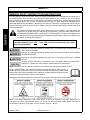 10
10
-
 11
11
-
 12
12
-
 13
13
-
 14
14
-
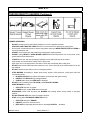 15
15
-
 16
16
-
 17
17
-
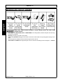 18
18
-
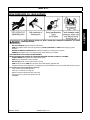 19
19
-
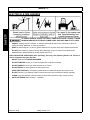 20
20
-
 21
21
-
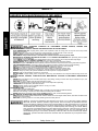 22
22
-
 23
23
-
 24
24
-
 25
25
-
 26
26
-
 27
27
-
 28
28
-
 29
29
-
 30
30
-
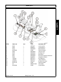 31
31
-
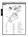 32
32
-
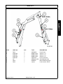 33
33
-
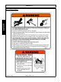 34
34
-
 35
35
-
 36
36
-
 37
37
-
 38
38
-
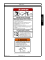 39
39
-
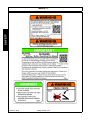 40
40
-
 41
41
-
 42
42
-
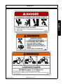 43
43
-
 44
44
-
 45
45
-
 46
46
-
 47
47
-
 48
48
-
 49
49
-
 50
50
-
 51
51
-
 52
52
-
 53
53
-
 54
54
-
 55
55
-
 56
56
-
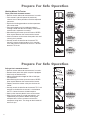 57
57
-
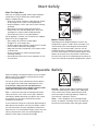 58
58
-
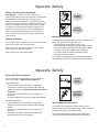 59
59
-
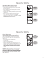 60
60
-
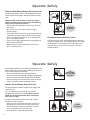 61
61
-
 62
62
-
 63
63
-
 64
64
-
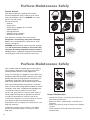 65
65
-
 66
66
-
 67
67
-
 68
68
-
 69
69
-
 70
70
-
 71
71
-
 72
72
-
 73
73
-
 74
74
-
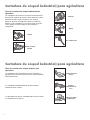 75
75
-
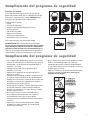 76
76
-
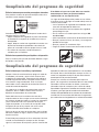 77
77
-
 78
78
-
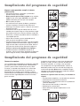 79
79
-
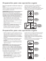 80
80
-
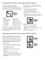 81
81
-
 82
82
-
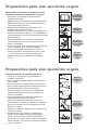 83
83
-
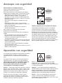 84
84
-
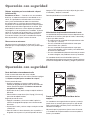 85
85
-
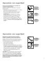 86
86
-
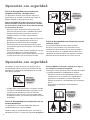 87
87
-
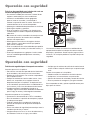 88
88
-
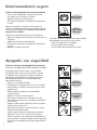 89
89
-
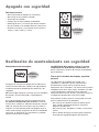 90
90
-
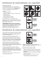 91
91
-
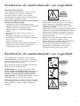 92
92
-
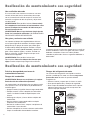 93
93
-
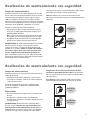 94
94
-
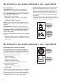 95
95
-
 96
96
-
 97
97
-
 98
98
-
 99
99
-
 100
100
-
 101
101
-
 102
102
-
 103
103
-
 104
104
-
 105
105
-
 106
106
-
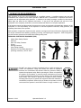 107
107
-
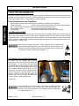 108
108
-
 109
109
-
 110
110
-
 111
111
-
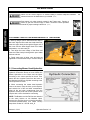 112
112
-
 113
113
-
 114
114
-
 115
115
-
 116
116
-
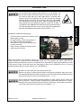 117
117
-
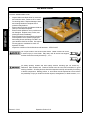 118
118
-
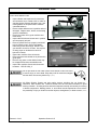 119
119
-
 120
120
-
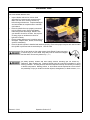 121
121
-
 122
122
-
 123
123
-
 124
124
-
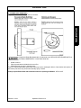 125
125
-
 126
126
-
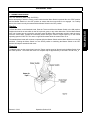 127
127
-
 128
128
-
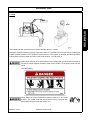 129
129
-
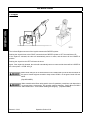 130
130
-
 131
131
-
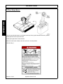 132
132
-
 133
133
-
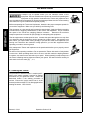 134
134
-
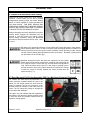 135
135
-
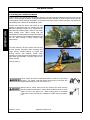 136
136
-
 137
137
-
 138
138
-
 139
139
-
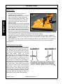 140
140
-
 141
141
-
 142
142
-
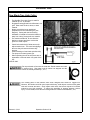 143
143
-
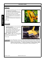 144
144
-
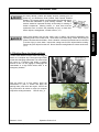 145
145
-
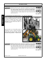 146
146
-
 147
147
-
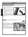 148
148
-
 149
149
-
 150
150
-
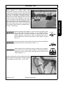 151
151
-
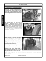 152
152
-
 153
153
-
 154
154
-
 155
155
-
 156
156
-
 157
157
-
 158
158
-
 159
159
-
 160
160
-
 161
161
-
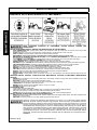 162
162
-
 163
163
-
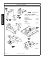 164
164
-
 165
165
-
 166
166
-
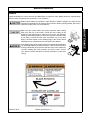 167
167
-
 168
168
-
 169
169
-
 170
170
-
 171
171
-
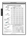 172
172
-
 173
173
-
 174
174
-
 175
175
-
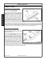 176
176
-
 177
177
-
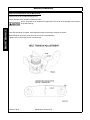 178
178
-
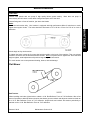 179
179
-
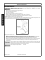 180
180
-
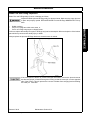 181
181
-
 182
182
-
 183
183
-
 184
184
-
 185
185
-
 186
186
-
 187
187
-
 188
188
-
 189
189
-
 190
190
-
 191
191
-
 192
192
-
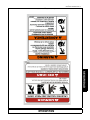 193
193
-
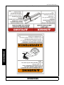 194
194
-
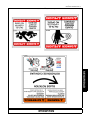 195
195
-
 196
196
-
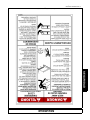 197
197
-
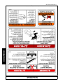 198
198
-
 199
199
-
 200
200
-
 201
201
-
 202
202
-
 203
203
-
 204
204
-
 205
205
-
 206
206
-
 207
207
-
 208
208
-
 209
209
-
 210
210
-
 211
211
-
 212
212
-
 213
213
-
 214
214
-
 215
215
-
 216
216
-
 217
217
-
 218
218
-
 219
219
-
 220
220
-
 221
221
-
 222
222
-
 223
223
-
 224
224


Alamo Industrial Samurai Manual de usuario
- Categoría
- Cortadoras de césped
- Tipo
- Manual de usuario
en otros idiomas
- English: Alamo Industrial Samurai User manual
Artículos relacionados
-
Alamo Industrial Maverick Boom Mower Manual de usuario
-
-
-
-
-
-
-