Kichler Lighting 49626BKTLED Manual de usuario
- Tipo
- Manual de usuario

Date Issued: 9/18/15
IS-49626LED-US
We’re here to help 866-558-5706
Hrs: M-F 9am to 5pm EST
WARNING:
• This fixture is intended for installation in accordance with the National Electric Code
(NEC) and all local code specifications.
• Supply wires are not intended for use through or concealed behind walls, floors, or
ceilings.
• The LED light output is strong enough to injure human eyes. Precautions must be taken
to prevent looking directly at LED’s with unaided eyes for more than a few seconds.
DIMMING: This LED fixture is compatible with most standard incandescent dimmers,
LED dimmers, and electronic low voltage dimmers. For optimal performance, an elec-
tronic low voltage dimmer should be used.
1) Read and understand all instructions and illustrations completely before proceeding
with assembly and installation of fixture.
2) If you have any doubts about how to install this fixture, or if the fixture fails to operate
completely, please contact a qualified electrician.
3) All parts must be used as indicated in the instructions. Do not substitute any parts,
leave parts out, or use any parts that are worn or broken. Failure to obey this
instruction could invalidate the UL listing, C.S.A. certification, and/or ETL listing
of this fixture.
4) Fixture is to be connected to a single branch circuit.
1) TURN OFF POWER.
IMPORTANT: Before you start, NEVER attempt any work without shutting off the
electricity until the work is done.
a) Go to the main fuse, or circuit breaker, box in your home. Place the main power
switch in the “OFF” position.
b) Unscrew the fuse(s), or switch “OFF” the circuit breaker switch(s), that control
the power to the fixture or room that you are working on.
c) Place the wall switch in the “OFF” position. If the fixture to be replaced has a
switch or pull chain, place those in the “OFF” position.
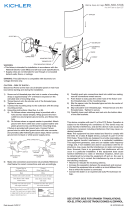
2) Unscrew glass cage retainging screws from glass cage assembly.
3) Remove all packaging materials from inside glass cage assembly.
4) Place roof down on top of glass cage assembly. Thread screws from step 2
into holes in roof. Tighten screws to secure roof to glass cage assembly.
5) Take threaded pipe from parts bag and screw in screw collar loop a minimum of 6 mm
(1/4”). Lock into place with hexnut.
6) Run another hexnut down threaded pipe almost touching first hexnut. Now screw
threaded pipe into mounting strap. Mounting strap must be positioned with extruded
thread faced into outlet box. Threaded pipe must protrude out the back of mounting
strap. Screw third hexnut onto end of threaded pipe protruding from back of
mounting strap.
7) Connect mounting strap to outlet box.
8) Unscrew the threaded ring from screw collar loop. Take canopy and pass over
screw collar loop. Approximately one half of the screw collar loop exterior threads
should be exposed. Adjust screw collar loop by turning assembly up or down in
mounting strap. Remove canopy.
9) After desired position is found, tighten both top and bottom hexnuts up against the
bottom and top of the mounting strap.
10) Slip canopy over screw collar loop and thread on threaded ring. Attach chain (with
fixture connected) to bottom of screw collar loop. Unscrew threaded ring, let canopy
and threaded ring slip down.
11) Weave electrical wire and ground wire through chain links no more than 3 inches
apart. Pass wire through threaded ring, canopy, screw collar loop, threaded pipe
and into outlet box.
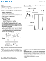
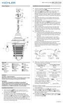
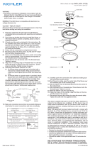
12) Grounding instructions: (See Illus. A or B).
A) On fixtures where mounting strap is provided with a hole and two raised
dimples. Wrap ground wire from outlet box around green ground screw, and
thread into hole.
B) On fixtures where a cupped washer is provided. Attach ground wire from outlet
box under cupped washer and green ground screw, and thread into mounting strap.
If fixture is provided with ground wire. Connect fixture ground wire to outlet box
ground wire with wire connector after following the above steps. Never connect
ground wire to black or white power supply wires.
13) Make wire connections. Reference chart below for correct connections and wire
accordingly.
14) Raise canopy to ceiling.
15) Secure canopy in place by tightening threaded ring onto screw collar loop.
GREEN GROUND
SCREW
CUPPED
WASHER
A
B
OUTLET BOX
GROUND
FIXTURE
GROUND
DIMPLES
WIRE CONNECTOR
(NOT PROVIDED)
OUTLET BOX
GROUND
GREEN GROUND
SCREW
FIXTURE
GROUND
Connect Black or
Red Supply Wire to:
Connect
White Supply Wire to:
Black White
*Parallel cord (round & smooth) *Parallel cord (square & ridged)
Clear, Brown, Gold or Black
without tracer
Clear, Brown, Gold or Black
with tracer
Insulated wire (other than green)
with copper conductor
Insulated wire (other than green)
with silver conductor
*Note: When parallel wires (SPT I & SPT II)
are used. The neutral wire is square shaped
or ridged and the other wire will be round in
shape or smooth (see illus.)
Neutral Wire
This device complies with part 15 of the FCC Rules. Operation is subject to the following
two conditions: (1) This device may not cause harmful interference, and (2) this device
must accept any interference received, including interference that may cause undesired
operation.
Note: This equipment has been tested and found to comply with the limits for a Class B
digital device, pursuant to part 15 of the FCC Rules. These limits are designed to pro-
vide reasonable protection against harmful interference in a residential installation. This
equipment generates, uses and can radiate radio frequency energy and, if not installed
and used in accordance with the instructions, may cause harmful interference to radio
communications. However, there is no guarantee that interference will not occur in a par-
ticular installation. If this equipment does cause harmful interference to radio or television
reception, which can be determined by turning the equipment off and on, the user is
encouraged to try to correct the interference by one or more of the following measures:
• Reorient or relocate the receiving antenna.
• Increase the separation between the equipment and receiver.
• Connect the equipment into an outlet on a circuit different from that to which the receiver
is connected.
• Consult the dealer or an experienced radio/TV technician for help.
SEE OTHER SIDE FOR SPANISH TRANSLATIONS.
VEA EL OTRO LADO DE TRADUCCIONES AL ESPAÑOL.
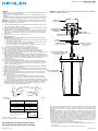
MOUNTING STRAP
ABRAZADERA DE
MONTAJE
HEXNUT
TUERCA HEXAGONAL
THREADED PIPE
TUBO ROSCADO
CANOPY
ESCUDETE
THREADED RING
ANILLO ROSCADO
SCREW COLLAR LOOP
OJAL DE COLLAR
ROSCADO
OUTLET BOX
CAJA DE SALIDA
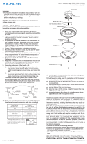
NOTE: The fixture 49626 is shown. Your fixture may vary. The installation
instructions will be the same.
ROOF
TECHO
GLASS CAGE RETAINING SCREW
TORNILLOS QUE SUJETAN EL
JAULA DE VIDRIO
GLASS CAGE ASSEMBLY
JAULA DE VIDRIO

Date Issued: 10/23/15
IS-49626LED-US
We’re here to help 866-558-5706
Hrs: M-F 9am to 5pm EST
ADVERTENCIA:
• Este artefacto está hecho para ser instalado de acuerdo con el Código Nacional de
Electricidad (NEC) y todas las especificaciones del código local.
• Los alambres suministrados no tienen el propósito de ser utilizados a través de o es
condidos detrás de paredes, pisos o techos.
• La salida de luz del LED es lo suficientemente fuerte para lesionar los ojos humanos.
Deben tomarse precauciones para evitar mirar directamente con los ojos sin protección
durante poco más de unos cuantos segundos.
OSCURECIMIENTO: Este artefacto de LED es compatible con la mayoria d los regula-
dores de intensidad incandescente estándar, los reguladores de intensidad de LED, y los
reguladores de intensidad electrónicos de bajo voltaje. Para un desempeño óptimo,
deberá ser utilizado un regulador de intensidad electrónico de bajo voltaje.
1) Lea y entienda completamente todas las instrucciones e ilustraciones antes de proceder
con el ensamblaje e instalación del artefacto.
2) Si usted tiene dudas sobre como instalar este artefacto, o si el artefacto no funciona
completamente, por favor contacte a un electricista calificado.
3) Todas las partes deben ser utilizadas tal como se indica en las instrucciones. No
sustituya ninguna de las partes, deje fuera algunas partes, o utilice cualquier parte
que esté desgastada o rota. El no obedecer esta instrucción podría invalidar el listado
en UL, la certificación de C.S.A. y/o el listado en ETL de este artefacto.
4) El artefacto debe ser conectado a un circuito de un solo ramal.
1) APAGAR LA ALIMENTACIÓN DE ENERGIE ELÈTRICA.
IMPORTANTE: Antes de comenzar, NUNCA trate de trabajar sin antes desconectar
la corriente hasta que el trabajo se termine.
a) Vaya a la caja principal de fusibles, o interruptor o caja de circuitos de su casa.
Coloque el interruptor de la corriente principal en posición de apagado “OFF”.
b) Desatornille el (los) fusible (s), o coloque el interruptor o interruptores del breaker en
posición de apagado “OFF”, que controla (n) la corriente hacia el artefacto o
habitación donde está trabajando.
c) Coloque el interruptor de pared en posición de apagado “OFF”. Si el artefacto
que se va a reemplazar tiene un interruptor o cadena que se jala, colóquelos en
la posición de apagado “OFF”.
2) Desatornille los tornillos que sujetan el jaula de vidrio del jaula de vidrio.
3) Saque todos los materiales de envío de adentro del jaula de vidrio.
4) Coloque el techo encima del jaula de vidrio. Enrosque los tornillos del paso 2 en los
agujeros en el techo. Apriete los tornillos para asegurar el techo al jaula de vidrio.
5) Seque el tubo roscado de la bolsa de piezas y atornille en el ojal de collar roscado
un minimo de 6 mm (1/4”). Inmovilice en el lugar con la tuerca hexagonal.
6) Instale otra tuerca hexagonal en el tubo roscado casi tocando la primera tuerca
hexagonal. Ahora, atornille el tubo roscado en la abrazadera de montaje. La abrazadera
de montaje se debe colocar con la rosca extruida mirando hacia la caja de salida. El
tubo roscado debe sobresalir atrás de la abrazadera de montaje. Atornille la tercera
tuerca hexagonal en el extremo del tubo roscado que sobresale de la parte posterior
de la abrazadera de montaje.
7) Conecte la abrazadera de montaje a la caja de salida.
8) Destornille el anillo roscado del ojal de collar roscado deben sobresalir aproximadamente
la mitad. Ajuste el ojal del collar roscado girando el conjunto hacia arriba a abajo, en
la abrazadera de montaje. Retire el escudete.
9) Después que encuentre la posición deseada, apriete la tuerca hexagonal superior
contra el fondo de la abrazadera de montaje.
10) Después de encontrar la posición deseada, apriete ambas tuercas hexagonales, la
superior y la inferior, arriba contra las partes superior e inferior de la abrazadera de
montaje.
11) Pase el alambre eléctrico y el alambre de tierra a través de los estabones de la
cadena, a espacios maximos de 3 pulgadas. Pase el alambre a través del anillo
roscado, el escudete, el ojal de collar roscado, el tubo roscado y dentro de la caja
de salida.
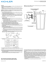
12) Instrucciones de conexión a tierra (Vea la ilustración A o B)
A) En artefactos donde se provee la abrazadera de montaje con un agujero y dos
depresiones onduladas: Envuelva el alambre de tierra de la caja de salida
alrededor del tornillo de tierra verde y rosque en el agujero.
B) En artefactos donde se provee una arandela cóncava. Acople el alambre de
tierra de la caja de salida debajo de la arandela cóncava y del tornillo de tierra
verde, y rosque el tornillo en la abrazadera de montaje.
Si el artefacto está provisto con alambre de tierra: Conecte el alambre de tierra del
artefacto con el alambre de tierra de la caja de salida con un conector de alambre.
GREEN GROUND
SCREW
CUPPED
WASHER
A
B
OUTLET BOX
GROUND
FIXTURE
GROUND
DIMPLES
WIRE CONNECTOR
(NOT PROVIDED)
OUTLET BOX
GROUND
GREEN GROUND
SCREW
FIXTURE
GROUND
Connect Black or
Red Supply Wire to:
Connect
White Supply Wire to:
Black White
*Parallel cord (round & smooth) *Parallel cord (square & ridged)
Clear, Brown, Gold or Black
without tracer
Clear, Brown, Gold or Black
with tracer
Insulated wire (other than green)
with copper conductor
Insulated wire (other than green)
with silver conductor
*Note: When parallel wires (SPT I & SPT II)
are used. The neutral wire is square shaped
or ridged and the other wire will be round in
shape or smooth (see illus.)
Neutral Wire
Este artefacto cumple con la parte 15 de las Normas de la FCC. El funcionamiento está sujeto a las siguientes dos condiciones: (1) Este artefacto no puede causar interferencia perju-
dicial, y (2) este artefacto debe aceptar cualquier interferencia recibida, inclusive interferencia que puede causar una operación no deseada.
Nota: Este equipo ha sido probado y se comprobó que cumple con los límites para un artefacto digital Clase B, de conformidad con la parte 15 de las Normas de la FCC. Estos límites
están diseñados para proporcionar una protección razonable contra interferencia perjudicial en una instalación residencial. Este equipo genera, usa y puede radiar energía de radio
frecuencia y, si no se instala y usa de acuerdo con las instrucciones, puede causar interferencia perjudicial las comunicaciones de radio. Sin embargo, no hay garantía que la interfer-
encia no ocurrirá en una instalación en particular. Si este equipo sí causa interferencia perjudicial a la recepción de radio o televisión, que puede ser determinado enciendo y apagando
el equipo, se alienta al usuario a que trata de corregir la interferencia con una o más de las siguientes medidas:
• Reoriente o cambie de lugar la antena de recepción.
• Aumente la separación entre el equipo y el receptor.
• Conecte el equipo en un receptáculo en un circuito diferente de donde está conectado el receptor.
• Consulte al distribuidor o a un técnico de radio/TV experimentado para ayuda.
SEE OTHER SIDE FOR ENGLISH TRANSLATIONS.
VEA EL OTRO LADO DE TRADUCCIONES AL INGLÉS.
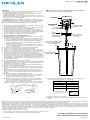
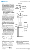
MOUNTING STRAP
ABRAZADERA DE
MONTAJE
HEXNUT
TUERCA HEXAGONAL
THREADED PIPE
TUBO ROSCADO
CANOPY
ESCUDETE
THREADED RING
ANILLO ROSCADO
SCREW COLLAR LOOP
OJAL DE COLLAR
ROSCADO
OUTLET BOX
CAJA DE SALIDA
13) Haga las conexiones de alambres. Vea la tabla de referencia de abajo para las
conexiones correctas y los alambres correspondientes.
11) Levante el escudete hasta el cielorraso.
12) Asegure en el escudete en el lugar apretando el anillo roscado en el ojal de collar
roscado.
GLASS CAGE RETAINING SCREW
TORNILLOS QUE SUJETAN EL
JAULA DE VIDRIO
ROOF
TECHO
GLASS CAGE ASSEMBLY
JAULA DE VIDRIO
NOTA: Se muestra el artefacto 49626. Su artefacto puede variar. Las
instrucciones de instalación serán las mismas.

Date Issued: 10/23/15
IS-49626LED-CB
We’re here to help 866-558-5706
Hrs: M-F 9am to 5pm EST
WARNING:
• This fixture is intended for installation in accordance with the National Electric Code
(NEC) and all local code specifications.
• Supply wires are not intended for use through or concealed behind walls, floors, or
ceilings.
• The LED light output is strong enough to injure human eyes. Precautions must be taken
to prevent looking directly at LED’s with unaided eyes for more than a few seconds.
DIMMING: This LED fixture is compatible with most standard incandescent dimmers,
LED dimmers, and electronic low voltage dimmers. For optimal performance, an elec-
tronic low voltage dimmer should be used.
1) Read and understand all instructions and illustrations completely before proceeding
with assembly and installation of fixture.
2) If you have any doubts about how to install this fixture, or if the fixture fails to operate
completely, please contact a qualified electrician.
3) All parts must be used as indicated in the instructions. Do not substitute any parts,
leave parts out, or use any parts that are worn or broken. Failure to obey this
instruction could invalidate the UL listing, C.S.A. certification, and/or ETL listing
of this fixture.
4) Fixture is to be connected to a single branch circuit.
1) TURN OFF POWER.
IMPORTANT: Before you start, NEVER attempt any work without shutting off the
electricity until the work is done.
a) Go to the main fuse, or circuit breaker, box in your home. Place the main power
switch in the “OFF” position.
b) Unscrew the fuse(s), or switch “OFF” the circuit breaker switch(s), that control
the power to the fixture or room that you are working on.
c) Place the wall switch in the “OFF” position. If the fixture to be replaced has a
switch or pull chain, place those in the “OFF” position.
2) Unscrew glass cage retainging screws from glass cage assembly.
3) Remove all packaging materials from inside glass cage assembly.
4) Place roof down on top of glass cage assembly. Thread screws from step 2
into holes in roof. Tighten screws to secure roof to glass cage assembly.
5) Take threaded pipe from parts bag and screw in screw collar loop a minimum of 6 mm
(1/4”). Lock into place with hexnut.
6) Run another hexnut down threaded pipe almost touching first hexnut. Now screw
threaded pipe into mounting strap. Mounting strap must be positioned with extruded
thread faced into outlet box. Threaded pipe must protrude out the back of mounting
strap. Screw third hexnut onto end of threaded pipe protruding from back of
mounting strap.
7) Connect mounting strap to outlet box.
8) Unscrew the threaded ring from screw collar loop. Take canopy and pass over screw
collar loop. Approximately one half of the screw collar loop exterior threads should
be exposed. Adjust screw collar loop by turning assembly up or down in mounting
strap. Remove canopy.
9) After desired position is found, tighten both top and bottom hexnuts up against the
bottom and top of the mounting strap.
10) Slip canopy over screw collar loop and thread on threaded ring. Attach chain (with
fixture connected) to bottom of screw collar loop. Unscrew threaded ring, let canopy
and threaded ring slip down.
11) Weave electrical wire and ground wire through chain links no more than 3 inches
apart. Pass wire through threaded ring, canopy, screw collar loop, threaded pipe
and into outlet box.
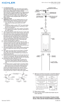
12) Connect fixture ground wire to outlet box ground wire with wire connector. (Not
provided.) Never connect ground wire to black or white power supply wire.
13) Make wire connections (connectors not provided). Reference chart below for correct
connections and wire accordingly.
14) Raise canopy to ceiling.
15) Secure canopy in place by tightening threaded ring onto screw collar loop.
Connect Black or
Red Supply Wire to:
Connect
White Supply Wire to:
Black White
*Parallel cord (round & smooth) *Parallel cord (square & ridged)
Clear, Brown, Gold or Black
without tracer
Clear, Brown, Gold or Black
with tracer
Insulated wire (other than green)
with copper conductor
Insulated wire (other than green)
with silver conductor
*Note: When parallel wires (SPT I & SPT II)
are used. The neutral wire is square shaped
or ridged and the other wire will be round in
shape or smooth (see illus.)
Neutral Wire
This device complies with part 15 of the FCC Rules. Operation is subject to the following
two conditions: (1) This device may not cause harmful interference, and (2) this device
must accept any interference received, including interference that may cause undesired
operation.
Note: This equipment has been tested and found to comply with the limits for a Class B
digital device, pursuant to part 15 of the FCC Rules. These limits are designed to pro-
vide reasonable protection against harmful interference in a residential installation. This
equipment generates, uses and can radiate radio frequency energy and, if not installed
and used in accordance with the instructions, may cause harmful interference to radio
communications. However, there is no guarantee that interference will not occur in a par-
ticular installation. If this equipment does cause harmful interference to radio or television
reception, which can be determined by turning the equipment off and on, the user is
encouraged to try to correct the interference by one or more of the following measures:
• Reorient or relocate the receiving antenna.
• Increase the separation between the equipment and receiver.
• Connect the equipment into an outlet on a circuit different from that to which the receiver
is connected.
• Consult the dealer or an experienced radio/TV technician for help.
INSTRUCTIONS
For Assembling and Installing Fixtures in Canada
Pour L’assemblage et L’installation Au Canada
SEE OTHER SIDE FOR CANADIAN FRENCH TRANSLATIONS.
VOIR L’AUTRE CÔTÉ POUR LES CANADIENS TRADUCTIONS EN
FRANÇAIS.
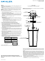
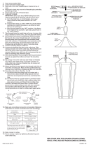
MOUNTING STRAP
PATTE DE FIXATION
THREADED PIPE
TUBE FILETÉ
SCREW COLLAR LOOP
COLLIER-ÉCROU
CANOPY
CACHE
THREADED RING
BAGUE FILETÉE
OUTLET BOX
BOÎTE DE JONCTION
HEXNUT
ECROU HEXAGONAL
ROOF
TECHO
GLASS CAGE RETAINING
SCREWS
VIS DE FIXATION DE LA
CAGE DE VERRE
GLASS CAGE ASSEMBLY
ASSEMBLAGE DE CAGE DE VERRE
NOTE: The fixture 49626 is shown. Your fixture may vary. The installation
instructions will be the same.

Date Issued: 10/23/15
IS-49626LED-CB
We’re here to help 866-558-5706
Hrs: M-F 9am to 5pm EST
AVERTISSEMENT:
• Ce luminaire doit être installé conformément aux codes d’électricité nationaux (NEC)
et satisfaire toutes les spécifications des codes locaux.
• Les câbles d’alimentation ne doivent pas être utilisés à travers ou derrière des parois,
sols ou plafonds.
• L’intensité de la lumière des LED peut endommager les yeux. Prendre toutes les
précautions nécessaires pour ne pas regarder directement dans les LED sans protection
pendant plusieurs secondes.
GRADATION: Ce luminaire LED est compatible avec la plupart des gradateurs standard
à incandescence, gradateurs LED, et gradateurs électroniques a basse tension. Pour
une performance optimale, utiliser un gradateur électronique à basse tension.
1) Lire et comprendre toutes les instructions et illustrations avant de procéder au montage
et à l’installation du luminaire.
2) En cas de doute sur l’installation de ce luminaire, ou si le luminaire ne fonctionne
pas correctement, prière de contacter un électricien agréé.
3) Utiliser toutes les pièces selon les instructions. Ne pas substituer de pièces, exclure
certaines pièces du montage ou se servir de pièces usées ou endommagées. Le
non-respect de ces instructions risque d’annuler l’homologation UL, le certificat
C.S.A. ainsi que l’homologation ETL de ce luminaire.
4) Le luminaire peut être connecté à un circuit dédié.
1) COUPER L’ALIMENTATION SECTEUR.
IMPORTANT: TOUJOURS couper l’électricité avant de commencer le travail.
a) Localiser le coffret à fusibles ou le disjoncteur du domicile. Mettre l’interrupteur
principal en position d’Arrêt.
b) Dévisser le ou les fusibles (ou mettre le disjoncteur sur Arrêt) qui contrôlent
l’alimentation vers le luminaire ou la pièce dans laquelle le travail est effectué.
c) Mettre l’interrupteur mural en position d’Arrêt. Si le luminaire à remplacer est doté
d’un interrupteur ou d’une chaîne connectée à l‘interrupteur, placer ces éléments
en position d’Arrêt.
2) Desserrer les vis de fixation de la cage de verre à partir de l’assemblage de cage de
verre.
3) Retirer tous les matériaux d’emballage de l’intérieur du luminaire.
4) Placer le toit sur le dessus du luminaire. Serrer les vis de l’étape 2 dans les trous du
toit. Resserrer les vis pour fixer le toit au l’assemblage de cage de verre.
5) Visser le tube fileté (qui se trouve avec les pièces détachées) dans le collier-écrou, sur
une longueur minimum de 6 mm (1/4 po). Fixer avec un écrou hexagonal.
6) Visser un second écrou hexagonal de manière à ce qu’il touche presque le premier.
Visser ensuite le tube fileté sur la patte de fixation, en le faisant dépasser et en
dirigeant la partie filetée des vis vers la boîte de jonction. Visser un troisième écrou
hexagonal sur l’extrémité du tube fileté sortant de l’arrière de la sangle de montage.
Visser un troisième écrou hexagonal sur l’extrémité du tube fileté sortant de l’arrière
de la sangle de montage.
7) Connecter la patte de fixation à la boîte de jonction.
8) Dévisser la bague filetée du collier-écrou. Passer le cache sur le collier-écrou.
Environ la moitié de filetage extérieur de celui-ci doit être apparent. Fixer le collier-écrou
en faisant pivoter l’assemblage vers le haut ou vers le bas. Enlever le cache.
9) Une fois bien positionné, serrer les deux écrous hexagonaux, supérieur et inférieur,
contre le dessous et le dessus de la sangle de montage.
10) Glisser le cache sur le collier-écrou et enfiler sur la bague filetée. Attacher la chaine
(avec l’assemblage connecté) au bas du collier-écrou. Dévisser la bague filetée et
laisser glisser le cache et la bague filetée.
11) Entrelacer le fil électrque et le fil de mise á la terre et faire passer le tout dans les
anneaux de la chaîne en espaçant au maximum de 3 po. Passer le fil dans la bague
filetée, le cache, le collier-écrou, le tube fileté et la boîte de jonction.
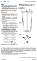
12) Connecter le fil de terre du luminaire à la boîte de jonction fil de terre avec le
connecteur du câble. (Non fournie.) Ne jamais raccorder le fil de terre au noir ou le fil
d’alimentation blanc.
13) Connecter les fils (connecteurs non fournis). Se reporter au tableau ci-dessous pour
faire les connexions.
14) Placer le cache au plafond.
15) Fixer le cache en serrant la bague filetée sur le collier-écrou.
Cet appareil est conforme à la section 15 de la réglementation de la FCC. L’exploitation
est soumise aux deux conditions suivantes : (1) Cet équipement ne doit pas causer d’in-
terférences nuisibles, et (2) cet équipement doit accepter toute interférence reçue, y com-
pris les interférences risquant d’engendrer un fonctionnement indésirable.
Remarque: Des tests ont confirmé que ce matériel respecte les limites d’un dispositif
numérique de catégorie B, en vertu de la section 15 de la réglementation de la FCC.
Ces limites ont été conçues pour fournir une protection raisonnable contre le brouillage
nuisible d’une installation résidentielle. Cet équipement génère, utilise et peut rayonner
de l’énergie radiofréquence et, s’il n’est pas installé et utilisé selon les instructions, peut
causer de l’interférence nuisible aux communications de radio. Cependant, il est néan-
moins possible qu’il y ait de l’interférence dans une installation en particulier. Si cet équi-
pement cause du brouillage nuisible à la réception du signal de radio ou de télévision, ce
qui peut être déterminé en éteignant puis en rallumant l’appareil, l’usager peut essayer de
corriger l’interférence en appliquant une des mesures suivantes :
• Réorienter l’antenne de réception ou changer son emplacement.
• Augmenter la distance séparant l’équipement et le récepteur.
• Brancher le matériel dans la prise de courant d’un circuit différent de celui auquel le
récepteur est branché.
• Consulter le revendeur ou un technicien radio/télé d’expérience.
INSTRUCTIONS
For Assembling and Installing Fixtures in Canada
Pour L’assemblage et L’installation Au Canada
SEE OTHER SIDE FOR ENGLISH TRANSLATIONS.
VOIR L’AUTRE CÔTÉ DES TRADUCTIONS EN ANGLAIS.
Connecter le fil noir ou
rouge de la boite
Connecter le fil blanc de la boîte
A Noir A Blanc
*Au cordon parallèle (rond et lisse)
*Au cordon parallele (à angles droits el strié)
Au bransparent, doré, marron, ou
noir sans fil distinctif
Au transparent, doré, marron, ou
noir avec un til distinctif
Fil isolé (sauf fil vert) avec
conducteur en cuivre
Fil isolé (sauf fil vert) avec
conducteur en argent
*Remarque: Avec emploi d’un fil paralléle
(SPT I et SPT II). Le fil neutre est á angles
droits ou strié et l’autre fil doit étre rond ou
lisse (Voir le schéma).
Fil Neutre
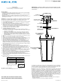
MOUNTING STRAP
PATTE DE FIXATION
THREADED PIPE
TUBE FILETÉ
SCREW COLLAR LOOP
COLLIER-ÉCROU
CANOPY
CACHE
THREADED RING
BAGUE FILETÉE
OUTLET BOX
BOÎTE DE JONCTION
HEXNUT
ECROU HEXAGONAL
REMARQUE: Le luminaire nº49626 est représenté. Votre luminaire peut dif-
férer de l’illustration. Toutefois, les instructions sont les mêmes pour tous
les luminaires.
ROOF
TECHO
GLASS CAGE RETAINING
SCREWS
VIS DE FIXATION DE LA
CAGE DE VERRE
GLASS CAGE ASSEMBLY
ASSEMBLAGE DE CAGE
DE VERRE
-
 1
1
-
 2
2
-
 3
3
-
 4
4


Kichler Lighting 49626BKTLED Manual de usuario
- Tipo
- Manual de usuario
en otros idiomas
Artículos relacionados
-
 Kichler Lighting 49624BKTLED Manual de usuario
-
 Kichler Lighting 49622BKTLED Manual de usuario
-
 Kichler Lighting 49387OZ Manual de usuario
-
 Kichler Lighting 49625BKTLED Manual de usuario
-
 Kichler Lighting 10797NILED Manual de usuario
-
 Kichler Lighting 49939WZC Manual de usuario
-
 Kichler Lighting 49718OZ Manual de usuario
-
 Kichler Lighting 49517OZ Manual de usuario
-
 Kichler Lighting 11131AZTLED Manual de usuario
-
 Kichler Lighting 11134AZTLED Manual de usuario


