
This unit is equipped with a thermally protected class “P” ballast.
1) Turn off power supply at fuse box before installing fixture
2) Remove ballast cover.
3) Remove 7/8” diameter wireway knockout at center of fixture. Insert bushing in hole.
Remove four (4) oval mounting slot knock outs (one in each corner).
4) Position housing on ceiling and mark ceiling at mounting slots. Remove housing.
5) Be certain there are no obstructions above ceiling at mounting slot location.
6) Drill four (4) marked locations with 3/8” diameter drill.
7) 2x2 Housing Only:
Push lamp clip into 1/4” diameter hole located near center of housing. Rotate clip
to be parallel with lamp.
8) Pass wires from outlet box through bushed center hole
in housing.
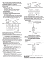
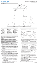
9) Slip flat washer onto 3” screw. Pass screw
through oval mounting slot of housing. Assemble spring
toggle onto screw (as shown). Repeat at all corners.
Pass the toggles thru the 3/8”diameter holes in the
ceiling (as shown on the right). Tighten screws.
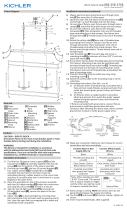
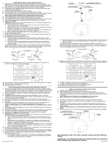
10) Grounding instructions: (See Illus. A or B).
A) On fixtures where mounting strap is provided with a hole and two raised
dimples. Wrap ground wire from outlet box around green ground screw, and
thread into hole.
B) On fixtures where a cupped washer is provided. Attach ground wire from
outlet box under cupped washer and green ground screw, and thread into
mounting strap.
If fixture is provided with ground wire. Connect fixture ground wire to outlet box
ground wire with wire connector (not provided.) after following the above steps.
Never connect ground wire to black or white power supply wires.
11) Make wire connections (connectors not provided). Reference chart below for
correct connections and wire accordingly.
12) Re-attach ballast cover.
CAUTION: BALLAST MUST BE REPLACED BY A QUALIFIED ELECTRI-
CIAN.
Esta unidad está equipada con un reactor de clase “P” protegido térmicamente.
1) Apague el suministro de potencia eléctrica a la caja de fusibles antes de instalar el
artefacto.
2) Retire la tapa del reactor.
3) Quite el agujero ciego del conducto de alambres de 7/8” de diámetro en el centro
del artefacto. Inserte el manguito en el agujero. Quite los cuatro (4) agujeros
ciegos de la ranura de montaje (uno en cada esquina).
4) Coloque la cubierta en el cielo raso y marque el cielo raso en las ranuras de
montaje. Retire la cubierta.
5) Asegúrese de que no hayan obstrucciones arriba en el cielo raso en el lugar de la
ranura de montaje.
6) Perfore los cuatro (4) lugares marcados con una barrena de 3/8” de diámetro.
7) Solamente cubiertas de 2 x 2:
Empuje la presilla de la lámpara en el agujero de 1/4” de diámetro localizado
cerca del centro de la cubierta. Gire la presilla para que esté paralela con la
lámpara.
8) Pase los alambres de la caja de salida a través del
agujero central con manguito en la cubierta.
9) Resbale la arandela plana en el tornillo de 3”. Pase el
tornillo a través de la ranura de montaje ovalada de la
cubierta. Monte el conmutador de resorte en el tornillo
(como se muestra). Repita en todas las esquinas. Pase
las conexiones articuladas a través de los agujeros de
3/8” de diámetro en el cielo raso (como se muestra a la derecha). Apriete los
tornillos.
10) Instrucciones de conexión a tierra solamente para los Estados Unidos.
(Vea la ilustracion A o B).
A) En las lámparas que tienen el fleje, de montaje con un agujero y dos hoyue
los realzados. Enrollar el alambre a tierra de la caja tomacorriente
alrededor del tornillo verde y pasarlo por el aquiero.
B) En las lámparas con una arandela acopada. Fijar el alambre a tierra de la
caja tomacorriente del ajo de la arandela acoada y tornillo verde, y paser
por el fleje de montaje.
Si la lámpara viene con alambre a tierra. Conecter el alambre a tierra de la
lámpara al alambre a tierra de la caja tomacorriente con un conector de alambres
(no incluido) espués de seguir los pasos anteriores. Nunca conectar el alambra a
tierra a los alambres eléctros negro o blanco.
11) Haga les conexiones de los alambres (no se proveen los connectores.) La tabla
de referencia de abajo indica las conexiones correctas y los alambres
correspondientes.
12) Vuelva a instalar la cubierta del reactor.
PRECAUCIÓN: EL ESTABILIZADOR DE TENSIÓN LO DEBE CAMBIAR
UN ELECTRICISTA IDÓNEO.
DECORATIVE FRAME INSTALLATION INSTRUCTIONS
INSTRUCCIONES PARA INSTALAR EL MARCO DECORATIVO
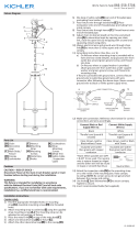
After the fixture housiing has been installed to your ceiling, attach the
decorative frame as follows:
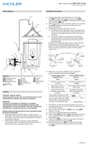
1) Hook one side of decorative frame onto housing edge.
2) Push opposite side of decorative frame upward past housing edge.
3) Shift decorative frame in direction of hooked side.
4) Drop decorative frame into place.
Una vez que se ha instalado la caja del artefacto en su techo, una el
marco decorativo de la manera siguiente:
1) Enganche un lado del marco decorativo en la orilla de la caja.
2) Empuje el lado opuesto del marco decorativo hacia arriba pasando la
orilla de la caja.
3) Desplace el marco decorativo en dirección del lado enganchado.
4) Deje caer el marco decorativo en su lugar.
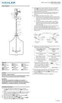
Squeeze to release from beneath metal clip.
CEILING
HOUSING
Connect Black or
Red Supply Wire to:
Connect
White Supply Wire to:
Black White
*Parallel cord (round & smooth) *Parallel cord (square & ridged)
Clear, Brown, Gold or Black
without tracer
Clear, Brown, Gold or Black
with tracer
Insulated wire (other than green)
with copper conductor
Insulated wire (other than green)
with silver conductor
*Note: When parallel wires (SPT I & SPT II)
are used. The neutral wire is square shaped
or ridged and the other wire will be round in
shape or smooth (see illus.)
Neutral Wire
Conectar el alambre de
suministro negro o rojo al
Conectar el alambre de
suministro blanco al
Negro Blanco
*Cordon paralelo (redondo y liso)
*Cordon paralelo (cuadrado y estriado)
Claro, marrón, amarillio o negro
sin hebra identificadora
Claro, marrón, amarillio o negro
con hebra identificadora
Alambre aislado (diferente del verde)
con conductor de cobre
Alambre aislado (diferente del
verde) con conductor de plata
*Nota: Cuando se utiliza alambre paralelo
(SPT I y SPT II). El alambre neutro es de forma
cuadrada o estriada y el otro alambre será de
forma redonda o lisa. (Vea la ilustracíón).
Hilo Neutral
GREEN GROUND
SCREW
CUPPED
WASHER
A
B
OUTLET BOX
GROUND
FIXTURE
GROUND
DIMPLES
WIRE CONNECTOR
(NOT PROVIDED)
OUTLET BOX
GROUND
GREEN GROUND
SCREW
FIXTURE
GROUND
ARANDELA
CONCAVA
A
B
TIERRA DE LA
CAJA DE SALIDA
TORNILLO DE TIERRA,
VERDE
DEPRESIONES
TIERRA
ARTEFACTO
CONECTOR DE ALAMBRE
(NO SE PROVEE)
TIERRA DE LA
CAJA DE SALIDA
TORNILLO DE TIERRA,
VERDE
TIERRA
ARTEFACTO
Presione para soltar de las presillas
metálicas.
CEILO RASO
CUBIERTA
HOUSING
CAJA
DECORATIVE FRAME
MARCO DECORATIVO
Date Issued: 6/11/10 IS-10315-US
-
 1
1

Kichler Lighting 10315WHLED Manual de usuario
- Tipo
- Manual de usuario
- Este manual también es adecuado para
en otros idiomas
Artículos relacionados
-
 Kichler Lighting 42467WMZ Manual de usuario
-
 Kichler Lighting 42498NI Manual de usuario
-
 Kichler Lighting 42496NI Manual de usuario
-
 Kichler Lighting 42497NI Manual de usuario
-
 Kichler Lighting 49876BK Manual de usuario
-
 Kichler Lighting 44023NBR Manual de usuario
-
 Kichler Lighting 43189AUB Manual de usuario
-
 Kichler Lighting 4900NI Manual de usuario


