
IS-42496-US
We’re here to help 866-558-5706
Hrs: M-F 9am to 5pm EST
6) Adjust chain to desired length at this me and aach
chain[A] to decorave loops by opening one chain
link, close the open links by wrapping with a towel and
squeezing closed using pliers.
7) Weave electrical wire and ground wire through chain
links no more than 3 inches apart and run into the
canopy.
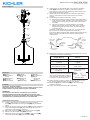
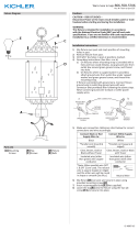
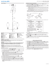
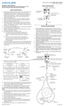
8) Grounding instrucons: (See Illus. a or b).
a) On xtures where mounng strap is provided with a
hole and two raised dimples, wrap ground wire from
outlet box around green ground screw, and thread
into hole.
b) On xtures where a cupped washer is provided,
aach ground wire from outlet box under cupped
washer and green ground screw, and thread into
mounng strap.
If xture is provided with ground wire, connect xture
ground wire to outlet box ground wire with wire
connector (Not provided) aer following the above steps.
Never connect ground wire to black or white power
supply wires.
9) Make wire connecon. Reference chart below for correct
connecons and wire accordingly.
Connect Black or Red
Supply Wire to:
Connect White Supply
Wire to:
Black White
*Parallel cord (round &
smooth)
*Parallel cord (square &
ridged)
Clear, Brown, Gold or
Black without Tracer
Clear, Brown, Gold or Black
with Tracer
Insulated wire (other
than green) with copper
conductor
Insulated wire (other
than green) with silver
conductor
*Note: When parallel wire (SPT
1 & SPT 2) are used. The neutral
wire is square shaped or ridged
and the other wire will be round
in shape or smooth (See illus.)
Neutral Wire
10) Raise canopy to ceiling. Note: Be certain wires do not
get pinched between the canopy and ceiling.
11) Use knobs[J] and lockwashers[K] to secure canopy.
Tighten to secure.
12) Insert recommended bulbs (Not supplied).
GREEN GROUND
SCREW
CUPPED
WASHER
OUTLET BOX
GROUND
FIXTURE
GROUND
DIMPLES
WIRE CONNECTOR
OUTLET BOX
GROUND
GREEN GROUND
SCREW
FIXTURE
GROUND
a
b
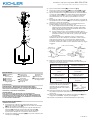
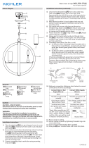
Fixture Diagram
Parts List
[A] Chain
[B] Decorative
Loop
[C] Main Body
[D] Canopy
[E] Lockwasher
[F] Hexnut
[G] Mounting
Strap
[H] Mounting
Screws
[I] Outlet Box
[J] Knobs
[K] Lockwashers
[L] Strap
Mounting
Screws
[M] Metal Trim
Cauons
CAUTION – RISK OF SHOCK –
Disconnect Power at the main circuit breaker panel or main
fusebox before starng and during the installaon.
WARNING:
This xture is intended for installaon in accordance
with the Naonal Electrical Code (NEC) and all local code
specicaons. If you are not familiar with code requirements,
installaon by a cered electrician is recommended.
Installaon Instrucons
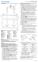
1) Find the appropriate threaded holes on mounng
strap[G]. Assemble mounng screws[H] into threaded
holes.
2) Aach mounng strap to outlet box[I] using the supplied
strap mounng screws[L]. The mounng strap can be
adjusted to suit posion of xture.
3) Place the metal trim[M] on top of the main body[C].
4) Aach one decorave loop[B] to xture.
5) Aach the other decorave loop[B] to the canopy[D]
using the lockwasher[E] and the hexnut[F].
I
G
L
E
F
H
D
K
J
B
A
B
C
M

IS-42496-US
Estamos aquí para ayudarle 866-558-5706
Horario: Lunes-Viernes 9am a 5pm EST (hora ocial del este)
4) Fije un anillo decoravo [B] al artefacto [C].
5) Fije el otro anillo decoravo [B] al escudete [D] usando
la arandela de seguridad [E] y la tuerca hexagonal [F].
6) Ajuste la cadena a la longitud deseada en este momento
y sujete la cadena [A] a los anillos decoravos abriendo
un eslabón de la cadena; cierre los eslabones abiertos
envolviéndolos con un paño y apretándolos con una
pinza.
7) Entrelace el cable eléctrico y el cable de erra a través de
los eslabones de la cadena [H] a no más de 3 pulgadas de
distancia y hacia el escudete.
8) Instrucciones de conexión a erra solamente para los
Estados Unidos. (Vea la ilustracion a o b).
a) En las lámparas que enen el eje, de montaje con un
agujero y dos hoyuelos realzados, enrollar el alambre
a erra de la caja tomacorriente alrededor del tornillo
verde y pasarlo por el aquiero.
b) En las lámparas con una arandela acopada, jar el
alambre a erra de la caja tomacorriente del ajo de la
arandela acoada y tornillo verde, y paser por el eje
de montaje.
Si la lámpara viene con alambre a erra, conecter el
alambre a erra de la lámpara al alambre a erra de la
caja tomacorriente con un conector de alambres (No
incluido) espués de seguir los pasos anteriores. Nunca
conectar el alambra a erra a los alambres eléctros negro
o blanco.
9) Haga les conexiones de los alambres. La tabla de
referencia de abajo indica las conexiones correctas y los
alambres correspondientes.
Conectar el alambre de
suministro negro o rojo al
Conectar el alambre de
suministro blanco al
Negro Blanco
*Cordon paralelo (redondo
y liso)
*Cordon paralelo (cuadrado
y estriado)
Claro, marrón, amarillio
o negro sin hebra
idencadora
Claro, marrón, amarillio
o negro con hebra
idencadora
Alambre aislado (diferente
del verde) con conductor
de cobre
Alambre aislado (diferente
del verde) con conductor
de plata
*Nota: Cuando se uliza alambre
paralelo (SPT 1 y SPT 2). El alambre
neutro es de forma cuadrada o
estriada y el otro alambre será
de forma redonda o lisa. (Vea la
ilustracíón).
Hilo Neutral
10) Suba el escudete al cielorraso. NOTA: Asegúrese de que
los cables no queden apretados entre el escudete y el
cielorraso.
11) Use las perillas [J] y las arandelas de seguridad [K] para
asegurar el escudete. Ajuste para asegurar.
12) Inserte las bombillas recomendadas (No se proveen).
ARANDELA
CONCAVA
TIERRA DE LA
CAJA DE SALIDA
TORNILLO DE TIERRA,
VERDE
DEPRESIONES
TIERRA
ARTEFACTO
CONECTOR DE ALAMBRE
TIERRA DE LA
CAJA DE SALIDA
TORNILLO DE TIERRA,
VERDE
TIERRA
ARTEFACTO
a
b
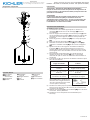
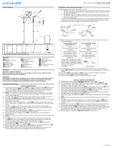
Diagrama de Accesorios
Lista de Partes
[A] La Cadena
[B] Anillo
Decorativo
[C] Artefacto
[D] Escudete
[E] La Arandela de
Seguridad
[F] La Tuerca
Hexagonal
[G] Abrazadera de
Montaje
[H] Los Tornillos
de Montaje
[I] Caja de
Distribución
Eléctrica
[J] Las Perillas
[K] LasAarandelas
de Seguridad
Precauciones
PRECAUCIÓN – RIESGO DE DESCARGA ELÉCTRICA –
Desconecte la electricidad en el panel principal del
interruptor automáco o caja principal de fusibles antes de
comenzar y durante la instalación.
ADVERTENCIA:
Este accesorio está desnado a la instalación de
acuerdo con el Naonal Electrical Code (NEC) y todas las
especicaciones del código local. Si no está familiarizado
con los requisitos del código, la instalación se recomienda
un electricista cercado.
Instrucciones de Instalación
CADENA COLGADA
1) Encuentre los oricios roscados adecuados en la
abrazadera de montaje [G]. Fije los tornillos de montaje
[H] en los oricios roscados.
2) Fije la abrazadera de montaje a la caja de distribución
eléctrica [I] ulizando los tornillos de montaje [L]
suministrados. La abrazadera de montaje se puede
ajustar para adaptarse a la posición del artefacto.
3) Coloque la moldura metálica [M] en la parte superior del
cuerpo principal [C].
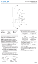
I
G
L
E
F
H
D
K
J
B
A
B
C
M

IS-42496-CB
We’re here to help 866-558-5706
Hrs: M-F 9am to 5pm EST
6) Adjust chain to desired length at this me and aach
chain[A] to decorave loops by opening one chain
link, close the open links by wrapping with a towel and
squeezing closed using pliers.
7) Weave electrical wire and ground wire through chain
links no more than 3 inches apart and run into the
canopy.
8) Grounding instrucons: (See Illus. a or b).
a) On xtures where mounng strap is provided with a
hole and two raised dimples, wrap ground wire from
outlet box around green ground screw, and thread
into hole.
b) On xtures where a cupped washer is provided,
aach ground wire from outlet box under cupped
washer and green ground screw, and thread into
mounng strap.
If xture is provided with ground wire, connect xture
ground wire to outlet box ground wire with wire
connector (Not provided) aer following the above steps.
Never connect ground wire to black or white power
supply wires.
9) Make wire connecon. Reference chart below for correct
connecons and wire accordingly.
Connect Black or Red
Supply Wire to:
Connect White Supply
Wire to:
Black White
*Parallel cord (round &
smooth)
*Parallel cord (square &
ridged)
Clear, Brown, Gold or
Black without Tracer
Clear, Brown, Gold or Black
with Tracer
Insulated wire (other
than green) with copper
conductor
Insulated wire (other
than green) with silver
conductor
*Note: When parallel wire (SPT
1 & SPT 2) are used. The neutral
wire is square shaped or ridged
and the other wire will be round
in shape or smooth (See illus.)
Neutral Wire
10) Raise canopy to ceiling. Note: Be certain wires do not
get pinched between the canopy and ceiling.
11) Use knobs[J] and lockwashers[K] to secure canopy.
Tighten to secure.
12) Insert recommended bulbs (Not supplied).
GREEN GROUND
SCREW
CUPPED
WASHER
OUTLET BOX
GROUND
FIXTURE
GROUND
DIMPLES
WIRE CONNECTOR
OUTLET BOX
GROUND
GREEN GROUND
SCREW
FIXTURE
GROUND
a
b
Fixture Diagram
Parts List
[A] Chain
[B] Decorative
Loop
[C] Main Body
[D] Canopy
[E] Lockwasher
[F] Hexnut
[G] Mounting
Strap
[H] Mounting
Screws
[I] Outlet Box
[J] Knobs
[K] Lockwashers
[L] Strap
Mounting
Screws
[M] Metal Trim
Cauons
CAUTION – RISK OF SHOCK –
Disconnect Power at the main circuit breaker panel or main
fusebox before starng and during the installaon.
WARNING:
This xture is intended for installaon in accordance
with the Naonal Electrical Code (NEC) and all local code
specicaons. If you are not familiar with code requirements,
installaon by a cered electrician is recommended.
Installaon Instrucons
1) Find the appropriate threaded holes on mounng
strap[G]. Assemble mounng screws[H] into threaded
holes.
2) Aach mounng strap to outlet box[I] using the supplied
strap mounng screws[L]. The mounng strap can be
adjusted to suit posion of xture.
3) Place the metal trim[M] on top of the main body[C].
4) Aach one decorave loop[B] to xture.
5) Aach the other decorave loop[B] to the canopy[D]
using the lockwasher[E] and the hexnut[F].
I
G
L
E
F
H
D
K
J
B
A
B
C
M

IS-42496-CB
Nous sommes là pour vous aider 866-558-5706
Heures : du lundi au vendredi, de 9h à 17h (heure de l’Est)
INSTRUCTIONS:
For Assembling and Installing Fixtures in Canada
Pour L’assemblage et L’installaon Au Canada
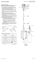
SUSPENDU AVEC CHAÎNE :
1) Localisez les trous letés appropriés sur l’étrier de
montage [G]. Vissez les vis de montage [H] dans les
trous letés.
2) Fixez le support de montage sur la boîte à prises [I] avec
les vis de xaon du support [l] (fournies). Le support de
montage peut être réglé en foncon de la posion du
luminaire.
3) Placez la garniture métallique [M] sur le corps principal
[C].
4) Fixez une boucle décorave [B] à la xaon [C].
5) Aachez l’autre boucle décorave [B] au cache [D] à
l’aide de la rondelle d’arrêt [E] et de l’écrou hexagonal
[F].
6) Ajustez la chaîne à la longueur souhaitée et aachez
la chaîne [A] aux boucles décoraves en ouvrant un
maillon de la chaîne, fermez les maillons ouverts en les
enveloppant avec une serviee et en les serrant à l’aide
d’une pince.
7) Passez d’abord le l électrique et le l de terre d’un
maillon à l’autre de la chaîne [H] avec un intervalle
maximal de 7,50 cm entre et acheminez ensuite dans le
couvercle.
8) Connecter les ls. Se reporter au tableau ci-dessous pour
faire les connexions.
Connecter le l noir ou
rouge de la boite
Connecter le l blanc de
la boîte
A Noir A Blanc
*Au cordon parallèle (rond
et lisse)
*Au cordon parallèle (à
angles droits el strié)
Au transparent, doré,
marron, ou noir sans l
disncf
Au transparent, doré,
marron, ou noir avec un l
disncf
Fil isolé (sauf l vert) avec
conducteur en cuivre
Fil isolé (sauf l vert) avec
conducteur en argent
*Remarque: Avec emploi d’un
l paralléle (SPT 1 et SPT 2). Le
l neutre est á angles droits ou
strié et l’autre l doit étre rond
ou lisse (Voir le schéma).
Fil Neutre
9) Soulevez le cache jusqu’au plafond. REMARQUE :
Assurez-vous que certains ls ne sont pas coincés entre
le cache et le plafond.
10) Ulisez les boutons [J] et les rondelles [K] pour sécuriser
le couvert. Serrez pour xer.
11) Installez la ou les ampoules recommandées (non
fournies).
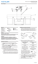
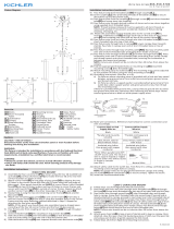
Diagramme d’appareils
ATTENTION – RISQUE DE DÉCHARGES ÉLECTRIQUES -
Couper le courant au niveau du panneau du disjoncteur du
circuit principal ou de la boîte à fusibles principale avant de
procéder à l’installaon.
ATTENTION:
Ce luminaire doit être installé conformément aux codes
d’électricité naonaux (NEC) et sasfaire toutes les
spécicaons des codes locaux. Si vous ne connaissez pas
les exigences de ces codes, il est recommandé de coner
l’installaon à un électricien ceré.
Liste des Pièces
Précauons
[A] La chaîne
[B] Boucle
décorave
[C] La xaon
[D] Cache
[E] Rondelle
d’arrêt
[F] Bague Filetée
[G] Vis
[H] Chaîne
[I] la boîte à
prises
[J] Les boutons
[K] Les rondelles
Instrucons d’installaon
I
G
L
E
F
H
D
K
J
B
A
B
C
M
-
 1
1
-
 2
2
-
 3
3
-
 4
4


Kichler Lighting 42496NI Manual de usuario
- Tipo
- Manual de usuario
- Este manual también es adecuado para
en otros idiomas
- français: Kichler Lighting 42496NI Manuel utilisateur
- English: Kichler Lighting 42496NI User manual
Artículos relacionados
-
 Kichler Lighting 44293WWW Manual de usuario
-
 Kichler Lighting 49987DBK Manual de usuario
-
 Kichler Lighting 42497NI Manual de usuario
-
 Kichler Lighting 44287WWW Manual de usuario
-
 Kichler Lighting 43898OZ Manual de usuario
-
 Kichler Lighting 49791AUB Manual de usuario
-
 Kichler Lighting 52283NI Manual de usuario
-
 Kichler Lighting 49309BK Manual de usuario
-
 Kichler Lighting 52024CH Manual de usuario
-
 Kichler Lighting 42494CH Manual de usuario


