Smarter Tools ST-GP4750EB El manual del propietario
- Categoría
- Generadores de poder
- Tipo
- El manual del propietario


ii
©2013 Smarter Tools, Inc. All Rights Reserved
Record the model and serial numbers as well as date and place of purchase for future reference.
Have this information available when ordering parts and when making technical or warranty inquiries.
Smarter Tools Customer Service
1-888-241-8498
Model Number
GP-4750 (E, EB)
Serial Number
Date of Purchase
Purchase Location

iii
©2013 Smarter Tools, Inc. All Rights Reserved
Notes
________________________________________________
________________________________________________
________________________________________________
________________________________________________
________________________________________________
________________________________________________
________________________________________________
________________________________________________
________________________________________________
________________________________________________
________________________________________________
________________________________________________
________________________________________________
________________________________________________
________________________________________________
________________________________________________
________________________________________________
________________________________________________
________________________________________________
________________________________________________
________________________________________________
________________________________________________
________________________________________________
________________________________________________

iv
©2013 Smarter Tools, Inc. All Rights Reserved
Specifications
_________________________________________________________________________________________________
ST-GP4750EB
Engine Type 4-Stroke OHV Air Cooled Single Cylinder CARB Certified
Horsepower 7
Engine Displacement (cc) 208
Running Watts 3600w
Starting Watts 4750w
Rated Frequency 60HZ
Rated Voltage 120V
Rated Current 30A
Run Time 10hrs at 50% load
Receptacles (qty.) (2) 120V AC 20A; (1) 120V 30A RV, (1) 120V 30A AC, (1) 12V 8A DC
Net/Gross Weight 92/105lbs.
Noise Level (dB) 72dB
Fuel Type Unleaded gasoline
Fuel Capacity (gal.) 4
Fuel Gauge Yes
Oil Type SAE 10W-30 (20 oz, .62 Qt.)
Start Type Electric/Recoil
AC Volt Meter Yes
Frame Construction Tubular Steel
Wheel & Handle Kit 7” No Flat wheels and Handle kit included
Assembled Dimensions
L x W x H (in.)
24.5"x20.5"x20.5"

v
©2013 Smarter Tools, Inc. All Rights Reserved
Controls and Features
_________________________________________________________________________________________________
Familiarize yourself with the location and function of the controls and features before operating your generator. Save this
manual for future reference.
Generator
1. Fuel Gauge – Indicates amount of fuel in tank.
2. Fuel Tank – 4 gallon capacity
3. Choke – Used to start engine.
4. Fuel Valve – Turn this valve to the on position to supply fuel to the engine
5. Air Filter – Protects the engine by filtering dust and debris from the intake air.
6. Recoil Starter – Used to start the engine.
7. Low Oil Shutdown – Senses the level of oil in the crankcase and shuts the engine down if the level falls too low.
8. Oil Filler Cap/Dipstick – Used to check and fill engine oil.
9. Control Panel – See “Control Panel” on page vi

vi
©2013 Smarter Tools, Inc. All Rights Reserved
Controls and Features (cont’d)
_________________________________________________________________________________________________
Control Panel
1. Engine Switch – Used to turn on and off the
engine. For electric models, it is also used to
start the engine.
2. Digital Running Hours/Voltage/Hertz Meter –
Displays the number of hours the engine has
run, voltage used, and hertz used.
3. Circuit Breakers – Protects the generator
against electrical overload.
4. 120V 20A Duplex – This duplex is protected by
a 20A circuit breaker. Use this duplex to operate
120 volt AC, single phase, 60 Hz loads requiring
up to 20 A or 2400 Watts of power.
5. 120V 30A Twist-Lock – This receptacle powers
120 Volt AC, 60 Hz, single phase loads requiring
up to 30A or 3600 Watts of power.
.
6. 120V 30A RV Outlet– This receptacle powers a
RV with 120 Volt AC, 60 Hz, single phase loads
requiring up to 30A or 3600 Watts of power.
7. 12V DC Connector – Used to charge 12V DC
batteries.
8. General Specifications
9. Ground Terminal – Consult an electrician for
local grounding regulations.
.

©2013 Smarter Tools, Inc. All Rights Reserved
Table of Contents
Introduction .............................................................. 02
Warranty Identification ............................................ 03
Limited Warranty ...................................................... 04
Safety Guidelines – Definitions .............................. 05
General Precautions ................................................ 06
Carbon Monoxide .......................................... 06
Gasoline and Oil ............................................ 06
Hot Components ........................................... 07
Power Output ................................................ 07
Work Area ..................................................... 07
Electrical Safety ............................................ 08
Personal Safety ............................................. 08
General Use and Care .................................. 09
Servicing........................................................ 09
Installation ..................................................... 10
Mechanical .................................................... 10
Chemicals...................................................... 11
Noise ............................................................. 11
Extension Cords ............................................ 11
Installation ................................................................ 12
General Location ........................................... 12
Wheel and Handle Kit Installation ................. 13
Support and Mounting ................................... 13
Grounding...................................................... 13
Connect the Battery ...................................... 14
Add Engine Oil .............................................. 14
Add Fuel ........................................................ 15
Operation .................................................................. 16
Starting .......................................................... 16
Surge Protection ........................................... 16
Capacity ........................................................ 17
Power Management ...................................... 18
Connecting Electrical Loads.......................... 18
Stopping the Engine ...................................... 18
Wattage Reference Guide ........................................ 19
Your Power Needs ......................................... 19
Inspection, Cleaning, and Maintenance ................. 20
Changing Oil .................................................. 20
Spark Plug ..................................................... 21
Air Filter .......................................................... 21
Spark Arrester (optional) ................................ 22
Cleaning ......................................................... 22
Maintenance Schedule .................................. 22
Storage .......................................................... 23
Transporting ................................................... 23
Troubleshooting ........................................................ 24
Wiring Diagram ......................................................... 25
Parts Lists .................................................................. 26
Crankcase Assembly ..................................... 26
Intake & Exhaust Mechanism ........................ 26
Cylinder Head Assembly ............................... 27
Generator Assembly ...................................... 28
Crankshaft Assembly ..................................... 28
Starter Assembly............................................ 29
Electric Starter Assembly ............................... 29
Ignition Assembly ........................................... 30
Centrifugal Timing Implement Assembly ....... 30
Carburetor Assembly ..................................... 30
Air Cleaner Assembly .................................... 31
Gas Tank ....................................................... 31
Control Panel Assembly ................................ 32
Exhalation System ......................................... 32
Muffler ............................................................ 33
Frame Assembly ............................................ 33

GP Series
2
©2013 Smarter Tools, Inc. All Rights Reserved
Introduction
_________________________________________________________________________________________________
Congratulations on your purchase of a Smarter Tools generator. Smarter Tools designs and builds generators to strict
specifications. With proper use and maintenance, this generator will bring years of satisfying service.
Portable Power Generator
This unit is an electric start, gasoline engine driven, alternating current (AC) generator. It is designed to supply electrical
power for lighting, appliances, tools and similar equipment.
This Booklet
Every effort has been made to ensure the accuracy and completeness of the information in this manual.
We reserve the right to change, alter and/or improve the product and this document at any time without prior notice. For the
most up to date information regarding your Smarter Tools product please visit us at usesmartertools.com
WARNING!
READ AND UNDERSTAND ALL SAFETY PRECAUTIONS IN THIS MANUAL BEFORE OPERATING.
FAILURE TO COMPLY WITH INSTRUCTIONS IN THIS MANUAL COULD RESULT IN PERSONAL
INJURY, PROPERTY DAMAGE, AND/ OR VOIDING OF YOUR WARRANTY. SMARTER TOOLS WILL
NOT BE LIABLE FOR ANY DAMAGE BECAUSE OF FAILURE TO FOLLOW THESE INSTRUCTIONS.

GP Series
3
©2013 Smarter Tools, Inc. All Rights Reserved
Warranty Identification
_________________________________________________________________________________________________
To assist in accurately determining whether your Smarter Tools product is still covered by manufacturer’s warranty and to
identify your product properly should you need to contact customer service an Hour Meter and Identification Plate have
been installed.
Hour Meter
The product’s Hour Meter can be found on the front control panel to the right of the power switch.
Note: The Hour Meter is tied directly to the product warranty. Attempting to disable or otherwise tamper with
the Hour Meter will VOID the manufacturer’s warranty.
Identification Plate
The product’s Identification Plate can be found on the lower-frame cross arm just behind the air filter. See figure below.
Note: Properly registering your product with Smarter Tools is the only way to ensure that your product will
be eligible for warranty replacement or repair should an unforeseen event cause the Identification Plate to
be unreadable. Register your product online at usesmartertools.com/register or by mailing in your warranty
registration card within 14 days or product purchase.

GP Series
4
©2013 Smarter Tools, Inc. All Rights Reserved
LIMITED WARRANTY
_________________________________________________________________________________________________
Effective May 1, 2013. Replaces all undated warranties and all warranties
dated before May 1, 2013
Warranty Qualifications
Smarter Tools will register this warranty upon receipt of
your Warranty Registration Card and a copy of your
sales receipt from one of Smarter Tools' retail locations
as proof of purchase.
Please submit your warranty registration and your proof
of purchase within fourteen (14) days of the date of
purchase.
Repair/Replacement Warranty
Smarter Tools warrants to the original purchaser that the
mechanical and electrical components will be free of
defects in material and workmanship for a period of two
(2) year or 200 hours (measured by the factory installed
hour meter) from the original date of purchase (90 days
or 200 hours for commercial & industrial use).
Transportation charges on product submitted for repair or
replacement under this warranty are the sole
responsibility of the purchaser. This workmanship for a
period of warranty only applies to the original purchaser
and is not transferable.
Do not return the unit to the place of
purchase
Contact Smarter Tools’ Customer Service and Smarter
Tools will troubleshoot any issue via phone or e-mail. If
the problem is not corrected by this method, Smarter
Tools will, at its option, authorize evaluation, repair or
replacement of the defective part or component at a
Smarter Tools Service Center. Smarter Tools will provide
you with a case number for warranty service. Please
keep it for future reference. Repairs or replacements
without prior authorization, or at an unauthorized repair
facility, will not be covered.
Warranty Exclusions
This warranty does not cover the following repairs and
equipment:
Normal Wear
Generators need periodic parts and service to
perform well. This warranty does not cover repair
when normal use has exhausted the life of a part
or the equipment as a whole.
Installation, Use and Maintenance
This warranty will not apply to parts and/or labor
if this generator is deemed to have been
misused, neglected, involved in an accident,
abused, loaded beyond the generator's limits,
modified, installed improperly or connected
incorrectly to any electrical component. Normal
maintenance such as spark plugs, air filters,
adjustments, fuel system cleaning and
obstruction due to buildup is not covered by this
warranty.
Other Exclusions
This warranty excludes:
• Merchandise sold as reconditioned, used as
rental equipment, or floor/display models sold
without packaging and/or missing parts or
components.
• Repair and transportation costs of merchandise
determined not to be defective.
• Cosmetic defects such as paint, decals, etc.
• Wear items such as filter elements, o-rings, etc.
• Accessory parts such as starting batteries, and
storage covers.
• Failures due to acts of God and other forces of
nature beyond the manufacturer's control.
• Problems caused by parts that are not original
Smarter Tools parts.
This warranty does not apply to generators used
for prime power in place of a utility.
Limits of Implied Warranty and
Consequential Damage
Smarter Tools disclaims any obligation to cover any loss
of time, use of this product, freight, or any incidental or
consequential claim by anyone from using this generator.
THIS WARRANTY IS IN LIEU OF ALL OTHER
WARRANTIES, EXPRESS OR IMPLIED, INCLUDING
WARRANTIES OF MERCHANTABILITY OR FITNESS
FOR A PARTICULAR PURPOSE.
A unit provided as an exchange will be subject to the
warranty of the original unit. The length of the warranty
governing the exchanged unit will remain calculated by
reference to the purchase date of the original unit.
This warranty gives you certain legal rights which may
change from state to state. Your state may also have
other rights you may be entitled to that are not listed
within this warranty.
Some states do not allow the exclusion, so it may not
apply to you.
Contact us at:
Smarter Tools Customer Service
12195 Harley Club Drive
Ashland, VA 23005
(804)798-8588
customerservice@usesmartertools.com

GP Series
5
©2013 Smarter Tools, Inc. All Rights Reserved
Owner’s Manual
Safety Guidelines - Definitions
______________________________________________________________________________________________
This manual contains important information that you need to know and understand in order to assure YOUR SAFETY and
PROPER OPERATION OF EQUIPMENT. The following symbols help you recognize this information. Please read the
manual and pay attention to these sections.
Save These Important Safety Instructions!
Read and understand all of these safety instructions. Be sure to retain them for future use.
WARNING!
WARNINGS INDICATE A CERTAINTY OR STRONG POSSIBILITY OF PERSONAL INJURY OR
DEATH IF INSTRUCTIONS ARE NOT FOLLOWED.
CAUTION:
CAUTIONS INDICATE A POSSIBILITY OF EQUIPMENT DAMAGE IF INSTRUCTIONS ARE NOT
FOLLOWED PROPERLY.
Note: Notes give helpful information.
WARNING!
IMPROPER OPERATION OR MAINTENANCE OF THIS PRODUCT COULD RESULT IN SERIOUS
INJURY AND PROPERTY DAMAGE. READ AND UNDERSTAND ALL WARNINGS AND OPERATING
INSTRUCTIONS BEFORE USING THIS EQUIPMENT. BASIC SAFETY PRECAUTIONS SHOULD
ALWAYS BE FOLLOWED TO REDUCE THE RISK OF PERSONAL INJURY.
Save These Important Safety Instructions!
Read and understand all of these safety instructions. Be sure to retain them for future use.

GP Series
6
©2013 Smarter Tools, Inc. All Rights Reserved
General Safety Precautions
______________________________________________________________________________________________
WARNING!
FAILURE TO FOLLOW THESE INSTRUCTIONS CAN RESULT IN SEVERE INJURY OR DEATH.
CAUTION:
FAILURE TO FOLLOW THESE INSTRUCTIONS CAN ALSO RESULT IN DAMAGE TO THE EQUIPMENT
AND/OR THE ITEM YOU ARE WORKING ON OR WITH.
Carbon Monoxide
• Carbon Monoxide is an odorless and colorless gas. Breathing exhaust that contains this poisonous gas can cause
unconsciousness and may lead to death.
• The engine exhaust from this product contains chemicals recognized by the state of California to cause cancer,
birth defects, or other reproductive harm.
• When this tool is running, ensure that the area is well ventilated. Never run the engine in an enclosed area. Run
the engine in an open area or with an exhaust evacuation system in an enclosed area.
• NEVER use a generator inside homes, garages, crawlspaces, or other partially enclosed areas. Deadly levels of
carbon monoxide can build up in these areas. Using a fan or opening windows and doors does NOT supply
enough fresh air.
• ONLY use a generator outdoors and far away from open windows, doors, and vents. These openings can pull in
generator exhaust.
• Even when you use a generator correctly, CO may leak into the home. ALWAYS use a battery-powered or
battery-backup CO alarm in the home.
• If you start to feel sick, dizzy, or weak after the generator has been running, move to fresh air RIGHT AWAY. See
a doctor. You could have carbon monoxide poisoning.
WARNING!
THE EXHAUST CONTAINS POISONOUS CARBON MONOXIDE GAS THAT CAN CAUSE LOSS OF
CONSCIOUSNESS AND MAY LEAD TO DEATH.
Gasoline and Oil
This product requires oil and fuel. THE ENGINE WILL NOT START WITHOUT OIL. Work in well ventilated area. Keep
cigarettes, flames or sparks away from the work area or where gasoline is stored.
WARNING!
GASOLINE IS EXTREMELY FLAMMABLE AND IS EXPLOSIVE UNDER CERTAIN CONDITIONS. KEEP
OUT OF REACH OF CHILDREN.

GP Series
7
©2013 Smarter Tools, Inc. All Rights Reserved
General Safety Precautions (cont’d)
______________________________________________________________________________________________
Gasoline and Oil (cont’d)
• Gasoline fuel and fumes are flammable and potentially explosive. Use proper fuel storage and handling
procedures. Always have multiple ABC class fire extinguishers nearby.
• Keep the generator and surrounding area clean at all times. Keep the generator at least 5 feet away from
buildings and other equipment during operation.
• Fuel or oil spills must be cleaned up immediately. Dispose of fluids and cleaning materials as per any local, state,
or federal codes and regulations. Store oily rags in a covered metal container.
• Never store fuel or other flammable materials near the generator.
• Do not smoke, or allow sparks, flames or other sources of ignition around the engine and fuel tank. Fuel vapors
are explosive.
• Keep grounded conductive objects, such as tools, away from exposed, live electrical parts and connections to
avoid sparking or arcing. These events could ignite fumes or vapors.
• Do not refill the fuel tank while the engine is running or while the engine is still hot. Do not operate the generator
with known leaks in the fuel system.
• Excessive buildup of unburned fuel gases in the exhaust system can create a potentially explosive condition. This
buildup can occur after repeated failed start attempts, valve testing, or hot engine shutdown. If this occurs, open
exhaust system drain plugs, if equipped, and allow the gases to dissipate before attempting to restart the generator.
• Use only engine manufacturer recommended fuel and oil.
Hot Components
WARNING!
HOT EXHAUST CAN BURN YOU. ENGINE AND EXHAUST SYSTEM PARTS BECOME VERY HOT AND
REMAIN HOT FOR SOME TIME AFTER THE ENGINE IS RUN. WEAR INSULATED GLOVES OR WAIT
UNTIL THE ENGINE AND EXHAUST SYSTEM HAVE COOLED BEFORE HANDLING THESE PARTS.
Power Output
This generator is not designed to power sensitive electronic equipment (including computers and medical devices) without
the addition of an approved line conditioner, which is sold separately.
CAUTION:
ATTEMPTING TO POWER SENSITIVE ELECTRONIC EQUIPMENT WITHOUT THE USE OF AN
APPROVED LINE CONDITIONER MAY CAUSE DAMAGE TO THE EQUIPMENT.
Work Area
• Keep your work area clean and well lit. Cluttered benches and dark areas invite accidents.
• Do not operate power tools in explosive atmospheres, such as in the presence of flammable liquids, gases, or
dust. Generators create sparks which may ignite the dust or fumes.
• Keep bystanders, children, and visitors away while operating a generator. Provide barriers or shields as needed.

GP Series
8
©2013 Smarter Tools, Inc. All Rights Reserved
General Safety Precautions (cont’d)
______________________________________________________________________________________________
Electrical Safety
• Keep all electrical equipment clean and dry. Replace any wiring where the insulation is cracked, cut eroded part
or otherwise degraded. Replace terminals that are worn, discolored, or corroded. Keep terminals clean and tight.
• Insulate all connections and disconnected wires.
• Do not abuse the power cord. Keep power cords away from heat, oil, sharp edges, or moving parts. Replace
damaged power cords immediately. Damaged power cords increase the risk of electric shock.
• Do not operate the generator with wet hands. Do not expose generator to rain, snow or wet conditions. Water will
increase the risk of electric shock. The generator is a potential source of electrical shock if not kept dry.
• Do not attempt to connect or disconnect load connections while standing in water, or on wet or soggy ground.
• Do not touch electrically energized parts of the generator and interconnecting cables or conductors with any part
of the body, or with any non-insulated conductive object.
• Avoid body contact with grounded surfaces such as pipes, radiators, ranges, and refrigerators. There is an
increased risk of electric shock if your body is grounded.
• When operating a power tool outside, use an outdoor extension cord marked “W-A” or “W”. These extension
cords are rated for outdoor use, and reduce the risk of electric shock.
• Grounded tools must be plugged into an outlet properly installed and grounded in accordance with all codes and
ordinances. Never remove the grounding prong or modify the plug in any way. Do not use any adapter plugs.
• Double insulated tools are equipped with a polarized plug where one blade is wider than the other. This plug fits in
a polarized outlet only one way. If the plug does not fit fully in the outlet, reverse the plug. If it still does not fit,
contact a qualified electrician to install a polarized outlet. Do not change the plug in any way. Double insulation
eliminates the need for the three-wire grounded power cord and grounded power supply system.
• Before servicing equipment powered by the generator, disconnect the equipment from its power input.
• The generator must be earth-grounded for fixed installations in accordance with all relevant electrical codes and
standards before operation.
• Grounding provides a low-resistance path to carry electricity away from the user in the event of an electrical
malfunction.
• All connections and conduits from the generator to the load must only be installed by trained and licensed
electricians and in compliance with all relevant local, state, and federal electrical codes and standards, and other
regulations where applicable.
• Connect the generator only to a load or electrical system (110/120 volt) that is compatible with the electrical
characteristics and rated capacities of the generator.
• NEVER try to power building or home wiring by plugging the generator into a wall outlet, a practice known as
“backfeeding.” This is extremely dangerous and presents an electrocution risk to utility workers and neighbors
served by the same utility transformer. It also bypasses some of the built-in household circuit protection devices.
Personal Safety
CAUTION:
DO NOT SIT, STAND, OR PLACE OBJECTS ON TOP OF THE GENERATORS FUEL TANK.
REGARDLESS OF WHETHER IT IS RUNNING OR NOT.
• Stay alert. Watch what you are doing, and use common sense when operating a generator. Do not use generator
while tired or under the influence of drugs, alcohol, or medication. A moment of inattention while operating
generators may result in serious personal injury.
• Make note of the location of the engine power switch should you need to turn off the generator quickly.
• Dress properly. Contain long hair, clothing, jewelry, and gloves as they can be caught in moving parts.
• Avoid accidental starting. Make sure the power switch is in its “OFF” position, and disconnect the spark plug wire
when not in use.

GP Series
9
©2013 Smarter Tools, Inc. All Rights Reserved
General Safety Precautions (cont’d)
______________________________________________________________________________________________
Personal Safety (cont’d)
• Remove adjusting keys or wrenches before turning the generator on. A wrench or a key that is left attached to a
rotating part of the generator may result in personal injury.
• Do not overreach. Keep proper footing and balance at all times.
• Use safety equipment. Always wear eye protection. Wear ANSI approved safety impact eye goggles. Dust mask, non-
skid safety shoes, safety gloves, hard hat, or hearing protection must be used for appropriate conditions.
• Do not use the generator if the power switch does not turn it on or off. Any generator that
cannot be controlled with the power switch is dangerous and must be replaced.
• Do not force the generator. Use the correct generator for your application. The correct
generator will do the job better and safer at the rate for which it is designed.
• The generator is extremely heavy. Two or more people should assist when moving or lifting this product. Never lift the
Generator using the engine or alternator lifting lugs. Connect lifting equipment to the Frame of the generator.
Generator Use and Care
• Make sure the power switch is in its “OFF” position and disconnect the spark plug wire before making any adjustment,
changing accessories, or storing the generator. Such preventive safety measures reduce the risk of starting the
generator accidentally.
• Store idle generators out of reach of children and other untrained persons. Generators are dangerous in the hands of
untrained users.
• Maintain generators with care. Do not use a damaged generator. Tag damaged generators “Do not use” until
repaired.
• Check for misalignment or binding of moving parts, breakage of parts, and any other condition that may affect the
generator’s operation. If damaged, have the generator serviced before using. Many accidents are caused by poorly
maintained generators.
• Use only accessories that are recommended by the manufacturer for your model. Accessories that may be suitable
for one generator may become hazardous when used on another generator.
Servicing
• Maintain labels and name plates on the generator and engine. These carry important information. If unreadable or
missing, contact Smarter Tools immediately for a replacement.
• Generator service must be performed only by qualified repair personnel. Service or maintenance performed by
unqualified personnel could result in a risk of injury.
• When servicing a generator, use only identical replacement parts. Follow all appropriate instructions in this manual.
Use of unauthorized parts or failure to follow maintenance instructions may create a risk of electric shock or injury.
WARNING!
PEOPLE WITH PACEMAKERS SHOULD CONSULT THEIR PHYSICIAN(S) BEFORE USING THIS
PRODUCT. ELECTROMAGNETIC FIELDS IN CLOSE PROXIMITY TO A HEART PACEMAKER COULD
CAUSE INTERFERENCE TO OR FAILURE OF THE PACEMAKER.

GP Series
10
©2013 Smarter Tools, Inc. All Rights Reserved
General Safety Precautions (cont’d)
______________________________________________________________________________________________
Installation
• Ensure installation meets all applicable safety, and local and national electrical codes. Have installation performed
by a qualified, licensed electrician and building contractor.
• All electrical work, including the earth-ground connection, should be completed by a licensed electrician.
• Any separate fuel storage or generator supply facility must be built or installed in full compliance with all relevant
local, state, and federal regulations.
• It is recommended to use the generator only in well ventilated outdoor areas. A running gasoline engine will
generate carbon monoxide, a colorless, odorless gas that, if inhaled, can cause serious injury or death. If the
generator is installed indoors, exhaust fumes must be piped out of the building using leak-free, heat resistant
piping. Pipes and silencer should not use any flammable materials, nor should they be installed near the same.
Generator exhaust fumes must be within legal limits and installation must always meet local building codes.
• If the generator is installed outdoors, it must be weatherproofed and should be soundproofed. It should not be run
outdoors without protection of the generator and wiring conduit.
• Two or more people should assist when moving or lifting this product. Never lift the Generator using the engine or
alternator lifting lugs. Connect lifting equipment to the Frame of the generator.
• Before lifting the generator, ensure the lift rigging and supporting structure are in good condition, and are rated to
lift such a load.
• Keep all personnel away from the suspended generator during relocating.
• The supporting floor/ground surface should be level, and strong enough to safely hold the weight of the generator.
If the floor/grounded surface is not level, strong cross members should be placed under the full length of the
generator frame at its low side.
• For trailer installation, the generator should be mounted on the center point of the trailer, over the wheels. The
trailer must be capable of supporting the weight of the generator and all contents (tools, etc.)
• Install sound-and weather-proofing only when it is not raining or snowing to avoid trapping moisture within the
generator’s area.
Mechanical
• Always make sure the power switch is in its “OFF” position. Disconnect the spark plug wire, and allow the engine
to completely cool before carrying out maintenance.
• Check for damaged parts. Before using the generator, any part that appears damaged should be carefully
checked to determine that it will operate properly and perform its intended function. Check for alignment and
binding of moving parts, any broken parts or mounting fixtures, and any other condition that may affect proper
operation technician.
• The generator is designed with guards for protection from moving parts. In any case, care must still be taken to
protect personnel and equipment from other mechanical hazards when working around the generator.
• Do not operate the generator with safety guards removed. While the generator is running, do not attempt to reach
around the safety guard for maintenance or any other reason.
• Keep hands, arms, long hair, loose clothing, and jewelry away from moving parts. Be aware that when engine
parts are moving fast they cannot be seen clearly.
• Keep access doors on enclosures closed and locked when access is not required.
• When working on or around the generator always wear protective clothing including ANSI approved safety gloves,
safety eye goggles, and safety hat.
• Do not alter or adjust any part of the generator that is assembled and supplied by the manufacturer.
• Always follow and complete scheduled engine and generator maintenance.

GP Series
11
©2013 Smarter Tools, Inc. All Rights Reserved
General Safety Precautions (cont’d)
______________________________________________________________________________________________
Chemicals
• Avoid contact with hot fuel, oil, exhaust fumes, and hot solid surfaces.
• Avoid body contact with fuels, oils, and lubricants used in the generator. If swallowed, seek medical treatment
immediately. Do not induce vomiting if fuel is swallowed. For skin contact, immediately wash with soap and water.
For eye contact, immediately flush eyes with clean water and seek medical attention.
Noise
Prolonged exposure to noise levels above 85dBA is hazardous to hearing.
Always wear ANSI approved ear protection when operating or working around the Generator when it is running.
Extension Cords
If an extension cord (not included) is used, make sure to use only UL approved cords having the correct gauge and length
according to the following table:
Nameplate Amps Cord Lengths
(@full load)
0’-50’ 50’-100’ 100’-150’ 150’-200’
0-5
16
16
12
12
5.1-8
16
14
10
-
8.1-12 14 12 - -
12.1-15 12 10 - -
15-20 10 10 - -

GP Series
12
©2013 Smarter Tools, Inc. All Rights Reserved
Installation
____________________________________________________________________________________________
Note: Prior to powering tools and equipment, make sure the generator’s rated voltage, wattage, and
amperage capacity (See specification sheet) is adequate to supply all electrical loads that the unit will power.
If powering exceeds the generator’s capacity, it may be necessary to group one or more of the tools and/or
equipment for connection to a separate generator.
Electrical and other permits may be required for the installation of emergency power systems. Investigate your local
building and electrical codes before installing this unit. Installation must be completed by licensed contractors.
WARNING!
THE GENERATOR IS EXTREMELY HEAVY. USE CARE AND THE PROPER LIFTING OR HOISTING
EQUIPMENT WHEN MOVING IT TO THE INSTALLATION LOCATION.
ALWAYS CONNECT HOSE LINES TO THE FRAME OF THE GENERATOR.
CAUTION:
DO NOT ADD OIL OR GASOLINE UNTIL INSTALLATION IS COMPLETE.
General Location
CAUTION:
GENERATOR SHOULD ONLY BE OPERATED ON A LEVEL SERVICE. DO NOT OPERATE GENERATOR
ON LOOSE GROUND OR OBVIOUS INCLINES. THE LOW OIL SHUT DOWN FEATURE MAY BE
PREMATURELY ACTIVATED IN THESE CASES CAUSING THE UNIT TO NOT START.
• Make sure to locate and install the generator outdoors where cooling air is readily available.
• Install the generator so that the air inlets and outlets are not blocked by obstructions such as bushes, trees, or
snow drifts. Locating it in the path of heavy winds or snowdrifts may require the placement of a barrier for
protection. In normal weather conditions, the air vent should face the prevailing wind direction.
• Install the generator on a concrete slab or other area where rain drainage or flood waters cannot reach it.
• Generator placement should allow four feet of access to all sides for maintenance.
• Place the generator as close as possible to the electrical tools and equipment being powered to reduce the length
of extension cords.
• If the generator in located indoors the engine exhaust must be ventilated to the outdoors using leak-proof, heat
resistant flexible metal, flex tubing.
Note: Generators used on construction sites may be subject to additional rules and regulations. If you plan
to use the generator on a construction site, please consult your local authority regarding.

GP Series
13
©2013 Smarter Tools, Inc. All Rights Reserved
Installation (cont’d)
_________________________________________________________________________________________________
Wheel and Handle Kit Installation
(Installation requires a socket wrench with 10mm, 14mm, and 17mm sockets).
1. Before adding oil or gasoline to the
engine, tip the generator slowly so that the recoil
and air filter are up.
2. Install the two wheels on the generator
using the (2) 17mm 2 ½” bolts provided.
3. Tip the generator slowly so that the recoil
and air filter are down.
4. Install the crutches on the under frame
with the (4) nuts and 14mm 1” bolts provided. On
smaller units (2) 14mm bolts are provided.
5. Tip the generator slowly so that is sits on
both the wheels and crutches.
6. Install the handles on the right side of the
frame using the (2) nuts and 10mm 1 ¾” bolts
provided.
WARNING!! TO AVOID DAMAGE
TO THE GENERATOR, REMOVE
THE BOLT AND SPACER BEFORE
USE.
Support and Mounting
Mount the generator on a concrete slab capable of supporting the weight of the generator. The slab must extend on all
sides beyond the frame by at least one foot. Contact a cement contractor for slab specifications if necessary. Attach the
frame to the concrete slab using 3/8” diameter expansion anchor bolts (not supplied).
Grounding
Note: It is recommended that only a trained and licensed electrician perform this procedure.
Connect a #6 AWG grounding wire (not included) from the ground connector on the generator to a grounding
rod (not included) that has been driven at least 24 inches deep into the earth. The grounding rod must be an
earth-driven copper or brass rod (electrode) which can adequately ground the generator.
HANDLES

GP Series
14
©2013 Smarter Tools, Inc. All Rights Reserved
Installation (cont’d)
______________________________________________________________________________________________
Note: ‘E’ and ‘EB’ models using the electric starter require a 12V battery with a minimum of 17AH. While
higher Amp Hour batteries may be used, do not attempt to start the engine using a battery rated for a lower
or higher Voltage.
Connect the Battery
For ‘E’ and ‘EB’ models only.
1. Place battery into battery cradle and secure.
2. Remove the protective cover from the positive (red) battery lead. Positive lead is marked with a “+”.
3. Attach the positive lead to the positive terminal (marked with a “+”) on the battery with the phillips-head cap screw
and secure with 8mm nut.
4. Remove the protective cover from the negative (black) battery lead. Negative lead is marked with a “-”.
5. Attach the negative lead to the negative terminal (marked with a “-”) on the battery with the phillips-head cap
screw and secure with 8mm nut.
6. The battery will charge when the generator is running with the battery cables attached.
NOTE: Connecting the battery with reverse polarity will cause damage to the generator.
DO NOT use the charging cables on the generator battery with battery cables attached.
CAUTION:
PRIOR TO FIRST USING THE GENERATOR, THE
ENGINE MUST BE FILLED WITH HIGH QUALITY SAE
10W-30 GRADE ENGINE OIL.
Add Engine Oil
1. Place the generator on a flat and level surface.
2. Remove oil fill cap/dipstick to add oil.
3. Add high quality SAE 10W-30 grade engine oil.
4. Check engine oil daily and add as needed.

GP Series
15
©2013 Smarter Tools, Inc. All Rights Reserved
Installation (cont’d)
______________________________________________________________________________________________
Add Fuel
1. Use clean, fresh, regular unleaded fuel with a minimum octane rating of 85.
2. DO NOT mix oil with fuel.
3. Clean area around the fuel cap.
4. Remove the fuel cap.
5. Be sure that the fuel strainer is in place.
6. Slowly add fuel to the tank. DO NOT overfill. Allow approximately ¼ inch of space for fuel expansion.
7. DO NOT fill above fuel strainer.
8. Screw on the fuel cap and wipe away and spilled fuel.
WARNING:
THE GENERATOR MUST BE OFF AND COOLED DOWN BEFORE REFILLING THE FUEL TANK.
Note: For DEB models read preface for propane connection and safety instructions.

GP Series
16
©2013 Smarter Tools, Inc. All Rights Reserved
Operation
______________________________________________________________________________________________
Starting
1. Make sure the generator is on a flat and level
surface.
2. Make sure the electrical powered
tools/equipment that will be used are not
plugged into the generator while the engine is
started.
3. Turn the fuel valve to the “ON” position.
4. Pull the choke rod out.
5. Turn the engine power switch to its “ON”
position.
6. For “Electric Start” models (‘E’ and ‘EB’), turn
key to the start position and hold until engine
starts. If the engine fails to start within 5
seconds, release the key and wait at least 10
seconds before attempting to start the engine
again.
7. For “Recoil Start”, hold the start handle loosely
and pull it slowly several times to allow the
gasoline to flow into the engine’s carburetor.
Then hold the start handle firmly and pull the rope
hard and fast. Pull the rope all the way out, using two
hands if necessary. If necessary pull the rope
several times until the engine starts.
1. Allow the engine to idle until warm. Then, slowly
push choke to the unchoked position. Units with the
vacuum control will automatically unchoke as the
motor warms up. Check to make sure the choke rod in
all the way.
Note: If the engine starts but does not run, make certain
that the generator is on a flat, level surface.
The engine is equipped with a low oil sensor that will
prevent the engine from running when the oil level
falls below a critical threshold.

GP Series
17
©2013 Smarter Tools, Inc. All Rights Reserved
Operation (cont’d)
______________________________________________________________________________________________
Surge Protection
CAUTION:
ATTEMPTING TO POWER SENSITIVE ELECTRONIC EQUIPMENT WITHOUT THE USE OF AN
APPROVED LINE CONDITIONER MAY CAUSE DAMAGE TO THE EQUIPMENT.
Electronic devices, including computers and many programmable appliances use components that are designed to
operate within a narrow voltage range and may be affected by momentary voltage fluctuations.
While there is no way to prevent voltage fluctuations, you can take steps to protect sensitive electronic equipment.
1. Install UL1449, CSA-listed, plug-in surge suppressors on the outlets feeding your sensitive equipment.
Surge suppressors come in single- or multi-outlet styles. They’re designed to protect against virtually all short
duration voltage fluctuations.
2. Obtain an Uninterruptible Power Supply (UPS) device. Most UPS devices come with a rechargeable battery
between the electronic equipment and power supply source. The device buffers the voltage and protects against
virtually all short duration voltage fluctuations.
Capacity
Follow these simple steps to calculate the running and starting watts necessary for your purposes.
See page 19 for Wattage Reference Guide.
1. Select the electrical devices you plan on running at the same time.
2. Total the running watts of these items. This is the amount of power you need to keep your items running.
3. Identify the highest starting wattage of all devices identified in step
a. Add this number to the number calculated in step
b. Surge wattage is the extra burst of power needed to start some electric driven equipment. Following the steps
listed under “Power Management” will guarantee that only one device will be starting at a time.

GP Series
18
©2013 Smarter Tools, Inc. All Rights Reserved
Operation (cont’d)
______________________________________________________________________________________________
Power Management
Use the following formula to convert voltage and amperage to watts:
Volts x Amps = Watts
To prolong the life of your generator and attached devices, follow these steps to add electrical load:
1. Start the generator with no electrical load attached.
2. Allow the engine to run for several minutes to stabilize.
3. Plug in and turn on the first item. It is best to attach the item with the largest load first.
4. Allow the engine to stabilize.
5. Plug in and turn on the next item.
6. Allow the engine to stabilize.
7. Repeat steps 5-6 for each additional item.
Connecting Electrical Loads
1. Let the engine stabilize and warm up a few minutes after starting.
2. Prior to powering tools and equipment, make sure the generator’s rated voltage, and amperage capacity (See
Specification sheet) is adequate to supply all electrical loads that the unit will power. If powering exceeds the
generator’s capacity, it may be necessary to group one or more of the tools and/or equipment for connection to a
separate generator.
3. Once the generator is running, verify correct power output and simply connect the power cords of 110/120 volt AC
powered tools and equipment into the 110/120 volt AC dual outlets and/or the power cord of a 12V DC powered
tool to the DC terminals..
CAUTION:
MAKE SURE TO CONNECT THE POSITIVE (+) LEAD OF THE POWER CORD TO THE POSITIVE (+)
TERMINAL ON THE GENERATOR, AND CONNECT THE NEGATIVE (-) LEAD OF THE POWER CORD TO
THE NEGATIVE (-) TERMINAL ON THE GENERATOR.
4. DO NOT connect 3-phase loads to the generator.
5. DO NOT connect 50Hz loads to the generator.
6. DO NOT overload the generator.
Note: The DC terminals may be used for charging 12 volt automotive type batteries only.
Stopping the Engine
1. Turn off and unplug all electrical loads. Never start or stop the generator with electrical devices plugged in or
turned on.
2. Let the generator run at no-load for several minutes to stabilize internal temperatures of the engine and generator.
3. Turn the power switch to the “OFF” position.
4. Turn the fuel valve to the “OFF” position.

GP Series
19
©2013 Smarter Tools, Inc. All Rights Reserved
Wattage Reference Guide
______________________________________________________________________________________________
These are estimates only. Check your tool or appliance for
exact wattage requirements. The wattages listed are based on
estimated wattage requirements. For exact wattages, check
the data plate or owner's manual on the item you wish to
power using the generator.
Operating voltage and frequency requirement of all electronic
equipment should be checked prior to plugging to plugging
them into this generator. Damage may result if the equipment
is not designed to operate within a +/- 10% voltage variation,
and +/- 3 Hz frequency variation from the generator
specification plate ratings.
Your Power Needs
Tool or Appliance Running Watts Starting Watts
1.
2.
3.
4.
5.
Total Running
Watts
Highest Starting
Watts
Total Running Watts
+ Highest Starting Watts
Item Running
Watts Starting
Watts
Essentials
Light Bulb
100
100
Refrigerator/Freezer
1200
2400
Sump Pump
600
1800
Well Pump 1HP
2000
4000
Water Heater
4000
Security System
180
AM/FM Radio
300
Garage Door Opener ½ HP
500
600
Battery Charger 12V
110
Heating and Cooling
Air Conditioner 12000 BTU
1700
2500
Fan
300
600
Furnace Fan 1/3 HP
1200
2000
Home Appliances
Microwave
1000
Electric Range – One Element
1500
Electric Skillet
1250
Coffee Maker
1500
Clothes Washer
1200
Entertainment
CD/DVD Player
100
Stereo Receiver
450
Television 27”
500
PC with 15” Monitor
800
Job Site
Belt Sander 3”
1000
1500
Bench Grinder 6”
700
1500
Circular Saw
1500
1500
Compressor 1 ½ HP
1000
1000
Edge Trimmer
500
500
Hand Drill ½”
1000
1000
Paint Sprayer
600
1200
Table Saw
2000
2000

GP Series
20
©2013 Smarter Tools, Inc. All Rights Reserved
Inspection, Cleaning, and Maintenance
______________________________________________________________________________________________
The owner/operator is responsible for all periodic maintenance.
WARNING!
MAKE SURE THE ENGINE POWER SWITCH IS IN ITS “OFF” POSITION. DISCONNECT THE SPARK
PLUG WIRE AND ALLOW SUFFICIENT TIME FOR THE ENGINE AND GENERATOR TO COMPLETELY
COOL BEFORE PERFORMING ANY INSPECTIONS, MAINTENANCE, OR CLEANING.
• Before each use, inspect the generator. Check for:
- Loose screws
- Misaligned or binding moving parts
- Cracked or broken parts
- Damaged electrical wiring
- Any other condition that may affect safe operation.
• If an engine problem occurs, have it checked by a qualified service technical before further use. DO NOT use
damaged equipment.
WARNING!
NEVER OPERATE A DAMAGED OR DEFECTIVE GENERATOR.
• Before each use, make sure the engine’s oil level is at manufacturer’s specification. If necessary, fill the
crankcase until the oil level is even with the oil fill hole. Make sure there is gas in the unit.
• Before each use, remove all debris with a soft brush, rag, or vacuum.
• Lubricate all moving parts using a premium quality, lightweight machine oil.
CAUTION:
DO NOT ATTEMPT TO ADJUST, MODIFY, OR DISABLE THE FACTORY INSTALLED GOVERNOR.
TAMPERING WITH THE FACTORY SET GOVERNOR WILL VOID YOUR WARRANTY.
Note: Complete all scheduled maintenance in a timely manner. Routine maintenance will ensure years of
satisfying service out of your product
Changing Oil
Change oil when the engine is warm. Use SAE 10W-30 grade engine oil.
1. Remove the oil drain plug with socket and extension.
(12mm or 17mm dependant on engine size)
2. Allow the oil to drain completely.
3. Replace the drain plug.
4. Remove oil fill cap/dipstick to add oil.
5. Add engine oil and replace oil fill cap/dipstick.
6. Dispose of used oil at an approved waste management facility.

GP Series
21
©2013 Smarter Tools, Inc. All Rights Reserved
Inspection, Cleaning, and Maintenance (cont’d)
Spark Plug
1. Remove the spark plug cable from the spark plug.
2. Use the spark plug tool that shipped with your generator to remove the plug.
3. Inspect the electrode on the plug. It must be clean and not worn to produce the spark required for ignition.
4. Make certain the spark plug gap is 0.7 - 0.8mm (0.028 - 0.031 in.).
5. Carefully thread the plug into the engine.
6. Use the spark plug tool to firmly install the plug.
7. Attach the spark plug wire to the plug.
8. The following spark plugs cross for the Torch F6RTC;
NGK -BPR6ES, Champion -RN9YC, Autolite -63, Bosch -WR7DS, Denso -W20EPR-U.
Air Filter
1. Remove the air filter cover by releasing the
snap clips on top and bottom.
2. Remove the foam element.
3. Wash in liquid detergent and water.
4. Squeeze thoroughly dry in a clean cloth.
5. Saturate in clean engine oil.
6. Squeeze in a clean, absorbent cloth to
remove all excess oil.
7. Place the filter in the assembly.
8. Reattach the air filter cover and snap clips
back in place.

GP Series
22
©2013 Smarter Tools, Inc. All Rights Reserved
Inspection, Cleaning, and Maintenance (cont’d)
______________________________________________________________________________________________
Spark Arrestor (internal, non-serviceable on larger units)
1. Allow the engine to cool completely before servicing the spark arrester.
2. Remove the clamp holding the cover plate which retains the end of the spark arrester to the muffler.
3. Remove the spark arrester screen.
4. Carefully remove the carbon deposits from the spark arrester screen with a wire brush.
5. Replace the spark arrester if it is damaged.
6. Position the spark arrester in the muffler and attach with the clamp.
Cleaning
• Use a damp cloth to clean exterior surfaces of the engine.
• Use a soft bristle brush to remove dirt and oil.
• Use an air compressor to clear dirt and debris from the engine.
• DO NOT use a garden hose to clean the generator. Water can enter the generator through the cooling slots and
damage the generator windings.
Maintenance Schedule
Follow the service intervals indicated in the schedule below.
Service your generator more frequently when operating in adverse conditions.
Every 8 hours of operation or daily
• Check oil level.
• Clean around air intake and muffler.
Every 50 hours of operation or every season
• If operating under heavy load or in hot environments,
drain the old engine oil and replace with high quality
SAE 10W-30 grade engine oil.
• Remove, clean, re-dampen with motor oil and replace
air filter.
Every 100 hours of operation
• Drain the old engine oil and replace with high quality
SAE 10W-30 grade engine oil.
• Remove spark plug. Remove any carbon deposits.
Check for discoloration. Check spark plug gap (0.7-
0.8mm).
• Clean Spark Arrestor (if external)
Every 150 hours of operation
• Remove, clean, and replace fuel filter.
Every 300 hours of operation
• Have a qualified, certified technician perform
thorough maintenance on the generator and engine.
• For long term storage, either drain fuel into a suitable container or add a fuel preservative/stabilizer (not included)
to prevent fuel breakdown.

GP Series
23
©2013 Smarter Tools, Inc. All Rights Reserved
Inspection, Cleaning, and Maintenance (cont’d)
______________________________________________________________________________________________
Storage
The generator should be started at least once every 14 days and allowed to run for at least 20 minutes. For longer term
storage, please follow these guidelines.
1. Allow the engine to cool completely before storing.
2. Turn off the fuel supply at the fuel valve.
3. Drain all fuel completely from the fuel line and carburetor to prevent gum from forming.
4. Add a fuel stabilizer to the fuel in the tank.
5. Change the oil.
6. Remove the spark plug and pour about ½ ounce of oil into the cylinder. Crank the engine slowly to distribute the
oil and lubricate the cylinder.
7. Reinstall the spark plug.
8. Slowly pull the starter grip until resistance is felt. At this point, the piston is coming up on its compression stroke
and both the intake and exhaust valves are closed. Storing the engine in this position will help protect it from
internal corrosion.
9. Clean the generator according to the instructions in the Maintenance section.
10. Store the unit in a clean, dry area out of direct sunlight.
Transporting
If the generator has been used, allow it to cool for at least 15 minutes before loading the generator on the
transport vehicle. A hot engine and exhaust system can burn you and can ignite some material. When
transporting the generator, turn the engine switch and fuel valve off, and keep the generator level to reduce the
possibility of fuel leakage.
Take care not to drop or strike the generator when transporting. DO NOT place heavy objects on the generator.

GP Series
24
©2013 Smarter Tools, Inc. All Rights Reserved
Troubleshooting
______________________________________________________________________________________________
Problem Cause Solution
Generator will not start No Fuel Fill with fuel
Faulty spark plug Replace spark plug
Unit loaded during start up Remove load from unit
Generator will not start; Generator
starts but runs roughly
Low oil level Fill crankcase to the proper level
Place generator on a flat, level
surface before restarting
Choke in the wrong position. Adjust choke.
Spark plug wire loose Attach wire to spark plug
Generator shuts down during
operation
Out of fuel Fill fuel tank
Low oil level Fill crankcase to the proper level.
Place generator on a flat, level
surface before starting
Generator cannot supply enough
power or overheating
Generator is overloaded Review load and adjust. See
“Power Management”
Insufficient ventilation Check for air restriction. Move to a
well ventilated area
No AC output
Cable not properly connected Check all connections
Connected device is defective Replace defective device
Circuit breaker is open Reset circuit breaker
Capacitor defective Replace capacitor.
Contact Smarter Tools
Faulty brush assembly Replace brush assembly
Contact Smarter Tools
Faulty AVR Replace AVR
Contact Smarter Tools
Loose wiring Inspect and tighten wiring
connections
Other Contact Smarter Tools
Generator gallops Engine governor defective Contact Smarter Tools
Repeated circuit breaker tripping
Overload Review load and adjust. See
“Power Management”
Faulty cords or device Check for damaged, bare or
frayed wires. Replace defective
device


GP Series
26
©2013 Smarter Tools, Inc. All Rights Reserved
PARTS LIST AND DIAGRAMS
Crankcase Assembly
Intake and Exhaust Mechanism Assembly
No Part No Description Qty
1 GB/T5787 BOLT M8 X 35 6
2 QJ168QDJ.01-01B CRANKCASE COVER 1
3 JF142F.8-5 DIPSTICK O RING 2
4 QJ168QDJ.01-04 DIPSTICK 1
5 157.3-8 DOWEL PIN 2
6 QJ168QDJ.01-02 CRANKCASE GASKET 1
7 GB/T5787 BOLT M6 X 12 2
8 QJ168FJH-3.01.02 OIL LEVEL SENSOR 1
9
QJ168QDJ.01.01
OILSEAL
2
10 GB/T276-94 BEARING 2
11 QJ166QDK.01-07 DRAIN PLUG GASKET 2
12
QJ166QDK.01-06
DRAIN PLUG
2
13 JF170FLH.01.01B CRANKCASE ASSEMBLY 1
14 157.4-6 DOWEL PIN 2
No Part No Description Qty
1 QJ166QDK.03-11 AJDUSTING NUT 2
2 QJ182QDP.03-07 BUTTONHEAD 2
3 QJ168QDJ.03-09 ROCKER ARM 2
4 QJ168QDJ.03-02 ROTATOR CAP 1
5 QJ168QDJ.03-10 UPPER RETAINER EXHAUST 1
6 QJ168QDJ.03-07 VALVE SPRING 2
7 QJ167QDJ.03-05 EXHAUST VALVE 1
8 QJ168QDJ.03-03 GUIDE PLATE 1
9 QJ168QDJ.03-02 PUSH ROD 2
10 QJ168QDJ.03-08 UPPER RETAINER INTAKE 1
11 QJ182QDP.03-04 ADJUSTING STUD 2
12 QJ168QDJ.03-06 INTAKE VALVE 1
13 QJ168QDL.03-01 TAPPET 2
14 JF170FLH.03.01 CAMSHAFT 1
15 QJ1P64.0201 VALVE STEM SEAL 1

GP Series
27
©2013 Smarter Tools, Inc. All Rights Reserved
PARTS LIST AND DIAGRAMS
Cylinder Head Assembly
No Part No Description Qty
1 JF170FLH.02-01 HEAD GASKET 1
2 GB/T5787 CYLINDER HEAD BOLT 4
3 QJ168QDJ.02.01-05 INTAKE VALVE SEAT 1
4 QJ168QDJ.02.01-06 INTAKE PUSH ROD TUBE 1
5 QJ168QDJ.02.01-02 EXHAUST VALVE SEAT 1
6 QJ168QDJ.02.01-03 EXHAUST PUSH ROD TUBE 1
7 QJ168QDJ.02.01-04 VALVE STEM SEAL 1
8 GB/T6177 NUT M6 2
9 QJ168FJH-3.02-01 INTAKE STUD 2
10 QJ168QDJ.02-05 INTAKE GASKET CARBUREATOR 1
11 QJ168QDJ.02-02 Intake manifold 1
12 QJ168QDJ.02-04 INTAKE GASKET MANIFOLD 1
13 QJ168QDL.02.01-01 CYLINDER HEAD (BARE) 1
14 QJ168QDJ.02-06 VALVE COVER GASKET 1
15 QJ168QDJ.02.03 VALVE COVER 1
16 GB/T5789 BOLT M6 X 14 (VALVE COVE BOLTS) 4
17 QJ1E50FMG.1.2 SPARK PLUG 1
18 GB/T6177.1 NUT M8 2
19 QJ168QDJ.02-07 EXHAUST STUD 2
20 QJ168QDJ.02-01 EXHAUST GASKET 1
21 QJ168QDL.02.01-01 CYLINDER HEAD ASSEMBLY 1

GP Series
28
©2013 Smarter Tools, Inc. All Rights Reserved
PARTS LIST AND DIAGRAMS
Generator Assembly
Crankshaft Assembly
No
Part No
Description
Qty
1
GB/T5787-86
BOLT M5 * 8
3
2
QJ2500.03-02
RIGHT SIDE COVER
1
3
GB/T57/89-86
BOLT M5 * 12
5
4
QJ2300.03.04
AVR
1
5
GB/T5787-86
BOLT M5 * 17
1
6
QJ2500.02.05
RECTIFIER
1
7
QJ2300.03.03
BRUSH ASSEMBLY
1
8
GB/T6170.1-2000
NUT M5
4
9
GB/T93-87
SPRING WASHER D5
2
10
GB/T95-2002
WASHER D5
2
11
QJ6000.03-03
CONNECTOR
4
12
G/T5780-86
BOLT M5 * 20
2
13
QJ6000.03-03
MOTOR CASING (END CAP)
1
14
GB/T5787-86
BOLT M6 * 160
4
15
QJ3200.03-01A
STATOR COVER
1
16
QJ3200.03.01
STATOR ASSEMBLY (120V)
1
17
GB/T271-87
BALL BEARING (6202Z)
1
18
GB/T5789-86
BOLT M8 * 230
1
19
QJ3200.03.02
ROTOR ASSEMBLY
1
20
QJ2500.03.02.01
IMPELLER
1
No Part No Description Qty
1
QJ168QDJ.04-06
FLYWHEEL NUT
1
2 QJ168QDJ.04-10 RATCHET WHEEL (STARTER CUP) 1
3 QJ168QDJ.04-11 FAN 1
4 JF168FJH-5.02.01 FLYWHEEL 1
5 QJ182QDP.04-03 KEY 1
6 QJ168QDJ.04-09 DRIVE GEAR 1
7 QJ168QDL-2.01-01B CRANKSHAFT 1
8 QJ168QDJ.04-08 CRANKSHAFT TIMING GEAR 1
9 QJ168QDJ.04-05 PISTON WRISTPIN CIRCLIP 1
10
JF170FLH.04-01B
PISTON
1
11 JF170FLH.04-02B FIRST RING 1
12
JF170FLH.04-03B
SECOND RING
1
13 JF170FLH.04.01.01B OIL RING ASSEMBLY 1
14 QJ168QDJ.04-04 WRIST PIN 1
15 QJ168QDJ.04.02-01 PISTON ROD 1
16 QJ166QDK.05.02-03 PISTON ROD BOLTS 2
17 QJ168QDJ.04.02-02 PISTON ROD CAP 1
18 QJ168QDJ.04.02 PISTON ROD ASSEMBLY 1

GP Series
29
©2013 Smarter Tools, Inc. All Rights Reserved
PARTS LIST AND DIAGRAMS
Starter Assembly
ELECTRIC STARTER ASSEMBLY
No
Part No
Description
Qty
1
JF168FJH-5.05.01
STARTER MOTOR
1
2
157FM.3-8
PIN
2
3
GB/T5787-86
BOLT M6 * 35
1
4
GB/T5789-86
BOLT M6 * 25
3
5
JF182FPH-3.02.02
CHARGE WINDING
1
6
JF168FJH-5.05.03
STARTER SOLENOID
1
7
JF168FJH-5.05.03.01
RELAY WIRE
1
8
JF168FJH-5.01-01
TENSION DISC
1
9
GB/T5787-86
BOLT M6 * 8
1
10
QJ188FPH.06.03.01D
RED WIRE
1
11
QJ188FPH.06.03.02B
BLACK WIRE
1
12
KE3500DE.04.02B
BATTERY STRAP
1
13
KE3500DE.04.03
BATTERY STRAP
1
14
GB/T6177.1-2000
FLANGE NUT M5
2
15
GB/T5789-86
BOLT M5 * 12
2
No
Part No
Description
Qty
1
GB/T5789-1986
BOLT M6 X 8
3
2 JF168FLH-3.06.01D
STARTER COVER
ASSEMBLY
1
2.1
JF168FLH-M.06.01-01
STARTER COVER
1
2.2 JF168FLH-M.06.01-02
SPIRAL SPRING
(TURBINATION)
1
2.3 JF168FLH-M.06.01-03
REWIND PULLY
(ROTARY TABLE)
1
2.4
JF168FLH-3M.06.01-04
WASHER
1
2.5
JF168FLH-3M.06.01-05
PRESS REED
1
2.6
JF168FLH-3M.06.01-06
RETURN SPRING
2
2.7
JF168FLH-3M.06.01-07
SCREW
1
2.8
JF168FLH-3M.06.01-08
DUTCH BLOCK
2
2.9
JF168FLH-3M.06.01-09
GUIDE PLATE
1
2.10
JF168FLH-3M.06.01-10
HANDLE
1
2.11
JF168FLH-3M.06.01-11
STARTER ROPE
1
3
JF168FJH-5.03.02.01
COWLING
1
4
GBT5789-86
BOLT M6 X 10
6
5
QJ168QDJ.06.02.01
DIVERSION PLATE 1
1
6
GB/T5789-1986
BOLT M6 X 14
1
7
QJ168QDJ.06.02-01
DIVERSION PLATE 2
1

GP Series
30
©2013 Smarter Tools, Inc. All Rights Reserved
PARTS LIST AND DIAGRAMS
Ignition Assembly
Centrifugal Adjusting Assembly
Carburetor Assembly
No Part No Description Qty
1 QJ168QDJ.11.03B
IGNITION WINDING
ASSEMBLY
1
2 GB/T5787 BOLT M6 X 25 2
3 QJ168QDJ.11.02
WIRE CONNECTING
ASSEMBLY
1
4 QJ182QDP.01.05
EXTERNAL OIL SENSOR
SWITCH
1
5 GB/T5789 BOLT M6 X 8 1
6 QJ168FJH-3.08-01 CLIP 1
No
Part No
Description
Qty
1
QJ168/QDJ.05-01
ARM
1
2
QJWB.0601-10
RENTSION ROD
1
3
QJ168QDJ.05-06
TENSION SPRING 2
1
4
GB/T6177
NUT M6
1
5
QJ182QDP.06-03
SQUARE BOLT
1
6
QJ168QDJ.05-06
SPACER 2
1
7
QJ182QDP.06-02
CIRCLIP
1
8
QJ168QDJ.05-03
FORK
1
9
QJ166QDK.06-03
SPACER 1
1
10
QJ168QDJ.05-04
PIN
1
11
QJ166QDK.01-02
HAIRPIN COTTER PIN
1
12 QJ168QDJ.05.02-01
CENTRIFUGAL
ADJUSTMENT
1
13
QJ168QDJ.05.02-03
CENTRIFUGAL BLOCK
2
14
QJ168QDJ.05.02-02
PIN
2
15
QJ168QDJ.05-08
SPACER 3
1
16
QJ168QDJ.05-02
PUSHROD COVER
1
17
QJ168QDJ-2.02-01
TENSION SPRING 1
1
18
GB/T5789
BOLT M6 X 10
2
19
QJ168QDJ-2.02.01
HANDLE ASSEMBLY
1
20
GB/T5789
BOLT M6 X 25
1
No Part No Description Qty
1 QJ168FLH-4.04.01 CARBURETOR ASSEMBLY 1
2 153FM-0000041 HOSE CLAMP 2
3 QJ168QDJ.10.03-01 FUEL LINE 1

GP Series
31
©2013 Smarter Tools, Inc. All Rights Reserved
PARTS LIST AND DIAGRAMS
Air Cleaner Assembly
Gas Tank
No
Part No
Description
Qty
1
JF168FJH-15.04B.01
AIR CLENAER ASSEMBLY
1
1.1
JF168FJH-15.04.01
AIR CLEANER COVER
1
1.2
QJ168FJH-3.05.01-02
AIR FILTER ELEMENT
1
1.3
QJ168FJH-3.05.01-04
SEAL
1
1.4 QJ168FJH-3.05.01.01
AIR FILTER BASE(BELLOW
HULL ASSY)
1
1.5
QJ168FJH-3.05.01-03
SUSTAIN BOARD
1
1.6
GB/T9074.11
BOLT M5 X 14
4
2
QJ168FJH-3.05-01
BREATHER TUBE
1
3
QJ168QDJ.07.03
AIR CLEANER GASKET
1
4
GB/T5789
BOLT M6 X 10
1
5
QJ168FJH-3.05-02
AIR CLEANER BRACKET
1
No
Part No
Description
Qty
1
GB/T819.2-1997
SCREW M5 X 10
2
2 QJ6000.01.03 FUEL GUAGE 1
3 QJ6000.01.04 GAS CAP 1
4 QJ950.13-02 FILTER SCREEN 1
5 KE3500.01.01A FUEL TANK 1
6 GB5787-1986 BOLT M6 X 20 4
7 GB95-1986 WASHER 6 4
8 QJ2600.01-06 SPACER 4
9 QJ2600.01-03 RUBBER WASHER 4
10 QJ2600.01.02 FUEL PETCOCK 1

GP Series
32
©2013 Smarter Tools, Inc. All Rights Reserved
PARTS LIST AND DIAGRAMS
Control Panel Assembly
EXHALATION SYSTEM
No
Part No
Description
Qty
1
QJ2900.08.01
CARBON CANISTER
1
2
QJ2900.08-01
HOSE CLAMP
5
3
KE3500D.01-05
RUBBER HOSE 1 (D5*D8*45)
1
4
QJ2900.08.02
CHECK VALVE
1
5
KE3500D.01-01
CONNECTOR HOSE
1
6
KE3500D.01-02
TIE IN
1
7 KE3500D.01-03
RUBBER HOSE 2
(D4.5*D8.5*160)
1
8
QJ2900.08-05
HOSE CLAMP D11
3
9 KE3500D.01-04
RUBBER HOSE 3
(D8*D12*630)
1
No
Part No
Description
Qty
1 KE3500.01-02
CONTROL PANEL BEZEL
(BOTTOM SHELL)
1
2
GB/T818-2000
SCREW M6 X 16
4
3
QJ6500B.01.02
IGNITION SWITCH
1
4 KE9000E.02.05
MULTI-PURPOSE
DIGITAL METER
1
5
GB/T6177.1-2000
NUT M4
8
6
QJ3500.02.03A
30 BREAKER
1
7
QJ6500.02.08
8A BREAKER
1
8
KE4500E.02.03B
RV OUTLET
1
9 QJ6500D.01.05
3 POLE TWISTLOCK
OUTLET
1
10
QJ3200.01.04
STANDARD OUTLET
1
11
KE4500E.02.01B
PANEL FACEPLATE
1
12
GB/T845-1985
SCREW ST 4 X 16
8
13 QJ2600.02.03
LOW OIL INDICATOR
LIGHT
1
14
GB/T818-2000
SCREW M4 X 12
8
15
GFH3000L.02.04
12V OUTLET
1
16
GB/T923-1988
NUT M6
1
17
GB/T6170-2000
NUT M6
2
18
GB/T5789-1986
BOLT M6 X 16
1
19
QJ3500.02.03A
20 A BREAKER
1
20 QJ1200.02-02A
WIRE PROTECTOR
SLEEVE
1
21
QJ6000.02-02
GROMMET
1
22
KE4500E.02.02B
WIRING HARNESS
1
23
GB/T6170-2000
NUT M6
2

GP Series
33
©2013 Smarter Tools, Inc. All Rights Reserved
PARTS LIST AND DIAGRAMS
Muffler
Frame Assembly
No Part No Description Qty
1 QJ3500.05.01 MUFFLER 1
2 QJ2500.05-01 MUFFLER GASKET 1
3 GB/T6177.1-2000 NUT M8 3
4 GBT5789-1986 BOLT M8 X 35 1
No
Part No
Description
Qty
1
KE3500E.04.01B
FRAME
1
2 KE3500E.04.02
TANK MOUNTING TAB
(PART OF FRAME)
4
3
GB/T5789-1986
BOLT M6 X 10
2
4
KE3500.04-03A
TANK PROTECTOR PLATE
2
5
PR8800DXE.04-02
AXLE BOLT M12 X 65
2
6
QJ3780.04.05A
7" WHEELS
2
7
GB/T95-2002
WASHER 13
2
8
QJ2600.08.02
ENGINE SHOCK MOUNTS
2
9
GB/T6177.1-2000
NUT M8
8
10
QJ2500.06.03
GENSET SHOCK MOUNTS
2
11
KE3500.04.04
CRUTCH
2
12
QJ3200TB.02-01
CRUTCH PLUG
2
13
QJ6800.06-01
CRUTCH BOOT
2
14
GB/T5789-1986
BOLT M6 X 40
2
15
KE3500.04.02
HANDLE
2
16
QJ125T-3B
HANDLE GRIP
2
17
GB/T6177.1-2000
NUT M6
2
18
GB/T5789-1986
BOLT M6 X 10
8


GP Series
S24
©2013 Smarter Tools, Inc. All Rights Reserved
Solución de problemas
_________________________________________________________________________________________________
Problema Causar Solución
Motor no se enciende
No combustible Llene con combustible
Bujía defectuosa Reemplace la bujía
Unidad de carga durante el arranque
Retire la carga de la unidad
El generador no arranca,
arranca, pero funciona
más o menos
Bajo nivel de aceite
Llene el cigüeñal hasta el nivel
correcto Coloque el generador en
una superficie plana y nivelada
antes de reiniciar
Estrangulador en posición incorrecta. Ajuste el cebador.
Cable de la bujía suelto Conecte el cable a la bujía
El motor se apaga durante
la operación
Sin combustible Llene el tanque de combustible
Bajo nivel de aceite
Llene el cigüeñal hasta el nivel
correcto. Coloque el generador en
una superficie plana y nivelada,
antes de iniciar.
El generador no puede
suministrar suficiente
potencia o
sobrecalentamiento
El generador está sobrecargado
Revise la carga y ajustar.
Consulte la sección
"Administración de energía"
ventilación insuficiente
Compruebe si hay restricción de
aire. Vaya a un área bien
ventilada
No hay salida de CA
Cable no está conectado correctamente Compruebe todas las conexiones
El dispositivo conectado está defectuoso
Reemplace el dispositivo
defectuoso
El interruptor automático está abierto Reinicie el interruptor de circuito
condensador defectuoso
Sustituir condensador.
Póngase en contacto con
Smarter Tools
Montaje del cepillo defectuoso
Reemplace el conjunto del cepillo
Póngase en contacto con Smarter
Tools
Regulador de voltaje automático
defectuoso
Reemplazar el regulador
automático de voltaje
Póngase en contacto con
Smarter Tools
cableado suelto Revise y apriete las conexiones
de cableado
otro
contacto con Smarter Tools
Generador galopa regulador del motor defectuoso
contacto con Smarter Tools
Circuito de disparo del
interruptor repetida
sobrecarga
Revise la carga y ajustar.
Consulte la sección
"Administración de energía"
Cables defectuosos o dispositivo
Revise si hay cables dañados,
pelados o desgastados.
Reemplace el dispositivo
defectuoso

GP Series
S23
©2013 Smarter Tools, Inc. All Rights Reserved
Inspección, Limpieza y Mantenimiento (continuación)
_________________________________________________________________________________________________
Almacenamiento
El generador deberá ser encendido al menos una vez cada 14 días y deberá dejarlo funcionar al menos durante 20
minutos. Para el almacenamiento a largo plazo, por favor, siga estas directrices.
1. Deje que el motor se enfríe completamente antes de guardarlo.
2. Cierre el suministro de combustible en la válvula de combustible.
3. Drene completamente el combustible de la línea de combustible y el carburador para evitar la formación de
carbonilla.
4. Añadir un estabilizador de combustible para el combustible en el tanque.
5. Cambie el aceite.
6. Retire la bujía y vierta aproximadamente ½ onza de aceite en el cilindro. Haga girar el motor lentamente para
distribuir el aceite y lubricar el cilindro.
7. Vuelva a instalar la bujía.
8. Tire lentamente del mango de arranque hasta que sienta resistencia. En este punto, el pistón está subiendo en su
carrera de compresión y tanto la válvulas de admisión y escape están cerradas. Almacenar el motor en esta
posición ayudará a protegerlo de la corrosión interna.
9. Limpiar el generador de acuerdo con las instrucciones de la sección de mantenimiento.
10. Guarde la unidad en un lugar limpio y seco, lejos de la luz solar directa.
Transporte
Si el generador se ha utilizado, dejar que se enfríe durante al menos 15 minutos antes de cargar el generador en el
vehículo de transporte. Un sistema de escape caliente del motor y pueden provocar quemaduras y puede arder un poco
de material. Al transportar el generador, gire el interruptor del motor y la válvula de combustible y mantener el nivel del
generador para reducir la posibilidad de fugas de combustible.
Tenga cuidado de no dejar caer ni golpear el generador al transportarlo. NO coloque objetos pesados sobre el generador.

GP Series
S22
©2013 Smarter Tools, Inc. All Rights Reserved
Inspección, Limpieza y Mantenimiento (continuación)
_________________________________________________________________________________________________
Chispa Arrestor (internos y no reparables en las unidades más grandes)
1. Deje que el motor se enfríe completamente antes de revisar el parachispas.
2. Retire la abrazadera de sujeción de la placa de cubierta que retiene el extremo del descargador de chispas al
silenciador.
3. Retire la pantalla del parachispas.
4. Retire con cuidado los depósitos de carbón de la pantalla del parachispas con un cepillo de alambre.
5. Reemplace el parachispas si está dañado.
6. Coloque el parachispas en el silenciador y sujete con la abrazadera.
Limpieza
• Utilice un paño húmedo para limpiar las superficies exteriores del motor.
• Use un cepillo de cerdas suaves para retirar la suciedad y el aceite.
• Use un compresor de aire para eliminar la suciedad y los desechos del motor.
• NO utilice una manguera de jardín para limpiar el generador. El agua puede entrar en el generador a través
de las ranuras de ventilación y dañar los devanados del generador.
Programa de mantenimiento
Siga los intervalos de servicio indicados en la siguiente tabla.
Servicio al generador con más frecuencia cuando se opera en condiciones adversas.
Cada 8 horas de funcionamiento o diariamente
• Revise el nivel de aceite.
• Limpie el área de admisión de aire y el silenciador.
Cada 50 horas de funcionamiento o cada estación
• Si se opera bajo carga pesada o en ambientes
calientes, drene el aceite de motor viejo y
reemplazarlo con alta calidad SAE 10W-30 aceite de
motor de grado.
• Retire, limpie, vuelva a humedecer con aceite de
motor y reemplace el filtro de aire.
Cada 100 horas de funcionamiento
• Vaciar el aceite del motor viejo y reemplazarlo con
alta calidad SAE 10W-30 aceite de motor de grado.
• Retire la bujia. Retire los depósitos de carbono.
Compruebe si hay decoloración. Compruebe la bujía
(0.7-0.8mm).
• Limpie el parachispas (si es externo)
Cada 150 horas de funcionamiento
• Retirar, limpiar y cambiar el filtro de combustible.
Cada 300 horas de funcionamiento
• Haga que un técnico calificado, certificado realizar el
mantenimiento a fondo en el generador y el motor.
• Para el almacenamiento a largo plazo, ya sea drene el combustible en un recipiente adecuado o añadir un
conservante de combustible / estabilizador (no incluido) para prevenir la degradación del combustible.

GP Series
S21
©2013 Smarter Tools, Inc. All Rights Reserved
Inspección, Limpieza y Mantenimiento (continuación)
_________________________________________________________________________________________________
Bujía
1. Quite el cable de la bujía de la bujía.
2. Utilice la herramienta para bujías que viene con su generador para quitar el tapón.
3. Revise el electrodo en el enchufe. Debe estar limpio y no usados para producir la chispa de encendido.
4. Asegúrese de que la abertura de la bujía sea de 0,7 - 0,8 mm (0,028 - 0,031 pulg.)
5. Enrosque con cuidado el enchufe en el motor.
6. Utilice la herramienta para bujías para instalar firmemente el enchufe.
7. Conecte el cable de la bujía a la bujía.
8. La chispa se conecta siguiente cruz por la Antorcha F6RTC;
NGK-BPR6ES, Champion-RN9YC, Autolite -63, Bosch-WR7DS, Denso-W20EPR-U.
Filtro de aire
1. Retire la tapa del filtro de aire por la liberación
de los clips de resorte en la parte superior e
inferior.
2. Retire el elemento de espuma.
3. Lavar con detergente líquido y agua.
4. Apriete completamente seco en un trapo
limpio.
5. Saturar en aceite de motor limpio.
6. Apriete en un paño limpio y absorbente para
eliminar el exceso de aceite.
7. Coloque el filtro en el conjunto.
8. Vuelva a colocar la tapa del filtro de aire y clips
de resorte en su lugar.

GP Series
S20
©2013 Smarter Tools, Inc. All Rights Reserved
Inspección, limpieza y mantenimiento
_________________________________________________________________________________________________
El propietario / operador es responsable de todo el mantenimiento periódico.
ADVERTENCIA!
COMPRUEBE QUE EL INTERRUPTOR DE ENCENDIDO DEL MOTOR ESTA EN SU POSICIÓN "OFF".
DESCONECTE EL CABLE DE LA BUJÍA Y DAR TIEMPO SUFICIENTE PARA QUE EL MOTOR Y EL
GENERADOR SE ENFRÍE COMPLETAMENTE ANTES DE REALIZAR CUALQUIER INSPECCIÓN,
MANTENIMIENTO O LIMPIEZA.
• Antes de cada uso, inspeccione el generador. Revise lo siguiente:
- Los tornillos flojos
- Partes móviles desalineadas o agarrotadas
- Las partes agrietadas o rotas
- El cableado eléctrico dañado
- Cualquier otra condición que pueda afectar el funcionamiento seguro.
• Si se produce un problema en el motor, hágalo revisar por un técnico de servicio calificado antes de su uso
posterior. NO use equipo dañado.
ADVERTENCIA!
NUNCA OPERE UN GENERADOR QUE ESTÉ DAÑADO O DEFECTUOSO.
• Antes de cada uso, compruebe el nivel de aceite del motor está en la especificación del fabricante. Si es
necesario, llene el cárter hasta el nivel de aceite es uniforme con el orificio de llenado de aceite. Asegúrese de
que haya gas en la unidad.
• Antes de cada uso, retire todos los restos con un cepillo suave, un trapo, o una aspiradora.
• Lubrique todas las piezas móviles con una calidad premium, aceite de máquina liviano.
PRECAUCIÓN
NO INTENTE AJUSTAR, MODIFICAR O DESHABILITAR EL GOBERNADOR INSTALADO DE FÁBRICA.
ALTERAR EL LIMITADOR FIJADO DE FÁBRICA ANULARÁ LA GARANTÍA.
Nota: Completar todo el mantenimiento programado de una manera oportuna. El mantenimiento de rutina
asegurará años de servicio satisfactorio de su producto.
Cambio de aceite
Cambie el aceite cuando el motor está caliente. Utilice SAE 10W-30 aceite de
motor de grado.
1. Retire el tapón de drenaje de aceite con enchufe y extensión.
(12 mm o 17 mm dependiendo del tamaño del motor)
2. Deje que el aceite se drene completamente.
3. Vuelva a colocar el tapón de drenaje.
4. Quite la tapa de llenado de aceite / varilla de añadir aceite.
5. Agregue el aceite del motor y sustituir el tapón de llenado de aceite /
varilla de medición.
6. Deseche el aceite usado en un centro de gestión de residuos aprobado.

GP Series
S19
©2013 Smarter Tools, Inc. All Rights Reserved
Administración de energía
_________________________________________________________________________________________________
Estos son sólo estimaciones. Revise su herramienta o equipo
para los requisitos de potencia exactas. Las potencias
indicadas se basan en requisitos de potencia estimados. Para
potencias exactas, consulte la placa de datos o el manual del
usuario en el elemento que desea poder utilizar el generador.
Tensión de funcionamiento y los requisitos de frecuencia de
todos los equipos electrónicos debe comprobarse antes de
enchufarlos a enchufarlos a este generador. Pueden ocurrir
daños si el equipo no está diseñado para operar dentro de un
+ / - Variación de tensión del 10%, y + / - 3 Hz de frecuencia de
variación de los índices de placa del generador de
especificación.
Sus necesidades de energía
Herramienta o
Aparato Eléctrico vatios de
funcionamiento A partir
Watts
1.
2.
3.
4.
5.
Total de vatios de
funcionamiento
Máximas vatios
de arranque
Total de vatios de funcionamiento
Máximas + Watts partir
Item Running
Watts Starting
Watts
Essentials
Bombilla
100
100
Nevera / Congelador
1200
2400
Sump Pump
600
1800
Bombas para pozos 1HP
2000
4000
calentador de agua
4000
sistema de seguridad
180
Radio AM / FM
300
Abrepuerta ½ HP
500 600
Cargador de batería de 12 V
110
Calefacción y Aire Acondicionado
Aire acondicionado 12000 BTU
1700
2500
ventilador
300
600
Horno Fan 1/3 HP
1200
2000
Electrodomésticos
microonda
1000
Cocina eléctrica - Un Elemento
1500
Sartén eléctrica
1250
Cafetera
1500
Lavadora de ropa
1200
entretenimiento
CD/DVD
100
receptor estéreo
450
Televisión de 27 "
500
PC con Monitor de 15 "
800
Job Site
Belt Sander 3”
1000
1500
Bench Grinder 6”
700
1500
sierra circular
1500
1500
Compressor 1 ½ HP
1000
1000
Edge Trimmer
500
500
Taladro ½ "
1000
1000
Paint Sprayer
600
1200
Sierra de mesa
2000
2000

GP Series
S18
©2013 Smarter Tools, Inc. All Rights Reserved
Funcionamiento (continuación)
_________________________________________________________________________________________________
Gestión de energía
Utilice la fórmula siguiente para convertir voltios y amperios en vatios:
Voltios x Amperios = Vatios
Para prolongar la vida de su generador y los dispositivos conectados, siga estos pasos para agregar carga
eléctrica:
1. Arranque el generador sin carga eléctrica conectada.
2. Deje que el motor funcione durante varios minutos para estabilizarse.
3. Conecte y encienda la primera opción. Lo mejor es fijar el elemento con la carga más grande.
4. Deje que el motor se estabilice.
5. Conecte y encienda el artículo siguiente.
6. Deje que el motor se estabilice.
7. Repita los pasos 5-6 para cada artículo adicional
Conexión de las cargas eléctricas
1. Deje que el motor se estabilice y se caliente unos minutos después del arranque.
2. Antes de encender herramientas y equipo, asegúrese de que la tensión nominal del generador, y la capacidad de
amperaje (Ver Ficha Técnica) es suficiente para abastecer todas las cargas eléctricas que la unidad de fuerza de
voluntad. Si excede la capacidad de alimentación del generador, puede ser necesario al grupo de una o más de
las herramientas y / o equipos para conexión a un generador independiente.
3. Una vez que el generador está en funcionamiento, verificar la potencia de salida correcto y simplemente conectar
los cables de alimentación de 110/120 voltios herramientas alimentadas por CA y equipos a las tomas de corriente
alterna 110/120 voltios de doble y / o el cable de alimentación de una herramienta de 12V DC con alimentación
para el DC terminales.
PRECAUCIÓN:
ASEGÚRESE DE CONECTAR EL POLO POSITIVO (+) DEL CABLE DE ALIMENTACIÓN A LOS
TERMINALES POSITIVO (+) DEL GENERADOR Y CONECTE EL CABLE NEGATIVO (-) DEL CABLE DE
ALIMENTACIÓN A LA NEGATIVA (-) TERMINAL EN EL GENERADOR.
1. NO conecte cargas de 3 fases para el generador.
2. NO conecte cargas de 50 Hz al generador.
3. NO sobrecargue el generador.
Nota: Los terminales de corriente continua se puede utilizar para la carga de baterías de 12 voltios tipo
automotriz solamente.
Parada del motor
1. Apague y desconecte todas las cargas eléctricas. Nunca arranque o detenga el generador con los dispositivos
eléctricos conectados o encendidos.
2. Deje que el generador funcione sin carga durante varios minutos para estabilizar las temperaturas internas del
motor y el generador.
3. Gire el interruptor de encendido en la posición "OFF".
4. Gire la válvula del combustible a la posición "OFF".

GP Series
S17
©2013 Smarter Tools, Inc. All Rights Reserved
Funcionamiento (continuación)
_________________________________________________________________________________________________
Protección contra sobretensiones
PRECAUCIÓN:
TRATAR DE ENERGÍA ELECTRÓNICA EQUIPOS SENSIBLES SIN EL USO DE UNA LÍNEA DE AIRE
APROBADO PUEDE CAUSAR DAÑOS EN EL EQUIPO.
Los aparatos electrónicos, incluyendo computadoras y muchos aparatos programables utilizan componentes que están
diseñados para operar dentro de un rango de voltaje reducido y pueden verse afectados por las fluctuaciones de tensión
momentáneas. Si bien no hay manera de evitar que las fluctuaciones de voltaje, usted puede tomar medidas para
proteger los equipos electrónicos sensibles.
1. Instale UL1449, CSA-listed, plug-in supresores de sobretensiones en las salidas de alimentación de su equipo
sensible. Los supresores de sobretensión vienen en estilos simples o multi-salida. Están diseñados para proteger
contra casi todas las fluctuaciones de tensión de corta duración.
2. Obtener un Sistema de alimentación ininterrumpida (UPS). La mayoría de los dispositivos UPS vienen con una
batería recargable entre el equipo electrónico y la fuente de alimentación. El dispositivo regula el voltaje y protege
contra casi todas las fluctuaciones de tensión de corta duración.
Capacidad
Siga estos pasos sencillos para calcular los vatios de funcionamiento y arranque necesarios para sus propósitos.
Consulte la página S19 para la Guía de referencia de vataje.
1. Seleccione los dispositivos eléctricos que planea hacer funcionar al mismo tiempo.
2. Sume los vatios de funcionamiento de estos elementos. Esta es la cantidad de energía que necesita para mantener eso
aparatos funcionando.
3. Identificar la potencia más fuerte de partida de todos los dispositivos identificados en el paso
a. Añadir este número al número calculado en el paso
b. La potencia de salida es la cantidad extra de energía necesaria para arrancar algunos equipos eléctricos.
Siguiendo los pasos indicados en "Administración de energía" garantizará que sólo un dispositivo va a
empezar a la vez.

GP Series
S16
©2013 Smarter Tools, Inc. All Rights Reserved
Operación
_________________________________________________________________________________________________
Comienzo
1. Asegúrese de que el generador esté en una
superficie plana y nivelada.
2. Asegúrese de que las herramientas eléctricas
con motor / equipo que se utilizarán no están
conectados al generador mientras el motor
arranca.
3. Gire la válvula del combustible a la posición
"ON".
4. Tire de la varilla del estrangulador.
5. Gire el interruptor del motor a la posición "ON".
6. Para los "modelos" de arranque eléctrico ("E" y
"EB"), gire la llave a la posición de inicio y
mantenga hasta que el motor arranque. Si el
motor no arranca dentro de los 5 segundos,
suelte la llave y espere al menos 10 segundos
antes de intentar arrancar el motor de nuevo.
7. Por "Inicio Recoil", mantenga el mango inicio
libremente y tire de ella lentamente varias veces
para permitir que la gasolina fluya hacia el carburador
del motor. Sostenga el asa inicio firmemente y tire de la
cuerda fuerte y rápido. Tire de la cuerda hasta el tope,
utilizando las dos manos si es necesario. Si es
necesario tirar de la cuerda varias veces hasta que el
motor arranque.
8. Deje que el motor funcione en ralentí hasta que se
caliente. Luego, lentamente empuje del estrangulador a
la posición menos estrangulado. Las unidades con
control de vacío automáticamente destrabando como el
motor se calienta. Compruebe que el choke en todo el
camino.
Nota: Si el motor arranca pero no
funciona, asegúrese de que el generador
esté en una superficie plana y nivelada.El
motor está equipado con un sensor de
bajo nivel de aceite que impida el
funcionamiento del motor cuando el nivel
de aceite cae por debajo de un umbral crítico.

GP Series
S15
©2013 Smarter Tools, Inc. All Rights Reserved
Instalación (continuación)
_________________________________________________________________________________________________
Añadir combustible
1. Utilice limpia, combustible nuevo, regular sin plomo con un octanaje mínimo de 85.
2. NO mezcle aceite con combustible.
3. Limpie el área alrededor de la tapa de combustible.
4. Retire la tapa del combustible.
5. Asegúrese de que el filtro de combustible está en su lugar.
6. Poco a poco agregue combustible al tanque. NO llene excesivamente. Deje aproximadamente ¼ de pulgada de
espacio para la expansión del combustible.
7. NO llene por encima de filtro de combustible.
8. Atornille la tapa del combustible y limpie el combustible derramado y.
9.
ADVERTENCIA:
El generador debe estar apagado y enfriado antes de llenar el depósito.
Nota: Para los modelos DEB leer prefacio para la conexión de propano y las
instrucciones de seguridad.

GP Series
S14
©2013 Smarter Tools, Inc. All Rights Reserved
Instalación (continuación)
_________________________________________________________________________________________________
Nota: 'E' y modelos 'EB' usando el motor de arranque eléctrico requiere una batería de 12V con un mínimo
de 17AH. Aunque el aumento de las baterías amp por hora puede ser utilizado, no intente arrancar el motor
con una batería de tensión nominal de un menor o mayor.
Conexión de la batería
Para 'E' y 'modelos' EB solamente.
.Place battery into battery cradle and secure.
1. Coloque la batería en la cuna de la batería y asegurarla.
2. Retire la cubierta protectora del cable positivo (rojo). Cable positivo está marcado con un signo "+".
3. Conecte el cable positivo al terminal positivo (marcado con un signo "+") de la batería con el tornillo de cabeza
Phillips y asegure con la tuerca de 8 mm.
4. Retire la cubierta protectora del cable negativo (negro). Cable negativo está marcado con un signo "-".
5. Conecte el cable negativo al terminal negativo (marcado con un signo "-") en la batería con el tornillo de cabeza
Phillips y asegure con la tuerca de 8 mm.
6. La batería se carga cuando el generador está funcionando con los cables de la batería conectados.
NOTA: La conexión de la batería con la polaridad invertida puede causar daños en el generador.
NO UTILICE los cables de carga de la batería del generador con cables de la batería conectados.
PRECAUCIÓN:
ANTES DEL PRIMER USO DEL GENERADOR, EL MOTOR
DEBE SER LLENADO CON ALTA CALIDAD SAE 10W-30
ACEITE DE MOTOR DE GRADO.
Añadir el aceite del motor
1. Coloque el generador en una superficie plana y nivelada.
2. Quite la tapa de llenado de aceite / varilla de añadir aceite.Check
3. Añadir alta calidad SAE 10W-30 aceite de motor de grado.
4. Revise el aceite del motor a diario y agregar según sea necesario.

GP Series
S13
©2013 Smarter Tools, Inc. All Rights Reserved
Instalación (continuación)
_________________________________________________________________________________________________
Volante y kit de instalación mango
(La instalación requiere una llave de vaso de 10mm, 14mm, 17mm y tomas de corriente).
1. Antes de la adición de aceite o gasolina en el
motor, inclinar el generador lentamente, de
modo que el filtro de aire y de retroceso están
arriba.
2. Instale las dos ruedas en el generador
utilizando el 2 (2) de 17 mm ½ "tornillos
proporcionados.
3. Incline el generador lentamente, de modo que
el filtro de aire y de retroceso son abajo.
4. Instale las muletas en el bastidor debajo de las
tuercas (4) y 14 mm tornillos de 1
"proporcionados. En las unidades más
pequeñas (2) pernos de 14 mm se
proporcionan.
5. Incline el generador lentamente para que se
sienta en ambas ruedas y muletas.
6. Instale las manijas en el lado derecho del
marco con las tuercas (2) y 10 mm de 1 ¾
"tornillos proporcionados.
ADVERTENCIA! PARA EVITAR DAÑOS
AL GENERADOR, RETIRE EL TORNILLO
Y EL SEPARADOR ANTES DE USAR.
Apoyo y Montaje
Montar el generador en una losa de hormigón capaz de soportar el peso del generador. La losa debe extenderse por
todos los lados más allá del bastidor por lo menos un pie. Póngase en contacto con un contratista de cemento para las
especificaciones de la losa de ser necesario. Coloque el bastidor a la losa de concreto con 3/8 "de diámetro pernos de
anclaje de expansión (no suministrado).
Toma de tierra
Nota: Se recomienda que sólo un electricista capacitado y con licencia realizar este procedimiento.
Conecte un cable # 6 AWG a tierra (no incluido) en el conector de tierra en el generador a una varilla de
puesta a tierra (no incluido) que se ha recorrido un mínimo de 24 pulgadas de profundidad en la tierra. La
varilla de puesta a tierra debe ser una tierra de cobre impulsada o varilla de bronce (electrodo) que se puede
conectar a tierra adecuadamente el generador.
HANDLES

GP Series
S12
©2013 Smarter Tools, Inc. All Rights Reserved
Instalación
_________________________________________________________________________________________________
Nota: Antes de encender herramientas y equipo, asegúrese de que la tensión nominal del generador,
potencia y capacidad de amperaje (Ver ficha técnica) es suficiente para abastecer todas las cargas eléctricas
que la unidad de fuerza de voluntad. Si excede la capacidad de alimentación del generador, puede ser
necesario al grupo de una o más de las herramientas y / o equipos para conexión a un generador
independiente.
Permisos eléctricos y otros pueden ser necesarios para la instalación de sistemas de energía de emergencia. Investigue
su construcción locales y los códigos eléctricos antes de instalar esta unidad. La instalación debe ser completada por
contratistas con licencia.
ADVERTENCIA!
EL GENERADOR ES MUY PESADO. TENGA CUIDADO Y EL LEVANTAMIENTO ADECUADO O EQUIPO
DE ELEVACIÓN CUANDO SE MUEVE A LA UBICACIÓN DE LA INSTALACIÓN.
SIEMPRE CONECTE LAS LÍNEAS DE MANGUERA PARA EL MARCO DEL GENERADOR.
PRECAUCIÓN:
NO AGREGUE ACEITE O GASOLINA HASTA COMPLETAR LA INSTALACIÓN.
Ubicación General
PRECAUCIÓN:
GENERADOR DE SOLO DEBE SER OPERADO EN UN NIVEL DE SERVICIO. NO OPERE EL
GENERADOR POR TERRENO BLANDO O PENDIENTES OBVIO. EL ACEITE BAJO FUNCIÓN DE
APAGADO PUEDE SER ANTES DE TIEMPO ACTIVO EN ESTOS CASOS QUE CAUSAN LA UNIDAD NO
EMPEZAR.
• Asegúrese de colocar e instalar el generador en exteriores donde el aire de enfriamiento es fácilmente disponible.
• Instale el generador de manera que las entradas y salidas de aire no estén bloqueadas por obstáculos tales como
arbustos, árboles o montones de nieve. La localización en la ruta de fuertes vientos o ventisqueros puede requerir
la colocación de una barrera de protección. En condiciones climáticas normales, la salida de aire debe quedar
hacia la dirección del viento dominante.
• Coloque el generador sobre una losa de concreto u otra zona donde las aguas de drenaje de lluvia o inundación
no puedan alcanzarlo.
• Generador de colocación debe permitir cuatro pies de acceso a todas las partes para su mantenimiento.
• Colocar el generador lo más cerca posible a las herramientas eléctricas y equipo encendido para reducir la
longitud de los cables de extensión.
• Si el generador en interiores situados el escape del motor deben ser ventilados al exterior utilizando a prueba de
fugas, calor de metal resistente flexible, el tubo flexible.
Nota: Los generadores utilizados en obras pueden estar sujetos a normas y reglamentaciones adicionales.
Si va a utilizar el generador en una obra en construcción, por favor, consulte con las autoridades locales.

GP Series
S11
©2013 Smarter Tools, Inc. All Rights Reserved
Precauciones generales de seguridad (continuación)
_________________________________________________________________________________________________
Químicos
• Evite el contacto con el combustible caliente, aceite, gases de escape y agua caliente las superficies sólidas
• Evite el contacto con combustibles, aceites y lubricantes utilizados en el generador. En caso de ingestión, acuda
inmediatamente al médico. No induzca el vómito si se ha ingerido combustible. Por contacto con la piel, lavar
inmediatamente con agua y jabón. En caso de contacto, lave inmediatamente los ojos con agua limpia y busque
atención médica.
Ruido
La exposición prolongada a niveles de ruido superiores a 85 dBA es peligroso para la audición.
Use siempre protección aprobada para el oído ANSI al operar o trabajar cerca del generador cuando se está ejecutando.
Cables de extensión
Si utiliza un cable de extensión (no incluido) se utiliza, asegúrese de utilizar únicamente cables aprobados por UL que
tienen el calibre y la longitud de acuerdo con la siguiente tabla:
Nameplate Amps Largos del cordón
(@full load)
0’-50’ 50’-100’ 100’-150’ 150’-200’
0-5
16
16
12
12
5.1-8 16 14 10 -
8.1-12 14 12 - -
12.1-15 12 10 - -
15-20 10 10 - -

GP Series
S10
©2013 Smarter Tools, Inc. All Rights Reserved
Precauciones generales de seguridad (continuación)
_________________________________________________________________________________________________
Instalación
• Asegúrese de que la instalación cumple con toda seguridad aplicable y los códigos eléctricos locales y nacionales.
Ha instalación realizada por un electricista calificado, con licencia y empresario de la construcción.
• Todos los trabajos eléctricos, incluyendo la conexión a tierra-tierra, debe ser realizada por un electricista con
licencia.
• Cualquier almacenamiento de combustible por separado o centro de suministro del generador debe ser construida
o instalada en plena conformidad con todas las organizaciones locales, estatales y federales.
• Se recomienda utilizar el generador únicamente en lugares bien ventilados al aire libre. Un motor de gasolina
corriente va a generar monóxido de carbono, un gas incoloro e inodoro que, si se inhala, puede causar lesiones
graves o la muerte. Si el generador se instala en el interior, los gases de escape deberá ser conducido fuera del
edificio con fugas, tuberías resistentes al calor. Las tuberías y silenciador no debe usar ningún material inflamable,
ni deben estar cerca del mismo. Gases de escape del generador debe estar dentro de los límites legales y la
instalación siempre debe cumplir con los códigos locales de construcción.
• Si el generador se instala en el exterior, debe ser impermeabilizado y deben ser insonorizadas. No se debe correr
al aire libre sin protección del generador y el conducto de cableado.
• Dos o más personas deben asistir al mover o levantar este producto. Nunca levante el generador con el motor o
terminales del alternador de levantamiento. Conecte equipos de elevación para el Marco del generador.
• Antes de levantar el generador, asegúrese de que el aparejo de elevación y estructura de soporte se encuentran
en buenas condiciones, y se clasifican para levantar una carga.
• Mantenga a todo el personal alejado del generador suspendido durante la reubicación.
• El apoyo a suelo / suelo superficie debe ser plana, y lo suficientemente fuerte como para sostener con seguridad
el peso del generador. Si la superficie del suelo / tierra no está a nivel, los miembros transversales fuertes se debe
colocar debajo de toda la longitud de la carcasa del generador en su lado de baja.
• Para la instalación de remolque, el generador debe ser montado en el punto central del remolque, sobre las
ruedas. El remolque debe ser capaz de soportar el peso del generador y todos los contenidos (herramientas, etc)
• Instale el sonido y el tiempo de pruebas, sólo cuando no está lloviendo o nevando para evitar la humedad en el
área de captura del generador.
Mecánico
• Siempre asegúrese de que el interruptor se encuentre en su posición "OFF". Desconecte el cable de la bujía y
deje que el motor se enfríe completamente antes de llevar a cabo el mantenimiento.
• Compruebe si hay piezas dañadas. Antes de utilizar el generador, cualquier pieza que esté dañada debe ser
revisada cuidadosamente para determinar si funcionará correctamente y desempeñará la función prevista.
Verifique la alineación y la unión de las piezas móviles, si hay piezas rotas o accesorios de montaje y cualquier
otra condición que pueda afectar el correcto funcionamiento técnico.
• El generador está diseñado con guardias para la protección de partes móviles. En cualquier caso, la atención aún
deben tomar medidas para proteger al personal y los equipos de otros riesgos mecánicos cuando se trabaja cerca
del generador.
• No haga funcionar el generador con guardias de seguridad retirado. Mientras que el generador está en
funcionamiento, no intente llegar a todo el dispositivo de seguridad para el mantenimiento o cualquier otra razón.
• Mantenga las manos, los brazos, el pelo largo, ropa suelta o joyas alejados de las piezas móviles. Tenga en
cuenta que cuando las piezas del motor se mueven rápido no se puede ver con claridad.
• Mantenga las puertas de acceso a recintos cerrados con llave cuando el acceso no es necesario.
• Cuando trabaje en o alrededor del generador siempre use ropa protectora, incluyendo guantes de seguridad
ANSI, lentes de seguridad para los ojos, y el sombrero de seguridad.
• No altere o ajustar cualquier parte del generador que está montada y se envía por el fabricante.
• Siempre siga y complete motor programado y mantenimiento del generador.

GP Series
S9
©2013 Smarter Tools, Inc. All Rights Reserved
Precauciones generales de seguridad (continuación)
_________________________________________________________________________________________________
Seguridad personal (continuación)
• Retire las llaves de ajuste antes de encender el generador. Una herramienta o llave que se deja colocada en una
pieza giratoria del generador puede resultar en lesiones personales.
• Sea precavido. Mantenga una postura firme y buen equilibrio en todo momento.
• Utilice equipo de seguridad. Siempre use protección para los ojos. Use gafas de seguridad aprobados por ANSI
ojos de impacto. Mascarilla contra el polvo, zapatos antiderrapantes de seguridad, guantes de seguridad, casco o
protección auditiva debe ser apropiado para la situación.
• No utilice la máquina si el interruptor no la enciende o apaga. Cualquier generador que no puede ser
controlada con el interruptor de alimentación es peligrosa y debe ser reemplazado.
• No fuerce el generador. Utilice el generador correcto para su aplicación. El generador correcta hará el
trabajo mejor y más seguro a la velocidad para la que fue diseñada.
• El generador es muy pesado.Dos o más personas deben asistir al mover o levantar este producto. Nunca levante
el generador con el motor o terminales del alternador de levantamiento. Conecte equipos
de elevación para el Marco del generador.
Generador de Uso y Cuidado
• Asegúrese de que el interruptor se encuentre en su posición "OFF" y desconecte el cable de la bujía antes de
hacer cualquier ajuste, cambiar accesorios o almacenar el generador. Estas medidas de seguridad preventivas
reducen el riesgo de encender el generador de forma accidental.
• Guarde los generadores estén usando fuera del alcance de los niños y otras personas no capacitadas. Los
generadores son peligrosas en manos de personas inexpertas.
• Mantenga los generadores con cuidado. No use un generador dañado. Generadores de etiquetas dañadas "No
usar" hasta que sea reparado.
• Verifique la alineación de las piezas móviles, rotura de piezas y cualquier otra condición que pueda afectar el
funcionamiento del generador. Si está dañada, el generador antes de usarla. Muchos accidentes son causados
por los generadores de un mantenimiento deficiente.
• Utilice sólo los accesorios recomendados por el fabricante para su modelo. Los accesorios que pueden ser
adecuados para un generador pueden resultar peligrosos si se utilizan en otra generador.
Mantenimiento
• Mantenga las etiquetas y placas indicadoras en el generador y el motor. Estas tienen información importante. Si
ilegible o ausente, póngase en contacto con Smarter Tools inmediatamente para un reemplazo.
• Generador de servicio debe ser realizado solamente por personal calificado. El servicio o mantenimiento realizado
por personal no calificado puede resultar en un riesgo de lesión.
• Al reparar un generador, sólo utilice piezas de repuesto idénticas. Siga todas las instrucciones correspondientes
en este manual. El uso de piezas no autorizadas o el no seguir las instrucciones de mantenimiento puede
significar un riesgo de descarga eléctrica o lesiones.
ADVERTENCIA!
PERSONAS CON MARCAPASOS DEBEN CONSULTAR A SU MÉDICO (S) ANTES DE UTILIZAR ESTE
PRODUCTO. CAMPOS ELECTROMAGNÉTICOS EN LAS PROXIMIDADES DE UN MARCAPASOS
PODRÍA CAUSAR INTERFERENCIAS O FALLAS DE ESTE ÚLTIMO.

GP Series
S8
©2013 Smarter Tools, Inc. All Rights Reserved
Precauciones generales de seguridad (continuación)
_________________________________________________________________________________________________
Seguridad Eléctrica
• Mantenga todos los aparatos eléctricos limpios y secos. Vuelva a colocar el cableado en el que se rompió el aislamiento,
cortar la parte erosionado o degradado lo contrario. Cambie los terminales que se usan, descoloridos o corroídos. Mantenga
los terminales limpios y apretados.
• Aísle todas las conexiones y los cables desconectados.
• No maltrate el cable de alimentación. Mantenga los cables de alimentación alejado del calor, aceite, bordes afilados o piezas
móviles. Reemplace los cables dañados de energía inmediatamente. Cables eléctricos dañados aumentan el riesgo de
descarga eléctrica.
• No haga funcionar el generador con las manos mojadas. No se exponga al generador a condiciones de lluvia, nieve o
mojado. El agua aumenta el riesgo de descarga eléctrica. El generador es una fuente potencial de descarga eléctrica si no
se mantiene seco.
• No intente conectar o desconectar las conexiones de carga mientras está de pie en el agua o en el suelo húmedo o mojado.
• No toque las partes eléctricamente energizadas del generador y cables de interconexión o conductores con cualquier parte
del cuerpo o con cualquier objeto conductor no aislado.
• Evite el contacto del cuerpo con superficies conectadas a tierra tales como tuberías, radiadores, estufas y refrigeradores.
Existe un mayor riesgo de descarga eléctrica si su cuerpo está conectado a tierra.
• Cuando opere una herramienta eléctrica exterior, utilice un cordón de extensión marcado "WA" o "W". Dichas extensiones
están clasificadas para uso a la intemperie y reducen el riesgo de descarga eléctrica.
• Las herramientas con conexión a tierra debe ser conectado a una toma de corriente correctamente instalada y conectada a
tierra de acuerdo con todos los códigos y ordenanzas. Nunca quite la clavija de conexión a tierra ni modifique el enchufe de
ninguna manera. No utilice ningún adaptador de enchufe.
• Las herramientas con doble aislamiento están equipadas con un enchufe polarizado donde un contacto es más ancho que el
otro. Este enchufe entra en un tomacorriente polarizado de una sola manera. Si el enchufe no entra completamente en el
tomacorriente, invierta el enchufe. Si aún así no encaja, comuníquese con un electricista calificado para que instale un
tomacorriente polarizado. No cambie el enchufe de ninguna manera. El doble aislamiento elimina la necesidad de que el
sistema trifilar conectado a tierra cable de alimentación conectado a tierra y la fuente de alimentación.
• Antes de dar servicio al equipo alimentado por el generador, desconecte el equipo de la potencia de entrada.
• El generador debe estar conectada a tierra para instalaciones fijas de acuerdo con todos los códigos eléctricos y normas
pertinentes antes de la operación.
• Conexión a tierra proporciona una vía de baja resistencia para alejar la electricidad del usuario en caso de una falla
eléctrica.
• Todas las conexiones y los conductos del generador a la carga sólo debe ser instalado por un electricista capacitado y con
licencia y cumpliendo con todas las leyes locales, estatales, federales y de los códigos eléctricos y normas, y otras
regulaciones en su caso.
• Conectar el generador solamente a una carga o sistema eléctrico (110/120 voltios) que es compatible con las características
eléctricas y la capacidad nominal del generador.
• NUNCA trate de construcción del poder o el cableado casa conectando el generador a un tomacorriente de pared, una
práctica conocida como "retroalimentación". Esto es extremadamente peligroso y presenta un riesgo de electrocución para
los trabajadores de servicios públicos y vecinos servidos por el mismo transformador. También pasa por alto algunos de los
aparatos domésticos integrados de protección del circuito.
Seguridad Personal
PRECAUCIÓN:
NO SE SIENTE, SE PARE NI COLOQUE OBJETOS ENCIMA DEL DEPÓSITO DE COMBUSTIBLE
GENERADORES. INDEPENDIENTEMENTE DE SI SE ESTÁ EJECUTANDO O NO.
• Manténgase alerta. Mire lo que está haciendo y use el sentido común cuando utilice un generador. No utilice el generador
esté cansado o bajo la influencia de drogas, alcohol o medicamentos. Un momento de distracción mientras que los
generadores de operación puede resultar en lesiones personales graves.
• Tome nota de la ubicación del interruptor de potencia del motor en caso de que tenga que desactivar el generador
rápidamente.
• Vístase apropiadamente. Cubra su cabello largo, ropa, joyas y guantes, ya que pueden quedar atrapados en las piezas
móviles.
• Evite el arranque accidental. Asegúrese de que el interruptor se encuentre en su posición "OFF" y desconecte el cable de la
bujía cuando no esté en uso.

GP Series
S7
©2013 Smarter Tools, Inc. All Rights Reserved
Precauciones generales de seguridad (continuación)
_________________________________________________________________________________________________
Gasolina y aceite (continuación)
• La gasolina y los vapores son inflamables y potencialmente explosivos. El uso de almacenamiento de
combustible y procedimientos adecuados de manipulación. Siempre tienen múltiples ABC extintores clase cerca.
• Mantenga el generador y los alrededores limpios en todo momento. Mantenga el generador por lo menos 5 pies
de distancia de edificios y otros equipos durante la operación.
• Los derrames de combustible o aceite deben limpiarse inmediatamente. Deshágase de los líquidos y materiales
de limpieza como por los códigos locales, estatales o federales. La tienda de trapos con aceite en un recipiente
de metal cubierta.
• Nunca almacene el combustible u otros materiales inflamables cerca del generador.
• No fume ni permita chispas, llamas u otras fuentes de ignición en todo el motor y el tanque de combustible. Los
vapores del combustible son explosivos.
• Mantenga los objetos conductores a tierra, tales como herramientas, lejos de la exposición, partes eléctricas bajo
tensión y las conexiones para evitar chispas o arcos eléctricos. Estos eventos podrían encender los gases o
vapores.
• No llene el tanque de combustible mientras el motor está en marcha o mientras el motor está caliente. No haga
funcionar el generador con fugas conocidas en el sistema de combustible.
• La acumulación excesiva de los gases sin quemar de combustible en el sistema de escape puede crear una
condición potencialmente explosiva. Esta acumulación puede ocurrir después de repetidos intentos fallidos de
inicio, la prueba de la válvula, o parada del motor caliente. Si esto ocurre, drenaje abierto se conecta el sistema
de escape, si está equipado, y permitir que los gases que se disipe antes de intentar volver a arrancar el
generador.
• Utilice sólo combustible recomendado del fabricante del motor y el aceite.
Los componentes calientes
ADVERTENCIA!
ESCAPE CALIENTE PUEDE QUEMAR. PIEZAS DEL MOTOR Y SISTEMA DE ESCAPE ALCANZAR
ALTAS TEMPERATURAS Y PERMANECEN CALIENTES DURANTE UN TIEMPO TRAS EL MOTOR ESTÁ
FUNCIONANDO. USE GUANTES AISLANTES O ESPERAR HASTA QUE EL MOTOR Y SISTEMA DE
ESCAPE SE HAYAN ENFRIADO ANTES DE MANEJAN ESTAS PIEZAS.
Potencia de salida
Este generador no está diseñado para alimentar equipos electrónicos sensibles (incluyendo ordenadores y dispositivos
médicos) sin la adición de un acondicionador de línea aprobado, que se vende por separado.
PRECAUCIÓN:
TRATAR DE ENERGÍA ELECTRÓNICA EQUIPOS SENSIBLES SIN EL USO DE UNA LÍNEA DE AIRE
APROBADO PUEDE CAUSAR DAÑOS AL EQUIPO.
Área de trabajo
• Mantenga su área de trabajo limpia y bien iluminada. Bancos de trabajo desordenados y las zonas oscuras
pueden provocar accidentes.
• No opere herramientas eléctricas en atmósferas explosivas, como en presencia de líquidos inflamables, gases
o polvo. Los generadores producen chispas que pueden encender el polvo o los gases.
• Mantenga a los espectadores, niños y visitantes alejados mientras opera un generador. Instale barreras si es
necesario.

GP Series
S6
©2013 Smarter Tools, Inc. All Rights Reserved
Precauciones generales de seguridad
_________________________________________________________________________________________________
ADVERTENCIA!
NO SEGUIR ESTAS INSTRUCCIONES PUEDE CAUSAR LESIONES GRAVES O LA MUERTE.
PRECAUCIÓN:
O SEGUIR ESTAS INSTRUCCIONES PUEDE PROVOCAR DAÑOS EN EL EQUIPO Y / O EL ELEMENTO
QUE ESTÁN TRABAJANDO EN O CON.
Monóxido de carbón
• El monóxido de carbono es un gas inodoro e incoloro. La respiración de escape que contiene este gas venenoso
puede causar pérdida del conocimiento y puede llevar a la muerte.
• El escape del motor de este producto contiene sustancias químicas reconocidas por el estado de California como
causantes de cáncer, defectos de nacimiento u otros daños reproductivos.
• Cuando se ejecuta esta herramienta, asegúrese de que el área esté bien ventilada. Nunca encienda el motor en
un área cerrada. Haga funcionar el motor en un área abierta o con un sistema de evacuación de gases de escape
en un área cerrada.
• NUNCA use un generador dentro de las casas, garajes, sótanos u otras áreas parcialmente cerradas. Niveles
mortales de monóxido de carbono puede acumularse en estas áreas. El uso de un ventilador o abrir las ventanas
y las puertas no suministra suficiente aire fresco.
• SÓLO utilice el generador al aire libre y lejos de ventanas, puertas y conductos de ventilación. Estas
aberturas pueden atraer el escape del generador.
• Incluso cuando se utiliza el generador correctamente, el CO puede filtrarse en la casa. SIEMPRE utilice
una alarma de CO a batería o la batería de copia de seguridad en el hogar.
• Si comienza a sentirse enfermo, mareado o débil después de que el generador ha estado funcionando,
mueva al aire fresco INMEDIATAMENTE. Consulte a un médico. Usted podría tener intoxicación por
monóxido de carbono.
ADVERTENCIA!
EL ESCAPE CONTIENEN MONÓXIDO DE CARBONO QUE PUEDE CAUSAR PÉRDIDA DE CONCIENCIA
QUE PUEDE CAUSAR LA MUERTE.
La gasolina y el aceite
Este producto requiere de aceite y combustible. EL MOTOR NO ARRANCA SIN ACEITE. Trabaje en un área bien
ventilada. Mantenga los cigarrillos, llamas o chispas lejos del área de trabajo o donde la gasolina es almacenada.
ADVERTENCIA!
LA GASOLINA ES MUY INFLAMABLE Y EXPLOSIVA BAJO CIERTAS CONDICIONES. MANTENER
FUERA DEL ALCANCE DE LOS NIÑOS.

GP Series
S5
©2013 Smarter Tools, Inc. All Rights Reserved
Manual de instrucciones
Pautas de seguridad – Definiciones
_________________________________________________________________________________________________
Este manual contiene información importante que usted necesita saber y comprender para asegurar Su seguridad y
funcionamiento adecuado del equipo. Los símbolos siguientes le ayudarán a reconocer esta información. Por favor, lea el
manual y prestar atención a estas secciones.
Guarde estas instrucciones de seguridad importantes!
Lea y comprenda todas las instrucciones de seguridad. Asegúrese de conservar para uso futuro.
ADVERTENCIA!
ADVERTENCIAS INDICAN UNA CERTEZA O FUERTE POSIBILIDAD DE LESIONES PERSONALES O
MUERTE SI NO SE SIGUEN LAS INSTRUCCIONES
PRECAUCIÓN:
PRECAUCIONES INDICAR UNA POSIBILIDAD DE DAÑOS EN EL EQUIPO SI LAS INSTRUCCIONES
NO SE SIGUEN CORRECTAMENTE.
Nota: Las notas proporcionan información útil.
ADVERTENCIA!
FUNCIONAMIENTO INADECUADO O MANTENIMIENTO DE ESTE PRODUCTO PUEDE CAUSAR
LESIONES GRAVES Y DAÑOS MATERIALES. LEA Y COMPRENDA TODAS LAS ADVERTENCIAS E
INSTRUCCIONES DE OPERACIÓN ANTES DE USAR ESTE EQUIPO. PRECAUCIONES BÁSICAS DE
SEGURIDAD SE DEBEN CUMPLIR PARA REDUCIR EL RIESGO DE LESIONES PERSONALES.
Guarde estas instrucciones de seguridad importantes!
Lea y comprenda todas las instrucciones de seguridad. Asegúrese de conservar para uso futuro.

GP Series
S4
©2013 Smarter Tools, Inc. All Rights Reserved
GARANTÍA LIMITADA
1 ° de mayo de 2013. Sustituye a todas las garantías sin fecha ya las de
fecha anterior garantías 01 de mayo 2013
Requisitos de garantía
Smarter Tools registrará esta garantía una vez que
reciba su tarjeta de registro de garantía y una copia de
su recibo de compra de una de las más elegantes
tiendas minoristas Herramientas 'como prueba de
compra.
Por favor enviar su registro de garantía y el
comprobante de compra dentro de los catorce (14) días
a partir de la fecha de compra.
Reparación / reemplazo
Smarter Tools garantiza al comprador original que los
componentes mecánicos y eléctricos estarán libres de
defectos en materiales y mano de obra por un período
de dos (2) años o 200 horas (medido por el medidor
instalado de fábrica horas) desde la fecha de compra
original (90 días o 200 horas de uso comercial e
industrial). Los gastos de transporte de las producto
enviadas para reparar o sustituir conforme a esta
garantía son la responsabilidad exclusiva del
comprador. Esta mano de obra durante un período de
garantía sólo se aplica al comprador original y no es
transferible.
No devuelva la unidad al lugar de compra
Contactar Herramientas inteligentes de herramientas de
servicio de cliente y más inteligente, el cual
diagnosticará todo problema por teléfono o correo
electrónico. Si el problema no se corrige mediante este
método, Smarter Tools, a su criterio, autorizará la
evaluación, reparación o reemplazo de la parte o
componente defectuoso en un centro de servicio más
inteligente Herramientas. Smarter Tools le proporcionará
un número de caso para el servicio de garantía. Por
favor, guárdelo para futuras consultas. Las reparaciones
o reemplazos no autorizados, o en un centro de
reparaciones no autorizadas, no están cubiertos.
Exclusiones de la garantía
Esta garantía no cubre las reparaciones y equipos
siguientes:
Desgaste normal
Los generadores necesitan piezas y
mantenimiento periódicos para funcionar bien.
Esta garantía no cubre las reparaciones cuando
el uso normal haya agotado la vida útil de una
parte o del equipo en su conjunto.
Instalación, uso y mantenimiento
Esta garantía no se aplica a las piezas y / o
mano de obra si este generador se considera
que ha sido utilizada indebidamente,
descuidado, involucrado en un accidente,
abuso, cargado más allá de los límites del
generador, modificados o instalados
incorrectamente conectado incorrectamente a
algún componente eléctrico. El mantenimiento
normal tales como bujías, filtros de aire,
ajustes, limpieza del sistema de combustible y
la obstrucción debido a la acumulación no está
cubierto por esta garantía.
Otras exclusiones
Esta garantía excluye:
• La mercadería vendida como
reacondicionados, usados como alquiler de
equipos, o de piso / display modelos vendidos
sin envase y / o falta de piezas o componentes.
• Los costos de reparación y transporte de
mercadería determinada no defectuosa.
• Defectos cosméticos tales como pintura,
calcomanías, etc.
• Utilice elementos como elementos filtrantes,
juntas tóricas, etc.
• Los accesorios tales como baterías de
arranque y cubiertas de almacenamiento.
• Los fallos debidos a hechos fortuitos ya otras
fuerzas de la naturaleza más allá del control
del fabricante.
• Los problemas causados por las piezas que no
sean originales Smarter Tools Piezas.
Esta garantía no se aplica a los generadores utilizados
para suministrar energía en sustitución de un servicio
público.
Límites de la garantía implícita y daños
consecuentes
Smarter Tools se exime de toda obligación de cubrir
toda pérdida de tiempo, el uso de este producto, flete, o
cualquier reclamo incidental o consecuente por parte de
cualquier usuario de este generador. ESTA GARANTÍA
ES EN LUGAR DE TODAS LAS OTRAS GARANTÍAS,
EXPRESAS O IMPLÍCITAS, INCLUYENDO LAS
GARANTÍAS DE COMERCIALIZACIÓN O IDONEIDAD
PARA UN PROPÓSITO PARTICULAR. La unidad
proporcionada en intercambio quedará sujeto a la
garantía de la unidad original. La duración de la garantía
para la unidad de intercambio se seguirá calculando en
función de la fecha de compra de la unidad original.
Esta garantía le otorga ciertos derechos legales que
pueden variar de estado a estado. Su estado también
puede tener otros derechos que puedan tener derecho a
que no se mencionan en esta garantía.
Algunos estados no permiten la exclusión, por lo que no
se apliquen a usted.
Póngase en contacto con nosotros en:
Smarter Tools Customer Service
12195 Harley Club Drive
Ashland, VA 23005
(804)798-8588
customerservice@usesmartertools.com

GP Series
S3
©2013 Smarter Tools, Inc. All Rights Reserved
Garantía identificación
_________________________________________________________________________________________________
Para ayudar a determinar con exactitud si el producto Smarter Tools está todavía cubierta por la garantía del fabricante y
de identificar correctamente su producto, si usted necesita ponerse en contacto con el servicio al cliente y un cronómetro
Placa de identificación han sido instalados.
Cronómetro
Medidor del producto horas se puede encontrar en el panel de control frontal a la derecha del interruptor de encendido.
Nota: El cronómetro está ligado directamente a la garantía del producto. El intento de desactivar o
manipular el contador horario anulará la garantía del fabricante.
Placa de identificación
Placa de identificación del producto se puede encontrar en el brazo transversal inferior del marco justo detrás del filtro de
aire. Consulte la figura a continuación.
Nota: Correctamente registrar su producto con Smarter Tools es la única manera de asegurarse de que
su producto va a ser elegible para el reemplazo o la reparación de garantía debe provocar un imprevisto
de la placa de identificación que se puede leer. Registre su producto en línea en usesmartertools.com /
register o enviando por correo la tarjeta de registro de garantía dentro de 14 días o la compra de
productos.

GP Series
S2
©2013 Smarter Tools, Inc. All Rights Reserved
Introducción
_________________________________________________________________________________________________
Felicitaciones por su compra de un generador Smarter Tools. Smarter Tools diseña y construye los generadores a las
especificaciones estrictas. Con el uso y mantenimiento, este generador le brindará años de servicio satisfactorio.
Generador de energía portátil
This unit is an electric start, gasoline engine driven, alternating current (AC) generator. It is designed to supply electrical
power for lighting, appliances, tools and similar equipment.
Este Folleto
Cada esfuerzo se ha hecho para asegurar la exactitud e integridad de la información contenida en este manual.
Nos reservamos el derecho de cambiar, alterar y / o mejorar el producto y este documento en cualquier momento sin
previo aviso. Para la más actualizada información sobre su producto más inteligente Herramientas visítenos en
usesmartertools.com
ADVERTENCIA!
LEA Y COMPRENDA TODAS LAS MEDIDAS DE SEGURIDAD EN ESTE MANUAL ANTES DE LA
OPERACIÓN. EL INCUMPLIMIENTO DE LAS INSTRUCCIONES EN ESTE MANUAL PUEDE CAUSAR
LESIONES PERSONALES, DAÑOS A LA PROPIEDAD Y / O anulación de su garantía. Smarter
Tools NO SE HACE RESPONSABLE POR CUALQUIER DAÑO POR NO SEGUIR ESTAS
INSTRUCCIONES.

GP Series
©2013 Smarter Tools, Inc. All Rights Reserved
Tabla de contenidos
Introducción.............................................................. S02
Garantía identificación ............................................ S03
GARANTÍA LIMITADA .............................................. S04
Pautas de seguridad – Definiciones ...................... S05
Precauciones generales de seguridad .................. S06
monóxido de carbón ................................... S06
La gasolina y el aceite ................................ S06
Los componentes calientes ....................... S07
Potencia de salida ....................................... S07
Área de trabajo ............................................ S07
Seguridad Eléctrica ..................................... S08
Seguridad Personal .................................... S08
Generador de Uso y Cuidado..................... S09
Mantenimiento ............................................. S09
Instalación.................................................... S10
Mecánico ...................................................... S10
Químicos ..................................................... S11
Ruido ............................................................ S11
Cables de extensión ................................... S11
Instalación ................................................................. S12
Ubicación General ....................................... S12
volante y kit de instalación mango .......... S13
Apoyo y Montaje ......................................... S13
Toma de tierra ............................................. S13
Conexión de la batería ................................ S14
Añadir el aceite del motor .......................... S14
Añadir combustible ..................................... S15
Operación .................................................................. S16
Comienzo ..................................................... S16
Protección contra sobretensiones ............ S17
Capacidad .................................................... S17
Gestión de energía ...................................... S18
Conexión de las cargas eléctricas ............ S18
Parada del motor ......................................... S18
Administración de energía ...................................... S19
Sus necesidades de energía ...................... S19
Inspección, limpieza y mantenimiento .................. S20
Cambio de aceite ......................................... S20
Bujía .............................................................. S21
Filtro de aire ................................................. S21
Chispa Arrestor (opcional no se puede
acceder en unidades más grandes) .......... S22
Limpieza ....................................................... S22
Programa de mantenimiento ..................... S22
Almacenamiento ......................................... S23
Transporte.................................................... S23
Solución de problemas ............................................ S24
Parts sections on English side of Manual
Wiring Diagram ......................................................... 25
Parts Lists .................................................................. 26
Crankcase Assembly ..................................... 26
Intake & Exhaust Mechanism ........................ 26
Cylinder Head Assembly ............................... 27
Generator Assembly ...................................... 28
Crankshaft Assembly ..................................... 28
Starter Assembly............................................ 29
Ignition Assembly ........................................... 29
Centrifugal Timing Implement Assembly ....... 30
Carburetor Assembly ..................................... 30
Air Cleaner Assembly .................................... 31
Gas Tank ....................................................... 31
Control Panel Assembly ................................ 32
Muffler ............................................................ 33
Frame Assembly ............................................ 33

vi
©2013 Smarter Tools, Inc. All Rights Reserved
Controles y características (continuación)
_________________________________________________________________________________________________
Control Panel
1. Engine Switch – Used to turn on and off the
engine. For electric models, it is also used to
start the engine.
2. Digital Running Hours/Voltage/Hertz Meter –
Displays the number of hours the engine has
run, voltage used, and hertz used.
3. Circuit Breakers – Protects the generator
against electrical overload.
4. 120V 20A Duplex – This duplex is protected
by a 20A circuit breaker. Use this duplex to
operate 120 volt AC, single phase, 60 Hz
loads requiring up to 20 A or 2400 Watts of
power.
5. 120V 30A Twist-Lock – This receptacle
powers 120 Volt AC, 60 Hz, single phase
loads requiring up to 30A or 3600 Watts of
power.
.
6. 120V 30A RV Outlet– This receptacle powers
a RV with 120 Volt AC, 60 Hz, single phase
loads requiring up to 30A or 3600 Watts of
power.
7. 12V DC Connector – Used to charge 12V DC
batteries.
8. General Specifications
9. Ground Terminal – Consult an electrician for
local grounding regulations.
.

v
©2013 Smarter Tools, Inc. All Rights Reserved
Controles y características
_________________________________________________________________________________________________
Familiarícese con la ubicación y función de los controles y características antes de operar su generador. Guarde este
manual para referencia futura.
Generator
1. Fuel Gauge – Indicates amount of fuel in tank.
2. Fuel Tank – 4 gallon capacity
3. Choke – Used to start engine.
4. Fuel Valve – Turn this valve to the on position to supply fuel to the engine
5. Air Filter – Protects the engine by filtering dust and debris from the intake air.
6. Recoil Starter – Used to start the engine.
7. Low Oil Shutdown – Senses the level of oil in the crankcase and shuts the engine down if the level falls too low.
8. Oil Filler Cap/Dipstick – Used to check and fill engine oil.
9. Control Panel – See “Control Panel” on page vi

iv
©2013 Smarter Tools, Inc. All Rights Reserved
Especificaciones
_________________________________________________________________________________________________
ST-GP4750EB
Engine Type 4-Stroke OHV Air Cooled Single Cylinder CARB Certified
Horsepower 7
Engine Displacement (cc) 208
Running Watts 3600w
Starting Watts 4750w
Rated Frequency 60HZ
Rated Voltage 120V
Rated Current 30A
Run Time 10hrs at 50% load
Receptacles (qty.) (2) 120V AC 20A; (1) 120V 30A RV, (1) 120V 30A AC, (1) 12V 8A DC
Net/Gross Weight 92/105lbs.
Noise Level (dB) 72dB
Fuel Type Unleaded gasoline
Fuel Capacity (gal.) 4
Fuel Gauge Yes
Oil Type SAE 10W-30 (20 oz, .62 Qt.)
Start Type Electric/Recoil
AC Volt Meter Yes
Frame Construction Tubular Steel
Wheel & Handle Kit 7” No Flat wheels and Handle kit included
Assembled Dimensions
L x W x H (in.)
24.5"x20.5"x20.5"

iii
©2013 Smarter Tools, Inc. All Rights Reserved
Notes
_____________________________________________________
_____________________________________________________
_____________________________________________________
_____________________________________________________
_____________________________________________________
_____________________________________________________
_____________________________________________________
_____________________________________________________
_____________________________________________________
_____________________________________________________
_____________________________________________________
_____________________________________________________
_____________________________________________________
_____________________________________________________
_____________________________________________________
_____________________________________________________
_____________________________________________________
_____________________________________________________
_____________________________________________________
_____________________________________________________
_____________________________________________________
_____________________________________________________
_____________________________________________________
_____________________________________________________
_____________________________________________________
_____________________________________________________

ii
©2013 Smarter Tools, Inc. All Rights Reserved
Anote el modelo y número de serie, así como la fecha y lugar de compra para referencia futura.
Tenga esta información a mano cuando solicite partes y al hacer consultas técnicas o garantía.
Más inteligente Herramientas de Servicio al Cliente
1-888-241-8498
Número de modelo
GP4750 (E, EB)
Número de Serie
Fecha de compra
Compra Vivo

-
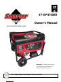 1
1
-
 2
2
-
 3
3
-
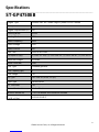 4
4
-
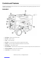 5
5
-
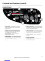 6
6
-
 7
7
-
 8
8
-
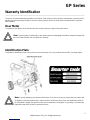 9
9
-
 10
10
-
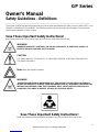 11
11
-
 12
12
-
 13
13
-
 14
14
-
 15
15
-
 16
16
-
 17
17
-
 18
18
-
 19
19
-
 20
20
-
 21
21
-
 22
22
-
 23
23
-
 24
24
-
 25
25
-
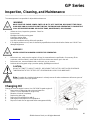 26
26
-
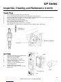 27
27
-
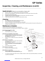 28
28
-
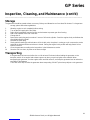 29
29
-
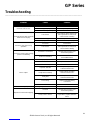 30
30
-
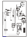 31
31
-
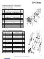 32
32
-
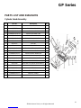 33
33
-
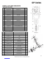 34
34
-
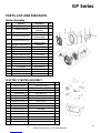 35
35
-
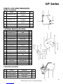 36
36
-
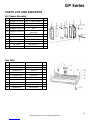 37
37
-
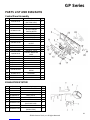 38
38
-
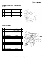 39
39
-
 40
40
-
 41
41
-
 42
42
-
 43
43
-
 44
44
-
 45
45
-
 46
46
-
 47
47
-
 48
48
-
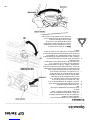 49
49
-
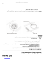 50
50
-
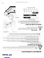 51
51
-
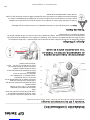 52
52
-
 53
53
-
 54
54
-
 55
55
-
 56
56
-
 57
57
-
 58
58
-
 59
59
-
 60
60
-
 61
61
-
 62
62
-
 63
63
-
 64
64
-
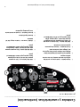 65
65
-
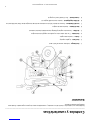 66
66
-
 67
67
-
 68
68
-
 69
69
-
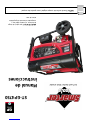 70
70


Smarter Tools ST-GP4750EB El manual del propietario
- Categoría
- Generadores de poder
- Tipo
- El manual del propietario
