
MANUAL DE INSTRUCCIONES
A-257DTM Versión 1.7 1/1
A-257DTM
ATENCI
Ó
N:
La instalación debe ser realizada por personal técnico
cualificado.
Conectar en paralelo los altavoces a los terminales de
salida correspondientes del amplificador.
Asegurarse de que todos los altavoces tengan la
misma polaridad.
No cambiar la toma del transformador mientras el
altavoz está en funcionamiento.
No exponer el equipo a fuentes de calor, ni a la llama.
ALTAVOZ DE TECHO
CARACTERÍSTICAS
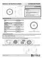
Paso 1 – Recorte el tamaño del agujero. Utilice una plantilla de cartulina o un Cutter circular ajustado al tamaño requerido.
Paso 2 – Pase los cables a través del agujero.
Paso 3 – Conecte los cables. Por favor, asegúrese que la polaridad es la correcta.
Paso 4 – Inserte el altavoz en el techo y fíjelo. Inserte el altavoz hasta que los bordes del frontal toquen el techo. Gire los tornillos de sujeción
en el sentido de las agujas del reloj para apretar las lengüetas de montaje. NO SOBREAPRIETE.
Paso 5 – Conecte el altavoz. Si utiliza una línea de alta impedancia (100 / 70 V), conéctela al terminal de transformador correspondiente según
la potencia deseada. Si utiliza una línea de 8 , desconecte los cables del transformador y conéctela directamente a los terminales del altavoz.
Modelo A-257DTM
Altavoz
Graves 6,5” Kevlar
Agudos 0,75”
Potencia RMS
60 W a 8 , 20 W a 100 V
Selección de potencia 100V 20 W ,10 W y 5 W
Impedancia
666 , 1k3 , 2k7 y 8
Sensibilidad 90 dB SPL a 1 W, 1 m y 1 kHz
Presión acústica 103 dB a 20 W, 1 m y 1 kHz
Respuesta en frecuencia 65 ~ 20000 Hz
Orificio a empotrar Ø 210 mm
Dimensiones (mm) Ø 227 x 87 (fondo)
Peso 1,75 kg
Acabado ABS, rejilla metálica
Color Blanco
Montaje Lengüetas rotatorias
GUÍA DE INSTALACIÓN
Ecualizador del Tweeter +3 dB/-3 dB

INSTRUCTION MANUAL
A-257DTM Version 1.7 1/1
A-257DTM
WARNING:
Installation by qualified personnel only.
Speakers must be wired in parallel and connected to
the correct line terminals of amplifier.
Ensure that all speakers have the same polarity with
respect to each other.
Do not select another tapings if the speaker is in use.
No naked flame sources, such as lighted candles,
should be placed on the apparatus.
CEILING SPEAKER
SPECIFICATIONS
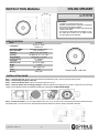
Step 1 – Cutout the hole size, either by tracing the cardboard cutout template or with a circular cutter set to the cutout size.
Step 2 – Pull the wiring through the cutout hole.
Step 3 – Connect the speaker wires. Please, ensure that the polarity is correct.
Step 4 – Insert the speaker into the ceiling and tighten. Insert the speaker into the ceiling as far as it goes, until the front rim touches the
ceiling. Turn the attachment screws CLOCKWISE to tighten the mounting tabs. DO NOT OVERTIGHTEN.
Step 5 - Connect the speaker. If you use a high impedance line (100 / 70 V), connect it to the corresponding transformer terminal according to
the desired power. If you use an 8 line, disconnect the transformer cables and connect it directly to the speaker terminals.
Model A-257DTM
Loudspeaker
Woofer 6.5” Kevlar
Tweeter 0.75”
Rated Power (RMS)
60 W at 8 , 20 W at 100 V
Power Taps 100V 20 W, 10 W & 5 W
Impedance
666 , 1k3 , 2k7 & 8
Sensitivity 90 dB SPL at 1 W, 1 m & 1 kHz
Sound Pressure 103 at 20 W, 1 m & 1 kHz
Frequency Range 65 ~ 20000 Hz
Cutout Size Ø 210 mm
Dimension (mm) Ø 227 x 87 (depth)
Weight 1.75 kg
Finish ABS, metallic grille
Colour White
Mounting Rotary tabs
INSTALLATION GUIDE
Tweeter Equalizer +3 dB/-3 dB
-
 1
1
-
 2
2


en otros idiomas
- English: Optimus A-257DTM User manual
Artículos relacionados
-
Optimus A-258MHQ Manual de usuario
-
-
-
-
-
-
-
Optimus A-256MHQ Manual de usuario
-
-