
MANUAL DE INSTRUCCIONES
A-265VAM Versión 1.0 1/1
A-265VAM
A
TENCI
Ó
N:
La instalación debe ser realizada por personal técnico
cualificado.
Conectar en paralelo los altavoces a los terminales de
salida correspondientes del amplificador.
Asegurarse de que todos los altavoces tengan la
misma polaridad.
No cambiar la toma del transformador mientras el
altavoz está en funcionamiento.
No exponer el equipo a fuentes de calor, ni a la llama.
ALTAVOZ DE TECHO
1
9
0
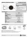
Modelo A-265VAM
Altavoz Graves: 3’5” + Agudos: Tweeter 0’5”
Potencia RMS 15 W
Selección de potencia 100 V 15 W, 7’5 W, 3’75 W, 1’9 W y 8 Ω
Selección de potencia 70 V 7’5 W, 3’75 W, 1’9 W, 1 W y 8 Ω
Impedancia 667 Ω, 1k3 Ω, 2k6 Ω, 5k2 Ω y 8 Ω
Sensibilidad 86 dB SPL a 1 W, 1 m y 1 kHz
Presión acústica 98 dB SPL a 15 W, 1 m y 1 kHz
Respuesta en frecuencia (-10dB) 85 ~ 25.000 Hz
Orificio a empotrar Ø 170 mm
Dispersión (1kHz / 4kHz) 210º / 140º
Temperatura de funcionamiento -20ºC ~ +60ºC
Dimensiones (mm) Ø 190 x 139 (fondo)
Peso 1’96 kg
Acabado ABS
Color Blanco RAL 9016
Montaje Lengüetas rotatorias
Selección de potencia Selector rotativo
Otros Especial VA. Cumple con BS-5839, parte 8
Paso1 - Recorte el agujero según el tamaño requerido (figura 1).
Paso 2 - Conecte los cables al regletero incluido con el altavoz (figura 2).
Paso 3 - Cierre la tapa del regletero del altavoz con los tornillos correspondientes (figura 3 y figura 4).
Paso 4 - Inserte el altavoz en el techo hasta que el borde delantero deflector toque el techo.
GUÍA DE INSTALACIÓN
CARACTERÍSTICAS

INSTRUCTION MANUAL
A-265VAM Version 1.0 1/1
A-265VAM
WARNING:
Installation by qualified personnel only.
Speakers must be wired in parallel and connected to
the correct line terminals of amplifier.
Ensure that all speakers have the same polarity with
respect to each other.
Do not select another tapings if the speaker is in use.
No naked flame sources, such as lighted candles,
should be placed on the apparatus.
CEILING SPEAKER
1
9
0
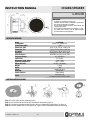
Model A-265VAM
Loudspeaker Woofer 3’5”, tweeter 0’5”
Rated Power (RMS) 15 W
Power taps 100 V 15 W, 7’5 W, 3’75 W, 1’9 W & 8 Ω
Power taps 70 V 7’5 W, 3’75 W, 1’9 W, 1 W & 8 Ω
Impedance 667 Ω, 1k3 Ω, 2k6 Ω, 5k2 Ω y 8 Ω
Sensitivity 86 dB SPL at 1 W, 1 m & 1 kHz
Sound Pressure 98 dB SPL at 15 W, 1 m & 1 kHz
Frequency Range 85 ~ 25.000 Hz
Cutout Size Ø 170 mm
Dispersion (1kHz / 4kHz) 210º / 140º
Operating temperature -20ºC ~ +60ºC
Dimension (mm) Ø 190 x 139 (depth)
Weight 1’96 kg
Finish ABS
Colour White RAL 9016
Mounting Rotary tabs
Power selection Rotary switch
Others
Special for VA.
In compliance with BS-5839, part 8
Step 1 - Cut the hole to the size required (figure 1).
Step 2 - Connect the wires to terminal strip included with the speaker (figure 2).
Step 3 - Fold down the speaker terminal and fix it with the corresponding screws (figure 3 & figure 4).
Step 4 - Insert the speaker into the ceiling as far as it goes, until the front baffle rim touches the ceiling.
INSTALLATION GUIDE
SPECIFICATIONS
-
 1
1
-
 2
2


en otros idiomas
- English: Optimus A-265VAM User manual
Artículos relacionados
-
Optimus CAL-3150VA Manual de usuario
-
Optimus A-265MAC Ficha de datos
-
-
-
-
-
-
-
-