Lucci Air 21309401 Instrucciones de operación
- Categoría
- Ventiladores domésticos
- Tipo
- Instrucciones de operación
Este manual también es adecuado para

For customer support, please contact:
Tel: +1 (949) 800 8488 Email: [email protected] www.beaconlighting.us.
V1.0 (04/2019)
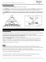
LUCCI
AIRFUSION MARINER
CEILING FAN
• INSTALLATION
• OPERATION
• MAINTENANCE
• WARRANTY INFORMATION
CAUTION
READ INSTRUCTIONS CAREFULLY FOR SAFE
INSTALLATION AND FAN OPERATION.

Mariner Fan Installation Instructions
2 | P a g e SX-50-L-***-01
THANK YOU FOR PURCHASING
Thank you for purchasing this quality Lucci product. To ensure correct function and safety, please read and
follow all instructions carefully before assembly, installation and use of this ceiling fan. Please keep
instructions for future reference.
SAFETY PRECAUTIONS
Read and Save These Instructions
This product conforms to UL standard 507.
1. WARNING -To avoid possible electrical shock, before installing or servicing your fan, disconnect the
power by turning off the circuit breaker of the fuse box to the outlet box.
2. WARNING - To reduce the risk of fire, electric shock, or personal injury, mount to outlet box marked
“acceptable for fan support of 35 lbs (15.9 kg) or less” and use the mounting screws provided with the
outlet box and/or support directly from building structure. Most outlet boxes commonly used for the
support of luminares may not be acceptable for fan support and may need to be replaced. Consult a
qualified electrician if in doubt.
3. WARNING - To reduce the risk of fire or electric shock, do not use this fan with any solid-state speed
control device.
4. WARNING - To reduce the risk of personal injury, do not bend the blade brackets when installing the
blade brackets balancing the blades, or cleaning the fan. Do not insert foreign objects in between rotating
fan blades.
5. CAUTIONS - All wiring must be in accordance with the National Electrical Code (ANSI/NFPA 70) and
local electrical codes. Electrical installation should be performed by a qualified licensed electrician.
6. To reduce the risk of injury to person, the fan must be mounted with a minimum of 7 feet clearance from
the bottom edge of the blades to the floor.
7. After marking electrical connections, spliced conductors should be turned upward and pushed carefully
up into the outlet box. The wires should be spread apart with the grounded conductor and the equipment-
grounding conductor on one side of the outlet box.
8. This equipment has been tested and found to comply with the limits for a Class B digital device, pursuant
to part 15 of the FCC rules. These limits are to provide reasonable protection against harmful interference
in a residential installation. This equipment generates, uses and can radiate radio frequency energy and
if not installed and used in accordance with the instructions may cause harmful interference to radio
communications.

Mariner Fan Installation Instructions
3 | P a g e SX-50-L-***-01
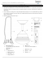
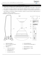
PARTS LIST
• Unpack your ceiling fan and carefully. Remove all parts and hardware.
• Lay out all the components on a smooth surface and make sure there are no components missing before
assembling. If parts are missing, return the complete product to the place of purchase for inspection or
replacement.
• Check whether the ceiling fan has been damaged during transport. Do not operate/install any product
which appears damaged in any way. Return the complete product to the place of purchase for inspection,
repair or replacement.
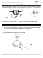
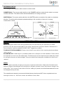
• Identify the parts. Please refer to Fig 1.
1
Mounting bracket x 1
5
Wire nut x 6
2
Pre-assembled fan motor, down rod
and canopy x 1
6
Extra motor screw for blade x 1
3
Blades x 3
7
Balance kit x 1 set
4
• Wood screw x 2
8
Remote x 1 set
• Machine screw x 2
9
Receiver x 1
• Flat washer x 2
• Spring washer x 2
Fig. 1

Mariner Fan Installation Instructions
4 | P a g e SX-50-L-***-01
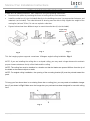
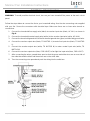
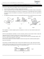
INSTALLING THE MOUNTING BRACKET
If there isn’t an existing outlet box, then install one using the following instructions:
• Disconnect the power by removing the fuses or turning off the circuit breakers.
• Install the outlet box (A) (not included) directly to the building structure. Use appropriate fasteners and
materials (not included). The outlet box and its bracing must be able to fully support the weight of the
moving fan (at least 35 lbs). Do not use a plastic outlet box.
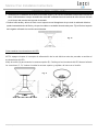
• Figures below show three different ways to mount the outlet box (A) (not included).
This fan hanging system supports a maximum 18 degree angled ceiling installation. Fig. 4
NOTE: If you are installing the ceiling fan on a sloped ceiling, you may need a longer downrod to maintain
proper clearance between the tip of the blade and the ceiling.
NOTE: The ceiling fan must be installed in a location so that the blades are spaced 300mm from the tip of
the blade to the nearest objects or walls.
NOTE: For angled ceiling installation, the opening of the mounting bracket (B) must be pointed toward the
peak.
To hang your fan where there is an existing fixture but no ceiling joist, you may need an installation hanger
bar (C) as shown in Fig.5. Make sure the hanger bar you purchase has been designed for use with ceiling
fans.
Fig. 2
Fig. 5
Fig. 3
Fig. 4
Angled ceiling
Maximum 18°

Mariner Fan Installation Instructions
5 | P a g e SX-50-L-***-01
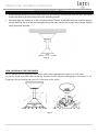
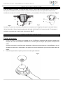
HANGING THE FAN
Pass the power supply wires and ground wire (C) from the ceiling outlet box (B) through the center of the
ceiling mounting bracket (D). Install the ceiling mounting bracket (D) on the outlet box (B) with the mounting
screws (F) provided with the outlet box and washers (E) provided with fan. Fig. 6
Lift the fan assembly onto the mounting bracket. Ensure the key slot (A) of the hanger ball is positioned on
the key pin (B) of the mounting bracket (C) to prevent the fan from rotating when in operation. Fig.7
BLADE INSTALLATION
BLADE ATTACHMENT
1. Align the 3 holes on the blade with the 3 mounting holes on the rotating member of fan motor assembly
and using the 3 blade screws to secure the blade to the fan motor assembly.
Ensure all screws are tightened evenly to reduce the chance of warping or unbalancing. Take care not
to over tighten the screws, as this can damage the blades.
2. Once completed, repeat the process on the remaining blades
Fig. 6
Fig. 7
Fig. 8

Mariner Fan Installation Instructions
6 | P a g e SX-50-L-***-01
ELECTRICAL WIRING DIAGRAM
WARNING: To avoid possible electrical shock, be sure you have turned off the power at the main circuit
panel.
Follow the steps below to connect the fan to your household wiring. Use the wire connecting nuts supplied
with your fan. Secure the connectors with electrical tape. Make sure there are no loose wire strands or
connections.
1. Connect the household live supply wire (black) to receiver input wire (black, AC IN L) as shown in
Fig. 9.
2. Connect the household neutral supply wire (white) to the receiver input wire (white, AC IN N).
3. Connect the household ground wire to the fan bracket ground wire (green) and fan body ground wire.
4. Connect the reveiver output wire (black, TO MOTOR L) to motor live input wire (black, TO MOTOR
L).
5. Connect the receiver output wire (white, TO MOTOR N) to motor neutral input wire (white, TO
MOTOR N)
6. Connect the receiver output wire (blue, FOR LIGHT) to fan light live input wire (blue, FOR LIGHT)
7. After connecting the wires, spread them apart so that the green and white wires are on one side of
the outlet box and the black and blue wires are on the other side.
8. Turn the connecting nuts upward and push the wiring into the outlet box.
Fig. 9

Mariner Fan Installation Instructions
7 | P a g e SX-50-L-***-01
FINISHING THE INSTALLATION
• Ensure the ground wiring is secure and correct, by performing a continuity test from the fan’s accessible
metal body back to the ground terminal at the mounting bracket
• Slide and align the canopy up to the mounting bracket. Ensure all electrical wiring is tucked inside the
canopy and that the wires are not damaged during this step. Secure the canopy to the hanger bracket
using the screws provided.
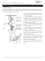
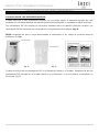
HOW TO REPLACE THE LED DRIVER
NOTE: Always turn Off the power at the mains switch before attempting to replace the LED driver.
Loosen the screw (A) to lift the top housing (B). Replace the LED driver by unplugging the connectors (C, D).
Reposition the top housing and secure it on the down rod by screw.
Fig. 10
Fig. 11

Mariner Fan Installation Instructions
8 | P a g e SX-50-L-***-01
USING YOUR CEILING FAN
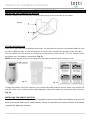
INSTALLING THE TRANSMITTER HOLDER
Install the holder to the wall with two screws provided, hang up the transmitter by the holder.
SETTING DIP SWITCHES
When two or more fans are located near each other, you may desire to have the receiver/transmitter for each
fan set to a different code, so that the operation of one fan does not affect the operation of the other fans.
The DIP switches for the receiver are located on the flat surface of the receiver. The DIP switches for the
transmitter are in the battery compartment. Fig. 12.
NOTE: Ensure that the power to the supply wires has been turned off before setting the code.
Change the position of the DIP switches in the remote transmitter and the receiver. Make sure that the DIP
switches match in the remote receiver and transmitter. If they don’t match, the transmitter will not function.
Fig. 13
INSTALLING THE REMOTE BATTERY
2 x AAA 1.5V (size) batteries are required to operate the remote control. Remove the battery cover from the
back of the remote and insert 2 x AAA batteries. Ensure the polarities are correct as shown in the battery
compartment. (Batteries included.)
Fig. 13
Fig. 12
Fig. 15

Mariner Fan Installation Instructions
9 | P a g e SX-50-L-***-01
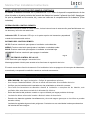
OPERATING THE REMOTE:
Before you start using the remote, take the time to read through this section and get
familiar with the buttons and function of each button.
LED Indicator
The red LED indicator on the top of the transmitter will flash when the buttons are active.
BUTTONS ON THE REMOTE
HI: Press the button to set fan running at High speed.
MED: Press the button to set fan running at Medium speed.
LOW: Press the button to set fan running at Low speed.
OFF: Press the button to turn OFF the fan.
LIGHT CONTROL BUTTON:
Press the button to turn the light ON/OFF.
The remote has memory function. If the fan or light is turned off by the isolating switch, it will memorise and
recover the last status when turned on next.
SAFETY PRECAUTIONS FOR BATTERY
- WARNING – Keep new and used batteries away from children.
- CAUTION – Do not ingest battery—Chemical burn hazard.
- Always use 2 x AAA 1.5V battery type with this ceiling fan remote controller.
- Ensure the batteries are inserted with the correct polarity.
- To prevent false operation during battery insertion or replacement, this ceiling fan must be disconnected
from the supply mains.
- Remove batteries from the product when not in use for long periods of time.
- Batteries must be removed from the remote transmitter before it is discarded.
- Dispose of exhausted batteries immediately and safely (so they cannot be retrieved by children).
Flat batteries can still be dangerous. Contact your local council to safely dispose of the battery.
- Regularly check the product and make sure the battery box lid is correctly secured. If the battery
compartment does not close securely, stop using the product and keep it away from children.
- If you think batteries might have been swallowed or placed inside any part of the body, seek immediate
medical attention for expert advice.
- Battery Leaks: Battery contains chemicals and should be treated as any chemical would. Take
precautions when handling leaked battery chemicals. Battery chemicals should not be placed near the
eyes or ingested.
Fig. 14

Mariner Fan Installation Instructions
10 | P a g e SX-50-L-***-01
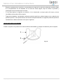
REVERSING SWITCH
Your ceiling fan can operate in either summer or winter mode.
SUMMER Mode: The reverse switch shall be in the SUMMER position to make the fan rotate in a counter
clockwise direction. The airflow will be directed downwards, for cooling in summer.
WINTER Mode: The reverse switch shall be in the WINTER position to make the fan rotate in a clockwise
direction. The airflow will be directed upwards assisting in the circulation of warm air, for energy
conservation in winter.
AFTER INSTALLATION
WOBBLE:
NOTE: ceiling fans tend to move during operation due to the fact that they are mounted on a rubber
grommet. If the fan was mounted rigidly to the ceiling it would cause excessive vibration. Movement of a
few centimetres is quite acceptable and DOES NOT suggest any problem.
TO REDUCE THE FAN WOBBLE: Please check that all screws which fix the mounting bracket and down
rod are secure.
BALANCING KIT: A balancing kit is provided to balance the ceiling fan on initial installation. Please refer to
the instruction on how to use the balancing kit. The balancing kit can be used to assist re-balancing should
the ceiling fan become un-balanced again. Store your balancing kit away after installation for future use if
required.
NOISE:
When it is quiet (especially at night) you may hear occasional small noises. Slight power fluctuations and
frequency signals superimposed in the electricity for off-peak hot water control, may cause a change in fan
motor noise. This is normal. Please allow a 24-hour “settling-in” period, most noises associated with a new
fan disappear during this time.
The manufacturer’s warranty covers actual faults that may develop and NOT minor complaints such as
hearing the motor run – All electric motors are audible to some extent.
Fig. 16

Mariner Fan Installation Instructions
11 | P a g e SX-50-L-***-01
CARE & CLEANING
NOTE: Always turn OFF the power at the mains switch before performing any maintenance or
attempting to clean your fan.
• Every 6 months periodic cleaning of your ceiling fan is the only maintenance required. Use a soft brush
or lint free cloth to avoid scratching the paint finish. Please turn off electricity power when you do so.
• Do not soak or immerse your ceiling fan in water or other liquids. It could damage the motor or the blades
and create the possibility of an electrical shock.
• Ensure that the fan does not come in contact with any organic solvents or cleaners.
• To clean the fan blade, wipe with only a damp clean cloth with NO organic solvents or cleaners.
• The motor has a permanently lubricated ball bearing so there is no need to oil.
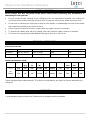
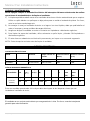
TECHNICAL INFORMATION
ELECTRICAL RATING
SKU#
Model #
Rated Voltage Input
Rated Power (Motor)
Rated Power (Light)
21309401
SX-50-L-WH-01
120V ac, 60Hz
65W
18W
21309501
SX-50-L-BK-01
120V ac, 60Hz
65W
18W
ENERGY EFFICIENCY GUIDE
Fan Size
Speed
Volts
(V)
Amps
(A)
Watts
(W)
RPM
CFM
CFM/W
N.W.
(lbs)
G.W.
(lbs)
C.F.
50”
(ALL
Models)
High
120
0.55
61.75W
220
5330.39
86.3
13.2
13.9
2.37
Low
120
0.23
11.51W
80
1909.38
165.9
N/A
N/A
N/A
These are approximate measurements. They do not include data for any lamps or fixtures attached to the
ceiling fan.
WARRANTY
1 year warranty covers the entire fan. Please refer to warranty card for the details.

Mariner Fan Installation Instructions
12 | P a g e SX-50-L-***-01
GRACIAS POR SU COMPRA
Gracias por adquirir este producto de calidad Lucci. Para garantizar un funcionamiento correcto y seguro,
lea con atención y siga todas las instrucciones antes de armar, instalar y usar este ventilador de techo.
Conserve las instrucciones para futuras consultas.
MEDIDAS DE SEGURIDAD
Lea y guarde estas instrucciones
Este producto cumple con la norma 507 de UL.
1. ADVERTENCIA - Para evitar posibles descargas eléctricas, corte la corriente que va a la caja eléctrica
desde el disyuntor o la caja de fusibles.
2. ADVERTENCIA - Para reducir el riesgo de incendio, descarga eléctrica o lesión, móntelo en una caja
eléctrica clasificada como «Apropiada para sostener ventiladores de 35 lb (15,9 kg) o menos», y utilice
los tornillos de montaje suministrados con la caja eléctrica y/o fíjelo directamente a la estructura del
edificio. La mayoría de las cajas eléctricas utilizadas comúnmente para el soporte de alumbrados puede
que no sean apropiadas para sostener el ventilador y deban ser reemplazadas. Consulte con un
electricista cualificado en caso de duda.
3. ADVERTENCIA - Para reducir el riesgo de incendio o electrocución, evite utilizar el ventilador con un
dispositivo semiconductor para el control de la velocidad.
4. ADVERTENCIA - Para reducir el riesgo de lesión, no doble los soportes de las aspas cuando los instale
en el que equilibran las aspas, o cuando limpie el ventilador. No inserte objetos entre las aspas en
rotación.
5. PRECAUCIÓN - Todo el cableado debe realizarse cumpliendo con el Código Eléctrico Nacional
(ANSI/NFPA 70) y los reglamentos de electricidad locales. La instalación eléctrica debería efectuarla un
electricista acreditado.
6. Para reducir el riesgo de lesiones a personas, el ventilador debe montarse dejando un espacio mínimo
de 2,1m desde el lado inferior de las aspas hasta el suelo.
7. Después de realizar las conexiones eléctricas, los conductores empalmados deben reorientarse hacia
arriba y empujarse con cuidado hacia el interior de la caja eléctrica. Los cables deben quedar apartados,
con el conductor de tierra y el conductor de tierra del dispositivo a un lado de la caja eléctrica.
8. Tras someterlo a una serie de pruebas, se ha constatado que este aparato cumple los límites exigidos
para dispositivos digitales pertenecientes a la Categoría B, según lo establecido en la sección 15 de la
legislación de la FCC. Estos límites están diseñados para proporcionar una protección razonable contra
interferencias en instalaciones residenciales. Este aparato genera, usa y puede irradiar energía en forma
de radiofrecuencia. En caso de no ser instalado y utilizado de acuerdo con las instrucciones, podría
causar interferencias en las comunicaciones de radio.

Mariner Fan Installation Instructions
13 | P a g e SX-50-L-***-01
LISTA DE PIEZAS
• Desembale su ventilador de techo y saque todas las piezas y la tornillería.
• Coloque todos los componentes sobre una superficie lisa y verifique que no falta ninguno. Si falta alguna
pieza, regrese el producto completo al comercio donde lo adquirió para que lo examinen o reemplacen.
• Compruebe si el ventilador de techo se dañó durante el transporte. No opere/instale productos que se
vean dañados en modo alguno. Regrese el producto completo al comercio donde lo adquirió para que lo
examinen, reparen o reemplacen.
Identifique sus componentes. Consulte la Fig. 1.
1
Soporte de montaje x 1
5
Tuerca de alambre x 6
2
Motor del ventilador, tija y florón
preensamblados x 1
6
Tornillo extra de motor para aspa x 1
3
Aspas x 3
7
Kit de equilibrado x 1 juego
4
• Tornillo para madera x 2
8
Mando a distancia x 1 juego
• Tornillo para metal x 2
9
Receptor x 1
• Arandela plana x 2
• Arandela de resorte x 2
Fig. 1

Mariner Fan Installation Instructions
14 | P a g e SX-50-L-***-01
INSTALACIÓN DEL SOPORTE MURAL
Si no hay una caja eléctrica ya instalada, instale una siguiendo estas instrucciones:
• Corte la corriente quitando los fusibles o bajando los disyuntores.
• Instale la caja eléctrica (A) (no incluida) directamente a la estructura del edifico. Utilice los elementos y
materiales de fijación apropiados (no incluidos). La caja eléctrica y su apuntalamiento deben ser capaces
de soportar el peso del ventilador en movimiento (15,9 kg como mínimo). No utilice una caja eléctrica
de plástico.
• Las imágenes más abajo muestran tres maneras diferentes de montar la caja eléctrica (A) (no incluida).
Este ventilador con sistema colgante puede ser instalado en un techo con una inclinación máxima de 18
grados. Fig. 4
NOTA: Si está instalando el ventilador en un techo inclinado, puede que sea necesario utilizar una tija más
larga para mantener el espacio necesario entre el extremo del aspa y el techo.
NOTA: El ventilador de techo debe instalarse en un lugar donde los extremos de las aspas queden a 300
mm como mínimo de las paredes y otros objetos.
NOTA: Para la instalación en techos inclinados, la abertura del soporte del ventilador (B) debe apuntar
hacia el pico del techo.
Para colgar su ventilador donde ya haya un elemento de instalación pero sin vigas, puede que necesite
instalar una barra para colgar (C) como la mostrada en la imagen 5. Asegúrese de que la barra de colgar
que adquiera haya sido diseñada para usarse con ventiladores de techo.
Fig. 2
Fig. 5
Fig. 3
Fig. 4
Techo inclinado
Máximo 18°

Mariner Fan Installation Instructions
15 | P a g e SX-50-L-***-01
CÓMO COLGAR EL VENTILADOR
Pase los cables de corriente y el cable de toma a tierra (C) de la caja eléctrica del techo (B) por el centro
del soporte mural del techo (D). Instale el soporte mural del techo (D) en la caja eléctrica (B) con los
tornillos de montaje (F) incluidos con la caja eléctrica y las arandelas (E) incluidas con el ventilador. Fig. 6
Levante el conjunto del ventilador y móntelo en el soporte mural. Asegúrese de que la ranura de la llave
(A) de la bola de la tija esté posicionada sobre la clavija de la llave (B) del soporte mural (C) para que el
ventilador no pueda girar cuando esté funcionando. Fig. 7
INSTALACIÓN DEL VENTILADOR
Fijación de las aspas
1. Ponga en línea los 3 orificios de las aspas con los 3 orificios de instalación del elemento giratorio del
conjunto del motor del ventilador utilizando los 3 tornillos para las aspas para fijarlas al conjunto del
motor.
Verifique que todos los tornillos están apretados uniformemente para disminuir la posibilidad de que el
ventilador se deforme o desequilibre. No apriete los tornillos demasiado ya que esto puede dañar las
aspas.
2. Cuando haya acabado, repita el proceso con las aspas restantes.
Fig. 6
Fig. 7
Fig. 8

Mariner Fan Installation Instructions
16 | P a g e SX-50-L-***-01
DIAGRAMA DE CONEXIONES ELÉCTRICAS
ADVERTENCIA: Para evitar posibles descargas eléctricas, asegúrese de que la corriente esté cortada en
el cuadro de distribución.
Siga los pasos siguientes para conectar el ventilador al cableado doméstico. Utilice las tuercas de conexión
de alambre suministradas con su ventilador. Asegure los conectores con cinta aislante. Asegúrese de que
no haya hilos de cable o conexiones sueltos.
1. Conecte el cable de fase doméstico (negro) al
cable de entrada del receptor (negro, CA EN L)
como muestra la Fig. 9.
2. Conecte el cable neutro doméstico (blanco) al
cable de entrada del receptor (blanco, CA EN N).
3. Conecte el cable de tierra doméstico al cable
de tierra del soporte del ventilador (verde) y al cable
de tierra del cuerpo del ventilador.
4. Conecte el cable de salida del receptor (negro,
A MOTOR L) al cable de entrada de fase del motor
(negro, A MOTOR L).
5. Conecte el cable de salida del receptor (blanco,
A MOTOR N) al cable de entrada de neutro del
motor (blanco, A MOTOR N).
6. Conecte el cable de salida del receptor (azul,
PARA LUZ) al cable de entrada de fase de la luz del
ventilador (azul, PARA LUZ).
7. Tras conectar los cables, apártelos unos de
otros de manera que los cables verdes y blancos
queden a un lado de la caja eléctrica y los cables
negro y azul queden al otro lado.
8. Oriente las tuercas de alambre hacia arriba y
empuje los cables hacia el interior de la caja
eléctrica.
Fig. 9

Mariner Fan Installation Instructions
17 | P a g e SX-50-L-***-01
CÓMO FINALIZAR LA INSTALACIÓN
• Verifique que el cableado de la toma a tierra está seguro y es correcto realizando una prueba continua de
toma a tierra desde el cuerpo accesible de metal del ventilador hacia el teminal de toma a tierra ubicado
en el bloque del terminal del soporte de armado.
Deslice hacia arriba y alinee el florón con el soporte mural. Asegúrese de que todo el cableado eléctrico
quede insertado dentro del florón y de que los cables no se dañen durante este paso. Fije el florón al soporte
del colgador utilizando los tornillos suministrados.
Cómo cambiar el accionamiento del LED
NOTA: apague siempre el inerruptor de alimentación de la red eléctrica antes de proceder a cambiar el
accionamiento del LED.
Afloje el tornillo (A) para levantar la carcasa superior (B). Sustituya el accionamiento del LED desenchufando
los conectores (C, D). Vuelva a instalar la carcasa superior y sujétela a la barra con el tornillo.
Fig. 11
Fig. 10

Mariner Fan Installation Instructions
18 | P a g e SX-50-L-***-01
MODO DE EMPLEO DEL VENTILADOR DE TECHO
COLOCACIÓN DE LOS INTERRUPTORES DIP
Cuando haya dos o más ventiladores próximos, tal vez desee ajustar el transmisor/receptor de cada
ventilador con un código diferente, de manera que el funcionamiento de un ventilador no afecte al de otro.
Los interruptores DIP del receptor se encuentran ubicados sobre la superficie plana del receptor. Los
interruptores DIP del transmisor se encuentran en el compartimento de la batería. Fig. 12.
NOTA: Asegúrese de que se haya desconectado la alimentación a los cables de corriente antes de
establecer el código.
Cambie la posición de los interruptores DIP en el transmisor remoto y el receptor. Asegúrese de que los
interruptores DIP coincidan en el receptor remoto y en el transmisor. Si no coincidieran, el transmisor no
funcionará. Fig. 13
Fig. 13
Fig. 12
Interruptores DIP
Interruptores DIP
Fig. 13

Mariner Fan Installation Instructions
19 | P a g e SX-50-L-***-01
INSTALACIÓN DE LAS PILAS DEL MANDO A DISTANCIA
El mando a distancia funciona con 2 pilas AAA de 1,5V. Retire la tapa del compartimiento de las
pilas ubicada en la parte posterior del mando de distancia e inserte 2 pilas de tipo AAA. Asegúrese
de que la polaridad es la correcta, tal y como se indica en el compartimento de la batería. (Pilas
incluidas).
OPERACIÓN DEL CONTROL REMOTO:
Antes de comenzar a utilizar el control remoto, lea las instrucciones de esta sección para familiarizarse con
los botones y la función de cada botón.
Indicador LED: El indicador LED rojo en la parte superior del transmisor parpadeará
cuando los botones están activos.
BOTONES DEL CONTROL REMOTO
ALTO: Presione este botón para ajustar el ventilador a velocidad alta.
MEDIO: Presione este botón para ajustar el ventilador a velocidad media.
BAJO: Presione este botón para ajustar el ventilador a velocidad baja.
APAGADO: Presione este botón para apagar el ventilador.
BOTÓN DE CONTROL DE LA LUZ:
Pulse este botón para apagar o encender la luz.
Mantenga pulsado el botón para acceder a las funciones de regulación de la luz.
El control remoto tiene función de memoria. Si el ventilador o la luz se apaga con el interruptor de aislamiento,
memorizará y recuperará la condición cuando se encienda nuevamente.
MEDIDAS SE SEGURIDAD CON LAS BATERÍAS
- ADVERTENCIA – Mantenga las baterías nuevas y usadas fuera del alcance de los niños.
- PRECAUCIÓN – No ingerir las baterías—Peligro de quemaduras químicas.
- Use siempre 2 baterías AAA de 1,5V con el mando a distancia de este ventilador de techo.
- Verifique que las baterías están insertadas con las polaridades en dirección correcta.
- Para evitar funcionamientos accidentales durante la instalación o reemplazo de las baterías, este
ventilador debe estar desconectado de la alimentación eléctrica.
- Retire las baterías del producto cuando no vaya a utilizarlo por largos periodos de tiempo.
- Las baterías deben retirarse del mando a distancia antes de desecharlo.
- Deseche las baterías agotadas inmediatamente y de modo seguro (para que no los niños no puedan
acceder a ellas).
Las baterías agotadas siguen siendo peligrosas. Contacte con sus autoridades locales para desechar
las baterías de forma segura.
Fig. 14

Mariner Fan Installation Instructions
20 | P a g e SX-50-L-***-01
- Examine regularmente el producto y compruebe que la tapa de la caja de las baterías está bien fijada.
Si el compartimento de las baterías no se cierra de forma segura, deje de utilizar el producto y
manténgalo fuera del alcance de los niños.
- Si cree que alguien ha ingerido una batería o la ha introducido en alguna parte del cuerpo, procure
inmediatamente ayuda médica experta.
- Fugas de las baterías: Las baterías contienen productos químicos y deben tratarse como cualquier otro
producto químico. Tome precauciones a la hora de manipular baterías con fugas de productos químicos.
Las baterías no deben acercarse a los ojos ni ingerirse.
INSTALACIÓN DEL PORTAMANDO
Instale el soporte en la pared con los dos tornillos suministrados y cuelgue el transmisor junto al soporte.
Fig. 15

Mariner Fan Installation Instructions
21 | P a g e SX-50-L-***-01
Funcionamiento reversible
Su ventilador puede girar en dirección de reloj o en la contraria.
Modo VERANO: Si el interruptor para dirección del giro está hacia “abajo” (SUMMER) el ventilador girará
en sentido antihorario. El flujo de aire estará dirigido hacia abajo para enfriar con una brisa directa.
Modo INVIERNO: Si el interruptor para dirección del giro está hacia “arriba” (WINTER) el ventilador girará
contra dirección de reloj. El flujo de aire estará dirigido hacia el techo para distribuir el aire calido cerca del
techo.
DESPUÉS DE LA INSTALACIÓN
BALANCEO DEL EJE:
Nota: los ventiladores de techo tienden a moverse durante su funcionamiento debido al hecho de que están
montados sobre un ojal de goma. Si el ventilador se monta de forma rígida en el techo podría provocar una vibración
excesiva. El movimiento de unos centímetros es bastante aceptable y no sugiere ningún problema.
PARA REDUCIR EL BALANCEO DEL EJE DEL VENTILADOR: por favor, compruebe que todos los tornillos que se
fijan a la abrazadera de montaje y a la varilla vertical están seguros.
KIT DE EQUILIBRADO: se suministra un kit de equilibrado en la instalación inicial. Por favor, remítase a las
instrucciones sobre cómo usar el kit de equilibrado. Se puede usar el kit de equilibrado para ayudar a volver a
equilibrarse en caso de que el ventilador de techo se vuelva a desequilibrar. Guarde el kit de equilibrado tras la
instalación para su uso futuro si es necesario.
RUIDO:
Cuando todo esté silencioso (en especial por la noche) puede oír pequeños ruidos ocasionales. Las ligeras
fluctuaciones de corriente y de señales de frecuencia superpuestas en la electricidad para el control de agua caliente
fuera de las horas punta pueden provocar un cambio en el ruido del motor del ventilador.
Esto es normal. Por favor, deje un periodo de “instalación” de 24 horas; la mayoría de los ruidos asociados con un
ventilador nuevo desaparecen durante este tiempo.
La garantía del fabricante cubre los fallos reales que pueden producirse y NO pequeñas quejas como oír el
funcionamiento del motor – Todos los motores eléctricos se oyen hasta cierto punto.
Fig.16

Mariner Fan Installation Instructions
22 | P a g e SX-50-L-***-01
CUIDADO Y MANTENIMIENTO :
NOTA: Apague siempre la alimentación eléctrica del interruptor del tomacorriente antes de realizar
operaciones de mantenimiento o de limpiar el ventilador.
1) La limpieza periódica cada 6 meses de su ventilador de techo es el único mantenimiento que se requiere.
Utilice un cepillo blando o un paño que no deje pelusa para no arañar el acabado de pintura. Por favor,
corte la corriente cuando haga esto.
2) No sumerja ni remoje el ventilador de techo en el agua ni en otros líquidos, dado que podría dañar el
motor o las aspas y causar posibles descargas eléctricas.
3) Asegúrese de que el ventilador no entre en contacto con limpiadores o disolventes orgánicos.
4) Para limpiar las aspas del ventilador, utilice solamente un paño limpio y húmedo SIN limpiadores o
disolventes orgánicos.
5) El motor tiene un rodamiento con lubricación permanente, por lo que no es necesario engrasarlo.
NOTA: Corte siempre la corriente antes de limpiar el ventilador.
INFORMACIÓN TÉCNICA
CLASIFICACIÓN ELÉCTRICA
SKU#
Modelo #
Voltaje nominal de
entrada
Potencia nominal
(Motor)
Potencia nominal
(Luz)
21309401
SX-50-L-WH-01
120V ca, 60Hz
65W
18W
21309501
SX-50-L-BK-01
120V ca, 60Hz
65W
18W
GUÍA DE EFICIENCIA ENERGÉTICA
Dimensiones
del ventilador
Veloci
dad
Voltios
(V)
Amper
ios (A)
Vatios
(W)
RPM
CFM
CFM/
W
Peso
neto
(lb)
Peso
bruto
(lb)
C.F.
50”
(Todos los
modelos)
High
120
0.55
61.75W
220
5330.39
86.3
13.2
13.9
2.37
Low
120
0.23
11.51W
80
1909.38
165.9
N/A
N/A
N/A
Éstas son medidas aproximadas. No incluyen datos de ninguna de las lámparas o luces que van
instaladas al ventilador de techo.
GARANTÍA
El ventilador en su conjunto está cubierto por una garantía de 1 años. Por favor, consulte la tarjeta de
garantía para más información.
-
 1
1
-
 2
2
-
 3
3
-
 4
4
-
 5
5
-
 6
6
-
 7
7
-
 8
8
-
 9
9
-
 10
10
-
 11
11
-
 12
12
-
 13
13
-
 14
14
-
 15
15
-
 16
16
-
 17
17
-
 18
18
-
 19
19
-
 20
20
-
 21
21
-
 22
22


Lucci Air 21309401 Instrucciones de operación
- Categoría
- Ventiladores domésticos
- Tipo
- Instrucciones de operación
- Este manual también es adecuado para
En otros idiomas
Documentos relacionados
-
Lucci Air 21299801 Instrucciones de operación
-
-
-
-
-
-
LUCCI Airfusion Radar DC Ceiling Fan Manual de usuario
-
-