
Page 1
VENTILATION FAN / LIGHT MODEL QTXE150FLT
WARNING
TO REDUCE THE RISK OF FIRE, ELECTRIC SHOCK, OR
INJURY TO PERSONS, OBSERVE THE FOLLOWING:
1. Use this unit only in the manner intended by the manufacturer.
If you have questions, contact the manufacturer at the address
or telephone number listed in the warranty.
2. Before servicing or cleaning unit, switch power off at service
panel and lock the service disconnecting means to prevent
power from being switched on accidentally. When the service
disconnecting means cannot be locked, securely fasten a promi-
nent warning device, such as a tag, to the service panel.
3. Installation work and electrical wiring must be done by a qualified
person(s) in accordance with all applicable codes and standards,
including fire-rated construction codes and standards.
4. Sufficient air is needed for proper combustion and exhausting
of gases through the flue (chimney) of fuel burning equipment
to prevent backdrafting. Follow the heating equipment manufac-
turer’s guideline and safety standards such as those published
by the National Fire Protection Association (NFPA), and the
American Society for Heating, Refrigeration and Air Conditioning
Engineers (ASHRAE), and the local code authorities.
5. When cutting or drilling into wall or ceiling, do not damage elec-
trical wiring and other hidden utilities.
6. Ducted fans must always be vented to the outdoors.
7. Acceptable for use over a tub or shower when connected to a
GFCI (Ground Fault Circuit Interrupter) - protected branch circuit
(ceiling installation only).
8. This unit must be grounded.
CAUTION
1. For general ventilating use only. Do not use to exhaust hazardous
or explosive materials and vapors.
2. This product is designed for installation in ceilings up to a 12/12
pitch (45 degree angle). Duct connector must point up. DO NOT
MOUNT THIS PRODUCT IN A WALL.
3. To avoid motor bearing damage and noisy and/or unbalanced
impellers, keep drywall spray, construction dust, etc. off power unit.
4. Please read specification label on product for further information
and requirements.
READ AND SAVE
THESE INSTRUCTIONS
WARRANTY
Installer: Leave this manual with
the homeowner.
OPERATION
CLEANING & MAINTENANCE
For quiet and efficient operation, long life, and attractive appear-
ance - lower or remove grille and vacuum interior of unit with the
dusting brush attachment.
The motor is permanently lubricated and never needs oiling. If the
motor bearings are making excessive or unusual noises, replace
the blower assembly (includes motor and impeller).
Register your
product online at:
www.broan.com/register
Use an on/off switch or speed control to operate this ventilator. See
“Connect Wiring” for details.
Use of speed controls other than the
Broan Models 78V and 78W may cause a motor humming noise.
Limited Warranty
Warranty Period and Exclusions: Broan-NuTone LLC (the “Company”) warrants to the original
consumer purchaser of its product (“you”) that the product (the “Product”) will be free from
material defects in the Product or its workmanship for a period of three (3) years from the date of
original purchase.
The limited warranty period for any replacement parts provided by the Company and for any Products
repaired or replaced under this limited warranty shall be the remainder of the original warranty period.
This warranty does not cover speed controls, fluorescent lamp starters, tubes, halogen and in-
candescent bulbs, fuses, filters, ducts, roof caps, wall caps and other accessories for ducting that
may be purchased separately and installed with the Product. This warranty also does not cover
(a)normal maintenance and service, (b)normal wear and tear, (c)any Products or parts which
have been subject to misuse, abuse, abnormal usage, negligence, accident, improper or insufficient
maintenance, storage or repair (other than repair by the Company), (d)damage caused by faulty
installation, or installation or use contrary to recommendations or instructions, (e)any Product
that has been moved from its original point of installation, (f)damage caused by environmental or
natural elements, (g)damage in transit, (h)natural wear of finish, (i)Products in commercial or
nonresidential use, or (j)damage caused by fire, flood or other act of God. This warranty covers
only Products sold to original consumers in the United States by the Company or U.S. distributors
authorized by the Company.
This warranty supersedes all prior warranties and is not transferable from the original consumer
purchaser.
No Other Warranties: This Limited Warranty contains the Company’s sole obligation and your sole
remedy for defective products. The foregoing warranties are exclusive and in lieu of any other war-
ranties, express or implied. THE COMPANY DISCLAIMS AND EXCLUDES ALL OTHER EXPRESS
WARRANTIES, AND DISCLAIMS AND EXCLUDES ALL WARRANTIES IMPLIED BY LAW, INCLUDING
WITHOUT LIMITATION THOSE OF MERCHANTABILITY AND FITNESS FOR A PARTICULAR PUR-
POSE. To the extent that applicable law prohibits the exclusion of implied warranties, the duration
of any applicable implied warranty is limited to the period specified for the express warranty above.
Some states do not allow limitations on how long an implied warranty lasts, so the above limita-
tion may not apply to you. Any oral or written description of the Product is for the sole purpose of
identifying it and shall not be construed as an express warranty.
Whenever possible, each provision of this Limited Warranty shall be interpreted in such manner as
to be effective and valid under applicable law, but if any provision is held to be prohibited or invalid,
such provision shall be ineffective only to the extent of such prohibition or invalidity, without invali-
dating the remainder of such provision or the other remaining provisions of the Limited Warranty.
Remedy: During the applicable limited warranty period, the Company will, at its option, provide
replacement parts for, or repair or replace, without charge, any Product or part thereof, to the extent
the Company finds it to be covered by and in breach of this limited warranty under normal use and
service. The Company will ship the repaired or replaced Product or replacement parts to you at no
charge. You are responsible for all costs for removal, reinstallation and shipping, insurance or other
freight charges incurred in the shipment of the Product or part to the Company. If you must send the
Product or part to the Company, as instructed by the Company, you must properly pack the Product
or part—the Company is not responsible for damage in transit. The Company reserves the right to
utilize reconditioned, refurbished, repaired or remanufactured Products or parts in the warranty repair
or replacement process. Such Products and parts will be comparable in function and performance
to an original Product or part and warranted for the remainder of the original warranty period.
Exclusion of Damages: THE COMPANY’S OBLIGATION TO PROVIDE REPLACEMENT PARTS, OR
REPAIR OR REPLACE, AT THE COMPANY’S OPTION, SHALL BE YOUR SOLE AND EXCLUSIVE
REMEDY UNDER THIS LIMITED WARRANTY AND THE COMPANY’S SOLE AND EXCLUSIVE OBLI-
GATION. THE COMPANY SHALL NOT BE LIABLE FOR INCIDENTAL, INDIRECT, CONSEQUENTIAL
OR SPECIAL DAMAGES ARISING OUT OF OR IN CONNECTION WITH THE PRODUCT, ITS USE
OR PERFORMANCE.
Some states do not allow the exclusion or limitation of incidental or consequential damages, so the
above limitation or exclusion may not apply to you. This warranty gives you specific legal rights,
and you may also have other rights, which vary from state to state.
This warranty covers only replacement or repair of defective Products or parts thereof at the
Company’s main facility and does not include the cost of field service travel and living expenses.
Any assistance the Company provides to or procures for you outside the terms, limitations or exclu-
sions of this limited warranty will not constitute a waiver of such terms, limitations or exclusions,
nor will such assistance extend or revive the warranty.
The Company will not reimburse you for any expenses incurred by you in repairing or replacing
any defective Product, except for those incurred with the Company’s prior written permission.
How to Obtain Warranty Service: To qualify for warranty service, you must (a)notify the Company
at the address or telephone number stated below within seven (7)days of discovering the covered
defect, (b)give the model number and part identification and (c)describe the nature of any defect
in the Product or part. At the time of requesting warranty service, you must present evidence of
the original purchase date. If you cannot provide a copy of the original written limited warranty,
then the terms of the Company’s most current written limited warranty for your particular product
will control.The most current limited written warranties for the Company’s products can be found
at www.broan.com .
Broan-NuTone LLC 926 West State Street, Hartford, WI 53027
www.broan.com 800-637-1453
La página se está cargando...
La página se está cargando...
La página se está cargando...
La página se está cargando...

Página 6
VENTILADOR / LUZ MODELO QTXE150FLT
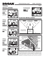
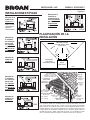
INSTALACIONES TÍPICAS
Montaje de la
cubierta en
viguetas “I”.
Utilice un taco
separador de
viguetas “I”
(suministrado).
Montaje de la
cubierta en
cualquier parte
entre armaduras
por medio
de barras de
suspensión.
Montaje de
la cubierta
en cualquier
parte entre
las viguetas
“I” por medio
de barras de
suspensión.
Montaje de
cubierta en
viguetas.
Montaje de
la cubierta
en cualquier
parte entre
las viguetas
por medio
de barras de
suspensión.
Montaje de
cubierta en
armadura.
PLANIFICACIÓN DE LA
INSTALACIÓN
Equipo
para cocinar
Piso
ÁREA QUE COCINA
No instale sobre o dentro
de esta área.
45
o
45
o
NO PARA EL
USO EN UN
ÁREA QUE COCINA.
TAPA DE
TECHO*
(con
amortiguador
integral)
TAPA DE
PARED*
(con amortiguador
integral)
CODO REDONDO
DE 6 PULG.*
CONDUCTO REDONDO
DE 6 PULG. *
CUBIERTA DE
VENTILADOR
Selle los
huecos alrededor
de la cubierta.
Sellar las juntas
con cinta.
Mantenga
corre
conducto
corto.
AISLAMIENTO
(Puede ser colocado
alrededor y sobre de la
cubierta del ventilador.)
*Se compran
por separado.
O
CABLE DE
ALIMENTACIÓN*
Los conductos desde este ventilador hacia el exterior del edificio tienen un
gran efecto sobre el flujo de aire, el ruido y el uso de energía del ventilador.
Utilice el tramo de conductos más corto y recto posible para obtener un des-
empeño óptimo y evite instalar el ventilador con conductos menores que los
recomendados. El aislamiento alrededor de los conductos puede reducir la
pérdida de energía e inhibir el desarrollo de moho. Los ventiladores instala-
dos en conductos existentes podrían no obtener el flujo de aire nominal.

Página 7
VENTILADOR / LUZ MODELO QTXE150FLT
O BIEN
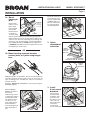
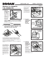
1b. Instale la cubierta en cualquier parte entre
las armaduras, viguetas o viguetas “I” por
medio de barras de suspensión.
Se proporcionan barras de suspensión deslizantes para facilitar
la colocación adecuada de la cubierta en cualquier parte entre la
estructura. Estas barras se adaptan a toda clase de estructuras
(construcciones de viguetas “I”, viguetas estándar y armaduras) y se
extienden a un máximo de 61 cm (24 pulg.).
Fije los CANALES DE MONTAJE a la cubierta con los TORNILLOS
incluidos.
Para lograr un montaje
silencioso: acople
y fije las barras de
suspensión con
TORNILLOS, y doble
los canales de montaje
con un alicate bien
justos alrededor de las
barras de suspensión.
Abra las BARRAS DE
SUSPENSIÓN hasta el
ancho de la estructura.
Sostenga la cubierta
en su lugar para que el
borde inferior de esta
se encuentre al ras con
la superficie acabada
del techo. Para techos
de material de 1/2” de
grueso, posicione la
parte inferior de cada
soporte al ras con la
parte inferior de cada
viga.
INSTALE LA CUBIERTA
Y EL CONDUCTO
2. Acople el
conector del
regulador
de tiro/
conducto.
3. Instale el
conducto
redondo de
6 pulgadas.
Conecte el
conducto redondo
de 6 pulgadas
al conector
del regulador/
conducto. Extienda
el conducto hacia
una tapa de techo
o tapa de pared.
Encinte todas las conexiones de los conductos para fijarlas y
hacerlas herméticas al aire.
1a. Monte la
cubierta en
la vigueta.
Para el montaje
de la cubierta se
utilizan cuatro (4)
tornillos o clavos.
Atornille o clave
la cubierta a la
vigueta a través
de los orificios
más bajos de
cada brida de
montaje, y seguidamente a través de los más altos. NOTA: El
montaje a la VIGUETA “I” (mostrada) requiere utilizar SEPA-
RADORES (incluidos) entre el orificio más alto de cada brida
de montaje y la vigueta “I”.
ESPACIADOR
(utilice para el
montaje de la
I-JOIST)
I-JOIST
BRIDAS SUPERIOR E INFERIOR
QUEDAN FUERA DE LA CUBIERTA
INSERTE
LENGÜETA
EN RANURA
EN CUBIERTA
TORNILLO
DE LA
BOLSA
DE PIEZAS

Página 8
VENTILADOR / LUZ MODELO QTXE150FLT
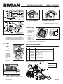
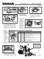
PIEZAS DE REPUESTO
99045436A
Las piezas de recambio
se pueden ahora pedir
en nuestro Web site.
Visítenos por favor en
www.broan.com
Al hacer el pedido de una pieza de servicio se debe especificar el
número de la pieza (no el número de la clave).
Clave n.
o
Pieza n.
o
Descripción
1 97020009 Cubierta
2 97018331 Conector del conducto (6 pulg.)
3 97018721 Bolsa de piezas (incluye placa de cableado y todos los tornillos)
4 97018448 Conjunto del panel de cableado/arnés
5 97020012 Conjunto del ventilador
6 99140208 Resorte de la rejilla (se requieren 2)
7 97018531 Conjunto de la rejilla (incluye la pieza con clave n.
o
6 y 8)
8 99111399 Lente
9 99271381 Bombilla fluorescente, GU24, 18W (se requieren 2)
10 97018014 Separador (se suministran 2)
11 97020013 Juego de barra de suspensión
7
1
2
3
3
3
3
5
4
10
10
11
11
3
6
9
8
6. Acople la rejilla a la cubierta.
Conecte la luz en el receptáculo. Apriete los
resortes de la rejilla e insértelos en las ranuras
que se encuentran a cada lado de la cubierta.
7. Empuje la rejilla
contra el cielo raso.
4. Conecte los cables eléctricos.
Extienda el cableado de la casa de 120 V CA
al lugar de la instalación. Utilice una conexión
aprobada por UL para afianzar el cableado de
la casa a la placa de cableado. Conecte los
cables tal como se ilustra en los diagramas de
cableado.
5. Inserte
máscara
y terminar
el techo.
Máscara de
cinta en la
cubierta. Más-
cara protege la
unidad durante
la construc-
ción. Quite an-
tes de instalar
la rejilla.
Instale el
material del
techo. Recorte
alrededor de la cubierta.
PLACA DE
CABLEADO Y
TORNILLO DE LA
BOLSA DE PIEZAS
8. Saque la lente de la lámpara.
Con cuidado, inserte un destornillador
plano pequeño entre la parilla y la lente de
lámpara. Haga palanca con el destornilla-
dor y saque la lente.
9. Instale las
lámparas.
Producto incluye
(2) lámparas
fluorescentes tipo
GU24 de18W
(máx.), con una
longitud máxima
general (MOL)
de 100 mm (3,9
pulg.). Compre
una lámpara
incandescente nocturna de 4W. Coloque las lámparas en sus adaptadores.
Vuelva a colocar la lente.
3.9" (100mm) M.O.L.
TORNILLO
Transcripción de documentos
VENTILATION FAN / LIGHT MODEL QTXE150FLT Page 1 READ AND SAVE THESE INSTRUCTIONS WARNING TO REDUCE THE RISK OF FIRE, ELECTRIC SHOCK, OR INJURY TO PERSONS, OBSERVE THE FOLLOWING: 1. Use this unit only in the manner intended by the manufacturer. If you have questions, contact the manufacturer at the address or telephone number listed in the warranty. 2. Before servicing or cleaning unit, switch power off at service panel and lock the service disconnecting means to prevent power from being switched on accidentally. When the service disconnecting means cannot be locked, securely fasten a prominent warning device, such as a tag, to the service panel. 3. Installation work and electrical wiring must be done by a qualified person(s) in accordance with all applicable codes and standards, including fire-rated construction codes and standards. 4. Sufficient air is needed for proper combustion and exhausting of gases through the flue (chimney) of fuel burning equipment to prevent backdrafting. Follow the heating equipment manufacturer’s guideline and safety standards such as those published by the National Fire Protection Association (NFPA), and the American Society for Heating, Refrigeration and Air Conditioning Engineers (ASHRAE), and the local code authorities. 5. When cutting or drilling into wall or ceiling, do not damage electrical wiring and other hidden utilities. 6. Ducted fans must always be vented to the outdoors. 7. Acceptable for use over a tub or shower when connected to a GFCI (Ground Fault Circuit Interrupter) - protected branch circuit (ceiling installation only). 8. This unit must be grounded. CAUTION 1. For general ventilating use only. Do not use to exhaust hazardous or explosive materials and vapors. 2. This product is designed for installation in ceilings up to a 12/12 pitch (45 degree angle). Duct connector must point up. DO NOT MOUNT THIS PRODUCT IN A WALL. 3. To avoid motor bearing damage and noisy and/or unbalanced impellers, keep drywall spray, construction dust, etc. off power unit. 4. Please read specification label on product for further information and requirements. CLEANING & MAINTENANCE For quiet and efficient operation, long life, and attractive appearance - lower or remove grille and vacuum interior of unit with the dusting brush attachment. The motor is permanently lubricated and never needs oiling. If the motor bearings are making excessive or unusual noises, replace the blower assembly (includes motor and impeller). OPERATION Use an on/off switch or speed control to operate this ventilator. See “Connect Wiring” for details. Use of speed controls other than the Broan Models 78V and 78W may cause a motor humming noise. Register your product online at: www.broan.com/register WARRANTY Limited Warranty Warranty Period and Exclusions: Broan-NuTone LLC (the “Company”) warrants to the original consumer purchaser of its product (“you”) that the product (the “Product”) will be free from material defects in the Product or its workmanship for a period of three (3) years from the date of original purchase. The limited warranty period for any replacement parts provided by the Company and for any Products repaired or replaced under this limited warranty shall be the remainder of the original warranty period. This warranty does not cover speed controls, fluorescent lamp starters, tubes, halogen and incandescent bulbs, fuses, filters, ducts, roof caps, wall caps and other accessories for ducting that may be purchased separately and installed with the Product. This warranty also does not cover (a) normal maintenance and service, (b) normal wear and tear, (c) any Products or parts which have been subject to misuse, abuse, abnormal usage, negligence, accident, improper or insufficient maintenance, storage or repair (other than repair by the Company), (d) damage caused by faulty installation, or installation or use contrary to recommendations or instructions, (e) any Product that has been moved from its original point of installation, (f) damage caused by environmental or natural elements, (g) damage in transit, (h) natural wear of finish, (i) Products in commercial or nonresidential use, or (j) damage caused by fire, flood or other act of God. This warranty covers only Products sold to original consumers in the United States by the Company or U.S. distributors authorized by the Company. This warranty supersedes all prior warranties and is not transferable from the original consumer purchaser. No Other Warranties: This Limited Warranty contains the Company’s sole obligation and your sole remedy for defective products. The foregoing warranties are exclusive and in lieu of any other warranties, express or implied. THE COMPANY DISCLAIMS AND EXCLUDES ALL OTHER EXPRESS WARRANTIES, AND DISCLAIMS AND EXCLUDES ALL WARRANTIES IMPLIED BY LAW, INCLUDING WITHOUT LIMITATION THOSE OF MERCHANTABILITY AND FITNESS FOR A PARTICULAR PURPOSE. To the extent that applicable law prohibits the exclusion of implied warranties, the duration of any applicable implied warranty is limited to the period specified for the express warranty above. Some states do not allow limitations on how long an implied warranty lasts, so the above limitation may not apply to you. Any oral or written description of the Product is for the sole purpose of identifying it and shall not be construed as an express warranty. Whenever possible, each provision of this Limited Warranty shall be interpreted in such manner as to be effective and valid under applicable law, but if any provision is held to be prohibited or invalid, such provision shall be ineffective only to the extent of such prohibition or invalidity, without invalidating the remainder of such provision or the other remaining provisions of the Limited Warranty. Remedy: During the applicable limited warranty period, the Company will, at its option, provide replacement parts for, or repair or replace, without charge, any Product or part thereof, to the extent the Company finds it to be covered by and in breach of this limited warranty under normal use and service. The Company will ship the repaired or replaced Product or replacement parts to you at no charge. You are responsible for all costs for removal, reinstallation and shipping, insurance or other freight charges incurred in the shipment of the Product or part to the Company. If you must send the Product or part to the Company, as instructed by the Company, you must properly pack the Product or part—the Company is not responsible for damage in transit. The Company reserves the right to utilize reconditioned, refurbished, repaired or remanufactured Products or parts in the warranty repair or replacement process. Such Products and parts will be comparable in function and performance to an original Product or part and warranted for the remainder of the original warranty period. Exclusion of Damages: THE COMPANY’S OBLIGATION TO PROVIDE REPLACEMENT PARTS, OR REPAIR OR REPLACE, AT THE COMPANY’S OPTION, SHALL BE YOUR SOLE AND EXCLUSIVE REMEDY UNDER THIS LIMITED WARRANTY AND THE COMPANY’S SOLE AND EXCLUSIVE OBLIGATION. THE COMPANY SHALL NOT BE LIABLE FOR INCIDENTAL, INDIRECT, CONSEQUENTIAL OR SPECIAL DAMAGES ARISING OUT OF OR IN CONNECTION WITH THE PRODUCT, ITS USE OR PERFORMANCE. Some states do not allow the exclusion or limitation of incidental or consequential damages, so the above limitation or exclusion may not apply to you. This warranty gives you specific legal rights, and you may also have other rights, which vary from state to state. This warranty covers only replacement or repair of defective Products or parts thereof at the Company’s main facility and does not include the cost of field service travel and living expenses. Any assistance the Company provides to or procures for you outside the terms, limitations or exclusions of this limited warranty will not constitute a waiver of such terms, limitations or exclusions, nor will such assistance extend or revive the warranty. The Company will not reimburse you for any expenses incurred by you in repairing or replacing any defective Product, except for those incurred with the Company’s prior written permission. How to Obtain Warranty Service: To qualify for warranty service, you must (a) notify the Company at the address or telephone number stated below within seven (7) days of discovering the covered defect, (b) give the model number and part identification and (c) describe the nature of any defect in the Product or part. At the time of requesting warranty service, you must present evidence of the original purchase date. If you cannot provide a copy of the original written limited warranty, then the terms of the Company’s most current written limited warranty for your particular product will control. The most current limited written warranties for the Company’s products can be found at www.broan.com . Broan-NuTone LLC 926 West State Street, Hartford, WI 53027 www.broan.com 800-637-1453 Installer: Leave this manual with the homeowner. VENTILADOR / LUZ INSTALACIONES TÍPICAS Montaje de la cubierta en viguetas “I”. Utilice un taco separador de viguetas “I” (suministrado). Montaje de la cubierta en cualquier parte entre las viguetas “I” por medio de barras de suspensión. MODELO QTXE150FLT Página 6 Montaje de la cubierta en cualquier parte entre armaduras por medio de barras de suspensión. PLANIFICACIÓN DE LA INSTALACIÓN ÁREA QUE COCINA No instale sobre o dentro de esta área. 45o Montaje de cubierta en viguetas. NO PARA EL USO EN UN ÁREA QUE COCINA. 45o Equipo para cocinar Piso Montaje de la cubierta en cualquier parte entre las viguetas por medio de barras de suspensión. Montaje de cubierta en armadura. AISLAMIENTO (Puede ser colocado alrededor y sobre de la cubierta del ventilador.) TAPA DE TECHO* (con amortiguador integral) CUBIERTA DE VENTILADOR CABLE DE ALIMENTACIÓN* Selle los huecos alrededor de la cubierta. Mantenga corre conducto corto. O CONDUCTO REDONDO DE 6 PULG. * Sellar las juntas con cinta. *Se compran por separado. CODO REDONDO DE 6 PULG.* TAPA DE PARED* (con amortiguador integral) Los conductos desde este ventilador hacia el exterior del edificio tienen un gran efecto sobre el flujo de aire, el ruido y el uso de energía del ventilador. Utilice el tramo de conductos más corto y recto posible para obtener un desempeño óptimo y evite instalar el ventilador con conductos menores que los recomendados. El aislamiento alrededor de los conductos puede reducir la pérdida de energía e inhibir el desarrollo de moho. Los ventiladores instalados en conductos existentes podrían no obtener el flujo de aire nominal. VENTILADOR / LUZ INSTALE LA CUBIERTA Y EL CONDUCTO 1a. Monte la cubierta en la vigueta. ESPACIADOR (utilice para el montaje de la I-JOIST) Para el montaje de la cubierta se utilizan cuatro (4) tornillos o clavos. Atornille o clave la cubierta a la vigueta a través de los orificios I-JOIST más bajos de cada brida de montaje, y seguidamente a través de los más altos. NOTA: El montaje a la VIGUETA “I” (mostrada) requiere utilizar SEPARADORES (incluidos) entre el orificio más alto de cada brida de montaje y la vigueta “I”. O BIEN MODELO QTXE150FLT Página 7 Para lograr un montaje silencioso: acople y fije las barras de suspensión con TORNILLOS, y doble los canales de montaje con un alicate bien justos alrededor de las barras de suspensión. 2. Acople el conector del regulador de tiro/ conducto. 1b. Instale la cubierta en cualquier parte entre las armaduras, viguetas o viguetas “I” por medio de barras de suspensión. INSERTE LENGÜETA EN RANURA EN CUBIERTA BRIDAS SUPERIOR E INFERIOR QUEDAN FUERA DE LA CUBIERTA TORNILLO DE LA BOLSA DE PIEZAS Se proporcionan barras de suspensión deslizantes para facilitar la colocación adecuada de la cubierta en cualquier parte entre la estructura. Estas barras se adaptan a toda clase de estructuras (construcciones de viguetas “I”, viguetas estándar y armaduras) y se extienden a un máximo de 61 cm (24 pulg.). Fije los CANALES DE MONTAJE a la cubierta con los TORNILLOS incluidos. Abra las BARRAS DE SUSPENSIÓN hasta el ancho de la estructura. Sostenga la cubierta en su lugar para que el borde inferior de esta se encuentre al ras con la superficie acabada del techo. Para techos de material de 1/2” de grueso, posicione la parte inferior de cada soporte al ras con la parte inferior de cada viga. 3. Instale el conducto redondo de 6 pulgadas. Conecte el conducto redondo de 6 pulgadas al conector del regulador/ conducto. Extienda el conducto hacia una tapa de techo o tapa de pared. Encinte todas las conexiones de los conductos para fijarlas y hacerlas herméticas al aire. VENTILADOR / LUZ MODELO QTXE150FLT Página 8 8. Saque la lente de la lámpara. 7. Empuje la rejilla contra el cielo raso. PLACA DE CABLEADO Y TORNILLO DE LA BOLSA DE PIEZAS 9. Instale las lámparas. 4. Conecte los cables eléctricos. Extienda el cableado de la casa de 120 V CA al lugar de la instalación. Utilice una conexión aprobada por UL para afianzar el cableado de la casa a la placa de cableado. Conecte los cables tal como se ilustra en los diagramas de cableado. Máscara de cinta en la cubierta. Máscara protege la unidad durante la construcción. Quite antes de instalar la rejilla. Instale el material del techo. Recorte alrededor de la cubierta. 3.9" (100mm) M.O.L. Producto incluye (2) lámparas fluorescentes tipo GU24 de18W (máx.), con una longitud máxima general (MOL) de 100 mm (3,9 pulg.). Compre una lámpara incandescente nocturna de 4W. Coloque las lámparas en sus adaptadores. Vuelva a colocar la lente. TORNILLO 5. Inserte máscara y terminar el techo. Con cuidado, inserte un destornillador plano pequeño entre la parilla y la lente de lámpara. Haga palanca con el destornillador y saque la lente. PIEZAS DE REPUESTO Clave n.o Pieza n.o 1 2 3 4 5 6 7 8 9 10 11 97020009 97018331 97018721 97018448 97020012 99140208 97018531 99111399 99271381 97018014 97020013 Descripción Cubierta Conector del conducto (6 pulg.) Bolsa de piezas (incluye placa de cableado y todos los tornillos) Conjunto del panel de cableado/arnés Conjunto del ventilador Resorte de la rejilla (se requieren 2) Conjunto de la rejilla (incluye la pieza con clave n.o 6 y 8) Lente Bombilla fluorescente, GU24, 18W (se requieren 2) Separador (se suministran 2) Juego de barra de suspensión Al hacer el pedido de una pieza de servicio se debe especificar el número de la pieza (no el número de la clave). Las piezas de recambio se pueden ahora pedir en nuestro Web site. Visítenos por favor en www.broan.com 3 10 1 2 10 11 5 6. Acople la rejilla a la cubierta. Conecte la luz en el receptáculo. Apriete los resortes de la rejilla e insértelos en las ranuras que se encuentran a cada lado de la cubierta. 3 3 6 11 4 3 7 3 9 8 99045436A-
 1
1
-
 2
2
-
 3
3
-
 4
4
-
 5
5
-
 6
6
-
 7
7
-
 8
8


Broan QTXE150FLT Guía de instalación
- Tipo
- Guía de instalación
- Este manual también es adecuado para
en otros idiomas
- English: Broan QTXE150FLT Installation guide