
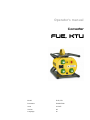
Operator's manual
Converter
FUE, KTU
Model FUE, KTU
Document 5000227699
Issue 01.2017
Version 06
Language en

100_0000_0001.fm
Copyright © 2017 Wacker Neuson Produktion GmbH & Co. KG
Printed in Germany
All rights are reserved, in particular the worldwide applicable copyright, right of duplication and right of
distribution.
This document may only be used by the recipient for the intended purpose. The document may not be
reproduced entirely or partially, or translated into any other language.
Reproduction or translation, even extracts thereof, only with written approval of Wacker Neuson
Produktion GmbH & Co. KG.
Any breach of the statutory provisions, in particular the protection of copyright, will lead to civil and
criminal prosecution.
Wacker Neuson Produktion GmbH & Co. KG is constantly working on the improvement of its products
as part of the technical further development. Therefore, we reserve the right to make changes to the
illustrations and descriptions in this documentation without incurring any obligation to make changes to
machines already delivered.
Errors excepted.
The machine on the cover may have special equipment (options).
Manufacturer
Wacker Neuson Produktion GmbH & Co. KG
Wackerstraße 6
D-85084 Reichertshofen
www.wackerneuson.com
Tel.: +49 845 3340 3200
E-mail address: service-LE@wackerneuson.com
Original operator's manual

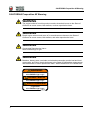
CALIFORNIA Proposition 65 Warning
CALIFORNIA Proposition 65 Warning
2
WARNING
The engine exhaust from this product contains chemicals known to the State of
California to cause cancer, birth defects, or other reproductive harm.
WARNING
Diesel engine exhaust and some of its constituents are known to the State of
California to cause cancer, birth defects, and other reproductive harm.
WARNING
Cancer and Reproductive Harm -
www.P65Warnings.ca.gov.
WARNING
Batteries, battery posts, terminals and related accessories contain lead and lead
compounds, and other chemicals known to the State of California to cause cancer
and birth defects or other reproductive harm. WASH HANDS AFTER HANDLING.
Cancer and Reproductive Harm
www.P65Warnings.ca.gov
Cáncer y daño reproductivo
www.P65Warnings.ca.gov
Cancer ou malformations
congénitales
www.P65Warnings.ca.gov
WARNING
AVERTISSEMENT
ADVERTENCIA
5100045462


Table of contents
5000227699IVZ.fm 3
1 Preface ....................................................................................................................................5
2 Introduction ............................................................................................................................6
2.1 Using the manual......................................................................................................................... 6
2.2 Storage location of the manual.................................................................................................... 6
2.3 Accident prevention regulations................................................................................................... 6
2.4 More information.......................................................................................................................... 6
2.5 Target group................................................................................................................................ 6
2.6 Explanation of symbols................................................................................................................ 6
2.7 Wacker Neuson Contact partner ................................................................................................. 7
2.8 Disclaimer.................................................................................................................................... 7
2.9 Product identification of the machine........................................................................................... 7
3 Safety ......................................................................................................................................8
3.1 Policy........................................................................................................................................... 8
3.2 Competence of the operating personnel.................................................................................... 10
3.3 Protection equipment................................................................................................................. 10
3.4 Transport ................................................................................................................................... 10
3.5 Operational safety...................................................................................................................... 11
3.6 Safety when operating electrical equipment.............................................................................. 11
3.7 Maintenance.............................................................................................................................. 13
4 Safety and information labels ............................................................................................14
5 Setup and function ..............................................................................................................15
5.1 Scope of delivery....................................................................................................................... 15
5.2 Application................................................................................................................................. 15
5.3 Functionality............................................................................................................................... 15
6 Components and operator's controls ................................................................................16
6.1 FUE1, 2 ..................................................................................................................................... 16
6.2 FUE6 ......................................................................................................................................... 16
6.3 KTU2 ......................................................................................................................................... 17
7 Transport ..............................................................................................................................18
8 Operation and use ...............................................................................................................19
8.1 Before commissioning ............................................................................................................... 19
8.2 Commissioning.......................................................................................................................... 19
8.3 Decommissioning ...................................................................................................................... 21
9 Maintenance .........................................................................................................................22
9.1 Maintenance schedule............................................................................................................... 22
9.2 Maintenance jobs....................................................................................................................... 22
10 Troubleshooting ..................................................................................................................24
10.1 FUE1, 2, KTU2 .......................................................................................................................... 24
10.2 FUE6 ......................................................................................................................................... 25
11 Technical data ......................................................................................................................26
11.1 FUE1 ......................................................................................................................................... 26
11.2 FUE2 ......................................................................................................................................... 27
11.3 FUE6 ......................................................................................................................................... 28
11.4 KTU2 ......................................................................................................................................... 29
12 Disposal ................................................................................................................................32
12.1 Disposal of old electrical and electronic equipment................................................................... 32
Inhalt

Table of contents
4 5000227699IVZ.fm
13 Glossary ...............................................................................................................................33
EC declaration of conformity
DIN EN ISO 9001 certificate . . . . . . . . . . . . . . . . . . . . . . . . . . . . . . . . . . . . . . . . . .31

1 Preface
100_0000_0002.fm 5
1 Preface
This operator's manual contains important information and procedures for the safe, proper and economic
operation of this Wacker Neuson machine. Carefully reading, understanding and observing is an aid to
avoiding hazards, repair costs and downtime, and therefore to increasing the availability and service life
of the machine.
This operator's manual is not a manual for extensive maintenance or repair work. Such work should be
carried out by Wacker Neuson service or by technically trained personnel. The Wacker Neuson machine
should be operated and maintained in accordance with this operator's manual. An improper operation or
improper maintenance can pose dangers. Therefore, the operator's manual should be constantly
available at the location of the machine.
Defective machine parts must be exchanged immediately!
If you have any questions concerning the operation or maintenance, a Wacker Neuson contact person
is always available.

2 Introduction
6 100_0000_0013.fm
2Introduction
2.1 Using the manual
This manual is to be considered part of the machine and should be carefully stored during the entire
service life of the machine. This manual shall be transferred to subsequent owners or users of the
machine.
2.2 Storage location of the manual
This manual is part of the machine and must be kept in the immediate vicinity of the machine and made
accessible to staff at all times.
If this manual is lost, or if a second copy is required, there are two options to obtain a replacement:
Download from the Internet: www.wackerneuson.com
Contact your Wacker Neuson contact partner.
2.3 Accident prevention regulations
In addition to the notes and safety instructions in this manual, the local accident prevention regulations
as well as the national health and safety regulations apply.
2.4 More information
This manual applies to various machine types from one product series. For this reason, some figures
may vary slightly in appearance from the machine purchased. Depending on the model, there may be
descriptions of components that are not included in the standard package.
The information contained in this manual is based on machines manufactured up to the time of printing.
Wacker Neuson reserves the right to change this information.
The manufacturer shall immediately include any modifications or additions in this manual.
2.5 Target group
Individuals working with this machine must be regularly trained on the dangers of handling the machine.
This manual is intended for the following people:
Operating personnel:
These individuals have been trained on the machine and informed about the possible dangers in the
event of improper conduct.
Technically trained personnel:
These people have professional training as well as additional knowledge and experience. They are able
to assess the tasks assigned to them and recognize possible dangers.
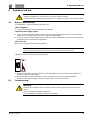
2.6 Explanation of symbols
This manual contains specially emphasized safety instructions in the following categories: DANGER,
WARNING, CAUTION and NOTICE.
Before performing any work on or with this machine, the notes and safety instructions must be read and
understood. All notes and safety instructions in this manual must be passed on to the maintenance,
repair, and transport personnel.
DANGER
This combination of symbol and signal word indicates a hazardous situation that will lead
to death or serious injury if it is not avoided.
WARNING
This combination of symbol and signal word indicates a hazardous situation that can lead
to death or serious injury if it is not avoided.
CAUTION
This combination of symbol and signal word indicates a hazardous situation that can lead
to minor injury or damage to the machine if it is not avoided.

2 Introduction
100_0000_0013.fm 7
2.7 Wacker Neuson Contact partner
Depending on the country, the Wacker Neuson contact partner is a Wacker Neuson service department,
a Wacker Neuson subsidiary, or a Wacker Neuson dealer.
On the Internet at www.wackerneuson.com.
2.8 Disclaimer
For the following violations, Wacker Neuson dismisses any liability for personal injury or material
damage:
Failure to follow this manual.
Unintended use.
Deployment of untrained personnel.
Using non-approved spare parts and accessories.
Improper handling.
Structural modifications of any kind.
Failure to observe the "General Terms and Conditions" (GT&Cs).
2.9 Product identification of the machine
Data of the nameplate
The nameplate contains information that uniquely identifies this machine. This information is required for
ordering spare parts and when inquiring about technical issues.
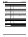
Enter information about the machine in the following table:
NOTICE
Supplementary information.
Designation Your information
Group and model
Year of manufacture
Machine number
Version no.
Item number

3 Safety
8 100_0103_si_0001.fm
3 Safety
3.1 Policy
In keeping with the latest technological developments
The equipment is built in keeping with the latest technological developments and the recognized
technical safety rules. Nevertheless, improper use can result in hazards to life and limb of the user or
third parties or damage to the units and other material assets.
Proper use
The equipment may only be used for the operation of internal and external vibrators.
The equipment to be connected must have the appropriate specifications (voltage, frequency, number
of phases) for the connection.
Use in accordance with the intended purpose also includes the observation of all information in this
operator's manual as well as complying with the prescribed care and maintenance instructions.
Any use that exceeds or is not in accordance with the intended purpose is considered improper. The
manufacturer's liability and warranty are canceled for any damage resulting from improper use. The risk
lies entirely with the operator.
Structural changes
Do not carry out any structural changes without written approval from the manufacturer. You will thereby
be endangering your safety and the safety of others! Additionally, the manufacturer's liability and
warranty will be canceled.
In particular, the following cases are considered structural changes:
Opening the device and permanent removal of components that originate from Wacker Neuson.
Installing new components that do not originate from Wacker Neuson or are not comparable in the
design system and quality of the original parts.
Attaching accessories that do not originate from Wacker Neuson.
Spare parts or accessories that originate from Wacker Neuson can be safely mounted. They can be
found on the Internet under www.wackerneuson.com.
For example, do not drill into the housing to attach signs. Water can enter into the housing and damage
the equipment.
Prerequisite for operation
The flawless and safe operation of the equipment requires the following:
Proper transport, storage and assembly.
Careful operation.
Careful care and maintenance.
Operation
Only operate the equipment in accordance with the intended purpose and in a technically flawless
condition.
Only operate the unit in a safety and hazard-conscious manner and with all protective devices. Do not
change or by-pass any protective devices.
Before beginning work, check the effectiveness of the operator's controls and protective devices.
Never operate the unit in explosive environments.
NOTICE
Read and comply with all notes and safety instructions in this manual. Failure to comply
with these instructions can cause electric shock, fire and/or serious injuries as well as
damage to the machine and/or damage to other objects. Keep safety instructions and
notes for the future.

3 Safety
100_0103_si_0001.fm 9
Maintenance
Regular maintenance jobs are required for a flawless and permanent functioning of the equipment.
Neglected maintenance reduces the equipment's safety.
The prescribed maintenance intervals must be strictly observed.
Do not use the equipment if maintenance or repairs are needed.
Faults
In the event of malfunctions, you must immediately switch the equipment off and secure it.
Immediately rectify faults that can impair safety!
Have damaged or defective components replaced immediately!
You can find more information in the chapter Troubleshooting.
Spare parts, accessories
Only use spare parts from Wacker Neuson or such spare parts that are comparable in the design system
and quality of the original parts.
Only use accessories by Wacker Neuson.
Non-observance cancels out any liability.
Disclaimer
For the following violations, Wacker Neuson dismisses any liability for personal injury or material
damage:
Structural change.
Use not in accordance with the intended purpose.
Non-observance of this operator's manual.
Improper handling.
Using spare parts that do not originate from Wacker Neuson or are not comparable in the design
system and quality of the original parts.
Using accessories that do not originate from Wacker Neuson.
Operator's manual
Always keep the operator's manual readily available on the equipment or at the place of application of
the equipment.
If you should lose the operator's manual or require another copy, please contact your Wacker Neuson
contact partner or download the operator's manual from the Internet (www.wackerneuson.com).
Hand over this operator's manual to every other operator or subsequent owner of the equipment.
Country-specific regulations
Also, observe country-specific regulations, standards and guidelines for accident prevention and
environmental protection, such as dealing with hazardous substances and wearing personal protection
equipment.
Supplement the operator's manual with additional instructions on taking operational, regulatory, national
or generally applicable safety standards into consideration.
Operator's controls
Always keep the equipment operator's controls dry, clean and free from oil and grease.
Operator's controls, such as the ON/OFF switch, throttle control handles, etc. may not be locked,
manipulated or changed without permission.
Check for damage
Check the shutdown equipment at least once per shift for externally visible damage and deficiencies.
Do not operate the equipment if damage or deficiencies are discernible.
Have damage and deficiencies rectified immediately.

3 Safety
10 100_0103_si_0001.fm
3.2 Competence of the operating personnel
Competence of the operator
Only technically trained personnel may start and operate the equipment. In addition, the following
conditions apply:
They are physically and mentally suitable.
They are trained in the independent operation of the equipment.
They are trained how to use the equipment in accordance with the intended purpose.
They are familiar with the necessary safety devices.
They are authorized to operate equipment and systems independently according to the standards of
safety engineering.
They are appointed by the contractor or operator to work independently with the unit.
Faulty operation
In the event of faulty operation, misuse or operation by untrained personnel, you can run the risk of
endangering the health of the operator or third parties as well as damaging the unit or other material
assets.
Operator responsibilities
The user must make the operator's manual available to the operator and ensure that the operator has
read and understood it.
Recommendations for work
Please observe the following recommendations:
Only work if you are in a good physical condition.
Work attentively, especially at the end of working hours.
Do not work with the equipment when you are tired.
Perform all work calmly, cautiously and carefully.
Never work under the influence of alcohol, drugs or medication. Your vision, reactivity and judgment
may be impaired.
Work so that no third parties are harmed.
Make sure that there are no people or animals in the danger area.
3.3 Protection equipment
Workwear
The clothing should be appropriate, i.e. tight fitting, but not cumbersome.
Generally, do not have any long hanging hair, loose clothing or jewelry (including rings) during on site
jobs. There is a risk of injury, for example from being snagged or pulled in on moving equipment parts.
Only wear flame-resistant work clothing.
Personal Protective Equipment
Use personal protection equipment in order to avoid injuries and health hazards:
Safety shoes.
Work gloves made from sturdy material.
Overalls made from sturdy material.
Protective helmet.
Ear protection.
3.4 Transport
Switch off the unit
Before transport, switch the equipment off and remove the plug from the plug receptacle.
Transporting the equipment
Secure the equipment on the means of transport from tipping over, falling down or sliding.

3 Safety
100_0103_si_0001.fm 11
3.5 Operational safety
Explosive area
Never operate the unit in explosive environments.
Work environment
Familiarize yourself with the work environment before beginning work. For example, this includes the
following points:
Obstacles in the work and traffic area.
Load-bearing capacity of the soil.
Necessary protection of the job site, especially for the public transport area.
Necessary protection of walls and ceilings.
Options available in the event of accidents.
Commissioning the unit
Observe the safety information and warnings on the unit as well as those in the operator's manual.
Never operate equipment that is in need of maintenance or repairs.
Commission the unit in accordance with the operator's manual.
Avoid body contact with grounded parts.
Do not use components of the equipment as a climbing aid or securing means
Never use the protection hose, power cable or other components of the equipment as a climbing aid or
securing means.
Switch off the unit
Switch the equipment off and remove the plug from the plug receptacle in the following situations:
Before it breaks.
When you are not using the equipment.
Set the equipment down so that it cannot tip over, fall down or slip.
Storage location
After operation, store the cooled equipment in a locked, clean, frost-protected and dry location that is
inaccessible to children.
3.6 Safety when operating electrical equipment
Electric power supply for electrical equipment of class rating I
You need to connect the equipment to a plug receptacle with a protective earth contact 15 A/16 A with
the corresponding overload fuse protection.
One of the following protective ground fault interrupters is necessary:
Standard protective ground fault interrupter (pulse current sensitive, type A).
All current sensitive protective ground fault interrupter (type B).
NOTICE
The rated voltage can be found on the nameplate of your equipment.

3 Safety
12 100_0103_si_0001.fm
You may only connect the equipment to electric power supplies if all device parts can be found in a
technically perfect condition. In particular, pay attention to the following components:
Plug.
Power cable in its entire length.
Switch membrane of the on/off switch, if present.
Plug receptacles.
You may only connect the unit to electric power supplies with an intact grounded conductor connection
(PE).
When connecting to fixed or mobile power units, at least one of the following safety devices must be
present:
Protective ground fault interrupter (GFI or GFCI).
Insulation monitor.
IT net.
If you connect your equipment to a site power distribution board, this must be grounded.
Extension cable
You may only operate the equipment with undamaged and tested extension cables!
You may only use extension cables with grounded conductors and a proper grounded conductor
connection to the plug and coupling (only equipment of class rating I, see chapter Technical data).
You may only use tested extension cables that are suitable for job site use: average rubber sheathed
cable H05RN-F or better — Wacker Neuson recommend H07RN-F a SOOW cable or a country-specific
equivalent design.
You must immediately replace extension cables with damage (e.g. tears in the casing) or loose plugs
and couplings.
Cable drums and multi-pole plug receptacles must meet the same requirements as extension cables.
Protect extension cable, multi-pole plug receptacles, cable drums and connection couplings from rain,
snow or other forms of moisture.
Uncoil the cable drum completely
Danger of fire due to wound cable drum.
Uncoil the cable drum completely before operation.
Protect the power cable
Do not use the power cable to pull or lift the equipment.
Do not pull the plug of the power cable out of the plug receptacle by pulling the cable.
Protect the power cable from heat, oil and sharp edges.
Have your Wacker Neuson contact partner immediately replace damaged power cables or loose plugs.
Protect against moisture
Protect the equipment from rain, snow or other forms of moisture. Damage and other malfunctions are
possible.
NOTICE
Observe the respective national safety standards!

3 Safety
100_0103_si_0001.fm 13
3.7 Maintenance
Maintenance jobs
Care and maintenance jobs may only be carried out insofar as it is described in this operator's manual.
All other work must be taken over by the Wacker Neuson contact partner.
You can find more information in the chapter Maintenance.
Disconnect from the electric power supply
Before performing maintenance jobs, you must remove the plug from the plug receptacle in order to
disconnect the equipment from the electric power supply.
Cleaning
Always keep the equipment clean and clean it after every use.
Do not use any fuels or solvents. Explosion hazard!
Do not use any high pressure washers. Water ingression can damage the unit. With electrical
equipment, there is a serious risk of injury from electric shock.

4 Safety and information labels
14 100_0103_ls_0001.fm
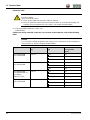
4 Safety and information labels
There are labels on your unit that contain important information and safety instructions.
Keep all labels legible.
Replace missing or illegible labels.
The item numbers on the labels can be found in the parts book.
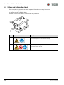
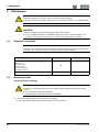
Item Label Description
1
Warning against hot surface.
Read the operator's manual before startup.
2 Attention: electric shock.
Do not open housing.
Read operator's manual.
0219173
0219413

5 Setup and function
100_0103_sf_0001.fm 15
5 Setup and function
5.1 Scope of delivery
The scope of delivery includes:
Machine.
Operator's manual.
5.2 Application
The machine may only be used for the operation of internal and external vibrators.
The machine is used to convert the current on the construction site into current that can be used by the
machines to be connected.
5.3 Functionality
Principle
The machine converts the current on the construction site (e.g. 230 V 1~) in order to operate machines
with special specifications. Voltage, frequency and phase number are adjusted during this process.
Machine features
Short-circuit and earth-fault proof.
Shutdown in the case of excess temperature and fault voltage.
Overload current detection.
Protective low voltage provided by safety isolation transformer (applicable to 42 V machines).
Converter
The c
onverter comprises a current rectifier and a d.c.-a.c. converter monitored by an electronic control.
The current rectifier converts the input voltage (AC single phase) to DC voltage.
The d.c.-a.c. converter converts the generated DC voltage to three phase current (AC three phase).
When the machine is switched on, the control electronics provides a soft start and thus prevents critical
starting currents.

6 Components and operator's controls
16 100_0103_cp_0001.fm
6 Components and operator's controls
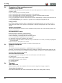
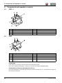
6.1 FUE1, 2
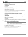
6.2 FUE6
Control lamp
If the machine is correctly connected, the control lamp lights green.
In the case of different indications, a fault has occurred, see Chapter Troubleshooting.
Thumbwheel for frequency adjustment for FUE6...SC
Use the thumbwheel to adjust the output frequency of the machine and, as a result, affect the speed of
the connected machines.
Item Designation Item Designation
1 Protective frame 4 ON/OFF switch
2 Lifting strap 5 Plug receptacle with protective cover
3 Ventilation slots Power cable (not shown)
Item Designation Item Designation
1 Protective frame 5 Control lamp
2 Lifting strap 6 ON/OFF switch
3 Ventilation slots 7 Plug receptacle with protective cover
4 Thumbwheel for frequency adjustment (only
FUE 6...SC)
Power cable (not shown)

6 Components and operator's controls
100_0103_cp_0001.fm 17
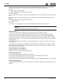
6.3 KTU2
Item Designation Item Designation
1 Protective frame 5 ON/OFF switch
2 Lifting strap 6 Plug receptacle with protective cover
3 Ventilation slots 7 Power cable (not shown)
4 Crank knop

7 Transport
18 100_0103_tr_0001.fm
7 Transport
Transporting the machine
1. Switch off the mac
hine via the ON/OFF switch.
2. Pull the plug from the plug receptacle.
3. Disconnect all connected machines from the
converter.
4. Wind up the power cable.
5. Set the machine on or into a suitable transport vehicle.
6. Fasten the machine to the protective frame.
WARNING
Improper handling may result in injury or serious material damage.
Read and observe all safety instructions in this operator's manual, see chapter Safety.
NOTICE
Do not place the machine on the side where the plug receptacle is lo-cated.

8 Operation and use
100_0103_op_0001.fm 19
8 Operation and use
8.1 Before commissioning
The equipment is ready for operation out of the box.
Check equipment
Check the equipment and all components for damage.
Check the power supply system
Check whether the power supply system or job site electrical distributor has the correct operating
voltage (see nameplate of the unit or the chapter Technical data).
Check whether the power supply system or job site electrical distributor is secured according to the
applicable national standards and guidelines.
Only FUE 6...SC
When connecting internal and external vibrators.
Applicable to inverters with frequency adjustment:
During the operation of internal vibrators, set the thumbwheel to the maximum output frequency
(highest number must be visible).
During operation of external vibrators, use the thumbwheel to search the required output
frequency.The output frequency affects the speed of the connected machines.
8.2 Commissioning
WARNING
Improper handling may result in injury or serious material damage.
Read and observe all safety instructions in this operator's manual, see chapter Safety.
NOTICE
Please also refer to the operator's manual of the internal vibrators/external vibrators.
WARNING
Damage to an equipment part or power cable can lead to physical injury from electric
shock.
Do not operate damaged equipment!
Have damaged equipment repaired immediately.

8 Operation and use
20 100_0103_op_0001.fm
Important notes about connecting consumers
Do not exceed the rated current of all connected consumers
The total rated currents of all connected consumers must not exceed the maximum rated output
current of the converter.
The maximum rated output current is specified on the nameplate.
Example:
FUE 6/042/200W, maximum rated output current 52 A.
You can connect three IREN 57 with a rated current of 17.3 A each s
ince the overall current I = 3 x 17.3 A
= 51.9 A and is therefore less than 52 A.
However, you cannot connect three IREN 65 with a rated current of 25 A each since the overall current
I = 3 x 25 A = 75 A and therefore exceeds 52 A.
Do not exceed the rated current of the plug receptacle
The rated current of every attached consumer must not exceed the maximum rated current of the plug
receptacle.
The maximum rated current is specified on the plug receptacle.
Example:
FUE 6/042/200W, maximum rated current of a plug receptacle 32 A.
You must not connect consumers whose rated current is higher than 32 A.
WARNING
Improper handling c
an damage the insulation of the
converter. Risk of death from electric shock and risk of fire.
The rated current of all connec
ted consumers may not in sum be greater than the
maximum output rated current of the converter.
The rated current of each connected consumer may not be greater than the maximum
rated current of the plug receptacle.

8 Operation and use
100_0103_op_0001.fm 21
Connect the equipment to the electric power supply
Only connect the unit to single-phase AC. For connection values, see the chapter Technical data.
Observe the notes in the chapter Safety when operating electrical units.
1. Switch off the converter via the ON/OFF switch.
2. Switch off all connected machines via the respective equipment switch.
3. If required, connect the machine to a permitted extension cable.
4. Insert the plug into the plug receptacle.
Switching on the machine
Switch on the c
onverter via the ON/OFF switch.
When the machine is ready to operate, the control lamp lights green (FUE 6
only).
8.3 Decommissioning
Switching off the machine
1. Switch off all connected machines via the respective equipment switch.
2. Switch off the converter via the ON/OFF s
witch.
3. Pull the plug from the plug receptacle.
4. Disconnect all connec
ted machines from the converter.
5. Wind up the power cable.
NOTICE
Electrical voltage.
An incorrect voltage can damage the equipment.
Check whether the voltage of the power source conforms to the specifications of the
unit. See chapter Technical data.
WARNING
Start-up of the connected equipment.
Risk of injury from uncontrolled start-up of equipment.
Switch all connected equipment off before connecting to the electric power supply.
WARNING
Electrical voltage.
Injury from electric shock.
Check power cable and extension cable for damage.
Only use extension cables whose grounded conductor is connected to the plug and
coupling (only for equipment of class rating I, see chapter Technical data).
NOTICE
Permissible lengths and cross-sections of extension cables can be found in the chapter
Technical data.

9 Maintenance
22 100_0103_mt_0001.fm
9 Maintenance
9.1 Maintenance schedule
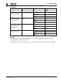
9.2 Maintenance jobs
Visual inspection for damage
Check all equipment parts and components for damage.
Have the damage fixed by your Wacker Neuson contact partner.
WARNING
Improper handling may result in injury or serious material damage.
Read and observe all safety instructions in this operator's manual, see chapter Safety.
WARNING
WARNING
Improper handling may cause a danger to life by electrocution.
Only a qualified electrician is permitted to open the machine, perform repairs, and
perform a subsequent safety check in accordance with applicable regulations.
NOTICE
The time intervals mentioned here are reference values for normal operation. For extreme
operation, e.g. continuous use, the service intervals should be halved.
Activity Daily before operation After operation
Visual inspection of all parts for damage:
Housing.
Power cable.
Lifting strap.
Plug receptacle.
ON/OFF switch.
Clean equipment.
WARNING
Damage to an equipment part or power cable can lead to physical injury from electric
shock.
Do not operate damaged equipment.
Have damaged equipment repaired immediately.

9 Maintenance
100_0103_mt_0001.fm 23
Clean equipment
1. Clean the ventilation slots with a suitable tool.
2. Wipe the housing with a damp and clean cloth.
3. Clean the thumbwheel (applicable to inverters with frequency adjustment).
NOTICE
Do not clean the equipment with high pressure or steam cleaners!

10 Troubleshooting
24 100_0103_ts_0001.fm
10 Troubleshooting
Potential faults, their causes and remedies can be found in the following table.
Notify your Wacker Neuson contact in case of malfunctions you cannot or may not remedy yourself.
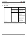
10.1 FUE1, 2, KTU2
Fault Possible causes Remedial measure
Converter not in operation.
Mains voltage interrupted.
Incorrect mains voltage.
The converter starts automatically
as soon as the cor
rect mains
voltage is present (again).
Short circuit in one of the
connected pieces of equipment.
2-phase operation * in one of the
connected pieces of equipment.
Mechanical defect in one of the
connected pieces of equipment.
1. Carry out a reset:
Switc
h off the converter
and switch it on again.
2. Disconnect the connected
machines and check them.
3. Repeat reset.
Short-circuit within the converter. 1. Disconnect connected
m
achines.
2. Carry out a reset:
Switch off the converter and
switch it on again.
3. If the fault is not remedied,
have the machine repaired.
Conver
ter shut down due to
excessive temperature (> 85 °C).
1. A
llow the converter to cool
down. Leave the converter
switched on to allow the
ventilator to keep running.
2. Carry out a reset:
Switch off the converter and
switch it on again.
Reduce the current consumption of
the connected machines.
Air cannot escape from the
ventilation slots.
Ventilator turns too slowly.
Ventilator does not turn.
Have the ventilator repaired. **
*
2-phase operation: The connected machine only uses 2 phases for current intake. Therefore, the engine does
not turn. The connected machine hums and heats up quickly due to the high current consumption.
**
Have these tasks carried out by the service department of your Wacker Neuson contact person.

10 Troubleshooting
100_0103_ts_0001.fm 25
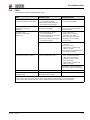
10.2 FUE6
A control lamp makes troubleshooting easier.
Fault Possible causes Remedial measure
Converter in operation.
Control lamp lights
red and green.
Excessive current consumption
of connected mac
hines.
Converter operates within the
permissible overload range.
Reduce the current consumption of
the connected machines.
Converter not in
operation. Control lam
p
lights red.
Line voltage interrupted.
Incorrect line voltage.
Converter starts automatically as
s
oon as the correct line voltage is
available (again).
Converter not in
operation. Control lamp
flashes red.
Short circuit in one of the
connected machines.
2-phase operation * in one of the
connected machines.
Mechanical defect in one of the
connected machines.
1. Carry out a reset:
Switch off the converter
and s
witch it on again.
2. Disconnect the connected
machines and check them.
3. Repeat reset.
S
hort circuit in converter.
1. Disconnect connected
machines.
2. Carry out a r
eset:
Switch off the converter and
switch it on again.
3. If the fault is not remedied, have
the machine repaired.
Converter not in operation.
Control lamp flashes red twice.
Converter has switched off due
to excess temperatur
e (> 85 °
C).
1. Allow the Converter to cool
down. Leave the converter
s
witched on to allow the
ventilator to keep running.
2. Carry out a reset:
Switch off the converter and
switch it on again.
Reduce the current consump-
tion of the connected machines.
Thumbwheel jammed. Thumbwheel dirty. Remove dirt.
Air cannot escape from the
ventilation slots.
Ventilator turns too slowly.
Ventilator does not turn.
Have the ventilator repaired. **
*
2-phase operation: The connected machine only uses 2 phases for current intake. Therefore, the engine does
not turn. The connected machine hums and heats up quickly due to the high current consumption.
**
Have these tasks carried out by the service department of your Wacker Neuson contact person.

11 Technical data
26 100_0103_td_0001.fm
11 Technical data
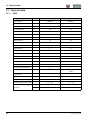
11.1 FUE1
Designation Unit FUE1/042/200W FUE1/120/200W
Item number 0008934 0610023
Rated current A 9,6 9,6
Rated voltage V 230 230
Rated frequency Hz 50 50
Rated power kVA 2,2 2,2
Phases ~ 1 1
Output current A 25 9
Output voltage V 42 120
Output frequency Hz 200 200
Output rated power kVA 1,8 1,8
Output phases ~ 3 3
Length mm 420 420
Width mm 325 325
Height mm 325 325
Length of power cable m 2,5 2,5
Weight kg 25 25
Plug CEE 7/7 (type EF) CEE 7/7 (type EF)
Number of plug receptacles 1 1
Plug receptacle type CEE 3P 32A 4h 50V 100-200Hz CEE 4P 16A 10h 50V 100-
300Hz
Class rating l l
Protection rating IP44 IP44
Storage temperature range °C -25 – +50 -25 – +50
Operating temperature range °C -15 – +40 -15 – +40
Sound pressure level L
pA
dB(A) < 70 < 70
Standards EN ISO 11201 EN ISO 11201

11 Technical data
100_0103_td_0001.fm 27
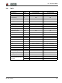
11.2 FUE2
Designation Unit FUE2/042/200W FUE2/250/200W
Item number 0008902 0610011
Rated current A 13 13
Rated voltage V 230 230
Rated frequency Hz 50 50
Rated power kVA 3 3
Phases ~ 1 1
Output current A 35 6
Output voltage V 42 250
Output frequency Hz 200 200
Output rated power kVA 2,6 2,6
Output phases ~ 3 3
Length mm 420 420
Width mm 325 325
Height mm 325 325
Length of power cable m 2,5 2,5
Weight kg 26,4 26,4
Plug CEE7/7(typeEF) CEE7/7(typeEF)
Number of plug receptacles 2 2
Plug receptacle type CEE 3P 32A 4h 50V 100-200Hz CEE 3P 32A 4h 50V 100-200Hz
Class rating l l
Protection rating IP44 IP44
Storage temperature range °C -25 – +50 -25 – +50
Operating temperature range °C -15 – +40 -15 – +40
Sound pressure level L
pA
dB(A) < 70 < 70
Standards EN ISO 11201 EN ISO 11201

11 Technical data
28 100_0103_td_0001.fm
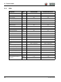
11.3 FUE6
Designation Unit FUE6/042/200W FUE6/042/200SC4CCEE
Item number 0610176 0610405
Rated current A 14,8 14,8
Rated voltage V 230 230
Rated frequency Hz 50 50
Rated power kVA 3,4 3,4
Phases ~ 1 1
Output current A 53 53
Output voltage V 42 42
Output frequency Hz 200 0 - 200
Output rated power kVA 3,9 3,7
Output phases ~ 3 3
Length mm 524 524
Width mm 325 325
Height mm 325 325
Length of power cable m 2,5 2,5
Weight kg 32,5 32,5
Plug CEE 7/7 (type EF) CEE 7/7 (type EF)
Number of plug receptacles 3 4
Plug receptacle type CEE 3P 32A 4h 50V 100-200Hz CEE 3P 32A 4h 50V 100-200Hz
Class rating l l
Protection rating IP44 IP44
Storage temperature range °C -25 – +50 -25 – +50
Operating temperature range °C -15 – +40 -15 – +40
Sound pressure level L
pA
dB(A) < 70 < 70
Standards EN ISO 11201 EN ISO 11201

11 Technical data
100_0103_td_0001.fm 29
11.4 KTU2
Designation Unit KTU2/042/200W
Item number 0008884
Rated current A 13
Rated voltage V 230
Rated frequency Hz 50
Rated power kVA 3
Phases ~ 1
Output current A 35
Output voltage V 42
Output frequency Hz 200
Output rated power kVA 2,6
Output phases ~ 3
Length mm 387
Width mm 395
Height mm 446
Length of power cable m 25
Weight kg 34,4
Plug CEE 7/7 (type EF)
Number of plug receptacles 3
Plug receptacle type CEE 3P 32A 4h 50V 100-200Hz
Class rating l
Protection rating IP44
Storage temperature range °C -25 – +50
Operating temperature range °C -15 – +40
Sound pressure level L
pA
dB(A) < 70
Standards EN ISO 11201

11 Technical data
30 100_0103_td_0001.fm
Extension cable
Only use permitted extension cables, see
chapter Safety.
Find the necessary stranded conductor cross-section of the extension cable in the following
table:
WARNING
Electrical voltage.
Injury from electric shock.
Check power cable and extension cable for damage.
Only use extension cables whose grounded conductor is connected to the plug and
coupling (only for equipment of class rating I, see chapter Technical data).
NOTICE
You can find the model designation and voltage of your equipment on the nameplate or
using the item no. from the chapter Technical data.
Equipment Voltage
[V]
Extension
[m]
Stranded conductor
cross-section
[mm
2
]
FUE 1/042/200W
FUE 1/120/200W
230 1~ < 31 1,5
<
52 2,5
<
82 4,0
FUE 2/042/200W
FUE 2/250/200W
230 1
~ < 23 1,5
<
38 2,5
<
61 4,0
FUE 6/042/200W
FUE 6/042/200W SC
FUE 6/042/
200W SC 4CEE
230 1
~ < 41 1,5
<
67 2,5
<
107 4,0
KTU 2/042/200W
KTU 2/250/200W
230 1
~ < 23 1,5
<
38 2,5
<
61 4,0

11 Technical data
100_0103_td_0001.fm 31
US Machine
Example
You utilize an FUE 2/250/200W and want to use an extension cable with a length of 25 m (82 ft).
The machine has an input voltage of 230 V.
According to the table, the extension cable must feature a cross-section area of 2.5 mm
2
(14 AWG).
Machine Voltage
[V]
Extension
ft
Cross-section area of
cable
AWG
FUE 1/042/200W
FUE 1/120/200W
230 1~ < 90 16
<
142 14
<
224 12
FUE 2/042/200W
FUE 2/250/200W
230 1
~ < 66 16
<
105 14
<
165 12
FUE 6/042/200W
FUE 6/042/200W SC
FUE 6/042/
200W SC 4CEE
230 1
~ < 105 16
<
184 14
<
290 12
KTU 2/042/200W
KTU 2/250/200W
230 1
~ < 66 16
<
105 14
<
165 12

12 Disposal
32 100_0000_0004.fm
12 Disposal
12.1 Disposal of old electrical and electronic equipment
Professional disposal of this machine avoids negative effects on human health and the environment,
helps with the targeted treatment of pollutants and makes it possible to recycle valuable raw materials.
For customers in EU countries
This machine is subject to the European directive for old electrical and electronic equipment (Waste
Electrical and Electronic Equipment (WEEE)), as well as the corresponding national laws. The WEEE
directive provides the framework for an EU-wide treatment of old electrical equipment.
The machine is marked with the following symbol of a crossed-out garbage bin. This
means that you do not dispose of the battery in normal household waste but that it must
be disposed of in a separate, environmentally friendly collection facility.
This unit is provided as a professional electrical tool exclusively for commercial use (a so-
called B2B device according to the WEEE directive). Unlike equipment mostly used in
private households (so-called B2C devices), this machine may therefore not be disposed of in some EU
countries, such as in Germany, at the collection points of public waste management organizations (e.g.
municipal collection stations). If there are any doubts, information regarding the different methods of
disposal for B2B electronic devices for each country can be obtained from the sales location, so that the
disposal takes place in accordance with the valid statutory provisions. There are also some notes to
follow in the sales contract or in the general Terms and Conditions of the sales location.
For customers in other countries
It is recommended that you do not dispose of the machine in normal household waste but rather in a
separate, environmentally friendly collection facility. National laws also may, under certain
circumstances, prescribe the separate disposal of electrical and electronic products. Correct disposal of
this machine in accordance with current national guidelines must be assured.

13 Glossary
100_0000_0005.fm 33
13 Glossary
Class rating
The class rating according to DIN EN 61140 identifies electrical machines in terms of safety measures
for the prevention of an electric shock. There are four class ratings:
Protection rating IP
The protection rating DIN EN 60529 indicates the suitability of electrical machines for certain
environmental conditions and also the protection against hazards.
The protection rating is specified with an IP code according to DIN EN 60529.
Class rating Significance
0 No special protection, other than the basic insulation.
No grounded conductor.
Plug connection without a grounded conductor contact.
I Connection of all conductive housing components to the grounded conductor.
Plug connection with a grounded conductor contact.
II Reinforced or double insulation (protective insulation).
No connection to the grounded conductor.
Plug connection without a grounded conductor contact.
III Machines are operated with a protective low voltage (<50 V).
Connection to the grounded conductor is not necessary.
Plug connection without a grounded conductor contact.
Code Significance of 1st digit:
Protection against contact with hazardous parts.
Protection against ingress of foreign bodies.
0 Not protected against contact.
Not protected against foreign bodies.
1 Protected against contact with the back of the hand.
Protected against large foreign bodies with a diameter of > 50 mm.
2 Protected against contact with a finger.
Protected against medium foreign bodies (diameter > 12.5 mm).
3 Protected against contact with a tool (diameter > 2.5 mm).
Protected against small foreign bodies (diameter of > 2.5 mm).
4 Protected against contact with a wire (diameter > 1 mm).
Protected against particle shape foreign bodies (diameter > 1 mm).
5 Protected against contact.
Protected against dust deposits inside.
6 Completely protected against contact.
Protected against dust ingress.
Code Significance of 2nd digit:
Protection against ingress of water
0 Not protected against water penetration.
1 Protected against vertically falling drip water.
2 Protected against angled falling drip water (15° inclination).
3 Protected against spray water (60° inclination).
4 Protected against splash water from all directions.
5 Protected against water jets (nozzle) from any angle.
6 Protected against powerful water jets (flooding).
7 Protected against temporary submersion in water.
8 Protected against continuous submersion in water.

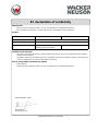
Original Declaration of Conformity
EC declaration of conformity
Manufacturer
Wacker Neuson Produktion GmbH & Co. KG, Wackerstraße 6, D-85084 Reichertshofen
This declaration of conformity is issued under the sole responsibility of the manufacturer.
Product
Guidelines and standards
We hereby declare that this product complies with the relevant provisions and requirements of the following
guidelines and standards:
2014/35/EU (2014-02), 2014/30/EU (2014-02), 2011/65/EU (2015-03), EN 61558-1 (2009-04), EN 61558-2-16
(2013-11), EN 61558-2-23 (2010-10), EN 61800-3 (2012-03)
Person responsible for technical documents
Robert Räthsel,
Wacker Neuson Produktion GmbH & Co. KG, Wackerstraße 6, D-85084 Reichertshofen
Product FUE1, FUE2, FUE6 KTU2
Product type Converter
Function of product Conversion of voltage and frequency
Item number 0008934, 0610023, 0008902,
0610011, 0610176, 0610405
0008884
Helmut Bauer
Managing Director
Reichertshofen, 1/2/17


-
 1
1
-
 2
2
-
 3
3
-
 4
4
-
 5
5
-
 6
6
-
 7
7
-
 8
8
-
 9
9
-
 10
10
-
 11
11
-
 12
12
-
 13
13
-
 14
14
-
 15
15
-
 16
16
-
 17
17
-
 18
18
-
 19
19
-
 20
20
-
 21
21
-
 22
22
-
 23
23
-
 24
24
-
 25
25
-
 26
26
-
 27
27
-
 28
28
-
 29
29
-
 30
30
-
 31
31
-
 32
32
-
 33
33
-
 34
34
-
 35
35
-
 36
36
-
 37
37
-
 38
38


Wacker Neuson KTU 2/042/200W Manual de usuario
- Tipo
- Manual de usuario
- Este manual también es adecuado para
en otros idiomas
Artículos relacionados
-
Wacker Neuson FUE 1/042/200W Manual de usuario
-
-
-
-
-
-
Wacker Neuson FUE 10/042/200 Manual de usuario
-
-
-