
Operator's manual
Converter
FUE 10
FUE-M/S
Model FUE, FUE-MS
Document 5000109972
Issue 05.2016
Version 05
Language en

Manufacturer
Wacker Neuson Produktion GmbH & Co. KG
Preußenstraße 41
80809 München
www.wackerneuson.com
Tel.: +49-(0)89-354 02-0
Fax: +49-(0)89-354 02-390
Translation of the original operator's manual in German
Copyright © 2016 Wacker Neuson Produktion GmbH & Co. KG
Printed in Germany
All rights are reserved, in particular the world-wide applicable copyright, right of duplication
and right of distribution.
This document may only be used by the recipient for the intended purpose. The document
may not be reproduced entirely or partially, or translated into any other language.
Reproduction or translation, even extracts thereof, only with written approval of Wacker
Neuson Produktion GmbH & Co. KG.
Any breach of the statutory provisions, in particular the protection of copyright, will lead to
civil and criminal prosecution.
Wacker Neuson Produktion GmbH & Co. KGis constantly working on the improvement of its
products as part of the technical further development. Therefore, we reserve the right to
make changes to the illustrations and descriptions in this documentation without incurring
any obligation to make changes to machines already delivered.
Errors excepted.
The machine on the cover may have special equipment (options).

5000109972IVZ.fm 3
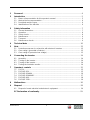
1 Foreword ....................................................................................................................4
2 Introduction ...............................................................................................................5
2.1 Means of representation for this operator's manual....................................................... 5
2.2 Wacker Neuson representative...................................................................................... 6
2.3 Described machine types............................................................................................... 6
2.4 Identification of the machine .......................................................................................... 6
3 Safety information ....................................................................................................7
3.1 General instructions....................................................................................................... 7
3.2 Operation ....................................................................................................................... 8
3.3 Safety checks................................................................................................................. 8
3.4 Maintenance................................................................................................................... 9
3.5 Transport........................................................................................................................ 9
3.6 Maintenance checks ...................................................................................................... 9
4 Technical data .........................................................................................................10
5Note ..........................................................................................................................12
5.1 Protective measures in conjunction with electronic inverters....................................... 12
5.2 Class rating I (grounded conductor)............................................................................. 12
5.3 Class rating III (protective low voltage)........................................................................ 13
6 Connecting the inverter ..........................................................................................14
6.1 Assembly...................................................................................................................... 14
6.2 Turning on the inverter................................................................................................. 14
6.3 Turning off the inverter................................................................................................. 14
6.4 Testing the insulation monitor...................................................................................... 14
7 Operator's controls .................................................................................................15
7.1 FUE 10......................................................................................................................... 15
7.2 FUE-M/S 85A............................................................................................................... 15
7.3 FUE-M/S 85A/460........................................................................................................ 16
7.4 FUE-M/S 85A/460RC................................................................................................... 17
7.5 FUE-M/S 86A............................................................................................................... 18
7.6 FUE-M/S 225A............................................................................................................. 19
8 Malfunctions ............................................................................................................20
9 Disposal ...................................................................................................................22
9.1 Disposal of waste electrical and electronic equipment................................................. 22
EC Declaration of conformity ................................................................................23

1Foreword
4
100_0000_0002.fm
1Foreword
This operator's manual contains important information and procedures for the
safe, proper and economic operation of this Wacker Neuson machine. Carefully
reading, understanding and observing is an aid to avoiding hazards, repair costs
and downtime, and therefore to increasing the availability and service life of the
machine.
This operator's manual is not a manual for extensive maintenance or repair work.
Such work should be carried out by Wacker Neuson service or by technically
trained personnel. The Wacker Neuson machine should be operated and main-
tained in accordance with this operator's manual. An improper operation or im-
proper maintenance can pose dangers. Therefore, the operator's manual should
be constantly available at the location of the machine.
Defective machine parts must be exchanged immediately!
If you have any questions concerning the operation or maintenance, a Wacker
Neuson contact person is always available.

2 Introduction
100_0000_0003.fm 5
2Introduction
2.1 Means of representation for this operator's manual
Warning symbols
This operator's manual contains safety information of the categories:
DANGER, WARNING, CAUTION, NOTICE.
They should be followed to prevent danger to life and limb of the operator or da-
mage to equipment and exclude improper service.
Notes
Hinweis: Complementary information will be displayed here.
Instructions
This symbol indicates there is something for you to do.
1. Numbered instructions indicate that you have to carry out something in a de-
fined sequence.
This symbol is used for lists.
GEFAHR
This warning notice indicates immediate hazards that result in serious injury or
even death.
Danger can be avoided by the following the actions mentioned.
WARNUNG
This warning notice indicates possible hazards that can result in serious injury
or even death.
Danger can be avoided by the following the actions mentioned.
VORSICHT
This warning notice indicates possible hazards that can result in minor injury.
Danger can be avoided by the following the actions mentioned.
ACHTUNG
This warning notice indicates possible hazards that can result in material dama-
ge.
Danger can be avoided by the following the actions mentioned.

2 Introduction
6
100_0000_0003.fm
2.2 Wacker Neuson representative
Depending on your country, your Wacker Neuson representative is your Wacker
Neuson service, your Wacker Neuson affiliate or your Wacker Neuson dealer.
You can find the addresses in the Internet at www.wackerneuson.com.
The address of the manufacturer is located at the beginning of this operator's
manual.
2.3 Described machine types
This operator's manual is valid for different machine types from a product range.
Therefore some figures can differ from the actual appearance of your machine.
It is also possible that the descriptions include components which are not a part
of your machine.
Details for the described machine types can be found in the chapter Technical
data.
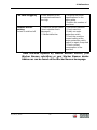
2.4 Identification of the machine
Nameplate data
The nameplate lists information that uniquely identifies your machine. This infor-
mation is needed to order spare parts and when requesting additional technical
information.
Enter the information of your machine into the following table:
Designation Your information
Group and type
Construction year
Machine no.
Version no.
Item no.

3 Safety information
100_0103_si_0002.fm 7
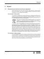
3 Safety information
for electronic frequency and voltage inverters
3.1 General instructions
Inverters may only be worked on independently by persons who
* are at least 18 years of age,
* are physically and mentally fit for this job,
* have been instructed in operating inverters and have proved their
abilities to the employer
* may be expected to carry out the job they are charged with carefully.
You must have been assigned to work on the inverters by the
company.
Inverters may only be operated according to their intended use, taking the oper-
ator's manual of the manufacturer and this safety information into account.
The persons charged with the operation of inverters must be made familiar with
the necessary safety measures relating to the machine. In case of extraordinary
uses, the employer shall give the necessary additional instructions.

3 Safety information
8
100_0103_si_0002.fm
3.2 Operation
The function of operation levers (operator's controls) and safety devices must not
be influenced or disabled.
You must ensure that the inverter is only attached to the voltage and frequency
indicated on the rating plate. Choose correct cross section for extension cord.
Only for FUE FUE-M/S 86A:
The frequency converter may only be connected to and operated with electric
power supplies that have < 30 mA residual current protective devices.
Only for FUE FUE-M/S 225A:
The frequency converter may only be connected to and operated with electric
power supplies that have < 300 mA residual current protective devices (type B).
For all other machines:
The frequency converter may only be connected to and operated with electric
power supplies that have < 30 mA residual current protective devices (type B).
Before you start up the inverter, make sure that the machine is in a vertically sta-
ble position to prevent it from tipping over, sliding away or falling down.
Do not insert or pull out the power plug as a means of turning the machine on or
off. The same applies to the machines to be connected to the inverter.
The power cable of the inverter must not be used to pull out the plug from the
plug receptacle.
Protect electric cable from heat, oil, and sharp edges.
Electrical equipment and material may only be used if they comply with opera-
tional and local safety requirements. They must be in proper condition and this
condition is to be maintained.
Do not operate the inverter in areas where explosions may occur.
3.3 Safety checks
Before starting operation, the operator has to check that all control and safety de-
vices are functioning properly.
Check electric cables for damage on a regular basis.
Inverters may only be operated with all safety devices installed.
If defects on the safety devices or other defects impairing the operational safety
of machine are observed, the supervisor must be informed immediately.
If there are defects jeopardizing operational safety, the machine has to be
switched off immediately.
Danger to life

3 Safety information
100_0103_si_0002.fm 9
3.4 Maintenance
Only use original spare parts. Alterations to this machine, incl. adjustments of the
frequency set by the manufacturer may only be carried out with the express per-
mission of Wacker Neuson. In case of non-observance, all liability shall be re-
fused.
Disconnect the inverter from the electrical power supply system before carrying
out maintenance and repair work.
Work on the electric parts of the machine may only be carried out by skilled tech-
nicians.
The green-yellow grounded conductor of the connecting cable must be longer so
that it will not be torn off if the strain relief fails. If interrupted, it can cause fatal
injury. After conducting repairs, check the grounded conductor for continuity.
As soon as maintenance and repair jobs have been completed, all safety devices
must be properly reinstalled.
Do not clean the machine with a high pressure washer.
3.5 Transport
For the loading and transportation of inverters with lifting gear, suitable sling
chains must be secured at the relevant fixing point.
When inverters are being transported in vehicles, precautions have to be taken
to ensure that they do not slip or fall over.
3.6 Maintenance checks
According to the conditions and frequency of use, inverters must be checked for
safe operation by a technician, for example at a Wacker Neuson service station,
at least once every 6 months and repaired if necessary.
Please observe the appropriate rules and regulations valid in your
country.

4 Technical data
10
100_0103_td_0002.fm
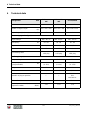
4 Technical data
Designation Unit
FUE 10/042/
200
FUE 10/250/
200
FUE-M/S 85A
Item no. 0610019 0610020 0108479
Width x Height x Depth
mm
(in)
500 x 550 x 580 500 x 550 x 580 500 x 500 x 550
Operating weight (mass) kg (lb) 87 87 42
Power supply value (input)
Input voltage V 400 - 415 3~ 400 - 415 3~ 400 - 415 3~
Frequency Hz 50 - 60 50 - 60 50 - 60
Input current A 24,5 24,5 13,7
Power kVA 17 17 9
Connecting cable
2.5 m with 32 A
CEE plug
2.5 m with 32 A
CEE plug
2.5 m with 16 A
CEE plug
Delivery (output)
Output voltage V 42 3~ 250 3~ 42 3~
Frequency
(programmable)
Hz
0 - 200
(0 -150)
0 - 200
(0 -150)
0 - 200
(0 - 150)
Output current A 145 25 85
Power kVA 10,5
10,5
6,18
Number of plug receptacles —
—
4 CEE 3P 32A 4H
50V
100-200 Hz
Protection class IP 54 IP 54 IP 44
Sound pressure level (L
PA
) at
operator's station
dB(A):
< 70 < 70 < 70

4 Technical data
100_0103_td_0002.fm 11
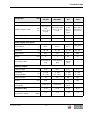
Designation Unit
FUE-M/S
85A/460
FUE-M/S
85A/460RC
FUE-M/S
86A
FUE-M/S
225A
Item no. 0008949 0008950 0610156 0108004
Width x Height x Depth
mm
(in)
500 x 550 x
580
(19.7 x 21.6
x 22.8)
500 x 550 x 580
(19.7 x 21.6 x
22.8)
500 x 550
x 580
(19.7 x
21.6 x
22.8)
600 x 700 x
700 (23.6 x
27.5 x 27.5)
Operating weight (mass) kg (lb) 42 (92.6) 42 (92.6) 42 (92.6) 150 (330.7)
Remote control — X — —
Power supply value (input)
Input voltage V 460 3~ 460 3~ 240 1~
400 - 415
3~
Frequency Hz 50 - 60 50 - 60 50 - 60 50 - 60
Input current A 13,7 13,7 37 28,9
Power kVA 9 9 8,9 20
Connecting cable
2.5 m without
plug
2.5 m without
plug
10 m
without
plug
—
Delivery (output)
Output voltage V 42 3~ 42 3~ 42 3~ 42 3~
Frequency
(programmable)
Hz
0 - 200
(0 - 150)
0 - 200
(0 - 150)
0 - 200
(0 - 150)
0 - 200
(0 - 150)
Output current A 85 85 86 225
Power kVA 6.18
6.18
6.3 16,3
Number of plug
receptacles
4 CEE 32 A 4 CEE 32 A
4 CEE
32 A
—
Protection class IP 44 IP 44 IP 44 IP 54
Sound pressure level (L
PA
)
at operator's station
dB(A)
< 70 < 70 < 70 < 70

5Note
12
100_0103_ot_0001.fm
5Note
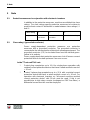
5.1 Protective measures in conjunction with electronic inverters
In addition to the protective measures, machines are divided into class
ratings. The class ratings specify protective measures to be taken to
prevent direct contact. A distinction is made between class ratings I, II
and III.
5.2 Class rating I (grounded conductor)
Power supply-dependent protective measures are protective
measures with a grounded conductor. The grounded conductor is
connected to the inactive bodies of electrical operating equipment. The
grounded conductor (PE) for insulated lines must be marked green-
yellow in its entirety.
Power supply-dependent protective measures shut off excess current
protective devices located upstream if an error occurs.
In the TT-net and TN-S-net:
* Protect plug receptacles up to 16 A for single-phase operation with
residual current protective devices that have a rated residual current of
< 30 mA.
* Protect 3-phase plug receptacles up to < 32 A with a residual current
protective device that have a rated residual current of < 30 mA. For
operation with electronic inverters, an "all-current sensitive residual
current protective device" with 30 mA must be used. If this is not
possible due to high stray currents (contingent on EMC line filters), a
differential current monitor must be employed.
Class rating I II III
Designation Grounded
conductor
Protective
insulation
Protective low voltage

5Note
100_0103_ot_0001.fm 13
Caution:
Due to the high stray current levels of the interference filter,
make sure that the inverter is only connected to one fault
current protective switch. This will prevent the fault current
protective switch from being triggered inadvertently.
5.3 Class rating III (protective low voltage)
Protective low voltage are rated voltages up to 50 V of AC current. The
protective low voltage prevents the build-up of a dangerous contact
voltage.
Safety transformers are permitted for generating protective low
voltages for which the low-voltage side has no conductive connection
to the power supplying network.
The inverter must be grounded with the grounded conductor
connection!

6 Connecting the inverter
14
100_0103_sf_0002.fm
6 Connecting the inverter
6.1 Assembly
Assembly instructions for the version without plug receptacle
Danger of electrocution!
Only a qualified electrician is permitted to assemble the plug and perform a safe-
ty check according to the directives in effect.
Observe the assembly instructions!
6.2 Turning on the inverter
Insert the plug into a suitable plug receptacle.
Only for FUE-M/S 85A/460 (RC):
Turn on the machine with the main switch.
* The green LED lights up when the machine door is closed.
For all machines:
Turn on the machine with the green ON button.
* The white LED lights up when the inverter is ready for operation.
* The green LED lights up if the temperature of the installed transformer
is OK. (A soft humming sound can be heard)
Turn on the connected vibrator with the circuit breaker.
6.3 Turning off the inverter
Turn off the connected vibrator with the circuit breaker.
Turn off the machine with the main switch or the red OFF button.
* All LEDs go out.
6.4 Testing the insulation monitor
Only for FUE 10/250/200:
The function of the insulation monitor can be tested with the touch
button with control lamp:
* The machine must turn off when the touch button with control lamp is
pressed.
* The green LED goes out.
Danger to life

7 Operator's controls
100_0103_cp_0003.fm 15
7 Operator's controls
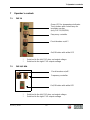
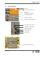
7.1 FUE 10
* Switched to the left: FUE does not output voltage
* Switched to the right: FUE outputs voltage
7.2 FUE-M/S 85A
* Switched to the left: FUE does not output voltage
* Switched to the right: FUE outputs voltage
Green LED for temperature indicator.
Touch button with control lamp for
insulation monitor
(only FUE 10/250/200)
Frequency controller
Circuit breaker on/off *
On/Off button with white LED
Frequency controller
Circuit breaker on/off *
On/Off button with white LED

7 Operator's controls
16
100_0103_cp_0003.fm
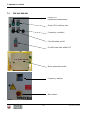
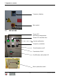
7.3 FUE-M/S 85A/460
Circuit breaker on/off
On/Off button with white LED
Green LED
transformer temperature
Green LED machine door
Frequency controller
Motor protection switch
Frequency display
Main switch

7 Operator's controls
100_0103_cp_0003.fm 17
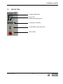
7.4 FUE-M/S 85A/460RC
Receiver
Green LED machine door
Green LED
transformer temperature
Circuit breaker on/off
On/Off button with white LED
Frequency controller
Stop radio communication
Start radio communication
Increase frequency
Turn on load
Turn off load
Reduce frequency
Motor protection switch

7 Operator's controls
18
100_0103_cp_0003.fm
7.5 FUE-M/S 86A
Frequency display
Main switch
Green LED
transformer temperature
Green LED machine door
Inverter malfunction
Frequency controller
Circuit breaker on/off
Preselection IR/AR
On/Off button with white LED
Motor protection switch

7 Operator's controls
100_0103_cp_0003.fm 19
7.6 FUE-M/S 225A
Inverter malfunction
Frequency controller
On/Off button with white LED
Main switch
Green LED
transformer temperature

8 Malfunctions
20
100_0103_ts_0003.fm
8 Malfunctions
Only for FUE-M/S 85 and FUE-M/S 86:
For all machines:
Malfunction Cause Remedy
FUE does not start
Green LED machine door
is not lit
* Machine door is open
* LED defective
* Close machine door
* Replace LED
Vibrators are not
working
* Frequency is too low
* Fuse has blown
* Increase frequency via
frequency controller
* Activate fuse
* Use other plug
receptacle
Malfunction Cause Remedy
FUE does not work
None of the LEDs are lit
* CEE plug is plugged in
to the receptacle,
* There is no voltage
present
* Fault current protective
switch in the worksite
switchgear assembly was
triggered
* Inverter module in the
FUE defective
Reset the fault current
protective switch
FUE does not work
None of the LEDs are lit
* Inverter module in the
FUE defective
* Have machine repaired
1
FUE does not work
White LED is lit, green
LED is not lit
The transformer
temperature is too high
* Turn machine off,
disconnect it from the
power supply and allow it
to cool down in the air
* Only use air as a cooling
medium
FUE is working
White or green or both
LEDs are not lit
LED defective Replace LED

8 Malfunctions
100_0103_ts_0003.fm 21
1
Have machine repaired by Wacker Neuson Service, your
Wacker Neuson subsidiary or your Wacker Neuson dealer.
Addresses can be found on the Wacker Neuson homepage.
FUE starts sluggishly Power demand of the
connected machines is
too high
* Observe the power
specifications on the
rating plate,
* Reduce the number of
machines
Vibrators are not
working
Socket is switched off
* Defective vibrator cable
(check whether line is
damaged)
* Vibrator defective
* Disconnect machine
* Check machine
* Switch on motor
protection switch
* Check the machine
current setting at the
motor protection switch,
switch on again if required
* Check current
consumption of the
machine

9 Disposal
100_0000_0004.fm
22
9 Disposal
9.1 Disposal of waste electrical and electronic equipment
Professional disposal of this machine avoids negative effects on human health
and the environment, helps with the targeted treatment of pollutants and makes
it possible to recycle valuable raw materials.
For customers in EU countries
This machine is subject to the European directive for old electrical and electronic
equipment (Waste Electrical and Electronic Equipment (WEEE)), as well as the
corresponding national laws. The WEEE directive provides the framework for an
EU-wide treatment of old electrical equipment.
The machine is marked with the following symbol of a crossed-out
garbage bin. This means that you do not dispose of the battery in
normal household waste but that it must be disposed of in a sepa-
rate, environmentally friendly collection facility.
This unit is provided as a professional electrical tool exclusively for
commercial use (a so-called B2B device according to the WEEE directive). Un-
like equipment mostly used in private households (so-called B2C devices), this
machine may therefore not be disposed of in some EU countries, such as in Ger-
many, at the collection points of public waste management organizations (e.g.
municipal collection stations). If there are any doubts, information regarding the
different methods of disposal for B2B electronic devices for each country can be
obtained from the sales location, so that the disposal takes place in accordance
with the valid statutory provisions. There are also some notes to follow in the sa-
les contract or in the general Terms and Conditions of the sales location.
For customers in other countries
It is recommended that you do not dispose of the machine in normal household
waste but rather in a separate, environmentally friendly collection facility. Natio-
nal laws also may, under certain circumstances, prescribe the separate disposal
of electrical and electronic products. Correct disposal of this machine in accor-
dance with current national guidelines must be assured.

Translation of the original Declaration of Conformity
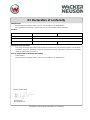
EC Declaration of conformity
Manufacturer
Wacker Neuson Produktion GmbH & Co. KG, Preussenstrasse 41, 80809 Munich
This declaration of conformity is issued under the sole responsibility of the manufacturer.
Product
Guidelines and standards
We hereby declare that this product complies with the requirements of the following guideline and standards:
2014/35/EU (2014-02), 2014/30/EU (2014-02), 2011/65/EU (2015-03), EN 61000-6-4 (2011-02), EN 61558-1
(2009-04), EN 61558-2-23 (2010-10)
Person responsible for technical documents
Robert Räthsel
Wacker Neuson Produktion GmbH & Co. KG, Preussenstrasse 41, 80809 Munich
Product FUE 10 FUE-M/S
Product type Inverter
Function of product Voltage and frequency conversion
Item number 06100019, 0610020 0108479, 0610156, 0108004
Helmut Bauer
Managing Director
Munich, 31.05.2016

-
 1
1
-
 2
2
-
 3
3
-
 4
4
-
 5
5
-
 6
6
-
 7
7
-
 8
8
-
 9
9
-
 10
10
-
 11
11
-
 12
12
-
 13
13
-
 14
14
-
 15
15
-
 16
16
-
 17
17
-
 18
18
-
 19
19
-
 20
20
-
 21
21
-
 22
22
-
 23
23
-
 24
24


Wacker Neuson FUE 10/042/200 Manual de usuario
- Tipo
- Manual de usuario
- Este manual también es adecuado para
En otros idiomas
Documentos relacionados
-
Wacker Neuson FUE 10/042/200 Manual de usuario
-
-
-
-
Wacker Neuson FUE 6/042/200 US Manual de usuario
-
Wacker Neuson FUE 1/042/200W Manual de usuario
-
-
-
-