VIA Technologies CM35-SC Manual de usuario
- Categoría
- Placas base
- Tipo
- Manual de usuario
Este manual también es adecuado para

CM30-SC
CM35-SC
Rev. A+
44400034
System Board Users Manual
Carte Mère Manuel Pour Utilisateur
System-Platine Benutzerhandbuch
Tablero Electrónico del Sistema Manual del
Usuario

Copyright
This publication contains information that is protected by copyright. No part of it may
be reproduced in any form or by any means or used to make any transformation/
adaptation without the prior written permission from the copyright holders. This
publication is provided for informational purposes only. The manufacturer makes no
representations or warranties with respect to the contents or use of this manual and
specifically disclaims any express or implied warranties of merchantability or fitness for
any particular purpose. The user will assume the entire risk of the use or the results of
the use of this document.
The manufacturer reserves the right to revise this publication and make
changes to its contents at any time, without obligation to notify any person or
entity of such revisions or changes.
Le fabricant se réserve le droit de revoir cette publication et deffecteur des
changements dans son contenu sans obligation dun préavis quelconque à qui
que ce soit.
Der Hersteller behält sich das Recht vor, den Inhalt dieses Handbuchs jederzeit
und ohne Benachrichtigung zu überarbeiten und abzuändern.
El fabricante reserva el derecho de corregir esta publicación y hacer cambios a
sus contenidos en cualquier tiempo, sin obligación de notificar a cualquier
persona o entidad de tales revisiones o cambios.
© 2000. All Rights Reserved.
Trademarks
Microsoft
®
MS-DOS
®
, Windows
TM
, Windows
®
95, Windows
®
98, Windows
®
98 SE,
Windows
®
2000 and Windows NT
®
4.0 are registered trademarks of Microsoft
Corporation. Intel
®
, Pentium
®
III and Celeron
TM
are registered trademarks of Intel
Corporation. VIA CyrixIII is a registered trademark of VIA Technologies, Inc. Award is a
registered trademark of Award Software, Inc. Other trademarks and registered trademarks
of products appearing in this manual are the properties of their respective holders.
Caution:
Danger of explosion if battery incorrectly replaced.
Replace only with the same or equivalent type recommended by the manufacturer.
Dispose of used batteries according to the battery manufacturers instructions.
FCC and DOC Statement on Class B
This equipment has been tested and found to comply with the limits for a Class B
digital device, pursuant to Part 15 of the FCC rules. These limits are designed to
provide reasonable protection against harmful interference when the equipment is
operated in a residential installation. This equipment generates, uses and can radiate
radio frequency energy and, if not installed and used in accordance with the instruction
manual, may cause harmful interference to radio communications. However, there is no
guarantee that interference will not occur in a particular installation. If this equipment
does cause harmful interference to radio or television reception, which can be
determined by turning the equipment off and on, the user is encouraged to try to
correct the interference by one or more of the following measures:
Reorient or relocate the receiving antenna.
Increase the separation between the equipment and the receiver.
Connect the equipment into an outlet on a circuit different from that to which the
receiver is connected.
Consult the dealer or an experienced radio TV technician for help.
Notice:
1. The changes or modifications not expressly approved by the par ty responsible for
compliance could void the user's authority to operate the equipment.
2. Shielded interface cables must be used in order to comply with the emission
limits.
English
Français
Deutsch
Español

Table of Contents / Table des Matières / Inhaltsverzeichnis / Tabla de Contenidos
Read Me First...........................................................................................................................................
Chapter 1 - Introduction
1.1 Features and Specifications............................................................................................
1.2 Package Checklist................................................................................................................
Chapter 2 - Hardware Installation
2.1 System Board Layout ......................................................................................................
2.2 Frequency Ratio Settings for Processors...............................................................
2.3 Jumper Settings for Selecting the CPUs Front Side Bus...............................
2.4 Jumper Settings for the Onboard Audio Codec...............................................
2.5 Jumper Settings for Clearing CMOS Data............................................................
2.6 Connectors..............................................................................................................................
Chapter 3 - Award BIOS Setup Utility
3.1 Entering the Award BIOS Setup Utility....................................................................
3.2 Setting the Date and Time..............................................................................................
3.3 Selecting the Hard Drive and Floppy Drive Type............................................
3.4 Selecting the Boot Sequence of the Drives..........................................................
3.5 Enabling the Processor Serial Number Function...............................................
3.6 Selecting the Power Lost Resume State..................................................................
3.7 Using the Suspend to RAM Function.......................................................................
3.8 Loading Fail-Safe Defaults/Optimized Defaults...................................................
3.9 Setting the Supervisor/User Password...................................................................
Chapter 4 - Supported Softwares
4.1 VIA Hardware Monitor...................................................................................................
4.2 VIA Service Pack................................................................................................................
4.3 Audio Drivers and Software Application..............................................................
4.4 Drivers and Utilities Installation Notes....................................................................
6
22
43
44
45
47
48
50
52
56
56
23
25
27
29
30
32
58
59
62
63
Note:
The users manual in the provided CD contains detailed information about the
system board. If, in some cases, some information doesnt match those shown in this
manual, this manual should always be regarded as the most updated version. To
view the users manual, insert the CD into a CD-ROM drive. The autorun screen
(Main Board Utility CD) will appear. Click Users Manual.
4

Introduction
1
4
Read Me First
This page contains a summary of the important notes that must be given special
attention to prior to using the system board.
1. Processor
The frequency ratio of some processors may have been locked by the
manufacturer. If you are using this kind of processor, setting an extended
ratio for the processor will have no effect. The system will instead use its
factory default ratio.
The frequency ratio of processors greater than 8x has been locked by
the manufacturer and will no longer have the flexibility of using extended
ratios. Therefore, the system will use the processors factory default ratio.
Selecting an external bus clock other than 66MHz, 100MHz or 133MHz
may result to the processors or systems instability and are not
guaranteed to provide better system performance.
2. System Memory - The system board supports both VCM and PC SDRAM
DIMMs. If you are using more than one DIMM, make sure you insert the
same type of DIMMs into the DIMM sockets. Using different types (VCM or
PC SDRAM) of DIMMs may cause problems.
3. 5VSB Power - If you are using the (1) Wake-On-LAN and/or (2) Wake-On-
Ring (internal modem) functions, the 5VSB power source of your power
supply must support ≥720mA. If you are using the Suspend to RAM function,
the 5VSB power source of your power supply must support ≥1A.
4. Drivers - Make sure to reboot the system after each driver installation.
Problems will occur if you reboot only after installing all the drivers.
Lisez Moi dAbord
Cette page contient un condensé des notes importantes quil faut prendre en
considération avant dutiliser la carte système.
1. Processeur
La taux de la fréquence de quelques processeurs au-dessus peut avoir
été blocké par le fabricant. Si vous utilisez ce genre de processeur, mettre
une taux étendue pour le processeur aura non effet. Le système utilisera
la taux défaut de lusine plutôt.
La taux de la fréquence de processeurs plus grand que 8x ont été
blocké par le fabricant et naura plus la flexibilité dutiliser de taux
étendus. Le système utilisera la taux défaut de lusine plutôt.
Le fait de sélectionner une horloge de bus externe autre que 66MHz,
100MHz ou 133MHz peut rendre le processeur ou le système instable et
ne garantit pas doffrir de meilleures performances système.
2. Mémoire Système - La carte système supporte à la fois les VCM et DIMM
PC SDRAM. Si vous utilisez plus dune DIMM, prenez soin dinsérer le même
type de DIMM dans les logements DIMM. Le fait dutiliser des DIMM de
type différents (VCM ou PC SDRAM) peut engendrer des problèmes.
3. Alimentation 5VSB - Si vous utilisez les fonctions (1) Eveil LAN (Wake-On-
LAN) et/ou (2) Eveil Sonnerie (Wake-On-Ring) (modem interne), la source
dalimentation 5VSB de votre bloc dalimentation doit supporter ≥720mA. Si
vous utilisez les fonctions Suspension sur RAM, la source dalimentation 5VSB
de votre bloc dalimentation doit supporter ≥1A.
4. Pilotes - Prenez soin de réamorcer le système après linstallation de chaque
pilote. Des problèmes apparaîtront si vous réamorcez seulement après
linstallation de tous les pilotes.
English
Français

1
Introduction
5
Lesen Sie Diese Anleitung Zuerst Durch
Auf dieser Seite ist eine Zusammenfassung aller Hinweise enthalten, die vor der
Benutzung der Systemplatine unbedingt beachtet werden müssen.
1. Prozessor
Die Frequenzrate von einige, Prozessoren konnte vielleicht von Hersteller
gesperrt sein. Wenn Sie diese Art von Prozessor benutzen, wird das
eingeben eine erweiterte Rate für den Prozessor keine Wirkung haben.
Das System wird stattdessen den Standard Fabrikrate benutzen.
Die Frequenzrate von Prozessoren, welche größer als 8x sind, sind von
Hersteller gesperrt, und werden nicht länger die erweiterten Raten
Flexibilität haben. Das System wird stattdessen den Standard Fabrikrate
benutzen.
Ein Auswählen eines Bus-Taktgebers, welcher von den Frequenzen 66MHz,
100MHz oder 133MHz abweicht, kann eine Unstabilität des Prozessors
oder des Systems verursachen. Eine bessere Betriebsleistung des Systems
kann durch eine solche Einstellung nicht gewährleistet werden.
2. Systemspeicher - Die Systemplatine unterstützt die VCM- sowie die PC-
SDRAM-DIMMs. Falls mehr als ein DIMM verwendet wird, darf nur derselbe
Typ der DIMMs in die DIMM-Steckfassungen eingesetzt werden, da andere
DIMM-Typen (VCM oder PC SDRAM) zu Konflikten führen können.
3. 5VSB-Stromversorgung - Falls Sie die (1) Wake-On-LAN- und/oder (2)
Wake-On-Ring-Funktionen (internes Modem) anwenden, unterstützt die 5VSB-
Stromquelle Ihres Netzgerätes eine Leistung von ≥720 mA. Falls Sie die
Suspendieren-auf-RAM-Funktion, unterstützt die 5VSB-Stromquelle Ihres
Netzgerätes eine Leistung von ≥1A.
4. Treiber - Das System muß nach jedem Installieren eines Treibers neugestartet
werden. Probleme werden nur dann auftreten, wenn das System nach dem
Installieren aller Treiber neugestartet wird.
Leer Me Primero
Esta pagina contiene informationes importantes que se deben prestar mucha
attention antes del uso de la tabla de sistema
1. Procesador
La proporción de frecuencia de algunos procesadores de arriba uede
que ha sido bloqueada por el fabricante. Si usted está utilizando esta
clase de procesador, configurando la ración para el procesador no
tendrá efecto. El sistema en vez utilizará la proporción implícita de la
fábrica.
La ración de frecuencia de los procesadores mayor que 8x ha sido
bloquada por el fabricante y ya no tendrá la flexibilidad de utilizar las
proporciones extendidas. El sistema utiliza su proporción implícita de la
fábrica.
Seleccionando un reloj de bus externo otro que 66MHz, 100MHz o
133MHz puede resultar la inestabilidad del procesador o del sistema y
no son garantizados para proveer una mejor ejecución de sistema.
2. Memoria de Sistema - El tabla del sistema suporta ambos, el VCM y el PC
SDRAM DIMMs. Si usted está utilizando más que un DIMM, asegura de
insertar el mismo tipo de DIMM dentro del encaje de DIMM. Utilizando
diferentes tipos (VCM o PC SDRAM) de DIMM puede causar problemas.
3. 5VSB Potencia - Si estas usando las funciones de (1) Wake-On-LAN y/o
si se esta usando el (2) Wake-On-Ring (que es el modem interno), el 5VSB
potencia debe soportar una corrient (>) mas grande que ≥720mA. Si estas
usando las funciones de Suspender a RAM, el 5VSB potencia debe soportar
una corrient (>) mas grande que ≥1A.
4. Drivers - Asegurese de reboot o rebootear el sistema cada vez que se
instala un nuevo Driver. Problemas suelen ocurrir si se rebootea solo una
vez despuez de haber terminado con las instalacionens de todos los drivers.
Deutsch
Español

Introduction
1
6
Expansion Slots
The CM35-SC system board is equipped with 1 shared AGP / DFP (Digital Flat
Panel) slot while CM30-SC is only equipped with the DFP slot.
The AGP slot on the CM35-SC system board is a universal AGP slot. AGP is an
interface designed to support high performance 3D graphics cards. It utilizes a
1.1 Features and Specifications
Caractéristiques et Spécifications
Leistungsmerkmale und Technische Daten
Características y Especificaciones
1.1.1 Features
Chipset
VIA
®
8604/82C686A AGPset (PL133) - CM30-SC
VIA
®
8605/82C686A AGPset (PM133) - CM35-SC
Processor
The system board is equipped with a switching voltage regulator that
automatically detects 1.30V to 3.5V.
Pentium
®
III FCPGA 133MHz FSB (533EB-933EB) or 100MHz FSB (500E-
850E) processor
Celeron
TM
66MHz FSB: FCPGA (566MHz-700MHz) or PPGA (300A-
533MHz) processor
VIA CyrixIII processor
System Memory
Up to 1GB using VCM (Virtual Channel Memory) or PC SDRAM DIMM
(unbuffered or registered)
Two 168-pin DIMM sockets
Uses x64 PC SDRAM, 3.3V
: PC-66 SDRAM DIMM for 66MHz FSB processors
: PC-100 SDRAM DIMM for 100/66MHz FSB processors
: PC-133 SDRAM DIMM for 133MHz FSB processors
Chapter 1 - Introduction
Introduction
Einleitung
Introducción
English
Note:
If you are using more than one DIMM, make sure you insert the same type
of DIMMs into the DIMM sockets. Using different types (VCM or PC
SDRAM) of DIMMs may cause problems.
DIMMs
2MBx64
4MBx64
8MBx64
Memory Size
16MB
32MB
64MB
DIMMs
16MBx64
32MBx64
64MBx64
Memory Size
128MB
256MB
512MB

1
Introduction
7
dedicated pipeline to access system memory for texturing, z-buffering and alpha
blending. The universal AGP slot supports AGP 2x with up to 533MB/sec.
bandwidth and AGP 4x with up to 1066MB/sec. bandwidth for 3D graphics
applications. AGP in this system board will deliver faster and better graphics to
your PC.
Both system boards are also equipped with 2 dedicated PCI slots and 1 shared
AMR/ISA slot. AMR (Audio/Modem Riser) is an interface designed for installing
an audio riser card, modem riser card or audio/modem riser card that is
compliant to the AMR specification.
Onboard Graphics Features
Integrated Savage4 2D/3D/Video accelerator
- Shares 1MB of the system memory
- Optimized Shared Memory Architecture (SMA)
- Full AGP 4x, including sideband addressing and execute mode
- High quality DVD video playback
3D rendering features
- 32-bit true color rendering
- MPEG-2 video textures
2D hardware acceleration features
Motion video architecture
Software drivers
- Windows
®
95/98/2000
- Windows NT
®
4.0
Onboard Audio Features
Supports Microsoft
®
DirectSound/DirectSound 3D
AC97 supported with full duplex, independent sample rate converter for
audio recording and playback
ATX Double Deck Ports (PC 99 color-coded connectors)
2 USB ports
1 NS16C550A-compatible DB-9 serial port
1 DB-15 VGA por t
1 SPP/ECP/EPP DB-25 parallel port
1 mini-DIN-6 PS/2 mouse port
1 mini-DIN-6 PS/2 keyboard port
1 game/MIDI port
3 audio jacks: line-out, line-in and mic-in
Connectors
1 connector for 2 additional external USB ports
1 9-pin connector for 1 external serial port
1 connector for IrDA interface
2 IDE connectors
1 floppy drive interface supports up to two 2.88MB floppy drives
1 20-pin ATX power supply connector
1 Wake-On-LAN connector
1 Wake-On-Ring connector
CPU and chassis fan connectors
3 internal audio connectors (AUX-in, CD-in and TAD)
PCI Bus Master IDE Controller
Two PCI IDE interfaces support up to four IDE devices
Supports ATA/33 or ATA/66 hard drives

Introduction
1
8
PIO Mode 3 and Mode 4 Enhanced IDE (data transfer rate up to 16.6MB/
sec.)
Bus mastering reduces CPU utilization during disk transfer
Supports ATAPI CD-ROM, LS-120 and ZIP
IrDA Interface
The system board is equipped with an IrDA connector for wireless connectivity
between your computer and peripheral devices. It supports peripheral devices
that meet the HPSIR or ASKIR standard.
USB Ports
The system board supports 4 USB ports. Two onboard USB ports are located
at the ATX double deck ports of the board. The J23 connector on the system
board allows you to connect the optional 3rd and 4th USB ports. These
optional USB ports, which are mounted on a card-edge bracket, will be
provided as an option. USB allows data exchange between your computer and
a wide range of simultaneously accessible external Plug and Play peripherals.
BIOS
Award BIOS, Windows
®
95/98/2000 Plug and Play compatible
Supports SCSI sequential boot-up
Flash EPROM for easy BIOS upgrades
Supports DMI 2.0 function
2Mbit flash memory
Desktop Management Interface (DMI)
The system board comes with a DMI 2.0 built into the BIOS. The DMI utility in
the BIOS automatically records various information about your system
configuration and stores these information in the DMI pool, which is a part of
the system board's Plug and Play BIOS. DMI, along with the appropriately
networked software, is designed to make inventory, maintenance and
troubleshooting of computer systems easier.
1.1.2 System Health Monitor Functions
The system board is capable of monitoring the following system health
conditions.
Monitors CPU/system temperature and overheat alarm
Monitors VCORE/3.3V/5V/12V/2.5V voltages and failure alarm
Monitors CPU/chassis fan speed and failure alarm
Automatic CPU and chassis fans on/off control
Read back capability that displays temperature, voltage and fan speed
If you want a warning message to pop-up or a warning alarm to sound when an
abnormal condition occurs, you must install the VIA Hardware Monitor utility.
This utility is included in the CD that came with the system board. Refer to the
VIA Hardware Monitor section in chapter 4 for more information.
1.1.3 Intelligence
Automatic CPU/Chassis Fan Off
The CPU and chassis fans will automatically turn off once the system enters the
Suspend mode.
Dual Function Power Button
Depending on the setting in the Soft-Off By PWRBTN field of the Power
Management Setup, this switch will allow the system to enter the Soft-Off or
Suspend mode.

1
Introduction
9
Wake-On-Ring
This feature allows the system that is in the Suspend mode or Soft Power Off
mode to wake-up/power-on to respond to calls coming through an internal or
external modem.
Important:
If you are using a modem add-in card, the 5VSB power source of your
power supply must support a minimum of
≥
720mA.
RTC Timer to Power-on the System
The RTC installed on the system board allows your system to automatically
power-on on the set date and time.
Wake-On-LAN
The Wake-On-LAN function allows the network to remotely wake up a Soft
Power Down (Soft-Off) PC. Your LAN card must support the remote wakeup
function.
Important:
The 5VSB power source of your power supply must support
≥
720mA
(minimum).
AC Power Failure Recovery
When power returns after an AC power failure, you may choose to either
power-on the system manually, let the system power-on automatically or return
to the state where you left off before power failure occurs. Refer to Selecting
the Power Lost Resume State in chapter 3 for more information.
ACPI STR
The system board is designed to meet the ACPI (Advanced Configuration and
Power Interface) specification. ACPI has energy saving features that enables PCs
to implement Power Management and Plug-and-Play with operating systems that
support OS Direct Power Management. Currently, only Windows
®
98/2000
supports the ACPI function. ACPI when enabled in the Power Management Setup
will allow you to use the Suspend to RAM function.
With the Suspend to RAM function enabled, you can power-off the system at
once by pressing the power button or selecting Standby when you shut down
Windows
®
98/2000 without having to go through the sometimes tiresome
process of closing files, applications and operating system. This is because the
system is capable of storing all programs and data files during the entire
operating session into RAM (Random Access Memory) when it powers-off. The
operating session will resume exactly where you left off the next time you
power-on the system. Refer to Using the Suspend to RAM Function in chapter
3 for more information.
Important:
The 5VSB power source of your power supply must support
≥
1A.
Virus Protection
Most viruses today destroy data stored in hard drives. The system board is
designed to protect the boot sector and partition table of your hard disk drive.

Introduction
1
10
Note:
Si vous utilisez plus dune DIMM, prenez soin dinsérer le même type de
DIMM dans les logements DIMM. Le fait dutiliser des DIMM de type
différents (VCM ou PC SDRAM) peut engendrer des problèmes.
Mémoire
16MB
32MB
64MB
Mémoire
128MB
256MB
512MB
Logements dExtension
La carte système CM35-SC est équipée dun créneau partagé AGP / DFP
(Digital Flat Panel) alors que la carte CM30-SC est seulement équipée dun
créneau DFP. Le créneau AGP sur la carte système CM35-SC est un créneau
AGP universel. AGP est une interface conçue pour supporter des cartes
graphiques 3D de haute performance. Elle utilise un pipeline dédié pour accéder
à la mémoire système pour le texturage, le z-buffering et le mélange alpha. Le
slot AGP universel supporte 2x AGP avec une bande passante allant jusquà
533Mo/sec et 4x AGP avec une bande passante allant jusquà 1066Mo/sec pour
les applications graphiques 3D. AGP sur cette carte système offrira des
graphiques meilleurs et plus rapide à votre PC.
Les deux cartes systèmes sont aussi équipées de deux créneaux PCI dédiés et
dun créneau AMR/ISA partagé. AMR (Riser Audio/Modem) est dune interface
destinée à linstallation dune carte audio riser, carte modem riser ou dune carte
audio/modem réhausseur conforme aux spécifications AMR.
1.1.1 Caractéristiques
Chipset
VIA
®
8604/82C686A AGPset (PL133) - CM30-SC
VIA
®
8605/82C686A AGPset (PM133) - CM35-SC
Processeur
La carte système est équipée dun régulateur de commutation de voltage qui
détecte automatiquement de 1.30V à 3.5V.
Pentium
®
III FCPGA 133MHz FSB (533EB-933EB) ou 100MHz FSB (500E-
850E) processeur
Celeron
TM
66MHz FSB: FCPGA (566MHz-700MHz) ou PPGA (300A-
533MHz) processeur
VIA CyrixIII
processeur
Mémoire Système
Supporte jusquà 1Go de mémoire utilisant VCM (Virtual Channel Memory)
ou PC SDRAM DIMM (tampon ou enregistrées)
2 sockets DIMM 168 broches.
Utilise x64 PC SDRAM, 3.3V
- PC-66 SDRAM DIMM pour processeurs 66MHz FSB
- PC-100 SDRAM DIMM pour processeurs 100/66MHz FSB
- PC-133 SDRAM DIMM pour processeurs 133MHz FSB
Français
DIMMs
2MBx64
4MBx64
8MBx64
DIMMs
16MBx64
32MBx64
64MBx64

1
Introduction
11
Caractéristiques Graphiques sur Carte
Laccélérateur 2D/3D/Video Intégré Savage4
- Partage 1Mo de mémoire système
- Architecture de Mémoire Partagée Optimisée (SMA)
- Full AGP 4x, comprenant ladressage par bande latérale et le mode
exécuter
- Lecture de DVD vidéo de haute qualité
Fonctionnalités de rendu 3D
- Rendu couleur vraie 32 bits
- Textures vidéo MPEG-2
Fonctionnalités daccélération de matérielle 2D
Architecture danimation vidéo
Logiciels Pilotes
- Windows
®
95/98/2000
- Windows NT
®
4.0
Caractéristiques Audio sur Carte
Supporte DirectSound de Microsoft
®
/DirectSound 3D de Microsoft
®
AC97 supporté avec full duplex, convertisseur de vitesse déchantillonnage
indépendant pour enregistrement audio et lecture.
Ports Double Module ATX (Connecteurs PC 99 avec codes couleur)
2 ports USB
1 port série DB-9 compatible NS16C550A
1 port VGA DB-15
1 port parallèle DB-25 SPP/ECP/EPP
1 port souris PS/2 mini-DIN-6
1 port clavier PS/2 mini-DIN-6
1 port jeu/MIDI
3 prises audio: ligne de sortie, ligne dentrée et entrée micro
Connecteurs
1 connecteur pour 2 ports USB supplémentaires
1 connecteur 9 broches pour port série externe
1 connecteur pour interface IrDA
2 connecteurs IDE
1 connecteur de lecteur de disquettes supportant jusquà deux lecteurs de
disquettes de 2.88Mo
1 connecteur dalimentation ATX 20 broches
1 connecteur Wake-On-LAN
1 connecteur Wake-On-Ring
Connecteurs de ventilateurs de CPU et de châssis ventilateur
3 connecteurs audio internes (AUX-in, CD-in et TAD)
Contrôleur IDE de BUS Maître PCI
Deux interfaces PCI IDE supportant jusquà quatre matériels IDE
Supporte des disques durs ATA/33 ou ATA/66
IDE Améliorés Mode 3 et 4 PIO (vitesse de transfert de données allant
jusquà 16.6Mo/sec.)
La gestion de Bus réduit lutilisation du CPU pendant les transferts sur disque
Supporte les CD-ROM ATAPI, LS-120 et ZIP
Interface IrDA
La carte système est équipée dun connecteur IrDA pour les connexions sans fil
entre votre ordinateur et des périphériques. Il supporte les périphériques qui
sont conformes aux standards HPSIR ou ASKIR.

Introduction
1
12
Ports USB
La carte système supporte 4 ports USB. Deux ports USB sur carte se trouvent
sur les ports double deck ATX de la carte. Le connecteur J23 situé sur la carte
système vous permet de connecter les 3
ème
et 4
ème
ports USB optionnels. Ces
ports USB optionnels, qui sont montés sur un support latéral de carte, vous
seront fournis en option. USB permet léchange de données entre votre
ordinateur et un grande éventail de périphériques externes Plug and Play
accessibles simultanément.
BIOS
Compatible avec Award BIOS, Windows
®
95/98/2000 Plug and Play
Supporte lamorçage séquentiel SCSI
EPROM Flash pour une mise à niveau facile du BIOS
Supporte la fonction DMI 2.0
Mémoire Flash 2Mbit
Interface de Gestion de Bureau (DMI)
La carte système est livrée avec un DMI 2.0 intégré au BIOS. Lutilitaire DMI
dans le BIOS enregistre automatiquement diverses informations concernant la
configuration de votre système et stocke ces informations dans la liste DMI, qui
est une partie du BIOS Plug and Play de la carte système. DMI, accompagné
du logiciel en réseau approprié, est conçu pour rendre linventaire, lentretien et
le dépannage du système de lordinateur plus facile.
1.1.2 System Health Monitor Fonctions
La carte système est capable de gérer les conditions de santé système
suivantes.
Alarme de température et de surchauffe de CPU/système de Moniteurs
Alarme déchec et de voltage VCORE/3.3V/5V/12V/2.5V de moniteurs
Alarme déchec et de vitesse de ventilateur de CPU/châssis de moniteurs
Contrôle de marche/arrêt automatique de ventilateur de CPU/châssis
Capacité de relecture affichant la température, le voltage et la vitesse de
ventilateur
Si vous désirez quun message davertissement apparaisse ou quune alarme
retentisse lorsque quune condition anormale se produit, vous devez installer VIA
Hardware Monitor. Cet utilitaire est compris dans le CD qui est livré avec la
carte système. Reportez vous à la section concernant Utilitaire VIA Hardware
Monitor dans le chapitre 4 pour de plus amples informations.
1.1.3 Intelligence
Arrêt automatique de Ventilateur de CPU/Châssis
Les ventilateurs de CPU et de châssis sarrêteront automatiquement une fois que
le système est entré en mode Suspension.
Bouton dAlimentation à Fonction Double
En fonction du paramétrage dans le champ Soft-Off By PWRBTN du
Programme dInstallation de la Power Management Setup, ce commutateur
permettra à votre système dentrer en mode Soft-Off ou Suspension.

1
Introduction
13
Wake-On-Ring
Cette caractéristique permet au système qui se trouve en mode Suspension ou
en mode Arrêt Alimentation par Logiciel de se réveiller/sallumer pour répondre
à des appels provenant dun modem interne ou externe.
Important:
Si vous utilisez une carte complémentaire de modem, la source
dalimentation de 5VSB de votre boîtier dalimentation doit supporter un
minimum de
≥
720mA.
Minuterie RTC pour Allumer le Système
Le RTC installé sur la carte système permet à votre système de sallumer
automatiquement à une date et heure présélectionnée.
Wake-On-LAN
La fonction Wake-On-LAN permet au réseau de réveiller à distance un PC Mis
Hors Tension par Logiciel (Soft Power Down ou Soft- Off). Votre carte LAN
doit supporter la fonction de réveil à distance.
Important:
La source dalimentation 5VSB de votre boîtier dalimentation doit supporter
≥
720mA (minimum).
Récupération après Défaillance dAlimentation CA
Quand lalimentation revient après une défaillance dalimentation CA, vous pouvez
choisir dallumer le système manuellement, de laisser le système sallumer
automatiquement ou de retourner à létat que vous aviez quitté avant que la
défaillance dalimentation se produise. Reportez vous à Choisir létat de
Redémarrage Après Coupure de Courant dans le chapitre 3 pour plus
dinformations.
ACPI STR
La carte système est conçue de façon à être conforme aux spécifications ACPI
(Configuration Avancée et Interface dAlimentation). ACPI comporte une fonction
déconomie dénergie qui permet aux PC de mettre en uvre la Gestion
dAlimentation et Plug and Play avec des systèmes dexploitation qui supportent
la Gestion dAlimentation Directe de Système dExploitation. Actuellement,
seulement Windows
®
98/2000 supporte la fonction ACPI. Quand ACPI est activé
dans le Programme de Power Management Setup, cela vous permet dutiliser la
fonction de Suspension sur RAM.
Quand la fonction de Suspension sur RAM est activée, vous pouvez éteindre le
système immédiatement en appuyant sur le bouton dalimentation ou en
sélectionnant Veille quand vous éteignez Windows
®
98/2000 sans avoir à
passer par le processus quelquefois ennuyeux de fermeture des fichiers, des
applications et du système dexploitation. Ceci est du au fait que le système est
capable de stocker tous les fichiers programmes et de données pendant toute la
session dutilisation dans la RAM (Mémoire à Accès Aléatoire) lorsque quil
séteint. La session dutilisation reprendra exactement où vous lavez laissée la
prochaine fois que vous allumerez le système. Reportez vous à Utilisation de la
Fonction de Suspension sur RAM dans le Chapitre 3 pour plus dinformations.
Important:
La source dalimentation 5VSB de votre boîtier dalimentation doit supporter
≥
1A.

Introduction
1
14
Erweiterungssteckfasssungen
Die CM35-SC-Systemplatine ist mit 1 gemeinsam benutzten AGP/DFP-
Steckfassung (digitaler Flachbildschirm) ausgestattet, während die CM30-SC nur
eine DFP-Steckfassung besitzt. Die AGP-Steckfassung auf der CM35-SC-
Systemplatine ist eine universelle AGP-Steckfassung. AGP ist eine Schnittstelle, die
zum Unterstützen der Hochleistungs-3D-Grafikkarten bestimmt ist und die für
den Zugriff zum Speicher für die Textur, das Z-Puffern und Alpha-Mischen eine
dedizierte Leitung verwendet. Für die 3D-Grafikanwendungen unterstützt die
universelle AGP-Steckfassung einen AGP 2x mit einer Bandweite von bis zu
533MB/Sek. sowie einen AGP 4x mit einer Bandweite von bis zu 1066MB/Sek.
Durch den AGP in diesem System werden bessere Grafiken schneller an Ihren
PC übertragen.
Beide Systemplatinen sind ebenfalls mit 2 dedizierten PCI-Steckfassungen und
einer gemeinsam benutzten AMR/ISA-Steckfassung ausgestattet. AMR (Audio-/
Modem-Riser) ist eine Schnittstelle für die Installation einer Audio-Riserkarte, einer
Modem-Riserkarte oder einer Audio-/Modem-Riserkarte, die der AMR-Vorschrift
entspricht.
Speicher
16MB
32MB
64MB
Speicher
128MB
256MB
512MB
Hinweis:
Falls mehr als ein DIMM verwendet wird, darf nur derselbe Typ der DIMMs
in die DIMM-Steckfassungen eingesetzt werden, da andere DIMM-Typen
(VCM oder PC SDRAM) zu Konflikten führen können.
Deutsch
Protection contre les Virus
La plupart des virus détruisent les données stockées sur les disques durs. La
carte système est conçue pour protéger le secteur damorçage et la table de
partition de votre disque dur.
1.1.1 Leistungsmerkmale
Chipset
VIA
®
8604/82C686A AGPset (PL133) - CM30-SC
VIA
®
8605/82C686A AGPset (PM133) - CM35-SC
Prozessor
Die Systemplatine ist mit einem Spannungsregler ausgestattet, durch welchen
automatisch Spannungen von 1,30V bis 3,5V festgestellt werden.
Pentium
®
III FCPGA 133MHz FSB (533EB-933EB) oder 100MHz FSB (500E-
850E) prozessor
Celeron
TM
66MHz FSB: FCPGA (566MHz-700MHz) oder PPGA (300A-
533MHz) prozessor
VIA CyrixIII prozessor
Systemspeicher
Unterstützt einen Speicher von bis zu 1GB mit ohne VCM (Virtual Channel
Memory) oder PC SDRAM DIMM (Pufferspeicher oder registriert)
2 DIMM-Fassungen mit 168poligem Anschlußstecker.
Funktioniert mit ´64-PC-SDRAM, 3,3V
- PC-66 SDRAM DIMM für 66MHz-FSB-Prozessore
- PC-100 SDRAM DIMM für 100/66MHz-FSB-Prozessore
- PC-133 SDRAM DIMM für 133MHz-FSB-Prozessore
DIMMs
2MBx64
4MBx64
8MBx64
DIMMs
16MBx64
32MBx64
64MBx64

1
Introduction
15
Grafikmerkmale auf Platine
Integrierter Savage4 2D/3D/Video-Beschleuniger
- Gemeinsame Benutzung von 1 MB des Systemspeichers
- Optimierte Architektur des gemeinsam benutzten Speichers (SMA)
- Volles AGP 4x, einschl. Seitenbandadressierung und Ausführungsmodus
- Hochwertige Wiedergabe des DVD-Videos
3D-Rendering-Merkmale
- 32-Bit-Rendering naturgetreuer Farben
- MPEG-2-Videotextur
Merkmale der 2D-Hardware-Beschleunigung
Architektur für Bewegungsvideo
Softwaretreiber
- Windows
®
95/98/2000
- Windows NT
®
4.0
Audiomerkmale auf Platine
Unterstützung des Microsoft
®
DirectSound/DirectSound 3D
AC97 mit Unterstützung des Vollduplexbetriebs, unabhängigem
Abtastratenumwandler für die Aufnahme und Wiedergabe
ATX-Zweietagen-Anschlüsse (PC 99 mit farbkodierten Steckverbindungen)
2 USB-Anschlüsse
1 serieller DB-9-Anschluß, kompatibel mit NS16C550A
1 DB-15-VGA-Anschluß
1 DB-25-Parallelanschluß SPP/ECP/EPP
1 Mini-DIN-6-Anschluß für eine PS/2-Maus
1 Mini-DIN-6-Anschluß für eine PS/2-Tastatur
1 Spiel-/MIDI-Anschluß
3 Audio-Anschlußbuchsen: Ausgangsleitung, Eingangsleitung und Mikrofon-
Eingang
Anschlußstecker
1 Anschlußfassung für 2 zusätzliche externe USB-Anschlüsse
Ein 9poliger Anschlußstecker für den externen seriellen Anschluß
1 Anschluß für die IrDA-Schnittstelle
2 IDE-Anschlüsse
Unterstützung von bis zu zwei 2,88MB-Floppylaufwerken durch einen
Floppylaufwerksanschluß
1 20poliger Anschlußstecker für das ATX-Netzgerät
1 Anschlußstecker für Wecken durch LAN
1 Anschlußstecker für Wecken durch Ring
CPU- und Chassis-ventilator-Anschlüsse
3 interne Audioanschlüsse (AUX-in, CD-in und TAD)
PCI-Bus-Master-IDE-Controller
Unterstützung von bis zu vier IDE-Geräten durch zwei PCI-IDE-Schnittstellen.
Unterstützung der Festplatten ATA/33 oder ATA/66
Erweitertes IDE des PIO-Modus 3 und 4 (Datenübertragungsgeschwindigkeit
von bis zu 16.6MB/Sek.).
Verminderte CPU-Benutzung während Diskettenübertragung dank dem Bus-
Master.
Unterstützung des ATAPI CD-ROMs, LS-120 und ZIP.
IrDA-Schnittstelle
Die Systemplatine ist mit einem IrDA-Anschluß versehen, durch welche eine
kabellose Verbindung zwischen Ihrem Computer und Peripheriegeräten hergestellt
werden kann. Diese Schnittstelle unterstützt Peripheriegeräte, die der HPSIR und
ASKIR-Norm entsprechen.

Introduction
1
16
USB-Anschlüsse
Die Systemplatine Unterstützung der 4 USB-Anschlüsse. Zwei USB-Ports auf der
Hauptplatine befinden sich auf den ATX-Doppeldeck-Ports der Platine. Der J23-
Anschluß auf der Systemplatine ermöglicht es dem Benutzer, die optionalen 3.
und 4. USB-Ports anzuschließen. Diese auf der Halterung an der Kartenkante
montierten optionalen USB-Ports können als Option verwendet werden. Durch
USB können Daten zwischen Ihrem Computer und einer großen Auswahl an
gleichzeitig zugänglichen externen Plug and Play Peripheriegeräten ausgetauscht
werden.
BIOS
Kompatibilität mit Award BIOS, Windows
®
95/98/2000 Plug and Play
Unterstützung des sequentiellen SCSI-Ladens
Flash EPROM für ein einfaches Aktualisieren des BIOS
Unterstützung der DMI-2.0-Funktion
Flash-Speicher (2Mbit)
Desktop-Management-Schnittstelle (DMI)
Die Systemplatine ist mit einem DMI 2.0 ausgestattet, die im BIOS integriert ist.
Durch das DMI-Dienstprogramm im BIOS werden automatisch verschiedene
Informationen über die Konfiguration Ihres Systems registriert, wonach diese
Informationen im DMI-Speicher gespeichert werden. Dieser DMI-Speicher bildet
einen Teil des Plug and Play BIOS und des DMI der Systemplatine, zusammen
mit der richtig mit dem Netzwerk verbundenen Software. Auf diese Weise soll
der Unterhalt und die Fehlersuche des PC-Systems erleichtert werden.
1.1.2 System Health Monitor Funktions
Durch die Systemplatine können die folgenden gesundheitlichen Bedingungen
Ihres Systems überwacht werden.
Überwachung der Temperatur des CPU/Systems und Warnsignal bei
Überhitzung
Überwachung der VCORE/3,3V/5V/12V/2,5V-Spannungen und Warnsignal bei
Ausfall
Überwachung der Geschwindigkeit des CPU-/Chassisventilators sowie
Warnsignal bei Ausfall
Automatisches Ein-/Ausschalten der des CPU-/Chassisventilators
Anzeige der Temperatur, Spannung und der Geschwindigkeit des Ventilators
Soll bei Auftreten einer abnormalen Situation eine Warnmeldung erscheinen oder
ein akustisches Warnsignal abgegeben werden, muß das VIA Hardware Monitor
installiert werden. Dieses Dienstprogramm ist auf der CD enthalten, welche mit
der Systemplatine geliefert wurde. Weitere Einzelheiten finden Sie unter dem
Abschnitt des VIA Hardware Monitor-Dienstprogramm in Kapitel 4.
1.1.3 Intelligente Ausstattungsteile
Automatisches Ausschalten des CPU-/Chassis-Ventilators
Die CPU- und Chassisventilatoren werden automatisch ausgeschaltet, wenn das
System in den Suspendier-Modus geschaltet wird.
Netzschalter mit doppelter Funktion
Je nach der Einstellung im Feld Soft-Off By PWRBTN im Power Management
Setup kann das System durch diesen Schalter ausgeschaltet oder in den
Suspendier-Modus geschaltet werden.

1
Introduction
17
Aufwachen bei Klingeln (Wake-On-Ring)
Mit diesem Merkmal kann das System, welches in den Suspend- oder Soft-Power-
Off-Modus geschaltet ist, aufgeweckt/eingeschaltet werden, um eingehende Anrufe
zu beantworten, die über ein internes oder externes Modem geleitet werden.
Wichtig:
Falls Sie eine interne Modemkarte verwenden muß die 5VSB-Stromquelle des
Netzgerätes in Ihrem PC mindestens
≥
720mA unterstützen.
RTC-Taktgeber zum Einschalten des Systems
Durch den auf der Systemplatine installierten RTC kann Ihr System automatisch
am eingestellten Datum und zur eingestellten Uhrzeit eingeschaltet werden.
Wecken bei LAN (Wake-On-LAN)
Durch die Funktion Wecken bei LAN-Bereitschaft kann ein ausgeschalteter PC
ferngesteuert durch das Netzwerk eingeschaltet werden. Ihre LAN-Karte muß
dazu jedoch die Weckfunktion durch Fernsteuerung unterstützen.
Wichtig:
Die 5VSB-Stromversorgung Ihres Netzgerätes muß (mindestens)
≥
720mA
unterstützen.
Wiederherstellung der Wechselstromversorgung nach einem Ausfall
Bei der Wiederherstellung der Stromversorgung nach einem Ausfall kann das
System entweder manuell oder automatisch eingeschaltet werden, oder Sie
können den Betrieb des Systems an der Stelle fortsetzen, wo der Betrieb durch
den Stromausfall unterbrochen wurde. Weitere Einzelheiten hierzu finden Sie unter
Auswaehlen des PWR Lost Resume Status in Kapitel 3.
ACPI STR
Diese Systemplatine entspricht der ACPI-Vorschrift (Erweiterte Konfiguration und
Leitsungsschnittstelle). ACPI besitzt Energiesparfunktionen, die es dem PC
ermöglichen, das Power-Management und Plug and Play mit Betriebssystemen
anzuwenden, durch welche das direkte OS-Power-Management unterstützt wird.
Gegenwärtig wird die ACPI-Funktion nur durch Windows
®
98/2000 unterstützt.
Die Suspendieren-auf-RAM-Funktion kann angewendet werden, wenn ACPI im
Power-Management-Setup aktiviert ist.
Wurde die Suspendieren-auf-RAM-Funktion aktiviert, kann das System umgehend
durch Drücken des Netzschalters oder durch Auswählen von Standby beim
Herunterfahren des Windows
®
98/2000 ausgeschaltet werden, ohne daß Sie
dabei den manchmal mühsamen Vorgang zum Schließen aller Dateien,
Anwendungsprogramme und des Betriebssystems durchmachen müssen, da das
System imstande ist, sämtliche Programme und Dateien während dem ganzen
Arbeitsabschnitt beim Ausschalten in den RAM (Direktzugriffspeicher) zu
speichern. Beim nächsten Einschalten des Systems wird der Arbeitsabschnitt genau
an der Stelle fortgesetzt, wo Sie ihn unterbrochen haben. Weitere Einzelheiten
finden Sie unter Anwendung der Funktion Suspendieren auf RAM in Kapitel 3.
Wichtig:
Die 5VSB-Stromquelle Ihres Netzgerätes muß eine Leistung von
≥
1A
unterstützen.
Virusschutz
Durch die meisten Viren werden heutzutage Daten auf Festplatten zerstört. Diese
Systemplatine wurde so entworfen, um dem Boot-Sektor und der
Partitionstabelle Ihres Festplattenlaufwerkes einen entsprechenden Schutz zu
bieten.

Introduction
1
18
Nota:
Si usted está utilizando más que un DIMM, asegura de insertar el mismo
tipo de DIMM dentro del encaje de DIMM. Utilizando diferentes tipos (VCM
o PC SDRAM) de DIMM puede causar problemas.
Memoria
16MB
32MB
64MB
Memoria
128MB
256MB
512MB
Ranuras de Expansión
El tablero de sistema de CM35-SC es equipado con 1 ranura de AGP / DFP
(Panel Plana Digital) compartido mientras CM30-SC es sólo equipado con la
ranura de DFP. La ranura de AGP del tablero de sistema de CM35-SC es una
ranura de AGP universal.AGP es un interfaz diseñado para apoyar alta ejecución
de tarjetas de gráficas de 3D. Este utiliza conducto dedicado para acceder la
memoria de sistema para textuarizar, z-tampón y mezcla alfa. La ranura de AGP
universal apoya AGP 2x con hasta ancho de banda de 533MB/seg. y AGP 4x
hasta ancho de banda de 1066MB/seg. Para las aplicaciones de gráficas de 3D.
AGP en este tablero de sistema transmitirá mejores y más rápidas gráficas a su
PC.
Ambos tableros de sistema también son equipados con 2 ranuras de PCI
dedicados y 1 ranura de AMR/ISA compartida. AMR (Audio/Contrahuella de
Módem) es un interfaz diseñado para instalar la tarjeta de audio contrahuella,
tarjeta de contrahuella módem o tarjeta de contrahuella audio/módem que es
complaciente a la especificación de AMR.
1.1.1 Características
Chipset
VIA
®
8604/82C686A AGPset (PL133) - CM30-SC
VIA
®
8605/82C686A AGPset (PM133) - CM35-SC
Procesador
El tablero de sistema es equipado con el regulador de voltaje de cambio que
detecta automáticamente 1.30V a 3.5V.
Pentium
®
III FCPGA 133MHz FSB (533EB-933EB) o 100MHz FSB (500E-
850E) processador
Celeron
TM
66MHz FSB: FCPGA (566MHz-700MHz) o PPGA (300A-
533MHz) processador
VIA CyrixIII processador
Memoria de Sistema
Soporta hasta la memoria de 1GB utilizando VCM (Virtual Channel
Memory) o PC SDRAM DIMM (intermedia o registrado)
2 enchufes de 168-terminales DIMM
Utiliza x64 PC SDRAM, 3.3V
- PC-66 SDRAM DIMM para procesadores de 66MHz FSB
- PC-100 SDRAM DIMM para procesadores de 100/66MHz FSB
- PC-133 SDRAM DIMM para procesadores de 133MHz FSB
Español
DIMMs
2MBx64
4MBx64
8MBx64
DIMMs
16MBx64
32MBx64
64MBx64

1
Introduction
19
Características de Gráficas En Tablero
Acelerador de Savage4 2D/3D/Video Integrado
- Comparte 1MB de la memoria de sistema
- Arquitectura de Memoria Compartido Optimido (SMA)
- AGP 4x completa, incluyendo la dirección de banda y modo de ejecutar
- Alta calidad de reproducción de video de DVD
Características de transformación de 3D
- Trnasformación de color real de 32-bit
- Texturas de video de MPEG-2
Características de aceleración de hardware de 2D
Arquitectura de video de moción
Programas instaladores de software
- Windows
®
95/98/2000
- Windows
NT
®
4.0
Características de Audio En Tablero
Soporta DirectSound de Microsoft
®
/ DirectSound 3D de Microsoft
®
AC97 soportado con convertidor de tasa de muestra independiente, doble
completo para la grabación y playback del audio
Puertos de Cubierta Doble de ATX (Conectores de PC 99 color-cifrado)
2 puertos de USB
1 puerto de serie DB-9 NS16C550A-compatible
1 puerto de VGA DB-15
1 puerto paralelo de SPP/ECP/EPP DB-25
1 puerto de ratón PS/2 mini-DIN-6
1 puerto de teclado mini-DIN-6 PS/2
1 puerto de juego/MIDI
3 enchufes de audio: línea de salida, línea de entrada y mic de entrada
Conectores
1 conector para 2 puertos de USB externo adicional
1 conector de 9-terminales para puerto de serie externo
1 conector para interfaz de IrDA
2 conectores de IDE
1 conector de disquete soporta hasta dos disquetes de 2.88MB
1 conector de fuente de alimentación de ATX de 20-terminales
1 conector de Wake-On-LAN
1 conector de Wake-On-Ring
Conectores de abanicos de CPU y chasis
3 conectores de audio interno (AUX-in, CD-in y TAD)
Controlador de IDE Maestro de Bus PCI
Dos interfaces de PCI IDE soporta hasta 4 dispositivos de IDE
Soporta las unidades duras de ATA/33 o ATA/66
PIO Modo 3 y 4 Realzada IDE (tasa de transferencia de dato hasta
16.6MB/seg.)
Controlación de Bus reduce la utilización de CPU durante la trasferencia de
disco
Soporta ATAPI CD-ROM, LS-120 y ZIP
Interfaz de IrDA
El tablero de sistema es equipado con el conector de IrDA para la conexión de
radiotelegráfico entre su computadora y dispositivos de periferia. Soporta
dispositivos de periferia que se encuentra con el estándar de HPSIR o ASKIR.

Introduction
1
20
Puertos de USB
El tablero de sistema soporta 4 puertos de USB. Dos puertos de USB en
tablero son situados en el doble puerto de la cubierta de ATX del tablero. El
conector J23 del tablero de sistema le permite conectar a los puertos dobles
de 3
rd
y 4
th
USB. Estos puertos opcionales de USB, los cuales son montados en
el soporte de extremo de la tarjeta, será provisto como una opción. USB
permite el intercambio de dato entre su computadora y un intervalo amplio de
periferias de Enchufar y Usar externa accesible.
BIOS
Award BIOS, Windows
®
95/98/2000 Enchufar y Usar compatible
Soporta el incio de secuencia de SCSI
Parpadea EPROM para fácil actualización de BIOS
Soporta la función de DMI 2.0
Memoria Instante (2Mbitios)
Interfaz de Administración de Desktop (DMI)
El sistema de tablero viene con DMI 2.0 establecido en el BIOS. La utilidad del
DMI en el BIOS graba automáticamente varias informaciones sobre la
configuración de su sistema y almace estas informaciones en la balsa de DMI,
que es parte del tablero de sistema Enchufar y Usar BIOS. DMI junto con
software de red apropiado, es diseñado para hacer más fácil el inventario,
mantenimiento y procedimiento para solucionar problema de los sistemas de
computadora.
1.1.2 Funciones de Monitor de Salud del Sistema
El tablero de sistema es capaz de vigilar las siguientes condiciones de salud de
sistema.
Monitores de temperatura de CPU/sistema y alarma de acaloramiento.
Voltajes de monitores de VCORE/3.3V/5V/12V/2.5V y alarma de fracaso
CPU de monitores / velocidad del abanico de chasis y alarma de fracaso
Control de encendido/apagado del abanico de CPU/chasis automático
Lea la capacidad de vuelta que presenta la temperatura, voltaje y velocidad
del abanico.
Si usted desea el mensaje de advertencia de extraerse o una alarma de
advertencia de sonar cuando ocurre una condición anormal, usted debe instalar
la VIA Hardware Monitor. Esta utilidad es incluido en el CD que viene con su
tablero de sistema. Consultarse en la sección de la Utilidad de VIA Hardware
Monitor en el capítulo 4 de este manual para más información.
1.1.3 Inteligencia
Abanico Apagado de CPU/Chasis automático.
Los abanicos de CPU y chasis apagarán automáticamente una vez que el sistema
entra al modo de Suspender.
Botón de Energía de Doble Función
Dependiendo en la configuración en el campo de Soft-Off By PWRBTN de la
Configuración de Power Management Setup, este interruptor permite el sistema
de entrar al modo de Soft-Off o Suspender.
Campaneo de Despertar (Wake-On-Ring)
Esta característica permite el sistema que es en el modo de Suspender o en el
modo de Soft Power Off a despierto/encendido para responder a llamadas que
vienen desde un modem interno o externo.

1
Introduction
21
Importante:
Si usted está utilizando la tarjeta incorporada de modém, el fuente de
energía de 5VSB de su fuente de alimentación debe soportar un mínimo de
≥
720mA.
Temporizador de RTC para Encender el Sistema
El RTC instalado en el tablero de sistema permite su sistema de encender
automáticamente en la fecha y el tiempo configurado.
Listo el Wake-On-LAN
La función de Wake-On-LAN permite el red de despertar remotamente el PC
de Apagar de Soft (Soft-Off). Su tarjeta de LAN debe soportar la función de
despertar remoto.
Importante:
El origen de energía de 5VSB de su fuente de alimentación debe soportar
>720mA (mínimo).
Recuperación de Fracaso de Energía AC
Cuando la energía vuelve después del fracaso de energía AC , usted puede elegir
a encender su sistema manualmente, dejar el sistema de encender
automáticamente o volver al estado donde usted dejó antes de ocurrir el
fracaso de energía. Consultar Seleccionando el Estado de Reanudar de la
Pérdida de Energía en el capítulo 3 para más información.
ACPI STR
El tablero de sistema es diseñado para encontrar con la especificación de ACPI
(Configuración Avanzada e Interfaz de Energía). ACPI tiene las características de
archivación de energía que activa PC para ejecutar la Administración de Energía
y Enchufar y Usar con los sistemas operativos que soporta la Administración de
Energía Directa de OS. Corrientemente, sólo Windows
®
98/2000 soporta la
función de ACPI. ACPI cuando activado en la Power Management Setup le
permitirá de utilizar la función de Suspender a RAM.
Con la función de Suspender a RAM activada, usted puede apagar el sistema
una vez por presionando el botón de energía o seleccionando Preparado
cuando apaga el Windows
®
98/2000 sin tener que ir por el proceso de
molesto algunas veces de los archivos cerrados., aplicaciones y sistema
operativo. Esto es porque el sistema es capaz de almacenar todos los archivos
de programas y datos durante la sesión operativa entera dentro de RAM
(Memoria de Acceso Casual) cuando es apagado. La sesión operativa resumirá
exactamente donde usted dejará la próxima vez que encienda la computadora.
Consultar a Utilizando la Función de Suspender a RAM en el capítulo 3 para
más información.
Importante:
El origen de energía de 5VSB de su fuente de alimentación debe soportar
≥
1A.
Protección de Virus
La mayoría de los viruses de hoy destroye el dato almacenado en los discos
duros. El tablero de sistema es diseñado para proteger el sector de inicio y
tabla de partición de su unidad de disco duro.

Introduction
1
22
1.2 Package Checklist
Liste de Vérification de lEmballage
Verpackungsliste
Lista de Chequeo del Paquete
The system board package contains the following items:
þ The system board
þ A users manual
þ One card-edge bracket with a serial port
þ One IDE cable for ATA/33 or ATA/66 IDE drives
þ One 34-pin floppy disk drive cable
þ One Main Board Utility CD
If any of these items are missing or damaged, please contact your dealer or
sales representative for assistance.
Lemballage de la carte système contient les éléments suivants:
þ La carte système
þ Un manuel utilisateur
þ Un crochet de bord de carte avec un port série
þ Un câble IDE pour les lecteurs IDE ATA/33 ou ATA/66
þ Un câble 34 broches pour lecteur de disquette
þ Un CD Main Board Utility
Si lun de ces éléments nétait pas dans lemballage ou sil était endommagé,
veuillez contacter votre revendeur ou votre représentant.
In der Verpackung der Systemplatine sind folgende Artikel enthalten:
þ Eine Systemplatine
þ Ein Benutzerhandbuch
þ Eine Halterung mit Kartenkante und mit einem seriellen Anschluß
þ Ein IDE-Kabel für ATA/33-IDE-Laufwerke oder ATA/66-IDE-Laufwerke
þ Ein Floppylaufwerkskabel mit 34poligen Anschlußstecker
þ Eine CD mit Main Board Utility
Fehlt einer dieser Artikel oder weist einer dieser Ar tikel Beschädigungen auf,
wenden Sie sich an Ihren Händler oder Vertreter.
El paquete del tablero de sistema contiene los siguientes artículos:
þ El tablero de sistema
þ Un manual de usuario
þ Un sostén de tarjeta-filo con puerto de serie
þ Un cable de IDE para las unidades de ATA/33 o ATA/66 IDE
þ Un cable de unidad de disquete de 34-terminales
þ Un CD de Main Board Utility
Si cualquieres de estos artículos están perdidos o dañados, favor de ponerse en
contacto con su tratante o representantes de venta para la asistencia.
Deutsch
Français
English
Español

2
Hardware Installation
23
2.1 System Board Layout
Position de la Carte Système
Aufbau der Hauptplatine
Disposición del Tablero Electrónico del Sistema
Chapter 2 - Hardware Installation
Installation du Matériel
Installation der Hardware
Instalación del Hardware
CM30-SC

2
24
Hardware Installation
CM35-SC
The illustrations on the following pages are based on the CM35-SC system
board, which is the board with the universal AGP slot.
Les illustrations des pages suivantes sont basées sur la carte système CM35-SC,
qui est la carte comportant le créneau universel AGP.
Die Abbildungen auf den folgenden Seiten zeigen die CM35-SC-Systemplatine, die
mit der universellen AGP-Steckfassung bestückt ist.
Las ilustraciones en las siguientes páginas son basadas en el tablero de sistema
de CM35-SC, el cual es el tablero con la ranura de AGP universal.
English
Français
Deutsch
Español

2
Hardware Installation
25
2.2 Frequency Ratio Settings for Processors
Sélection de Taux de Fréquence pour Processeurs
Einstellungen des Frequenzverhältnisses für Prozessoren
Configuraciones de Proporción de Frecuencia para Procesadores
The frequency ratio of some processors shown in the table above may have
been locked by the manufacturer. If you are using this kind of processor,
setting an extended ratio for the processor will have no effect. The system
will instead use its factory default ratio.
The frequency ratio of processors greater than 8x has been locked by the
manufacturer and will no longer have the flexibility of using extended ratios.
Therefore, the system will use the processors factory default ratio.
The processors supported by the system board supports VID (Voltage
Identification). The switching voltage regulator on the system board will
automatically set the voltage regulator according to the voltage of the
processor.
At the time this document was printed, the CPUs marked with asterisk (
*
)
are not yet available. They are included in the table for reference only.
DIP switch - the black rectangle denotes the part that is protruding, the
adjustable switch.
La taux de la fréquence de quelques processeurs montrée dans la table au-
dessus peut avoir été blocké par le fabricant. Si vous utilisez ce genre de
processeur, mettre une taux étendue pour le processeur aura non effet. Le
système utilisera la taux défaut de lusine plutôt.
English
Français
--- ---
4x
--- 4.5x
333MHz 5x
Processor
SW1
66MHz
100MHz
Freq.
Ratio
5.5x
Processor
SW1
66MHz 100MHz
Freq.
Ratio
400MHz
433MHz
466MHz
500MHz
6x
6.5x
7x
7.5x
8x533MHz
500MHz
366MHz
133MHz
533MHz
133MHz
650MHz
700MHz 933MHz*
866MHz
800MHz
750MHz 1GHz*
800MHz
1.066GHz*
667MHz
733MHz
300MHz
300AMHz
550MHz
600MHz
600MHz
Example:
Switch 1: Off
Switch 2: On
Switch 3: Off
Switch 4: On

2
26
Hardware Installation
La taux de la fréquence de processeurs plus grand que 8x ont été blocké
par le fabricant et naura plus la flexibilité dutiliser de taux étendus. Le
système utilisera la taux défaut de lusine plutôt.
Les processeurs supportés par la carte système supportent VID
(Identification de Voltage). Le régulateur de commutation de voltage situé sur
la carte système paramètrera automatiquement le régulateur de voltage en
fonction du voltage du processeur.
Au moment de limpression de ce document, les CPU marqués dun
astérisque (
*
) ne sont pas encore disponibles. Ils sont inclus dans le tableau
uniquement à titre dinformation.
DIP Cavaliers - un rectangle noir met en évidence la partie qui dépasse, le
commutateur réglable.
Die Frequenzrate von einige, in oben gezeigte Tabelle Prozessoren konnte
vielleicht von Hersteller gesperrt sein. Wenn Sie diese Art von Prozessor
benutzen, wird das eingeben eine erweiterte Rate für den Prozessor keine
Wirkung haben. Das System wird stattdessen den Standard Fabrikrate
benutzen.
Die Frequenzrate von Prozessoren, welche größer als 8x sind, sind von
Hersteller gesperrt, und werden nicht länger die erweiterten Raten Flexibilität
haben. Das System wird stattdessen den Standard Fabrikrate benutzen.
Die durch die Systemplatine unterstützten Prozessoren unterstützen die VID
(Spannungsidentifikation). Die Schaltspannungsregler auf der Systemplatine
wird den Spannungsregler automatisch nach der Spannung des Prozessors
einstellen.
Zur Zeit des Drucks dieses Dokumentes sind die mit einem Sternchen (
*
)
markierten CPUs noch nicht erhältlich. Sie werden in der Tabelle lediglich als
Bezugnahme aufgeführt.
DIP Schaltereinstellungen - das schwarze Rechteck zeigt den Teil an, der aus
dem einstellbaren Schalter hervorsteht.
La proporción de frecuencia de algunos procesadores señalada en la tabla
de arriba uede que ha sido bloqueada por el fabricante. Si usted está
utilizando esta clase de procesador, configurando la ración para el
procesador no tendrá efecto. El sistema en vez utilizará la proporción
implícita de la fábrica.
La ración de frecuencia de los procesadores mayor que 8x ha sido
bloquada por el fabricante y ya no tendrá la flexibilidad de utilizar las
proporciones extendidas. El sistema utiliza su proporción implícita de la
fábrica.
Los procesadores sostenidos por la tabla de sistema sostiene el VID
(Identificación de Voltaje). El regulador del voltaje en la tabla de sistema
regulará el voltaje según el voltaje del procesador.
En el tiempo que este documento se imprimió, las unidades de
procesamiento centrales marcadas con asterisco (
*
) no están aún disponibles.
Ellos son incluídos en la tabla para la referencia solamente.
Cambio de DIP - rectángulo Neglo denota la parte que es sobresalido, el
interruptor ajustable.
Deutsch
Español

2
Hardware Installation
27
* - default
- défaut
- Standardeinstellung
- implícita
JP1
1-2 On
2-3 On
2-3 On
All Off
JP2
1-2 On
2-3 On
All Off
All Off
Auto*
66MHz
100MHz
133MHz
2.3 Jumper Settings for Selecting the CPUs Front Side Bus
Positionnement des Cavaliers pour le Sélection du Bus Frontal du
Processeur
Steckbrückeneinstellung für den Auswahl des CPU
Vorderseitenbus
Configuraciones de Saltador para el Bus de Lado Delantero del
CPU
CPU Front Side Bus Select - Jumpers JP1
and JP2
These jumpers are used to select the front
side bus of the processor installed on the
system board. The default setting is Auto -
the system will automatically run according
to the FSB of the processor.
Warning:
Some processors, when overclocked,
may result to the processors or
systems instability and are not
guaranteed to provide better system
performance. If you are unable to
boot your system due to
overclocking, make sure to set these
jumpers back to their default
settings.
English
Français
Sélection du Bus Frontal du Processeur - Les Cavaliers JP1 et JP2
Ces cavaliers sont utilisés pour sélectionner le bus frontal du processeur installé
sur la carte système. Le paramètre par défaut est Auto - le système fonctionnera
automatiquement en fonction du FSB du processeur.
Attention:
Pour certains processeurs, lorsque leur horloge est trop poussée, cela peut
entraîner une instabilité du processeur ou du système sans garantir de
meilleures performances système. Si vous narrivez pas à amorcer votre
système à cause dune horloge trop poussée, prenez soin de remettre ce
cavalier sur son paramétrage par défaut.
1
3
1-2 On
2-3 On
1
3
All Off
1
3

2
28
Hardware Installation
Español
Deutsch
Auswahl des CPU Vorderseitenbus - Steckbrücken JP1 und JP2
Mit diesen Steckbrücken wird der Vorderseitenbus des auf der Systemplatine
montierten Prozessors ausgewählt. Die Standardeinstellung ist auf Auto eingestellt
das System wird automatisch nach dem FSB des Prozessors funktionieren.
Warnhinweis:
Ein zu hohes Einstellen des Taktgebers einiger Prozessoren kann eine
Unstabilität des Prozessors oder des Systems verursachen. Eine bessere
Betriebsleistung des Systems kann durch eine solche Einstellung nicht
gewährleistet werden. Falls das System wegen einer zu hohen Einstellung des
Taktgebers nicht gestartet werden kann, muß diese Steckbrücke auf seine
Standardposition zurück eingestellt werden.
Escoge el Bus de Lado Delantero del CPU - Saltador JP1 y JP2
Estos jumpers son utilizados para escoger el Bus de Lado Delantero de
procesador instalado en la tabla de sistema. La configuración implícita es Auto
el sistema ejecutará automáticamente según al FSB del procesador.
Advertencia:
Algunos procesadores, cuando con sobrecargados, puede resultar la
inestabilidad del procesador o del sistema y no son garantizados para
proveer una mejor ejecución de sistema. Si usted no puede arrancar su
sistema debido a con sobrecargados, asegure que ha configurado el saltador
de vuelta a su configuración implícita.

2
Hardware Installation
29
2.4 Jumper Settings for the Onboard Audio Codec
Paramétrage des Cavaliers pour Audio Codec Sur Carte
Steckbrückeneinstellungen für den Audio-Codec Auf Platine
Configuraciones de Saltador para Audio Codec En Tablero
Onboard Audio Codec Settings - Jumper
JP4
The default setting is On, the onboard
audio codec enabled. If you are not using
the onboard audio codec, set this jumper
to Off - Disabled.
Paramètres Audio Codec Sur Carte - Les
Cavalier JP4
Le parametre par défaut est On, la Carte
Sonore CODEC activé. El Si vous utilisez
Sonore CODEC embarqué, sil vous plaît
mettez les épingles du cavalier à Off.
Audio-Codec-Einstellungen Auf Platine -
Steckbrücken JP4
Die Standardeinstellung ist On, dem Bord
Audio CODEC ermöglicht. Wenn Sie den onboard Audio CODEC benutzen, bitte
die Jumper auf Off einstellen.
Configuraciones de Audio Codec En Tablero - Saltador JP4
La escena predefinida es On, la carta Audio CODEC valido. Si usted está
usando el Sonido CODEC onboard, por favor ponga los jumpers a Off.
English
Français
Deutsch
Español
On: Enable the
Onboard Audio Codec
(default)
Off: Disable the
Onboard Audio Codec
12
1
2

2
30
Hardware Installation
2.5 Jumper Settings for Clearing CMOS Data
Positionnement des Cavaliers pour Effacer les Données CMOS
Jumpereinstellungen zum Löschen der CMOS Daten
Configuraciones de Saltador para Dato de CMOS de Licencia
Clear CMOS Data - Jumper JP3
If you encounter the following,
a) CMOS data becomes corrupted;
b) You forgot the supervisor or user password;
c) You are unable to boot-up the computer
system because the processors bus clock
was incorrectly set in the BIOS;
you can reconfigure the system with the
default values stored in the ROM BIOS.
Please follow the steps below.
1. Power-off the system and unplug the
power cord.
2. Set JP3 pins 2 and 3 to On. Wait for a
few seconds and set JP3 back to its default
setting, pins 1 and 2 On.
3. Plug the power cord and power-on the system.
If your reason for clearing the CMOS data is
due to incorrect setting of the processors bus
clock in the BIOS, please proceed to step 4.
4. After powering-on the system, press <Del> to enter the BIOS setup utility.
5. Select the Frequency/Voltage Control submenu and press <Enter>.
6. Set the CPU Host/PCI Clock field to its default setting or an appropriate
bus clock.
7. Press <Esc> to return to the main menu of the BIOS setup utility. Select
Save & Exit Setup and press <Enter>.
8. Type <Y> and press <Enter>.
Effacer les Données CMOS - Cavalier JP3
Si vous rencontrez les points suivants:
a) Les données CMOS sont corrompues;
b) Vous avez oublié le mot de passe superviseur ou utilisateur;
c) Vous narrivez pas à amorcer lordinateur parce que la lhorloge du processeur
na pas été correctement paramétrée dans le BIOS:
Vous pouvez reconfigurer le système avec les valeurs par défaut stockées dans
la ROM BIOS. Veuillez suivre les étapes ci-dessous:
1. Eteignez le système et débranchez son cordon dalimentation.
2. Positionnez les broches 2 et 3 du cavalier JP3 sur Activé (On). Attendez
quelques secondes puis repositionnez JP3 à sa valeur par défaut, broches 1
et 2 Activées.
3. Rebrancher le cordon dalimentation et allumer le système. Si la raison pour
laquelle vous effacez les données de CMOS est due à un paramétrage
incorrect de la lhorloge dans le BIOS, veuillez passer à létape 4.
4. Une fois que vous avez allumé le système, appuyez sur <Suppr.> pour entrer
dans lutilitaire du BIOS.
5. Sélectionnez le sous menu de Frequency/Voltage Control et appuyez sur
<Entrée>.
English
Français
1-2 On: Normal
(default)
2-3 On:
Clear CMOS Data
1
3
2
1
3
2

2
Hardware Installation
31
Deutsch
6. Sélectionnez le rapport de lhorloge approprié du processeur dans le champ
CPU Host/PCI Clock.
7. Appuyez sur <Echapp.> pour retourner au menu principal de lutilitaire de
paramétrage du BIOS. Sélectionnez Save & Exit Setup puis appuyez sur
<Entrée>.
8. Tapez <O> et appuyez sur <Entrée>.
CMOS-Daten löschen - Steckbrücke JP3
Falls: a) die CMOS-Daten zerstört wurden;
b) Sie das Supervisor- oder Benutzerkennwort vergessen haben;
c) Sie das PC-System nicht laden und starten können, weil die Taktgeber des
Prozessors im BIOS falsch eingestellt wurde;
kann das System mit den Standardwerten, die im ROM-BIOS gespeichert sind,
neu konfiguriert werden. Gehen Sie wie folgt vor.
1. Das System ausschalten und trennen das Netzkabel vom Stromnetz ab.
2. Die Stifte 2 und 3 der Steckbrücke JP3 auf Ein einstellen. Einige Sekunden
warten, und danch die Steckbrücke JP3 zurück auf deren Standardeinstellung
einstellen, mit den Stiften 1 und 2 auf Ein.
3. Das Netzkabel anschließen und das System einschalten. Falls Sie die CMOS-
Daten wegen einer falschen Einstellung der Taktgeber des Prozessors im BIOS
löschen müssen, gehen Sie zu Schritt 4.
4. Drücken Sie nach dem Einschalten des Systems auf <Del>, um zum BIOS-
Konfigurations-Hilfsprogramm zu gelangen.
5. Das Frequency/Voltage Control Submenü auswählen und die Eingabetaste
(<Enter>) drücken.
6. Das richtige Taktgeber des Prozessors im CPU Host/PCI Clock-Feld
auswählen.
7. Die <Esc>-Taste drücken, um zum Hauptmenü des BIOS-Konfigurations-
Hilfsprogramms zurückzukehren. Save & Exit Setup auswählen und die
Eingabetaste (<Enter>) drücken.
8. <Y> eingeben und die Eingabetaste (<Enter>) drücken.
Limpiar Dato de CMOS - Saltador JP3
Si usted encuentra los siguientes,
a) El dato de CMOS viene a ser corrompido,
b) Usted se le olvidó la contraseña del supervisor o del usuario,
c) Usted no puede iniciar el sistema de computadora porque la reloj del procesador
fué incorrectamente configurado en el BIOS;
usted puede configurar el sistema con los valores implícitos almacenados en el
ROM BIOS. Favor de seguir los pasos debajo.
1. Apaga el sistema y desenchufa el cordel de alimentación.
2. Configura JP3 terminales 2 y 3 a Encendido. Espera por unos segundos y
configura JP3 de vuelta a sus configuración de implícito, terminales 1 y 2
Encendido.
3. Ahora usted puede enchufar el cordel de alimentación y encender el sistema.
Si su razón para limpiar el dato de CMOS es debido a la configuración de
la reloj del procesador en BIOS, favor de proceder al paso 4.
4. Después de encender el sistema, presiona <Del> para entrar a la utilidad de
configuración de BIOS.
5. Selecciona el submenú de Frequency/Voltage Control y presiona <Enter>.
6. Selecciona de reloj apropiada del procesador en el campo de CPU Host/
PCI Clock.
7. Presiona <Es> para regresar al menú principal de la utilidad de
configuración de BIOS. Selecciona Save & Exit Setup y presiona Enter.
8. Teclea <Y> y presiona <Enter>.
Español

2
32
Hardware Installation
2.6 Connectors / Connecteurs / Anschlüsse / Conectores
2.6.1 Serial Ports / Parallel Port
Ports Série / Port Parallèle
Serielle Anschlüsse / Paralleler Anschluß
Puertos Consecutivos/ Puerto Paralelo
Serial: Teal/Turquoise
Série: Bleu-Vert/Turquoise
Serielle: Blaugrün/Türkis
Consecutivos: Verde Azulado/Turquesa
Parallel: Burgundy
Parallèle: Bordeaux
Paralleler: Weinrot
Paralelo: Vino
2.6.2 VGA Port
Port VGA
VGA-Anschluß
Puerto de VGA
VGA: Blue
VGA: Bleu
VGA: Blau
VGA: Azul

2
Hardware Installation
33
2.6.3 Universal Serial Bus Ports
Ports de Bus Série Universels
Universelle Serielle Bus-Anschlüsse
Puertos de Bus Consecutivo Universal
USB: Black
USB: Noir
USB: Schwarz
USB: Negro
Two onboard USB ports are located at the ATX double deck ports of the
board. The J23 connector on the system board allows you to connect the
optional 3rd and 4th USB ports. These optional USB ports, which are mounted
on a card-edge bracket, will be provided as an option. If you wish to use the
optional 3rd and 4th USB ports, install the card-edge bracket to the system
chassis then insert the connector that is attached to the USB port cables to J23.
Deux ports USB sur carte se trouvent sur les ports double deck ATX de la
carte. Le connecteur J23 situé sur la carte système vous permet de connecter
les 3
ème
et 4
ème
ports USB optionnels. Ces ports USB optionnels, qui sont
montés sur un support latéral de carte, vous seront fournis en option. Si vous
désirez utiliser les 3
ème
et 4
ème
ports USB optionnels, installez le support latéral
de carte sur le châssis du système puis insérez le connecteur qui est fixé aux
câbles du port USB sur J23.
Zwei USB-Ports auf der Hauptplatine befinden sich auf den ATX-Doppeldeck-
Ports der Platine. Der J23-Anschluß auf der Systemplatine ermöglicht es dem
Benutzer, die optionalen 3. und 4. USB-Ports anzuschließen. Diese auf der
Halterung an der Kartenkante montierten optionalen USB-Por ts können als
Option verwendet werden. Sollen die optionalen 3. und 4. USB-Ports benutzt
werden, montieren Sie die Halterung an der Kartenkante an das Gestell des
Systems und schieben Sie danach den Anschluß der USB-Port-Kabeln an J23 an.
Dos puertos de USB en tablero son situados en el doble puerto de la cubierta
de ATX del tablero. El conector J23 del tablero de sistema le permite conectar
a los puertos dobles de 3
rd
y 4
th
USB. Estos puertos opcionales de USB, los
cuales son montados en el soporte de extremo de la tarjeta, será provisto
como una opción. Si usted utiliza los puertos opcionales de 3
rd
y 4
th
USB, instala
el soporte del extremo de la tarjeta al chasis del sistema luego insertar el
conector que es adjunto a los cables de puerto de USB a J23.
English
Français
Deutsch
Español
1 : VCC
3: -Data
5: +Data
7 : Ground
9: Key
2: VCC
4: -Data
6: +Data
8: Ground
10:Ground
J23 for USB 3
and USB 4

2
34
Hardware Installation
2.6.5 Internal Audio Connectors
Connecteurs Audio Internes
Interne Audioanschlüsse
Conectores de Audio Interno
TAD (J20)
1: Left audio channel
2: Ground
3: Ground
4: Right audio channel
1: Modem-out (from modem)
2: Ground
3: Ground
4: Modem-in (to modem)
2.6.4 Game/MIDI Port and Audio Jacks
Port Jeu/MIDI / Prises Audio
Game-/MIDI-Anschluß / Audio-Anschlußbuchsen
Juego/Puerto de MIDI/Enchufe Hembra de Audio
Game/MIDI: Gold
Jeu/MIDI: Or
Game/MIDI: Golden
Juego/MIDI: Dorado
Line-out: Lime
Citron
Limone
Lima
Line-in: Light Blue
Bleu Clair
Hellblau
Azul Viva
Mic-in: Pink
Rose
Rosa
Rosado
AUX-in (J16)
CD-in (J14)

2
Hardware Installation
35
2.6.6 CPU Fan Connector
Connecteur du Ventilateur de CPU
CPU Kühlung Anschluß
Conector de Abanico de CPU
The system is capable of monitoring and
controlling the speed of the CPU fan. The
CPU fan, together with the chassis fan, will
automatically turn off once the system enters
the Suspend mode.
Le système est capable de gérer et de
contrôler la vitesse du ventilateur de CPU.
Le ventilateur de CPU, et le ventilateur de
châssis, sarrêteront automati-quement une
fois que le système sera entré en mode
Suspension.
Durch das System kann die Geschwindigkeit
des CPU-Ventilators überwacht und
gesteuert werden. Beim Schalten des Systems in den
Suspendier-Modus werden der CPU-Ventilator und
der Chassisventilator automatisch ausgeschaltet.
El sistema es capaz de vigilar y controlar la velocidad del abanico de CPU. El
abanico de CPU, junto con el abanico de chasis, apagarán automáticamente una
vez que el sistema entra al modo de Suspender.
English
Français
Deutsch
Español
2.6.7 Chassis Fan Connector
Connecteur de Châssis de Ventilateur
Anschluß Kühlungsgehäuse
Conector de Abanico de Chasis
The system is capable of monitoring and
controlling the speed of the chassis fan. The
chassis fan, together with the CPU fan, will
automatically turn off once the system enters
the Suspend mode.
Le système est capable de gérer et de
contrôler la vitesse du ventilateur de châssis.
Le ventilateur de châssis, et le ventilateur de
CPU, sarrêteront automatiquement une fois
que le système sera entré en mode
Suspension.
Durch das System kann die Geschwindigkeit
des Chassisventilators überwacht und
gesteuert werden. Beim Schalten des Systems in den
Suspendier-Modus werden der Chassisventilator und der
CPU-Ventilator automatisch ausgeschaltet.
El sistema es capaz de vigilar y controlar la velocidad del abanico de chasis. El
abanico de chasis, junto con el abanico de CPU, apagarán automáticamente una
vez que el sistema entra al modo de Suspender.
English
Français
Deutsch
Español
1: Ground
2: On/Off
3: Sense
1: Ground
2: On/Off
3: Sense

2
36
Hardware Installation
2.6.8 IrDA Connector
Connecteur IrDA
IrDA Anschlüsse
Conector de IrDA
The sequence of the pin functions on some
IrDA cable may be reversed from the pin
function defined on the system board. Make
sure to connect the cable to the IrDA
connector according to their pin functions.
La séquence de fonctions des broches sur
certains câbles IrDA peut être inversée par
rapport aux fonctions de broches définies
sur la carte système. Prenez soin de
connecter le câble au connecteur IrDA
conformément à leurs fonctions de broches.
Die Reihenfolge der Stiftfunktionen einiger
IrDA-Kabel kann umgekehrt von der
Stiftfunktion, die auf der Systemplatine eingestellt wurde,
sein. Das Kabel muß unter Beachtung der Stiftfunktionen
an den IrDA-Anschluß angeschlossen werden.
La secuencia de las funciones del terminal en algunos
cables de IrDA puede ser reservado desde la función de terminal definido en el
tablero del sistema. Asegura de conectar el cable al conector de IrDA según sus
funciones del terminal.
English
Français
Deutsch
Español
The 5VSB power source of your power
supply must support a minimum of
>720mA.
La source dalimentation 5VSB de votre
alimentation doit supporter-
>720mA
(minimum).
Die 5VSB-Stromquelle Ihres Netzgerätes muß
eine Leistung von (mindestens)
>720mA
unterstützen.
El origen de energía de 5VSB de su fuente
de alimentación debe soportar >720mA
(mínimo).
2.6.9 Wake-On-LAN Connector
Connecteur Réveil-Sur-LAN
Wake-On-LAN Anschluß
Conector de Wake-On-LAN
English
Français
Deutsch
Español
1:WOL
2 : Ground
3:+5VSB
1: VCC
2: Key
3: IRRX
4: Ground
5: IRTX

2
Hardware Installation
37
2.6.11 PS/2 Mouse/Keyboard Port
Ports Souris/Clavier PS/2
PS/2 Maus/Tastatur Anschluß
Puerto de Ratón/Teclado PS/2
Make sure to turn off your computer prior
to connecting or disconnecting a mouse or
keyboard. Failure to do so may damage the
system board.
Assurez vous que votre ordinateur est éteint
avant de connecter ou de déconnecter une
souris ou un clavier. Si vous ne procédez
pas ainsi vous risquez dendommager votre
carte système.
Vor dem Anschließen oder Entfernen einer
Maus oder Tastatur muß Ihr PC unbedingt
ausgeschaltet werden. Bei Nichtbeachtung
dieser Regel kann die Hauptplatine
beschädigt werden.
Asegura de apagar su computadora antes
de conectar o desconectar el ratón o el
teclado. Si fracasa de hacer esto puede dañar el
tablero eléctrico del sistema.
English
Français
Deutsch
Español
Mouse: Green
Souris: Vert
Maus: Grün
Ratón: Verde
Keyboard: Purple
Clavier: Violet
Tastatur: Lila
Teclado: Morado
2.6.10 Wake-On-Ring Connector
Connecteur Réveil-Sur-Ring
Wake-On-Ring Anschluß
Conector de Wake-On-Ring
If you are using a modem add-in card, the
5VSB power source of your power supply
must support a minimum of ≥720mA.
Si vous utilisez une carte complémentaire de
modem, la source dalimentation de 5VSB de
votre boîtier dalimentation doit supporter
un minimum de ≥720mA.
Falls Sie eine interne Modemkarte
verwenden muß die 5VSB-Stromquelle des
Netzgerätes in Ihrem PC mindestens
≥720mA unterstützen.
Si usted está utilizando la tarjeta incorporada
de modém, el fuente de energía de 5VSB de su fuente
de alimentación debe soportar un mínimo de ≥720mA.
English
Français
Deutsch
Español
1: Ground
2: RI#

2
38
Hardware Installation
2.6.12 Floppy Disk Drive and IDE Disk Drive Connectors
Contrôleur de Lecteur de Disquette et Interface IDE
Diskettenlaufwerkcontroller und IDE Interface
Controlador del Disquete e Interfaz de IDE
If you encountered problems while using an
ATAPI CD-ROM drive that is set in Master
mode, please set the CD-ROM drive to
Slave mode. Some ATAPI CD-ROMs may not
be recognized and cannot be used if
incorrectly set in Master mode.
Si vous rencontrez des problèmes pendant
lutilisation dun lecteur CD-ROM ATAPI qui
est paramétré en mode Maître, veuillez
paramétrer le lecteur CD-ROM en mode
Esclave. Certains CD-ROM ATAPI peuvent ne
pas être reconnus et ne peuvent pas être
utilisés sils ne sont pas paramétrés
correctement en mode Maître.
Treten während dem Betrieb eines ATAPI-CD-ROM-Laufwerks, welches in den
Master-Modus eingestellt wurde, Konflikte auf, muß das CD-ROM-Laufwerk in
den Slave-Modus eingestellt werden. Einige ATAPI-CD-ROM-Laufwerke werden
unter Umständen nicht erkannt und können nicht betrieben werden, falls sie
falscherweise in den Master-Modus eingestellt wurden.
Si encuentra problemas mientras utiliza la unidad de CD-ROM de ATAPI que es
configurado en el modo Maestro, favor de configurar la unidad de CD-ROM al
modo de Esclavo. Algunos CD-ROMs de ATAPI no pueden ser reconocidos y no
pueden ser utilizados si son configurados incorrectamentes en el modo Maestro.
English
Français
Español
Deutsch

2
Hardware Installation
39
Español
26.13 DIMM/PCI Standby Power LED
LED dAlimentation de veille DIMM/PCI
DIMM/PCI-Standby-Betriebsanzeige-LED
LED de Energía Preparado de DIMM/PCI
1. The DIMM Standby Power LED will turn
red when the systems power is on or
when it is in the Suspend state (Power
On Suspend or Suspend to RAM). It will
not light when the system is in the Soft-
Off state.
2. The PCI Standby Power LED will turn
red when the system is in the power-on,
Soft-Off or Suspend (Power On Suspend
or Suspend to RAM) state.
3. Lighted LEDs (red color) serve as a
reminder that you must power-off the
system then turn off the power supplys
switch or unplug the power cord prior
to installing any DIMM or add-in cards.
1. Cette LED de Mise en Veille DIMM deviendra rouge quand le système est
allumé ou quand il est en état de Suspension (Suspension dAlimentation ou
Suspension sur RAM). Elle ne sallumera pas quand le système est en état de
Coupure Par Logiciel.
2. Cette LED de Mise en Veille PCI deviendra rouge quand le système est
allumé, de Coupure Par Logiciel ou Suspension (Suspension ou Suspension sur
RAM).
3. Les LED allumées (rouge) servent à vous rappeler que vous devez éteindre
le système puis éteindre linterrupteur dalimentation ou de débrancher le
cordon dalimentation avant dinstaller tout DIMM ou carte additionnelle.
1. Diese DIMM-Bereitschafts-Betriebsanzeige-LED leuchtet rot, wenn das System
eingeschaltet oder im Ausgesetzt-Status ist (Ausgesetzt wenn eingeschaltet
oder Aussetzen auf RAM). Die Diode leuchtet nicht, wenn das System im Soft-
Off-Status ist.
2. Diese PCI-Bereitschafts-Betriebsanzeige-LED leuchtet rot, wenn das System
eingeschaltet oder im Soft-Off- oder Ausgesetzt-Status (Ausgesetzt wenn
eingeschaltet oder Aussetzen auf RAM) ist.
3. Leuchtende LEDs (rot) sollen den Benutzer ermahnen, das System
auszuschalten und dann das Netzgerät mit dem Schalter auszuschalten oder
das Netzkabel vom Stromnetz abzutrennen, bevor DIMM-Module oder
Zusatzkarten installiert werden können.
1. Este LED de Energía Preparado de DIMM cambiará en rojo cuando la
energía del sistema es encendida o cuando éste está en el estado de
Suspender (Suspender Encendido o Suspender a RAM). No se iluminará
cuando el sistema es en el estado de Soft-off.
2. Este LED de Energía Preparado de PCI cambiará en rojo cuando el sistema
es en estado encendido, Soft-Off o Suspender (Suspender Encendido o
Suspender a RAM).
3. LEDs iluminados (rojo) sierven como un recordador que usted debe apagar
el sistema, luego apaga el interruptor de la fuente de alimentación o
desenchufa el cordel de alimentación antes de instalar cualquier de los
módulos de DIMM o tarjetas añadidas.
English
Français
Deutsch

2
40
Hardware Installation
2.6.15 Front Panel LEDs and Switches
Diodes LED et Interrupteurs du Panneau avant
Leuchtdioden (LED) und Regler auf der Geratevorderseite
Panet frontal de LED y los Interruptores
2.6.14 Power Connector
Connecteur dAlimentation
Netzanschluß
Conector de Energía
1: 3.3V
2: 3.3V
3: Ground
4: +5V
5: Ground
6: +5V
7: Ground
8: PW-OK
9: 5VSB
10: +12V
11: 3.3V
12: -12V
13: Ground
14: PS-ON
15: Ground
16: Ground
17: Ground
18: -5V
19: +5V
20: +5V
The system board requires a minimum of 3.3V/6A electric current.
La carte du système exige un minimum de 3.3V/6A courant électrique.
Das Systembrett erfordert ein Minimum von 3.3V/6A elektrischer Strom.
La carta del sistema requiere un mínimo de 3.3V/6A corriente eléctrica.
English
Français
Deutsch
Español

2
Hardware Installation
41
1. ATX-SW (ATX Power Switch) - Depending on the setting in the Soft-Off By
PWRBTN field in the Power Management Setup, this switch is a dual
function power button that will allow your system to enter the Soft-Off or
Suspend mode.
2. When the system is in the S1 (POS - Power On Suspend) state, the Green
LED and Power/Standby LED will blink every second.
3. When the system is in the S3 (STR - Suspend To RAM) state, the Power/
Standby LED will blink every 4 seconds.
4. If a system did not boot-up and the Power/Standby LED did not light after it
was powered-on, it may indicate that the CPU or memory module was not
installed properly. Please make sure they are properly inserted into their
corresponding socket.
1. ATX-SW (Bouton dAlimentation ATX) - En fonction des paramètres dans le
champSoft-Off By PWRBTN dans le Power Management Setup, ce
commutateur est un bouton à fonction dalimentation double qui permettra
à votre système dentrer en mode Soft-Off ou Suspension.
2. Quand le système est en état S1 (POS - Suspension dAlimentation), la LED
Ver te et la LED Marche/Veille clignoteront à chaque seconde.
3. Quand le système est en état S3 (STR - Suspension sur RAM), la LED de
Marche/Veille clignotera toutes les 4 secondes.
4. En cas déchec de démarrage de votre PC et si le LED du Courant/En
attente (Power/Standby) nest pas lumineux à la suite de démarrer votre
ordinateur, il serait possible que votre CPU ou module de carte mémoire
nétait pas installé correctement. Veuillez vérifier sils étaient bien insérés sur les
endroits correspondants.
1. ATX-SW (ATX-Netzschalter) Je nach der Einstellung im Soft-Off By
PWRBTN-Feld im Power-Management-Setup kann dieser Schalter als
Netzschalter mit doppelter Funktion funktionieren, mit dem Ihr System
ausgeschaltet oder in den Suspendier-Modus geschaltet werden kann.
2. Befindet sich das System im S1-Status (POS Einschalten bei Suspendieren),
blinkt das grüne LED und das Standby/Betriebsanzeige-LED jede Sekunde.
3. Befindet sich das System im S3-Status (STR Suspendieren auf RAM), blinkt
das Standby/-Betriebsanzeige-LED alle 4 Sekunden.
4. Falls das System nicht gestartet wird und die Power/Standby-LED-Anzeige
nach dem Einschalten nicht aufleuchtet, kann dies darauf hindeuten, daß der
CPU oder das Speichermodul nicht richtig installiert wurden. Stellen Sie sicher,
daß diese in ihre entsprechende Steckfassung richtig installiert sind.
English
Français
Deutsch
1: HDD LED Power
2: HDD
3: N. C.
4: Green LED Power
5 : Ground
6: N. C.
7: PWRBT
8 : Ground
9: N. C.
10: SMI
11: Ground
12: N. C.
13: H/W Reset
14: Ground
15: N. C.
16: Speaker Data
17: N. C.
18: Ground
19: Speaker Power
20: N. C.
21: LED Power (+)
22: N.C.
23: LED Power (-) or
Standby Signal

2
42
Hardware Installation
1. ATX-SW (ATX Interruptor de Encendido) Dependiendo en la
configuración en el campo de Soft-Off By PWRBTN en la Configuración de
Power Management Setup, este interruptor es el botón de energía de doble
función que permite su sistema de entrar al modo de Soft-Off o modo de
Suspender.
2. Cuando el sistema es en el estado de S1 ( POS Suspender Encendida), el
LED Verde y Energía/LED Preparado parpadeará en cada segundo.
3. Cuando el sistema es en el estado de S3 (STR Suspender a Ram), el LED
de Energía/Preparado parpadeará cada 4 segundos.
4. Si el sistema no puede arrancar y el LED de Power/Standby no alumbra
después que este fué encendido, este puede indicar que el CPU o el módulo
de la memoria no fué instalado propiamente. Favor de asegurar que ellos
son propiamente insertados en sus enchufes correspondientes.
Español

Award BIOS Setup Utility
43
3
3.1 Entering the Award BIOS Setup Utility
Entrer Dans lUtilitaire de Configuration du Award BIOS
Aufruf des AWARD BIOS Konfigurationsprogramms
Entrar a la Utilidad de Configuración de BIOS Concedido
Power-on the system and press <Del> to enter the utility. The main menu screen
will appear.
Allumez le Système et appuyez sur <Del> pour entrer dans lutilitaire. Lécran du
programme principal apparaîtra.
Zum Aufrufen des Konfigurationsprogramms drücken Sie während des
Startvorgangs die Taste <Del>. Ein Bildschirm ähnlich dem folgenden erscheint.
Encender el sistema y presiona <Del> para entrar a la utilidad. Aparecerá la
pantalla del menú principal.
Chapter 3 - Award BIOS Setup Utility
Utilitaire de Configuration du Award BIOS
AWARD BIOS Konfigurationsprogramm
Utilidad de Configuración de BIOS Concedido
English
Français
Deutsch
Español
CMOS Setup Utility - Copyright (C) 1984-2000 Award Software
Standard CMOS Features
Advanced BIOS Features
Advanced Chipset Features
Integrated Peripherals
Power Management Setup
PnP/PCI Configurations
PC Health Status
Frequency/Voltage Control
Load Fail-Safe Defaults
Load Optimized Defaults
Set Supervisor Password
Set User Password
Save & Exit Setup
Exit Without Saving
Esc
F10
: Quit
: Save & Exit Setup
↑↓→←
: Select Item
Time, Date, Hard Disk Type...

3
44
Award BIOS Setup Utility
1. Select Standard CMOS Features in the main menu screen and press
<Enter>.
2. Set the correct date and time in the Date and Time fields respectively.
1. Sélectionnez Standard CMOS Features dans lécran du programme principal
et appuyez sur <Entrée>.
2. Sélectionnez la date et lheure correcte dans les champs Date et Time
respectivement.
1. Standard CMOS Features in dem Hauptbildschirm auswählen, und die
Eingabetaste (Enter) drücken.
2. Jeweils korrekte Werte in die Eingabefelder Date (Datum) und Time (Zeit)
eingeben.
1. Selecciona en la pantalla del menú principal las Standard CMOS Features y
presiona <Enter>.
2. Configura respectivamente el campo de Date y Time correcto.
3.2 Setting the Date and Time
Paramétrage de la Date et de lHeure
Einstellen des Datums und der Zeit
Configurando la Fecha y el Tiempo
↑↓→← Move
CMOS Setup Utility - Copyright (C) 1984-2000 Award Software
Standard CMOS Features
Date (mm:dd:yy)
Time (hh:mm:ss)
IDE Primary Master
IDE Primary Slave
IDE Secondary Master
IDE Secondary Slave
Drive A
Drive B
Video
Halt On
Base Memory
Extended Memory
Total Memory
F6:Fail-Safe Defaults F7:Optimized Defaults
F1:General Help
Tue, May 23 2000
4 : 35 : 5
Press Enter None
Press Enter None
Press Enter None
Press Enter None
1.44M, 3.5 in.
None
EGA/VGA
All Errors
640K
129024K
130048K
Item Help
Menu Level
Change the day, month,
year and century
Enter:Select
F5:Previous Values
+/-/PU/PD:Value
F10:Save
ESC:Exit
English
Français
Deutsch
Español
The settings on the screen are for reference only. Your version may not be identical to this one.

Award BIOS Setup Utility
45
3
3.3 Selecting the Hard Drive and Floppy Drive Type
Sélectionnez le Type de Disque Dur et de Lecteur de Disquette
Auswahl der Festplatte und des Diskettenlaufwerks
Seleccionando la Unidad de Disco Duro y Tipo de Unidad de Disquete
1. Select Standard CMOS Features in the main menu screen and press
<Enter>.
2. Move the cursor to the IDE Primary Master, IDE Primary Slave, IDE
Secondary Master or IDE Secondary Slave field, then press <Enter>.
Select IDE HDD Auto Detection to detect the parameters of the drive.
These parameters will automatically be shown on the screen.
If you wish to define your own drive type manually, select Manual. This
information should be included in the documentation from your hard disk
vendor. If you select Auto, the BIOS will auto-detect the HDD & CD-
ROM drive at the POST stage and show the IDE for the HDD & CD-
ROM drive. If a hard disk has not been installed, select None.
Move to the Access Mode field. For hard drives larger than 528MB,
you would typically select the LBA type. Certain operating systems
require that you select Normal or Large. Please check your operating
systems manual or Help desk on which one to select.
3. Set the type of floppy drive installed in the Drive A and Drive B fields. The
options are None, 360K, 1.2M, 720K, 1.44M and 2.88M.
1. Sélectionnez Standard CMOS Features dans lécran du programme principal
et appuyez sur <Entrée>.
2. Déplacez le curseur sur le champ de IDE Primary Master, IDE Primary
Slave, IDE Secondary Master ou IDE Secondary Slave, puis appuyez sur
<Entrée>.
Sélectionnez IDE HDD Auto Detection pour détecter les paramètres du
disque dur. Ces paramètres seront automatiquement affichés à lécran.
Si vous désirez définir votre propre lecteur manuellement, sélectionnez
Manual. Ces informations devraient être inclues dans la documentation
provenant du fabricant de votre disque dur. Si vous sélectionnez Auto,
CMOS Setup Utility - Copyright (C) 1984-2000 Award Software
Standard CMOS Features
Date (mm:dd:yy)
Time (hh:mm:ss)
IDE Primary Master
IDE Primary Slave
IDE Secondary Master
IDE Secondary Slave
Drive A
Drive B
Video
Halt On
Base Memory
Extended Memory
Total Memory
Tue, May 23 2000
4 : 35 : 5
Press Enter None
Press Enter None
Press Enter None
Press Enter None
1.44M, 3.5 in.
None
EGA/VGA
All Errors
640K
129024K
130048K
Item Help
Menu Level
To enter next page for
detail hard drive
settings.
↑↓→← Move
F6:Fail-Safe Defaults F7:Optimized Defaults
F1:General HelpEnter:Select
F5:Previous Values
+/-/PU/PD:Value F10:Save ESC:Exit
English
Français
The settings on the screen are for reference only. Your version may not be identical to this one.

3
46
Award BIOS Setup Utility
le BIOS détectera automatiquement le Disque Dur & le lecteur CD-ROM
durant la phase du POST et affichera le IDE pour le Disque Dur & et le
lecteur CD-ROM. Si aucun disque dur na été installé, sélectionnez None.
Déplacez vous sur le champ Access Mode. Pour les disques durs dune
capacité supérieure à 528 Mo, vous sélectionnerez dune façon générale
le type LBA. Certains systèmes dexploitation nécessitent que vous
sélectionniez Normal ou Large. Veuillez vous reporter au manuel de votre
système dexploitation ou à lAide en ce qui concerne celui que vous
devez sélectionner.
3. Paramétrez le type de lecteur de disquette installé dans les champs Drive A
et Drive B. Les options sont None, 360K, 1.2M, 720K, 1.44M et 2.88M.
1. Standard CMOS Features in dem Hauptbildschirm auswählen, und die
Eingabetaste (Enter) drücken.
2. Den Cursor auf das Feld IDE Primary Master, IDE Primary Slave, IDE
Secondary Master oder IDE Secondary Slave bewegen und dann die
Eingabetaste (Enter) drücken.
Wählen Sie IDE HDD Auto Detection aus, um die Parameter des
Laufwerks zu entdecken. Diese Parameter erscheinen automatisch auf dem
Schirm.
Falls Sie Ihren Laufwerktyp selbst bestimmen möchten, wählen Sie Manual
aus. Diese Informationen müssen im Handbuch von Ihrem
Festplattenverkäufer vorhanden sein. Wählen Sie Auto aus, wird das
Festplatten- und das CD-ROM-Laufwerk durch das BIOS automatisch
entdeckt und der IDE für das Festplatten- und CD-ROM-Laufwerk wird
angezeigt. Falls keine Festplatte installiert wurde, wählen Sie None aus.
Den Cursor auf das Feld Access Mode bewegen. Für
Festplattenlaufwerke mit einer Kapazität von mehr als 528MB wird
typischerweise der LBA-Typ ausgewählt. Für bestimmte Betriebssysteme
muß Normal oder Large ausgewählt werden. Angaben zur richtigen
Auswahl sind im Handbuch des Betriebssystems oder im Hilfe-Desk
enthalten.
3. Im Eintrag Floppy Drive (Diskettenlaufwerk) wählen Sie Drive A (Laufwerk
A) und Drive B (Laufwerk B). Die Optionen sind None (Kein), 360K, 1.2M,
720K, 1.44M und 2.88M.
1. Selecciona en la pantalla del menú principal las Standard CMOS Features y
presiona <Enter>.
2. Mueve el cursor al campo de IDE Primary Master, IDE Primary Slave,
IDE Secondary Master o IDE Secondary Slave, luego presiona <Enter>.
Selecciona IDE HDD Auto Detection para detectar los parámetros de la
unidad. Estos parámetros serán automáticamente señalados en la pantalla.
Si desea usted definir manualmente su propio tipo de unidad, selecciona
Manual. Esta información debería de ser incluida en la documentación
desde su vendedor de disco duro. Si selecciona Auto, el BIOS auto-
detectará la unidad de HDD & CD-ROM en la tabla de POST y señala
el IDE para la unidad de HDD & CD-ROM. Si el disco duro no ha sido
instalado, selecciona None(Ninguno).
Mueve hacia el campo de Access Mode. Para unidades duros mayores
que 528MB, usted seleccionaría típicamente el tipo de LBA. Ciertos
sistemas operativos requieren que usted selecciona Normal o Large.
Favor de examinar su manual de sistema operativo o pantalla de Ayuda
en cuál debe seleccionar.
3. Configura el tipo del disquete instalado en los campos de Drive A y
Drive B. Las opciones son None, 360K, 1.2M, 720K, 1.44M y 2.88M.
Deutsch
Español

Award BIOS Setup Utility
47
3
3.4 Selecting the Boot Sequence of the Drives
Sélection de la Séquence dAmorçage des Lecteurs
Bestimmen der Startreihenfolge der Laufwerke
Seleccionando la Secuencia de Inicio de las Unidades de Disco
1. Select Advanced BIOS Features in the main menu screen and press
<Enter>.
2. Select the drive to boot first, second and third in the First Boot Device
Second Boot Device and Third Boot Device fields respectively. The BIOS
will boot the operating system according to the sequence of the drive
selected. Set Boot Other Device to Enabled if you wish to boot from
another device.
1. Sélectionnez Advanced BIOS Features dans lécran de programme principal
et appuyez sur <Entrée>.
2. Sélectionnez le lecteur sur lequel amorcer en premier, en second et en
troisième dans les champs First Boot Device Second Boot Device et
Third Boot Device respectivement. Le BIOS amorcera le système
dexploitation en fonction de la séquence de lecteur sélectionnée. Positionnez
Boot Other Device sur Enabled si vous désirez amorcer à partir dun autre
périphérique.
1. Advanced BIOS Features in dem Hauptbildschirm auswählen, und die
Eingabetaste (Enter) drücken.
2. Im Feld First Boot Device Second Boot Device und Third Boot Device
wählen Sie jeweils das Gerät aus, das als erstes, zweites bzw. drittes geladen
werden soll. Das Betriebssystem wird durch das BIOS gemäß der
Reihenfolge des ausgewählten Laufwerks geladen. Stellen Sie Boot Other
Device auf Enabled, falls Sie von einem anderen Gerät aus laden möchten.
English
Français
Deutsch
The settings on the screen are for reference only. Your version may not be identical to this one.
CMOS Setup Utility - Copyright (C) 1984-2000 Award Software
Advanced BIOS Features
Item Help
Menu Level
Allows you to choose
the VIRUS warning
feature for IDE Hard
Disk boot sector
protection. If this
function is enabled and
someone attempt to
write data into this
area, BIOS will show a
warning message on
screen and alarm beep
↑↓→← Move
F6:Fail-Safe Defaults F7:Optimized Defaults
F1:General HelpEnter:Select
F5:Previous Values
+/-/PU/PD:Value F10:Save ESC:Exit
X
X
Virus Warning
CPU L1 Cache
CPU L2 Cache
CPU L2 Cache ECC Checking
Processor Serial Number
Quick Power On Self Test
First Boot Device
Second Boot Device
Third Boot Device
Boot Other Device
Swap Floppy Drive
Boot Up Floppy Seek
Boot Up NumLock Status
Gate A20 Option
Typematic Rate Setting
Typematic Rate (Chars/Sec)
Typematic Delay (Msec)
Security Option
OS Select For DRAM > 64MB
Video BIOS Shadow
Disabled
Enabled
Enabled
Enabled
Disabled
Enabled
Floppy
HDD-0
LS120
Enabled
Disabled
Disabled
Off
Fast
Disabled
6
250
Setup
Non-OS2
Enabled

3
48
Award BIOS Setup Utility
1. Selecciona en la pantalla del menú principal las Advanced BIOS Features y
presiona <Enter>.
2. Selecciona la unidad de disco para iniciar respectivamente en primero,
segundo y tercero en los campos First Boot Device Second Boot Device
y Third Boot Device. El BIOS iniciará el sistema operativo según a la
secuencia de la unidad seleccionada. Configura Boot Other Device a
Enabled si usted desea de iniciar desde otro dispositivo.
Español
1. Select Advanced BIOS Features in the main menu screen and press
<Enter>.
2. Select Processor Serial Number. The options are Disabled and Enabled. This
field will appear only when you are using Intels Pentium
III or later
processor. These processors come with an individual "processor serial
number" which by default is activated. Therefore, when connected to the
Internet, the processor transmits the serial number online making it possible
to track your online activity. This field provides you the option of disabling
this function.
1. Sélectionnez Advanced BIOS Features dans lécran de programme principal
et appuyez sur <Entrée>.
2. Sélectionnez Processor Serial Number. Les options sont Disabled et
Enabled. Ce champ apparaîtra seulement lorsque vous utiliserez un Pentium III
Intel ou un processeur plus récent. Chaque processeur Pentium
III ou futur
est livré avec un Numéro de Série de Processeur Individuel qui est activé
par défaut. De ce fait, lorsque vous êtes connecté sur Internet, le processeur
transmet le numéro de série en ligne rendant possible le dépistage de votre
activité en ligne. Dans ce champs vous trouverez loption pour la
désactivation de cette fonction.
3.5 Enabling the Processor Serial Number Function
Activer la Fonction Numéro de Série de Processeur
Aktivieren der Prozessor-Seriennummer Funktion
Configurando la Función de Número Consecutivo del Procesador
English
Français
The settings on the screen are for reference only. Your version may not be identical to this one.
CMOS Setup Utility - Copyright (C) 1984-2000 Award Software
Advanced BIOS Features
Item Help
Menu Level
Allows you to choose
the VIRUS warning
feature for IDE Hard
Disk boot sector
protection. If this
function is enabled and
someone attempt to
write data into this
area, BIOS will show a
warning message on
screen and alarm beep
↑↓→← Move
F6:Fail-Safe Defaults F7:Optimized Defaults
F1:General HelpEnter:Select
F5:Previous Values
+/-/PU/PD:Value F10:Save ESC:Exit
X
X
Virus Warning
CPU L1 Cache
CPU L2 Cache
CPU L2 Cache ECC Checking
Processor Serial Number
Quick Power On Self Test
First Boot Device
Second Boot Device
Third Boot Device
Boot Other Device
Swap Floppy Drive
Boot Up Floppy Seek
Boot Up NumLock Status
Gate A20 Option
Typematic Rate Setting
Typematic Rate (Chars/Sec)
Typematic Delay (Msec)
Security Option
OS Select For DRAM > 64MB
Video BIOS Shadow
Disabled
Enabled
Enabled
Enabled
Disabled
Enabled
Floppy
HDD-0
LS120
Enabled
Disabled
Disabled
Off
Fast
Disabled
6
250
Setup
Non-OS2
Enabled

Award BIOS Setup Utility
49
3
1. Advanced BIOS Features in dem Hauptbildschirm auswählen, und die
Eingabetaste (Enter) drücken.
2. Im Processor Serial Number Feld sind folgende Optionen möglich Disabled
und Enabled. Dieses Fenster erscheint nur, wenn Sie den Prozessor Intel
Pentium III oder höher verwenden. Jeder Pentium
III oder zukünftige
Prozessor besitzt eine eigene Prozessor-Seriennummer, die automatisch
aktiviert wird. Daher wird die Seriennummer durch den Prozessor online
übertragen, wenn Sie im Internet verbunden sind, damit Sie immer einen
Überblick über Ihre Online-Aktivität haben. Mit der Option im Feld kann
diese Funktion deaktiviert werden.
1. Selecciona en la pantalla del menú principal las Advanced BIOS Features y
presiona <Enter>.
2. Selecciona Processor Serial Number. Las opciones son Disabled y Enabled.
Aparecerá este campo sólo cuando usted está utilizando Intels Pentium III o
procesador más nuevo. Cada procesador de Pentium
III o futuros viene con
un número consecutivo del procesador individual que por el implícito es
activado. Sin embargo, cuando conectado al Internet, el procesador de
transmite el número de serie conectado para hacerlo posible de rastrear su
actividad conectada. Este campo le provee la opción de desactivar esta
función.
Deutsch
Español

3
50
Award BIOS Setup Utility
3.6 Selecting the Power Lost Resume State
Choisir létat de Redémarrage Après Coupure de Courant
Auswaehlen des PWR Lost Resume Status
Seleccionando el Estado de Reanudar de la Pérdida de Energía
1. Select Power Management Setup in the main menu screen and press
<Enter>.
2. Select the PWR Lost Resume State field. The options are:
Keep Off When power returns after an AC power failure, the systems
power is off. You must press the Power button to power-on
the system.
Turn On When power returns after an AC power failure, the system
will automatically power-on.
Last State When power returns after an AC power failure, the system
will return to the state where you left off before power
failure occurs. If the systems power is off when AC power
failure occurs, it will remain off when power returns. If the
systems power is on when AC power failure occurs, the
system will power-on when power returns.
1. Sélectionnez Power Management Setup dans lécran de programme
principal et appuyez sur <Entrée>.
2. Sélectionnez PWR Lost Resume State. Les options sont
Keep Off Quand lalimentation revient après une coupure dalimentation
CA, le système est éteint. Vous devez appuyer sur
linterrupteur dAlimentation pour allumer le système.
Turn On Quand lalimentation revient après une coupure dalimentation
CA, le système sallumera automatiquement.
Last State Quand lalimentation revient après une coupure dalimentation
CA, le système retournera à létat où vous lavez laissé avant
la coupure dalimentation. Si le système est éteint quand la
coupure dalimentation CA se produit, il restera éteint lorsque
English
Français
The settings on the screen are for reference only. Your version may not be identical to this one.
CMOS Setup Utility - Copyright (C) 1984-2000 Award Software
Power Management Setup
ACPI Function
Power Management
ACPI Suspend Type
PM Control by APM
Video Off Option
Video Off Method
MODEM Use IRQ
Soft-Off By PWRBTN
PWR Lost Resume State
Wake Up Events
Enabled
Press Enter
S1(POS)
Yes
Suspend -> Off
V/H SYNC+Blank
3
Instant-off
Keep Off
Press Enter
Item Help
Menu Level
↑↓→← Move
F6:Fail-Safe Defaults F7:Optimized Defaults
F1:General HelpEnter:Select
F5:Previous Values
+/-/PU/PD:Value F10:Save ESC:Exit
u
u
u
u

Award BIOS Setup Utility
51
3
le courant sera rétabli. Si le système est allumé quand la
coupure dalimentation se produit, le système sallumera
lorsque le courant sera rétabli.
1. Power Management Setup in dem Hauptbildschirm auswählen, und die
Eingabetaste (Enter) drücken.
2. In dem Feld PWR Lost Resume State. Die Optionen sind:
Keep Off Beim Wiederherstellen der Stromversorgung nach einem
Wechselstromausfall wird der Betrieb des Systems
ausgeschaltet. Drücken Sie auf die Netztaste, um das System
einzuschalten.
Turn On Beim Wiederherstellen der Stromversorgung nach einem
Wechselstromausfall wird das System automatisch
eingeschaltet.
Last State Beim Wiederherstellen der Stromversorgung nach einem
Wechselstromausfall kehrt das System in den Status zurück, in
welchem es sich beim Auftreten des Stromausfalles befand.
Falls das System beim Auftreten des Stromausfalles
ausgeschaltet war, wird das System beim Wiederherstellen der
Stromversorgung nicht eingeschaltet. Falls die Stromversorgung
des Systems beim Auftreten des Wechselstromausfalles
eingeschaltet war, wird es beim Wiederherstellen der
Stromversorgung eingeschaltet.
1. Selecciona Power Management Setup en la pantalla del menú principal y
presiona <Enter>.
2. Selecciona el campo de PWR Lost Resume State. Las opciones son:
Keep Off Cuando la energía vuelve después del fracaso de energía AC,
la energía del sistema es apagado. Usted debe presionar el
botón de Energía para encender el sistema.
Turn On Cuando la energía vuelve después del fracaso de energía AC,
el sistema volverá a encender automáticamente.
Last State Cuando la energía vuelve después del fracaso de energía AC,
el sistema volverá al estado donde usted dejó antes de
ocurrir el fracaso de energía. Si la energía del sistema es
apagado cuando ocurre el fracaso de energía AC, éste
permanecerá apagado cuando vuelve la energía. Si la energía
del sistema es encendida cuando ocurre el fracaso de energía
AC, el sistema se encenderá cuando vuelve la energía.
Deutsch
Español

3
52
Award BIOS Setup Utility
1. Select Power Management Setup in the main menu screen and press
<Enter>.
2. In the ACPI Function field, select Enabled.
3. In the ACPI Suspend Type field, select S3(STR).
4. Press <Esc> to return to the main menu.
5. Select Save & Exit Setup and press <Enter>. Type <Y> and press <Enter>.
6. (a) Install Windows
®
98 by typing the following parameter. This is to
ensure that the ACPI function is supported.
[drive]:>setup /p j
(b) If you have previously installed Windows
®
98, you need to upgrade
the system in order to support ACPI. Please contact Microsoft for
upgrade information.
7. Boot Windows
®
98. In the Windows
®
98 desktop, click the Start button.
Move the cursor to Settings, then click Control Panel.
8. Double-click the System icon. In the System Properties dialog box, click the
Performance tab.
9. Click File System. In the Typical role of this computer field, select Mobile
or docking system. Click Apply, then click OK. Restart the computer.
10. Repeat step 7 to open the Control Panel dialog box. Double-click the
Power Management icon.
11. Click the Advanced tab. In the When I press the power button on my
computer field, select Standby.
12. (a) After completing the steps above and you want to power-off the
computer, you do not need to go through the process of closing files,
applications and operating system. You can power-off the computer at
once by pressing the power button or selecting Standby when you
shut down Windows
®
98.
3.7 Using the Suspend to RAM Function
Utilisation de la Fonction de Suspension sur RAM
Anwendung der Funktion Suspendieren auf RAM
Utilizando la Función de Suspender a RAM
English
The settings on the screen are for reference only. Your version may not be identical to this one.
CMOS Setup Utility - Copyright (C) 1984-2000 Award Software
Power Management Setup
ACPI Function
Power Management
ACPI Suspend Type
PM Control by APM
Video Off Option
Video Off Method
MODEM Use IRQ
Soft-Off By PWRBTN
PWR Lost Resume State
Wake Up Events
Enabled
Press Enter
S1(POS)
Yes
Suspend -> Off
V/H SYNC+Blank
3
Instant-off
Keep Off
Press Enter
Item Help
Menu Level
↑↓→← Move
F6:Fail-Safe Defaults F7:Optimized Defaults
F1:General HelpEnter:Select
F5:Previous Values
+/-/PU/PD:Value F10:Save ESC:Exit
u
u
u
u

Award BIOS Setup Utility
53
3
Français
(b) To power-on the computer, just press the power button. The operating
session where you left off when you power-off the computer will
resume in not more than 8 seconds. However, the power button will
not function if a keyboard password has been set in the KB Power
On Password field of the Integrated Peripherals submenu. You must
type the password to power-on the computer.
(c) If you have changed the color or resolution (in the Display Properties
dialog box), do not apply the settings without restarting. You must
restart the computer.
1. Sélectionnez Power Management Setup dans lécran de programme
principal et appuyez sur <Enter>.
2. Dans le champ ACPI Function, sélectionnez Enabled.
3. Dans le champ ACPI Suspend Type, sélectionnez S3(STR).
4. Appuyez sur <Esc> pour retourner au menu principal.
5. Sélectionnez Save & Exit Setup et appuyez sur <Enter>, Tapez <Y> et
appuyez sur <Enter>.
6. (a) Installez Windows
®
98 en tapant les paramètres suivants. Ceci sert à
vous assurer que la fonction ACPI est supportée.
[lecteur]:>setup /p j
(b) Si vous avez installé Windows
®
98 préalablement, vous avez besoin de
mettre le système à niveau de façon à supporter ACPI. Veuillez
contacter Microsoft pour les informations de mise à niveau.
7. Démarrez Windows
®
98. Sur le bureau de Windows
®
98, cliquez sur le
bouton Démarrer. Déplacez le curseur sur Paramètres, puis cliquez sur
Panneau de Configuration.
8. Double cliquez sur licône Système. Dans la boîte de Propriétés Système,
cliquez sur longlet Performances.
9. Cliquez sur le Fichier Système. Dans le champ Rôle Typique de cet
Ordinateur, sélectionnez Système Por table ou Station dAccueil. Cliquez sur
Appliquer, puis cliquer sur OK. Redémarrez lordinateur.
10. Répétez létape 7 pour ouvrir la boîte de dialogue du Panneau de
Configuration. Double cliquez sur licône Gestion dAlimentation.
11. Cliquez sur longlet Avancé. Dans le champ Quand jappuie sur le bouton
dalimentation de mon ordinateur, sélectionnez Mise en Veille.
12. (a) Après avoir réalisé les étapes ci-dessus et si vous voulez éteindre
lordinateur, vous navez pas besoin de passer par le processus de
fermeture des fichiers, des applications et du système dexploitation.
Vous pouvez éteindre lordinateur directement en appuyant sur le
bouton dalimentation ou en sélectionnant Mise en Veille quand vous
fermez Windows
®
98.
(b) Pour allumer lordinateur, appuyez simplement sur le bouton
dalimentation. La session que vous avez laissée quand vous avez éteint
lordinateur reprendra en moins de 8 secondes. Cependant, le bouton
dalimentation ne fonctionnera pas si un mot de passe de clavier a été
paramétré dans le champ KB Power On Password du sous menu de
Integrated Peripherals. Vous devez taper le mot de passe pour allumer
lordinateur.
(c) Si vous avez changé la couleur ou la résolution (dans la boîte de
dialogue de Propriétés dAffichage), nappliquez pas les paramètres
sans redémarrer. Vous devez redémarrer lordinateur.

3
54
Award BIOS Setup Utility
Deutsch
1. Power Management Setup in dem Hauptbildschirm auswählen, und die
<Enter> drücken.
2. Im Feld ACPI Function wählen Sie Enabled aus.
3. Im Feld ACPI Suspend Type wählen Sie S3(STR) aus.
4. Die <Esc>-Taste drücken, um zum Hauptmenü zurückzukehren.
5. Save & Exit Setup auswählen und die <Enter> drücken. Dann <Y>
eingeben und die <Enter> drücken.
6. (a) Installieren Sie Windows
®
98, indem Sie den folgenden Parameter
eingeben. Hiermit wird sichergestellt, daß die ACPI-Funktion unterstützt
wird.
[drive]:>setup /p j
(b) Falls Windows
®
98 bereits installiert wurde, muß das System
aktualisiert werden, damit ACPI unterstützt werden kann. Für weitere
Informationen über die Aktualisierung wenden Sie sich an Microsoft.
7. Windows
®
98 starten. Auf dem Windows
®
98-Desktop klicken Sie auf Start.
Dann den Cursor auf Einstellungen bewegen und auf Systemsteuerung
klicken.
8. Auf das Symbol System doppelklicken. Im Dialogfenster
Systemeigenschaften klicken Sie auf das Register Leistung.
9. Auf Dateisystem klicken. Im Feld Standardnutzung dieses Computers
wählen Sie Mobiles oder Docksystem aus. Auf Applizieren und dann auf
OK klicken. Den PC neustarten.
10. Zum Öffnen des Dialogfensters Systemsteuerung wiederholen Sie Schritt 7.
Auf das Symbol Power-Management doppelklicken.
11. Auf das Register Erweitert klicken. Im Feld Beim Drücken der Netztaste
des PCs wählen Sie Standby aus.
12. (a) Nachdem Sie die obigen Schritte ausgeführt haben und den PC
ausschalten möchten, muß der Vorgang zum Schließen der Dateien,
Anwendungen und des Betriebssystems nicht ausgeführt werden. Der
PC kann direkt durch Drücken der Netztaste oder durch Auswählen
von Standby beim Abschalten des Windows
®
98 ausgeschaltet
werden.
(b) Zum Einschalten des PCs einfach die Netztaste drücken. Der Betrieb
wird in weniger als 8 Sekunden an der Stelle wieder aufgenommen, wo
Sie den PC ausgeschaltet haben. Die Netztaste funktioniert jedoch nicht,
falls ein Tastatur-Kennwort im Feld KB Power On Password des
Submenüs Integrated Peripherals eingestellt wurde. In diesem Fall muß
zum Einschalten des PCs das Kennwort eingegeben werden.
(c) Falls die Farbe oder die Auflösung abgeändert wurde (im Dialogfenster
Bildschirmeigenschaften), dürfen die Einstellungen ohne Neustarten
nicht angewendet werden. Der PC muß neugestartet werden.

Award BIOS Setup Utility
55
3
1. Selecciona Power Management Setup en la pantalla del menú principal y
presiona <Enter>.
2. En el campo de ACPI Function, selecciona Enabled.
3. En el campo de ACPI Suspend Type, selecciona S3(STR).
4. Presiona <Esc> para volver hacia el menú principal.
5. Selecciona Save & Exit Setup y presiona <Enter>. Teclea <Y> y presiona
<Enter>.
6. (a) Instala Windows
®
98 por tecleando los siguientes parámetros. Esto es
para asegurar que la función de ACPI es soportado.
[drive]:>setup /p j
(b) Si ha instalado anteriormente Windows
®
98, usted necesita de
actualizar el sistema para soportar ACPI. Favor ponerse en contacto
con Microsoft para la información de actualizar.
7. Inicia el Windows
®
98. En la pantalla del Windows
®
98, cliquea el botón de
Inicio. Mueve el cursor a Configuraciones, luego cliquea el Panel de Control.
8. Cliquea doblemente el ícono de Sistema. En la casilla de diálogo de las
Propiedades del Sistema, cliquea el tab de Ejecución.
9. Cliquea Sistema de Archivo. En el campo de Papel típico de esta
computadora, selecciona Móvil o sistema descolada:. Cliquea Aplicar, luego
cliquea OK. Reinicia su computadora.
10. Repite el paso 7 para abrir la casilla de diálogo del Panel de Control.
Cliquea doblemente el ícono de la Administración de Energía.
11. Cliquea el tab de Avanzado. En el campo de Cuando presiono el botón de
energía en mí computadora, selecciona Preparado.
12. (a) Después de completar los pasos de arriba y usted desea apagar la
computadora, usted no necesita de ir por el proceso de encerrar los
archivos, aplicaciones y sistema operativo. Usted puede apagar la
computadora una vez por presionando el botón de energía o
seleccionando Preparado cuando cierra el Windows
®
98.
(b) Para encender la computadora, sólo presiona el botón de energía. La
sesión operativa donde usted dejó cuando apaga la computadora
reanudará en no más que 8 segundos. Sin embargo, el botón de
energía no funcionará si la contraseña del teclado ha sido instalada en
el campo de KB Power On Password del submenú de Integrated
Peripherals. Usted debe teclear la contraseña.
(c) Si usted ha cambiado el color o la resolución (en la casilla del diálogo
de Propiedades de Visualización), no aplica las configuraciones sin
reiniciarse. Usted debe reiniciar la computadora.
Español

3
56
Award BIOS Setup Utility
3.8 Loading Fail-Safe Defaults/Optimized Defaults
Charger les Paramètres à Sécurité Relative Optimaux
Laden der Fail - Safe Einstellungen / Optimierte Einstellungen
Instalando los Implícitos de Fracaso-Seguro/ Implícitos Optimados
The Load Fail-Safe Defaults option loads the troubleshooting default values
permanently stored in the ROM chips. These settings are not optimal and turn off
all high performance features. You should use these values only if you have
hardware problems. The Load Optimized Defaults option loads optimized settings
from the BIOS ROM. Use the default values as standard values for your system.
Loption Load Fail-Safe Defaults charge les valeurs de recherche de pannes par
défaut stockées de manière permanente dans les puces ROM. Ces paramètres
ne sont pas optimum et désactives toutes les fonctionnalités à haute
performance. Vous pouvez utiliser ces valeurs seulement si vous rencontrez des
problèmes de matériel.
Mit dieser Funktionen lassen sich Standardeinstellungen in dem permanenten
ROM Speicher ablegen, die in Problemfällen geladen werden. Mit dieser
Einstellung läßt sich der Computer im Standardmodus starten. Sie sollten diese
Werte nur dann benutzen, wenn Hardwareprobleme etc. eine Starten des
Computers nicht zulassen. Mit der Auswahl Load Optimized Defaults lassen sich
die optimierten Einstellungen von dem BIOS ROM abrufen. Die optimierten
Einstellungen sind der Standardwert.
La opción de Load Fail-Safe Defaults instala los valores de implícito de
procedimiento para solucionar problema permanentemente almacenado en las
plaquetas de ROM. Estas configuraciones no son óptimas y apaga todas las
características de ejecución alta. Usted debe utilizar estos valores sólo si tiene
problemas de hardware. La opción de Load Optimized Defaults instala
configuraciones optimados desde el BIOS ROM. Utiliza los valores de implícito
como valores estándares para su sistema.
3.9 Setting the Supervisor/User Password
Définir le Mot de Passe Superviseur/Utilisateur
Aktivieren eines Supervisor / Benutzer Paßwortes
Configurando la Contraseña del Supervisor/Usuario
If you want to protect your system and the setup utility from unauthorized entr y,
set a password in the Set Supervisor Password field. If you want a user to
have access only to your system but not to setup, set a password in the Set
User Password field. Use the arrow keys to highlight the Set Supervisor
Password or Set User Password field and press <Enter>. The message Enter
Password: will appear. Type in the password. You can enter up to eight
characters only. You will then be prompted to confirm the password. Type in
exactly the same password. Make sure to set the Security Option field in the
Advanced BIOS Features submenu to System or Setup. This will depend on
when you would like the system to be prompted with a password.
Si vous désirez protéger votre système et Install contre toute entrée non
autorisée, paramétrez un mot de passe dans le champ Set Supervisor
Password. Si vous désirez protéger laccès à Install seulement, mais pas votre
système, paramétrez un mot de passe dans le champ Set User Password.
Utilisez les touches fléchées pour sélectionner le champ Set Supervisor
Français
Deutsch
Español
English
English
Français

Award BIOS Setup Utility
57
3
Español
Deutsch
Password ou Set User Password et appuyez sur <Entrée>. Le message Enter
Password: ci-dessous apparaîtra. Entrez le mot de passe. Vous êtes limité à huit
caractères. Une fois que cest fait, vous serez invité à confirmer le mot de passe,
entrez exactement le même mot de passe. Assurez vous de positionner le
champs Security Option dans les Advanced BIOS Features submenu sur
System ou Setup. Cela dépend du moment où vous désirez que le système
vous demande le mot de passe.
Wenn Sie das Set Supervisor Password aktivieren, müssen Sie vor dem Einstieg
in das Konfigurationsprogramm ein Kennwort eingeben., während das Set User
Password den Zugang zu dem Computer ermöglicht. Wählen Sie den Eintrag
Set Supervisor Password bzw. Set User Password und betätigen Sie die
Eingabetaste (Enter). Im erscheinenden Dialogfeld - Enter Password:. Geben Sie
Ihr Kennwort mit bis zu 8 Stellen ein. Betätigen Sie die Eingabetaste und geben
Sie das Kennwort als Bestätigung erneut ein. Es ist darauf zu achten, daß das Feld
Security Option in dem Advanced BIOS Features submenu auf System oder
Setup gesetzt ist.
Si usted desea proteger su sistema y la unidad de configuración de entrada no
autorizada, configura la contraña en el campo de Set Supervisor Password. Si
usted desea que el usuario de tener acceso sólo a su sistema pero no a la
configuración, configura la contraseña en el campo de Set User Password.
Utiliza las teclas de flecha para realzar el campo de Set Supervisor Password
o Set User Password y presiona <Enter>. Aparecerá el siguiente mensaje Enter
Password:. Teclea la contraseña. Usted puede introducir sólo hasta 8 caracteres.
Luego usted será indicado para confirmar la contraseña. Teclea exactamente la
misma contraseña. Asegurar de configurar el campo de Security Option en el
submenú de las Características de BIOS Avanzado a System o Setup. Este
dependerá en cuándo usted le gustaría el sistema de ser indicado con la
contraseña.

4
58
Supported Softwares
Chapter 4 - Supported Softwares
Logiciels Supportés
Unterstützte Software
Softwares Soportados
4.1 VIA Hardware Monitor
Utilitaire VIA Hardware Monitor
VIA Hardware Monitor-Dienstprogramm
Utilidad de VIA Hardware Monitor
The system board comes with the VIA Hardware Monitor utility contained in
the provided CD. It is capable of monitoring the systems hardware conditions
such as the temperature of the CPU and system, voltage, and speed of the CPU
and chassis fans. It also allows you to manually set a range to the items being
monitored. If the values are over or under the set range, a warning message will
pop-up. The utility can also be configured so that a beeping alarm will sound
whenever an error occurs. We recommend that you use the Default Setting
which is the ideal setting that would keep the system in good working condition.
Note:
Use this utility only in Windows
®
95, Windows
®
98, Windows
®
98 SE,
Windows
®
2000 or Windows NT
®
4.0 operating system.
To install the utility, insert the CD into a CD-ROM drive. The autorun screen
(Main Board Utility CD) will appear. Click the VIA Hardware Monitor button
to install the utility. Refer to its readme file for instructions on using the utility.
La carte système est livrée avec un utilitaire de VIA Hardware Monitor
contenu dans le CD fourni. Il peut gérer les conditions du système du matériel
telle que la température du CPU et du système, le voltage et la vitesse des
ventilateurs de CPU et de châssis. Il vous permet aussi de positionner
manuellement un éventail de matériels pouvant être gérés. Si les valeurs sont
situées au-dessus ou en dessous de léventail présélectionné, un message
davertissement apparaîtra. Lutilitaire peut aussi être configuré de sorte que
lalarme sonore retentisse chaque fois quune erreur se produit. Nous vous
recommandons dutiliser les Default Setting qui sont les paramètres idéaux pour
maintenir le système en bon état de fonctionnement.
Note:
Utilisez cet utilitaire seulement dans les systèmes dexploitation Windows
®
95, Windows
®
98, Windows
®
98 SE, Windows
®
2000 ou Windows NT
®
4.0.
Pour installer lutilitaire, insérez le CD dans le lecteur CD-ROM. Lécran autorun
(CD Main Board Utility) apparaîtra. Cliquez sur le bouton VIA Hardware
Monitor pour installer lutilitaire. Reportez vous à son fichier readme pour les
instructions sur lutilisation de lutilitaire.
Die Systemplatine wurde mit dem Dienstprogramm für das VIA Hardware
Monitor geliefert. Dieses Dienstprogramm ist auf der mitgelieferten CD
enthalten. Mit diesem Dienstprogramm kann der Zustand der Systemhardware,
wie beispielsweise die Temperatur des CPU und des Systems, die Spannung, die
Geschwindigkeit der CPU- und Chassisventilatoren, überwacht werden. Sie
English
Français
Deutsch

4
Supported Softwares
59
können damit ebenfalls selbst einen Kontrollbereich der zu überwachenden
Elemente manuell bestimmen. Sind die Werte höher oder niedriger als der
eingestellte Bereich, erscheint ein Warnhinweis. Dieses Dienstprogramm kann auch
so eingestellt werden, daß bei Auftreten eines Fehlers ein akustisches Warnsignal
abgegeben wird. Es wird empfohlen, daß Sie die Default Setting benutzen, da
dies die ideale Einstellung ist, mit der das System stets in gutem Funktionszustand
gehalten wird.
Hinweis:
Dieses Dienstprogramm darf nur unter dem Dienstprogramm Windows
®
95,
Windows
®
98, Windows
®
98 SE, Windows
®
2000 oder Windows NT
®
4.0
benutzt werden.
Zum Installieren dieses Dienstprogramms legen Sie die CD in Ihr CD-ROM-
Laufwerk. Der Autorun-Schirm (CD mit Main Board Utility) erscheint. Zum
Installieren des Dienstprogramms klicken Sie nun auf die VIA Hardware
Monitor. Angaben zur Anwendung dieses Dienstprogramms finden Sie in dessen
readme-Datei (Liesmich-Datei).
El tablero de sistema viene con la utilidad de VIA Hardware Monitor
contenido en el CD provisto. Este es capaz de vigilar las condiciones del
hardware de sistema tal como la temperatura del CPU y sistema, voltaje, y
velocidad del CPU y abanicos de chasis. También le permite de configurar
manualmente un intervalo a los artículos de ser vigilados. Si los valores son
sobre o por debajo del intervalo de configuración, extraerá un mensaje de
advertencia. La utilidad también puede ser configurado así que el alarma de
pitido sonará siempre que ocurra un error. Le recomendamos que utiliza la
Default Setting que es una configuración ideal que mantiene el sistema en
buena condición de funcionamiento.
Nota:
Utiliza esta utilidad sólo en el sistema de operación de Windows
®
95,
Windows
®
98, Windows
®
98 SE, Windows
®
2000 o Windows NT
®
4.0.
Para instalar la utilidad, inserta el CD dentro de la unidad de CD-ROM.
Aparecerá la pantalla del autocorrido (CD de Main Board Utility). Cliquea el
botón de VIA Hardware Monitor para instalar la utilidad. Consultar a sus
archivos de readme para instrucciones en utilizando la utilidad.
4.2 VIA Service Pack
VIA Service Pack
VIA-Servicepackung
Paquete de Servicio VIA
The CD in the system board package also comes with the VIA Service Pack. The
service pack includes the following drivers.
Bus Master PCI IDE Driver AGP VxD Driver
VIA Chipset Functions Registry VIA PCI IRQ Miniport Driver
To install the drivers, insert the CD into a CD-ROM drive. The autorun screen
(Main Board Utility CD) will appear. Click the VIA Service Pack button. For
installation instructions or information about their corresponding readme, click
the Read Me button in the autorun screen.
Español
English

4
60
Supported Softwares
Le CD contenu dans lemballage de la carte système est aussi accompagné du
VIA Service Pack. Le Service Pack comprend les pilotes suivants:
Bus Master PCI IDE Driver AGP VxD Driver
VIA Chipset Functions Registry VIA PCI IRQ Miniport Driver
Pour installer les pilotes, insérez le CD dans le lecteur CD-ROM. Lécran autorun
(Main Board Utility CD) apparaîtra. Cliquez sur le bouton VIA Service Pack.
Pour les instructions dinstallation ou pour les informations concernant leur fichier
readme correspondant, cliquez sur le bouton Read Me situé dans lécran
autorun.
Die VIA Service Pack ist auf der mit der Systemplatine mitgelieferten CD
enthalten. In dieser Servicepackung sind die folgenden Treiber enthalten.
Bus Master PCI IDE Driver AGP VxD Driver
VIA Chipset Functions Registry VIA PCI IRQ Miniport Driver
Zum Installieren dieser Treiber legen Sie die CD in Ihr CD-ROM-Laufwerk. Der
Autorun-Schirm (Main Board Utility CD) erscheint. Auf die VIA Service Pack
klicken. Angaben zur und Informationen über die Installation finden Sie in der
entsprechenden readme-Datei (Liesmich-Datei). Auf die Read Me-
Schaltfläche auf dem Autorun-Schirm klicken.
El CD en el paquete de tablero del sistema también viene con el VIA Service
Pack. El paquete de servicio incluye los siguientes programas instaladores.
Bus Master PCI IDE Driver AGP VxD Driver
VIA Chipset Functions Registry VIA PCI IRQ Miniport Driver
Para instalar los programas instaladores, inserta el CD dentro de la unidad de
CD-ROM. Aparecerá la pantalla de autocorrido (Main Board Utility CD).
Cliquea el botón de VIA Service Pack. Para instalación de instrucciones o
información sobre sus correspodientes readme, cliquea el botón de Read Me
en la pantalla de autocorrido.
4.2.1 VIA
®
Service Pack Installation Notes
Notes dInstallation de VIA
®
Service Pack
Anleitung zur Installierung des VIA
®
-Service-Pakets
Notas de Instalación de Paquete de Servicio VIA
®
AGP VxD Driver and VIA Chipset Functions Registry in the VIA Service
Pack are supported in Windows
®
95, Windows
®
98 and Windows
®
98 second
edition. You must first install VIA
®
Service Pack prior to installing any other
drivers. However, this may not be the case for some AGP cards. Please read
carefully the following information.
Important:
The VGA driver that came with some AGP cards is already bundled with the
AGP VxD driver. Since the version of the bundled VxD driver may be older
than the one provided in the CD, installing the bundled VxD driver may cause
problems. If you are using this type of card, we recommend that you install
first the AGP cards VGA driver before installing the VIA Service Pack.
To install the VIA Service pack, please follow the steps below.
1. Insert the CD that came with the system board package into a CD-ROM
drive. The autorun screen (Main Board Utility CD) will appear.
2. Click VIA Service Pack.
3. The Welcome screen will appear. Click Next. Please read the VIA Service
Pack readme carefully before proceeding to step 4.
4. Follow the prompts on the screen to complete the installation.
5. Reboot the system for the drivers to take effect.
Deutsch
Español
English
Français

4
Supported Softwares
61
Français
Deutsch
VIA Service Pack qui se trouve dans le CD fourni comprend les pilotes AGP
VxD Driver et VIA Chipset Functions Registry. Ces pilotes sont supportés
sous Windows
®
95, Windows
®
98 et seconde édition de Windows
®
98. Vous
devez tout dabord installer VIA Service Pack avant dinstaller tout autre pilote.
Cependant, ceci peut ne pas être le cas pour certains cartes AGP. Veuillez lire
soigneusement les informations ci-dessous.
Important:
Le pilote VGA qui accompagne les cartes AGP est déjà groupé avec le pilote
AGP VxD. Etant donné que la version du pilote groupé VxD est peut-être
plus ancienne que celle fournie dans le CD, linstallation du groupe VxD peut
poser des problèmes. Si vous utilisez ce type de carte, nous vous conseillons
dinstaller tout dabord le pilote VGA de la carte AGP avant dinstaller le VIA
Service Pack.
Pour installer le VIA Service Pack, veuillez suivre les étapes ci-dessous.
1. Insérez le CD qui accompagne lensemble carte système dans le lecteur CD-
ROM. Lécran dexécution automatique (Main Board Utility CD) apparaîtra.
2. Cliquez sur VIA Service Pack.
3. Lécran de Welcome apparaîtra. Cliquez sur Next. Veuillez lire
soigneusement le fichier VIA Service Pack readme avant de passer à létape
4.
4. Suivez les invites décran pour réaliser linstallation.
5. Réamorcez le système pour que les pilotes soient opérationnels.
Das auf der gelieferten CD enthaltene VIA Service Pack umfaßt den AGP VxD
Driver sowie die Treiber VIA Chipset Functions Registry. Diese Treiber werden
unter Windows
®
95, Windows
®
98 und zweiten Ausgabe des Windows
®
98. Vor
dem Installieren irgendwelcher anderer Treiber muß jedoch zuerst das VIA-
Service-Paket installiert werden. Dies kann für einige AGP-Karten jedoch nicht
zutreffen. Lesen Sie die untenstehenden Informationen bitte gut durch.
Wichtig:
Der mit einigen AGP-Karten mitgelieferte VGA-Treiber ist bereits mit dem
AGP-VxD-Treiber gebündelt. Da die Version des gebündelten VxD-Treibers
eventuell älter als jene auf der CD sein kann, können beim Installieren des
gebündelten VxD-Treibers Konflikte auftreten. Falls Sie diesen Kartentyp
verwenden wird empfohlen, vor dem VIA-Service-Paket zuerst den VGA-Treiber
der AGP-Karte zu installieren.
Gehen Sie zum Installieren des VIA-Service-Pakets wie folgt vor:
1. Legen Sie die mit dem Hauptplatinen-Paket mitgelieferte CD in Ihr CD-ROM-
Laufwerk ein. Der Autorun-Schirm (Main Board Utility CD) erscheint.
2. Auf VIA Service Pack (VIA-Service-Paket) klicken.
3. Der Welcome-Schirm erscheint. Auf Next klicken. Lesen Sie die Datei VIA
Service Pack readme gut durch, bevor Sie zu Schritt 4 gehen.
4. Zum Abschließen des Installierungsvorgangs die Anleitung auf dem Schirm
befolgen.
5. Das System muß nun neugestartet werden, damit die Treiber wirksam werden
können.

4
62
Supported Softwares
VIA Service Pack en el CD provisto incluye los controladores de AGP VxD
Driver y VIA Chipset Functions Registry. Estos controladores son soportados
en W i n d ows
®
95 , Windows
®
98 y Segunda edición de Windows
®
98. Usted
debe primero instalar anteriormente el Paquete de Servicio de VIA para instalar
en cualquieres otros controladores. Sin embargo, este puede que no sea el caso
para algunas tarjetas de AGP. Favor de leer cuidadosamente la información de
abajo.
Importante:
El controlador de VGA que viene con algunas tarjetas de AGP ya es manejado
con el controlador de VxD de AGP. Desde que la versión del controlador de
VxD manejado puede ser más viejo que el uno provisto en el CD, instalando
el controlador de VxD manejado puede causar problemas. Si usted está
utilizando este tipo de tarjeta, le recomendamos que instala primero la tarjeta
de AGP del controlador de AGA antes de instalar el Paquete de Servico de
VIA.
Para instalar el Pquete de Servicio de VIA, favor de seguir los pasos debajos.
1. Insertar el CD que viene con el paquete del tablero de sistema en la unidad
de CD-ROM. Aparecerá la pantalla de autocorrido (Main Board Utility CD).
2. Cliquea VIA Service Pack.
3. Aparecerá la pantalla de Welcome. Cliquea Next. Favor de leer
cuidadosamente el VIA Service Pack readme antes de proceder al paso 4.
4. Seguir las indicaciones de la pantalla para completar la instalación.
5. Reinicia el sistema para que los controladores toman efectos.
4.3 Audio Drivers and Software Application
Pilotes Audio et Logiciels dApplications
Audiotreiber und Software-Anwendungsprogramm
Programa Instalador de Audio y Aplicación del Software
The CD in the system board package also includes audio drivers and audio
playback software for Windows
95, Windows
98, Windows
98 SE, Windows
NT
4.0 and Windows
2000 operating systems. For installation instructions or
information about their corresponding readme, click the Read Me button in
the autorun screen. The autorun screen normally appears after the CD is inserted
into a CD-ROM drive.
Le CD contenu dans lemballage de la carte système comprend aussi des pilotes
audio et des logiciels de lecture audio pour Windows
95, Windows
98,
Windows
98 SE, Windows NT
4.0 et Windows
2000. Pour les instructions
dinstallation ou pour les informations concernant leur fichier readme
correspondant, cliquez sur le bouton Read Me situé dans lécran autorun.
Lécran autorun apparaît normalement une fois que le CD est inséré dans le
lecteur CD-ROM.
Auf der mit der Systemplatine geliefer ten CD sind ebenfalls Audiotreiber und die
Software für die Audiowiedergabe enthalten für Windows
95, Windows
98,
Windows
98 SE, Windows NT
4.0 und Windows
2000. Angaben zur und
Informationen über die Installation finden Sie in der entsprechenden readme-
Datei (Liesmich-Datei). Auf die Read Me-Schaltfläche auf dem Autorun-Schirm
klicken. Der Autorun-Schirm erscheint normalerweise automatisch nach dem
Einlegen der CD in Ihr CD-ROM-Laufwerk.
Español
English
Français
Deutsch

4
Supported Softwares
63
Español
El CD en el paquete del tablero de sistema también incluye los programas
instaladores de audio y software de audio playback para Windows
95,
Windows
98, Windows
98 SE, Windows NT
4.0 y Windows
2000. Para
instalación de instrucciones o información sobre sus correspondientes readme,
cliquea el botón de Read Me en la pantalla de autocorrido. La pantalla de
autocorrido aparecerá normalmente después que el CD es insertado dentro de
la unidad de CD-ROM.
4.4 Drivers and Utilities Installation Notes
Notes pour lInstallation des Pilotes et des Utilitaires
Hinweise zum Installieren der Treiber und der Dienstprogramme
Notas de Instalación de Utilidades y Programas Instaladores
1. "Autorun" ONLY supports the Windows
95, Windows
98, Windows
98
SE, Windows
2000 and Windows NT
4.0 operating systems. If after
inserting the CD, "Autorun" did not automatically start (which is, the Main
Board Utility CD screen did not appear), please go directly to the root
directory of the CD and double-click "Autorun".
2. Please go to DFI's web site at "http://www.dfi.com/support/download1.asp"
for the latest version of the drivers or software applications.
3. All steps or procedures to install software drivers are subject to change
without notice as the softwares are occassionally updated. Please refer to the
readme files, if available, for the latest information.
1. Autorun SEULEMENT supporte les systèmes dexploitation Windows
®
95,
Windows
®
98, Windows
98 SE, Windows
2000 et Windows
NT
4.0. Si,
après avoir inséré le CD, Autorun ne démarre pas automatiquement (Dans
ce cas, lécran de CD Main Board Utility napparaîtra pas), veuillez aller
directement au répertoire racine du CD et double cliquez sur Autorun.
2. Veuillez vous rendre sur le site web de DFI à "http://www.dfi.com/support/
download1.asp" pour trouver la dernière version des pilotes ou logiciel
dapplications.
3. Toutes les étapes ou procédures pour installer les pilotes sont susceptibles
dêtre modifiées sans notice préalable étant donné que les logiciels sont mis à
jour occasionnellement. Veuillez vous reporter aux fichiers LisezMoi, sils sont
disponibles, pour obtenir les dernières informations.
1. Durch Autorun werden NUR die Betriebssysteme Windows
®
95, Windows
®
98, Windows
98 SE, Windows
2000 und Windows NT
®
4.0 unterstützt.
Wurde nach Einlegen der CD das Autorun nicht automatisch gestartet (d.h.
der Schirm mit der CD mit Main Board Utility für die Hauptplatine erscheint
nicht), gehen Sie direkt zum Stammverzeichnis der CD und doppelklicken Sie
auf Autorun.
2. Auf der DFI-Webseite "http://www.dfi.com/support/download1.asp" finden Sie
die neuste Version der Treiber oder Software-Anwendungsprogramme.
3. Änderungen sämtlicher Schritte oder Vorgänge zur Installation der
Softwaretreiber sind ohne Vorbenachrichtigung vorbehalten, da die
Softwareprogramme gelegentlich aktualisiert werden. Die neusten
Informationen finden Sie in den Readme-Dateien (Liesmich-Dateien), falls
vorhanden.
English
Français
Deutsch

4
64
Supported Softwares
1. El "Autorun" SOLO soporta los sistemas operativos de Windows
®
95,
Windows
®
98, Windows
98 SE, Windows
2000 y Windows NT
®
4.0. Si
después de insertar el CD, el "Autorun" no iniciará automáticamente (que es,
no aparecerá la pantalla de CD de Main Board Utility), favor de ir
directamente al directorio radical del CD y cliquea doblemente el "Autorun".
2. Favor de ir al website de DEFIs en "http://www.dfi.com/support/
download1.asp" para la última versión de los programas instaladores o
aplicaciones del software.
3. Todos los pasos o procedimientos para instalar los programas instaladores
de software son sujeto sin avisa, como los softwares son actualizados
ocasionalmente. Favor de consultar los archivos de readme, si es disponible,
para la última información.
Español
Transcripción de documentos
CM30-SC CM35-SC Rev. A+ System Board Users Manual Carte Mère Manuel Pour Utilisateur System-Platine Benutzerhandbuch Tablero Electrónico del Sistema Manual del Usuario 44400034 Copyright This publication contains information that is protected by copyright. No par t of it may be reproduced in any form or by any means or used to make any transformation/ adaptation without the prior written permission from the copyright holders. This publication is provided for informational purposes only. The manufacturer makes no representations or warranties with respect to the contents or use of this manual and specifically disclaims any express or implied warranties of merchantability or fitness for any particular purpose. The user will assume the entire risk of the use or the results of the use of this document. English The manufacturer reserves the right to revise this publication and make changes to its contents at any time, without obligation to notify any person or entity of such revisions or changes. Français Le fabricant se réserve le droit de revoir cette publication et deffecteur des changements dans son contenu sans obligation dun préavis quelconque à qui que ce soit. Deutsch Der Hersteller behält sich das Recht vor, den Inhalt dieses Handbuchs jederzeit und ohne Benachrichtigung zu überarbeiten und abzuändern. Español El fabricante reserva el derecho de corregir esta publicación y hacer cambios a sus contenidos en cualquier tiempo, sin obligación de notificar a cualquier persona o entidad de tales revisiones o cambios. © 2000. All Rights Reserved. Trademarks Microsoft® MS-DOS® , WindowsTM, Windows® 95, Windows ® 98, Windows ® 98 SE, Windows ® 2000 and Windows NT ® 4.0 are registered trademarks of Microsoft Corporation. Intel® , Pentium® III and CeleronTM are registered trademarks of Intel Corporation. VIA CyrixIII is a registered trademark of VIA Technologies, Inc. Award is a registered trademark of Award Software, Inc. Other trademarks and registered trademarks of products appearing in this manual are the properties of their respective holders. Caution: Danger of explosion if battery incorrectly replaced. Replace only with the same or equivalent type recommended by the manufacturer. Dispose of used batteries according to the battery manufacturers instructions. FCC and DOC Statement on Class B This equipment has been tested and found to comply with the limits for a Class B digital device, pursuant to Part 15 of the FCC rules. These limits are designed to provide reasonable protection against harmful interference when the equipment is operated in a residential installation. This equipment generates, uses and can radiate radio frequency energy and, if not installed and used in accordance with the instruction manual, may cause harmful interference to radio communications. However, there is no guarantee that interference will not occur in a particular installation. If this equipment does cause harmful interference to radio or television reception, which can be determined by turning the equipment off and on, the user is encouraged to try to correct the interference by one or more of the following measures: Reorient or relocate the receiving antenna. Increase the separation between the equipment and the receiver. Connect the equipment into an outlet on a circuit different from that to which the receiver is connected. Consult the dealer or an experienced radio TV technician for help. Notice: 1. The changes or modifications not expressly approved by the par ty responsible for compliance could void the user's authority to operate the equipment. 2. Shielded interface cables must be used in order to comply with the emission limits. Table of Contents / Table des Matières / Inhaltsverzeichnis / Tabla de Contenidos Read Me First........................................................................................................................................... 4 Chapter 1 - Introduction 1.1 Features and Specifications............................................................................................ 6 1.2 Package Checklist................................................................................................................ 2 2 Chapter 2.1 2.2 2.3 2.4 2.5 2.6 2 - Hardware Installation System Board Layout ...................................................................................................... Frequency Ratio Settings for Processors............................................................... Jumper Settings for Selecting the CPUs Front Side Bus............................... Jumper Settings for the Onboard Audio Codec............................................... Jumper Settings for Clearing CMOS Data............................................................ Connectors.............................................................................................................................. 23 25 27 29 30 32 Chapter 3.1 3.2 3.3 3.4 3.5 3.6 3.7 3.8 3.9 3 - Award BIOS Setup Utility Entering the Award BIOS Setup Utility.................................................................... Setting the Date and Time.............................................................................................. Selecting the Hard Drive and Floppy Drive Type............................................ Selecting the Boot Sequence of the Drives.......................................................... Enabling the Processor Serial Number Function............................................... Selecting the Power Lost Resume State.................................................................. Using the Suspend to RAM Function....................................................................... Loading Fail-Safe Defaults/Optimized Defaults................................................... Setting the Supervisor/User Password................................................................... 43 44 45 47 48 50 52 56 56 Chapter 4.1 4.2 4.3 4.4 4 - Supported Softwares VIA Hardware Monitor................................................................................................... VIA Service Pack................................................................................................................ Audio Drivers and Software Application.............................................................. Drivers and Utilities Installation Notes.................................................................... 58 59 62 63 Note: The users manual in the provided CD contains detailed information about the system board. If, in some cases, some information doesnt match those shown in this manual, this manual should always be regarded as the most updated version. To view the users manual, insert the CD into a CD-ROM drive. The autorun screen (Main Board Utility CD) will appear. Click Users Manual. 1 English Introduction This page contains Read Me First a summar y of the important notes that must be given special attention to prior to using the system board. 1. Processor The frequency ratio of some processors may have been locked by the manufacturer. If you are using this kind of processor, setting an extended ratio for the processor will have no effect. The system will instead use its factory default ratio. The frequency ratio of processors greater than 8x has been locked by the manufacturer and will no longer have the flexibility of using extended ratios. Therefore, the system will use the processors factory default ratio. Selecting an external bus clock other than 66MHz, 100MHz or 133MHz may result to the processors or systems instability and are not guaranteed to provide better system performance. 2. System Memory - The system board supports both VCM and PC SDRAM DIMMs. If you are using more than one DIMM, make sure you insert the same type of DIMMs into the DIMM sockets. Using different types (VCM or PC SDRAM) of DIMMs may cause problems. 3. 5VSB Power - If you are using the (1) Wake-On-LAN and/or (2) Wake-OnRing (internal modem) functions, the 5VSB power source of your power supply must support ≥720mA. If you are using the Suspend to RAM function, the 5VSB power source of your power supply must suppor t ≥1A. 4. Drivers - Make sure to reboot the system after each driver installation. Problems will occur if you reboot only after installing all the drivers. Français Lisez Moi dAbord Cette page contient un condensé des notes importantes quil faut prendre en considération avant dutiliser la carte système. 1. Processeur La taux de la fréquence de quelques processeurs au-dessus peut avoir été blocké par le fabricant. Si vous utilisez ce genre de processeur, mettre une taux étendue pour le processeur aura non effet. Le système utilisera la taux défaut de lusine plutôt. La taux de la fréquence de processeurs plus grand que 8x ont été blocké par le fabricant et naura plus la flexibilité dutiliser de taux étendus. Le système utilisera la taux défaut de lusine plutôt. Le fait de sélectionner une horloge de bus externe autre que 66MHz, 100MHz ou 133MHz peut rendre le processeur ou le système instable et ne garantit pas doffrir de meilleures performances système. 2. Mémoire Système - La carte système suppor te à la fois les VCM et DIMM PC SDRAM. Si vous utilisez plus dune DIMM, prenez soin dinsérer le même type de DIMM dans les logements DIMM. Le fait dutiliser des DIMM de type différents (VCM ou PC SDRAM) peut engendrer des problèmes. 3. Alimentation 5VSB - Si vous utilisez les fonctions (1) Eveil LAN (Wake-OnLAN) et/ou (2) Eveil Sonnerie (Wake-On-Ring) (modem interne), la source dalimentation 5VSB de votre bloc dalimentation doit supporter ≥720mA. Si vous utilisez les fonctions Suspension sur RAM, la source dalimentation 5VSB de votre bloc dalimentation doit supporter ≥1A. 4. Pilotes - Prenez soin de réamorcer le système après linstallation de chaque pilote. Des problèmes apparaîtront si vous réamorcez seulement après linstallation de tous les pilotes. 4 Deutsch Lesen Sie Diese Anleitung Zuerst Durch Introduction Auf dieser Seite ist eine Zusammenfassung aller Hinweise enthalten, die vor der Benutzung der Systemplatine unbedingt beachtet werden müssen. 1 1. Prozessor Die Frequenzrate von einige, Prozessoren konnte vielleicht von Hersteller gesperr t sein. Wenn Sie diese Ar t von Prozessor benutzen, wird das eingeben eine erweiterte Rate für den Prozessor keine Wirkung haben. Das System wird stattdessen den Standard Fabrikrate benutzen. Die Frequenzrate von Prozessoren, welche größer als 8x sind, sind von Hersteller gesperr t, und werden nicht länger die erweiter ten Raten Flexibilität haben. Das System wird stattdessen den Standard Fabrikrate benutzen. Ein Auswählen eines Bus-Taktgebers, welcher von den Frequenzen 66MHz, 100MHz oder 133MHz abweicht, kann eine Unstabilität des Prozessors oder des Systems verursachen. Eine bessere Betriebsleistung des Systems kann durch eine solche Einstellung nicht gewährleistet werden. 2. Systemspeicher - Die Systemplatine unterstützt die VCM- sowie die PCSDRAM-DIMMs. Falls mehr als ein DIMM verwendet wird, darf nur derselbe Typ der DIMMs in die DIMM-Steckfassungen eingesetzt werden, da andere DIMM-Typen (VCM oder PC SDRAM) zu Konflikten führen können. 3. 5VSB-Stromversorgung - Falls Sie die (1) Wake-On-LAN- und/oder (2) Wake-On-Ring-Funktionen (internes Modem) anwenden, unterstützt die 5VSBStromquelle Ihres Netzgerätes eine Leistung von ≥720 mA. Falls Sie die Suspendieren-auf-RAM-Funktion, unterstützt die 5VSB-Stromquelle Ihres Netzgerätes eine Leistung von ≥1A. 4. Treiber - Das System muß nach jedem Installieren eines Treibers neugestartet werden. Probleme werden nur dann auftreten, wenn das System nach dem Installieren aller Treiber neugestar tet wird. Español Leer Me Primero Esta pagina contiene informationes impor tantes que se deben prestar mucha attention antes del uso de la tabla de sistema 1. Procesador La proporción de frecuencia de algunos procesadores de arriba uede que ha sido bloqueada por el fabricante. Si usted está utilizando esta clase de procesador, configurando la ración para el procesador no tendrá efecto. El sistema en vez utilizará la proporción implícita de la fábrica. La ración de frecuencia de los procesadores mayor que 8x ha sido bloquada por el fabricante y ya no tendrá la flexibilidad de utilizar las proporciones extendidas. El sistema utiliza su proporción implícita de la fábrica. Seleccionando un reloj de bus externo otro que 66MHz, 100MHz o 133MHz puede resultar la inestabilidad del procesador o del sistema y no son garantizados para proveer una mejor ejecución de sistema. 2. Memoria de Sistema - El tabla del sistema suporta ambos, el VCM y el PC SDRAM DIMMs. Si usted está utilizando más que un DIMM, asegura de insertar el mismo tipo de DIMM dentro del encaje de DIMM. Utilizando diferentes tipos (VCM o PC SDRAM) de DIMM puede causar problemas. 3. 5VSB Potencia - Si estas usando las funciones de (1) Wake-On-LAN y/o si se esta usando el (2) Wake-On-Ring (que es el modem interno), el 5VSB potencia debe soportar una corrient (>) mas grande que ≥720mA. Si estas usando las funciones de Suspender a RAM, el 5VSB potencia debe soportar una corrient (>) mas grande que ≥1A. 4. Drivers - Asegurese de reboot o rebootear el sistema cada vez que se instala un nuevo Driver. Problemas suelen ocurrir si se rebootea solo una vez despuez de haber terminado con las instalacionens de todos los drivers. 5 1 Introduction Chapter 1 - Introduction Introduction Einleitung Introducción 1.1 Features and Specifications Caractéristiques et Spécifications Leistungsmerkmale und Technische Daten Características y Especificaciones English 1.1.1 Features Chipset VIA® 8604/82C686A AGPset (PL133) - CM30-SC VIA® 8605/82C686A AGPset (PM133) - CM35-SC Processor The system board is equipped with a switching voltage regulator that automatically detects 1.30V to 3.5V. Pentium® III FCPGA 133MHz FSB (533EB-933EB) or 100MHz FSB (500E850E) processor Celeron TM 66MHz FSB: FCPGA (566MHz-700MHz) or PPGA (300A533MHz) processor VIA CyrixIII processor System Memory Up to 1GB using VCM (Virtual Channel Memor y) or PC SDRAM DIMM (unbuffered or registered) Two 168-pin DIMM sockets Uses x64 PC SDRAM, 3.3V : PC-66 SDRAM DIMM for 66MHz FSB processors : PC-100 SDRAM DIMM for 100/66MHz FSB processors : PC-133 SDRAM DIMM for 133MHz FSB processors DIMMs 2MBx64 4MBx64 8MBx64 Memory Size 16MB 32MB 64MB DIMMs 16MBx64 32MBx64 64MBx64 Memory Size 128MB 256MB 512MB Note: If you are using more than one DIMM, make sure you insert the same type of DIMMs into the DIMM sockets. Using different types (VCM or PC SDRAM) of DIMMs may cause problems. Expansion Slots The CM35-SC system board is equipped with 1 shared AGP / DFP (Digital Flat Panel) slot while CM30-SC is only equipped with the DFP slot. The AGP slot on the CM35-SC system board is a universal AGP slot. AGP is an interface designed to support high performance 3D graphics cards. It utilizes a 6 Introduction 1 dedicated pipeline to access system memor y for texturing, z-buffering and alpha blending. The universal AGP slot suppor ts AGP 2x with up to 533MB/sec. bandwidth and AGP 4x with up to 1066MB/sec. bandwidth for 3D graphics applications. AGP in this system board will deliver faster and better graphics to your PC. Both system boards are also equipped with 2 dedicated PCI slots and 1 shared AMR/ISA slot. AMR (Audio/Modem Riser) is an interface designed for installing an audio riser card, modem riser card or audio/modem riser card that is compliant to the AMR specification. Onboard Graphics Features Integrated Savage4 2D/3D/Video accelerator - Shares 1MB of the system memory - Optimized Shared Memory Architecture (SMA) - Full AGP 4x, including sideband addressing and execute mode - High quality DVD video playback 3D rendering features - 32-bit true color rendering - MPEG-2 video textures 2D hardware acceleration features Motion video architecture Software drivers - Windows® 95/98/2000 - Windows NT® 4.0 Onboard Audio Features Supports Microsoft® DirectSound/DirectSound 3D AC97 supported with full duplex, independent sample rate conver ter for audio recording and playback ATX 2 1 1 1 1 1 1 3 Double Deck Ports (PC 99 color-coded connectors) USB ports NS16C550A-compatible DB-9 serial por t DB-15 VGA por t SPP/ECP/EPP DB-25 parallel por t mini-DIN-6 PS/2 mouse por t mini-DIN-6 PS/2 keyboard por t game/MIDI por t audio jacks: line-out, line-in and mic-in Connectors 1 connector for 2 additional external USB ports 1 9-pin connector for 1 external serial por t 1 connector for IrDA interface 2 IDE connectors 1 floppy drive interface supports up to two 2.88MB floppy drives 1 20-pin ATX power supply connector 1 Wake-On-LAN connector 1 Wake-On-Ring connector CPU and chassis fan connectors 3 internal audio connectors (AUX-in, CD-in and TAD) PCI Bus Master IDE Controller Two PCI IDE interfaces support up to four IDE devices Supports ATA/33 or ATA/66 hard drives 7 1 Introduction PIO Mode 3 and Mode 4 Enhanced IDE (data transfer rate up to 16.6MB/ sec.) Bus mastering reduces CPU utilization during disk transfer Supports ATAPI CD-ROM, LS-120 and ZIP IrDA Interface The system board is equipped with an IrDA connector for wireless connectivity between your computer and peripheral devices. It supports peripheral devices that meet the HPSIR or ASKIR standard. USB Ports The system board suppor ts 4 USB ports. Two onboard USB por ts are located at the ATX double deck ports of the board. The J23 connector on the system board allows you to connect the optional 3rd and 4th USB por ts. These optional USB por ts, which are mounted on a card-edge bracket, will be provided as an option. USB allows data exchange between your computer and a wide range of simultaneously accessible external Plug and Play peripherals. BIOS Award BIOS, Windows® 95/98/2000 Plug and Play compatible Supports SCSI sequential boot-up Flash EPROM for easy BIOS upgrades Supports DMI 2.0 function 2Mbit flash memor y Desktop Management Interface (DMI) The system board comes with a DMI 2.0 built into the BIOS. The DMI utility in the BIOS automatically records various information about your system configuration and stores these information in the DMI pool, which is a part of the system board's Plug and Play BIOS. DMI, along with the appropriately networ ked software, is designed to make inventor y, maintenance and troubleshooting of computer systems easier. 1.1.2 System Health Monitor Functions The system board is capable of monitoring the following system health conditions. Monitors CPU/system temperature and overheat alarm Monitors VCORE/3.3V/5V/12V/2.5V voltages and failure alarm Monitors CPU/chassis fan speed and failure alarm Automatic CPU and chassis fans on/off control Read back capability that displays temperature, voltage and fan speed If you want a warning message to pop-up or a warning alarm to sound when an abnormal condition occurs, you must install the VIA Hardware Monitor utility. This utility is included in the CD that came with the system board. Refer to the VIA Hardware Monitor section in chapter 4 for more information. 1.1.3 Intelligence Automatic CPU/Chassis Fan Off The CPU and chassis fans will automatically turn off once the system enters the Suspend mode. Dual Function Power Button Depending on the setting in the Soft-Off By PWRBTN field of the Power Management Setup, this switch will allow the system to enter the Soft-Off or Suspend mode. 8 Introduction 1 Wake-On-Ring This feature allows the system that is in the Suspend mode or Soft Power Off mode to wake-up/power-on to respond to calls coming through an internal or external modem. Important: If you are using a modem add-in card, the 5VSB power source of your power supply must support a minimum of ≥720mA. RTC Timer to Power-on the System The RTC installed on the system board allows your system to automatically power-on on the set date and time. Wake-On-LAN The Wake-On-LAN function allows the network to remotely wake up a Soft Power Down (Soft-Off) PC. Your LAN card must support the remote wakeup function. Important: The 5VSB power source of your power supply must support ≥720mA (minimum). AC Power Failure Recovery When power returns after an AC power failure, you may choose to either power-on the system manually, let the system power-on automatically or return to the state where you left off before power failure occurs. Refer to Selecting the Power Lost Resume State in chapter 3 for more information. ACPI STR The system board is designed to meet the ACPI (Advanced Configuration and Power Interface) specification. ACPI has energy saving features that enables PCs to implement Power Management and Plug-and-Play with operating systems that suppor t OS Direct Power Management. Currently, only Windows ® 98/2000 supports the ACPI function. ACPI when enabled in the Power Management Setup will allow you to use the Suspend to RAM function. With the Suspend to RAM function enabled, you can power-off the system at once by pressing the power button or selecting Standby when you shut down Windows® 98/2000 without having to go through the sometimes tiresome process of closing files, applications and operating system. This is because the system is capable of storing all programs and data files during the entire operating session into RAM (Random Access Memory) when it powers-off. The operating session will resume exactly where you left off the next time you power-on the system. Refer to Using the Suspend to RAM Function in chapter 3 for more information. Important: The 5VSB power source of your power supply must support ≥1A. Virus Protection Most viruses today destroy data stored in hard drives. The system board is designed to protect the boot sector and par tition table of your hard disk drive. 9 1 Introduction Français 1.1.1 Caractéristiques Chipset VIA® 8604/82C686A AGPset (PL133) - CM30-SC VIA® 8605/82C686A AGPset (PM133) - CM35-SC Processeur La car te système est équipée dun régulateur de commutation de voltage qui détecte automatiquement de 1.30V à 3.5V. Pentium® III FCPGA 133MHz FSB (533EB-933EB) ou 100MHz FSB (500E850E) processeur Celeron TM 66MHz FSB: FCPGA (566MHz-700MHz) ou PPGA (300A533MHz) processeur VIA CyrixIII processeur Mémoire Système Supporte jusquà 1Go de mémoire utilisant VCM (Virtual Channel Memory) ou PC SDRAM DIMM (tampon ou enregistrées) 2 sockets DIMM 168 broches. Utilise x64 PC SDRAM, 3.3V - PC-66 SDRAM DIMM pour processeurs 66MHz FSB - PC-100 SDRAM DIMM pour processeurs 100/66MHz FSB - PC-133 SDRAM DIMM pour processeurs 133MHz FSB DIMMs 2MBx64 4MBx64 8MBx64 Mémoire 16MB 32MB 64MB DIMMs 16MBx64 32MBx64 64MBx64 Mémoire 128MB 256MB 512MB Note: Si vous utilisez plus dune DIMM, prenez soin dinsérer le même type de DIMM dans les logements DIMM. Le fait dutiliser des DIMM de type différents (VCM ou PC SDRAM) peut engendrer des problèmes. Logements dExtension La car te système CM35-SC est équipée dun créneau par tagé AGP / DFP (Digital Flat Panel) alors que la car te CM30-SC est seulement équipée dun créneau DFP. Le créneau AGP sur la carte système CM35-SC est un créneau AGP universel. AGP est une interface conçue pour supporter des car tes graphiques 3D de haute performance. Elle utilise un pipeline dédié pour accéder à la mémoire système pour le texturage, le z-buffering et le mélange alpha. Le slot AGP universel suppor te 2x AGP avec une bande passante allant jusquà 533Mo/sec et 4x AGP avec une bande passante allant jusquà 1066Mo/sec pour les applications gr aphiques 3D. AGP sur cette car te système offrir a des graphiques meilleurs et plus rapide à votre PC. Les deux cartes systèmes sont aussi équipées de deux créneaux PCI dédiés et dun créneau AMR/ISA par tagé. AMR (Riser Audio/Modem) est dune interface destinée à linstallation dune car te audio riser, carte modem riser ou dune carte audio/modem réhausseur conforme aux spécifications AMR. 10 Introduction 1 Caractéristiques Graphiques sur Carte Laccélérateur 2D/3D/Video Intégré Savage4 - Par tage 1Mo de mémoire système - Architecture de Mémoire Par tagée Optimisée (SMA) - Full AGP 4x, comprenant ladressage par bande latérale et le mode exécuter - Lecture de DVD vidéo de haute qualité Fonctionnalités de rendu 3D - Rendu couleur vraie 32 bits - Textures vidéo MPEG-2 Fonctionnalités daccélération de matérielle 2D Architecture danimation vidéo Logiciels Pilotes - Windows® 95/98/2000 - Windows NT® 4.0 Caractéristiques Audio sur Carte Supporte DirectSound de Microsoft® /DirectSound 3D de Microsoft® AC97 supporté avec full duplex, conver tisseur de vitesse déchantillonnage indépendant pour enregistrement audio et lecture. Ports Double Module ATX (Connecteurs PC 99 avec codes couleur) 2 ports USB 1 por t série DB-9 compatible NS16C550A 1 port VGA DB-15 1 port parallèle DB-25 SPP/ECP/EPP 1 port souris PS/2 mini-DIN-6 1 port clavier PS/2 mini-DIN-6 1 port jeu/MIDI 3 prises audio: ligne de sortie, ligne dentrée et entrée micro Connecteurs 1 connecteur pour 2 ports USB supplémentaires 1 connecteur 9 broches pour port série externe 1 connecteur pour interface IrDA 2 connecteurs IDE 1 connecteur de lecteur de disquettes supportant jusquà deux lecteurs de disquettes de 2.88Mo 1 connecteur dalimentation ATX 20 broches 1 connecteur Wake-On-LAN 1 connecteur Wake-On-Ring Connecteurs de ventilateurs de CPU et de châssis ventilateur 3 connecteurs audio internes (AUX-in, CD-in et TAD) Contrôleur IDE de BUS Maître PCI Deux interfaces PCI IDE supportant jusquà quatre matériels IDE Supporte des disques durs ATA/33 ou ATA/66 IDE Améliorés Mode 3 et 4 PIO (vitesse de transfer t de données allant jusquà 16.6Mo/sec.) La gestion de Bus réduit lutilisation du CPU pendant les transferts sur disque Supporte les CD-ROM ATAPI, LS-120 et ZIP Interface IrDA La carte système est équipée dun connecteur IrDA pour les connexions sans fil entre votre ordinateur et des périphériques. Il suppor te les périphériques qui sont conformes aux standards HPSIR ou ASKIR. 11 1 Introduction Ports USB La carte système supporte 4 por ts USB. Deux ports USB sur carte se trouvent sur les por ts double deck ATX de la carte. Le connecteur J23 situé sur la carte système vous permet de connecter les 3 ème et 4ème por ts USB optionnels. Ces ports USB optionnels, qui sont montés sur un suppor t latéral de car te, vous seront fournis en option. USB permet léchange de données entre votre ordinateur et un grande éventail de périphériques externes Plug and Play accessibles simultanément. BIOS Compatible avec Award BIOS, Windows® 95/98/2000 Plug and Play Supporte lamorçage séquentiel SCSI EPROM Flash pour une mise à niveau facile du BIOS Supporte la fonction DMI 2.0 Mémoire Flash 2Mbit Interface de Gestion de Bureau (DMI) La car te système est livrée avec un DMI 2.0 intégré au BIOS. Lutilitaire DMI dans le BIOS enregistre automatiquement diverses informations concernant la configuration de votre système et stocke ces informations dans la liste DMI, qui est une partie du BIOS Plug and Play de la car te système. DMI, accompagné du logiciel en réseau approprié, est conçu pour rendre linventaire, lentretien et le dépannage du système de lordinateur plus facile. 1.1.2 System Health Monitor Fonctions La car te système est capable de gérer les conditions de santé système suivantes. Alarme de température et de surchauffe de CPU/système de Moniteurs Alarme déchec et de voltage VCORE/3.3V/5V/12V/2.5V de moniteurs Alarme déchec et de vitesse de ventilateur de CPU/châssis de moniteurs Contrôle de marche/arrêt automatique de ventilateur de CPU/châssis Capacité de relecture affichant la température, le voltage et la vitesse de ventilateur Si vous désirez quun message daver tissement apparaisse ou quune alarme retentisse lorsque quune condition anormale se produit, vous devez installer VIA Hardware Monitor. Cet utilitaire est compris dans le CD qui est livré avec la car te système. Repor tez vous à la section concernant Utilitaire VIA Hardware Monitor dans le chapitre 4 pour de plus amples informations. 1.1.3 Intelligence Arrêt automatique de Ventilateur de CPU/Châssis Les ventilateurs de CPU et de châssis sarrêteront automatiquement une fois que le système est entré en mode Suspension. Bouton dAlimentation à Fonction Double En fonction du paramétrage dans le champ Soft-Off By PWRBTN du Progr amme dInstallation de la Power Management Setup, ce commutateur permettra à votre système dentrer en mode Soft-Off ou Suspension. 12 Introduction 1 Wake-On-Ring Cette caractéristique permet au système qui se trouve en mode Suspension ou en mode Arrêt Alimentation par Logiciel de se réveiller/sallumer pour répondre à des appels provenant dun modem interne ou externe. Important: Si vous utilisez une carte complémentaire de modem, la source dalimentation de 5VSB de votre boîtier dalimentation doit supporter un minimum de ≥720mA. Minuterie RTC pour Allumer le Système Le RTC installé sur la car te système permet à votre système de sallumer automatiquement à une date et heure présélectionnée. Wake-On-LAN La fonction Wake-On-LAN permet au réseau de réveiller à distance un PC Mis Hors Tension par Logiciel (Soft Power Down ou Soft- Off). Votre carte LAN doit supporter la fonction de réveil à distance. Important: La source dalimentation 5VSB de votre boîtier dalimentation doit supporter ≥720mA (minimum). Récupération après Défaillance dAlimentation CA Quand lalimentation revient après une défaillance dalimentation CA, vous pouvez choisir dallumer le système manuellement, de laisser le système sallumer automatiquement ou de retourner à létat que vous aviez quitté avant que la défaillance dalimentation se produise. Repor tez vous à Choisir létat de Redémarrage Après Coupure de Cour ant dans le chapitre 3 pour plus dinformations. ACPI STR La car te système est conçue de façon à être conforme aux spécifications ACPI (Configuration Avancée et Interface dAlimentation). ACPI comporte une fonction déconomie dénergie qui permet aux PC de mettre en uvre la Gestion dAlimentation et Plug and Play avec des systèmes dexploitation qui supportent la Gestion dAlimentation Directe de Système dExploitation. Actuellement, seulement Windows® 98/2000 suppor te la fonction ACPI. Quand ACPI est activé dans le Programme de Power Management Setup, cela vous permet dutiliser la fonction de Suspension sur RAM. Quand la fonction de Suspension sur RAM est activée, vous pouvez éteindre le système immédiatement en appuyant sur le bouton dalimentation ou en sélectionnant Veille quand vous éteignez Windows ® 98/2000 sans avoir à passer par le processus quelquefois ennuyeux de fermeture des fichiers, des applications et du système dexploitation. Ceci est du au fait que le système est capable de stocker tous les fichiers programmes et de données pendant toute la session dutilisation dans la RAM (Mémoire à Accès Aléatoire) lorsque quil séteint. La session dutilisation reprendra exactement où vous lavez laissée la prochaine fois que vous allumerez le système. Reportez vous à Utilisation de la Fonction de Suspension sur RAM dans le Chapitre 3 pour plus dinformations. Important: La source dalimentation 5VSB de votre boîtier dalimentation doit supporter ≥1A. 13 1 Introduction Protection contre les Virus La plupart des virus détruisent les données stockées sur les disques durs. La car te système est conçue pour protéger le secteur damorçage et la table de par tition de votre disque dur. Deutsch 1.1.1 Leistungsmerkmale Chipset VIA® 8604/82C686A AGPset (PL133) - CM30-SC VIA® 8605/82C686A AGPset (PM133) - CM35-SC Prozessor Die Systemplatine ist mit einem Spannungsregler ausgestattet, durch welchen automatisch Spannungen von 1,30V bis 3,5V festgestellt werden. Pentium ® III FCPGA 133MHz FSB (533EB-933EB) oder 100MHz FSB (500E850E) prozessor CeleronTM 66MHz FSB: FCPGA (566MHz-700MHz) oder PPGA (300A533MHz) prozessor VIA CyrixIII prozessor Systemspeicher Unterstützt einen Speicher von bis zu 1GB mit ohne VCM (Virtual Channel Memory) oder PC SDRAM DIMM (Pufferspeicher oder registriert) 2 DIMM-Fassungen mit 168poligem Anschlußstecker. Funktioniert mit ´64-PC-SDRAM, 3,3V - PC-66 SDRAM DIMM für 66MHz-FSB-Prozessore - PC-100 SDRAM DIMM für 100/66MHz-FSB-Prozessore - PC-133 SDRAM DIMM für 133MHz-FSB-Prozessore DIMMs 2MBx64 4MBx64 8MBx64 Speicher 16MB 32MB 64MB DIMMs 16MBx64 32MBx64 64MBx64 Speicher 128MB 256MB 512MB Hinweis: Falls mehr als ein DIMM verwendet wird, darf nur derselbe Typ der DIMMs in die DIMM-Steckfassungen eingesetzt werden, da andere DIMM-Typen (VCM oder PC SDRAM) zu Konflikten führen können. Erweiterungssteckfasssungen Die CM35-SC-Systemplatine ist mit 1 gemeinsam benutzten AGP/DFPSteckfassung (digitaler Flachbildschirm) ausgestattet, während die CM30-SC nur eine DFP-Steckfassung besitzt. Die AGP-Steckfassung auf der CM35-SCSystemplatine ist eine universelle AGP-Steckfassung. AGP ist eine Schnittstelle, die zum Unterstützen der Hochleistungs-3D-Grafikkar ten bestimmt ist und die für den Zugriff zum Speicher für die Textur, das Z-Puffern und Alpha-Mischen eine dedizier te Leitung verwendet. Für die 3D-Grafikanwendungen unterstützt die universelle AGP-Steckfassung einen AGP 2x mit einer Bandweite von bis zu 533MB/Sek. sowie einen AGP 4x mit einer Bandweite von bis zu 1066MB/Sek. Durch den AGP in diesem System werden bessere Grafiken schneller an Ihren PC übertragen. Beide Systemplatinen sind ebenfalls mit 2 dedizier ten PCI-Steckfassungen und einer gemeinsam benutzten AMR/ISA-Steckfassung ausgestattet. AMR (Audio-/ Modem-Riser) ist eine Schnittstelle für die Installation einer Audio-Riserkarte, einer Modem-Riserkar te oder einer Audio-/Modem-Riserkar te, die der AMR-Vorschrift entspricht. 14 Introduction 1 Grafikmerkmale auf Platine Integrierter Savage4 2D/3D/Video-Beschleuniger - Gemeinsame Benutzung von 1 MB des Systemspeichers - Optimierte Architektur des gemeinsam benutzten Speichers (SMA) - Volles AGP 4x, einschl. Seitenbandadressierung und Ausführungsmodus - Hochwertige Wiedergabe des DVD-Videos 3D-Rendering-Merkmale - 32-Bit-Rendering naturgetreuer Farben - MPEG-2-Videotextur Merkmale der 2D-Hardware-Beschleunigung Architektur für Bewegungsvideo Softwaretreiber - Windows® 95/98/2000 - Windows NT® 4.0 Audiomerkmale auf Platine Unterstützung des Microsoft® DirectSound/DirectSound 3D AC97 mit Unterstützung des Vollduplexbetriebs, Abtastratenumwandler für die Aufnahme und Wiedergabe unabhängigem ATX-Zweietagen-Anschlüsse (PC 99 mit farbkodierten Steckverbindungen) 2 USB-Anschlüsse 1 serieller DB-9-Anschluß, kompatibel mit NS16C550A 1 DB-15-VGA-Anschluß 1 DB-25-Parallelanschluß SPP/ECP/EPP 1 Mini-DIN-6-Anschluß für eine PS/2-Maus 1 Mini-DIN-6-Anschluß für eine PS/2-Tastatur 1 Spiel-/MIDI-Anschluß 3 Audio-Anschlußbuchsen: Ausgangsleitung, Eingangsleitung und MikrofonEingang Anschlußstecker 1 Anschlußfassung für 2 zusätzliche externe USB-Anschlüsse Ein 9poliger Anschlußstecker für den externen seriellen Anschluß 1 Anschluß für die IrDA-Schnittstelle 2 IDE-Anschlüsse Unterstützung von bis zu zwei 2,88MB-Floppylaufwerken durch einen Floppylaufwerksanschluß 1 20poliger Anschlußstecker für das ATX-Netzgerät 1 Anschlußstecker für Wecken durch LAN 1 Anschlußstecker für Wecken durch Ring CPU- und Chassis-ventilator-Anschlüsse 3 interne Audioanschlüsse (AUX-in, CD-in und TAD) PCI-Bus-Master-IDE-Controller Unterstützung von bis zu vier IDE-Geräten durch zwei PCI-IDE-Schnittstellen. Unterstützung der Festplatten ATA/33 oder ATA/66 Erweitertes IDE des PIO-Modus 3 und 4 (Datenübertragungsgeschwindigkeit von bis zu 16.6MB/Sek.). Verminderte CPU-Benutzung während Diskettenübertragung dank dem BusMaster. Unterstützung des ATAPI CD-ROMs, LS-120 und ZIP. IrDA-Schnittstelle Die Systemplatine ist mit einem IrDA-Anschluß versehen, durch welche eine kabellose Verbindung zwischen Ihrem Computer und Peripheriegeräten hergestellt werden kann. Diese Schnittstelle unterstützt Peripheriegeräte, die der HPSIR und ASKIR-Norm entsprechen. 15 1 Introduction USB-Anschlüsse Die Systemplatine Unterstützung der 4 USB-Anschlüsse. Zwei USB-Por ts auf der Hauptplatine befinden sich auf den ATX-Doppeldeck-Por ts der Platine. Der J23Anschluß auf der Systemplatine ermöglicht es dem Benutzer, die optionalen 3. und 4. USB-Por ts anzuschließen. Diese auf der Halterung an der Kartenkante montierten optionalen USB-Ports können als Option verwendet werden. Durch USB können Daten zwischen Ihrem Computer und einer großen Auswahl an gleichzeitig zugänglichen externen Plug and Play Peripheriegeräten ausgetauscht werden. BIOS Kompatibilität mit Award BIOS, Windows® 95/98/2000 Plug and Play Unterstützung des sequentiellen SCSI-Ladens Flash EPROM für ein einfaches Aktualisieren des BIOS Unterstützung der DMI-2.0-Funktion Flash-Speicher (2Mbit) Desktop-Management-Schnittstelle (DMI) Die Systemplatine ist mit einem DMI 2.0 ausgestattet, die im BIOS integriert ist. Durch das DMI-Dienstprogramm im BIOS werden automatisch verschiedene Informationen über die Konfiguration Ihres Systems registriert, wonach diese Informationen im DMI-Speicher gespeichert werden. Dieser DMI-Speicher bildet einen Teil des Plug and Play BIOS und des DMI der Systemplatine, zusammen mit der richtig mit dem Netzwerk verbundenen Software. Auf diese Weise soll der Unterhalt und die Fehlersuche des PC-Systems erleichtert werden. 1.1.2 System Health Monitor Funktions Durch die Systemplatine können die folgenden gesundheitlichen Bedingungen Ihres Systems überwacht werden. Überwachung der Temper atur des CPU/Systems und War nsignal bei Überhitzung Überwachung der VCORE/3,3V/5V/12V/2,5V-Spannungen und Warnsignal bei Ausfall Überwachung der Geschwindigkeit des CPU-/Chassisventilators sowie Warnsignal bei Ausfall Automatisches Ein-/Ausschalten der des CPU-/Chassisventilators Anzeige der Temperatur, Spannung und der Geschwindigkeit des Ventilators Soll bei Auftreten einer abnormalen Situation eine Warnmeldung erscheinen oder ein akustisches Warnsignal abgegeben werden, muß das VIA Hardware Monitor installier t werden. Dieses Dienstprogramm ist auf der CD enthalten, welche mit der Systemplatine geliefer t wurde. Weitere Einzelheiten finden Sie unter dem Abschnitt des VIA Hardware Monitor-Dienstprogramm in Kapitel 4. 1.1.3 Intelligente Ausstattungsteile Automatisches Ausschalten des CPU-/Chassis-Ventilators Die CPU- und Chassisventilatoren werden automatisch ausgeschaltet, wenn das System in den Suspendier-Modus geschaltet wird. Netzschalter mit doppelter Funktion Je nach der Einstellung im Feld Soft-Off By PWRBTN im Power Management Setup kann das System durch diesen Schalter ausgeschaltet oder in den Suspendier-Modus geschaltet werden. 16 Introduction 1 Aufwachen bei Klingeln (Wake-On-Ring) Mit diesem Merkmal kann das System, welches in den Suspend- oder Soft-PowerOff-Modus geschaltet ist, aufgeweckt/eingeschaltet werden, um eingehende Anrufe zu beantworten, die über ein internes oder externes Modem geleitet werden. Wichtig: Falls Sie eine interne Modemkarte verwenden muß die 5VSB-Stromquelle des Netzgerätes in Ihrem PC mindestens ≥720mA unterstützen. RTC-Taktgeber zum Einschalten des Systems Durch den auf der Systemplatine installierten RTC kann Ihr System automatisch am eingestellten Datum und zur eingestellten Uhrzeit eingeschaltet werden. Wecken bei LAN (Wake-On-LAN) Durch die Funktion Wecken bei LAN-Bereitschaft kann ein ausgeschalteter PC ferngesteuert durch das Netzwerk eingeschaltet werden. Ihre LAN-Kar te muß dazu jedoch die Weckfunktion durch Fernsteuerung unterstützen. Wichtig: Die 5VSB-Stromversorgung Ihres Netzgerätes muß (mindestens) ≥720mA unterstützen. Wiederherstellung der Wechselstromversorgung nach einem Ausfall Bei der Wiederherstellung der Stromversorgung nach einem Ausfall kann das System entweder manuell oder automatisch eingeschaltet werden, oder Sie können den Betrieb des Systems an der Stelle fortsetzen, wo der Betrieb durch den Stromausfall unterbrochen wurde. Weitere Einzelheiten hierzu finden Sie unter Auswaehlen des PWR Lost Resume Status in Kapitel 3. ACPI STR Diese Systemplatine entspricht der ACPI-Vorschrift (Erweiterte Konfiguration und Leitsungsschnittstelle). ACPI besitzt Energiesparfunktionen, die es dem PC ermöglichen, das Power-Management und Plug and Play mit Betriebssystemen anzuwenden, durch welche das direkte OS-Power-Management unterstützt wird. Gegenwär tig wird die ACPI-Funktion nur durch Windows® 98/2000 unterstützt. Die Suspendieren-auf-RAM-Funktion kann angewendet werden, wenn ACPI im Power-Management-Setup aktiviert ist. Wurde die Suspendieren-auf-RAM-Funktion aktiviert, kann das System umgehend durch Drücken des Netzschalters oder durch Auswählen von Standby beim Herunterfahren des Windows ® 98/2000 ausgeschaltet werden, ohne daß Sie dabei den manchmal mühsamen Vor gang zum Schließen aller Dateien, Anwendungsprogramme und des Betriebssystems durchmachen müssen, da das System imstande ist, sämtliche Programme und Dateien während dem ganzen Arbeitsabschnitt beim Ausschalten in den RAM (Direktzugriffspeicher) zu speichern. Beim nächsten Einschalten des Systems wird der Arbeitsabschnitt genau an der Stelle fortgesetzt, wo Sie ihn unterbrochen haben. Weitere Einzelheiten finden Sie unter Anwendung der Funktion Suspendieren auf RAM in Kapitel 3. Wichtig: Die 5VSB-Stromquelle Ihres Netzgerätes muß eine Leistung von ≥ 1A unterstützen. Virusschutz Durch die meisten Viren werden heutzutage Daten auf Festplatten zerstört. Diese Systemplatine wurde so entworfen, um dem Boot-Sektor und der Par titionstabelle Ihres Festplattenlaufwerkes einen entsprechenden Schutz zu bieten. 17 1 Introduction Español 1.1.1 Características Chipset VIA® 8604/82C686A AGPset (PL133) - CM30-SC VIA® 8605/82C686A AGPset (PM133) - CM35-SC Procesador El tablero de sistema es equipado con el regulador de voltaje de cambio que detecta automáticamente 1.30V a 3.5V. Pentium® III FCPGA 133MHz FSB (533EB-933EB) o 100MHz FSB (500E850E) processador Celeron TM 66MHz FSB: FCPGA (566MHz-700MHz) o PPGA (300A533MHz) processador VIA CyrixIII processador Memoria de Sistema Sopor ta hasta la memoria de 1GB utilizando VCM (Vir tual Channel Memory) o PC SDRAM DIMM (intermedia o registrado) 2 enchufes de 168-terminales DIMM Utiliza x64 PC SDRAM, 3.3V - PC-66 SDRAM DIMM para procesadores de 66MHz FSB - PC-100 SDRAM DIMM para procesadores de 100/66MHz FSB - PC-133 SDRAM DIMM para procesadores de 133MHz FSB DIMMs 2MBx64 4MBx64 8MBx64 Memoria 16MB 32MB 64MB DIMMs 16MBx64 32MBx64 64MBx64 Memoria 128MB 256MB 512MB Nota: Si usted está utilizando más que un DIMM, asegura de insertar el mismo tipo de DIMM dentro del encaje de DIMM. Utilizando diferentes tipos (VCM o PC SDRAM) de DIMM puede causar problemas. Ranuras de Expansión El tablero de sistema de CM35-SC es equipado con 1 ranura de AGP / DFP (Panel Plana Digital) compartido mientras CM30-SC es sólo equipado con la ranura de DFP. La ranura de AGP del tablero de sistema de CM35-SC es una ranura de AGP universal.AGP es un interfaz diseñado para apoyar alta ejecución de tarjetas de gráficas de 3D. Este utiliza conducto dedicado para acceder la memoria de sistema para textuarizar, z-tampón y mezcla alfa. La ranura de AGP universal apoya AGP 2x con hasta ancho de banda de 533MB/seg. y AGP 4x hasta ancho de banda de 1066MB/seg. Para las aplicaciones de gráficas de 3D. AGP en este tablero de sistema transmitirá mejores y más rápidas gráficas a su P C. Ambos tableros de sistema también son equipados con 2 ranuras de PCI dedicados y 1 ranura de AMR/ISA compartida. AMR (Audio/Contrahuella de Módem) es un interfaz diseñado para instalar la tarjeta de audio contrahuella, tarjeta de contrahuella módem o tarjeta de contrahuella audio/módem que es complaciente a la especificación de AMR. 18 Introduction 1 Características de Gráficas En Tablero Acelerador de Savage4 2D/3D/Video Integrado - Comparte 1MB de la memoria de sistema - Arquitectura de Memoria Compartido Optimido (SMA) - AGP 4x completa, incluyendo la dirección de banda y modo de ejecutar - Alta calidad de reproducción de video de DVD Características de transformación de 3D - Trnasformación de color real de 32-bit - Texturas de video de MPEG-2 Características de aceleración de hardware de 2D Arquitectura de video de moción Programas instaladores de software - Windows® 95/98/2000 - Windows NT® 4.0 Características de Audio En Tablero Sopor ta DirectSound de Microsoft® / DirectSound 3D de Microsoft® AC97 soportado con convertidor de tasa de muestra independiente, doble completo para la grabación y playback del audio Puertos de Cubierta Doble de ATX (Conectores de PC 99 color-cifrado) 2 puertos de USB 1 puerto de serie DB-9 NS16C550A-compatible 1 puerto de VGA DB-15 1 puerto paralelo de SPP/ECP/EPP DB-25 1 puerto de ratón PS/2 mini-DIN-6 1 puerto de teclado mini-DIN-6 PS/2 1 puerto de juego/MIDI 3 enchufes de audio: línea de salida, línea de entrada y mic de entrada Conectores 1 conector para 2 puertos de USB externo adicional 1 conector de 9-terminales para puer to de serie externo 1 conector para interfaz de IrDA 2 conectores de IDE 1 conector de disquete sopor ta hasta dos disquetes de 2.88MB 1 conector de fuente de alimentación de ATX de 20-terminales 1 conector de Wake-On-LAN 1 conector de Wake-On-Ring Conectores de abanicos de CPU y chasis 3 conectores de audio interno (AUX-in, CD-in y TAD) Controlador de IDE Maestro de Bus PCI Dos interfaces de PCI IDE sopor ta hasta 4 dispositivos de IDE Sopor ta las unidades duras de ATA/33 o ATA/66 PIO Modo 3 y 4 Realzada IDE (tasa de transferencia de dato hasta 16.6MB/seg.) Controlación de Bus reduce la utilización de CPU durante la trasferencia de disco Sopor ta ATAPI CD-ROM, LS-120 y ZIP Interfaz de IrDA El tablero de sistema es equipado con el conector de IrDA para la conexión de radiotelegráfico entre su computadora y dispositivos de periferia. Sopor ta dispositivos de periferia que se encuentra con el estándar de HPSIR o ASKIR. 19 1 Introduction Puertos de USB El tablero de sistema sopor ta 4 puer tos de USB. Dos puer tos de USB en tablero son situados en el doble puer to de la cubierta de ATX del tablero. El conector J23 del tablero de sistema le permite conectar a los puertos dobles de 3 rd y 4th USB. Estos puertos opcionales de USB, los cuales son montados en el sopor te de extremo de la tarjeta, será provisto como una opción. USB permite el intercambio de dato entre su computadora y un intervalo amplio de periferias de Enchufar y Usar externa accesible. BIOS Award BIOS, Windows ® 95/98/2000 Enchufar y Usar compatible Sopor ta el incio de secuencia de SCSI Parpadea EPROM para fácil actualización de BIOS Sopor ta la función de DMI 2.0 Memoria Instante (2Mbitios) Interfaz de Administración de Desktop (DMI) El sistema de tablero viene con DMI 2.0 establecido en el BIOS. La utilidad del DMI en el BIOS graba automáticamente varias informaciones sobre la configuración de su sistema y almace estas informaciones en la balsa de DMI, que es par te del tablero de sistema Enchufar y Usar BIOS. DMI junto con software de red apropiado, es diseñado para hacer más fácil el inventario, mantenimiento y procedimiento para solucionar problema de los sistemas de computadora. 1.1.2 Funciones de Monitor de Salud del Sistema El tablero de sistema es capaz de vigilar las siguientes condiciones de salud de sistema. Monitores de temperatura de CPU/sistema y alarma de acaloramiento. Voltajes de monitores de VCORE/3.3V/5V/12V/2.5V y alarma de fracaso CPU de monitores / velocidad del abanico de chasis y alarma de fracaso Control de encendido/apagado del abanico de CPU/chasis automático Lea la capacidad de vuelta que presenta la temperatura, voltaje y velocidad del abanico. Si usted desea el mensaje de advertencia de extraerse o una alarma de advertencia de sonar cuando ocurre una condición anormal, usted debe instalar la VIA Hardware Monitor. Esta utilidad es incluido en el CD que viene con su tablero de sistema. Consultarse en la sección de la Utilidad de VIA Hardware Monitor en el capítulo 4 de este manual para más información. 1.1.3 Inteligencia Abanico Apagado de CPU/Chasis automático. Los abanicos de CPU y chasis apagarán automáticamente una vez que el sistema entra al modo de Suspender. Botón de Energía de Doble Función Dependiendo en la configuración en el campo de Soft-Off By PWRBTN de la Configuración de Power Management Setup, este interruptor permite el sistema de entrar al modo de Soft-Off o Suspender. Campaneo de Despertar (Wake-On-Ring) Esta característica permite el sistema que es en el modo de Suspender o en el modo de Soft Power Off a despier to/encendido para responder a llamadas que vienen desde un modem interno o externo. 20 Introduction 1 Importante: Si usted está utilizando la tarjeta incorporada de modém, el fuente de energía de 5VSB de su fuente de alimentación debe soportar un mínimo de ≥720mA. Temporizador de RTC para Encender el Sistema El RTC instalado en el tablero de sistema permite su sistema de encender automáticamente en la fecha y el tiempo configurado. Listo el Wake-On-LAN La función de Wake-On-LAN permite el red de despertar remotamente el PC de Apagar de Soft (Soft-Off). Su tarjeta de LAN debe sopor tar la función de desper tar remoto. Importante: El origen de energía de 5VSB de su fuente de alimentación debe soportar >720mA (mínimo). Recuperación de Fracaso de Energía AC Cuando la energía vuelve después del fracaso de energía AC, usted puede elegir a encender su sistema manualmente, dejar el sistema de encender automáticamente o volver al estado donde usted dejó antes de ocurrir el fracaso de energía. Consultar Seleccionando el Estado de Reanudar de la Pérdida de Energía en el capítulo 3 para más información. ACPI STR El tablero de sistema es diseñado para encontrar con la especificación de ACPI (Configuración Avanzada e Interfaz de Energía). ACPI tiene las características de archivación de energía que activa PC para ejecutar la Administración de Energía y Enchufar y Usar con los sistemas operativos que soporta la Administración de Energía Directa de OS. Corrientemente, sólo Windows® 98/2000 soporta la función de ACPI. ACPI cuando activado en la Power Management Setup le permitirá de utilizar la función de Suspender a RAM. Con la función de Suspender a RAM activada, usted puede apagar el sistema una vez por presionando el botón de energía o seleccionando Preparado cuando apaga el Windows® 98/2000 sin tener que ir por el proceso de molesto algunas veces de los archivos cerrados., aplicaciones y sistema operativo. Esto es porque el sistema es capaz de almacenar todos los archivos de programas y datos durante la sesión operativa entera dentro de RAM (Memoria de Acceso Casual) cuando es apagado. La sesión operativa resumirá exactamente donde usted dejará la próxima vez que encienda la computadora. Consultar a Utilizando la Función de Suspender a RAM en el capítulo 3 para más información. Importante: El origen de energía de 5VSB de su fuente de alimentación debe soportar ≥1A. Protección de Virus La mayoría de los viruses de hoy destroye el dato almacenado en los discos duros. El tablero de sistema es diseñado para proteger el sector de inicio y tabla de partición de su unidad de disco duro. 21 1 Introduction 1.2 Package Checklist Liste de Vérification de lEmballage Verpackungsliste Lista de Chequeo del Paquete English The system board package contains the following items: þ þ þ þ þ þ The system board A users manual One card-edge bracket with a serial port One IDE cable for ATA/33 or ATA/66 IDE drives One 34-pin floppy disk drive cable One Main Board Utility CD If any of these items are missing or damaged, please contact your dealer or sales representative for assistance. Français Lemballage de la carte système contient les éléments suivants: þ þ þ þ þ þ La carte système Un manuel utilisateur Un crochet de bord de car te avec un port série Un câble IDE pour les lecteurs IDE ATA/33 ou ATA/66 Un câble 34 broches pour lecteur de disquette Un CD Main Board Utility Si lun de ces éléments nétait pas dans lemballage ou sil était endommagé, veuillez contacter votre revendeur ou votre représentant. Deutsch In der Verpackung der Systemplatine sind folgende Artikel enthalten: þ þ þ þ þ þ Eine Systemplatine Ein Benutzerhandbuch Eine Halterung mit Kartenkante und mit einem seriellen Anschluß Ein IDE-Kabel für ATA/33-IDE-Laufwerke oder ATA/66-IDE-Laufwerke Ein Floppylaufwerkskabel mit 34poligen Anschlußstecker Eine CD mit Main Board Utility Fehlt einer dieser Ar tikel oder weist einer dieser Ar tikel Beschädigungen auf, wenden Sie sich an Ihren Händler oder Vertreter. Español El paquete del tablero de sistema contiene los siguientes artículos: þ þ þ þ þ þ El tablero de sistema Un manual de usuario Un sostén de tarjeta-filo con puerto de serie Un cable de IDE para las unidades de ATA/33 o ATA/66 IDE Un cable de unidad de disquete de 34-terminales Un CD de Main Board Utility Si cualquieres de estos artículos están perdidos o dañados, favor de ponerse en contacto con su tratante o representantes de venta para la asistencia. 22 Hardware Installation Chapter 2 - Hardware Installation Installation Instalación 2 Installation du Matériel der Hardware del Hardware 2.1 System Board Layout Position de la Carte Système Aufbau der Hauptplatine Disposición del Tablero Electrónico del Sistema CM30-SC 23 2 Hardware Installation CM35-SC 24 English The illustrations on the following pages are based on the CM35-SC system board, which is the board with the universal AGP slot. Français Les illustrations des pages suivantes sont basées sur la car te système CM35-SC, qui est la car te comportant le créneau universel AGP. Deutsch Die Abbildungen auf den folgenden Seiten zeigen die CM35-SC-Systemplatine, die mit der universellen AGP-Steckfassung bestückt ist. Español Las ilustraciones en las siguientes páginas son basadas en el tablero de sistema de CM35-SC, el cual es el tablero con la ranura de AGP universal. Hardware Installation 2 2.2 Frequency Ratio Settings for Processors Sélection de Taux de Fréquence pour Processeurs Einstellungen des Frequenzverhältnisses für Prozessoren Configuraciones de Proporción de Frecuencia para Procesadores Processor Freq. 66MHz 100MHz 133MHz Ratio --300MHz 300AMHz 4x --- 533MHz --- 600MHz 4.5x 333MHz 500MHz 667MHz 5x 366MHz 550MHz 733MHz 5.5x 400MHz 600MHz 800MHz SW1 Processor Freq. 66MHz 100MHz 133MHz Ratio 433MHz 650MHz 866MHz SW1 6.5x 466MHz 700MHz 933MHz* 7x 500MHz 750MHz 1GHz* 7.5x 533MHz 800MHz 1.066GHz* 8x 6x Example: Switch 1: Off Switch 2: On Switch 3: Off Switch 4: On English The frequency ratio of some processors shown in the table above may have been locked by the manufacturer. If you are using this kind of processor, setting an extended ratio for the processor will have no effect. The system will instead use its factory default ratio. The frequency ratio of processors greater than 8x has been locked by the manufacturer and will no longer have the flexibility of using extended ratios. Therefore, the system will use the processors factor y default ratio. The processors supported by the system board suppor ts VID (Voltage Identification). The switching voltage regulator on the system board will automatically set the voltage regulator according to the voltage of the processor. At the time this document was printed, the CPUs marked with asterisk (*) are not yet available. They are included in the table for reference only. DIP switch - the black rectangle denotes the part that is protruding, the adjustable switch. Français La taux de la fréquence de quelques processeurs montrée dans la table audessus peut avoir été blocké par le fabricant. Si vous utilisez ce genre de processeur, mettre une taux étendue pour le processeur aura non effet. Le système utilisera la taux défaut de lusine plutôt. 25 2 Hardware Installation La taux de la fréquence de processeurs plus grand que 8x ont été blocké par le fabricant et naura plus la flexibilité dutiliser de taux étendus. Le système utilisera la taux défaut de lusine plutôt. Les processeurs suppor tés par la car te système suppor tent VID (Identification de Voltage). Le régulateur de commutation de voltage situé sur la carte système paramètrera automatiquement le régulateur de voltage en fonction du voltage du processeur. Au moment de limpression de ce document, les CPU marqués dun astérisque (* ) ne sont pas encore disponibles. Ils sont inclus dans le tableau uniquement à titre dinformation. DIP Cavaliers - un rectangle noir met en évidence la partie qui dépasse, le commutateur réglable. 26 Deutsch Die Frequenzrate von einige, in oben gezeigte Tabelle Prozessoren konnte vielleicht von Hersteller gesperrt sein. Wenn Sie diese Ar t von Prozessor benutzen, wird das eingeben eine erweiterte Rate für den Prozessor keine Wirkung haben. Das System wird stattdessen den Standard Fabrikrate benutzen. Die Frequenzrate von Prozessoren, welche größer als 8x sind, sind von Hersteller gesperrt, und werden nicht länger die erweiterten Raten Flexibilität haben. Das System wird stattdessen den Standard Fabrikrate benutzen. Die durch die Systemplatine unterstützten Prozessoren unterstützen die VID (Spannungsidentifikation). Die Schaltspannungsregler auf der Systemplatine wird den Spannungsregler automatisch nach der Spannung des Prozessors einstellen. Zur Zeit des Drucks dieses Dokumentes sind die mit einem Sternchen (* ) markierten CPUs noch nicht erhältlich. Sie werden in der Tabelle lediglich als Bezugnahme aufgeführt. DIP Schaltereinstellungen - das schwarze Rechteck zeigt den Teil an, der aus dem einstellbaren Schalter hervorsteht. Español La proporción de frecuencia de algunos procesadores señalada en la tabla de arriba uede que ha sido bloqueada por el fabricante. Si usted está utilizando esta clase de procesador, configurando la r ación par a el procesador no tendrá efecto. El sistema en vez utilizará la proporción implícita de la fábrica. La ración de frecuencia de los procesadores mayor que 8x ha sido bloquada por el fabricante y ya no tendrá la flexibilidad de utilizar las proporciones extendidas. El sistema utiliza su proporción implícita de la fábrica. Los procesadores sostenidos por la tabla de sistema sostiene el VID (Identificación de Voltaje). El regulador del voltaje en la tabla de sistema regulará el voltaje según el voltaje del procesador. En el tiempo que este documento se imprimió, las unidades de procesamiento centrales marcadas con asterisco (* ) no están aún disponibles. Ellos son incluídos en la tabla para la referencia solamente. Cambio de DIP - rectángulo Neglo denota la par te que es sobresalido, el interruptor ajustable. Hardware Installation 2 2.3 Jumper Settings for Selecting the CPUs Front Side Bus Positionnement des Cavaliers pour le Sélection du Bus Frontal du Processeur Steckbrückeneinstellung für den Auswahl des CPU Vorderseitenbus Configuraciones de Saltador para el Bus de Lado Delantero del CPU English CPU Front Side Bus Select - Jumpers JP1 and JP2 These jumpers are used to select the front side bus of the processor installed on the system board. The default setting is Auto the system will automatically run according to the FSB of the processor. Warning: Some processors, when overclocked, may result to the processors or systems instability and are not guaranteed to provide better system performance. If you are unable to boot your system due to 1 overclocking, make sure to set these jumpers back to their default settings. 3 1 2-3 On JP1 JP2 Auto* 1-2 On 1-2 On 66MHz 2-3 On 2-3 On 100MHz 2-3 On All Off 133MHz All Off All Off * Français 3 1-2 On 3 1 All Off default défaut Standardeinstellung implícita Sélection du Bus Frontal du Processeur - Les Cavaliers JP1 et JP2 Ces cavaliers sont utilisés pour sélectionner le bus frontal du processeur installé sur la car te système. Le paramètre par défaut est Auto - le système fonctionnera automatiquement en fonction du FSB du processeur. Attention: Pour certains processeurs, lorsque leur horloge est trop poussée, cela peut entraîner une instabilité du processeur ou du système sans garantir de meilleures performances système. Si vous narrivez pas à amorcer votre système à cause dune horloge trop poussée, prenez soin de remettre ce cavalier sur son paramétrage par défaut. 27 2 Hardware Installation Deutsch Auswahl des CPU Vorderseitenbus - Steckbrücken JP1 und JP2 Mit diesen Steckbrücken wird der Vorderseitenbus des auf der Systemplatine montierten Prozessors ausgewählt. Die Standardeinstellung ist auf Auto eingestellt das System wird automatisch nach dem FSB des Prozessors funktionieren. Warnhinweis: Ein zu hohes Einstellen des Taktgebers einiger Prozessoren kann eine Unstabilität des Prozessors oder des Systems verursachen. Eine bessere Betriebsleistung des Systems kann durch eine solche Einstellung nicht gewährleistet werden. Falls das System wegen einer zu hohen Einstellung des Taktgebers nicht gestartet werden kann, muß diese Steckbrücke auf seine Standardposition zurück eingestellt werden. Español Escoge el Bus de Lado Delantero del CPU - Saltador JP1 y JP2 Estos jumpers son utilizados para escoger el Bus de Lado Delantero de procesador instalado en la tabla de sistema. La configuración implícita es Auto el sistema ejecutará automáticamente según al FSB del procesador. Advertencia: Algunos procesadores, cuando con sobrecargados, puede resultar la inestabilidad del procesador o del sistema y no son garantizados para proveer una mejor ejecución de sistema. Si usted no puede arrancar su sistema debido a con sobrecargados, asegure que ha configurado el saltador de vuelta a su configuración implícita. 28 Hardware Installation 2 2.4 Jumper Settings for the Onboard Audio Codec Paramétrage des Cavaliers pour Audio Codec Sur Carte Steckbrückeneinstellungen für den Audio-Codec Auf Platine Configuraciones de Saltador para Audio Codec En Tablero English Onboard Audio Codec Settings - Jumper JP4 The default setting is On, the onboard audio codec enabled. If you are not using the onboard audio codec, set this jumper to Off - Disabled. Français Paramètres Audio Codec Sur Carte - Les Cavalier JP4 Le parametre par défaut est On, la Carte Sonore CODEC activé. El Si vous utilisez Sonore CODEC embarqué, sil vous plaît mettez les épingles du cavalier à Off. Deutsch Audio-Codec-Einstellungen Auf Platine Steckbrücken JP4 1 2 On: Enable the Onboard Audio Codec (default) 1 2 Off: Disable the Onboard Audio Codec Die Standardeinstellung ist On, dem Bord Audio CODEC ermöglicht. Wenn Sie den onboard Audio CODEC benutzen, bitte die Jumper auf Off einstellen. Español Configuraciones de Audio Codec En Tablero - Saltador JP4 La escena predefinida es On, la car ta Audio CODEC valido. Si usted está usando el Sonido CODEC onboard, por favor ponga los jumpers a Off. 29 2 Hardware Installation 2.5 Jumper Settings for Clearing CMOS Data Positionnement des Cavaliers pour Effacer les Données CMOS Jumpereinstellungen zum Löschen der CMOS Daten Configuraciones de Saltador para Dato de CMOS de Licencia English Clear CMOS Data - Jumper JP3 If you encounter the following, a) CMOS data becomes corrupted; b) You forgot the supervisor or user password; c) You are unable to boot-up the computer system because the processors bus clock was incorrectly set in the BIOS; you can reconfigure the system with the default values stored in the ROM BIOS. Please follow the steps below. 1. Power-off the system and unplug the power cord. 2. Set JP3 pins 2 and 3 to On. Wait for a few seconds and set JP3 back to its default 1 1 setting, pins 1 and 2 On. 2 2 3. Plug the power cord and power-on the system. 3 3 If your reason for clearing the CMOS data is 1-2 On: Normal 2-3 On: (default) Clear CMOS Data due to incorrect setting of the processors bus clock in the BIOS, please proceed to step 4. 4. After powering-on the system, press <Del> to enter the BIOS setup utility. 5. Select the Frequency/Voltage Control submenu and press <Enter>. 6. Set the CPU Host/PCI Clock field to its default setting or an appropriate bus clock. 7. Press <Esc> to return to the main menu of the BIOS setup utility. Select Save & Exit Setup and press <Enter>. 8. Type <Y> and press <Enter>. Français Effacer les Données CMOS - Cavalier JP3 Si a) b) c) vous rencontrez les points suivants: Les données CMOS sont corrompues; Vous avez oublié le mot de passe superviseur ou utilisateur; Vous narrivez pas à amorcer lordinateur parce que la lhorloge du processeur na pas été correctement paramétrée dans le BIOS: Vous pouvez reconfigurer le système avec les valeurs par défaut stockées dans la ROM BIOS. Veuillez suivre les étapes ci-dessous: 1. Eteignez le système et débranchez son cordon dalimentation. 2. Positionnez les broches 2 et 3 du cavalier JP3 sur Activé (On). Attendez quelques secondes puis repositionnez JP3 à sa valeur par défaut, broches 1 et 2 Activées. 3. Rebrancher le cordon dalimentation et allumer le système. Si la raison pour laquelle vous effacez les données de CMOS est due à un paramétrage incorrect de la lhorloge dans le BIOS, veuillez passer à létape 4. 4. Une fois que vous avez allumé le système, appuyez sur <Suppr.> pour entrer dans lutilitaire du BIOS. 5. Sélectionnez le sous menu de Frequency/Voltage Control et appuyez sur <Entrée>. 30 Hardware Installation 2 6. Sélectionnez le rapport de lhorloge approprié du processeur dans le champ CPU Host/PCI Clock. 7. Appuyez sur <Echapp.> pour retourner au menu principal de lutilitaire de paramétrage du BIOS. Sélectionnez Save & Exit Setup puis appuyez sur <Entrée>. 8. Tapez <O> et appuyez sur <Entrée>. Deutsch CMOS-Daten löschen - Steckbrücke JP3 Falls: a) die CMOS-Daten zerstört wurden; b) Sie das Supervisor- oder Benutzerkennwort vergessen haben; c) Sie das PC-System nicht laden und starten können, weil die Taktgeber des Prozessors im BIOS falsch eingestellt wurde; kann das System mit den Standardwer ten, die im ROM-BIOS gespeichert sind, neu konfigurier t werden. Gehen Sie wie folgt vor. 1. Das System ausschalten und trennen das Netzkabel vom Stromnetz ab. 2. Die Stifte 2 und 3 der Steckbrücke JP3 auf Ein einstellen. Einige Sekunden war ten, und danch die Steckbrücke JP3 zurück auf deren Standardeinstellung einstellen, mit den Stiften 1 und 2 auf Ein. 3. Das Netzkabel anschließen und das System einschalten. Falls Sie die CMOSDaten wegen einer falschen Einstellung der Taktgeber des Prozessors im BIOS löschen müssen, gehen Sie zu Schritt 4. 4. Drücken Sie nach dem Einschalten des Systems auf <Del>, um zum BIOSKonfigurations-Hilfsprogramm zu gelangen. 5. Das Frequency/Voltage Control Submenü auswählen und die Eingabetaste (<Enter>) drücken. 6. Das richtige Taktgeber des Prozessors im CPU Host/PCI Clock-Feld auswählen. 7. Die <Esc>-Taste drücken, um zum Hauptmenü des BIOS-KonfigurationsHilfsprogramms zurückzukehren. Save & Exit Setup auswählen und die Eingabetaste (<Enter>) drücken. 8. <Y> eingeben und die Eingabetaste (<Enter>) drücken. Español Limpiar Dato de CMOS - Saltador JP3 Si a) b) c) usted encuentra los siguientes, El dato de CMOS viene a ser corrompido, Usted se le olvidó la contraseña del supervisor o del usuario, Usted no puede iniciar el sistema de computadora porque la reloj del procesador fué incorrectamente configurado en el BIOS; usted puede configurar el sistema con los valores implícitos almacenados en el ROM BIOS. Favor de seguir los pasos debajo. 1. Apaga el sistema y desenchufa el cordel de alimentación. 2. Configura JP3 terminales 2 y 3 a Encendido. Espera por unos segundos y configura JP3 de vuelta a sus configuración de implícito, terminales 1 y 2 Encendido. 3. Ahora usted puede enchufar el cordel de alimentación y encender el sistema. Si su razón para limpiar el dato de CMOS es debido a la configuración de la reloj del procesador en BIOS, favor de proceder al paso 4. 4. Después de encender el sistema, presiona <Del> para entrar a la utilidad de configuración de BIOS. 5. Selecciona el submenú de Frequency/Voltage Control y presiona <Enter>. 6. Selecciona de reloj apropiada del procesador en el campo de CPU Host/ PCI Clock. 7. Presiona <Es> para regresar al menú principal de la utilidad de configuración de BIOS. Selecciona Save & Exit Setup y presiona Enter. 8. Teclea <Y> y presiona <Enter>. 31 2 Hardware Installation 2.6 Connectors / Connecteurs / Anschlüsse / Conectores 2.6.1 Serial Ports / Parallel Port Ports Série / Port Parallèle Serielle Anschlüsse / Paralleler Anschluß Puertos Consecutivos/ Puerto Paralelo Serial: Teal/Turquoise Série: Bleu-Vert/Turquoise Serielle: Blaugrün/Türkis Consecutivos: Verde Azulado/Turquesa Parallel: Burgundy Parallèle: Bordeaux Paralleler : Weinrot Paralelo: Vino 2.6.2 VGA Port Port VGA VGA-Anschluß Puerto de VGA VGA: VGA: VGA: VGA: 32 Blue Bleu Blau Azul Hardware Installation 2 2.6.3 Universal Serial Bus Ports Ports de Bus Série Universels Universelle Serielle Bus-Anschlüsse Puertos de Bus Consecutivo Universal USB: Black USB: Noir USB: Schwarz USB: Negro 1: 3: 5: 7: 9: J23 for USB 3 and USB 4 2: VCC VCC 4: -Data -Data 6: +Data +Data Ground 8: Ground 10: Ground Key English Two onboard USB por ts are located at the ATX double deck por ts of the board. The J23 connector on the system board allows you to connect the optional 3rd and 4th USB ports. These optional USB ports, which are mounted on a card-edge bracket, will be provided as an option. If you wish to use the optional 3rd and 4th USB ports, install the card-edge bracket to the system chassis then insert the connector that is attached to the USB port cables to J23. Français Deux ports USB sur carte se trouvent sur les por ts double deck ATX de la carte. Le connecteur J23 situé sur la carte système vous permet de connecter les 3 ème et 4 ème ports USB optionnels. Ces ports USB optionnels, qui sont montés sur un support latéral de carte, vous seront fournis en option. Si vous désirez utiliser les 3ème et 4ème ports USB optionnels, installez le suppor t latéral de car te sur le châssis du système puis insérez le connecteur qui est fixé aux câbles du port USB sur J23. Deutsch Zwei USB-Ports auf der Hauptplatine befinden sich auf den ATX-DoppeldeckPorts der Platine. Der J23-Anschluß auf der Systemplatine ermöglicht es dem Benutzer, die optionalen 3. und 4. USB-Ports anzuschließen. Diese auf der Halterung an der Kar tenkante montierten optionalen USB-Por ts können als Option verwendet werden. Sollen die optionalen 3. und 4. USB-Por ts benutzt werden, montieren Sie die Halterung an der Kartenkante an das Gestell des Systems und schieben Sie danach den Anschluß der USB-Port-Kabeln an J23 an. Español Dos puertos de USB en tablero son situados en el doble puer to de la cubierta de ATX del tablero. El conector J23 del tablero de sistema le permite conectar a los puertos dobles de 3rd y 4th USB. Estos puertos opcionales de USB, los cuales son montados en el sopor te de extremo de la tarjeta, será provisto como una opción. Si usted utiliza los puertos opcionales de 3 rd y 4th USB, instala el sopor te del extremo de la tarjeta al chasis del sistema luego inser tar el conector que es adjunto a los cables de puerto de USB a J23. 33 2 Hardware Installation 2.6.4 Game/MIDI Port and Audio Jacks Port Jeu/MIDI / Prises Audio Game-/MIDI-Anschluß / Audio-Anschlußbuchsen Juego/Puerto de MIDI/Enchufe Hembra de Audio Game/MIDI: Jeu/MIDI: Game/MIDI: Juego/MIDI: Gold Or Golden Dorado Line-out: Lime Citron Limone Lima Line-in: Light Blue Bleu Clair Hellblau Azul Viva Mic-in: Pink Rose Rosa Rosado 2.6.5 Internal Audio Connectors Connecteurs Audio Internes Interne Audioanschlüsse Conectores de Audio Interno 34 AUX-in (J16) CD-in (J14) 1: 2: 3: 4: Left audio channel Ground Ground Right audio channel TAD (J20) 1: 2: 3: 4: Modem-out (from modem) Ground Ground Modem-in (to modem) Hardware Installation 2.6.6 CPU Fan Connector Connecteur du Ventilateur de CPU CPU Kühlung Anschluß Conector de Abanico de CPU English The system is capable of monitoring and controlling the speed of the CPU fan. The CPU fan, together with the chassis fan, will automatically turn off once the system enters the Suspend mode. Français Le système est capable de gérer et de contrôler la vitesse du ventilateur de CPU. Le ventilateur de CPU, et le ventilateur de châssis, sarrêteront automati-quement une fois que le système sera entré en mode Suspension. Deutsch Durch das System kann die Geschwindigkeit des CPU-Ventilator s überwacht und gesteuert werden. Beim Schalten des Systems in den Suspendier-Modus werden der CPU-Ventilator und der Chassisventilator automatisch ausgeschaltet. Español 2.6.7 1: Ground 2: On/Off 3: Sense El sistema es capaz de vigilar y controlar la velocidad del abanico de CPU. El abanico de CPU, junto con el abanico de chasis, apagarán automáticamente una vez que el sistema entra al modo de Suspender. Chassis Fan Connector Connecteur de Châssis de Ventilateur Anschluß Kühlungsgehäuse Conector de Abanico de Chasis English The system is capable of monitoring and controlling the speed of the chassis fan. The chassis fan, together with the CPU fan, will automatically turn off once the system enters the Suspend mode. Français Le système est capable de gérer et de contrôler la vitesse du ventilateur de châssis. Le ventilateur de châssis, et le ventilateur de CPU, sarrêteront automatiquement une fois que le système sera entré en mode Suspension. Deutsch Durch das System kann die Geschwindigkeit des Chassisventilators überwacht und gesteuer t werden. Beim Schalten des Systems in den Suspendier-Modus werden der Chassisventilator und der CPU-Ventilator automatisch ausgeschaltet. Español 2 1: Ground 2: On/Off 3: Sense El sistema es capaz de vigilar y controlar la velocidad del abanico de chasis. El abanico de chasis, junto con el abanico de CPU, apagarán automáticamente una vez que el sistema entra al modo de Suspender. 35 2 Hardware Installation 2.6.8 IrDA Connector Connecteur IrDA IrDA Anschlüsse Conector de IrDA English The sequence of the pin functions on some IrDA cable may be reversed from the pin function defined on the system board. Make sure to connect the cable to the IrDA connector according to their pin functions. Français La séquence de fonctions des broches sur certains câbles IrDA peut être inversée par rappor t aux fonctions de broches définies sur la car te système. Prenez soin de connecter le câble au connecteur IrDA conformément à leurs fonctions de broches. Deutsch Die Reihenfolge der Stiftfunktionen einiger IrDA-Kabel kann umgekehr t von der Stiftfunktion, die auf der Systemplatine eingestellt wurde, sein. Das Kabel muß unter Beachtung der Stiftfunktionen an den IrDA-Anschluß angeschlossen werden. Español 2.6.9 1: VCC 2: Key 3: IRRX 4: Ground 5: IRTX La secuencia de las funciones del terminal en algunos cables de IrDA puede ser reservado desde la función de terminal definido en el tablero del sistema. Asegura de conectar el cable al conector de IrDA según sus funciones del terminal. Wake-On-LAN Connector Connecteur Réveil-Sur-LAN Wake-On-LAN Anschluß Conector de Wake-On-LAN English The 5VSB power source of your power supply must suppor t a minimum of >720mA. Français La source dalimentation 5VSB de votre alimentation doit suppor ter->720mA (minimum). Deutsch Die 5VSB-Stromquelle Ihres Netzgerätes muß eine Leistung von (mindestens) >720mA unterstützen. Español El origen de energía de 5VSB de su fuente de alimentación debe soportar > 720mA (mínimo). 1 : WOL 2 : Ground 3 : +5VSB 36 Hardware Installation 2 2.6.10 Wake-On-Ring Connector Connecteur Réveil-Sur-Ring Wake-On-Ring Anschluß Conector de Wake-On-Ring English If you are using a modem add-in card, the 5VSB power source of your power supply must suppor t a minimum of ≥720mA. Français Si vous utilisez une carte complémentaire de modem, la source dalimentation de 5VSB de votre boîtier dalimentation doit suppor ter un minimum de ≥720mA. Deutsch Falls Sie eine inter ne Modemkar t e verwenden muß die 5VSB-Stromquelle des Netzgerätes in Ihrem PC mindestens ≥720mA unterstützen. Español Si usted está utilizando la tarjeta incorporada de modém, el fuente de energía de 5VSB de su fuente de alimentación debe soportar un mínimo de ≥720mA. 1: Ground 2: RI# 2.6.11 PS/2 Mouse/Keyboard Port Ports Souris/Clavier PS/2 PS/2 Maus/Tastatur Anschluß Puerto de Ratón/Teclado PS/2 English Make sure to turn off your computer prior to connecting or disconnecting a mouse or keyboard. Failure to do so may damage the system board. Français Assurez vous que votre ordinateur est éteint avant de connecter ou de déconnecter une souris ou un clavier. Si vous ne procédez pas ainsi vous risquez dendommager votre car te système. Deutsch Vor dem Anschließen oder Entfernen einer Maus oder Tastatur muß Ihr PC unbedingt ausgeschaltet werden. Bei Nichtbeachtung dieser Regel kann die Hauptplatine beschädigt werden. Español Asegura de apagar su computadora antes de conectar o desconectar el ratón o el teclado. Si fracasa de hacer esto puede dañar el tablero eléctrico del sistema. Mouse: Green Souris: Vert Maus: Grün Ratón: Verde Keyboard: Purple Clavier: Violet Tastatur: Lila Teclado: Morado 37 2 Hardware Installation 2.6.12 Floppy Disk Drive and IDE Disk Drive Connectors Contrôleur de Lecteur de Disquette et Interface IDE Diskettenlaufwerkcontroller und IDE Interface Controlador del Disquete e Interfaz de IDE 38 English If you encountered problems while using an ATAPI CD-ROM drive that is set in Master mode, please set the CD-ROM drive to Slave mode. Some ATAPI CD-ROMs may not be recognized and cannot be used if incorrectly set in Master mode. Français Si vous rencontrez des problèmes pendant lutilisation dun lecteur CD-ROM ATAPI qui est paramétré en mode Maître, veuillez paramétrer le lecteur CD-ROM en mode Esclave. Certains CD-ROM ATAPI peuvent ne pas être reconnus et ne peuvent pas être utilisés sils ne sont pas paramétrés correctement en mode Maître. Deutsch Treten während dem Betrieb eines ATAPI-CD-ROM-Laufwerks, welches in den Master-Modus eingestellt wurde, Konflikte auf, muß das CD-ROM-Laufwerk in den Slave-Modus eingestellt werden. Einige ATAPI-CD-ROM-Laufwerke werden unter Umständen nicht erkannt und können nicht betrieben werden, falls sie falscherweise in den Master-Modus eingestellt wurden. Español Si encuentra problemas mientras utiliza la unidad de CD-ROM de ATAPI que es configurado en el modo Maestro, favor de configurar la unidad de CD-ROM al modo de Esclavo. Algunos CD-ROMs de ATAPI no pueden ser reconocidos y no pueden ser utilizados si son configurados incorrectamentes en el modo Maestro. Hardware Installation 2 26.13 DIMM/PCI Standby Power LED LED dAlimentation de veille DIMM/PCI DIMM/PCI-Standby-Betriebsanzeige-LED LED de Energía Preparado de DIMM/PCI English 1. The DIMM Standby Power LED will turn red when the systems power is on or when it is in the Suspend state (Power On Suspend or Suspend to RAM). It will not light when the system is in the SoftOff state. 2. The PCI Standby Power LED will turn red when the system is in the power-on, Soft-Off or Suspend (Power On Suspend or Suspend to RAM) state. 3. Lighted LEDs (red color) serve as a reminder that you must power-off the system then turn off the power supplys switch or unplug the power cord prior to installing any DIMM or add-in cards. Français 1. Cette LED de Mise en Veille DIMM deviendra rouge quand le système est allumé ou quand il est en état de Suspension (Suspension dAlimentation ou Suspension sur RAM). Elle ne sallumera pas quand le système est en état de Coupure Par Logiciel. 2. Cette LED de Mise en Veille PCI deviendra rouge quand le système est allumé, de Coupure Par Logiciel ou Suspension (Suspension ou Suspension sur RAM). 3. Les LED allumées (rouge) servent à vous rappeler que vous devez éteindre le système puis éteindre linterrupteur dalimentation ou de débrancher le cordon dalimentation avant dinstaller tout DIMM ou carte additionnelle. Deutsch 1. Diese DIMM-Bereitschafts-Betriebsanzeige-LED leuchtet rot, wenn das System eingeschaltet oder im Ausgesetzt-Status ist (Ausgesetzt wenn eingeschaltet oder Aussetzen auf RAM). Die Diode leuchtet nicht, wenn das System im SoftOff-Status ist. 2. Diese PCI-Bereitschafts-Betriebsanzeige-LED leuchtet rot, wenn das System eingeschaltet oder im Soft-Off- oder Ausgesetzt-Status (Ausgesetzt wenn eingeschaltet oder Aussetzen auf RAM) ist. 3. Leuchtende LEDs (rot) sollen den Benutzer ermahnen, das System auszuschalten und dann das Netzgerät mit dem Schalter auszuschalten oder das Netzkabel vom Stromnetz abzutrennen, bevor DIMM-Module oder Zusatzkarten installiert werden können. Español 1. Este LED de Energía Preparado de DIMM cambiará en rojo cuando la energía del sistema es encendida o cuando éste está en el estado de Suspender (Suspender Encendido o Suspender a RAM). No se iluminará cuando el sistema es en el estado de Soft-off. 2. Este LED de Energía Preparado de PCI cambiará en rojo cuando el sistema es en estado encendido, Soft-Off o Suspender (Suspender Encendido o Suspender a RAM). 3. LEDs iluminados (rojo) sierven como un recordador que usted debe apagar el sistema, luego apaga el interruptor de la fuente de alimentación o desenchufa el cordel de alimentación antes de instalar cualquier de los módulos de DIMM o tarjetas añadidas. 39 2 Hardware Installation 2.6.14 Power Connector Connecteur dAlimentation Netzanschluß Conector de Energía 1: 3.3V 2: 3.3V 3: Ground 4: +5V 5: Ground 6: +5V 7: Ground 8: PW-OK 9: 5VSB 10: +12V 11: 12: 13: 14: 15: 16: 17: 18: 19: 20: 3.3V -12V Ground PS-ON Ground Ground Ground -5V +5V +5V English The system board requires a minimum of 3.3V/6A electric current. Français La carte du système exige un minimum de 3.3V/6A courant électrique. Deutsch Das Systembrett erfordert ein Minimum von 3.3V/6A elektrischer Strom. Español La car ta del sistema requiere un mínimo de 3.3V/6A corriente eléctrica. 2.6.15 Front Panel LEDs and Switches Diodes LED et Interrupteurs du Panneau avant Leuchtdioden (LED) und Regler auf der Geratevorderseite Panet frontal de LED y los Interruptores 40 Hardware Installation 1: 2: 3: 4: 5: 6: 7: 8: 9: 10: 11: 12: 13: HDD LED Power HDD N. C. Green LED Power Ground N. C. PWRBT Ground N. C. SMI Ground N. C. H/W Reset 14: 15: 16: 17: 18: 19: 20: 21: 22: 23: 2 Ground N. C. Speaker Data N. C. Ground Speaker Power N. C. LED Power (+) N.C. LED Power (-) or Standby Signal English 1. ATX-SW (ATX Power Switch) - Depending on the setting in the Soft-Off By PWRBTN field in the Power Management Setup, this switch is a dual function power button that will allow your system to enter the Soft-Off or Suspend mode. 2. When the system is in the S1 (POS - Power On Suspend) state, the Green LED and Power/Standby LED will blink ever y second. 3. When the system is in the S3 (STR - Suspend To RAM) state, the Power/ Standby LED will blink every 4 seconds. 4. If a system did not boot-up and the Power/Standby LED did not light after it was powered-on, it may indicate that the CPU or memory module was not installed properly. Please make sure they are properly inserted into their corresponding socket. Français 1. ATX-SW (Bouton dAlimentation ATX) - En fonction des paramètres dans le champSoft-Off By PWRBTN dans le Po wer Management Setup, ce commutateur est un bouton à fonction dalimentation double qui permettra à votre système dentrer en mode Soft-Off ou Suspension. 2. Quand le système est en état S1 (POS - Suspension dAlimentation), la LED Ver te et la LED Marche/Veille clignoteront à chaque seconde. 3. Quand le système est en état S3 (STR - Suspension sur RAM), la LED de Marche/Veille clignotera toutes les 4 secondes. 4. En cas déchec de démarrage de votre PC et si le LED du Courant/En attente (Power/Standby) nest pas lumineux à la suite de démarrer votre ordinateur, il serait possible que votre CPU ou module de car te mémoire nétait pas installé correctement. Veuillez vérifier sils étaient bien insérés sur les endroits correspondants. Deutsch 1. ATX-SW (ATX-Netzschalter) Je nach der Einstellung im Soft-Off By PWRBTN-Feld im Power-Management-Setup kann dieser Schalter als Netzschalter mit doppelter Funktion funktionieren, mit dem Ihr System ausgeschaltet oder in den Suspendier-Modus geschaltet werden kann. 2. Befindet sich das System im S1-Status (POS Einschalten bei Suspendieren), blinkt das grüne LED und das Standby/Betriebsanzeige-LED jede Sekunde. 3. Befindet sich das System im S3-Status (STR Suspendieren auf RAM), blinkt das Standby/-Betriebsanzeige-LED alle 4 Sekunden. 4. Falls das System nicht gestar tet wird und die Power/Standby-LED-Anzeige nach dem Einschalten nicht aufleuchtet, kann dies darauf hindeuten, daß der CPU oder das Speichermodul nicht richtig installiert wurden. Stellen Sie sicher, daß diese in ihre entsprechende Steckfassung richtig installier t sind. 41 2 Hardware Installation Español 42 1. ATX-SW (ATX Inter r uptor de Encendido) Dependiendo en la configuración en el campo de Soft-Off By PWRBTN en la Configuración de Power Management Setup, este interruptor es el botón de energía de doble función que permite su sistema de entrar al modo de Soft-Off o modo de Suspender. 2. Cuando el sistema es en el estado de S1 ( POS Suspender Encendida), el LED Verde y Energía/LED Preparado parpadeará en cada segundo. 3. Cuando el sistema es en el estado de S3 (STR Suspender a Ram), el LED de Energía/Preparado parpadeará cada 4 segundos. 4. Si el sistema no puede arrancar y el LED de Power/Standby no alumbra después que este fué encendido, este puede indicar que el CPU o el módulo de la memoria no fué instalado propiamente. Favor de asegurar que ellos son propiamente insertados en sus enchufes correspondientes. Award BIOS Setup Utility 3 Chapter 3 - Award BIOS Setup Utility Utilitaire de Configuration du Award BIOS AWARD BIOS Konfigurationsprogramm Utilidad de Configuración de BIOS Concedido 3.1 Entering the Award BIOS Setup Utility Entrer Dans lUtilitaire de Configuration du Award BIOS Aufruf des AWARD BIOS Konfigurationsprogramms Entrar a la Utilidad de Configuración de BIOS Concedido English Power-on the system and press <Del> to enter the utility. The main menu screen will appear. Français Allumez le Système et appuyez sur <Del> pour entrer dans lutilitaire. Lécran du programme principal apparaîtra. Deutsch Zum Aufr u fen des Konfigurationsprogramms drücken Sie während des Star tvorgangs die Taste <Del>. Ein Bildschirm ähnlich dem folgenden erscheint. Español Encender el sistema y presiona <Del> para entrar a la utilidad. Aparecerá la pantalla del menú principal. CMOS Setup Utility - Copyright (C) 1984-2000 Award Software Standard CMOS Features Frequency/Voltage Control Advanced BIOS Features Load Fail-Safe Defaults Advanced Chipset Features Load Optimized Defaults Integrated Peripherals Set Supervisor Password Power Management Setup Set User Password PnP/PCI Configurations Save & Exit Setup PC Health Status Exit Without Saving Esc F10 : Quit : Save & Exit Setup ↑↓→← : Select Item Time, Date, Hard Disk Type... 43 3 Award BIOS Setup Utility 3.2 Setting the Date and Time Paramétrage de la Date et de lHeure Einstellen des Datums und der Zeit Configurando la Fecha y el Tiempo CMOS Setup Utility - Copyright (C) 1984-2000 Award Software Standard CMOS Features Date (mm:dd:yy) Time (hh:mm:ss) Tue, May 23 2000 4 : 35 : 5 IDE IDE IDE IDE Press Press Press Press Primary Master Primary Slave Secondary Master Secondary Slave Enter Enter Enter Enter None None None None Drive A Drive B 1.44M, 3.5 in. None Video Halt On EGA/VGA All Errors Base Memory Extended Memory Total Memory Item Help Menu Level Change the day, month, year and century 640K 129024K 130048K ↑↓→← Move Enter:Select +/-/PU/PD:Value F10:Save F5:Previous Values F6:Fail-Safe Defaults ESC:Exit F1:General Help F7:Optimized Defaults The settings on the screen are for reference only. Your version may not be identical to this one. 44 English 1. Select Standard CMOS Features in the main menu screen and press <Enter>. 2. Set the correct date and time in the Date and Time fields respectively. Français 1. Sélectionnez Standard CMOS Features dans lécran du programme principal et appuyez sur <Entrée>. 2. Sélectionnez la date et lheure correcte dans les champs Date et Time respectivement. Deutsch 1. Standard CMOS Features in dem Hauptbildschirm auswählen, und die Eingabetaste (Enter) drücken. 2. Jeweils korrekte Werte in die Eingabefelder Date (Datum) und Time (Zeit) eingeben. Español 1. Selecciona en la pantalla del menú principal las Standard CMOS Features y presiona <Enter>. 2. Configura respectivamente el campo de Date y Time correcto. Award BIOS Setup Utility 3 3.3 Selecting the Hard Drive and Floppy Drive Type Sélectionnez le Type de Disque Dur et de Lecteur de Disquette Auswahl der Festplatte und des Diskettenlaufwerks Seleccionando la Unidad de Disco Duro y Tipo de Unidad de Disquete CMOS Setup Utility - Copyright (C) 1984-2000 Award Software Standard CMOS Features Date (mm:dd:yy) Time (hh:mm:ss) Tue, May 23 2000 4 : 35 : 5 IDE Primary Master IDE Primary Slave IDE Secondary Master IDE Secondary Slave Press Press Press Press Drive A Drive B 1.44M, 3.5 in. None Video Halt On EGA/VGA All Errors Base Memory Extended Memory Total Memory Enter Enter Enter Enter None None None None Item Help Menu Level To enter next page for detail hard drive settings. 640K 129024K 130048K ↑↓→← Move Enter:Select +/-/PU/PD:Value F10:Save F5:Previous Values F6:Fail-Safe Defaults ESC:Exit F1:General Help F7:Optimized Defaults The settings on the screen are for reference only. Your version may not be identical to this one. English 1. Select Standard CMOS Features in the main menu screen and press <Enter>. 2. Move the cursor to the IDE Primary Master, IDE Primary Slave, IDE Secondary Master or IDE Secondary Slave field, then press <Enter>. Select IDE HDD Auto Detection to detect the parameters of the drive. These parameters will automatically be shown on the screen. If you wish to define your own drive type manually, select Manual. This information should be included in the documentation from your hard disk vendor. If you select Auto, the BIOS will auto-detect the HDD & CDROM drive at the POST stage and show the IDE for the HDD & CDROM drive. If a hard disk has not been installed, select None. Move to the Access Mode field. For hard drives larger than 528MB, you would typically select the LBA type. Cer tain operating systems require that you select Normal or Large. Please check your operating systems manual or Help desk on which one to select. 3. Set the type of floppy drive installed in the Drive A and Drive B fields. The options are None, 360K, 1.2M, 720K, 1.44M and 2.88M. Français 1. Sélectionnez Standard CMOS Features dans lécran du programme principal et appuyez sur <Entrée>. 2. Déplacez le curseur sur le champ de IDE Primary Master, IDE Primary Slave, IDE Secondar y Master ou IDE Secondary Slave, puis appuyez sur <Entrée>. Sélectionnez IDE HDD Auto Detection pour détecter les paramètres du disque dur. Ces paramètres seront automatiquement affichés à lécran. Si vous désirez définir votre propre lecteur manuellement, sélectionnez Manual. Ces informations devraient être inclues dans la documentation provenant du fabricant de votre disque dur. Si vous sélectionnez Auto, 45 3 Award BIOS Setup Utility le BIOS détectera automatiquement le Disque Dur & le lecteur CD-ROM durant la phase du POST et affichera le IDE pour le Disque Dur & et le lecteur CD-ROM. Si aucun disque dur na été installé, sélectionnez None. Déplacez vous sur le champ Access Mode. Pour les disques durs dune capacité supérieure à 528 Mo, vous sélectionnerez dune façon générale le type LBA. Cer tains systèmes dexploitation nécessitent que vous sélectionniez Normal ou Large. Veuillez vous reporter au manuel de votre système dexploitation ou à lAide en ce qui concerne celui que vous devez sélectionner. 3. Paramétrez le type de lecteur de disquette installé dans les champs Drive A et Drive B. Les options sont None, 360K, 1.2M, 720K, 1.44M et 2.88M. 46 Deutsch 1. Standard CMOS Features in dem Hauptbildschirm auswählen, und die Eingabetaste (Enter) drücken. 2. Den Cursor auf das Feld IDE Primary Master, IDE Primary Slave, IDE Secondar y Master oder IDE Secondar y Slave bewegen und dann die Eingabetaste (Enter) drücken. Wählen Sie IDE HDD Auto Detection aus, um die Parameter des Laufwerks zu entdecken. Diese Parameter erscheinen automatisch auf dem Schirm. Falls Sie Ihren Laufwerktyp selbst bestimmen möchten, wählen Sie Manual aus. Diese Informationen müssen im Handbuch von Ihrem Festplattenverkäufer vorhanden sein. Wählen Sie Auto aus, wird das Festplatten- und das CD-ROM-Laufwerk durch das BIOS automatisch entdeckt und der IDE für das Festplatten- und CD-ROM-Laufwerk wird angezeigt. Falls keine Festplatte installiert wurde, wählen Sie None aus. Den Cursor auf das Feld Access Mode bew egen. Für Festplattenlaufwerke mit einer Kapazität von mehr als 528MB wird typischerweise der LBA-Typ ausgewählt. Für bestimmte Betriebssysteme muß Normal oder Large ausgewählt werden. Angaben zur richtigen Auswahl sind im Handbuch des Betriebssystems oder im Hilfe-Desk enthalten. 3. Im Eintrag Floppy Drive (Diskettenlaufwerk) wählen Sie Drive A (Laufwerk A) und Drive B (Laufwerk B). Die Optionen sind None (Kein), 360K, 1.2M, 720K, 1.44M und 2.88M. Español 1. Selecciona en la pantalla del menú principal las Standard CMOS Features y presiona <Enter>. 2. Mueve el cursor al campo de IDE Primar y Master, IDE Primar y Slave, IDE Secondary Master o IDE Secondar y Slave, luego presiona <Enter>. Selecciona IDE HDD Auto Detection para detectar los parámetros de la unidad. Estos parámetros serán automáticamente señalados en la pantalla. Si desea usted definir manualmente su propio tipo de unidad, selecciona Manual. Esta información debería de ser incluida en la documentación desde su vendedor de disco duro. Si selecciona Auto, el BIOS autodetectará la unidad de HDD & CD-ROM en la tabla de POST y señala el IDE para la unidad de HDD & CD-ROM. Si el disco duro no ha sido instalado, selecciona None(Ninguno). Mueve hacia el campo de Access Mode. Para unidades duros mayores que 528MB, usted seleccionaría típicamente el tipo de LBA. Cier tos sistemas operativos requieren que usted selecciona Normal o Large. Favor de examinar su manual de sistema operativo o pantalla de Ayuda en cuál debe seleccionar. 3. Configura el tipo del disquete instalado en los campos de Drive A y Drive B. Las opciones son None, 360K, 1.2M, 720K, 1.44M y 2.88M. Award BIOS Setup Utility 3 3.4 Selecting the Boot Sequence of the Drives Sélection de la Séquence dAmorçage des Lecteurs Bestimmen der Startreihenfolge der Laufwerke Seleccionando la Secuencia de Inicio de las Unidades de Disco CMOS Setup Utility - Copyright (C) 1984-2000 Award Software Advanced BIOS Features Virus Warning CPU L1 Cache CPU L2 Cache CPU L2 Cache ECC Checking Processor Serial Number Quick Power On Self Test First Boot Device Second Boot Device Third Boot Device Boot Other Device Swap Floppy Drive Boot Up Floppy Seek Boot Up NumLock Status Gate A20 Option Typematic Rate Setting X Typematic Rate (Chars/Sec) X Typematic Delay (Msec) Security Option OS Select For DRAM > 64MB Video BIOS Shadow Disabled Enabled Enabled Enabled Disabled Enabled Floppy HDD-0 LS120 Enabled Disabled Disabled Off Fast Disabled 6 250 Setup Non-OS2 Enabled ↑↓→← Move Enter:Select +/-/PU/PD:Value F10:Save F5:Previous Values F6:Fail-Safe Defaults Item Help Menu Level Allows you to choose the VIRUS warning feature for IDE Hard Disk boot sector protection. If this function is enabled and someone attempt to write data into this area, BIOS will show a warning message on screen and alarm beep ESC:Exit F1:General Help F7:Optimized Defaults The settings on the screen are for reference only. Your version may not be identical to this one. English 1. Select Advanced BIOS Features in the main menu screen and press <Enter>. 2. Select the drive to boot first, second and third in the First Boot Device Second Boot Device and Third Boot Device fields respectively. The BIOS will boot the operating system according to the sequence of the drive selected. Set Boot Other Device to Enabled if you wish to boot from another device. Français 1. Sélectionnez Advanced BIOS Features dans lécran de programme principal et appuyez sur <Entrée>. 2. Sélectionnez le lecteur sur lequel amorcer en premier, en second et en troisième dans les champs First Boot Device Second Boot Device et Third Boot Device respectivement. Le BIOS amorcera le système dexploitation en fonction de la séquence de lecteur sélectionnée. Positionnez Boot Other Device sur Enabled si vous désirez amorcer à partir dun autre périphérique. Deutsch 1. Advanced BIOS Features in dem Hauptbildschirm auswählen, und die Eingabetaste (Enter) drücken. 2. Im Feld First Boot Device Second Boot Device und Third Boot Device wählen Sie jeweils das Gerät aus, das als erstes, zweites bzw. drittes geladen werden soll. Das Betriebssystem wird durch das BIOS gemäß der Reihenfolge des ausgewählten Laufwerks geladen. Stellen Sie Boot Other Device auf Enabled, falls Sie von einem anderen Gerät aus laden möchten. 47 3 Award BIOS Setup Utility Español 1. Selecciona en la pantalla del menú principal las Advanced BIOS Features y presiona <Enter>. 2. Selecciona la unidad de disco para iniciar respectivamente en primero, segundo y tercero en los campos First Boot Device Second Boot Device y Third Boot Device. El BIOS iniciará el sistema operativo según a la secuencia de la unidad seleccionada. Configura Boot Other Device a Enabled si usted desea de iniciar desde otro dispositivo. 3.5 Enabling the Processor Serial Number Function Activer la Fonction Numéro de Série de Processeur Aktivieren der Prozessor-Seriennummer Funktion Configurando la Función de Número Consecutivo del Procesador CMOS Setup Utility - Copyright (C) 1984-2000 Award Software Advanced BIOS Features Virus Warning CPU L1 Cache CPU L2 Cache CPU L2 Cache ECC Checking Processor Serial Number Quick Power On Self Test First Boot Device Second Boot Device Third Boot Device Boot Other Device Swap Floppy Drive Boot Up Floppy Seek Boot Up NumLock Status Gate A20 Option Typematic Rate Setting X Typematic Rate (Chars/Sec) X Typematic Delay (Msec) Security Option OS Select For DRAM > 64MB Video BIOS Shadow Disabled Enabled Enabled Enabled Disabled Enabled Floppy HDD-0 LS120 Enabled Disabled Disabled Off Fast Disabled 6 250 Setup Non-OS2 Enabled ↑↓→← Move Enter:Select +/-/PU/PD:Value F10:Save F5:Previous Values F6:Fail-Safe Defaults Item Help Menu Level Allows you to choose the VIRUS warning feature for IDE Hard Disk boot sector protection. If this function is enabled and someone attempt to write data into this area, BIOS will show a warning message on screen and alarm beep ESC:Exit F1:General Help F7:Optimized Defaults The settings on the screen are for reference only. Your version may not be identical to this one. 48 English 1. Select Advanced BIOS Features in the main menu screen and press <Enter>. 2. Select Processor Serial Number. The options are Disabled and Enabled. This field will appear only when you are using Intels Pentium III or later processor. These processors come with an individual "processor serial number" which by default is activated. Therefore, when connected to the Internet, the processor transmits the serial number online making it possible to track your online activity. This field provides you the option of disabling this function. Français 1. Sélectionnez Advanced BIOS Features dans lécran de programme principal et appuyez sur <Entrée>. 2. Sélectionnez Processor Serial Number. Les options sont Disabled et Enabled. Ce champ apparaîtra seulement lorsque vous utiliserez un Pentium III Intel ou un processeur plus récent. Chaque processeur Pentium III ou futur est livré avec un Numéro de Série de Processeur Individuel qui est activé par défaut. De ce fait, lorsque vous êtes connecté sur Internet, le processeur transmet le numéro de série en ligne rendant possible le dépistage de votre activité en ligne. Dans ce champs vous trouverez loption pour la désactivation de cette fonction. Award BIOS Setup Utility Deutsch 1. Advanced BIOS Features in dem Hauptbildschirm auswählen, und die Eingabetaste (Enter) drücken. 2. Im Processor Serial Number Feld sind folgende Optionen möglich Disabled und Enabled. Dieses Fenster erscheint nur, wenn Sie den Prozessor Intel Pentium III oder höher verwenden. Jeder Pentium III oder zukünftige Prozessor besitzt eine eigene Prozessor-Seriennummer, die automatisch aktivier t wird. Daher wird die Seriennummer durch den Prozessor online übertragen, wenn Sie im Internet verbunden sind, damit Sie immer einen Überblick über Ihre Online-Aktivität haben. Mit der Option im Feld kann diese Funktion deaktiviert werden. Español 1. Selecciona en la pantalla del menú principal las Advanced BIOS Features y presiona <Enter>. 2. Selecciona Processor Serial Number. Las opciones son Disabled y Enabled. Aparecerá este campo sólo cuando usted está utilizando Intels Pentium III o procesador más nuevo. Cada procesador de Pentium III o futuros viene con un número consecutivo del procesador individual que por el implícito es activado. Sin embargo, cuando conectado al Internet, el procesador de transmite el número de serie conectado para hacerlo posible de rastrear su actividad conectada. Este campo le provee la opción de desactivar esta función. 3 49 3 Award BIOS Setup Utility 3.6 Selecting the Power Lost Resume State Choisir létat de Redémarrage Après Coupure de Courant Auswaehlen des PWR Lost Resume Status Seleccionando el Estado de Reanudar de la Pérdida de Energía CMOS Setup Utility - Copyright (C) 1984-2000 Award Software Power Management Setup ACPI Function Power Management ACPI Suspend Type PM Control by APM Video Off Option Video Off Method MODEM Use IRQ Soft-Off By PWRBTN PWR Lost Resume State u Wake Up Events u Enabled Press Enter S1(POS) Yes Suspend -> Off V/H SYNC+Blank 3 Instant-off Keep Off u Press Enter u ↑↓→← Move Enter:Select +/-/PU/PD:Value F10:Save F5:Previous Values F6:Fail-Safe Defaults Item Help Menu Level ESC:Exit F1:General Help F7:Optimized Defaults The settings on the screen are for reference only. Your version may not be identical to this one. 50 English 1. Select Power Management Setup in the main menu screen and press <Enter>. 2. Select the PWR Lost Resume State field. The options are: Keep Off When power returns after an AC power failure, the systems power is off. You must press the Power button to power-on the system. Turn On When power returns after an AC power failure, the system will automatically power-on. Last State When power returns after an AC power failure, the system will return to the state where you left off before power failure occurs. If the systems power is off when AC power failure occurs, it will remain off when power returns. If the systems power is on when AC power failure occurs, the system will power-on when power returns. Français 1. Sélectionnez Power Management Setup dans lécran de programme principal et appuyez sur <Entrée>. 2. Sélectionnez PWR Lost Resume State. Les options sont Keep Off Quand lalimentation revient après une coupure dalimentation C A , le système est éteint. Vous devez appuyer sur linterrupteur dAlimentation pour allumer le système. Turn On Quand lalimentation revient après une coupure dalimentation CA, le système sallumera automatiquement. Last State Quand lalimentation revient après une coupure dalimentation CA, le système retournera à létat où vous lavez laissé avant la coupure dalimentation. Si le système est éteint quand la coupure dalimentation CA se produit, il restera éteint lorsque Award BIOS Setup Utility 3 le courant sera rétabli. Si le système est allumé quand la coupure dalimentation se produit, le système sallumera lorsque le courant sera rétabli. Deutsch 1. Power Management Setup in dem Hauptbildschirm auswählen, und die Eingabetaste (Enter) drücken. 2. In dem Feld PWR Lost Resume State. Die Optionen sind: Keep Off Beim Wiederherstellen der Stromversorgung nach einem Wechselstromausfall wird der Betr ieb des Systems ausgeschaltet. Drücken Sie auf die Netztaste, um das System einzuschalten. Turn On Beim Wiederherstellen der Stromversorgung nach einem Wechselstromausfall wird das System automatisch eingeschaltet. Last State Beim Wiederherstellen der Stromversorgung nach einem Wechselstromausfall kehrt das System in den Status zurück, in welchem es sich beim Auftreten des Stromausfalles befand. Falls das System beim Auftreten des Stromausfalles ausgeschaltet war, wird das System beim Wiederherstellen der Stromversorgung nicht eingeschaltet. Falls die Stromversorgung des Systems beim Auftreten des Wechselstromausfalles eingeschaltet war, wird es beim Wiederher stellen der Stromversorgung eingeschaltet. Español 1. Selecciona Power Management Setup en la pantalla del menú principal y presiona <Enter>. 2. Selecciona el campo de PWR Lost Resume State. Las opciones son: Keep Off Cuando la energía vuelve después del fracaso de energía AC, la energía del sistema es apagado. Usted debe presionar el botón de Energía para encender el sistema. Turn On Cuando la energía vuelve después del fracaso de energía AC, el sistema volverá a encender automáticamente. Last State Cuando la energía vuelve después del fracaso de energía AC, el sistema volverá al estado donde usted dejó antes de ocurrir el fracaso de energía. Si la energía del sistema es apagado cuando ocurre el fracaso de energía AC, éste permanecerá apagado cuando vuelve la energía. Si la energía del sistema es encendida cuando ocurre el fracaso de energía AC, el sistema se encenderá cuando vuelve la energía. 51 3 Award BIOS Setup Utility 3.7 Using the Suspend to RAM Function Utilisation de la Fonction de Suspension sur RAM Anwendung der Funktion Suspendieren auf RAM Utilizando la Función de Suspender a RAM CMOS Setup Utility - Copyright (C) 1984-2000 Award Software Power Management Setup ACPI Function Power Management ACPI Suspend Type PM Control by APM Video Off Option Video Off Method MODEM Use IRQ Soft-Off By PWRBTN PWR Lost Resume State u Wake Up Events u Enabled Press Enter S1(POS) Yes Suspend -> Off V/H SYNC+Blank 3 Instant-off Keep Off u Press Enter u ↑↓→← Move Enter:Select +/-/PU/PD:Value F10:Save F5:Previous Values F6:Fail-Safe Defaults Item Help Menu Level ESC:Exit F1:General Help F7:Optimized Defaults The settings on the screen are for reference only. Your version may not be identical to this one. English 1. 2. 3. 4. 5. 6. Select Power Management Setup in the main menu screen and press <Enter>. In the ACPI Function field, select Enabled. In the ACPI Suspend Type field, select S3(STR). Press <Esc> to return to the main menu. Select Save & Exit Setup and press <Enter>. Type <Y> and press <Enter>. (a) Install Windows® 98 by typing the following parameter. This is to ensure that the ACPI function is supported. [drive]:>setup /p j (b) If you have previously installed Windows ® 98, you need to upgrade the system in order to support ACPI. Please contact Microsoft for upgrade information. 7. Boot Windows® 98. In the Windows ® 98 desktop, click the Start button. Move the cursor to Settings, then click Control Panel. 8. Double-click the System icon. In the System Properties dialog box, click the Performance tab. 9. Click File System. In the Typical role of this computer field, select Mobile or docking system. Click Apply, then click OK. Restart the computer. 10. Repeat step 7 to open the Control Panel dialog box. Double-click the Power Management icon. 11. Click the Advanced tab. In the When I press the power button on my computer field, select Standby. 12. (a) After completing the steps above and you want to power-off the computer, you do not need to go through the process of closing files, applications and operating system. You can power-off the computer at once by pressing the power button or selecting Standby when you shut down Windows® 98. 52 Award BIOS Setup Utility 3 (b) To power-on the computer, just press the power button. The operating session where you left off when you power-off the computer will resume in not more than 8 seconds. However, the power button will not function if a keyboard password has been set in the KB Power On Password field of the Integrated Peripherals submenu. You must type the password to power-on the computer. (c) If you have changed the color or resolution (in the Display Proper ties dialog box), do not apply the settings without restar ting. You must restart the computer. Français 1. 2. 3. 4. 5. 6. Sélectionnez Power Management Setup dans lécran de programme principal et appuyez sur <Enter>. Dans le champ ACPI Function, sélectionnez Enabled. Dans le champ ACPI Suspend Type, sélectionnez S3(STR). Appuyez sur <Esc> pour retourner au menu principal. Sélectionnez Save & Exit Setup et appuyez sur <Enter>, Tapez <Y> et appuyez sur <Enter>. (a) Installez Windows® 98 en tapant les paramètres suivants. Ceci sert à vous assurer que la fonction ACPI est supportée. [lecteur]:>setup /p j (b) Si vous avez installé Windows® 98 préalablement, vous avez besoin de mettre le système à niveau de façon à supporter ACPI. Veuillez contacter Microsoft pour les informations de mise à niveau. 7. Démarrez Windows ® 98. Sur le bureau de Windows ® 98, cliquez sur le bouton Démarrer. Déplacez le curseur sur Paramètres, puis cliquez sur Panneau de Configuration. 8. Double cliquez sur licône Système. Dans la boîte de Propriétés Système, cliquez sur longlet Performances. 9. Cliquez sur le Fichier Système. Dans le champ Rôle Typique de cet Ordinateur, sélectionnez Système Por table ou Station dAccueil. Cliquez sur Appliquer, puis cliquer sur OK. Redémarrez lordinateur. 10. Répétez létape 7 pour ouvrir la boîte de dialogue du Panneau de Configuration. Double cliquez sur licône Gestion dAlimentation. 11. Cliquez sur longlet Avancé. Dans le champ Quand jappuie sur le bouton dalimentation de mon ordinateur, sélectionnez Mise en Veille. 12. (a) Après avoir réalisé les étapes ci-dessus et si vous voulez éteindre lordinateur, vous navez pas besoin de passer par le processus de fermeture des fichiers, des applications et du système dexploitation. Vous pouvez éteindre lordinateur directement en appuyant sur le bouton dalimentation ou en sélectionnant Mise en Veille quand vous fermez Windows® 98. (b) Pour allumer lordinateur, appuyez simplement sur le bouton dalimentation. La session que vous avez laissée quand vous avez éteint lordinateur reprendra en moins de 8 secondes. Cependant, le bouton dalimentation ne fonctionnera pas si un mot de passe de clavier a été paramétré dans le champ KB Power On Password du sous menu de Integrated Peripherals. Vous devez taper le mot de passe pour allumer lordinateur. (c) Si vous avez changé la couleur ou la résolution (dans la boîte de dialogue de Propriétés dAffichage), nappliquez pas les paramètres sans redémarrer. Vous devez redémarrer lordinateur. 53 3 Award BIOS Setup Utility Deutsch 1. 2. 3. 4. 5. 6. Power Management Setup in dem Hauptbildschirm auswählen, und die <Enter> drücken. Im Feld ACPI Function wählen Sie Enabled aus. Im Feld ACPI Suspend Type wählen Sie S3(STR) aus. Die <Esc>-Taste drücken, um zum Hauptmenü zurückzukehren. Save & Exit Setup auswählen und die <Enter> drücken. Dann <Y> eingeben und die <Enter> drücken. (a) Installieren Sie Windows® 98, indem Sie den folgenden Parameter eingeben. Hiermit wird sichergestellt, daß die ACPI-Funktion unterstützt wird. [drive]:>setup /p j (b) Falls W indows 98 bereits installier t wurde, muß das System aktualisiert werden, damit ACPI unterstützt werden kann. Für weitere Informationen über die Aktualisierung wenden Sie sich an Microsoft. 7. Windows® 98 star ten. Auf dem Windows® 98-Desktop klicken Sie auf Start. Dann den Cursor auf Einstellungen bewegen und auf Systemsteuerung klicken. 8. Auf das Symbol System doppelklicke n . Im Dialogfenster Systemeigenschaften klicken Sie auf das Register Leistung. 9. Auf Dateisystem klicken. Im Feld Standardnutzung dieses Computers wählen Sie Mobiles oder Docksystem aus. Auf Applizieren und dann auf OK klicken. Den PC neustarten. 10. Zum Öffnen des Dialogfensters Systemsteuerung wiederholen Sie Schritt 7. Auf das Symbol Power-Management doppelklicken. 11. Auf das Register Erweitert klicken. Im Feld Beim Drücken der Netztaste des PCs wählen Sie Standby aus. 12. (a) Nachdem Sie die obigen Schritte ausgeführ t haben und den PC ausschalten möchten, muß der Vorgang zum Schließen der Dateien, Anwendungen und des Betriebssystems nicht ausgeführt werden. Der PC kann direkt durch Drücken der Netztaste oder durch Auswählen von Standby beim Abschalten des Windows® 98 ausgeschaltet werden. (b) Zum Einschalten des PCs einfach die Netztaste drücken. Der Betrieb wird in weniger als 8 Sekunden an der Stelle wieder aufgenommen, wo Sie den PC ausgeschaltet haben. Die Netztaste funktioniert jedoch nicht, falls ein Tastatur-Kennwor t im Feld KB Power On Password des Submenüs Integrated Peripherals eingestellt wurde. In diesem Fall muß zum Einschalten des PCs das Kennwort eingegeben werden. (c) Falls die Farbe oder die Auflösung abgeändert wurde (im Dialogfenster Bildschirmeigenschaften), dürfen die Einstellungen ohne Neustarten nicht angewendet werden. Der PC muß neugestartet werden. ® 54 Award BIOS Setup Utility Español 1. 2. 3. 4. 5. 6. 3 Selecciona Power Management Setup en la pantalla del menú principal y presiona <Enter>. En el campo de ACPI Function, selecciona Enabled. En el campo de ACPI Suspend Type, selecciona S3(STR). Presiona <Esc> para volver hacia el menú principal. Selecciona Save & Exit Setup y presiona <Enter>. Teclea <Y> y presiona <Enter>. (a) Instala Windows® 98 por tecleando los siguientes parámetros. Esto es para asegurar que la función de ACPI es sopor tado. [drive]:>setup /p j (b) Si ha instalado anteriormente Windows® 98, usted necesita de actualizar el sistema para sopor tar ACPI. Favor ponerse en contacto con Microsoft para la información de actualizar. 7. Inicia el Windows® 98. En la pantalla del Windows® 98, cliquea el botón de Inicio. Mueve el cursor a Configuraciones, luego cliquea el Panel de Control. 8. Cliquea doblemente el ícono de Sistema. En la casilla de diálogo de las Propiedades del Sistema, cliquea el tab de Ejecución. 9. Cliquea Sistema de Archivo. En el campo de Papel típico de esta computadora, selecciona Móvil o sistema descolada:. Cliquea Aplicar, luego cliquea OK. Reinicia su computadora. 10. Repite el paso 7 para abrir la casilla de diálogo del Panel de Control. Cliquea doblemente el ícono de la Administración de Energía. 11. Cliquea el tab de Avanzado. En el campo de Cuando presiono el botón de energía en mí computadora, selecciona Preparado. 12. (a) Después de completar los pasos de arriba y usted desea apagar la computadora, usted no necesita de ir por el proceso de encerrar los archivos, aplicaciones y sistema operativo. Usted puede apagar la computadora una vez por presionando el botón de energía o seleccionando Preparado cuando cierra el Windows® 98. (b) Para encender la computadora, sólo presiona el botón de energía. La sesión operativa donde usted dejó cuando apaga la computadora reanudará en no más que 8 segundos. Sin embargo, el botón de energía no funcionará si la contraseña del teclado ha sido instalada en el campo de KB Power On Password del submenú de Integrated Peripherals. Usted debe teclear la contraseña. (c) Si usted ha cambiado el color o la resolución (en la casilla del diálogo de Propiedades de Visualización), no aplica las configuraciones sin reiniciarse. Usted debe reiniciar la computadora. 55 3 Award BIOS Setup Utility 3.8 Loading Fail-Safe Defaults/Optimized Defaults Charger les Paramètres à Sécurité Relative Optimaux Laden der Fail - Safe Einstellungen / Optimierte Einstellungen Instalando los Implícitos de Fracaso-Seguro/ Implícitos Optimados English The Load Fail-Safe Defaults option loads the troubleshooting default values permanently stored in the ROM chips. These settings are not optimal and turn off all high performance features. You should use these values only if you have hardware problems. The Load Optimized Defaults option loads optimized settings from the BIOS ROM. Use the default values as standard values for your system. Français Loption Load Fail-Safe Defaults charge les valeurs de recherche de pannes par défaut stockées de manière permanente dans les puces ROM. Ces paramètres ne sont pas optimum et désactives toutes les fonctionnalités à haute performance. Vous pouvez utiliser ces valeurs seulement si vous rencontrez des problèmes de matériel. Deutsch Mit dieser Funktionen lassen sich Standardeinstellungen in dem permanenten ROM Speicher ablegen, die in Problemfällen geladen werden. Mit dieser Einstellung läßt sich der Computer im Standardmodus star ten. Sie sollten diese Werte nur dann benutzen, wenn Hardwareprobleme etc. eine Starten des Computers nicht zulassen. Mit der Auswahl Load Optimized Defaults lassen sich die optimier ten Einstellungen von dem BIOS ROM abrufen. Die optimierten Einstellungen sind der Standardwert. Español La opción de Load Fail-Safe Defaults instala los valores de implícito de procedimiento para solucionar problema permanentemente almacenado en las plaquetas de ROM. Estas configuraciones no son óptimas y apaga todas las características de ejecución alta. Usted debe utilizar estos valores sólo si tiene problemas de hardware . La opción de Load Optimized Defaults instala configuraciones optimados desde el BIOS ROM. Utiliza los valores de implícito como valores estándares para su sistema. 3.9 Setting the Supervisor/User Password Définir le Mot de Passe Superviseur/Utilisateur Aktivieren eines Supervisor / Benutzer Paßwortes Configurando la Contraseña del Supervisor/Usuario 56 English If you want to protect your system and the setup utility from unauthorized entr y, set a password in the Set Supervisor Password field. If you want a user to have access only to your system but not to setup, set a password in the Set User Password field. Use the arrow keys to highlight the Set Supervisor Password or Set User Password field and press <Enter>. The message Enter Password: will appear. Type in the password. You can enter up to eight characters only. You will then be prompted to confirm the password. Type in exactly the same password. Make sure to set the Security Option field in the Advanced BIOS Features submenu to System or Setup. This will depend on when you would like the system to be prompted with a password. Français Si vous désirez protéger votre système et Install contre toute entrée non autorisée, paramétrez un mot de passe dans le champ Set Super visor Password. Si vous désirez protéger laccès à Install seulement, mais pas votre système, paramétrez un mot de passe dans le champ Set User Password. Utilisez les touches fléchées pour sélectionner le champ Set Super visor Award BIOS Setup Utility 3 Password ou Set User Password et appuyez sur <Entrée>. Le message Enter Password: ci-dessous apparaîtra. Entrez le mot de passe. Vous êtes limité à huit caractères. Une fois que cest fait, vous serez invité à confirmer le mot de passe, entrez exactement le même mot de passe. Assurez vous de positionner le champs Security Option dans les Advanced BIOS Features submenu sur System ou Setup. Cela dépend du moment où vous désirez que le système vous demande le mot de passe. Deutsch Wenn Sie das Set Supervisor Password aktivieren, müssen Sie vor dem Einstieg in das Konfigurationsprogramm ein Kennwor t eingeben., während das Set User Password den Zugang zu dem Computer ermöglicht. Wählen Sie den Eintrag Set Super visor Password bzw. Set User Password und betätigen Sie die Eingabetaste (Enter). Im erscheinenden Dialogfeld - Enter Password:. Geben Sie Ihr Kennwor t mit bis zu 8 Stellen ein. Betätigen Sie die Eingabetaste und geben Sie das Kennwort als Bestätigung erneut ein. Es ist darauf zu achten, daß das Feld Security Option in dem Advanced BIOS Features submenu auf System oder Setup gesetzt ist. Español Si usted desea proteger su sistema y la unidad de configuración de entrada no autorizada, configura la contraña en el campo de Set Supervisor Password. Si usted desea que el usuario de tener acceso sólo a su sistema pero no a la configuración, configura la contraseña en el campo de Set User Password. Utiliza las teclas de flecha para realzar el campo de Set Super visor Password o Set User Password y presiona <Enter>. Aparecerá el siguiente mensaje Enter Password:. Teclea la contraseña. Usted puede introducir sólo hasta 8 caracteres. Luego usted será indicado para confirmar la contraseña. Teclea exactamente la misma contraseña. Asegurar de configurar el campo de Security Option en el submenú de las Características de BIOS Avanzado a System o Setup. Este dependerá en cuándo usted le gustaría el sistema de ser indicado con la contraseña. 57 4 Supported Softwares Chapter 4 - Supported Softwares Logiciels Supportés Unterstützte Software Softwares Soportados 4.1 VIA Hardware Monitor Utilitaire VIA Hardware Monitor VIA Hardware Monitor-Dienstprogramm Utilidad de VIA Hardware Monitor English The system board comes with the VIA Hardware Monitor utility contained in the provided CD. It is capable of monitoring the systems hardware conditions such as the temperature of the CPU and system, voltage, and speed of the CPU and chassis fans. It also allows you to manually set a range to the items being monitored. If the values are over or under the set range, a warning message will pop-up. The utility can also be configured so that a beeping alarm will sound whenever an error occurs. We recommend that you use the Default Setting which is the ideal setting that would keep the system in good working condition. Note: Use this utility only in Windows ® 95, Windows ® 98, Windows® 98 SE, Windows® 2000 or Windows NT® 4.0 operating system. To install the utility, insert the CD into a CD-ROM drive. The autorun screen (Main Board Utility CD) will appear. Click the VIA Hardware Monitor button to install the utility. Refer to its readme file for instructions on using the utility. Français La car te système est livrée avec un utilitaire de VIA Hardware Monitor contenu dans le CD fourni. Il peut gérer les conditions du système du matériel telle que la température du CPU et du système, le voltage et la vitesse des ventilateurs de CPU et de châssis. Il vous permet aussi de positionner manuellement un éventail de matériels pouvant être gérés. Si les valeurs sont situées au-dessus ou en dessous de léventail présélectionné, un message daver tissement apparaîtra. Lutilitaire peut aussi être configuré de sor te que lalarme sonore retentisse chaque fois quune erreur se produit. Nous vous recommandons dutiliser les Default Setting qui sont les paramètres idéaux pour maintenir le système en bon état de fonctionnement. Note: Utilisez cet utilitaire seulement dans les systèmes dexploitation Windows® 95, Windows ® 98, Windows ® 98 SE, Windows® 2000 ou Windows NT® 4.0. Pour installer lutilitaire, insérez le CD dans le lecteur CD-ROM. Lécran autorun (CD Main Board Utility) apparaîtra. Cliquez sur le bouton VIA Hardware Monitor pour installer lutilitaire. Reportez vous à son fichier readme pour les instructions sur lutilisation de lutilitaire. Deutsch 58 Die Systemplatine wurde mit dem Dienstprogramm für das VIA Hardware Monitor geliefer t. Dieses Dienstprogramm ist auf der mitgeliefer ten CD enthalten. Mit diesem Dienstprogramm kann der Zustand der Systemhardware, wie beispielsweise die Temperatur des CPU und des Systems, die Spannung, die Geschwindigkeit der CPU- und Chassisventilatoren, überwacht werden. Sie Supported Softwares 4 können damit ebenfalls selbst einen Kontrollbereich der zu überwachenden Elemente manuell bestimmen. Sind die Wer te höher oder niedriger als der eingestellte Bereich, erscheint ein Warnhinweis. Dieses Dienstprogramm kann auch so eingestellt werden, daß bei Auftreten eines Fehlers ein akustisches Warnsignal abgegeben wird. Es wird empfohlen, daß Sie die Default Setting benutzen, da dies die ideale Einstellung ist, mit der das System stets in gutem Funktionszustand gehalten wird. Hinweis: Dieses Dienstprogramm darf nur unter dem Dienstprogramm Windows® 95, Windows® 98, Windows® 98 SE, Windows® 2000 oder Windows NT® 4.0 benutzt werden. Zum Installieren dieses Dienstprogramms legen Sie die CD in Ihr CD-ROMLaufwer k. Der Autorun-Schirm (CD mit Main Board Utility) erscheint. Zum Installieren des Dienstprogramms klicken Sie nun auf die VIA Hardware Monitor. Angaben zur Anwendung dieses Dienstprogramms finden Sie in dessen readme-Datei (Liesmich-Datei). Español El tablero de sistema viene con la utilidad de VIA Hardware Monitor contenido en el CD provisto. Este es capaz de vigilar las condiciones del hardware de sistema tal como la temperatura del CPU y sistema, voltaje, y velocidad del CPU y abanicos de chasis. También le permite de configurar manualmente un intervalo a los ar tículos de ser vigilados. Si los valores son sobre o por debajo del inter valo de configuración, extraerá un mensaje de advertencia. La utilidad también puede ser configurado así que el alarma de pitido sonará siempre que ocurra un error. Le recomendamos que utiliza la Default Setting que es una configuración ideal que mantiene el sistema en buena condición de funcionamiento. Nota: Utiliza esta utilidad sólo en el sistema de operación de Windows® 95, Windows® 98, Windows® 98 SE, Windows® 2000 o Windows NT® 4.0. Para instalar la utilidad, inser ta el CD dentro de la unidad de CD-ROM. Aparecerá la pantalla del autocorrido (CD de Main Board Utility). Cliquea el botón de VIA Hardware Monitor para instalar la utilidad. Consultar a sus archivos de readme para instrucciones en utilizando la utilidad. 4.2 VIA Service Pack VIA Service Pack VIA-Servicepackung Paquete de Servicio VIA English The CD in the system board package also comes with the VIA Service Pack. The service pack includes the following drivers. Bus Master PCI IDE Driver AGP VxD Driver VIA Chipset Functions Registry VIA PCI IRQ Miniport Driver To install the drivers, insert the CD into a CD-ROM drive. The autorun screen (Main Board Utility CD) will appear. Click the VIA Ser vice Pack button. For installation instructions or information about their corresponding readme, click the Read Me button in the autorun screen. 59 4 Supported Softwares Français Le CD contenu dans lemballage de la carte système est aussi accompagné du VIA Service Pack. Le Service Pack comprend les pilotes suivants: Bus Master PCI IDE Driver AGP VxD Driver VIA Chipset Functions Registry VIA PCI IRQ Miniport Driver Pour installer les pilotes, insérez le CD dans le lecteur CD-ROM. Lécran autorun (Main Board Utility CD) apparaîtra. Cliquez sur le bouton VIA Service Pack. Pour les instructions dinstallation ou pour les informations concernant leur fichier readme correspondant, cliquez sur le bouton Read Me situé dans lécran autorun. Deutsch Die VIA Ser vice Pack ist auf der mit der Systemplatine mitgeliefer ten CD enthalten. In dieser Servicepackung sind die folgenden Treiber enthalten. Bus Master PCI IDE Driver AGP VxD Driver VIA Chipset Functions Registry VIA PCI IRQ Miniport Driver Zum Installieren dieser Treiber legen Sie die CD in Ihr CD-ROM-Laufwerk. Der Autorun-Schirm (Main Board Utility CD) erscheint. Auf die VIA Service Pack klicken. Angaben zur und Informationen über die Installation finden Sie in der entsprechenden readme-Datei (Liesmich-Datei). Auf die Read MeSchaltfläche auf dem Autorun-Schirm klicken. Español El CD en el paquete de tablero del sistema también viene con el VIA Ser vice Pack. El paquete de servicio incluye los siguientes programas instaladores. Bus Master PCI IDE Driver AGP VxD Driver VIA Chipset Functions Registry VIA PCI IRQ Miniport Driver Para instalar los programas instaladores, inserta el CD dentro de la unidad de CD-ROM. Aparecerá la pantalla de autocorrido (Main Board Utility CD). Cliquea el botón de VIA Ser vice Pack. Para instalación de instr ucciones o información sobre sus correspodientes readme, cliquea el botón de Read Me en la pantalla de autocorrido. 4.2.1 VIA® Service Pack Installation Notes Notes dInstallation de VIA® Service Pack Anleitung zur Installierung des VIA®-Service-Pakets Notas de Instalación de Paquete de Servicio VIA ® English AGP VxD Driver and VIA Chipset Functions Registry in the VIA Ser vice Pack are suppor ted in Windows® 95, Windows® 98 and Windows® 98 second edition. You must first install VIA® Ser vice Pack prior to installing any other drivers. However, this may not be the case for some AGP cards. Please read carefully the following information. Important: The VGA driver that came with some AGP cards is already bundled with the AGP VxD driver. Since the version of the bundled VxD driver may be older than the one provided in the CD, installing the bundled VxD driver may cause problems. If you are using this type of card, we recommend that you install first the AGP cards VGA driver before installing the VIA Service Pack. To install the VIA Service pack, please follow the steps below. 1. Insert the CD that came with the system board package into a CD-ROM drive. The autorun screen (Main Board Utility CD) will appear. 2. Click VIA Service Pack. 3. The Welcome screen will appear. Click Next. Please read the VIA Service Pack readme carefully before proceeding to step 4. 4. Follow the prompts on the screen to complete the installation. 5. Reboot the system for the drivers to take effect. 60 Supported Softwares Français 4 VIA Service Pack qui se trouve dans le CD fourni comprend les pilotes AGP VxD Driver et VIA Chipset Functions Registry. Ces pilotes sont supportés sous Windows® 95, Windows ® 98 et seconde édition de Windows® 98. Vous devez tout dabord installer VIA Service Pack avant dinstaller tout autre pilote. Cependant, ceci peut ne pas être le cas pour certains car tes AGP. Veuillez lire soigneusement les informations ci-dessous. Important: Le pilote VGA qui accompagne les cartes AGP est déjà groupé avec le pilote AGP VxD. Etant donné que la version du pilote groupé VxD est peut-être plus ancienne que celle fournie dans le CD, linstallation du groupe VxD peut poser des problèmes. Si vous utilisez ce type de carte, nous vous conseillons dinstaller tout dabord le pilote VGA de la carte AGP avant dinstaller le VIA Ser vice Pack. Pour installer le VIA Service Pack, veuillez suivre les étapes ci-dessous. 1. Insérez le CD qui accompagne lensemble carte système dans le lecteur CDROM. Lécran dexécution automatique (Main Board Utility CD) apparaîtra. 2. Cliquez sur VIA Service Pack. 3. Lécran de Welcome appar aîtr a . Cliquez sur Next. Veuillez lire soigneusement le fichier VIA Service Pack readme avant de passer à létape 4. 4. Suivez les invites décran pour réaliser linstallation. 5. Réamorcez le système pour que les pilotes soient opérationnels. Deutsch Das auf der gelieferten CD enthaltene VIA Ser vice Pack umfaßt den AGP VxD Driver sowie die Treiber VIA Chipset Functions Registry. Diese Treiber werden unter Windows® 95, Windows® 98 und zweiten Ausgabe des Windows® 98. Vor dem Installieren irgendwelcher anderer Treiber muß jedoch zuerst das VIAService-Paket installiert werden. Dies kann für einige AGP-Kar ten jedoch nicht zutreffen. Lesen Sie die untenstehenden Informationen bitte gut durch. Wichtig: Der mit einigen AGP-Karten mitgelieferte VGA-Treiber ist bereits mit dem AGP-VxD-Treiber gebündelt. Da die Version des gebündelten VxD-Treibers eventuell älter als jene auf der CD sein kann, können beim Installieren des gebündelten VxD-Treibers Konflikte auftreten. Falls Sie diesen Kartentyp verwenden wird empfohlen, vor dem VIA-Ser vice-Paket zuerst den VGA-Treiber der AGP-Karte zu installieren. Gehen Sie zum Installieren des VIA-Service-Pakets wie folgt vor: 1. Legen Sie die mit dem Hauptplatinen-Paket mitgelieferte CD in Ihr CD-ROMLaufwerk ein. Der Autorun-Schirm (Main Board Utility CD) erscheint. 2. Auf VIA Service Pack (VIA-Service-Paket) klicken. 3. Der Welcome-Schirm erscheint. Auf Next klicken. Lesen Sie die Datei VIA Service Pack readme gut durch, bevor Sie zu Schritt 4 gehen. 4. Zum Abschließen des Installierungsvorgangs die Anleitung auf dem Schirm befolgen. 5. Das System muß nun neugestartet werden, damit die Treiber wirksam werden können. 61 4 Supported Softwares Español VIA Service Pack en el CD provisto incluye los controladores de AGP VxD Driver y VIA Chipset Functions Registr y. Estos controladores son sopor tados en Windows® 95 , Windows ® 98 y Segunda edición de Windows® 98. Usted debe primero instalar anteriormente el Paquete de Servicio de VIA para instalar en cualquieres otros controladores. Sin embargo, este puede que no sea el caso para algunas tarjetas de AGP. Favor de leer cuidadosamente la información de abajo. Importante: El controlador de VGA que viene con algunas tarjetas de AGP ya es manejado con el controlador de VxD de AGP. Desde que la versión del controlador de VxD manejado puede ser más viejo que el uno provisto en el CD, instalando el controlador de VxD manejado puede causar problemas. Si usted está utilizando este tipo de tarjeta, le recomendamos que instala primero la tarjeta de AGP del controlador de AGA antes de instalar el Paquete de Ser vico de VIA. Para instalar el Pquete de Servicio de VIA, favor de seguir los pasos debajos. 1. Insertar el CD que viene con el paquete del tablero de sistema en la unidad de CD-ROM. Aparecerá la pantalla de autocorrido (Main Board Utility CD). 2. Cliquea VIA Service Pack. 3. Aparecerá la pantalla de Welcome. Cliquea Next. Favor de leer cuidadosamente el VIA Service Pack readme antes de proceder al paso 4. 4. Seguir las indicaciones de la pantalla para completar la instalación. 5. Reinicia el sistema para que los controladores toman efectos. 4.3 Audio Drivers and Software Application Pilotes Audio et Logiciels dApplications Audiotreiber und Software-Anwendungsprogramm Programa Instalador de Audio y Aplicación del Software 62 English The CD in the system board package also includes audio drivers and audio playback software for Windows 95, Windows 98, Windows 98 SE, Windows NT 4.0 and Windows 2000 operating systems. For installation instructions or information about their corresponding readme, click the Read Me button in the autorun screen. The autorun screen normally appears after the CD is inserted into a CD-ROM drive. Français Le CD contenu dans lemballage de la car te système comprend aussi des pilotes audio et des logiciels de lecture audio pour Windows 95, Windows 98, Windows 98 SE, Windows NT 4.0 et Windows 2000. Pour les instructions dinstallation ou pour les informations concernant leur fichier readme correspondant, cliquez sur le bouton Read Me situé dans lécran autor un. Lécran autorun apparaît normalement une fois que le CD est inséré dans le lecteur CD-ROM. Deutsch Auf der mit der Systemplatine geliefer ten CD sind ebenfalls Audiotreiber und die Software für die Audiowiedergabe enthalten für Windows 95, Windows 98, Windows 98 SE, Windows NT 4.0 und Windows 2000. Angaben zur und Informationen über die Installation finden Sie in der entsprechenden readmeDatei (Liesmich-Datei). Auf die Read Me-Schaltfläche auf dem Autorun-Schirm klicken. Der Autorun-Schirm erscheint normalerweise automatisch nach dem Einlegen der CD in Ihr CD-ROM-Laufwerk. Supported Softwares Español 4 El CD en el paquete del tablero de sistema también incluye los programas instaladores de audio y software de audio playback para Windows 95, Windows 98, Windows 98 SE, Windows NT 4.0 y Windows 2000. Para instalación de instrucciones o información sobre sus correspondientes readme, cliquea el botón de Read Me en la pantalla de autocorrido. La pantalla de autocorrido aparecerá normalmente después que el CD es insertado dentro de la unidad de CD-ROM. 4.4 Drivers and Utilities Installation Notes Notes pour lInstallation des Pilotes et des Utilitaires Hinweise zum Installieren der Treiber und der Dienstprogramme Notas de Instalación de Utilidades y Programas Instaladores English 1. "Autorun" ONLY suppor ts the Windows 95, Windows 98, Windows 98 SE, Windows 2000 and Windows NT 4.0 operating systems. If after inserting the CD, "Autorun" did not automatically start (which is, the Main Board Utility CD screen did not appear), please go directly to the root directory of the CD and double-click "Autorun". 2. Please go to DFI's web site at "http://www.dfi.com/suppor t/download1.asp" for the latest version of the drivers or software applications. 3. All steps or procedures to install software drivers are subject to change without notice as the softwares are occassionally updated. Please refer to the readme files, if available, for the latest information. Français 1. Autorun SEULEMENT suppor te les systèmes dexploitation Windows® 95, Windows® 98, Windows 98 SE, Windows 2000 et Windows NT 4.0. Si, après avoir inséré le CD, Autorun ne démarre pas automatiquement (Dans ce cas, lécran de CD Main Board Utility napparaîtra pas), veuillez aller directement au répertoire racine du CD et double cliquez sur Autorun. 2. Veuillez vous rendre sur le site web de DFI à "http://www.dfi.com/support/ download1.asp" pour trouver la dernière version des pilotes ou logiciel dapplications. 3. Toutes les étapes ou procédures pour installer les pilotes sont susceptibles dêtre modifiées sans notice préalable étant donné que les logiciels sont mis à jour occasionnellement. Veuillez vous reporter aux fichiers LisezMoi, sils sont disponibles, pour obtenir les dernières informations. Deutsch 1. Durch Autorun werden NUR die Betriebssysteme Windows® 95, Windows® 98, Windows 98 SE, Windows 2000 und Windows NT® 4.0 unterstützt. Wurde nach Einlegen der CD das Autorun nicht automatisch gestartet (d.h. der Schirm mit der CD mit Main Board Utility für die Hauptplatine erscheint nicht), gehen Sie direkt zum Stammverzeichnis der CD und doppelklicken Sie auf Autorun. 2. Auf der DFI-Webseite "http://www.dfi.com/support/download1.asp" finden Sie die neuste Version der Treiber oder Software-Anwendungsprogramme. 3. Änder ungen sämtlicher Schritte oder Vor gänge zur Installation der Softwaretreiber sind ohne Vorbenachr ichtigung vorbehalten, da die Softwareprogr amme gelegentlich aktualisier t werden. Die neusten Informationen finden Sie in den Readme-Dateien (Liesmich-Dateien), falls vorhanden. 63 4 Supported Softwares Español 64 1. El "Autorun" SOLO sopor ta los sistemas operativos de Windows® 95, Windows® 98, Windows 98 SE, Windows 2000 y Windows NT® 4.0. Si después de insertar el CD, el "Autorun" no iniciará automáticamente (que es, no aparecerá la pantalla de CD de Main Board Utility), favor de ir directamente al directorio radical del CD y cliquea doblemente el "Autorun". 2. Favor de ir al website de DEFIs en "http://www.dfi.com/suppor t/ download1.asp" para la última versión de los programas instaladores o aplicaciones del software. 3. Todos los pasos o procedimientos para instalar los programas instaladores de software son sujeto sin avisa, como los softwares son actualizados ocasionalmente. Favor de consultar los archivos de readme, si es disponible, para la última información.-
 1
1
-
 2
2
-
 3
3
-
 4
4
-
 5
5
-
 6
6
-
 7
7
-
 8
8
-
 9
9
-
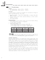 10
10
-
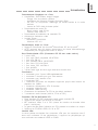 11
11
-
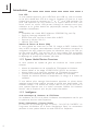 12
12
-
 13
13
-
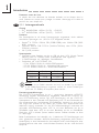 14
14
-
 15
15
-
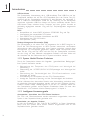 16
16
-
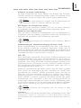 17
17
-
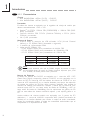 18
18
-
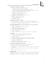 19
19
-
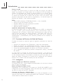 20
20
-
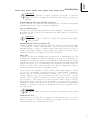 21
21
-
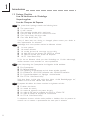 22
22
-
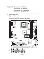 23
23
-
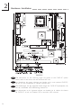 24
24
-
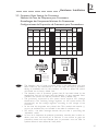 25
25
-
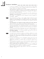 26
26
-
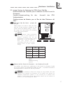 27
27
-
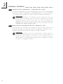 28
28
-
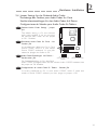 29
29
-
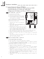 30
30
-
 31
31
-
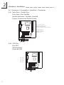 32
32
-
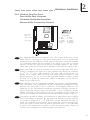 33
33
-
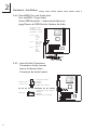 34
34
-
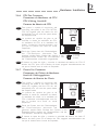 35
35
-
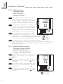 36
36
-
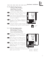 37
37
-
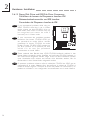 38
38
-
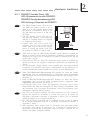 39
39
-
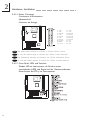 40
40
-
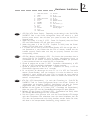 41
41
-
 42
42
-
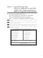 43
43
-
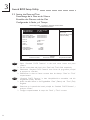 44
44
-
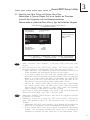 45
45
-
 46
46
-
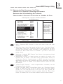 47
47
-
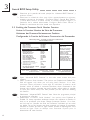 48
48
-
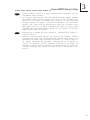 49
49
-
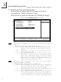 50
50
-
 51
51
-
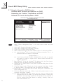 52
52
-
 53
53
-
 54
54
-
 55
55
-
 56
56
-
 57
57
-
 58
58
-
 59
59
-
 60
60
-
 61
61
-
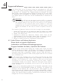 62
62
-
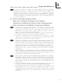 63
63
-
 64
64


VIA Technologies CM35-SC Manual de usuario
- Categoría
- Placas base
- Tipo
- Manual de usuario
- Este manual también es adecuado para
en otros idiomas
- français: VIA Technologies CM35-SC Manuel utilisateur
- English: VIA Technologies CM35-SC User manual
- Deutsch: VIA Technologies CM35-SC Benutzerhandbuch
Otros documentos
-
DFI CM33-TL Manual de usuario
-
-
Rev-A-Shelf CW35-AC Manual de usuario
-
-
HP dvd600 DVD Writer series Guía de inicio rápido
-
-
Gigabyte GO-D1600A El manual del propietario
-
-
-
Intel D815EEA Manual de usuario