Yamaha MOX6 Manual de usuario
- Categoría
- Software
- Tipo
- Manual de usuario
Este manual también es adecuado para

Contents
Using the MOX6/MOX8 Manuals..................................2
Basic Structure 3
Functional Blocks.........................................................3
Tone Generator Block ..................................................4
A/D Input Block ............................................................. 8
Sequencer Block...........................................................9
Arpeggio Block ...........................................................11
Controller Block.......................................................... 17
Effect Block .................................................................18
Internal Memory ..........................................................22
Reference 24
Voice Mode..................................................................25
Supplementary Information ............................................ 53
Voice Category List ..................................................................53
Setting examples of the Destination.........................................53
Functions of Knobs 1 – 8..........................................................54
Performance Mode .....................................................55
Supplementary Information ............................................ 74
Performance Category List ......................................................74
Functions of Knobs 1 – 8..........................................................74
Song Mode ..................................................................76
Supplementary Information ............................................ 97
Song Playback Types ..............................................................97
Song Track Loop – setting example.........................................99
Punch In/Out (Type = punch).................................................100
Basic Procedure in the Song Job Mode ................................100
Pattern Mode .............................................................101
Supplementary Information .......................................... 112
Pattern Playback Types .........................................................112
Loop Recording (Pattern).......................................................113
Mixing Mode .............................................................. 114
Supplementary Information .......................................... 124
Editing a Performance by using the Knobs............................124
Creating an Arpeggio.............................................................125
Storing the Mixing settings as a Mixing Template..................126
Master Mode.............................................................. 128
Remote Mode ............................................................ 133
Utility Mode ............................................................... 141
Quick Setup............................................................... 151
File Mode ................................................................... 153
Supplementary Information ..........................................158
File/Folder selection............................................................... 158
Playing back a SMF (Standard MIDI file) from
USB flash memory ................................................................. 158
Formatting a USB flash memory device ................................ 159
Appendix 160
About MIDI................................................................. 160
Yamaha Corp. reserves the right to update or modify this manual at any time without prior notice. The most up-to-date version is
freely available for download from the following web page.
http://www.yamaha.co.jp/manual/
Reference Manual

MOX6/MOX8 Reference Manual
2
Using the MOX6/MOX8 Manuals
Your MOX6/MOX8 synthesizer comes with four different reference guides — the Owner’s Manual, the Reference Manual (this document), the
Synthesizer Parameter Manual, and the Data List. While the Owner’s Manual is packaged together with the synthesizer as a hardcopy booklet,
this Reference Manual, Synthesizer Parameter Manual, and the Data List are provided as PDF documents on the bundled CD-ROM.
Owner’s Manual (hardcopy booklet)
Describes how to set up your MOX6/MOX8 and how to perform basic operations.
This manual explains the following operations.
• Playing in the Voice mode
• Creating a new Performance by using your favorite Voice (Performance Creator)
• Playing in the Performance mode
• Using a microphone and sounds from other audio devices
• Creating an original Song
• Making your own Patterns
• Connecting to a computer
• Using as a master keyboard (Master mode)
• Making global system settings (Utility mode)
• Saving/loading data (File mode)
Reference Manual (this PDF document)
Describes the internal design of your MOX6/MOX8 and the various parameters that can be adjusted and set.
Synthesizer Parameter Manual (PDF document)
Explains the voice parameters, effect types, effect parameters, and MIDI messages that are used for synthesizers incorporating
the Yamaha AWM2 sound generators. Read the Owner’s Manual and Reference Manual first and then use this parameter
manual, if necessary, to learn more about parameters and terms that relate to Yamaha synthesizers.
Data List (PDF document)
Provides lists such as the Waveform List, Performance List, Effect Type List, Arpeggio Type List, as well as reference materials
such as the MIDI Implementation Chart and Remote Control Function List.
Using the Reference Manual
• Using the mode tabs along the upper part of each page from the
Reference section, you can jump to the page for parameter
explanations of the corresponding mode. The list indicated at the
right of each page in the selected mode is equivalent to the
function tree. By clicking the desired item from this list, you can
jump to the page for the corresponding function’s explanations.
• You can click on any page number from the Table of Contents or
within descriptive text to jump to the corresponding page.
• You can also click on desired items and topics you want to refer to
in the “Bookmarks” index to the left of the main window, and jump to
the corresponding page. (Click the “Bookmarks” tab to open the
index if it is not displayed.)
• If you want to find information on a specific topic, function or
feature, select “Find” or “Search” from the Adobe Reader “Edit”
menu and enter a key word to locate the related information
anywhere in the document.
NOTE
The most-recent version of Adobe
®
Reader
®
can be downloaded from
the following web page.
http://www.adobe.com/products/reader/
NOTE The names and positions of menu items may vary according to the version of Adobe Reader being used.
Information
• The illustrations and LCD screens as shown in this Reference Manual are for instructional purposes only, and may appear somewhat different
from those on your instrument.
• All other trademarks are the property of their respective holders.
PERF SONG PATTERN MIX MASTER REMOTE UTILITY
QUICK SET
FILEVOICE
Voice Mode
Voice Play
[F1] PLAY
[F3] PORTA
[F4] EG
[F5] ARP ED
[F6] EFFECT
Arpeggio Edit
[F2] TYPE
[F3] MAIN
[F4] LIMIT
[F5] PLAY FX
Normal Voice Edit
Common Edit
[F1] GENERAL
[F2] OUTPUT
[F3] EQ
[F4] CTL SET
[F5] LFO
[F6] EFFECT
Element Edit
[F1] OSC
[F2] PITCH
[F3] FILTER
[F4] AMP
[F5] LFO
[F6] EQ
Drum Voice Edit
Common Edit
[F1] GENERAL
[F2] OUTPUT
[F3] EQ
[F4] CTL SET
[F6] EFFECT
Key Edit
[F1] OSC
[F2] PITCH
[F3] FILTER
[F4] AMP
[F6] EQ
Voice Job
[F1] INIT
[F2] RECALL
[F3] COPY
Voice Mode
The Voice mode is used for selecting, playing, and editing desired Voices. This section explains each parameter in the
four types (Voice Play, Normal Voice Edit, Drum Voice Edit, and Voice Job). Note that available parameters for editing
differ depending on the Voice types (Normal Voice and Drum Voice).
Voice Play
The Voice Play mode is the main “portal” by which you enter the Voice mode, and it is here where you select and play a
Voice. Some of the Voice settings can also be edited in this mode.
Voice Play display
Voic e Ban k
Voic e Num b er
Indicates the currently selected Voice bank and Voice number.
Favorite Category indicator
When assigning the currently selected Voice to the Favorite category, this indicator will appear.
Category
Indicates the Main category and Sub category of the currently selected Voice.
(ArpeggioTempo)
Indicates the arpeggio tempo set for the currently selected Voice.
NOTE
This parameter can be set also by holding the [SHIFT] button and pressing the [ENTER] button several times repeatedly at the
desired tempo. This function is referred to as “Tap Tempo.”
OCT (Octave)
Indicates the Keyboard Octave setting.
[SF1] ARP1 (Arpeggio 1) – [SF6] ARP6 (Arpeggio 6)
The Arpeggio types are assigned to the buttons with 8th note icons on the display tab. You can call them up by pressing
these buttons any time during your keyboard performance. The Arpeggio Type can be set in the Arpeggio Edit display
(page 27).
Operation
Press the [VOICE] button.
[F1] PLAY
Select the mode Select the function

MOX6/MOX8 Reference Manual
3
Basic Structure
Functional blocks
Tone Generator block
A/D Input block
Sequencer block
Arpeggio block
Controller block
Effect block
Internal memory
Reference
Voice mo de
Performance mode
Song mode
Pattern mode
Mixing mode
Master mode
Remote mode
Utility mode
Quick setup
File mode
Appendix
MIDI
Basic Structure
Functional Blocks
The MOX6/MOX8 system consists of six main functional blocks: Tone Generator, A/D Input, Sequencer, Arpeggio,
Controller, and Effect.
*1 Depending on the settings for the audio signal connections, the signals input via the A/D INPUT [L]/[R] jacks may not be sent to the system effect or master
effect.
*2 The audio signals input via the USB [TO HOST] terminal are output to the OUTPUT [L/MONO]/[R] jacks directly, bypassing the A/D Input block and Effect
block.
AWM2 (Advanced Wave Memory 2)
This instrument is equipped with a AWM2 tone generator block. AWM2 (Advanced Wave Memory 2) is a synthesis
system based on sampled waves (sound material), and is used in many Yamaha synthesizers. For extra realism,
each AWM2 Voice uses multiple samples of a real instrument’s waveform. Furthermore, a wide variety of
parameters—envelope generator, filter, modulation, and others—can be applied.
*1
*2
USB [TO HOST]
MIDI [OUT]
USB [TO HOST]
MIDI [IN]
USB [TO HOST]
A/D INPUT [L]/[R]
USB [TO HOST]
OUTPUT [L/MONO]/[R]
Controller Section
(page 17)
Keyboard
Controllers
Tone Generator
(page 4)
AWM2 Tone Generator
16 Parts
Voices and Performances
Arpeggio Block (page 11)
Arpeggio Playback x 4
Preset Arpeggio
User Arpeggio
Sequencer Block
(page 9)
16-Track MIDI Sequencer
Songs and Patterns
Effects (page 18)
System Effect
Insertion Effect x 3
Element EQ
Part EQ x 16
Master Effect
Master EQ
A/D Input (page 8)
Song Mixing
Pattern Mixing
MIDI Message Flow
Audio Signal Flow
Computer External MIDI equipment
Computer
Microphone, guitar,
audio equipment,
etc.
Computer
Powered
speakers,
etc.
MIDI OUT MIDI IN AUDIO IN AUDIO OUT

MOX6/MOX8 Reference Manual
4
Basic Structure
Functional blocks
Tone Generator block
A/D Input block
Sequencer block
Arpeggio block
Controller block
Effect block
Internal memory
Reference
Voice mo de
Performance mode
Song mode
Pattern mode
Mixing mode
Master mode
Remote mode
Utility mode
Quick setup
File mode
Appendix
MIDI
Tone Generator Block
The tone generator block is what actually produces sound in response to the MIDI messages received from the
Sequencer block, Controller block, Arpeggio block and from the external MIDI instrument via the MIDI [IN] terminal or
the USB [TO HOST] terminal. The MIDI messages are assigned to sixteen independent channels, and the instrument is
capable of simultaneously playing sixteen separate Parts, via the sixteen MIDI channels. However, the sixteen-channel
limit can be overcome by using separate MIDI “ports,” each supporting sixteen channels. The tone generator block of
this instrument can handle MIDI messages over Port 1. The structure of the tone generator block differs depending on
the mode.
Tone Generator block in the Voice Mode
Only one MIDI channel can be recognized in the Voice mode because only one part is available in this
mode. This status is referred to as a “single timbre” tone generator. A Voice is played from the keyboard,
using a single part. To set the MIDI receive channel for single timbre operation (Voice and Performance
modes), use the “BasicRcvCh” parameter (page 148) in the Utility MIDI display. In the Voice mode, the
instrument recognizes only data over MIDI Port 1.
NOTE
If you want to play Song data on an external MIDI sequencer or computer consisting of multiple MIDI
channels, make sure to use the Song/Pattern mode (page 76).
A program that contains the sonic elements for generating a specific musical instrument sound is
referred to as a “Voice.” Internally, there are two Voice types: Normal Voices and Drum Voices. Normal
Voices are mainly pitched musical instrument type sounds that can be played over the range of the
keyboard. Each Voice consists of up to eight Elements (Normal Voice) or up to 73 keys (Drum Voice). An
Element or Drum Key is the basic and the smallest unit for a Voice. This means that only one Element or
key can produce a musical instrument sound. In addition, a Normal Voice can produce even more
realistic sound or various types of sound by combining multiple Elements. Each Voice is created by
editing parameters unique to each Element/Key (Element Edit parameters/Key Edit parameters) and
parameters common to all the Elements/Keys (Common Edit parameters).
NOTE
For instructions on editing a Normal Voice, see page 30. For instructions on editing a Drum Voice, see page
47.
Normal Voices
This is a Voice which is played conventionally from
the keyboard, with standard pitches sounding for
each key. A Normal Voice consists of up to eight
Elements. Depending on the settings in the Voice
Edit mode, these Elements are sounded
simultaneously, or different Elements are sounded
according to the note range, velocity range and
the XA (Expanded Articulation) settings. The illustration is an example of a Normal Voice. Since the six
Elements here are distributed across both the note range of the keyboard and the velocity range, a
different Element sounds depending on which note you play and how strongly you play it. In the velocity
distribution, Elements 1, 3 and 5 sound when playing the keyboard softly, while Elements 2, 4 and 6
sound when playing it strongly. In the note distribution, Elements 1 and 2 sound in the lower range of the
keyboard, Elements 3 and 4 sound in the middle range, and Elements 5 and 6 sound in the higher
range. In the velocity distribution, Elements 1, 3 and 5 sound when playing the keyboard softly, while
Elements 2, 4 and 6 sound when playing it strongly. In a practical example of this in use, a piano Voice
could be composed of six different samples. Elements 1, 3 and 5 would be the sounds of the piano
played softly, over the respective note ranges, while Elements 2, 4 and 6 would be strongly played
sounds, for each respective note range. Actually, the MOX6/MOX8 is even more flexible than this, since
it allows up to eight independent Elements.
Part structure in the Voice mode
Voice
Normal Voices and Drum Voices
Velocit y
Element 2
Element 1
Element 4
Element 3
Element 6
Element 5

MOX6/MOX8 Reference Manual
5
Basic Structure
Functional blocks
Tone Generator block
A/D Input block
Sequencer block
Arpeggio block
Controller block
Effect block
Internal memory
Reference
Voice mo de
Performance mode
Song mode
Pattern mode
Mixing mode
Master mode
Remote mode
Utility mode
Quick setup
File mode
Appendix
MIDI
Drum Voices
Drum Voices are mainly percussion/drum sounds that are assigned to individual notes on the keyboard.
Unlike Elements, a Drum key is equivalent to the corresponding note, meaning that you cannot change
its range. Drum or percussion sounds are assigned to each Drum Key. You can create various types of
Drum Voices by changing the drum or percussion sound assigned to each key and edit the parameters
such as pitch and EG.
Expanded Articulation (XA) is a specially designed tone generation system of the MOTIF XS that
provides greater performance flexibility and acoustic realism. This feature, adopted from the MOTIF XS
synthesizer, allows you to more effectively recreate realistic sound and natural performance
techniques—such as legato and staccato—and provides other unique modes for random and alternate
sound changes as you play.
Realistic legato performance
Conventional synthesizers recreate a legato effect in the mono mode by continuing the volume
envelope of a previous note on to the next one. However, this results in an unnatural sound different from
that of an actual acoustic instrument. The MOX6/MOX8 more accurately reproduces a legato effect by
allowing specific Elements to be sounded when playing legato and other Elements to be played
normally (with the XA Control parameter settings “normal” and “legato”).
Authentic note release sound
Conventional synthesizers cannot adequately produce the sounds of notes on acoustic instruments
being released. The MOX6/MOX8 reproduces these special, characteristic sounds by setting the XA
Control parameter of certain Elements to “keyOffSound.”
Subtle sound variations for each note played
Conventional synthesizers attempt to reproduce this by randomly changing the pitch and/or filter.
However, this produces an electronic effect and is different from the real sound changes on an acoustic
instrument. The MOX6/MOX8 more accurately reproduces these subtle sound variations by using the
XA Control parameter settings “waveCycle” and “waveRandom.”
Switching among different sounds to recreate the natural performance on an
acoustic instrument
Acoustic instruments have their own unique characteristics—even specific, unique sounds that are
produced only at certain times in a performance. These include the flutter tonguing on a flute or the
playing of high harmonics on an acoustic guitar. Conventional synthesizers (before the MOTIF XS
series) could realize such sounds, for example, by triggering them through high (strong) velocity. The
MOX6/MOX8 recreates these by allowing you to switch between the sounds while you play—using the
ASSIGNABLE FUNCTION [1]/[2] buttons and the XA Control parameter settings, “AF1 On,” “AF2 On”
and “all AF off.”
NOTE
You can turn the ASSIGNABLE FUNCTION [1]/[2] button on or off also by transmitting the Control Change
number specified as “AF1”/”AF2” (page 146) in the Utility CTL ASN display from an external device.
New sounds and new styles of playing
The highly versatile functions above can be applied effectively not only to acoustic sounds but also to
synthesizer and electronic Voices as well. The XA feature opens up enormous potential for realizing
authentic sounds, performing expressively and coming up with creative new styles of playing.
Expanded Articulation (XA)
C0
C1 C6
Individual drum sounds
(different for each key)

MOX6/MOX8 Reference Manual
6
Basic Structure
Functional blocks
Tone Generator block
A/D Input block
Sequencer block
Arpeggio block
Controller block
Effect block
Internal memory
Reference
Voice mo de
Performance mode
Song mode
Pattern mode
Mixing mode
Master mode
Remote mode
Utility mode
Quick setup
File mode
Appendix
MIDI
Elements and Drum Keys are the smallest “building blocks” in the MOX6/MOX8 that comprise a Voice;
in fact, only one Element or one Drum Key could be used to create a Voice. These small sound units can
be built, enhanced and processed by a variety of traditional synthesizer parameters, such as Oscillator,
Pitch, Filter, Amplitude, and LFO (shown below).
Oscillator
This unit outputs the wave which determines the basic pitch. You can assign the waveform (or basic
sound material) to each Element of a Normal Voice or each Key of a Drum Voice. In the case of a Normal
Voice, you can set the note range for the Element (the range of notes on the keyboard over which the
Element will sound) as well as the velocity response (the range of note velocities within which the
Element will sound). In addition, the XA related parameters of this unit can be set. Each waveform
consists of sample(s) created by recording the sound of the actual instrument and assigning
appropriate keyboard and velocity settings. Oscillator related parameters can be set in the Oscillator
display (pages 38 and 48).
Pitch
This unit controls the pitch of the sound (wave) output from the Oscillator. In the case of a Normal Voice,
you can detune separate Elements, apply Pitch Scaling and so on. Also, by setting the PEG (Pitch
Envelope Generator), you can control how the pitch changes over time. Pitch related parameters can be
set in the PITCH display (page 39) of the Voice Element Edit. Note that the Pitch related parameters of a
Drum Voice can be set in the PITCH display (page 49) of Drum Voice Key Edit.
Filter
This unit modifies the tone of the sound output from Pitch by cutting the output of a specific frequency
portion of the sound. Also, by setting the FEG (Filter Envelope Generator), you can control how the
Cutoff Frequency of the Filter changes over time. Filter related parameters can be set in the FILTER
display (pages 41 and 50) of Voice Element Edit or Drum Voice Key Edit.
Amplitude
This unit controls the output level (amplitude) of the sound output from the Filter block. The signals are
then sent at this level to the Effect block. Also, by setting the AEG (Amplitude Envelope Generator), you
can control how the volume changes over time. Amplitude related parameters can be set in the AMP
display (pages 43 and 50) of Voice Element Edit or Drum Voice Key Edit.
LFO (Low Frequency Oscillator)
As its name suggests, the LFO produces a wave of a low frequency. These waves can be used to vary
the pitch, filter or amplitude of each Element to create effects such as vibrato, wah and tremolo. LFO
can be set independently for each Element; it can also be set globally for all Elements. LFO related
parameters can be set in the LFO display (pages 33 and 45) of Voice Common Edit or Voice Element
Edit.
Elements and Drum Keys
OSC
(Oscillator)
LFO
Low Frequency
Oscillator
PITCH
Controls the pitch
of the sound.
FILTER
Changes the tonal
quality of the sound
output from the
PITCH unit.
Waveform
(AWM2)
AMP
Controls the output level
(amplitude) of the sound
output from the FILTER
unit. The signals are then
sent at this level to the
Effect block.
Pitch EG
(Pitch Envelope
Generator)
Filter EG
(Filter Envelope
Generator)
Amplitude EG
(Amplitude Envelope
Generator)

MOX6/MOX8 Reference Manual
7
Basic Structure
Functional blocks
Tone Generator block
A/D Input block
Sequencer block
Arpeggio block
Controller block
Effect block
Internal memory
Reference
Voice mo de
Performance mode
Song mode
Pattern mode
Mixing mode
Master mode
Remote mode
Utility mode
Quick setup
File mode
Appendix
MIDI
Normal Voices
Preset Banks 1 – 8 1024 Normal Voices (128 Voices for each Bank)
User Banks 1 – 3 384 Voices (128 Voices for each Bank)
GM Bank 128 Voices
Drum Voices
Preset Drum Bank 64 Voices
User Drum Bank 32 Voices
GM Drum Bank 1 Voice
Tone Generator block in the Performance mode
In this mode, the tone generator block receives MIDI data over a single channel. This status is referred
to as a “single timbre” tone generator. This mode lets you play a Performance (in which multiple Voices
or Parts are combined—in a layer, or in other configurations) using the keyboard. Keep in mind that
Song data on an external sequencer consisting of multiple MIDI channels will not play back properly in
this mode. If you are using an external MIDI sequencer or computer to play the instrument, make sure to
use the Song mode or Pattern mode.
A program in which multiple Voices (Parts) are combined in a layer, or in other configurations is referred
to as a “Performance.” Each Performance can contain up to four different Parts (Voices). Each
Performance can be created by editing parameters unique to each Part and parameters common to all
Parts in Performance mode (page 55).
Two User Banks are provided. Each Bank contains 128 Performances, for a total of 256 User
Performances.
Tone Generator block in the Song mode/Pattern mode
In these modes, multiple Parts are provided and different Voices and different melodies or phrases can
be played back for each Part. A MIDI tone generator that simultaneously receives over multiple MIDI
channels and plays multiple instrument Parts is referred to as a “multi-timbral” tone generator. The
settings for the multi-timbral tone generator are collectively referred to as a “Mixing.” You can use the
Mixing when playing the MOX6/MOX8 sounds by using an external MIDI sequencer as well as using the
sequencer block of the instrument. In this case, you should use the Mixing of the Song or Pattern that
does not contain any sequence data.
A program in which multiple Voices are assigned to Parts for multi-timbral play in the Song and Pattern
modes is referred to as a “Mixing.” Each Mixing can contain up to 16 parts. Each Mixing can be created
by editing parameters unique to each Part and parameters common to all Parts in the Mixing mode
(page 114).
Also, one Mixing has up to sixteen memory locations for saving Normal Voices. These Voices which are
saved are called Mixing Voices. Normally, the Voice stored in the Voice mode is assigned to each
Memory structure of Voices
Part structure in the Performance mode
Performance
Performance Memory contents
Part structure of the tone generator block in the Song mode/Pattern
mode
About Mixing

MOX6/MOX8 Reference Manual
8
Basic Structure
Functional blocks
Tone Generator block
A/D Input block
Sequencer block
Arpeggio block
Controller block
Effect block
Internal memory
Reference
Voice mo de
Performance mode
Song mode
Pattern mode
Mixing mode
Master mode
Remote mode
Utility mode
Quick setup
File mode
Appendix
MIDI
Mixing Part. In this case, the sound of the Song/Pattern you created may change unexpectedly if you
edit or delete the Voice used for the Song/Pattern Mixing in the Voice mode. Mixing Voices are provided
to prevent these accidental sound changes.
A Mixing program is provided for each Song or Pattern. Selecting a different Song/Pattern calls up a
different Mixing program. A Mixing Voice provides 16 memories for each Mixing program (Song or
Pattern). Selecting a different Song/Pattern calls up the different Mixing Voice as well as the Mixing
program. If you wish to use a Mixing Voice of a certain Song/Pattern for another Song/Pattern, execute
the Copy operation (page 123) in the Mixing Voice Job. Note that up to 256 Mixing Voices can be stored
for all Songs and Patterns. If the memory for Mixing Voices is full, delete the Mixing Voices you don’t
need by executing the Delete job of the Mixing Voice job.
A/D Input Block
This block handles the audio signal input from the A/D INPUT [L]/[R] jacks. Various parameters such as volume, pan,
and effect can be set for the audio signal and the sound is output together with other Voices. The Insertion Effect as well
as the System Effects can be applied to the audio signal input via the A/D INPUT [L]/[R] jacks. The A/D Input block
related parameters can be set in the following display.
The effect which is applied to the audio signal input from the A/D INPUT [L]/[R] jacks is set in the USB I/O display (page
147) of the Utility mode. The gain of the audio signal from the A/D INPUT [L]/[R] jacks can be adjusted via the A/D
INPUT [GAIN] knob on the panel. Moreover, the on/off setting of the audio signal from the A/D INPUT [L]/[R] jacks can
be set via the A/D INPUT [ON/OFF] button.
Memory structure of Mixing
Maximum Polyphony
Maximum polyphony refers to the highest number of notes that can be sounded simultaneously
from the internal tone generator of the instrument. The maximum polyphony of this synthesizer is
64. When the internal tone generator block receives a number of notes exceeding the maximum
polyphony, previously played notes are cut off. Keep in mind this may be especially noticeable
with Voices not having decay. Furthermore, the maximum polyphony applies to the number of
Voice Elements used, not the number of Voices. When Normal Voices that include up to eight
Elements are used, the maximum number of simultaneous notes may be less than 64.
Mode Display
Corresponding page in
the Reference Manual
Voice mode VCE A/D display in the Utility mode Page 145
Performance mode A/D IN display in Performance Common Edit Page 62
Song/Pattern mode A/D IN display in Mixing Common Edit Page 116

MOX6/MOX8 Reference Manual
9
Basic Structure
Functional blocks
Tone Generator block
A/D Input block
Sequencer block
Arpeggio block
Controller block
Effect block
Internal memory
Reference
Voice mo de
Performance mode
Song mode
Pattern mode
Mixing mode
Master mode
Remote mode
Utility mode
Quick setup
File mode
Appendix
MIDI
Sequencer Block
This lets you create Songs and Patterns by recording and editing your performances as MIDI data (from the controller
block), allowing you to play the data back with the tone generator block.
Sequencer block in the Song mode
A Song is created by recording your keyboard performance as MIDI sequence data to individual
Tracks. A Song on this synthesizer is effectively the same as a Song on a MIDI sequencer, and playback
automatically stops at the end of the recorded data.
A Song consists of 16 separate Tracks, a Scene Track, and a Tempo Track. You can record these Tracks
by using Realtime recording or Step recording (page 79). Moreover, you can insert or edit the recorded
data using Song Edit (page 84).
Sequence Tracks 1 – 16
Lets you record MIDI data.
Scene Track
Lets you record Scene change settings, such as Track mute and solo. These can be set in the Song
Play display (page 76) and recalled during Song playback. During Song playback, the Track mute and
solo settings change automatically according to the settings you’ve recorded to the Scene Track.
Tempo Track
Lets you record Tempo change settings. During Song playback, the Tempo changes automatically
according to the settings you’ve recorded to this Track.
This function allows Songs to be “chained” together for automatic sequential playback. You can set the
playback order in Song Play (page 76).
Sequencer block in the Pattern mode
In the MOX6/MOX8, the term “Pattern” refers to a relatively short musical or rhythmic Phrase—1 to 256
measures—which is used for looped playback. Therefore, once Pattern playback starts, it continues
until you press the [ ] (Stop) button.
Patterns are more than just a single Phrase—they include 16 variations called “Sections.” These
Sections can be changed during playback and used as rhythmic/backing variations for the various
parts of a Song. For example, you could use one Section for the verse, another for the chorus, and a
third for the bridge. The Pattern related settings such as tempo and Mixing do not change even when
the Section is switched, keeping the overall playback consistent in feel and rhythm through the
changes. You can use the Section function as a convenient compositional tool, instantly creating the
backing Pattern variations for a Song, such as melody A, melody B, and main theme. For instructions on
changing Patterns and Sections, see the MOX6/MOX8 Owner’s Manual.
About Songs
Song Track structure
Song Chain
About Patterns
Section
Song 01 Song 22 Song 15

MOX6/MOX8 Reference Manual
10
Basic Structure
Functional blocks
Tone Generator block
A/D Input block
Sequencer block
Arpeggio block
Controller block
Effect block
Internal memory
Reference
Voice mo de
Performance mode
Song mode
Pattern mode
Mixing mode
Master mode
Remote mode
Utility mode
Quick setup
File mode
Appendix
MIDI
Pattern Chain allows you to string several different Sections (within a single Pattern) together to make a
single, complete Song. You can have the MOX6/MOX8 automatically change Sections by creating a
Pattern Chain beforehand, recording Pattern playback with Section changes from the Pattern Chain
display. One Pattern Chain can be created for each Pattern in the Pattern Chain display (page 103). You
can also use this feature when creating Songs based on a certain Pattern, since the created Pattern
Chain can be converted into a Song in Pattern Chain Edit (page 104).
This is the basic MIDI sequence data in a Track—and the smallest unit—used in creating a Pattern.
“Phrases” are short musical/rhythmic passages for a single instrument, such as a rhythm pattern for the
rhythm part, a bass line for the bass part, or a chord backing for the guitar part. This synthesizer
features memory space for 256 of your own original User Phrases.
NOTE
The MOX6/MOX8 provides no Preset Phrases.
A Pattern consists of 16 separate Tracks. See “Sequence Tracks 1 – 16” of “Song Track Structure.”
(Page 9)
A Pattern consists of 16 Tracks to which the Phrase can be assigned. MIDI data cannot be directly
recorded to each Track in the Pattern mode. Recording is done to an empty User Phrase. The newly
created Phrase is automatically assigned to the recording Track.
Sequencer block applied to both Songs and Patterns
MIDI Tracks are created by recording your keyboard performance in the Song Record mode/Pattern
Record mode. MIDI sequence data is recorded to the MIDI Track and the Normal Voice or Drum Voice is
assigned to the Mixing part corresponding to the Track. To edit the Mixing parameters such as Voice,
volume and pan for each Track, press the [MIXING] button to enter the Mixing mode (page 114), then
edit them for the Mixing Part corresponding to the desired Track. Note that Track 1 does not always
correspond to Mixing Part 1. As illustrated below, each Track of the Song sequence data and each
Mixing Part of the tone generator block are connected when the output channel (TxCH) equals the
receive channel (RcvCH). In other words, the sequence data of each Track plays the corresponding
Parts (those having the same MIDI channel assignment) in the tone generator block. The Transmit
Channels of each Track can be set in the TRACK display (page 78) of the Song mode or Pattern mode
while the Receive Channels of each Part can be set in the VOICE display (page 117) of Mixing Edit.
Pattern Chain
Phrase
Pattern Track Structure
Pattern Tracks and Phrases
MIDI Tracks and Mixing settings
Section A Section B Section C
Track 1
Track 2
:
Track 16
Phrase 001
Phrase 002
:
Phrase 003
Phrase 001
Phrase 002
Phrase 003
:
MIDI data
MIDI data
MIDI data
:

MOX6/MOX8 Reference Manual
11
Basic Structure
Functional blocks
Tone Generator block
A/D Input block
Sequencer block
Arpeggio block
Controller block
Effect block
Internal memory
Reference
Voice mo de
Performance mode
Song mode
Pattern mode
Mixing mode
Master mode
Remote mode
Utility mode
Quick setup
File mode
Appendix
MIDI
NOTE When you play the keyboard in the Mixing mode, the selected Part will not sound, but the Part assigned to the
same numbered Track as the selected part will sound, For example, when setting as in the above illustration,
playing the keyboard sounds Part 1 even if Part 2 is selected in the Mixing mode.
Sequencer block applied to the Performance mode
You can record your keyboard performance in the Performance mode to the Song or Pattern. You can
record knob operations, controller operations and Arpeggio playback as well as your keyboard playing
to the specified Track as MIDI events.
NOTE
In Performance recording, operating the knobs only result in the Control Change messages being recorded;
Parameter Change messages cannot be recorded. For details regarding Control Change messages, see the
“Synthesizer Parameter Manual” PDF document.
Arpeggio playback data for Parts 1 – 4 of the Performance will be recorded to the specified four Tracks
(in the REC TR display of Performance Record) of the Song/Pattern respectively. Your keyboard
performance and controller/knob operations (common to Parts 1 – 4) will be recorded to Tracks 1 – 4
separately.
NOTE
For details on operation, refer to the MOX6/MOX8 Owner’s Manual.
Arpeggio Block
This block lets you automatically trigger musical and rhythmic phrases using the current Voice by simply pressing a
note or notes on the keyboard. The Arpeggio sequence also changes in response to the actual notes or chords you
play, giving you a wide variety of inspiring musical phrases and ideas—both in composing and performing. Four
Arpeggio types can be played back at the same time even in the Song mode and Pattern mode.
Arpeggio categories
The Arpeggio types are divided into 18 categories as listed below. The categories are based on instrument type.
Category List
NOTE Categories named “GtMG” and “BaMG” include Arpeggio types appropriate for using with a Mega Voice.
Performance Recording
ApKb Acoustic Piano & Keyboard Lead Synth Lead
Organ Organ PdMe Synth Pad / Musical Effect
GtPl Guitar / Plucked CPrc Chromatic Percussion
GtMG Guitar for “Mega Voice” DrPc Drum / Percussion
Bass Bass Seq Synth Seq
BaMG Bass for “Mega Voice” Chord Chord Seq
Strng Strings Hybrd Hybrid Seq
Brass Brass Cntr Control
RdPp Reed / Pipe
Song/Pattern
Sequencer block
Sequence data
(Song, Pattern)
Track 1
Track 2
Track 3
:
Tra ck 16
Part 1
Part 2
Part 3
:
Part 16
TxCH
2
2
3
:
16
RcvCH
2
3
3
:
16
Tone generator block
Mixing
Recording

MOX6/MOX8 Reference Manual
12
Basic Structure
Functional blocks
Tone Generator block
A/D Input block
Sequencer block
Arpeggio block
Controller block
Effect block
Internal memory
Reference
Voice mo de
Performance mode
Song mode
Pattern mode
Mixing mode
Master mode
Remote mode
Utility mode
Quick setup
File mode
Appendix
MIDI
Sub categories
The Arpeggio categories are divided into the sub categories listed below. Because the sub categories are listed based
on the music genre, it is easy to find the sub category appropriate for your desired music style.
Sub Category List
NOTE Arpeggio types belonging to the Sub Categories marked with an asterisk (*) contain some velocity ranges, to
which each has a different phrase assigned. When a type of these categories is selected in the Voice mode, it
is a good idea to set the Velocity Limit of each Element to the same range as below.
Velocity ranges of each Arpeggio type.
2Z_*****: 1 – 90, 91 – 127
4Z_*****: 1 – 70, 71 – 90, 91 – 110, 111 – 127
8Z_*****: 1 – 16, 17 – 32, 33 – 48, 49 – 64, 65 – 80, 81 – 96, 97– 108, 109 – 127
PadL_*****: 1 – 1, 2 – 2, 3 – 127
PadH_*****: 1 – 112, 113 – 120, 121 – 127
Arpeggio Type Name
The Arpeggio Types are named according to certain rules and abbreviations. Once you understand these rules and
abbreviations, you’ll find it easy to browse through and select the desired Arpeggio Types.
Arpeggio type with “_ES” at the end of the type name (example: HipHop1_ES)
These Arpeggio types use the same multi Track Arpeggio architecture as the MOTIF ES. This ES type of
arpeggio has the following benefits: 1) These arpeggios can create complex notes and chords even
when triggered by one note. 2) The arpeggio closely follows the notes played on the keyboard (only in
the area where the arpeggio is assigned), allowing a good deal of harmonic freedom and the possibility
to “solo” using these arpeggios.
Arpeggio type with “_XS” at the end of the type name (example: Rock1_XS)
These Arpeggios use a newly developed chord recognition technology to determine what notes should
be played back by the Arpeggio. This XS type of arpeggio has the following benefits: 1) The arpeggios
respond only to an area on the keyboard where an XS type of arpeggio is assigned. Other areas of the
keyboard do not affect the chord recognition. This allows very natural keyboard playing across the
entire keyboard with arpeggio generated bass and backing parts. 2) The arpeggio will always play
harmonically correct parts. These are especially useful for bass and chordal backing parts.
Mega Voices and Mega Voice Arpeggios
Normal Voices use velocity switching to make the sound quality and/or level of a Voice change according to how
strongly or softly you play the keyboard—giving greater authenticity and natural response to these Voices.
However Mega Voices have a very complex structure with many different layers that is not suitable for playing
manually. Mega Voices were developed specifically to be played by Mega Voice arpeggios to produce
incredibly realistic results. You should always use Mega Voices with Mega Voice Arpeggios (included in “GtMG”
and “BaMG” category). For details regarding the Mega Voice Arpeggios, see the “Voice Type” of the “Arpeggio
Type List” in the “Data List” PDF document.
Rock Rock Z.Pad Zone Velocity for Pad*
R&B R&B Filtr Filter
Elect Electronic Exprs Expression
Jazz Jazz Pan Pan
World World Mod Modulation
Genrl General Pbend Pitch Bend
Comb Combination Asign Assign 1/2
Zone Zone Velocity*

MOX6/MOX8 Reference Manual
13
Basic Structure
Functional blocks
Tone Generator block
A/D Input block
Sequencer block
Arpeggio block
Controller block
Effect block
Internal memory
Reference
Voice mo de
Performance mode
Song mode
Pattern mode
Mixing mode
Master mode
Remote mode
Utility mode
Quick setup
File mode
Appendix
MIDI
Arpeggio type with a normal name (example: UpOct1)
In addition to the above types, there are three playback types: the Arpeggios created for use of Normal
Voices and played back using only the played notes and their octave notes (page 15), the Arpeggios
created for use of Drum Voices (page 16), and Arpeggios containing mainly non-note events (page 16).
How to use the Arpeggio Type List
The Arpeggio Type list in the “Data List” PDF document contains the following columns.
NOTE Note that this list is for illustration purposes only. For a complete listing of the Arpeggio Types, see the “Data List” PDF
document.
Main Category
Indicates an Arpeggio Main Category.
Sub Category
Indicates an Arpeggio Sub Category.
ARP No (Arpeggio Number)
Indicates the Arpeggio type number.
ARP Name (Arpeggio Name)
Indicates the Arpeggio Name.
Time Signature
Indicates the time signature or meter of the Arpeggio type.
Length
Indicates the data length (amount of measures) of the Arpeggio type. When the Loop parameter
*1
is set to “off,” the Arpeggio plays back for this length and stops.
Original Tempo
Indicates the appropriate tempo value of the Arpeggio type. Note that this tempo is not set
automatically when selecting an Arpeggio type.
Accent
The circle indicates that the Arpeggio uses the Accent Phrase feature (page 14).
Random SFX
The circle indicates that the Arpeggio uses the SFX feature (page 15).
Voice Type
Indicates the voice type appropriate for the Arpeggio Type. When the “VoiceWithARP” (Voice with
Arpeggio)
*2
is set to “on” in the Song/Pattern Record, the voice of this type is automatically
selected.
*1 The Loop parameter can be set in the PLAY FX display of Arpeggio Edit for Voice mode (page 28), Performance
mode (page 58), and Song/Pattern mode (page 83).
*2 The “VoiceWithARP” parameter can be set in the MAIN display of the Arpeggio Edit for Song/Pattern mode (page
83).
Main
Category
Sub
Category
ARP
No.
ARP Name
Time
Signature
Length
Original
Tempo
Accent
Random
SFX
Voice Type
ApKb Rock 1 70sRockB 4 / 4 2 130 Acoustic Piano
ApKb Rock 2 70sRockC 4 / 4 1 130 :
ApKb Rock 3 70sRockD 4 / 4 2 130
ApKb Rock 4 70sRockE 4 / 4 4 130
ApKb Rock 5 70sRockF 4 / 4 2 130
ApKb Rock 6 70sRockG 4 / 4 1 130
ApKb Rock 7 70sRockH 4 / 4 1 130

MOX6/MOX8 Reference Manual
14
Basic Structure
Functional blocks
Tone Generator block
A/D Input block
Sequencer block
Arpeggio block
Controller block
Effect block
Internal memory
Reference
Voice mo de
Performance mode
Song mode
Pattern mode
Mixing mode
Master mode
Remote mode
Utility mode
Quick setup
File mode
Appendix
MIDI
Arpeggio related settings
There are several methods for triggering and stopping the Arpeggio playback. In addition, you can set whether or not
SFX sounds and special Accent Phrases are triggered along with the normal sequence data. This section covers the
Arpeggio related parameters which can be set in the Voice, Performance and Mixing modes.
The following three settings are available for turning the Arpeggio playback on/off.
NOTE
For the displays including the “Hold” and “TriggerMode” parameters, see MAIN display and PLAY FX display
of the Arpeggio Edit for Voice mode (page 28), Performance mode (page 58), and Song/Pattern mode (page
83).
NOTE When receiving the MIDI sustain message (control change #64) with “Arp Sw” set to “on,” you can obtain the
same result by setting “Arp Hold” to “on.”
When the ARP lamp is turned on by pressing the Knob Function 2 button a few times, you can use
knobs 5 – 8 to control Arpeggio playback. Try this out and listen for the changes in the sound. For
details regarding the effect of the knobs 5 – 8, see “Knob Functions” of the Voice mode (page 54).
Accent Phrases are composed of sequence data included in some Arpeggio types, sounding only
when you play notes at a velocity higher (stronger) than that specified in the Accent Velocity Threshold
parameter. If it is hard to play at velocities necessary to trigger the Accent Phrase, set the “AccntVelTh”
(Accent Velocity Threshold) parameter to a lower value.
NOTE
For the displays including the “AccntVelTh” parameters, see PLAY FX display of the Arpeggio Edit for Voice
mode (page 28), Performance mode (page 58), and Song/Pattern mode (page 83).
NOTE For information on Arpeggio types that use this function, refer to the “Arpeggio Type List” in the “Data List”
PDF document.
Turning Arpeggio playback on/off
To play the Arpeggio only when the note is pressed: Set the “Hold” parameter to “off” and the “TriggerMode”
parameter to “gate.”
To continue the Arpeggio even if the note is released: Set the “Hold” parameter to “on” and the “TriggerMode”
parameter to “gate.”
To toggle the Arpeggio playback on/off whenever the
note is pressed:
Set the “TriggerMode” parameter to “toggle.” The “Hold”
parameter can be set to either “on” or “off.”
Using the knobs to control Arpeggios
Accent Phrase
Press this button a few times so that the lamp lights
Arpeggio functions controlled via the knobs

MOX6/MOX8 Reference Manual
15
Basic Structure
Functional blocks
Tone Generator block
A/D Input block
Sequencer block
Arpeggio block
Controller block
Effect block
Internal memory
Reference
Voice mo de
Performance mode
Song mode
Pattern mode
Mixing mode
Master mode
Remote mode
Utility mode
Quick setup
File mode
Appendix
MIDI
Some Arpeggio types feature a Random SFX function which will trigger special sounds (such as guitar
fret noises) when the note is released. The following parameters affecting Random SFX are provided.
NOTE
For the displays including the “RandomSFX,” “SFXVelOffset,” and “SFXKeyOnCtrl” parameters, see PLAY FX
display of the Arpeggio Edit for Voice mode (page 28), for Performance mode (page 58), for Song/Pattern
mode (page 83).
NOTE For information on Arpeggio types that use this function, refer to the “Arpeggio Type List” in the “Data List”
PDF document.
Each mode has one Arpeggio Edit display for the Arpeggio settings. If you press the ARP [EDIT] button
in any of the modes, the Arpeggio Edit display will be shown.
Arpeggio playback types
There are three main Arpeggio playback types as described below.
Arpeggio types (belonging to all categories except for DrPC and Cntr) created for use of Normal Voices
have the following three playback types.
Playback of played notes only
The Arpeggio is played back using only the played note(s) and octave notes.
Playback of a programmed sequence according to the played notes
These Arpeggio types have the several sequences each of which is suited for a certain chord type.
Even if you press only one note, the Arpeggio is played back using the programmed sequence—
meaning that notes other than the ones you play may be sounded. Pressing another note triggers a
transposed sequence using the pressed note as the new root note. Adding notes to those already held
changes the sequence accordingly. Arpeggios with this playback type have “_ES” at the end of the type
name.
Playback of a programmed sequence according to the played chord
These Arpeggio types created for use with Normal Voices are played back to match the chord type
determined by detecting the notes you play on the keyboard. Arpeggios with this playback type have
“_XS” at the end of the type name.
NOTE
When the “KeyMode” parameter is set to “sort” or “sortdirect,” the same sequence is played back no matter
what order you play the notes. When the “KeyMode” parameter is set to “thru” or “thrudirect,” a different
sequence is played back depending on the order you play the notes.
NOTE Since these types are programmed for Normal Voices, using them with Drum Voices may not produce
musically appropriate results.
Random SFX
For turning the Random SFX on/off: Random SFX parameter
For setting the volume of the SFX sound: SFXVelOffset (Random SFX Velocity Offset) parameter
For determining whether or not the volume of the SFX
sound is controlled by velocity:
SFXKeyOnCtrl (Random SFX Key on Control) parameter
Arpeggio setting displays
Arpeggios for Normal Voices

MOX6/MOX8 Reference Manual
16
Basic Structure
Functional blocks
Tone Generator block
A/D Input block
Sequencer block
Arpeggio block
Controller block
Effect block
Internal memory
Reference
Voice mo de
Performance mode
Song mode
Pattern mode
Mixing mode
Master mode
Remote mode
Utility mode
Quick setup
File mode
Appendix
MIDI
These Arpeggio types are programmed specifically for use with Drum Voices, giving you instant access
to various rhythm patterns. Three different playback types are available.
Playback of a drum pattern
Pressing any note(s) will trigger the same rhythm pattern.
Playback of a drum pattern, plus additional played notes (assigned drum
instruments)
Pressing any note will trigger the same rhythm pattern. Adding notes to the one already held produces
additional sounds (assigned drum instruments) for the drum pattern.
Playback only of the played notes (assigned drum instruments)
Playing a note or notes will trigger a rhythm pattern using only the notes played (assigned drum
instruments). Keep in mind that even if you play the same notes, the triggered rhythm pattern differs
depending on the order of the notes played. This gives you access to different rhythm patterns using
the same instruments simply by changing the order in which you play the notes, when the “KeyMode”
parameter is set to “thru” or “thrudirect.”
NOTE
The three playback types above are not distinguished by category name or type name. You'll have to actually
play the types and hear the difference.
NOTE Since these types are programmed for Drum Voices, using them with Normal Voices may not produce
musically appropriate results.
These arpeggio types are programmed primarily with Control Change and Pitch Bend data. They are
used to change the tone or pitch of the sound, rather than play specific notes. In fact, some types
contain no note data at all. When using a type of this category, set the “KeyMode” parameter to “direct,”
“thrudirect,” or “sortdirect.”
NOTE
For the displays including the “KeyMode” parameters, see the PLAY FX display of the Arpeggio Edit for Voice
mode (page 28), Performance mode (page 58), or for Song/Pattern mode (page 83).
Arpeggios for Drum/Percussion Voices (Category: DrPc)
Arpeggios containing mainly non-note events (Category: Cntr)
Tips for Arpeggio playback
Arpeggios not only provide inspiration and full rhythmic passages over which you can perform, they give you
quality MIDI data you can use in creating Songs, or fully formed backing parts to be used in your live
performances. For instructions on using Arpeggio, see the “Quick Guide” in the Owner’s Manual.

MOX6/MOX8 Reference Manual
17
Basic Structure
Functional blocks
Tone Generator block
A/D Input block
Sequencer block
Arpeggio block
Controller block
Effect block
Internal memory
Reference
Voice mo de
Performance mode
Song mode
Pattern mode
Mixing mode
Master mode
Remote mode
Utility mode
Quick setup
File mode
Appendix
MIDI
Controller Block
This block consists of the keyboard, Pitch Bend and Modulation Wheels, Ribbon Controller, Knobs, Sliders and so on.
The keyboard itself doesn’t generate sounds, but instead generates/transmits note on/off, velocity and other information
(MIDI messages) to the synthesizer’s tone generator block when you play notes. The controllers also generate/transmit
MIDI messages. The synthesizer’s tone generator block produces sound according to the MIDI messages transmitted
from the keyboard and controllers.
Keyboard
The keyboard transmits the note on/off messages to the Tone Generator Block (for sounding) and Sequencer Block (for
recording). The keyboard is also used for triggering Arpeggio playback. You can change the note range of the
keyboard in octaves by using the OCTAVE [-]/[+] buttons, transpose the notes by using the TRANSPOSE [-]/[+] buttons,
and set how the actual velocity is generated according to the strength with which you play notes.
Pitch Bend wheel
Use the Pitch Bend wheel to bend notes up (roll the wheel away from you) or
down (roll the wheel toward you) while playing the keyboard. Roll the wheel
upward/downward to bend the pitch upward/downward. This wheel is self-
centering and will automatically return to normal pitch when released. Each
preset Voice has its own default Pitch Bend Range setting. The Pitch Bend
Range setting can be changed in the GENERAL display (page 30) of Voice
Common Edit, the VOICE display (page 64) of Performance Part Edit, or the
VOICE display (page 117) of Mixing Part Edit. From these displays you can also reverse the Pitch Bend function—so
that moving the wheel up lowers the pitch, and moving it down raises the pitch. Functions other than Pitch Bend can be
assigned to the Pitch Bend wheel in the CTL SET display (page 32) of Voice Edit.
Modulation wheel
Even though the Modulation wheel is conventionally used to apply vibrato to
the sound, many of the preset Voices have other functions and effects
assigned to the wheel. The more you move this wheel up, the greater the
effect that is applied to the sound. To avoid accidentally applying effects to
the current Voice, make sure the Modulation wheel is set to minimum before
you start playing. Various functions can be assigned to the Modulation wheel
in the CTL SET display (page 32) of the Voice Common Edit.
Assignable Function buttons
According to the XA (Expanded Articulation) Control settings in the OSC display (page 38) of Voice Element Edit, you
can call up specific Elements of the current Voice by pressing each of these buttons during your keyboard
performance. You can select how the on/off status of these buttons is switched by using the Assignable Function 1
Mode and Assignable Function 2 Mode parameters in the GENERAL display (page 30) of Voice Common Edit .
Furthermore, you can assign various functions (other than calling up specific Elements) to these buttons in the CTL SET
display (page 32) of Voice Edit.
Knobs
These eight knobs let you change various aspects of the Voice’s sound in real time—while you play. The eight sliders let
you adjust the volume of the Voice Elements, Performance Parts and Mixing Parts. For instructions on using the knobs in
the Voice/Performance mode, see the Owner’s Manual. For instructions on using the knobs in the Song/Pattern mode,
see page 124.
DAW Remote
Press the [DAW REMOTE] to enter the Remote mode. Entering the Remote mode will change the functions of the panel buttons—
with the exception of the A/D INPUT [ON/OFF], OCTAVE [-]/[+], TRANSPOSE [-]/[+] and [UTILITY] buttons—to those exclusive to
this mode. For details, see the Remote mode of the “Reference” section on page 133.
Pitch up
Pitch down
Maximum
Minimum

MOX6/MOX8 Reference Manual
18
Basic Structure
Functional blocks
Tone Generator block
A/D Input block
Sequencer block
Arpeggio block
Controller block
Effect block
Internal memory
Reference
Voice mo de
Performance mode
Song mode
Pattern mode
Mixing mode
Master mode
Remote mode
Utility mode
Quick setup
File mode
Appendix
MIDI
Effect Block
This block applies effects to the output of the tone generator block as well as audio input block, processing and
enhancing the sound. Effects are applied in the final stages of editing, letting you change the sound as desired.
Effect structure
System Effects are applied to the overall sound. With System Effects, the sound of each Part is sent to
the effect according to the Effect Send Level for each Part. The processed sound (referred to as “wet”)
is sent back to the mixer according to the Return Level, and output—after being mixed with the
unprocessed “dry” sound. This instrument is equipped with Reverb and Chorus as System Effects. In
addition, you can set the Send Level from Chorus to Reverb. This parameter is used to apply Reverb to
the signals output from the Chorus. You can get a natural effect by applying Reverb depth to the Chorus
sound with the same level as that of the dry sound.
Insertion Effects can be applied individually to each of specified parts before merging signals of all
parts. It should be used for sounds for which you want to drastically change the character. Each Voice
features one set which has A and B units. You can set different Effect types to the Insertion Effects A and
B, or apply one Vocoder effect to Insertion Effects A and B. These settings can be set in the CONNECT
display (page 35) of the Voice Common Edit.
This synthesizer features three sets of Insertion Effects. They can be applied to three Parts (maximum)
of the Performance, Song or Pattern. Keep in mind that in the Performance and Mixing (Song/Pattern)
mode, the Vocoder effect can be applied only to Part 1. This means that the Vocoder effect does not
work if you assign the Voice (to which the Vocoder is applied in the Voice mode) to other parts (Part 2 or
higher).
This block applies effects to the final stereo output signal of the entire sound. Multiple Effect types are
available.
Element EQ is applied to each Element of the Normal Voice and each key of the Drum Voice. You can
specify one of three different EQ shapes, including shelving and peaking.
NOTE
Element EQ does not affect the Input signals from the A/D INPUT [L]/[R] jacks.
This 3-band parametric EQ is applied to each part of the Performance/Mixing. The high band and low
band are of the shelving type. The middle band is the peaking type. The Common EQ parameters offset
the settings of the Part EQ parameters.
NOTE
Part EQ and Common EQ do not affect the Input signals from the A/D INPUT [L]/[R] jacks.
Master EQ is applied to the final (post-effect), overall sound of the instrument. In this EQ, all five bands
can be set to peaking, with shelving being available also for the lowest and highest bands.
System Effects – Reverb and Chorus
Insertion Effects
Master Effect
Element EQ
Part EQ/Common EQ
Master EQ

MOX6/MOX8 Reference Manual
19
Basic Structure
Functional blocks
Tone Generator block
A/D Input block
Sequencer block
Arpeggio block
Controller block
Effect block
Internal memory
Reference
Voice mo de
Performance mode
Song mode
Pattern mode
Mixing mode
Master mode
Remote mode
Utility mode
Quick setup
File mode
Appendix
MIDI
Effect connection in each mode
Element EQ applied to each Element (for a Normal Voice)
and each Key (for a Drum Voice)
Settings:
Can be set in the EQ display (pages 46 and 51) of Voice
Element Edit/Voice Key Edit.
Common EQ applied to all Elements and Keys
Settings:
Set in the EQ display (page 32) of Voice Common Edit.
Selection of which Insertion Effect, A or B, is applied to
each Element/Key
Settings:
Set in “EL: OUT”(page 35) or “KEY: OUT”(page 48) in the
EFFECT display of Voice Common Edit, or set in
“InsEffectOut” (page 39) in the OSC display of Voice Element
Edit (or Key Edit).
NOTE These two display types are linked and feature the same settings,
only in different formats.
Insertion Effect A/B related parameters
Settings:
Set in the CONNECT display (page 35) and the INSA display/
INSB display (page 36) of Voice Common Edit.
Reverb and Chorus related parameters
Settings:
Set in the CONNECT display (page 35) and the CHORUS
display/REVERB display (page 36) of Voice Common Edit.
Master Effect related parameters
Settings:
Set in the MFX display (page 144) of the Utility mode.
Master EQ related parameters
Settings:
Set in the MEQ display (page 144) of the Utility mode.
NOTE Regarding the audio input signal from the A/D INPUT [L]/[R] jacks in
the Voice mode, the effect is set in the VCE A/D display of the Utility
mode. First, set the Insertion Effects. Then, making sure “Mode”
(page 147) is set to “1StereoRec” in the USB I/O display of the Utility
mode, set the level of the signal sent to Chorus and Reverb. When
“Mode” is set to “VST” or “2StereoRec,” the signal which is output
from the Insertion Effect will be directly output to the USB [TO HOST]
terminal or OUTPUT [L/MONO]/[R] jacks.
In the Voice mode
Element 1 – 8
Drum Key C0 – C6
Voice
Element or Key
Element EQ
Common EQ
Insertion A Insertion B
Send Level
Chorus
Reverb
Chorus
To Reve rb
Return Level
Master
Effect
Master EQ

MOX6/MOX8 Reference Manual
20
Basic Structure
Functional blocks
Tone Generator block
A/D Input block
Sequencer block
Arpeggio block
Controller block
Effect block
Internal memory
Reference
Voice mo de
Performance mode
Song mode
Pattern mode
Mixing mode
Master mode
Remote mode
Utility mode
Quick setup
File mode
Appendix
MIDI
Part EQ applied to each Part
Settings:
Set in the EQ display (page 67) of Performance Part Edit.
Selection of the Parts to which the Insertion Effect is
applied
Settings:
Set in the INS SW display (page 64) of Performance
Common Edit.
Reverb and Chorus related parameters
Settings:
Set in the CONNECT display (page 63), CHORUS display
and REVERB display (page 64) of Performance Common
Edit, and the EF SEND display (page 66) of Performance Part
Edit.
Master Effect related parameters
Settings:
Set in the MFX display (page 60) of Performance Common
Edit.
Master EQ related parameters
Settings:
Set in the MEQ display (page 61) of Performance Common
Edit.
NOTE The Effect settings of , , and in the Voice mode are available
for up to three parts for which the Insertion Effect is turned on.
NOTE Regarding the audio input signal from the A/D INPUT [L]/[R] jacks in
the Performance mode, the effect is set in the A/D IN display of
Performance Common Edit. First, set the Insertion Effects. Then,
making sure that “Mode” (page 147) is set to “1StereoRec” in the
USB I/O display of the Utility mode, set the level of the signal sent to
Chorus and Reverb. When “Mode” is set to “VST” or “2StereoRec,”
the signal which is output from the Insertion Effect will be directly
output to the USB [TO HOST] terminal or OUTPUT [L/MONO]/[R]
jacks.
Part EQ applied to each Part
Settings:
Set in the EQ display (page 118) of Mixing Part Edit.
Selection of the Parts to which the Insertion Effect is
applied
Settings:
Set in the EFFECT display (page 116) of Mixing Common
Edit.
Reverb and Chorus related parameters
Settings:
Set in the EFFECT display (page 116) of Mixing Common
Edit.
Master Effect related parameters
Settings:
Set in the MFX display (page 116) of Mixing Common Edit.
Master EQ related parameters
Settings:
Set in the MEQ display (page 116) of Mixing Common Edit.
NOTE The Effect settings of , , and in the Voice mode are available
for up to three parts for which the Insertion Effect is turned on.
NOTE Regarding the audio input signal from the A/D INPUT [L]/[R] jacks in
the Song/Pattern mode, the effect is set in the A/D IN display of the
Mixing Common Edit. First, set the Insertion Effects. Then, making
sure that “Mode” (page 147) is set to “1StereoRec” in the USB I/O
display of the Utility mode, set the level of the signal sent to Chorus
and Reverb. When “Mode” is set to “VST” or “2StereoRec,” the
signal which is output from the Insertion Effect will be directly output
to the USB [TO HOST] terminal or OUTPUT [L/MONO]/[R] jacks.
In the Performance mode
In the Mixing mode
Voice
Part EQ
Insertion A/B
Part 1 – 4
A/D Part
Master
Effect
Master EQ
Reverb
Chorus
Send Level
Chorus
To R ev e r b
Return Level
Performance
Part
Part EQ
Voice
Insertion A/B
Part 1 – 16
A/D Part
Master
Effect
Master EQ
Reverb
Chorus
Send Level
Chorus
To R e v e r b
Return Level
Mixing

MOX6/MOX8 Reference Manual
21
Basic Structure
Functional blocks
Tone Generator block
A/D Input block
Sequencer block
Arpeggio block
Controller block
Effect block
Internal memory
Reference
Voice mo de
Performance mode
Song mode
Pattern mode
Mixing mode
Master mode
Remote mode
Utility mode
Quick setup
File mode
Appendix
MIDI
About the Vocoder Effect
MOX6/MOX8 features a Vocoder effect. Vocoder is a distinctive, “robot voice” effect which extracts the characteristic of
the microphone sound and adds it to the sound via your keyboard performance. The human voice consists of sounds
generated from the vocal cords, and filtered by the throat, nose and mouth. These resonant sections have specific
frequency characteristics and they function effectively as a filter, creating many formants (harmonic content). The
Vocoder effect extracts the filter characteristics of the voice from the microphone input and recreates the vocal formants
by the use of multiple band pass filters. The machine-like ‘robot’ voice is created by passing the pitched sounds of
musical instruments (such as a synthesizer sound) through the filters. For instructions on using the Vocoder effect, see
the Owner’s Manual.
About Effect categories, Effect types, and Effect parameters
For information regarding the effect categories of this instrument and the effect types contained in their categories, see the “Effect
Type List” in the “Data List” PDF document. For information on the effect parameters which can be set in the each effect type, see
the “Effect Parameter List” in the “Data List” PDF document. For information on the descriptions of each effect category, each effect
type, and each effect parameter, see the “Synthesizer Parameters Manual” PDF documentation.
About Preset settings
Preset settings for parameters of each effect type are provided as templates and can be selected in the Effect Type selection
display. To get a desired effect sound, try first selecting one of the Presets close to your imagined sound, then change the
parameters as necessary. Preset settings can be determined by setting “Preset” in each effect parameter display. For information
on each effect type, see the “Data List” PDF document.
Mic Input
Keyboard
performance
Robot-like voice
Creating formants
Extracting the characteristic
of the input voice
Vocoder

MOX6/MOX8 Reference Manual
22
Basic Structure
Functional blocks
Tone Generator block
A/D Input block
Sequencer block
Arpeggio block
Controller block
Effect block
Internal memory
Reference
Voice mo de
Performance mode
Song mode
Pattern mode
Mixing mode
Master mode
Remote mode
Utility mode
Quick setup
File mode
Appendix
MIDI
Internal Memory
The MOX6/MOX8 creates a variety of different kinds of data, including Voice, Performance, Song, and Pattern. This
section describes how to maintain the various types of data and use the memory devices/media for storing them.
Internal memory of the MOX6/MOX8
*1 The Mixing settings can be stored/recalled as a template in the Song Mixing Job/Pattern Mixing Job.
*2 You can convert the MIDI sequence data recorded in the Song Record/Pattern Record to Arpeggio data. This can be executed with the following
operations: [SONG] [JOB] [F5] Track 07: Put Track to Arpeggio or [PATTERN] [JOB] [F5] Track 07: Put Track to Arpeggio
Flash ROM
ROM (Read Only Memory) is memory designed specifically for reading out data, and as such data
cannot be written to it. Unlike conventional ROM, Flash ROM can be overwritten—allowing you to store
your own original data. The contents of Flash ROM are maintained even when the power is turned off.
DRAM
RAM (Random Access Memory) is memory designed specifically for data writing and data reading
operations. There are two different kinds of RAM, depending on the condition for storing the data: SRAM
(Static RAM) and DRAM (Dynamic RAM). The MOX6/MOX8 is equipped with only DRAM. Because data
contained in DRAM is lost when the power is turned off, you should always store any data residing in
DRAM to the Flash ROM or a USB flash memory before turning off the power.
*2
*1
*1
Internal Memory
Recall Buffer
Compare Buffer
(DRAM)
Excluding Master and Utility
settings
Preset Data (ROM)
• Voice
• Preset Arpeggio
• Demo
Edit Buffer (DRAM)
• Voice Edit
• Mixing Voice Edit
• Performance Edit
• Performance Record
• Song Record
• Song Mixing Edit
• Song Chain
• Pattern Record
• Pattern Patch
• Pattern Mixing Edit
• Pattern Chain
• Utility and Quick Setup
• Master Edit
User Memory
Flash ROM
• User Voice (Normal, Drum)
• User Performance
• User Arpeggio
• Song
• Song Mixing
• Pattern
• Pattern Mixing
• Phrase
• Pattern Chain
• Song Chain
• System settings
(Utility settings + Sequencer Setup
settings + Mixing Template)
• User Master
Bulk Dump
Store
Store
Store
MIDI instrument or computer
Sequence software
MOX6/MOX8 Editor
USB Flash Memory
File extensions “.X4V”
File extensions “.X4G”
File extensions “.MID”
File extensions “.X4S”
File extensions “.MID”
File extensions “.X4P”
File extensions “.X4A”
(including all data in User Memory)
Internal data communication
Data communication
between this synthesizer and
an external device
Bul
k
Dump
Load/Save (executed in the File mode)

MOX6/MOX8 Reference Manual
23
Basic Structure
Functional blocks
Tone Generator block
A/D Input block
Sequencer block
Arpeggio block
Controller block
Effect block
Internal memory
Reference
Voice mo de
Performance mode
Song mode
Pattern mode
Mixing mode
Master mode
Remote mode
Utility mode
Quick setup
File mode
Appendix
MIDI
Edit buffer & User memory
The edit buffer is the memory location for edited data of these types: Voice, Performance, Master, Song
Mixing, and Pattern Mixing. Data edited in this location will be stored to the User Memory. In Voice/
Performance/Master/Mixing mode, the edit buffer is the memory location only for one program.
Therefore, if you select another Voice, Performance, Master, Song, or Pattern, the entire contents of the
edit buffer will be rewritten with the newly selected Voice/Performance/Mixing data. Make sure to store
any important data before selecting another Voice, etc. In Song/Pattern mode, the edit buffer for the
sequencer settings is the memory location for the entire programs of both modes (64 x 2). Therefore,
even if you select another mode (Song mode or Pattern mode) or another Song or Pattern, the
sequence data of old Songs/Patterns will be kept. Make sure to store the sequence data before turning
off the power, because the kept sequence data will be lost when the power is turned off. If you store the
sequence data, all Song data and all Pattern data including the Mixing settings will be stored to User
memory.
Edit buffer and Recall buffer
If you’ve selected another Voice/Performance/Song/Pattern without storing the one you were editing,
you can recall your original edits, since the edit buffer’s contents are stored on backup memory. If
you’ve selected another Voice/Performance/Song/Pattern without storing the one you were editing, you
can recall your original edits.
NOTE
Keep in mind that the recall buffer is not available in the Master Edit mode.

PERF SONG PATTERN MIX MASTER REMOTE UTILITY
QUICK SET
FILEVOICE
MOX6/MOX8 Reference Manual
24
Reference
This section provides a detailed description of the parameters used to configure your MOX6/MOX8.
Indicates the selected Track.
Indicates the current edit status; for example, Common edit or Part edit.
Indicates the Voice/Performance/Song/Pattern/Master that is currently selected for editing.
Indicates the currently editable parameters.
Indicates the various displays categorized by function in tab format. Pressing the [F1] – [F6] (Function button) allows you to jump to the
display for the corresponding function.
Indicates the various displays categorized by the sub function in tab format (when the tab you selected in above has sub functions).
Pressing the [SF1] – [SF6] (Sub Function button) allows you to jump to the display for the corresponding sub function.
Display’s Basic Configuration
About the icons
In the Reference section, the parameters marked by this icon can be changed directly via the appropriate Knob
on the panel.
Knob

PERF SONG PATTERN MIX MASTER REMOTE UTILITY
QUICK SET
FILEVOICE
MOX6/MOX8 Reference Manual
Voice Mode
Voice Play
[F1] PLAY
[F3] PORTA
[F4] EG
[F5] ARP ED
[F6] EFFECT
Arpeggio Edit
[F2] TYPE
[F3] MAIN
[F4] LIMIT
[F5] PLAY FX
Normal Voice Edit
Common Edit
[F1] GENERAL
[F2] OUTPUT
[F3] EQ
[F4] CTL SET
[F5] LFO
[F6] EFFECT
Element Edit
[F1] OSC
[F2] PITCH
[F3] FILTER
[F4] AMP
[F5] LFO
[F6] EQ
Drum Voice Edit
Common Edit
[F1] GENERAL
[F2] OUTPUT
[F3] EQ
[F4] CTL SET
[F6] EFFECT
Key Edit
[F1] OSC
[F2] PITCH
[F3] FILTER
[F4] AMP
[F6] EQ
Voice Job
[F1] INIT
[F2] RECALL
[F3] COPY
[F4] BULK
Supplementary Information
25
Voice Mode
The Voice mode is used for selecting, playing, and editing desired Voices. This section explains each parameter in the
four types (Voice Play, Normal Voice Edit, Drum Voice Edit, and Voice Job). Note that available parameters for editing
differ depending on the Voice types (Normal Voice and Drum Voice).
Voice Play
Voice Play is the main “portal” by which you enter the Voice mode, and it is here where you select and play a Voice.
Some of the Voice settings can also be edited in this mode.
Voice Play display
Voice Bank
Voice Number
Indicates the currently selected Voice bank and Voice number.
Favorite Category indicator
When assigning the currently selected Voice to the Favorite category, this indicator will appear.
Category
Indicates the Main category and Sub category of the currently selected Voice.
TCH (Transmit Channel)
Indicates the Keyboard MIDI transmit channel. You can change the Keyboard MIDI transmit channel by pressing the
[TRACK] button so that its indicator lights and pressing any of the Number [1] – [16] buttons. The Keyboard MIDI
transmit channel can be changed also with the following operation: [UTILITY] [F6] MIDI [SF1] CH
“KBDTransCh.”
(Arpeggio Tempo)
Indicates the Arpeggio tempo set for the currently selected Voice.
NOTE
This parameter can be set also by holding the [SHIFT] button and pressing the [ENTER] button several times repeatedly at the
desired tempo. This function is referred to as “Tap Tempo.”
OCT (Octave)
Indicates the Keyboard Octave setting.
[SF1] ARP1 (Arpeggio 1) – [SF6] ARP6 (Arpeggio 6)
The Arpeggio types are assigned to the buttons with 8th note icons on the display tab. You can call them up by pressing
these buttons any time during your keyboard performance. The Arpeggio Type can be set in the Arpeggio Edit display
(page 27).
Operation
Press the [VOICE] button.
[F1] PLAY

PERF SONG PATTERN MIX MASTER REMOTE UTILITY
QUICK SET
FILEVOICE
MOX6/MOX8 Reference Manual
Voice Mode
Voice Play
[F1] PLAY
[F3] PORTA
[F4] EG
[F5] ARP ED
[F6] EFFECT
Arpeggio Edit
[F2] TYPE
[F3] MAIN
[F4] LIMIT
[F5] PLAY FX
Normal Voice Edit
Common Edit
[F1] GENERAL
[F2] OUTPUT
[F3] EQ
[F4] CTL SET
[F5] LFO
[F6] EFFECT
Element Edit
[F1] OSC
[F2] PITCH
[F3] FILTER
[F4] AMP
[F5] LFO
[F6] EQ
Drum Voice Edit
Common Edit
[F1] GENERAL
[F2] OUTPUT
[F3] EQ
[F4] CTL SET
[F6] EFFECT
Key Edit
[F1] OSC
[F2] PITCH
[F3] FILTER
[F4] AMP
[F6] EQ
Voice Job
[F1] INIT
[F2] RECALL
[F3] COPY
[F4] BULK
Supplementary Information
26
From this display you can select monophonic or polyphonic playback and set the Portamento parameters. The setting
made here will be applied to the same parameter in Voice Common Edit.
Mono/Poly
Selects monophonic or polyphonic.
Settings: mono, poly
PortaSW (Portamento Switch)
Determines whether Portamento is applied to the current Voice or not.
Settings: off, on
PortaTime (Portamento Time)
Determines the pitch transition time or rate when Portamento is applied.
Settings: 0 – 127
PortaMode (Portamento Mode)
Determines how Portamento is applied to your keyboard performance. For details on settings, see the “Synthesizer
Parameter Manual” PDF document.
Settings: fingered, fulltime
In this section, set the offset value for the Amplitude EG and Filter EG of all Elements that make up the Voice.
AEG (Amplitude EG)
ATK (Attack Time)
Determines how quickly the sound reaches its maximum level after a key is pressed.
DCY (Decay Time)
Determines how fast the volume falls from maximum attack level to the sustain level.
SUS (Sustain Level)
Determines the sustain level at which the volume will continue while a note is held, after the initial attack and
decay.
REL (Release Time)
Determines how quickly the sound decays to silence after the key is released.
Settings: -64 – +0 – +63
NOTE When a Drum Voice is selected, the Sustain Level and Release Time are not available. “---” appears at each of the
corresponding columns and these parameters cannot be edited.
FEG (Filter EG)
ATK (Attack Time)
Determines the speed of filter variation from the time a note is played until the maximum initial level of the Cutoff
Frequency is reached.
DCY (Decay Time)
Determines how fast the Cutoff Frequency falls from maximum attack level to the sustain level.
REL (Release Time)
Determines how fast the Cutoff Frequency falls from the sustain level to zero when a note is released.
DEPTH
Determines the range over which the cutoff frequency of the Filter EG changes.
CUTOF (Cutoff)
Determines the Cutoff Frequency for the Filter. When the Low Pass Filter is selected, for example, the larger the
value the brighter the decay.
RESO (Resonance)
Determines the emphasis given to the Cutoff Frequency.
Settings: -64 – +0 – +63
[F3] PORTA (Portamento)
[F4] EG (Envelope Generator)
Knob
Knob
Knob
Knob
Knob
Knob

PERF SONG PATTERN MIX MASTER REMOTE UTILITY
QUICK SET
FILEVOICE
MOX6/MOX8 Reference Manual
Voice Mode
Voice Play
[F1] PLAY
[F3] PORTA
[F4] EG
[F5] ARP ED
[F6] EFFECT
Arpeggio Edit
[F2] TYPE
[F3] MAIN
[F4] LIMIT
[F5] PLAY FX
Normal Voice Edit
Common Edit
[F1] GENERAL
[F2] OUTPUT
[F3] EQ
[F4] CTL SET
[F5] LFO
[F6] EFFECT
Element Edit
[F1] OSC
[F2] PITCH
[F3] FILTER
[F4] AMP
[F5] LFO
[F6] EQ
Drum Voice Edit
Common Edit
[F1] GENERAL
[F2] OUTPUT
[F3] EQ
[F4] CTL SET
[F6] EFFECT
Key Edit
[F1] OSC
[F2] PITCH
[F3] FILTER
[F4] AMP
[F6] EQ
Voice Job
[F1] INIT
[F2] RECALL
[F3] COPY
[F4] BULK
Supplementary Information
27
Indicates the Arpeggio Edit display (page 27) in the Voice mode.
Indicates the EFFECT display (page 35) of Voice Common Edit.
Arpeggio Edit
Sets the Arpeggio-related parameters. Press the [SF1] ARP1 – [SF6] ARP6 in the each display to select the Arpeggio for
editing.
Bank (Arpeggio Bank)
Category (Arpeggio Category)
SubCategory (Arpeggio Sub Category)
Type (Arpeggio Type)
Determines the desired Arpeggio Type number from the specified Bank and Category.
Settings: Bank ........................................ pre (preset), user
Category/SubCategory ........... See the Category List (page 11).
Type ......................................... See the “Data List” PDF document.
VeloRateOfs (Velocity Rate Offset)
Determines the offset value for the Velocity Rate of Arpeggio playback. If the resultant velocity value is less than zero it
will be set to 1, and if the resultant velocity is greater than 128 it will be set to 127.
Settings: -100% – +0% – +100%
GateRateOfs (Gate Time Rate Offset)
Determines the offset value for the Gate Time Rate of Arpeggio playback. The Gate Time cannot be decreased beyond
its normal minimum of 1; any values outside that range will automatically be limited to the minimum.
Settings: -100% – +0% – +100%
Tempo (Arpeggio Tempo)
Determines the Arpeggio Tempo.
Settings: 5 – 300
NOTE If you are using this instrument with an external sequencer, DAW software, or MIDI device, and you want to synchronize it with
that device, set the “MIDI Sync” parameter (page 149) in the MIDI display of the Utility mode to “external” or “auto.” When “MIDI
Sync” is set to “auto” (only when MIDI clock is transmitted continuously) or “external,” the Tempo parameter here indicates
“external” and cannot be changed.
NOTE This parameter can be set also by holding the [SHIFT] button and pressing the [ENTER] button several times repeatedly at the
desired tempo. This function is referred to as “Tap Tempo.”
Switch (Arpeggio Switch)
Determines whether Arpeggio is on or off.
Settings: off, on
Hold (Arpeggio Hold)
Determines whether the Arpeggio continues cycling after the keys are released. For details on settings, see the
“Synthesizer Parameter Manual” PDF document.
Settings: sync-off, off, on
[F5] ARP ED (Arpeggio Edit)
[F6] EFFECT
Operation
[VOICE] Voice selection [F5] ARP ED
Voice mode ARP [EDIT]
[F2] TYPE
[F3] MAIN
Knob

PERF SONG PATTERN MIX MASTER REMOTE UTILITY
QUICK SET
FILEVOICE
MOX6/MOX8 Reference Manual
Voice Mode
Voice Play
[F1] PLAY
[F3] PORTA
[F4] EG
[F5] ARP ED
[F6] EFFECT
Arpeggio Edit
[F2] TYPE
[F3] MAIN
[F4] LIMIT
[F5] PLAY FX
Normal Voice Edit
Common Edit
[F1] GENERAL
[F2] OUTPUT
[F3] EQ
[F4] CTL SET
[F5] LFO
[F6] EFFECT
Element Edit
[F1] OSC
[F2] PITCH
[F3] FILTER
[F4] AMP
[F5] LFO
[F6] EQ
Drum Voice Edit
Common Edit
[F1] GENERAL
[F2] OUTPUT
[F3] EQ
[F4] CTL SET
[F6] EFFECT
Key Edit
[F1] OSC
[F2] PITCH
[F3] FILTER
[F4] AMP
[F6] EQ
Voice Job
[F1] INIT
[F2] RECALL
[F3] COPY
[F4] BULK
Supplementary Information
28
ChgTiming (Change Timing)
Determines the actual timing at which the Arpeggio type is switched when you select another type during Arpeggio
playback. When set to “realtime,” the Arpeggio type is switched immediately. When set to “measure,” the Arpeggio type
is switched at the top of the next measure.
Settings: realtime, measure
KeyMode
Determines how the Arpeggio plays back when playing the keyboard. For details on settings, see the “Synthesizer
Parameter Manual” PDF document.
Settings: sort, thru, direct, sortdirect, thrudirect
NOTE Some Arpeggio types belonging to the “Cntr” Category may not have note events (page 16). When such an Arpeggio type is
selected and “KeyMode” is set to “sort” or “thru,” no sound is produced, even if the MOX6/MOX8 receives Note On messages.
VelMode (Velocity Mode)
Adjusts the velocity of the Arpeggio notes.
Settings: original, thru
OutOctShift (Output Octave Shift)
Shifts the pitch of the Arpeggio up or down in octaves.
Settings: -10 – +0 – +10
NoteLimit (Arpeggio Note Limit)
Determines the lowest and highest notes in the Arpeggio's note range.
Settings: C -2 – G8
VelocityLimit (Arpeggio Velocity Limit)
Determines the lowest and highest velocity which can trigger Arpeggio playback.
Settings: 1 – 127
Swing
Delays notes on even-numbered beats (backbeats) to produce a swing feel.
Settings: -120 – +0 – +120
UnitMultiply
Adjusts the Arpeggio playback time based on tempo.
Settings: 50%, 66%, 75%, 100%, 133%, 150%, 200%
QtzValue (Quantize Value)
Determines to which beats the note data in the Arpeggio will be aligned, or to which beats in the Arpeggio swing is
applied. The number shown at right of each value indicates the resolution of quarter notes in clocks.
Settings: 2 60 (32nd note), 63 80 (16th note triplet), 6 120 (16th note), 83 160 (8th note triplet), 8 240 (8th note), 43 320 (1/4 note
triplet), 4 480 (1/4 note)
QtzStrength (Quantize Strength)
Sets the “strength” by which note events are pulled toward the nearest quantize beats.
Settings: 0% – 100%
VelocityRate
Determines how much the velocity of Arpeggio playback is offset from the original value.
Settings: 0% – 200%
GateTimeRate
Determines how much the Gate Time (length) of the Arpeggio notes is offset from the original value.
Settings: 0% – 200%
[F4] LIMIT
[F5] PLAY FX (Play Effect)
Knob
Knob

PERF SONG PATTERN MIX MASTER REMOTE UTILITY
QUICK SET
FILEVOICE
MOX6/MOX8 Reference Manual
Voice Mode
Voice Play
[F1] PLAY
[F3] PORTA
[F4] EG
[F5] ARP ED
[F6] EFFECT
Arpeggio Edit
[F2] TYPE
[F3] MAIN
[F4] LIMIT
[F5] PLAY FX
Normal Voice Edit
Common Edit
[F1] GENERAL
[F2] OUTPUT
[F3] EQ
[F4] CTL SET
[F5] LFO
[F6] EFFECT
Element Edit
[F1] OSC
[F2] PITCH
[F3] FILTER
[F4] AMP
[F5] LFO
[F6] EQ
Drum Voice Edit
Common Edit
[F1] GENERAL
[F2] OUTPUT
[F3] EQ
[F4] CTL SET
[F6] EFFECT
Key Edit
[F1] OSC
[F2] PITCH
[F3] FILTER
[F4] AMP
[F6] EQ
Voice Job
[F1] INIT
[F2] RECALL
[F3] COPY
[F4] BULK
Supplementary Information
29
OctaveRange
Specifies the maximum Arpeggio range in octaves.
Settings: -3 – +0 – +3
Loop
Determines whether the Arpeggio plays through a single time or continuously, while notes are held.
Settings: off, on
TriggerMode
When this is set to “gate,” pressing the note starts Arpeggio playback and releasing the note stops it. When this is set to
“toggle,” pressing the note starts/stops Arpeggio playback and releasing the note does not affect Arpeggio playback.
Settings: gate, toggle
AccntVelTh (Accent Velocity Threshold)
Determines the minimum velocity that will trigger the Accent Phrase.
Settings: off, 1 – 127
AccntStrtQtz (Accent Start Quantize)
Determines the start timing of the Accent Phrase when the Velocity specified in Accent Velocity Threshold above is
received. When this is set to off, the Accent Phrase starts as soon as the Velocity is received. When this is set to on, the
Accent Phrase starts on the beat specified for each Arpeggio type after the Velocity is received.
Settings: off, on
RandomSFX
Determines whether Random SFX is active or not.
Settings: off, on
SFXVelOffset (Random SFX Velocity Offset)
Determines the offset value by which the Random SFX notes will be shifted from their original velocities.
Settings: -64 – +0 – +63
SFXKeyOnCtrl (Random SFX Key on Control)
When this is set to “on,” a special Random SFX sound is played at a pre-programmed velocity. When this is set to “off,”
the Random SFX sound is played at the velocity generated by the playing of each note.
Settings: off, on
Knob

PERF SONG PATTERN MIX MASTER REMOTE UTILITY
QUICK SET
FILEVOICE
MOX6/MOX8 Reference Manual
Voice Mode
Voice Play
[F1] PLAY
[F3] PORTA
[F4] EG
[F5] ARP ED
[F6] EFFECT
Arpeggio Edit
[F2] TYPE
[F3] MAIN
[F4] LIMIT
[F5] PLAY FX
Normal Voice Edit
Common Edit
[F1] GENERAL
[F2] OUTPUT
[F3] EQ
[F4] CTL SET
[F5] LFO
[F6] EFFECT
Element Edit
[F1] OSC
[F2] PITCH
[F3] FILTER
[F4] AMP
[F5] LFO
[F6] EQ
Drum Voice Edit
Common Edit
[F1] GENERAL
[F2] OUTPUT
[F3] EQ
[F4] CTL SET
[F6] EFFECT
Key Edit
[F1] OSC
[F2] PITCH
[F3] FILTER
[F4] AMP
[F6] EQ
Voice Job
[F1] INIT
[F2] RECALL
[F3] COPY
[F4] BULK
Supplementary Information
30
Normal Voice Edit
A Normal Voice, which contains pitched musical instrument-type sounds that can be played over the range of the
keyboard, can consist of up to eight Elements. There are two types of Normal Voice Edit displays: those for Common
Edit to edit the settings common to all Elements, and those for Element Edit to edit individual Elements. This section
explains the parameters for Common Edit and Element Edit.
Common Edit
[SF1] NAME
Name (Voice Name)
Enters the desired name for the Voice. If you press the [SF6] CHAR when the cursor is located at “Name,” the name
dialog will be displayed. Voice names can contain up to 20 characters. You can set the name by using the [DATA] dial
and Cursor [<]/[>] buttons while holding the [SF6] CHAR button. For detailed instructions on naming, see the “Basic
Operation” section of the Owner’s Manual.
MainCtgry (Main Category)
SubCtgry (Sub Category)
Determines the Main Category and Sub Category of the Voice. The categories are keywords representing the general
characteristics of the Voices. Selecting the appropriate category makes it easy to find the desired Voice from the huge
variety of Voices available. There are 17 Main Categories which indicate types of instruments. There are up to six Sub
Categories for each Main Category, indicating more detailed types of instruments.
Settings: See the “Voice Category List” on page 53.
[SF2] PLY MODE (Play Mode)
Mono/Poly
Selects monophonic or polyphonic.
For details on settings, see the “Synthesizer Parameter Manual” PDF document.
Settings: mono, poly
KeyAsgnMode (Key Assign Mode)
Determines the playing method when the same notes are received continuously over the same channel, and without
corresponding note off messages. For details on settings, see the “Synthesizer Parameter Manual” PDF document.
Settings: single, multi
NoteShift
Determines the transpose setting for the amount (in semitones) by which the pitch is raised or lowered.
Settings: -24 – +0 – +24
M. TuningNo. (Micro Tuning Number)
Determines the tuning system for the Voice. For information on the various tuning systems, see the “Synthesizer
Parameter Manual” PDF document.
Settings: 01 (Equal Temp), 02 (PureMaj), 03 (PureMin), 04 (Werckmeist), 05 (Kirnberger), 06 (Vallot&Yng), 07 (1/4 Shift), 08 (1/4 Tone), 09
(1/8 Tone), 10 (Indian), 11 (Arabic 1), 12 (Arabic 2), 13 (Arabic 3)
M. TuningRoot (Micro Tuning Root)
Determines the root note for the Micro Tuning function.
Settings: C – B
Operation
[VOICE] Normal Voice selection [EDIT] [COMMON]
[F1] GENERAL

PERF SONG PATTERN MIX MASTER REMOTE UTILITY
QUICK SET
FILEVOICE
MOX6/MOX8 Reference Manual
Voice Mode
Voice Play
[F1] PLAY
[F3] PORTA
[F4] EG
[F5] ARP ED
[F6] EFFECT
Arpeggio Edit
[F2] TYPE
[F3] MAIN
[F4] LIMIT
[F5] PLAY FX
Normal Voice Edit
Common Edit
[F1] GENERAL
[F2] OUTPUT
[F3] EQ
[F4] CTL SET
[F5] LFO
[F6] EFFECT
Element Edit
[F1] OSC
[F2] PITCH
[F3] FILTER
[F4] AMP
[F5] LFO
[F6] EQ
Drum Voice Edit
Common Edit
[F1] GENERAL
[F2] OUTPUT
[F3] EQ
[F4] CTL SET
[F6] EFFECT
Key Edit
[F1] OSC
[F2] PITCH
[F3] FILTER
[F4] AMP
[F6] EQ
Voice Job
[F1] INIT
[F2] RECALL
[F3] COPY
[F4] BULK
Supplementary Information
31
[SF3] PORTA (Portamento)
Switch (Portamento Switch)
Determines whether or not Portamento is applied to your keyboard performance using the current Voice.
Settings: off, on
Time (Portamento Time)
Determines the pitch transition time or rate when Portamento is applied.
Settings: 0 – 127
Mode (Portamento Mode)
Determines how Portamento is applied to your keyboard performance.
Settings: fingered, fulltime
TimeMode (Portamento Time Mode)
Determines how the pitch changes in time.
Settings: rate1, time1, rate2, time2
LegatoSlope (Portamento Legato Slope)
Determines the speed of the attack of legato notes, when Portamento Switch above is set to on and “Mono/Poly” is set
to “mono.” (Legato notes “overlap” each other, the next being played before the previous is released.)
Settings: 0 – 7
[SF4] OTHER
A.Func1 (Assignable Function 1 Mode)
A.Func2 (Assignable Function 2 Mode)
Determines whether the ASSIGNABLE FUNCTION [1] and [2] buttons function as latch (hold) type or momentary type.
For details on settings, see the “Synthesizer Parameter Manual” PDF document.
Settings: momentary, latch
PB Upper (Pitch Bend Range Upper)
PB Lower (Pitch Bend Range Lower)
Determines the maximum Pitch Bend Range in semitones.
Settings: -48 – +0 – +24
Assign1 (Assign 1 Value)
Assign2 (Assign 2 Value)
Determines the offset value by which the functions assigned to the Assign 1/2 will be shifted from their original settings.
Settings: -64 – +0 – +63
NOTE The functions assigned to the ASSIGN 1/2 Knobs can be set in the CTL SET display (page 32).
Volume
Determines the output level of the selected Voice.
Settings: 0 – 127
Pan
Determines the stereo pan position of the selected Voice.
Settings: L63 (far left) – C (center) – R63 (far right)
ChoSend (Chorus Send)
RevSend (Reverb Send)
Determines the Send level of the signal sent from Insertion Effect A/B (or the bypassed signal) to the Chorus/Reverb
effect.
Settings: 0 – 127
NOTE For details about effect connections, see page 19.
[F2] OUTPUT
Knob
Knob
Knob
Knob
Knob
Knob

PERF SONG PATTERN MIX MASTER REMOTE UTILITY
QUICK SET
FILEVOICE
MOX6/MOX8 Reference Manual
Voice Mode
Voice Play
[F1] PLAY
[F3] PORTA
[F4] EG
[F5] ARP ED
[F6] EFFECT
Arpeggio Edit
[F2] TYPE
[F3] MAIN
[F4] LIMIT
[F5] PLAY FX
Normal Voice Edit
Common Edit
[F1] GENERAL
[F2] OUTPUT
[F3] EQ
[F4] CTL SET
[F5] LFO
[F6] EFFECT
Element Edit
[F1] OSC
[F2] PITCH
[F3] FILTER
[F4] AMP
[F5] LFO
[F6] EQ
Drum Voice Edit
Common Edit
[F1] GENERAL
[F2] OUTPUT
[F3] EQ
[F4] CTL SET
[F6] EFFECT
Key Edit
[F1] OSC
[F2] PITCH
[F3] FILTER
[F4] AMP
[F6] EQ
Voice Job
[F1] INIT
[F2] RECALL
[F3] COPY
[F4] BULK
Supplementary Information
32
This is a parametric EQ featuring three bands (High, Mid and Low). You can attenuate or boost the level of each
frequency band (High, Mid, Low) to change the Voice sound.
FREQ (Frequency)
Determines the frequency for each frequency band.
Settings: Low: 50.1Hz – 2.00kHz
Mid: 139.7Hz – 10.1kHz
High: 503.8Hz – 14.0kHz
GAIN
Determines the level gain for the Frequency (set above), or the amount the selected frequency band is attenuated or
boosted.
Settings: -12.00dB – +0.00dB – +12.00dB
Q
Determines the Q (bandwidth) for the Mid band.
Settings: 0.7 – 10.3
[SF1] SET1/2 – [SF3] SET5/6
Since up to six Controller Sets can be assigned to each Voice, three pages (Sets 1/2, Sets 3/4 and Sets 5/6) are
available. For details on Controller Set, see page 53.
ElmSw (Element Switch)
Selects whether the controller will affect each individual Element or not.
Settings: Elements 1 to 8 enabled (“1” to “8”) or disabled (“-”).
NOTE This parameter is disabled when the Dest (Destination) described below is set to a parameter unrelated to the Voice Elements.
Source
Determines which controller is to be assigned to and used for the selected Controller Set. This controller then is used to
control the parameter set in Destination below.
Settings: PB (Pitch Bend wheel), MW (Modulation wheel), AT (Aftertouch), FC1/FC2 (Foot controller 1/2), FS (Foot Switch), RB (Ribbon
Controller), BC (Breath controller), AS1 (ASSIGN 1), AS2 (ASSIGN 2), FC2 (Foot Controller 2), AF1 (ASSIGNABLE FUNCTION
[1]), AF2 (ASSIGNABLE FUNCTION [2])
NOTE When the foot switch is set to a Control Change number of 96 or higher in the CTL ASN display of the Utility mode, the foot
switch will not be available as a “Source” of the Controller Set for the selected Voice.
Dest (Destination)
Determines the function that is controlled by the controller set in “Source.”
Settings: See the “Control List” in the “Data List” PDF document.
Depth
Determines the degree to which the Source controller affects the Destination.
Settings: -64 – +0 – +63
[F3] EQ
[F4] CTL SET (Controller Set)

PERF SONG PATTERN MIX MASTER REMOTE UTILITY
QUICK SET
FILEVOICE
MOX6/MOX8 Reference Manual
Voice Mode
Voice Play
[F1] PLAY
[F3] PORTA
[F4] EG
[F5] ARP ED
[F6] EFFECT
Arpeggio Edit
[F2] TYPE
[F3] MAIN
[F4] LIMIT
[F5] PLAY FX
Normal Voice Edit
Common Edit
[F1] GENERAL
[F2] OUTPUT
[F3] EQ
[F4] CTL SET
[F5] LFO
[F6] EFFECT
Element Edit
[F1] OSC
[F2] PITCH
[F3] FILTER
[F4] AMP
[F5] LFO
[F6] EQ
Drum Voice Edit
Common Edit
[F1] GENERAL
[F2] OUTPUT
[F3] EQ
[F4] CTL SET
[F6] EFFECT
Key Edit
[F1] OSC
[F2] PITCH
[F3] FILTER
[F4] AMP
[F6] EQ
Voice Job
[F1] INIT
[F2] RECALL
[F3] COPY
[F4] BULK
Supplementary Information
33
[SF1] WAVE
Wave
Selects the LFO waveform.
Settings: tri, tri+, sawup, sawdwn, squ1/4, squ1/3, squ, squ2/3, squ3/4, trpzd, S/H 1, S/H 2, user
Speed
Adjusts the speed (frequency) of LFO variation.
Settings: 0 – 63
TempoSync
Determines whether or not the LFO is synchronized to the tempo of the Arpeggio or sequencer (Song or Pattern).
Settings: off (not synchronized), on (synchronized)
TempoSpeed
This parameter is available only when “TempoSync” above has been set to “on.” It allows you to make detailed note
value settings that determine how the LFO pulses in sync with the Arpeggio.
Settings: 16th, 8th/3 (eighth-note triplets), 16th. (dotted sixteenth notes), 8th, 4th/3 (quarter-note triplets), 8th. (dotted eighth notes), 4th
(quarter notes), 2nd/3 (half-note triplets), 4th. (dotted quarter notes), 2nd (half notes), whole/3 (whole-note triplets), 2nd.
(dotted half notes), 4th x 4 (quarter-note quadruplets; four quarter notes to the beat), 4th x 5 (quarter-note quintuplets; five
quarter notes to the beat), 4th x 6 (quarter-note sextuplets; six quarter notes to the beat), 4th x 7 (quarter-note septuplets;
seven quarter notes to the beat), 4th x 8 (quarter-note octuplets; eight quarter notes to the beat), 4th x 16 (sixteen quarter-notes
to the beat), 4th x 32 (32 quarter notes to the beat), 4th x 64 (64 quarter notes to the beat)
NOTE The actual length of the note depends on the internal or external MIDI tempo setting.
PlayMode
Determines whether the LFO cycles repeatedly (loop) or only once (one shot).
Settings: loop, one shot
KeyOnReset
Determines whether or not the LFO is reset each time a note is pressed.
Settings: off, each-on, 1st-on
RandomSpeed
Determines the degree to which the LFO speed changes at random.
Settings: 0 – 127
[SF2] DELAY
Delay
Determines the delay time between the moment you press a key on the keyboard and the moment the LFO comes into
effect.
Settings: 0 – 127
FadeIn (Fade In Time)
Determines the amount of time for the LFO effect to fade in (after the ”Delay” time has elapsed).
Settings: 0 – 127
Hold
Determines the length of time during which the LFO is held at its maximum level.
Settings: 0 – 127
FadeOut (Fade Out Time)
Determines the time over which the LFO effect is faded out (after the “Hold” time has elapsed).
Settings: 0 – 127
[F5] LFO (Low Frequency Oscillator)

PERF SONG PATTERN MIX MASTER REMOTE UTILITY
QUICK SET
FILEVOICE
MOX6/MOX8 Reference Manual
Voice Mode
Voice Play
[F1] PLAY
[F3] PORTA
[F4] EG
[F5] ARP ED
[F6] EFFECT
Arpeggio Edit
[F2] TYPE
[F3] MAIN
[F4] LIMIT
[F5] PLAY FX
Normal Voice Edit
Common Edit
[F1] GENERAL
[F2] OUTPUT
[F3] EQ
[F4] CTL SET
[F5] LFO
[F6] EFFECT
Element Edit
[F1] OSC
[F2] PITCH
[F3] FILTER
[F4] AMP
[F5] LFO
[F6] EQ
Drum Voice Edit
Common Edit
[F1] GENERAL
[F2] OUTPUT
[F3] EQ
[F4] CTL SET
[F6] EFFECT
Key Edit
[F1] OSC
[F2] PITCH
[F3] FILTER
[F4] AMP
[F6] EQ
Voice Job
[F1] INIT
[F2] RECALL
[F3] COPY
[F4] BULK
Supplementary Information
34
[SF3] PHASE
Phase
Determines the starting phase point for the LFO Wave when it is reset.
Settings: 0, 90, 120, 180, 240, 270
OFFSET EL1 – EL8
Determines the offset values of the “Phase” parameter (above) for the respective Elements.
Settings: +0, +90, +120, +180, +240, +270
[SF4] BOX
From this display you can select the destination parameter for the LFO (in other words, which aspect of the sound the
LFO controls), the Elements to be affected by the LFO, and the LFO Depth. The available three pages (boxes) for
setting the destination let you assign multiple destinations.
ElmSw (LFO Element Switch)
Determines whether or not each Element is to be affected by the LFO.
Dest (Control Destination)
Determines the functions which will be controlled by the LFO Wave.
Settings: See the “Control List” in the “Data List” PDF document.
NOTE Regarding “Insertion Effect A Parameter 1 - 16,” “Insertion Effect B Parameter 1 - 16” and “Insertion Effect L Parameter 1 - 32”
described in the Control List, the actual parameter names of the selected Effect type are shown on the display. If one of these
names is shown, no function is assigned to that parameter.
Depth
Set the LFO Wave Depth (amplitude).
Settings: 0 – 127
DPTRATIO (Depth Ratio) EL1 – EL8
Determines the offset values of the “Depth” parameter (above) for the respective Elements.
Settings: 0 – 127
[SF5] USER
This menu is available only when the ”Wave” parameter is set to “user.” You can create a custom LFO wave consisting of
up to sixteen steps.
Template
This includes pre-programmed settings for creating an original LFO. You can set the wave randomly by pressing the
[SF1] RANDOM button.
Settings: all-64.................. Values of all steps are set to -64.
all0 ..................... Values of all steps are set to 0.
all+64................. Values of all steps are set to +63.
sawup ................ Creates a saw shaped upward wave.
sawdown ........... Creates a saw shaped downward wave
evnstep.............. Values of all even steps are set to -64, and values of all odd steps are set to +63.
oddstep ............. Values of all odd steps are set to -64, and values of all even steps are set to +63.
Slope
Determines the slope or ramp characteristics of the LFO wave.
Settings: off (no slope), up, down, up&down
Value (Step Value)
Determines the level for each step set in the “Step” parameter.
Settings: -64 – +0 – +63
Step
Numerator: Selects the desired step.
Settings: 1 – 16
Denominator: Determines the maximum number of steps.
Settings: 2, 3, 4, 6, 8, 12, 16

PERF SONG PATTERN MIX MASTER REMOTE UTILITY
QUICK SET
FILEVOICE
MOX6/MOX8 Reference Manual
Voice Mode
Voice Play
[F1] PLAY
[F3] PORTA
[F4] EG
[F5] ARP ED
[F6] EFFECT
Arpeggio Edit
[F2] TYPE
[F3] MAIN
[F4] LIMIT
[F5] PLAY FX
Normal Voice Edit
Common Edit
[F1] GENERAL
[F2] OUTPUT
[F3] EQ
[F4] CTL SET
[F5] LFO
[F6] EFFECT
Element Edit
[F1] OSC
[F2] PITCH
[F3] FILTER
[F4] AMP
[F5] LFO
[F6] EQ
Drum Voice Edit
Common Edit
[F1] GENERAL
[F2] OUTPUT
[F3] EQ
[F4] CTL SET
[F6] EFFECT
Key Edit
[F1] OSC
[F2] PITCH
[F3] FILTER
[F4] AMP
[F6] EQ
Voice Job
[F1] INIT
[F2] RECALL
[F3] COPY
[F4] BULK
Supplementary Information
35
[SF1] CONNECT
EL: OUT 1 – 8 (Element Out 1 – 8)
Determines which Insertion Effect (A or B) is used to process each individual Element. The “THRU” setting lets you
bypass the Insertion Effects for the specified element. When the “InsEF Connect” (Insertion Effect Connection) is set to
“vocoder,” the output is specified even if “EL: OUT” is set to either “INSA” or “INSB.”
Settings: THRU, INSA (Insertion Effect A), INSB (Insertion Effect B)
InsA Ctgry (Insertion Effect A Category)/InsB Ctgry (Insertion Effect B Category)
InsA Type (Insertion Effect A Type)/InsB Type (Insertion Effect B Type)
Determines the category and type for the Insertion Effect A/B. When the “InsEF Connect” is set to “vocoder,” this
parameter indicates the “Vocoder Type” and determines the Effect type for the Vocoder.
Settings: For details on the editable Effect categories and types, see the “Data List” PDF document. Also, for details on the description
for each Effect type, see the “Synthesizer Parameter Manual” PDF document.
InsEF Connect (Insertion Effect Connection)
Determines the effect routing for Insertion Effects A and B. The setting changes are shown on the diagram in the display,
giving you a clear picture of how the signal is routed. For details, see the section “Effect connection in each mode” of
the “Basic Structure” (page 19).
Settings: parallel, insA>B, insB>A, vocoder
NOTE When “vocoder” is selected, “VOCODER” is shown in the tab menu of the [SF2] and the tab menu of [SF3] disappears.
NOTE When “vocoder” is selected, the audio signal will be output from this instrument in mono.
NOTE For detailed instructions on using the Vocoder, see the Owner’s Manual.
Reverb Send
Adjusts the Reverb send level.
Settings: 0 – 127
Chorus Send
Adjusts the Chorus send level.
Settings: 0 – 127
Chorus Ctg (Chorus Effect Category)
Chorus Typ (Chorus Effect Type)
Determines the Chorus Effect category and type.
Settings: For details on the editable Effect categories and types, see the “Data List” PDF document. Also, for details on the description
for each Effect type, see the “Synthesizer Parameter Manual” PDF document.
Chorus to Reverb
Determines the Send level of the signal sent from the Chorus Effect to the Reverb Effect.
Settings: 0 – 127
[F6] EFFECT

PERF SONG PATTERN MIX MASTER REMOTE UTILITY
QUICK SET
FILEVOICE
MOX6/MOX8 Reference Manual
Voice Mode
Voice Play
[F1] PLAY
[F3] PORTA
[F4] EG
[F5] ARP ED
[F6] EFFECT
Arpeggio Edit
[F2] TYPE
[F3] MAIN
[F4] LIMIT
[F5] PLAY FX
Normal Voice Edit
Common Edit
[F1] GENERAL
[F2] OUTPUT
[F3] EQ
[F4] CTL SET
[F5] LFO
[F6] EFFECT
Element Edit
[F1] OSC
[F2] PITCH
[F3] FILTER
[F4] AMP
[F5] LFO
[F6] EQ
Drum Voice Edit
Common Edit
[F1] GENERAL
[F2] OUTPUT
[F3] EQ
[F4] CTL SET
[F6] EFFECT
Key Edit
[F1] OSC
[F2] PITCH
[F3] FILTER
[F4] AMP
[F6] EQ
Voice Job
[F1] INIT
[F2] RECALL
[F3] COPY
[F4] BULK
Supplementary Information
36
Reverb Type
Selects the Reverb Effect type.
Settings: For details on the editable Effect categories and types, see the “Data List” PDF document. Also, for details on the description
for each Effect type, see the “Synthesizer Parameter Manual” PDF document.
Chorus Return
Determines the return level of the Chorus effect.
Settings: 0 – 127
Chorus Pan
Determines the pan position of the Chorus effect sound.
Settings: L63 (far left) – C (center) – R63 (far right)
Reverb Return
Determines the return level of the Reverb effect.
Settings: 0 – 127
Reverb Pan
Determines the pan position of the Reverb effect sound.
Settings: L663 (far left) – C (center) – R63 (far right)
[SF2] INS A (Insertion Effect A)
[SF3] INS B (Insertion Effect B)
[SF4] CHORUS
[SF5] REVERB
From these displays, you can set the Effect related parameters when the “InsEF Connect” (Insertion Effect Connection)
in the CONNECT display is set to “parallel,” “insA>B,” or “insB>A.” These displays consist of multiple pages and can be
selected by pressing the Cursor [<]/[>] buttons. From these displays, you can also set each parameter of the selected
Effect type individually and manually.
Category
Type
Determines the category and type for the selected
effect.
Settings: For details on the editable Effect categories and
types, see the “Data List” PDF document. Also, for
details on the description for each Effect type, see the
“Synthesizer Parameter Manual” PDF document.
NOTE “Category” indication is not shown in the REVERB
display.
Preset
Allows you to call up pre-programmed settings for each
Effect type, designed to be used for specific
applications and situations. You can change how the
sound is affected by the selected pre-programmed
settings.
NOTE
For a list of all Preset Performances, see the “Data List”
PDF document.
Effect Parameters
The Effect parameter differs depending on the currently
selected effect type. For information on the editable
Effect parameters in each Effect type, see the “Data
List” PDF document. Also, for details on the description
for the each Effect parameter, see the “Synthesizer
Parameter Manual” PDF document.
or
or

PERF SONG PATTERN MIX MASTER REMOTE UTILITY
QUICK SET
FILEVOICE
MOX6/MOX8 Reference Manual
Voice Mode
Voice Play
[F1] PLAY
[F3] PORTA
[F4] EG
[F5] ARP ED
[F6] EFFECT
Arpeggio Edit
[F2] TYPE
[F3] MAIN
[F4] LIMIT
[F5] PLAY FX
Normal Voice Edit
Common Edit
[F1] GENERAL
[F2] OUTPUT
[F3] EQ
[F4] CTL SET
[F5] LFO
[F6] EFFECT
Element Edit
[F1] OSC
[F2] PITCH
[F3] FILTER
[F4] AMP
[F5] LFO
[F6] EQ
Drum Voice Edit
Common Edit
[F1] GENERAL
[F2] OUTPUT
[F3] EQ
[F4] CTL SET
[F6] EFFECT
Key Edit
[F1] OSC
[F2] PITCH
[F3] FILTER
[F4] AMP
[F6] EQ
Voice Job
[F1] INIT
[F2] RECALL
[F3] COPY
[F4] BULK
Supplementary Information
37
[SF2] VOCODER
This display is called up via the [SF2] is available only when the “InsEF Connect” is set to “vocoder” in the [SF1]
CONNECT display. The Vocoder-related parameters in this display determine the way in which the Vocoder is applied.
NOTE
For more details about the Vocoder function, see page 21.
Type
Determines whether or not the Vocoder is applied to the current Voice. When set to “Thru,” the Vocoder is not applied to
the Voice.
Settings: Thru, Vocoder
Attack (Vocoder Attack Time)
Determines the attack time of the Vocoder sound.
Settings: 1ms – 200ms
Release (Vocoder Release Time)
Determines the release time of the Vocoder sound.
Settings: 10ms – 3000ms
MicGateTh (Mic Gate Threshold)
Determines the threshold level of the noise gate for the microphone sound.
Settings: -72dB – -30dB
GateSw (Gate Switch)
Determines whether or not the microphone sound will be output at the level set in the “HPFOutLvl” parameter when you
release the notes. Normally, you should set this to “on.”
Settings: off, on
off: The microphone sound always will be output.
on: The microphone sound will be output only while a note is pressed the note.
HPF (High Pass Filter)
Determines the HPF cutoff frequency for the microphone input sound. Setting this to higher values emphasizes the
higher frequency consonant and sibilant sounds (which make words easier to understand).
Settings: thru, 500Hz – 16.0kHz
HPFOutLvl (High Pass Filter Output Level)
Determines the level of the microphone sound that is output from the HPF (High Pass Filter).
Settings: 0 – 127
FormantShift
Determines the amount (in BPF) by which the cutoff frequency value of the BPFs (for the Inst Input) is shifted. This
parameter can be used to adjust the pitch of the Vocoder sound.
Settings: -2, -1, +0, +1, +2
+
+
+
*1 The noise generated in the Vocoder unit is used.
*2 The cutoff frequency of the BPF1’ may not be same as the one of the BPF1. This depends on the settings of Formant Shift and Formant Offset.
HPF
Band 10
Band 9
Band 2
Band 1
Noise
Gate
Microphone Input
Noise Input (*1)
Inst Input
(Keyboard
Performance)
Extracting the tonal
characteristics
BPF1’
(*2)
Level
detection
BPF1
Volume
control
Output
BPF1
Gain
Dry
Wet

PERF SONG PATTERN MIX MASTER REMOTE UTILITY
QUICK SET
FILEVOICE
MOX6/MOX8 Reference Manual
Voice Mode
Voice Play
[F1] PLAY
[F3] PORTA
[F4] EG
[F5] ARP ED
[F6] EFFECT
Arpeggio Edit
[F2] TYPE
[F3] MAIN
[F4] LIMIT
[F5] PLAY FX
Normal Voice Edit
Common Edit
[F1] GENERAL
[F2] OUTPUT
[F3] EQ
[F4] CTL SET
[F5] LFO
[F6] EFFECT
Element Edit
[F1] OSC
[F2] PITCH
[F3] FILTER
[F4] AMP
[F5] LFO
[F6] EQ
Drum Voice Edit
Common Edit
[F1] GENERAL
[F2] OUTPUT
[F3] EQ
[F4] CTL SET
[F6] EFFECT
Key Edit
[F1] OSC
[F2] PITCH
[F3] FILTER
[F4] AMP
[F6] EQ
Voice Job
[F1] INIT
[F2] RECALL
[F3] COPY
[F4] BULK
Supplementary Information
38
FormantOffset
Finely adjusts the cutoff frequencies of all BPFs (for the Inst Input). This parameter can be used to fine-tune the pitch of
the Vocoder sound.
Settings: -63 – +0 – +63
MicLvl (Mic Level)
Determines the level of the microphone sound which is to be input to the Vocoder.
Settings: 0 – 127
InstInpLvl (Inst Input Level)
Determines the level of the keyboard performance sound which is to be input to the Vocoder.
Settings: 0 – 127
NoisInpLvl (Noise Input Level)
Determines the level of the noise sound which is input to the Vocoder. This can be used to emphasize sibilant and
plosive sounds, and make speech-like characteristics more pronounced.
Settings: 0 – 127
OutLvl (Output Level)
Determines the output level of the Vocoder.
Settings: 0 – 127
Dry/Wet (Dry/Wet Balance)
Determines the balance between the dry sound (no effect applied) and the wet sound (effect applied).
Settings: D63>W – D=W – D<W63
BPF1 – 10Gain (Band Pass Filter 1 – 10 Gain)
Determines the output gain of each Band Pass Filter (1 – 10) for the Inst Input (keyboard performance sound). BPF1
corresponds to the lowest Formant while BPF 10 corresponds to the highest Formant.
Settings: -18dB – +18dB
Element Edit
[SF1] WAVE (Waveform)
From this display you can select the desired waveform or sound used for the Element.
ElementSw (Element Switch)
Determines whether the currently selected Element is on or off.
Settings: off (inactive), on (active)
ElementGroup
Determines the group of the XA feature (page 5) so that the Elements of the same group are called up in order or
randomly. The setting here is not available when the XA Control parameters of all Elements are set to “normal.”
Settings: 1 – 8
XACtrl (XA Control)
Determines the functioning of the Expanded Articulation (XA) feature of an Element.
Settings: normal, legato, keyOffSound, waveCycle, waveRandom, all AF off (all Assignable Function off), AF1 On (Assignable Function 1
on), AF2 On (Assignable Function 2 on)
WaveCategory (Waveform Category)
WaveNumber (Waveform Number)
Determines the Waveform for the selected Element. See the “Waveform List” in the “Data List” PDF document.
Operation
[VOICE] Normal Voice selection [EDIT] Element selection
[F1] OSC (Oscillator)

PERF SONG PATTERN MIX MASTER REMOTE UTILITY
QUICK SET
FILEVOICE
MOX6/MOX8 Reference Manual
Voice Mode
Voice Play
[F1] PLAY
[F3] PORTA
[F4] EG
[F5] ARP ED
[F6] EFFECT
Arpeggio Edit
[F2] TYPE
[F3] MAIN
[F4] LIMIT
[F5] PLAY FX
Normal Voice Edit
Common Edit
[F1] GENERAL
[F2] OUTPUT
[F3] EQ
[F4] CTL SET
[F5] LFO
[F6] EFFECT
Element Edit
[F1] OSC
[F2] PITCH
[F3] FILTER
[F4] AMP
[F5] LFO
[F6] EQ
Drum Voice Edit
Common Edit
[F1] GENERAL
[F2] OUTPUT
[F3] EQ
[F4] CTL SET
[F6] EFFECT
Key Edit
[F1] OSC
[F2] PITCH
[F3] FILTER
[F4] AMP
[F6] EQ
Voice Job
[F1] INIT
[F2] RECALL
[F3] COPY
[F4] BULK
Supplementary Information
39
[SF2] OUTPUT
From this display you can set certain output parameters for the selected Element.
KeyOnDelay
Determines the time (or elapsed delay) between the moment you press a note on the keyboard and the point at which
the sound is actually played. You can set different delay times for each Element.
Settings: 0 – 127
DelayTempoSync
Determines whether or not “KeyOnDelay” is synchronized to the tempo of the Arpeggio or sequencer (Song or Pattern).
Settings: off (not synchronized), on (synchronized)
DelayTempo
Determines the timing of “KeyOnDelay” when “DelayTempoSync” is set to on.
Settings: 16th, 8th/3 (eighth-note triplets), 16th. (dotted sixteenth notes), 8th, 4th/3 (quarter-note triplets), 8th. (dotted eighth notes), 4th
(quarter notes), 2nd/3 (half-note triplets), 4th. (dotted quarter notes), 2nd (half notes), whole/3 (whole-note triplets), 2nd.
(dotted half notes), 4thx4 (quarter-note quadruplets; four quarter notes to the beat), 4thx5 (quarter-note quintuplets; five quarter
notes to the beat), 4thx6 (quarter-note sextuplets; six quarter notes to the beat), 4thx7 (quarter-note septuplets; seven quarter
notes to the beat), 4thx8 (quarter-note octuplets; eight quarter notes to the beat)
InsEffectOut (Insertion Effect Out)
Determines which Insertion Effect (A or B) is used to process each individual Element. This parameter is the same as
“EL: OUT” (page 35) on the [F6] EFFECT [SF1] CONNECT display in Normal Voice Common Edit. Making a setting
here automatically changes the setting of that parameter as well.
Settings: thru (through), ins A (insertion A), ins B (insertion B)
[SF3] LIMIT
NoteLimit
Determines the lowest and highest notes of the keyboard range for each Element.
Settings: C -2 – G8
NOTE You can also set the note directly from the keyboard, by holding down the [SF6] KBD button and pressing the desired key.
VelocityLimit
Determines the minimum and maximum values of the velocity range within which each Element will respond.
Settings: 1 – 127
VelCrossFade (Velocity Cross Fade)
Determines how gradually the sound of an Element decreases in volume in proportion to the distance of velocity
changes outside the Velocity Limit setting (above).
Settings: 0 – 127
[SF1] TUNE
From this display you can set various pitch-related parameters for the selected Element.
Coarse (Coarse Tuning)
Determines the pitch of each Element in semitones.
Settings: -48 – +0 – +48
Fine (Fine Tuning)
Determines the fine tuning for the pitch of each Element.
Settings: -64 – +0 – +63
[F2] PITCH

PERF SONG PATTERN MIX MASTER REMOTE UTILITY
QUICK SET
FILEVOICE
MOX6/MOX8 Reference Manual
Voice Mode
Voice Play
[F1] PLAY
[F3] PORTA
[F4] EG
[F5] ARP ED
[F6] EFFECT
Arpeggio Edit
[F2] TYPE
[F3] MAIN
[F4] LIMIT
[F5] PLAY FX
Normal Voice Edit
Common Edit
[F1] GENERAL
[F2] OUTPUT
[F3] EQ
[F4] CTL SET
[F5] LFO
[F6] EFFECT
Element Edit
[F1] OSC
[F2] PITCH
[F3] FILTER
[F4] AMP
[F5] LFO
[F6] EQ
Drum Voice Edit
Common Edit
[F1] GENERAL
[F2] OUTPUT
[F3] EQ
[F4] CTL SET
[F6] EFFECT
Key Edit
[F1] OSC
[F2] PITCH
[F3] FILTER
[F4] AMP
[F6] EQ
Voice Job
[F1] INIT
[F2] RECALL
[F3] COPY
[F4] BULK
Supplementary Information
40
FineScaling (Fine Scaling Sensitivity)
Determines the degree to which the notes (specifically, their position or octave range) affect the pitch in Fine Tuning
(above) of the selected Element, regarding C3 as the basic pitch.
Settings: -64 – +0 – +63
Random
Allows you to randomly vary the pitch of the Element for each note played.
Settings: 0 – 127
[SF2] VEL SENS (Velocity Sensitivity)
From this display you can determine how the PEG (Pitch EG) responds to velocity.
EGTime (EG Time Velocity Sensitivity)
Segment (EG Time Velocity Sensitivity Segment)
Determines the velocity sensitivity of the PEG Time parameters. Select the Segment, and then set its Time parameter.
Settings: EGTime: -64 – +0 – +63
Settings: Segment: atk, atk+dcy, dcy, atk+rls, all
atk (attack)............................... EG Time parameter affects Attack time.
atk+dcy (attack + decay)........ EG Time Value affects Attack/Decay1 time.
dcy (decay) ............................. EG Time parameter affects Decay Time
atk+rls (attack + release) ........ EG Time Value affects Attack/Release time.
all ............................................. EG Time affects all PEG Time parameters.
EGDepth (EG Depth Velocity Sensitivity)
Curve (EG Depth Velocity Sensitivity Curve)
Determines the velocity sensitivity of the PEG Depth. The Curve parameter lets you select from five different preset
velocity curves (graphically indicated in the display) that determine how velocity affects the Pitch EG Depth.
Settings: EGDepth: -64 – +0 – +63
Settings: Curve: 0 – 4
Pitch (Pitch Velocity Sensitivity)
Determines the velocity sensitivity of the pitch.
Settings: -64 – +0 – +63
[SF3] PEG (Pitch Envelope Generator)
From this display you can make all time and level settings for the Pitch EG, which determine how the pitch of the sound
changes over time. These can be used to control the change in pitch from the moment a note is pressed on the
keyboard to the moment the sound stops. The full names of the available parameters are shown in the chart below, as
they appear in the display.
Settings: TIME: 0 – 127
LEVEL: -128 – +0 – +127
DEPTH: -64 – +0 – +63
NOTE For details on PEG, see the “Synthesizer Parameter Manual” PDF document.
HOLD ATK (Attack) DCY1 (Decay 1) DCY2 (Decay 2) REL (Release) DEPTH
TIME
Hold Time Attack Time Decay 1 Time Decay 2 Time Release Time
LEVEL
Hold Level Attack Level Decay 1 Level Decay 2 Level Release Level Depth

PERF SONG PATTERN MIX MASTER REMOTE UTILITY
QUICK SET
FILEVOICE
MOX6/MOX8 Reference Manual
Voice Mode
Voice Play
[F1] PLAY
[F3] PORTA
[F4] EG
[F5] ARP ED
[F6] EFFECT
Arpeggio Edit
[F2] TYPE
[F3] MAIN
[F4] LIMIT
[F5] PLAY FX
Normal Voice Edit
Common Edit
[F1] GENERAL
[F2] OUTPUT
[F3] EQ
[F4] CTL SET
[F5] LFO
[F6] EFFECT
Element Edit
[F1] OSC
[F2] PITCH
[F3] FILTER
[F4] AMP
[F5] LFO
[F6] EQ
Drum Voice Edit
Common Edit
[F1] GENERAL
[F2] OUTPUT
[F3] EQ
[F4] CTL SET
[F6] EFFECT
Key Edit
[F1] OSC
[F2] PITCH
[F3] FILTER
[F4] AMP
[F6] EQ
Voice Job
[F1] INIT
[F2] RECALL
[F3] COPY
[F4] BULK
Supplementary Information
41
[SF4] KEY FLW (Key Follow)
From this display you can set the Key Follow effect—in other words, how the pitch of the Element and its Pitch EG
respond to the particular notes (or octave range) you play.
PitchSens (Pitch Key Follow Sensitivity)
Determines the sensitivity of the Key Follow effect (the pitch interval of adjacent notes). The Center Key (next parameter)
is used as the basic pitch for this parameter.
Settings: -200% – +0% – +200%
CenterKey (Pitch Key Follow Sensitivity Center Key)
Determines the central note or pitch for the Key Follow effect on pitch.
Settings: C -2 – G8
NOTE You can also set the note directly from the keyboard, by holding down the [SF6] KBD button and pressing the desired
key.
EGTimeSens (EG Time Key Follow Sensitivity)
Determines the degree to which the notes (specifically, their position or octave range) affect the Pitch EG times of the
selected Element. The Center Key (next parameter) is used as the basic pitch for this parameter.
Settings: -64 – +0 – +63
CenterKey (EG Time Key Follow Sensitivity Center Key)
Determines the central note or pitch for the Key Follow effect on Pitch EG.
Settings: C -2 – G8
NOTE You can also set the note directly from the keyboard, by holding down the [SF6] KBD button and pressing the desired
key.
[SF1] TYPE
These allow you to make comprehensive settings for the Filter unit. The available parameters differ depending on which
Filter type is selected here.
Type
Determines the Filter Type for the current Element. Basically, there are four different filters: LPF (Low Pass Filter), HPF
(High Pass Filter), BPF (Band Pass Filter) and BEF (Band Elimination Filter). For details on settings, see the “Synthesizer
Parameter Manual” PDF document.
Settings: LPF24D, LPF24A, LPF18, LPF18s, LPF12, LPF6, HPF24D, HPF12, BPF12D, BPFw, BPF6, BEF12, BEF6, DualLPF, DualHPF,
DualBPF, DualBEF, LPF12+BPF6, thru
Gain
Sets the Gain (the amount of boost applied to the signal sent to the Filter Unit).
Settings: 0 – 255
Cutoff (Cutoff Frequency)
Determines the cutoff frequency for the Filter. This is used as the basic frequency for the selected Filter Type.
Settings: 0 – 255
Resonance/Width
This parameter’s function varies according to the selected Filter Type. If the selected filter is an LPF, HPF, BPF
(excluding BPFw), or BEF, this parameter is used to set the Resonance. For the BPFw, it is used to adjust the frequency
bandwidth. This parameter is used to set the amount of Resonance (harmonic emphasis) applied to the signal at the
cutoff frequency. This can be used in combination with the “Cutoff” parameter to add further character to the sound. For
the BPFw, this parameter is used to adjust the width of the band of signal frequencies passed by the filter.
Settings: 0 – 127
Distance
Determines the distance between the Cutoff Frequencies for the Dual Filter types (two filters connected in parallel
fashion) and the LPF12+BPF6 filter.
Settings: -128 – +0 – +127
[F3] FILTER

PERF SONG PATTERN MIX MASTER REMOTE UTILITY
QUICK SET
FILEVOICE
MOX6/MOX8 Reference Manual
Voice Mode
Voice Play
[F1] PLAY
[F3] PORTA
[F4] EG
[F5] ARP ED
[F6] EFFECT
Arpeggio Edit
[F2] TYPE
[F3] MAIN
[F4] LIMIT
[F5] PLAY FX
Normal Voice Edit
Common Edit
[F1] GENERAL
[F2] OUTPUT
[F3] EQ
[F4] CTL SET
[F5] LFO
[F6] EFFECT
Element Edit
[F1] OSC
[F2] PITCH
[F3] FILTER
[F4] AMP
[F5] LFO
[F6] EQ
Drum Voice Edit
Common Edit
[F1] GENERAL
[F2] OUTPUT
[F3] EQ
[F4] CTL SET
[F6] EFFECT
Key Edit
[F1] OSC
[F2] PITCH
[F3] FILTER
[F4] AMP
[F6] EQ
Voice Job
[F1] INIT
[F2] RECALL
[F3] COPY
[F4] BULK
Supplementary Information
42
HPFCutoff (High Pass Filter Cutoff Frequency)
Determines the central frequency for the Key Follow parameter (below) of the HPF. When one of the filter types “LPF12”
or “LPF6” is selected, this parameter is available.
Settings: 0 – 255
HPFKeyFlw (High Pass Filter Cutoff Key Follow)
Sets the Key Follow function for the frequency of the “HPF Cutoff” parameter. This parameter is available only when one
of the filter types “LPF12” or “LPF6” is selected.
Settings: -200% – +0% – +200%
CenterKey (High Pass Filter Cutoff Key Follow Sensitivity Center Key)
This indicates that the central note for “HPFKeyFlw” above is C3. Keep in mind that this is for display purposes
only; the value cannot be changed.
[SF2] VEL SENS (Velocity Sensitivity)
From this display you can determine how the Filter and the FEG respond to velocity.
EGTime (EG Time Velocity Sensitivity)
Segment (EG Time Velocity Sensitivity Segment)
Determines the velocity sensitivity of the FEG’s Time parameters. Select the Segment, and then set its Time parameter.
Settings: Time: -64 – +0 – +63
Settings: Segment: atk, atk+dcy, dcy, atk+rls, all
atk (attack)............................... EG Time parameter affects Attack time.
atk+dcy (attack + decay)........ EG Time Value affects Attack/Decay1 time.
dcy (decay) ............................. EG Time parameter affects Decay Time
atk+rls (attack + release) ........ EG Time Value affects Attack/Release time.
all ............................................. EG Time affects all FEG Time parameters.
EGDepth (EG Depth Velocity Sensitivity)
Curve (EG Depth Velocity Sensitivity Curve)
Determines the velocity sensitivity of the FEG Depth parameter.
Settings: EGDepth: -64 – +0 – +63
Settings: Curve: 0 – 4
Cutoff (Cutoff Velocity Sensitivity)
Determines the degree to which velocity affects the Cutoff frequency of the Filter EG.
Settings: -64 – +0 – +63
Resonance (Resonance Velocity Sensitivity)
Determines the degree to which velocity affects the Resonance of the Filter EG.
Settings: -64 – +0 – +63
[SF3] FEG (Filter Envelope Generator)
This allows you to make all the time and level settings for the Filter EG, which determine how the tonal quality of the
sound changes over time. These parameters can be used to control the change in Cutoff Frequency from the moment a
note is pressed on the keyboard to the moment the sound stops. The full names of the available parameters are shown
in the chart below, as they appear in the display.
Settings: TIME: 0 – 127
LEVEL: -128 – +0 – +127
DEPTH: -64 – +0 – +63
NOTE For details on FEG, see the “Synthesizer Parameter Manual” PDF document.
HOLD ATK (Attack) DCY1 (Decay 1) DCY2 (Decay 2) REL (Release) DEPTH
TIME
Hold Time Attack Time Decay 1 Time Decay 2 Time Release Time
LEVEL
Hold Level Attack Level Decay 1 Level Decay 2 Level Release Level Depth

PERF SONG PATTERN MIX MASTER REMOTE UTILITY
QUICK SET
FILEVOICE
MOX6/MOX8 Reference Manual
Voice Mode
Voice Play
[F1] PLAY
[F3] PORTA
[F4] EG
[F5] ARP ED
[F6] EFFECT
Arpeggio Edit
[F2] TYPE
[F3] MAIN
[F4] LIMIT
[F5] PLAY FX
Normal Voice Edit
Common Edit
[F1] GENERAL
[F2] OUTPUT
[F3] EQ
[F4] CTL SET
[F5] LFO
[F6] EFFECT
Element Edit
[F1] OSC
[F2] PITCH
[F3] FILTER
[F4] AMP
[F5] LFO
[F6] EQ
Drum Voice Edit
Common Edit
[F1] GENERAL
[F2] OUTPUT
[F3] EQ
[F4] CTL SET
[F6] EFFECT
Key Edit
[F1] OSC
[F2] PITCH
[F3] FILTER
[F4] AMP
[F6] EQ
Voice Job
[F1] INIT
[F2] RECALL
[F3] COPY
[F4] BULK
Supplementary Information
43
[SF4] KEY FLW (Key Follow)
From this display you can set the Key Follow effect for the Filter—in other words, how the tonal qualities of the Element
and its Filter EG respond to the particular notes (or octave range) you play.
CutoffSens (Cutoff Key Follow Sensitivity)
Determines the degree to which the notes (specifically, their position or octave range) affect the Cutoff Frequency
(above) of the selected Element, assuming C3 as the basic pitch.
Settings: -200% – +0% – +200%
CenterKey (Cutoff Key Follow Sensitivity Center Key)
This indicates that the central note for “CutoffSens” above is C3. Keep in mind that this is for display purposes
only; the value cannot be changed.
EGTimeSens (EG Time Key Follow Sensitivity)
Determines the degree to which the notes (specifically, their position or octave range) affect the Filter EG times of the
selected Element. The basic speed of change for the FEG is at the note specified in CenterKey (below).
Settings: -64 – +0 – +63
CenterKey (EG Time Key Follow Sensitivity Center Key)
Determines the central note for the “EGTimeSens” parameter above.
Settings: C -2 – G8
NOTE You can also set the note directly from the keyboard, by holding down the [SF6] KBD button and pressing the desired
key.
[SF5] SCALE (Filter Scaling)
Break Point 1 – 4
Determines the four Break Points by specifying the respective note numbers.
Settings: C -2 – G8
NOTE You can also set the Break Point directly from the keyboard, by holding down the [SF6] KBD button and pressing the desired
key.
NOTE Break Point 1 to Break Point 4 will be automatically be arranged in ascending order across the keyboard.
Offset 1 – 4
Determines the offset value to the Cutoff Frequency at each Break Point.
Settings: -128 – +0 – +127
NOTE Regardless of the size of these Offsets, the minimum and maximum Cutoff limits (values of 0 and 127, respectively) cannot be
exceeded.
NOTE Any note played below the Break Point 1 note results in the Break Point 1 Level setting. Likewise, any note played above the
Break Point 4 note results in the Break Point 4 Level setting.
NOTE For information on setting examples for Filter Scaling, see the “Synthesizer Parameter Manual” PDF document.
[SF1] LVL/PAN (Level/Pan)
This display not only lets you make basic Level and Pan settings for each individual Element, it also gives you some
detailed and unusual parameters for affecting Pan position.
Level
Use these to set the level of each Element.
Settings: 0 – 127
Pan
Determines the stereo Pan position for the selected Element.
Settings: L63 (far left) – C (center) – R63 (far right)
AlternatePan
Determines the amount by which the sound of the selected Drum key is panned alternately left and right for each note
you press. The Pan setting (above) is used as the basic Pan position.
Settings: L64 – C – R63
[F4] AMP (Amplitude)

PERF SONG PATTERN MIX MASTER REMOTE UTILITY
QUICK SET
FILEVOICE
MOX6/MOX8 Reference Manual
Voice Mode
Voice Play
[F1] PLAY
[F3] PORTA
[F4] EG
[F5] ARP ED
[F6] EFFECT
Arpeggio Edit
[F2] TYPE
[F3] MAIN
[F4] LIMIT
[F5] PLAY FX
Normal Voice Edit
Common Edit
[F1] GENERAL
[F2] OUTPUT
[F3] EQ
[F4] CTL SET
[F5] LFO
[F6] EFFECT
Element Edit
[F1] OSC
[F2] PITCH
[F3] FILTER
[F4] AMP
[F5] LFO
[F6] EQ
Drum Voice Edit
Common Edit
[F1] GENERAL
[F2] OUTPUT
[F3] EQ
[F4] CTL SET
[F6] EFFECT
Key Edit
[F1] OSC
[F2] PITCH
[F3] FILTER
[F4] AMP
[F6] EQ
Voice Job
[F1] INIT
[F2] RECALL
[F3] COPY
[F4] BULK
Supplementary Information
44
RandomPan
Determines the amount by which the sound of the selected Element is panned randomly left and right for each note you
press. The Pan setting (above) is used as the Center Pan position.
Settings: 0 – 127
ScalingPan
Determines the degree to which the notes (specifically, their position or octave range) affect the Pan position, left and
right, of the selected Element. At note C3, the main Pan setting (above) is used for the basic Pan position.
Settings: -64 – +0 – +63
[SF2] VEL SENS (Velocity Sensitivity)
From this display you can determine how the Amplitude (volume) EG responds to velocity.
EGTime (EG Time Velocity Sensitivity)
Segment (EG Time Velocity Sensitivity Segment)
Determines the velocity sensitivity of the AEG’s Time parameters. Select the “Segment,” and then set its “EGTime”
parameter.
Settings: Time: -64 – +0 – +63
Settings: Segment: atk, atk+dcy, dcy, atk+rls, all
atk (attack)............................... EG Time parameter affects Attack time.
atk+dcy (attack + decay)........ EG Time Value affects Attack/Decay1 time.
dcy (decay) ............................. EG Time parameter affects Decay Time.
atk+rls (attack + release) ........ EG Time Value affects Attack/Release time.
all ............................................. EG Time affects all AEG Time parameters.
Level (Level Velocity Sensitivity)
Offset (Level Velocity Sensitivity Offset)
Curve (Level Velocity Sensitivity Curve)
Determines the velocity sensitivity of the Amplitude EG Level. The “Offset” parameter raises or lowers the level specified
at the “Level.” The “Curve” parameter determines how velocity affects the Amplitude EG.
Settings: Level: -64 – +0 – +63
Settings: Offset: 0 – 127
Settings: Curve: 0 – 4
[SF3] AEG (Amplitude EG)
This allows you to make all the time and level settings for the Amplitude EG, which determine how the volume of the
sound changes over time. Using the AEG, you can control the transition in volume from the moment the sound starts is
to the moment the sound stops. The full names of the available parameters are shown in the chart below, as they appear
in the display.
Initial Level, Attack Time/Level, Decay 1 Time/Level, Decay 2 Time/Level, Release Time
Settings: TIME: 0 – 127
LEVEL: -128 – +0 – +127
Half Damper Time
Determines how quickly the sound decays to silence after the key is released while holding down the Foot Controller
FC3 with the Half Damper Switch parameter turned on.
Settings: 0 – 127
Half Damper Switch
When the Half Damper Switch is set to on, you can produce a “half-pedal” effect just as on a real acoustic piano by
using the optional FC3 Foot Controller connected to the FOOT SWITCH [SUSTAIN] jack on the rear panel.
Settings: off, on
NOTE When you wish to recreate a half-damper effect using the optional FC3, set the ”FS Sustain Pedal” (Foot Switch Sustain Pedal
Select) parameter to “FC3 (Half On)” in the CTL ASN display (page 146) of the Utility mode. Note that this setting is not
necessary when controlling the half-damper by sending Control Change messages from an external MIDI device to the
instrument.
NOTE For details on AEG, see the “Synthesizer Parameter Manual” PDF document.
INT (Initial) ATK (Attack) DCY1 (Decay 1) DCY2 (Decay 2) REL (Release) SUS (Sustain)
TIME
--- Attack Time Decay 1 Time Decay 2 Time Release Time Half Damper Time
LEVEL
Initial Level Attack Level Decay 1 Level Decay 2 Level --- Half Damper Switch

PERF SONG PATTERN MIX MASTER REMOTE UTILITY
QUICK SET
FILEVOICE
MOX6/MOX8 Reference Manual
Voice Mode
Voice Play
[F1] PLAY
[F3] PORTA
[F4] EG
[F5] ARP ED
[F6] EFFECT
Arpeggio Edit
[F2] TYPE
[F3] MAIN
[F4] LIMIT
[F5] PLAY FX
Normal Voice Edit
Common Edit
[F1] GENERAL
[F2] OUTPUT
[F3] EQ
[F4] CTL SET
[F5] LFO
[F6] EFFECT
Element Edit
[F1] OSC
[F2] PITCH
[F3] FILTER
[F4] AMP
[F5] LFO
[F6] EQ
Drum Voice Edit
Common Edit
[F1] GENERAL
[F2] OUTPUT
[F3] EQ
[F4] CTL SET
[F6] EFFECT
Key Edit
[F1] OSC
[F2] PITCH
[F3] FILTER
[F4] AMP
[F6] EQ
Voice Job
[F1] INIT
[F2] RECALL
[F3] COPY
[F4] BULK
Supplementary Information
45
[SF4] KEY FLW (Key Follow)
From this display you can set the Key Follow effect for Amplitude; in other words, how the volume of the Element and its
Amplitude EG respond to the particular notes (or octave range) you play.
LevelSens (Level Key Follow Sensitivity)
Determines the degree to which the notes (specifically, their position or octave range) affect the volume of the selected
Element. A Center Key setting of C3 is used as the basic setting.
Settings: -200% – +0% – +200%
CenterKey (Level Key Follow Sensitivity Center Key)
This indicates that the central note for “LevelSens” above is C3. Keep in mind that this is for display purposes
only; the value cannot be changed.
EGTimeSens (EG Time Key Follow Sensitivity)
Determines the degree to which the notes (specifically, their position or octave range) affect the Amplitude EG times of
the selected Element. The Center Key (next parameter) is used as the basic amplitude for this parameter.
Settings: -64 – +0 – +63
CenterKey (EG Time Key Follow Sensitivity Center Key)
Determines the central note for the “EGTimeSens” parameter above.
Settings: C -2 – G8
NOTE You can also set the note directly from the keyboard, by holding down the [SF6] KBD button and pressing the desired
key.
RelAdjust (EG Time Key Follow Sensitivity Release Adjustment)
Determines the sensitivity of “EGTimeSens” to EG Release.
Settings: -64 – +0 – +63
[SF5] SCALE (Amplitude Scaling)
Break Point 1 – 4
Determines the four Break Points by specifying the note numbers respectively.
Settings: C -2 – G8
NOTE You can also set the Break Point directly from the keyboard, by holding down the [SF6] KBD button and pressing the desired
key.
NOTE Break Point 1 to Break Point 4 will be automatically be arranged in ascending order across the keyboard.
Offset 1 – 4
Determines the offset value to the “Level” setting for each Break Point.
Settings: -128 – +0 – +127
NOTE For details on setting example of the Amplitude Scaling, see the “Synthesizer Parameter Manual” PDF document.
Wave
Selects the LFO waveform that is used to vary the sound.
Settings: saw, tri, squ
Speed
Adjusts the speed (frequency) of LFO variation. The larger the setting, the faster the speed.
Settings: 0 – 63
[F5] LFO (Low Frequency Oscillator)
saw (sawtooth wave) tri (triangle wave) squ (square wave)

PERF SONG PATTERN MIX MASTER REMOTE UTILITY
QUICK SET
FILEVOICE
MOX6/MOX8 Reference Manual
Voice Mode
Voice Play
[F1] PLAY
[F3] PORTA
[F4] EG
[F5] ARP ED
[F6] EFFECT
Arpeggio Edit
[F2] TYPE
[F3] MAIN
[F4] LIMIT
[F5] PLAY FX
Normal Voice Edit
Common Edit
[F1] GENERAL
[F2] OUTPUT
[F3] EQ
[F4] CTL SET
[F5] LFO
[F6] EFFECT
Element Edit
[F1] OSC
[F2] PITCH
[F3] FILTER
[F4] AMP
[F5] LFO
[F6] EQ
Drum Voice Edit
Common Edit
[F1] GENERAL
[F2] OUTPUT
[F3] EQ
[F4] CTL SET
[F6] EFFECT
Key Edit
[F1] OSC
[F2] PITCH
[F3] FILTER
[F4] AMP
[F6] EQ
Voice Job
[F1] INIT
[F2] RECALL
[F3] COPY
[F4] BULK
Supplementary Information
46
KeyOnReset
Determines whether or not the LFO is reset each time a note is played.
Settings: off, on
KeyOnDelay
Determines the delay time between the moment that a Note On message is received and the moment the LFO comes
into effect.
Settings: 0 – 127
PMod (Pitch Modulation Depth)
Determines the amount (depth) by which the LFO waveform varies (modulates) the pitch of the sound.
Settings: 0 – 127
FMod (Filter Modulation Depth)
Determines the amount (depth) by which the LFO waveform varies (modulates) the Filter Cutoff frequency.
Settings: 0 – 127
AMod (Amplitude Modulation Depth)
Determines the amount (depth) by which the LFO waveform varies (modulates) the amplitude or volume of the sound.
Settings: 0 – 127
FadeInTime
Determines the amount of time for the LFO effect to fade in (after the “KeyOnDelay” time has elapsed).
Settings: 0 – 127
Type
Determines the Equalizer Type.
Settings: 2 Band, P.EQ (Parametric EQ), Boost6 (boost 6dB), Boost12 (boost 12dB), Boost18 (boost 18dB), thru
2 Band..................................... This is a “shelving” equalizer, which combines separate high and low frequency bands.
P.EQ (Parametric EQ) .............. The Parametric EQ is used to attenuate or boost signal levels (gain) around the Frequency. This
type features 32 different “Q” settings, which determine the frequency band width of the
equalizer.
Boost6 (boost 6dB)/Boost12 (boost 12dB)/Boost18 (boost 18dB)
................................................. These can be used to boost the level of the entire signal by 6dB, 12dB and 18dB, respectively.
thru .......................................... This setting bypasses the equalizers leaving the entire signal unaffected.
[F6] EQ (Equalizer)
Off On
Key on Key on
Time Time
–
+
0
–
+
0
When set to 2 Band When set to P.EQ
Gain
Gain
Low Freq
Settings: 50.1Hz – 2.00kHz
High Freq
Settings: 503.8Hz – 10.1kHz
Frequency
High Gain
Settings: -32 – +0 – +32
Low Gain
Settings: -32 – +0 – +32
Freq
Settings: 139.7Hz – 12.9kHz
Gain
Settings: -32 – +0 – +32
Frequency
Q
Settings: 0 – 31

PERF SONG PATTERN MIX MASTER REMOTE UTILITY
QUICK SET
FILEVOICE
MOX6/MOX8 Reference Manual
Voice Mode
Voice Play
[F1] PLAY
[F3] PORTA
[F4] EG
[F5] ARP ED
[F6] EFFECT
Arpeggio Edit
[F2] TYPE
[F3] MAIN
[F4] LIMIT
[F5] PLAY FX
Normal Voice Edit
Common Edit
[F1] GENERAL
[F2] OUTPUT
[F3] EQ
[F4] CTL SET
[F5] LFO
[F6] EFFECT
Element Edit
[F1] OSC
[F2] PITCH
[F3] FILTER
[F4] AMP
[F5] LFO
[F6] EQ
Drum Voice Edit
Common Edit
[F1] GENERAL
[F2] OUTPUT
[F3] EQ
[F4] CTL SET
[F6] EFFECT
Key Edit
[F1] OSC
[F2] PITCH
[F3] FILTER
[F4] AMP
[F6] EQ
Voice Job
[F1] INIT
[F2] RECALL
[F3] COPY
[F4] BULK
Supplementary Information
47
Drum Voice Edit
Each Drum Voice can consist of up to 73 Drum Keys, assigned to notes spread across the keyboard (C0 to C6). There
are two types of Drum Voice Edit: those for Common Edit to edit the settings common to all keys, and those for Key Edit
to edit individual keys. This section explains the parameters for Common Edit and Key Edit.
Common Edit
[SF1] NAME
[SF4] OTHER
This is the same as in Normal Voice Common Edit. See page 30.
Same as in Normal Voice Common Edit. See page 31). In addition, the following two parameters are also available.
InsChoSend (Insertion Chorus Send)
Determines the Send level for the entire Drum voice (all keys), sent from Insertion Effect A/B or Vocoder to the Chorus
effect.
Settings: 0 – 127
InsRevSend (Insertion Reverb Send)
Determines the Send level for the entire Drum voice (all keys), sent from Insertion Effect A/B or Vocoder to the Reverb
effect.
Settings: The setting of the “InsChoSend” or “InsRevSend” is common to all keys. When you set the drum key so that the Insertion A/B or
Vocoder is bypassed, the Chorus /Reverb Send Level can be set individually for each drum key. Also, the above parameter
does not affect the key. In that case, you can set the Chorus/Reverb Send Level for each key in the “ChoSend”/”RevSend” in
the [SF2] OUTPUT display of the [F1] OSC display in Key edit.
This is the same as in Normal Voice Common Edit. See page 32.
This is the same as in Normal Voice Common Edit. See page 32. Please note that the Element Switch parameter is not
available in Drum Voice Common Edit.
Operation
[VOICE] Drum Voice selection [EDIT] [COMMON]
[F1] GENERAL
[F2] OUTPUT
[F3] EQ
[F4] CTL SET (Controller Set)

PERF SONG PATTERN MIX MASTER REMOTE UTILITY
QUICK SET
FILEVOICE
MOX6/MOX8 Reference Manual
Voice Mode
Voice Play
[F1] PLAY
[F3] PORTA
[F4] EG
[F5] ARP ED
[F6] EFFECT
Arpeggio Edit
[F2] TYPE
[F3] MAIN
[F4] LIMIT
[F5] PLAY FX
Normal Voice Edit
Common Edit
[F1] GENERAL
[F2] OUTPUT
[F3] EQ
[F4] CTL SET
[F5] LFO
[F6] EFFECT
Element Edit
[F1] OSC
[F2] PITCH
[F3] FILTER
[F4] AMP
[F5] LFO
[F6] EQ
Drum Voice Edit
Common Edit
[F1] GENERAL
[F2] OUTPUT
[F3] EQ
[F4] CTL SET
[F6] EFFECT
Key Edit
[F1] OSC
[F2] PITCH
[F3] FILTER
[F4] AMP
[F6] EQ
Voice Job
[F1] INIT
[F2] RECALL
[F3] COPY
[F4] BULK
Supplementary Information
48
This is the same as in Normal Voice Common Edit. See page 35. Please note that the “EL: OUT” (Element Out)
parameter in the [SF1] CONNECT display is not available.
KEY: OUT
Determines which Insertion Effect (A or B) is used to process each individual Drum Key, and which is bypassed (thru).
When the “InsEF Connect” (Insertion Effect Connection) is set to “vocoder,” the output is specified even if “EL: OUT” is
set to either “insA” or “insB.”
Settings: thru, insA (insertion A), insB (insertion B)
Key Edit
[SF1] WAVE
From this display you can select the desired wave or Normal voice used for the individual Drum key.
KEY
Determines the desired drum key. You can select the desired percussion instrument by pressing the note.
Settings: C0 – C6
ElementSw (Element Switch)
Determines whether the currently selected key is on or off, or in other words, whether the wave for the key is active or
inactive.
Settings: off, on
WaveCategory (Waveform Category)
WaveNumber (Waveform Number)
Determines the Waveform assigned to the Drum Key by selecting the Waveform Category and Number.
Settings: See the “Waveform List” in the “Data List” PDF document.
[SF2] OUTPUT
From this display you can set certain output parameters for the selected Drum key.
InsEffOut (Insertion Effect Output)
Determines which Insertion Effect (A or B) is used to process each individual Drum key. The Insertion Effect is bypassed
if “thru” is selected. This parameter is same as the “KEY: OUT” parameter of the [F6] EFFECT display in Voice Common
Edit. Making a setting here automatically changes the setting of that parameter as well.
Settings: thru, insA (Insertion Effect A), insB (Insertion Effect B)
RevSend (Reverb Send)
Determines the level of the Drum key sound (the bypassed signal) that is sent to Reverb effect. This is available only
when “InsEffOut” (above) is set to “thru.”
Settings: 0 – 127
ChoSend (Chorus Send)
Determines the level of the Drum key sound (the bypassed signal) that is sent to the Chorus effect. This is available only
when Insertion Effect Output (above) is set to “thru.”
Settings: 0 – 127
[F6] EFFECT
Operation
[VOICE] Drum Voice selection [EDIT] Key selection
[F1] OSC (Oscillator)

PERF SONG PATTERN MIX MASTER REMOTE UTILITY
QUICK SET
FILEVOICE
MOX6/MOX8 Reference Manual
Voice Mode
Voice Play
[F1] PLAY
[F3] PORTA
[F4] EG
[F5] ARP ED
[F6] EFFECT
Arpeggio Edit
[F2] TYPE
[F3] MAIN
[F4] LIMIT
[F5] PLAY FX
Normal Voice Edit
Common Edit
[F1] GENERAL
[F2] OUTPUT
[F3] EQ
[F4] CTL SET
[F5] LFO
[F6] EFFECT
Element Edit
[F1] OSC
[F2] PITCH
[F3] FILTER
[F4] AMP
[F5] LFO
[F6] EQ
Drum Voice Edit
Common Edit
[F1] GENERAL
[F2] OUTPUT
[F3] EQ
[F4] CTL SET
[F6] EFFECT
Key Edit
[F1] OSC
[F2] PITCH
[F3] FILTER
[F4] AMP
[F6] EQ
Voice Job
[F1] INIT
[F2] RECALL
[F3] COPY
[F4] BULK
Supplementary Information
49
[SF4] OTHER
From this display you can set various parameters related to how the individual notes of the Drum voice respond to the
keyboard and MIDI data.
AssignMode
Determines the playing method when the same notes are received continuously over the same channel, and without a
corresponding note off message. For details on settings, see the “Synthesizer Parameter Manual” PDF document.
Settings: single, multi
RcvNoteOff (Receive Note Off)
Select whether MIDI Note Off messages are received by each Drum Key.
Settings: off, on
AltnateGroup (Alternate Group)
Set the Alternate Group to which the key is assigned. This setting helps to reproduce the sounds of a real drum kit, in
which some drum sounds cannot physically be played simultaneously, such as open and closed hi-hats.
Settings: off, 1 – 127
[SF6] HOLD
In the Key Edit displays, the desired Drum Key can be changed by pressing a key on the keyboard. When setting this
[SF6] HOLD to on ( ), the desired Drum Key is maintained even when pressing any other keys on the keyboard.
When setting the [SF6] HOLD to off ( ), the desired Drum Key can be changed by pressing another key on the
keyboard.
[SF1] TUNE
From this display you can set various pitch-related parameters for the selected key.
Coarse (Coarse Tuning)
Determines the pitch of each Drum Key Wave (or Normal Voice) in semitones.
Settings: -48 – +0 – +48
NOTE If a Normal Voice has been assigned to the key, this parameter adjusts the position of its note (not its pitch) relative to note C3.
For a Normal Voice, this parameter adjusts the position of its note (not its pitch) relative to note C3.
Fine (Fine Tuning)
Determines the fine tuning for the pitch of each Drum Key Wave (or Normal Voice).
Settings: -64 – +0 – +63
[SF2] VEL SENS (Velocity Sensitivity)
Pitch (Pitch Velocity Sensitivity)
Determines how the pitch of the selected Drum key responds to velocity.
Settings: -64 – +0 – +63
[F2] PITCH

PERF SONG PATTERN MIX MASTER REMOTE UTILITY
QUICK SET
FILEVOICE
MOX6/MOX8 Reference Manual
Voice Mode
Voice Play
[F1] PLAY
[F3] PORTA
[F4] EG
[F5] ARP ED
[F6] EFFECT
Arpeggio Edit
[F2] TYPE
[F3] MAIN
[F4] LIMIT
[F5] PLAY FX
Normal Voice Edit
Common Edit
[F1] GENERAL
[F2] OUTPUT
[F3] EQ
[F4] CTL SET
[F5] LFO
[F6] EFFECT
Element Edit
[F1] OSC
[F2] PITCH
[F3] FILTER
[F4] AMP
[F5] LFO
[F6] EQ
Drum Voice Edit
Common Edit
[F1] GENERAL
[F2] OUTPUT
[F3] EQ
[F4] CTL SET
[F6] EFFECT
Key Edit
[F1] OSC
[F2] PITCH
[F3] FILTER
[F4] AMP
[F6] EQ
Voice Job
[F1] INIT
[F2] RECALL
[F3] COPY
[F4] BULK
Supplementary Information
50
[SF1] CUTOFF
You can apply filter settings to the Drum Voice. The MOX6/MOX8 lets you apply a low pass filter and high pass filter to
each individual Drum key.
LPFCutoff (Low Pass Filter Cutoff)
Use this parameter to set a cutoff frequency for the low-pass filter.
Settings: 0 – 255
LPFReso (Low Pass Filter Resonance)
Determines the amount of Resonance (harmonic emphasis) applied to the signal at the Cutoff Frequency.
Settings: 0 – 127
HPFCutoff (High Pass Filter Cutoff)
Determines the Cutoff frequency of the High Pass Filter.
Settings: 0 – 255
[SF2] VEL SENS (Velocity Sensitivity)
LPFCutoff (Low Pass Filter Cutoff)
Set the velocity sensitivity of the Low Pass Filter Cutoff frequency. Positive settings will cause the Cutoff Frequency to
rise the harder you play the keyboard. A negative setting will have the opposite effect.
Settings: -64 – +0 – +63
[SF1] LVL/PAN (Level/Pan)
This display not only lets you make basic Level and Pan settings for the sound of each individual Drum key, it also gives
you some detailed and unusual parameters for affecting Pan position.
Level
Determines the output for the selected Drum key (Wave). This lets you make detailed balance adjustments among the
various sounds of the Drum voice.
Settings: 0 – 127
Pan
Sets the pan position (stereo position) of each wave. This will also be used as the basic Pan position for the Alternate
and Random settings.
Settings: L63 (far left) – C (center) – R63 (far right)
AlternatePan
Determines the amount by which the sound of the selected Drum key is panned alternately left and right for each note
you press. The Pan setting (above) is used as the basic Pan position.
Settings: L64 – C – R63
RandomPan
Determines the amount by which the sound of the selected Drum Key is panned randomly left and right for each note
you press. The Pan setting (above) is used as the Center Pan position.
Settings: 0 – 127
[SF2] VEL SENS (Velocity Sensitivity)
Level (Level Velocity Sensitivity)
Determines the velocity sensitivity of the Amplitude Envelope Generator's output level.
Settings: -64 – +0 – +63
[F3] FILTER
[F4] AMP (Amplitude)

PERF SONG PATTERN MIX MASTER REMOTE UTILITY
QUICK SET
FILEVOICE
MOX6/MOX8 Reference Manual
Voice Mode
Voice Play
[F1] PLAY
[F3] PORTA
[F4] EG
[F5] ARP ED
[F6] EFFECT
Arpeggio Edit
[F2] TYPE
[F3] MAIN
[F4] LIMIT
[F5] PLAY FX
Normal Voice Edit
Common Edit
[F1] GENERAL
[F2] OUTPUT
[F3] EQ
[F4] CTL SET
[F5] LFO
[F6] EFFECT
Element Edit
[F1] OSC
[F2] PITCH
[F3] FILTER
[F4] AMP
[F5] LFO
[F6] EQ
Drum Voice Edit
Common Edit
[F1] GENERAL
[F2] OUTPUT
[F3] EQ
[F4] CTL SET
[F6] EFFECT
Key Edit
[F1] OSC
[F2] PITCH
[F3] FILTER
[F4] AMP
[F6] EQ
Voice Job
[F1] INIT
[F2] RECALL
[F3] COPY
[F4] BULK
Supplementary Information
51
[SF3] AEG (Amplitude EG)
AttackTime
Settings: 0 – 127
Decay1Time
Settings: 0 – 127
Decay1Level
Settings: 0 – 127
Decay2Time
Settings: 0 – 126, hold
Same as in Normal Element Edit. See page 46.
[F6] EQ (Equalizer)
Decay 2 Time = 0 – 126
Level
Key on Key on
Attack
time
Decay 1
time
Decay 2
time
Time
Attack level
Decay 1 level
Decay 2 Time = hold
Level
Attack
time
Decay 1
time
Decay 2
time
Time
Attack level
Decay 1 level

PERF SONG PATTERN MIX MASTER REMOTE UTILITY
QUICK SET
FILEVOICE
MOX6/MOX8 Reference Manual
Voice Mode
Voice Play
[F1] PLAY
[F3] PORTA
[F4] EG
[F5] ARP ED
[F6] EFFECT
Arpeggio Edit
[F2] TYPE
[F3] MAIN
[F4] LIMIT
[F5] PLAY FX
Normal Voice Edit
Common Edit
[F1] GENERAL
[F2] OUTPUT
[F3] EQ
[F4] CTL SET
[F5] LFO
[F6] EFFECT
Element Edit
[F1] OSC
[F2] PITCH
[F3] FILTER
[F4] AMP
[F5] LFO
[F6] EQ
Drum Voice Edit
Common Edit
[F1] GENERAL
[F2] OUTPUT
[F3] EQ
[F4] CTL SET
[F6] EFFECT
Key Edit
[F1] OSC
[F2] PITCH
[F3] FILTER
[F4] AMP
[F6] EQ
Voice Job
[F1] INIT
[F2] RECALL
[F3] COPY
[F4] BULK
Supplementary Information
52
Voice Job
Voice Job features several basic operations, such as Initialize and Copy. After setting parameters as required in the
selected display, press the [ENTER] button to execute the Job.
This resets (initializes) all Voice parameters to their default settings. It also allows you to selectively initialize certain
parameters, such as Common settings, settings for each Element/Drum key, and so on—very useful when creating a
completely new voice from scratch.
Parameter Type to be initialized
ALL: All data in Common Edit and Element (Key) Edit
Common: Data in Common Edit
EL: Data of the corresponding Element Edit (or Key Edit) parameters
with WaveNo.: If this is checked, the waves assigned to the Elements (Keys) will be initialized.
NOTE
In order to select “Common” or “EL,” the “ALL” box must be unchecked.
NOTE If you turn the check mark on when a Drum voice is selected, you can select a Drum key.
If you are editing a Voice and select a different Voice without storing your edited one, all the edits you’ve made will be
erased. If this happens, you can use Edit Recall to restore the Voice with your latest edits intact.
From this display you can copy Common and Element/Drum
Key parameter settings from any Voice to the Voice you are
editing. This is useful if you are creating a Voice and wish to
use some parameter settings from another Voice.
Data type to be copied (Type)
Common: Data in the Common Edit
Element (1 – 8): Data of the corresponding Element Edit
parameters
Key C0 – C6: Data of the corresponding Key Edit parameters
Copy procedure
1. Select the Source Voice.
When “Current” is selected in the Source Voice, the Source Voice will be same as the Destination Voice. If you wish
to copy one Element to another Element in the same Voice, select “Current.”
2. Select the Destination Voice (Current Voice).
3. When “Element” or “Key” is selected in the Source Voice, select the Part/Key to be copied in the Destination Voice.
4. Press the [ENTER] button.
Allows you to send all your edited parameter settings for the currently selected Voice to a computer or another MIDI
instrument for data archiving. Press the [ENTER] button to execute the Bulk Dump.
NOTE
In order to execute Bulk Dump, you will need to set the correct MIDI Device Number, with the following operation: [UTILITY]
[F6] MIDI [SF1] CH DeviceNo.
Operation
[VOICE] Voice selection [JOB]
[F1] INIT (Initialize)
[F2] RECALL (Edit Recall)
[F3] COPY
[F4] BULK (Bulk Dump)
Source Voice
Destination Voice

PERF SONG PATTERN MIX MASTER REMOTE UTILITY
QUICK SET
FILEVOICE
MOX6/MOX8 Reference Manual
Voice Mode
Voice Play
[F1] PLAY
[F3] PORTA
[F4] EG
[F5] ARP ED
[F6] EFFECT
Arpeggio Edit
[F2] TYPE
[F3] MAIN
[F4] LIMIT
[F5] PLAY FX
Normal Voice Edit
Common Edit
[F1] GENERAL
[F2] OUTPUT
[F3] EQ
[F4] CTL SET
[F5] LFO
[F6] EFFECT
Element Edit
[F1] OSC
[F2] PITCH
[F3] FILTER
[F4] AMP
[F5] LFO
[F6] EQ
Drum Voice Edit
Common Edit
[F1] GENERAL
[F2] OUTPUT
[F3] EQ
[F4] CTL SET
[F6] EFFECT
Key Edit
[F1] OSC
[F2] PITCH
[F3] FILTER
[F4] AMP
[F6] EQ
Voice Job
[F1] INIT
[F2] RECALL
[F3] COPY
[F4] BULK
Supplementary Information
53
Supplementary Information
Voice Category List
This is the list of the Main Categories and their Sub Categories to which the respective Voices of the MOX6/MOX8
belong.
Setting examples of the Destination
In this section, we'll show you some useful examples how to set the “Dest” (Destination) assignments of the CTL SET
display in the Voice Common Edit parameters
Concerning *1
– *4, the following settings are necessary in addition to the above settings.
*1 “Play Mode” = “loop” in the [SF1] WAVE display of the [F5] LFO display of the Voice Common Edit
“Dest” (Control Destination 1 – 3) = “Pmod” in the [SF4] BOX display of the [F5] LFO display of Voice Common Edit.
*2 “ElmSw” (Controller Set Element Switch) = on
*3 “InsA/B Type” = “Rotary Sp” in the [F6]EFFECT display of Voice Common Edit
“EL: OUT” / “KEY: OUT” = “INSA”/”INSB” (assigned to “Rotary Speaker” Type) in the [F6] EFFECT display of Voice Common
Edit
*4 “InsA/B Type” = ”VCM Pedal Wah” in the [F6] EFFECT display of Voice Common Edit
“EL: OUT” / “KEY: OUT” = “INSA”/”INSB” (assigned to “VCM Pedal Wah” Type) in the [F6] EFFECT display of Voice Common
Edit
Main Category
(abbreviation)
Sub Category (abbreviation)
Acoustic Piano (Piano) Acoustic Piano (APno) Layer Modern (Modrn) Vintage (Vintg)
Keyboard (Keys) Electric Piano (EP) FM Piano (FM) Clavi Synth
Organ Tone Wheel (Tn Whl) Combo Pipe Synth
Guitar Acoustic Guitar (A. Gtr) Electric Clean (E.Cln) Electric Distortion (E. Dst) Synth
Bass Acoustic Bass (ABass) Electric Bass (EBass) Synth Bass (SynBs) Arpeggio (Arp)
Strings (String) Solo Ensemble (Ensem) Pizzicato (Pizz) Synth
Brass Solo Brass Ensemble (BrsEn) Orchestra (Orche) Synth
Sax / Woodwind (SaxWW) Saxophone (Sax) Flute Woodwind (WWind) Reed / Pipe (RPipe)
Synth Lead (SynLd) Analog (Analg) Digital (Digtl) Hip Hop (H Hop) Dance
Synth Pad / Choir (Pads) Analog (Analg) Warm Bright (Brite) Choir
Synth Comping (SyCmp) Analog (Analg) Digital (Digtl) Fade Hook
Chromatic Percussion
(CPerc)
Mallet Percussion (Malet) Bell Synth Bell (SynBl) Pitched Drum (PDrum)
Drum / Percussion (Dr/Pc) Drums Percussion (Perc) Synth Arpeggio (Arp)
Sound Effect (S.EFX) Moving (Move) Ambient (Ambie) Nature (Natur) Sci-Fi (SciFi)
Musical Effect (M. EFX) Moving (Move) Ambient (Ambie) Sweep Hit
Ethnic (Ethnc) Bowed Plucked (Pluk) Struck (Struk) Blown
Vocoder ---
To control the volume: Volume
To apply vibrato to the Voice: Common LFO Depth1 – 3 (CLFO-D1 – 3)
*1
To change the pitch: Element Pitch (PCH-Crs)
*2
To control the brightness of the Voice: Element Filter Frequency (FLT-Frq)
*2
To change the speed of the Rotary Speaker: Insertion A/B Parameter 1 (INSA/INSB: EfLfoSp)
*3
To apply a wah pedal effect to the Voice: Insertion A/B Parameter 1 (ins A/B Pedal Ctrl)
*4

PERF SONG PATTERN MIX MASTER REMOTE UTILITY
QUICK SET
FILEVOICE
MOX6/MOX8 Reference Manual
Voice Mode
Voice Play
[F1] PLAY
[F3] PORTA
[F4] EG
[F5] ARP ED
[F6] EFFECT
Arpeggio Edit
[F2] TYPE
[F3] MAIN
[F4] LIMIT
[F5] PLAY FX
Normal Voice Edit
Common Edit
[F1] GENERAL
[F2] OUTPUT
[F3] EQ
[F4] CTL SET
[F5] LFO
[F6] EFFECT
Element Edit
[F1] OSC
[F2] PITCH
[F3] FILTER
[F4] AMP
[F5] LFO
[F6] EQ
Drum Voice Edit
Common Edit
[F1] GENERAL
[F2] OUTPUT
[F3] EQ
[F4] CTL SET
[F6] EFFECT
Key Edit
[F1] OSC
[F2] PITCH
[F3] FILTER
[F4] AMP
[F6] EQ
Voice Job
[F1] INIT
[F2] RECALL
[F3] COPY
[F4] BULK
Supplementary Information
54
Functions of Knobs 1 – 8
This section explains the functions assigned to Knobs 1 – 8 in the Voice mode. For instructions, see the Owner’s Manual.
When the [TONE 1] lamp is turned on:
Knob 1 CUTOFF [VOICE] [F4] EG FEG “CUTOF” page 26
Knob 2 RESONANCE [VOICE] [F4] EG FEG “RESO” page 26
Knob 3 FEG DEPTH [VOICE] [F4] EG FEG “DEPTH” page 26
Knob 4 PORTAMENTO [VOICE] [F3] PORTA “PortaTime” page 26
When the [TONE 2] lamp is turned on:
Knob 1 ATTACK [VOICE] [F4] EG AEG “ATK” page 26
Knob 2 DECAY [VOICE] [F4] EG AEG “DCY” page 26
Knob 3 SUSTAIN [VOICE] [F4] EG AEG “SUS” page 26
Knob 4 RELEASE [VOICE] [F4] EG AEG “REL” page 26
When the [TONE 3] lamp is turned on:
Knob 1 VOLUME [VOICE] [EDIT] [COMMON] [F2] OUTPUT “Volume” page 31
Knob 2 PAN [VOICE] [EDIT] [COMMON] [F2] OUTPUT “Pan” page 31
Knob 3 ASSIGN 1 [VOICE] [EDIT] [COMMON] [F4] CTL SET function that is set in “Dest” when
“Source” is set to ”AS1”/”AS2”
page 32
Knob 4 ASSIGN 2
When the [EQ] lamp is turned on:
Knob 5 LOW [VOICE] [EDIT] [COMMON] [F3] EQ “LOW GAIN” page 32
Knob 6 MID F [VOICE] [EDIT] [COMMON] [F3] EQ “MID FREQ”
Knob 7 MID [VOICE] [EDIT] [COMMON] [F3] EQ “MID GAIN”
Knob 8 HIGH [VOICE] [EDIT] [COMMON] [F3] EQ “HIGH GAIN”
When the [EFFECT] lamp is turned on:
Knob 5 CHO PRESET [VOICE] [F6] EFFECT [SF4] CHORUS “Preset” page 36
Knob 6 CHO SEND [VOICE] [F6] EFFECT [SF1] CONNECT “Chorus Send” page 35
Knob 7 REV PRESET [VOICE] [F6] EFFECT [SF5] REVERB “Preset” page 36
Knob 8 REV SEND [VOICE] [F6] EFFECT [SF1] CONNECT “Reverb Send” page 35
When the [ARP] lamp is turned on:
Knob 5 GATE TIME [VOICE] ARP [EDIT] [F5] PLY FX “GateTimeRate” page 28
Knob 6 OCT RANGE [VOICE] ARP [EDIT] [F5] PLY FX “OctaveRange” page 29
Knob 7 UNITMULTIPLY [VOICE] ARP [EDIT] [F5] PLY FX “UnitMultiply” page 28
Knob 8 TEMPO [VOICE] ARP [EDIT] [F3] MAIN “Tempo” page 27

PERF SONG PATTERN MIX MASTER REMOTE UTILITY
QUICK SET
FILEVOICE
MOX6/MOX8 Reference Manual
Performance Mode
Performance Play
[F1] PLAY
[F2] VOICE
[F3] PORTA
[F4] EG
[F5] ARP ED
[F6] EFFECT
Arpeggio Edit
[F1] COMMON
[F2] TYPE
[F3] MAIN
[F4] LIMIT
[F5] PLAY FX
[F6] OUT CH
Performance Edit
Common Edit
[F1] GENERAL
[F2] OUT/MFX
[F3] MEQ
[F4] USB I/O
[F5] A/D IN
[F6] EFFECT
Part Edit
[F1] VOICE
[F2] OUTPUT
[F3] EQ
[F4] TONE
[F5] RCV SW
Performance Job
[F1] INIT
[F2] RECALL
[F3] COPY
[F4] BULK
Performance Record
[F1] SETUP
[F2] REC TR
[F3] OTHER
[F5] CLICK
[F6] INFO
Supplementary Information
55
Performance Mode
The Performance mode is used for selecting, playing, and editing the desired Performance. Performances can be
made up of a maximum of four Parts (Voices), selected from the internal tone generator Parts 1 – 4. This section
explains each parameter in four types (Performance Play, Performance Edit, Performance Job, and Performance
Record).
Performance Play
Performance Play is the main “portal” by which you enter the Performance mode, and it is here where you select and
play a Performance.
Performance Play display
Performance Bank
Performance Number
Indicates the Bank and Number of the selected Performance.
Favorite Category indicator
When setting the currently selected Performance to the Favorite category, this indicator will appear.
Category
Indicates the Main category and Sub category of the currently selected Performance.
TCH (Transmit Channel)
Indicates the Keyboard MIDI transmit channel. You can change the Keyboard MIDI transmit channel by pressing the
[TRACK] button so that its indicator lights and pressing any of the Number [1] – [16] buttons. The Keyboard MIDI
transmit channel can be changed also with the following operation: [UTILITY] [F6] MIDI [SF1] CH
“KBDTransCh.”
(Arpeggio Tempo)
Indicates the arpeggio tempo set for the currently selected Performance.
NOTE
This parameter can be set also by holding the [SHIFT] button and pressing the [ENTER] button several times repeatedly at the
desired tempo. This function is referred to as “Tap Tempo.”
OCT (Octave)
Indicates the Keyboard Octave setting.
[SF1] ARP1 (Arpeggio 1) – [SF6] ARP6 (Arpeggio 6)
The Arpeggio types are assigned to the buttons with 8th note icons on the display tab. You can call them up by pressing
these buttons any time during your keyboard performance. The Arpeggio Type can be set in the Arpeggio Edit display
(page 57).
Operation
Press the [PERFORM] button.
[F1] PLAY

PERF SONG PATTERN MIX MASTER REMOTE UTILITY
QUICK SET
FILEVOICE
MOX6/MOX8 Reference Manual
Performance Mode
Performance Play
[F1] PLAY
[F2] VOICE
[F3] PORTA
[F4] EG
[F5] ARP ED
[F6] EFFECT
Arpeggio Edit
[F1] COMMON
[F2] TYPE
[F3] MAIN
[F4] LIMIT
[F5] PLAY FX
[F6] OUT CH
Performance Edit
Common Edit
[F1] GENERAL
[F2] OUT/MFX
[F3] MEQ
[F4] USB I/O
[F5] A/D IN
[F6] EFFECT
Part Edit
[F1] VOICE
[F2] OUTPUT
[F3] EQ
[F4] TONE
[F5] RCV SW
Performance Job
[F1] INIT
[F2] RECALL
[F3] COPY
[F4] BULK
Performance Record
[F1] SETUP
[F2] REC TR
[F3] OTHER
[F5] CLICK
[F6] INFO
Supplementary Information
56
From this mode you can select a Voice for each Part and determine the note range it can be played from.
Performance Name
Indicates the selected Performance name.
Part
Indicates the selected part.
Part Switch
Determines whether the Part is used (on) or not used (off). Setting this parameter to on ( ) enables the Part to sound.
Meanwhile, setting this parameter to off ( ) disables sound for the Part, and the Part indication will disappear from the
VOICE display.
Voice Bank
Voice Number
Voice Name
Indicates the bank and number of the Voices assigned to Parts 1 – 4.
Note Limit
Determines the lowest and highest notes in the Part’s note range. Simultaneously hold down [SF4] LIMIT L (Limit Low)
and press the desired key on the keyboard to set the note. This sets the lowest note of the range over which the Voice of
the selected Part sounds. Simultaneously hold down [SF5] LIMIT H (Limit High) and press the desired key on the
keyboard to set the note. This sets the highest note of the range over which the voice of the selected part sounds. You
can also create a lower and an upper range for the Voice, with a note range “hole” in the middle, by specifying the
highest note first. For example, setting a Note Limit of “C5 – C4” lets you play the Voice from two separate ranges: C -2
to C4 and C5 to C8. Notes played between C4 and C5 do not play the selected Voice
PortaSw (Portamento Switch)
Determines whether Portamento is on or off for all Parts.
Settings: off, on
PortaTime (Portamento Time)
Determines the pitch transition time or rate when Portamento is applied. The settings are applied as offsets to same
parameter in Performance Part Edit (page 65).
Settings: 0 – 127
PartSwitch
Determines whether Portamento is on or off for each individual Part. This is available only when the PortaSw (above) is
set to on.
This display contains the basic EG settings, both volume and filter. The settings made here are applied as offsets to the
AEG and FEG settings in the Performance Part Edit (page 68). The parameters are the same as in the [F4] EG display of
Voice Play. See page 26.
[F2] VOICE
[F3] PORTA (Portamento)
[F4] EG
Knob

PERF SONG PATTERN MIX MASTER REMOTE UTILITY
QUICK SET
FILEVOICE
MOX6/MOX8 Reference Manual
Performance Mode
Performance Play
[F1] PLAY
[F2] VOICE
[F3] PORTA
[F4] EG
[F5] ARP ED
[F6] EFFECT
Arpeggio Edit
[F1] COMMON
[F2] TYPE
[F3] MAIN
[F4] LIMIT
[F5] PLAY FX
[F6] OUT CH
Performance Edit
Common Edit
[F1] GENERAL
[F2] OUT/MFX
[F3] MEQ
[F4] USB I/O
[F5] A/D IN
[F6] EFFECT
Part Edit
[F1] VOICE
[F2] OUTPUT
[F3] EQ
[F4] TONE
[F5] RCV SW
Performance Job
[F1] INIT
[F2] RECALL
[F3] COPY
[F4] BULK
Performance Record
[F1] SETUP
[F2] REC TR
[F3] OTHER
[F5] CLICK
[F6] INFO
Supplementary Information
57
Pressing this button calls up the Arpeggio Edit display of the Performance mode.
Pressing this button calls up the EFFECT display (page 63) of Performance Common Edit.
Arpeggio Edit
This display contains the basic settings for Arpeggio playback, including Type and Tempo in the Performance mode.
The MOX6/MOX8 has four arpeggiators. In the Performance mode, the different Arpeggio types can be assigned to up
to four parts, and the up to four arpeggio types can be simultaneously played. The parameters are the same as in the
Voice mode (page 27), except for the following parameters.
Tempo (Arpeggio Tempo)
Determines the tempo for the Arpeggio.
Settings: 5 – 300
NOTE If you are using this instrument with an external sequencer, DAW software, or MIDI device, and you want to synchronize it with
that device, set the “MIDI Sync” parameter in the MIDI display of the Utility mode (page 149) to “external” or “auto.” When “MIDI
Sync” is set to “auto” (only when MIDI clock is transmitted continuously) or “external,” the Tempo parameter here indicates
“external” and cannot be changed.
NOTE This parameter can be set also by holding the [SHIFT] button and pressing the [ENTER] button several times repeatedly at the
desired tempo. This function is referred to as “Tap Tempo.”
Switch (Common Switch)
Determines whether Arpeggio is on or off for all Parts. This setting is applied to the ARP [ON/OFF] button on the panel.
Settings: off, on
SyncQtzValue (Sync Quantize Value)
Determines the actual timing at which the next Arpeggio playback starts when you trigger it while the Arpeggio of a
certain Part is played back. When set to “off,” the next Arpeggio starts as soon as you trigger it. The number shown at
right of each value indicates the resolution of the 1/4 note in clocks.
Settings: off, 2 60 (32nd note), 63 80 (16th note triplet), 6 120 (16th note), 83 160 (8th note triplet), 8 240 (8th note), 43 320 (1/4
note triplet), 4 480 (1/4 note)
QtzStrength (Quantize Strength)
Determines the offset value for “QtzStrength” in the [F5] PLAY FX display. This parameter is applied to all parts.
Settings: -100 – +0 – +100
VelocityRate
Determines the offset value for “VelocityRate” in the [F5] PLAY FX display. This parameter is applied to all parts.
Settings: -100 – +0 – +100
GateTimeRate
Determines the offset value for “GateTimeRate” in the [F5] PLAY FX display. This parameter is applied to all parts.
Settings: -100 – +0 – +100
Swing
Determines the offset value for “Swing” in the [F5] PLAY FX display. This parameter is applied to all parts.
Settings: -120 – +0 – +120
[F5] ARP ED (Arpeggio Edit)
[F6] EFFECT
Operation
[PERFORM] Performance selection [F5] ARP ED
Performance mode ARP [EDIT]
[F1] COMMON
Knob
Knob

PERF SONG PATTERN MIX MASTER REMOTE UTILITY
QUICK SET
FILEVOICE
MOX6/MOX8 Reference Manual
Performance Mode
Performance Play
[F1] PLAY
[F2] VOICE
[F3] PORTA
[F4] EG
[F5] ARP ED
[F6] EFFECT
Arpeggio Edit
[F1] COMMON
[F2] TYPE
[F3] MAIN
[F4] LIMIT
[F5] PLAY FX
[F6] OUT CH
Performance Edit
Common Edit
[F1] GENERAL
[F2] OUT/MFX
[F3] MEQ
[F4] USB I/O
[F5] A/D IN
[F6] EFFECT
Part Edit
[F1] VOICE
[F2] OUTPUT
[F3] EQ
[F4] TONE
[F5] RCV SW
Performance Job
[F1] INIT
[F2] RECALL
[F3] COPY
[F4] BULK
Performance Record
[F1] SETUP
[F2] REC TR
[F3] OTHER
[F5] CLICK
[F6] INFO
Supplementary Information
58
These are the same as in the Arpeggio Edit display (page 27) of the Voice mode.
These are the same as in the Arpeggio Edit display (page 27) of the Voice mode. However the “Tempo” parameter is not
in the MAIN display of the Performance mode, and the following parameter is contained in the display. The tempo
setting for Arpeggio is in the COMMON display of the Arpeggio Edit.
VoiceWithARP (Voice with Arpeggio)
Each Arpeggio type is assigned a specific Voice best suited to the type. This parameter determines whether or not the
appropriate Voice registered to each Arpeggio type is assigned to the edited Part. When set to “on,” the appropriate
Voice is assigned to the edited Part in place of the currently assigned Voice. When set to “off,” the appropriate Voice is
not assigned to the edited Part. The currently assigned Voice is maintained.
These are the same as in the Arpeggio Edit display (page 28) of the Voice mode.
These are the same as in the Arpeggio Edit display (page 28) of the Voice mode.
OutputSwitch
When this is set to on, Arpeggio playback data is output via MIDI.
Settings: off, on
TransmitCh (Transmit Channel)
Determines the MIDI transmit channel for Arpeggio playback data. When set to “KbdCh,” the Arpeggio playback data is
output via the MIDI Keyboard Transmit Channel ([UTILITY] [F6] MIDI [SF1] CH “KBDTransCh”).
Settings: 1 – 16, KbdCh (Keyboard Channel)
[F2] TYPE
[F3] MAIN
[F4] LIMIT
[F5] PLAY FX (Play Effect)
[F6] OUT CH (Output Channel)

PERF SONG PATTERN MIX MASTER REMOTE UTILITY
QUICK SET
FILEVOICE
MOX6/MOX8 Reference Manual
Performance Mode
Performance Play
[F1] PLAY
[F2] VOICE
[F3] PORTA
[F4] EG
[F5] ARP ED
[F6] EFFECT
Arpeggio Edit
[F1] COMMON
[F2] TYPE
[F3] MAIN
[F4] LIMIT
[F5] PLAY FX
[F6] OUT CH
Performance Edit
Common Edit
[F1] GENERAL
[F2] OUT/MFX
[F3] MEQ
[F4] USB I/O
[F5] A/D IN
[F6] EFFECT
Part Edit
[F1] VOICE
[F2] OUTPUT
[F3] EQ
[F4] TONE
[F5] RCV SW
Performance Job
[F1] INIT
[F2] RECALL
[F3] COPY
[F4] BULK
Performance Record
[F1] SETUP
[F2] REC TR
[F3] OTHER
[F5] CLICK
[F6] INFO
Supplementary Information
59
Performance Edit
Each performance can contain a maximum of four Parts. There are two types of Performance Edit displays: those for
Common Edit to edit the settings common to all four Parts, and those for Part Edit to edit the individual Parts. This
section explains the parameters for Common Edit and Part Edit.
Common Edit
[SF1] NAME
From this display you can assign the category (sub and main) of the selected Performance, and create a name for the
Performance. The Performance name can contain up to 20 characters. For detailed instructions on naming, see the
“Basic Operation” of the Owner’s Manual.
[SF2] PLY MODE (Play Mode)
SplitPoint
Determines the note number of the Split point, which divides the keyboard into two different sections.
Settings: C#-2 – G8
NOTE When the “SplitLo/Up” parameter of each Part is set to “both,” this parameter will have no effect.
NOTE Sound is produced only when you play notes within the area that matches both the Split setting and Note Limit setting.
NOTE You can also set the note directly from the keyboard, by holding down the [SF6] KBD button and pressing the desired key.
SplitSwitch
Determines whether the settings of the Split Point and the Split Lower/Upper position in the Part parameter are enabled
(on) or disabled (off).
Settings: off, on
[SF3] EQ OFS (EQ Offset)
This is a parametric EQ featuring three bands (High, Mid and Low). You can attenuate or boost the level of each
frequency band (High, Mid, Low) to change the Voice sound. Determines the offset value for the same parameters in the
[F3] EQ display (page 67).
FREQ (Frequency)
Determines the frequency for each frequency band.
GAIN
Determines the level gain for the Frequency (above), or the amount the selected frequency band is attenuated or
boosted. The higher the value, the greater the Gain. The lower the value, the lesser the Gain.
Q
Determines the Q (bandwidth) for the Mid band. The higher the value, the smaller the bandwidth. The lower the value,
the wider the bandwidth.
Settings: -64 – +0 – +63
[SF4] PORTA (Portamento)
This display allows you to set the Portamento-related parameters. The parameters are the same as in Performance Play.
See page 56.
Operation
[PERFORM] Performance selection [EDIT] [COMMON]
[F1] GENERAL

PERF SONG PATTERN MIX MASTER REMOTE UTILITY
QUICK SET
FILEVOICE
MOX6/MOX8 Reference Manual
Performance Mode
Performance Play
[F1] PLAY
[F2] VOICE
[F3] PORTA
[F4] EG
[F5] ARP ED
[F6] EFFECT
Arpeggio Edit
[F1] COMMON
[F2] TYPE
[F3] MAIN
[F4] LIMIT
[F5] PLAY FX
[F6] OUT CH
Performance Edit
Common Edit
[F1] GENERAL
[F2] OUT/MFX
[F3] MEQ
[F4] USB I/O
[F5] A/D IN
[F6] EFFECT
Part Edit
[F1] VOICE
[F2] OUTPUT
[F3] EQ
[F4] TONE
[F5] RCV SW
Performance Job
[F1] INIT
[F2] RECALL
[F3] COPY
[F4] BULK
Performance Record
[F1] SETUP
[F2] REC TR
[F3] OTHER
[F5] CLICK
[F6] INFO
Supplementary Information
60
[SF5] OTHER
A.Func1 (Assignable Function 1 Mode)
A.Func2 (Assignable Function 2 Mode)
Determines whether the ASSIGNABLE FUNCTION [1] and [2] buttons function as latch (hold) type or momentary type.
For details on settings, see the “Synthesizer Parameter Manual” PDF document.
Settings: momentary, latch
[SF1] OUT (Output)
Volume
Determines the output level of the selected Performance. You can adjust the overall volume, maintaining the balance
between all Parts.
Settings: 0 – 127
Pan
Determines the stereo pan position of the selected Performance. This parameter offsets the same parameter in the Part
Edit setting.
Settings: L63 (far left) – C (center) – R63 (far right)
NOTE A setting of “C” (center) maintains the individual Pan settings of each Part.
ChoSend (Chorus Send)
Determines the Send level of the signal sent from Insertion Effect A/B (or the bypassed signal) to the Chorus effect.
Settings: 0 – 127
RevSend (Reverb Send)
Determines the Send level of the signal sent from Insertion Effect A/B (or the bypassed signal) to the Reverb effect.
Settings: 0 – 127
NOTE For details about the effect connection in the Performance mode, see page 20.
[SF2] MFX (Master Effect)
Switch
Determines whether Master Effect is applied or not to the selected Performance.
Settings: off, on
Type
Determines the Master Effect type.
Settings: See the “Data List” PDF document.
NOTE The available parameters (except for the above two) differ depending on the currently selected effect type. For more details, see
the “Data List” PDF document.
Preset
This lets you call up pre-programmed settings for each Effect type, designed to be used for specific applications and
situations. You can change how the sound is affected by the selected pre-programmed settings.
NOTE
For a list of all Preset Effect Types, see the “Data List” PDF document.
Effect Parameters
The effect parameter differs depending on the currently selected effect type. For details on the editable Effect
parameters in each Effect type, see the “Data List” PDF document. Also, for details on the description for each Effect
parameter, see the “Synthesizer Parameter Manual” PDF document.
[F2] OUT/MFX (Output/Master Effect)
Knob
Knob
Knob
Knob

PERF SONG PATTERN MIX MASTER REMOTE UTILITY
QUICK SET
FILEVOICE
MOX6/MOX8 Reference Manual
Performance Mode
Performance Play
[F1] PLAY
[F2] VOICE
[F3] PORTA
[F4] EG
[F5] ARP ED
[F6] EFFECT
Arpeggio Edit
[F1] COMMON
[F2] TYPE
[F3] MAIN
[F4] LIMIT
[F5] PLAY FX
[F6] OUT CH
Performance Edit
Common Edit
[F1] GENERAL
[F2] OUT/MFX
[F3] MEQ
[F4] USB I/O
[F5] A/D IN
[F6] EFFECT
Part Edit
[F1] VOICE
[F2] OUTPUT
[F3] EQ
[F4] TONE
[F5] RCV SW
Performance Job
[F1] INIT
[F2] RECALL
[F3] COPY
[F4] BULK
Performance Record
[F1] SETUP
[F2] REC TR
[F3] OTHER
[F5] CLICK
[F6] INFO
Supplementary Information
61
From this display you can apply five-band equalization (LOW, LOW MID, MID, HIGH MID, HIGH) to all Parts of the
selected Performance, or to all Voices.
SHAPE
Determines whether the equalizer type used is Shelving or Peaking. The Peaking type attenuates/boosts the signal at
the specified Frequency setting, whereas the Shelving type attenuates/boosts the signal at frequencies above or below
the specified Frequency setting. This parameter is available only for the LOW and HIGH frequency bands.
Settings: shelv (Shelving type), peak (Peaking type)
shelv
peak
FREQ (Frequency)
Determines the center frequency. Frequencies around this point are attenuated/boosted by the Gain setting.
Settings: LOW: Shelving 32Hz – 2.0kHz, Peaking 63Hz – 2.0kHz
LOW MID, MID, HIGH MID: 100Hz – 10.0kHz
HIGH: 500Hz – 16.0kHz
GAIN
Determines the level gain for the Frequency (above), or the amount the selected frequency band is attenuated or
boosted.
Settings: -12dB – +0dB – +12dB
Q (Frequency Characteristic)
This varies the signal level at the Frequency setting to create various frequency curve characteristics.
Settings: 0.1 – 12.0
NOTE For details on EQ structure, see the “Synthesizer Parameter Manual” PDF document.
USB OUTPUT SELECT
Determines whether the audio signal for each Part is output to USB 1/2 or USB 3/4. This parameter is available only
when “Mode” is set to “2StereoRec” in the USB I/O display of the Utility mode.
Settings: 1&2, 3&4
[F3] MEQ (Master EQ)
[F4] USB I/O
–
+
0
Q (frequency bandwidth)
Gain
Frequency
5 bands LOW LOW MID MID HIGH MID HIGH
–
+
0
–
+
0
EQ LOW EQ HIGH
Gain
Frequency
Frequency
Gain
Frequency
Frequency
–
+
0
Gain
Frequency
Frequency

PERF SONG PATTERN MIX MASTER REMOTE UTILITY
QUICK SET
FILEVOICE
MOX6/MOX8 Reference Manual
Performance Mode
Performance Play
[F1] PLAY
[F2] VOICE
[F3] PORTA
[F4] EG
[F5] ARP ED
[F6] EFFECT
Arpeggio Edit
[F1] COMMON
[F2] TYPE
[F3] MAIN
[F4] LIMIT
[F5] PLAY FX
[F6] OUT CH
Performance Edit
Common Edit
[F1] GENERAL
[F2] OUT/MFX
[F3] MEQ
[F4] USB I/O
[F5] A/D IN
[F6] EFFECT
Part Edit
[F1] VOICE
[F2] OUTPUT
[F3] EQ
[F4] TONE
[F5] RCV SW
Performance Job
[F1] INIT
[F2] RECALL
[F3] COPY
[F4] BULK
Performance Record
[F1] SETUP
[F2] REC TR
[F3] OTHER
[F5] CLICK
[F6] INFO
Supplementary Information
62
[SF6] INFO (Information)
Indicates the setting information for direct monitor switch, the output mode for the audio signal, and other information.
This display sets parameters related to the input from the A/D INPUT [L]/[R] jacks.
[SF1] OUTPUT
Volume
Determines the output level of the A/D input part.
Settings: 0 – 127
Pan
Determines the stereo pan position of the A/D input part.
Settings: L63 (far left) – C (center) – R63 (far right)
Chorus Send
Determines the Send level of the Audio input part signal sent to the Chorus effect. The higher the value, the more
pronounced the Chorus.
Settings: 0 – 127
Reverb Send
Determines the Send level of the Audio input part signal sent to the Reverb effect. Higher values produce a more
pronounced Reverb sound.
Settings: 0 – 127
Dry Level
Determines the level of the A/D input part which has not been processed with the System Effect (Chorus, Reverb).
Settings: 0 – 127
Mono/Stereo
Determines the signal configuration for the A/D input part, or how the signal or signals are routed (stereo or mono).
Settings: LMono, RMono, LRMono, stereo
LMono......................................Only the L channel of the audio input is used.
RMono ..................................... Only the R channel of the audio input is used.
LRMono ................................... The L and R channels of the audio input are mixed and processed in mono.
stereo.......................................Both the L and R channels of the audio input are used.
[SF2] CONNECT (Insertion Effect Connection)
From this display, you can set the Insertion Effect Types applied to the Audio Input signal in the Performance mode. The
System Effect can be set in the EFFECT display (page 63).
InsA Ctgry (Insertion Effect A Category)/ InsB Ctgry (Insertion Effect B Category)
InsA Type (Insertion Effect A Type)/ InsB Type (Insertion Effect B Type)
Determines the category and type for the Insertion Effect A/B.
Settings: For details on the editable Effect categories and types, see the “Data List” PDF document. Also, for details on the description
for each Effect type, see the “Synthesizer Parameter Manual” PDF document.
[F5] A/D IN (A/D Input)

PERF SONG PATTERN MIX MASTER REMOTE UTILITY
QUICK SET
FILEVOICE
MOX6/MOX8 Reference Manual
Performance Mode
Performance Play
[F1] PLAY
[F2] VOICE
[F3] PORTA
[F4] EG
[F5] ARP ED
[F6] EFFECT
Arpeggio Edit
[F1] COMMON
[F2] TYPE
[F3] MAIN
[F4] LIMIT
[F5] PLAY FX
[F6] OUT CH
Performance Edit
Common Edit
[F1] GENERAL
[F2] OUT/MFX
[F3] MEQ
[F4] USB I/O
[F5] A/D IN
[F6] EFFECT
Part Edit
[F1] VOICE
[F2] OUTPUT
[F3] EQ
[F4] TONE
[F5] RCV SW
Performance Job
[F1] INIT
[F2] RECALL
[F3] COPY
[F4] BULK
Performance Record
[F1] SETUP
[F2] REC TR
[F3] OTHER
[F5] CLICK
[F6] INFO
Supplementary Information
63
InsEF Connect (Insertion Effect Connection)
Determines the effect routing for Insertion Effects A and B. The setting changes are shown on the diagram in the display,
giving you a clear picture of how the signal is routed.
Settings: insA>B, insB>A
insA>B..................................... Signals processed with Insertion Effect A will be sent to Insertion Effect B and signals
processed with Insertion Effect B are sent to Reverb and Chorus.
insB>A..................................... Signals processed with Insertion Effect B will be sent to Insertion Effect A and signals
processed with Insertion Effect A are sent to Reverb and Chorus.
[SF3] INS A (Insertion Effect A)
[SF4] INS B (Insertion Effect B)
These displays consist of multiple pages and can be selected by pressing the Cursor [<]/[>] buttons. From these
displays, you can also set each parameter of the selected Effect type individually and manually.
Category
Type
Determines the category and type for the selected effect.
Settings: For details on the editable Effect categories and types, see the “Data List” PDF document. Also, for details on the description
for each Effect type, see the “Synthesizer Parameter Manual” PDF document.
Preset
This lets you call up pre-programmed settings for each Effect type, designed to be used for specific applications and
situations. You can change how the sound is affected by the selected pre-programmed settings.
NOTE
For a list of all Preset Effect Types, see the “Data List” PDF document.
Effect Parameters
The effect parameter differs depending on the currently selected effect type. For details on the editable Effect
parameters in each Effect type, see the “Data List” PDF document. Also, for detailed descriptions for each Effect
parameter, see the “Synthesizer Parameter Manual” PDF document.
[SF1] CONNECT
The Insertion connection type depends on the setting of the Voice assigned to the selected Part. This display sets the
System Effect applied to all parts.
Chorus Ctg (Chorus Category)
Chorus Type
Reverb Type
Determines the category and type for the Chorus effect and Reverb effect.
Settings: For details on the editable Effect categories and types, see the “Data List” PDF document. Also, for detailed descriptions for
each Effect type, see the “Synthesizer Parameter Manual” PDF document.
Chorus Return
Reverb Return
Determines the Return level of the Chorus/Reverb Effect.
Settings: 0 – 127
Chorus Pan
Reverb Pan
Determines the pan position of the Chorus/Reverb effect sound.
Settings: L63 (far left) – C (center) – R63 (far right)
Chorus To Reverb
Determines the Send level of the signal sent from the Chorus Effect to the Reverb Effect.
Settings: 0 – 127
[F6] EFFECT

PERF SONG PATTERN MIX MASTER REMOTE UTILITY
QUICK SET
FILEVOICE
MOX6/MOX8 Reference Manual
Performance Mode
Performance Play
[F1] PLAY
[F2] VOICE
[F3] PORTA
[F4] EG
[F5] ARP ED
[F6] EFFECT
Arpeggio Edit
[F1] COMMON
[F2] TYPE
[F3] MAIN
[F4] LIMIT
[F5] PLAY FX
[F6] OUT CH
Performance Edit
Common Edit
[F1] GENERAL
[F2] OUT/MFX
[F3] MEQ
[F4] USB I/O
[F5] A/D IN
[F6] EFFECT
Part Edit
[F1] VOICE
[F2] OUTPUT
[F3] EQ
[F4] TONE
[F5] RCV SW
Performance Job
[F1] INIT
[F2] RECALL
[F3] COPY
[F4] BULK
Performance Record
[F1] SETUP
[F2] REC TR
[F3] OTHER
[F5] CLICK
[F6] INFO
Supplementary Information
64
[SF2] INS SW (Insertion Effect Switch)
The Insertion Effects can be applied to up to three Parts. This display lets you set to which Parts the Insertion Effects are
applied.
[SF4] CHORUS
[SF5] REVERB
The number of parameters and values available differs depending on the currently selected effect type. For information
on parameters, see the “Synthesizer Parameter Manual” PDF document.
Part Edit
[SF1] VOICE
PartSw (Part Switch)
Determines whether each Part is on or off.
Settings: off, on
Bank
Determines the Voice Bank (page 7) for each Part.
Number
Determines the Voice Program number for each Part.
P.WithVce (Parameter with Voice)
Determines whether or not the following parameter settings of the selected Voice are copied from the Voice to the
current Part when you change a Voice for the current Part individually.
• Arpeggio settings
• Filter Cutoff Frequency
• Filter Resonance
• Amplitude EG
•Filter EG
• Pitch Bend Range (Upper/Lower)
• Note Shift
NOTE
Regardless of the “P.WithVce” setting, the following settings are always copied when a Normal Voice is selected: “Mono/Poly,”
“Switch” (Portamento Part Switch), “Time” (Portamento Time) and “Mode” (Portamento Mode).
Settings: off (not copied), on (copied)
[SF2] MODE
Mono/Poly
Selects monophonic or polyphonic playback for each Part. Monophonic is for single notes only, and polyphonic is for
playing multiple simultaneous notes.
Settings: mono, poly
NOTE This parameter is not available for the Part to which the Drum Voice is assigned.
SplitLo/Up (Split Lower/Upper)
Determines which area of the keyboard will produce the sound. When “upper” is selected, only notes at the Split Point
(Common parameter) and higher will produce sound. When “lower” is selected, only notes lower than the Split Point will
produce sound. When “both” is selected, all the notes across the entire keyboard will produce sound. Actually, sound is
produced by playing the notes within the area that matches both the settings here and the Note Limit setting.
Settings: both, lower, upper
Operation
[PERFORM] Performance selection [EDIT] Part selection
[F1] VOICE

PERF SONG PATTERN MIX MASTER REMOTE UTILITY
QUICK SET
FILEVOICE
MOX6/MOX8 Reference Manual
Performance Mode
Performance Play
[F1] PLAY
[F2] VOICE
[F3] PORTA
[F4] EG
[F5] ARP ED
[F6] EFFECT
Arpeggio Edit
[F1] COMMON
[F2] TYPE
[F3] MAIN
[F4] LIMIT
[F5] PLAY FX
[F6] OUT CH
Performance Edit
Common Edit
[F1] GENERAL
[F2] OUT/MFX
[F3] MEQ
[F4] USB I/O
[F5] A/D IN
[F6] EFFECT
Part Edit
[F1] VOICE
[F2] OUTPUT
[F3] EQ
[F4] TONE
[F5] RCV SW
Performance Job
[F1] INIT
[F2] RECALL
[F3] COPY
[F4] BULK
Performance Record
[F1] SETUP
[F2] REC TR
[F3] OTHER
[F5] CLICK
[F6] INFO
Supplementary Information
65
ArpPlyOnly (Arpeggio Play Only)
Determines whether or not the current Part plays only the note events of the Arpeggio playback. When this parameter is
set to on, only the note events of the Arpeggio playback affect the tone generator block.
Settings: off, on
[SF3] LIMIT
NoteLimitH (Note Limit High)
NoteLimitL (Note Limit Low)
Determines the lowest and highest notes of the keyboard range for each Part. Each Part will only sound for notes played
within its specified range.
Settings: C -2 – G8
NOTE If you specify the highest note first and the lowest note second, for example “C5 to C4,” then the note range covered will be “C-
2 to C4” and “C5 to G8.”
VelLimitH (Velocity Limit High)
VelLimitL (Velocity Limit Low)
Determines the minimum and maximum values of the velocity range within which each Part will respond. Each Part will
only sound for notes played within its specified velocity range.
Settings: 1 – 127
NOTE If you specify the maximum value first and the minimum value second, for example “93 to 34,” then the velocity range covered
will be “1 to 34” and “93 to 127.”
[SF4] PORTA (Portamento)
Determines the Portamento parameters for each Part. Portamento is used to create a smooth transition in pitch from the
first note played on the keyboard to the next.
Switch (Portamento Part Switch)
Determines whether Portamento is applied to each Part or not.
Settings: off, on
Time (Portamento Time)
Determines the pitch transition time. Higher values result in a longer pitch change time, or a slow speed.
Settings: 0 – 127
Mode (Portamento Mode)
Determines the Portamento mode.
Settings: full, fingr
full ............................................ Portamento is always applied.
fingr (fingered).........................Portamento is only applied when you play legato (playing the next note before releasing the
previous one).
NOTE These Portamento parameters above are not available for the Part to which the Drum Voice is assigned.
[SF5] VEL SENS (Velocity Sensitivity)
VelSensDpt (Velocity Sensitivity Depth)
Determines the degree to which the resulting volume of the tone generator responds to your playing strength. The
higher the value, the more the volume changes in response to your playing strength (as shown below).
Settings: 0 – 127
127
0
127
When Offset (below) is set to 64:
Actual resulting velocity
(affecting the tone
generator)
Velocity with which you play a note
Depth = 127
Depth = 64
Depth = 32
Depth = 0

PERF SONG PATTERN MIX MASTER REMOTE UTILITY
QUICK SET
FILEVOICE
MOX6/MOX8 Reference Manual
Performance Mode
Performance Play
[F1] PLAY
[F2] VOICE
[F3] PORTA
[F4] EG
[F5] ARP ED
[F6] EFFECT
Arpeggio Edit
[F1] COMMON
[F2] TYPE
[F3] MAIN
[F4] LIMIT
[F5] PLAY FX
[F6] OUT CH
Performance Edit
Common Edit
[F1] GENERAL
[F2] OUT/MFX
[F3] MEQ
[F4] USB I/O
[F5] A/D IN
[F6] EFFECT
Part Edit
[F1] VOICE
[F2] OUTPUT
[F3] EQ
[F4] TONE
[F5] RCV SW
Performance Job
[F1] INIT
[F2] RECALL
[F3] COPY
[F4] BULK
Performance Record
[F1] SETUP
[F2] REC TR
[F3] OTHER
[F5] CLICK
[F6] INFO
Supplementary Information
66
VelSensOfs (Velocity Sensitivity Offset)
Determines the amount by which played velocities are adjusted for the actual resulting velocity effect. This lets you raise
or lower all velocities by the same amount—allowing you to automatically compensate for playing too strongly or too
softly.
Settings: 0 – 127
[SF6] OTHER
PB Upper (Pitch Bend Range Upper)
PB Lower (Pitch Bend Range Lower)
Determines the maximum pitch bend range for each Part in semitones. This is the same as in Voice Common Edit. See
page 31.
Settings: -48 semi – +0 semi – +24 semi
Assign 1 (Assign 1 Value)
Assign 2 (Assign 2 Value)
Determines the offset value by which the functions assigned to the ASSIGN 1/2 knobs will be shifted from their original
settings. The ASSIGN 1/2 knobs’ functions are set in the CTL SET display (page 32) of Voice Common Edit.
Settings: -64 – +0 – +63
[SF1] VOL/PAN (Volume/Pan)
Volume
Determines the volume for each part, allowing you to set the optimum level balance of all the Parts.
Settings: 0 – 127
Pan
Determines the stereo pan position for each Part.
Settings: L63 (far left) – C (center) – R63 (far right)
VoiceELPan (Voice Element Pan)
Determines whether the individual pan settings for each Voice (made via [VOICE] [EDIT] Element selection [F4]
AMP [SF1] LVL/PAN Pan) are applied or not. When this is set to “off,” the pan position for the each Element is set to
center in the Part.
Settings: off, on
[SF2] EF SEND (Effect Send)
From this display you can set the Send Level and Dry Level sent to the System Effects for each Part. For details about
the effect connection in the Performance mode, see page 20.
ChoSend (Chorus Send)
Determines the volume for each Part. This lets you make detailed balance adjustments among the various sounds of the
Drum Voice.
Settings: 0 – 127
[F2] OUTPUT
127
012764
12764
127
64
127
0
127
0
When Depth (above)
= 64 and Offset =32
When Depth (above)
= 64 and Offset =64
When Depth (above)
= 64 and Offset =96
Actual
resulting
velocity
(affecting
the tone
generator)
Actual
resulting
velocity
(affecting
the tone
generator)
Velocity with which you play a note
Velocity with which you play a note
Velocity with which you play a note
Actual
resulting
velocity
(affecting
the tone
generator)
Knob
Knob

PERF SONG PATTERN MIX MASTER REMOTE UTILITY
QUICK SET
FILEVOICE
MOX6/MOX8 Reference Manual
Performance Mode
Performance Play
[F1] PLAY
[F2] VOICE
[F3] PORTA
[F4] EG
[F5] ARP ED
[F6] EFFECT
Arpeggio Edit
[F1] COMMON
[F2] TYPE
[F3] MAIN
[F4] LIMIT
[F5] PLAY FX
[F6] OUT CH
Performance Edit
Common Edit
[F1] GENERAL
[F2] OUT/MFX
[F3] MEQ
[F4] USB I/O
[F5] A/D IN
[F6] EFFECT
Part Edit
[F1] VOICE
[F2] OUTPUT
[F3] EQ
[F4] TONE
[F5] RCV SW
Performance Job
[F1] INIT
[F2] RECALL
[F3] COPY
[F4] BULK
Performance Record
[F1] SETUP
[F2] REC TR
[F3] OTHER
[F5] CLICK
[F6] INFO
Supplementary Information
67
RevSend (Reverb Send)
Set the stereo pan position for each Part. This lets you make detailed Reverb effect adjustments among the various
sounds of the Drum Voice.
Settings: 0 – 127
DryLevel
Determines the level of the unprocessed (dry) sound of the selected Part, letting you control the overall effect balance
among the Parts.
Settings: 0 – 127
InsEF (Insertion Effect Part Switch)
Determines the Parts available for the Insertion Effect. When this switch is set to on, the Insertion Effect of the Voice
assigned to the Part is enabled.
Settings: off, on
From this display you can adjust the EQ settings for each Part. This is a parametric EQ featuring three bands (High, Mid
and Low). You can attenuate or boost the level of each frequency band (High, Mid, Low) to change the Voice sound.
Note that two different display types listed below are provided and you can switch between them by pressing the [SF6].
Each display type features the same settings in a different format; use the type you feel most comfortable with.
• Display showing four Parts
Keep in mind that since all the available parameters cannot be simultaneously displayed in the four-Part display, you
will need to use the cursor controls to scroll the display in order to see and set the other parameters.
• Display showing all parameters for one Part
For details about the Effect connection including the EQ in the Performance mode, see page 20.
FREQ (Frequency)
Determines the frequency for each frequency band.
Settings: Low: 50.1Hz – 2.00kHz
Mid: 139.7Hz – 10.1kHz
High: 503.8Hz – 14.0kHz
GAIN
Determines the level gain for the Frequency (set above), or the amount the selected frequency band is attenuated or
boosted.
Settings: -12.00dB – +0.00dB – +12.00dB
Q
Determines the Q (bandwidth) for the Mid band.
Settings: 0.7 – 10.3
[F3] EQ (Equalizer)
–
+
0
Gain
Frequency
3 bands Low Mid High

PERF SONG PATTERN MIX MASTER REMOTE UTILITY
QUICK SET
FILEVOICE
MOX6/MOX8 Reference Manual
Performance Mode
Performance Play
[F1] PLAY
[F2] VOICE
[F3] PORTA
[F4] EG
[F5] ARP ED
[F6] EFFECT
Arpeggio Edit
[F1] COMMON
[F2] TYPE
[F3] MAIN
[F4] LIMIT
[F5] PLAY FX
[F6] OUT CH
Performance Edit
Common Edit
[F1] GENERAL
[F2] OUT/MFX
[F3] MEQ
[F4] USB I/O
[F5] A/D IN
[F6] EFFECT
Part Edit
[F1] VOICE
[F2] OUTPUT
[F3] EQ
[F4] TONE
[F5] RCV SW
Performance Job
[F1] INIT
[F2] RECALL
[F3] COPY
[F4] BULK
Performance Record
[F1] SETUP
[F2] REC TR
[F3] OTHER
[F5] CLICK
[F6] INFO
Supplementary Information
68
You can set parameters related to the pitch and tone for each Part. This display sets the offset value to the same
parameters in the Voice mode.
[SF1] TUNE
NoteShift
Determines the pitch (key transpose) setting for each Part in semitones.
Settings: -24 – +0 – +24
Detune
Determines the fine tuning for each Part.
Settings: -12.8Hz – +0.0Hz – +12.7Hz
[SF2] FILTER
This display sets the offset value to the filter settings in Voice Element/Key Edit of each Part.
Cutoff
Determines the Cutoff Frequency for each Part. If you are using LPF (Low Pass Filter) and HPF (High Pass Filter)
combined together, this parameter is available for the LPF.
Settings: -64 – +0 – +63
Resonance
Determines the amount of filter resonance.
Settings: -64 – +0 – +63
FEGDepth
Determines the Filter Envelope Generator depth (amount of Cutoff Frequency) for each Part. This setting is not available
for the Drum Voice Parts.
Settings: -64 – +0 – +63
NOTE For details on Filter structure, see the “Synthesizer Parameter Manual” PDF document.
[SF3] FEG (Filter Envelope Generator)
From this display you can set the FEG parameters for each Part. This display sets the offset value to the FEG settings in
the Voice Element Edit of each Part. These parameters are not available for the Drum Voice Parts.
Attack (Attack Time)
Decay (Decay Time)
Sustain (Sustain Level)
Release (Release Time)
Determines each parameter of the FEG for each Part. For more details about FEG, see page 42.
Settings: -64 – +0 – +63
[SF4] AEG (Amplitude Envelope Generator)
From this display you can set the AEG parameters for each Part. This display sets the offset value to the filter settings in
Voice Element/Key Edit of each Part.
Attack (Attack Time)
Decay (Decay Time)
Sustain (Sustain Level)
Release (Release Time)
Determines each parameter of the AEG for each Part. For more details about AEG, see page 44. The “Sustain” and
“Release” parameters are not available for the Drum Voice Parts.
Settings: -64 – +0 – +63
[F4] TONE

PERF SONG PATTERN MIX MASTER REMOTE UTILITY
QUICK SET
FILEVOICE
MOX6/MOX8 Reference Manual
Performance Mode
Performance Play
[F1] PLAY
[F2] VOICE
[F3] PORTA
[F4] EG
[F5] ARP ED
[F6] EFFECT
Arpeggio Edit
[F1] COMMON
[F2] TYPE
[F3] MAIN
[F4] LIMIT
[F5] PLAY FX
[F6] OUT CH
Performance Edit
Common Edit
[F1] GENERAL
[F2] OUT/MFX
[F3] MEQ
[F4] USB I/O
[F5] A/D IN
[F6] EFFECT
Part Edit
[F1] VOICE
[F2] OUTPUT
[F3] EQ
[F4] TONE
[F5] RCV SW
Performance Job
[F1] INIT
[F2] RECALL
[F3] COPY
[F4] BULK
Performance Record
[F1] SETUP
[F2] REC TR
[F3] OTHER
[F5] CLICK
[F6] INFO
Supplementary Information
69
From this display you can set how each individual Part responds to various MIDI data, such as Control Change and
Program Change messages. When the relevant parameter is set to “on,” the corresponding Part responds to the
appropriate MIDI data. Note that two different display types listed below are provided and you can switch between them
by pressing the [SF6] button. Each display type features the same settings in a different format; use the type you feel
most comfortable with.
• Display showing four Parts
This display type shows the Receive Switch status for four Parts at a time. Set the desired Part on or off, for the
corresponding MIDI data type.
• Display showing all parameters for one Part
NOTE
The “Sus” (Sustain) parameter is not available for the Drum Voice Parts.
NOTE If “Control Change” here is set to “off,” Control Change related parameters are not available.
Settings: See below.
CtrlChange (Control Change)
Indicates all Control Change messages.
PB (Pitch Bend)
MIDI messages generated by using the Pitch Bend Wheel.
MW (Modulation Wheel)
MIDI messages generated by using the Modulation Wheel.
RB (Ribbon Controller)
MIDI messages for Ribbon Controller.
ChAT (Channel After Touch)
MIDI messages for Channel After Touch.
FC1 (Foot Controller 1)
FC2 (Foot Controller 2)
MIDI messages generated by using the optional Foot Controller connected to the rear panel.
Sus (Sustain)
MIDI messages for Control Number 64 (Sustain). This parameter is not available for the Drum Voice Parts.
FS (Foot switch)
MIDI messages generated by using the optional foot switch connected to the FOOT SWITCH [ASSIGNABLE] jack on
the rear panel.
AS1 (Assign 1)
AS2 (Assign 2)
MIDI messages generated by using the ASSIGN 1/ASSIGN 2 (Knob 3/Knob4) when the [TONE3] lamp is turned on by
pressing Knob Function 1 button.
A.Func1 (Assignable Function 1)
A.Func2 (Assignable Function 2)
MIDI messages generated by using the ASSIGNABLE FUNCTION [1] and [2] buttons.
BC (Breath Controller)
MIDI messages for Breath Controller.
Exp (Expression)
MIDI messages for Control Number 11 (Expression).
[F5] RCV SW (Receive Switch)

PERF SONG PATTERN MIX MASTER REMOTE UTILITY
QUICK SET
FILEVOICE
MOX6/MOX8 Reference Manual
Performance Mode
Performance Play
[F1] PLAY
[F2] VOICE
[F3] PORTA
[F4] EG
[F5] ARP ED
[F6] EFFECT
Arpeggio Edit
[F1] COMMON
[F2] TYPE
[F3] MAIN
[F4] LIMIT
[F5] PLAY FX
[F6] OUT CH
Performance Edit
Common Edit
[F1] GENERAL
[F2] OUT/MFX
[F3] MEQ
[F4] USB I/O
[F5] A/D IN
[F6] EFFECT
Part Edit
[F1] VOICE
[F2] OUTPUT
[F3] EQ
[F4] TONE
[F5] RCV SW
Performance Job
[F1] INIT
[F2] RECALL
[F3] COPY
[F4] BULK
Performance Record
[F1] SETUP
[F2] REC TR
[F3] OTHER
[F5] CLICK
[F6] INFO
Supplementary Information
70
Performance Job
Performance Job features several basic operations, such as Initialize and Copy. After setting parameters as required in
the selected display, press the [ENTER] button to execute the Job.
Resets (initializes) all Performance parameters to their default settings. It also allows you to selectively initialize certain
parameters, such as Common settings, settings for each Part, and so on—very useful when creating a completely new
Performance from scratch.
Parameter Type to be initialized
All: All data in the Performance
Common: Data in Common Edit
Part 1 – 4: Data of the Part Edit parameters of the corresponding internal Part
A/D: Data related to the A/D input part
NOTE
In order to select “Common,” “Part,” or “A/D,” the “ALL” box must be unchecked.
If you are editing a Performance and select a different Performance without storing your edited one, all the edits you’ve
made will be erased. If this happens, you can use Edit Recall to restore the Voice with your latest edits intact.
[SF1] PART
This convenient operation lets you copy Common Edit and
Part Edit settings of a certain Performance to the currently
edited Performance. This is useful if you are creating a
Performance and wish to use some parameter settings of
another Performance.
NOTE
When this display is shown, you can hear the original
sound at copy source by pressing the [EDIT] to call up the
Compare mode. Pressing the [EDIT] button again will exit
from the Compare mode.
Data type of Performance (source)
Determines the Bank and the Performance number to be copied. When “current” is selected, the current Performance is
specified as the Source Performance. Accordingly, you can copy the parameter settings from a Part to a different Part of
the same Performance.
Settings: Bank: USR1 – 2, ---
Performance Number: 001 (A01) – 128 (H16), Current
Data type of the source
Determines the source data type including the Part number. According to the setting here, the Data type of the
destination below will be automatically set to the appropriate item.
Settings: common, part1 – 4, A/D
Data type of the destination
Determines the destination data type including the Part number. According to the setting here, the Data type of the
source ( ) will be automatically set to the appropriate item.
Settings: common, part1 – 4, A/D
Operation
[PERFORM] Performance selection [JOB]
[F1] INIT (Initialize)
[F2] RECALL
[F3] COPY

PERF SONG PATTERN MIX MASTER REMOTE UTILITY
QUICK SET
FILEVOICE
MOX6/MOX8 Reference Manual
Performance Mode
Performance Play
[F1] PLAY
[F2] VOICE
[F3] PORTA
[F4] EG
[F5] ARP ED
[F6] EFFECT
Arpeggio Edit
[F1] COMMON
[F2] TYPE
[F3] MAIN
[F4] LIMIT
[F5] PLAY FX
[F6] OUT CH
Performance Edit
Common Edit
[F1] GENERAL
[F2] OUT/MFX
[F3] MEQ
[F4] USB I/O
[F5] A/D IN
[F6] EFFECT
Part Edit
[F1] VOICE
[F2] OUTPUT
[F3] EQ
[F4] TONE
[F5] RCV SW
Performance Job
[F1] INIT
[F2] RECALL
[F3] COPY
[F4] BULK
Performance Record
[F1] SETUP
[F2] REC TR
[F3] OTHER
[F5] CLICK
[F6] INFO
Supplementary Information
71
[SF2] VOICE
This convenient operation lets you copy Effect and Master
EQ settings of a certain Voice assigned to a certain
Performance to the Common parameters of the currently
edited Performance. This would come in handy when a
certain Performance has settings that you want to use in your
Performance program.
NOTE
When this display is shown, you can hear the original sound
at the copy source by pressing the [EDIT] to call up the
Compare mode. Pressing the [EDIT] button again will exit
from the Compare mode.
Source Voice
Determines the Bank and the Voice number to be copied.
Settings: Bank: PRE1 – 8, USR1 – 3, PDR, UDR, GM, GMDR
Voice Number: 001(A01) – 128 (H16)
Determines which Effect units are copied
This convenient operation lets you copy Effect and Master EQ settings of a certain Voice assigned to a certain
Performance to the currently edited Performance. You can select Effect units to be copied from “Rev,” “Cho,” “MEQ,”
and “MFX.”
NOTE
Even when each of the Reverb and Chorus is set to “on,” executing the Job does not copy the Send Level from the Voice to the
Performance. If you want to apply the same depth of the Reverb and Chorus as in the Voice mode to the copied Voice, manually
set the Reverb Send and Chorus Send in the OUTPUT display (page 66) of the Performance Part Edit to the same value as in
Voice Edit.
This function lets you send all your edited parameter settings for the currently selected performance to a computer or
another MIDI device for data archiving. Press the [ENTER] button to execute Bulk Dump.
NOTE
In order to execute Bulk Dump, you will need to set the correct MIDI Device Number, with the following operation: [UTILITY]
[F6] MIDI [SF1] CH “DeviceNo.”
[F4] BULK (Bulk Dump)

PERF SONG PATTERN MIX MASTER REMOTE UTILITY
QUICK SET
FILEVOICE
MOX6/MOX8 Reference Manual
Performance Mode
Performance Play
[F1] PLAY
[F2] VOICE
[F3] PORTA
[F4] EG
[F5] ARP ED
[F6] EFFECT
Arpeggio Edit
[F1] COMMON
[F2] TYPE
[F3] MAIN
[F4] LIMIT
[F5] PLAY FX
[F6] OUT CH
Performance Edit
Common Edit
[F1] GENERAL
[F2] OUT/MFX
[F3] MEQ
[F4] USB I/O
[F5] A/D IN
[F6] EFFECT
Part Edit
[F1] VOICE
[F2] OUTPUT
[F3] EQ
[F4] TONE
[F5] RCV SW
Performance Job
[F1] INIT
[F2] RECALL
[F3] COPY
[F4] BULK
Performance Record
[F1] SETUP
[F2] REC TR
[F3] OTHER
[F5] CLICK
[F6] INFO
Supplementary Information
72
Performance Record
You can record your keyboard performance in the Performance mode to a Song or Pattern. A part of the Knob
operations, the Controller operations, and Arpeggio playback as well as your keyboard playing in the Performance
mode can be recorded to the specified Track as MIDI events. For information on the recorded Knob operations, see the
“Sequencer Block applied to the Performance mode” (page 11).
NOTICE
Performance recording overwrites all Tracks of the destination Song or Pattern Section. Please check whether or not the
destination Song or Pattern Section contains data before recording. You can check whether or not each Track contains data at
the Track status line on the display. Select a Song or Pattern Section containing no data as the destination or save all Song/
Pattern data to an external USB flash memory device before recording.
SeqMode (Sequencer Mode)
Determines to which destination (Song or Pattern) your Performance playing will be recorded.
Settings: song, pattern
Number (Song/Pattern Number)
Determines the Pattern or Song number as the destination for recording.
Section
Determines the Section as the destination for recording when the Sequencer Mode is set to “pattern.” Keep in mind that
the data recorded to the selected destination Section will be overwritten and erased as soon as recording starts.
Section Length
Specifies the length of the Section when the Sequencer Mode is set to “pattern.”
Settings: 001 – 256
Time Signature (Meter)
Determines the time signature.
Settings: 1/16 – 16/16, 1/8 – 16/8, 1/4 – 8/4
Tempo
Determines the tempo for recording. While recording, the Arpeggio is played back at the tempo set here.
Settings: 5 – 300
NOTE If you are using this instrument with an external sequencer, DAW software, or MIDI device, and you want to synchronize it with
that device, set the “MIDI Sync” parameter in the Utility MIDI display (page 149) to “external” or “auto.” When “MIDI Sync” is set
to “auto” (only when MIDI clock is transmitted continuously) or “external,” the Tempo parameter here indicates “external” and
cannot be changed.
NOTE This setting is copied to the tempo for the record destination (a Song/Pattern).
NOTE This parameter can be set also by holding the [SHIFT] button and pressing the [ENTER] button several times repeatedly at the
desired tempo. This function is referred to as “Tap Tempo.”
[SF1] ARP1 (Arpeggio 1) – [SF6] ARP6 (Arpeggio 6)
The Arpeggio types are assigned to the buttons with 8th note icons on the display tab. You can call them up by pressing
these buttons any time during your keyboard performance. Selects the Arpeggio setting before recording. The
Arpeggio Type can be set in the Arpeggio Edit display (page 58).
Operation
[PERFORM] Performance selection [REC]
[F1] SETUP

PERF SONG PATTERN MIX MASTER REMOTE UTILITY
QUICK SET
FILEVOICE
MOX6/MOX8 Reference Manual
Performance Mode
Performance Play
[F1] PLAY
[F2] VOICE
[F3] PORTA
[F4] EG
[F5] ARP ED
[F6] EFFECT
Arpeggio Edit
[F1] COMMON
[F2] TYPE
[F3] MAIN
[F4] LIMIT
[F5] PLAY FX
[F6] OUT CH
Performance Edit
Common Edit
[F1] GENERAL
[F2] OUT/MFX
[F3] MEQ
[F4] USB I/O
[F5] A/D IN
[F6] EFFECT
Part Edit
[F1] VOICE
[F2] OUTPUT
[F3] EQ
[F4] TONE
[F5] RCV SW
Performance Job
[F1] INIT
[F2] RECALL
[F3] COPY
[F4] BULK
Performance Record
[F1] SETUP
[F2] REC TR
[F3] OTHER
[F5] CLICK
[F6] INFO
Supplementary Information
73
RecTrack (Record Track)
Determines the Tracks of the Song/Pattern as the destination for recording.
PERFPART (Performance Part)
Indicates the Tracks of the Song/Pattern as the destination for recording according to the “RecTrack” setting.
Track Status
Indicates whether each Track of the selected Song or Pattern Section contains MIDI data or not. Solid-lined squares
indicate that the Track contains MIDI data, while the dotted-lined squares indicate that the Track contains no data.
KeyOnStart (Key On Start Switch)
When set to on, recording starts immediately when you press any note on the keyboard.
Settings: off, on
CopyPerfParam (Copy Performance Parameters)
Determines whether or not the Performance parameter settings are copied to the Mixing of the destination Song or
Pattern.
Settings: off, on
MoveToRecMode (Move To Record Mode)
If this is set to “on,” operation moves to the destination mode for recording after Performance recording. If it is set to
“off,” operation moves to the Performance Play display.
Settings: off, on
Pressing the [F5] CLICK button lets you turn the click sound (metronome) on/off for recording.
Indicates the Song/Pattern number, Section (only when the Sequencer Mode is set to “pattern”), and the Song/Pattern
name which is set as the destination for the Performance recording. Also, this indicates the space left on the Sequencer
memory.
[F2] REC TR (Record Track)
[F3] OTHER
[F5] CLICK
[F6] INFO (Information)

PERF SONG PATTERN MIX MASTER REMOTE UTILITY
QUICK SET
FILEVOICE
MOX6/MOX8 Reference Manual
Performance Mode
Performance Play
[F1] PLAY
[F2] VOICE
[F3] PORTA
[F4] EG
[F5] ARP ED
[F6] EFFECT
Arpeggio Edit
[F1] COMMON
[F2] TYPE
[F3] MAIN
[F4] LIMIT
[F5] PLAY FX
[F6] OUT CH
Performance Edit
Common Edit
[F1] GENERAL
[F2] OUT/MFX
[F3] MEQ
[F4] USB I/O
[F5] A/D IN
[F6] EFFECT
Part Edit
[F1] VOICE
[F2] OUTPUT
[F3] EQ
[F4] TONE
[F5] RCV SW
Performance Job
[F1] INIT
[F2] RECALL
[F3] COPY
[F4] BULK
Performance Record
[F1] SETUP
[F2] REC TR
[F3] OTHER
[F5] CLICK
[F6] INFO
Supplementary Information
74
Supplementary Information
Performance Category List
This is the list of the Main Categories and their Sub Categories to which the respective Performances of the MOX6/
MOX8 belong.
Functions of Knobs 1 – 8
This section explains the functions assigned to Knobs 1 – 8 in the Performance mode. In the Performance mode,
operating Knobs 1 – 8 in Common Edit applies to the Common Edit parameters. Meanwhile, operating Knobs 1 – 8 in
Part Edit applies the Part Edit parameters. For instructions, see the Owner's Manual.
Main Category
(abbreviation)
Sub Category (abbreviation)
Rock / Pops (Rock) Top40 Classic Rock (Clsic) Hard Rock (Hard) Country (Cntry) Blues
Folk Ballad (Balad) Film
R&B / Hip Hop (R&B) Hip Hop (HipHp) Modern R&B (Modrn) Classic R&B (Clsic) Funk
Electronic (Elect) Techno (Tekno) Trance (Trnce) Dance Pop / House
(House)
Breakbeats / D&B
(D&B)
Chillout / Ambient
(Chill)
Jazz Swing Modern Jazz (Modrn) Smooth Jazz (Smoth) Jazz Funk (JzFnk) Club Jazz (Club)
World Latin Reggae / Dancehall
(Regae)
Ethnic / World (Ethno)
Splits & Layers (SpLyr) Piano Organ Synth Symphonic (Symph) Strings (String)
Woodwind (WWind) Brass Guitar (Guitr) Bass Chromatic
Percussion (Cperc)
Pad
FX Sequence (Seq) Hard Soft Sound Effect (S.EFX)
When the [TONE 1] lamp is turned on:
Knob 1 CUTOFF Common Edit [PERFORM] [F4] EG FEG ”CUTOF” page 56
Part Edit [PERFORM] [EDIT] Number [1] – [4] button [F4] TONE [SF2] FILTER
“Cutoff” of the selected part
page 68
Knob 2 RESONANCE Common Edit [PERFORM] [F4] EG FEG ”RESO” page 56
Part Edit [PERFORM] [EDIT] Number [1] – [4] button [F4] TONE [SF2] FILTER
“Resonance” of the selected part
page 68
Knob 3 FEG DEPTH Common Edit [PERFORM] [F4] EG FEG ”DEPTH” page 56
Part Edit [PERFORM] [EDIT] Number [1] – [4] button [F4] TONE [SF2] FILTER
“FEGDepth” of the selected part
page 68
Knob 4 PORTAMENTO Common Edit [PERFORM] [F3] PORTA “PortaTime” page 56
Part Edit [PERFORM] [EDIT] Number [1] – [4] button [F1] VOICE [SF4]
PORTA “Time” of the selected part
page 65
When the [TONE 2] lamp is turned on:
Knob 1 ATTACK Common Edit [PERFORM] [F4] EG AEG “ATK” page 56
Part Edit [PERFORM] [EDIT] Number [1] – [4] button [F4] TONE [SF4] AEG
“Attack” of the selected part
page 68
Knob 2 DECAY Common Edit [PERFORM] [F4] EG AEG ”DCY” page 56
Part Edit [PERFORM] [EDIT] Number [1] – [4] button [F4] TONE [SF4] AEG
“Decay” of the selected part
page 68
Knob 3 SUSTAIN Common Edit [PERFORM] [F4] EG AEG “SUS” page 56
Part Edit [PERFORM] [EDIT] Number [1] – [4] button [F4] TONE [SF4] AEG
“Sustain” of the selected part
page 68
Knob 4 RELEASE Common Edit [PERFORM] [F4] EG AEG “REL” page 56
Part Edit [PERFORM] [EDIT] Number [1] – [4] button [F4] TONE [SF4] AEG
“Release” of the selected part
page 68

PERF SONG PATTERN MIX MASTER REMOTE UTILITY
QUICK SET
FILEVOICE
MOX6/MOX8 Reference Manual
Performance Mode
Performance Play
[F1] PLAY
[F2] VOICE
[F3] PORTA
[F4] EG
[F5] ARP ED
[F6] EFFECT
Arpeggio Edit
[F1] COMMON
[F2] TYPE
[F3] MAIN
[F4] LIMIT
[F5] PLAY FX
[F6] OUT CH
Performance Edit
Common Edit
[F1] GENERAL
[F2] OUT/MFX
[F3] MEQ
[F4] USB I/O
[F5] A/D IN
[F6] EFFECT
Part Edit
[F1] VOICE
[F2] OUTPUT
[F3] EQ
[F4] TONE
[F5] RCV SW
Performance Job
[F1] INIT
[F2] RECALL
[F3] COPY
[F4] BULK
Performance Record
[F1] SETUP
[F2] REC TR
[F3] OTHER
[F5] CLICK
[F6] INFO
Supplementary Information
75
When the [TONE 3] lamp is turned on:
Knob 1 VOLUME Common Edit [PERFORM] [EDIT] [COMMON] [F2] OUT/MFX [SF1] OUT
“Volume”
page 60
Part Edit [PERFORM] [EDIT] Number [1] – [4] button [F2] OUTPUT [SF1]
VOL/PAN “Volume” of the selected part
page 66
Knob 2 PAN Common Edit [PERFORM] [EDIT] [COMMON] [F2] OUT/MFX [SF1] OUT ”Pan” page 60
Part Edit [PERFORM] [EDIT] Number [1] – [4] button [F2] OUTPUT [SF1]
VOL/PAN “Pan” of the selected part
page 66
Knob 3 ASSIGN 1 Common Edit Disabled
Part Edit [PERFORM] [EDIT] Number [1] – [4] button [F1] VOICE [SF6]
OTHER “Assign1” of the selected part
page 66
Knob 4 ASSIGN 2 Common Edit Disabled
Part Edit [PERFORM] [EDIT] Number [1] – [4] button [F1] VOICE [SF6]
OTHER “Assign2” of the selected part
page 66
When the [EQ] lamp is turned on:
Knob 5 LOW Common Edit [PERFORM] [EDIT] [COMMON] [F1] GENERAL [SF3] EQ OFS
”LOW GAIN”
page 59
Part Edit [PERFORM] [EDIT] Number [1] – [4] button [F3] EQ “LOW GAIN” of
the selected part
page 67
Knob 6 MID F Common Edit [PERFORM] [EDIT] [COMMON] [F1] GENERAL [SF3] EQ OFS
”MID FREQ”
page 59
Part Edit [PERFORM] [EDIT] Number [1] – [4] button [F3] EQ “MID FREQ” of
the selected part
page 67
Knob 7 MID Common Edit [PERFORM] [EDIT] [COMMON] [F1] GENERAL [SF3] EQ OFS
”MID GAIN”
page 59
Part Edit [PERFORM] [EDIT] Number [1] – [4] button [F3] EQ “MID GAIN” of
the selected part
page 67
Knob 8 HIGH Common Edit [PERFORM] [EDIT] [COMMON] [F1] GENERAL [SF3] EQ OFS
”HIGH GAIN”
page 59
Part Edit [PERFORM] [EDIT] Number [1] – [4] button [F3] EQ “HIGH GAIN” of
the selected part
page 67
When the [EFFECT] lamp is turned on:
Knob 5 CHO PRESET [PERFORM] [F6] EFFECT [SF4] CHORUS “Preset” page 64
Knob 6 CHO SEND Common Edit [PERFORM] [EDIT] [COMMON] [F2] OUT/MFX [SF1] OUT
“ChoSend”
page 60
Part Edit [PERFORM] [EDIT] Number [1] – [4] button [F2] OUTPUT [SF2] EF
SEND “ChoSend” of the selected part
page 66
Knob 7 REV PRESET [PERFORM] [F6] EFFECT [SF5] REVERB “Preset” page 64
Knob 8 REV SEND Common Edit [PERFORM] [EDIT] [COMMON] [F2] OUT/MFX [SF1] OUT
“RevSend”
page 60
Part Edit [PERFORM] [EDIT] Number [1] – [4] button [F2] OUTPUT [SF2] EF
SEND “RevSend” of the selected part
page 67
When the [ARP] lamp is turned on:
Knob 5 GATE TIME Common Edit [PERFORM] ARP [EDIT] [F1] COMMON “GateTimeRate” page 57
Part Edit [PERFORM] ARP [EDIT] [F5] PLY FX ”GateTimeRate” page 58
Knob 6 OCT RANGE Common Edit Disabled
Part Edit [PERFORM] ARP [EDIT] [F5] PLY FX ”OctaveRange” page 58
Knob 7 UNITMULTIPLY Common Edit Disabled
Part Edit [PERFORM] ARP [EDIT] [F5] PLY FX ”UnitMultiply” page 58
Knob 8 TEMPO [PERFORM] ARP [EDIT] [F1] COMMON “Tempo” page 57

PERF SONG PATTERN MIX MASTER REMOTE UTILITY
QUICK SET
FILEVOICE
MOX6/MOX8 Reference Manual
Song Mode
Song Play
[F1] PLAY
[F2] GROOVE
[F3] TRACK
[F6] CHAIN
Song Record
Song Record Standby
[F1] SETUP
[F2] VOICE
[F3] ARP ED
[F5] CLICK
[F6] ALL TR
During Song Recording
[F1] SETUP
[F3] REST
[F4] TIE
[F5] DELETE
[F6] BAK DEL
Arpeggio Edit
[F1] COMMON
[F2] TYPE
[F3] MAIN
[F4] LIMIT
[F5] PLAY FX
[F6] OUT CH
Song Edit
[F1] CHANGE
[F2] VIEW FLT
[F4] TR SEL
[F5] INSERT
[F6] DELETE
Song Job
[F1] UNDO/REDO
[F2] NOTE
[F3] EVENT
[F4] MEAS
[F5] TRACK
[F6] SONG
Supplementary Information
76
Song Mode
The Song mode lets you record, edit and play your own original Songs. This section explains each parameter in four
types (Song Play, Song Record, Song Edit, and Song Job).
Song Play
Song Play is the main “portal” by which you enter the Song mode, and it is here where you select and play a Song.
Song Play display
NOTE From the PLAY display in the Song Play mode, you can select the Voice of the Mixing Part corresponding to the current Track by
pressing the [CATEGORY SEARCH] button.
Loc1 (Location 1), Loc2 (Location 2)
The Song Play mode has a convenient Location function that lets you jump to user-specified parts of a Song. This lets
you assign a specific measure number in the selected Song, and instantly jump to the assigned measure—either during
playback or when the Song is stopped. Two locations can be assigned. This display indicates the locations. For detailed
instructions, see page 97.
Sequencer Edit indicator
When changing the MIDI data and value of the parameters related sequencer (with the exception of the Mixing
settings), the Sequencer Edit indicator will appear on the top right corner of the display. In Song/Pattern mode, the edit
buffer for the sequencer settings is the memory location for the entire programs of both modes. Therefore, if you change
the sequencer settings for one Song or one Pattern, the Sequencer Edit indicator is always shown in the Song/Pattern
mode (with the exception of the Mixing mode) before storing.
NOTE
Since the edit buffer for the Mixing settings is different from that for the sequencer settings, the Sequencer Edit Indicator is not
shown in the Mixing mode.
Track Status
Indicates whether each Track contains MIDI data or not. Solid-lined squares ( ) indicate that the Track contains MIDI
data, while the dotted-lined squares ( ) indicate that the Track contains no data.
Song number/ Song name
Determines the Song to be played back.
Settings: Song number 01 – 64
Trans (Transpose)
Determines the key transpose setting for the entire Song, and can be adjusted in semitones.
Settings: -36 – +0 – +36
Meter
Determines the meter (time signature) of the Song. The specified meter is applied to the measure specified in the
“MEAS” ( ) parameter.
Settings: 1/16 – 16/16, 1/8 – 16/8, 1/4 – 8/4
Operation
Press the [SONG] button.
[F1] PLAY

PERF SONG PATTERN MIX MASTER REMOTE UTILITY
QUICK SET
FILEVOICE
MOX6/MOX8 Reference Manual
Song Mode
Song Play
[F1] PLAY
[F2] GROOVE
[F3] TRACK
[F6] CHAIN
Song Record
Song Record Standby
[F1] SETUP
[F2] VOICE
[F3] ARP ED
[F5] CLICK
[F6] ALL TR
During Song Recording
[F1] SETUP
[F3] REST
[F4] TIE
[F5] DELETE
[F6] BAK DEL
Arpeggio Edit
[F1] COMMON
[F2] TYPE
[F3] MAIN
[F4] LIMIT
[F5] PLAY FX
[F6] OUT CH
Song Edit
[F1] CHANGE
[F2] VIEW FLT
[F4] TR SEL
[F5] INSERT
[F6] DELETE
Song Job
[F1] UNDO/REDO
[F2] NOTE
[F3] EVENT
[F4] MEAS
[F5] TRACK
[F6] SONG
Supplementary Information
77
(Tempo)
Determines the Song playback tempo.
Settings: 5.0 – 300.0
NOTE If you are using this instrument with an external sequencer, DAW software, or MIDI device, and you want to synchronize it with
that device, set the “MIDI Sync” parameter in the Utility MIDI display (page 149) to “external” or “auto.” When “MIDI Sync” is set
to “auto” (only when MIDI clock is transmitted continuously) or “external,” the Tempo parameter here indicates “external” and
cannot be changed.
NOTE This parameter can be set also by holding the [SHIFT] button and pressing the [ENTER] button several times repeatedly at the
desired tempo. This function is referred to as “Tap Tempo.”
MEAS (Measure)
Determines the location at which playback starts. This also indicates the current location of playback.
SCN1 (Scene 1) – [SF6] SCN6 (Scene 6)
You can assign the settings of the Song-related parameters (Song Scene) and the Arpeggio-related parameters to these
buttons. You can also recall the settings by pressing these buttons. For detailed instructions on registering Scenes, see
the “Assigning various settings related to Song playback (Song Scene)” on page 97. For detailed instructions on setting
the Arpeggio-related parameters, see page 82.
NOTE
Pressing the [SF1] SCN1 – [SF6] SCN6 during playback changes only the Song Scene.
NOTE After registering the Song Scene, the 8th note icon will appear on the tab corresponding to the pressed button. You can confirm
whether the Arpeggio Type is assigned to that button in the Arpeggio Edit display (page 82) of the Song mode.
The Grid Groove function makes it possible to adjust the pitch, timing, length, and velocity of notes in a specified Track
via a 1-measure 16th-note grid to create “grooves” with precise sequencer-like programming, which would not
otherwise be possible. The Grid Groove function affects Song playback without actually changing the sequence data.
NOTE OFST (Note Offset)
Raises or lowers the pitch of the note(s) on the selected grid in semitones.
Settings: -99 – +00 – +99
CLOCK SFT (Clock Shift)
Shifts the timing of the note(s) on the selected grid forward or backward in clock increments.
Settings: -120 – +000 – +120
GATE OFFSET (Gate Time Offset)
Lengthens or shortens the note(s) on the selected grid in clock increments.
Settings: -120 – +000 – +120
VELO OFST (Velocity Offset)
Increases or decreases the velocity of the note(s) on the selected grid.
Settings: -127 – +000 – +127
[F2] GROOVE (Grid Groove)
+0–
NOTE OFST (Note Offset)
CLOCK SFT (Clock Shift)
GATE OFFSET (Gate Time Offset)
VELO OFST (Velocity Offset)

PERF SONG PATTERN MIX MASTER REMOTE UTILITY
QUICK SET
FILEVOICE
MOX6/MOX8 Reference Manual
Song Mode
Song Play
[F1] PLAY
[F2] GROOVE
[F3] TRACK
[F6] CHAIN
Song Record
Song Record Standby
[F1] SETUP
[F2] VOICE
[F3] ARP ED
[F5] CLICK
[F6] ALL TR
During Song Recording
[F1] SETUP
[F3] REST
[F4] TIE
[F5] DELETE
[F6] BAK DEL
Arpeggio Edit
[F1] COMMON
[F2] TYPE
[F3] MAIN
[F4] LIMIT
[F5] PLAY FX
[F6] OUT CH
Song Edit
[F1] CHANGE
[F2] VIEW FLT
[F4] TR SEL
[F5] INSERT
[F6] DELETE
Song Job
[F1] UNDO/REDO
[F2] NOTE
[F3] EVENT
[F4] MEAS
[F5] TRACK
[F6] SONG
Supplementary Information
78
[SF1] CHANNEL
From this display you can set the MIDI output channel for each of the sixteen Tracks of the corresponding internal/
external tone generator. You can also simultaneously set multiple Tracks (Tracks 1 – 8 or Tracks 9 – 16) to the same
value as the currently selected Track, by changing the parameter while holding the [SF4] 1 – 8 button or [SF5] 9 – 16
button.
OUT CH (Output Channel)
Determines the MIDI transmit channel of the sequence data for each Track. Tracks set to “Off” will not sound.
Settings: 1 – 16, off
NOTE In the Song/Pattern mode, MIDI messages created by playing the keyboard/knobs/wheels is sent to the tone generator block or
the external MIDI instruments via the MIDI output channel of the currently selected Track.
[SF2] OUT SW (Output Switch)
You can also simultaneously set multiple Tracks (Tracks 1 – 8 or Tracks 9 – 16) to the same value as the currently
selected Track, by changing the parameter while holding the [SF4] 1 – 8 button or [SF5] 9 – 16 button.
INT SW (Internal Switch)
Determines whether playback data is transmitted to the internal tone generator block or not.
Settings: off, on
EXT SW (External Switch)
Determines whether playback data is output to the external MIDI tone generator via MIDI or not.
Settings: off, on
[SF3] TR LOOP (Track Loop)
From this display you can determine whether the data in the selected Track loops or not in playback. Using Loop can be
an effective way to repeat short patterns and phrases throughout the Song. For details, see page 99.
Settings: off, on
This function allows Songs to be “chained” together for automatic sequential playback. For details, see page 98.
skip.................. Skips past (ignores) the selected chain number and continues playback from the next chain number.
stop ................. Stops Song chain playback at the selected chain number. You can restart the Song chain playback from
the next chain number by pressing the [ ] (Play) button.
end .................. Indicates the end mark of the Song chain data.
[F3] TRACK
[F6] CHAIN

PERF SONG PATTERN MIX MASTER REMOTE UTILITY
QUICK SET
FILEVOICE
MOX6/MOX8 Reference Manual
Song Mode
Song Play
[F1] PLAY
[F2] GROOVE
[F3] TRACK
[F6] CHAIN
Song Record
Song Record Standby
[F1] SETUP
[F2] VOICE
[F3] ARP ED
[F5] CLICK
[F6] ALL TR
During Song Recording
[F1] SETUP
[F3] REST
[F4] TIE
[F5] DELETE
[F6] BAK DEL
Arpeggio Edit
[F1] COMMON
[F2] TYPE
[F3] MAIN
[F4] LIMIT
[F5] PLAY FX
[F6] OUT CH
Song Edit
[F1] CHANGE
[F2] VIEW FLT
[F4] TR SEL
[F5] INSERT
[F6] DELETE
Song Job
[F1] UNDO/REDO
[F2] NOTE
[F3] EVENT
[F4] MEAS
[F5] TRACK
[F6] SONG
Supplementary Information
79
Song Recording
Song Record Standby mode
Type
Determines the Recording Type. The Recording Type can be divided into two groups: Realtime recording and Step
recording. With Realtime recording, the instrument functions in the same way as a tape recorder, recording the
performance data as it is played. This allows you to capture all the nuances of an actual performance. In Realtime
recording, the “Type” should be set to “replace,” “overdub,” or “punch.” With Step recording, you can compose your
performance by “writing” it down one event at a time. This is a non-realtime, step recording method—similar to writing
music notation onto paper. In Step recording, the “Type” should be set to “step.”
Settings: When the RecTrack is set to any of 1-16: replace, overdub, punch, step
When the RecTrack is set to tempo: replace, punch, step
When the RecTrack is set to scene: replace, punch
When the RecTrack is set to multi: replace, overdub, punch
replace .............. You can use this method when you want to overwrite an already recorded Track with new data in real time. The
original data will be erased.
overdub ............. You can use this method when you want to add more data to a Track that already contains data. Previously
recorded data will be maintained.
punch ................ You can use this method when you want to overwrite data to a specified range of a Track that already contains
data. It allows you to overwrite the already recorded data from the starting point to the ending point (measure/
beat) that was specified before recording.
step.................... Use this method to enter notes manually one at a time.
NOTE When “punch” is selected, “Punch-in measure: beat” and “Punch-out measure : beat” appear in the display and should be set.
If you’ve set the Locate 1 and 2 points (Loc1, Loc2), the punch-in/out points can be set with a single button press. Move the
cursor to the punch-in/out value, and notice that a ”COPYLOC” menu item appears. Press the [SF1] COPYLOC button, and the
punch-in/out settings are automatically assigned to the existing Locate points.
Quantize (Resolution)
This parameter is available when the Recording Type is set to something other than “step.” Record quantize aligns the
timing of notes automatically, as you record. You can set this parameter also by using the Note Type selection window
called up via the [SF6] button.
Settings: off, 2 60 (32nd note), 63 80 (16th note triplet), 6 120 (16th note), 83 160 (8th note triplet), 8 240 (8th note), 43 320 (1/4
note triplet), 4 480 (1/4 note)
Event
This parameter is available when the Recording Type is set to “step.” This lets you specify the event type to be entered.
Settings: note, p.bend (pitch bend), CC#000 – #119 (Control Change)
RecTrack (Recording Track)
Determines the Track to be recorded. Pressing the [SF6] button lets you switch between Single Track recording and All
Track recording.
Settings: tempo, scene, 1 – 16, all
(Tempo)
Determines the Song tempo.
Settings: 005.0 – 300.0
NOTE If you are using this instrument with an external sequencer, DAW software, or MIDI device, and you want to synchronize it with
that device, set the “MIDI Sync” parameter in the Utility MIDI display (page 149) to “external” or “auto.” When “MIDI Sync” is set
to “auto” (only when MIDI clock is transmitted continuously) or “external,” the Tempo parameter here indicates “external” and
cannot be changed.
NOTE This parameter can be set also by holding the [SHIFT] button and pressing the [ENTER] button several times repeatedly at the
desired tempo. This function is referred to as “Tap Tempo.”
Meas (Measure)
Determines the measure from which Song recording will be started. You can set this parameter also by using the
window for inputting a number directly called up via the [SF6] NUM button.
Operation
[SONG] Song selection [REC]
[F1] SETUP

PERF SONG PATTERN MIX MASTER REMOTE UTILITY
QUICK SET
FILEVOICE
MOX6/MOX8 Reference Manual
Song Mode
Song Play
[F1] PLAY
[F2] GROOVE
[F3] TRACK
[F6] CHAIN
Song Record
Song Record Standby
[F1] SETUP
[F2] VOICE
[F3] ARP ED
[F5] CLICK
[F6] ALL TR
During Song Recording
[F1] SETUP
[F3] REST
[F4] TIE
[F5] DELETE
[F6] BAK DEL
Arpeggio Edit
[F1] COMMON
[F2] TYPE
[F3] MAIN
[F4] LIMIT
[F5] PLAY FX
[F6] OUT CH
Song Edit
[F1] CHANGE
[F2] VIEW FLT
[F4] TR SEL
[F5] INSERT
[F6] DELETE
Song Job
[F1] UNDO/REDO
[F2] NOTE
[F3] EVENT
[F4] MEAS
[F5] TRACK
[F6] SONG
Supplementary Information
80
In this display you can set the Voice-related parameters for the recording Track. The settings here affect the Part for
which the receive channel (set in the Mixing mode) matches the transmit (output) channel of the recording Track.
Voice
Determines the voice used in the recording Track. When the cursor is located here, you can select a voice by using the
bank, group, number buttons and the Category Search function.
Volume
Determines the volume of the recording Track.
Settings: 0 – 127
Pan
Determines the stereo pan position of the recording Track.
Settings: L63 (far left) – C (center) – R63 (far right)
InsEF (Insertion Effect Part Switch)
Determines whether the Insertion effects are applied to the recording Track or not.
Settings: off, on
(Tempo)
Determines the Song tempo. This parameter is same as the tempo setting in the [F1] SETUP display.
Settings: 005.0 – 300.0
NOTE This parameter can be set also by holding the [SHIFT] button and pressing the [ENTER] button several times repeatedly at the
desired tempo. This function is referred to as “Tap Tempo.”
Meas (Measure)
Determines the measure from which Song recording will be started.
Indicates the Arpeggio Edit display (page 82) of the Song mode.
Pressing the [F5] CLICK button lets you turn the click sound (metronome) on/off for recording.
NOTE
In the CLICK display (page 144), you can make various settings for the metronome click, such as the note resolution, volume,
and lead-in count for recording.
Pressing the [F6] lets you switch between Single Track recording and All Track recording.
[F2] VOICE
[F3] ARP ED (Arpeggio Edit)
[F5] CLICK
[F6] ALL TR (All Track)

PERF SONG PATTERN MIX MASTER REMOTE UTILITY
QUICK SET
FILEVOICE
MOX6/MOX8 Reference Manual
Song Mode
Song Play
[F1] PLAY
[F2] GROOVE
[F3] TRACK
[F6] CHAIN
Song Record
Song Record Standby
[F1] SETUP
[F2] VOICE
[F3] ARP ED
[F5] CLICK
[F6] ALL TR
During Song Recording
[F1] SETUP
[F3] REST
[F4] TIE
[F5] DELETE
[F6] BAK DEL
Arpeggio Edit
[F1] COMMON
[F2] TYPE
[F3] MAIN
[F4] LIMIT
[F5] PLAY FX
[F6] OUT CH
Song Edit
[F1] CHANGE
[F2] VIEW FLT
[F4] TR SEL
[F5] INSERT
[F6] DELETE
Song Job
[F1] UNDO/REDO
[F2] NOTE
[F3] EVENT
[F4] MEAS
[F5] TRACK
[F6] SONG
Supplementary Information
81
During Song Recording
In Realtime recording, the editable parameters during recording are in the [F1] SETUP display, [F2] VOICE display, and
[F3] ARP ED display of the Song recording standby mode. In Step recording, the displays shown during recording are
different from the Song recording standby mode. The following parameters can be edited during recording.
This is the display in which notes are “placed” during step recording. When the meter is 4/4, the display is divided into
four beats (one measure). Each diamond-shaped marker in the display represents one 32nd beat (each 1/4 note
division is divided into eight 32nd beats). For example, if the following rhythmic pattern “ ” is entered in 4/4
time, a display like the one shown above right will appear.
Pointer
Determines the data-entry position. The triangular pointer above the beat graph indicates the data-entry position. To
move the pointer right or left, use the [INC] and [DEC] buttons or the [DATA] dial.
Value
When the Event to be entered ([F1] SETUP Event) is set to “note,” this value specifies the velocity with which the note
will be entered.
Settings: When the Event is set to “note”: 1-127, kbd, rnd1 – rnd4 1 – 127, kbd, rnd1 – rnd4
When the Event is set to “p.bend”: -8192 – +8191
When the Event is set to “CC (Control Change 001 – 119)”: 000 – 127
When the Event is set to “tempo” with RecTrack = tempo: 005 – 300
NOTE You can select “kbd” (keyboard) and “rnd1” – “rnd4” (random1 – 4) as well as the values 1 – 127 when the Event to be entered
is set to “note.” When “kbd” is selected, the actual playing strength will be entered as the velocity value. When one of the
random settings is selected, a random velocity value will be entered.
StepTime
This indicates the “size” of the current recording step time for the next note to be entered, and determines to what
position the pointer will advance after a note has been entered. You can set this parameter also by using the Note Type
selection window called up via the [SF6] button.
Settings: 0001 – 0059, 32nd note, 16th note triplet, 16th note, 8th note triplet, 8th note, 1/4 note triplet, 1/4 note, half note, whole note
GateTime
“Gate time” refers to the actual length of time the note sounds. For the same quarter note, for example, a long gate time
will produce a slur while a short gate time will produce a staccato effect. This allows you to produce slurs, staccato
notes, etc. Gate time is indicated as a percent value of the step time.
Settings: 1% – 200%
Operation
[SONG] Song selection [REC] [ ] (Play)
[F1] SETUP
Pointer indicating the current note position.
Beat Graph

PERF SONG PATTERN MIX MASTER REMOTE UTILITY
QUICK SET
FILEVOICE
MOX6/MOX8 Reference Manual
Song Mode
Song Play
[F1] PLAY
[F2] GROOVE
[F3] TRACK
[F6] CHAIN
Song Record
Song Record Standby
[F1] SETUP
[F2] VOICE
[F3] ARP ED
[F5] CLICK
[F6] ALL TR
During Song Recording
[F1] SETUP
[F3] REST
[F4] TIE
[F5] DELETE
[F6] BAK DEL
Arpeggio Edit
[F1] COMMON
[F2] TYPE
[F3] MAIN
[F4] LIMIT
[F5] PLAY FX
[F6] OUT CH
Song Edit
[F1] CHANGE
[F2] VIEW FLT
[F4] TR SEL
[F5] INSERT
[F6] DELETE
Song Job
[F1] UNDO/REDO
[F2] NOTE
[F3] EVENT
[F4] MEAS
[F5] TRACK
[F6] SONG
Supplementary Information
82
Press [F3] to enter a rest as long as the specified step time. The point will move ahead to the next data-entry position.
Rests do not appear on the display.
NOTE
There is no actual data representing rests in the MIDI sequencer. When a “rest” is entered the pointer simply moves ahead to the
next data-entry position, effectively leaving a rest.
When the [F4] button is pressed to enter a tie, the preceding note is lengthened to the full step time. For example, in the
phrase above, notes are entered with 1/4 note step time. If the step time is then changed to an 8th note and [F4] is
pressed, a note is entered. Dotted notes can also be entered using the TIE function. To produce a dotted 1/4 note, for
example, set the step time to an 8th note, enter a note and then press [F4] twice.
NOTE
This display is available only when the Event to be entered is set to “note.”
Press this to actually delete the note events at the current cursor position.
Moves the pointer backward by one step and deletes all notes at that location.
NOTE
Mistakenly entered notes can be erased by pressing [F6] immediately after they are entered (before changing the step time
value).
Arpeggio Edit
This display contains the basic settings for Arpeggio playback, including Type and Tempo. The MOX6/MOX8 has four
arpeggiators. In the Song mode, the different Arpeggio types can be assigned to up to four parts, and up to four
arpeggio types can be simultaneously played. The parameters are the same as in the Voice mode (page 27) except for
the following.
Switch
Determines whether Arpeggio is on or off for all Parts. This setting is applied to the ARP [ON/OFF] button on the panel.
Settings: off, on
SyncQtzValue (Sync Quantize Value)
Determines the actual timing at which the next Arpeggio playback starts when you trigger it while the Arpeggio of a
certain Part is played back. When set to “off,” the next Arpeggio starts as soon as you trigger it. The number shown at
right of each value indicates the resolution of the 1/4 note in clocks.
Settings: off, 2 60 (32nd note), 63 80 (16th note triplet), 6 120 (16th note), 83 160 (8th note triplet), 8 240 (8th note), 43 320 (1/4
note triplet), 4 480 (1/4 note)
[F3] REST
[F4] TIE
[F5] DELETE
[F6] BAK DEL (Back Delete)
Operation
[SONG] [REC] [F3] ARP ED
Song mode ARP [EDIT]
[F1] COMMON

PERF SONG PATTERN MIX MASTER REMOTE UTILITY
QUICK SET
FILEVOICE
MOX6/MOX8 Reference Manual
Song Mode
Song Play
[F1] PLAY
[F2] GROOVE
[F3] TRACK
[F6] CHAIN
Song Record
Song Record Standby
[F1] SETUP
[F2] VOICE
[F3] ARP ED
[F5] CLICK
[F6] ALL TR
During Song Recording
[F1] SETUP
[F3] REST
[F4] TIE
[F5] DELETE
[F6] BAK DEL
Arpeggio Edit
[F1] COMMON
[F2] TYPE
[F3] MAIN
[F4] LIMIT
[F5] PLAY FX
[F6] OUT CH
Song Edit
[F1] CHANGE
[F2] VIEW FLT
[F4] TR SEL
[F5] INSERT
[F6] DELETE
Song Job
[F1] UNDO/REDO
[F2] NOTE
[F3] EVENT
[F4] MEAS
[F5] TRACK
[F6] SONG
Supplementary Information
83
QtzStrength (Quantize Strength)
Determines the offset value for “QtzStrength” in the [F5] PLAY FX display. This parameter is applied to all parts.
Settings: -100 – +0 – +100
VelocityRate
Determines the offset value for “VelocityRate” in the [F5] PLAY FX display. This parameter is applied to all parts.
Settings: -100 – +0 – +100
GateTimeRate
Determines the offset value for “QtzTimeRate” in the [F5] PLAY FX display. This parameter is applied to all parts.
Settings: -100 – +0 – +100
Swing
Determines the offset value for “Swing” in the [F5] PLAY FX display. This parameter is applied to all parts.
Settings: -120 – +0 – +120
These are the same as in the Arpeggio Edit display (page 27) of the Voice mode.
These are the same as in the Arpeggio Edit display (page 27) of the Voice mode. Please note that the “Tempo”
parameter is not in the MAIN display of the Song mode. Instead, the following parameter is available in the display. The
tempo setting for arpeggio is same as the tempo setting in the Song Play display.
VoiceWithARP (Voice with Arpeggio)
Each Arpeggio type is assigned a specific Voice best suited to the type. This parameter determines whether or not the
appropriate Voice registered to each Arpeggio type is assigned to the edited Part. When set to “on,” the appropriate
Voice is assigned to the edited Part in place of the currently assigned Voice. When set to “off,” the appropriate Voice is
not assigned to the edited Part. The currently assigned Voice is maintained.
These are the same as in the Arpeggio Edit display (page 28) of the Voice mode.
These are the same as in the Arpeggio Edit display (page 28) of the Voice mode.
OutputSwitch
When this is set to on, Arpeggio playback data is output via MIDI.
Settings: off, on
TransmitCh (Transmit Channel)
Determines the MIDI transmit channel for Arpeggio playback data. When set to “KbdCh,” the Arpeggio playback data is
output via the MIDI Keyboard Transmit Channel ([UTILITY] [F6] MIDI “KBDTransCh”).
Settings: 1 – 16, KbdCh (Keyboard Channel)
[F2] TYPE
[F3] MAIN
[F4] LIMIT
[F5] PLAY FX (Play Effect)
[F6] OUT CH (Output Channel)
Knob

PERF SONG PATTERN MIX MASTER REMOTE UTILITY
QUICK SET
FILEVOICE
MOX6/MOX8 Reference Manual
Song Mode
Song Play
[F1] PLAY
[F2] GROOVE
[F3] TRACK
[F6] CHAIN
Song Record
Song Record Standby
[F1] SETUP
[F2] VOICE
[F3] ARP ED
[F5] CLICK
[F6] ALL TR
During Song Recording
[F1] SETUP
[F3] REST
[F4] TIE
[F5] DELETE
[F6] BAK DEL
Arpeggio Edit
[F1] COMMON
[F2] TYPE
[F3] MAIN
[F4] LIMIT
[F5] PLAY FX
[F6] OUT CH
Song Edit
[F1] CHANGE
[F2] VIEW FLT
[F4] TR SEL
[F5] INSERT
[F6] DELETE
Song Job
[F1] UNDO/REDO
[F2] NOTE
[F3] EVENT
[F4] MEAS
[F5] TRACK
[F6] SONG
Supplementary Information
84
Song Edit
This mode gives you comprehensive, detailed controls for editing the MIDI events of individual Song Tracks. MIDI
events are messages (such as note on/off, note number, program change number, etc.) that make up the data of a
recorded Track. It can be used to correct mistakes as well as add dynamics or effects such as vibrato to refine and
finish the Song.
Shows the Event List of the selected Song Track. See the Owner’s Manual for instructions.
The display lets you select the event types that appear on the CHANGE display. For example, if you wish to edit only
note events, place a checkmark in the box next to “Note” so that only the note events appear in the CHANGE display
(Event List).
Settings: Note, PitchBend, ProgramChange, ControlChange, Ch.AfterTouch, PolyAfterTouch, RPN (Registered Parameter Number),
NRPN (Non Registered Parameter Number), Exclusive
[F5] CLR ALL (Clear All)
Press the [F5] to remove all checkmarks at once.
[F6] SET ALL
Press the [F6] to set checkmarks into all boxes.
You can switch between the display for 1 – 16 Tracks, SCN (Scene) Track, and TMP (Tempo) Track by pressing this
button.
When the cursor is located at the desired position in the [F1] CHANGE display (Event List), pressing this button calls up
the display for inserting new MIDI events in the Song mode or Pattern mode. The event types which can be inserted to
the Song are described below.
Note
These are the events that define notes, making up the largest portion of all performance data. This is the most common
and prevalent type of data.
NOTE (Note name)
Determines the note name or the specific keyboard pitch of the note.
Settings: C -2 – G8
GATE (Gate time)
Determines the length of time that a note actually sounds in beats and clocks.
Settings: 000:001 – 999:479
NOTE On this synthesizer, one clock is 1/480th of a quarter note.
VELO (Velocity)
Determines how strongly the selected note sounds.
Settings: 001 – 127
Operation
[SONG] Song selection [EDIT]
[F1] CHANGE
[F2] VIEW FLT (View Filter)
[F4] TR SEL (Track Select)
[F5] INSERT

PERF SONG PATTERN MIX MASTER REMOTE UTILITY
QUICK SET
FILEVOICE
MOX6/MOX8 Reference Manual
Song Mode
Song Play
[F1] PLAY
[F2] GROOVE
[F3] TRACK
[F6] CHAIN
Song Record
Song Record Standby
[F1] SETUP
[F2] VOICE
[F3] ARP ED
[F5] CLICK
[F6] ALL TR
During Song Recording
[F1] SETUP
[F3] REST
[F4] TIE
[F5] DELETE
[F6] BAK DEL
Arpeggio Edit
[F1] COMMON
[F2] TYPE
[F3] MAIN
[F4] LIMIT
[F5] PLAY FX
[F6] OUT CH
Song Edit
[F1] CHANGE
[F2] VIEW FLT
[F4] TR SEL
[F5] INSERT
[F6] DELETE
Song Job
[F1] UNDO/REDO
[F2] NOTE
[F3] EVENT
[F4] MEAS
[F5] TRACK
[F6] SONG
Supplementary Information
85
PitchBend
These are the events that define continuous changes in pitch and they are generated by Pitch Bend Wheel operation.
DATA
Determines the Pitch Bend data.
Settings: -8192 – +8191
ProgramChange
Program change events are used to select Voices.
BANK
Determines the Voice bank. The voice bank consists of MSB and LSB.
Settings: 000 – 127, ***
NOTE Bank select MSB and LSB are actually part of the Control Change set of messages (below). However, since they apply
specifically to Voice selection, they are grouped and described here.
PC NO (Program Change Number)
Determines the specific Voice (from the bank selected by MSB and LSB above).
Settings: 000 – 127
NOTE For information on the Voice Bank and Voice number, see the “Voice List” in the “Data List” PDF document.
Control Change
These events control the sound and certain response characteristics of the voice, and are usually generated/recorded
by moving a controller (such as a modulation wheel, knob, slider or foot controller).
CTRL NO (Control Number)
Determines the Control Change number.
Settings: 000 – 127
NOTE For information on the functions assigned to the each Control Change number, see the “MIDI” section of the
“Synthesizer Parameter Manual” PDF document.
DATA
See “Data Entry MSB/LSB” in the “MIDI” section of the “Synthesizer Parameter Manual” PDF document.
Settings: 000 – 127
Ch.AfterTouch (Channel After Touch)
This event is generated when pressure is applied to a key after the note is played.
NOTE
The keyboard of the MOX6/MOX8 does not feature an After Touch function. However, you can insert After Touch events into the
Song data from this display.
DATA
This represents the amount of pressure applied to the key.
Settings: 000 – 127
PolyAfterTouch (Polyphonic After Touch)
This event is generated when pressure is applied to a key after the note is played. Unlike the Channel After Touch event,
however, individual data is provided for each key.
NOTE
The keyboard of the MOX6/MOX8 does not feature an After Touch function. However, you can insert After Touch events into the
Song data from this display.
NOTE
Determines the key to which After Touch is applied.
Settings: C -2 – G8
DATA
This represents the amount of pressure applied to the key.
Settings: 000 – 127

PERF SONG PATTERN MIX MASTER REMOTE UTILITY
QUICK SET
FILEVOICE
MOX6/MOX8 Reference Manual
Song Mode
Song Play
[F1] PLAY
[F2] GROOVE
[F3] TRACK
[F6] CHAIN
Song Record
Song Record Standby
[F1] SETUP
[F2] VOICE
[F3] ARP ED
[F5] CLICK
[F6] ALL TR
During Song Recording
[F1] SETUP
[F3] REST
[F4] TIE
[F5] DELETE
[F6] BAK DEL
Arpeggio Edit
[F1] COMMON
[F2] TYPE
[F3] MAIN
[F4] LIMIT
[F5] PLAY FX
[F6] OUT CH
Song Edit
[F1] CHANGE
[F2] VIEW FLT
[F4] TR SEL
[F5] INSERT
[F6] DELETE
Song Job
[F1] UNDO/REDO
[F2] NOTE
[F3] EVENT
[F4] MEAS
[F5] TRACK
[F6] SONG
Supplementary Information
86
RPN (Registered Parameter Number)
These events are used to change the parameter values for each tone generator Part. This event is used to set part
settings such as Pitch Bend Sensitivity or Tuning.
MSB-LSB
See “Registered Parameter Number MSB/LSB” in the “MIDI” section of the “Synthesizer Parameter Manual” PDF
document.
Settings: 000 – 127
DATA (Data Entry MSB-LSB)
See “Registered Parameter Number MSB/LSB” in the “MIDI” section of the “Synthesizer Parameter Manual” PDF
document.
Settings: 000 – 127, ***
NOTE Normally three types of control change data are sent: RPN MSB (101), RPN LSB (100), and Data Entry MSB (6). In this
synthesizer, Data Entry LSB (38) is added to this and the resulting group of control change events is handled as one in this
display. Note that once the RPN has been set for a channel, subsequent data entry will be recognized as the same RPN’s value
change. When performing a control operation, you should transmit an RPN Null message (7FH, 7FH) after using these
messages to prevent operational errors.
NRPN (Non Registered Parameter Number)
Changes parameter values for each tone generator part. They can be used to edit sounds via MIDI, allowing you to edit
filter or EG settings, or adjust the pitch or level for each instrument of a drum voice.
MSB-LSB
See “Non Registered Parameter Number MSB/LSB” in the “MIDI” section of the “Synthesizer Parameter Manual”
PDF document.
Settings: 000 – 127
DATA (Data Entry MSB-LSB)
See the “Non Registered Parameter Number MSB/LSB” in the “MIDI” section of the “Synthesizer Parameter
Manual” PDF document.
Settings: 000 – 127, ***
NOTE Normally three types of control change data are sent: NRPN MSB (99), NRPN LSB (98), and Data Entry MSB (6). In this
synthesizer, this group of control change events is handled as one in this display. Note that once the NRPN has been set for a
channel, subsequent data entry will be recognized as the same NRPN’s value change. When performing a control operation,
you should transmit an RPN Null message (7FH, 7FH) after using these messages to prevent operational errors.
NOTE The MOX6/MOX8 cannot receive NRPN messages.
Exclusive (System Exclusive)
A type of MIDI message used to exchange data unique to a specific model or type of device. Unlike other MIDI events,
these events differ depending on the manufacturer/device, and are incompatible among different devices.
DATA (HEX)
See the System Exclusive message in the “MIDI” section of the “Synthesizer Parameter Manual” PDF document.
Settings: 00 – 7F, F7 (Data must be entered in hexadecimal format.)
Press this to actually delete the note events at the current cursor position.
[F6] DELETE

PERF SONG PATTERN MIX MASTER REMOTE UTILITY
QUICK SET
FILEVOICE
MOX6/MOX8 Reference Manual
Song Mode
Song Play
[F1] PLAY
[F2] GROOVE
[F3] TRACK
[F6] CHAIN
Song Record
Song Record Standby
[F1] SETUP
[F2] VOICE
[F3] ARP ED
[F5] CLICK
[F6] ALL TR
During Song Recording
[F1] SETUP
[F3] REST
[F4] TIE
[F5] DELETE
[F6] BAK DEL
Arpeggio Edit
[F1] COMMON
[F2] TYPE
[F3] MAIN
[F4] LIMIT
[F5] PLAY FX
[F6] OUT CH
Song Edit
[F1] CHANGE
[F2] VIEW FLT
[F4] TR SEL
[F5] INSERT
[F6] DELETE
Song Job
[F1] UNDO/REDO
[F2] NOTE
[F3] EVENT
[F4] MEAS
[F5] TRACK
[F6] SONG
Supplementary Information
87
Song Job
The Song Job mode contains a comprehensive set of editing tools and data transform functions you can use to change
the sound of the Song. It also includes a variety of convenient operations, such as copying or erasing data. See the
Owner’s Manual for instructions.
NOTICE
An “Executing...” message is shown when it takes a short amount of time to execute the Job. Never attempt to turn off the power
while an “Executing...” message is shown. Turning the power off in this state results in loss of all user data.
The Undo Job cancels the changes you made in your most recent recording session, editing session, or Job, and
restores the data to its previous state. This allows you to recover from accidental data loss. Redo is available only after
using Undo, and lets you restore the changes you made before undoing them.
NOTICE
Undo/Redo does not work with Mixing Voice operations.
Pressing this calls up the selected Job display.
NOTE
Before executing the Note data Job, make sure that you specify the Track (01 – 16, all) and range (measure : beat : clock) to
which the Job is applied.
01: Quantize
Quantization is the process of adjusting the timing of note events by moving them closer to the nearest exact beat. You
can use this feature, for example, to improve the timing of a performance recorded in real time.
TR (Track) 001 : 1 : 000 – 999 : 4 : 479
Determines the Track (01 – 16, all) and range of measures/beats/clocks over which the Job is applied.
Quantize (Resolution)
Determines to what beats the note data in the specified Track will be aligned.
Settings: 32nd note, 16th note triplet, 16th note, 8th note triplet, 8th note, 1/4 note triplet, 1/4 note, 16th note + 16th note triplet, 8th note
+ 8th note triplet
Strength
This parameter sets the “strength” by which note events are pulled toward the nearest quantize beats. A setting of 100%
produces exact timing. A setting of 0% results in no quantization.
Settings: 000% – 100%
SwingRate
Delays notes on even-numbered beats (backbeats) to produce a swing feel. For example, if the meter is 4/4 and the
quantize value is quarter notes, the 2nd and 4th beats of the measure will be delayed. When a triplet quantize value is
used, the last note of each triplet is delayed. When the quantize value is even-numbered, beats will be delayed.
Settings: The range differs depending on Quantize setting. For details, see below.
If the quantize value is 1/4 note, 8th note, 16th note, 32nd note:
A setting of 100% is equivalent to twice the length of the specified quantize value. A setting of 50% produces exact timing and
therefore no swing feel. Settings above 51% increase the amount of swing, with 75% being equivalent to a dotted-note delay.
If the quantize value is 1/4 note triplet, 8th note triplet, 16th note triplet:
A setting of 100% is equivalent to three times the length of the specified quantize value. A setting of 66% produces exact timing
and therefore no swing feel. Settings above 67% increase the amount of swing, with 83% being equivalent to a sextuplet delay.
If the quantize value is 8th note + 8th note triplet, 16th note + 16th note triplet:
A setting of 100% is equivalent to twice the length of a 8th note or 16th note. A setting of 50% produces exact timing and
therefore no swing feel. Settings above 51% increase the amount of swing, with 66% being equivalent to a triplet delay.
NOTE If a swing value other than 100% results in notes being positioned after other non-swing notes, the latter notes are delayed
accordingly.
Operation
[SONG] Song selection [JOB]
[F1] UNDO/REDO
[F2] NOTE (Note data Job)

PERF SONG PATTERN MIX MASTER REMOTE UTILITY
QUICK SET
FILEVOICE
MOX6/MOX8 Reference Manual
Song Mode
Song Play
[F1] PLAY
[F2] GROOVE
[F3] TRACK
[F6] CHAIN
Song Record
Song Record Standby
[F1] SETUP
[F2] VOICE
[F3] ARP ED
[F5] CLICK
[F6] ALL TR
During Song Recording
[F1] SETUP
[F3] REST
[F4] TIE
[F5] DELETE
[F6] BAK DEL
Arpeggio Edit
[F1] COMMON
[F2] TYPE
[F3] MAIN
[F4] LIMIT
[F5] PLAY FX
[F6] OUT CH
Song Edit
[F1] CHANGE
[F2] VIEW FLT
[F4] TR SEL
[F5] INSERT
[F6] DELETE
Song Job
[F1] UNDO/REDO
[F2] NOTE
[F3] EVENT
[F4] MEAS
[F5] TRACK
[F6] SONG
Supplementary Information
88
GateTime
Determines the gate time (the length of time a note sounds) of the even-numbered backbeat notes to enhance the
swing feel. When a triplet quantize value is used, the gate time of the last note of each triplet is adjusted. When the
quantize value is 8th note + 8th note triplet or 16th note + 16th note triplet, the gate time of the even-numbered 8th note
or 16th note beats will be adjusted. A setting of 100% leaves the original gate time unchanged. If an adjusted gate time
value is less than 1, the value is rounded off to 1.
Settings: 000% – 200%
02: Modify Velocity
This Job alters the velocity values of the specified range of notes, letting you selectively boost or cut the volume of those
notes. Velocity changes are calculated as follows:
Adjusted velocity = (original velocity x Rate) + Offset
If the result is 0 or less, the value is set to 1. If the result is higher than 127, the value is set to 127.
TR (Track) 001 : 1 : 000 – 999 : 4 : 479
Determines the Track (01 – 16, all) and range of measures/beats/clocks over which the Job is applied.
SetAll
Sets the velocities of all target notes to the same fixed value (1 to 127). When set to “OFF” the Set All parameter has no
effect. When this is set to a value other than “off,” the Rate and Offset parameters are unavailable and appear as “***” on
the display.
Settings: off (0), 001 – 127
Rate
Determines the percentage by which the target notes will be shifted from their original velocities. Settings below 100%
reduce the velocities, and settings above 100% increase the velocities proportionately. A setting of 100 produces no
change. When the Set All parameter is not set to “off,” this parameter appears as “***” and cannot be changed.
Settings: 000% – 200%, ***
Offset
Adds a fixed value to the Rate-adjusted velocity values. Settings below 0 reduce the velocities, and settings above 0
increase the velocities. A setting of 0 produces no change. When the Set All parameter is not set to “off,” this parameter
appears as “***” and cannot be changed.
Settings: -127 – +0 – +127, ***
03: Modify Gate Time
This Job alters the gate times of the specified range of notes. Gate time changes are calculated as follows:
Adjusted gate time = (original gate time x Rate) + Offset
If the result is 0 or less, the value is rounded off to 1.
TR (Track) 001 : 1 : 000 – 999 : 4 : 479
Determines the Track (01 – 16, all) and range of measures/beats/clocks over which the Job is applied.
SetAll
Sets the gate times of all target notes to the same fixed value. When set to “OFF,” the Set All parameter has no effect.
When set to a value other than “off,” the Rate and Offset parameters are unavailable and appear as “***” on the display.
Settings: off (0), 0001 – 9999
Rate
Determines the percentage by which the gate time of the target notes will be changed. Settings below 100% shorten the
notes, and settings above 100% lengthen the notes proportionately. A setting of 100 produces no change. When the Set
All parameter is not set to “off,” this parameter appears as “***” and cannot be changed.
Settings: 000% – 200%, ***
Offset
Adds a fixed value to the Rate-adjusted gate time values. Settings below 0 shorten the gate time, and settings above 0
lengthen the gate time. A setting of 0 produces no change. When the Set All parameter is not set to “off,” this parameter
appears as “***” and cannot be changed.
Settings: -9999 – +0 – +9999, ***

PERF SONG PATTERN MIX MASTER REMOTE UTILITY
QUICK SET
FILEVOICE
MOX6/MOX8 Reference Manual
Song Mode
Song Play
[F1] PLAY
[F2] GROOVE
[F3] TRACK
[F6] CHAIN
Song Record
Song Record Standby
[F1] SETUP
[F2] VOICE
[F3] ARP ED
[F5] CLICK
[F6] ALL TR
During Song Recording
[F1] SETUP
[F3] REST
[F4] TIE
[F5] DELETE
[F6] BAK DEL
Arpeggio Edit
[F1] COMMON
[F2] TYPE
[F3] MAIN
[F4] LIMIT
[F5] PLAY FX
[F6] OUT CH
Song Edit
[F1] CHANGE
[F2] VIEW FLT
[F4] TR SEL
[F5] INSERT
[F6] DELETE
Song Job
[F1] UNDO/REDO
[F2] NOTE
[F3] EVENT
[F4] MEAS
[F5] TRACK
[F6] SONG
Supplementary Information
89
04: Crescendo
This Job lets you create a crescendo or decrescendo over the specified range of notes. (Crescendo is a gradual
increase in volume, and decrescendo is a gradual decrease.)
TR (Track) 001 : 1 : 000 – 999 : 4 : 479
Determines the Track (01 – 16, all) and range of measures/beats/clocks over which the Job is applied.
VelocityRange
Determines the intensity of the crescendo or decrescendo. The velocity values of the notes in the specified range are
gradually increased or decreased starting at the first note in the range. The velocity of the last note in the range
becomes the original velocity of the note plus the Velocity Range value. If the resultant velocity is outside the 1 – 127
range, it is set to 1 or 127 accordingly. Settings greater than 0 produce a crescendo, and settings less than 0 produce a
decrescendo. A setting of 0 produces no effect.
Settings: -127 – +0 – +127
NOTE Executing this Job changes velocities of the note on events in the specified range to produce the crescendo/decrescendo. Note
that this Job cannot apply the crescendo/decrescendo to long sustained notes having a long gate time. If you wish to do this,
use the “Create Continuous Data” Job (page 92) with the Event Type set to “Control Change 11."
05: Transpose
Transpose lets you change the key or pitch of the notes in the specified range.
TR (Track) 001 : 1 : 000 – 999 : 4 : 479
Determines the Track (01 – 16, all) and range of measures/beats/clocks over which the Job is applied.
Note
Determines the range of note pitches over which the Job is applied. You can also set the note directly from the
keyboard, by holding down the [SF6] KBD button and pressing the desired key.
Settings: C -2 – G8
Transpose
Transposes notes in the specified range (in semitones). A setting of +12 transposes up one octave, while a setting of
-12 transposes down an octave. A setting of 0 produces no change.
Settings: -127 – +0 – +127
06: Glide
The Glide Job replaces all notes following the first note in the specified range with pitch bend data, producing smooth
glides from note to note. This is ideal for producing slide-guitar or string-bending effects.
TR (Track) 001 : 1 : 000 – 999 : 4 : 479
Determines the Track (01 – 16, all) and range of measures/beats/clocks over which the Job is applied.
GlideTime
Determines the time of the glide. Higher values produce a longer glide between notes.
Settings: 000 – 100
PBRange (Pitch Bend Range)
Determines the maximum pitch bend range to be applied by the Glide Job (in semitones).
Settings: 01 – 24
NOTE Please note that the Song may not play back properly if you set the “PB Range” to a value different from the one set via the Voice
Edit mode. In order that the Song plays back properly, insert the MIDI event below to the corresponding Track in the Song Edit
display (page 84).
RPN [000-000] xxx (“xxx” represents the Pitch Bend value)
07: Create Roll
This Job creates a series of repeated notes (like a drum roll) in the specified range with the specified continuous
changes in clock step and velocity. This is ideal for creating fast staccato rolls and special stuttering effects.
TR (Track) 001 : 1 : 000 – 999 : 4 : 479
Determines the Track (01 – 16) and range of measures/beats/clocks over which the Job is applied.

PERF SONG PATTERN MIX MASTER REMOTE UTILITY
QUICK SET
FILEVOICE
MOX6/MOX8 Reference Manual
Song Mode
Song Play
[F1] PLAY
[F2] GROOVE
[F3] TRACK
[F6] CHAIN
Song Record
Song Record Standby
[F1] SETUP
[F2] VOICE
[F3] ARP ED
[F5] CLICK
[F6] ALL TR
During Song Recording
[F1] SETUP
[F3] REST
[F4] TIE
[F5] DELETE
[F6] BAK DEL
Arpeggio Edit
[F1] COMMON
[F2] TYPE
[F3] MAIN
[F4] LIMIT
[F5] PLAY FX
[F6] OUT CH
Song Edit
[F1] CHANGE
[F2] VIEW FLT
[F4] TR SEL
[F5] INSERT
[F6] DELETE
Song Job
[F1] UNDO/REDO
[F2] NOTE
[F3] EVENT
[F4] MEAS
[F5] TRACK
[F6] SONG
Supplementary Information
90
StartStep (Starting Step)
EndStep (Ending Step)
Determines the size of the step (i.e., the number of clocks) between each note in the roll. The smaller the value, the finer
the roll. Both the starting and ending clock values can be specified, making it easy to create rolls in which the step size
varies during the roll.
Settings: StartStep: 001 – 999, EndStep: 001 – 999
Note
Determines the specific note (or instrument in Drum voices) for the roll effect. You can also set the note directly from the
keyboard, by holding down the [SF6] KBD button and pressing the desired key.
Settings: C -2 – G8
StartVelo (Starting Velocity)
EndVelo (Ending Velocity)
Determines the velocity of the notes in the roll. Both the starting and ending velocity values can be specified, making it
easy to create rolls in which the velocity increases or decreases. This lets you create rolls that gradually increase or
decrease in volume (crescendo/decrescendo)
Settings: StartVelo: 001 – 127, EndVelo: 001 – 127
08: Sort Chord
This Job sorts chord events (simultaneous note events) by order of pitch. The sort affects the order of the notes in the
event list display (page 84), but does not change the timing of the notes. When used to pre-process chords before
using the Separate Chord Job (below), Chord Sort can be used to simulate the “stroke” or strumming sound of guitars
and similar instruments.
TR (Track) 001 : 1 : 000 – 999 : 4 : 479
Determines the Track (01 – 16, all) and range of measures/beats/clocks over which the Job is applied.
Type
Determines how the chord note data is sorted.
Settings: up, down, up&down, down&up
up ...................... The notes are sorted in ascending order. After executing this Job with this setting, execute the Separate
Chord Job to create a guitar-like upstroke strum.
down.................. The notes are sorted in descending order. After executing this Job with this setting, execute the Separate
Chord Job to create a guitar-like downstroke strum.
up&down ........... Sorts chord notes on downbeats in ascending order and chord notes on upbeats in descending order, based
on the Grid setting (below).
down&up ........... Sorts chord notes on downbeats in descending order and chord notes on upbeats in ascending order, based
on the Grid setting (below).
Grid
Determines the type of note that serves as the basis for the Chord Sort Job.
Settings: 32nd note, 16th note triplet, 16th note, 8th note triplet, 8th note, 1/4 note triplet, 1/4 note
09: Separate Chord
This Job slightly separates notes in chords within the specified range, inserting a specified number of clocks between
each note. Use this Job after the Chord Sort Job above, to create guitar-like upstroke or downstroke effects.
TR (Track) 001 : 1 : 000 – 999 : 4 : 479
Determines the Track (01 – 16, all) and range of measures/beats/clocks over which the Job is applied.
Clock
Determines the number of clock cycles inserted between adjacent chord notes.
Settings: 000 – 999
NOTE Note that there are 480 clock cycles per quarter note.
NOTE It is not possible to separate chords so that they cross into the next chord or they overstep the range (set above).

PERF SONG PATTERN MIX MASTER REMOTE UTILITY
QUICK SET
FILEVOICE
MOX6/MOX8 Reference Manual
Song Mode
Song Play
[F1] PLAY
[F2] GROOVE
[F3] TRACK
[F6] CHAIN
Song Record
Song Record Standby
[F1] SETUP
[F2] VOICE
[F3] ARP ED
[F5] CLICK
[F6] ALL TR
During Song Recording
[F1] SETUP
[F3] REST
[F4] TIE
[F5] DELETE
[F6] BAK DEL
Arpeggio Edit
[F1] COMMON
[F2] TYPE
[F3] MAIN
[F4] LIMIT
[F5] PLAY FX
[F6] OUT CH
Song Edit
[F1] CHANGE
[F2] VIEW FLT
[F4] TR SEL
[F5] INSERT
[F6] DELETE
Song Job
[F1] UNDO/REDO
[F2] NOTE
[F3] EVENT
[F4] MEAS
[F5] TRACK
[F6] SONG
Supplementary Information
91
Pressing this calls up the selected Job display.
NOTE
Before executing the Event Job, make sure that you specify the Track and range (measure: beat: clock) to which the Job is
applied. Please note that the Track to be specified varies depending on the Job.
01: Shift Clock
This Job shifts all data events in the specified range forward or backward by the specified number of clocks.
TR (Track) 001 : 1 : 000 – 999 : 4 : 479
Determines the Track (01 – 16, TMP=tempo, SCN=scene, all) and range of measures/beats/clocks over which the Job is
applied.
Clock
Determines the amount by which the data will be delayed or advanced in measures, beats, and clocks.
Settings: 000: 0: 000 – 999: 3: 479
Direction
Determines the direction in which the data will be shifted. Advance moves the data toward the beginning of the
sequence, while Delay shifts the data toward the end of the sequence.
Settings: Advance, Delay
02: Copy Event
This Job copies all data from a specified source range to a specified destination location. Execute this Job after setting:
• Source Track (01-16, TMP, SCN, all)
• Source range (measure : beat : clock)
• Destination Track (01-16, TMP, SCN, all)
• Destination range (measure : beat : clock)
• Top measure of destination
• Count (number of times data is to be copied)
NumberOfTimes
Determines the number of times the data is copied.
Settings: x01 – x99
NOTICE
When Copy Event is executed, any data already existing at the
Destination location will be overwritten.
03: Erase Event
This Job clears all specified events from the specified range, effectively producing a segment of silence.
TR (Track) 001 : 1 : 000 – 999 : 4 : 479
Determines the Track (01 – 16, TMP, SCN, all) and range of measures/beats/clocks over which the Job is applied.
EventType
Determines the event type to be erased. All events are cleared when ALL is selected. Individual control change
numbers can be specified when erasing control change events.
Settings: When TR is set to 01 – 16: Note (Note events), PC (Program Change), PB (Pitch Bend), CC (Control Change)*, CAT (Channel
Aftertouch), PAT (Polyphonic Aftertouch), EXC (System Exclusive), All (all events)
When TR is set to “TMP” (Tempo): TMP (tempo)
When TR is set to “SCN” (Scene): SceneMemory (Scene change information), TrackMute (Track mute setting change
information)
* You can also specify the CC No. (Control Change number).
[F3] EVENT (Event Job)
Source Track and range in measures, beats, and clocks
Destination Track and the top (measure, beat, and clock)
of the destination

PERF SONG PATTERN MIX MASTER REMOTE UTILITY
QUICK SET
FILEVOICE
MOX6/MOX8 Reference Manual
Song Mode
Song Play
[F1] PLAY
[F2] GROOVE
[F3] TRACK
[F6] CHAIN
Song Record
Song Record Standby
[F1] SETUP
[F2] VOICE
[F3] ARP ED
[F5] CLICK
[F6] ALL TR
During Song Recording
[F1] SETUP
[F3] REST
[F4] TIE
[F5] DELETE
[F6] BAK DEL
Arpeggio Edit
[F1] COMMON
[F2] TYPE
[F3] MAIN
[F4] LIMIT
[F5] PLAY FX
[F6] OUT CH
Song Edit
[F1] CHANGE
[F2] VIEW FLT
[F4] TR SEL
[F5] INSERT
[F6] DELETE
Song Job
[F1] UNDO/REDO
[F2] NOTE
[F3] EVENT
[F4] MEAS
[F5] TRACK
[F6] SONG
Supplementary Information
92
04: Extract Event
This Job moves all instances of specified event data from a specified range of a Track to the same range in a different
Track.
TR (Track) 001 : 1 : 000 – 999 : 4 : 479
Determines the Track (01 – 16) and range of measures/beats/clocks over which the Job is applied.
EventType
Selects the event type to be extracted. Specific note and control change numbers can also be specified as required.
Settings: Note, PC (Program Change), PB (Pitch Bend), CC (Control Change), CAT (Channel Aftertouch), PAT (Polyphonic Aftertouch),
EXC (System Exclusive)
TR (Track)
Determines the destination Track (01 – 16).
05: Create Continuous Data
This Job creates continuous pitch bend or control change data over the specified range.
TR (Track) 001 : 1 : 000 – 999 : 4 : 479
Determines the Track (01 – 16, TMP, all) and range of measures/beats/clocks over which the Job is applied.
EventType
Determines the event type to be created.
Settings: PB (Pitch Bend), CC (Control Change)*, CAT (Channel Aftertouch), EXC (System Exclusive), TMP (Tempo)
* You can also specify the CC No. (Control Change number).
Data (Data Range)
Determines the lower and upper limits for the data range to be created.
Settings: When Event Type is set to PB: -8192 – +0 – +8191
When Event Type is set to TMP: 005.0 – 300.0
When Event Type is set to other: 0 – 127
Clock
Determines the number of clocks to be inserted between each created event.
Settings: 001 – 999
Curve
Determines the “curve” of the continuous data. Refer to the
graph for approximate curve shapes.
Settings: -16 – +0 – +16
NumberOfTimes
Determines the number of times the data creation is to be repeated. For example, if data is created in the range
M001:1:000 – M003:1:000 and this parameter is set to 03, the same data will be created at M003:1:000 – M005:1:000
and M005:1:000 – M007:1:000. This Job lets you insert repeated volume or filter cutoff variations to create tremolo or
wah effects.
Settings: x01 – x99
Curve = +16 Curve = 0 (linear) Curve = -16
Start point
End point
This distance specified by Clock

PERF SONG PATTERN MIX MASTER REMOTE UTILITY
QUICK SET
FILEVOICE
MOX6/MOX8 Reference Manual
Song Mode
Song Play
[F1] PLAY
[F2] GROOVE
[F3] TRACK
[F6] CHAIN
Song Record
Song Record Standby
[F1] SETUP
[F2] VOICE
[F3] ARP ED
[F5] CLICK
[F6] ALL TR
During Song Recording
[F1] SETUP
[F3] REST
[F4] TIE
[F5] DELETE
[F6] BAK DEL
Arpeggio Edit
[F1] COMMON
[F2] TYPE
[F3] MAIN
[F4] LIMIT
[F5] PLAY FX
[F6] OUT CH
Song Edit
[F1] CHANGE
[F2] VIEW FLT
[F4] TR SEL
[F5] INSERT
[F6] DELETE
Song Job
[F1] UNDO/REDO
[F2] NOTE
[F3] EVENT
[F4] MEAS
[F5] TRACK
[F6] SONG
Supplementary Information
93
06: Thin Out
This Job thins out the specified type of continuous data in the specified range—allowing you to free up memory space
for other data or further recording.
TR (Track) 001 : 1 : 000 – 999 : 4 : 479
Determines the Track (01 – 16, all) and range of measures/beats/clocks over which the Job is applied.
EventType
Determines the event type to be thinned.
Settings: PB (Pitch Bend), CC (Control Change)*, CAT (Channel Aftertouch), PAT (Polyphonic Aftertouch), TMP (Tempo)
* You can also specify the CC No. (Control Change number).
NOTE The Thin Out Job will not work on continuous data that has a clock interval of greater than 60 clocks per event.
07: Modify Control Data
This Job lets you change the values of a specified type of control change data (for example, pitch bend, control
change, aftertouch, etc.) in the specified range. Data changes are calculated as follows:
Modified value = (original value x Rate) + Offset.
Any result lower than the minimum is set to the minimum; any result higher than the maximum is set to the maximum.
TR (Track) 001 : 1 : 000 – 999 : 4 : 479
Determines the Track (01 – 16, TMP, all) and range of measures/beats/clocks over which the Job is applied.
EventType
Determines the event type to be modified.
Settings: PB (Pitch Bend), CC (Control Change)*, CAT (Channel Aftertouch), PAT (Polyphonic Aftertouch), TMP (Tempo)
* You can also specify the CC No. (Control Change number).
SetAll
Sets all target events to the same fixed value. When set to “off” the Set All parameter has no effect. When set to a value
other than “off,” the Rate and Offset parameters are unavailable and appear as “***” on the display.
Settings: off, 000 -127 (-8192 – +0 – +8191 for pitch bend, 005.0 – 300.0 for tempo), ***
Rate
Determines the percentage by which the target events will be shifted from their original values. When the Set All
parameter is not set to “off,” this parameter appears as “***” and cannot be changed.
Settings: 000% – 200%, ***
Offset
Adds a fixed value to the Rate-adjusted event values. When the Set All parameter is not set to “off,” this parameter
appears as “***” and cannot be changed.
Settings: -127- +0 – +127 (-8192 – +0 – +8191 for pitch bend, -275 – +0 – +275 for tempo), ***
08: Beat Stretch
This Job performs time-expansion or compression over the selected range. Keep in mind that this operation affects all
event timing, note step times, and note gate times.
TR (Track) 001 : 1 : 000 – 999 : 4 : 479
Determines the Track (01 – 16, all) and range of measures/beats/clocks over which the Job is applied.
Rate
Determines the amount of time expansion or compression as a percentage. Settings higher than 100% produce
expansion, and settings below 100% produce compression. A setting of 100 produces no change.
Settings: 025% – 400%

PERF SONG PATTERN MIX MASTER REMOTE UTILITY
QUICK SET
FILEVOICE
MOX6/MOX8 Reference Manual
Song Mode
Song Play
[F1] PLAY
[F2] GROOVE
[F3] TRACK
[F6] CHAIN
Song Record
Song Record Standby
[F1] SETUP
[F2] VOICE
[F3] ARP ED
[F5] CLICK
[F6] ALL TR
During Song Recording
[F1] SETUP
[F3] REST
[F4] TIE
[F5] DELETE
[F6] BAK DEL
Arpeggio Edit
[F1] COMMON
[F2] TYPE
[F3] MAIN
[F4] LIMIT
[F5] PLAY FX
[F6] OUT CH
Song Edit
[F1] CHANGE
[F2] VIEW FLT
[F4] TR SEL
[F5] INSERT
[F6] DELETE
Song Job
[F1] UNDO/REDO
[F2] NOTE
[F3] EVENT
[F4] MEAS
[F5] TRACK
[F6] SONG
Supplementary Information
94
Pressing this calls up the selected Job display.
01: Create Measure
This Job creates empty measures at the specified location in all Tracks.
Meter of measures to be inserted
Determines the meter or time signature of the measures to be created. You may find it convenient to use this parameter
when you need to create a Song that incorporates meter changes.
Settings: 1/16 – 16/16, 1/8 – 16/8, 1/4 – 8/4
Insertion point (Measure number)
Determines the insert point (measure number) at which the newly created blank measures will be inserted.
Settings: 001 – 999
Number of measures to be inserted
Determines the number of empty measures to be created and inserted.
Settings: 01 – 99
NOTE When empty measures are inserted, measure and meter data following the insert point are moved forward accordingly.
NOTE If the insert point is set after the last measure containing data, only the meter data at that point is set without actually inserting
the measures.
02: Delete Measure
This job deletes the specified measures of the current Song. Measure and meter data following the deleted measures
are moved backward accordingly.
Delete range
Settings: 001 – 999
[F4] MEAS (Measure Job)
001 – 004 005 – 012 013 – 024
001 – 004 005 – 016
Meter (time signature) of
measures to be inserted
Number of measures
to be inserted
Insertion point (measure number)
Source data
8 measures inserted at measure 5
The inserted 8 measures
001 – 004 005 – 012 013 – 024
001 – 004 005 – 016
Delete range
Source data
Measures M006 – M012 deleted

PERF SONG PATTERN MIX MASTER REMOTE UTILITY
QUICK SET
FILEVOICE
MOX6/MOX8 Reference Manual
Song Mode
Song Play
[F1] PLAY
[F2] GROOVE
[F3] TRACK
[F6] CHAIN
Song Record
Song Record Standby
[F1] SETUP
[F2] VOICE
[F3] ARP ED
[F5] CLICK
[F6] ALL TR
During Song Recording
[F1] SETUP
[F3] REST
[F4] TIE
[F5] DELETE
[F6] BAK DEL
Arpeggio Edit
[F1] COMMON
[F2] TYPE
[F3] MAIN
[F4] LIMIT
[F5] PLAY FX
[F6] OUT CH
Song Edit
[F1] CHANGE
[F2] VIEW FLT
[F4] TR SEL
[F5] INSERT
[F6] DELETE
Song Job
[F1] UNDO/REDO
[F2] NOTE
[F3] EVENT
[F4] MEAS
[F5] TRACK
[F6] SONG
Supplementary Information
95
Pressing this calls up the selected Job display.
01: Copy Track
This Job copies all data of the selected type from a specified
source Track to a specified destination Track.
NOTICE
The copy operation overwrites any data previously existing on
the destination Track.
Data type to be copied
Determines the type(s) of data to be copied. Select the
desired type by check-marking the appropriate box.
Settings: Seq Event (all events in the Track), Grid Groove (for the selected Track), Mix Part Param (all Mixing Part parameters)
02: Exchange Track
This Job exchanges or “swaps” the specified type of data
between two specified Tracks in the current Song.
Data Type to be exchanged
Determines the type(s) of data to be exchanged. Select the
desired type by check-marking the appropriate box.
Settings: Seq Event (all events in the Track), Grid Groove (for the
selected Track), Mix Part Param (all Mixing Part
parameters)
03: Mix Track
This job mixes all data from two selected Tracks (“A” and “B”), and places the result in Track B.
Target Tracks for the Mix operation
Settings: 01 – 16
04: Clear Track
This Job deletes all data of the selected type from the selected
Pattern Track.
Data type to be cleared
Determines the type(s) of data to be cleared. Select the desired
type by check-marking the appropriate box.
Settings: Seq Event (all events in the Track), Grid Groove (for the
selected Track), Mix Part Param (all Mixing Part parameters)
[F5] TRACK (Track Job)
Data type to be copied
Source Song and
Track (01 – 16)
Destination Song
and Track (01 – 16)
Target Tracks for the Exchange operation (01 – 16)
Data Type to be exchanged
Track A (01 – 16) Track B (01 – 16)
Tra ck A Tra ck B
Track B
Mix Track
Track for which data will be cleared (01 – 16, TMP, SCN, all)
Data type to be cleared

PERF SONG PATTERN MIX MASTER REMOTE UTILITY
QUICK SET
FILEVOICE
MOX6/MOX8 Reference Manual
Song Mode
Song Play
[F1] PLAY
[F2] GROOVE
[F3] TRACK
[F6] CHAIN
Song Record
Song Record Standby
[F1] SETUP
[F2] VOICE
[F3] ARP ED
[F5] CLICK
[F6] ALL TR
During Song Recording
[F1] SETUP
[F3] REST
[F4] TIE
[F5] DELETE
[F6] BAK DEL
Arpeggio Edit
[F1] COMMON
[F2] TYPE
[F3] MAIN
[F4] LIMIT
[F5] PLAY FX
[F6] OUT CH
Song Edit
[F1] CHANGE
[F2] VIEW FLT
[F4] TR SEL
[F5] INSERT
[F6] DELETE
Song Job
[F1] UNDO/REDO
[F2] NOTE
[F3] EVENT
[F4] MEAS
[F5] TRACK
[F6] SONG
Supplementary Information
96
05: Normalize Play Effect
This Job rewrites the data in the selected Track so that it incorporates the current Grid Groove settings.
TR (Track)
Determines the Song Track to which the Job is applied.
Settings: 01 – 16, all
06: Divide Drum Track
Separates the note events in a drum performance assigned to a specified Track, and places the notes corresponding to
different drum instruments in separate Tracks (Tracks 1 through 8).
TR (Track)
Determines the Song Track to which the Job is applied.
Settings: 01 – 16
07: Put Track To Arp (Put Track to Arpeggio)
This Job copies data in the specified measures of a Track for creating Arpeggio data. For details, see page 126.
08: Copy Phrase
This Job copies the Phrase (created in the Pattern mode) to a specified track of the current Song.
NOTICE
This Job overwrites any data already existing in the destination track with the exception of the Mixing setup.
Pressing this calls up the selected Job display.
01: Copy Song
This Job copies all data from a selected source Song to a
selected destination Song. The Mixing Voices used by the
source Song are also copied.
NOTICE
This Job overwrites any data already existing in the destination
Song.
02: Split Song To Pattern
This Job allows you to copy a part of the current Song—all 16
Tracks over a specific range of measures.
NOTICE
This Job overwrites any data already existing in the destination
Pattern and Section.
03: Clear Song
This job deletes all data (including the Mixing Voices) from the selected Song or all Songs. It can also be used to delete
all 64 Songs at the same time.
04: Song Name
This Job lets you assign a name to the selected Song. For detailed instructions on naming, see the “Basic Operation” of
the Owner’s Manual.
[F6] SONG (Song Job)
Source Song
Destination Song
Source Song range (in measures)
Destination Pattern and Section

PERF SONG PATTERN MIX MASTER REMOTE UTILITY
QUICK SET
FILEVOICE
MOX6/MOX8 Reference Manual
Song Mode
Song Play
[F1] PLAY
[F2] GROOVE
[F3] TRACK
[F6] CHAIN
Song Record
Song Record Standby
[F1] SETUP
[F2] VOICE
[F3] ARP ED
[F5] CLICK
[F6] ALL TR
During Song Recording
[F1] SETUP
[F3] REST
[F4] TIE
[F5] DELETE
[F6] BAK DEL
Arpeggio Edit
[F1] COMMON
[F2] TYPE
[F3] MAIN
[F4] LIMIT
[F5] PLAY FX
[F6] OUT CH
Song Edit
[F1] CHANGE
[F2] VIEW FLT
[F4] TR SEL
[F5] INSERT
[F6] DELETE
Song Job
[F1] UNDO/REDO
[F2] NOTE
[F3] EVENT
[F4] MEAS
[F5] TRACK
[F6] SONG
Supplementary Information
97
Supplementary Information
Song Playback Types
To start playback of the Song from midway through the Song, set the desired location by using the controls below, then
press the [ ] (Play) button. These operations can also be executed during playback.
When the Song does not play back properly:
Keep in mind that starting a Song from somewhere in the middle may cause playback problems, such as the wrong
sound, incorrect pitch or unexpected volume changes. This may occur because the MIDI events recorded at the start
the Song have not been recognized by the tone generator section, since playback has started at a different point in the
Song, with different MIDI events. To prevent this from happening, set the “SongEventChase” parameter (page 145) to
“PC+PB+Ctrl” or “all” in the OTHER display of the Utility mode. With this setting, the Song will be played back properly
even when starting playback from the middle of the Song.
Assigning specific measure numbers to Locations 1 and 2
To assign specific measure numbers to locations 1 and 2,
select the desired measure number then press the [ ]/
[ ] (Rewind/Forward) while holding the [REC/SET
LOCATE]. The setting here will be shown at the top of the [F1]
PLAY display in the Song mode.
You can assign five different “snapshots” of important Song-related parameters such as transpose, tempo, Track mute
status, and the basic Song Mixing setup to the [SF1] – [SF6] buttons as Song Scenes. One of the convenient
advantages of Song. Scene is that it lets you instantly and automatically execute parameter settings that normally
require many button presses or controller operations. Use it during Song recording or playback to make instantaneous
setting changes.
Song Scene parameters
Playback from the middle of the Song
Forward Press the [ ] (Forward) button.
Fast forward Hold the [ ] (Forward) button.
Rewind Press the [ ] (Rewind) button.
Fast Rewind Hold the [ ] (Rewind) button.
Move to the top of the Song Press the [ ] (Top) button.
Move to location 1 While holding the [ ] (Top) button, press the [ ] (Rewind) button.
Move to location 2 While holding the [ ] (Top) button, press the [ ] (Forward) button.
Assigning various settings related to Song playback (Song Scene)
Tempo Song Mode PLAY display (page 76)
Transpose
Play Effect settings for 16 Tracks GROOVE display (page 77)
Track Mute settings for 16 Tracks [MUTE] (See the “Quick Guide” of the Owner’s Manual)
Pan settings for 16 Mixing Parts Mixing mode OUTPUT display (page 118)
Volume settings for 16 Mixing Parts
Reverb Send settings for 16 Mixing Parts
Chorus Send settings for 16 Mixing Parts
Cutoff Frequency settings for 16 Mixing Parts TONE display (page 118)
Resonance settings for 16 Mixing Parts
AEG Attack settings for 16 Mixing Parts
AEG Release settings for 16 Mixing Parts
Location 1 Location 2

PERF SONG PATTERN MIX MASTER REMOTE UTILITY
QUICK SET
FILEVOICE
MOX6/MOX8 Reference Manual
Song Mode
Song Play
[F1] PLAY
[F2] GROOVE
[F3] TRACK
[F6] CHAIN
Song Record
Song Record Standby
[F1] SETUP
[F2] VOICE
[F3] ARP ED
[F5] CLICK
[F6] ALL TR
During Song Recording
[F1] SETUP
[F3] REST
[F4] TIE
[F5] DELETE
[F6] BAK DEL
Arpeggio Edit
[F1] COMMON
[F2] TYPE
[F3] MAIN
[F4] LIMIT
[F5] PLAY FX
[F6] OUT CH
Song Edit
[F1] CHANGE
[F2] VIEW FLT
[F4] TR SEL
[F5] INSERT
[F6] DELETE
Song Job
[F1] UNDO/REDO
[F2] NOTE
[F3] EVENT
[F4] MEAS
[F5] TRACK
[F6] SONG
Supplementary Information
98
Registering the Song Scene
After making the desired settings for the Scene, simultaneously hold down the [STORE] button and press one of the
[SF1] to [SF6] buttons. The 8th note icon is shown in the tab corresponding to the Sub Function button to which the
Song Scene is registered. Press the [STORE] button to store the Song data including the Song Scene settings.
Recalling the Song Scene
You can recall the Song Scene by pressing one of the [SF1] to [SF6] buttons in the PLAY display or other displays which
show the “SCN” indication at the [SF1] – [SF6] buttons.
Song Chain Playback allows you to put together a play list of preset Songs in any desired order, and have them
automatically play back in sequence. You can set the order of Song playback then start the Chain Playback from the
Song Chain display.
1 Calls up the Song Chain display (page 78).
Press the [F6] CHAIN in the Song Play display.
2 Press the [ ] (Play) button to start the Song Chain playback.
The Songs are played back according to the order of the Chain. When an empty Song is assigned to the Chain
number, one measure of silence is counted, followed by playback of the next Song. When a “skip” is assigned to the
Chain number, the assigned Song will be ignored or skipped then the next Song will start. When a “stop” is
assigned to the Chain number, playback will be stopped at the corresponding Song. Press the [ ] (Play) to restart
playback from the next Chain number. If an “end” is assigned to the Chain number, playback will stop at the end of
the Song.
3 If you wish to stop playback in the middle of a Song Chain, press the [ ] (Stop) button.
NOTE The Song Chain can only be played back in the Song Chain display, and not from any other display.
Song Chain Playback

PERF SONG PATTERN MIX MASTER REMOTE UTILITY
QUICK SET
FILEVOICE
MOX6/MOX8 Reference Manual
Song Mode
Song Play
[F1] PLAY
[F2] GROOVE
[F3] TRACK
[F6] CHAIN
Song Record
Song Record Standby
[F1] SETUP
[F2] VOICE
[F3] ARP ED
[F5] CLICK
[F6] ALL TR
During Song Recording
[F1] SETUP
[F3] REST
[F4] TIE
[F5] DELETE
[F6] BAK DEL
Arpeggio Edit
[F1] COMMON
[F2] TYPE
[F3] MAIN
[F4] LIMIT
[F5] PLAY FX
[F6] OUT CH
Song Edit
[F1] CHANGE
[F2] VIEW FLT
[F4] TR SEL
[F5] INSERT
[F6] DELETE
Song Job
[F1] UNDO/REDO
[F2] NOTE
[F3] EVENT
[F4] MEAS
[F5] TRACK
[F6] SONG
Supplementary Information
99
Song Track Loop – setting example
In the example below, a 40-measure Song has been recorded and Track 1 is set to play back normally over the 40
measures. Track 2 has been set to loop, and will repeat until the [ ] (Stop) is pressed.
When set to on, you can specify the range to be looped. (Only the end point can be set; the start point of looped
playback is fixed to the beginning of the Song.)
NOTICE
Please be careful to note that changing the Track Loop from off to on will delete the data of the area that is not looped.
1
Press the [F1] PLAY button to call up the Song Play display. Set the last measure of looped
playback as desired here.
2 Press the [F3] TRACK button and then press the [SF3] TR LOOP button to call up the Track Loop
display, and move the cursor to the desired Track.
3 Set Track Loop to on by using the [INC] button or the [DATA] dial. (The display prompts you for
confirmation.)
4 Press the [INC] button. The Loop is set to on and the part that is not looped is deleted.
If you want to restore the deleted data and return the selected Track to off, press the [SF6] UNDO button.
NOTICE
The Undo function can only be used on the last Track Loop operation. If you’ve set other Tracks to loop, the original data of those
previously edited Tracks cannot be recovered.
NOTICE
If you move to another display, the Undo function cannot be executed.
Tra ck 1
(40 measures of data)
Tra ck 2
(40 measures of data)
Playback
The four-measure data is repeated ten times
In this example, the last measure is set to “004.”

PERF SONG PATTERN MIX MASTER REMOTE UTILITY
QUICK SET
FILEVOICE
MOX6/MOX8 Reference Manual
Song Mode
Song Play
[F1] PLAY
[F2] GROOVE
[F3] TRACK
[F6] CHAIN
Song Record
Song Record Standby
[F1] SETUP
[F2] VOICE
[F3] ARP ED
[F5] CLICK
[F6] ALL TR
During Song Recording
[F1] SETUP
[F3] REST
[F4] TIE
[F5] DELETE
[F6] BAK DEL
Arpeggio Edit
[F1] COMMON
[F2] TYPE
[F3] MAIN
[F4] LIMIT
[F5] PLAY FX
[F6] OUT CH
Song Edit
[F1] CHANGE
[F2] VIEW FLT
[F4] TR SEL
[F5] INSERT
[F6] DELETE
Song Job
[F1] UNDO/REDO
[F2] NOTE
[F3] EVENT
[F4] MEAS
[F5] TRACK
[F6] SONG
Supplementary Information
100
Punch In/Out (Type = punch)
You can use this method when you want to re-record only over a specific area of the Track. You’ll need to set the start
and end points before re-recording. In the eight-measure example below, measures three through five are re-recorded.
NOTE
Punch In/Out Recording can only be used with Realtime recording.
NOTE Note that the Punch In/Out method always replaces (erases) the original data over the specified area.
Basic Procedure in the Song Job Mode
1 Press the [JOB] button to enter the Song Job.
2 Select the desired Job menu by pressing one of the [F1] – [F6] buttons.
3 Move the cursor to the desired Job by using the [DATA] dial, cursor buttons, [INC] and [DEC]
buttons, then press the [ENTER] button to call up the Job display.
4 Move the cursor to the desired parameter, then set the value by using the [DATA] dial, [INC] and
[DEC] buttons.
5 After setting, press the [ENTER] button to execute the Job.
“Completed” will appear when the Job is done.
NOTICE
In some Jobs, the operation overwrites any data previously existing in the destination memory. Important data should always be
saved to a USB flash memory device connected to the USB TO [DEVICE] terminal.
6 Press the [EXIT] button twice to go back to the Song Play display.
NOTICE
Even if a Job operation has been completed, selecting a different Song or turning the power off without storing will erase the
Song data. Make sure to store the Song data to internal memory by pressing the [STORE] button before selecting a different Song
or turning the power off.
NOTE In some Jobs, you need specify the range (start point and end point as illustrated below) to which the Job is applied. Keep in
mind that the end point itself is not included in the range. The actual range to which the Job is applied is from the start point to
the point that is one clock less than the end point. This rule applies to cases in which you specify only the Measure; however, the
example illustration below shows Measure, Beat and Clock all specified.
NOTE In some jobs, when the cursor is located on such a parameter, the NUM icon appears at the lower right corner of the display. In
this case, you can also set this parameter by using the window for inputting a number directly called up via the [SF6] NUM
button. To close the window, press the [EXIT] button
1234567 8
1234567 8
Before re-recording
After re-recording
Recording start
Punch in
Recording stop
Punch out
Newly recorded data
Start point End point

PERF SONG PATTERN MIX MASTER REMOTE UTILITY
QUICK SET
FILEVOICE
MOX6/MOX8 Reference Manual
Pattern Mode
Pattern Play
[F1] PLAY
[F2] GROOVE
[F3] TRACK
[F4] PATCH
[F5] REMIX
[F6] CHAIN
Pattern Record
Pattern Record Standby
[F1] SETUP
[F2] VOICE
[F3] ARP ED
[F5] CLICK
During Pattern Recording
[F1] SETUP
[F3] RESET
[F4] TIE
[F5] DELETE
[F6] BAK DEL
Pattern Edit
[F1] CHANGE
[F2] VIEW FLT
[F5] INSERT
[F6] DELETE
Pattern Job
[F1] UNDO/REDO
[F2] NOTE
[F3] EVENT
[F4] PHRASE
[F5] TRACK
[F6] PATTERN
Supplementary Information
101
Pattern Mode
The Pattern mode lets you play, record, edit and play your own original rhythm patterns. This section explains each
parameter in four types (Pattern Play, Pattern Record, Pattern Edit, and Pattern Job).
NOTE
The word “Pattern” refers to a short rhythmic passage of several measures which is looped and played back indefinitely. A
Pattern includes 16 variations called “Sections.” You can use Sections by changing them during playback. A Pattern consists of
16 Tracks and can be created by assigning a Phrase to each Track from the PATCH display (page 102). For details about the
Patterns, Sections and Phrases, see page 9.
Pattern Play
Pattern Play is the main “portal” by which you enter the Pattern mode, and it is here where you select and play a Pattern.
You can also create your own Patterns by assembling Phrases—which are short rhythmic passages and “building
blocks”—and create Pattern Chains in which Patterns can be combined together in any desired order.
Same as in the Song Play mode. See page 76. Note that the function of registering Scenes is not available in the Pattern
mode. The [SF1] – [SF6] buttons are assigned to ARP1 (Arpeggio 1) – ARP6 (Arpeggio 6). Also, the “Loc” (Location)
parameter is not in the PLAY display of the Pattern mode, and the following parameters are contained in the display.
(Keyboard Start)
When this parameter is set to on, Pattern playback begins as soon as you press a key on of the keyboard.
Settings: (on), (off)
NOTE From the PLAY display in the Pattern mode, you can select the Voice of the Mixing Part corresponding to the current Track by
pressing the [CATEGORY SEARCH] button.
Length
Determines the Pattern Length. This value will be the length of the Phrase created after recording.
Settings: 001 – 256
Same as the GROOVE display in the Song mode. See page 77.
Same as the TRACK display in the Song mode. See page 78. Please note that the [SF6] TR LOOP display is not
available in the TRACK display of the Pattern mode.
Operation
Press the [PATTERN] button.
[F1] PLAY
[F2] GROOVE (Grid Groove)
[F3] TRACK

PERF SONG PATTERN MIX MASTER REMOTE UTILITY
QUICK SET
FILEVOICE
MOX6/MOX8 Reference Manual
Pattern Mode
Pattern Play
[F1] PLAY
[F2] GROOVE
[F3] TRACK
[F4] PATCH
[F5] REMIX
[F6] CHAIN
Pattern Record
Pattern Record Standby
[F1] SETUP
[F2] VOICE
[F3] ARP ED
[F5] CLICK
During Pattern Recording
[F1] SETUP
[F3] RESET
[F4] TIE
[F5] DELETE
[F6] BAK DEL
Pattern Edit
[F1] CHANGE
[F2] VIEW FLT
[F5] INSERT
[F6] DELETE
Pattern Job
[F1] UNDO/REDO
[F2] NOTE
[F3] EVENT
[F4] PHRASE
[F5] TRACK
[F6] PATTERN
Supplementary Information
102
From this display, you can assign a Preset Phrase or a User Phrase (recorded in the Pattern Record mode) to each
Track and create a Pattern that contains up to 16 Tracks. You can assign a User Phrase created with the currently
selected Pattern. If you wish to use User Phrases recorded to Tracks of other Patterns, use the Phrase Data Copy
function, selected with the [SF6] COPY button.
Phrase Number
Determines the Phrase number to be assigned to a Track. You can select one of the 256 User Phrases stored to the
selected Pattern. Note that by default the User Phrases have no data.
When set to “---,” the Track becomes empty.
Settings: --- (off), 001 – 256
NOTE The MOX6/MOX8 features no Preset Phrase data.
Number of Measures
Indicates the name of the selected Phrase.
Section
Shows the Section being currently edited. To change the Section, press the [PATTERN SECTION] button, and then use
the Number [1] – [16] buttons. Pressing the [PATTERN SECTION] assigns the Sections A – P to numbers [1] – [16] in
sequence. Then, pressing the appropriate Number [1] – [16] buttons lets you change the Section.
Meas (Measure)
Shows Measure and Beat for current playback location.
[SF5] CLEAR
This clears the Phrase assignment to the currently selected Track and leaves the Track empty.
[SF6] COPY
The User Phrases that can be assigned with the Patch function are limited to the ones contained in the currently
selected Pattern. This function lets you copy Phrases in another Pattern to the selected one. Press the [SF6] to call up
the following display. After setting the parameters as needed, press the [ENTER] to copy the Phrase data.
NOTICE
Any previous data in the copy destination will be overwritten. Therefore, you should regularly create backup copies of important
data on a USB flash-memory device or the like.
[F4] PATCH
Source Pattern number, Phrase number
Destination Phrase and Track of the Pattern being currently edited

PERF SONG PATTERN MIX MASTER REMOTE UTILITY
QUICK SET
FILEVOICE
MOX6/MOX8 Reference Manual
Pattern Mode
Pattern Play
[F1] PLAY
[F2] GROOVE
[F3] TRACK
[F4] PATCH
[F5] REMIX
[F6] CHAIN
Pattern Record
Pattern Record Standby
[F1] SETUP
[F2] VOICE
[F3] ARP ED
[F5] CLICK
During Pattern Recording
[F1] SETUP
[F3] RESET
[F4] TIE
[F5] DELETE
[F6] BAK DEL
Pattern Edit
[F1] CHANGE
[F2] VIEW FLT
[F5] INSERT
[F6] DELETE
Pattern Job
[F1] UNDO/REDO
[F2] NOTE
[F3] EVENT
[F4] PHRASE
[F5] TRACK
[F6] PATTERN
Supplementary Information
103
This function gives you a variety of semi-random presets for dividing the MIDI sequence data and altering the note
lengths, letting you create completely new variations of a Pattern. Set the parameters below, then press the [ENTER]
button to execute the Remix operation. If you want to keep the changes, press the [SF5] OK button. To return to the
original display without altering the data, press the [SF4] CANCEL button.
NOTE
Since the remixed data is stored as a new Phrase and assigned to the current Track, the original Phrase data remains as an
unassigned Phrase.
Type
Determines how the data in the selected Track will be divided and rearranged. The division and rearrangement rules are
different for each remix type.
Settings: 1 – 16
Var (Variation)
Determines how the original MIDI sequence data will be modified.
Settings: Normal 1 – 16, Roll 1 – 16, Break 1 – 16, Fill 1 – 48
Normal 1 – 16 .... The original data is sliced and rearranged only. 16 variations are available.
Roll 1 – 16.......... In addition to rearrangement of the divided data, some portions of the data may be played with a roll effect.
16 variations are available.
Break 1 – 16 ...... In addition to division and rearrangement, some portions of the data may be deleted to create breaks.
16 variations are available.
Fill 1 – 48 .......... In addition to rearrangement of the divided data, some portions of the data may be played with a roll effect.
48 variations are available.
Interval
Determines the measure(s) to which Remix is applied. For example, when set to “1,” Remix is applied to all measures.
When set to “2,” Remix is applied to the data of every 2nd measure: 2, 4, 6, 8, and so on. When set to “3,” Remix is
applied to the data of every 3rd measure: 3, 6, 9, 12, and so on.
Settings: 1 – 8
NOTE For instructions, see the “Quick Guide” of the Owner’s Manual.
Pattern Chain Play
This mode lets you play the programmed Section chain sequence created in Pattern Record and Pattern Edit. The
parameters are the same as in the [F1] PLAY display (page 101).
Pattern Chain Record
Pattern Chain Record Standby mode
You can select one of the following Tracks for recording.
• patt (Pattern): Records Section changes during playback
• tempo: Records tempo change information during playback
• scene: Records Track mute settings during playback
[F5] REMIX
[F6] CHAIN
Operation [PATTERN] [F6] CHAIN
Operation [PATTERN] [F6] CHAIN [REC]
Recording Track

PERF SONG PATTERN MIX MASTER REMOTE UTILITY
QUICK SET
FILEVOICE
MOX6/MOX8 Reference Manual
Pattern Mode
Pattern Play
[F1] PLAY
[F2] GROOVE
[F3] TRACK
[F4] PATCH
[F5] REMIX
[F6] CHAIN
Pattern Record
Pattern Record Standby
[F1] SETUP
[F2] VOICE
[F3] ARP ED
[F5] CLICK
During Pattern Recording
[F1] SETUP
[F3] RESET
[F4] TIE
[F5] DELETE
[F6] BAK DEL
Pattern Edit
[F1] CHANGE
[F2] VIEW FLT
[F5] INSERT
[F6] DELETE
Pattern Job
[F1] UNDO/REDO
[F2] NOTE
[F3] EVENT
[F4] PHRASE
[F5] TRACK
[F6] PATTERN
Supplementary Information
104
During Pattern Recording
When recording the Pattern Track, you can change the Section. When recording the tempo Track, you can change the
tempo value. When the Scene Track is selected, you can record Track muting settings.
Pattern Chain Edit
[F1] CHANGE
The Pattern Chain Edit mode makes it possible to edit the order of the Sections in a chain, as well as insert tempo, and
scene/mute event data. Call up the desired Track display by pressing the [F4] TR SEL button to edit the selected Track.
Pattern Track Edit
From this display, you can edit the Section changes for each measure. To set the end of the chain, enter an END
mark at the appropriate measure. To clear the event at the currently selected location, press the [F6] CLEAR
button.
Scene Track Edit
You can edit the Track mute change in beats. Use the [F5] INSERT and [F6] DELETE buttons to insert/delete the
event.
Tempo Track Edit
You can edit the tempo change in beats.
Use the [F5] INSERT and [F6] DELETE buttons to insert/delete the event.
[F2] COPY
This display lets you copy all Pattern chain events from a specified range of measures (source) to a destination location.
After specifying the source range in measures, the top measure of the destination location, and “NumberOfTimes”
(number of times the data is copied), press the [ENTER] button to execute the Copy operation.
NOTICE
This operation overwrites any events already existing at the destination.
[F3] SONG
This function converts the Pattern chain data to Song data (standard MIDI format) and places the results in normal Song
Tracks. After specifying the desired destination Song and measure number to which the converted data is to be copied,
press the [ENTER] button to execute. When the “without PC” (without Program Change) box is checkmarked, the
settings of the Mixing and Tempo are copied to the destination Song. The Tempo value is copied to the top measure of
the destination Song. When the checkmark is removed, the Voice settings in each Phrase are also copied to the top
measure of the destination Song as Program Change events.
NOTICE
This operation overwrites any data already existing at the destination range.
Operation
[PATTERN] [F6] CHAIN [REC] [ ] (Play)
Operation [PATTERN] [F6] CHAIN [EDIT]
Top measure of destination
Source range
Destination Song
Top measure of the destination Song

PERF SONG PATTERN MIX MASTER REMOTE UTILITY
QUICK SET
FILEVOICE
MOX6/MOX8 Reference Manual
Pattern Mode
Pattern Play
[F1] PLAY
[F2] GROOVE
[F3] TRACK
[F4] PATCH
[F5] REMIX
[F6] CHAIN
Pattern Record
Pattern Record Standby
[F1] SETUP
[F2] VOICE
[F3] ARP ED
[F5] CLICK
During Pattern Recording
[F1] SETUP
[F3] RESET
[F4] TIE
[F5] DELETE
[F6] BAK DEL
Pattern Edit
[F1] CHANGE
[F2] VIEW FLT
[F5] INSERT
[F6] DELETE
Pattern Job
[F1] UNDO/REDO
[F2] NOTE
[F3] EVENT
[F4] PHRASE
[F5] TRACK
[F6] PATTERN
Supplementary Information
105
Pattern Record
Pattern Record Standby mode
NOTE The Phrase length is specified by the length parameter in the PLAY display of the Pattern mode.
Type
Determines the Recording Type. The Recording Type can be divided into two groups: Realtime recording and Step
recording. With Realtime recording, the instrument functions in the same way as a tape recorder, recording the
performance data as it is played. This allows you to capture all the nuances of an actual performance. In Realtime
recording, the “Type” should be set to “replace,” “overdub,” or “punch.” With Step recording, you can compose your
performance by “writing” it down one event at a time. This is a non-realtime, step recording method—similar to writing
music notation onto paper. In Step recording, the “Type” should be set to “step.”
Settings: replace, overdub, step
Loop
Turns loop recording on or off. When set to on, the Phrase will play repeatedly during Realtime recording. This can be
handy when recording drum parts, allowing you to add different instruments on each pass. When set to off, recording
stops after one pass through the Phrase.
Settings: off, on
Quantize
This is same as “Quantize” in the SETUP display of Song Record (page 79).
Event
This is same as “Event” in the SETUP display of Song Record (page 79).
(Tempo)
Determines the Pattern tempo.
Settings: 005.0 – 300
NOTE Unlike in Songs, Scene Track and Tempo Track are not available for Patterns.
NOTE If you are using this instrument with an external sequencer, DAW software, or MIDI device, and you want to synchronize it with
that device, set the “MIDI Sync” parameter in the Utility MIDI display (page 149) to “external” or “auto.” When “MIDI Sync” is set
to “auto” (only when MIDI clock is transmitted continuously) or “external,” the Tempo parameter here indicates “external” and
cannot be changed.
NOTE This parameter can be set also by holding the [SHIFT] button and pressing the [ENTER] button several times repeatedly at the
desired tempo. This function is referred to as “Tap Tempo.”
Meas (Measure)
Determines the measure from which Pattern recording will be started.
In this display you can set the voice related parameters for the recording Track. The settings here affect the Part for
which the receive channel (set in the Mixing mode) matches the transmit (output) channel of the recording Track.
Parameters are the same as in the VOICE display (page 80) in Song Record.
Indicates the Arpeggio Edit display in the Pattern mode. Parameters are the same as in the Arpeggio Edit display (page
82) in the Song mode.
Operation
[PATTERN] Pattern selection [REC]
[F1] SETUP
[F2] VOICE
[F3] ARP ED (Arpeggio Edit)

PERF SONG PATTERN MIX MASTER REMOTE UTILITY
QUICK SET
FILEVOICE
MOX6/MOX8 Reference Manual
Pattern Mode
Pattern Play
[F1] PLAY
[F2] GROOVE
[F3] TRACK
[F4] PATCH
[F5] REMIX
[F6] CHAIN
Pattern Record
Pattern Record Standby
[F1] SETUP
[F2] VOICE
[F3] ARP ED
[F5] CLICK
During Pattern Recording
[F1] SETUP
[F3] RESET
[F4] TIE
[F5] DELETE
[F6] BAK DEL
Pattern Edit
[F1] CHANGE
[F2] VIEW FLT
[F5] INSERT
[F6] DELETE
Pattern Job
[F1] UNDO/REDO
[F2] NOTE
[F3] EVENT
[F4] PHRASE
[F5] TRACK
[F6] PATTERN
Supplementary Information
106
Pressing the [F5] CLICK button lets you turn the click sound (metronome) on/off for recording.
NOTE
In the CLICK display (page 144), you can make various settings for the metronome click, such as the note resolution, volume,
and lead-in count for recording.
During Pattern Recording
In Realtime recording, the editable parameters during recording are in the [F1] SETUP display, [F2] VOICE display, and
[F3] ARP ED display of the Pattern recording standby mode. In Step recording, the displays shown during recording are
different from the Song recording standby mode. In this case, the editable parameters are the same as the parameters
shown during Step recording in Song Record (page 81).
Pattern Edit
Same as Song Edit. See page 84. The only difference here is that the [F4] TR SEL display is not shown.
[F5] CLICK
Operation
[PATTERN] Pattern selection [REC] [ ] (Play)

PERF SONG PATTERN MIX MASTER REMOTE UTILITY
QUICK SET
FILEVOICE
MOX6/MOX8 Reference Manual
Pattern Mode
Pattern Play
[F1] PLAY
[F2] GROOVE
[F3] TRACK
[F4] PATCH
[F5] REMIX
[F6] CHAIN
Pattern Record
Pattern Record Standby
[F1] SETUP
[F2] VOICE
[F3] ARP ED
[F5] CLICK
During Pattern Recording
[F1] SETUP
[F3] RESET
[F4] TIE
[F5] DELETE
[F6] BAK DEL
Pattern Edit
[F1] CHANGE
[F2] VIEW FLT
[F5] INSERT
[F6] DELETE
Pattern Job
[F1] UNDO/REDO
[F2] NOTE
[F3] EVENT
[F4] PHRASE
[F5] TRACK
[F6] PATTERN
Supplementary Information
107
Pattern Job
The Pattern Job mode contains a comprehensive set of editing tools and functions you can use to change the sound of
the Pattern. The setting instructions are the same as in the Song Job (page 87). After setting parameters as required in
the selected display, press the [ENTER] button to execute the Job.
NOTICE
An “Executing...” message is shown when it takes a short amount of time to execute the Job. Never attempt to turn off the power
while an “Executing...” message is shown. Turning the power off in this state results in loss of all user data.
The Undo Job cancels the changes you made in your most recent recording session, editing session, or Job, restoring
the data to its previous state. This allows you to recover from accidental data loss. Redo is available only after using
Undo, and lets you restore the changes you made before undoing them.
NOTICE
Undo/Redo does not work with Mixing Voice operations.
The Note data Jobs in the Pattern mode are basically same as
in the Song Job mode. However, unlike in the Song Job, Pattern
Event Jobs are applied to the Phrases (001 – 256) and a
selected range in the Phrase (measure : beat : clock).
The Event Jobs in the Pattern Job are basically the same as in the Song Job mode. However, unlike in the Song Job,
Pattern Event Jobs are applied to the Phrases (001 – 256) and a selected range in the Phrase (measure : beat : clock).
01: Shift Clock
Same as in Song Job. See page 91.
02: Copy Event
Same as in Song Job. See page 91.
03: Erase Event
Same as in Song Job. See page 91.
NOTE
Unlike in Song Job, you cannot select “Tempo,” “Scene Memory,” or “Track Mute” as Event Types.
04: Extract Event
Same as in Song Job. See page 92.
05: Create Continuous Data
Same as in Song Job. See page 92.
NOTE
Unlike in Song Job, you cannot select “Tempo” as an Event Type.
Operation
[PATTERN] Pattern selection [JOB]
[F1] UNDO/REDO
[F2] NOTE (Note data Job)
[F3] EVENT (Event Job)
Specify the Phrase and the range (in measures/beats/clocks)
over which the Job is applied.

PERF SONG PATTERN MIX MASTER REMOTE UTILITY
QUICK SET
FILEVOICE
MOX6/MOX8 Reference Manual
Pattern Mode
Pattern Play
[F1] PLAY
[F2] GROOVE
[F3] TRACK
[F4] PATCH
[F5] REMIX
[F6] CHAIN
Pattern Record
Pattern Record Standby
[F1] SETUP
[F2] VOICE
[F3] ARP ED
[F5] CLICK
During Pattern Recording
[F1] SETUP
[F3] RESET
[F4] TIE
[F5] DELETE
[F6] BAK DEL
Pattern Edit
[F1] CHANGE
[F2] VIEW FLT
[F5] INSERT
[F6] DELETE
Pattern Job
[F1] UNDO/REDO
[F2] NOTE
[F3] EVENT
[F4] PHRASE
[F5] TRACK
[F6] PATTERN
Supplementary Information
108
06: Thin Out
Same as in Song Job. See page 93.
07: Modify Control Data
Same as in Song Job. See page 93.
NOTE
Unlike in Song Job, you cannot select “Tempo” as an Event Type.
08: Beat Stretch
Same as in Song Job. See page 93.
01: Copy Phrase
This Job copies a selected Phrase to the designated
destination Phrase. After specifying the source Pattern/Phrase,
and the destination Pattern/Phrase, as well as setting the
checkboxes as necessary, press the [ENTER] button to
execute this Job.
NOTICE
Any previous data in the copy destination will be overwritten.
02: Exchange Phrase
This Job exchanges or “swaps” the contents of two specified Phrases (“A” and “B”).
03: Mix Phrase
This Job mixes all data from two selected user Phrases (“A” and
“B”), and places the result in Phrase B.
04: Append Phrase
This Job appends one Phrase (A) to the end of another (B) to
create one longer Phrase (B).
05: Split Phrase
This Job splits a selected Phrase (A) into two separate Phrases (A
and B). Phrase A is divided at the Split Point. The data before the
split point is stored to the original Phrase A and the data after the
split point is moved and stored to Phrase B. You can also set the
Meter of Phrases A and B after the Split Phrase Job is executed.
NOTE
When either Pattern or Phrase is set to “off,” the split Phrase B data
is erased.
NOTICE
The job overwrites any data already existing in destination Phrase B.
[F4] PHRASE (Phrase Job)
Selects the Pattern and Phrase to be copied.
(Preset Phrases also can be selected.)
Specify the destination Pattern and Phrase.
Phrase A Phrase B
Phrase B
Mix Phrase
Phrase A
Phrase B
Append Phrase
Phrase A
Phrase B
Phrase A is divided at the Split Point
Phrase A

PERF SONG PATTERN MIX MASTER REMOTE UTILITY
QUICK SET
FILEVOICE
MOX6/MOX8 Reference Manual
Pattern Mode
Pattern Play
[F1] PLAY
[F2] GROOVE
[F3] TRACK
[F4] PATCH
[F5] REMIX
[F6] CHAIN
Pattern Record
Pattern Record Standby
[F1] SETUP
[F2] VOICE
[F3] ARP ED
[F5] CLICK
During Pattern Recording
[F1] SETUP
[F3] RESET
[F4] TIE
[F5] DELETE
[F6] BAK DEL
Pattern Edit
[F1] CHANGE
[F2] VIEW FLT
[F5] INSERT
[F6] DELETE
Pattern Job
[F1] UNDO/REDO
[F2] NOTE
[F3] EVENT
[F4] PHRASE
[F5] TRACK
[F6] PATTERN
Supplementary Information
109
06: Get Phrase From Song
This Job copies a segment of sequence-Track data from a
Song into the designated destination Phrase. After specifying
the source Song/Track/Measure and the destination Phrase, as
well as setting the checkboxes as necessary, press the
[ENTER] to execute this Job.
NOTICE
This Job overwrites any data already existing in the destination
Phrase.
07: Put Phrase To Song
This Job copies a selected user Phrase into a specified area of
a selected Song. After specifying the source Phrase and
destination Song/Track/top measure, press the [ENTER] button
to execute this Job.
NOTICE
This Job overwrites any data already existing in the destination
Track.
08: Clear Phrase
This Job deletes all data from the selected Phrase.
09: Phrase Name
This Job lets you assign a name (of up to eight characters) to the selected Phrase. For detailed instructions on naming,
see the “Basic Operation” of the Owner’s Manual.
01: Copy Track
This Job copies all data of the selected type from a specified
source Track to a specified destination Track. The types of
data to be copied are the same as in Song Job. See page 95.
02: Exchange Track
This Job exchanges or “swaps” the specified type of data
between two specified Tracks in the current Pattern and
Section. The types of data to be exchanged are the same as in
Song Job. See page 95.
[F5] TRACK (Track Job)
Source Song, Track, and range of measures to be copied.
Destination Phrase
Source Phrase
Destination Song, Track, and top measures
Source Pattern, Section,
and Track
Destination Pattern,
Section, and Track
Types of data to be copied
Target Tracks for the Exchange operation
Types of data to be exchanged

PERF SONG PATTERN MIX MASTER REMOTE UTILITY
QUICK SET
FILEVOICE
MOX6/MOX8 Reference Manual
Pattern Mode
Pattern Play
[F1] PLAY
[F2] GROOVE
[F3] TRACK
[F4] PATCH
[F5] REMIX
[F6] CHAIN
Pattern Record
Pattern Record Standby
[F1] SETUP
[F2] VOICE
[F3] ARP ED
[F5] CLICK
During Pattern Recording
[F1] SETUP
[F3] RESET
[F4] TIE
[F5] DELETE
[F6] BAK DEL
Pattern Edit
[F1] CHANGE
[F2] VIEW FLT
[F5] INSERT
[F6] DELETE
Pattern Job
[F1] UNDO/REDO
[F2] NOTE
[F3] EVENT
[F4] PHRASE
[F5] TRACK
[F6] PATTERN
Supplementary Information
110
03: Clear Track
This Job deletes all data of the selected type from the
selected Pattern Track. The types of data to be cleared are
the same as in Song Job. See page 95.
04: Normalize Play Effect
This Job rewrites the data in the selected Track so that it incorporates the current Grid Groove settings. After specifying
a Track (TR 01 – 16) to which this Job is applied, press the [ENTER] button to execute this Job.
05: Divide Drum Track
Separates the note events in a drum performance assigned to a specified Track, and places the notes corresponding to
different drum instruments in separate Tracks (Tracks 1 through 8). After specifying a Track (TR 01 – 16) to which this
Job is applied, press the [ENTER] button to execute this Job.
NOTE
This job requires eight empty User Phrases in which to store the separated note data. If there aren’t enough empty Phrases, an
error message appears. If this happens, use the Clear Track Job (above) to delete some User Phrases, then try the Job again.
06: Put Track To Arp (Put Track to Arpeggio)
This Job copies data in the specified measures of a Section/Track for creating Arpeggio data. For details, see page 126.
01: Copy Pattern
This Job copies all data from a selected source Pattern to a
selected destination Pattern. After specifying the source
Pattern/Section, and the destination Pattern/Section, as well as
setting the checkboxes as necessary, press the [ENTER]
button to execute this Job.
NOTE
If you set the source Section to “all,” the destination Section is
also set to “all” automatically. In this status, execute this Job to
copy the entire source Pattern data to the destination.
Duplicate User Phrase
When this box is checkmarked, User Phrases (if included in the source Pattern) are copied to another User Phrase,
which will be assigned to the destination Pattern.
NOTE
If the source Pattern number is same as the destination Pattern number, User Phrases are not copied to another User Phrase.
Chain
When this box is checkmarked, Pattern chain data (if included in the source Pattern) is copied to the destination Pattern.
[F6] PATTERN (Pattern Job)
Section and Track from which data is to be cleared
Types of data to be cleared
Source Pattern and Section Destination Pattern and Section

PERF SONG PATTERN MIX MASTER REMOTE UTILITY
QUICK SET
FILEVOICE
MOX6/MOX8 Reference Manual
Pattern Mode
Pattern Play
[F1] PLAY
[F2] GROOVE
[F3] TRACK
[F4] PATCH
[F5] REMIX
[F6] CHAIN
Pattern Record
Pattern Record Standby
[F1] SETUP
[F2] VOICE
[F3] ARP ED
[F5] CLICK
During Pattern Recording
[F1] SETUP
[F3] RESET
[F4] TIE
[F5] DELETE
[F6] BAK DEL
Pattern Edit
[F1] CHANGE
[F2] VIEW FLT
[F5] INSERT
[F6] DELETE
Pattern Job
[F1] UNDO/REDO
[F2] NOTE
[F3] EVENT
[F4] PHRASE
[F5] TRACK
[F6] PATTERN
Supplementary Information
111
02: Append Pattern
Appends one Pattern to the end of another to create one longer
Pattern with all 16 Tracks.
NOTE
If the Pattern length becomes greater than 256 measures as a
result of the Append Pattern Job, an error message will be
displayed and the Job will be aborted.
Keep Original Phrase
When this box is checkmarked, the original destination Pattern
data is retained in memory, along with the new appended
Pattern data.
NOTE
If the box is not checkmarked, the original destination Pattern is erased and replaced with the newly created data. When the
“Keep Original Phrase” checkbox is checked, this job requires twice the number of empty User Phrases as the number of Tracks
containing data in which to store the appended Phrase data. If the required space is not available, an alert message will appear
and the Job will be aborted. If this occurs use the Clear Phrase Job to delete unused Phrases then try again.
03: Split Pattern
This Job splits a selected Pattern (all 16 Tracks data) into two
Patterns. After the Split Pattern operation, the part of the Pattern
before the specified Split Point will remain, and the part
following the “Split Point” will be moved to the destination
Pattern.
NOTICE
This Job overwrites any data already existing in the destination
Pattern.
Split Point
Determines the Split Point by setting a measure number.
Keep Original Phrase
When this box is checkmarked, the original Source Pattern data is retained in memory and the results of the Split Job
are written to empty Phrases. When this box is not checkmarked, the original Source Pattern is erased and replaced
with the newly created data.
NOTE
When the “Keep Original Phrase” checkbox is checked, this Job requires twice the number of empty User Phrases as the
number of Tracks containing data in which to store the appended Phrase data. If the required space is unavailable, an alert
message will appear and the Job will be aborted. If this occurs use the Clear Phrase Job (page 109) to delete unused Phrases
and try again.
04: Clear Pattern
This Job deletes all data from the selected Pattern, or from all Patterns.
When the specific Section is selected to be cleared, you can unmark the “Chain” box. If the “Chain” box is not
checkmarked, the Pattern Chain data will be kept even though the Clear Pattern Job is executed.
05: Pattern Name
This Job lets you assign a name to the selected Pattern. For detailed instructions on naming, see the “Basic Operation”
of the Owner’s Manual.
Source Pattern
and Section
Destination Pattern
and Section
Source Pattern
and Section
Destination Pattern
and Section

PERF SONG PATTERN MIX MASTER REMOTE UTILITY
QUICK SET
FILEVOICE
MOX6/MOX8 Reference Manual
Pattern Mode
Pattern Play
[F1] PLAY
[F2] GROOVE
[F3] TRACK
[F4] PATCH
[F5] REMIX
[F6] CHAIN
Pattern Record
Pattern Record Standby
[F1] SETUP
[F2] VOICE
[F3] ARP ED
[F5] CLICK
During Pattern Recording
[F1] SETUP
[F3] RESET
[F4] TIE
[F5] DELETE
[F6] BAK DEL
Pattern Edit
[F1] CHANGE
[F2] VIEW FLT
[F5] INSERT
[F6] DELETE
Pattern Job
[F1] UNDO/REDO
[F2] NOTE
[F3] EVENT
[F4] PHRASE
[F5] TRACK
[F6] PATTERN
Supplementary Information
112
Supplementary Information
Pattern Playback Types
When the Keyboard Start function is set to on, Pattern playback begins as soon as you press a key on the keyboard.
Move the cursor to the Keyboard Start icon then press the [INC] button in the PLAY display of the Pattern Play to enable
Keyboard Start. In this status, press any key to start Pattern playback.
To change Sections during playback, press the [PATTERN SECTION] button (the lamp lights), then use the Number [1]
– [16] buttons. When selecting a different Section during Pattern playback, “NT” and the next Section name appear in
the Section column at the top of the display. After the current Section reaches the timing specified in “PtnQuantize”
(page 145) in the [F2] SEQ display of the Utility mode, the next Section starts. If you record rhythm patterns such as
intro, melody A, fill-in, main theme, and ending to each of the Sections, you can play an entire Song by selecting the
appropriate Sections during playback.
The Pattern Chain function lets you program Sections in your own custom order, and have them change automatically
during playback to create a seamless sequence of backing parts and accompaniment for your live performance or
recorded Song. The Chain Play display (page 103) is the “portal” for entering the Pattern Chain function and lets you
play back the programmed Pattern Chain. Press the [F6] CHAIN button from Pattern Play to go to the Pattern Chain Play
display. Pattern Chains can be created from the Chain Record display (page 103) and the Insert function (page 104) in
the Chain Edit display. Pattern Chains can be edited in the Chain Edit display (page 104).
Starting playback by pressing a note
Changing the Section during playback
Pattern Chain Playback
Keyboard Start
Current Section or Next Section is indicated here.

PERF SONG PATTERN MIX MASTER REMOTE UTILITY
QUICK SET
FILEVOICE
MOX6/MOX8 Reference Manual
Pattern Mode
Pattern Play
[F1] PLAY
[F2] GROOVE
[F3] TRACK
[F4] PATCH
[F5] REMIX
[F6] CHAIN
Pattern Record
Pattern Record Standby
[F1] SETUP
[F2] VOICE
[F3] ARP ED
[F5] CLICK
During Pattern Recording
[F1] SETUP
[F3] RESET
[F4] TIE
[F5] DELETE
[F6] BAK DEL
Pattern Edit
[F1] CHANGE
[F2] VIEW FLT
[F5] INSERT
[F6] DELETE
Pattern Job
[F1] UNDO/REDO
[F2] NOTE
[F3] EVENT
[F4] PHRASE
[F5] TRACK
[F6] PATTERN
Supplementary Information
113
Loop Recording (Pattern)
Pattern repeats the rhythm pattern of several measures (1 to 256 measures) in a “loop,” and its recording is also done
using loops. This method is used when recording a Pattern Phrase using the Overdub method.
When recording a rhythm of Bass Drum, Snare Drum, Hi-Hat cymbal in order:
NOTE Loop Recording can only be used with Realtime recording.
Operation
[PATTERN] [REC] [F1] SETUP “Loop” = “on”
Loop 1st round
Loop 2nd round
Loop 3rd round
Bass Drum
Snare Drum
Bass Drum
Hi-Hat
Snare Drum
Bass Drum

PERF SONG PATTERN MIX MASTER REMOTE UTILITY
QUICK SET
FILEVOICE
MOX6/MOX8 Reference Manual
Mixing Mode
Mixing Play
[F1] VOL/PAN
[F2] VOICE
[F3] EF SEND
[F4] TEMPLATE
[F5] VCE ED
[F6] EFFECT
Mixing Edit
Common Edit
[F1] GENERAL
[F2] MFX
[F3] MEQ
[F4] USB I/O
[F5] A/D IN
[F6] EFFECT
Part Edit
[F1] VOICE
[F2] OUTPUT
[F3] EQ
[F4] TONE
[F5] RCV SW
Mixing Job
[F1] INIT
[F2] RECALL
[F3] COPY
[F4] BULK
Mixing Voice Edit
Common Edit
[F1] GENERAL
[F2] OUTPUT
[F4] CTL SET
[F5] LFO
[F6] EFFECT
Element Edit
[F1] OSC
[F2] PITCH
[F3] FILTER
[F4] AMP
[F5] LFO
[F6] EQ
Mixing Voice Job
[F2] RECALL
[F3] COPY
[F5] DELETE
Supplementary Information
114
Mixing Mode
The settings of the tone generator block for Song/Pattern playback are collectively referred to as a Mixing. The Mixing
mode lets you change the Voice and effect settings for each Part. This section explains each parameter in four types
(Mixing Play, Mixing Edit, Mixing Job, and Mixing Voice Edit). Keep in mind that Pattern Mixing parameters are not
actually part of the Pattern sequence data in each Track, but rather are settings for the tone generator, as it is played
back by the Pattern data. As such, the Mixing parameter settings are not recorded to the Song/Pattern Tracks.
NOTICE
The settings in Mixing Play/Mixing Edit are stored as part of Song/Pattern data.
NOTE Parameter settings in Mixing Play and Mixing Edit can be stored as a template to internal Flash ROM, as well as being stored as
part of a Song/Pattern. For details, see page 126.
Mixing Play
The Mixing Play display will appear when pressing the [MIXING] button in the Song mode or Pattern mode. Here you
can edit the Mixing parameters which are important for creating a Song/Pattern.
PAN
Determines the stereo pan position for each part.
Settings: L63 (far left) – C (center) – R63 (far right)
VOLUME
Determines the volume for each Part allowing you to set the optimum level balance of all the Parts.
Settings: 0 – 127
VOICENUM (Voice Number)
BANK MSB/LSB (Bank Select MSB/LSB)
Determines the Voice for each Part. Mixing Voices can also be selected.
NOTE
The Category Search function can also be used to select Voices here, except for Mixing Voices.
P.WithVce (Parameter with Voice)
Determines whether or not the following parameter settings of the selected Voice are copied from the Voice to the
current Part when you change a Voice for the current Part individually.
• Arpeggio settings
• Filter Cutoff Frequency
• Filter Resonance
• Amplitude EG
•Filter EG
• Pitch Bend Range (Upper/Lower)
• Note Shift
NOTE
Regardless of the “P.WithVce” setting, the following settings are always copied when a Normal Voice is selected: “Mono/Poly,”
“Switch” (Portamento Part Switch), “Time” (Portamento Time) and “Mode” (Portamento Mode).
Settings: off (not copied), on (copied)
Operation
[SONG]/[PATTERN] Song/Pattern selection [MIXING]
[F1] VOL/PAN (Volume/Pan)
[F2] VOICE

PERF SONG PATTERN MIX MASTER REMOTE UTILITY
QUICK SET
FILEVOICE
MOX6/MOX8 Reference Manual
Mixing Mode
Mixing Play
[F1] VOL/PAN
[F2] VOICE
[F3] EF SEND
[F4] TEMPLATE
[F5] VCE ED
[F6] EFFECT
Mixing Edit
Common Edit
[F1] GENERAL
[F2] MFX
[F3] MEQ
[F4] USB I/O
[F5] A/D IN
[F6] EFFECT
Part Edit
[F1] VOICE
[F2] OUTPUT
[F3] EQ
[F4] TONE
[F5] RCV SW
Mixing Job
[F1] INIT
[F2] RECALL
[F3] COPY
[F4] BULK
Mixing Voice Edit
Common Edit
[F1] GENERAL
[F2] OUTPUT
[F4] CTL SET
[F5] LFO
[F6] EFFECT
Element Edit
[F1] OSC
[F2] PITCH
[F3] FILTER
[F4] AMP
[F5] LFO
[F6] EQ
Mixing Voice Job
[F2] RECALL
[F3] COPY
[F5] DELETE
Supplementary Information
115
From this display you can make basic effect settings for each Part—including Send Level for the System Effects
(Chorus, Reverb,) as well as the Dry Level for Insertion Effects.
NOTE
For information on the effect connections in the Song mode, see page 20.
[SF1] MIX (Mixing)
From this display you can copy the Mixing Template to the Mixing settings of currently edited Part. After selecting a
desired Template, press the [ENTER] button to execute the Copy operation.
NOTE
In addition to the Mixing settings, the tempo setting stored in the Mixing Template will also be automatically loaded.
NOTE For instruction on storing the Mixing settings as a Mixing Template, see page 126.
[SF2] PERFORM (Performance)
This convenient operation lets you copy certain settings of the each Part in a performance to the Mixing program
currently being edited. Press the [ENTER] button to execute the Copy operation.
NOTE
This display is similar to the [SF3] PERFORM display in Mixing Job (page 121). However, this differs from the [SF3] PERFORM
display in two major points:
• All parameters are copied simultaneously.
• The Receive Channel settings are assigned to the destination automatically.
NOTE For those Parts which Part Switch is set to OFF, Receive Channel is also set to OFF.
NOTE In addition to the Part settings, the Arpeggio tempo setting stored in the Performance will also be copied.
Press the [F5] VCE ED button in Mixing Play to enter Mixing Voice Edit. Press the [EXIT] button to return to the original
display. Normal Voices can be edited specifically for use with the Song/Pattern modes, creating a dedicated “Mixing
Voice.” For details, see the “Mixing Voice Edit” on page 122.
Pressing the [F3] EFFECT button in the Mixing mode calls up the [SONG]/[PATTERN] [MIXING] [EDIT]
[COMMON] [F6] EFFECT display in Mixing Edit. From this display, you can set the Effect related parameters for the
current Song/Pattern. For details, see page 116.
[F3] EF SEND (Effect Send)
[F4] TEMPLATE
[F5] VCE ED (Mixing Voice Edit)
[F6] EFFECT

PERF SONG PATTERN MIX MASTER REMOTE UTILITY
QUICK SET
FILEVOICE
MOX6/MOX8 Reference Manual
Mixing Mode
Mixing Play
[F1] VOL/PAN
[F2] VOICE
[F3] EF SEND
[F4] TEMPLATE
[F5] VCE ED
[F6] EFFECT
Mixing Edit
Common Edit
[F1] GENERAL
[F2] MFX
[F3] MEQ
[F4] USB I/O
[F5] A/D IN
[F6] EFFECT
Part Edit
[F1] VOICE
[F2] OUTPUT
[F3] EQ
[F4] TONE
[F5] RCV SW
Mixing Job
[F1] INIT
[F2] RECALL
[F3] COPY
[F4] BULK
Mixing Voice Edit
Common Edit
[F1] GENERAL
[F2] OUTPUT
[F4] CTL SET
[F5] LFO
[F6] EFFECT
Element Edit
[F1] OSC
[F2] PITCH
[F3] FILTER
[F4] AMP
[F5] LFO
[F6] EQ
Mixing Voice Job
[F2] RECALL
[F3] COPY
[F5] DELETE
Supplementary Information
116
Mixing Edit
The Mixing Edit mode lets you control typical mixer settings such as volume balance, pan position and effects, allowing
you to fine tune the Song/Pattern data. Mixing Edit consists of Part Edit and Common Edit. This section explains the
parameters for Common Edit and Part Edit.
Common Edit
A.Func1 (Assignable Function 1)
A.Func2 (Assignable Function 2)
Determines whether the ASSIGNABLE FUNCTION [1] and [2] buttons function as latch (hold) type or momentary type in
the selected Song/Pattern.
Settings: momentary, latch
From this display you can set the Master Effect related parameters. The parameters are the same as in Performance
Common Edit (page 60).
From this display you can set parameters related to the Master Equalizer. You can assign any of five different Equalizer
bands to the entire Multi. The parameters are the same as in Performance Common Edit (page 61).
Determines the specific output(s) for the individual Part signal. The parameters are the same as in Performance
Common Edit (page 61).
This display sets parameters related to the input from the A/D INPUT [L]/[R] jacks. The parameters are the same as in
Performance Common Edit (page 62).
From this display you can set the Effect related parameters. The parameters are the same as in Performance Common
Edit (page 63).
Operation
[SONG]/[PATTERN] Song/Pattern selection [MIXING] [EDIT] [COMMON]
[F1] GENERAL
[F2] MFX (Master Effect)
[F3] MEQ (Master EQ)
[F4] USB I/O
[F5] A/D IN (A/D Input)
[F6] EFFECT

PERF SONG PATTERN MIX MASTER REMOTE UTILITY
QUICK SET
FILEVOICE
MOX6/MOX8 Reference Manual
Mixing Mode
Mixing Play
[F1] VOL/PAN
[F2] VOICE
[F3] EF SEND
[F4] TEMPLATE
[F5] VCE ED
[F6] EFFECT
Mixing Edit
Common Edit
[F1] GENERAL
[F2] MFX
[F3] MEQ
[F4] USB I/O
[F5] A/D IN
[F6] EFFECT
Part Edit
[F1] VOICE
[F2] OUTPUT
[F3] EQ
[F4] TONE
[F5] RCV SW
Mixing Job
[F1] INIT
[F2] RECALL
[F3] COPY
[F4] BULK
Mixing Voice Edit
Common Edit
[F1] GENERAL
[F2] OUTPUT
[F4] CTL SET
[F5] LFO
[F6] EFFECT
Element Edit
[F1] OSC
[F2] PITCH
[F3] FILTER
[F4] AMP
[F5] LFO
[F6] EQ
Mixing Voice Job
[F2] RECALL
[F3] COPY
[F5] DELETE
Supplementary Information
117
Part Edit
Determines the Voice for each Part. This display shows only four Parts at a time (Part 1 – 4, Part 5 – 8, Part 9 – 12, or Part
13 – 16). To switch the editable Parts, press the Cursor [<]/[>] buttons. The editable Parts can be also switched by
pressing the corresponding buttons to other Parts of numbers [1] – [16] after pressing the [TRACK] button.
[SF1] VOICE
Determines the Voice for each Part.
Bank
Determines the Voice Bank for each Part. For information about settings other than those of the Mixing Voices, see page
7.
Number
Determines the Voice Program number for each Part.
P.WithVce (Parameter with Voice)
Determines whether or not the following parameter settings of the selected Voice are copied from the Voice to the
current Part when you change a Voice for the current Part individually.
• Arpeggio settings
• Filter Cutoff Frequency
• Filter Resonance
• Amplitude EG
•Filter EG
• Pitch Bend Range (Upper/Lower)
• Note Shift
NOTE
When a Normal Voice is assigned to the Part, the following settings are always copied to the Part regardless of the “P.WithVce”
setting. On the other hand, when a Drum Voice is assigned to the part, the following settings are not copied to the part
regardless of the “P.WithVce” setting.
• “Mono/Poly”
• “Switch” (Portamento Part Switch)
• “Time” (Portamento Time)
• “Mode” (Portamento Mode)
Settings: off (not copied), on (copied)
[SF2] MODE
Mono/Poly
Selects monophonic or polyphonic playback for each Part. Monophonic is for single notes only, while polyphonic is for
playing multiple simultaneous notes.
Settings: mono, poly
NOTE This parameter is not available for the Parts to which Drum Voices have been assigned.
ReceiveCh (Receive Channel)
Determines the MIDI receive channel for the selected Part. Since MIDI data may be coming from many channels at
once, you should set this to match the particular channel over which the desired controlling data is being sent.
Settings: 1 – 16, off
ArpPlyOnly (Arpeggio Play Only)
Determines whether or not the current Part plays only the note events of Arpeggio playback. When this parameter is set
to on, only the note events of Arpeggio playback affect the tone generator block.
Settings: off, on
Operation
[SONG]/[PATTERN] Song/Pattern selection [MIXING] [EDIT] Number [1] – [16]
[F1] VOICE

PERF SONG PATTERN MIX MASTER REMOTE UTILITY
QUICK SET
FILEVOICE
MOX6/MOX8 Reference Manual
Mixing Mode
Mixing Play
[F1] VOL/PAN
[F2] VOICE
[F3] EF SEND
[F4] TEMPLATE
[F5] VCE ED
[F6] EFFECT
Mixing Edit
Common Edit
[F1] GENERAL
[F2] MFX
[F3] MEQ
[F4] USB I/O
[F5] A/D IN
[F6] EFFECT
Part Edit
[F1] VOICE
[F2] OUTPUT
[F3] EQ
[F4] TONE
[F5] RCV SW
Mixing Job
[F1] INIT
[F2] RECALL
[F3] COPY
[F4] BULK
Mixing Voice Edit
Common Edit
[F1] GENERAL
[F2] OUTPUT
[F4] CTL SET
[F5] LFO
[F6] EFFECT
Element Edit
[F1] OSC
[F2] PITCH
[F3] FILTER
[F4] AMP
[F5] LFO
[F6] EQ
Mixing Voice Job
[F2] RECALL
[F3] COPY
[F5] DELETE
Supplementary Information
118
[SF3] LIMIT
From this display you can determine the note range and velocity range for each Part. The parameters are the same as in
Performance Part Edit. See page 65.
[SF4] PORTA (Portamento)
Determines the Portamento parameters for each Part. The parameters are the same as in Performance Part Edit. See
page 65.
[SF5] VEL SENS (Velocity Sensitivity)
The parameters are the same as in Performance Part Edit. See page 65.
[SF6] OTHER
The parameters are the same as in Performance Part Edit. See page 66.
Determines the Voice for each Part. This display shows only four Parts at a time (Part 1 – 4, Part 5 – 8, Part 9 – 12, or Part
13 – 16). To switch the editable Parts, press the Cursor [<]/[>] buttons. The editable Parts can be also switched by
pressing the corresponding buttons to other Parts of numbers [1] – [16] after pressing the [TRACK] button.
[SF1] VOL/PAN (Volume/Pan)
The parameters are the same as in Performance Part Edit. See page 66.
[SF2] EF SEND (Effect Send)
The parameters are the same as in Performance Part Edit. See page 66.
From this display you can set parameters related to the Part EQ. The parameters are the same as in Performance Part
Edit. See page 67.
[SF1] TUNE
The parameters are the same as in Performance Part Edit. See page 68.
[SF2] FILTER
The parameters are the same as in Performance Part Edit. See page 68.
[SF3] FEG (Filter EG)
From this display you can set the FEG parameters for each Part. The parameters offset the same parameters of the
assigned Voice set in the Voice mode (page 42). The parameters are the same as in Performance Part Edit. See page
68.
NOTE
These FEG parameters are not available for the Parts to which Drum Voices have been assigned.
[F2] OUTPUT
[F3] EQ (Equalizer)
[F4] TONE

PERF SONG PATTERN MIX MASTER REMOTE UTILITY
QUICK SET
FILEVOICE
MOX6/MOX8 Reference Manual
Mixing Mode
Mixing Play
[F1] VOL/PAN
[F2] VOICE
[F3] EF SEND
[F4] TEMPLATE
[F5] VCE ED
[F6] EFFECT
Mixing Edit
Common Edit
[F1] GENERAL
[F2] MFX
[F3] MEQ
[F4] USB I/O
[F5] A/D IN
[F6] EFFECT
Part Edit
[F1] VOICE
[F2] OUTPUT
[F3] EQ
[F4] TONE
[F5] RCV SW
Mixing Job
[F1] INIT
[F2] RECALL
[F3] COPY
[F4] BULK
Mixing Voice Edit
Common Edit
[F1] GENERAL
[F2] OUTPUT
[F4] CTL SET
[F5] LFO
[F6] EFFECT
Element Edit
[F1] OSC
[F2] PITCH
[F3] FILTER
[F4] AMP
[F5] LFO
[F6] EQ
Mixing Voice Job
[F2] RECALL
[F3] COPY
[F5] DELETE
Supplementary Information
119
[SF4] AEG (Amplitude EG)
From this display you can set the AEG parameters for each Part. The parameters offset the same parameters of the
assigned Voice set in the Voice mode (page 44). The parameters are the same as in Performance Part Edit. See page
68.
NOTE
The Sustain setting is not available for Parts to which Drum Voices have been assigned.
NOTE The Release setting is not available for Parts to which Drum Voices have been assigned.
From this display you can set how each individual Part responds to various MIDI data, such as Control Change and
Program Change messages. When the relevant parameter is set to “on,” the corresponding Part responds to the
appropriate MIDI data. Note that two different display types listed below are provided and you can switch between them
by pressing the [SF5] button. The two display types are linked and feature the same settings, only in different formats.
Use the type you feel most comfortable with.
Display showing four Parts
This display type shows the Receive Switch status for four Parts at a time. Set the desired Part on or off, for the
corresponding MIDI data type. To view and edit another set of four Parts, press the appropriate Number button, [1] to
[16].
Display showing all parameters for one Part
This display type shows all of the Receive Switch settings for a single selected Part. Set the desired MIDI data type on
or off for the selected Part. To select other Parts, use the Number [1] – [16] buttons (making sure that the [TRACK]
button is on). The function is the same as the one in the RCV SW display (page 69) in the Performance Part Edit mode.
In addition to the parameters which can be set in the Performance Part Edit mode, Program Change and Bank Select
can be set in this display of the Mixing mode.
[F5] RCV SW (Receive Switch)

PERF SONG PATTERN MIX MASTER REMOTE UTILITY
QUICK SET
FILEVOICE
MOX6/MOX8 Reference Manual
Mixing Mode
Mixing Play
[F1] VOL/PAN
[F2] VOICE
[F3] EF SEND
[F4] TEMPLATE
[F5] VCE ED
[F6] EFFECT
Mixing Edit
Common Edit
[F1] GENERAL
[F2] MFX
[F3] MEQ
[F4] USB I/O
[F5] A/D IN
[F6] EFFECT
Part Edit
[F1] VOICE
[F2] OUTPUT
[F3] EQ
[F4] TONE
[F5] RCV SW
Mixing Job
[F1] INIT
[F2] RECALL
[F3] COPY
[F4] BULK
Mixing Voice Edit
Common Edit
[F1] GENERAL
[F2] OUTPUT
[F4] CTL SET
[F5] LFO
[F6] EFFECT
Element Edit
[F1] OSC
[F2] PITCH
[F3] FILTER
[F4] AMP
[F5] LFO
[F6] EQ
Mixing Voice Job
[F2] RECALL
[F3] COPY
[F5] DELETE
Supplementary Information
120
Mixing Job
The Performance Job features several basic operations, such as Initialize and Copy. After setting parameters as
required in the selected display, press the [ENTER] button to execute the Job.
Resets (initializes) all Mixing parameters to their default settings. It also allows you to selectively initialize certain
parameters, such as Common settings, settings for each Part, and so on—very useful when creating a completely new
Performance from scratch.
Type of parameter to be initialized:
GM, All, Common (Common parameter settings for the selected Mixing), Part 1 – 16, A/D (A/D input part)
If you are editing a Mixing program and select a different program without storing your edited one, all the edits you’ve
made will be erased. If this happens, you can use Edit Recall to restore the Mixing program with your latest edits intact.
[SF1] PART
From this display you can copy Part parameter settings from any Mixing program including the currently edited (but not
yet stored) one to a particular Part of the Mixing program you are editing. This would come in handy when you want to
use some settings from another program. The procedure is basically the same as in the [F3] COPY display in the
Performance Job. See page 70.
[SF2] VOICE
This Job lets you copy the settings of the Voice Common Edit to the current Mixing. This would come in handy when a
certain Voice has effect settings that you want to use in your Mixing program. You can check the appropriate check
boxes for the desired settings of the Reverb Effect, Chorus Effect, Master Effect, and Master EQ to execute this job.
NOTE
Mixing Voices cannot be selected as source Voices.
Operation
[SONG]/[PATTERN] Song/Pattern selection [MIXING] [JOB]
[F1] INIT (Initialize)
[F2] RECALL (Edit Recall)
[F3] COPY
Source Song and Part
Destination Song (current Song) and Part

PERF SONG PATTERN MIX MASTER REMOTE UTILITY
QUICK SET
FILEVOICE
MOX6/MOX8 Reference Manual
Mixing Mode
Mixing Play
[F1] VOL/PAN
[F2] VOICE
[F3] EF SEND
[F4] TEMPLATE
[F5] VCE ED
[F6] EFFECT
Mixing Edit
Common Edit
[F1] GENERAL
[F2] MFX
[F3] MEQ
[F4] USB I/O
[F5] A/D IN
[F6] EFFECT
Part Edit
[F1] VOICE
[F2] OUTPUT
[F3] EQ
[F4] TONE
[F5] RCV SW
Mixing Job
[F1] INIT
[F2] RECALL
[F3] COPY
[F4] BULK
Mixing Voice Edit
Common Edit
[F1] GENERAL
[F2] OUTPUT
[F4] CTL SET
[F5] LFO
[F6] EFFECT
Element Edit
[F1] OSC
[F2] PITCH
[F3] FILTER
[F4] AMP
[F5] LFO
[F6] EQ
Mixing Voice Job
[F2] RECALL
[F3] COPY
[F5] DELETE
Supplementary Information
121
[SF3] PERFORM (Performance)
This convenient operation lets you copy certain settings of the four Parts in a performance to the Mixing program
currently being edited. You can check the appropriate check boxes for the desired settings of the Reverb Effect, Chorus
Effect, Master Effect, Master EQ, Insertion Effect, and A/D input part to execute this job. This would come in handy when
a certain Performance has settings that you want to use in your Mixing program. This is similar to [F4] TEMPLATE
[SF2] PERFORM display (page 115) in the Mixing Play, but differs in that the move-source data will be deleted.
• In this display, you can select the parameters that will be copied.
• The “ReceiveCh” set to the destination Part of the Song/Pattern varies depending on the destination Part. The settings
are as follows.
Parts 1 – 4: Channel 1
Parts 5 – 8: Channel 5
Parts 9 – 12: Channel 9
Parts 13 – 16: Channel 13
This function lets you send all your edited parameter settings for the currently selected Mixing program to a computer or
another MIDI device for data archiving. Press the [ENTER] button to execute Bulk Dump.
NOTE
In order to execute Bulk Dump, you will need to set the correct MIDI Device Number. For details, see page 148.
[F4] BULK (Bulk Dump)

PERF SONG PATTERN MIX MASTER REMOTE UTILITY
QUICK SET
FILEVOICE
MOX6/MOX8 Reference Manual
Mixing Mode
Mixing Play
[F1] VOL/PAN
[F2] VOICE
[F3] EF SEND
[F4] TEMPLATE
[F5] VCE ED
[F6] EFFECT
Mixing Edit
Common Edit
[F1] GENERAL
[F2] MFX
[F3] MEQ
[F4] USB I/O
[F5] A/D IN
[F6] EFFECT
Part Edit
[F1] VOICE
[F2] OUTPUT
[F3] EQ
[F4] TONE
[F5] RCV SW
Mixing Job
[F1] INIT
[F2] RECALL
[F3] COPY
[F4] BULK
Mixing Voice Edit
Common Edit
[F1] GENERAL
[F2] OUTPUT
[F4] CTL SET
[F5] LFO
[F6] EFFECT
Element Edit
[F1] OSC
[F2] PITCH
[F3] FILTER
[F4] AMP
[F5] LFO
[F6] EQ
Mixing Voice Job
[F2] RECALL
[F3] COPY
[F5] DELETE
Supplementary Information
122
Mixing Voice Edit
In this mode, you can edit the Voices assigned to Mixing Parts 1 – 16 respectively and store them as Mixing Voices. The
Mixing Voice Edit settings are applied only to Normal Voices. When a Normal Voice is selected, the Voice Edit
parameters are divided into Common Edit (parameters common to all four Elements), and Element Edit (parameters of
individual Elements). Mixing Voice Jobs are also available, providing convenient tools for organizing your created
Mixing Voices. This section explains each parameter in three types (Common Edit, Element Edit, and Mixing Voice Job).
NOTE
For more information about Mixing Voices, see page 7.
Common Edit
Same as in Normal Voice Common Edit (page 30). The Mixing Voice Edit parameters are basically the same as those in
the Voice Edit mode. However, some parameters having the same name as those in Song Mixing/Pattern Mixing Part
Edit are not available in Mixing Voice Edit.
Same as in Normal Voice Common Edit (page 30). Please note that the [F3] EQ display is not available in Mixing Voice
Edit.
Same as in Normal Voice Common Edit (page 31).
Same as in Normal Voice Common Edit (page 32).
Same as in Normal Voice Common Edit (page 33).
Same as in Normal Voice Common Edit. See page 35. However, please note that the [SF4] REVERB and [SF5] CHORUS
displays are not available in Mixing Voice Edit.
NOTE
When selecting the Part for which the Insertion Effect switch is set to off, the [F6] EFFECT display is not available.
Element Edit
Same as in Normal Voice Element Edit (page 38).
Operation
[SONG]/[PATTERN] [MIXING] [F2] VOICE Normal Voice selection [F5] VCE ED
[COMMON]
[F1] GENERAL
[F2] OUTPUT
[F4] CTL SET (Controller Set)
[F5] LFO (Low Frequency Oscillator)
[F6] EFFECT
Operation
[SONG]/[PATTERN] [MIXING] [F2] VOICE Normal Voice selection [F5] VCE ED
Element selection
[F1] OSC (Oscillator)

PERF SONG PATTERN MIX MASTER REMOTE UTILITY
QUICK SET
FILEVOICE
MOX6/MOX8 Reference Manual
Mixing Mode
Mixing Play
[F1] VOL/PAN
[F2] VOICE
[F3] EF SEND
[F4] TEMPLATE
[F5] VCE ED
[F6] EFFECT
Mixing Edit
Common Edit
[F1] GENERAL
[F2] MFX
[F3] MEQ
[F4] USB I/O
[F5] A/D IN
[F6] EFFECT
Part Edit
[F1] VOICE
[F2] OUTPUT
[F3] EQ
[F4] TONE
[F5] RCV SW
Mixing Job
[F1] INIT
[F2] RECALL
[F3] COPY
[F4] BULK
Mixing Voice Edit
Common Edit
[F1] GENERAL
[F2] OUTPUT
[F4] CTL SET
[F5] LFO
[F6] EFFECT
Element Edit
[F1] OSC
[F2] PITCH
[F3] FILTER
[F4] AMP
[F5] LFO
[F6] EQ
Mixing Voice Job
[F2] RECALL
[F3] COPY
[F5] DELETE
Supplementary Information
123
Same as in Normal Voice Element Edit (page 39).
Same as in Normal Voice Element Edit (page 41).
Same as in Normal Voice Element Edit (page 43).
Same as in Normal Voice Element Edit (page 45).
Same as in Normal Voice Element Edit (page 46).
Mixing Voice Job
The Mixing Voice Job mode features two basic operations, Copy and Delete. After setting parameters as required in the
selected display, press the [ENTER] button to execute the Job.
If you are editing a Mixing Voice and select a different Mixing Voice, Mixing program, Song or Pattern without storing
your edited one, all the edits you’ve made will be erased. Edits are also erased if the current Part to which the edited
Mixing Voice is assigned receives a program change from an external MIDI instrument. If this happens, you can use Edit
Recall to restore the Mixing Voice with your latest edits intact by pressing the [ENTER] button from the [F2] RECALL
display.
NOTE
Since a Recall Buffer for the Mixing Voice is prepared for each Part of the current Song or Pattern, you can specify the Part to
which the Mixing Voice to be recalled is assigned before executing Edit Recall.
This Job lets you copy the Mixing Voice stored to a specified Part in one Song/Pattern to a Part in another Song/Pattern.
This Job lets you delete a Mixing Voice assigned to a specified Song/Pattern’s Part.
[F2] PITCH
[F3] FILTER
[F4] AMP (Amplitude)
[F5] LFO (Low Frequency Oscillator)
[F6] EQ (Equalizer)
[F2] RECALL (Edit Recall)
[F3] COPY
[F5] DELETE
Source Song and Part
Destination Song (current Song) and Part

PERF SONG PATTERN MIX MASTER REMOTE UTILITY
QUICK SET
FILEVOICE
MOX6/MOX8 Reference Manual
Mixing Mode
Mixing Play
[F1] VOL/PAN
[F2] VOICE
[F3] EF SEND
[F4] TEMPLATE
[F5] VCE ED
[F6] EFFECT
Mixing Edit
Common Edit
[F1] GENERAL
[F2] MFX
[F3] MEQ
[F4] USB I/O
[F5] A/D IN
[F6] EFFECT
Part Edit
[F1] VOICE
[F2] OUTPUT
[F3] EQ
[F4] TONE
[F5] RCV SW
Mixing Job
[F1] INIT
[F2] RECALL
[F3] COPY
[F4] BULK
Mixing Voice Edit
Common Edit
[F1] GENERAL
[F2] OUTPUT
[F4] CTL SET
[F5] LFO
[F6] EFFECT
Element Edit
[F1] OSC
[F2] PITCH
[F3] FILTER
[F4] AMP
[F5] LFO
[F6] EQ
Mixing Voice Job
[F2] RECALL
[F3] COPY
[F5] DELETE
Supplementary Information
124
Supplementary Information
Editing a Performance by using the Knobs
By using the knobs on the front panel, you can adjust various parameters such as pan, effect, cutoff frequency and
resonance for each Part (Track) of the Mixing.
1 Press one of the Knob Function buttons (1 or 2) to
call up the Control Function display.
2 Select the Part you want to edit.
Press a number button corresponding to the Part number.
3 Select the functions assigned to Knobs 1 – 4 or Knobs 5 – 8.
Each time Knob Function 1 button is pressed, the lamp lights alternatively in descending order, [TONE1] | [TONE2]
| [TONE3]. The functions assigned to Knobs 1 – 4 will be switched according to the operation of Knob Function 1
button. Each time Knob Function 2 button is pressed, the lamp lights alternatively in descending order, [EQ] |
[EFFECT] | [ARP]. The functions assigned to Knobs 5 – 8 will be switched according to the operation of Knob
Function 2 button. When each lamp is turned on, the functions assigned to the Knobs are as follows.
When the [TONE 1] lamp is turned on:
When the [TONE 2] lamp is turned on:
When the [TONE 3] lamp is turned on:
When the [EQ] lamp is turned on:
Knob 1 CUTOFF [SONG] or [PATTERN] Song/Pattern selection [MIXING] [EDIT] Part
selection [F4] TONE [SF2] FILTER “Cutoff”
page 118
Knob 2 RESONANCE [SONG] or [PATTERN] Song/Pattern selection [MIXING] [EDIT] Part
selection [F4] TONE [SF2] FILTER “Resonance”
Knob 3 FEG DEPTH [SONG] or [PATTERN] Song/Pattern selection [MIXING] [EDIT] Part
selection [F4] TONE [SF2] FILTER “FEGDepth”
Knob 4 PORTAMENTO [SONG] or [PATTERN] Song/Pattern selection [MIXING] [EDIT] Part
selection [F1] VOICE [SF4] PORTA “Time”
page 118
Knob 1 ATTACK [SONG] or [PATTERN] Song/Pattern selection [MIXING] [EDIT] Part
selection [F4] TONE [SF4] AEG “Attack”
page 119
Knob 2 DECAY [SONG] or [PATTERN] Song/Pattern selection [MIXING] [EDIT] Part
selection [F4] TONE [SF4] AEG “Decay”
Knob 3 SUSTAIN [SONG] or [PATTERN]
Song/Pattern selection [MIXING] [EDIT] Part
selection [F4] TONE [SF4] AEG “Sustain”
Knob 4 RELEASE [SONG] or [PATTERN] Song/Pattern selection [MIXING] [EDIT] Part
selection [F4] TONE [SF4] AEG “Release”
Knob 1 VOLUME [SONG] Song selection [MIXING] [EDIT] Part selection [F2]
OUTPUT [SF1] VOL/PAN “Volume”
page 118
Knob 2 PAN [SONG] or [PATTERN] Song/Pattern selection [MIXING] [EDIT] Part
selection [F2] OUTPUT [SF1] VOL/PAN “Pan”
Knob 3 ASSIGN 1 [SONG] or [PATTERN] Song/Pattern selection [MIXING] [EDIT] Part
selection [F1] VOICE [SF6] OTHER offset value to “Assign 1” function
page 118
Knob 4 ASSIGN 2 [SONG] or [PATTERN] Song/Pattern selection [MIXING] [EDIT] Part
selection [F1] VOICE [SF6] OTHER offset value to “Assign 2” function
Knob 5 LOW [SONG] / [PATTERN] Song/Pattern selection [MIXING]
[EDIT] Part
selection [F3] EQ “LOW GAIN”
page 118
Knob 6 MID F [SONG] / [PATTERN] Song/Pattern selection [MIXING] [EDIT] Part
selection [F3] EQ “MID FREQ”
Knob 7 MID [SONG] /[PATTERN] Song/Pattern selection [MIXING] [EDIT] Part
selection [F3] EQ “MID GAIN”
Knob 8 HIGH [SONG]/[PATTERN] Song/Pattern selection [MIXING] [EDIT] Part
selection [F3] EQ “HIGH GAIN”

PERF SONG PATTERN MIX MASTER REMOTE UTILITY
QUICK SET
FILEVOICE
MOX6/MOX8 Reference Manual
Mixing Mode
Mixing Play
[F1] VOL/PAN
[F2] VOICE
[F3] EF SEND
[F4] TEMPLATE
[F5] VCE ED
[F6] EFFECT
Mixing Edit
Common Edit
[F1] GENERAL
[F2] MFX
[F3] MEQ
[F4] USB I/O
[F5] A/D IN
[F6] EFFECT
Part Edit
[F1] VOICE
[F2] OUTPUT
[F3] EQ
[F4] TONE
[F5] RCV SW
Mixing Job
[F1] INIT
[F2] RECALL
[F3] COPY
[F4] BULK
Mixing Voice Edit
Common Edit
[F1] GENERAL
[F2] OUTPUT
[F4] CTL SET
[F5] LFO
[F6] EFFECT
Element Edit
[F1] OSC
[F2] PITCH
[F3] FILTER
[F4] AMP
[F5] LFO
[F6] EQ
Mixing Voice Job
[F2] RECALL
[F3] COPY
[F5] DELETE
Supplementary Information
125
When the [EFFECT] lamp is turned on:
When the [ARP] lamp is turned on:
NOTE
Holding the [SHIFT] button and pressing the Knob Function 1 or 2 button will light the TONE1/EQ lamp.
Creating an Arpeggio
In addition to using the preset Arpeggios, you can also create your own original Arpeggio data. First, record a Phrase to
a Song or Pattern Track. Then, use the appropriate Song or Pattern Job function to convert the data (MIDI sequence
data) to Arpeggio data.
1 Record MIDI sequence data to a Song or Pattern.
2 Convert the MIDI sequence data (recorded to the Song or Pattern) to Arpeggio data.
Knob 5 CHO PRESET [SONG]/[PATTERN] Song/Pattern selection [MIXING] [EDIT]
[COMMON] [F6] EFFECT [SF4] CHORUS “Preset”
page 116
Knob 6 CHO SEND [SONG]/[PATTERN] Song/Pattern selection [MIXING] [F3] EF SEND
“CHO SEND”
Knob 7 REV PRESET [SONG]/[PATTERN] Song/Pattern selection [MIXING] [EDIT]
[COMMON] [F6] EFFECT [SF4] CHORUS “Preset”
Knob 8 REV SEND [SONG]/[PATTERN] Song/Pattern selection [MIXING] [F3] EF SEND
“REV SEND”
Knob 5 GATE TIME [SONG]/[PATTERN] Song/Pattern selection ARP [EDIT] [F5] PLAY FX
“GateTimeRate” in the first page
page 83
Knob 6 OCT RANGE [SONG]/[PATTERN] Song/Pattern selection ARP [EDIT] [F5] PLAY FX
“OctaveRange” in the first page
Knob 7 UNITMULTIPLY [SONG]/[PATTERN] Song/Pattern selection ARP [EDIT] [F5] PLAY FX
“UnitMultiply” in the first page
Knob 8 TEMPO [SONG]/[PATTERN] Song/Pattern selection (Tempo)
Song or Pattern
Tra ck 1
Tra ck 2
Tra ck 3
Tra ck 4
Tra ck 5
Tra ck 6
Tra ck 7
Tra ck 8
Tra ck 9
Tra ck 10
Tra c k 11
Tra ck 12
Tra ck 13
Tra ck 14
Tra ck 15
Tra ck 16
Recording
Recording
Recording
Recording
Convert
Arpeggio
User Arpeggio 256
User Arpeggio 001
Track 1
Track 2
Track 3
Track 4
[SONG] [JOB] [F5] TRACK 07: Put Track To Arp
After setting the parameters as shown below. press the [ENTER] button
to execute Convert.
You can record MIDI sequence data for the
Arpeggio to any of the Tracks. After recording,
select four Tracks from all sixteen and convert
them to Arpeggio data.
Specify the destination
Arpeggio number.
Specify the source Song/Pattern
number and measure range.
Set the root note when the convert
type of any Track is set to “OrgNote.”
Select a convert
type by Track.
Specify the category of the
created Arpeggio.
Specify the Tracks of the source
Song or Pattern. Set unused
Tra ck s to “off.”

PERF SONG PATTERN MIX MASTER REMOTE UTILITY
QUICK SET
FILEVOICE
MOX6/MOX8 Reference Manual
Mixing Mode
Mixing Play
[F1] VOL/PAN
[F2] VOICE
[F3] EF SEND
[F4] TEMPLATE
[F5] VCE ED
[F6] EFFECT
Mixing Edit
Common Edit
[F1] GENERAL
[F2] MFX
[F3] MEQ
[F4] USB I/O
[F5] A/D IN
[F6] EFFECT
Part Edit
[F1] VOICE
[F2] OUTPUT
[F3] EQ
[F4] TONE
[F5] RCV SW
Mixing Job
[F1] INIT
[F2] RECALL
[F3] COPY
[F4] BULK
Mixing Voice Edit
Common Edit
[F1] GENERAL
[F2] OUTPUT
[F4] CTL SET
[F5] LFO
[F6] EFFECT
Element Edit
[F1] OSC
[F2] PITCH
[F3] FILTER
[F4] AMP
[F5] LFO
[F6] EQ
Mixing Voice Job
[F2] RECALL
[F3] COPY
[F5] DELETE
Supplementary Information
126
Determining how Song/Pattern data is converted to an Arpeggio – Convert Type
MIDI sequence data (of Song/Pattern Tracks) can be converted to Arpeggio data in one of three ways, according to the
Convert types below. These types can also be selected independently for each destination Track—providing enormous
flexibility and performance control.
Record the MIDI sequence data to a Song or Pattern Track, referring to the previous instructions in this chapter as
needed. The examples listed below are used as reference.
• Creating a rhythm pattern (using a Drum Voice)
• Creating a bass line (using a Normal Voice)
Storing the Mixing settings as a Mixing Template
A total of 32 Mixing settings, each designed for a different music category or genre, have been programmed and stored
as convenient Mixing templates. Each Mixing Template includes the Voices, effects, pan and other settings suitable for
the corresponding music genre. Simply dial up the template that comes closest to the type of Song or Pattern you wish
to create, tweak the settings as desired, then start recording. You can also store the Mixing settings you’ve created in
theMOX6/MOX8 as an original Mixing Template.
1 To enter Pattern Play, simply press the [SONG]/[PATTERN] button.
2 Press the [MIXING] button, then press the [F6] TEMPLATE button, and then press the [SF1] MIX
button to call up the display for setting a Template.
3 Select the desired Template by using the [INC] and [DEC] buttons or the [DATA] dial.
After the Template is selected, press the [ENTER] button to load the relevant Mixing settings.
4 Play the keyboard to check the Mixing settings.
To select the desired Part, press the [TRACK] button (the lamp lights), then press the appropriate Number [1] – [16]
button.
1 Press the [MIXING] button in the Song/Pattern mode, then set the Mixing settings.
2 Press the [STORE] button.
The Store display for the Song/Pattern mode appears.
NOTE
Press the [STORE] button in the Mixing Voice Edit to store the Mixing Voice. To store the Mixing Templates, press the
[STORE] button in the Song/Pattern mode, Mixing Play, Mixing Edit, or Mixing Job.
Normal (Normal Arpeggio) The Arpeggio is played back using only the played note and its octave notes.
Fixed Playing any note(s) will trigger the same MIDI sequence data.
OrgNotes (Original Notes) Basically same as “Fixed” with the exception that the Arpeggio playback notes differ
according to the played chord.
Track 1 Record a basic rhythm pattern using various drum instruments. Convert via “Fixed.”
Track 2 – 4 Record a different rhythm pattern using a specific drum instrument to each Track. Convert via “Normal.”
Track 1 Record a bass line using a specific desired key (root). Convert via “OrgNote” after the OrgNotes Root is set.
Track 2 – 4 off
Recalling Templates
Storing the Mixing settings as a Mixing Template

PERF SONG PATTERN MIX MASTER REMOTE UTILITY
QUICK SET
FILEVOICE
MOX6/MOX8 Reference Manual
Mixing Mode
Mixing Play
[F1] VOL/PAN
[F2] VOICE
[F3] EF SEND
[F4] TEMPLATE
[F5] VCE ED
[F6] EFFECT
Mixing Edit
Common Edit
[F1] GENERAL
[F2] MFX
[F3] MEQ
[F4] USB I/O
[F5] A/D IN
[F6] EFFECT
Part Edit
[F1] VOICE
[F2] OUTPUT
[F3] EQ
[F4] TONE
[F5] RCV SW
Mixing Job
[F1] INIT
[F2] RECALL
[F3] COPY
[F4] BULK
Mixing Voice Edit
Common Edit
[F1] GENERAL
[F2] OUTPUT
[F4] CTL SET
[F5] LFO
[F6] EFFECT
Element Edit
[F1] OSC
[F2] PITCH
[F3] FILTER
[F4] AMP
[F5] LFO
[F6] EQ
Mixing Voice Job
[F2] RECALL
[F3] COPY
[F5] DELETE
Supplementary Information
127
3 Press the [F2] TEMPLATE button.
4 Set the Template number and name.
5 Press the [ENTER] button.
After the confirmation prompt appears, press the [ENTER]
button to store the new template. To cancel the operation,
press the [EXIT] button.
Template number
Template name

PERF SONG PATTERN MIX MASTER REMOTE UTILITY
QUICK SET
FILEVOICE
MOX6/MOX8 Reference Manual
Master Mode
Master Play
[F1] PLAY
[F2] MEMORY
[F3] ZONE SW
Master Edit
Common Edit
[F1] NAME
Zone Edit
[F1] TRANS
[F2] NOTE
[F3] TX SW
[F4] PRESET
[F5] KNOB
Master Job
[F1] INIT
[F4] BULK
128
Master Mode
This synthesizer is loaded with such a wealth of different features, functions and operations, you may find it difficult to
locate and call up the particular feature you need. This is where the Master function comes in handy. The MOX6/MOX8
has space for a total of 128 of your own User Master settings. You can use it to memorize the operations you use most
often in each mode, and call them up instantly anytime you need them with a single button press.
Master Play
To enter Master Play and call up the Master Play display, press the [MASTER] button from the current mode.
Master Number (Group/Number)
Indicates the selected Master number.
Main Category <Sub Category>/ Voice
When the memorized mode is Voice or Performance, this indicates the Main Category and Sub Category of the Voice/
Performance. When the memorized mode is Song or Pattern, this indicates the Voice assigned to the currently selected
Track.
Master Name
Indicates the name of the current Master.
Mode
Indicates the mode memorized to the current Master. One of the modes (VOICE, PERF, PATTERN, SONG) is indicated
here.
Zone Switch
Indicates the “ZoneSwitch” setting (page 129).
Current Part/ Current Track
When the memorized mode is Performance, this indicates the currently selected part (Current Part) of the Performance.
When the memorized mode is Song or a Pattern, this indicates the currently selected Track. When the memorized mode
is Voice, there is no indication.
(Arpeggio Tempo)
Indicates the Arpeggio Tempo set for the current Master.
NOTE
This parameter can be set also by holding the [SHIFT] button and pressing the [ENTER] button several times repeatedly at the
desired tempo. This function is referred to as “Tap Tempo.”
OCT (Octave)
Indicates the Keyboard Octave setting.
Operation
Press the [MASTER] button.
[F1] PLAY

PERF SONG PATTERN MIX MASTER REMOTE UTILITY
QUICK SET
FILEVOICE
MOX6/MOX8 Reference Manual
Master Mode
Master Play
[F1] PLAY
[F2] MEMORY
[F3] ZONE SW
Master Edit
Common Edit
[F1] NAME
Zone Edit
[F1] TRANS
[F2] NOTE
[F3] TX SW
[F4] PRESET
[F5] KNOB
Master Job
[F1] INIT
[F4] BULK
129
[SF1] ARP1 (Arpeggio 1) – [SF6] ARP6 (Arpeggio 6)/
[SF1] SCN1 (Scene 1) – [SF6] SCN6 (Scene 6)
When the memorized mode is Voice, Performance, or Pattern, a different Arpeggio type is assigned to each of the [SF1]
ARP1 – [SF6] ARP6 buttons according to the Voice/Performance/Pattern number. The Arpeggio types are assigned to
the buttons with 8th note icons on the display tab. You can call them up by pressing these buttons any time during your
keyboard performance. When the memorized mode is Song, a different Scene setting is assigned to each of the [SF1] –
[SF6] buttons according to the Song number. You can call up the mute settings or solo settings for the Tracks by
pressing these buttons any time during your keyboard performance.
NOTE
The Arpeggios can be registered in the Arpeggio Edit display. For detailed instructions on registering Scenes, see “Registering
the Song Scene” on page 98.
Mode
Determines the mode that is called up when the Master number is selected.
Settings: Voice, Performance, Song, Pattern
Memory
Determines the Program number that is called up when the Master is selected.
Settings: When the Mode is set to Voice: Select a Voice bank and number.
When the Mode is set to Performance: Select a Performance bank and number.
When the Mode is set to Song: Select a Song number.
When the Mode is set to Pattern: Select a Pattern number.
ZoneSwitch
Determines whether the Zone function is used (on) or not (off). See page 130 for details about the Zone function.
Settings: off, on
NOTE When the Mode is set to “Voice” or “Performance” and the Zone Switch is turned on, only Zone 1 can be used in the default
setting (playing Zones 2 – 4 will produce no sound). You can use these Zones by setting various parameters in the Master Edit
mode.
ZoneKnob
When ZoneSwitch is set to “on,” this determines whether the Zone Edit settings are assigned to Knobs 1 – 8 (on), or the
settings in the memorized mode are assigned to the Knobs 1 – 8 (off).
Settings: off, on
NOTE When ZoneSwitch is set to “on,” pressing Knob Function 1 and 2 buttons simultaneously can also set ZoneKnob to on/off. When
this parameter is set to on, the LED indicators of the Knob Function 1 and 2 buttons are turned off.
[F2] MEMORY
[F3] ZONE SW (Zone Switch)

PERF SONG PATTERN MIX MASTER REMOTE UTILITY
QUICK SET
FILEVOICE
MOX6/MOX8 Reference Manual
Master Mode
Master Play
[F1] PLAY
[F2] MEMORY
[F3] ZONE SW
Master Edit
Common Edit
[F1] NAME
Zone Edit
[F1] TRANS
[F2] NOTE
[F3] TX SW
[F4] PRESET
[F5] KNOB
Master Job
[F1] INIT
[F4] BULK
130
Master Edit
The Master Edit mode lets you create your own original Master programs—containing up to four different Zones
(keyboard areas)—by editing the various parameters. In the Master mode, you can divide the keyboard into (up to) four
independent areas (called “Zones”). To each Zone can be assigned different MIDI channels and different functions of
the Knobs and Control Sliders. This makes it possible to control several Parts of the multi-timbral tone generator
simultaneously by a single keyboard or to control Voices of an external MIDI instrument over several different channels
in addition to the internal Voices of this synthesizer itself—letting you use the MOX6/MOX8 to effectively do the work of
several keyboards. There are two types of Master Edit displays: those for editing parameters common to all four Zones
and those for editing individual Zones. This section explains the parameters for Common Edit and Part Edit.
Common Edit
From this display you can create a name for the Master. For detailed instructions on naming, see the “Basic Operation”
of the Owner’s Manual.
Zone Edit
From this display you can set how each Zone transmits MIDI messages when you play the keyboard.
TransCh (Transmit Channel)
Determines the MIDI Transmit Channel for each Zone.
Settings: 1 – 16
IntSw (Internal Switch)
Determines whether or not MIDI data for each Zone is transmitted to the internal tone generator.
Settings: off, on
ExtSw (External Switch)
Determines whether or not MIDI data for each Zone is transmitted to an external MIDI device.
Settings: off, on
From this display you can set the pitch- and keyboard-related parameters for each zone.
Octave
Determines the amount in octaves by which the range of the Zone is shifted up or down. You can adjust the offset up or
down over a maximum range of three octaves.
Settings: -3 – +0 (Default) – +3
Transpose
Determines the amount in semitones by which the range of the Zone is shifted up or down.
Settings: -11 – +0 (Default) – +11
NoteLimitH, L (Note Limit High, Low)
Determines the lowest and highest notes of the range for each Zone. The selected Zone will sound only when you play
notes within this range.
Settings: C -2 – G8
NOTE You can also set the note directly from the keyboard, by holding down the [SF6] KBD button and pressing the desired key.
Operation
[MASTER] Master selection [EDIT] [COMMON]
[F1] NAME
Operation
[MASTER] Master selection [EDIT] Number [1] – [4]
[F1] TRANS (Transmit)
[F2] NOTE

PERF SONG PATTERN MIX MASTER REMOTE UTILITY
QUICK SET
FILEVOICE
MOX6/MOX8 Reference Manual
Master Mode
Master Play
[F1] PLAY
[F2] MEMORY
[F3] ZONE SW
Master Edit
Common Edit
[F1] NAME
Zone Edit
[F1] TRANS
[F2] NOTE
[F3] TX SW
[F4] PRESET
[F5] KNOB
Master Job
[F1] INIT
[F4] BULK
131
From this display you can set how each individual zone affects transmission of various MIDI data, such as Control
Change and Program Change messages. When the relevant parameter is set to “on,” playing the selected zone will
transmit the corresponding MIDI data. Note that two different display types listed below are available and you can
switch between them by pressing the [SF6] button. Each display type features the same settings in a different format;
use the type you feel most comfortable with.
• Display showing four Zones
• Display showing all parameters for one Zone
Settings: See below.
Bank (TG) ................................ Determines whether or not to transmit Bank Select MSB/LSB messages to the internal tone
generator.
PC (TG).................................... Determines whether or not to transmit Program Change messages to the internal tone generator.
Bank (MIDI) ............................. Determines whether or not to transmit Bank Select MSB/LSB messages to the internal tone
generator.
PC (MIDI)................................. Determines whether or not to transmit Program Change messages to the external tone
generator via MIDI.
PB (Pitch Bend) ....................... Determines whether or not to transmit Pitch Bend messages to the internal and external tone
generator.
MW (Modulation Wheel) .......... Determines whether or not to transmit MIDI messages generated by using the Modulation
Wheel to the internal and external tone generator.
FC1 (Foot Controller 1) ............Determines whether or not to transmit MIDI messages generated by pressing the optional Foot
Controller to the internal and external tone generator.
Sus (Sustain) ........................... Determines whether or not to transmit Control Number 64 (Sustain) messages to the internal and
external tone generator. This parameter is not available for the Drum Voice Parts.
FS (Foot Switch) ...................... Determines whether or not to transmit MIDI messages generated by pressing the Footswitch
connected to the FOOT SWITCH [ASSIGNABLE] jack to the internal and external tone
generator.
Knob........................................ Determines whether or not to transmit MIDI messages generated by using the Knobs to the
internal and external tone generator.
A.Func1 (Assignable Function 1) /A.Func2 (Assignable Function 2)
................................................. Determines whether or not to transmit MIDI messages generated by pressing the ASSIGNABLE
FUNCTION [1] and [2] buttons to the internal tone generator.
Vol/Exp (Volume/Expression)... Determines whether or not to transmit volume messages to the internal and external tone
generator.
Pan .......................................... Determines whether or not to transmit Pan messages to the internal and external tone generator.
From this display you can make Voice-related settings for each Zone in the selected Master program number.
NOTE
By using the [F6] SEND button, you can select whether the settings in PRESET display are immediately applied or not. If the [F6]
SEND button is turned on ( ), the relevant MIDI messages will be output from the MOX6/MOX8 as soon as you change
each parameter in this display. If the [F6] SEND button is turned off ( ), the MIDI messages will be output from the
MOX6/MOX8 after you store the edited Master and then select the Master again. However, the parameters set to off in the
[F1]TRANS or [F3]TX SW display cannot be output.
BankMSB (Bank Select MSB)
BankLSB (Bank Select LSB)
PgmChange (Program Change)
Determines the Voice assignment for each Zone in the selected Master.
Settings: See the “Voice List” in the “Data List” PDF document.
Volume
Determines the output level of the Voice in each Zone.
Settings: 0 – 127
Pan
Determines the stereo pan position of the Voice in each Zone.
Settings: L64 (far left) – C (center) – R63 (far right)
[F3] TX SW (Transmit Switch)
[F4] PRESET

PERF SONG PATTERN MIX MASTER REMOTE UTILITY
QUICK SET
FILEVOICE
MOX6/MOX8 Reference Manual
Master Mode
Master Play
[F1] PLAY
[F2] MEMORY
[F3] ZONE SW
Master Edit
Common Edit
[F1] NAME
Zone Edit
[F1] TRANS
[F2] NOTE
[F3] TX SW
[F4] PRESET
[F5] KNOB
Master Job
[F1] INIT
[F4] BULK
132
CtrlKnobUp (Control Knob Upper)
CtrlKnobLo (Control Knob Lower)
From this display you can determine which Control Change numbers are used for the Knobs for each Zone. These
settings are available only when the “ZoneKnob” parameter (in the [F3] ZONE SW display in Master Play) is set to “on.”
Settings: off, 1 – 95
Master Job
The Voice Job mode features several basic operations, such as Initialize and Copy. After setting parameters as required
in the selected display, press the [ENTER] button to execute the Job.
This function lets you reset (initialize) all Master parameters to their default settings. It also allows you to selectively
initialize certain parameters, such as Common settings, settings for each Zone, and so on—very useful when creating a
completely new Master from scratch.
Type of parameter to be initialized: All, Common, Zone
This function lets you send all your edited parameter settings for the currently selected Master to a computer or another
MIDI device for data archiving. Press the [ENTER] button to execute the Bulk Dump.
NOTE
In order to execute Bulk Dump, you will need to set the correct MIDI Device Number, with the following operation: [UTILITY]
[F6] MIDI [SF1] CH “DeviceNo.”
[F5] KNOB
[F1] INIT (Initialize)
All All settings for the selected Master are initialized.
Common Common parameter settings for the selected Master are initialized.
Zone The Zone settings are initialized. You can initialize the zone setting to one of the following three types.
Split Splits the keyboard range using Zone 1 and Zone 2. “UpperCh” determines the
MIDI transmit channel of the upper range of the keyboard, “LowerCh” determines
the MIDI transmit channel of the lower range of the keyboard, and “SplitPoint”
determines the note (C2 – G8) number which separates the upper range and lower
ranges of the keyboard.
4Zone Initializes all four Zones.
Layer Lets you layer two parts using Zone 1 and Zone 2. “UpperCh” and “LowerCh”
determine the MIDI transmit channels of the two Zones respectively.
[F4] BULK (Bulk Dump)

PERF SONG PATTERN MIX MASTER REMOTE UTILITY
QUICK SET
FILEVOICE
MOX6/MOX8 Reference Manual
Remote Mode
Remote display
Remote Control Assignments
133
Remote Mode
In the Remote mode, you can use the Knobs and buttons of this instrument to control the sequencer Tracks and mixer
channels of the DAW software on the computer. For example, you can start/stop playback of the DAW software on the
computer by using the Function buttons and control the song position on the DAW software by using the [DATA] dial,
[INC] and [DEC] buttons instead of using the mouse or keyboard of the computer. The DAW applications Cubase,
Logic, SONAR and Digital Performer can be controlled by the MOX6/MOX8 in the Remote mode. The Remote settings
are made in “Remote Select” in the REMOTE display of the Utility mode.
NOTE
To leave the Remote mode, press the [DAW REMOTE] button again.
NOTE For the version of the DAW software which is compatible with the MOX6/MOX8, see the “Specifications” section in the Owner’s
Manual.
Remote display
TrackName
When the DAW software which is set in the “DAW Select” of the Utility mode is set to Cubase, this indicates the current
Track in Cubase.
Control Template Number, Template Name
The MOX6/MOX8 provides 50 Control Templates which can be used for various VSTi plug-ins. By selecting the desired
one from 50 Control Templates, you can assign the functions appropriate for the current VSTi to Knobs 1 – 4. This
parameter determines the Control Template number.
NOTE
Use the MOX6/MOX8 Remote Editor for editing the Control Template. The MOX6/MOX8 Remote Editor can be downloaded from
the following website address: http://www.yamahasynth.com/jp/downloads/
For instructions, see the PDF manual included with the MOX6/MOX8 Remote Editor.
NOTE When the DAW software which is set in the Utility mode is set to Cubase, switching the VSTi on the Cubase changes the Control
Template set in the MOX6/MOX8 consecutively. When the DAW software which is set in the Utility mode is set to something other
than Cubase, switching the VSTi on the DAW software does not affect the Control Template set in the MOX6/MOX8. You should
set the appropriate Control Template manually to match the VSTi on the DAW software.
Parameter Name
Shows the parameters which can be changed via Knobs 1 – 4 on the panel. The displayed parameters are the last four
parameters that have been operated via Knobs 1 – 4 and Knobs 5 – 8.
Function Names
Indicates the names of Cubase functions assigned to the [SF1] – [SF6] buttons.
Parameter Values of the Knob Output Select in each Template
Indicates the parameter values of the Knob Output Select set in the Remote Template. The Knob Output Select of the
Remote Template can be set with the MOX6/MOX8 Remote Editor. In the following conditions, the setting of the Knob
Out Select parameter will automatically be shown as “CC.”
• The DAW software which is set in the Utility mode is set to something other than Cubase.
• The “MIDI In/Out” parameter (page 150) is set to “MIDI.”
• The USB cable is not connected to the MOX6/MOX8.
Name of the Remote Control Software
Indicates the name of the DAW software which is set in “DAW Select” of the Utility mode (page 142).
Operation
Press the [DAW REMOTE].

PERF SONG PATTERN MIX MASTER REMOTE UTILITY
QUICK SET
FILEVOICE
MOX6/MOX8 Reference Manual
Remote Mode
Remote display
Remote Control Assignments
134
Remote Control Assignments
Switching the Control Template for the VSTi
To switch the Control Templates of the MOX6/MOX8, use the BANK SELECT
[DEC]/[INC] buttons.
Switching the functions of Knobs 1 – 4
Press the Knob Function 1 button to switch the functions assigned to the Knobs 1 – 4 in descending order, “1” | “2” | “3.”
Each function differs depending on the selected Control Template. For details, confirm on the MOX6/MOX8 Remote
Editor. The relevant lamp of the functions assigned to the Knobs is turned on. When the functions are shown in the
display, the lamp flashes.
NOTE
Hold down the [SHIFT] button and press Knob Function 1 button to set the functions of Knobs 1 – 4 to “1.”
NOTE Use the MOX6/MOX8 Remote Editor to edit the Control Template.
Switching the functions of Knobs 5 – 8
Knobs 5 – 8 are available only when “DAW Select” is set to “Cubase” in the Utility mode. Press Knob Function 2 button
to switch the functions assigned to the Knobs 5 – 8 in descending order, “Q” | “F” | “G.” Knobs 5 – 8 also control the Low,
Low Mid, High Mid, and High bands. This operation is linked with the Track EQ parameter in Cubase. The relevant lamp
of the functions assigned to the Knobs is turned on. When the functions are shown in the display, the lamp flashes.
NOTE
Hold down the [SHIFT] button and press Knob Function 2 button to set the functions of Knobs 5 – 8 to “Q.”
Transport operation
The SEQ TRANSPORT buttons also function as DAW transport controls.
Top (Move to the top of the Song)
Rewind
Forward
Record
Stop
Play

PERF SONG PATTERN MIX MASTER REMOTE UTILITY
QUICK SET
FILEVOICE
MOX6/MOX8 Reference Manual
Remote Mode
Remote display
Remote Control Assignments
135
Operating by the Function buttons
The functions of the DAW software can be operated by the Function buttons and Sub Function buttons. When “DAW
Select” is set to “Cubase,” the appropriate functions of Cubase are assigned to the buttons. This section explains about
the specific functions for the Function buttons when “DAW Select” is set to “Cubase.”
NOTE
When “DAW Select” is set to something other than Cubase, the functions assigned to the Function buttons may not be
appropriate. Before using the Function buttons, assign desired functions to the Function buttons on the DAW software. Please
note that these buttons don’t work when “DAW Select” is set to Digital Performer.
When “DAW Select” is set to “Cubase,” the following fixed functions are assigned to the [F1] – [F6] buttons.
When selecting multiple Tracks, please keep in mind the following points:
• [F2] function is for the top Track.
• [F3] function is only for the top Track.
• [F4]/[F5]/[F6] functions are for all selected Tracks.
The [SF1] – [SF6] buttons can be assigned freely to any desired function. When “DAW Select” is set to “Cubase,” you
can use six memories to which functions assigned to the [SF1] – [SF6] buttons are registered. You can register the
functions for the [SF1] – [SF6] buttons to each memory. To switch among Memory settings 1 – 6, use the [A] – [F]
buttons on the MOX6/MOX8 panel. The following functions are registered as the default settings to Memory settings 1 –
5. The functions assigned to the Sub Function buttons can be edited in the MOX6/MOX8 Extension Setup window in
Cubase (page 137).
Memory 1 – Project Setup
Functions for the Function buttons
Buttons Panel Indication Functions
F1 ADD INST TRACK Opens/closes the [Add Instrument Track] dialog.
F2 VSTi WINDOW Opens/closes the VSTi display for the selected Track.
F3 EDIT CH SET Opens/closes the settings window for the channel of the selected Track.
F4 AUTOMATION READ Switches Automation Read for the selected Track on or off.
F5 AUTOMATION WRITE Switches Automation Write for the selected Track on or off.
F6 DELETE Delete
Functions for the Sub Function buttons
Buttons Categories Functions Display
Indication
SF1 Zoom Zoom In HZoom+
SF2 Zoom Zoom Out HZoom-
SF3 Zoom Zoom In Vertically VZoom+
SF4 Zoom Zoom Out Vertically VZoom-
SF5 Devices Mixer Mixer
SF6 MOX6/MOX8 MOX6/MOX8 Extension Setup Setup

PERF SONG PATTERN MIX MASTER REMOTE UTILITY
QUICK SET
FILEVOICE
MOX6/MOX8 Reference Manual
Remote Mode
Remote display
Remote Control Assignments
136
Memory 2 – Project Window
Memory 3 – MIDI
Memory 4 – Audio
Memory 5 – Mix
Buttons Categories Functions Display
Indication
SF1 Edit Open Key Editor KeyEd
SF2 Edit Open Score Editor Score
SF3 Edit Open Drum Editor Drum
SF4 Edit Open List Editor List
SF5 Devices Mixer Mixer
SF6 Project Open Pool OpenPl
Buttons Categories Functions Display
Indication
SF1 AddTrack MIDI AdMidi
SF2 MIDI Quantize Auto Quantize On/Off AutoQ
SF3 MIDI Quantize Qtz
SF4 MIDI Quantize Lengths QtzLng
SF5 MIDI Toggle Step Input Step
SF6 MIDI Quantize Setup QtzSet
Buttons Categories Functions Display
Indication
SF1 AddTrack Audio AdAudi
SF2 AddTrack Audio Mono AdMono
SF3 Edit Monitor Monit
SF4 Edit Select Next Grid Type NextGr
SF5 File Import Audio File ImpAud
SF6 Project Open Pool OpenPl
Buttons Categories Functions Display
Indication
SF1 Automation Show Used Automation (Selected Tracks) ShowAt
SF2 Automation Show All Used Automation ShwAUA
SF3 Automation Hide All Automation HidAAu
SF4 File Export Audio Mixdown MixDn
SF5 Devices Mixer Mixer
SF6 File Save New Version NewVer

PERF SONG PATTERN MIX MASTER REMOTE UTILITY
QUICK SET
FILEVOICE
MOX6/MOX8 Reference Manual
Remote Mode
Remote display
Remote Control Assignments
137
The functions can be assigned to the [SF1] – [SF6] buttons in the MOX6/MOX8 Extension Setup window shown in
Cubase. This section explains about the MOX6/MOX8 Extension Setup window.
Startup Method
Select the “Device” menu, then select the “MOX6/MOX8 Extension Setup” in Cubase. Indicates the MOX6/MOX8
Extension Setup window.
NOTE
When the default settings of the Memory 1 are assigned to the Function buttons, you can also start the MOX6/MOX8 Extension
Setup window by pressing the [SF6] button on the MOX6/MOX8 panel.
About the settings for the MOX6/MOX8 Extension Setup window
The MOX6/MOX8 Extension Setup window contains the SF Assign window, SF Assign (Quick) window, and Option
window. Pressing the tabs switches among the three windows.
SF Assign window
This window assigned the functions to selected one of the Sub Function buttons. You can select one of the Sub Function
buttons by clicking the [SF1] – [SF6] button on the window.
[SF Assign] tab, [SF Assign (Quick)] tab, [Option] tab
Click one of the tabs to switch windows.
Button
Indicates the selected button for editing.
Category
Selects the category for the functions assigned to the selected button.
Command
Selects the function contained in the selected category.
Show As
Determines the display indication of the selected function. The display indication can be up to six characters in length.
[SF1] – [SF6] buttons
These buttons correspond to the [SF1] – [SF6] buttons on the MOX6/MOX8 panel. Determines which button is to be
assigned and used for the selected Set.
MOX6/MOX8 Extension Setup window

PERF SONG PATTERN MIX MASTER REMOTE UTILITY
QUICK SET
FILEVOICE
MOX6/MOX8 Reference Manual
Remote Mode
Remote display
Remote Control Assignments
138
Buttons for the Memory 1 – 6
Determines which Memory is assigned to the [SF1] – [SF6] buttons.
Memory name
Determines the name for the Memory specified by parameter ( ) above; maximum 16 characters in length.
Load
Loads the file to which the settings of the MOX6/MOX8 Extension Setup window are stored.
Save
Settings other than the Option window in the MOX6/MOX8 Extension Setup window are stored as a file.
Reset Memory 1/2/3/4/5/6
Clicking these buttons restores the default settings of the selected Memory to the [SF1] – [SF6] buttons.
NOTICE
Restoring the default data by clicking the Reset Memory button overwrites the registered functions for the [SF1] – [SF6] buttons
to the selected Memory.
SF Assign (Quick) window
This window assigns functions to the [SF1] – [SF6] buttons. The setting menu is the same as the SF Assign window. In
SF Assign (Quick) window, you can assign the functions with the [SF1] – [SF6] buttons shown on the window.
Option window
This window determines the following settings.
• Determines whether the dialog for the Audio Driver settings is shown or not when starting Cubase.
• When moving the project cursor of the Cubase by operating the jog dial, this determines whether the cursor stops
immediately when jog operation is stopped (on), or slows down gradually before stopping (off).

PERF SONG PATTERN MIX MASTER REMOTE UTILITY
QUICK SET
FILEVOICE
MOX6/MOX8 Reference Manual
Remote Mode
Remote display
Remote Control Assignments
139
Mute/Solo
You can mute or solo the currently selected Track in Cubase by
pressing the respective [MUTE]/[SOLO] button on the MOX6/MOX8.
Moving the cursor/ Program Change
function
The cursor [<]/[ ]/[ ]/[>] buttons work as cursor controls on the DAW
software. The [EXIT] button works as the <Esc> key on a computer,
while the [ENTER] button works as the <Enter> key. The [INC]/[DEC]
buttons switch the VSTi program on the DAW software. However, when
“Remote Select” is set to “Cubase,” the functions of the [INC]/[DEC]
buttons differ depending on the “ProgramChangeMode” setting of the
MOX6/MOX8.
When the “DAW Select” is set to something other than “Cubase,” the “ProgramChangeMode” is always set to “PC.”
Inputting a Number Directly
The number [1] – [9] buttons work as the numeric keys 1 – 9 in Cubase. The number [10] works as the numeric key 0 on
Cubase. The number [14] works as the numeric key “.”, the number [15] works as the numeric key “-”, and the number
[16] works as the numeric key “+”. You can use these number buttons when inputting a parameter number directly or
switching the tool functions in Cubase.
AI KNOB functions
The [DATA] dial of the MOX6/MOX8 works as the AI KNOB.
The AI KNOB can control a desired parameter within the principal
window and plug-in software in Cubase, specified via the mouse
pointer (as long as the [LOCK] button and [JOG] button are turned off).
The [CATEGORY SEARCH] button works as the [JOG] button, and the
[FAVORITE] button works as the [LOCK] button. The parameters which
are available for control by AI KNOB will differ according to the on/off
status of the [JOG] button and [LOCK] button as follows.
“ProgramChangeMode” setting Functions
remote Pressing the [INC] button selects the next program, while pressing the [DEC] button selects the
previous program.
PC Allows you to select the program corresponding to the specified number by using the [INC] /[DEC]
buttons. When specifying a program number outside the actual range of programs, the program
will not be changed. When using the VST3, pressing the [INC]/[DEC] buttons cannot change the
program.
auto When the selected Track is a MIDI Track, and the output destination of the MIDI Track is not VSTi,
the [INC]/[DEC] function is same as when “ProgramChangeMode” is set to “PC.” In other cases,
the [INC]/[DEC] function is same as when “ProgramChangeMode” is set to “remote.”
[JOG] button [LOCK] button AI KNOB functions
off off Operates the parameter specified via the mouse pointer in Cubase.
off on When you locate the mouse pointer to the desired parameter then turn the [LOCK] button on, the
AI KNOB will control the “locked” parameter regardless of the mouse pointer's position.
on off Moves the time position of the current project. The MOX6/MOX8 Extension Setup window (page
137) determines whether the cursor stops immediately when jog operation is stopped (on), or
slows down gradually before stopping (off).
on on Moves the time position of the current project. Moving of the time position will not stop even if you
stop operating the AI KNOB. You can stop playback at any time by pressing the [ ] (Stop) button.

PERF SONG PATTERN MIX MASTER REMOTE UTILITY
QUICK SET
FILEVOICE
MOX6/MOX8 Reference Manual
Remote Mode
Remote display
Remote Control Assignments
140
Utility settings
Press the [UTILITY] button to call up the display for the Utility settings dedicated to the Remote mode. See page 142 for
details about the each parameter.

PERF SONG PATTERN MIX MASTER REMOTE UTILITY
QUICK SET
FILEVOICE
MOX6/MOX8 Reference Manual
Utility Mode
[F1] GENERAL
[F2] VOICE
[F2] SEQ
[F3] VCE A/D
[F4] CTL ASN
[F5] USB I/O
[F6] MIDI
Utility Job
141
Utility Mode
In the Utility mode, you can set parameters that apply to the entire system of the MOX6/MOX8. This mode is actually a
sub-mode of the Voice/Performance/Song/Pattern mode. Press the [UTILITY] button in each mode to enter the Utility
mode and press the [EXIT] button after making settings to go back to the previous mode.
[SF1] TG (Tone Generator)
From this section, you can make overall settings for the internal tone generator. The settings here only affect the internal
tone generator block. The MIDI output will not be affected.
Volume
Determines the overall volume of the instrument.
Settings: 0 – 127
NoteShift
Determines the amount (in semitones) by which the pitch of all notes is shifted.
Settings: -24 – +0 – +24
Tune
Determines the fine tuning of the MOX6/MOX8’s overall sound (in 0.1 cent steps).
Settings: -102.4 – +0.0 – +102.3
SystemFxOn/OffBtn Chorus (System Effect On/Off Button Chorus)
Turns the Chorus Effect on/off.
Settings: off, on
SystemFxOn/OffBtn Reverb (System Effect On/Off Button Reverb)
Turns the Reverb Effect on/off.
Settings: off, on
[SF2] OUTPUT
L&R Gain
Determines the output gain of the OUTPUT [L/MONO] and [R] jacks.
Settings: 0dB, +6dB
USB 1/2 Gain
USB 3/4 Gain
Determines the output gain of the USB 1/2 channels or USB 3/4 channels.
Settings: 0dB, +6dB
[SF3] KBD (Keyboard)
From this display you can set the keyboard-related parameters. The settings here affect the MIDI messages generated
by playing the keyboard.
Octave
Determines the amount in octaves by which the range of the keyboard is shifted up or down. This parameter is linked
with the OCTAVE [-]/[+] buttons on the panel.
Settings: -3 – +0 – +3
Transpose
This parameter is used to transpose the current zone in units of one semitone.
Settings: -11 – +0 – +11
NOTE If you transpose beyond the note range limits (C -2 and G8), notes in the adjacent octaves will be used.
Operation
Press the [UTILITY] button.
[F1] GENERAL

PERF SONG PATTERN MIX MASTER REMOTE UTILITY
QUICK SET
FILEVOICE
MOX6/MOX8 Reference Manual
Utility Mode
[F1] GENERAL
[F2] VOICE
[F2] SEQ
[F3] VCE A/D
[F4] CTL ASN
[F5] USB I/O
[F6] MIDI
Utility Job
142
VelCurve (Velocity Curve)
These five curves determine how the actual velocity will be generated and transmitted according to the velocity
(strength) with which you play notes on the keyboard. The graph shown in the display indicates the velocity response
curve. (The horizontal line represents the received velocity values (strength of your playing), while the vertical line
represents the actual velocity values transmitted to the internal/external tone generators.)
Settings: norm, soft, hard, wide, fixed
norm (normal).... This linear “curve” produces one-to-one correspondence between the strength of your keyboard playing
(velocity) and the actual sound change.
soft..................... This curve provides increased response, especially for lower velocities.
hard ................... This curve provides increased response, especially for higher velocities.
wide ................... This curve accentuates your playing strength by producing lower velocities in response to softer playing and
louder velocities in response to harder playing. As such, you can use this setting to expand your dynamic
range.
fixed................... This setting produces the same amount of sound change (set in Fixed Velocity below), no matter what your
playing strength. The velocity of the notes you play are fixed at the value set here.
FixedVelocity
The Fixed curve can be used to send a fixed velocity to the tone generator regardless of how hard or soft you play the
keyboard. This parameter is only available if you select the “fixed” Velocity Curve above.
Settings: 1 – 127
[SF4] PERF CRE (Performance Creator)
This display determines the parameters related to the Performance Creator which uses the [LAYER]/[SPLIT]/[DRUM
ASSIGN] buttons.
Layer Bank (Layer Voice Bank), Layer Number (Layer Voice Number)
Determines the Voice assigned first when using the Layer function of the Performance Creator. Select the desired Voice
by setting the Bank and Number. The Name is determined automatically.
Split Bank (Split Voice Bank), Split Number (Split Voice Number)
Determines the Voice assigned first when using the Split function of the Performance Creator. Select the desired Voice
by setting the Bank and Number. The Name is determined automatically.
Split Lower/Upper
Determines the keyboard area to which the first Voice is assigned when executing the Split function of the Performance
Creator. When “both” is selected, the first Voice is assigned to all the notes on the keyboard. When “lower” is selected,
the first Voice is assigned to the area lower than the Split Point. When “upper” is selected, the first Voice is assigned to
the Split Point and higher.
Settings: both, lower, upper
DrumAssign Bank (Drum Assign Voice Bank), Number (Drum Assign Voice Number)
Determines the Voice assigned first when using the Drum Assign function of the Performance Creator. Select the
desired Voice by setting the Bank and Number. The Name is determined automatically.
ConfirmPopup
If executing the Performance Creator with the Edit Indicator (E) shown in the Voice mode, the edited data will be lost.
This parameter determines whether or not the confirmation prompt appears before executing the Performance Creator.
Settings: off, on
[SF5] REMOTE
This section enables you to set the locate points. When pressing the [UTILITY] button in the Remote mode, only this
REMOTE display is shown.
DAW Select
Determines the DAW software to be controlled by the MOX6/MOX8. Simply selecting a DAW type calls up the
appropriate Remote settings automatically.
Settings: Cubase, LogicPro, DigiPerf, SONAR

PERF SONG PATTERN MIX MASTER REMOTE UTILITY
QUICK SET
FILEVOICE
MOX6/MOX8 Reference Manual
Utility Mode
[F1] GENERAL
[F2] VOICE
[F2] SEQ
[F3] VCE A/D
[F4] CTL ASN
[F5] USB I/O
[F6] MIDI
Utility Job
143
ProgChangeMode (Program Change Mode)
Determines what messages will be transmitted to the computer when you operate the [INC]/[DEC] buttons or [DATA]
dial. When “PC” is selected, Program Change messages will be transmitted via MIDI Port 1. When “remote” is selected,
Remote Control messages will be transmitted via MIDI Port 2. When “auto” is selected, this automatically switches
whether Program Change messages will be transmitted via MIDI Port 1 or Remote Control messages will be transmitted
via MIDI Port 2 according to the DAW software controlled in the Remote mode. The Remote Control messages can be
transmitted only when the VSTi in Cubase is controlled in the Remote mode.
Settings: auto, PC, remote
NOTE This parameter is fixed to “PC” when the “DAW Select” is set to something other than “Cubase.”
[SF6] OTHER
Mic/Line
When using the A/D INPUT [L]/[R] jacks, this determines the input source, microphone (mic) or line.
Settings: mic, line
mic..................... Intended for low output equipment, such as a microphone, electric guitar or bass.
line ..................... Intended for high output equipment, such as a keyboard, synthesizer, or CD player.
CtrlReset (Controller Reset)
Determines the status of the controllers (Modulation Wheel, Aftertouch, Foot Controller, Breath Controller, Knobs, etc.)
when switching between Voices. When this is set to “hold,” the controllers are kept at the current setting. When this is set
to “reset,” the controllers are reset to the default states (below).
Settings: hold, reset
If you select “reset,” the controllers will be reset to the following states/positions:
PowerOnMode
This determines the default power-on mode (and memory bank) — letting you select which condition is automatically
called up when you turn the power on.
Settings: multi, voice (USR1), voice (PRE1), voice (GM), master
Knob FuncDispSw (Knob Function Display Switch)
Determines whether the KNOB FUNCTION pop-up window appears or not when pressing the Knob Function buttons.
The KNOB FUNCTION pop-up window indicates the functions assigned to Knobs and their values.
Settings: off, on
KNOB FUNCTION pop-up window appears when pressing the Knob Function buttons
Knob DispTime (Knob Display Time)
Determines whether or not the KNOB FUNCTION pop-up window appears when operating the Knobs, and how long the
popup will continue to be shown.
Settings: off, 1 sec, 1.5 sec, 2 sec, 3 sec, 4 sec, 5 sec, keep
off....................... When this selected, the popup is not called up even if you operate the Knobs.
1 sec – 5 sec ..... Turning the Knob will cause the popup to appear after an elapsed time of between 1 – 5 seconds, and then
automatically close.
keep................... Operating the Knob will cause the popup to be shown continuously until you call up a different display/dialog/
popup or press the [ENTER]/[EXIT] button.
KNOB FUNCTION pop-up window appears when operating the Knobs
Pitch Bend Center
Modulation Wheel Minimum
Aftertouch Minimum
Foot Controller Maximum
Footswitch Off
Ribbon Controller Center
Breath Controller Maximum
Assignable Function Off
Expression Maximum

PERF SONG PATTERN MIX MASTER REMOTE UTILITY
QUICK SET
FILEVOICE
MOX6/MOX8 Reference Manual
Utility Mode
[F1] GENERAL
[F2] VOICE
[F2] SEQ
[F3] VCE A/D
[F4] CTL ASN
[F5] USB I/O
[F6] MIDI
Utility Job
144
Knob Curve
Adjusts the touch response sensitivity in five steps. Larger values provide higher sensitivity, letting you make large
changes to the actual value even with slight turning of the Knob.
Settings: table1 – table5
LCD Mode
Switches the backlight of the LCD.
Settings: normal, reverse
LCD Contrast
Adjusts the LCD contrast.
Settings: 1 – 16
These special Voice-related settings are available only when entering the Utility mode from the Voice mode, letting you
set parameters related to all the Voices.
[SF1] MFX (Master Effect)
From this display you can set the Master Effect related parameters applied to all the Voices. Details on each parameter
are the same as in Performance Common Edit. See page 60.
[SF2] MEQ (Master EQ)
From this display you can apply five-band equalization (LOW, LOW MID, MID, HIGH MID, HIGH) to all Voices. Details on
each parameter are the same as in Performance Common Edit. See page 61.
[SF3] ARP CH (Arpeggio Channel)
MIDIOutSwitch (MIDI Output Switch)
This enables or disables MIDI data output for the Arpeggio function. When this is set to “on,” Arpeggio data is sent via
MIDI in the Voice mode.
Settings: off, on
TransmitCh (Transmit Channel)
Determines the MIDI channel through which Arpeggio playback data will be sent (when Output Switch above is on).
Settings: 1 – 16
These special Song- and Pattern-related settings are available only when entering the Utility mode from the Song or
Pattern mode.
[SF1] CLICK
From this display you can set the parameters related to the click sound (metronome) that is used during recording or
playback in the Song/Pattern mode.
Mode
Determines whether the metronome click will sound or not, and under what conditions.
Settings: off, rec, rec/play, all
off....................... The click will not sound.
rec ..................... The click will sound during Song/Pattern recording only.
rec/play.............. The click will sound during Song/Pattern recording and playback.
all....................... The click will always sound.
Beat
Determines on which beats the metronome click will sound.
Settings: 6 (16th notes), 08 (8th notes), 04 (quarter notes), 02 (half notes), 01 (whole notes)
[F2] VOICE
[F2] SEQ (Sequencer)

PERF SONG PATTERN MIX MASTER REMOTE UTILITY
QUICK SET
FILEVOICE
MOX6/MOX8 Reference Manual
Utility Mode
[F1] GENERAL
[F2] VOICE
[F2] SEQ
[F3] VCE A/D
[F4] CTL ASN
[F5] USB I/O
[F6] MIDI
Utility Job
145
Volume
Determines the click sound volume.
Settings: 0 – 127
Type
Determines the click sound type.
Settings: 1 – 10
RecCount (Record Count)
Determines the number of count-in measures provided before recording actually starts after pressing the [ ] (Play)
button in the Record standby mode.
Settings: off (Recording starts as soon as the [ ] (Play) button is pressed), 1 meas – 8 meas
NOTE Since the click sound is created with the internal tone generator, using click playback affects the overall polyphony of the
instrument.
[SF2] FILTER (MIDI Filter)
From this display you can set which MIDI events will be recognized/transmitted via MIDI. The settings made here apply
only to Song/Pattern playback data; they do not affect the MIDI events generated by your keyboard playing or panel
operations in the Voice and Performance modes.
MIDI events to which the Filter is applied:
Note, PgmChange (Program Change), CtrlChange (Control Change), PB (Pitch Bend), ChAt (Channel
Aftertouch), PolyAT (Polyphonic Aftertouch), Exclusive
[SF3] OTHER
PtnQuantize (Pattern Quantize)
Determines the quantize value for Pattern switching during playback.
Settings: 1 (1 measure), 1/2 (Half note), 1/4 (Quarter note), 1/8 (8th note), 1/16 (16th note)
PtnTempoHold (Pattern Tempo Hold)
Determines whether or not the tempo setting will switch to the tempo value stored with each Pattern when a new Pattern
is selected during playback. When set to “on,” the tempo will be retained when Patterns are switched. When set to “off,”
the tempo will switch to that stored with the new Pattern when Patterns are switched.
Settings: off, on
NOTE The tempo setting data in the Pattern Chain is not affected by this parameter.
SongEventChase
Event Chase allows you to specify which non-note data types are properly recognized during fast-forward and rewind
operations. Setting this to a specific event ensures the playback integrity of the event, even when fast forwarding or
rewinding.
Settings: Off, PC (Program Change), PC+PB+Ctrl (Program Change + Pitch Bend + Control Change), all (All events)
NOTE Keep in mind that settings other than “off” may result in slower operation—for example, a pause before starting playback, or
slower rewind/fast forward speed.
NOTE When this is set to “all,” an excessive amount of MIDI data may be generated, possibly resulting in a MIDI error on the
connected device.
LoadMix
Determines whether the Mixing settings are loaded (on) or not (off) when the Song/Pattern number is changed.
Settings: off, on
NOTE This setting affects the Song/Pattern changes during Song/Pattern chain playback.
[SF6] MEMORY
Indicates the remaining free (available) memory for the Sequencer.
You can set parameters related to the audio input signal from the A/D INPUT [L]/[R] jacks in the Voice mode. Details on
each parameter are the same as in Performance Common Edit. See page 62.
[F3] VCE A/D (Voice A/D Input)

PERF SONG PATTERN MIX MASTER REMOTE UTILITY
QUICK SET
FILEVOICE
MOX6/MOX8 Reference Manual
Utility Mode
[F1] GENERAL
[F2] VOICE
[F2] SEQ
[F3] VCE A/D
[F4] CTL ASN
[F5] USB I/O
[F6] MIDI
Utility Job
146
[SF1] ASSIGN
Determines Controller Assign settings common to the entire system of the MOX6/MOX8. You can assign MIDI Control
Change Numbers to the Knobs on the front panel and the external controllers. For example, you could use the ASSIGN
1 and 2 knobs to control effect depth for two different effects, while using the Foot Controller to control modulation.
These Control Change Number assignments are known as “Controller Assign.”
BC (Breath Controller Control Number)
Determines the Control Change number generated when you use a Breath Controller on an external device connected
to the MOX6/MOX8.
Settings: off, 1 – 95
RB (Ribbon Controller Control Number)
Determines the Control Change number corresponding to a Ribbon Controller on an external device connected to the
MOX6/MOX8.
Settings: off, 1 – 95
FC1 (Foot Controller 1 Control Number)
Determines the Control Change number generated when you use the Foot Controller connected to the [FOOT
CONTROLLER] jack. Keep in mind that if the same MIDI Control Change messages as set here are received from an
external device, the internal tone generator also responds to those messages as if the Foot Controller of the instrument
itself was used.
Settings: off, 1 – 95
FC2 (Foot Controller 2 Control Number)
Determines the Control Change number corresponding to a Foot Controller 2 on an external device connected to the
MOX6/MOX8.
Settings: off, 1 – 95
AS1 (Assignable 1 Control Number)
AS2 (Assignable 2 Control Number)
Determines the Control Change number generated when you use the ASSIGN 1/2 knobs. Keep in mind that if the same
MIDI Control Change messages as set here are received from an external device, the internal tone generator also
responds to those messages as if the ASSIGN 1/2 knobs of the instrument itself was used.
Settings: off, 1 – 95
AF1 (Assign Function 1 Control Number)
AF2 (Assign Function 2 Control Number)
Determines the Control Change number generated when you use the ASSIGNABLE FUNCTION [1]/[2] buttons. Keep in
mind that if the same MIDI Control Change messages as set here are received from an external device, the internal tone
generator also responds to those messages as if the ASSIGNABLE FUNCTION [1]/[2] buttons of the instrument itself
was used.
Settings: off, 1 – 95
[SF2] FT SW (Foot Switch)
From this display you can determine the Control Change number generated by using the Footswitch connected to the
FOOT SWITCH jack.
FS (Foot Switch Control Number)
From this display you can determine the Control Change number generated by using the Footswitch connected to the
FOOT SWITCH [ASSIGNABLE] jack. Keep in mind that if the same MIDI Control Change messages as set here are
received from an external device, the internal tone generator also responds to those messages as if the Footswitch of
the instrument itself was used.
Settings: off, 1 – 95, arp sw, play/stop, PC inc, PC dec, octave reset
[F4] CTL ASN (Controller Assign)

PERF SONG PATTERN MIX MASTER REMOTE UTILITY
QUICK SET
FILEVOICE
MOX6/MOX8 Reference Manual
Utility Mode
[F1] GENERAL
[F2] VOICE
[F2] SEQ
[F3] VCE A/D
[F4] CTL ASN
[F5] USB I/O
[F6] MIDI
Utility Job
147
SustainPedal (Foot Switch Sustain Pedal Select)
Determines which model of an optional Foot Switch connected to the FOOT SWITCH [SUSTAIN] jack is recognized.
When the FC3 is used:
When you connect an optional FC3 (equipped with the half-damper feature) for producing the special “half-
damper” effect (as on a real acoustic piano), set this parameter to “FC3 (Half on).” If you don’t need the half-
damper feature or want to disable it while still using an FC3, set this parameter to “FC3 (Half off).”
When the FC4 or FC5 is used:
Select “FC4/5.” The FC4 and FC5 are not equipped with the half-damper feature.
Settings: FC3 (Half on), FC3 (Half off), FC4/5
NOTE Note that this setting is not necessary when controlling the half-damper feature via Control Change messages from an external
MIDI device to the instrument.
Mode
Determines the audio input/output connections. The following three settings are available.
Settings: VST, 2StereoRec, 1StereoRec
VST .................... The audio signal from A/D INPUT [L]/[R] jacks is output to the “USB 1/2” channels of the USB TO [HOST] jack.
Also, the audio signal from the tone generator is output to the “USB 3/4” channels of the USB TO [HOST] jack.
This mode is for using the 2 stereo channels (4 channels) as the output channels. When using the MOX6/
MOX8 Editor VST, set this parameter to “VST.”
2StereoRec........ The audio signal from A/D INPUT [L]/[R] jacks is output to the “USB 1/2” channels of the USB TO [HOST] jack.
Also, the audio signal from the tone generator is output to the “USB 1/2” channels or the “USB 3/4” channels
of the USB TO [HOST] jack. The output channels for the audio signal from the A/D INPUT [L]/[R] is fixed, but
the output channels for audio signal from the tone generator can be selected for each part. The output
channel for each part is selected in “USB OUTPUT SELECT” of Performance Common Edit (page 61) or
Mixing Common Edit (page 116).
NOTE In the Voice mode, the output channel for audio signal from the tone generator is fixed to “USB 3/4.”
1StereoRec........ The audio signal from the A/D INPUT [L]/[R] jacks and the tone generator are output together to the “USB 1/2”
channels of the USB TO [HOST] jack. This mode is for using the 1 stereo channels (2 channels) as output
channels.
DirectMonitorSw A/D In&Part (Direct Monitor Switch A/D Input & Part)
Determines whether or not the audio signal which is output to the external device via the “USB 1/2” channels also
sounds from this instrument (Direct Monitoring). When this is set to “on,” the audio signal which is output via the “USB 1/
2” channels is also output to the OUTPUT [L/MONO]/[R] jacks and [PHONES] jack. The audio signal output to “USB 1/2”
channels varies depending on the “Mode” setting. When “Mode” is set to “VST,” “DirectMonitorSw A/D In” is indicated in
this parameter.
Settings: off, on
NOTE When the maximum number of output channels for USB is set to 2 channels, “Mode” is fixed to “1StereoRec.“ For details, see
the [SF1] OUT CH display (page 148).
[F5] USB I/O

PERF SONG PATTERN MIX MASTER REMOTE UTILITY
QUICK SET
FILEVOICE
MOX6/MOX8 Reference Manual
Utility Mode
[F1] GENERAL
[F2] VOICE
[F2] SEQ
[F3] VCE A/D
[F4] CTL ASN
[F5] USB I/O
[F6] MIDI
Utility Job
148
DirectMonitorSw Part (Direct Monitor Switch Part)
This parameter is shown only when “Mode” is set to “VST” or “2StereoRec.” Determines whether or not the audio signal
which is output to the external device via the “USB 3/4” channels also sounds from this instrument (Direct Monitoring).
When this is set to “on,” the audio signal which is output via the “USB 3/4” channels is also output to the OUTPUT [L/
MONO]/[R] jacks and [PHONES] jack.
Settings: off, on
[SF1] OUT CH (Output Channel)
Pressing this button calls up the display which determines whether the maximum number of output channels for USB is
4 channels (2 stereo channels) or 2 channels (1 stereo channel). If transfer of the audio signal between the MOX6/MOX8
and the computer connected to the MOX6/MOX8 is compromised or impossible, set this parameter to “2ch.” This
setting reduces the CPU load of the computer, and may resolve the problem. After changing this setting, press the
[ENTER] button, then restart the MOX6/MOX8.
NOTICE
After changing this setting and pressing the [ENTER] button, make sure to restart the MOX6/MOX8; the instrument will not
operate otherwise. Before restarting, make sure to store any important edited data to prevent it from being inadvertently lost.
[SF6] INFO (Information)
Pressing this button calls up the display which indicates the illustration of the audio connection You can confirm the
“Mode” setting and “DirectMonitor Switch” setting here.
[SF1] CH (Channel)
From this display you can make basic MIDI settings.
BasicRcvCh (Basic Receive Channel)
Determines the MIDI receive channel when this synthesizer is set to single-timbre tone generator mode (Voice/
Performance modes).
Settings: 1 – 16, omni (all channels), off
NOTE In the multi-timbral tone generator mode (Song/Pattern modes), each Part receives MIDI data according to its assigned MIDI
receive channel ([SONG] or [PATTERN] [MIXING] [EDIT] Part selection [F1] VOICE [SF2] MODE ReceiveCh).
KBDTransCh (Keyboard Transmit Channel)
Determines the MIDI channel over which the instrument sends MIDI data (to an external sequencer, tone generator, or
other device). This parameter is available in the single-timbre tone generator mode (Voice/Performance modes).
Settings: 1 – 16, off
NOTE In the multi-timbral tone generator mode (Song/Pattern modes), MIDI data generated by playing the keyboard (and its
controllers) is sent to the internal tone generator and external devices via the MIDI output channel, set from the CHANNEL
display ([SONG] or [PATTERN] [F3] TRACK [SF1] CHANNEL).
DeviceNo. (Device Number)
Determines the MIDI Device Number. This number must match the Device Number of the external MIDI device when
transmitting/receiving bulk data, parameter changes or other system exclusive messages.
Settings: 1 – 16, all, off
[F6] MIDI

PERF SONG PATTERN MIX MASTER REMOTE UTILITY
QUICK SET
FILEVOICE
MOX6/MOX8 Reference Manual
Utility Mode
[F1] GENERAL
[F2] VOICE
[F2] SEQ
[F3] VCE A/D
[F4] CTL ASN
[F5] USB I/O
[F6] MIDI
Utility Job
149
[SF2] SWITCH
BankSel (Bank Select)
This switch enables or disables Bank Select messages, both in transmission and reception. When this is set to “on,” this
synthesizer responds to incoming Bank Select messages, and it also transmits appropriate Bank Select messages
(when using the panel).
Settings: off, on
PgmChange (Program Change)
This switch enables or disables Program Change messages, both in transmission and reception. When this is set to
“on,” this synthesizer responds to incoming Program Change messages, and it also transmits appropriate Program
Change messages (when using the panel).
Settings: off, on
LocalCtrl (Local Control)
This determines whether or not the tone generator of the instrument responds to your keyboard playing. Normally, this
should be set to “on” — since you’ll want to hear the sound of the MOX6/MOX8 as you play it. Even if this is set to “off,”
the data will be transmitted via MIDI. Also, the internal tone generator block will respond to messages received via MIDI.
Settings: off (disconnect), on (connect)
RcvBulk (Receive Bulk)
Determines whether or not Bulk Dump data can be received.
Settings: protect (not received), on (received)
[SF3] SYNC (Synchronization)
From this display you can set various parameters related to MIDI clock and synchronization.
MIDI Sync
Determines whether Song/Pattern/Arpeggio playback will be synchronized to the instrument’s internal clock or an
external MIDI clock.
Settings: internal, external, auto, MTC
internal..............................Synchronization to internal clock. You can use this setting when this tone generator is to be used
alone or as the master clock source for other equipment.
external.............................Synchronization to a MIDI clock received from an external MIDI instrument via MIDI. Use this setting
when the external sequencer is to be used as master.
auto...................................When MIDI clock is transmitted continuously from an external MIDI device or computer, the internal
clock of the MOX6/MOX8 is automatically disabled and the MOX6/MOX8 is synchronized with the
external clock. When MIDI clock is not transmitted from the external MIDI device or computer, the
internal clock of the MOX6/MOX8 continues to run in sync with the latest received tempo of the
external MIDI device or computer (DAW software). This setting is useful when you wish to alternate
between external clock and internal clock.
MTC (MIDI Time Code) ....Synchronization to an MTC signal received via MIDI. MMC signals are transmitted via MIDI. Use this
setting when this synthesizer is to be used as a MIDI slave, such as when synchronized to an MTC-
capable MTR. The MTC Sync function is available only in the Song mode.
NOTE When MIDI Sync is set to “MTC,” Songs and Arpeggios cannot play back in the Song mode but Patterns and Arpeggios can
play back in the Pattern mode.
NOTE MTC (MIDI Time Code) allows simultaneous synchronization of multiple audio devices via standard MIDI cables. It includes data
corresponding to hours, minutes, seconds, and frames. The MOX6/MOX8 does not transmit MTC.
NOTE MMC (MIDI Machine Control) allows remote control of multi Track recorders, MIDI sequencers, etc. A MMC-compatible multi
Track recorder, for example, will automatically respond to start, stop, fast forward, and fast reverse operations performed on the
controlling sequencer, thus keeping playback of the sequencer and multi Track recorder aligned.
NOTE When setting the MOX6/MOX8 so that Arpeggio playback is synchronized to an external MIDI clock, make sure to set the
devices so that the MIDI clock from the DAW software/ external MIDI device is properly transmitted to the MOX6/MOX8 from the
DAW software/ external MIDI devices.
ClockOut
Determines whether MIDI clock (F8) messages will be transmitted via the MIDI OUT/USB terminal.
Settings: off, on
SeqCtrl (Sequencer Control)
Determines whether Sequencer Control signals — start, continue, stop, and song position pointer — will be received
and/or transmitted via MIDI.
Settings: off, in, out, in/out
off....................... Not transmitted/recognized.
in........................ Recognized, but not transmitted.
out...................... Transmitted, but not recognized.
in/out.................. Transmitted/recognized.

PERF SONG PATTERN MIX MASTER REMOTE UTILITY
QUICK SET
FILEVOICE
MOX6/MOX8 Reference Manual
Utility Mode
[F1] GENERAL
[F2] VOICE
[F2] SEQ
[F3] VCE A/D
[F4] CTL ASN
[F5] USB I/O
[F6] MIDI
Utility Job
150
MTC StartOffset
Determines the specific time code point from which sequence playback starts, when MTC is received. This feature can
be used to accurately align playback of this synthesizer with an external MTC-compatible device.
Settings: Hour: Minute: Second: Frame
Hour: 00 – 23
Minute: 00 – 59
Second: 00 – 59
Frame: 00 – 29
[SF4] OTHER
MIDI IN/OUT
Determines which physical output/input terminal(s) will be used for transmitting/receiving MIDI data.
Settings: MIDI, USB
NOTE The two types of terminals above cannot be used at the same time. Only one of them can be used to transmit/receive MIDI data.
BulkInterval
Determines the interval time of the Bulk Dump transmission when the Bulk Dump function is used or the Bulk Dump
Request is received.
Settings: 0 – 900 ms
Utility Job
In the Utility Job mode, you can restore this synthesizer’s User memory (page 23) to the factory default settings (Factory
Set). Please note that the setting of “Power On Auto” on this display will be stored automatically by executing Factory
Set.
NOTICE
When the factory settings are restored, all the Voice, Performance, Song, Pattern, and system settings in the Utility mode you
created will be erased. Therefore, you should be careful not to overwrite irreplaceable data. Furthermore, it is wise to regularly
create backup copies of important Performance data and system settings to a USB flash-memory device, computer, or the like.
NOTE For instructions on executing Factory Set, see the Owner’s Manual.
PowerOn Auto (Power On Auto Factory Set)
When this parameter is set to on, turning the power on will restore the User memory to the factory default settings and
load the demo Songs and demo Patterns. Normally, this should be set to off.
Settings: on, off
NOTICE
When setting Auto Factory Set to “on” and executing Factory Set, the Factory Set function will automatically be executed each
time you turn the power on. When setting the Auto Factory Set parameter to off and pressing the [ENTER] button, the Factory Set
will not be executed when turning the power on the next time.
Version
Indicates the current version of this instrument.

PERF SONG PATTERN MIX MASTER REMOTE UTILITY
QUICK SET
FILEVOICE
MOX6/MOX8 Reference Manual
Quick Setup
[F1] SETUP
[F2] AUDIO
[F3] MIDI
151
Quick Setup
Using Quick Setup can instantly call up appropriate sequencer-related panel settings by selecting convenient preset
setups, allowing you to simultaneously and instantly set a variety of important sequencer-related parameters.
This display determines the six Quick Setup settings. This display consists of two pages. Three Quick Setup settings are
shown in each page. Use the cursor [ ]/[ ] buttons to switch between the pages. After completing the settings as
desired, select the particular Quick Setup you want to use and then press the [ENTER] button to execute the setup.
NOTE
Holding the [QUICK SETUP] button and pressing the appropriate [A] (1) – [F] (6) buttons can also execute the corresponding
Quick Setup.
NAME
Determines the name for each Quick Setup.
AUDIO
Selects the audio setting for each Quick Setup. Each audio setting (“Config1” – “Config6”) can be edited in the [F2]
AUDIO display.
Settings: Config1 – Config6
MIDI
Selects the MIDI setting for each Quick Setup. Each MIDI setting (“Config1” – “Config6”) can be edited in the [F3] MIDI
display.
Settings: Config1 – Config6
The default settings for Quick Setups 1 – 6 are as follows.
Quick Setup 1 (DAW Rec)
“Audio” = ”Config2”
Use this setting when recording the signals from the tone generator and the A/D INPUT [L]/[R] jacks separately
to DAW software, and playing the signals from the OUTPUT [L/MONO]/[R] jacks directly.
“MIDI”=”Config1”
Use this setting when recording this instrument’s performance (not including Arpeggio data) to the DAW
software.
Quick Setup 2 (Arp Rec)
“Audio”=”Config2”
This setting is same as the Quick Setup 1.
“MIDI”=”Config2”
Use this setting when recording this instrument’s performance including Arpeggio data to the DAW software.
Keep in mind that this is for recording Arpeggios for which “KeyMode” is set to “sort” or “thru.”
Operation
Press the [QUICK SETUP] button.
[F1] SETUP
Mode DirectMonitorSw A/D In DirectMonitorSw Part
2StereoRec on on
LocalCtrl MIDI Sync ClockOut ArpOutSw KBDTransCh TrIntSw TrExtSw
off auto off all off 1 all on all on
LocalCtrl MIDI Sync ClockOut ArpOutSw KBDTransCh TrIntSw TrExtSw
on auto off all on off all on all off

PERF SONG PATTERN MIX MASTER REMOTE UTILITY
QUICK SET
FILEVOICE
MOX6/MOX8 Reference Manual
Quick Setup
[F1] SETUP
[F2] AUDIO
[F3] MIDI
152
Quick Setup 3 (Drct Arp)
“Audio”=”Config2”
This setting is same as Quick Setup 1.
“MIDI”= ”Config3”
Use this setting when recording this instrument’s performance including Arpeggio data to the DAW software.
Keep in mind that this is for recording Arpeggios for which “KeyMode” is set to “direct,” “sortdirect,” or
“thrudirect.”
Quick Setup 4 (St Alone)
“Audio”=”Config2”
This setting is same as Quick Setup 1.
“MIDI”=”Config4”
Use this setting when this instrument is to be used alone or as the master clock source for other equipment.
Quick Setup 5 (VST Rec)
“Audio” = “Config4”
Use this setting when using the MOX6/MOX8 Editor VST to record MIDI data to the DAW software.
“MIDI” = “Config1”
This setting is same as Quick Setup 1.
Quick Setup 6 (VST Play)
“Audio” = “Config1”
Use this setting when using the MOX6/MOX8 Editor VST to play this instrument sound on the DAW software.
“MIDI” = “Config1”
This setting is same as Quick Setup 1.
Determines the audio signal settings for the selected Config. These settings are same as in the [F5] USB I/O display
(page 147) in the Utility mode. To switch among Config 1 – 6, use the [SF1] – [SF6] buttons.
Determines the parameters related to the connections to an external MIDI device. The function of each editable
parameter is same as the following parameters. To switch among Config 1 – 6, use the [SF1] – [SF6] buttons.
LocalCtrl (Local Control)
Utility mode [F6] MIDI [SF2] SWITCH “LocalCtrl” (page 149)
MIDI Sync
Utility mode [F6] MIDI [SF2] SYNC “MIDI Sync” (page 149)
ClockOut
Utility mode [F6] MIDI [SF2] SYNC “ClockOut” (page 149)
TrIntSw (Track Internal Switch)
Song /Pattern mode [F3] TRACK [SF2] OUT SW “INT SW” (page 78)
TrExtSw (Track External Switch)
Song /Pattern mode [F3] TRACK [SF2] OUT SW “EXT SW” (page 78)
ArpOutSw (Arpeggio Output Switch)
Performance/Song/ Pattern mode ARP [EDIT] [F6] OUT CH “OutputSwitch” (page 58)
KBDTransCh (Keyboard Transmit Channel)
Utility mode [F6] MIDI [SF1] CH “KBDTransCh” (page 148)
LocalCtrl MIDI Sync ClockOut ArpOutSw KBDTransCh TrIntSw TrExtSw
on auto off all on 1 all on all on
LocalCtrl MIDI Sync ClockOut ArpOutSw KBDTransCh TrIntSw TrExtSw
on internal on all off 1 all on all on
Mode DirectMonitorSw A/D In DirectMonitorSw Part
VST On On
Mode DirectMonitorSw A/D In DirectMonitorSw Part
VST On off
[F2] AUDIO
[F3] MIDI

PERF SONG PATTERN MIX MASTER REMOTE UTILITY
QUICK SET
FILEVOICE
MOX6/MOX8 Reference Manual
File Mode
[F1] CONFIG
[F2] SAVE
[F3] LOAD
[F4] RENAME
[F5] DELETE
Supplementary Information
153
File Mode
The File mode provides tools for transferring data (such as Voice, Performance, Song, and Pattern) between the MOX6/
MOX8 and external storage devices such as USB flash memory or a hard disk unit connected to the USB [TO DEVICE]
terminal. The file types available differ depending on the mode selected before calling up the File mode.
File
The term “file” is used to define a collection of data stored on a USB flash memory device or a hard disk drive of a
computer. Just as with a computer, various data types such as Voice, Performance, Song and Pattern created on the
MOX6/MOX8 can be treated as a file and saved to a USB flash memory device. Each file has a file name and a file
extension.
File Name
Just as with a computer, you can assign the name to the file in the File mode. The file name can contain up to eight
alphabetical characters on the display of the MOX6/MOX8. Files having the same name cannot be saved in the same
directory.
Extension
The three letters following the file name (after the period) such as “.mid” and “.wav” are referred to as a file “extension.”
The extension indicates the type of file and cannot be changed by panel operations on the MOX6/MOX8. The file mode
of the MOX6/MOX8 supports six different extension types, according to the particular data.
File Size
This refers to the memory amount of the file. The file size is determined by the amount of data saved to the file. File sizes
are indicated in conventional computer terms by B (byte), KB (kilobyte), MB (megabyte) and GB (gigabyte). 1KB is
equivalent to 1024 bytes, 1MB is equivalent to 1024KB, and 1GB is equivalent to 1024MB.
Storage
Refers to a memory storage unit (such as a hard disk) to which the file is saved. This instrument can handle and mount
various USB flash memory devices connected to the USB [TO DEVICE] terminal.
Directory (Dir)
This is an organizational feature on a data storage device (such as hard disk), allowing you to group data files together
according to type or application. Directories can be nested in hierarchical order for organizing data. In this regard, a
“directory” is equivalent to a folder as used on a computer. The File mode of the MOX6/MOX8 allows you to assign a
name to a directory just as with a file. Please note that the directory name does not contain an extension.
Hierarchical Structure (Tree Structure)
If you’ve saved a large number of files to memory or hard disk, you’ll want to organize those files into proper folders.
Also, if you have a large number of files and folders, you’ll want to organize those folders into a hierarchical structure,
where multiple folders are grouped into relevant ‘parent’ folders, and so on. The very top location for all your folders
(which is called up when you first open the memory location or hard disk) is called the “root directory.”
Changing the current directory (folder)
Using the illustration above as an example, this shows you how to change the current directory. First, open the root
directory to find directories A and B. Next, open directory A to find directories C and D. Finally, open directory C to find
only the files saved in directory C. This allows you to call up folders nested down in the lower levels of the folder
hierarchy. To select a different directory higher up (for example, moving from directory C to directory B), first go to the
Operation
Press the [FILE] button.
Terminology in the File mode
Root directory
Directory A Directory B
Directory C Directory D

PERF SONG PATTERN MIX MASTER REMOTE UTILITY
QUICK SET
FILEVOICE
MOX6/MOX8 Reference Manual
File Mode
[F1] CONFIG
[F2] SAVE
[F3] LOAD
[F4] RENAME
[F5] DELETE
Supplementary Information
154
next highest level (directory A). Next, go up one more level (to the root directory). Now that both A and B are available,
open directory B. In this way you can move up or down as desired through the folder hierarchy.
Path
The location of the directories (folders) and files currently indicated at the “Dir” line on the display is referred to as a
“path.” This indicates the current directory, which device it belongs to, and in which folder(s) it is contained. “Directory
C” illustrated above is described as path “USB_HDD/A/C.”
Mount
Refers to the operation that enables an external memory device for use with the instrument. A USB flash memory device
is automatically mounted as soon as it is connected to the USB [TO DEVICE] terminal on the rear panel of the MOX6/
MOX8. The reverse procedure (removing) is called “Unmount.”
Format
The operation of initializing a storage device (such as a hard disk) is referred to as “format.” The format operation erases
all data from the target memory device and is irreversible.
Save/Load
“Save” means that the data created on the MOX6/MOX8 is saved to the USB flash memory as a file, while “Store” means
that the data created on the MOX6/MOX8 is stored to internal memory. “Load” means that the file on the USB flash
memory is loaded to internal memory.
[SF1] CURRENT
Indicates the currently recognized USB flash memory device.
Status Free
Indicates the amount of free capacity for the currently recognized USB flash memory device.
Status Total
Indicates the amount of total memory for the currently recognized USB flash memory device.
[SF2] FORMAT
Formats the USB flash memory device connected to the instrument. Before you can use a new USB flash memory
device with the MOX6/MOX8, you will need to format it. For instructions on formatting, see page 159.
Volume Label
Determines the name of the Volume Label. The name can contain up to eleven characters, and is entered by using the
[DATA] dial and cursor [<]/[>] buttons. Pressing the [SF6] button calls up the character list for entering the name. For
detailed instructions on naming, see the “Basic Operation” of the Owner’s Manual.
Free
Indicates the amount of free/total memory for the currently recognized USB flash memory device.
[F1] CONFIG (Configuration)

PERF SONG PATTERN MIX MASTER REMOTE UTILITY
QUICK SET
FILEVOICE
MOX6/MOX8 Reference Manual
File Mode
[F1] CONFIG
[F2] SAVE
[F3] LOAD
[F4] RENAME
[F5] DELETE
Supplementary Information
155
This operation lets you save files to a USB flash memory device. For specific operating procedures, see the Owner’s
Manual.
TYPE
Among the various types of data created on this synthesizer, you can save all of them or only a specific type of data to a
single file. This parameter determines which specific type of data will be saved to a single file.
Settings: The file types which can be saved are as follows.
NOTE This instrument is not compatible with the MOTIF XS6/7/8, MOTIF XF6/7/8, and MO6/MO8.
[SF1] EXEC (Execute)
Pressing this button saves the file to the currently selected directory.
NOTE
To open the selected directory, press the [ENTER] button.
[SF2] SET NAME
Pressing this button copies the file/directory name selected at the file/directory selection box to the file name location.
[SF3] NEW
Pressing this button creates a new directory in the current directory.
[F2] SAVE
File types Extension Descriptions
All .X4A All data in this synthesizer’s internal User Memory (Flash ROM) is treated as a single file, and can
be saved to USB flash memory.
AllVoice .X4V All the User Voice data in this synthesizer’s internal User Memory (Flash ROM) is treated as a
single file, and can be saved to USB flash memory. However, the Mixing Voice cannot be saved.
AllArp
(All Arpeggio)
.X4G All the User Arpeggio data in this synthesizer’s internal User Memory (Flash ROM) is treated as a
single file, and can be saved to USB flash memory.
AllSong .X4S All the User Song data in this synthesizer’s internal User Memory (Flash ROM) is treated as a
single file, and can be saved to USB flash memory. The Song data includes Mixing settings and
Mixing Voices.
AllPattern .X4P All the User Pattern data in this synthesizer’s internal User Memory (Flash ROM) is treated as a
single file, and can be saved to USB flash memory. The Pattern data includes Mixing settings
and Mixing Voices.
SMF
(Standard MIDI File)
.MID Sequence Track (1 – 16) and Tempo Track data of Songs or Patterns created in the Song/Pattern
mode can be saved to USB flash memory as Standard MIDI File (format 0) data.
File name
Currently selected directory
File/Directory selection box

PERF SONG PATTERN MIX MASTER REMOTE UTILITY
QUICK SET
FILEVOICE
MOX6/MOX8 Reference Manual
File Mode
[F1] CONFIG
[F2] SAVE
[F3] LOAD
[F4] RENAME
[F5] DELETE
Supplementary Information
156
This operation lets you load files from a USB flash memory device to this synthesizer. You can also perform on the
keyboard while playing backing parts from an SMF file contained in the USB flash memory. For details, see page 158.
TYPE
Among the various types of data saved in a single file on a USB flash memory, you can load all of them to this
synthesizer at once or only a specific, desired type of data. This parameter determines which specific type of data will
be loaded from a single file.
Settings: The file types which can be loaded are as follows.
[F3] LOAD
File Types Extension* Descriptions
All .X4A Files of the “All” type saved to USB flash memory can be loaded and restored to the instrument.
When “All” is selected as a file type to be loaded, “ with System” appears in the display. If this
box is unchecked and the Load is executed, all data with the exception of the system settings in
the Utility mode is loaded.
AllVoice .X4V Files of the “AllVoice” type saved to USB flash memory can be loaded and restored to the
instrument.
1BankVoice — The Voices in the selected Bank of the file saved as an “All”/”AllVoice” type can be loaded.
Please note that the file icons F of “W4A” and “W4V” are changed to G (as virtual folders) when
this file type is selected. When selecting this file and then pressing the [ENTER] button, the Voice
Bank list of the file and the load destination are indicated. Select the source Voice Bank for
loading in the box located at the right of the display.
Voice — A specified Voice in a file that is saved to USB flash memory as an “All” or “All Voice” type can be
individually selected and loaded to the instrument. Please note that the file icons F of “W4A”
and “W4V” are changed to G (as virtual folders) when this file type is selected. When selecting
this file type and then pressing the [ENTER] button, the Voice Bank list of the file is indicated.
When selecting the Bank and then pressing the [ENTER] button, the Voice list of the selected
Bank and the load destination are indicated. Select the source Voice for loading in the box
located at the right of the display, and select the destination Voice for loading at the left of the
display.
1BankPerform — The Performances in the selected Bank of the file saved as an “All” can be saved. Please note
that the file icons F of “X4A” are changed to G (as virtual directories) when this file type is
selected. When selecting this file and then pressing the [ENTER] button, the Performance Bank
list of the file and the load destination are indicated. Select the source Performance Bank for
loading in the box located at the right of the display, and select the destination Performance
Bank for loading at the left of the display.
Performance — A specified Performance in a file that is saved to USB flash memory as an “All” type can be
individually selected and loaded to the instrument. Please note that the file icons F of “X4A” are
changed to G (as virtual directories) when this file type is selected. When selecting this file and
then pressing the [ENTER] button, the Performance Bank list of the file is indicated. When
selecting the Bank and then pressing the [ENTER] button, the Performance list of the selected
Bank and the load destination are indicated. Select the source Performance for loading in the
box located at the right of the display, and select the destination Performance for loading at the
left of the display.
AllArp
(All Arpeggio)
.X4G Files of the “AllArp” type saved to the USB flash memory can be loaded and restored to the
instrument.
AllSong .X4S Files of the “AllSong” type saved to the USB flash memory can be loaded and restored to the
instrument.
Song — A specified Song in a file that is saved to the USB flash memory as an “All” or “All Song” type can
be individually selected and loaded to the instrument. Please note that the file icons F of “X4A”
or “X4S” are changed to G (as virtual directories) when this file type is selected. When selecting
this file and then pressing the [ENTER] button, the Song list of the file and the load destination
are indicated. Select the source Song for loading in the box located at the right of the display,
and select the destination Song for loading at the left of the display. In addition, selecting this file
type lets you load Standard MIDI files (format 0, 1) to a specific Song.
AllPattern .X4P Files of the “AllPattern” type saved to USB flash memory can be loaded and restored to the
instrument.
Currently selected folder (directly)
File/Folder selection box

PERF SONG PATTERN MIX MASTER REMOTE UTILITY
QUICK SET
FILEVOICE
MOX6/MOX8 Reference Manual
File Mode
[F1] CONFIG
[F2] SAVE
[F3] LOAD
[F4] RENAME
[F5] DELETE
Supplementary Information
157
* Assigned to the file which can be loaded.
NOTE This instrument is not compatible with the MOTIF XS6/7/8, MOTIF XF6/7/8, and MO6/MO8.
[SF1] EXEC (Execute)
Loads the selected file.
NOTE
To enter the selected directory, press the [ENTER] button.
Rename the selected file/directory here. You can rename files using up to eight alphabetic and numeric characters.
Files are named according to MS-DOS naming conventions. If the file name contains spaces and other characters
unrecognized in MS-DOS, these characters will automatically be replaced by “_” (underscore) characters when saving.
[SF1] EXEC (Execute)
Rename the selected file.
NOTE
To open the selected directory, press the [ENTER].
[SF2] SET NAME
Pressing this button copies the file/directory name selected at the file/directory selection box to the file name location.
[SF3] NEW
Pressing this button creates a new directory in the current directory.
From this display you can delete files/directories from the selected USB flash memory device. Select the desired file or
folder as shown above, then press the [SF1] EXEC button.
NOTE
When you wish to delete a directory, delete all the files contained in the directory beforehand. Please keep in mind that only
folders that contain no files or other nested directories can be deleted.
Pattern — A specified Pattern in a file that is saved to the USB flash memory as an “All” or “AllPattern” type
can be individually selected and loaded to the instrument. Please note that the file icons F of
“X4A” and “X4P” are changed to G (as virtual directories) when this file type is selected. When
selecting this file and then pressing the [ENTER] button, the Pattern list of the file and the load
destination are indicated. Select the source Pattern for loading in the box located at the right of
the display, and select the destination Pattern at the left of the display. In addition, selecting this
file type lets you load a Standard MIDI file (format 0, 1) to a specific Section of a Pattern.
[F4] RENAME
[F5] DELETE
File Types Extension* Descriptions
Select the desired file type.
Select the file/folder to be renamed.
Rename the selected file/folder here.
Select the desired file type.
Select the file or directory to be deleted.

PERF SONG PATTERN MIX MASTER REMOTE UTILITY
QUICK SET
FILEVOICE
MOX6/MOX8 Reference Manual
File Mode
[F1] CONFIG
[F2] SAVE
[F3] LOAD
[F4] RENAME
[F5] DELETE
Supplementary Information
158
Supplementary Information
File/Folder selection
The illustrations and instructions below show you how to select files and directories on a USB flash memory device
within the File mode.
Select the directory or file by using the [DATA] dial and [INC]/[DEC] buttons.
Playing back a SMF (Standard MIDI file) from USB flash memory
In the File mode, you can directly play back a SMF file saved in a USB flash memory device. This function is convenient
in live performance, since it lets you easily use SMF data as accompaniment while you play the keyboard.
1 Connect the USB flash memory including the SMF file device to this instrument.
2 Enter the Song mode or Pattern mode, then select the desired Song or Pattern.
3 Press the [FILE] button to enter the File mode.
4 Press the [F3] LOAD button to call up the Load display.
5 Move the cursor to “TYPE,” then select the “Song” or “Pattern.”
6 Select the SMF file.
7 Press the [F6] (Play) button to play back the SMF file with the Mixing settings of the currently
selected Song or Pattern. Press the [SF2] (Stop) button again to stop playback.
8 Try playing the keyboard along with the accompaniment of the SMF file.
To return to the next highest level,
press the [EXIT] button.
To go to the next lowest level,
highlight the desired directory and
press the [ENTER] button.

PERF SONG PATTERN MIX MASTER REMOTE UTILITY
QUICK SET
FILEVOICE
MOX6/MOX8 Reference Manual
File Mode
[F1] CONFIG
[F2] SAVE
[F3] LOAD
[F4] RENAME
[F5] DELETE
Supplementary Information
159
Formatting a USB flash memory device
Before you can use a new USB flash memory device with this instrument, you will need to format it. The correct way to
format such a device is as follows.
NOTICE
If data is already saved to the USB flash memory device, be careful not to format it. If you format the device, all previously
recorded data will be deleted. Make sure to check beforehand whether or not the device contains important data.
1 Connect a USB flash memory device to the USB [TO DEVICE] terminal.
2 Press the [FILE] button to enter the File mode.
3 Press the [F1] CONFIG button, then the [SF2] FORMAT button to call up the Format display.
4 Set the Volume Label.
Move the cursor to the “Volume Label” and input a Volume Label (up to 11 characters) by using the [DATA] dial and
cursor [<]/[>] buttons. Pressing the [SF6] button calls up a character list for easy entry.
5 Press the [ENTER] button. (The display prompts you for confirmation.)
Press the [EXIT] button to cancel the Format operation.
6 Press the [ENTER] to button execute the Format operation.
After formatting has been completed, a “Completed” message appears and operation returns to the original
display.
NOTICE
While formatting is in process, make sure to follow these precautions:
• Never remove or eject the USB flash memory from the device.
• Never unplug or disconnect any of the devices
• Never turn off the power of the MOX6/MOX8 or the relevant devices.
NOTE By executing the Format operation in the File mode, the USB flash memory device will be formatted to MS-DOS or Windows
format. The formatted device may not be compatible with other devices, such as a Mac computer or digital camera.

MOX6/MOX8 Reference Manual
160
Basic Structure
Functional blocks
Tone Generator block
A/D Input block
Sequencer block
Arpeggio block
Controller block
Effect block
Internal memory
Reference
Voice mo de
Performance mode
Song mode
Pattern mode
Mixing mode
Master mode
Remote mode
Utility mode
Quick setup
File mode
Appendix
MIDI
Appendix
About MIDI
MIDI is an acronym that stands for Musical Instrument Digital Interface, which allows electronic musical instruments to
communicate with each other, by sending and receiving compatible Note, Control Change, Program Change and
various other types of MIDI data, or messages. This synthesizer can control other MIDI devices by transmitting note
related data and various types of controller data. It can also be controlled by incoming MIDI messages which
automatically determine the tone generator mode, select MIDI channels, voices and effects, change parameter values,
and of course play the voices specified for the various Parts. For detailed information of the MIDI messages that can be
handled by the MOX6/MOX8, see the “Data List” PDF document. For details on MIDI, see the “Synthesizer Parameter
Manual” PDF document. This section explains only information specific to the MOX6/MOX8.
• Channel Mode Messages
Reset All Controllers (Control No. 121)
The following parameters are affected:
ControllerSet Disabled
LFOBoxSet Disabled
Pitch Bend 64
Aftertouch 0 (off)
Modulation 0 (off)
Expression 127 (Max)
Sustain 0 (off)
Sostenuto 0 (off)
Portamento Cancels the Portamento source key number
Foot Controller 127
Ribbon Controller 64
Breath Controller 127
Assign Knob 64
Assign Switch 0
RPN Number not specified; internal data will not be changed.
NRPN
U.R.G., Digital Musical Instruments Division
©2011 Yamaha Corporation
B0
Yamaha Web Site (English)
http://www.yamahasynth.com/
Yamaha Manual Library
http://www.yamaha.co.jp/manual/
-
 1
1
-
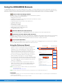 2
2
-
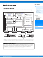 3
3
-
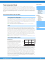 4
4
-
 5
5
-
 6
6
-
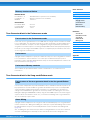 7
7
-
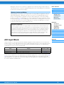 8
8
-
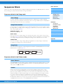 9
9
-
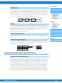 10
10
-
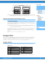 11
11
-
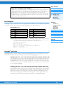 12
12
-
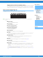 13
13
-
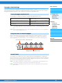 14
14
-
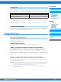 15
15
-
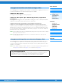 16
16
-
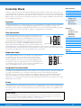 17
17
-
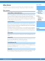 18
18
-
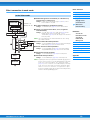 19
19
-
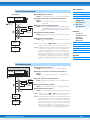 20
20
-
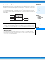 21
21
-
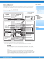 22
22
-
 23
23
-
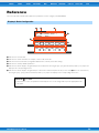 24
24
-
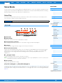 25
25
-
 26
26
-
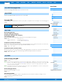 27
27
-
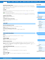 28
28
-
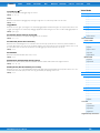 29
29
-
 30
30
-
 31
31
-
 32
32
-
 33
33
-
 34
34
-
 35
35
-
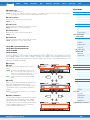 36
36
-
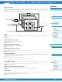 37
37
-
 38
38
-
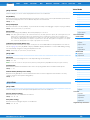 39
39
-
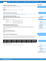 40
40
-
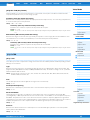 41
41
-
 42
42
-
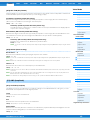 43
43
-
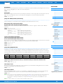 44
44
-
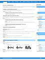 45
45
-
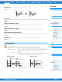 46
46
-
 47
47
-
 48
48
-
 49
49
-
 50
50
-
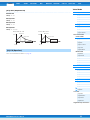 51
51
-
 52
52
-
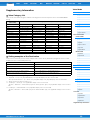 53
53
-
 54
54
-
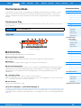 55
55
-
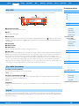 56
56
-
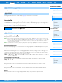 57
57
-
 58
58
-
 59
59
-
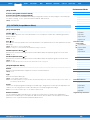 60
60
-
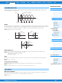 61
61
-
 62
62
-
 63
63
-
 64
64
-
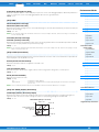 65
65
-
 66
66
-
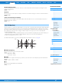 67
67
-
 68
68
-
 69
69
-
 70
70
-
 71
71
-
 72
72
-
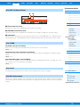 73
73
-
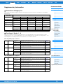 74
74
-
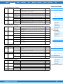 75
75
-
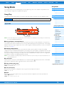 76
76
-
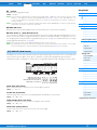 77
77
-
 78
78
-
 79
79
-
 80
80
-
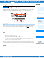 81
81
-
 82
82
-
 83
83
-
 84
84
-
 85
85
-
 86
86
-
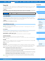 87
87
-
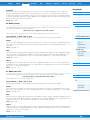 88
88
-
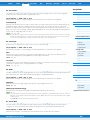 89
89
-
 90
90
-
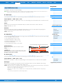 91
91
-
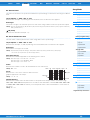 92
92
-
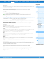 93
93
-
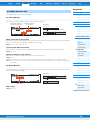 94
94
-
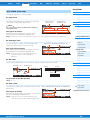 95
95
-
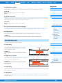 96
96
-
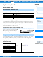 97
97
-
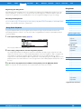 98
98
-
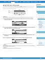 99
99
-
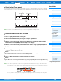 100
100
-
 101
101
-
 102
102
-
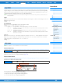 103
103
-
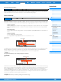 104
104
-
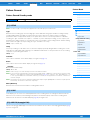 105
105
-
 106
106
-
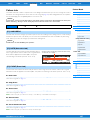 107
107
-
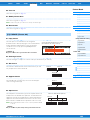 108
108
-
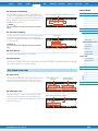 109
109
-
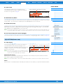 110
110
-
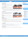 111
111
-
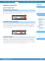 112
112
-
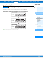 113
113
-
 114
114
-
 115
115
-
 116
116
-
 117
117
-
 118
118
-
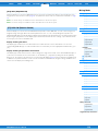 119
119
-
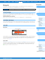 120
120
-
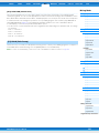 121
121
-
 122
122
-
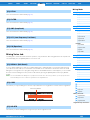 123
123
-
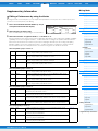 124
124
-
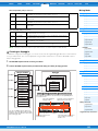 125
125
-
 126
126
-
 127
127
-
 128
128
-
 129
129
-
 130
130
-
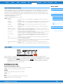 131
131
-
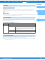 132
132
-
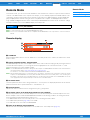 133
133
-
 134
134
-
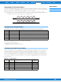 135
135
-
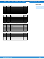 136
136
-
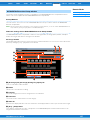 137
137
-
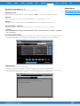 138
138
-
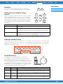 139
139
-
 140
140
-
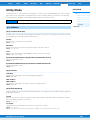 141
141
-
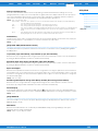 142
142
-
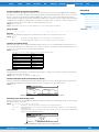 143
143
-
 144
144
-
 145
145
-
 146
146
-
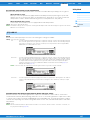 147
147
-
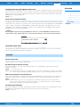 148
148
-
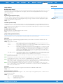 149
149
-
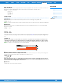 150
150
-
 151
151
-
 152
152
-
 153
153
-
 154
154
-
 155
155
-
 156
156
-
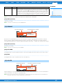 157
157
-
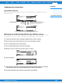 158
158
-
 159
159
-
 160
160


Yamaha MOX6 Manual de usuario
- Categoría
- Software
- Tipo
- Manual de usuario
- Este manual también es adecuado para
en otros idiomas
- français: Yamaha MOX6 Manuel utilisateur
- italiano: Yamaha MOX6 Manuale utente
- English: Yamaha MOX6 User manual
- Deutsch: Yamaha MOX6 Benutzerhandbuch
- русский: Yamaha MOX6 Руководство пользователя
- Nederlands: Yamaha MOX6 Handleiding
- português: Yamaha MOX6 Manual do usuário
- dansk: Yamaha MOX6 Brugermanual
- polski: Yamaha MOX6 Instrukcja obsługi
- čeština: Yamaha MOX6 Uživatelský manuál
- svenska: Yamaha MOX6 Användarmanual
- Türkçe: Yamaha MOX6 Kullanım kılavuzu
- suomi: Yamaha MOX6 Ohjekirja
- română: Yamaha MOX6 Manual de utilizare
Artículos relacionados
-
Yamaha XF6 Manual de usuario
-
Yamaha MOX6 El manual del propietario
-
-
-
-
-
-
-
-