Hobart G2SSMA77 Installation, Use And Maintenance Instructions
- Tipo
- Installation, Use And Maintenance Instructions

24/04/2007 Rev.4 167415
CUCINE A GAS SERIE DOMINA 700
SECONDO NORMA: EN 437 e EN 203 parte 1 e 2 Categoria II per Gas Metano e G.P.L..
GAS RANGE DOMINA 700 SERIES
ACCORDING TO: EN 437 and EN 203 part 1 and 2 Cat. II for Natural gas and L.P.G.
CUISINIERE AU GAZ SERIE DOMINA 700
CONFORME AUX NORMES: EN 437 et EN 203 1ère et 2ème partie pour Gaz Méthane et G.P.L.
GASHERDE SERIE DOMINA 700
NACH: EN 437 und EN 203 Teil 1 und 2 Kategorie II für Erdgas und Flüssiggas
COCINA A GAS SERIE DOMINA 700
SEGÚN: EN 437 y EN 203 parte 1 y 2. Categoría II: Metano y G.P.L.
0 6 9 4
G4SF77
G4SFA77
G4SF77P
G4SFE77
G4SFE77P
G6SFA77
G6SFEA77
G4SFEV77
G4SFEV77P
G6SFEVA77
G2SDMF77
G2SSMF77
G2SDMFE77
G2SSMFE77
G4SMFA77
G4SM77
G4SMA77
G2SSMA77
G2SDMA77
G2SSM77
G2SDM77
I
GB
F
D
E
ISTRUZIONI PER L’INSTALLAZIONE, L’USO E LA MANUTENZIONE
INSTALLATION, USE AND MAINTENANCE INSTRUCTIONS
INSTRUCTIONS POUR L’INSTALLATION, L’EMPLOI ET L’ENTRETIEN
INSTALLATIONS-, BETRIEBS-UND WARTUNGSANLEITUNGEN
INSTRUCCIONES PARA LA INSTALACIÓN, EL USO Y EL MANTENIMIENTO

- 2 -
I
CAPITOLO DESCRIZIONE PAGINA
INDICE
ITALIANO ................................................................................................ pagina 2 - 17
ENGLISH ................................................................................................. page 18 - 35
FRANÇAIS ............................................................................................... page 36 - 51
DEUTSCH ................................................................................................ Seite 52 - 69
ESPAÑOL ................................................................................................ página 70 - 86
Avvertenze generali ............................................................................................................................. 3
1. Dati tecnici .......................................................................................................................................... 4
1.1 Tabella I: Cucine a gas serie DOMINA 700 categoria II (Gas metano e G.P.L.) ................................ 4
1.2 Caratteristiche tecniche....................................................................................................................... 5
1.3 Forno GN2/1 ........................................................................................................................................ 5
1.4 Riscaldamento a gas ............................................................................................................................ 5
1.5 Riscaldamento elettrico ...................................................................................................................... 5
1.6 Piastra di cottura .................................................................................................................................. 5
2. Istruzioni per l’installazione ............................................................................................................... 6
2.1 Informazioni riguardanti le cucine a gas............................................................................................. 6
2.2 Leggi, norme e direttive tecniche ....................................................................................................... 6
2.3 Luogo di installazione ........................................................................................................................ 6
2.4 Posizionamento ................................................................................................................................... 6
2.5 Tabella II: Dati tecnici gas, pressione, ugelli bruciatore piccolo, pilota e vite del minimo
(cucine serie DOMINA 700) ............................................................................................................... 7
Tabella II: Dati tecnici gas, pressione, ugelli bruciatore medio 6kW, pilota e vite del minimo
(cucine serie DOMINA 700) ............................................................................................................... 7
Tabella II: Dati tecnici gas, pressione, ugelli bruciatore forno gn2/1, pilota e vite del minimo
(cucine serie DOMINA 700) .............................................................................................................. 8
Tabella II: Dati tecnici gas, pressione, ugelli bruciatore piastra di lenta cottura, pilota e vite del
minimo (cucine serie DOMINA 700).................................................................................................. 8
2.6 Collegamento all’impianto del gas ..................................................................................................... 8
2.6.1 Scarico dei prodotti di combustione sotto una cappa di aspirazione ................................................. 8
2.6.2 Come ottenere la portata termica nominale ........................................................................................ 8
2.7 Controllo della pressione .................................................................................................................... 9
2.7.1 Controllo della portata termica generale ............................................................................................ 9
2.7.2 Regolazione della portata termica minima ......................................................................................... 9
2.7.3 Controllo per il funzionamento a gas liquido .................................................................................... 9
2.7.4 Controllo del funzionamento .............................................................................................................. 9
2.8 Introduzione dell’utente ..................................................................................................................... 10
3. Collegamento elettrico........................................................................................................................ 10
3.1 Messa a tera ......................................................................................................................................... 10
3.2 Cavo d’alimentazione ......................................................................................................................... 10
3.3 Equipotenziale .................................................................................................................................... 10
3.4 Collegamento cavo elettrico ............................................................................................................... 11
3.5 Collegamenti alla rete elettrica di distribuzione ................................................................................ 11
3.5.5 Istruzioni elettriche ............................................................................................................................. 11
3.5.6 Uso forno elettrico statico ................................................................................................................... 11
3.5.7 Simbologia manopola forno ............................................................................................................... 11
3.5.8 Uso forno elettrico ventilato ............................................................................................................... 11
3.5.9 Simbologia della manopola forno ...................................................................................................... 12
3.6 Uso forno ventilato.............................................................................................................................. 12
4. Trasformazione per funzionamento ad altro tipo di gas ..................................................................... 13
4.1 Piano di cottura ................................................................................................................................... 13
4.2 Forno ................................................................................................................................................... 14
4.3 Piastra di cottura .................................................................................................................................. 14
5. Istruzioni per l’utente (accensione bruciatori) .................................................................................... 14
5.1 Uso del forno elettrico ......................................................................................................................... 15
6. Sostituzione dei componenti più importanti ...................................................................................... 16
6.1 Sostituzione dei componenti del forno elettrico ................................................................................ 17
7. Manutenzione e pulizia ...................................................................................................................... 17
SCHEMI DI INSTALLAZIONE ........................................................................................................... 87
SCHEMA DI ZOCCOLATURA CUCINE “DOMINA 700” ................................................................ 89
SCHEMA ELETTRICO ....................................................................................................................... 90

- 3 -
I
- Leggere attentamente le avvertenze contenute nel presente libretto in quanto forniscono importanti
indicazioni riguardanti la sicurezza di installazione, d’uso e di manutenzione.
- Conservare con cura questo libretto per ogni ulteriore consultazione dei vari operatori.
- Dopo aver tolto l’imballaggio, assicurarsi dell’integrità dell’apparecchiatura e in caso di dubbio, non utilizzare
l’apparecchiatura e rivolgersi a personale professionalmente qualificato.
- Prima di collegare l’apparecchiatura, accertarsi che i dati riportati sulla targhetta siano corrispondenti a quelli
della rete di distribuzione gas ed elettrica.
- Questa apparecchiatura deve essere destinata solo all’uso per il quale è stata espressamente concepita, ogni
altro uso è da considerarsi improprio e quindi pericoloso.
- L’apparecchiatura deve essere utilizzata solo da persona addestrata all’uso della stessa.
- Per eventuale riparazione rivolgersi solamente ad un centro di assistenza tecnica autorizzato dal costruttore e
richiedere l’utilizzo di ricambi originali.
- Il mancato rispetto di quanto sopra, può compromettere la sicurezza dell’apparecchiatura.
- Non lavare l’apparecchiatura con getti d’acqua diretti e ad alta pressione.
- Non ostruire le aperture o feritoie di aspirazione o di smaltimento del calore.
PER GLI APPARECCHI CON ALIMENTAZIONE ELETTRICA:
- La sicurezza elettrica è garantita soltanto da un efficace impianto di messa a terra, come previsto
dalle vigenti norme di sicurezza elettrica, è quindi necessario verificare questo fondamentale requisi
to, e in caso di dubbio, richiedere il controllo accurato da parte di personale professionalmente
qualificato.
- Il costruttore non può essere considerato responsabile per eventuali danni causati dalla mancanza di
messa a terra dell’impianto.
- L’apparecchiatura deve essere inclusa in un sistema equipotenziale la cui efficienza deve essere verificata
secondo le norme in vigore.
- Tutte le apparecchiature sono fornite di cavo, della lunghezza di cm. 200, con sezione sufficiente per il carico
massimo.
- Il cavo flessibile per l’allacciamento alla linea elettrica deve avere caratteristiche non inferiori al tipo con isola-
mento in gomma H07RN-F.
AVVERTENZE GENERALI
IN CASO DI INOSSERVANZA DELLE NORME CONTENUTE NEL PRESENTE MANUALE, SIA DA PARTE DEL-
L’UTENTE CHE DA PARTE DEL TECNICO ADDETTO ALL’INSTALLAZIONE, LA DITTA DECLINA OGNI RE-
SPONSABILITÀ ED OGNI EVENTUALE INCIDENTE O ANOMALIA CAUSATO DALLE SUDDETTE INOSSERVAN-
ZE NON POTRÀ ESSERE IMPUTATO ALLA STESSA.
LA CASA COSTRUTTRICE DECLINA OGNI RESPONSABILITÀ PER LE POSSIBILI INESATTEZZE CONTENU-
TE NEL PRESENTE OPUSCOLO, IMPUTABILI AD ERRORI DI TRASCRIZIONE O STAMPA. SI RISERVA INOL-
TRE IL DIRITTO DI APPORTARE AL PRODOTTO QUELLE MODIFICHE CHE SI RITENGONO UTILI O NECES-
SARIE, SENZA PREGIUDICARE LE CARATTERISTICHE ESSENZIALI.
Non lavare l’apparecchiatura con getti d’acqua diretti ad alta pressione
PROVVEDIMENTI NEL CASO IN CUI L’APPARECCHIATURA NON VENGA USATA PER MOLTO TEMPO.
Dopo aver pulito bene l’apparecchiatura, passare energicamente su tutte le superfici in acciaio un
panno appena imbevuto di olio di vaselina, in modo da stendere un velo protettivo.

- 4 -
I
1.1 TABELLA I: CUCINE A GAS SERIE DOMINA 700 CATEGORIA II (GAS METANO E G.P.L.)
A
700
735
850
985
G1/2"
–
–
1
520
620
310
2
2
–
1
–
–
25,0
1971/1942
2,646
3,077
–
A
700
735
850
985
G1/2"
–
–
1
520
620
310
2
2
–
–
–
1x5,3 kW
19,0
1498/1476
2,011
2,338
5,3
A
1100
735
850
985
G1/2"
–
–
1
520
620
310
2
2
–
1
–
–
25
1971/1942
2,646
3,077
–
A
1100
735
850
985
G1/2"
–
–
1
520
620
310
3
3
–
–
–
1x5,3 kW
28,5
2248/2214
3,016
3,508
5,3
A
700
735
850
985
G1/2"
320
585
1
560
620
310
1
1
1
1
–
–
21,0
1656/1631
2,222
2,585
–
A
1100
735
850
985
G1/2"
320
585
1
560
620
310
2
2
1
1
–
–
30,5
2405/2369
3,228
3,754
–
A
1100
735
850
958
G1/2"
–
–
1
520
620
310
–
4
–
1
–
–
30
2405/2369
3,175
3,693
–
A
1100
735
850
958
G1/2"
–
–
1
520
620
310
–
4
–
–
–
1x5,3 kW
24
1893/1864
2,540
2,954
5,3
G1/2"
–
–
–
–
–
–
2
2
1
–
–
–
24,5
1932/1903
2,593
3,151
–
A
700
735
850
985
G1/2"
–
–
–
–
–
–
1
1
1
–
–
–
15
1183/1165
1,587
1,846
–
* Tensione: 3N AC 380 - 415V 50-60 HZ per forno statico elettrico
Tipo
mm
mm
mm
mm
“A”
mm
mm
mm
mm
mm
3,5 kW
6,0 kW
5,5 kW
6,0 kW
2,6 kW
5,3 kW
kW
g/h
m
3
/h
m
3
/h
kW
A
700
735
850
985
G1/2"
320
585
1
560
620
310
1
1
1
–
–
1x5,3 kW
15,0
1183/1165
1,587
1,846
–
(1) Compreso la portata termica del pilota ca. 200 W
* Tensione: 1N AC 220...240 V 50 Hz per forno ventilato
Dimensioni esterne
Larghezza
Profondità
Altezza
Altezza massima
Attacco gas
Dimensioni piastra cottura
Larghezza
Profondità
Dimensioni forno GN2/1
N° forni
Larghezza
Profondità
Altezza
N° Bruciatori e portata termica
Piccolo (1)
Medio (1)
Piastra cottura (1)
Forno statico Gas (1)
Forno ventilato (elett.)
Forno statico (elett.)
Portata termica nom. totale
Consumo gas (15 °C)
G.P.L. G30/G31
Metano H-G20
Metano L-G25
Assorbimento
G4SF77 G4SFE77 G4SFA77 G6SFEA77
G2SDMF77
G2SSMF77
G2SDMFE77
G2SSMFE77
G4SMFA77
G4SF77P
G4SFEA77P
G2SDMA77
G2SSMA77
V = Forno Ventilato FE = Forno Elettrico Statico
G4SFEV77
A
1100
735
850
958
G1/2"
–
–
1
520
620
310
2
2
–
–
1x2,6 kW
–
19
1498/1476
2,011
2,338
2,6
G2SSM77
G2SDM77
A
700
735
250
330
G1/2"
–
–
–
–
–
–
1
1
1
–
–
–
15
1183/1165
1,587
1,846
–
*
A
1100
735
850
985
**
A
1200
735
250
330
*
G4SMA77
**
G4SM77
A
700
735
850
958
G1/2"
–
–
1
520
620
310
–
4
–
–
1x2,6 kW
–
24
1893/1864
2,540
2,954
2,6
G4SFEV77P
MODELLO
A
1100
735
850
958
G1/2"
–
–
1
520
620
310
3
3
–
–
1x2,6 kW
–
28,5
2248/2214
3,060
3.508
2,6
G6SFEVA77
1. DATI TECNICI

- 5 -
I
1.2 CARATTERISTICHE TECNICHE
STRUTTURA portante in acciaio inox AISI 304, pannellatura e basamento in acciaio inox, montata su piedini regolabili in
altezza.
PIANO LAVORO in acciaio inox AISI 304 a tenuta stagna.
GRIGLIE in fusione di ghisa porcellanata per alte temperature (RAL).
BRUCIATORI in ghisa cromata o smaltata, spartifiamma in ottone a fiamma stabilizzata, accensione con fiamma pilota,
ugelli fissi per i diversi tipi di gas.
RUBINETTI e TERMOSTATI in ottone stampato, dotati di valvola di sicurezza con termocoppia per l’interruzione automa-
tica del gas in caso di spegnimento accidentale del pilota. Regolazione tra portata minima e massima.
MANOPOLE RUBINETTI in materiale atermico.
1.3 FORNO GN2/1
CAMERA DI COTTURA in acciaio inox o smaltato resistente alle alte temperature e agli acidi, di dimensioni interne
conformi alle GASTRONORM 2/1. Isolamento termico con lana di vetro ad alta densità. Supporti laterali griglia in tondino
di acciaio cromato, facilmente estraibili per le pulizie. Griglia in acciaio cromato.
PORTE FORNO a doppia parete con intercapedine isolante in lana di vetro, controporte in acciaio inox, maniglie in acciao
satinato montate su supporti in materiale atermico e guarnizione di tenuta alla porta. Cerniere a molla bilanciate.
1.4 RISCALDAMENTO A GAS
Con bruciatore in acciaio inox a fiamma autostabilizzata. Regolazione termostatica della temperatura 150 ÷ 290 °C con
valvola di sicurezza con termocoppia per l’interruzione automatica del gas in caso di spegnimento accidentale del pilota.
Accensione piezoelettrica al pilota «Targhet» del forno.
1.5 RISCALDAMENTO ELETTRICO
Resistenze elettriche corrazzate in acciaio inossidabile si trovano nella camera di cottura.
Commutatore con termostato 50 ÷ 300 °C con le seguenti funzioni:
- Accensione forno
- Riscaldamento totale forno 5300 W
- Resistenza inferiore 3800 W
- Resistenza superiore 1500 W
Lampadine spia di controllo per indicare se il forno/grill è acceso e se il termostato richiede calore.
1.6 PIASTRA DI COTTURA
PIASTRA di cottura in ghisa ad alta conducibilità termica.
RISCALDAMENTO a gas mediante bruciatore in acciaio inossidabile a fiamma autostabilizzata che garantisce un’elevata
uniformità di riscaldamento della piastra. Regolazione termostatica della temperatura con valvola di sicurezza e termocoppia
per l’interruzione dell’afflusso del gas in caso di spegnimento accidentale del bruciatore pilota. Accensione piezo elettrico
al pilota “Targhet”.

- 6 -
I
2. ISTRUZIONI PER L’INSTALLAZIONE
L’installazione e l’eventuale trasformazione per l’uso di altri tipi di gas, deve essere eseguita da persone qualificate
secondo la normativa in vigore.
Vedere tabelle dati tecnici: 1.1 e 2.5
AVVERTENZE:
Nel caso in cui l’apparecchiatura venga installata contro una parete quest’ultima deve resistere ai valori di temperatura di
90°C e deve essere incombustibile.
Prima di procedere all’installazione, togliere dal rivestimento la pellicola di protezione in plastica, eliminando gli eventuali
residui adesivi con prodotto adatto alla pulizia per l’acciaio inossidabile.
Installare l’apparecchio in posizione orizzontale, la corretta posizione si otterrà ruotando i piedini livellatori.
Qualora l’apparecchiatura venga installata singolarmente si consiglia di fissarla per rendere più sicura la sua stabilità.
2.1 INFORMAZIONI RIGUARDANTI LE CUCINE A GAS SERIE DOMINA 700
Questo libretto è valido per le Cucine del
tipo A Categoria II (Gas naturale e Liquido
G.P.L.).
Vedere tabella 1.1 e 2.5
La targhetta secondo le norme EN437 e EN
203 parte 1 si trova:
a) sugli apparecchi con forno, sul pannello
anteriore-inferiore ed all’interno.
b) sugli apparecchi senza forno, nell’arma-
dio in basso a sinistra.
Esempio targhetta Italia: Cat. II 2H3+
Pe = Pressione a monte
Pi = Pressione all’ugello
2.2 LEGGI, NORME E DIRETTIVE TECNICHE
Per l’installazione sono da osservare le seguenti norme:
- Prescrizioni vigenti antinfortunistiche e antincendio.
- La regolamentazione dell’ente erogatore del gas, dal quale bisogna farsi rilasciare il nullaosta prima dell’installazione.
- Norme «Installazione impianti a gas».
- Norme «Installazione impianti elettrici».
- La regolamentazione dell’ente erogatore energia elettrica.
- Norme igieniche.
2.3 LUOGO D’INSTALLAZIONE
- L’apparecchio deve essere installato in locali con sufficiente areazione. Questo apparecchio richiede una aspirazione di
almeno 2 m
3
/h • kW P.T. (Portata Termica).
- Installare l’apparecchiatura secondo quanto previsto dalle norme di sicurezza UNI - CIG 8723, legge N° 46 del 5-3-’90 e
D.M. N° 74 del 12-10-96.
2.4 POSIZIONAMENTO
- Le varie apparecchiature possono essere installate singolarmente o possono essere accoppiate ad altre apparecchiature
della stessa gamma.
- Questa apparecchiatura non è idonea per l’incasso.
- La distanza dalla pareti laterali deve essere minimo di 10 cm., nel caso in cui la distanza fosse inferiore o il materiale delle
pareti o del pavimento fossero infiammabili, è indispensabile l’applicazione di un isolante termico.
V Hz kW
Type
tipo
Mod.
Matr.N°
Cat.
P n
Cat.
P n
PT
Qn
(Hi)
G20
G25
m
3
/h
m
3
/h
G30
G31
Kg/h
Kg/h
mbar
KW
mbar
II2H3B/P
20,50/50
II2L3B/P
25,30,30
NL AT-CH
II2H3B/P
20,30/30
II2H3+
PLIS-MT-CY FR - BE DE LUIT-GR-GB-ES-IE-PT
II2H3+
20,29/37
II2E+3+
20/25,29/37
II2ELL3B/P
20,20,50/50
I3B/P
30/30
II2E3P
20/37
I2E; I3+
20,29/37
20,50/67
NO-SE-EE-LT-DK-LV-CZ-SK-SI-FI-TR-HR-BG-RO

- 7 -
I
2.5 TABELLA II: DATI TECNICI GAS, PRESSIONE, UGELLI BRUCIATORE PICCOLO, PILOTA E VITE
DEL MINIMO (CUCINE SERIE DOMINA 700)
TABELLA II: DATI TECNICI GAS, PRESSIONE, UGELLI BRUCIATORE MEDIO 6KW, PILOTA E VITE
DEL MINIMO (CUCINE SERIE DOMINA 700)
Nazione
e
Categoria
Cat.
UGELLO
Tipo
di
GAS
PRESSIONE GAS
A MONTE mbar
Nom. Min. Max
BRUCIATORE
MEDIO
Ø mm
Tipo
MARCATO
R.d.A
X mm
ITALIA
II2H3+
ITALIA
II2H3+
2H
3+
G20
metano
G30
butano
G31
propano
20
29
37
17
20
25
25
35
45
175 K
115 K
F
F
BY-PASS
(21S)
Ø mm
MARCATO
PILOTA
1 VIA
Ø mm
MARCATO
Press. Gas
all’Ugello
con 21S
35
21
Max
mbar
Min.
mbar
Portata
Termica
nom. kW (1)
100% P. T.
Min.
ca.
Consumo
Gas
(15°C)
l/h g/h
19,7
28,7
36,9
2,4
4,8
5,7
6,0
6,0
2,15
2,1
634
186
243
-
473
466
(1) Compreso portata termica pilota circa 200W K = Ugello corto 15 mm. F= fisso
R.d.A. = Regolazione dell’aria primaria
110
75
115
75
PEL
COPRECI
Nazione
e
Categoria
Cat.
UGELLO
Tipo
di
GAS
PRESSIONE GAS
A MONTE mbar
Nom. Min. Max
BRUCIATORE
PICCOLO
Ø mm
Tipo
MARCATO
R.d.A
X mm
ITALIA
II2H3+
ITALIA
II2H3+
2H
3+
G20
metano
G30
butano
G31
propano
20
29
37
17
20
25
25
35
45
140 K
95 K
F
F
BY-PASS
(21S)
Ø mm
MARCATO
PILOTA
1 VIA
Ø mm
MARCATO
Press. Gas
all’Ugello
con 21S
35
21
Max
mbar
Min.
mbar
Portata
Termica
nom. kW (1)
100%
P. T.
Min.
ca.
Consumo
Gas
(15°C)
l/h
g/h
19,8
28,9
36,9
2,20
3,30
4,30
3,5
3,5
1,35
1,25
371
108
142
-
276
272
(1) Compreso portata termica pilota circa 200W K = Ugello corto 15 mm. F= fisso
R.d.A. = Regolazione dell’aria primaria
85
55
90
55
PEL
COPRECI

- 8 -
I
2.6 COLLEGAMENTO ALL’IMPIANTO DEL GAS
- L’apparecchio deve essere alimentato con gas avente le caratteristiche e la pressione riportata in Tabella II.
- La pressione del gas si misura alla presa di pressione iniziale con i bruciatori accesi (vedere Fig. 1 )
- L’apparecchiatura è collaudata e predisposta per funzionare a gas metano H G20 - 20 mbar.
* N.B. Se la pressione in rete varia più del +10% della pressione nominale, viene consigliato di montare un regolatore di
pressione a monte dell’apparecchio per garantire la pressione nominale.
- L’allacciamento alla rete del gas deve essere effettuato con tubazione metallica di adeguata sezione e deve essere inserito
a monte un rubinetto di intercettazione omologato.
- Dopo l’allacciamento alla rete del gas, controllare che non esistano perdite nei punti di raccordo con appositi strumenti o
acqua saponata.
2.6.1 SCARICO DEI PRODOTTI DI COMBUSTIONE SOTTO UNA CAPPA DI ASPIRAZIONE.
APPARECCHIO DEL TIPO: A1
L’apparecchiatura a gas va sistemata sotto una cappa di aspirazione il cui impianto deve avere le caratteristiche conformi alle
Norme. Questo apparecchio necessita di almeno 2 m
3
/h • kW P.T. (P.T. = Portata Termica).
Controllare l’aerazione della cucina; deve essere secondo le norme in vigore.
2.6.2 COME OTTENERE LA PORTATA TERMICA NOMINALE
Controllare se l’apparecchio è predisposto per il tipo di gas, pressione e categoria che corrisponde con il gas disponibile in
rete. Indicazione riportata sull’imballo e/o targhetta sull’apparecchio.
TABELLA II: DATI TECNICI GAS, PRESSIONE, UGELLI BRUCIATORE FORNO GN2/1, PILOTA E
VITE DEL MINIMO (CUCINE SERIE DOMINA 700)
TABELLA II: DATI TECNICI GAS, PRESSIONE, UGELLI BRUCIATORE PIASTRA DI LENTA
COTTURA, PILOTA E VITE DEL MINIMO (CUCINE SERIE DOMINA 700)
(1) Compreso portata termica pilota circa 200W K = Ugello corto 15 mm. F= fisso
R.d.A. = Regolazione dell’aria primaria
Nazione
e
Categoria
Cat.
UGELLO
Tipo
di
GAS
PRESSIONE GAS
A MONTE mbar
Nom. Min. Max
BRUCIATORE
FORNO
Ø mm
Tipo
MARCATO
R.d.A
X mm
ITALIA
II2H3+
ITALIA
II2H3+
2H
3+
G20
metano
G30
butano
G31
propano
20
29
37
17
20
25
25
35
45
185 K
125 K
15
15
BY-PASS
(22S)
Ø mm
MARCATO
PILOTA
1 VIA
“targhet”
MARCATO
Press. Gas
all’Ugello
con 25ST
36
19
Max
mbar
Min.
mbar
Portata
Termica
nom. kW (1)
100%
P. T.
Min.
ca.
Consumo
Gas
(15°C)
l/h
g/h
18,4
28,7
36,9
1,3
1,8
2,5
6,0
6,0
1,55
1,55
634
186
245
-
473
466
95
65
95
65
PEL SARAF
Nazione
e
Categoria
Cat.
UGELLO
Tipo
di
GAS
PRESSIONE GAS
A MONTE mbar
Nom. Min. Max
BRUCIATORE
PIASTRA
Ø mm
Tipo
MARCATO
R.d.A
X mm
ITALIA
II2H3+
ITALIA
II2H3+
2H
3+
G20
metano
G30
butano
G31
propano
20
29
37
17
20
25
25
35
45
170K
115K
20
20
BY-PASS
(22S)
Ø mm
MARCATO
PILOTA
1 VIA
“targhet”
MARCATO
Press. Gas
all’Ugello
con 25ST
95
65
27
19
Max
mbar
Min.
mbar
Portata
Termica
nom. kW (1)
100% P. T.
Min.
ca.
Consumo
Gas
(15°C)
l/h g/h
19,2
28,8
36,8
1,5
2,4
3
5,5
5,5
1,55
1,55
582
170
223
-
433
427
(1) Compreso portata termica pilota circa 200W K = Ugello corto 15 mm. F= fisso
R.d.A. = Regolazione dell’aria primaria

- 9 -
I
Se l’apparecchio è predisposto per un altro tipo di gas e pressione, occorre prima fare una trasformazione per il funzionamento
ad altro tipo di gas. Vedere la Tabella II per l’ugello, vite del minimo (by-pass), regolazione dell’aria primaria, (X mm),
l’ugello del pilota e la pressione all’ugello del bruciatore principale.
N.B.: I nomi degli ugelli «2H» e «3+» sono visibili nella parte sinistra della Tabella II.
2H = G 20 - 20 mbar
3 + = G 30 - 29 mbar e/o G 31 - 37 mbar una coppia di gas e pressione.
Nella Tabella II sono riportati i tipi di gas e pressione per tutti i bruciatori e i relativi ugelli, la distanza X mm della
regolazione dell’aria primaria (vedere Fig. 4), la vite del minimo (by-pass), l’ugello del pilota, la pressione massima e
minima all’ugello, la portata termica massima e minima e il consumo gas in l/h (15°C) o in g/h in caso di G.P.L.
Attenzione: Se la pressione «dinamica» del gas a monte dell’apparecchio è inferiore alla pressione minima della Tabella II,
l’allacciamento è proibito; l’installatore deve comunicare all’azienda del gas che la pressione in rete è troppo bassa.
N.B.: Se la pressione varia più del +10% della pressione nominale p.e. per G 20- 22 mbar viene consigliato di montare un
regolatore di pressione a monte dell’apparecchio per garantire la pressione nominale.
Se la pressione in rete è oltre la pressione massima della Tabella II p.e. per G 20 - 25 mbar avvertire l’azienda del gas.
Controllare se la pressione in entrata ed all’ugello corrisponde con i valori riportati nella Tabella II.
2.7 CONTROLLO DELLA PRESSIONE
CONTROLLO DELLA PRESSIONE A MONTE (Pe) Fig. 1
La pressione viene misurata con un manometro 0 ÷ 80 mbar (Precisione almeno 0,1 mbar).
La presa di pressione Fig. 1 si trova sulla rampa gas G 1/2" dietro il cruscotto; svitare la vite (A) della presa di pressione (B),
attaccare la gomma al silicone nel manometro, accendere il bruciatore e rilevare la pressione «dinamica» a monte.
Rimontare la vite (A) con rondella di tenuta gas (C), controllare la tenuta gas con bolle di sapone.
CONTROLLO DELLA PRESSIONE ALL’UGELLO (Pi) Fig. 2.
La presa di pressione si trova sopra il porta ugello (Fig. 2).
La gomma al silicone è adatta per alte temperature ma va protetta con carta stagnola.
2.7.1 CONTROLLO DELLA PORTATA TERMICA “GENERALE”
Una eventuale trasformazione per il funzionamento ad altro tipo di gas (vedere Cap. 4) deve essere eseguita da un installatore
o assistente autorizzato. La portata termica da controllare può essere:
- la portata termica nominale riportata sulla targhetta
- la portata termica massima in posizione massima
- la portata termica minima in posizione minima.
Controllare prima di tutto se l’apparecchio è già predisposto per il gas e la pressione distribuita in rete, in caso di trasformazio-
ne per il funzionamento ad altro tipo di gas controllare bene la marcatura sugli ugelli, la vite del minimo e by-pass con le
Tabelle II Iniettori Cap. 2.5
2.7.2 REGOLAZIONE DELLA PORTATA TERMICA MINIMA
La portata termica minimo giusto, viene ottenuta con la vite del minimo by-pass «calibrata» avvitata a fondo secondo la
Tabella II Iniettori Cap. 2.5
Il forno va scaldato almeno per 20 minuti portando la manopola del termostato in posizione di massimo, poi girare la
manopola al minimo. Controllare la pressione all’ugello e la portata termica minima.
2.7.3 CONTROLLO PER IL FUNZIONAMENTO A GAS LIQUIDO
Controllare se gli ugelli montati corrispondono con l’indicazione delle Tabelle II Iniettori Cap. 2.5
Verificare se la pressione in entrata corrisponde con le indicazioni della Tabella II.
Controllare se l’impianto a gas G.P.L. ha due regolatori di pressione di sufficiente capacità e se la capacità di evaporazione
dell’impianto può essere considerata sufficiente.
Vedere anche la pubblicazione «Norme di installazione e caratteristiche di Impianti a gas G.P.L.».
2.7.4 CONTROLLO DEL FUNZIONAMENTO
- Mettere l’apparecchio in funzione secondo le istruzioni d’uso.
- Controllare che non ci siano delle perdite di gas secondo le normative locali.
- Controllare l’accensione e l’interaccensione del bruciatore pilota e bruciatore principale.
- Verificare lo scarico regolare dei gas della combustione.

- 10 -
I
- Incollare una targhettina adesiva sulla targhetta della apparecchiatura per quale gas e pressione l’apparecchio è stato regolato.
2.8 INTRODUZIONE DELL’UTENTE
Spiegare il funzionamento e l’uso della Cucina all’utente utilizzando il libretto istruzioni e illustrare eventuali cambiamenti.
Lasciare il libretto istruzioni in mano all’utente e spiegare che lo deve utilizzare per ulteriori consultazioni.
SOLO PER APPARECCHI CON FORNO ELETTRICO)
L’allacciamento elettrico dev’essere eseguito nel rispetto delle norme CEI, solo da personale autorizzato e competente.
In primo luogo esaminare i dati riportati nella tabella dati tecnici del presente libretto, nella targhetta e nello schema elettrico.
L’allacciamento previsto è del tipo fisso.
La posizione della morsettiera, a cui si accede smontando il fianco sinistro è riportata, per ogni modello, nel presente libretto
e sul basamento del forno stesso.
IMPORTANTE: A monte di ogni apparecchiatura è necessario prevedere un dispositivo di interruzione omnipolare della
rete, che abbia una distanza di contatti di almeno 3 mm., esempio:
- interruttore manuale di adatta portata, corredato di valvole fusibile
- interruttore automatico con relativi relè magnetotermici.
3.1 MESSA A TERRA
E’ indispensabile collegare a terra l’apparecchiatura.
A tale proposito è necessario collegare i morsetti contraddistinti dai simboli ( ) posti sulla morsettiera arrivo linea ad una
efficace terra, realizzata conformemente alle norme in vigore.
AVVERTENZE SPECIFICHE
La sicurezza elettrica di questa appartecchiatura è assicurata soltanto quando la stessa è correttamente collegata ad
un efficace impianto di messa a terra come previsto dalle vigenti norme di sicurezza elettrica; il costruttore declina,
ogni responsabilità qualora queste norme antinfortunistiche non vengano rispettate.
E’ necessario verificare questo fondamentale requisito di sicurezza e, in caso di dubbio, richiedere un controllo accurato
dell’impianto da parte di personale professionalmente qualificato.
Il costruttore non può essere considerato responsabile per eventuali danni causati dalla mancanza di messa a terra
dell’impianto.
ATTENZIONE: NON INTERROMPERE MAI IL CAVO DI TERRA (Giallo-verde).
3.2 CAVO D’ALIMENTAZIONE
L’apparecchiatura viene consegnata predisposta per la seguente tensione, 1N AC 220...240 V 50 Hz.
Il cavo flessibile per l’allacciamento alla linea elettrica deve essere di caratteristiche non inferiori al tipo con isolamento in
gomma H07RN-F. Il cavo deve essere introdotto attraverso il ferma cavo e fissato bene. Inoltre la tensione di alimentazione,
ad apparecchio funzionante, non deve discostarsi dal valore della tensione nominale ± 10%.
3.3 EQUIPOTENZIALE
L’apparecchiatura deve essere inclusa in un sistema equipotenziale la cui efficienza deve essere verificata secondo le norme
in vigore. La vite contrassegnata con la targhetta «Equipotenziale» si trova vicina alla morsettiera sul basamento.
3. COLLEGAMENTO ELETTRICO

- 11 -
I
PE (Terra) giallo-verde
N (NP) azzurro
L
1
(R) marrone
AC 220...240 V 50 Hz
Elementi 240 V
PE (Terra) giallo-verde
N (NP) azzurro
L
3
(T) nero
L
2
(S) nero
L
1
(R) marrone
3N AC 380...415 V 50/60 Hz
3.5 COLLEGAMENTI ALLA RETE ELETTRICA DI DISTRIBUZIONE
* = 230V ~ 50/60 Hz
AVVERTENZE
- Prima di accendere il forno, accertarsi che non vi siano all’interno del vano sacchetti di plastica, carta, cartone, ecc.
3.5.8 USO DEL FORNO ELETTRICO VENTILATO
- Girare la manopola (Pos. A - Fig. 2) in senso orario impostando la temperatura desiderata.
- La spia verde si accenderà indicando l’accensione del forno.
- L’accensione della spia arancione (Pos. C - Fig. 2) indica l’entrata in funzione del termostato e quindi che il forno sta
richiedendo calore; quando all’interno della camera di cottura viene raggiunta la temperatura desiderata corrispondente a
quella impostata nella manopola (Pos. A - Fig. 2) la spia arancio si spegne e si possono quindi introdurre nel forno gli
alimenti da cuocere.
Durante questa fase è necessario chiudere completamente la porta.
- A fine cottura spegnere il forno, ruotando la manopola sullo “ 0 “ in corrispondenza dell’indice.
Forno spento
Elemento superiore acceso 1500 W
Elemento inferiore 3800 W
con controllo termostatico 100 ÷ 290 °C
Fig. 2
3.5.5 ISTRUZIONI ELETTRICHE
3.5.6 USO DEL FORNO ELETTRICO STATICO
3.5.7 SIMBOLOGIA DELLA MANOPOLA FORNO
TIPO DI TENSIONE
3N AC 380 - 415 V 50-60 HZ
4 x 2,5
N° cavi
mm
2
Mass.
A/f
MODELLO
G4SFE77 G4SFE77P G6SFEA77 G4SFEV77 G4SFEV77P4SFEVA77
16,5
N° cavi
mm
2
Mass.
A/f
1N AC 220 - 240 V 50-60 HZ
3 x 2,5
11,3
3.4 COLLEGAMENTO CAVO ELETTRICO
CD

- 12 -
I
3.6 USO DEL FORNO VENTILATO
- Girare la manopola (Pos. A - Fig. 3) in senso orario impostando la temperatura desiderata.
- La spia verde si accenderà indicando l’accensione del forno.
- L’accensione della spia arancione (Pos. C - Fig. 3) indica l’entrata in funzione del termostato e quindi che il forno sta
richiedendo calore; quando all’interno della camera di cottura viene raggiunta la temperatura desiderata (corrispondente a
quella impostata nella manopola (Pos. A - Fig. 3) la spia accensione si spegne e si possono quindi introdurre nel forno gli
alimenti da cuocere. Durante questa fase è necessario chiudere completamente la porta.
- A fine cottura spegnere il forno, ruotando la manopola sullo “ 0 “ in corrispondenza dell’indice.
CARATTERISTICHE DEL FORNO VENTILATO
Il riscaldamento del forno viene ottenuto con una resistenza posteriore e da un motoventilatore che fa circolare uniformemente
all’interno della camera di cottura aria calda.
La temperatura all’interno del forno viene mantenuta costantemente da un termostato che spegne resistenza quando si è
raggiunta la temperatura impostata e la riaccende quando questa è scesa di qualche grado.
COTTURA CON IL FORNO VENTILATO
Grazie alla ventilazione omogenea di aria calda all’interno del forno si possono cuocere diversi tipi di cibo sui 3 ripiani di cui è
munita la griglia laterale, inoltre con il sistema ad aria calda la cottura avviene più rapidamente rispetto a quella effettuata con un
forno statico. Tenere perciò presente di ridurre di 15° ÷ 20°C la temperatura di cottura riportata normalmente nei libri di cucina.
COTTURA ALLA GRIGLIA
Impostare nella manopola comando forno (Pos. A - Fig. 3) la temperatura di cottura desiderata, quindi aspettare il raggiungimento
di tale temperature indicate dallo spegnimento della spia arancione (Pos. C - Fig. 3).
Introdurre ora nel forno appoggiandolo sopra alla griglia (posizionata sul gradino centrale) il pezzo di carne da cuocere
leggermente unto d’olio, quindi infilare sotto alla griglia un vassoio raccoglisughi onde evitare di sporcare eccessivamente il
forno.
L’aria calda che avvolge completamente il cibo da cuocere in tutte le sue parti, provoca una rapida rosolatura esterna bloccan-
do all’interno i sughi dell’alimento; non è perciò assolutamente necessario girare il cibo durante la cottura.
IMPORTANTE: prima di usare il forno per la prima volta è opportuno riscaldarlo alla massima temperatura per una durata di
30 - 40 minuti a porta chiusa, in modo da bruciare eventuali residui oleosi che potrebbero sviluppare odori sgradevoli.
Fig. 3
3.5.9 SIMBOLOGIA DELLA MANOPOLA FORNO
( O ) Forno spento
Elemento ventilatore
AVVERTENZE
- Prima di accendere il forno, accertarsi che non vi siano
all’interno del vano sacchetti di plastica, carta, carto-
ne, ecc.
70
0
270
230
200
150
100

- 13 -
I
4. TRASFORMAZIONE PER FUNZIONAMENTO AD ALTRO TIPO DI GAS
CONSIGLI PRATICI PER LA COTTURA AL FORNO VENTILATO
Importante: I tempi e le temperature sono orientativi e potranno essere interpretati in relazione all’esperienza ed ai gusti
personali.
Minestre
Cannelloni ripieni
Lasagne
Pasticcio di maccheroni o cappelletti
Flan di uova
Carni
Vitello arrosto (kg. 1)
Arrosto di agnello
Arrosto di maiale
Fagiano arrosto
Pollo
Pesce (kg. 1)
Pasticceria
Biscotti con lievito
Pasta frolla
Meringhe
Pan di Spagna
Torta di frutta
Focaccia
Sterilizzazione di frutta
Sterilizzazione di verdure
Pizza
Pane
Cibi
Temperatura °C
Tempo minuti
130
150
175
175
160
160
170
160
160
170
160
175
100
150
150
150
200
200
220
250
20
50
45
25
120 - 150
60 - 90
50 - 60
60 - 90
60 - 90
30 - 40
20 - 25
20 - 25
30 - 35
20 - 25
50 - 60
40 - 50
20 - 30
20 - 30
20 - 30
20 - 30
4.1 PIANO DI COTTURA
- Togliere le griglie, spartifiamme e il corpo bruciatore
- Smontare il frontalino.
- Togliere le manopole
SOSTITUZIONE UGELLO BRUCIATORE DI PLACCA
Sostituire l’ugello (Fig. 2 pos. 2) del bruciatore (chiave del 12) con quello corrispondente al tipo di gas prescelto attenendosi
alle Tabelle II Iniettori Cap. 2.5
SOSTITUZIONE UGELLO BRUCIATORE PILOTA DI PLACCA
- Smontare le due piastrine di bloccaggio (Fig. 3 pos. 3) con una chiave a brugola di 4 mm.
- Sollevare la testa del bruciatore pilota (Fig. 3 pos. 5).
- Sostituire l’ugello (Fig. 3 pos. 4) del bruciatore pilota usando la chiave del 5 con quello corrispondente al tipo di gas
prescelto attenendosi alla Tabella II Iniettori Cap. 2.5
- Prima di montare la testa (Fig. 3 pos. 5) regolare l’aria primaria girando il suo regolatore (Fig. 3 pos. 6). Accendere il pilota
e controllare la lunghezza e la qualità della fiamma che deve essere non troppo fiacca ma neanche troppo tesa e lunga circa
20 mm, staccandosi quasi dalla testa ma senza provocare una punta gialla. (Gas G.P.L.).
SOSTITUZIONE VITE DEL MINIMO “BY PASS”
- Sostituire la vite della portata termica minima, by-pass (Fig. 2 pos. 1) con quella corrispondente al tipo di gas prescelto
attenendosi alla Tabella II Iniettori Cap. 2.5
- La portata termica in posizione di minimo deve essere circa 30% della portata termica nominale. Quando si gira la manopola
veloce dalla posizione massima ( ) alla posizione minima ( ) il bruciatore non deve spegnersi o ritornare.

- 14 -
I
5. ISTRUZIONI PER L’UTENTE
4.2 FORNO
SOSTITUZIONE UGELLO BRUCIATORE FORNO
Dopo aver tolto il piano del forno; smontare la scatola di protezione.
Sostituire l’ugello del bruciatore con una chiave del 12 (Fig. 4 pos. 4) con quello corrispondente al tipo di gas prescelto
attenendosi alla Tabella II Iniettori Cap. 2.5
SOSTITUZIONE UGELLO BRUCIATORE PILOTA
N.B.: Si consiglia di smontare subito la candeletta per evitare di romperla.
Svitare il dado con una chiave 10 mm. (Fig. 4 pos. 2) e smontare l’ugello (Fig. 4 pos. 1). L’ugello è agganciato al bicono
(Fig. 4 pos. 3). Sostituire l’ugello pilota (Fig. 4 pos. 1) con quello corrispondente al gas prescelto secondo quanto riportato nella
Tabella II Iniettori Cap. 2.5. Stringere bene il dado con una chiave da 10 mm., e controllare la tenuta gas con bolle di sapone.
REGOLAZIONE DEL MINIMO BRUCIATORE FORNO
Sostituire la vite del minimo (Fig. 5 pos. 11) situata sul termostato con quella corrispondente al tipo di gas prescelto Tabella
II Iniettori Cap. 2.5. Girare fino in fondo la vite del minimo o by-pass.
L’aria primaria viene regolata impostando il regolatore dell’aria primaria (Fig. 4 pos. 8) secondo quanto riportato sulla Tabella
II Iniettori Cap. 2.5
Dopo aver regolato la distanza, bloccare con la vite; rimontare la protezione dopo aver montato la vite della presa di
pressione.
4.3 PIASTRA DI COTTURA
SOSTITUZIONE UGELLO BRUCIATORE PILOTA
N.B.: Si consiglia di smontare subito la candeletta per evitare di romperla.
Per cambiare l’iniettore del pilota, occorre svitare il dado (Fig. 6 pos. 7) con una chiave del 10 e sostituire l’iniettore (Fig. 6
pos. 6) con quello corrispondente al tipo di gas prescelto e indicato nella Tabella II Iniettori Cap. 2.5
SOSTITUZIONE UGELLO BRUCIATORE PIASTRA
Sostituire l’ugello del bruciatore (Fig. 6 pos. 1) con quello corrispondente al tipo di gas prescelto e indicato nella Tabella II
Iniettori Cap. 2.5 . Accendere il bruciatore pilota (Fig. 6 pos. 5) portando la manopola Fig. 8 nella posizione ( ), accendere
il bruciatore (Fig. 6 pos; 4) portando la manopola in posizione 8, allentare la vite (Fig. 6 pos. 2) e regolare la fiamma agendo
sulla bussola di regolazione (Fig. 6 pos. 3), per ogni tipo di gas regolare l’aria primaria (R.d.A) di X mm (vedi Tabella II
Iniettori Cap. 2.5).
SOSTITUZIONE VITE DEL MINIMO “BY-PASS”
Sostituire la vite del minimo (Fig. 5 pos. 11) situata sul termostato con quello corrispondente al tipo di gas prescelto attenen-
dosi alla Tabella II Iniettori Cap. 2.5 Girare fino in fondo la vite del minimo o by-pass.
Terminata la sostituzione degli ugelli, applicare sopra alla targhetta esistente quella data in dotazione alla macchina
indicante il nuovo tipo di gas.
ACCENSIONE BRUCIATORE DI PLACCA (PIANO DI COTTURA)
Per accendere il pilota di placca, premere la manopola (Fig. 7) ruotandola verso sinistra fino al simbolo ( ) raggiunta la
posizione premere a fondo e procedere all’accensione del pilota. Mantenere premuta la manopola per circa 20 secondi; al suo
rilascio, la fiammella del pilota deve rimanere accesa, se ciò non avvenisse ripetere l’operazione. Per accendere il bruciatore
ruotare la manopola in posizione ( ) per il massimo ed in posizione ( ) per il minimo. Per spegnere completamente i
bruciatori, portare la manopola in posizione ( ).
NOTE: si consiglia l’utilizzo della griglia di riduzione sul bruciatore
RECIPIENTI CONSIGLIATI
Tipo di bruciatore 6 kw 3.5 kw
Diametro min. consigliato 220 mm 200mm
Diametro max. consigliato 380 mm 300 mm

- 15 -
I
AVVERTENZE
- Prima di accendere il forno, accertarsi che non vi siano nel vano forno sacchetti di plastica, carta, cartone, ecc.
- Inserire l’interruttore generale dell’impianto elettrico.
- Ruotare la manopola del forno in senso orario per l’accensione portandola in corrispondenza della temperatura desiderata.
- Durante i funzionamento Grill, la porta del forno deve rimanere aperta.
USO DEL FORNO
- Girare la manopola in senso orario e impostare la temperatura desiderata, la spia gialla e quella verde si accenderanno.
- Attendere che si spenga la spia gialla, a questo punto il forno è in temperatura, inserire ora i cibi e chiudere la porta.
Controllare periodicamente lo stato di cottura dei cibi.
- A fine cottura spegnere il forno, girando la manopola in senso contrario, portandola sullo “ 0 “.
N.B.: E’ possibile anche una cottura differenziata, concentrando il calore o nella parte superiore o nella parte inferiore
del forno.
Girando la manopola verso destra e ponendola in corrispondenza del simbolo ( ) si accende la resistenza superiore di 1500
W di potenza; ruotandola in corrispondenza dei 290 ° C si accendono entrambe le resistenze superiore ed inferiore.
Forno spento
Elemento superiore acceso 1500 W
Elemento superiore e inferiore 5,3 kW
con controllo termostatico 100 ÷ 290 °C
ACCENSIONE BRUCIATORI PIASTRA DI COTTURA
- Per accendere il pilota della piastra di cottura, premere la manopola (Fig. 9) ruotandola verso sinistra fino al simbolo ( )
raggiunta la posizione premere a fondo e procedere all’accensione del pilota schiacciando contemporaneamente il pulsan
te dell’accensione piezoelettrica; il pulsante si trova sul cruscotto. Il bruciatore pilota è visibile attraverso l’oblò sul
cruscotto.
Mantenere premuta la manopola per circa 20 secondi; al suo rilascio, la fiammella del pilota deve rimanere accesa. Se ciò
non avvenisse, ripetere l’operazione di accensione.
- Per accendere e regolare il bruciatore, girare la manopola nella posizione desiderata, tenendo presente che alle posizioni da
8 a 1 corrisponde una temperatura della piastra di circa:
POS. 8 = 260°C POS. 4 = 165°C
POS. 7 = 235°C POS. 3 = 165°C
POS. 6 = 210°C POS. 2 = 165°C
POS. 5 = 185°C POS. 1 = 165°C
- Per spegnere il bruciatore, riportare la manopola in posizione ( ) per lo spegnimento totale, riportare la manopola in
posizione ( )
ACCENSIONE BRUCIATORI FORNO
- Per accendere il pilota del forno, premere la manopola (Fig. 8) ruotandola verso sinistra fino al simbolo ( ) raggiunta la
posizione premere a fondo e procedere all’accensione del pilota schiacciando contemporaneamente il pulsante dell’accen-
sione piezoelettrica. Il bruciatore pilota è visibile attraverso l’oblò sul fondo del forno. Mantenere premuta la manopola per
circa 20 secondi; al suo rilascio, la fiammella del pilota deve rimanere accesa. Se ciò non avvenisse, ripetere l’operazione
di accensione.
- Per accendere e regolare il bruciatore, girare la manopola nella posizione desiderata.
- Per spegnere il bruciatore, riportare la manopola in posizione ( ) per lo spegnimento totale, riportare la manopola in
posizione ( ).
5.1 USO DEL FORNO ELETTRICO
FUNZIONAMENTO FORNO ELETTRICO E SIMBOLOGIA NELLA MANOPOLA (FIG. 9)
CD

- 16 -
I
L’apparecchio deve essere controllato almeno 2 volte all’anno. Sono da controllare il bruciatore, l’accensione, interaccensione,
l’impostazione del massimo e del minimo.
Da effettuarsi solo da un “Centro Assistenza Autorizzato”!!.
Per poter cambiare i seguenti componenti si deve per prima cosa:
- chiudere il rubinetto gas in entrata;
- togliere la manopole;
- smontare il frontalino;
- eventualmente togliere le griglie, gli spartifiamma e i bruciatori.
Adesso si possono sostituire i componenti più importanti.
A) Termocoppia bruciatore piano di lavoro (Fig. 3)
- smontare il dado (7) con una chiave del 8
- smontare il dado (Fig. 2 pos. 3) con una chiave del 9
- montare una nuova termocoppia dello stesso tipo seguendo l’ordine inverso di smontaggio
B) Rubinetto piano di lavoro (Fig. 2)
- smontare il dado (3) con una chiave del 9;
- smontare tutti gli attacchi gas (4-5-6)
- montare un nuovo rubinetto seguendo l’ordine inverso di smontaggio
N.B.: Controllare che non vi siano fughe di gas usando bolle di sapone, la tenuta deve essere perfetta.
C) Termostato forno (Fig. 5) “Solo per gli apparecchi con forno a gas”.
Il termostato si trova sulla rampa di alimentazione gas.
- smontare la termocoppia (16) con una chiave del 9;
- smontare per primo l’uscita del gas verso i bruciatori (13 e 15);
- smontare il bulbo che si trova all’interno del forno e viene fissato con squadrette porta bulbo;
- smontare l’entrata del gas (12) con una chiave del 19;
- montare il nuovo termostato seguendo l’ordine inverso di smontaggio;
- cambiare la vite del minimo “By-pass” (11);
- montare il bulbo nel forno usando le sue squadrette.
N.B.: Controllare che non vi siano fughe di gas usando bolle di sapone, la tenuta deve essere perfetta.
D) Termocoppia forno (Fig. 4 pos. 6 e Fig. 5 pos. 16)
- togliere il fondo del forno;
- smontare la scatola di protezione;
- smontare il dado sul termostato con una chiave del 9 (Fig. 5 pos. 16);
- smontare il dado (Fig. 4 pos. 6) con una chiave del 10;
- montare una termocoppia targhet nuova seguendo l’ordine inverso di smontaggio.
N.B.: Termocoppia unificata SIT: da tenere 4 o 5 mm indietro rispetto al suo fermo.
E) Candeletta bruciatore pilota forno (Fig. 4 pos. 5)
- eliminare il fondo del forno;
- smontare la scatola di protezione;
- staccare il cavo dell’alta tensione;
- smontare la candeletta svitando il dado (5) con una chiave del 10;
- montare una nuova candeletta seguendo l’ordine inverso di smontaggio.
F) Accenditore piezoelettrico forno e/o piastra
E’ molto semplice smontare l’accenditore dal cruscotto;
- staccare il cavo dell’alta tensione;
- svitare il dado con una chiave del 25;
- montare l’accenditore nuovo seguendo l’ordine inverso di smontaggio.
6. SOSTITUZIONE DEI COMPONENTI PIÙ IMPORTANTI

- 17 -
I
6.1 SOSTITUZIONE DEI COMPONENTI DEL FORNO ELETTRICO
“Solo per i modelli con un forno elettrico”.
Le sostituzioni sotto riportate vanno eseguite solo da un “Centro Assistenza Autorizzato”!!.
Prima di eseguire la sostituzione dei vari componenti si deve:
- togliere la tensione dall’apparecchio con l’interruttore onnipolare;
- staccare la manopola rossa del termostato elettrico;
- smontare il frontalino;
- smontare eventualmente il fondo del forno;
- smontare eventualmente la porta del forno.
Ora si possono sostituire i componenti più importanti:
A) Interruttore e termostato del forno.
Prendere il frontalino in mano.
- smontare le due viti M5;
- staccare il termostato dal commutatore; il termostato è agganciato al commutatore attraverso una squadretta;
- piegare con cura le due linguette e staccare il termostato dal commutatore;
- smontare il bulbo all’interno del vano forno. Il bulbo è fissato con due squadrette;
- staccare i fili consultando lo schema elettrico;
- montare il nuovo commutatore e il nuovo termostato utilizzando lo schema elettrico e seguendo l’ordine inverso di
smontaggio.
Attenzione: il commutatore e il termostato devono essere a terra (fili giallo-verde).
B) Resistenze del forno
Si possono smontare gli elementi dall’interno del vano forno;
- staccare i fili consultando lo schema elettrico;
- montare la nuova resistenza utilizzando lo schema elettrico e seguendo l’ordine inverso di smontaggio.
Attenzione: le resistenze devono essere collegate a terra (fili giallo-verde).
C) Termostato limite forno
Il termostato limite può essere sostituito solo da un “Centro di Assistenza Autorizzato”!!
- Pulire giornalmente la parti in acciaio inox con acqua tiepida saponata, quindi risciacquare abbondantemente ed asciugare
con cura.
- Evitare nel modo più assoluto di pulire l’acciaio inox con paglietta, spazzola o raschietti di acciaio comune in quanto
possono depositare particelle ferrose che ossidandosi provocano punti di ruggine. Può essere eventualmente adoperata
lana di acciaio inossidabile passata nel senso della satinatura.
- Qualora l’apparecchiatura non venga utilizzata per lunghi periodi, passare energicamente su tutte le superfici in acciaio un
panno appena imbevuto di olio di vaselina, in modo da stendere un velo protettivo. Arieggiare periodicamente i locali.
PIASTRA DI COTTURA
Pulire frequentemente la piastra usando uno strofinaccio umido, successivamente metterla in funzione per qualche minuto
posizionando le manopole al massimo allo scopo di asciugarla nel più breve tempo possibile. Al termine lubrificarla con un
leggero strato di olio di vaselina.
PARTI IN ACCIAIO INOSSIDABILE
Anche i particolari in acciaio inox debbono essere puliti con acqua saponata e poi asciugati con un panno morbido.
La lucentezza viene mantenuta mediante ripassatura periodica, con detergente liquido, un prodotto reperibile ovunque
PARTI SMALTATE
Per mantenere a lungo la lucentezza delle parti smaltate, è necessario pulirle frequentemente con acqua saponata tiepida.
Non permettere che l’aceto, il caffè, il latte, l’acqua salina, il succo di limone e di pomodoro rimangano per lungo tempo a
contatto con la superficie smaltata.
7. MANUTENZIONE E PULIZIA

- 18 -
GB
CHAPTER DESCRIPTION PAGE
INDEX
General remarks ................................................................................................................................... 19
1. Technical data ..................................................................................................................................... 20
1.1 Table I: Gas range DOMINA 700 series, category II (Natural gas and L.P.G.) .................................. 20
1.2 Technical characteristics ..................................................................................................................... 21
1.3 Oven .................................................................................................................................................... 21
1.4 Gas heating .......................................................................................................................................... 21
1.5 Electrical heating ................................................................................................................................ 21
1.6 Gas solid top ........................................................................................................................................ 21
2. Installation instructions ...................................................................................................................... 22
2.1 Information about gas range ............................................................................................................... 22
2.2 Laws, regulations and technical directives to be complied with ........................................................ 22
2.3 Installation place ................................................................................................................................. 22
2.4 Positioning .......................................................................................................................................... 22
2.5 Table II: Gas technical data, pressure, small burner 3,5 kW nozzles, pilot and idle screw
for gas range DOMINA 700 series ....................................................................................................... 23
Table II: Gas technical data, pressure, medium burner 6 kW nozzles, pilot and idle screw
for gas range DOMINA 700 series ....................................................................................................... 24
Table II: Gas technical data, pressure, oven burner 6 kW nozzles, pilot and idle screw
for gas range DOMINA 700 series ....................................................................................................... 24
Table II: Gas technical data, pressure, solid top burner nozzles, pilot and idle screw
(valid for all gas range DOMINA 700 series) ...................................................................................... 25
2.6 Gas system connection ........................................................................................................................ 25
2.6.1 Discharge of exhaust flue products under a draft hood ......................................................................25
2.6.2 How to achieve the nominal thermal capacity.................................................................................... 25
2.7 Pressure check ..................................................................................................................................... 25
2.7.1 Checking the general thermal capacity .............................................................................................. 26
2.7.2 Adjusting the minimum thermal capacity .......................................................................................... 26
2.7.3 Liquid gas operation control ............................................................................................................... 26
2.7.4 Operation control ................................................................................................................................ 26
2.8 Introduction to users ........................................................................................................................... 26
3. Electrical connection .......................................................................................................................... 27
3.1 Earthing ............................................................................................................................................... 27
3.2 Power supply cable.............................................................................................................................. 27
3.3 Equipotential....................................................................................................................................... 27
3.4 Electrical cable connection ................................................................................................................. 27
3.5 Connections to various main power supplies ..................................................................................... 28
3.5.5 Electric instruction .............................................................................................................................. 28
3.5.6 Using the static electric oven .............................................................................................................. 28
3.5.7 Oven knob symbol .............................................................................................................................. 28
3.5.8 Using the ventilated electric oven ...................................................................................................... 28
3.5.9 Oven knob symbols ............................................................................................................................. 29
3.6 Using the ventilated oven ................................................................................................................... 29
Some practical advice for cooking with the ventilated oven ............................................................. 30
4. Trasformation to operate with other gas type ..................................................................................... 31
4.1 Cooktop............................................................................................................................................... 31
4.2 Oven .................................................................................................................................................... 31
4.3 Cooking plate ...................................................................................................................................... 32
5. Instructions to users ............................................................................................................................. 32
5.1 Using the electric oven........................................................................................................................ 33
6. Replacing important components ....................................................................................................... 34
6.1 Replacing electric oven components .................................................................................................. 35
7. Maintenance and cleaning .................................................................................................................. 35
INSTALLATION DIAGRAM ............................................................................................................... 87
“DOMINA 700” KITCHEN BASEBOARD DIAGRAM ...................................................................... 89
ELECTRICAL DIAGRAM .................................................................................................................. 90

- 19 -
GB
- Carefully read the instructions contained in the present booklet as they supply important information
relating to safe installation, use and maintenance.
- Keep this booklet with care, for any further consultation by the various operators.
- Having removed the packing, make sure the unit is in good order and in case of doubt, do not use the unit, but call
on skilled personnel.
- Before connecting the unit, make sure the data appearing on the label correspond to those of the main gas supply.
- This unit must only be destined to the use it was expressely built for; any other use must be deemed improper
and therefore dangerous.
- The unit must be used only by a person trained for its operation.
- For any repairs, please call exclusively a technical service centre authorised by the manufacturer, and ask for
original spare parts only.
- The non-compliance of the above can compromise unit safety.
- Do not wash the unit with direct or high-pressure water jets.
- Do not obstruct openings or draft grids or heat vents.
FOR ELECTRICALLY POWERED UNITS:
- electrical safety is guaranteed only by an efficient earthing system, as envisaged by the electrical safety
regulation in force: it is therefore necessary to verify this essential requisite and, in case of doubt,
request an accurate check-up by professionally qualified personnel.
- the Manufacturer cannot be deemed responsible for any damages caused by the lack of earthing in the
system.
- the unit must be included in an equipotential system whose efficiency should be tested in compliance with the
law in force.
- all units are supplied with a 200cm long cable having a sufficient cross section for the maximum load.
- the hookup wire for the power supply connection should not have characteristics below the type with rubber
insulation H07RN-F
GENERAL REMARKS
IN CASE OF NON-COMPLIANCE WITH THE INDICATIONS CONTAINED IN THE PRESENT MANUAL, BOTH ON
THE USER’S PART AND ON THE INSTALLING TECHNICIAN’S PART, THE MANUFACTURER DECLINES ANY
ESPONSIBILITY, AND ANY POSSIBLE ACCIDENT OR FAULT CAUSED BY THE ABOVE MENTIONED NON-
COMPLIANCES WILL NOT BE IMPUTABLE TO THE MANUFACTURER.
THE MANUFACTURER DECLINES ANY RESPONSIBILITY FOR ANY IMPRECISIONS APPEARING ON THE
PRESENT BOOKLET, ASCRIBABLE TO TRANSCRIPTION OR PRINTING ERRORS. FURTHERMORE, THE
MANUFACTURER RESERVES THE RIGHT TO MAKE ANY MODIFICATIONS TO THE PRODUCT DEEMED
USEFUL OR NECESSARY, WITHOUT PREJUDICING ITS ESSENTIAL CHARACTERISTICS.
Do not wash the equipment with direct high-pressure water jets
MEASURES TO BE TAKEN WHEN THE EQUIPMENT IS NOT USED FOR A LONG TIME.
After cleaning the equipment well, wipe thoroughly all the steel surfaces with a cloth slightly soaked in
Vaseline oil and apply a thin protective coat.

- 20 -
GB
1.1 TABLE I: GAS RANGE DOMINA 700 SERIES, CATEGORY II (NATURAL GAS AND L.P.G.)
1. TECHNICAL DATA
A
700
735
850
985
G1/2"
–
–
1
520
620
310
2
2
–
1
–
–
25,0
1971/1942
2,646
3,077
–
A
700
735
850
985
G1/2"
–
–
1
520
620
310
2
2
–
–
–
1x5,3 kW
19,0
1498/1476
2,011
2,338
5,3
A
1100
735
850
985
G1/2"
–
–
1
520
620
310
2
2
–
1
–
–
25
1971/1942
2,646
3,077
–
A
1100
735
850
985
G1/2"
–
–
1
520
620
310
3
3
–
–
–
1x5,3 kW
28,5
2248/2214
3,016
3,508
5,3
A
700
735
850
985
G1/2"
320
585
1
560
620
310
1
1
1
1
–
–
21,0
1656/1631
2,222
2,585
–
A
1100
735
850
985
G1/2"
320
585
1
560
620
310
2
2
1
1
–
–
30,5
2405/2369
3,228
3,754
–
A
1100
735
850
958
G1/2"
–
–
1
520
620
310
–
4
–
1
–
–
30
2405/2369
3,175
3,693
–
A
1100
735
850
958
G1/2"
–
–
1
520
620
310
–
4
–
–
–
1x5,3 kW
24
1893/1864
2,540
2,954
5,3
G1/2"
–
–
–
–
–
–
2
2
1
–
–
–
24,5
1932/1903
2,593
3,151
–
A
700
735
850
985
G1/2"
–
–
–
–
–
–
1
1
1
–
–
–
15
1183/1165
1,587
1,846
–
Tipo
mm
mm
mm
mm
“A”
mm
mm
mm
mm
mm
3,5 kW
6,0 kW
5,5 kW
6,0 kW
2,6 kW
5,3 kW
kW
g/h
m
3
/h
m
3
/h
kW
A
700
735
850
985
G1/2"
320
585
1
560
620
310
1
1
1
–
–
1x5,3 kW
15,0
1183/1165
1,587
1,846
–
G4SF77 G4SFE77 G4SFA77 G6SFEA77
G2SDMF77
G2SSMF77
G2SDMFE77
G2SSMFE77
G4SMFA77
G4SF77P
G4SFEA77P
G2SDMA77
G2SSMA77
G4SFEV77
A
1100
735
850
958
G1/2"
–
–
1
520
620
310
2
2
–
–
1x2,6 kW
–
19
1498/1476
2,011
2,338
2,6
G2SSM77
G2SDM77
A
700
735
250
330
G1/2"
–
–
–
–
–
–
1
1
1
–
–
–
15
1183/1165
1,587
1,846
–
*
A
1100
735
850
985
**
A
1200
735
250
330
*
G4SMA77
**
G4SM77
A
700
735
850
958
G1/2"
–
–
1
520
620
310
–
4
–
–
1x2,6 kW
–
24
1893/1864
2,540
2,954
2,6
G4SFEV77P
MODEL
A
1100
735
850
958
G1/2"
–
–
1
520
620
310
3
3
–
–
1x2,6 kW
–
28,5
2248/2214
3,060
3.508
2,6
G6SFEVA77
(1) Including the pilot’s thermal capacity approx. 200W
* Voltage: 1N AC 220...240 V 50 Hz
for ventilated oven
External dimensions
Width
Depth
Height
Maximum Height
Gas Connection
Cooking Plate dimensions
Width
Depth
Dimensioni forno GN2/1
N° forni
Width
Depth
Height
Burners No. and Thermal Capacity
Small (1)
Medium (1)
Cooking Plate (1)
Static oven (1)
ventilated oven
Electric Static oven
Total nominal thermal capacity
Gas consumption (15 °C)
G.P.L. G30/G31
Natural Gas H-G20
Natural Gas L-G25
Absorption *
* Voltage: 3N AC 380 - 415V 50-60 HZ for static electric oven
V = Ventilated oven FE = Static electric oven

- 21 -
GB
1.2 TECHNICAL CHARACTERISTICS
STRUCTURE Stainless steel frame AISI 304, stainless steel panels and base mounted on height-adjustable feet.
TOP in stainless steel AISI 304 seal tight.
GRILLS in porcelained cast iron, high-temperature resistant.
BURNERS in chromate or enamelled cast iron flame-spreader made of brass with stabilised fire, ignition by pilot flame, fixed
nozzles for various types of gas.
GAS COCKS-THERMOSTATS in pressed brass, supplied with safety valve and thermocouple for automatic interruption of
gas flow in case of accidental pilot extinguishment.
CONTROL KNOBS in heat-insulated material.
1.3 OVEN
COOKING CHAMBER in high-temperature and acid resistant porcelained steel or enamelled steel , with internal dimensions
complying to GASTRONORM 2/1. Thermal insulation with high-density glass wool. Grill’s lateral supports made of chromate
steel bars, easily extractable for cleaning. Grill made of chromate steel bar.
OVEN DOORS with double panelling and insulating glass wool interspace, door headers of stainless steel, handles in satin
steel mounted on athermal supports, and door seal. Balanced spring hinges.
1.4 GAS HEATING
Stainless steel burner with self-stabilising flame. Thermostat adjustable temperature 150÷290°C with safety valve and
thermocouple for automatic gas interruption in case of accidental pilot extinguishment.
Piezoelectric ignition of the oven’s “Targhet” pilot.
1.5 ELECTRICAL HEATING
Electrical resistors reinforced in stainless steel are located in the cooking chamber.
Selector switch with 50÷300°C thermostat and the following functions:
- Oven ignition
- Full oven heating 5300 W
- Lower resistor 3800 W
- Upper resistor 1500 W
Signal lamps indicating whether the oven/grill is on and the thermostat needs heating increase.
1.6 GAS SOLID TOP
COOKING PLATE in cast iron with high thermal conductivity.
GAS HEATING by means of self-adjusting flame burners made of stainless steel, guaranteeing highly uniform plate heating.
Thermostat temperature control with safety valve and thermocouple to cut off the flow of gas if the pilot burner is accidentally
extinguished. Piezoelectric ignition of the pilot “targhet”.
.

- 22 -
GB
Installation and any transformation for using other types of gas, must be performed by qualified technicians according
to the law in force.
See technical data tables: 1.1 and 2.5
WARNINGS:
Should the unit be installed against a wall, the latter must be heat resistant to temperatures of 90°C and must be fireproof.
Before proceeding with the installation, remove the protective plastic film from the relevant parts, eliminating any adhesive
residues with an appropriate cleaning product suitable for stainless steel.
Install the unit in a horizontal position; its correct levelling will be achieved by rotating the adjustable feet.
If the unit is installed by itself, it is advisable to fasten it to make its stability safer.
2.1 INFORMATION ABOUT GAS RANGE DOMINA 700 SERIES
This manual applies to our Gas Range, Type
A1 Category II (Natural Gas and L.P.G.).
See table 1.1 and 2.5.
The label according to EN437 and EN203
regulations, Part 1, is located:
a) for the units with oven, on the front-lower
panel
b) for the units with no oven, in the cabinet’s
low-left side
Example for Italy label: Category II 2H3÷
Pe= Incoming Pressure
Pi= Nozzle Pressure
2.2 LAWS, REGULATIONS AND
TECHNICAL DIRECTIVES TO BE COMPLIED WITH
The following indications should be observed during installation:
- Accident and fire regulations in force
- Prescriptions by the Gas Supply Company, which should issue an authorisation before installation.
- Instructions for the “Installation of gas equipment”
- Instructions for the “Installation of electrical equipment”
- Prescriptions by the Electrical Supply Company
- Hygienic regulations.
2.3 INSTALLATION PLACE
- The unit should be installed in adequately ventilated places. (This unit requires a draft of at least 2cu.m/hr l kW T.C.
(Thermal Capacity).
- Install the equipment in compliance with the safety rules applicable in the country where the equipment is installed.
2.4 POSITIONING
- The various units may be installed individually or together with other units of our range.
- This unit is not suitable for encasing.
- The distance between side walls must be a minimum of 10cm; should the distance be less or the wall or floor material be
flammable, it is essential to use a thermal insulator.
2. INSTALLATION INSTRUCTIONS
V Hz kW
Type
tipo
Mod.
Matr.N°
Cat.
P n
Cat.
P n
PT
Qn
(Hi)
G20
G25
m
3
/h
m
3
/h
G30
G31
Kg/h
Kg/h
mbar
KW
mbar
II2H3B/P
20,50/50
II2L3B/P
25,30,30
NL AT-CH
II2H3B/P
20,30/30
II2H3+
PLIS-MT-CY FR - BE DE LUIT-GR-GB-ES-IE-PT
II2H3+
20,29/37
II2E+3+
20/25,29/37
II2ELL3B/P
20,20,50/50
I3B/P
30/30
II2E3P
20/37
I2E; I3+
20,29/37
20,50/67
NO-SE-EE-LT-DK-LV-CZ-SK-SI-FI-TR-HR-BG-RO

- 23 -
GB
Nation
and
category
Cat.
Nozzle
Type
of
gas
ENG, ICEL, DENIM,
FIN, SWED, PORT,
GREECE, IRELAND
NETHERLANDS
NETHERLANDS
ICEL,
DENMARK,
FINLAND,
SWEDEND,
NORWAY
IRELAND
PORTUGAL
ENGLAND
GREECE
LUXEMBURG
2H
2L
3B/P
3+
G20
G25
G30*
G31
G30*
G31
Gas pressure
upstream
mbar
Nom. Min. Max.
20
25
29
29
37
17
20
25
20
25
25
30
35
35
45
SMALL
BURNER
Ø mm. Type
MARKED
R.d.A.
X mm.
BY-PASS
(21 S)
Ø mm.
MARKED
PILOT
Ø mm.
MARKED
140 K
140/250 K
95K
95 K
F
F
F
F
85
85
55
55
35
35
21
21
Gas
pressure at
nozzle
with 21S
Max.
mbar
Min.
mbar
Nominal
Thermal
kW (1)
100% T.C.
Min.
Gas
consumption
15°C
l/h g/h
19,8
24,6
28,9
28,9
36,9
2,2
3,0
3,3
3,3
4,3
3,5
3,5
3,5
3,5
1,35
1,25
1,25
1,25
371
431
108
125
108
142
-
-
276
239
276
272
R.o.A. = Regulation of primary air (1) Including the pilot thermal capacity approx. 400W. Nozzle marking Ø 1/100
* Pressure regulator excluded K = Short nozzle l = 15 mm F = Fixed A = Adjustable TA = Open all
90
90
55
55
PEL
COPRECI-
2.5 TABLE II: GAS TECHNICAL DATA, PRESSURE, SMALL BURNER 3,5 KW NOZZLES, PILOT AND
IDLE SCREW FOR GAS RANGE DOMINA 700 SERIES

- 24 -
GB
TABLE II: GAS TECHNICAL DATA, PRESSURE, OVEN 6KWBURNER NOZZLES, PILOT AND IDLE
SCREW FOR GAS RANGE DOMINA 700 SERIES
ENG, ICEL, DENIM,
FIN, SWED, PORT,
GREECE, IRELAND
NETHERLANDS
NETHERLANDS
ICEL,
DENMARK,
FINLAND,
SWEDEND
NORWAY
IRELAND
PORTUGAL
ENGLAND
GREECE
LUXEMBURG
R.o.A. = Regulation of primary air (1) Including the pilot thermal capacity approx. 400W. Nozzle marking Ø 1/100
* Pressure regulator excluded K = Short nozzle l = 15 mm F = Fixed A = Adjustable TA = Open all
TABLE II: GAS TECHNICAL DATA, PRESSURE, MEDIUM BURNER 6KW NOZZLES, PILOT AND
IDLE SCREW FOR GAS RANGE DOMINA 700 SERIES
ENG, ICEL, DENIM,
FIN, SWED, PORT,
GREECE, IRELAND
NETHERLANDS
NETHERLANDS
ICEL,
DENMARK,
FINLAND,
SWEDEND
NORWAY
IRELAND
PORTUGAL
ENGLAND
GREECE
LUXEMBURG
R.o.A. = Regulation of primary air (1) Including the pilot thermal capacity approx. 400W. Nozzle marking Ø 1/100
* Pressure regulator excluded K = Short nozzle l = 15 mm F = Fixed A = Adjustable TA = Open all
Nation
and
category
Cat.
Nozzle
Type
of
gas
2H
2L
3B/P
3+
G20
G25
G30*
G31
G30*
G31
Gas pressure
upstream
mbar
Nom. Min. Max.
20
25
29
29
37
17
20
25
20
25
25
30
35
35
45
OVEN
BURNER
Ø mm. Type
MARKED
R.d.A.
X mm.
BY-PASS
(22 S)
Ø mm.
MARKED
PILOT
“targhet”
MARKED
185 K
190/250 K
125 K
125 K
15
15
15
15
95
95
65
65
36
36
19
19
Gas
pressure at
nozzle
with 25ST
Max.
mbar
Min.
mbar
Nominal
Thermal
kW (1)
100% T.C.
Min.
Gas
consumption
15°C
l/h g/h
18,4
22,5
28,7
28,7
36,9
1,3
1,7
1,8
1,8
2,5
6,0
6,0
6,0
6,0
1,55
1,55
1,55
1,55
634
738
186
215
86
245
-
-
473
403
473
466
PEL SABAF
95
99
65
65
Nation
and
category
Cat.
Nozzle
Type
of
gas
2H
2L
3B/P
3+
G20
G25
G30*
G31
G30*
G31
Gas pressure
upstream
mbar
Nom. Min. Max.
20
25
29
29
37
17
20
25
20
25
25
30
35
35
45
MEDIUM
BURNER
Ø mm. Type
MARKED
R.d.A.
X mm.
BY-PASS
(21 S)
Ø mm.
MARKED
PILOT
Ø mm.
MARKED
175 K
185/250 K
115 K
115 K
F
F
F
F
110
115
75
75
35
35
21
21
Gas
pressure at
nozzle
with 21S
Max.
mbar
Min.
mbar
Nominal
Thermal
kW (1)
100% T.C.
Min.
Gas
consumption
15°C
l/h g/h
19,7
24,2
28,9
28,9
36,9
2,4
3,4
4,4
4,4
5,7
6,0
6,0
6,0
6,0
635
739
186
214
186
245
-
-
473
410
473
466
2,1
2,1
2,1
2,1
PEL
COPRECI
115
120
75
75

- 25 -
GB
R.o.A. = Regulation of primary air (1) Including the pilot thermal capacity approx. 400W. Nozzle marking Ø 1/100
* Pressure regulator excluded K = Short nozzle l = 15 mm F = Fixed A = Adjustable TA = Open all
TABLE II: GAS TECHNICAL DATA, PRESSURE, SOLID TOP BURNER NOZZLES, PILOT AND IDLE
SCREW (VALID FOR ALL GAS RANGE DOMINA 700 SERIES)
The gas unit should be installed under a draft hood whose system ought to have characteristics complying with Regulations.
(This unit requires a draft of at least 2cu.m/hr l kW T.C. (T.C.= Thermal Capacity).
Check kitchen aeration: it should be in compliance with law in force.
2.6.2 HOW TO ACHIEVE THE NOMINAL THERMAL CAPACITY
Check whether the unit is fitted for the gas type, pressure and category corresponding with the main gas supply.
Indication shown on packing and/or the label of the unit.
If the unit is fitted for another gas type or pressure, you need to first effect a change over to the other gas type.
See Table II for the nozzle, the idle screw (bypass), the primary air regulation, (X mm), the pilot nozzle and the nozzle pressure
for the main burner.
N.B.: The names of nozzles “2H” and “3+” are shown on the left side of Table II.
2H= G20 - 20mbar
3+= G30 29mbar and/or G31 - 37mbar coupled gas and pressure.
Table II shows the types of gas and pressure for all burners and respective nozzles, the X mm distance for the adjustment of
primary air (see Fig. 3), the idle screw (bypass), the pilot nozzle, the maximum and minimum pressure at nozzle, the maximum
and minimum thermal capacity, and the gas consumption in l/hr (15°C) or in g/hr in the case of L.P.G.
Attention: If the incoming gas’ “dynamic” pressure to the unit is lower than the minimum pressure on Table II, connection is
prohibited; furthermore, the fitter should notify the gas Company that the supply pressure is too low.
N.B.: Should the pressure vary more to than +10% of the nominal pressure, e.g. for G20- 22mbar, it is advisable to mount a
pressure regulator ahead of the unit in order to guarantee the nominal pressure.
Should the supply pressure exceed the maximum pressure on Table II, e.g. for G20- 25mbar, notify the gas Company.
Make sure the inlet and nozzle pressures agrees with the values shown on Table II.
2.7 PRESSURE CHECK
INCOMING PRESSURE CHECK (Pe) Fig. 1
Pressure is measured with a manometer 0 ÷ 80mbar (precision at least 0.1mbar).
The pressure socket Fig. 1 is located on the G 1/2" gas ramp behind the panel; undo the screw (A) of the pressure socket (B),
attach the silicone rubber to the manometer, ignite the burner (Fig. 3 position 4) and take the incoming “dynamic” pressure.
Fasten the screw (A) back with a gas washer (C), check gas sealing with bubble soap.
1,55
1,40
1,55
1,55
Nation
and
category
Cat.
Nozzle
Type
of
gas
ENG, ICEL, DENIM,
FIN, SWED, PORT,
GREECE, IRELAND
NETHERLANDS
NETHERLANDS
ICEL,
DENMARK,
FINLAND,
SWEDEND
NORWAY
IRELAND
PORTUGAL
ENGLAND
GREECE
LUXEMBURG
2H
2L
3B/P
3+
G20
G25
G30*
G31
G30*
G31
Gas pressure
upstream
mbar
Nom. Min. Max.
20
25
29
29
37
17
20
25
20
25
25
30
35
35
45
SOLID TOP
BURNER
Ø mm. Type
MARKED
R.d.A.
X mm.
BY-PASS
(22 S)
Ø mm.
MARKED
PILOT
“targhet”
MARKED
170K
175/250K
115K
115K
20
20
20
20
95
95
65
65
Gas
pressure at
nozzle
with 25ST
Max.
mbar
Min.
mbar
Nominal
Thermal
kW (1)
100% T.C.
Min.
Gas
consumption
15°C
l/h g/h
5,5
5,5
5,5
5,5
27
27
19
19
19,2
23,6
28,8
28,8
36,8
1,5
1,8
2,4
2,4
3,0
582
676
170
196
170
223
-
-
433
376
433
427

- 26 -
GB
NOZZLE PRESSURE CHECK
The pressure intake is over the nozzle (Fig. 29).
The silicone rubber is prepared for high temperatures and should be protected with tin foil to avoid its burning.
2.7.1 CHECKING THE “GENERAL” THERMAL CAPACITY
Any transformation for another type of gas (see Ch. 4) should be performed by an authorised fitter or assistant.
The thermal capacity to be checked could be:
- the nominal thermal capacity shown on the data label
- the maximum thermal capacity in the maximum position
- the minimum thermal capacity in the minimum position.
First of all, check whether the unity is already fitted for gas main and pressure; in case of transformation for operating with
other gas type, carefully check the nozzles markings, the idle screw and bypass referring to the Table II Injectors Ch. 2.5
2.7.2 ADJUSTING THE MINIMUM THERMAL CAPACITY
The right minimum for thermal capacity is achieved by means of the “calibrated” bypass idle screw firmly tightened in
accordance with Table II Injectors Ch. 2.5
The oven should be heated up for at least 20 minutes by bringing the thermostat in the maximum position ,then turn the knob
to the minimum.
2.7.3 LIQUID GAS OPERATION CONTROL
Check whether the fitted nozzles comply with the indications on Table II, Ch. 2.5
Check whether the incoming pressure complies with the indications on Table II.
Make sure that the L.P.G. gas system has two pressure regulators of suitable capacity and that the evaporation capacity is
sufficient. See also the publication “Installation Regulations and Characteristics of L.P.G. Systems”.
2.7.4 OPERATION CONTROL
- Start the unit in accordance with the use instructions.
- Make sure there are no leaks following the local procedures.
- Check the ignition and interignition of the pilot burner and the main burner.
- Make sure the flue gases are discharged regularly.
- Write on a sticker, to be glued to the unit label, for what gas and pressure the unit has been calibrated
2.8 INTRODUCTION TO USERS
Explain the operation and use to the user by consulting the manual, and illustrate any changes.
Leave the manual in the user’s hands and explain the he/she should use it for further reference.

- 27 -
GB
3. ELECTRICAL CONNECTION
FOR UNITS WITH ELECTRIC OVEN ONLY
Electrical connection should be performed in compliance with the CEI regulations, only by authorised and competent
personnel. In the first instance, examine the data shown on the technical data table of this manual, on the label and on the
electrical diagram. The envisaged connection is of the fixed type. The position of the terminal box, accessible by removing
the left side, is explained, for each model, on the present manual and on the oven base itself.
IMPORTANT: Ahead of each unit it is necessary to install an omnipolar main breaker, having a spacing among contacts of
at least 3mm; example:
- manual breaker of appropriate capacity, complete with fuse valves
- automatic breaker with respective magnetothermal relays.
3.1 EARTHING
It is essential to earth the unit.
To this purpose, it is necessary to connect to an efficient earthing system the terminals marked with the symbols ( ) placed
on the line-receiving terminal box. The earthing system should comply with the law in force.
SPECIFIC WARNINGS
The electrical safety of this unit is assured only when it is correctly connected to an efficient earthing system as stated in
the electrical safety regulations in force; the Manufacturer declines any responsibility for the non-compliance with these
safety regulations.
It is necessary to verify this fundamental safety requisite and, in case of doubt, ask for an accurate testing of the system by
professionally qualified personnel.
The Manufacturer cannot be deemed responsible for any damages caused by the lack of unit earthing.
ATTENTION: NEVER INTERRUPT THE EARTH WIRE (Yellow-Green)
3.2 POWER SUPPLY CABLE
The unit is supplied fitted for the following voltages: 3N AC 380...415V; 3 AC 220...240V; 1N AC 220...240V 50Hz.
The flexible cable for power supply connection should not have characteristics lower than the rubber insulation type H07RN-F.
The cable should be inserted through the cable clasp and firmly fastened. Furthermore, the supply voltage with the unit
functioning should not go outside the value of the nominal tension ±10%.
3.3 EQUIPOTENTIAL
The unit should be included within an equipotential system whose efficiency must be tested according to the law in force.
The screw marked with the label “Equipotential” is located near the terminal box on the base.
3.4 ELECTRICAL CABLE CONNECTION
- To ignite the plaque pilot, press the knob (Fig. 7) turning it to the left to reach the symbol ( ); having reached this
position, press the knob deeply down and ignite the pilot.
- Keep the knob pressed for approx. 20 seconds; when released, the pilot flame should stay on. Should it go off, repeat the
ignition operation.
- To ignite the burner, turn the knob to position ( ) for the maximum, and to position ( ) for the minimum. To shut off the
burners completely, bring the knob to position ( ).

- 28 -
GB
SUPPLY VOLTAGE TYPE
3N AC 380 - 415 V 50-60 HZ
4 x 2,5
Nb. Cables
mm
2
Mass.
A/f
MODEL
G4SFE77 G4SFE77P G6SFEA77
G4SFEV77 G4SFEV77P G4SFEVA77
16,5
Nb. Cables
mm
2
Mass.
A/f
1N AC 220 - 240 V 50-60 HZ
3 x 2,5
11,3
PE (Earth) yellow-green
N (NP) light blue
L
1
(R) brown
AC 220...240 V 50 Hz
Elements 240 V
PE (Earth) yellow-green
N (NP) light blue
L
3
(T) black
L
2
(S) black
L
1
(R) brown
3N AC 380...415 V 50/60 Hz
* = 230V ~ 50/60 Hz
3.5.5 ELECTRIC INSTRUCTION
3.5.6 USING THE STATIC ELECTRIC OVEN
3.5.7 OVEN KNOB SYMBOLS
3.5 CONNECTIONS TO VARIOUS MAIN POWER SUPPLIES
Oven off
Upper element on 1500W
Upper and lower elements 3800W
with thermostat control 100 ÷ 290 °C
N.B.:
Before turning on the oven, make sure that no plastic bags and no paper of cardboard are inside the oven.
3.5.8 USING THE VENTILATED ELECTRIC OVEN
- Turn the knob clockwise onto the desired position (Pos. A - Fig. 2).
- The green flash light will light up to show that the oven is on.
- If the orange flash light lights up (Pos. C - Fig. 2), this means that the thermostat is working and that the oven is heating up.
When the desired temperature has been reached (Pos. A - Fig. 2) the orange flash light goes off and food may be put into the
oven.
- The door must be thoroughly shut while cooking.
- When the food is cooked, turn off the oven by turning the knob back onto ‘O’ position.
Fig. 2
CD

- 29 -
GB
3.5.9 OVEN KNOB SYMBOLS
( O ) Oven off
fan
N.B.:
Before turning on the oven, make sure that no
plastic bags and no paper of cardboard are inside
the oven.
Fig. 3
3.6 USING THE VENTILATED OVEN
- Turn the knob (Pos. A - Fig. 3) clockwise onto the desired position.
- The green flash light will light up to show that the oven is on.
- If the orange flash light lights up (Pos. C - Fig. 3), this means that the thermostat is working and that the oven is heating up.
When the desired temperature has been reached (Pos. A - Fig. 3) the orange flash light goes off and food may be put into the
oven.
- The door must be thoroughly shut while cooking.
- When the food is cooked, turn off the oven by turning the knob back onto ‘“0” position.
CHARACTERISTICS OF THE VENTILATED OVEN
The oven heats up by means of a rear resistor and a motor-fan which distributes the hot air inside the oven.
The temperature inside the oven is maintained by means of a thermostat which switches off the resistor when the desired
temperature is reached and switches it on again when the temperature decreases by a few degrees.
COOKING WITH THE VENTILATED ELECTRIC OVEN
Thanks to the proper distribution of hot air inside the oven, various types of food may be cooked on the three shelves of the
side grill. Moreover this system enables to cook food faster, as compared to the static electric oven. Therefore it is advisable to
reduce the temperature indicated on most cookbooks by 15 - 20°C when using a ventilated oven.
COOKING WITH THE GRILL
Turn the control knob of the oven (Pos. A - Fig. 3)onto the desired temperature and wait until the temperature has been reached.
Put the meat to be cooked directly onto the grill (on middle height), after rubbing it with a small amount of oil. Insert another
shelf below the grill to avoid soiling the oven too much.
The hot air ensures the proper cooking of the food on all sides and a fast browning, so that the meat remains moist inside.
Therefore there is no need to turn the meat while it is cooking.
Important: before using the oven for the first time heat it up to its maximum temperature for 30 - 40 minutes keeping the oven
door closed to burn possible oil residues which could lead to unpleasant smells.
70
0
270
230
200
150
100

- 30 -
GB
SOME PRACTICAL ADVICE FOR COOKING WITH THE VENTILATED OVEN
Important: The cooking times and the temperatures are only approximate and may varied according to own experience and
personal preferences.
First courses
Filled cannelloni
Lasagne
Macaroni pie
Egg flan
Meat
Roasted veal
Roasted lamb
Roasted pork
Roasted pheasant
Chicken
Fish (1 kg)
Pastry
Yeast biscuits
Short pastry
Meringues
Sponge cakes
Fruit pies
Flat bread
Sterilised fruit
Sterilised vegetables
Pizza
Bread
Type of food
Temperature °C
Cooking time in minutes
130
150
175
175
160
160
170
160
160
170
160
175
100
150
150
150
200
200
220
250
20
50
45
25
120 - 150
60 - 90
50 - 60
60 - 90
60 - 90
30 - 40
20 - 25
20 - 25
30 - 35
20 - 25
50 - 60
40 - 50
20 - 30
20 - 30
20 - 30
20 - 30

- 31 -
GB
4. TRANSFORMATION TO OPERATE WITH OTHER GAS TYPE
4.1 COOKTOP
- Remove the grills, the flame-spreader and the burning assembly
- Remove the knobs
- Remove the front panel.
REPLACING THE WORKTOP BURNER NOZZLE
Using a size-12 spanner, replace the burner nozzle (Fig.2 position 2) with one corresponding to the type of gas selected,
following Table II Injectors Chapter 2.5
REPLACING THE WORKTOP PILOT BURNER NOZZLE
- Remove the two blocking dies (Fig.3 position 4) with a 4mm Allen-key.
- Lift the pilot burner’s head (Fig.3 position 5).
- Using a size-5 spanner, replace the nozzle (Fig.3 position 4) of the pilot burner with one corresponding to the type of gas
selected and following Table II Injectors Ch. 2.5
- Before installing the head (Fig. 3 position 5), adjust the primary air by turning its regulator (Fig. 3 position 6). Ignite the
pilot and check the flame’s length and quality, which should not be too weak nor too thin, but approx. 20mm long, almost
detached from the head and without a yellow tip (L.P.G. gas).
REPLACING THE IDLE SCREW; BYPASS
- Replace the minimum thermal capacity screw, bypass (Fig. 2 position 1)) with one corresponding to the gas type chosen,
and complying with Table II Injectors Ch 2.5.
- The thermal capacity in the minimum position should be approx. 30% of the nominal thermal capacity. When you turn the
fast knob from the maximum position ( ) to the minimum position ( ), the burner should not go off nor return.
4.2 OVEN
REPLACING THE OVEN BURNER NOZZLE
After removing the oven bottom, disassemble the protection box. Using a size-12 spanner (Fig. 4 position 4), replace the
burner nozzle with one corresponding to the type of gas chosen and following Table II Injectors Ch. 2.5
REPLACING THE PILOT BURNER NOZZLE
N.B.: We advise to first remove the spark plug because it can easily break.
Unscrew the nut with a size-10 spanner (Fig. 4 position 2) and remove the nozzle (Fig. 4 position 1). The nozzle is hooked to
the bicone (Fig. 4 position 3).
Replace the nozzle (Fig. 4 position 1) with one corresponding to the gas type chosen, according to Table II Injectors Ch. 2.5
Tighten the nut firmly with a size-10 spanner and check for gas leaks with bubble soap.

- 32 -
GB
5. INSTRUCTIONS TO USER
ADJUSTING THE OVEN BURNER
Replace the idle screw (Fig. 5 position 11) located on the thermostat with one corresponding to the type of gas chosen,
following Table II Injectors Ch. 2.5. Screw the idle bypass screw fully down.
The primary air is adjusted by setting the primary air regulator (Fig. 4 position 8) in accordance with Table II Injectors Ch. 2.5
After adjusting the distance, fix it with the screw; re-assemble the protection after having mounted the pressure intake screw.
4.3 COOKING PLATE
REPLACING THE PILOT BURNER NOZZLE
N.B.: We advise to first remove the spark plug because it can easily break.
To change the pilot injector, you need to unscrew the nut (Fig. 6 position 7) with a size-10 spanner and replace the injector
(Fig. 6 position 6) with one corresponding to the gas type chosen and shown on Table II Injectors Ch. 2.5
REPLACING THE PILOT BURNER NOZZLE
Replace the burner nozzle (Fig. 6 position 1) with one corresponding with the gas type chosen and shown on Table II Ch. 2.5
Ignite the pilot burner (Fig. 6 position 5) bringing the knob Fig. 8 to position ( ), ignite the burner (Fig. 6 position 4)
bringing the knob to position 8, loosen the screw (Fig. 6 position 2) and adjust the flame by acting on the adjusting gauge (Fig.
6 position 3); for each gas type regulate the primary air (R.o.A.) of X mm (see Table II Injectors Ch. 2.5).
REPLACING THE IDLE “BYPASS” SCREW
Replace the idle screw (Fig. 5 position 11) located on the thermostat, with one corresponding to the gas type selected and
following Table II Injectors Ch. 2.5 Screw the idle bypass screw fully down.
After replacing the nozzles, apply on the existing label the one supplied with the machine indicating the new type of gas.
NOTE: it is advisable to use the reduction grill on the burner
SUGGESTED CONTAINERS
Type of burner 6 kw 3.5 kw
Suggested min. diameter 220 mm 200mm
Suggested max. diameter 380 mm 300 mm
IGNITING THE PILOT BURNER (COOKTOP)
- To ignite the plaque pilot, press the knob (Fig. 7) turning it to the left to reach the symbol ( ); having reached this
position, press the knob deeply down and ignite the pilot.
- Keep the knob pressed for approx. 20 seconds; when released, the pilot flame should stay on. Should it go off, repeat the
ignition operation.
- To ignite the burner, turn the knob to position ( ) for the maximum, and to position ( ) for the minimum. To shut off the
burners completely, bring the knob to position ( ).
IGNITING THE OVEN BURNERS
- To ignite the oven pilot, press the knob (Fig. 8) and rotate it to the left to reach the symbol ( ); having reached it, press
the knob deeply down, at the same time pressing the piezoelectric ignition button (Fig. 8).
- The pilot, visible through the holes placed on the oven bottom, will ignite; keep the knob pressed for approx. 20 seconds
and then release it. If the pilot goes off, repeat the operation.
- To ignite and adjust the burner, turn the knob to the desired position.
- To shut off the burner, bring the knob back to position ( ); for a total extinguishment, bring the knob back to
position ( ).

- 33 -
GB
5.1 USING THE ELECTRIC OVEN
OPERATING THE ELECTRIC OVEN AND ITS KNOB SYMBOLS (FIG. 7)
WARNINGS
- Before switching on the oven, make sure there are no plastic bags, paper, cardboard etc. inside the oven.
- Turn on the power supply main switch.
- Turn the oven knob clockwise in order to switch it on, bringing it to reach the desired temperature number.
- During grill operations, the oven door must stay open.
USING THE OVEN
- Turn the knob clockwise and set the desired temperature: the yellow and green signal lamps will come on.
- Wait for the yellow lamp to go off and the oven will have reached the set temperature; now you may introduce the food and
close the door. Periodically check the food’s cooking process.
- At the end of cooking, switch off the oven by turning the knob anticlockwise and bringing it to “0”.
N.B.: A differential cooking is also possible, by concentrating heat either in the upper part or in the lower part.
Turn the knob to the right and set it on the ( ) symbol. The upper resistance of 1500 W power is turned on; by setting it on
290 ° C, the upper and lower resistances are turned on.
IGNITING THE COOK BURNERS
- To ignite the cooking plate pilot, press the knob (Fig. 8) and rotate it to the left to reach the symbol ( ); having reached
it, press the knob deeply down, at the same time pressing the piezoelectric ignition button; the button is located on the
dashguard. The pilot burner is visible through the peephole on the guard;
- Keep the knob pressed for approx. 20 seconds; on releasing it, the pilot flame should stay on. If the pilot goes off, repeat
the operation.
- To ignite and adjust the burner, turn the knob to the desired position, remembering that the following temperatures
correspond to the positions from 8 to 1:
POS. 8 = 260°C POS. 4 = 165°C
POS. 7 = 235°C POS. 3 = 165°C
POS. 6 = 210°C POS. 2 = 165°C
POS. 5 = 185°C POS. 1 = 165°C
- To shut off the burner, bring the knob back to position ( ); for a total extinguishment, bring the knob back to
position ( ).
CD
Oven off
Upper element on 1500W
Upper and lower elements 5,3 kW
with thermostat control 100 ÷ 290°C

- 34 -
GB
6. REPLACING IMPORTANT COMPONENTS
The unit should be checked at least twice a year. You must check the burners, the ignition, the interignition, the maximum
and minimum settings. Moreover, you should check the good functioning of the windscreen/draft hood (Type BII) and
the air inlet.
To be performed exclusively by an “Authorised Service Centre”!
In order to replace these components, it is important to first do the following:
- Shut off the gas supply inlet valve;
- Remove the knobs;
- Disassemble the front panel;
- Possibly remove the grills, the flame-spreaders and the burners.
Now you can replace the more important components.
A) Worktop burner thermocouple (Fig. 3)
- unscrew the nut (7) with a size-8 spanner
- unscrew the nut (Fig. 2 position 3) with a size-9 spanner
- install a new thermocouple of the same type, following the opposite assembling order.
B) Worktop burner cock (Fig. 2)
- unscrew the nut (3) with a size-9 spanner;
- disassemble all the gas connections (4-5-6);
- install the new cock following the reverse order of assembling;
- Pay attention to the bypass! Replace or invert the bypass idle screw.
N.B.: Check for gas leaks with bubble soap: sealing must be perfect.
C) Oven thermostat (Fig. 5) “For gas oven units only”.
The thermostat is located on the supply backguard.
- disassemble the thermocouple (16) with a size-19 spanner;
- first remove the gas outlet towards the burners (13 and 15);
- remove the bulb inside the oven, which is fixed by bulb-holder brackets;
- remove the gas inlet (12) with a size-9 spanner;
- install a new thermostat following the reverse assembling order;
- change the idle bypass screw (11);
- install the bulb into the oven using its brackets.
N.B.: Check for gas leaks using bubble soap: sealing must be perfect.
D) Oven thermocouple (Fig. 4 position 6 and Fig. 5 position 16)
- remove the oven bottom;
- unscrew the thermostat nut with a size-9 spanner (Fig. 5 position 16);
- unscrew the nut (Fig. 4 position 6) with a size-10 spanner;
- install a new Targhet thermocouple, following the opposite assembling order.
N.B.: Unified SIT thermocouple: should be kept 4 or 5mm back in respect of its holder.
E) Oven pilot burner spark-plug (Fig. 4 position 5)
- remove the oven bottom;
- detach the high-voltage wire;
- remove the spark plug by unscrewing the nut with a size-10 spanner;
- install the new spark plug, following the opposite assembling order.
F) Oven and/or Plate piezoelectric igniter
It is very easy to disassemble the igniter from the oven dashguard:
- detach the high-voltage wire;
- unscrew the nut with a size-25 spanner;
- install the new piezoelectric igniter, following the opposite assembling order.

- 35 -
GB
- Clean the stainless steel parts daily with soapy lukewarm water, then rinse well and dry thoroughly.
- Absolutely avoid to clean the stainless steel with common steel-wool, or common steel brushes and scrapers, as they may
discard ferrous particles which, on depositing, cause rust spots. You may, if you like, use stainless steel-wool passed on
following the butter-finish direction.
- Should the unit remain unused for long periods, heavily rub all the steel surfaces with a cloth slightly wetted with vaseline
oil, in order to cover them with a protective film. Periodically ventilate the premises.
COOKING TOP
Frequently clean the plate by using a wet rag, then switch it on for a few minutes turning the knobs to top temperature in order
to dry it quickly. Finally, grease it with a thin film of vaseline oil.
IMPORTANT
After using detergents, rinse the plate and switch it on for a few seconds to let it dry. Periodically cover it with a film of oil or
similar product for protection. This way the plate will always be just as new.
STAINLESS STEEL PARTS
The stainless steel parts too must be cleaned with soapy water and then dried with a soft cloth.
The bright polish is kept by periodical wiping with liquid (POLISH), a product easily available.
7. MAINTENANCE AND CLEANING
6.1 REPLACING ELECTRIC OVEN COMPONENTS
“Electric oven units only”.
To be performed exclusively by an “Authorised Service Centre”!
In order to replace these components, it is important to first do the following:
- switch off live voltage from the unit with the omnipolar breaker;
- remove the electric thermostat knob;
- disassemble the front panel;
- remove the oven bottom, if necessary;
- remove the oven door, if necessary.
Now you can replace the more important components.
A) Oven switch and thermostat.
Hold the front panel in your hand and:
- undo the two M5 screws;
- detach the thermostat from the switch; the thermostat is hooked to the switch by a bracket.
- carefully fold the two splines and detach the thermostat from the switch;
- remove the bulb from inside the oven. The bulb is fixed by two brackets;
- detach the wires, referring to the electrical diagram;
- install the new switch and the new thermostat, referring to the electrical diagram and following the reverse assembling order.
Attention: the switch and the thermostat should be grounded to earth (yellow-green wires).
B) Oven reistors
You can disassemble the elements from inside the oven chamber:
- detach the wires referring to the electrical diagram;
- install the new resistor referring to the electrical diagram and following the reverse assembling order.
Attention: the resistors should be grounded to earth (yellow-green wires).
C) Oven limit thermostat
If the limit thermostat is activated, then there is a fault; it is therefore almost impossible that it should be replaced.

- 36 -
F
CHAPITRE DESCRIPTION PAGE
SOMMAIRE
Regles generales .................................................................................................................................. 37
1. Donnees techniques ............................................................................................................................ 38
1.1 Tableau 1 : Cuisiniere au gaz serie DOMINA 700 categorie II (Gaz methane et G.P.L.) G.P.L.) ....... 38
1.2 Caracteristiques techniques ................................................................................................................ 39
1.3 Four...................................................................................................................................................... 39
1.4 Fonctionnement au gaz ....................................................................................................................... 39
1.5 Fonctionnement electrique ................................................................................................................. 39
1.6 Plaque coupe-feu ................................................................................................................................. 39
2. Instruction pour installation ............................................................................................................... 40
2.1 Plaquette d’identification de la cuisiniere au gaz.............................................................................. 40
2.2 Legislation a respecter ........................................................................................................................ 40
2.3 Lieu d’installation ............................................................................................................................... 40
2.4 Mise en place ....................................................................................................................................... 40
2.5 Tableau II: Donnees techniques gaz, pression, gicleurs petit, bruleur, veilleuse et vis du minimum
(cuisiniere serie DOMINA 700) ........................................................................................................... 41
Tableau II: Donnees techniques gaz, pression, gicleurs bruleur moyen 6 kw, veilleuse et vis du
minimum (cuisiniere serie DOMINA 700) .......................................................................................... 41
Tableau II: Donnees techniques gaz, pression, gicleurs, bruleur four, veilleuse et vis du minimum
(valable pour tous les bruleurs de cuisinieres serie DOMINA 700) .................................................... 42
Tableau II: Donnees techniques gaz, pression, gicleurs bruleur moyen, veilleuse et vis du minimum
(cuisiniere serie DOMINA 700) ........................................................................................................... 42
2.6 Raccordement a l’installation du gaz ................................................................................................. 42
2.6.1 Evacuation des produits de combustion par une hotte d’aspiration. Appareil de type A .................. 43
2.6.2 Comment obtenir un debit thermique nominal .................................................................................. 43
2.7 Controle de la pression........................................................................................................................ 43
2.7.1 Controle du debit thermique “general” .............................................................................................. 43
2.7.2 Reglage du debit thermique minimum ............................................................................................... 43
2.7.3 Controle pour le fonctionnement au gaz liquide ................................................................................ 44
2.7.4 Controle du fonctionnement ............................................................................................................... 44
2.8 Informations de l’usager ...................................................................................................................... 44
3. Branchement electrique ...................................................................................................................... 44
3.1 Mise a la terre ...................................................................................................................................... 44
3.2 Cordon d’alimentation ........................................................................................................................ 44
3.3 Systeme equipotentiel ......................................................................................................................... 44
3.4 Branchement du cable electrique ........................................................................................................ 45
3.5 Branchements au differents reseaux electriques de distribution ........................................................ 45
3.5.5 Instructions électriques ....................................................................................................................... 45
3.5.6 Mode d’emploi four électrique statique............................................................................................. 45
3.5.7 Pictogramme manette four .................................................................................................................. 45
3.5.8 Mode d’emploi four électrique ventilé .............................................................................................. 45
3.5.9 explication des pictogrammes sur la manette du four ........................................................................46
3.6 Mode d’emploi four ventilé ................................................................................................................ 46
4. Conversion du types de gaz ................................................................................................................ 47
4.1 Table de cuisson .................................................................................................................................. 47
4.2 Four...................................................................................................................................................... 48
4.3 Plaque de cuisson ................................................................................................................................ 48
5. Changement des composants plus importants .................................................................................... 48
5.1 Utilisation du four electrique .............................................................................................................. 49
6. Changement des composants plus importants .................................................................................... 50
6.1 Changement des composants du four electrique ................................................................................ 71
7. Entretien et nettoyage ......................................................................................................................... 51
SCHEMAS D’INSTALLATION ........................................................................................................... 87
SCHEMA DE MONTAGE DU SOCLE DE LA CUISINIERE “DOMINA 700” .................................. 89
SCHEMA ELECTRIQUE SCHLTPLAN ............................................................................................. 90

- 37 -
F
- Lisez attentivement les instructions contenues dans cette notice car elles fournissent d’importantes
indications concernant la sécurité d’installation, d’emploi et d’entretien.
- Rangez soigneusement cette notice dans un endroit accessible et adapté à de futures consultations.
- Après avoir déballé l’appareil, contrôlez-en l’intégrité. En cas de doute ne l’utilisez pas et adressez-vous à un
personnel qualifié.
- Avant de brancher l’appareil, assurez-vous que les informations reportées sur la plaquette signalétique correspondent
à celles du réseau de distribution du gaz.
- Cet appareil n’est destiné qu’à l’usage pour lequel il a été expressément conçu. Tout autre usage est considéré
impropre et donc dangereux.
- L’appareil ne doit être utilisé que pas une personne formée à son usage et ayant pris connaissance du contenu de
cette notice.
- Pour les réparations adressez-vous seulement à un centre de service après-vente agréé par le Fabricant et exigez
des pièces de rechange d’origine.
- Le non respect de ces indications peut compromettre la sécurité de l’appareil.
- Ne dirigez jamais de jets d’eau à haute pression sur l’appareil pour le laver.
- N’obstruez jamais les ouvertures ou les fentes d’aspiration ou d’évacuation de la chaleur.
POUR LES APPAREILS ELECTRIQUES
- La sécurité électrique n’est garantie que par une mise à la terre efficace, conformément à la législation
en vigueur en matière de sécurité électrique. En cas de doute, faites contrôler votre installation par un
électricien qualifié.
- Le Fabricant décline toute responsabilité en cas de dégâts causés à des personnes ou à des biens
provoqués par l’absence de mise à la terre de l’appareil.
- L’appareil doit être inclus dans un système équipotentiel dont l’efficacité devra être vérifié conformément à la
législation en vigueur.
- Tous les appareils sont livrés avec un cordon d’alimentation de 2 m d’une section suffisante pour supporter la
charge maximum.
- Les caractéristiques du câble flexible de branchement à la ligne électrique doivent être au moins égales au câble
avec isolation en caoutchouc H07RN - F.
EN CAS DE NON RESPECT DES INSTRUCTIONS CONTENUES DANS CETTE NOTICE, AUSSI BIEN DE LA PART
DE L’USAGER QUE DE L’INSTALLATEUR, LE FABRICANT DÉCLINE TOUTE RESPONSABILITÉ EN CAS DE
DÉGÂTS À DES PERSONNES OU À DES BIENS DÉRIVANTS DE CE NON RESPECT.
LE FABRICANT DÉCLINE TOUTE RESPONSABILITÉ SUR LES CONSÉQUENCES IMPUTABLES À
D’ÉVENTUELLES INEXACTITUDES DUES À DES ERREURS DE TRANSCRIPTION OU D’IMPRESSION. LE
FABRICANT SE RÉSERVE AUSSI LE DROIT D’APPORTER TOUTES LES MODIFICATIONS QU’IL RETIENDRA
UTILES OU NÉCESSAIRES SUR LES PRODUITS SANS EN ALTÉRER LES CARACTÉRISTIQUES PRINCIPALES.
REGLES GENERALES
Ne pas nettoyer l’appareil avec des jets haute pression.
MESURES À PRENDRE EN PRÉVISION D’UNE LONGUE PÉRIODE D’INACTIVITÉ
Nettoyer à fond tout l’appareil et passer un chiffon à peine imbibé d’huile de vaseline sur toutes les
surfaces en acier de façon à appliquer un voile protecteur.

- 38 -
F
1. DONNEES TECHNIQUES
1.1 TABLEAU 1 : CUISINIERE AU GAZ SERIE DOMINA 700 CATEGORIE II (GAZ METHANE ET G.P.L.)
Dimensions externes
Largeur
Profondeur
Hauteur
Hauteur maximum
Raccordement gaz
Dimensions plaques de cuisson
Largeur
Profondeur
Dimensions four GN2/1Qté
fours
Largeur
Profondeur
Hauteur
Qté brûleur et débit thermique nominal
Petit (1)
Moyen (1)
Plaque (1)
four statique (1)
four
electrique
ventile
Four electrique a convection
Débit thermique nominal total
Consommation gaz (15 °C)
G.P.L. G30/G31
Méthane H-G20
Méthane L-G25
Absorption *
* Tension: 3N AC 380 - 415V 50-60 HZ
Four electrique a convection
(1) Y compris le débit thermique de la veilleuse : 200 W environ
* Tension: 1N AC 220...240 V 50 Hz four ventilé
V = Four a chaleur tournante
FE = Four electrique a convection
A
700
735
850
985
G1/2"
–
–
1
520
620
310
2
2
–
1
–
–
25,0
1971/1942
2,646
3,077
–
A
700
735
850
985
G1/2"
–
–
1
520
620
310
2
2
–
–
–
1x5,3 kW
19,0
1498/1476
2,011
2,338
5,3
A
1100
735
850
985
G1/2"
–
–
1
520
620
310
2
2
–
1
–
–
25
1971/1942
2,646
3,077
–
A
1100
735
850
985
G1/2"
–
–
1
520
620
310
3
3
–
–
–
1x5,3 kW
28,5
2248/2214
3,016
3,508
5,3
A
700
735
850
985
G1/2"
320
585
1
560
620
310
1
1
1
1
–
–
21,0
1656/1631
2,222
2,585
–
A
1100
735
850
985
G1/2"
320
585
1
560
620
310
2
2
1
1
–
–
30,5
2405/2369
3,228
3,754
–
A
1100
735
850
958
G1/2"
–
–
1
520
620
310
–
4
–
1
–
–
30
2405/2369
3,175
3,693
–
A
1100
735
850
958
G1/2"
–
–
1
520
620
310
–
4
–
–
–
1x5,3 kW
24
1893/1864
2,540
2,954
5,3
G1/2"
–
–
–
–
–
–
2
2
1
–
–
–
24,5
1932/1903
2,593
3,151
–
A
700
735
850
985
G1/2"
–
–
–
–
–
–
1
1
1
–
–
–
15
1183/1165
1,587
1,846
–
Tipo
mm
mm
mm
mm
“A”
mm
mm
mm
mm
mm
3,5 kW
6,0 kW
5,5 kW
6,0 kW
2,6 kW
5,3 kW
kW
g/h
m
3
/h
m
3
/h
kW
A
700
735
850
985
G1/2"
320
585
1
560
620
310
1
1
1
–
–
1x5,3 kW
15,0
1183/1165
1,587
1,846
–
G4SF77 G4SFE77 G4SFA77 G6SFEA77
G2SDMF77
G2SSMF77
G2SDMFE77
G2SSMFE77
G4SMFA77
G4SF77P
G4SFEA77P
G2SDMA77
G2SSMA77
G4SFEV77
A
1100
735
850
958
G1/2"
–
–
1
520
620
310
2
2
–
–
1x2,6 kW
–
19
1498/1476
2,011
2,338
2,6
G2SSM77
G2SDM77
A
700
735
250
330
G1/2"
–
–
–
–
–
–
1
1
1
–
–
–
15
1183/1165
1,587
1,846
–
*
A
1100
735
850
985
**
A
1200
735
250
330
*
G4SMA77
**
G4SM77
A
700
735
850
958
G1/2"
–
–
1
520
620
310
–
4
–
–
1x2,6 kW
–
24
1893/1864
2,540
2,954
2,6
G4SFEV77P
MODEL
A
1100
735
850
958
G1/2"
–
–
1
520
620
310
3
3
–
–
1x2,6 kW
–
28,5
2248/2214
3,060
3.508
2,6
G6SFEVA77

- 39 -
F
1.2 CARACTERISTIQUES TECHNIQUES
STRUCTURE portante est en acier Inox AISI 304 montée sur des pieds réglables en hauteur, les panneaux et la base sont en
acier Inox.
TABLE DE CUISSON en acier Inox AISI 304 étanche.
GRILLES en fonte vitrifiée adaptée aux hautes températures (RAL).
BRULEURS en fonte chromée ou émaillée, chapeaux des brûleurs en laiton à flamme stabilisée, allumage par veilleuse,
gicleurs fixes pour les différents types de gaz.
ROBINETS-THERMOSTATS en laiton étampé, équipés de vanne de sécurité avec thermocouple pour l’interruption
automatique du gaz en cas d’extinction accidentelle de la veilleuse. Réglage de la flamme entre minimum et maximum.
Les MANETTES DES ROBINETS sont en matériau athermique.
1.3 FOUR
FOUR en acier inoxydable ou en acier émailé ésistant aux hautes températures et aux acides, aux dimensions internes
adaptées pour accueillir les GASTRONORM 2/1. Isolation thermique en laine de verre à haute densité. Les glissières latérales
de la grille sont en acier chromé et s’extraient facilement pour le nettoyage. Grille en acier chromé.
PORTES DU FOUR à double vitre avec isolation en laine de verre, la contre-porte est en acier inoxydable, poignées en acier
satiné ttes sont montées sur des supports en matériau athermique. L’étanchéité du four est assuré par un joint fixé tout autour
de la porte. La porte est montée sur des charnières à ressorts.
1.4 FONCTIONNEMENT AU GAZ
Le fonctionnement est au gaz avec un brûleur à flamme autostabilisante. Le réglage de la température de 150 à 290°C
s’effectue par un thermostat avec soupape de sécurité et thermocouple pour l’interruption automatique de l’arrivée du gaz en
cas d’extinction accidentelle de la veilleuse. Allumage piézo-électrique de la veilleuse “Targhet” du four.
1.5 FONCTIONNEMENT ELECTRIQUE
Le fonctionnement électrique s’effectue par :
des résistances électriques blindées en acier inoxydable qui se trouvent dans le four.
un commutateur avec thermostat de 50 à 300°C ayant les fonctions suivantes :
- Allumage du four
- Réchauffement total du four 5300 W
- Résistance inférieure 3800 W
- Résistance supérieure 1500 W
Voyant qui signale si le four / grilloir est allumé et si le thermostat a besoin de chaleur.
1.6 PLAQUE COUPE-FEU
la PLAQUE de cuisson est en en fonte acier spécial à haute conduction thermique.
LE FONCTIONNEMENT EST AU GAZ à travers des brûleurs en acier Inox dont la flamme se stabilise automatiquement
garantissant un chauffage uniforme de la plaque. La température se règle par un thermostat avec soupape de sécurité et
thermocouple qui coupe l’arrivée du gaz en cas d’extinction accidentelle du brûleur pilote. Allumage piézo-électrique du
pilote “targhet”.

- 40 -
F
L’installation et la transformation éventuelle pour l’utilisation avec d’autres types de gaz doit être exécutée par un
installateur qualifié en conformité avec la législation en vigueur.
Reportez-vous aux tableaux des données techniques 1.1 et 2.5.
ATTENTION !
Si l’appareil est installé contre un mur, il faut que ce dernier puisse résister à une température de 90° et qu’il soit en matériau
incombustible.
Enlevez d’abord la pellicule en plastique qui le recouvre et éliminez les résidus éventuels avec un produit de nettoyage
adapté à l’acier inoxydable.
Installez l’appareil horizontalement et contrôlez son horizontalité. Réglez éventuellement en agissant sur les pieds réglables.
Si l’appareil est installé seul, il est conseillé de l’ancrer au sol pour garantir sa stabilité.
2.1 PLAQUETTE D’IDENTIFICATION DE LA CUISINIERE AU GAZ SERIE DOMINA 700
Cette notice concerne les Cuisinières des
type A Catégorie II (Gaz naturel et Liquide
G.P.L.). Reportez-vous aux tableaux des
données techniques 1.1 et 2.5
Conformément aux normes EN437 et EN
203 1ère partie, la plaquette d’identification
se trouve:
a) sur les appareils avec four sur le panneau
avant-inférieur
b) sur les appareils sans four, dans l’armoire
en bas à gauche.
Exemple de la plaquette italienne : Cat. II
2H3+
Pe = pression en amont
Pi = pression au gicleur
2.2 LEGISLATION A RESPECTER
La législation suivante est à respecter :
- Lois sur la prévention des accidents de travail et des risques d’incendie.
- Réglementation de la compagnie distributrice de gaz, qui devra délivrer une autorisation d’installation.
- Normes sur les “Installations au gaz”.
- Normes sur les “Installations électriques”.
- Réglementation de la compagnie distributrice d’électricité.
- Normes d’hygiène
2.3 LIEU D’INSTALLATION
- L’appareil doit être installé dans un local suffisamment aéré car il requiert une aspiration d’au moins 2 m
3
/h . kW Débit
thermique.
- L’appareil doit être installé conformément à la législation en matière de sécurité en vigueur dans le pays d’installation.
2.4 MISE EN PLACE
- Cet appareil peut être installé seul ou assemblé à d’autres de la même gamme.
- Cet appareil n’est pas prévu pour être encastré.
- Vous devez respecter une distance minimum de 10 cm des cloisons. Si cette distance est inférieure ou si le matériau des
cloisons ou du plancher est inflammable, il est indispensable de prévoir une isolation thermique.
2. INSTRUCTIONS POUR L’INSTALLATION
V Hz kW
Type
tipo
Mod.
Matr.N°
Cat.
P n
Cat.
P n
PT
Qn
(Hi)
G20
G25
m
3
/h
m
3
/h
G30
G31
Kg/h
Kg/h
mbar
KW
mbar
II2H3B/P
20,50/50
II2L3B/P
25,30,30
NL AT-CH
II2H3B/P
20,30/30
II2H3+
PLIS-MT-CY FR - BE DE LUIT-GR-GB-ES-IE-PT
II2H3+
20,29/37
II2E+3+
20/25,29/37
II2ELL3B/P
20,20,50/50
I3B/P
30/30
II2E3P
20/37
I2E; I3+
20,29/37
20,50/67
NO-SE-EE-LT-DK-LV-CZ-SK-SI-FI-TR-HR-BG-RO

- 41 -
F
TABLEAU II: DONNEES TECHNIQUES GAZ, PRESSION, GICLEURS BRULEUR MOYEN 6 KW,
VEILLEUSE ET VIS DU MINIMUM (CUISINIERE SERIE DOMINA 700)
R.d.A. = Réglage de l’air primaire (1) Y compris le débit thermique de la veilleuse: 200 W environ. Marquage gicleur Ø 1/100 mm
*Régulateur de pression exclu K = Gicleur court l = 15 mm F = Fixe R = Réglable
PORTUGAL
LUXEMBOURG
FRANCE
BELGIQUE
LUXEMBOURG
PORTUGAL
FRANCE, BELGIQUE
PAYS
CATEGORIE
GICLEUR
TYPE DE
GAZ
PRESSION GAZ
EN AMONT mbar
PETIT
BRULEUR
BY-PASS VEILLEUSE
PRESSION GAZ
AU GIGLEUR AVEC
21 S
DEBIT
THERMIQUE
NOM. kW (1)
CONSOMMATION
GAZ (15°C)
Nom.
Min.
Max.
Ø mm. Type
MARQUE
R.d.A.
X mm.
Ø mm.
MARQUE
Ø mm.
MARQUE
Max.
mbar
Min.
mbar
100%
P.T. Min.
ca. 33%
l/h
g/h
2H
2E
2E+
3+
G 20
G 20*
G 25
G 30
G 31
20
20
25
29
37
17
17
17
20
25
15
23
30
35
45
140 K
140 K
95K
F
F
F
85
85
55
35
35
21
19,8
19,8
24,7
28,9
36,9
2,2
2,2
3,1
3,3
4,3
371
371
394
108
142
3,5
3,5
3,5
1,35
1,35
1,25
-
-
276
272
PEL
COPRECI
90
90
55
R.d.A. = Réglage de l’air primaire (1) Y compris le débit thermique de la veilleuse: 200 W environ. Marquage gicleur Ø 1/100 mm
*Régulateur de pression exclu K = Gicleur court l = 15 mm F = Fixe R = Réglable
PAYS
CATEGO-
RIE
GICLEUR
TYPE DE
GAZ
PRESSION GAZ
EN AMONT mbar
BRULEUR
MOYEN
BY-PASS
VEILLEUSE
PRESSION GAZ
AU GIGLEUR
AVEC 21 S
DEBIT
THERMIQUE
NOM. kW (1)
CONSOMMATION
GAZ (15°C)
Nom. Min.
Max.
Ø mm. Type
MARQUE
R.d.A.
X mm.
Ø mm.
MARQUE
“TARGHET”
MARQUE
Max.
mbar
Min.
mbar
100%
P.T. Min.
ca. 35%
l/h
g/h
PORTUGAL
LUXEMBOURG
FRANCE
BELGIQUE
PORTUGAL
FRANCE, BELGIQUE
LUXEMBOURG
2H
2E
2E+
3+
G 20
G 20*
G 25
G 30
G 31
20
20
25
29
37
17
17
7
20
25
15
23
30
35
45
175 K
175 K
115 K
F
F
F
110
110
75
35
35
21
19,7
19,7
24,3
28,9
36,9
2,4
2,4
3,5
3,3
4,3
635
635
676
108
142
6,0
6,0
6,0
2,15
2,1
2,1
-
-
276
272
PEL
COPRECI
115
115
75
2.5 TABLEAU II: DONNEES TECHNIQUES GAZ, PRESSION, GICLEURS PETIT, BRULEUR, VEILLEUSE
ET VIS DU MINIMUM (CUISINIERE SERIE DOMINA 700)

- 42 -
F
TABLEAU II: DONNEES TECHNIQUES GAZ, PRESSION, GICLEURS, BRULEUR FOUR, VEILLEUSE
ET VIS DU MINIMUM (VALABLE POUR TOUS LES BRULEURS DE CUISINIERES SERIE DOMINA 700)
TABLEAU II: DONNEES TECHNIQUES GAZ, PRESSION, GICLEURS, BRULEUR PLAQUE DE CUISSON,
VEILLEUSE ET VIS DU MINIMUM (VALABLE POUR TOUS LES BRULEURS DES CUISINIERES SERIE
DOMINA 700)
2.6 RACCORDEMENT A L’INSTALLATION DU GAZ
- L’appareil doit être alimenté avec du gaz ayant les caractéristiques et la pression reportée au tableau II.
- La pression du gaz se mesure à la prise de pression initiale avec le brûleur allumé (cfr. Fig 1 et paragraphe 3.5.1)..
- L’appareil a été testé et prédisposé pour fonctionner avec du gaz Méthane HG 20 à 20 mbar.
* N.B. Si la pression de réseau varie de plus de + 10% de la pression nominale, il est conseillé de monter un régulateur
de pression en amont de l’appareil pour garantir la pression nominale.
- Le raccordement au réseau du gaz doit s’effectuer avec des tuyaux métalliques d’une section adéquate et il faudra introduire
en amont un robinet d’arrêt homologué.
- Après le raccordement au réseau du gaz, contrôlez qu’il n’y ait pas de fuites dans les raccords avec un instrument idoine ou
de l’eau savonneuse.
R.d.A. = Réglage de l’air primaire (1) Y compris le débit thermique de la veilleuse: 200 W environ. Marquage gicleur Ø 1/100 mm
*Régulateur de pression exclu K = Gicleur court l = 15 mm F = Fixe R = Réglable
PAYS
CATEGO-
RIE
GICLEUR
TYPE DE
GAZ
PRESSION GAZ
EN AMONT mbar
BRULEUR
PLAQUE DE
CUISSON
BY-PASS
(22 S)
VEILLEUSE
PRESSION GAZ
AU GIGLEUR AVEC
25 ST
DEBIT
THERMIQUE
NOM. kW (1)
CONSOMMATION
GAZ (15°C)
Nom. Min.
Max.
Ø mm. Type
MARQUE
R.d.A.
X mm.
Ø mm.
MARQUE
“TARGHET”
MARQUE
Max.
mbar
Min.
mbar
100%
P.T. Min.
ca. 23%
l/h
g/h
PORTUGAL
LUXEMBOURG
FRANCE
BELGIQUE
LUXEMBURG
PORTUGAL
FRANCE, BELGIQUE
2H
2E
2E+
3+
G 20
G 20*
G 25
G 30
G 31
20
20
25
29
37
17
17
17
20
25
15
2
3
30
35
45
170K
170K
115K
20
20
20
95
95
65
27
27
19
19,2
19,2
24,1
28,8
36,8
1,5
1,5
2,1
2,4
3,0
R.d.A. = Réglage de l’air primaire (1) Y compris le débit thermique de la veilleuse: 200 W environ. Marquage gicleur Ø 1/100 mm
*Régulateur de pression exclu K = Gicleur court l = 15 mm F = Fixe R = Réglable
PAYS
CATEGO-
RIE
GICLEUR
TYPE DE
GAZ
PRESSION GAZ
EN AMONT mbar
BRULEUR
FOUR
BY-PASS
VEILLEUSE
PRESSION GAZ
AU GIGLEUR AVEC
25 ST
DEBIT
THERMIQUE
NOM. kW (1)
CONSOMMATION
GAZ (15°C)
Nom.
Min.
Max.
Ø mm. Type
MARQUE
R.d.A.
X mm.
Ø mm.
MARQUE
“TARGHET”
MARQUE
Max.
mbar
Min.
mbar
100%
P.T. Min.
l/h
g/h
PORTUGAL
LUXEMBOURG
FRANCE
BELGIQUE
LUXEMBOURG
PORTUGAL
FRANCE, BELGIQUE
2H
2E
2E+
3+
G 20
G 20*
G 25
G 30
G 31
20
20
25
29
37
17
17
17
20
25
15
23
30
35
45
185 K
185 K
125 K
15
15
15
95
95
65
36
36
19
18,4
18,4
22,5
36,9
1,3
1,3
1,7
2,5
634
634
676
186
245
6,0
6,0
6,0
1,55
1,55
1,55
-
-
473
466
PEL
COPRECI
95
95
65
5,5
5,5
5,5
1,55
1,55
1,55
582
582
620
170
223
-
-
433
427

- 43 -
F
2.6.1 EVACUATION DES PRODUITS DE COMBUSTION PAR UNE HOTTE D’ASPIRATION.
APPAREIL DE TYPE A1
L’appareil au gaz doit être installé sous une hotte d’aspiration conforme aux normes car il requiert une aspiration d’au moins
2 m
3
/h • kW Débit thermique.
L’aération du local où l’appareil est installé doit être conforme aux normes en vigueur.
2.6.2 COMMENT OBTENIR UN DEBIT THERMIQUE NOMINAL
Contrôlez si l’appareil est prédisposé pour le type de gaz, et si sa pression et sa catégorie correspondent au gaz disponible
en réseau. L’indication est reportée sur l’emballage et/ou sur la plaquette d’identification de l’appareil.
Si l’appareil est prédisposé pour un autre type de gaz et de pression, vous devez d’abord le transformer pour qu’il puisse
fonctionner avec un autre type de gaz.
Reportez-vous au tableau II pour les gicleurs, vis de réglage du minimum (by-pass), réglage de l’air primaire, (X mm), le
gicleur de la veilleuse et la pression au gicleur du brûleur principal.
N.B. Les noms des gicleurs “2H” et “3+” sont visibles sur la gauche du tableau II.
2H = G20 à 20 mbar
3+ = G30 à 29 mbar et/ou G 31 à 37 mbar un couple de gaz à pression.
Le tableau II reporte les types de gaz et la pression pour chaque brûleur et le gicleur correspondant, la distance X mm du réglage
de l’air primaire, la vis de réglage du minimum (by-pass), le gicleur de la veilleuse et la pression maximum et minimum au
gicleur, le débit thermique maximum et minimum et la consommation de gaz en l/h (15°C) ou en g/h en cas de G.P.L.
Attention ! Si la pression “dynamique” du gaz en amont de l’appareil est inférieure à la pression minimum du Tableau II, le
raccordement est interdit. En plus, l’installateur doit communiquer à la compagnie du gaz que la pression de réseau est trop faible.
Note : Si la pression de réseau varie de plus de 10% de la pression nominale, par exemple pour G20 • 22 mbar, il est conseillé
de monter un régulateur de pression en amont de l’appareil pour garantir la pression nominale.
Si la pression de réseau dépasse la pression maximum du tableau II, par exemple pour G20 • 25 mbar, prévenez la compagnie
du gaz. Contrôlez si la pression en entrée et au gicleur correspond aux valeurs reportées dans le tableau II.
2.7 CONTROLE DE LA PRESSION
CONTROLE DE LA PRESSION EN AMONT (Pe) Fig. 1
La pression est mesurée avec un manomètre de 0 à 80 mbar (précision 0,1 mbar au moins).
Le raccord de pression Fig. 1 se trouve sur la rampe de gaz G1/2” derrière le tableau de commande. Dévissez la vis (A) de la
prise de pression (B). Montez le tuyau en caoutchouc siliconé dans le manomètre. Allumez le brûleur (Fig. 3 poste 4) et relevez
la pression “dynamique” en amont.
Monter la vis (A) avec la rondelle d’étanchéité gaz (C).
Remontez la vis (A) avec une rondelle d’étanchéité gaz et contrôlez qu’il n’y ait pas de fuites avec de l’eau savonneuse.
CONTROLE DE LA PRESSION AU GICLEUR (pi) Fig. 2
Le raccordement pour la pression se trouve au-dessus du porte-gicleur (Fig. 2).
Le tuyau en caoutchouc siliconé doit être adapté aux hautes températures et doit être protégé avec du papier aluminium pour
éviter qu’il ne brûle.
2.7.1 CONTROLE DU DEBIT THERMIQUE “GENERAL”
Une transformation éventuelle pour le fonctionnement avec un autre type de gaz (voir Chapitre 4) doit être exécutée par un
installateur ou un assistant autorisé. Le débit thermique à contrôler peut être :
- le débit thermique nominal reporté sur la plaquette
- le débit thermique maximum en position maximum
- le débit thermique minimum en position minimum.
Contrôlez avant tout que l’appareil est déjà prédisposé pour le gaz et la pression distribués dans le réseau. En cas de
transformation pour le fonctionnement avec un autre type de gaz, contrôlez bien le marquage des gicleurs, la vis du
minimum avec les indications reportées dans le Tableau II du paragraphe 2.5.
2.7.2 REGLAGE DU DEBIT THERMIQUE MINIMUM
Le juste débit thermique minimum s’obtient en vissant à fond la vis de réglage du minimum by-pass “calibrée” selon le
tableau II du paragraphe 2.5.
Le four doit être préchauffé pendant 20 minutes au moins, pour ce faire tournez la manette en face de la position maximum
puis en face minimum .
Contrôlez la pression au gicleur et le débit thermique minimum.

- 44 -
F
2.7.3 CONTROLE POUR LE FONCTIONNEMENT AU GAZ LIQUIDE
Contrôlez que les gicleurs montés correspondent aux indications du tableau II paragraphe 2.5.
Vérifiez si la pression en entrée correspond aux indications du tableau II paragraphe 2.5.
Contrôlez que l’installation au gaz G.P.L. a deux régulateurs de pression de capacité suffisante et si la capacité d’évaporation
est suffisante.
Consultez aussi la publication “Normes d’installation et caractéristiques des Installations au gaz G.P.L.”.
2.7.4 CONTROLE DU FONCTIONNEMENT
- Mettez l’appareil en route en suivant le mode d’emploi.
- Contrôlez qu’il n’y ait pas de fuites de gaz.
- Contrôlez l’allumage de la veilleuse et du brûleur principal.
- Vérifiez que les gaz de combustion s’évacuent normalement.
- Notez sur une étiquette adhésive que vous appliquerez ensuite à côté de la plaquette d’identification, à quel gaz et à quelle
pression l’appareil a été réglé.
2.8 INFORMATIONS DE L’USAGER
Expliquez le fonctionnement et l’emploi de l’appareil à l’usager en utilisant cette notice et en lui illustrant les éventuels
changements apportés. Remettez lui un exemplaire en lui expliquant de la ranger dans un endroit sûr et de la consulter en
cas de besoin.
SEULEMENT POUR LES APPAREILS EQUIPES D’UN FOUR ELECTRIQUE
Le branchement électrique doit être exécuté dans le respect des normes CEI, par un personnel autorisé et compétent. Avant
tout, vérifiez la correspondance des données reportées dans le tableau des données techniques de ce manuel, sur la plaquette
d’identification et sur le schéma électrique. Le branchement prévu est du type fixe.
On accède au bornier en démontant le côté gauche. Sa position est indiquée dans cette notice et sur la base du four.
IMPORTANT : Prévoyez en amont de chaque appareil, un dispositif d’interruption omnipolaire du réseau qui ait une
distance entre les contacts de 3 mm au moins, par exemple :
- interrupteur manuel de puissance adaptée équipé de fusibles,
- disjoncteur.
3.1 MISE A LA TERRE
Il est indispensable de relier l’appareil à une installation de mise à la terre.
Dans ce but, il faut relier les bornes identifiables par le pictogramme ( ) à une installation de mise à la terre efficace, réalisée
conformément à la législation en vigueur.
AVERTISSEMENTS
La sécurité électrique n’est garantie que par une mise à la terre efficace, conformément à la législation en vigueur en
matière de sécurité électrique. Le Fabricant décline toute responsabilité au cas où cette législation ne serait pas respecter.
En cas de doute, faites contrôler votre installation par un électricien qualifié.
Le Fabricant décline toute responsabilité en cas de dégâts causés à des personnes ou à des biens provoqués par l’absence
de mise à la terre de l’appareil.
ATTENTION : NE JAMAIS INTERROMPRE LE CABLE DE TERRE (Jaune - vert).
3.2 CORDON D’ALIMENTATION
L’appareil est livré prêt à fonctionner à une des tensions suivantes : 3N AC 380 ...415 V, 3 AC 220 ... 240 V, IN AC 220 ... 240
V 50 Hz.
Les caractéristiques du câble flexible de branchement à la ligne électrique doivent être au moins égales au câble avec
isolation en caoutchouc H07RN - F. Le câble doit être introduit à travers la bague d’arrêt et fixé correctement. La tension
d’alimentation de l’appareil en marche ne doit pas dépasser la tension nominale de ± 10%.
3.3 SYSTEME EQUIPOTENTIEL
L’appareil doit être inclus dans un système équipotentiel dont l’efficacité devra être vérifiée conformément à la législation en
vigueur. La vis marquée avec la plaquette “équipotentiel” se trouve à côté du bornier sur la base.
3.
BRANCHEMENT ELECTRIQUE

- 45 -
F
3.5 BRANCHEMENTS AU DIFFERENTS RESEAUX ELECTRIQUES DE DISTRIBUTION
TYPE DE TENSION
3N AC 380 - 415 V 50-60 HZ
4 x 2,5
Nbre de câbles
mm
2
Mass.
A/f
MODÈLE
G4SFE77 G4SFE77P G6SFEA77 G4SFEV77 G4SFEV77P G4SFEVA77
16,5
Nbre de câbles
mm
2
Mass.
A/f
1N AC 220 - 240 V 50-60 HZ
3 x 2,5
11,3
PE (Terre) jaune-vert
N (NP) bleu
L
1
(R) marron
AC 220...240 V 50 Hz
Eléments 240 V
PE (Terre) jaune-vert
N (NP) bleu
L
3
(T) noir
L
2
(S) noir
L
1
(R) marron
3N AC 380...415 V 50/60 Hz
3.4 BRANCHEMENT DU CABLE ELECTRIQUE
3.5.6 UTILISATION DU FOUR ELECTRIQUE A CONVECTION NATURELLE
3.5.7 SIGNIFICATION DES PICTOGRAMMES
3.5.5 INSTRUCTIONS ÉLECTRIQUES
Four éteint
Elément supérieur allumé 1500 W
Elément supérieur et inférieur 3800 W
avec contrôle thermostatique de 100 à 290°C
ATTENTION!
- Avant d’allumer le four, contrôlez qu’il n’y ait pas de sachets en plastique, papier ou carton à l’intérieur.
3.5.8 UTILISATION DU FOUR ELECTRIQUE A CHALEUR TOURNANTE
- Tournez la manette (Réf. A - Fig. 2) dans le sens des aiguilles d’une montre et placez-la sur la température désirée.
- Le voyant vert s’allume pour signaler l’allumage du four.
- L’allumage du voyant orange (Réf. A - Fig. 2) signale l’activation du thermostat et par conséquent le début du chauffage du
four. Lorsque la température interne aura atteinte la température programmée avec la manette précédemment (Réf. A - Fig.
2), le voyant orange s’éteint et vous pouvez à présent enfourner les plats.
Gardez la porte fermée pendant toute la phase de cuisson.
- A la fin de la cuisson, replacez la manette sur “0”.
Fig. 2
A
CD

- 46 -
F
3.6 UTILISATION DU FOUR A CHALEUR TOURNANTE
- Tournez la manette (Réf. A - Fig. 3) dans le sens des aiguilles d’une montre et placez-la sur la température désirée.
- Le voyant vert s’allume pour signaler l’allumage du four.
- L’allumage du voyant orange (Réf. A - Fig. 2) signale l’activation du thermostat et par conséquent le début du chauffage du
four. Lorsque la température interne aura atteinte la température programmée avec la manette (Réf. A - Fig. 2), le voyant
orange s’éteint et vous pouvez à présent enfourner les plats.
Gardez la porte fermée pendant toute la phase de cuisson.
- A la fin de la cuisson, replacez la manette sur “0”.
CARACTERISTIQUES DU FOUR A CHALEUR TOURNANTE
Le four est chauffé grâce à une résistance arrière et par une turbine motorisée qui fait circuler uniformément l’air chaud à
l’intérieur du four.
La température interne est maintenue constante grâce à un thermostat qui éteint la résistance lorsque la température programmée
est atteinte et la rallume lorsque la température programmée descend de quelques degrés.
CUISSON DANS UN FOUR A CHALEUR TOURNANTE
La technique de la chaleur tournante assure une répartition uniforme de la chaleur et autorise des cuissons sur plusieurs
niveaux sans mélange d’odeurs. C’est l’idéal pour cuire simultanément des plats de natures différentes. De plus cette technique
permet aussi de diminuer le temps de cuisson, par conséquent réduire la température de cuisson de 15 à 20°C par rapport à celle
reportées dans les livres de recettes.
CUISSON AU GRILL
Tournez la manette (Réf. A - Fig. 3) sur la température désirée. Lorsque le voyant orange (Réf. C - Fig. 3) s’allume, cela signifie
que la température programmée a été atteinte.
Placez la grille sur la glissière centrale. Appliquez un léger voile d’huile sur l’aliment à cuire et enfournez-le dans un plat.
Placez un autre plat en-dessous pour recueillir le jus et éviter de trop salir le four. L’air chaud enveloppe complètement
l’aliment en le rissolant rapidement et en bloquant les jus à l’intérieur. Il n’est donc pas nécessaire de tourner l’aliment en cours
de cuisson.
IMPORTANT : Avant d’utiliser le four pour la première fois, il est conseillé de le chauffer à la température maximale pendant
30 à 40 minutes avec la porte fermée, de façon à éliminer tous les résidus huileux qui pourraient dégager de mauvaises odeurs.
3.5.9 EXPLICATION DES PICTOGRAMMES SUR LA MANETTE DU FOUR
( O ) Four éteint
Chaleur tournante
ATTENTION!
- Avant d’allumer le four, contrôlez qu’il n’y ait pas de
sachets en plastique, papier ou carton à l’intérieur.
Fig. 3
70
0
270
230
200
150
100

- 47 -
F
QUELQUES EXEMPLES DE CUISSON AVEC UN FOUR A CHALEUR TOURNANTE
Pâtes
Cannelloni farcis
Lasagne
Gratin de macaronis
Soufflet aux oeufs
Viandes
Rôti de veau (1 kg)
Gigot d’agneau
Rôti de porc
Faisan rôti
Poulet
Poisson (1 kg)
Pâtisserie
Gâteaux au levain
Pâte brisée
Meringues
Gênoise
Tarte aux fruits
Tourte
Stérilisation de fruits
Stérilisation de légumes
Pizzas
Pain
Aliments
Température °C
130
150
175
175
160
160
170
160
160
170
160
175
100
150
150
150
200
200
220
250
20
50
45
25
120 - 150
60 - 90
50 - 60
60 - 90
60 - 90
30 - 40
20 - 25
20 - 25
30 - 35
20 - 25
50 - 60
40 - 50
20 - 30
20 - 30
20 - 30
20 - 30
Temps de cuisson exprimé en
minutes
4.1 TABLE DE CUISSON
- Enlevez les grilles, le chapeau et le corps du brûleur.
- Enlevez les manettes.
- Démontez la façade.
CHANGEMENT DU GICLEUR DU BRULEUR DE LA TABLE DE CUISSON
A l’aide d’une clé de 12, dévissez le gicleur (Fig. 2 poste 2) du support et remplacez-le par un autre correspondant au type
de gaz choisi et reporté dans le tableau II paragraphes 2.5.
CHANGEMENT DU GICLEUR DE LA VEILLEUSE DE LA TABLE DE CUISSON
- Démontez les deux plaquettes de blocage (Fig. 3 poste 4) avec une clé à six pans de 4 mm.
- Soulevez la tête de la veilleuse (Fig. 3 poste 5).
- A l’aide d’une clé de 5, dévissez le gicleur de la veilleuse (Fig. 3 poste 4) et remplacez-le par un autre correspondant au type
de gaz choisi et reporté dans le tableau II paragraphes 2.5.
- Avant de monter la tête (Fig. 3 poste 5), réglez l’air en tournant son régulateur (Fig. 3 poste 6). Allumez la veilleuse et
contrôlez la longueur et la qualité de la flamme qui ne doit être ni trop basse ni trop haute et longue de 20 mm environ, en
se détachant presque de la tête mais sans provoquer une pointe jaune (Gaz G.P.L.).
CHANGEMENT DE LA VIS DE MINIMUM BY-PASS
- Changez la vis du débit thermique minimum, by-pass (Fig. 2 poste 1) et remplacez-la par une autre correspondant au type
de gaz choisi et reporté dans le tableau II paragraphes 2.5.
- Le débit thermique en position de minimum doit être égal à 30% environ du débit thermique nominal. En tournant
rapidement la manette de la position maximum ( ) à la position minimum ( ), le brûleur ne doit pas s’éteindre..
4. CONVERSION DU TYPES DE GAZ
Important! Les temps de cuisson sont indicatifs et peuvent être modifiés en fonction de l’expérience et des goûts personnels.

- 48 -
F
4.2 FOUR
CHANGEMENT DU GICLEUR DU BRULEUR DU FOUR
Après avoir enlevé le plan du four, démontez la boîte de protection.
- A l’aide d’une clé de 12, dévissez le gicleur (Fig. 4 poste 4) et remplacez-le par un autre correspondant au type de gaz choisi
et reporté dans le tableau II paragraphe 2.5.
CHANGEMENT DU GICLEUR DE LA VEILLEUSE
Note : Démontez d’abord la bougie pour éviter de la casser.
Avec une clé de 10 mm, dévissez l’écrou (Fig. 4 poste 2) et démontez le gicleur (Fig. 4 poste 1). Le gicleur est accroché au bicône
(Fig. 4 poste 3).
Remplacez le gicleur de la veilleuse par un autre correspondant au type de gaz choisi et reporté dans le tableau II paragraphe 2.5.
Resserrez bien l’écrou avec une clé de 10 mm et contrôlez qu’il n’y ait pas de fuites avec de l’eau savonneuse.
REGLAGE DU BRULEUR DU FOUR
Changez la vis du minimum (Fig. 5 poste 11) située sur le thermostat et remplacez-la par une autre correspondant au type de
gaz choisi et reporté dans le tableau II paragraphe 2.5. Vissez à fond la vis du débit thermique minimum ou by-pass.
L’air est réglé en programmant le régulateur de l’air (Fig. 4 poste 8) en fonction des indications reportées dans le tableau II
paragraphe 2.5.
Après avoir réglé la distance, bloquez la vis, remontez la protection après avoir monté la vis de la prise de pression.
4.3 PLAQUE DE CUISSON
CHANGEMENT DU GICLEUR DE LA VEILLEUSE
Note : Démontez d’abord la bougie pour éviter de la casser.
Pour changer le gicleur de la veilleuse, dévissez l’écrou (Fig.6 poste 7) avec une clé de 10 mm et démontez le gicleur (Fig.
6 poste 6) et remplacez-le par un autre correspondant au type de gaz choisi et reporté dans le tableau II paragraphe 2.5.
CHANGEMENT DU GICLEUR DU BRULEUR
Changez le gicleur du brûleur (Fig. 6 poste 1) et remplacez-le par un autre correspondant au type de gaz choisi et reporté
dans le tableau II paragraphe 2.5.
Allumez la veilleuse (Fig.6 poste 5) en tournant la manette Fig. 8 en face de la position ( ), allumez le brûleur (Fig. 6 poste 4) en
positionnant la manette sur 8, desserrez la vis (Fig. 6 poste 2) et réglez la flamme en agissant sur la douille de réglage (Fig. 6 poste 3).
Pour chaque type de gaz, réglez l’air (R.d.A) de X mm (cfr. tableau II paragraphe 2.5).
CHANGEMENT DE LA VIS DE MINIMUM, “BY-PASS”
Changez la vis du débit thermique minimum, by-pass (Fig. 5 poste 1) située sur le thermostat et remplacez-la par une autre
correspondant au type de gaz choisi et reporté dans le tableau II paragraphe 2.5.
Vissez à fond la vis du débit thermique minimum ou by-pass.
Après avoir changé les buses, appliquez sur l’étiquette existante, celle fournie en dotation avec la machine et indiquant le
nouveau type de gaz.
ALLUMAGE DU BRULEUR DU PLAN DE CUISSON
- Pour allumer le brûleur du plan de cuisson, appuyez sur la manette (Fig. 7) et tournez-la à gauche sur le symbole ( ) .
Appuyez à fond et allumez la veilleuse. Continuez à appuyer sur la manette pendant 20 secondes au bout desquelles la
petite flamme devrait rester allumée. Si elle devait s’éteindre, répétez l’opération.
- Pour allumer le brûleur, tournez la manette sur ( ) pour le maximum et sur ( ) pour le minimum. Pour éteindre complètement
les brûleurs, positionnez la manette sur ( ).
5.
INSTRUCTIONS POUR L’USAGER
NOTE: il est conseillé de poser la grille de réduction sur le bruleur
RECIPIENTS PRECONISES
Type de bruleur 6 kw 3.5 kw
Diametré min. conseillé 220 mm 200mm
Diametré max. conseillé 380 mm 300 mm

- 49 -
F
ATTENTION !
- Avant d’allumer le four, contrôlez qu’il n’y ait pas de sachets en plastique, du papier, du carton, etc. à l’intérieur.
- Enclenchez le disjoncteur.
- Tournez la manette du four dans le sens des aiguilles d’une montre, en correspondance de la température désirée.
- Pendant le fonctionnement du grilloir, la porte du four doit rester ouverte.
UTILISATION DU FOUR
- Tournez la manette dans le sens des aiguilles d’une montre et programmez la température désirée, les voyants jaune et vert
s’allument.
- Attendez que le voyant jaune s’éteigne, ce qui signifie que le four a atteint la température désirée, introduisez donc les
aliments et fermez la porte. Contrôlez régulièrement la cuisson.
- A la fin de la cuisson, éteignez le four, en tournant la manette en sens inverse et en la positionnant sur “0”.
N.B.:Il est possible de concentrer la chaleur dans la partie supérieure ou inférieure du four.
Tournez la manette vers la droite en correspondance du symbole ( ) ce qui provoque l’allumage de la résistance supérieure
de 1500W. En tournant la manette en correspondance des 290°C provoque l’allumage des deux résistances, supérieure et
inférieure.
Four éteint
Elément supérieur allumé 1500 W
Elément supérieur et inférieur 5,3 kW
avec contrôle thermostatique de 100 à 290°C
- Pour éteindre le brûleur, ramenez la manette sur le symbole ( ), pour l’extinction complète, ramenez la manette sur le
symbole ( ).
ALLUMAGE DES BRULEURS DE LA PLAQUE DE CUISSON
- Pour allumer la veilleuse de la plaque de cuisson, appuyez sur la manette (Fig. 8) et tournez-la à gauche sur le symbole (
).
Appuyez toujours sur le bouton et pressez simultanément le bouton d’allumage piézo-électrique (Fig. 8) qui se trouve sur
le tableau de commandes. La veilleuse est visible à travers le hublot sur le tableau de commandes.
Continuez à appuyer sur la manette pendant 20 secondes au bout desquelles la petite flamme devrait rester allumée. Si elle
devait s’éteindre, répétez l’opération.
- Pour allumer et régler le brûleur, tournez la manette sur la position désirée en tenant compte que les chiffres de 8 à 1
correspondent à une température indiquée dans le tableau ci-dessous:
POS. 8 = 260°C POS. 4 = 165°C
POS. 7 = 235°C POS. 3 = 165°C
POS. 6 = 210°C POS. 2 = 165°C
POS. 5 = 185°C POS. 1 = 165°C
-Pour éteindre le brûleur, ramenez la manette sur le symbole (
), pour l’extinction complète, ramenez la manette sur le
symbole ( ).
5.1 UTILISATION DU FOUR ELECTRIQUE
FONCTIONNEMENT DU FOUR ELECTRIQUE ET SIGNIFICATION DES SYMBOLE DE LA MANETTE (Fig. 7)
CD

- 50 -
F
L’appareil doit être contrôlé tous les 6 mois. Il faut en particulier vérifier le brûleur, l’allumage, le réglage du minimum et du
maximum.
Attention ! Pour les réparations s’adresser seulement à un centre de service après-vente agréé.
Avant d’effectuer toute opération de réparation, il faut d’abord :
- fermer l’arrivée du gaz
- enlever les manettes
- démonter la façade
- enlever éventuellement les grilles, les chapons de brûleurs et les brûleurs.
Vous pouvez à présent procéder à la réparation des composants plus importants :
A) Thermocouple brûleur plan de travail (Fig. 3)
- à l’aide d’une clé de 8, dévissez la vis (7),
- avec une clé de 9, dévissez l’écrou (Fig. 2 pos. 3).
- montez le nouveau thermocouple, et remontez le tout en sens inverse.
B) Robinet brûleur plan de travail
- avec un clé de 9, dévissez l’écrou (3),
- demontez toutes les fixations du gaz (4,5,6)
- montez le nouveau robinet, et remontez le tout en sens inverse.
- attention au by-pass ! Remplacez ou inversez la vis de minimum by-pass
N.B.: Contrôlez qu’il n’y ait pas de fuites de gaz en faisant un test avec de l’eau savonneuse
C) Thermostat four (Fig. 5)
Seulement pour les appareils avec four à gaz, le thermostat se trouve sur la rampe d’alimentation.
- avec une clé de 19, démontez le thermocouple (16),
- démontez d’abord la sortie du gaz vers les brûleurs (13 et 15),
- démontez le réservoir dans le four qui est fixé à un porte-réservoir,
- avec une clé de 22, démontez l’arrivée du gaz (12),
- montez le nouveau thermocouple et remontez le tout en sens inverse,
- changez la vis de minimum “By-pass” (11),
- remontez le réservoir sur son porte-réservoir.
N.B.: Contrôlez qu’il n’y ait pas de fuites de gaz en faisant un test avec de l’eau savonneuse
D) Thermocouple four (Fig. 4 poste 6 et Fig. 5 poste 16)
- enlevez le fond du four,
- avec une clé de 9, dévissez l’écrou sur le thermostat (Fig. 5 poste 16),
- avec une clé de 10, dévissez l’écrou (Fig. 4 poste 6),
- montez le nouveau thermocouple et remontez le tout en sens inverse,
- thermocouple unifié SIT : enfilez 4 à 5 mm en arrière par rapport à sa position d’arrêt.
E) Bougie brûleur veilleuse four (Fig. 4 poste 5)
- enlevez le fond du four,
- débranchez le câble de haute tension,
- démontez la bougie en dévissant l’écrou avec une clé de 10,
- montez une nouvelle bougie et remontez le tout en sens inverse.
F) Allumeur piézo-électrique du four et/ou de la plaque
Son démontage est très simple, il suffit de :
- dévissez l’écrou avec une clé de 25,
- montez un nouvel allumeur et revissez l’écrou.
6.
CHANGEMENT DES COMPOSANTS PLUS IMPORTANTS

- 51 -
F
6.1 CHANGEMENT DES COMPOSANTS DU FOUR ELECTRIQUE
“Seulement pour les modèles avec four électrique.”
Ces opérations doivent être effectuées par des techniciens d’un centre de service après-vente agréé.
Avant de changer ces composants, il faut d’abord procéder aux opérations suivantes:
- coupez le courant en agissant sur l’interrupteur omnipolaire,
- démontez la manette du thermostat électrique,
- démontez la façade du four,
- démontez éventuellement le fond du four,
- démontez éventuellement la porte du four,
A présent, vous pouvez procéder au changement des pièces.
A) Interrupteur et thermostat du four
Empoignez la façade.
- avec un tournevis dévissez les deux vis M5
- détacher le thermostat du commutateur qui y est fixé par une équerre,
- pliez soigneusement les deux languettes et détachez le thermostat du commutateur,
- démontez le réservoir à l’intérieur du four qui y est fixé par deux équerres,
- débranchez les fils en se basant sur le schéma électrique,
- montez le commutateur et le nouveau thermostat en refaisant toutes les opérations en sens inverse.
Attention! le commutateur et le thermostat doivent être reliés à la terre : fils jaune - vert.
B) Résistances du four
Les éléments à l’intérieur du four peuvent être démontés. Pour ce faire :
- débranchez les fils en se basant sur le schéma électrique,
- montez la nouvelle résistance en se basant sur le schéma électrique et en procédant inversement
Attention! les résistances doivent être reliées à la terre : fils jaune - vert.
C) Thermostat de sécurité
Le thermostat de sécurité se déclenche, ça signifie qu’il est défectueux.
Il arrive rarement que le thermostat de sécurité doive aussi être changé.
- Nettoyez tous les jours les éléments en acier Inox avec de l’eau tiède et savonneuse. Rincez abondamment et séchez
soigneusement.
- Ne nettoyez jamais les éléments en acier Inox avec des éponges abrasives ou des racleurs en acier car ils abîmeraient la
plaque et provoqueraient, à la longue, son oxydation.
- Avant toute période d’inactivité prolongée, passez un chiffon imbibé d’huile de vaseline sur tous les éléments en acier Inox,
de façon à étaler un film de protection. Aérez périodiquement le local.
PLAQUE DE CUISSON
- Nettoyez régulièrement la plaque avec un chiffon humide. Mettez-la ensuite en route au maximum pour la sécher le plus
rapidement possible. A la fin, étalez un léger voile d’huile de vaseline.
IMPORTANT
Après l’utilisation de détergents, rincez la plaque et laissez-la sécher en l’allumant quelques instants. Etalez périodiquement
un léger voile d’huile pour la protéger.
La plaque sera toujours comme neuve.
ELEMENTS EN ACIER INOXYDABLE
- Les éléments en acier Inox doivent eux aussi être nettoyés avec de l’eau savonneuse et séchés avec un chiffon doux.
La brillance est maintenue en appliquant périodiquement du POLISH liquide, un produit que l’on trouve partout dans le
commerce.
7. ENTRETIEN ET NETTOYAGE

- 52 -
D
KAPITEL BESCHREIBUNG SEITE
INHALTSVERZEICHNIS
Allgemeine hinweise ........................................................................................................................... 53
1 Technische daten ................................................................................................................................. 54
1.1 Tabelle I: Gasherde Serie DOMINA 700 Kategorie Ii (Methan Und Flüssiggas) .............................. 54
1.2 Technische Eigenschaften ................................................................................................................... 55
1.3 Backofen ............................................................................................................................................. 55
1.4 Gasheizung .......................................................................................................................................... 55
1.5 Elektroheizung .................................................................................................................................... 55
1.6 Glühplatte ............................................................................................................................................ 55
2. Installationsanleitungen ..................................................................................................................... 56
2.1 Informationen über die Gasherde ........................................................................................................ 56
2.2 Einzuhaltende Gesetze, Normen und Technische Richtlinien ........................................................... 56
2.3 Installationsort .................................................................................................................................... 56
2.4 Aufstellung .......................................................................................................................................... 56
2.5 Tabelle II: Technische Daten Über: Gas, Druck, Düsen Des Kleinen Brenners, Leitflamme Und
Kleinststufen-Einstellschraube - Gasherde Serie DOMINA 700......................................................... 57
Tabelle II: Technische Daten Über: Gas, Druck, Düsen Des Mittleren Brenners, Leitflamme Und
Kleinststufen-Einstellschraube - Gasherde Serie DOMINA 700 ........................................................ 57
Tabelle II: Technische Daten Über: Gas, Druck, Backofen-Brennerdüsen, Leitflamme Und
Kleinststufen-Einstellschraube - Gasherde Serie DOMINA 700......................................................... 58
Tabelle II: Technische Daten Über: Gas, Druck, Glühplatten-Brennerdüsen, Leitflamme Und
Kleinststufen-Einstellschraube (Gilt Für Alle Gasherde Serie DOMINA 700) ................................... 58
2.6 Anschluss an die gasanlage ................................................................................................................. 59
2.6.1 Abgasung in Eine Rauchhaube. Gerättyp: A ...................................................................................... 59
2.6.2 Erreichen der Nennwärmeleistung ...................................................................................................... 59
2.7 Kontrolle des Druckes ......................................................................................................................... 60
2.7.1 Einstellung der “Allgemeinen” Wärmeleistung ................................................................................. 60
2.7.2 Einstellung der Mindestwärmeleistung .............................................................................................. 60
2.7.3 Kontrolle für den betrieb mit Flüssiggas............................................................................................. 60
2.7.4 Betriebskontrolle................................................................................................................................. 60
2.8 Vorbereitung des Verwenders............................................................................................................... 60
3 Stromanschluss .................................................................................................................................... 61
3.1 Erdanschluss ........................................................................................................................................ 61
3.2 Versorgungskabel ................................................................................................................................ 61
3.3 Äquipotentialsystem ........................................................................................................................... 61
3.4 Stromkabelanschluss ........................................................................................................................... 62
3.5 Anschluss an die verschiedenen Stromverteilungsnetze .................................................................... 62
3.5.5 Elektrische Anleitungen ...................................................................................................................... 62
3.5.6 Gebrauch des statischen Elektroherds ................................................................................................ 62
3.5.7 Symbole auf dem Backofen-Einstellknebel ....................................................................................... 62
3.5.8 Gebrauch des Umluft-Elektrobackofens ............................................................................................. 62
3.5.9 symbole auf dem drehschalter des backofens ..................................................................................... 63
praktische tips zum backen (mit heissluftbetrieb) .............................................................................. 63
3.6 Gebrauch des Umluftbackofens .......................................................................................................... 63
4. Umrüstung für den betrieb mit anderen gasarten ................................................................................65
4.1 Kochfeld .............................................................................................................................................. 65
4.2 Backofen ............................................................................................................................................. 65
4.3 Kochplatte ........................................................................................................................................... 66
5. Anweisungen an den Verwender ......................................................................................................... 66
5.1 Verwendung des Elektro-backofens.................................................................................................... 67
6. Austauschen der wichtigsten Bestandteile ......................................................................................... 68
6.1 Austauschen der Bestandteile ............................................................................................................. 68
6.2 Austauschen der Bestandteile des Elektro-backofens ........................................................................ 69
7. Wartung und Reinigung ...................................................................................................................... 69
INSTALLATIONSPLÄNE .................................................................................................................... 87
SOCKELMONTAGEPLAN FÜR HERDE “DOMINA 700” ................................................................ 89
SCHLTPLAN ....................................................................................................................................... 90

- 53 -
D
- Dieses Handbuch enthält wichtige Anleitungen für eine sichere Installation, Verwendung und Wartung
und muß daher aufmerksam durchgelesen werden.
- Dieses Handbuch muß für ein späteres Nachschlagen der verschiedenen Bediener sorgfältig aufbewahrt werden.
- Nach dem Entfernen der Verpackung muß das Gerät nach seinem einwandfreien Zustand überprüft werden; verwenden
Sie im Zweifelsfall das Gerät nicht, sondern wenden Sie sich an eine qualifizierte Fachkraft.
- Vor dem Geräteanschluß sicherstellen, daß die Schilddaten den Werten des Gasversorgungsnetzes entsprechen.
- Dieses Gerät darf nur für den Verwendungszweck benutzt werden, für den es eigens entwickelt wurde. Jede
andersartige Verwendung muß als zweckfremd und somit gefährlich betrachtet werden.
- Das Gerät darf nur von Personen bedient werden, die mit dessen Umgang vertraut sind.
- Reparaturen dürfen ausschließlich in vom Hersteller zugelassenen technischen Betreuungsstellen durchgeführt
werden. Originalersatzteile verlangen!
- Vorschriftswidrigkeiten können die Sicherheit des Gerätes beeinträchtigen!
- Beim Waschen keinen direkten Hochdruck-Wasserstrahl auf das Gerät richten.
- Die Öffnungen oder Schlitze für die Absaugung oder den Wärmeauslaß dürfen nicht verstopft werden.
BEI STROMVERSORGTEN GERÄTEN:
- Die Sicherheit ist nur dann gewährleistet, wenn eine leistungsfähige und mit den geltenden
Stromsicherheitsnormen übereinstimmenden Erdungsanlage vorhanden ist; diese grundwichtige
Anforderung muß daher überprüft werden und im Zweifelsfall ist eine sorgfältige Kontrolle durch
qualifizierte Fachkräfte in Anspruch zu nehmen.
- Der Hersteller kann nicht für eventuelle Schäden haftbar gemacht werden, die auf eine fehlende
Anlagenerdung zurückzuführen sind.
- Das Gerät muß in einem Äquipotentialsystem eingeschlossen sein, dessen Leistungsfähigkeit nach den geltenden
Normen zu überprüfen ist.
- Alle Geräte werden mit einem 200 cm langen Kabel geliefert, das einen für die Höchstbelastung ausreichenden
Querschnitt besitzt.
- Das biegsame Kabel für den Stromleitungsanschluß darf keine geringeren Eigenschaften besitzen als der mit
Gummi isolierte Kabeltyp H07RN-F.
ALLGEMEINEHINWEISE
BEI NICHTBEFOLGUNG DER IN DIESEM HANDBUCH ENTHALTENEN VORSCHRIFTEN DURCH DEN
VERWENDER ODER DEN INSTALLATIONSTECHNIKER LEHNT DER HERSTELLER JEDE VERANTWORTUNG
AB UND HAFTET SOMIT NICHT FÜR EVENTUELLE UNFÄLLE ODER STÖRUNGEN, DIE AUF EIN SOLCHES
VERHALTEN ZURÜCKFÜHRBAR SEIN SOLLTEN.
DER HERSTELLER HAFTET IN KEINER WEISE FÜR EVENTUELL IN DIESER BROSCHÜRE ENTHALTENE
UNGENAUIGKEITEN DURCH ABSCHRIFTS- ODER DRUCKFEHLER. ER BEHÄLT SICH AUßERDEM DAS RECHT
VOR, ALS VORTEILHAFT ODER NOTWENDIG BEFUNDENE PRODUKTÄNDERUNGEN OHNE
BEEINTRÄCHTIGUNG DER WESENTLICHEN PRODUKTEIGENSCHAFTEN VORZUNEHMEN.
Das Gerät nicht mit einem direktem Hochdruck-Wasserstrahl waschen.
MASSNAHMEN IM FALLE EINES LÄNGEREN GERÄTESTILLSTANDS.
Nachdem das Gerät gut gereinigt wurde, ein leicht mit Vaselineöl getränktes Tuch energisch über die
gesamte Stahlfläche wischen, um einen Schutzfilm aufzutragen.

- 54 -
D
1.1 TABELLE I: GASHERDE SERIE DOMINA 700 KATEGORIE II (METHAN UND FLÜSSIGGAS)
1. TECHNISCHE DATEN
Außenmaße
Breite
Tiefe
Höhe
Gesamthöhe
Gasanschluß
Kochplattenabmessungen
Breite
Tiefe
Backofenabmessungen GN2/1
Anzahl d. Backöfen
Breite
Tiefe
Höhe
Brenneranz. und Wärmeleistung
Klein (1)
Mittel (1)
Kochplatte (1)
Gebrauch des statischen
(1)
Gebrauch des Umluftbackofens
Elektrisch beheizter backofe
n
Gesamt-Nennwärmeleistung
Gasverbrauch (15 °C)
Flüssiggas G30/G31
Methan H-G20
Methan L-G25
Aufnahme *
* Spannung: 3N AC 380 - 415V 50-60 HZ Gebrauch des Umluftbackofens
(1) Einschließlich der Wärmeleistung der Leitflamme ca. 200 W
* Spannung: 1N AC 220...240 V 50 Hz Gebrauch des statischen
V = Umluftbackofens FE = Elektrisch beheizter backofen
MODELL
A
700
735
850
985
G1/2"
–
–
1
520
620
310
2
2
–
1
–
–
25,0
1971/1942
2,646
3,077
–
A
700
735
850
985
G1/2"
–
–
1
520
620
310
2
2
–
–
–
1x5,3 kW
19,0
1498/1476
2,011
2,338
5,3
A
1100
735
850
985
G1/2"
–
–
1
520
620
310
2
2
–
1
–
–
25
1971/1942
2,646
3,077
–
A
1100
735
850
985
G1/2"
–
–
1
520
620
310
3
3
–
–
–
1x5,3 kW
28,5
2248/2214
3,016
3,508
5,3
A
700
735
850
985
G1/2"
320
585
1
560
620
310
1
1
1
1
–
–
21,0
1656/1631
2,222
2,585
–
A
1100
735
850
985
G1/2"
320
585
1
560
620
310
2
2
1
1
–
–
30,5
2405/2369
3,228
3,754
–
A
1100
735
850
958
G1/2"
–
–
1
520
620
310
–
4
–
1
–
–
30
2405/2369
3,175
3,693
–
A
1100
735
850
958
G1/2"
–
–
1
520
620
310
–
4
–
–
–
1x5,3 kW
24
1893/1864
2,540
2,954
5,3
G1/2"
–
–
–
–
–
–
2
2
1
–
–
–
24,5
1932/1903
2,593
3,151
–
A
700
735
850
985
G1/2"
–
–
–
–
–
–
1
1
1
–
–
–
15
1183/1165
1,587
1,846
–
Tipo
mm
mm
mm
mm
“A”
mm
mm
mm
mm
mm
3,5 kW
6,0 kW
5,5 kW
6,0 kW
2,6 kW
5,3 kW
kW
g/h
m
3
/h
m
3
/h
kW
A
700
735
850
985
G1/2"
320
585
1
560
620
310
1
1
1
–
–
1x5,3 kW
15,0
1183/1165
1,587
1,846
–
G4SF77 G4SFE77 G4SFA77 G6SFEA77
G2SDMF77
G2SSMF77
G2SDMFE77
G2SSMFE77
G4SMFA77
G4SF77P
G4SFEA77P
G2SDMA77
G2SSMA77
G4SFEV77
A
1100
735
850
958
G1/2"
–
–
1
520
620
310
2
2
–
–
1x2,6 kW
–
19
1498/1476
2,011
2,338
2,6
G2SSM77
G2SDM77
A
700
735
250
330
G1/2"
–
–
–
–
–
–
1
1
1
–
–
–
15
1183/1165
1,587
1,846
–
*
A
1100
735
850
985
**
A
1200
735
250
330
*
G4SMA77
**
G4SM77
A
700
735
850
958
G1/2"
–
–
1
520
620
310
–
4
–
–
1x2,6 kW
–
24
1893/1864
2,540
2,954
2,6
G4SFEV77P
A
1100
735
850
958
G1/2"
–
–
1
520
620
310
3
3
–
–
1x2,6 kW
–
28,5
2248/2214
3,060
3.508
2,6
G6SFEVA77

- 55 -
D
1.2 TECHNISCHE EIGENSCHAFTEN
STRUKTUR
Tragestruktur aus Inox-Stahl AISI 304, Täfelung und Untergestell aus Inox-Stahl, auf höhenverstellbaren Füßen.
KOCHFELD
ARBEITSFLÄCHE aus undurchlässigem Inox-Stahl AISI 304.
ROSTE aus gehärtetem Gußeisen für hohe Temperaturen (RAL).
BRENNER Brenner aus verchromtem oder lackiertem Gusseisen, Messing-Flammentrenner mit Flammenhaltung,
Leitflammenzündung, fixe Düsen für die verschiedenen Gastypen.
HÄHNE aus gedrucktem Messing, mit Sicherheitsventil und Thermoelement zur automatischen Gasabstellung bei
unabsichtlichem Erlöschen der Leitflamme. Einstellung der Mindest- und Höchstfördermenge.
HAHNGRIFFE aus athermischem Material.
1.3 BACKOFEN
GARRAUM aus Edelstahl oder lackiertem Stahl, mit Innenmaßen nach den Bestimmungen von GASTRONORM 2/1.
Wärmeisolierung mit hochdichter Glaswolle. Seitliche Rosthalter aus verchromten Stahlrundeisen, zum Reinigen leicht
herausziehbar. Rost aus verchromtem Stahlrundeisen.
BACKOFENTÜREN-THERMOSTAT mit Doppelwand und isolierendem Glaswolle-Zwischenraum, Gegentüren aus
Edelstahl, Griffe aus satiniertem Stahl, auf Halterungen aus athermischem Material montierte Griffe und Türdichtung.
Ausgewuchtete Federscharniere.
1.4 GASHEIZUNG
Mit Brenner aus Inox-Stahl mit selbsthaltender Flamme. Thermostatische Einstellung der Temperatur zwischen 150-290°C
mit Sicherheitsventil und Thermoelement zur automatischen Gasabstellung im Falle eines unabsichtlichen Erlöschens der
Leitflamme. Piezozündung der “Targhet”-Leitflamme des Backofens.
1.5 ELEKTROHEIZUNG
Elektrische Widerstände mit Inoxstahlpanzerung befinden sich im Garrauminnern.
Umschalter mit Thermostat 50-300°C für folgende Funktionen:
- Backofenzündung
- Backofen-Gesamtheizung 5300 W
- Unterer Widerstand 3800 W
- Oberer Widerstand 1500 W
- Kontrollampen zum Anzeigen, ob der Backofen/Grill eingeschaltet ist und ob der Thermostat Wärme erfordert.
1.6 GLÜHPLATTE
PLATTE aus Gusseisen aus hochleitfähigem Spezialstahl.
GASHEIZUNG mit Brenner aus rostfreiem Stahl mit selbstregelnder Flamme, zur Gewährleistung einer höchsteinheitlichen
Plattenheizung. thermostatische Temperatureinstellung mit Sicherheitsventil und Thermoelement zur automatischen
Unterbrechung der Gasversorgung im Falle des ungewollten Erlöschens der Leitflamme. Piezozündung der Leitflamme
“targhet”.

- 56 -
D
Die Installation und die eventuelle Umrüstung für die Verwendung anderer Gasarten muß in Übereinstimmung mit den
geltenden Vorschriften von qualifizierten Fachkräften durchgeführt werden.
Siehe Tabelle der technischen Daten 1.1 und 2.5.
HINWEISE:
Wenn das Gerät gegen eine Wand installiert wird, so muß die Wand einer Temperatur von 90°C standhalten und feuerfest
sein.
Vor der Installation ist der Plastikschutzfilm vom Gerät zu lösen und die eventuellen Klebereste mit einem für Inoxstahl
geeigneten Putzmittel zu entfernen.
Das Gerät in einer horizontalen Stellung installieren und durch das Drehen der Nievellierungsfüße eben stellen.
Wenn das Gerät alleine installiert wird, ist es zugunsten seiner Stabilität empfehlenswert, es zu befestigen.
2.1 INFORMATIONEN ÜBER DIE GASHERDE SERIE DOMINA 700
Diese Anleitung gilt für unsere Gasherde Typ A Kategorie II (Erdgas und Flüssiggas).
Siehe Tabelle 1.1 und 2.5.
Das Schild nach EN-Norm 203 Teil 1
befindet sich:
a) bei den Geräten mit Backofen auf dem
unteren vorderseitigen Deckel
b) bei den Geräten ohne Backofen links
unten im Schrank
Beispiel Italien-Schild: Kat. II 2H3+
Pe = Vordruck
Pi = Druck an der Düse
2. INSTALLATIONSANLEITUNGEN
V Hz kW
Type
tipo
Mod.
Matr.N°
Cat.
P n
Cat.
P n
PT
Qn
(Hi)
G20
G25
m
3
/h
m
3
/h
G30
G31
Kg/h
Kg/h
mbar
KW
mbar
II2H3B/P
20,50/50
II2L3B/P
25,30,30
NL AT-CH
II2H3B/P
20,30/30
II2H3+
PLIS-MT-CY FR - BE DE LUIT-GR-GB-ES-IE-PT
II2H3+
20,29/37
II2E+3+
20/25,29/37
II2ELL3B/P
20,20,50/50
I3B/P
30/30
II2E3P
20/37
I2E; I3+
20,29/37
20,50/67
NO-SE-EE-LT-DK-LV-CZ-SK-SI-FI-TR-HR-BG-RO
2.2 EINZUHALTENDE GESETZE, NORMEN UND TECHNISCHE RICHTLINIEN
Bei der Installation müssen folgende Normen befolgt werden:
- Geltende Unfall- und Brandverhütungsvorschriften.
- Die Bestimmungen der Gaslieferstelle, bei welcher vor der Installation die entsprechende Unbedenklichkeitserklärung
anzufordern ist.
- Die Normen “Installation von Gasanlagen”.
- Die Normen “Installation von Elektroanlagen”.
- Die Bestimmung der Stromlieferstelle.
- Die Hygienenormen.
2.3 INSTALLATIONSORT
- Das Gerät muß in einem ausreichend durchlüftetem Raum installiert werden. (Dieses Gerät bedarf einer Absaugkraft von
mindestens 2 m
3
/h • kW Wärmeleistung).
- Bei der Installation dieses Gerätes sind die Sicherheitsvorschriften des Landes einzuhalten, in dem das Gerät aufgestellt wird.
2.4 AUFSTELLUNG
- Die einzelnen Geräte können alleine aufgestellt werden, oder aber in der Kombination mit anderen Geräten unserer
Produkteserie
- Diese Gerät eignet sich nicht für den Schrankeinbau.
- Der von den Seitenwänden einzuhaltende Mindestabstand beträgt 10 cm; bei geringeren Abständen oder wenn das Wand-
bzw. Bodenmaterial nicht feuerfest ist, muß unbedingt ein Wärmeschutzstoff aufgebracht werden.

- 57 -
D
2.5 TABELLE II: TECHNISCHE DATEN ÜBER: GAS, DRUCK, DÜSEN DES KLEINEN BRENNERS,
LEITFLAMME UND KLEINSTSTUFEN-EINSTELLSCHRAUBE - GASHERDE SERIE DOMINA 700
P.L.E. = Primärlufteinstellung (1) Einschließlich der Wärmeleistung der Leitflamme ca. 200 W. Düsenmarkierung Ø 1/100 mm
*Ausgeschlossen Druckregler K = kurze Düse F = Fix
LAND
DÜSEN-
KATEGORIE
GASART
GAS-VORDRUCK
mbar
KLEINER
BRENNER
BY-PASS
LEIT-
FLAMME
GASDRUCK AN
DER DÜSE MIT
21 S
NENNWÄRME-
LEISTUNG kW
(1)
GASVERBRAUCH
(15°C)
Nenndr.
Min.
Max.
Ø mm. Typ
MARKIERT
P.L.E.
X mm.
Ø mm.
MARKIERT
Ø mm.
MARKIERT
Max.
mbar
Min.
mbar
100%
Mind.
Wär.
leist.
ca. 33%
l/h
g/h
DEUTSCHLAND
SCHWEIZ, ÖSTER.
DEUTSCHLAND
FRANKREICH
BELGIEN
DEUTSCHLAND
SCHWEIZ, ÖSTER.
FRANKREICH
BELGIEN
2H
2E
2LL
2E+
3B/P
3+
G 20
G 25
G 20*
G 25
G 30*
G 31
G 30
G 31
20
20
20
25
50
29
37
17
17
17
17
42,5
20
25
25
25
23
30
57,5
35
45
140 K
145/250 K
140 K
78 K
95 K
F
F
F
F
F
85
85
85
50
55
35
35
35
21
21
19,8
19,5
19,8
24,7
49,8
28,8
36,9
2,2
2,0
2,2
3,1
7,5
3,3
4,3
371
431
371
394
108
125
108
142
3,5
3,5
3,5
3,5
3,5
1,35
1,35
1,35
1,35
1,25
-
-
-
276
239
276
272
PEL
COPRECI
90
90
90
50
55
TABELLE II: TECHNISCHE DATEN ÜBER: GAS, DRUCK, DÜSEN DES MITTLEREN BRENNERS,
LEITFLAMME UND KLEINSTSTUFEN-EINSTELLSCHRAUBE - GASHERDE SERIE DOMINA 700
P.L.E. = Primärlufteinstellung (1) Einschließlich der Wärmeleistung der Leitflamme ca. 200 W. Düsenmarkierung Ø 1/100 mm
*Ausgeschlossen Druckregler K = kurze Düse F = Fix
DEUTSCHLAND
SCHWEIZ, ÖSTER.
DEUTSCHLAND
FRANKREICH
BELGIEN
DEUTSCHLAND
SCHWEIZ, ÖSTER.
FRANKREICH
BELGIEN
LAND
DÜSEN-
KATEGORIE
GASART GAS-VORDRUCK
mbar
MITTLERER
BRENNER
BY-PASS
LEIT-
FLAMME
NENNWÄRME-
LEISTUNG kW
(1)
GASVERBRAUCH
(15°C)
Nenndr.
Min. Max.
Ø mm. Typ
MARKIERT
P.L.E.
X mm.
Ø mm.
MARKIERT
Ø mm.
MARKIERT
Max.
mbar
Min.
mbar
100%
Mind. Wär.
leist.
l/h
g/h
2H
2E
2LL
2E+
3B/P
3+
G 20
G 25
G 20*
G 25
G 30*
G 31
G 30
G 31
20
20
20
25
50
29
37
17
17
17
17
42,5
20
25
25
25
23
30
57,5
35
45
175 K
190/250 K
175 K
105 K
115 K
F
F
F
F
F
110
115
110
65
75
35
35
35
21
21
19,7
19,2
19,7
24,3
49,5
28,9
36,9
2,4
2,5
2,4
3,5
5,7
4,4
5,7
635
739
635
676
186
214
186
243
6,0
6,0
6,0
6,0
6,0
2,15
1,9
2,1
2,15
2,15
-
-
-
473
410
473
466
PEL
COPRECI
115
130
115
65
75
GASDRUCK AN
DER DÜSE MIT
21 S

- 58 -
D
TABELLE II: TECHNISCHE DATEN ÜBER: GAS, DRUCK, BACKOFEN-BRENNERDÜSEN,
LEITFLAMME UND KLEINSTSTUFEN-EINSTELLSCHRAUBE - GASHERDE SERIE DOMINA 700
P.L.E. = Primärlufteinstellung (1) Einschließlich der Wärmeleistung der Leitflamme ca. 200 W. Düsenmarkierung Ø 1/100 mm
*Ausgeschlossen Druckregler K = kurze Düse F = Fix
LAND
DÜSEN-
KATEGORIE
GASART
GAS-VORDRUCK
mbar
BACKOFEN-
BRENNER
BY-PASS
LEIT-
FLAMME
GASDRUCK AN
DER DÜSE MIT
25 ST
NENNWÄRME-
LEISTUNG kW (1)
GASVERBRAUCH
(15°C)
Nenndr. Min.
Max.
Ø mm. Typ
MARKIERT
P.L.E.
X mm.
Ø mm.
MARKIERT
“TARGHET”
MARKIERT
Max.
mbar
Min.
mbar
100%
Mind. Wär.
leist.
l/h
g/h
DEUTSCHLAND
SCHWEIZ, ÖSTER.
DEUTSCHLAND
FRANKREICH
BELGIEN
DEUTSCHLAND
SCHWEIZ, ÖSTER.
FRANKREICH
BELGIEN
2H
2E
2LL
2E+
3B/P
3+
G 20
G 25
G 20*
G 25
G 30*
G 31
G 30
G 31
20
20
20
25
50
29
37
17
17
17
17
42,5
20
25
25
25
25
30
57,5
35
45
185 K
190/350L
185 K
105 K
125 K
15
15
15
15
15
36
36
36
19
19
18,4
18,2
18,4
22,5
49,7
28,7
36,9
1,3
1,3
1,3
1,7
3,3
1,8
2,5
634
738
634
676
186
215
186
245
6,0
6,0
6,0
6,0
6,0
1,55
1,55
1,55
1,55
1,55
-
-
-
473
408
473
466
95
105
95
55
65
PEL
SAABAF
95
105
95
55
65
P.L.E. = Primärlufteinstellung (1) Einschließlich der Wärmeleistung der Leitflamme ca. 200 W. Düsenmarkierung Ø 1/100 mm
*Ausgeschlossen Druckregler K = kurze Düse F = Fix
TABELLE II: TECHNISCHE DATEN ÜBER: GAS, DRUCK, GLÜHPLATTEN-BRENNERDÜSEN, LEITFLAMME
UND KLEINSTSTUFEN-EINSTELLSCHRAUBE (GILT FÜR ALLE GASHERDE SERIE DOMINA 700)
LAND
DÜSEN-
KATEGORIE
GASART GAS-VORDRUCK
mbar
GLÜHPLATTEN-
BRENNER
BY-PASS
LEIT-
FLAMME
GASDRUCK AN
DER DÜSE MIT
25ST
NENNWÄRME-
LEISTUNG kW
(1)
GASVERBRAUCH
(15°C)
Nenndr.
Min.
Max.
Ø mm. Typ
MARKIERT
P.L.E.
X mm.
Ø mm.
MARKIERT
“TARGHET”
MARKIERT
Max.
mbar
Min.
mbar
100%
Mind. Wär.
leist.
l/h
g/h
DEUTSCHLAND
SCHWEIZ, ÖSTER.
DEUTSCHLAND
FRANKREICH
BELGIEN
DEUTSCHLAND
SCHWEIZ, ÖSTER.
FRANKREICH
BELGIEN
2H
2E
2LL
2E+
3B/P
3+
G 20
G 25
G 20*
G 25
G 30*
G 31
G 30
G 31
20
20
20
25
50
29
37
17
17
17
17
42,5
20
25
25
25
23
30
57,5
35
45
170K
185/250K
170K
100/250K
115K
20
20
20
20
20
95
100
95
55
65
27
27
27
14
19
19,2
18,9
19,2
24,1
49,7
28,8
36,8
1,5
1,5
1,5
2,1
3,6
2,4
3,0
582
676
582
620
170
196
170
223
5,5
5,5
5,5
5,5
5,5
1,55
1,40
1,55
1,55
1,55
-
-
-
433
376
433
127

- 59 -
D
2.6 ANSCHLUSS AN DIE GASANLAGE
- Das Gerät ist mit einem Gas mit den in der Tabelle II enthaltenen Eigenschaften und Druckwerten zu versorgen.
- Den Gasdruck mißt man bei eingeschaltetem Brenner an der Anfangsdruckentnahme (siehe Abb. 1 und Art. 3.5.1).
- Das Gerät ist für den Betrieb mit Methangas H G20-20 mb geprüft und voreingestellt.
* MERKE: Wenn die Netzdruckschwankungen größer sind als +10% des Nenndruckes, empfiehlt es sich zur
Gewährleistung der Nenndruckeinhaltung, dem Gerät einen Druckregler vorzuschalten.
- Der Anschluß an das Gasversorgungsnetz muß mit einem Metallrohr mit einem angemessenen Durchmesser erfolgen, wobei
ein typengeprüfter Sperrhahn vorgeschaltet werden muß.
- Nach erfolgtem Anschluss an die Gasleitung mit entsprechenden Geräten oder Seifenwasser kontrollieren, dass an den
Verbindungsstellen keine Leckagen bestehen.
2.6.1 ABGASUNG IN EINE RAUCHHAUBE. GERÄTTYP: A1
Das Gasgerät muß unter einer Rauchhaube mit normengerechten Anlageneigenschaften aufgestellt werden. (Dieses Gerät
bedarf einer Absaugkraft von mindestens 2 m3/h • kW Wärmeleistung).
Die Küchendurchlüftung kontrollieren: sie muß den geltenden Normen entsprechen.
2.6.2 ERREICHEN DER NENNWÄRMELEISTUNG
Kontrollieren Sie, ob das Gerät für die den Gasnetzwerten entsprechende Gasart, Druck und Kategorie voreingestellt ist.
Diese Angaben befinden sich auf der Verpackung und/oder auf dem Geräteschild.
Wenn das Gerät für eine andere Gas- und Druckart voreingestellt ist, muß vorher eine Umrüstung für den Betrieb mit einer
anderen Gasart stattfinden.
Siehe hierzu Tabelle II für die Düse, die Kleinststufen-Einstellschraube (By-Pass), die Primärlufteinstellung (Xmm), die
Leitflammendüse und den Druck an der Düse des Hauptbrenners.
MERKE: Die Namen der Düsen “2H” und “3+” sind auf der linken Seite der Tabelle II ersichtlich.
2H = G 20 - 20 mb
3+= G 30 - 29 mb und/oder G 31 - 37 mb, eine Gas/Druck-Paarung.
Die Tabelle II zeigt die Gas- und Druckarten für alle Brenner und die entsprechenden Düsen, den Abstand Xmm der
Primärlufteinstellung (siehe Abb. 3), die Kleinststufen-Einstellschraube (By-Pass), die Leitflammendüse, den Höchst- und
Mindestdruck an der Düse, die Höchst- und Mindestwärmeleistung und den Gasverbrauch in l/h (15°C) oder in g/h im Falle
von Flüssiggas.
ACHTUNG: Wenn der “dynamische” Vordruck des Gases am Gerät geringer ist als der Mindestdruck laut Tabelle II, darf der
Anschluß nicht erfolgen: der Installateur muß der Gaslieferstelle außerdem mitteilen, daß der Netzdruck zu schwach ist.
MERKE: Wenn die Netzdruckschwankungen größer sind als +10% des Nenndruckes (z.B. bei G 20 _ 22 mb), empfiehlt es
sich zur Gewährleistung der Nenndruckeinhaltung, dem Gerät einen Druckregler vorzuschalten.
Wenn der Netzdruck den Höchstdruck der Tabelle II überschreitet (z.B. bei G 20 _ 25 mb), die Gaslieferstelle verständigen.
Kontrollieren, ob der Eingangsdruck und der Druck an der Düse mit den Werten laut Tabelle II übereinstimmen.

- 60 -
D
2.7 KONTROLLE DES DRUCKES
KONTROLLE DES VORDRUCKES (Pe) Abb. 1
Der Druck wird mit einem Manometer 0÷80 mb (Genauigkeit mindestens 0,1 mb) gemessen.
Die Druckentnahmestelle Abb. 1 befindet sich auf der Gasrampe G 1/2" hinter dem Schaltbrett; die Schraube (A) der
Druckentnahmestelle (B) losschrauben, den Silikongummischlauch im Manometer anschließen, den Brenner anzünden
(Abb. 3 Pos. 4) und den “dynamischen” Vordruck ermitteln.
Die Schraube (A) mit einem Gasdichtring (C) wieder montieren und die Gasdichtigkeit mit Seifenblasen kontrollieren.
KONTROLLE DES DRUCKES AN DER DÜSE (Pi) Abb. 2
Die Druckentnahmestelle befindet sich oberhalb des Düsenhalters (Abb.2).
Der Silikongummischlauch eignet sich für hohe Temperaturen und muß mit Stanniol ummantelt werden, damit er nicht
verbrennt.
2.7.1 EINSTELLUNG DER “ALLGEMEINEN” WÄRMELEISTUNG
Die eventuelle Umrüstung auf eine andere Gasart muß durch einen befugten Installateur oder eine berechtigte Dienststelle
erfolgen. Folgende Wärmeleistungen können zu kontrollieren sein:
- die Nennwärmeleistung auf dem Schild
- die Spitzenwärmeleistung in der Höchststellung
- die Mindestwärmeleistung in der Kleinststellung.
Zu allererst kontrollieren, ob das Gerät bereits zur Aufnahme der im Gasnetz verfügbaren Gasart vorbereitet ist und im Falle
der Notwendigkeit einer Umrüstung die Markierung auf den Düsen, sowie auch die Kleinststellungs-Einstellschraube und
By-Pass gut mit der Tabelle II Einspritzdüsen Kap. 2.5 vergleichen.
2.7.2 EINSTELLUNG DER MINDESTWÄRMELEISTUNG
Die Wärmeleistung der richtigen Kleinststufe erzielt man mittels der “kalibrierten” Kleinststufen-Einstellschraube (By-Pass),
die laut Tabelle II Einspritzdüsen Kap. 2.5 ganz eingeschraubt werden muß.
Der Backofen muß mindestens 20 Minuten lang mit dem Drehknopf auf Stellung Höchststufe vorgewärmt werden und
danach ist der Knopf auf die Kleinststufe.
Den Druck an der Düse und die Mindestwärmeleistung überprüfen.
2.7.3 KONTROLLE FÜR DEN BETRIEB MIT FLÜSSIGGAS
Kontrollieren, ob die montierten Düsen mit den Werten in den Tabellen II Kap. 2.5 übereinstimmen.
Überprüfen, ob der Eingangsdruck mit den Werten in der Tabelle II übereinstimmt.
Kontrollieren, ob die Flüssiggasanlage zwei Druckregler mit ausreichender Kapazität besitzt und ob die Verdampfungskapazität
als ausreichend betrachtet werden kann.
Siehe auch die Herausgabe “Installationsnormen und Eigenschaften der Flüssiggasanlagen”.
2.7.4 BETRIEBSKONTROLLE
- Das Gerät laut Gebrauchsanleitungen in Betrieb setzen.
- In Übereinstimmung mit den örtlich geltenden Normen kontrollieren, daß keine Gasleckagen vorhanden sind.
- Kontrollieren, daß der Leitflammenbrenner und der Hauptbrenner jeweils anzünden und zwischenzünden.
- Überprüfen, daß die Abgase ordnungsgemäß abgelassen werden.
- Auf einem Klebeschild notieren, auf welches Gas und welchen Druck das Gerät eingestellt wurde und das Klebeschild dann
auf dem Geräteschild aufkleben.
2.8 VORBEREITUNG DES VERWENDERS
Dem Verwender müssen unter Verwendung des Anleitungshandbuches der Betrieb und der Gebrauch des Gerätes sowie
eventuelle Änderungen erklärt werden.
Das Anleitungshandbuch im Besitz des Verwenders lassen und ihm erklären, daß er es für späteres Nachschlagen verwenden muß.

- 61 -
D
NUR FÜR GERÄTE MIT ELEKTRO-BACKOFEN
Der Stromanschluß darf nur durch befugtes und sachverständiges Personal und in Übereinstimmung mit den CEI-Normen
durchgeführt werden. Vor Beginn der Anschlußarbeit müssen die in diesem Handbuch in der Tabelle der technischen Daten
und auf dem Typenschild und im Schaltplan enthaltenen Angaben durchgesehen werden.
Es muß ein fester Anschluß durchgeführt werden.
An das Klemmenbrett gelangt man durch das Abmontieren der linken Seitenwand und dessen Lage ist bei jedem Modell im
entsprechenden Handbuch und auf dem Untergestell des Backofens selbst eingetragen.
WICHTIG: Dem Gerät muß ein allpoliger Stromnetzausschalter mit einem Kontaktabstand von wenigstens 3 mm
vorgeschaltet werden, z.B.:
- ein manueller Schalter mit angemessener Leistung und mit Schmelzsicherungen
- ein Selbstausschalter mit entsprechendem Fehlerstrom-Schutz.
3.1 ERDANSCHLUSS
Das Gerät muß unbedingt geerdet werden.
Hierzu müssen die mit dem Symbol ( )gekennzeichneten Klemmen des Leitungseingangs auf dem Klemmenbrett an einen
leistungsfähigen Erdanschluß angeschlossen werden, der den geltenden Normen entsprechen muß.
SPEZIFISCHE HINWEISE
Das Gerät ist vom elektrischen Standpunkt aus nur dann sicher, wenn es in Übereinstimmung mit den geltenden Vorschriften
zur Stromsicherheit ordnungsgemäß an eine leistungsfähige Erdanlage angeschlossen ist. Der Hersteller übernimmt bei
Nichteinhaltung dieser Unfallschutznorm keine Verantwortung
Diese grundlegend wichtige Sicherheitsanforderung muß überprüft werden und im Zweifelsfall für eine sorgfältige
Anlagenkontrolle durch sachverständiges Personal gesorgt werden.
Der Hersteller kann für eventuelle Schäden, die auf das Fehlen der Anlagenerdung zurückzuführen sind, nicht
verantwortlich gemacht werden.
ACHTUNG: DER ERDLEITER (gelb-grün) DARF NIE UNTERBROCHEN WERDEN.
3.2 VERSORGUNGSKABEL
Das Gerät wird für eine der folgenden Spannungen aufnahmebereit geliefert: 3N AC 380...415V; 3 AC 220...240V; 1N AC
220...240V 50 Hz.
Das biegsame Kabel für den Stromnetzanschluß darf keine geringeren Eigenschaften als die des mit Gummi isolierten Typs
H07RN-F besitzen. Das Kabel muß durch den Kabelhalter eingefügt und gut befestigt werden. Außerdem darf die
Anschlußspannung bei in Betrieb stehendem Gerät nicht mehr als ±10% vom Nennspannungswert abweichen.
3.3 ÄQUIPOTENTIALSYSTEM
Das Gerät muß zu einem Äquipotentialsystem gehören, dessen Leistungsfähigkeit nach den geltenden Normen überprüft
werden muß. Die mit dem “Äquipotential”-Schild gekennzeichnete Schraube befindet sich auf dem Untergestell nahe dem
Klemmenbrett.
3.
STROMANSCHLUSS

- 62 -
D
3.5 ANSCHLUSS AN DIE VERSCHIEDENEN STROMVERTEILUNGSNETZE
* = 230V ~ 50/60 Hz
BETRIEBSSPANNUNG
3N AC 380 - 415 V 50-60 HZ
4 x 2,5
KABELANZ
mm
2
SPITZEN-
STROM
A/f
MODELL
G4SFE77 G4SFE77P G6SFEA77 G4SFEV77 G4SFEV77 G4SFEVA77
16,5
KABELANZ
mm
2
SPITZEN-
STROM
A/f
1N AC 220 - 240 V 50-60 HZ
3 x 2,5
11,3
PE (Erde) gelb-grün
N (NP) hellblau
L
1
(R) braun
AC 220...240 V 50 Hz
240 V Elemente
PE (Erde) gelb-grün
N (NP) hellblau
L
3
(T) schwarz
L
2
(S) schwarz
L
1
(R)
braun
3N AC 380...415 V 50/60 Hz
3.4 ANSCHLUSS AN DAS STROMVERSORGUNGSNETZ
3.5.5 ELEKTRISCHE ANLEITUNGEN
3.5.6 VERWENDUNG DES STATISCHEN ELEKTROBACKOFENS
3.5.7 SYMBOLE AUF DEM BACKOFENDREHSCHALTER
Fig. 2
Backofen aus
Oberes Heizelement eingeschaltet 1500W
Oberes und unteres Heizelement 3800W
mit Thermostatkontrolle 100 - 290 °C.
HINWEIS
- Vor Einschaltung des Backofens sicherstellen, daß sich keine Plastik-, Papier- oder Kartontüten oder dergleichen im
Garraum befinden.
3.5.8 GEBRAUCH DES UMLUFT-ELEKTROBACKOFENS
- Den Drehschalter (Pos. A - Abb. 2) im Uhrzeigersinn auf die gewünschte Temperatur drehen.
- Die grüne Kontrollampe leuchtet zur Anzeige der Backofeneinschaltung auf.
- Die aufleuchtende orange Kontrollampe (Pos. G - Abb. 2) weist darauf hin, daß der Thermostat in Funktion getreten ist und
der Ofen somit Wärme verlangt. Die orange Kontrollampe erlischt, sobald im Garraum die gewünschte bzw. auf dem
Drehschalter (Pos. A - Abb. 2) eingestellte Temperatur erreicht ist. Nun können die Speisen in den Garraum gestellt werden.
- Die Ofentür muß in dieser Phase vollständig geschlossen sein.
CD

- 63 -
D
3.5.9 SYMBOLE AUF DEM DREHSCHALTER DES BACKOFENS
( O ) Ofen ausgeschaltet
Gebläse
HINWEIS
- Vor Einschaltung des Backofens sicherstellen,
daß sich keine Plastik-, Papier- oder Karton-
tüten oder dergleichen im Garraum befinden.
Fig. 3
3.6 GEBRAUCH DES UMLUFTBACKOFENS
- Den Drehschalter (Pos. A - Abb. 3) im Uhrzeigersinn auf die gewünschte Temperatur drehen.
- Die grüne Kontrollampe leuchtet zur Anzeige der Backofeneinschaltung auf.
- Die aufleuchtende orange Kontrollampe (Pos. C - Abb. 3) weist darauf hin, daß der Thermostat in Funktion getreten ist und
der Ofen somit Wärme verlangt. Die orange Kontrollampe erlischt, sobald im Garraum die gewünschte bzw. auf dem
Schalter (Pos. A - Abb. 3) eingestellte Temperatur erreicht ist. Nun können die Speisen in den Garraum gestellt werden.
Die Ofentür muß in dieser Phase vollständig geschlossen sein.
- Um den Ofen am Ende des Backvorganges auszuschalten, einfach die “0” auf dem Drehschalter bis auf den Zeiger drehen.
EIGENSCHAFTEN DES BACKOFENS MIT HEISSLUFTBETRIEB
Die Ofenerwärmung erfolgt mit einem hinteren Heizwiderstand und einem Motorgebläse, das die Heißluft gleichmäßig im
Garrauminnern verteilt.
Die Temperatur im Ofeninnern wird von einem Thermostat aufrecht erhalten, der den Heizwiderstand abstellt, wenn die
eingestellte Temperatur erreicht ist und ihn wieder einschaltet, wenn die Temperatur um einige Grade gesunken ist.
BACKEN IM BACKOFEN MIT HEISSLUFTBETRIEB
Dank der homogenen Heißluftbelüftung, können auf den 3 Stufen der Seitengitters verschiedene Speisearten im Ofen ge-
kocht werden. Außerdem erfolgt der Kochvorgang mit dem Heißluftsystem schneller als im statischen Backofen. Es ist daher
zu beachten, daß die normalerweise in den Kochbüchern angegebene Kochtemperatur um 15°-20°C zu verringern ist.
GRILLEN
Die gewünschte Kochtemperatur auf dem Backofen-Drehschalter (Pos. A - Abb. 3) einstellen. Abwarten, bis diese Temperatur
erreicht ist, d.h. bis die orange Kontrollampe (Pos. C - Abb. 3) erlischt.
Nun das zu grillende, leicht ölgefettete Fleischstück im Backofen auf den Rost legen (Rost in der mittleren Stufe) und eine
Fangschale unter den Rost stellen, um den Ofen nicht zu stark zu verschmutzen.
Der Heißluftumlauf rund um die zu kochenden Speisen erzeugt ein rasches äußerliches Anschmoren, sodaß der Saft nicht aus
den Speisen austreten kann. Das Wenden der Speisen während der Kochzeit ist daher absolut nicht erforderlich.
WICHTIG
Vor der Erstverwendung des Backofens wird empfohlen, ihn bei geschlossener Tür 30 - 40 Minuten lang mit der Höchsttem-
peratur zu beheizen, um eventuelle Ölreste zu verbrennen, die unangenehme Gerüche entwickeln könnten.
70
0
270
230
200
150
100

- 64 -
D
PRAKTISCHE TIPS ZUM BACKEN (MIT HEISSLUFTBETRIEB)
Teigwaren
Gefüllte Cannelloni
Lasagne
Pastete mit Makkeroni oder Cappelletti
Eierauflauf
Fleisch
Kalbsbraten (1 kg)
Lammbraten
Schweinebraten
Gebratener Fasan
Huhn
Fisch (1 kg)
Süßwaren
Kekse mit Backpulver
Mürbteig
Meringen
Biskuit
Obstkuchen
Fladen
Obst-Sterilisierung
Gemüse-Sterilisierung
Pizza
Brot
Speisen
°C-Temperatur
Minutenzeit
130
150
175
175
160
160
170
160
160
170
160
175
100
150
150
150
200
200
220
250
20
50
45
25
120 - 150
60 - 90
50 - 60
60 - 90
60 - 90
30 - 40
20 - 25
20 - 25
30 - 35
20 - 25
50 - 60
40 - 50
20 - 30
20 - 30
20 - 30
20 - 30
Wichtig: Die angegeben Zeiten und Temperaturen gelten nur richtweise und können nach eigener Erfahrung und individu-
ellem Geschmack geändert werden.

- 65 -
D
4.1 KOCHFELD
- Die Roste, Flammentrenner und den Brennerkörper abnehmen.
- Die Drehknopf abnehmen.
- Das Stirnbrett abmontieren.
AUSTAUSCHEN DER KOCHFELD-BRENNERDÜSE
Die Düse (Abb. 2 Pos. 2) des Brenners mit der für die gewählte Gasart geeigneten Düse austauschen (12er-Schlüssel) und
dabei die Tabelle II Einspritzdüsen Kap. 2.5 befolgen.
AUSTAUSCHEN DER DÜSE DES KOCHFELD-LEITFLAMMENBRENNERS
- Die beiden Sperrplättchen (Abb. 3 Pos. 4) mit einem 4mm-Inbus-Steckschlüssel abmontieren.
- Den Kopf des Leitflammenbrenners heben (Abb. 3 Pos. 5).
- Die Düse (Abb. 3 Pos. 4) des Leitflammenbrenners mit der für die gewählte Gasart geeigneten Düse austauschen und dazu
den 5er-Schlüssel verwenden und die Tabelle II Einspritzdüsen Kap. 2.5 beachten.
- Vor Montage des Kopfes (Abb. 3 Pos. 5) die Primärluft durch das Drehen ihres Einstellers (Abb. 3 Pos. 6) einregulieren. Die
Leitflamme anzünden und die Höhe und Qualität der Flamme kontrollieren, die weder zu schwach noch zu straff sein darf,
etwa 20 mm messen und sich fast vom Kopf abheben soll, ohne jedoch an der Spitze gelb zu sein (Flüssiggas).
AUSTAUSCHEN DER KLEINSTSTELLUNGS-EINSTELLSCHRAUBE: BY-PASS
- Die Einstellschraube der Mindestwärmeleistung By-Pass (Abb. 2 Pos. 1) mit der für die gewählte Gasart geeigneten Schraube
ersetzen, unter Einhaltung der Tabelle II Einspritzdüsen Kap. 2.5.
In der Kleinststellung muß die Wärmeleistung etwa 30% der Nennwärmeleistung betragen. Beim schnellen Drehen des
Knopfes von der Höchststellung ( ) auf die Kleinststellung ( ) darf der Brenner nicht erlöschen oder rückschlagen.
4.2 BACKOFEN
AUSTAUSCHEN DER BACKOFEN-BRENNERDÜSE
Nach Entfernen der Backofenbodenplatte das Schutzgehäuse abmontieren.
- Die Brennerdüse mittels eines 12er-Schlüssels (Abb. 4 Pos. 4) mit der für die gewählte Gasart geeigneten Düse ersetzen und
dabei die Tabelle II Einspritzdüsen Kap. 2.5 befolgen.
AUSTAUSCHEN DER LEITFLAMMENBRENNERDÜSE
MERKE: Es empfiehlt sich, die Glühkerze sofort abzumontieren, damit sie nicht bricht.
Die Mutter mit einem 10 mm-Schlüssel ausschrauben (Abb. 4 Pos. 2) und die Düse (Abb. 4 Pos. 1) abmontieren. Die Düse ist
am Doppelkegel angehakt (Abb. 4 Pos. 3).
Die Leitflammendüse (Abb. 4 Pos. 1) mit der anderen, dem zu verwendenden Gas entsprechenden Düse austauschen (siehe
hierzu Tabelle II Einspritzdüsen Kap. 2.5).
Die Mutter mit einem 10 mm-Schlüssel gut festziehen und die Gasdichtigkeit mit Seifenblasen kontrollieren.
EINSTELLEN DES BACKOFENBRENNERS
Die auf dem Thermostat befindliche Kleinststellungs-Einstellschraube (Abb. 5 Pos. 11) mit der für die gewählte Gasart
geeigneten Schraube ersetzen (Tabelle II Einspritzdüsen Kap. 2.5). By-Pass bis zum Anschlag eindrehen.
4. UMRÜSTUNG FÜR DEN BETRIEB MIT ANDEREN GASARTEN

- 66 -
D
ANZÜNDEN DES KOCHFELDBRENNERS
- Zum Anzünden der Kochfeldleitflamme den Drehknopf (Abb. 7) bis auf das Symbol ( ) nach links drehen, auf dieser
Stellung stark auf ihn drücken und die Leitflamme anzünden. Noch etwa 20 Sekunden lang auf ihn drücken: beim Loslassen
muß die Leitflamme angezündet bleiben, ansonsten ist der Vorgang zu wiederholen.
Zum Anzünden des Brenners den Knopf für die Höchstsstellung auf ( ) und für die Kleinststellung auf ( ) drehen. Sollen
die Brenner ganz gelöscht werden, den Knopf auf ( ) drehen.r.
5. ANWEISUNGEN AN DEN VERWENDER
Die Primärlufteinregulierung erfolgt durch das Einstellen des Primärlufteinstellers (Abb. 4 Pos.8) laut Angaben der Tabelle
II Einspritzdüsen Kap. 2.5.
Nach der Abstandseinstellung mit der Schraube sperren; nach Montage der Schraube für die Druckentnahme den Schutz
wieder montieren.
4.3 KOCHPLATTE
AUSTAUSCHEN DER LEITFLAMMENBRENNERDÜSE
MERKE: Es wird empfohlen, die sofort Glühkerze abzunehmen, damit sie nicht bricht. Zum Austauschen der Leitflammen-
Einspritzdüse die Mutter (Abb. 6 Pos. 7) mit einem 10er-Schlüssel losschrauben und die Einspritzdüse (Abb. 6 Pos. 6) mit der
für den gewählten Gastyp entsprechenden Düse ersetzen (siehe hierzu die Angaben in der Tabelle II Einspritzdüsen Kap.
2.5).
AUSTAUSCHEN DER BRENNERDÜSE
Die Brennerdüse (Abb. 6 Pos. 1) mit der laut Tabelle II Einspritzdüsen Kap. 2.5 für die gewählte Gasart entsprechenden Düse
ersetzen.
Den Leitflammenbrenner (Abb. 6 Pos. 5 ) durch das Drehen des Drehknopfes Abb. 8 auf die Stufe ( ) anzünden, den
Brenner (Abb. 6 Pos. 4) durch das Drehen des Drehknopfes auf die Stufe 8 anzünden, die Schraube (Abb. 6 Pos. 2) lockern,
die Flamme durch das Einwirken auf die Einstellbuchse (Abb. 3 Pos. 3) einregulieren und für jede Gasart die Primärluft
(P.L.E.) mit Xmm einstellen (siehe Tabelle II Einspritzdüsen Kap. 2.5).
AUSTAUSCHEN DER KLEINSTSTUFEN-EINSTELLSCHRAUBE “BY-PASS”
Die Kleinststufen-Einstellschraube (Abb. 5 Pos. 11) auf dem Temperaturregler mit der Schraube ersetzen, die laut Tabelle II
Einspritzdüsen Kap. 2.5 der gewählten Gasart entspricht.
Die Einstellschraube der Kleinststufe bzw. By-Pass bis zum Anschlag eindrehen.
Nachdem die Düsen ausgewechselt wurden, auf das vorhandene Etikett das der Maschine mitgelieferte Etikette mit der
neuen Gasart anbringen.”
Anmerkungen: Es wird empfohlen, den Reduzierrost auf dem Brenner zu verwenden.
EMPFOHLENE BEHÄLTER
ANZÜNDEN DER KOCHPLATTENBRENNER
- Zum Anzünden der Kochplattenleitflamme den Drehknopf (Abb. 8) drücken und bis auf das Symbol ( ) nach links
drehen, auf dieser Stellung stark auf den Knopf drücken und durch das gleichzeitige Drücken des Piezozündknopfes die
Leitflamme anzünden; der letztgenannte Knopf befindet sich auf dem Schaltbrett. Der Leitflammenbrenner ist durch das
Loch auf dem Schaltbrett sichtbar.
Den Drehknopf noch etwa 20 Sekunden lang gedrückt halten und dann loslassen. Die Leitflamme muß angezündet bleiben.
Wenn nicht, den Zündvorgang wiederholen.
Brennertyp
Empfohlener
Mindestdurchmesser
Empfohlener
Höchstdurchmesser
6 kw 3,5 kw
220mm 200mm
380mm 300mm

- 67 -
D
HINWEISE
- Vor dem Einschalten des Backofens sicherstellen, daß sich keine Plastiktüten oder Papier, Karton usw. darin befinden.
- den Hauptschalter der elektrischen Anlage einschalten.
- Zum Einschalten den Backofendrehknopf im Uhrzeigersinn bis auf die gewünschte Tempertur drehen.
- Während des Grillens muß die Backofentür offen gelassen werden.
VERWENDUNG DES BACKOFENS
- Den Knopf im Uhrzeigersinn drehen und die gewünschte Temperatur einstellen; die gelbe und die grüne Kontrollampe
werden aufleuchten.
- Abwarten, bis die gelbe Kontrollampe erlischt, was vom Erreichen der eingestellten Temperatur im Backofen zeugt. Die
Speisen hineinstellen und die Tür wieder schließen. Von Zeit zu Zeit den Gargrad der Speisen kontrollieren.
- Wenn die Speisen fertig sind, den Knopf in die entgegengesetzte Richtung wieder auf “0” drehen.
Merke: Die Speisen können auch einem unterschiedlichen Garungsprozess unterzogen werden, d.h. die Wärme kann am
oberen oder unteren Teil des Backrohres konzentriert werden.
Dreht man den Knebel nach rechts auf das Symbol ( ), schaltet das obere Heizelement mit 1500 W Heizleistung ein; dreht
man ihn auf 300°C, schalten beide Heizelemente (oben und unten) ein.
- Zur Brennerlöschung den Knopf wieder auf die Stellung ( ) drehen und um das Gerät ganz auszuschalten den Knopf auf
( ) drehen.
ANZÜNDEN DER KOCHPLATTENBRENNER
- Zum Anzünden der Kochplattenleitflamme den Drehknopf (Abb. 8) drücken und bis auf das Symbol (
) nach links
drehen, auf dieser Stellung stark auf den Knopf drücken und durch das gleichzeitige Drücken des Piezozündknopfes die
Leitflamme anzünden; der letztgenannte Knopf befindet sich auf dem Schaltbrett. Der Leitflammenbrenner ist durch das
Loch auf dem Schaltbrett sichtbar.
Den Drehknopf noch etwa 20 Sekunden lang gedrückt halten und dann loslassen. Die Leitflamme muß angezündet bleiben.
Wenn nicht, den Zündvorgang wiederholen.
- Zum Anzünden und Einstellen des Brenners den Drehknopf auf die gewünschte Stellung drehen. Die Stellungen von 8 bis
1 entsprechen den folgenden etwaigen Backofentemperaturen:
POS. 8 = 260°C POS. 4 = 165°C
POS. 7 = 235°C POS. 3 = 165°C
POS. 6 = 210°C POS. 2 = 165°C
POS. 5 = 185°C POS. 1 = 165°C
- Zur Brennerlöschung den Knopf wieder auf die Stellung (
) drehen und um das Gerät ganz auszuschalten den Knopf auf
( ) drehen.
5.1 VERWENDUNG DES ELEKTRO-BACKOFENS
BETRIEB DES ELEKTRO-BACKOFENS UND ERKLÄRUNG DER SYMBOLE AUF DEM DREHKNOPF
CD
Backofen aus
Oberes Heizelement eingeschaltet 1500W
Oberes und unteres Heizelement 5,3 kW
mit Thermostatkontrolle 100 - 290°C.

- 68 -
D
Das Gerät muß mindestens zweimal pro Jahr kontrolliert werden. Zu kontrollieren sind: die Brenner, die Zündung, die
Zwischenzündung, die Einstellung der Kleinst- und Höchststufe.
6.1 AUSTAUSCHEN DER BESTANDTEILE
Durchführung nur durch befugte technische Betreuungsstellen!
Vor dem Austauschen nachfolgender Bestandteile:
- den vorgeschalteten Gashahn zudrehen;
- die Drehknöpfe abnehmen;
- das Stirnbrett abmontieren;
- eventuell die Roste, Flammentrenner und Brenner abnehmen.
Nun können die wichtigsten Bestandteile ersetzt werden.
A) Thermoelement des Kochfeldes (Abb. 3)
- die Mutter (7) mit einem 8er-Schlüssel abmontieren;
- die Mutter (Abb. 2 Pos. 3) mit einem 9er-Schlüssel abmontieren;
- ein neues Thermoelement der gleichen Art in der umgekehrten Folge wieder montieren.
B) Brennerhahn des Kochfeldes (Abb. 2)
- die Mutter (3) mit einem 9er-Schlüssel abmontieren;
- alle Gasanschlüsse (4-5-6) abmontieren;
- in der umgekehrten Reihenfolge einen neuen Hahn montieren;
- Vorsicht auf das By-Pass! Die Einstellschraube der Kleinststellung By-Pass ersetzen oder umkehren.
WICHTIG: Mit Seifenblasen kontrollieren, daß keine Undichtigkeiten das Austreten von Gas erlauben. Der Anschluß muß
absolut dicht sein!
C) Backofen-Thermostat (Abb. 5) “Nur bei Geräten mit Gas-Backofen”.
Der Thermostat befindet sich auf der Zufuhrrampe.
- Das Thermoelement mit einem 19er-Schlüssel abmontieren;
- zuerst den Gasauslaß zu den Brennern (13 und 15) abmontieren;
- den mit einem Haltewinkel befestigten Wulst im Backofeninnern abmontieren;
- den Gaseinlaß (12) mit einem 9er-Schlüssel abmontieren;
- den neuen Thermostat in der umgekehrten Reihenfolge der Abmontage wieder einbauen;
- die Kleinststellungs-Einstellschraube “By-Pass” (11) auswechseln;
- den Wulst unter Verwendung seines Befestigungswinkels in den Backofen einmontieren.
WICHTIG: Mit Seifenblasen kontrollieren, daß keine Undichtigkeiten das Austreten von Gas erlauben. Der Anschluß muß
absolut dicht sein!
D) Backofen-Thermoelement (Abb. 4 Pos. 6 und Abb. 5 Pos. 16)
- den Ofenboden herausnehmen;
- die Mutter auf dem Thermostat mit einem 9er-Schlüssel abnehmen (Abb. 5 Pos. 16);
- die Mutter (Abb. 4 Pos. 6) mit einem 10er-Schlüssel abnehmen;
- in umgekehrter Reihenfolge ein neues “Targhet”-Thermoelement einbauen.
WICHTIG: genormtes Thermoelement SIT: seiner Sperrung gegenüber um 4 oder 5 mm zurückhalten.
E) Glühkerze des Backofen-Leitflammenbrenners (Abb. 4 Pos. 5)
- den Ofenboden herausnehmen;
- das Hochspannungskabel abtrennen;
- die Mutter mit einem 10er-Schlüssel ausschrauben und die Glühkerze abmontieren;
- die neue Glühkerze in umgekehrter Reihenfolge wieder einbauen.
F) Piezozünder des Backofens und/oder der Platte
Der Zünder kann ganz leicht vom Backofenschaltbrett abmontiert werden:
- das Hochspannungskabel abtrennen;
- die Mutter mit einem 25er-Schlüssel losschrauben;
- den neuen Zünder in umgekehrter Reihenfolge wieder einbauen.
6.
AUSTAUSCHEN DER WICHTIGSTEN BESTANDTEILE

- 69 -
D
6.2 AUSTAUSCHEN DER BESTANDTEILE DES ELEKTRO-BACKOFENS
“Nur bei Modellen mit Elektro-Backofen”.
Die unten beschriebenen Auswechslungen dürfen nur von “befugten Kundendienststellen” durchgeführt werden!!
Vor dem Austauschen von Bestandteilen:
- die Hochspannung zum Gerät durch den Trennschalter unterbrechen;
- den Drehknopf des elektrischen Thermostats abnehmen;
- das Stirnbrett abnehmen;
- eventuell den Ofenboden ausmontieren;
- eventuell die Ofentür abmontieren.
Nun können die wichtisten Bestandteile ausgetauscht werden:
A) Schalter und Thermostat des Backofens.
Das Stirnbrett in die Hand nehmen.
- die beiden M5-Schrauben abmontieren;
- den Thermostat des Umschalters abnehmen; der Thermostat ist mittels eines Befestigungswinkels am Umschalter angehakt;
- die beiden Lappen sorgfältig biegen und den Thermostat vom Umschalter abtrennen;
- den Wulst im Garrauminnern abmontieren, der mittels zweier Winkel befestigt ist;
- die Leiter unter Befolgung der Schaltplanweisungen abtrennen;
- den neuen Umschalter und den neuen Thermostat in der umgekehrten Reihenfolge schaltplangemäß montieren.
Achtung: der Umschalter und der Thermostat müssen geerdet sein (gelb-grüne Leiter).
B) Backofenwiderstände
Die Bestandteile können vom Backofeninnern aus abmontiert werden:
- die Leiter schaltplangemäß abtrennen;
- den neuen Widerstand in umgekehrter Reihenfolge schaltplangemäß einbauen.
Achtung: die Widerstände müssen geerdet sein (gelb-grüne Leiter).
C) Übertemperaturschalter
Wenn der Übertemperaturschalter während des Betriebes angesprochen wird, ist er defekt; er ist daher kaum möglich, daß er
ausgetauscht werden muß.
- Die Teile aus Inox-Stahl täglich mit lauwarmem Seifenwasser säubern, reichlich nachspülen und sorgfältig abtrocknen.
- Die Inox-Stahlteile dürfen absolut nicht mit herkömmlichen Metallwollen, Bürsten oder Stahlschabern geputzt werden,
weil sich dadurch Eisenteilchen ablagern könnten, die verrosten und auf dem Gerät Roststellen bilden könnten. Eventuell
kann Stahlwolle verwendet werden, die in die selbe Richtung der Oberflächensatinierung gewischt werden muß.
- Wenn das Gerät eine längere Zeit lang nicht verwendet wird, ein leicht in Vaselinöl getunktes Tuch energisch über die
gesamten Stahloberflächen wischen und so einen Schutzfilm auftragen. Den Raum von Zeit zu Zeit durchlüften.
KOCHPLATTE
- Die Platte häufig mit einem feuchten Tuch abwischen und danach einige Minuten lang in Betrieb setzen, wobei die
Drehknöpfe auf die Höchststufe zu drehen sind, damit sie in der kürzest möglichen Zeit trocken kann. Daraufhin einen
dünnen Film Vaselinöl auftragen.
WICHTIG
Nach Verwendung von Reinigungsmitteln muß die Platte nachgespült und zum Trocknen einige Sekunden lang angeheizt
werden. Von Zeit zu Zeit einen Ölfilm oder einen gleichwertigen Schutzfilm auftragen.
So bleibt die Platte immer wie neu erhalten.
TEILE AUS ROSTFREIEM STAHL
- Auch die Teile aus rostfreiem Stahl müssen mit Seifenwasser gewaschen und mit einem weichen Tuch abgetrocknet werden.
Der Glanz bleibt erhalten, wenn sie ab und zu mit einem flüssigen Poliermittel (POLISH - überall im Handel erhältlich)
abgewischt werden.
7.
WARTUNG UND REINIGUNG

- 70 -
E
ÍNDICE
CAPÍTULO DESCRIPCIÓN PÁGINA
Observaciones generales ..................................................................................................................... 71
1. Datos técnicos .................................................................................................................................... 72
1.1 Tabla 1: Cocinas a gas serie DOMINA 700, Categoría II (Gas metano y GPL) ................................. 72
1.2 Características técnicas ....................................................................................................................... 73
1.3 Horno GN 2/1 ..................................................................................................................................... 73
1.4 Calentamiento a gas ............................................................................................................................ 73
1.5 Calentamiento eléctrico ...................................................................................................................... 73
1.6 Plancha ................................................................................................................................................ 73
2. Instrucciones para la instalación ........................................................................................................ 74
2.1 Informaciones sobre las cocinas a gas serie DOMINA 700 ................................................................ 74
2.2 Ley, normas y directivas técnicas a respetar....................................................................................... 74
2.3 Lugar de instalación ........................................................................................................................... 74
2.4 Ubicación ............................................................................................................................................ 74
2.5 Tabla II: Datos técnicos gas, presión, inyectores quemador pequeño, piloto y tornillo del mínimo
(Cocinas serie DOMINA 700). ............................................................................................................ 75
Tabla II: Datos técnicos gas, presión, inyectores quemador mediano, piloto y tornillo del mínimo
(Cocinas serie DOMINA 700). ............................................................................................................ 75
Tabla II: Datos técnicos gas, presión, inyectores quemador horno, piloto y tornillo del mínimo
(Cocinas serie DOMINA 700). ............................................................................................................ 76
Tabla II: Datos técnicos gas, presión, inyectores quemador plancha, piloto y tornillo del mínimo
(Cocinas serie DOMINA 700). ............................................................................................................ 76
2.6 Conexión de la instalación del gas .................................................................................................... 76
2.6.1 Descarga de los productos de combustión bajo una campana de aspiración. Aparato de tipo: A ...... 76
2.6.2 Cómo obtener la capacidad térmica nominal .................................................................................... 76
2.7 Control de la presión ........................................................................................................................... 77
2.7.1 Control de la capacidad térmica “general” ........................................................................................ 77
2.7.2 Regulación de la capacidad térmica mínima ..................................................................................... 77
2.7.3 Control para el funcionamiento a gas líquido ................................................................................... 78
2.7.4 Control del funcionamiento ............................................................................................................... 78
2.8 Introducción del usuario ..................................................................................................................... 78
3. Conexión eléctrica .............................................................................................................................. 78
3.1 Protección de tierra ............................................................................................................................. 78
3.2 Cable de alimentación ........................................................................................................................ 78
3.3 Equipotencial...................................................................................................................................... 78
3.4 Conexión cable eléctrico .................................................................................................................... 79
3.5 Conexiones con las distintas líneas eléctricas de suministro. ........................................................... 79
3.5.5 Instrucciones eléctricas ....................................................................................................................... 79
3.5.6 Uso del horno eléctrico estàtico ......................................................................................................... 79
3.5.7 Simbologia de la rueda de control del horno ..................................................................................... 79
3.5.8 Uso del horno eléctrico ventilado ...................................................................................................... 79
3.5.9 Símbolos del pomo del horno ............................................................................................................. 80
3.6 Uso del horno ventilado ..................................................................................................................... 80
CONSEJOS PRÁCTICOS PARA COCER EN EL HORNO VENTILADO .......................................... 81
4. Transformación para el funcionamiento con otro tipo de gas ........................................................... 82
4.1 Planchas de cocción ............................................................................................................................ 82
4.2 Horno ................................................................................................................................................... 82
4.3 Plancha ................................................................................................................................................ 83
5. Intrucciones para el usuario ................................................................................................................ 83
5.1 Uso del horno eléctrico ....................................................................................................................... 84
6. Sustitución de los componentes más importantes ............................................................................. 85
6.1 Sustitución de los componentes del horno eléctrico ......................................................................... 85
7. Mantenimiento y limpieza.................................................................................................................. 86
ESQUEMAS DE INSTALACIÓN ......................................................................................................... 87
ESQUEMA DE ZÓCALO PARA COCINAS “DOMINA 700” ............................................................ 89
SQUEMAS ELECTRICO .................................................................................................................... 90

- 71 -
E
OBSERVACIONES GENERALES
- Leer atentamente las observaciones contenidas en el presente manual ya que suministran importantes
indicaciones respecto a la seguridad de instalación, de uso y de mantenimiento.
- Conservar con cuidado el presente manual para cualquier consulta posterior de los distintos operadores
- Después de haber quitado el embalaje, asegurarse que el aparato esté íntegro y en caso de dudas, no utilizar el
mismo y dirigirse a personal profesionalmente experto.
- Antes de conectar el aparato asegurarse que los datos de la placa correspondan con los de la red de suministro del
gas.
- Este aparato tiene que ser destinado solamente para el uso para el cual ha sido expresamente concebido.
- El aparato debe ser utilizado sólo por la persona adiestrada para el uso del mismo.
- Para eventuales reparaciones dirigirse solamente a un centro de asistencia técnica autorizado y pedir el empleo de
repuestos originales.
- La falta de respeto de todo lo antes expuesto puede poner en peligro la seguridad del aparato.
- No lavar el aparato con chorros de agua y a alta presión.
- No obstruir las aberturas ni ranuras de aspiración o de eliminación del calor.
PARA LOS APARATOS CON ALIMENTACIÓN ELÉCTRICA:
- La seguridad eléctrica está garantizada por una eficaz protección de tierra, según lo previsto por las
normas vigentes sobre la seguridad eléctrica, por tanto es necesario verificar este requisito fundamental
y, en caso de duda, pedir el control cuidadoso por parte de personal profesionalmente experto.
- El fabricante no puede ser considerado responsable por eventuales daños causados por la falta de la
línea de tierra de la instalación.
- El aparato debe estar incluido en un sistema equipotencial de comprobada eficiencia según las normas en vigor.
- Todos los aparatos se suministran con cable de 200 cm. de longitud, con una sección suficiente para la máxima
carga.
- El cable flexible para la conexión con la línea eléctrica debe tener características no inferiores al tipo con aislamiento
de goma H07RN-F.
EN CASO DE FALTA DE OBSERVACIÓN DE LAS NORMAS CONTENIDAS EN EL PRESENTE MANUAL, TANTO
POR PARTE DEL USUARIO COMO POR PARTE DEL TÉCNICO DE LA INSTALACIÓN, LA EMPRESA FABRICANTE
DECLINA TODA RESPONSABILIDAD Y CUALQUIER EVENTUAL ACCIDENTE O ANOMALÍA CAUSADO POR
TAL FALTA DE OBSERVACIÓN.
LA CASA FABRICANTE DECLINA TODAS RESPONSABILIDAD POR POSIBLES INEXACTITUDES CONTENIDAS
EN EL PRESENTE MANUAL, IMPUTABLES A ERRORES DE TRANSCRIPCIÓN O IMPRENTA. SE RESERVA
ADEMÁS EL DERECHO DE APORTAR AL PRODUCTO LAS MODIFICACIONES QUE SE CONSIDEREN ÚTILES O
NECESARIAS SIN PERJUICIO DE LAS CARACTERÍSTICAS ESENCIALES.
No lave el aparato con chorro de agua directo de alta presión
PROCEDIMIENTO EN CASO DE QUE EL APARATO NO SE UTILICE DURANTE MUCHO TIEMPO.
Tras haber limpiado bien la máquina, pase enérgicamente por todas las superfixcies de acero un paño
empapado de aceite de vaselina, de modo que se extienda una capa protectora.

- 72 -
E
1. DATOS TÉCNICOS
1.1 TABLA 1: COCINAS A GAS SERIE DOMINA 700, CATEGORÍA II (GAS METANO Y GPL)
Dimensiones exteriores
Anchura
Profundidad
Altura
Altura máxima
Toma del Gas
Dimensiones plancha
Anchura
Profundidad
Dimensiones horno GN2/1
N° hornos
Anchura
Profundidad
Altura
N° de quemadores y capacidad
Pequeño (1)
Mediano (1)
Plancha (1)
Horno gas estàtico (1)
Horno ventilado
Horno eléctrico estàtico
Capacidad térmica nom. total
Consumo de gas (15 °C)
G.P.L. G31
Metano H-G20
Metano L-G25
Consumo *
* Tensione: 3N AC 380 - 415V 50-60 HZ per forno statico elettrico
(1) Incluida la capacidad térmica del piloto unos 200 W.
* Tensión: 1N AC 220...240 V 50 Hz Horno estàtico
V = Horno ventilado FE = Horno eléctrico estático
A
700
735
850
985
G1/2"
–
–
1
520
620
310
2
2
–
1
–
–
25,0
1971/1942
2,646
3,077
–
A
700
735
850
985
G1/2"
–
–
1
520
620
310
2
2
–
–
–
1x5,3 kW
19,0
1498/1476
2,011
2,338
5,3
A
1100
735
850
985
G1/2"
–
–
1
520
620
310
2
2
–
1
–
–
25
1971/1942
2,646
3,077
–
A
1100
735
850
985
G1/2"
–
–
1
520
620
310
3
3
–
–
–
1x5,3 kW
28,5
2248/2214
3,016
3,508
5,3
A
700
735
850
985
G1/2"
320
585
1
560
620
310
1
1
1
1
–
–
21,0
1656/1631
2,222
2,585
–
A
1100
735
850
985
G1/2"
320
585
1
560
620
310
2
2
1
1
–
–
30,5
2405/2369
3,228
3,754
–
A
1100
735
850
958
G1/2"
–
–
1
520
620
310
–
4
–
1
–
–
30
2405/2369
3,175
3,693
–
A
1100
735
850
958
G1/2"
–
–
1
520
620
310
–
4
–
–
–
1x5,3 kW
24
1893/1864
2,540
2,954
5,3
G1/2"
–
–
–
–
–
–
2
2
1
–
–
–
24,5
1932/1903
2,593
3,151
–
A
700
735
850
985
G1/2"
–
–
–
–
–
–
1
1
1
–
–
–
15
1183/1165
1,587
1,846
–
Tipo
mm
mm
mm
mm
“A”
mm
mm
mm
mm
mm
3,5 kW
6,0 kW
5,5 kW
6,0 kW
2,6 kW
5,3 kW
kW
g/h
m
3
/h
m
3
/h
kW
A
700
735
850
985
G1/2"
320
585
1
560
620
310
1
1
1
–
–
1x5,3 kW
15,0
1183/1165
1,587
1,846
–
G4SF77 G4SFE77 G4SFA77 G6SFEA77
G2SDMF77
G2SSMF77
G2SDMFE77
G2SSMFE77
G4SMFA77
G4SF77P
G4SFEA77P
G2SDMA77
G2SSMA77
G4SFEV77
A
1100
735
850
958
G1/2"
–
–
1
520
620
310
2
2
–
–
1x2,6 kW
–
19
1498/1476
2,011
2,338
2,6
G2SSM77
G2SDM77
A
700
735
250
330
G1/2"
–
–
–
–
–
–
1
1
1
–
–
–
15
1183/1165
1,587
1,846
–
*
A
1100
735
850
985
**
A
1200
735
250
330
*
G4SMA77
**
G4SM77
A
700
735
850
958
G1/2"
–
–
1
520
620
310
–
4
–
–
1x2,6 kW
–
24
1893/1864
2,540
2,954
2,6
G4SFEV77P
MODELO
A
1100
735
850
958
G1/2"
–
–
1
520
620
310
3
3
–
–
1x2,6 kW
–
28,5
2248/2214
3,060
3.508
2,6
G6SFEVA77

- 73 -
E
1.2 CARACTERÍSTICAS TÉCNICAS
ESTRUCTURA
Estructura portante de acero inoxidable AISI 304, paneles y estructura de acero inoxidable, montados sobre patas de altura
regulable.
MESA DE TRABAJO de acero inoxidable AISI 304 hermética.
PARRILLAS de fundición porcelanada para altas temperaturas (RAL).
QUEMADORES de fundición cromada o esmaltado, partidor de llama de latón y llama estabilizada, encendido con llama
piloto, inyectores fijos para los distintos tipos de gas.
GRIFOS-TERMOSTATOS de latón estampado, con válvulas de seguridad con termopar para la interrupción automática del
paso del gas en caso de que la llama piloto se apague accidentalmente. Regulación entre el mínimo y el máximo.
MANIVELAS GRIFOS de material atérmico.
1.3 HORNO GN 2/1
CÁMARA DE COCCIÓN de acero inoxidable o acero esmaltado resistente a altas temperaturas y a los ácidos, de dimensiones
interiores conformes a las GASTRONORM 2/1. Aislamiento térmico con lana de vidrio de alta densidad. Soportes laterales de
la parrilla de varillas redondas de acero cromado, fácilmente extraíble para la limpieza. Parrilla de varillas redondas de acero
cromado.
PUERTAS HORNO de doble pared con aislamiento de lana de vidrio, contra puertas de acero inoxidable, manillas de acero
satinado montadas sobre soportes de material atérmico y junta de retención en la puerta. Bisagras con muelle balanceadas.
1.4 CALENTAMIENTO A GAS
Con quemador de acero inoxidable y llama autoestabilizada. Regulación termostática 150 - 290°C con válvula de seguridad
con termopar para la interrupción automática del paso del gas en caso de que la llama piloto se apague accidentalmente.
Encendido piezo eléctrico del piloto “Targhet” del horno.
1.5 CALENTAMIENTO ELÉCTRICO
Resistencias eléctricas blindadas en acero inoxidable se encuentran en la cámara de cocción.
Conmutador con termostasto 50 - 300° C con las siguientes funciones:
- Encendido horno
- Calentamiento total horno 5300 W
- Resistencia inferior 3800 W
- Resistencia superior 1500 W
Luces testigo de control para indicar si el horno/grill está encendido y si el termostato necesita calor.
1.6 PLANCHA
PLANCHA de cocción de hierro fundido de alta conducción térmica.
CALENTAMIENTO A GAS con quemadores de llama autoestabilizada de acero inoxidable que garantizan una elevada
uniformidad de calentamiento de la plancha. Ajuste termostático de la temperatura, con válvula de seguridad y termopar para
interrumpir el flujo del gas en caso de que accidentalmente se apague el quemador piloto. Encendido piezoeléctrico del
piloto.

- 74 -
E
2. INSTRUCCIONES PARA LA INSTALACIÓN
La instalación y la eventual transformación para el uso con otros tipos de gas tiene que ser efectuada por personas
expertas, según las normas en vigor.
(Véanse las tablas de datos técnicos 1.1 y 2.5).
OBSERVACIONES:
En caso de que el aparato se instale contra una pared, esta última tiene que resistir a los valores de temperatura de 90°C y debe
ser incombustible.
Antes de efectuar la instalación, quitar el revestimiento de la película de protección plástica, eliminando los eventuales
residuos adhesivos con un producto apto para la limpieza del acero inoxidable.
Instalar el aparato en posición horizontal: la posición correcta se obtiene girando las patas niveladoras.
En caso de que el aparato se instale solo se aconseja fijarlo para hacer más segura su estabilidad.
2.1 INFORMACIONES SOBRE LAS COCINAS A GAS SERIE DOMINA 700
El presente manual es válido para nuestras
Cocinas serie DOMINA 700 tipo A1 Categoría
II (Gas natural y Líquido G.P.L). Véase tabla
1.1 y 2.5.
La etiqueta según las normas EN437 y EN
203 parte 1 se encuentra:
a) en las cocinas con horno en el panel
delantero-inferior
b) en las cocinas sin horno, en el armario de
abajo, a la izquierda.
Ejemplo de placa Italia: Cat. II 2H3+
Pe = Presión anterior al aparato
Pi = Presión en el inyector
2.2 LEY, NORMAS Y DIRECTIVAS TÉCNICAS A RESPETAR
Para la instalación hay que respetar las siguientes normas:
- Medidas vigentes contra accidentes e incendios
- Los reglamentos de la compañía de suministro del gas, el cual tiene que dar su aprobación antes de la instalación de la
cocina.
- Normas “Instalación de equipos a gas”
- Normas “Instalación equipos eléctricos”
- La reglamentación de la compañía de suministro de energía eléctrica.
- Normas higiénicas.
2.3 LUGAR DE INSTALACIÓN
- El aparato debe ser instalado en locales con suficiente aireación (Este aparato requiere una aspiración de por lo menos 2 m
3
/
h * Kw C.T (Capacidad Térmica).
- Instalar el aparato respetando las normas de seguridad vigentes en la mación en que se instala el mismo.
2.4 UBICACIÓN
- Los distintos aparatos pueden instalarse solos o pueden ser combinados con otros aparatos o equipos de nuestra gama.
- Este aparato no es apto para ser empotrado.
- La distancia de las paredes laterales debe ser como mínimo de 10 cm. en caso de que la distancia fuera inferior o el material
de las paredes o del suelo fueran inflamables, es indispensable aplicar un aislamiento térmico.
V Hz kW
Type
tipo
Mod.
Matr.N°
Cat.
P n
Cat.
P n
PT
Qn
(Hi)
G20
G25
m
3
/h
m
3
/h
G30
G31
Kg/h
Kg/h
mbar
KW
mbar
II2H3B/P
20,50/50
II2L3B/P
25,30,30
NL AT-CH
II2H3B/P
20,30/30
II2H3+
PLIS-MT-CY FR - BE DE LUIT-GR-GB-ES-IE-PT
II2H3+
20,29/37
II2E+3+
20/25,29/37
II2ELL3B/P
20,20,50/50
I3B/P
30/30
II2E3P
20/37
I2E; I3+
20,29/37
20,50/67
NO-SE-EE-LT-DK-LV-CZ-SK-SI-FI-TR-HR-BG-RO

- 75 -
E
2.5 TABLA II: DATOS TÉCNICOS GAS, PRESIÓN, INYECTORES QUEMADOR PEQUEÑO, PILOTO Y
TORNILLO DEL MÍNIMO (COCINAS SERIE DOMINA 700).
TABLA II: DATOS TÉCNICOS GAS, PRESIÓN, INYECTORES QUEMADOR MEDIANO, PILOTO Y
TORNILLO DEL MÍNIMO (COCINAS SERIE DOMINA 700).
R.d.A. = Regulación de la entrada del aire K = Inyector corto F = Fijo R = Regulable L = 15 mm.
(1) Incluida la capacidad térmica del piloto, unos 200 W. Marcación inyector Ø 1/100 mm.
R.d.A. = Regulación de la entrada del aire K = Inyector corto F = Fijo R = Regulable L = 15 mm.
(1) Incluida la capacidad térmica del piloto, unos 200 W. Marcación inyector Ø 1/100 mm.
PAÍSY
CATEGORÍA
CATEGORÍA
INYECTOR
TIPO DE
GAS
PRESÍON GAS
ANTERIOR
AL APARATO mbar
QUEMADOR
PEQUEÑO
BY-PASS
PILOTO
PRESÍON GAS AL
INYECTOR CON
21 S
CAPACIDAD
TÉRMICA NOM.
kW (1)
CONSUMO GAS
(15°C)
Nom.
Mín. Máx.
Ø mm. Tipo
MARCADO
R.d.A.
X mm.
Ø mm. Tipo
MARCADO
“TARGHET”
MARCADO
Máx.
mbar
Mín.
mbar
100%
C.T. Mín.
l/h
g/h
ESPANA
PORTUGAL
ESPANA
PORTUGAL
PORTUGAL
2H
3+
3+
G 20
G 30
G 31
G 30
•) G 31
20
29
37
50
67
17
20
25
42,5
50
15
35
45
57,5
80
140 K
95 K
78 K
F
F
F
85
55
50
35
21
21
19,8
28,9
36,9
49,9
66,8
2,3
3,3
4,3
7,5
8,5
3,5
3,5
3,5
1,35
1,35
1,35
371
108
142
108
142
-
276
272
276
272
PEL
COPRECI
90
55
50
PAÍSY
CATEGORÍA
CATEGORÍA
INYECTOR
TIPO DE
GAS
PRESÍON GAS
ANTERIOR
AL APARATO mbar
QUEMADOR
MEDIANO
BY-PASS
PILOTO
PRESÍON GAS AL
INYECTOR CON
21 S
CAPACIDAD
TÉRMICA NOM.
kW (1)
CONSUMO GAS
(15°C)
Nom. Mín.
Máx.
Ø mm. Tipo
MARCADO
R.d.A.
X mm.
Ø mm. Tipo
MARCADO
“TARGHET”
MARCADO
Máx.
mbar
Mín.
mbar
100%
C.T. Mín.
l/h
g/h
ESPANA
PORTUGAL
ESPANA
PORTUGAL
PORTUGAL
2H
3+
3+
G 20
G 30
G 31
G 30
•) G 31
20
29
37
50
67
17
20
25
42,5
50
15
35
45
57,5
80
175 K
115 K
105 K
F
F
F
35
21
21
19,7
28,9
36,9
49,5
66,1
2,4
4,4
5,7
5,7
6,2
6,0
6,0
6,0
2,15
2,15
2,15
635
186
243
186
243
-
473
466
473
466
110
75
65
PEL
COPRECI
115
75
65

- 76 -
E
TABLA II: DATOS TÉCNICOS GAS, PRESIÓN, INYECTORES QUEMADOR HORNO, PILOTO Y
TORNILLO DEL MÍNIMO (COCINAS SERIE DOMINA 700).
TABLA II: DATOS TÉCNICOS GAS, PRESIÓN, INYECTORES QUEMADOR PLANCHA, PILOTO Y
TORNILLO DEL MÍNIMO (COCINAS SERIE DOMINA 700).
2.6 CONEXIÓN DE LA INSTALACIÓN DEL GAS
- El aparato tiene que ser alimentado con un gas que tenga las características y la presión indicadas en la tabla II.
- La presión del gas se mide en la toma de presión inicial con el quemador encendido (véase la Fig. 1 y art. 3.5.1).
- El aparato ha sido probado y predispuesto para funcionar a gas metano H G20 - 20 mbar.
* Nota. Si la presión de la red varía más del 10% de la presión nominal se aconseja montar un regulador de presión antes
del aparato para garantizar la presión nominal.
- La conexión con la red de gas tiene que ser efectuada con tubos metálicos de sección adecuada y tiene que ser colocado antes
un grifo de interceptación homologado.
- Después de la conexión con la red del gas, controlar no existen pérdidas en los puntos de conexión con instrumentos
específicos o agua jabonosa)
2.6.1 DESCARGA DE LOS PRODUCTOS DE COMBUSTIÓN BAJO UNA CAMPANA DE ASPIRACIÓN.
APARATO DE TIPO: A1
El aparato a gas tiene que ser instalado debajo de una campana de aspiración cuya instalación tiene que realizarse en el
respeto de las Normas. (Para este aparato debe ser de por lo menos 2 m
3
/h* Kw C.T (Capacidad Térmica).
Controlar la aireación de la cocina: debe ser según las normas vigentes.
2.6.2 CÓMO OBTENER LA CAPACIDAD TÉRMICA NOMINAL
Controlar si el aparato está predispuesto para el tipo de gas, presión y categoría correspondientes al gas de la red de suministro.
Esta indicación se encuentra en el embalaje y/o etiqueta del aparato.
Si el aparato está predispuesto para otro tipo de gas y presión, primero hay que hacer una transformación para el funcionamiento
con otro tipo de gas.
R.d.A. = Regulación de la entrada del aire K = Inyector corto F = Fijo R = Regulable L = 15 mm.
(1) Incluida la capacidad térmica del piloto, unos 200 W. Marcación inyector Ø 1/100 mm.
ESPANA
PORTUGAL
ESPANA
PORTUGAL
PORTUGAL
PAÍSY
CATEGORÍA
CATEGORÍA
INYECTOR
TIPO DE
GAS
PRESÍON GAS
ANTERIOR
AL APARATO mbar
QUEMADOR
HORNO
BY-PASS
PILOTO
PRESÍON GAS AL
INYECTOR CON
25 ST
CAPACIDAD
TÉRMICA NOM.
kW (1)
CONSUMO GAS
(15°C)
Nom.
Mín.
Máx.
Ø mm. Tipo
MARCADO
R.d.A.
X mm.
Ø mm. Tipo
MARCADO
“TARGHET”
MARCADO
Máx.
mbar
Mín.
mbar
100%
C.T. Mín.
l/h
g/h
2H
3+
3+
G 20
G 30
G 31
G 30
•) G 31
20
29
37
50
67
17
20
25
42,5
50
15
35
45
57,5
80
185 K
125 K
105 K
15
15
15
36
19
19
18,4
28,7
36,9
49,7
66,5
1,3
1,8
2,5
3,3
4,5
6,0
6,0
6,0
1,55
1,55
1,55
634
186
245
186
245
-
473
408
473
466
95
65
55
PEL
SABAF
95
65
55
R.d.A. = Regulación de la entrada del aire K = Inyector corto F = Fijo R = Regulable L = 15 mm.
(1) Incluida la capacidad térmica del piloto, unos 200 W. Marcación inyector Ø 1/100 mm.
PAÍSY
CATEGORÍA
CATEGORÍA
INYECTOR
TIPO DE
GAS
PRESÍON GAS
ANTERIOR
AL APARATO mbar
QUEMADOR
PLANCHA
BY-PASS
(22 S)
PILOTO
PRESÍON GAS AL
INYECTOR CON
25 ST
CAPACIDAD
TÉRMICA NOM.
kW (1)
CONSUMO GAS
(15°C)
Nom. Mín.
Máx.
Ø mm. Tipo
MARCADO
R.d.A.
X mm.
Ø mm. Tipo
MARCADO
“TARGHET”
MARCADO
Máx.
mbar
Mín.
mbar
100%
C.T. Mín.
l/h
g/h
ESPANA
PORTUGAL
ESPANA
PORTUGAL
PORTUGAL
2H
3+
3+
G 20
G 30
G 31
G 30
•) G 31
20
29
37
50
67
17
20
25
42,5
50
15
35
45
57,5
80
170K
115K
100/250K
20
20
20
95
65
55
27
19
14
19,2
28,8
36,8
49,7
66,7
1,5
2,4
3,0
3,6
4,8
5,5
5,5
5,5
1,55
1,55
1,55
582
170
223
170
223
-
433
427
433
427

- 77 -
E
Véase la Tabla II para los inyectores, tornillo de mínimo (by-pass), regulación del aire de entrada, (X mm), el inyector del
piloto y la presión del inyector del quemador principal.
Nota. Los nombres de los inyectores “2H” y “3+” se ven en la parte izquierda de la Tabla II.
2H = G 20 - 20 mbar
3 + = G 30 - 29 mbar y/o G 31 - 37 mbar una cupla de gas y presión.
En la Tabla II se encuentran los principales tipos de gas y presión para cada quemador y los inyectores correspondientes, la
distancia X mm. de la regulación del aire de entrada (véase la Fig. 3) el tornillo de mínimo (by-pass), el inyector del piloto, la
presión máxima y mínima en el inyector, la capacidad térmica máxima y mínima y el consumo gas en l/h. (15°C) o en g/h en
caso de G.P.L.
Atención: está prohibida la conexión si la presión “dinámica” del gas anterior al aparato es inferior a la presión mínima de la
Tabla II; además el instalador debe comunicar a la empresa de suministro del gas que la presión de la red es demasiado baja.
Nota. Si la presión varía del + 10% de la presión nominal, por ejemplo para G20 • 22mbar se aconseja montar un regulador de
presión antes del aparato para garantizar la presión nominal.
Si la presión de la red es superior a la presión máxima de la Tabla II, por ejemplo para G 20 • 25 mbar advertir a la empresa de
suministro del gas.
Controlar si la presión que entra y en el inyector corresponde a los valores indicados en la Tabla II.
2.7 CONTROL DE LA PRESIÓN
CONTROL DE LA PRESIÓN ANTERIOR AL APARATO (Pe) Fig. 1
La presión se mide con un manómetro 0 • 80 mbar (Presión de por lo menos 0,1 mbar).
La toma de presión Fig. 1 se encuentra en la conexión del gas G 1/” detrás del tablero: desatornillar el tornillo (A) de la toma
de presión (B), conectar la manguera de siliconas en el manómetro, encender el quemador y medir la presión “dinámica”
anterior al aparato.
Colocar el tornillo (A) con arandela de estanqueidad del gas (C), controlar que no haya pérdidas de gas con burbujas de
jabón.Controlar si la presión que entra y en el inyector corresponde a los valores indicados en la Tabla II.
CONTROL DE LA PRESIÓN EN EL INYECTOR (Pi) Fig. 2
La toma de la presión se encuentra encima del porta inyector (fig. 2)
La goma de siliconas es apta para altas temperaturas y tiene que ser protegida con papel de aluminio para evitar que se queme,
especialmente en el horno o en las placas de cocción.
2.7.1 CONTROL DE LA CAPACIDAD TÉRMICA “GENERAL”
Una eventual transformación a otro tipo de gas (véase Cap. 4) tiene que ser realizada por un instalador o asistente autorizado.
La capacidad térmica a controlar puede ser:
- la capacidad térmica nominal indicada en la placa
- la capacidad térmica máxima en posición máxima
- la capacidad térmica mínima en posición mínima
Controlar antes que nada si el aparato está predispuesto para el gas y la presión destribuida en la red, en caso de transformación
para el funcionamiento a otro tipo de gas, controlar muy bien la marcación sobre los inyectores, el tornillo de mínimo y by-
pass con las Tablas II.
2.7.2 REGULACIÓN DE LA CAPACIDAD TÉRMICA MÍNIMA
El mínimo justo de la capacidad térmica mínima se obtiene con el tornillo del mínimo by-pass “calibrado”, apretado hasta el
fondo según la Tabla II.
El horno se calienta por lo menos 20 minutos poniendo el mando del termostato en la posición maxima , luego girar el mando
hasta la mínimo.
Controlar la presión en el inyector y la capacidad térmica mínima.

- 78 -
E
(SÓLO PARA COCINAS CON HORNO ELÉCTRICO)
La conexión eléctrica debe ser efectuada según las normas CEI, sólo por personal autorizado y competente. En primer lugar
examinar los datos indicados en la tabla de datos técnicos del presente manual, en la placa y en el esquema eléctrico.
La conexión prevista es fija.
La posición de la caja de bornes, a la que se accede desmontando el costado izquierdo, está indicada, por cada modelo, en el
presente manual y en la estructura del horno.
IMPORTANTE: antes de cada aparato es necesario colocar un dispositivo de interrupción omnipolar de la red, que tenga una
distancia de contactos de por lo menos 3 mm., por ejemplo:
- interruptor manual de capacidad adecuada, con válvulas fusible
- interruptor automático con los correspondientes relés termomagnéticos.
3.1 PROTECCIÓN DE TIERRA
Es indispensable conectar a tierra el aparato.
Con este fin es necesario conectar los bornes marcados con los símbolos ( ) en la caja de bornes de llegada de la línea con
una eficaz protección de tierra, realizada según las normas en vigor.
OBSERVACIONES ESPECÍFICAS
La seguridad eléctrica de este aparato está asegurada cuando la misma está conectada correctamente a una eficaz
instalación de tierra, según lo dispuesto por las normas sobre la seguridad eléctrica vigentes; el fabricante declina toda
responsabilidad en caso de que las normas contra accidentes no sean respetadas.
Es necesario controlar este fundamental requisito de seguridad y, en caso de dudas, solicitar un cuidadoso control de la
instalación por parte de personal profesionalmente experto.
El constructor no puede ser considerado responsable por eventuales daños causados por la falta de protección de tierra
de la instalación.
ATENCIÓN: NO INTERRUMPIR NUNCA EL CABLE DE TIERRE (amarillo-verde).
3.2 CABLE DE ALIMENTACIÓN
El aparato se entrega preparado para las siguientes tensiones, 3N AC 380 ... 415 V; 3 AC 220 .... 240 V; IN AC 220 .... 240 V 50
Hz.
El cable flexible para la conexión con la línea eléctrica debe tener características no inferiores al tipo de aislamiento de goma
H07RN-F. El cable debe ser introducido a través de un sujeta cable y luego fijado muy bien. Además la tensión de alimentación,
con el aparato en función, no debe alejarse del valor de la tensión nominal ± 10%.
3.3 EQUIPOTENCIAL
El aparato debe estar incluido en un sistema equipotencial cuya eficiencia debe ser verificada según las normasen vigor.
El tornillo marcado con la etiqueta “Equipotencial” se encuentra cerca de la caja de bornes en la estructura.
3. CONEXIÓN ELÉCTRICA
2.7.3 CONTROL PARA EL FUNCIONAMIENTO A GAS LÍQUIDO
Controlar si los inyectores montados corresponden con los de la indicación de la Tabla II Cap. 3.4.0.
Verificar si la presión en la entrada corresponde con las indicaciones de la Tabla II.
Controlar si la instalación a gas G.P.L. tiene dos reguladores de presión de capacidad suficiente y si la capacidad de evaporación
puede ser considerada suficiente.
Véase también la publicación “Normas de instalación y características de Instalaciones de gas G.P.L.”
2.7.4 CONTROL DEL FUNCIONAMIENTO
- Poner el aparato en funcionamiento según las instrucciones para el uso.
- Controlar que no haya pérdidas de gas según las normas locales.
- Controlar el encendido y la interceptación del quemador piloto y el quemador principal.
- Controlar que la descarga de los gases de combustión sea normal.
- Escribir una etiqueta adhesiva, que se pega sobre la placa del aparato, para indicar para qué tipo de gas y presión ha sido
regulado.
2.8 INTRODUCCIÓN DEL USUARIO
Explicar el funcionamiento y el empleo al usuario utilizando el manual de instrucciones e ilustrar eventuales cambio.
Dejar el manual de instrucciones en manos del usuario y explicar que lo tiene que utilizar para ulteriores consultas.

- 79 -
E
3.4 CONEXIÓN CABLE ELÉCTRICO
PE (Tierra) amarillo-verde
N (NP) azul
L
3
(T) negro
L
2
(S) negro
L
1
(R)
marrón
3N AC 380...415 V 50/60 Hz
TIPO DE TENSIÓN
3N AC 380 - 415 V 50-60 HZ
4 x 2,5
N° Câbles
mm
2
Masa A/f
MODELO
G4SFE77 G4SFE77P G6SFEA77 G4SFEV77 G4SFEV77P G4SFEVA77
16,5
N° Câbles
mm
2
Masa A/f
1N AC 220 - 240 V 50-60 HZ
3 x 2,5
11,3
PE (Tierra) amarillo-verde
N (NP) azul
L
1
(R) marrón
AC 220...240 V 50 Hz
Elementos 240 V
* = 230V ~ 50/60 Hz
3.5.5 INSTRUCCIONES ELÉCTRICAS
3.5.6 USO DEL HORNO ELÉCTRICO ESTÁTICO
3.5.7 SÍMBOLOS EN EL POMO DEL HORNO
Horno apagado
Elemento superior encendido 1500 W
Elemento superior e inferior 3800 W
con control termostático 100 - 290 °C.
Fig. 2
OBSERVACIONES
- Antes de encender el horno asegurarse de que no haya objetos en el interior como bolsas de plástico, papel, cartón, etc.
3.5.8 USO DEL HORNO ELÉCTRICO VENTILADO
- Girar el pomo (Pos. A - Fig. 2) en el sentido de las agujas del reloj programando la temperatura deseada.
- La luz testigo verde se enciende indicando que el horno se ha encendido.
- Al encenderse la luz testigo naranja (Pos. C - Fig. 2) indica que el termostato ha entrado en función y por tanto que el horno
está aún calentándose. Cuando dentro de la cámara de cocción se alcanza la temperatura deseada correspondiente a la
programada con el pomo (Pos. A - Fig. 2) la luz testigo naranja se apaga y por tanto se pueden introducir en el horno los
alimentos que se desea asar o cocer.
Durante esta fase es necesario cerrar completamente la puerta.
- Al final de la cocción apagar el horno poniendo el pomo en “0” haciéndolo coincidir con el indicador.
3.5 CONEXIONES CON LAS DISTINTAS LÍNEAS ELÉCTRICAS DE SUMINISTRO.
CD

- 80 -
E
3.6 USO DEL HORNO VENTILADO
- Girar el pomo (Pos. A - Fig. 3) en el sentido de las agujas del reloj para programar la temperatura deseada.
- La luz testigo verde se enciende indicando que el horno se ha encendido.
- Al encenderse la luz testigo naranja (Pos. C - Fig. 3) indica que el termostato ha entrado en función y por tanto que el horno
está calentándose. Cuando dentro de la cámara de cocción se alcanza la temperatura deseada correspondiente a la programada
con el pomo (Pos. A - Fig. 3) la luz testigo naranja se apaga y por tanto se pueden introducir en el horno los alimentos que
se desea cocer. Durante esta fase es necesario cerrar completamente la puerta.
- Al final de la cocción apagar el horno poniendo el pomo en “0” haciéndolo coincidir con el indicador.
CARACTERÍSTICAS DEL HORNO VENTILADO
El calentamiento del horno se obtiene con una resistencia trasera y con un motoventilador que hace circular uniformemente
el aire caliente dentro de la cámara de cocción.
La temperatura dentro del horno se mantiene constante mediante un termostato que apaga la resistencia cuando se ha alcanzado
la temperatura programada y la vuelve a encender cuando la temperatura baja algunos grados.
COCCIÓN CON EL HORNO VENTILADO
Gracias a la ventilación homogénea de aire caliente dentro del horno se pueden cocinar distintos tipos de comidas en las tres
parrillas, apoyadas en las guías laterales; además con el sistema de aire caliente la cocción se realiza más rápidamente respecto
a la efectuada con un horno estático. Por tanto no olvidar que hay que reducir un 15 - 20° C la temperatura de cocción indicada
normalmente en los libros de cocina.
COCCIÓN A LA PARRILLA
Programar con el pomo de mando del horno (Pos. A - Fig. 3) la temperatura de cocción deseada, luego esperar a que alcance
dicha temperatura, indicada por la luz testigo naranja que se apaga (Pos. C - Fig. 3).
Introducir ahora en el horno apoyándolo encima de la parrilla (en una posición central) el trozo de carne que se desea asar
ligeramente untado con aceite, luego introducir una bandeja debajo de la parrilla para recoger los líquidos de la cocción a fin
de evitar que se ensucie excesivamente el horno.
El aire caliente que envuelve completamente los alimentos en todas sus partes, causa una rápido dorado exterior bloqueando
en el interior los jugos del alimento; por tanto no es absolutamente necesario girar los alimentos durante la cocción.
IMPORTANTE: antes de usar el horno por primera vez hay que calentarlo a la máxima temperatura durante 30 - 40 minutos
con la puerta cerrada, para quemar los posibles residuos aceitosos que podrían desprender olores desagradables.
3.5.9 SÍMBOLOS DEL POMO DEL HORNO
OBSERVACIONES
- Antes de encender el horno asegurarse que no haya
objetos en el interior como bolsas de plástico, papel,
cartón, etc.
Fig. 3
70
0
270
230
200
150
100
( O ) Horno apagado
Elemento ventilador

- 81 -
E
CONSEJOS PRÁCTICOS PARA COCER EN EL HORNO VENTILADO
Importante: los tiempos y las temperaturas son indicativos y pueden ser interpretados en relación con la experiencia y los
gustos personales.
Pastas
Canelones rellenos
Lasañas
Timbales de macarrones o ravioles
Flan de huevos
Carnes
Ternera asada (1 Kg.)
Asado de cordero
Cerdo asado
Faisán asado
Pollo
Pescado (1 Kg.)
Pastelería
Galletas con levadura
Pasta frola
Merengues
Roscas
Torta de fruta
Hogazas
Sterilised fruit
Esterilización de frutas
Pizza
Pan
Alimentos
Temperatura °C
Tiempo en minutos
130
150
175
175
160
160
170
160
160
170
160
175
100
150
150
150
200
200
220
250
20
50
45
25
120 - 150
60 - 90
50 - 60
60 - 90
60 - 90
30 - 40
20 - 25
20 - 25
30 - 35
20 - 25
50 - 60
40 - 50
20 - 30
20 - 30
20 - 30
20 - 30

- 82 -
E
4.TRANSFORMACIÓN PARA EL FUNCIONAMIENTO CON OTRO TIPO DE GAS
4.1 PLANCHAS DE COCCIÓN
- Quitar las parrillas, el partidor de llama y el cuerpo del quemador
- Quitar las manivelas
- Desmontar la parte frontal.
SUSTITUCIÓN DEL INYECTOR DEL QUEMADOR DE LA MESA DE TRABAJO
Sustituir el inyector (Fig. 2 pos.2) del quemador (llave del 12) con el correspondiente para el tipo de gas escogido ateniéndose
a la Tabla II Inyectores Cap. 2.5.
SUSTITUCIÓN DEL INYECTOR DEL QUEMADOR PILOTO DE LA MESA DE TRABAJO
- Desmontar las dos platinas de bloqueo (Fig. 3 pos. 4) con una llave de Allen de 4 mm.
- Levantar la cabeza del quemador piloto (Fig. 3 pos. 5)
- Sustituir el inyector (Fig. 3 pos. 4) del quemador piloto, usando la llave del 5, con otro adecuado para el tipo de gas
escogido, ateniéndose a la Tabla II Inyectores Cap. 3.4..0.2 y 3.4.0.3.
- Antes de montar la cabeza (Fig. 3 pos. 5) regular el aire de entrada, girando el regulador del mismo (Fig. 3 pos. 6). Encender
el piloto y controlar la longitud y la calidad de la llama que tiene que ser no demasiado débil ni demasiado alta y de unos
20 mm. de largo, separándose casi de la cabeza pero sin crear una punta amarilla (Gas G.P.L).
SUSTITUCIÓN DEL TORNILLO DEL MÍNIMO; BY PASS
- Sustituir el tornillo de la capacidad térmica mínima, by-pass (Fig. 2 pos. 1) con el correspondiente para el tipo de gas
escogido, ateniéndose a la Tabla II Inyectores Cap. 3.4..0.2 y 3.4.0.3.
La capacidad térmica en la posición de mínimo tiene que ser un 30% aproximadamente de la capacidad térmica nominal.
Cuando se gira la manivela veloz desde la posición máxima ( ) a la posición mínima ( ) el quemador no tiene que apagarse.
4.2 HORNO
SUSTITUCIÓN DEL INYECTOR DEL QUEMADOR DEL HORNO
Después de haber quitado el plano del horno, desmontar la caja de protección.
- Sustituir el inyector del quemador con una llave del 12 (Fig. 4 pos. 4) con la correspondiente al tipo de gas escogido,
ateniéndose a la Tabla II Inyectores Cap. 2.5.
SUSTITUCIÓN DEL INYECTOR DEL QUEMADOR PILOTO
Nota: se aconseja desmontar inmediatamente la bujía para evitar que se rompa.
Desatornillar la tuerca con llave 10 mm. (Fig. 4 pos. 2) y desmontar el inyector (Fig. 4 pos. 1). El inyector está enganchado en
el bicono (Fig. 4 pos. 3)
Sustituir el inyector del piloto (Fig. 4 pos. 1) con otro adecuado para el tipo de gas escogido, ateniéndose a la Tabla II
Inyectores Cap. 2.5.
Apretar bien la tuerca con una llave de 10 mm. y controlar la estanqueidad del gas con burbujas de jabón.
REGULACIÓN DEL QUEMADOR DEL HORNO
Sustituir el tornillo del mínimo (Fig. 5 pos. 11) situado en el termostato con otro adecuado para el tipo de gas escogido,
ateniéndose a la Tabla II Inyectores Cap. 2.5. Girar hasta el final el tornillo de mínimo o by-pass.

- 83 -
E
El aire de entrada se regula con el regulador del aire de entrada (Fig. 4 pos. 8) según la Tabla II Inyectores Cap. 3.4.0.1.
Después de haber regulado la distancia, bloquear con el tornillo; volver a montar la protección después de haber montado el
tornillo de la toma de presión.
4.3 PLANCHA
SUSTITUCIÓN DEL INYECTOR DEL QUEMADOR PILOTO
NOTA: se aconseja desmontar primero la bujía para evitar que se rompa.
Para cambiar el inyector del piloto, hay que desenroscar la tuerca (Fig. 6 pos. 7) con una llave del 10 y sustituir el inyector
(Fig. 6, pos. 6) con otro adecuado para el tipo de gas escogido e indicado en la Tabla II Inyectores 2.5
SUSTITUCIÓN DEL INYECTOR DEL QUEMADOR
Sustituir el inyector del quemador (Fig. 6 pos.1) con el adecuado para el tipo de gas escogido ateniéndose a la Tabla II
Inyectores Cap. 2.5.
Encender el quemador piloto (Fig. 6 pos. 5) poniendo el mando Fig. 8 en la posición ( ), encender el quemador (Fig.6
pos.4) poniendo el mando en la posición 8, aflojar el tornillo (Fig. 6 pos. 2) y regular la llama accionando la tuerca de
regulación (Fig. 6 pos. 3), por cada tipo de gas regular el aire de entrada (R.d.a) de X mm. (véase Tabla II Inyectores Cap. 2.5).
SUSTITUCIÓN DEL TORNILLO DEL MÍNIMO; BY PASS
Sustituir el tornillo del mínimo (Fig. 5 pos. 11) con el adecuado para el tipo de gas escogido, ateniéndose a la Tabla II
Inyectores Cap. 2.5
Girar hasta el final el tornillo de mínimo o by-pass.
Una vez completada la sustitución de las boquillas, aplíquese sobre la etiqueta existente la que acompaña a la máquina, en
la que se indica el nuevo tipo de gas.
5. INTRUCCIONES PARA EL USUARIO
ENCENDIDO QUEMADOR DE PLACA (COCINA)
- Para encender el piloto de la cocina, apretar la manivela (Fig. 7) girándola hacia la izquierda hasta el símbolo ( ), ya en
la posición apretar a fondo y encender el piloto. Mantener apretada la manivela unos 20 segundos; al soltarla la llama del
piloto tiene que quedar encendida, si así no fuera, repetir la operación. Para encender el quemador girar la manivela hasta
la posición ( ) para el máximo y hasta la posición ( ) para el mínimo. Para apagar completamente los quemadores, poner
la manivela en la posición ( ).
NOTAS: se recomienda el uso de la rejilla reductora sobre el quemador
RECIPIENTES RECOMENDADOS
Tipo de quemador 6 kw 3.5 kw
Diàm. min. recomendado 220 mm 200mm
Diàm. max. recomendado 380 mm 300 mm
ENCENDIDO QUEMADOR DE PLACA (COCINA)
- Para encender el piloto de la cocina, apretar la manivela (Fig. 7) girándola hacia la izquierda hasta el símbolo ( ), ya en
la posición apretar a fondo y encender el piloto. Mantener apretada la manivela unos 20 segundos; al soltarla la llama del
piloto tiene que quedar encendida, si así no fuera, repetir la operación. Para encender el quemador girar la manivela hasta
la posición ( ) para el máximo y hasta la posición ( ) para el mínimo. Para apagar completamente los quemadores, poner
la manivela en la posición ( ).

- 84 -
E
OBSERVACIONES
- Antes de encender el horno, asegurarse que no haya bolsas de plástico, papeles, cartones, etc. dentro del horno.
- Conectar el interruptor general de la instalación eléctrica
- Girar la manivela del horno en dirección de las agujas del reloj para el encendido, haciéndola coincidir con la temperatura
deseada.
- Durante el funcionamiento de la Parrilla, la puerta del horno tiene que quedar abierta.
USO DEL HORNO
- Girar la manivela en dirección de la agujas del reloj y programar la temperatura deseada, la luz testigo amarilla y la verde
se encienden.
- Esperar a que se apague la luz testigo amarilla, lo que significa que el horno está en temperatura, introducir los alimentos
y cerrar la puerta. Controlar periódicamente la cocción de los mismos.
- Al final apagar el horno, girando la manivela y colocándola en “0”.
Nota: se puede realizar también una cocción diferenciada, concentrando el calor en la parte superior o sólo en la
inferior del horno.
Girando el mando hacia la derecha hasta hacerla coincidir con el símbolo ( ) se enciende la resistencia superior de 1500
W de potencia; girándola hasta hacerla coincidir con los 300 ºC se encienden las dos resistencias, superior e inferior.
Horno apagado
Elemento superior encendido 1500 W
Elemento superior e inferior 5,3 kW
con control termostático 100 - 290 °C.
- Para apagar el quemador girar la manivela en sentido contrario poniéndola en el símbolo ( ), para apagar también el
piloto girar la manivela hasta cero ( ).
ENCENDIDO QUEMADOR DE PLACA (COCINA)
- Para encender el piloto de la cocina, apretar la manivela (Fig. 7) girándola hacia la izquierda hasta el símbolo ( ), ya en
la posición apretar a fondo y encender el piloto. Mantener apretada la manivela unos 20 segundos; al soltarla la llama del
piloto tiene que quedar encendida, si así no fuera, repetir la operación. Para encender el quemador girar la manivela hasta
la posición ( ) para el máximo y hasta la posición ( ) para el mínimo. Para apagar completamente los quemadores, poner
la manivela en la posición ( ).
- Para encender el quemador al máximo, girar la manivela hasta la posición ( ) y hasta la posición ( ) para el mínimo.
POS. 8 = 260°C POS. 4 = 165°C
POS. 7 = 235°C POS. 3 = 165°C
POS. 6 = 210°C POS. 2 = 165°C
POS. 5 = 185°C POS. 1 = 165°C
- Para apagar el quemador girar la manivela en sentido contrario poniéndola en el símbolo ( ), para apagar también el
piloto girar la manivela hasta cero ( ).
5.1 USO DEL HORNO ELÉCTRICO
FUNCIONAMIENTO DEL HORNO ELÉCTRICO Y SIMBOLOGÍA EN LA MANIVELA (Fig. 7)
CD

- 85 -
E
6. SUSTITUCIÓN DE LOS COMPONENTES MÁS IMPORTANTES
El aparato tiene que ser controlado por lo menos 2 veces por año. Hay que controlar los quemadores, el encendido, el
interencendido, la regulación del máximo y del mínimo.
Tiene que ser efectuada sólo en un “Centro de Asistencia Autorizado” !!!
Para poder cambiar los siguientes componentes en primer lugar hay que:
- cerrar el grifo de gas en entrada;
- cerrar las manivelas;
- desmontar parte delantera;
- si fuera necesario quitar las parrillas, los partidores de llamas y los quemadores.
Entonces se pueden sustituir los componentes más importantes.
A) Termopar quemador mesa de trabajo (Fig. 3).
- desmontar la tuerca (7) con una llave del 8
- desmontar la tuerca (Fig. 2 pos. 3) con una llave del 9.
- montar un nuevo termopar del mismo tipo siguiendo el orden inverso al del montaje.
B) Grifo quemador mesa de trabajo (Fig. 2).
- desmontar la tuerca (3) con una llave del 9;
- desmontar todas las tomas del gas (4-5-6)
- montar un nuevo grifo siguiendo el orden inverso al del desmontaje.
- toma by-pass. Sustituir o invertir el tornillo del mínimo by-pass.
Nota: controlar que no haya pérdidas de gas usando burbujas de jabón, la estanqueidad tiene que ser perfecta.
C) Termostato horno (Fig. 5) “Sólo para aparatos con horno a gas”
El termostato se encuentra en el conducto de alimentación
- desmontar el termopar (16) con una llave del 19;
- desmontar primero el paso del gas hacia los quemadores (13 y 15);
- desmontar el bulbo que se encuentra dentro del horno y fijado con escuadras porta bulbo;
- desmontar la entrada del gas (12) con una llave del 9;
- montar el nuevo termostato siguiendo el orden inverso al del desmontaje;
- cambiar el tornillo del mínimo “By-pass” (11);
- montar el bulbo en el horno usando sus escuadras.
Nota: controlar que no haya pérdidas de gas usando burbujas de jabón, la estanqueidad tiene que ser perfecta.
D) Termopar del horno (Fig. 4 pos. 6 y Fig. 5 pos. 16)
- quitar el fondo del horno;
- desmontar la tuerca del termostato con una llave del 9 (Fig. 5 pos. 16);
- desmontar la tuerca (Fig. 4 pos. 6) con una llave del 10;
- montar un termopar targhet nuevo siguiendo el orden inverso al del desmontaje.
Nota: termopar unificado SIT: hay que mantener 4 ó 5 mm. detrás respecto a su bloqueo.
E) Bujía quemador piloto horno (Fig. 4 pos. 5)
- sacar el fondo del horno;
- desconectar el cable de alta tensión;
- desmontar la bujía desenroscando la tuerca con una llave del 10;
- montar una bujía nueva siguiendo el orden inverso al del desmontaje.
F) Encendedor piezo eléctrico horno y/o placa
Es muy sencillo desmontar el encendedor del tablero del horno;
- desconectar el cable de alta tensión;
- desenroscar la tuerca con una llave del 25;
- montar el encendedor nuevo siguiendo el orden inverso al del desmontaje.
6.1 SUSTITUCIÓN DE LOS COMPONENTES DEL HORNO ELÉCTRICO
“Sólo para los modelos con un horno eléctrico”
Las sustituciones indicadas debajo tienen que ser realizadas sólo en un “Centro de Asistencia Autorizado” !!!
Para poder cambiar los siguientes componentes en primer lugar hay que:
- desconectar la energía eléctrica del aparato con el interruptor unipolar;

- 86 -
E
7. MANTENIMIENTO Y LIMPIEZA
- Limpiar diariamente las partes de acero inoxidable con agua tibia enjabonada, luego enjuagar abundantemente y secar con
cuidado.
- Evitar absolutamente limpiar el acero inoxidable con una esponja metálica, cepillos o rascadores de acero común ya que
pueden depositar partículas ferrosas que al oxidarse causan problemas de herrumbre. Puede usarse en todo caso lana de
acero inoxidable pasada en el sentido del satinado.
- En caso de que el aparato no sea utilizado durante largos períodos, pasar enérgicamente sobre toda la superficie de acero un
paño apenas embebido con aceite de vaselina a fin de extender un velo de protección. Airear periódicamente los ambientes.
PLANCHA
- Limpiar con frecuencia la plancha usando un trapo húmedo, luego hacerla funcionar algunos minutos, colocando los
mandos en el máximo a fin de que se seque en el menor tiempo posible. Al final lubricarla con una ligera capa de aceite de
vaselina.
IMPORTANTE
Después del empleo de detergentes, enjuagar la plancha y encendiéndola algunos instantes, dejarla secar. Periódicamente
extender una ligera capa de aceite u otro producto apto para la protección.
La plancha estará siempre como nueva.
PARTES DE ACERO INOXIDABLE
- También las piezas de acero inoxidable hay que limpiarlas con agua enjabonada y luego secarlas con un trapo suave.
El brillo se mantiene haciéndo esta operación periódicamente, con (POLISH) líquido, un producto que se encuentra en
todas partes.
- desconectar la manivela del termostato eléctrico;
- desmontar la parte delantera;
- si fuera necesario quitar el fondo del horno;
- si fuera necesario quitar la puerta del horno;
Entonces se pueden sustituir los componentes más importantes.
A) Interruptor y termostato del horno
Tomar la parte frontal con la mano
- desmontar los dos tornillos M5;
- desconectar el termostato del conmutador; el termostato está conectado con el conmutador por medio de una escuadra;
- doblar con cuidado las dos lengüetas y desconectar el termostato del conmutador,
- desmontar el bulbo dentro del horno. El bulbo está fijado con dos pequeñas escuadras;
- desconectar los hilos consultando el esquema eléctrico;
- montar el conmutador nuevo y el nuevo termostato utilizando el esquema eléctrico y siguiendo el orden inverso al del
desmontaje.
Atención: el conmutador y el termostato tienen que tener la conexión de tierra (hilos amarillo-verde).
B) Resistencias del horno
Se pueden desmontar los elementos dentro del horno;
- desconectar los hilos consultando el esquema eléctrico;
- montar la nueva resistencia utilizando el esquema eléctrico y siguiendo el orden inverso al del desmontaje.
Atención: las resistencias tienen que tener la conexión de tierra (hilos amarillo-verde).
C) Termostato límite del horno
El termostato de seguridad interviene cuando uno de los dos es defectuoso, lo cual sucede muy raramente; por tanto es
casi imposible que el termostato de seguridad tenga que ser sustituido.

- 87 -
G4SF77
G4SFE77
G4SFEV77
G4SFA77
G4SFEV77P
G6SFEA77
A) Attacco gas G1/2”
Gas connection G1/2”
Raccord gaz G 1/2"
Gasanschluß G 1/2"
Toma de gas
Equipotenziale
Equipotential
Equipotentiel
Potentialausgleich
Equipotencial
Attacco elettrico
Electrical connection
Branchement electrique
Stromanschluss
Conexión eléctrica
SCHEMI DI INSTALLAZIONE - INSTALLATION DIAGRAM
SCHEMAS D’INSTALLATION - INSTALLATIONSPLÄNE
ESQUEMAS DE INSTALACIÓN
925
735
735

- 88 -
G2SDMF77
G2SDMFE77
G2SSMF77
G2SSMFE77
G4SMFA77
A) Attacco gas G1/2”
Gas connection G1/2”
Raccord gaz G 1/2"
Gasanschluß G 1/2"
Toma de gas
Equipotenziale
Equipotential
Equipotentiel
Potentialausgleich
Equipotencial
Attacco elettrico
Electrical connection
Branchement electrique
Stromanschluss
Conexión eléctrica
925
735
735
735

- 89 -
G2SDM77 G2SSM77
G4SM77
A
465
55
330
250
20
585
1100
A
50 320
330
735
60
50
A
735
50
A
735
A) Attacco gas G1/2”
Gas connection G1/2”
Raccord gaz G 1/2"
Gasanschluß G 1/2"
Toma de gas

- 90 -
SCHEMA DI ZOCCOLATURA CUCINE “DOMINA 700”
“DOMINA 700” KITCHEN BASEBOARD DIAGRAM
SCHEMA DE MONTAGE DU SOCLE DE LA CUISINIERE “DOMINA 700”
SOCKELMONTAGEPLAN FÜR HERDE “DOMINA 700”
ESQUEMA DE ZÓCALO PARA COCINAS “DOMINA 700”
6
3
0
M
I
N
-
(
M
i
s
u
r
a
c
o
n
s
i
g
l
i
a
t
a
)
(
M
i
s
u
r
a
v
a
r
i
a
b
i
l
e
i
n
b
a
s
e
a
l
l
'
i
m
p
i
a
n
t
o
)
120MAX-
(X) 100100
A A
70

- 91 -
SCHEMA ELETTRICO - ELECTRICAL DIAGRAM - SCHEMA ELECTRIQUE
SCHLTPLAN - SQUEMAS ELECTRICO
CO
1
CAVO
6
2
3
4
5
GV-2.5
GV-2.5
M
LV
GR-1
LG
T
GV-2.5
R1
3800W
BL-2.5
2
5P3
3
P1
4P2
1
GV-2.5
32 22 12
112131
R2
1500W
BL-4
BL-1
M-4
N-4
M-2.5
M-2.5
M-2.5
N-2,5
M-2.5
BL-1
GR-1
MASSA CARCASSA
32
22
12
21
31
11
FASTON
FASTON
FASTON
M-1,5
M-1,5
N-4
N-4
M-4
M-4
TL
RESISTANCE
INFERIEURE
RESISTANCE
SUPERIEURE
CABLE D'ALIM.
LAMPE ORANGE
LAMPE VERTE
THERMOSTAT
COMMUTATEUR
FRANCAIS
167516
167380
RTCU 900072
R1
R2
LG
LAMP. ARANCIONE
RESISTENZA
INFERIORE
RESISTENZA
SUPERIORE
RTCU 900290
RTBF 900045
RTCU 600067
167516
N° CODICE M.B.M.
M.B.M. CODE n°
Nr.CODEX M.B.M.
N° CODE M.B.M.
SHORTNAME
CAVO
T
LV
M
CO
KURZZEICHEN
ABBREVIAZIONE
ABREVIATION
TERMOSTATO
LAMP. VERDE
CAVO D'ALIM.
MORSETTIERA
COMMUTATORE
ITALIANO
ORANGE LAMPE
LOWER
HEATING ELEMENT
UPPER
HEATING ELEMENT
UNTERER
ROHRHEIZKOERPER
OBERER
ROHRHEIZKOERPER
ORANGE LAMP
ANSCHLUSSKABEL
KLEMMENLEISTE
HAUPTSCHALTER
THERMOSTAT
GRUENE LAMPE
THERMOSTAT
GREEN LAMP
TERMINAL BLOCK
SWITCH
ENGLISH
DEUTSCH
PENNEAU
DE CONTROLE
POWER SUPPLY
CABLE
RTCU 800152
TL
TERMOSTATO
LIMIT
0°
P3 P1 P2
SUP.
51324
SUP.
INF.
60°- 270°30°
SUP. + INF.
CO1
21
T
22
300°
SUP.
31
32
11
12
G-V = GIALLO-VERDE
M = MARRONE
N = NERO
BL = BLU
GR = GRIGIO
R = ROSSO
B = BIANCO
SUP.
SUP.
INF.
SUP.
SUP.
INF.
SUP.
SUP.
INF.
RTBF900045
G4SFE77 - G6SFEA77 - G2SDMFE77 - G2SSMFE77 - G4SFEA77P
RTCU800152
167516
RTCU600067

- 92 -
SCHEMA ELETTRICO - ELECTRICAL DIAGRAM - SCHEMA ELECTRIQUE
SCHLTPLAN - SQUEMAS ELECTRICO
G4SFEV77 - GASFEV77P - G4SFEVA77
MOTORE
RTFOC00623
RESISTENZA 2600 W 230Vca
RTCU700650-6318627
LAMPADA
VERDE
166465
LAMPADA
GIALLA
166466

- 93 -
CABLE
D’ALIMENTATION
PANNEAU DE
CONTROLE
COMMUTATEUR
THERMOSTAT
LAMPE
VERTE
LAMPE
ORANGE
RESISTANCE
POWER
SUPPLYCABLE
TERMINAL
BLOCK
SWITCH
THERMOSTAT
GREEN
LAMP
ORANGE
LAMP
HEATING ELEMENT
ANSCHLUSSKABEL
KLEMMENLEISTE
HAUPTSCHALTER
THERMOSTAT
GRUENE
LAMPE
ORANGE
LAMPE
ROHRHEIZKOERPER
CABLE
D’ALIMENTACION
REGLETA
CONMUTADOR
TERMOSTATO
BOMBILLA
VERDE
BOMBILLA
ANARANJADO
RESITENCIA
ITALIANO FRANCAIS
ENGLISH
DEUTSCH
ESPANOL
ABBREVIAZIONE
SHORTNAME
ABREVIATION
KURZZEICHEN
ABREVIACION
N° CODICE
CODE n°
N° CODE
Nr. CODEX
N° CODICO
CA
M
CO
T
LV
LG
R1
RTBF 900045
RTCU 700454
RTCU 700455
166465
166466
RTCU 700650
CAVO
D’ALIMENTAZIONE
MORSETTIERA
COMMUTATORE
TERMOSTATO
LAMPADA
VERDE
LAMPADA
ARANCIONE
RESISTENZA
G4SFE77 - GASFE77P - G4SFEA77
G4SFEV77 - GASFEV77P - G4SFEVA77

- 94 -
fig. 1 fig. 2
fig. 3 fig. 5
fig. 4
X
4
8
4
8
7

- 95 -
fig. 6
fig. 7
fig. 8
Manopola fuochi aperti
Open ring knob
Manette feux ouverts
Mando fuegos encendidos
placa a fuego lento
Piastra a fuoco lento
Simmering plate
Plaque de cuisson a feu lent
Placa a fuego lento
Langsamkochplatte
1
2
3
4
5
6
7
8
Forno gas statico
Static gas oven
Four a gaz a convection naturelle
Gasbeheizter backofen, statisch
Horno a gas estático

INFORMAZIONE AGLI UTENTI
AI SENSI delle Direttive 2002/95/CE, 2002/96/CE e 2003/108/CE, relative alla riduzione dell’uso di sostanze pericolose nelle
apparecchiature elettriche ed elettroniche, nonché allo smaltimento dei rifiuti.
Il simbolo del cassonetto barrato riportato sull’apparecchiatura o sulla confezione, indica che il prodotto alla fine della propria vita utile
deve essere raccolto separatamente dagli altri rifiuti.
La raccolta differenziata della presente apparecchiatura giunta a fine vita è organizzata e gestita dal produttore. L’utente che vorrà disfarsi
della presente apparecchiatura dovrà quindi contattare il produttore e seguire il sistema che questo ha adottato per consentire la raccolta
separata dell’apparecchiatura giunta a fine vita.
L’adeguata raccolta differenziata per l’avvio successivo dell’apparecchiatura dismessa al riciclaggio, al trattamento e allo smaltimento
ambientalmente compatibile contribuisce ad evitare possibili effetti negativi sull’ambiente e sulla salute e favorisce il reimpiago e/o riciclo
dei materiali di cui è composta l’apparecchiatura.
Lo smaltimento abusivo del prodotto da parte del detentore comporta l’applicazione delle sanzioni amministrative previste dalla normativa vigente.
USER INFORMATION
Pursuant to the 2002/95/CE, 2002/96/CE and 2003/108/CE Directives concerning the reduction in the utilisation of dangerous
substances in electric and electronic equipment, as well as waste disposal.
The symbol of the crossed rubbish skip on the equipment or on the package indicates that the product must be separated from other
waste at the end of its useful life.
The differentiated collection of this equipment is organised and managed by the producer. The user who intends to get rid of this equipment
shall contact the producer and follow the system that the latter has used in order to collect the equipment separately at the end of its life.
The proper differentiated collection in order to start the following recycling, treatment and disposal of the disused equipment in
compliance with the environment helps to avoid possible negative effects on the environment and on health, and favours the reutilisation
and/or recycling of the materials forming the equipment.
The unauthorised disposal of the product by the holder implies applying administrative penalties provided by the regulations in force.
INFORMATIONS DESTINÉES AU CLIENT
Conformément aux Directives 2002/95/CE, 2002/96/CE et 2003/108/CE concernant la réduction des substances dangereuses
dans les appareils électriques et électroniques ainsi que le traitement des déchets.
Le pictogramme de la benne barrée reportée sur l’appareil ou sur l’emballage indique que l’appareil, à la fin de sa vie, doit être traité sé-
parément des autres déchets.
La collecte différentiée de cet appareil ayant atteint la fin de sa vie est organisée et gérée par le fabricant. Le client souhaitant se défaire de cet appareil
devra donc contacter le fabricant et suivre la procédure que ce dernier a adoptée afin de permettre la collecte séparée de l’appareil arrivé en fin de vie.
La collecte différentiée adéquate permettant le recyclage successif de l’appareil et un traitement compatible avec l’environnement contri-
bue à prévenir les impacts négatifs sur l’environnement et la santé des personnes ainsi qu’à favoriser la réutilisation et/ou le recyclage
des matériaux qui composent l’appareil.
Le traitement illégal de l’appareil par son propriétaire entraîne l’application des sanctions administratives prévues par la législation en vigueur.
INFORMATION FÜR DIE BENUTZER
IM SINNE der Richtlinien 2002/95/EG, 2002/96/EG und 2003/108/EG zur Beschränkung der Verwendung bestimmter gefähr-
licher Stoffe in Elektro- und Elektronikgeräten und zur Entsorgung der Abfälle.
Das auf dem Gerät oder auf der Packung vorhandene Symbol eines gekreuzten Müllcontainers weist darauf hin, dass das Produkt nach
Ende seiner Nutzungsdauer von anderen Abfällen getrennt zu sammeln ist.
Die getrennte Sammlung dieses Geräts nach Ende seiner Nutzungsdauer wird vom Hersteller organisiert und verwaltet. Der Benutzer,
der sich von diesem Gerät befreien will, muss sich daher mit dem Hersteller in Verbindung setzen und das System befolgen, das der
Hersteller für die getrennte Sammlung des Geräts nach Ende seiner Nutzungsdauer eingeführt hat.
Eine angemessene getrennte Sammlung für die spätere Zuführung des abgelegten Geräts zum Recyling, zur Behandlung und zur um-
weltfreundlichen Entsorgung trägt dazu bei, mögliche negativen Auswirkungen auf die Umwelt und auf die Gesundheit zu vermeiden
und begünstigt die Wiederverwertung und/oder das Recycling der Werkstoffe, aus denen das Gerät besteht.
Eine rechtswidrige Produktentsorgung durch den Besitzer führt zur Auferlegung der von den einschlägigen Normvorschriften vorgese-
henen Verwaltungssanktionen.
INFORMACIÓN A LOS USUARIOS
Según las Directivas 2002/95/CE, 2002/96/CE y 2003/108/CE, relativas a la reducción del uso de sustancias peligrosas en los
aparatos eléctricos y electrónicos, así como a la gestión de los residuos.
El símbolo del contenedor tachad que aparece en los aparatos o en los envases, indica que el producto, al final de su vida útil debe
recogerse separado de los otros residuos.
La recogida diferenciada de este aparato una vez llegado el fin de su vida útil es organizada y gestionada por el productor. El usuario que
desee deshacerse de este aparato deberá, pues, ponerse en contacto con el productor y seguir el sistema adoptado por éste para permitir la
recogida separada del aparato al final de su vida útil.
La adecuada recogida diferenciada para el posterior reciclaje, tratamiento y desguace ambientalmente compatible del aparato contribuye a evitar
posibles efectos negativos sobre el ambiente y la salud y favorece la reutilización o el reciclaje de los materiales de que está compuesto el aparato.
El desguace abusivo del producto por parte del propietario comporta la aplicación de las sanciones administrativas previstas por la normativa vigente.
I
GB
F
D
E

Transcripción de documentos
ISTRUZIONI PER L’INSTALLAZIONE, L’USO E LA MANUTENZIONE INSTALLATION, USE AND MAINTENANCE INSTRUCTIONS INSTRUCTIONS POUR L’INSTALLATION, L’EMPLOI ET L’ENTRETIEN INSTALLATIONS-, BETRIEBS-UND WARTUNGSANLEITUNGEN INSTRUCCIONES PARA LA INSTALACIÓN, EL USO Y EL MANTENIMIENTO CUCINE A GAS SERIE DOMINA 700 SECONDO NORMA: EN 437 e EN 203 parte 1 e 2 Categoria II per Gas Metano e G.P.L.. GAS RANGE DOMINA 700 SERIES ACCORDING TO: EN 437 and EN 203 part 1 and 2 Cat. II for Natural gas and L.P.G. CUISINIERE AU GAZ SERIE DOMINA 700 CONFORME AUX NORMES: EN 437 et EN 203 1ère et 2ème partie pour Gaz Méthane et G.P.L. GASHERDE SERIE DOMINA 700 NACH: EN 437 und EN 203 Teil 1 und 2 Kategorie II für Erdgas und Flüssiggas COCINA A GAS SERIE DOMINA 700 SEGÚN: EN 437 y EN 203 parte 1 y 2. Categoría II: Metano y G.P.L. 24/04/2007 Rev.4 167415 G4SF77 G4SFA77 G4SF77P G4SFE77 G4SFE77P G6SFA77 G6SFEA77 G4SFEV77 G4SFEV77P G6SFEVA77 G2SDMF77 G2SSMF77 G2SDMFE77 G2SSMFE77 G4SMFA77 G4SM77 G4SMA77 G2SSMA77 G2SDMA77 G2SSM77 G2SDM77 I GB F D 0 6 9 4 E ITALIANO ................................................................................................ ENGLISH ................................................................................................. FRANÇAIS ............................................................................................... DEUTSCH ................................................................................................ ESPAÑOL ................................................................................................ pagina page page Seite página 2 - 17 18 - 35 36 - 51 52 - 69 70 - 86 INDICE CAPITOLO 1. 1.1 1.2 1.3 1.4 1.5 1.6 2. 2.1 2.2 2.3 2.4 2.5 2.6 2.6.1 2.6.2 2.7 2.7.1 2.7.2 2.7.3 2.7.4 2.8 3. 3.1 3.2 3.3 3.4 3.5 3.5.5 3.5.6 3.5.7 3.5.8 3.5.9 3.6 4. 4.1 4.2 4.3 5. 5.1 6. 6.1 7. I DESCRIZIONE PAGINA Avvertenze generali ............................................................................................................................. Dati tecnici .......................................................................................................................................... Tabella I: Cucine a gas serie DOMINA 700 categoria II (Gas metano e G.P.L.) ................................ Caratteristiche tecniche ....................................................................................................................... Forno GN2/1 ........................................................................................................................................ Riscaldamento a gas ............................................................................................................................ Riscaldamento elettrico ...................................................................................................................... Piastra di cottura .................................................................................................................................. Istruzioni per l’installazione ............................................................................................................... Informazioni riguardanti le cucine a gas ............................................................................................. Leggi, norme e direttive tecniche ....................................................................................................... Luogo di installazione ........................................................................................................................ Posizionamento ................................................................................................................................... Tabella II: Dati tecnici gas, pressione, ugelli bruciatore piccolo, pilota e vite del minimo (cucine serie DOMINA 700) ............................................................................................................... Tabella II: Dati tecnici gas, pressione, ugelli bruciatore medio 6kW, pilota e vite del minimo (cucine serie DOMINA 700) ............................................................................................................... Tabella II: Dati tecnici gas, pressione, ugelli bruciatore forno gn2/1, pilota e vite del minimo (cucine serie DOMINA 700) .............................................................................................................. Tabella II: Dati tecnici gas, pressione, ugelli bruciatore piastra di lenta cottura, pilota e vite del minimo (cucine serie DOMINA 700) .................................................................................................. Collegamento all’impianto del gas ..................................................................................................... Scarico dei prodotti di combustione sotto una cappa di aspirazione ................................................. Come ottenere la portata termica nominale ........................................................................................ Controllo della pressione .................................................................................................................... Controllo della portata termica generale ............................................................................................ Regolazione della portata termica minima ......................................................................................... Controllo per il funzionamento a gas liquido .................................................................................... Controllo del funzionamento .............................................................................................................. Introduzione dell’utente ..................................................................................................................... Collegamento elettrico ........................................................................................................................ Messa a tera ......................................................................................................................................... Cavo d’alimentazione ......................................................................................................................... Equipotenziale .................................................................................................................................... Collegamento cavo elettrico ............................................................................................................... Collegamenti alla rete elettrica di distribuzione ................................................................................ Istruzioni elettriche ............................................................................................................................. Uso forno elettrico statico ................................................................................................................... Simbologia manopola forno ............................................................................................................... Uso forno elettrico ventilato ............................................................................................................... Simbologia della manopola forno ...................................................................................................... Uso forno ventilato .............................................................................................................................. Trasformazione per funzionamento ad altro tipo di gas ..................................................................... Piano di cottura ................................................................................................................................... Forno ................................................................................................................................................... Piastra di cottura .................................................................................................................................. Istruzioni per l’utente (accensione bruciatori) .................................................................................... Uso del forno elettrico ......................................................................................................................... Sostituzione dei componenti più importanti ...................................................................................... Sostituzione dei componenti del forno elettrico ................................................................................ Manutenzione e pulizia ...................................................................................................................... SCHEMI DI INSTALLAZIONE ........................................................................................................... SCHEMA DI ZOCCOLATURA CUCINE “DOMINA 700” ................................................................ SCHEMA ELETTRICO ....................................................................................................................... -2- 3 4 4 5 5 5 5 5 6 6 6 6 6 7 7 8 8 8 8 8 9 9 9 9 9 10 10 10 10 10 11 11 11 11 11 11 12 12 13 13 14 14 14 15 16 17 17 87 89 90 AVVERTENZE GENERALI - Leggere attentamente le avvertenze contenute nel presente libretto in quanto forniscono importanti indicazioni riguardanti la sicurezza di installazione, d’uso e di manutenzione. - Conservare con cura questo libretto per ogni ulteriore consultazione dei vari operatori. - Dopo aver tolto l’imballaggio, assicurarsi dell’integrità dell’apparecchiatura e in caso di dubbio, non utilizzare l’apparecchiatura e rivolgersi a personale professionalmente qualificato. - Prima di collegare l’apparecchiatura, accertarsi che i dati riportati sulla targhetta siano corrispondenti a quelli della rete di distribuzione gas ed elettrica. - Questa apparecchiatura deve essere destinata solo all’uso per il quale è stata espressamente concepita, ogni altro uso è da considerarsi improprio e quindi pericoloso. - L’apparecchiatura deve essere utilizzata solo da persona addestrata all’uso della stessa. - Per eventuale riparazione rivolgersi solamente ad un centro di assistenza tecnica autorizzato dal costruttore e richiedere l’utilizzo di ricambi originali. - Il mancato rispetto di quanto sopra, può compromettere la sicurezza dell’apparecchiatura. - Non lavare l’apparecchiatura con getti d’acqua diretti e ad alta pressione. - Non ostruire le aperture o feritoie di aspirazione o di smaltimento del calore. PER GLI APPARECCHI CON ALIMENTAZIONE ELETTRICA: - La sicurezza elettrica è garantita soltanto da un efficace impianto di messa a terra, come previsto dalle vigenti norme di sicurezza elettrica, è quindi necessario verificare questo fondamentale requisi to, e in caso di dubbio, richiedere il controllo accurato da parte di personale professionalmente qualificato. - Il costruttore non può essere considerato responsabile per eventuali danni causati dalla mancanza di messa a terra dell’impianto. - L’apparecchiatura deve essere inclusa in un sistema equipotenziale la cui efficienza deve essere verificata secondo le norme in vigore. - Tutte le apparecchiature sono fornite di cavo, della lunghezza di cm. 200, con sezione sufficiente per il carico massimo. - Il cavo flessibile per l’allacciamento alla linea elettrica deve avere caratteristiche non inferiori al tipo con isolamento in gomma H07RN-F. Non lavare l’apparecchiatura con getti d’acqua diretti ad alta pressione PROVVEDIMENTI NEL CASO IN CUI L’APPARECCHIATURA NON VENGA USATA PER MOLTO TEMPO. Dopo aver pulito bene l’apparecchiatura, passare energicamente su tutte le superfici in acciaio un panno appena imbevuto di olio di vaselina, in modo da stendere un velo protettivo. IN CASO DI INOSSERVANZA DELLE NORME CONTENUTE NEL PRESENTE MANUALE, SIA DA PARTE DELL’UTENTE CHE DA PARTE DEL TECNICO ADDETTO ALL’INSTALLAZIONE, LA DITTA DECLINA OGNI RESPONSABILITÀ ED OGNI EVENTUALE INCIDENTE O ANOMALIA CAUSATO DALLE SUDDETTE INOSSERVANZE NON POTRÀ ESSERE IMPUTATO ALLA STESSA. LA CASA COSTRUTTRICE DECLINA OGNI RESPONSABILITÀ PER LE POSSIBILI INESATTEZZE CONTENUTE NEL PRESENTE OPUSCOLO, IMPUTABILI AD ERRORI DI TRASCRIZIONE O STAMPA. SI RISERVA INOLTRE IL DIRITTO DI APPORTARE AL PRODOTTO QUELLE MODIFICHE CHE SI RITENGONO UTILI O NECESSARIE, SENZA PREGIUDICARE LE CARATTERISTICHE ESSENZIALI. -3- I I -4- “A” mm mm Attacco gas Dimensioni piastra cottura Larghezza Profondità – 15 – 15 – 24,5 1932/1903 2,593 3,151 – kW g/h 3 m /h 3 m /h kW Forno ventilato (elett.) Forno statico (elett.) 19,0 – 1x5,3 kW – 2 2 – 310 520 620 1 – – G1/2" 985 – 1x5,3 kW 28,5 – 25 – – – 1 – 3 3 620 310 1 520 2 2 310 1 520 620 – – – G1/2" G1/2" – 985 985 850 A A 1100 735 1100 735 850 G6SFEA77 G4SFA77 21,0 – – 1 1 1 1 15,0 – 1x5,3 kW – 1 1 1 1 560 620 310 1 585 560 620 310 320 585 G1/2" G1/2" 320 985 985 G2SDMF77 G2SDMFE77 G2SSMF77 G2SSMFE77 A A 700 700 735 735 850 850 30,5 – – 1 2 2 1 310 560 620 1 320 585 G1/2" 985 30 – – 1 – 4 – 310 520 620 1 – – G1/2" 958 A 1100 735 850 A – – 2 2 520 620 310 1 – – G1/2" 850 958 A 1100 735 – – 4 – 310 520 620 1 – – G1/2" 958 735 850 A 700 – 3 3 – 310 520 620 1 – – G1/2" 958 735 850 A 1100 24 19 24 28,5 1x2,6 kW 1x2,6 kW 1x2,6 kW 1x5,3 kW – – – – – – – 4 310 1 520 620 – – G1/2" 1100 735 850 958 A G4SF77P G4SFEA77P G4SFEV77 G4SFEV77P G6SFEVA77 1100 735 850 G4SMFA77 5,3 – 5,3 – – FE = Forno Elettrico Statico – * Tensione: 3N AC 380 - 415V 50-60 HZ per forno statico elettrico – * Tensione: 1N AC 220...240 V 50 Hz per forno ventilato – (1) Compreso la portata termica del pilota ca. 200 W – – 5,3 2,6 2,6 2,6 1183/1165 1183/1165 1971/1942 1498/1476 1971/1942 2248/2214 1656/1631 1183/1165 2405/2369 2405/2369 1893/1864 1498/1476 1893/1864 2248/2214 2,646 2,222 1,587 1,587 2,540 3,016 3,228 3,175 1,587 2,646 2,011 2,540 3,060 2,011 3,077 2,585 1,846 1,846 2,954 3,754 3,693 3,077 2,338 3,508 2,954 3.508 1,846 2,338 25,0 – – 1 2 2 – 310 520 620 1 – – G1/2" 985 735 850 A 700 A 700 735 850 G4SFE77 G4SF77 V = Forno Ventilato Assorbimento Metano H-G20 Metano L-G25 Portata termica nom. totale Consumo gas (15 °C) G.P.L. G30/G31 5,3 kW 2,6 kW Forno statico Gas (1) 1 1 – – 1 – – 6,0 kW Piastra cottura (1) 2 1 – 1 – – – – – – – – – – – – – – – – – G1/2" G1/2" – – 330 735 250 G2SSM77 G2SDM77 A 700 850 985 G2SDMA77 G2SSMA77 A 700 735 1 1 6,0 kW 5,5 kW Medio (1) 330 985 G1/2" 735 250 735 850 * G4SMA77 **AG4SM77A * ** 1100 1200 2 N° Bruciatori e portata termica 3,5 kW Piccolo (1) mm mm mm mm mm Altezza Altezza massima Dimensioni forno GN2/1 N° forni Tipo mm mm Larghezza Profondità Altezza DATI TECNICI TABELLA I: CUCINE A GAS SERIE DOMINA 700 CATEGORIA II (GAS METANO E G.P.L.) Dimensioni esterne Larghezza Profondità MODELLO 1.1 1. 1.2 CARATTERISTICHE TECNICHE STRUTTURA portante in acciaio inox AISI 304, pannellatura e basamento in acciaio inox, montata su piedini regolabili in altezza. PIANO LAVORO in acciaio inox AISI 304 a tenuta stagna. GRIGLIE in fusione di ghisa porcellanata per alte temperature (RAL). BRUCIATORI in ghisa cromata o smaltata, spartifiamma in ottone a fiamma stabilizzata, accensione con fiamma pilota, ugelli fissi per i diversi tipi di gas. RUBINETTI e TERMOSTATI in ottone stampato, dotati di valvola di sicurezza con termocoppia per l’interruzione automatica del gas in caso di spegnimento accidentale del pilota. Regolazione tra portata minima e massima. MANOPOLE RUBINETTI in materiale atermico. 1.3 FORNO GN2/1 CAMERA DI COTTURA in acciaio inox o smaltato resistente alle alte temperature e agli acidi, di dimensioni interne conformi alle GASTRONORM 2/1. Isolamento termico con lana di vetro ad alta densità. Supporti laterali griglia in tondino di acciaio cromato, facilmente estraibili per le pulizie. Griglia in acciaio cromato. PORTE FORNO a doppia parete con intercapedine isolante in lana di vetro, controporte in acciaio inox, maniglie in acciao satinato montate su supporti in materiale atermico e guarnizione di tenuta alla porta. Cerniere a molla bilanciate. 1.4 RISCALDAMENTO A GAS Con bruciatore in acciaio inox a fiamma autostabilizzata. Regolazione termostatica della temperatura 150 ÷ 290 °C con valvola di sicurezza con termocoppia per l’interruzione automatica del gas in caso di spegnimento accidentale del pilota. Accensione piezoelettrica al pilota «Targhet» del forno. 1.5 RISCALDAMENTO ELETTRICO Resistenze elettriche corrazzate in acciaio inossidabile si trovano nella camera di cottura. Commutatore con termostato 50 ÷ 300 °C con le seguenti funzioni: - Accensione forno - Riscaldamento totale forno 5300 W - Resistenza inferiore 3800 W - Resistenza superiore 1500 W Lampadine spia di controllo per indicare se il forno/grill è acceso e se il termostato richiede calore. 1.6 PIASTRA DI COTTURA PIASTRA di cottura in ghisa ad alta conducibilità termica. RISCALDAMENTO a gas mediante bruciatore in acciaio inossidabile a fiamma autostabilizzata che garantisce un’elevata uniformità di riscaldamento della piastra. Regolazione termostatica della temperatura con valvola di sicurezza e termocoppia per l’interruzione dell’afflusso del gas in caso di spegnimento accidentale del bruciatore pilota. Accensione piezo elettrico al pilota “Targhet”. -5- I 2. ISTRUZIONI PER L’INSTALLAZIONE L’installazione e l’eventuale trasformazione per l’uso di altri tipi di gas, deve essere eseguita da persone qualificate secondo la normativa in vigore. Vedere tabelle dati tecnici: 1.1 e 2.5 AVVERTENZE: Nel caso in cui l’apparecchiatura venga installata contro una parete quest’ultima deve resistere ai valori di temperatura di 90°C e deve essere incombustibile. Prima di procedere all’installazione, togliere dal rivestimento la pellicola di protezione in plastica, eliminando gli eventuali residui adesivi con prodotto adatto alla pulizia per l’acciaio inossidabile. Installare l’apparecchio in posizione orizzontale, la corretta posizione si otterrà ruotando i piedini livellatori. Qualora l’apparecchiatura venga installata singolarmente si consiglia di fissarla per rendere più sicura la sua stabilità. 2.1 INFORMAZIONI RIGUARDANTI LE CUCINE A GAS SERIE DOMINA 700 Questo libretto è valido per le Cucine del tipo A Categoria II (Gas naturale e Liquido G.P.L.). Vedere tabella 1.1 e 2.5 La targhetta secondo le norme EN437 e EN 203 parte 1 si trova: a) sugli apparecchi con forno, sul pannello anteriore-inferiore ed all’interno. b) sugli apparecchi senza forno, nell’armadio in basso a sinistra. Esempio targhetta Italia: Cat. II 2H3+ Mod. Matr.N° V Hz IT-GR-GB-ES-IE-PT Cat. Pn Cat. Pn Type tipo kW IS-MT-CY PL FR - BE DE LU II2H3+ I3B/P II2E3P II2E+3+ II2ELL3B/P I2E; I3+ 20,29/37 30/30 20/37 20/25,29/37 20,20,50/50 20,29/37 PT NO-SE-EE-LT-DK-LV-CZ-SK-SI-FI-TR-HR-BG-RO NL AT-CH II2H3+ II2H3B/P II2L3B/P II2H3B/P 20,50/67 20,30/30 25,30,30 20,50/50 Qn (Hi) KW mbar mbar G20 m 3 /h G30 Kg/h G25 m 3 /h G31 Kg/h Pe = Pressione a monte Pi = Pressione all’ugello 2.2 LEGGI, NORME E DIRETTIVE TECNICHE Per l’installazione sono da osservare le seguenti norme: - Prescrizioni vigenti antinfortunistiche e antincendio. - La regolamentazione dell’ente erogatore del gas, dal quale bisogna farsi rilasciare il nullaosta prima dell’installazione. - Norme «Installazione impianti a gas». - Norme «Installazione impianti elettrici». - La regolamentazione dell’ente erogatore energia elettrica. - Norme igieniche. 2.3 LUOGO D’INSTALLAZIONE - L’apparecchio deve essere installato in locali con sufficiente areazione. Questo apparecchio richiede una aspirazione di almeno 2 m3/h • kW P.T. (Portata Termica). - Installare l’apparecchiatura secondo quanto previsto dalle norme di sicurezza UNI - CIG 8723, legge N° 46 del 5-3-’90 e D.M. N° 74 del 12-10-96. 2.4 POSIZIONAMENTO - Le varie apparecchiature possono essere installate singolarmente o possono essere accoppiate ad altre apparecchiature della stessa gamma. - Questa apparecchiatura non è idonea per l’incasso. - La distanza dalla pareti laterali deve essere minimo di 10 cm., nel caso in cui la distanza fosse inferiore o il materiale delle pareti o del pavimento fossero infiammabili, è indispensabile l’applicazione di un isolante termico. I -6- 2.5 TABELLA II: DATI TECNICI GAS, PRESSIONE, UGELLI BRUCIATORE PICCOLO, PILOTA E VITE DEL MINIMO (CUCINE SERIE DOMINA 700) Nazione Cat. e UGELLO Categoria Tipo di GAS PRESSIONE GAS A MONTE mbar BRUCIATORE PICCOLO BY-PASS (21S) PEL PILOTA 1 VIA Press. Gas Portata Consumo all’Ugello Termica Gas con 21S nom. kW (1) (15°C) Ø mm MARCATO Max Min. 100% P.T. mbar mbar Min. ca. COPRECI Ø mm MARCATO Nom. Min. Max Ø mm Tipo MARCATO R.d.A X mm 140 K F 85 90 35 95 K F 55 55 21 ITALIAII2H3+ 2H G20 metano 20 17 25 ITALIAII2H3+ 3+ G30 butano G31 propano 29 20 35 37 25 45 (1) Compreso portata termica pilota circa 200W R.d.A. = Regolazione dell’aria primaria 19,8 2,20 28,9 3,30 36,9 K = Ugello corto 15 mm. 3,5 1,35 3,5 1,25 4,30 l/h g/h 371 - 108 276 142 272 F= fisso TABELLA II: DATI TECNICI GAS, PRESSIONE, UGELLI BRUCIATORE MEDIO 6KW, PILOTA E VITE DEL MINIMO (CUCINE SERIE DOMINA 700) Nazione Cat. e UGELLO Categoria Tipo di GAS PRESSIONE GAS A MONTE mbar BRUCIATORE MEDIO BY-PASS (21S) PILOTA 1 VIA Press. Gas Portata Consumo all’Ugello Termica Gas con 21S nom. kW (1) (15°C) Ø mm MARCATO Max Min. 100% P.T. mbar mbar Min. ca. PEL COPRECI Ø mm MARCATO Nom. Min. Max Ø mm Tipo MARCATO R.d.A X mm 175 K F 110 115 35 115 K F 75 75 21 ITALIAII2H3+ 2H G20 metano 20 17 25 ITALIAII2H3+ 3+ G30 butano G31 propano 29 20 35 37 25 45 (1) Compreso portata termica pilota circa 200W R.d.A. = Regolazione dell’aria primaria 19,7 2,4 28,7 4,8 36,9 K = Ugello corto 15 mm. -7- 5,7 6,0 2,15 6,0 2,1 l/h g/h 634 - 186 473 243 466 F= fisso I TABELLA II: DATI TECNICI GAS, PRESSIONE, UGELLI BRUCIATORE FORNO GN2/1, PILOTA E VITE DEL MINIMO (CUCINE SERIE DOMINA 700) Nazione Cat. e UGELLO Categoria Tipo di GAS PRESSIONE GAS A MONTE mbar BRUCIATORE FORNO BY-PASS (22S) PEL PILOTA 1 VIA Press. Gas Portata Consumo all’Ugello Termica Gas con 25ST nom. kW (1) (15°C) “targhet” MARCATO Max Min. 100% mbar mbar P.T. Min. ca. l/h g/h 18,4 1,3 6,0 1,55 634 - 28,7 1,8 186 473 6,0 1,55 245 466 SARAF Ø mm MARCATO Nom. Min. Max Ø mm Tipo MARCATO R.d.A X mm 185 K 15 95 95 36 125 K 15 65 65 19 ITALIAII2H3+ 2H G20 metano 20 17 25 ITALIAII2H3+ 3+ G30 butano G31 propano 29 20 35 37 25 45 36,9 (1) Compreso portata termica pilota circa 200W R.d.A. = Regolazione dell’aria primaria 2,5 K = Ugello corto 15 mm. F= fisso TABELLA II: DATI TECNICI GAS, PRESSIONE, UGELLI BRUCIATORE PIASTRA DI LENTA COTTURA, PILOTA E VITE DEL MINIMO (CUCINE SERIE DOMINA 700) Nazione Cat. e UGELLO Categoria Tipo di GAS PRESSIONE GAS A MONTE mbar BY-PASS (22S) PILOTA 1 VIA Press. Gas Portata Consumo all’Ugello Termica Gas con 25ST nom. kW (1) (15°C) Max Min. 100% mbar mbar P.T. Min. ca. l/h g/h 19,2 1,5 5,5 1,55 582 - 28,8 2,4 170 433 5,5 1,55 223 427 Nom. Min. Max Ø mm Tipo MARCATO R.d.A X mm Ø mm MARCATO “targhet” MARCATO 170K 20 95 27 115K 20 65 19 ITALIAII2H3+ 2H G20 metano 20 17 25 ITALIAII2H3+ 3+ G30 butano G31 propano 29 20 35 37 25 45 (1) Compreso portata termica pilota circa 200W R.d.A. = Regolazione dell’aria primaria 2.6 BRUCIATORE PIASTRA 36,8 3 K = Ugello corto 15 mm. F= fisso COLLEGAMENTO ALL’IMPIANTO DEL GAS * L’apparecchio deve essere alimentato con gas avente le caratteristiche e la pressione riportata in Tabella II. La pressione del gas si misura alla presa di pressione iniziale con i bruciatori accesi (vedere Fig. 1 ) L’apparecchiatura è collaudata e predisposta per funzionare a gas metano H G20 - 20 mbar. N.B. Se la pressione in rete varia più del +10% della pressione nominale, viene consigliato di montare un regolatore di pressione a monte dell’apparecchio per garantire la pressione nominale. - L’allacciamento alla rete del gas deve essere effettuato con tubazione metallica di adeguata sezione e deve essere inserito a monte un rubinetto di intercettazione omologato. - Dopo l’allacciamento alla rete del gas, controllare che non esistano perdite nei punti di raccordo con appositi strumenti o acqua saponata. 2.6.1 SCARICO DEI PRODOTTI DI COMBUSTIONE SOTTO UNA CAPPA DI ASPIRAZIONE. APPARECCHIO DEL TIPO: A1 L’apparecchiatura a gas va sistemata sotto una cappa di aspirazione il cui impianto deve avere le caratteristiche conformi alle Norme. Questo apparecchio necessita di almeno 2 m3/h • kW P.T. (P.T. = Portata Termica). Controllare l’aerazione della cucina; deve essere secondo le norme in vigore. 2.6.2 COME OTTENERE LA PORTATA TERMICA NOMINALE Controllare se l’apparecchio è predisposto per il tipo di gas, pressione e categoria che corrisponde con il gas disponibile in rete. Indicazione riportata sull’imballo e/o targhetta sull’apparecchio. I -8- Se l’apparecchio è predisposto per un altro tipo di gas e pressione, occorre prima fare una trasformazione per il funzionamento ad altro tipo di gas. Vedere la Tabella II per l’ugello, vite del minimo (by-pass), regolazione dell’aria primaria, (X mm), l’ugello del pilota e la pressione all’ugello del bruciatore principale. N.B.: I nomi degli ugelli «2H» e «3+» sono visibili nella parte sinistra della Tabella II. 2H = G 20 - 20 mbar 3 + = G 30 - 29 mbar e/o G 31 - 37 mbar una coppia di gas e pressione. Nella Tabella II sono riportati i tipi di gas e pressione per tutti i bruciatori e i relativi ugelli, la distanza X mm della regolazione dell’aria primaria (vedere Fig. 4), la vite del minimo (by-pass), l’ugello del pilota, la pressione massima e minima all’ugello, la portata termica massima e minima e il consumo gas in l/h (15°C) o in g/h in caso di G.P.L. Attenzione: Se la pressione «dinamica» del gas a monte dell’apparecchio è inferiore alla pressione minima della Tabella II, l’allacciamento è proibito; l’installatore deve comunicare all’azienda del gas che la pressione in rete è troppo bassa. N.B.: Se la pressione varia più del +10% della pressione nominale p.e. per G 20- 22 mbar viene consigliato di montare un regolatore di pressione a monte dell’apparecchio per garantire la pressione nominale. Se la pressione in rete è oltre la pressione massima della Tabella II p.e. per G 20 - 25 mbar avvertire l’azienda del gas. Controllare se la pressione in entrata ed all’ugello corrisponde con i valori riportati nella Tabella II. 2.7 CONTROLLO DELLA PRESSIONE CONTROLLO DELLA PRESSIONE A MONTE (Pe) Fig. 1 La pressione viene misurata con un manometro 0 ÷ 80 mbar (Precisione almeno 0,1 mbar). La presa di pressione Fig. 1 si trova sulla rampa gas G 1/2" dietro il cruscotto; svitare la vite (A) della presa di pressione (B), attaccare la gomma al silicone nel manometro, accendere il bruciatore e rilevare la pressione «dinamica» a monte. Rimontare la vite (A) con rondella di tenuta gas (C), controllare la tenuta gas con bolle di sapone. CONTROLLO DELLA PRESSIONE ALL’UGELLO (Pi) Fig. 2. La presa di pressione si trova sopra il porta ugello (Fig. 2). La gomma al silicone è adatta per alte temperature ma va protetta con carta stagnola. 2.7.1 CONTROLLO DELLA PORTATA TERMICA “GENERALE” Una eventuale trasformazione per il funzionamento ad altro tipo di gas (vedere Cap. 4) deve essere eseguita da un installatore o assistente autorizzato. La portata termica da controllare può essere: - la portata termica nominale riportata sulla targhetta - la portata termica massima in posizione massima - la portata termica minima in posizione minima. Controllare prima di tutto se l’apparecchio è già predisposto per il gas e la pressione distribuita in rete, in caso di trasformazione per il funzionamento ad altro tipo di gas controllare bene la marcatura sugli ugelli, la vite del minimo e by-pass con le Tabelle II Iniettori Cap. 2.5 2.7.2 REGOLAZIONE DELLA PORTATA TERMICA MINIMA La portata termica minimo giusto, viene ottenuta con la vite del minimo by-pass «calibrata» avvitata a fondo secondo la Tabella II Iniettori Cap. 2.5 Il forno va scaldato almeno per 20 minuti portando la manopola del termostato in posizione di massimo, poi girare la manopola al minimo. Controllare la pressione all’ugello e la portata termica minima. 2.7.3 CONTROLLO PER IL FUNZIONAMENTO A GAS LIQUIDO Controllare se gli ugelli montati corrispondono con l’indicazione delle Tabelle II Iniettori Cap. 2.5 Verificare se la pressione in entrata corrisponde con le indicazioni della Tabella II. Controllare se l’impianto a gas G.P.L. ha due regolatori di pressione di sufficiente capacità e se la capacità di evaporazione dell’impianto può essere considerata sufficiente. Vedere anche la pubblicazione «Norme di installazione e caratteristiche di Impianti a gas G.P.L.». 2.7.4 - CONTROLLO DEL FUNZIONAMENTO Mettere l’apparecchio in funzione secondo le istruzioni d’uso. Controllare che non ci siano delle perdite di gas secondo le normative locali. Controllare l’accensione e l’interaccensione del bruciatore pilota e bruciatore principale. Verificare lo scarico regolare dei gas della combustione. -9- I - Incollare una targhettina adesiva sulla targhetta della apparecchiatura per quale gas e pressione l’apparecchio è stato regolato. 2.8 INTRODUZIONE DELL’UTENTE Spiegare il funzionamento e l’uso della Cucina all’utente utilizzando il libretto istruzioni e illustrare eventuali cambiamenti. Lasciare il libretto istruzioni in mano all’utente e spiegare che lo deve utilizzare per ulteriori consultazioni. SOLO PER APPARECCHI CON FORNO ELETTRICO) L’allacciamento elettrico dev’essere eseguito nel rispetto delle norme CEI, solo da personale autorizzato e competente. In primo luogo esaminare i dati riportati nella tabella dati tecnici del presente libretto, nella targhetta e nello schema elettrico. L’allacciamento previsto è del tipo fisso. La posizione della morsettiera, a cui si accede smontando il fianco sinistro è riportata, per ogni modello, nel presente libretto e sul basamento del forno stesso. 3. COLLEGAMENTO ELETTRICO IMPORTANTE: A monte di ogni apparecchiatura è necessario prevedere un dispositivo di interruzione omnipolare della rete, che abbia una distanza di contatti di almeno 3 mm., esempio: - interruttore manuale di adatta portata, corredato di valvole fusibile - interruttore automatico con relativi relè magnetotermici. 3.1 MESSA A TERRA E’ indispensabile collegare a terra l’apparecchiatura. A tale proposito è necessario collegare i morsetti contraddistinti dai simboli ( efficace terra, realizzata conformemente alle norme in vigore. ) posti sulla morsettiera arrivo linea ad una AVVERTENZE SPECIFICHE La sicurezza elettrica di questa appartecchiatura è assicurata soltanto quando la stessa è correttamente collegata ad un efficace impianto di messa a terra come previsto dalle vigenti norme di sicurezza elettrica; il costruttore declina, ogni responsabilità qualora queste norme antinfortunistiche non vengano rispettate. E’ necessario verificare questo fondamentale requisito di sicurezza e, in caso di dubbio, richiedere un controllo accurato dell’impianto da parte di personale professionalmente qualificato. Il costruttore non può essere considerato responsabile per eventuali danni causati dalla mancanza di messa a terra dell’impianto. ATTENZIONE: NON INTERROMPERE MAI IL CAVO DI TERRA (Giallo-verde). 3.2 CAVO D’ALIMENTAZIONE L’apparecchiatura viene consegnata predisposta per la seguente tensione, 1N AC 220...240 V 50 Hz. Il cavo flessibile per l’allacciamento alla linea elettrica deve essere di caratteristiche non inferiori al tipo con isolamento in gomma H07RN-F. Il cavo deve essere introdotto attraverso il ferma cavo e fissato bene. Inoltre la tensione di alimentazione, ad apparecchio funzionante, non deve discostarsi dal valore della tensione nominale ± 10%. 3.3 EQUIPOTENZIALE L’apparecchiatura deve essere inclusa in un sistema equipotenziale la cui efficienza deve essere verificata secondo le norme in vigore. La vite contrassegnata con la targhetta «Equipotenziale» si trova vicina alla morsettiera sul basamento. I - 10 - 3.4 COLLEGAMENTO CAVO ELETTRICO PE (Terra) giallo-verde 3N AC 380...415 V 50/60 Hz N (NP) azzurro L3 (T) nero L2 (S) nero L1 (R) marrone PE (Terra) giallo-verde AC 220...240 V 50 Hz N (NP) azzurro Elementi 240 V L1 (R) marrone 3.5 COLLEGAMENTI ALLA RETE ELETTRICA DI DISTRIBUZIONE MODELLO G4SFE77 G4SFE77P G6SFEA77 TIPO DI TENSIONE N° cavi mm2 Mass. A/f 3N AC 380 - 415 V 50-60 HZ 4 x 2,5 16,5 1N AC 220 - 240 V 50-60 HZ G4SFEV77 G4SFEV77P4SFEVA77 N° cavi mm2 Mass. A/f 3 x 2,5 11,3 * = 230V ~ 50/60 Hz 3.5.5 ISTRUZIONI ELETTRICHE 3.5.6 USO DEL FORNO ELETTRICO STATICO 3.5.7 SIMBOLOGIA DELLA MANOPOLA FORNO Forno spento Elemento superiore acceso 1500 W Elemento inferiore 3800 W con controllo termostatico 100 ÷ 290 °C D C Fig. 2 AVVERTENZE - Prima di accendere il forno, accertarsi che non vi siano all’interno del vano sacchetti di plastica, carta, cartone, ecc. 3.5.8 USO DEL FORNO ELETTRICO VENTILATO - Girare la manopola (Pos. A - Fig. 2) in senso orario impostando la temperatura desiderata. - La spia verde si accenderà indicando l’accensione del forno. - L’accensione della spia arancione (Pos. C - Fig. 2) indica l’entrata in funzione del termostato e quindi che il forno sta richiedendo calore; quando all’interno della camera di cottura viene raggiunta la temperatura desiderata corrispondente a quella impostata nella manopola (Pos. A - Fig. 2) la spia arancio si spegne e si possono quindi introdurre nel forno gli alimenti da cuocere. Durante questa fase è necessario chiudere completamente la porta. - A fine cottura spegnere il forno, ruotando la manopola sullo “ 0 “ in corrispondenza dell’indice. - 11 - I 3.5.9 (O) SIMBOLOGIA DELLA MANOPOLA FORNO Forno spento Elemento ventilatore 100 7 0 0 0 0 15 27 AVVERTENZE - Prima di accendere il forno, accertarsi che non vi siano all’interno del vano sacchetti di plastica, carta, cartone, ecc. 230 200 Fig. 3 3.6 USO DEL FORNO VENTILATO - Girare la manopola (Pos. A - Fig. 3) in senso orario impostando la temperatura desiderata. - La spia verde si accenderà indicando l’accensione del forno. - L’accensione della spia arancione (Pos. C - Fig. 3) indica l’entrata in funzione del termostato e quindi che il forno sta richiedendo calore; quando all’interno della camera di cottura viene raggiunta la temperatura desiderata (corrispondente a quella impostata nella manopola (Pos. A - Fig. 3) la spia accensione si spegne e si possono quindi introdurre nel forno gli alimenti da cuocere. Durante questa fase è necessario chiudere completamente la porta. - A fine cottura spegnere il forno, ruotando la manopola sullo “ 0 “ in corrispondenza dell’indice. CARATTERISTICHE DEL FORNO VENTILATO Il riscaldamento del forno viene ottenuto con una resistenza posteriore e da un motoventilatore che fa circolare uniformemente all’interno della camera di cottura aria calda. La temperatura all’interno del forno viene mantenuta costantemente da un termostato che spegne resistenza quando si è raggiunta la temperatura impostata e la riaccende quando questa è scesa di qualche grado. COTTURA CON IL FORNO VENTILATO Grazie alla ventilazione omogenea di aria calda all’interno del forno si possono cuocere diversi tipi di cibo sui 3 ripiani di cui è munita la griglia laterale, inoltre con il sistema ad aria calda la cottura avviene più rapidamente rispetto a quella effettuata con un forno statico. Tenere perciò presente di ridurre di 15° ÷ 20°C la temperatura di cottura riportata normalmente nei libri di cucina. COTTURA ALLA GRIGLIA Impostare nella manopola comando forno (Pos. A - Fig. 3) la temperatura di cottura desiderata, quindi aspettare il raggiungimento di tale temperature indicate dallo spegnimento della spia arancione (Pos. C - Fig. 3). Introdurre ora nel forno appoggiandolo sopra alla griglia (posizionata sul gradino centrale) il pezzo di carne da cuocere leggermente unto d’olio, quindi infilare sotto alla griglia un vassoio raccoglisughi onde evitare di sporcare eccessivamente il forno. L’aria calda che avvolge completamente il cibo da cuocere in tutte le sue parti, provoca una rapida rosolatura esterna bloccando all’interno i sughi dell’alimento; non è perciò assolutamente necessario girare il cibo durante la cottura. IMPORTANTE: prima di usare il forno per la prima volta è opportuno riscaldarlo alla massima temperatura per una durata di 30 - 40 minuti a porta chiusa, in modo da bruciare eventuali residui oleosi che potrebbero sviluppare odori sgradevoli. I - 12 - CONSIGLI PRATICI PER LA COTTURA AL FORNO VENTILATO Cibi Temperatura °C Tempo minuti Minestre Cannelloni ripieni Lasagne Pasticcio di maccheroni o cappelletti Flan di uova 130 150 175 175 Carni Vitello arrosto (kg. 1) Arrosto di agnello Arrosto di maiale Fagiano arrosto Pollo Pesce (kg. 1) 160 160 170 160 160 170 120 60 50 60 60 30 - 150 90 60 90 90 40 Pasticceria Biscotti con lievito Pasta frolla Meringhe Pan di Spagna Torta di frutta Focaccia Sterilizzazione di frutta Sterilizzazione di verdure Pizza Pane 160 175 100 150 150 150 200 200 220 250 20 20 30 20 50 40 20 20 20 20 25 25 35 25 60 50 30 30 30 30 20 50 45 25 - Importante: I tempi e le temperature sono orientativi e potranno essere interpretati in relazione all’esperienza ed ai gusti personali. 4. 4.1 TRASFORMAZIONE PER FUNZIONAMENTO AD ALTRO TIPO DI GAS PIANO DI COTTURA - Togliere le griglie, spartifiamme e il corpo bruciatore - Smontare il frontalino. - Togliere le manopole SOSTITUZIONE UGELLO BRUCIATORE DI PLACCA Sostituire l’ugello (Fig. 2 pos. 2) del bruciatore (chiave del 12) con quello corrispondente al tipo di gas prescelto attenendosi alle Tabelle II Iniettori Cap. 2.5 SOSTITUZIONE UGELLO BRUCIATORE PILOTA DI PLACCA - Smontare le due piastrine di bloccaggio (Fig. 3 pos. 3) con una chiave a brugola di 4 mm. - Sollevare la testa del bruciatore pilota (Fig. 3 pos. 5). - Sostituire l’ugello (Fig. 3 pos. 4) del bruciatore pilota usando la chiave del 5 con quello corrispondente al tipo di gas prescelto attenendosi alla Tabella II Iniettori Cap. 2.5 - Prima di montare la testa (Fig. 3 pos. 5) regolare l’aria primaria girando il suo regolatore (Fig. 3 pos. 6). Accendere il pilota e controllare la lunghezza e la qualità della fiamma che deve essere non troppo fiacca ma neanche troppo tesa e lunga circa 20 mm, staccandosi quasi dalla testa ma senza provocare una punta gialla. (Gas G.P.L.). SOSTITUZIONE VITE DEL MINIMO “BY PASS” - Sostituire la vite della portata termica minima, by-pass (Fig. 2 pos. 1) con quella corrispondente al tipo di gas prescelto attenendosi alla Tabella II Iniettori Cap. 2.5 - La portata termica in posizione di minimo deve essere circa 30% della portata termica nominale. Quando si gira la manopola veloce dalla posizione massima ( ) alla posizione minima ( ) il bruciatore non deve spegnersi o ritornare. - 13 - I 4.2 FORNO SOSTITUZIONE UGELLO BRUCIATORE FORNO Dopo aver tolto il piano del forno; smontare la scatola di protezione. Sostituire l’ugello del bruciatore con una chiave del 12 (Fig. 4 pos. 4) con quello corrispondente al tipo di gas prescelto attenendosi alla Tabella II Iniettori Cap. 2.5 SOSTITUZIONE UGELLO BRUCIATORE PILOTA N.B.: Si consiglia di smontare subito la candeletta per evitare di romperla. Svitare il dado con una chiave 10 mm. (Fig. 4 pos. 2) e smontare l’ugello (Fig. 4 pos. 1). L’ugello è agganciato al bicono (Fig. 4 pos. 3). Sostituire l’ugello pilota (Fig. 4 pos. 1) con quello corrispondente al gas prescelto secondo quanto riportato nella Tabella II Iniettori Cap. 2.5. Stringere bene il dado con una chiave da 10 mm., e controllare la tenuta gas con bolle di sapone. REGOLAZIONE DEL MINIMO BRUCIATORE FORNO Sostituire la vite del minimo (Fig. 5 pos. 11) situata sul termostato con quella corrispondente al tipo di gas prescelto Tabella II Iniettori Cap. 2.5. Girare fino in fondo la vite del minimo o by-pass. L’aria primaria viene regolata impostando il regolatore dell’aria primaria (Fig. 4 pos. 8) secondo quanto riportato sulla Tabella II Iniettori Cap. 2.5 Dopo aver regolato la distanza, bloccare con la vite; rimontare la protezione dopo aver montato la vite della presa di pressione. 4.3 PIASTRA DI COTTURA SOSTITUZIONE UGELLO BRUCIATORE PILOTA N.B.: Si consiglia di smontare subito la candeletta per evitare di romperla. Per cambiare l’iniettore del pilota, occorre svitare il dado (Fig. 6 pos. 7) con una chiave del 10 e sostituire l’iniettore (Fig. 6 pos. 6) con quello corrispondente al tipo di gas prescelto e indicato nella Tabella II Iniettori Cap. 2.5 SOSTITUZIONE UGELLO BRUCIATORE PIASTRA Sostituire l’ugello del bruciatore (Fig. 6 pos. 1) con quello corrispondente al tipo di gas prescelto e indicato nella Tabella II Iniettori Cap. 2.5 . Accendere il bruciatore pilota (Fig. 6 pos. 5) portando la manopola Fig. 8 nella posizione ( ), accendere il bruciatore (Fig. 6 pos; 4) portando la manopola in posizione 8, allentare la vite (Fig. 6 pos. 2) e regolare la fiamma agendo sulla bussola di regolazione (Fig. 6 pos. 3), per ogni tipo di gas regolare l’aria primaria (R.d.A) di X mm (vedi Tabella II Iniettori Cap. 2.5). SOSTITUZIONE VITE DEL MINIMO “BY-PASS” Sostituire la vite del minimo (Fig. 5 pos. 11) situata sul termostato con quello corrispondente al tipo di gas prescelto attenendosi alla Tabella II Iniettori Cap. 2.5 Girare fino in fondo la vite del minimo o by-pass. Terminata la sostituzione degli ugelli, applicare sopra alla targhetta esistente quella data in dotazione alla macchina indicante il nuovo tipo di gas. 5. ISTRUZIONI PER L’UTENTE ACCENSIONE BRUCIATORE DI PLACCA (PIANO DI COTTURA) Per accendere il pilota di placca, premere la manopola (Fig. 7) ruotandola verso sinistra fino al simbolo ( ) raggiunta la posizione premere a fondo e procedere all’accensione del pilota. Mantenere premuta la manopola per circa 20 secondi; al suo rilascio, la fiammella del pilota deve rimanere accesa, se ciò non avvenisse ripetere l’operazione. Per accendere il bruciatore ruotare la manopola in posizione ( ) per il massimo ed in posizione ( ) per il minimo. Per spegnere completamente i bruciatori, portare la manopola in posizione ( ). NOTE: si consiglia l’utilizzo della griglia di riduzione sul bruciatore RECIPIENTI CONSIGLIATI Tipo di bruciatore 6 kw 3.5 kw Diametro min. consigliato 220 mm 200mm Diametro max. consigliato 380 mm 300 mm I - 14 - ACCENSIONE BRUCIATORI PIASTRA DI COTTURA - Per accendere il pilota della piastra di cottura, premere la manopola (Fig. 9) ruotandola verso sinistra fino al simbolo ( ) raggiunta la posizione premere a fondo e procedere all’accensione del pilota schiacciando contemporaneamente il pulsan te dell’accensione piezoelettrica; il pulsante si trova sul cruscotto. Il bruciatore pilota è visibile attraverso l’oblò sul cruscotto. Mantenere premuta la manopola per circa 20 secondi; al suo rilascio, la fiammella del pilota deve rimanere accesa. Se ciò non avvenisse, ripetere l’operazione di accensione. - Per accendere e regolare il bruciatore, girare la manopola nella posizione desiderata, tenendo presente che alle posizioni da 8 a 1 corrisponde una temperatura della piastra di circa: POS. 8 = 260°C POS. 7 = 235°C POS. 6 = 210°C POS. 5 = 185°C POS. 4 = 165°C POS. 3 = 165°C POS. 2 = 165°C POS. 1 = 165°C - Per spegnere il bruciatore, riportare la manopola in posizione ( ) posizione ( ) per lo spegnimento totale, riportare la manopola in ACCENSIONE BRUCIATORI FORNO - Per accendere il pilota del forno, premere la manopola (Fig. 8) ruotandola verso sinistra fino al simbolo ( ) raggiunta la posizione premere a fondo e procedere all’accensione del pilota schiacciando contemporaneamente il pulsante dell’accensione piezoelettrica. Il bruciatore pilota è visibile attraverso l’oblò sul fondo del forno. Mantenere premuta la manopola per circa 20 secondi; al suo rilascio, la fiammella del pilota deve rimanere accesa. Se ciò non avvenisse, ripetere l’operazione di accensione. - Per accendere e regolare il bruciatore, girare la manopola nella posizione desiderata. - Per spegnere il bruciatore, riportare la manopola in posizione ( ) per lo spegnimento totale, riportare la manopola in posizione ( ). 5.1 USO DEL FORNO ELETTRICO FUNZIONAMENTO FORNO ELETTRICO E SIMBOLOGIA NELLA MANOPOLA (FIG. 9) Forno spento Elemento superiore acceso 1500 W Elemento superiore e inferiore 5,3 kW con controllo termostatico 100 ÷ 290 °C D C AVVERTENZE - Prima di accendere il forno, accertarsi che non vi siano nel vano forno sacchetti di plastica, carta, cartone, ecc. - Inserire l’interruttore generale dell’impianto elettrico. - Ruotare la manopola del forno in senso orario per l’accensione portandola in corrispondenza della temperatura desiderata. - Durante i funzionamento Grill, la porta del forno deve rimanere aperta. USO DEL FORNO - Girare la manopola in senso orario e impostare la temperatura desiderata, la spia gialla e quella verde si accenderanno. - Attendere che si spenga la spia gialla, a questo punto il forno è in temperatura, inserire ora i cibi e chiudere la porta. Controllare periodicamente lo stato di cottura dei cibi. - A fine cottura spegnere il forno, girando la manopola in senso contrario, portandola sullo “ 0 “. N.B.: E’ possibile anche una cottura differenziata, concentrando il calore o nella parte superiore o nella parte inferiore del forno. Girando la manopola verso destra e ponendola in corrispondenza del simbolo ( ) si accende la resistenza superiore di 1500 W di potenza; ruotandola in corrispondenza dei 290 ° C si accendono entrambe le resistenze superiore ed inferiore. - 15 - I 6. SOSTITUZIONE DEI COMPONENTI PIÙ IMPORTANTI L’apparecchio deve essere controllato almeno 2 volte all’anno. Sono da controllare il bruciatore, l’accensione, interaccensione, l’impostazione del massimo e del minimo. Da effettuarsi solo da un “Centro Assistenza Autorizzato”!!. Per poter cambiare i seguenti componenti si deve per prima cosa: - chiudere il rubinetto gas in entrata; - togliere la manopole; - smontare il frontalino; - eventualmente togliere le griglie, gli spartifiamma e i bruciatori. Adesso si possono sostituire i componenti più importanti. A) Termocoppia bruciatore piano di lavoro (Fig. 3) - smontare il dado (7) con una chiave del 8 - smontare il dado (Fig. 2 pos. 3) con una chiave del 9 - montare una nuova termocoppia dello stesso tipo seguendo l’ordine inverso di smontaggio B) Rubinetto piano di lavoro (Fig. 2) - smontare il dado (3) con una chiave del 9; - smontare tutti gli attacchi gas (4-5-6) - montare un nuovo rubinetto seguendo l’ordine inverso di smontaggio N.B.: Controllare che non vi siano fughe di gas usando bolle di sapone, la tenuta deve essere perfetta. C) Termostato forno (Fig. 5) “Solo per gli apparecchi con forno a gas”. Il termostato si trova sulla rampa di alimentazione gas. - smontare la termocoppia (16) con una chiave del 9; - smontare per primo l’uscita del gas verso i bruciatori (13 e 15); - smontare il bulbo che si trova all’interno del forno e viene fissato con squadrette porta bulbo; - smontare l’entrata del gas (12) con una chiave del 19; - montare il nuovo termostato seguendo l’ordine inverso di smontaggio; - cambiare la vite del minimo “By-pass” (11); - montare il bulbo nel forno usando le sue squadrette. N.B.: Controllare che non vi siano fughe di gas usando bolle di sapone, la tenuta deve essere perfetta. D) Termocoppia forno (Fig. 4 pos. 6 e Fig. 5 pos. 16) - togliere il fondo del forno; - smontare la scatola di protezione; - smontare il dado sul termostato con una chiave del 9 (Fig. 5 pos. 16); - smontare il dado (Fig. 4 pos. 6) con una chiave del 10; - montare una termocoppia targhet nuova seguendo l’ordine inverso di smontaggio. N.B.: Termocoppia unificata SIT: da tenere 4 o 5 mm indietro rispetto al suo fermo. E) Candeletta bruciatore pilota forno (Fig. 4 pos. 5) - eliminare il fondo del forno; - smontare la scatola di protezione; - staccare il cavo dell’alta tensione; - smontare la candeletta svitando il dado (5) con una chiave del 10; - montare una nuova candeletta seguendo l’ordine inverso di smontaggio. F) Accenditore piezoelettrico forno e/o piastra E’ molto semplice smontare l’accenditore dal cruscotto; - staccare il cavo dell’alta tensione; - svitare il dado con una chiave del 25; - montare l’accenditore nuovo seguendo l’ordine inverso di smontaggio. I - 16 - 6.1 SOSTITUZIONE DEI COMPONENTI DEL FORNO ELETTRICO “Solo per i modelli con un forno elettrico”. Le sostituzioni sotto riportate vanno eseguite solo da un “Centro Assistenza Autorizzato”!!. Prima di eseguire la sostituzione dei vari componenti si deve: - togliere la tensione dall’apparecchio con l’interruttore onnipolare; - staccare la manopola rossa del termostato elettrico; - smontare il frontalino; - smontare eventualmente il fondo del forno; - smontare eventualmente la porta del forno. Ora si possono sostituire i componenti più importanti: A) Interruttore e termostato del forno. Prendere il frontalino in mano. - smontare le due viti M5; - staccare il termostato dal commutatore; il termostato è agganciato al commutatore attraverso una squadretta; - piegare con cura le due linguette e staccare il termostato dal commutatore; - smontare il bulbo all’interno del vano forno. Il bulbo è fissato con due squadrette; - staccare i fili consultando lo schema elettrico; - montare il nuovo commutatore e il nuovo termostato utilizzando lo schema elettrico e seguendo l’ordine inverso di smontaggio. Attenzione: il commutatore e il termostato devono essere a terra (fili giallo-verde). B) Resistenze del forno Si possono smontare gli elementi dall’interno del vano forno; - staccare i fili consultando lo schema elettrico; - montare la nuova resistenza utilizzando lo schema elettrico e seguendo l’ordine inverso di smontaggio. Attenzione: le resistenze devono essere collegate a terra (fili giallo-verde). C) Termostato limite forno Il termostato limite può essere sostituito solo da un “Centro di Assistenza Autorizzato”!! 7. MANUTENZIONE E PULIZIA - Pulire giornalmente la parti in acciaio inox con acqua tiepida saponata, quindi risciacquare abbondantemente ed asciugare con cura. - Evitare nel modo più assoluto di pulire l’acciaio inox con paglietta, spazzola o raschietti di acciaio comune in quanto possono depositare particelle ferrose che ossidandosi provocano punti di ruggine. Può essere eventualmente adoperata lana di acciaio inossidabile passata nel senso della satinatura. - Qualora l’apparecchiatura non venga utilizzata per lunghi periodi, passare energicamente su tutte le superfici in acciaio un panno appena imbevuto di olio di vaselina, in modo da stendere un velo protettivo. Arieggiare periodicamente i locali. PIASTRA DI COTTURA Pulire frequentemente la piastra usando uno strofinaccio umido, successivamente metterla in funzione per qualche minuto posizionando le manopole al massimo allo scopo di asciugarla nel più breve tempo possibile. Al termine lubrificarla con un leggero strato di olio di vaselina. PARTI IN ACCIAIO INOSSIDABILE Anche i particolari in acciaio inox debbono essere puliti con acqua saponata e poi asciugati con un panno morbido. La lucentezza viene mantenuta mediante ripassatura periodica, con detergente liquido, un prodotto reperibile ovunque PARTI SMALTATE Per mantenere a lungo la lucentezza delle parti smaltate, è necessario pulirle frequentemente con acqua saponata tiepida. Non permettere che l’aceto, il caffè, il latte, l’acqua salina, il succo di limone e di pomodoro rimangano per lungo tempo a contatto con la superficie smaltata. - 17 - I INDEX CHAPTER 1. 1.1 1.2 1.3 1.4 1.5 1.6 2. 2.1 2.2 2.3 2.4 2.5 2.6 2.6.1 2.6.2 2.7 2.7.1 2.7.2 2.7.3 2.7.4 2.8 3. 3.1 3.2 3.3 3.4 3.5 3.5.5 3.5.6 3.5.7 3.5.8 3.5.9 3.6 4. 4.1 4.2 4.3 5. 5.1 6. 6.1 7. GB DESCRIPTION PAGE General remarks ................................................................................................................................... Technical data ..................................................................................................................................... Table I: Gas range DOMINA 700 series, category II (Natural gas and L.P.G.) .................................. Technical characteristics ..................................................................................................................... Oven .................................................................................................................................................... Gas heating .......................................................................................................................................... Electrical heating ................................................................................................................................ Gas solid top ........................................................................................................................................ Installation instructions ...................................................................................................................... Information about gas range ............................................................................................................... Laws, regulations and technical directives to be complied with ........................................................ Installation place ................................................................................................................................. Positioning .......................................................................................................................................... Table II: Gas technical data, pressure, small burner 3,5 kW nozzles, pilot and idle screw for gas range DOMINA 700 series ....................................................................................................... Table II: Gas technical data, pressure, medium burner 6 kW nozzles, pilot and idle screw for gas range DOMINA 700 series ....................................................................................................... Table II: Gas technical data, pressure, oven burner 6 kW nozzles, pilot and idle screw for gas range DOMINA 700 series ....................................................................................................... Table II: Gas technical data, pressure, solid top burner nozzles, pilot and idle screw (valid for all gas range DOMINA 700 series) ...................................................................................... Gas system connection ........................................................................................................................ Discharge of exhaust flue products under a draft hood ...................................................................... How to achieve the nominal thermal capacity .................................................................................... Pressure check ..................................................................................................................................... Checking the general thermal capacity .............................................................................................. Adjusting the minimum thermal capacity .......................................................................................... Liquid gas operation control ............................................................................................................... Operation control ................................................................................................................................ Introduction to users ........................................................................................................................... Electrical connection .......................................................................................................................... Earthing ............................................................................................................................................... Power supply cable .............................................................................................................................. Equipotential ....................................................................................................................................... Electrical cable connection ................................................................................................................. Connections to various main power supplies ..................................................................................... Electric instruction .............................................................................................................................. Using the static electric oven .............................................................................................................. Oven knob symbol .............................................................................................................................. Using the ventilated electric oven ...................................................................................................... Oven knob symbols ............................................................................................................................. Using the ventilated oven ................................................................................................................... Some practical advice for cooking with the ventilated oven ............................................................. Trasformation to operate with other gas type ..................................................................................... Cooktop ............................................................................................................................................... Oven .................................................................................................................................................... Cooking plate ...................................................................................................................................... Instructions to users ............................................................................................................................. Using the electric oven ........................................................................................................................ Replacing important components ....................................................................................................... Replacing electric oven components .................................................................................................. Maintenance and cleaning .................................................................................................................. INSTALLATION DIAGRAM ............................................................................................................... “DOMINA 700” KITCHEN BASEBOARD DIAGRAM ...................................................................... ELECTRICAL DIAGRAM .................................................................................................................. - 18 - 19 20 20 21 21 21 21 21 22 22 22 22 22 23 24 24 25 25 25 25 25 26 26 26 26 26 27 27 27 27 27 28 28 28 28 28 29 29 30 31 31 31 32 32 33 34 35 35 87 89 90 GENERAL REMARKS - Carefully read the instructions contained in the present booklet as they supply important information relating to safe installation, use and maintenance. - Keep this booklet with care, for any further consultation by the various operators. - Having removed the packing, make sure the unit is in good order and in case of doubt, do not use the unit, but call on skilled personnel. - Before connecting the unit, make sure the data appearing on the label correspond to those of the main gas supply. - This unit must only be destined to the use it was expressely built for; any other use must be deemed improper and therefore dangerous. - The unit must be used only by a person trained for its operation. - For any repairs, please call exclusively a technical service centre authorised by the manufacturer, and ask for original spare parts only. - The non-compliance of the above can compromise unit safety. - Do not wash the unit with direct or high-pressure water jets. - Do not obstruct openings or draft grids or heat vents. FOR ELECTRICALLY POWERED UNITS: - electrical safety is guaranteed only by an efficient earthing system, as envisaged by the electrical safety regulation in force: it is therefore necessary to verify this essential requisite and, in case of doubt, request an accurate check-up by professionally qualified personnel. - the Manufacturer cannot be deemed responsible for any damages caused by the lack of earthing in the system. - the unit must be included in an equipotential system whose efficiency should be tested in compliance with the law in force. - all units are supplied with a 200cm long cable having a sufficient cross section for the maximum load. - the hookup wire for the power supply connection should not have characteristics below the type with rubber insulation H07RN-F Do not wash the equipment with direct high-pressure water jets MEASURES TO BE TAKEN WHEN THE EQUIPMENT IS NOT USED FOR A LONG TIME. After cleaning the equipment well, wipe thoroughly all the steel surfaces with a cloth slightly soaked in Vaseline oil and apply a thin protective coat. IN CASE OF NON-COMPLIANCE WITH THE INDICATIONS CONTAINED IN THE PRESENT MANUAL, BOTH ON THE USER’S PART AND ON THE INSTALLING TECHNICIAN’S PART, THE MANUFACTURER DECLINES ANY ESPONSIBILITY, AND ANY POSSIBLE ACCIDENT OR FAULT CAUSED BY THE ABOVE MENTIONED NONCOMPLIANCES WILL NOT BE IMPUTABLE TO THE MANUFACTURER. THE MANUFACTURER DECLINES ANY RESPONSIBILITY FOR ANY IMPRECISIONS APPEARING ON THE PRESENT BOOKLET, ASCRIBABLE TO TRANSCRIPTION OR PRINTING ERRORS. FURTHERMORE, THE MANUFACTURER RESERVES THE RIGHT TO MAKE ANY MODIFICATIONS TO THE PRODUCT DEEMED USEFUL OR NECESSARY, WITHOUT PREJUDICING ITS ESSENTIAL CHARACTERISTICS. - 19 - GB GB - 20 - “A” Gas Connection 6,0 kW 2,6 kW 5,3 kW Electric Static oven 25 – 1 – 2 2 – 310 520 620 1 – – G1/2" 985 735 850 A 1100 G4SFA77 28,5 – 1x5,3 kW 3 3 – – 310 620 1 520 – – G1/2" 985 1100 735 850 A G6SFEA77 21,0 – 1 1 – 1 1 620 310 – – – 1x5,3 kW 15,0 30,5 2 1 1 – 2 1 1 620 310 560 1 320 585 G1/2" 985 30 – – 4 – 1 – 620 310 520 1 – – G1/2" 958 A 1100 735 850 A – – 2 2 620 310 1 520 – – G1/2" 958 850 A 1100 735 A 4 – – – 310 520 620 1 – – G1/2" 958 700 735 850 A 3 – – 3 310 520 620 1 – – G1/2" 958 1100 735 850 24 19 24 28,5 – 1x2,6 kW 1x2,6 kW 1x2,6 kW 1x5,3 kW – – – – 4 – – 310 520 620 1 – – G1/2" 1100 735 850 958 A G4SF77P G4SFEA77P G4SFEV77 G4SFEV77P G6SFEVA77 1100 735 850 G4SMFA77 1 310 560 620 1 585 1 560 320 585 G1/2" 985 320 G1/2" 985 G2SDMF77 G2SDMFE77 G2SSMF77 G2SSMFE77 A A 700 700 735 735 850 850 – – 5,3 – 5,3 – – FE = Static electric oven – * Voltage: 3N AC 380 - 415V 50-60 HZ for static electric oven – – 5,3 2,6 2,6 2,6 1183/1165 1183/1165 1971/1942 1498/1476 1971/1942 2248/2214 1656/1631 1183/1165 2405/2369 2405/2369 1893/1864 1498/1476 1893/1864 2248/2214 1,587 1,587 2,540 3,228 3,175 2,646 2,011 3,016 2,540 3,060 1,587 2,011 2,222 2,646 1,846 1,846 2,954 3,754 3,693 3,508 1,846 3,077 2,338 2,954 3.508 2,338 2,585 3,077 19,0 – 1x5,3 kW – – – – 25,0 2 – – 15 2 2 – 1 310 520 620 1 – – G1/2" 2 310 520 620 1 – – G1/2" 985 1 1 1 – – – – – – – G1/2" 985 700 735 850 A G4SFE77 * Voltage: 1N AC 220...240 V 50 Hz for ventilated oven – 3,151 2,593 1932/1903 15 – 1 – – 1 1 – – – – – – G1/2" 330 A 700 735 850 700 735 250 G4SF77 G2SSM77 G2SDM77 A V = Ventilated oven kW g/h 3 m /h 3 m /h 24,5 – – 2 2 1 – – – – – – – G1/2" 850 985 G2SDMA77 G2SSMA77 A 700 735 (1) Including the pilot’s thermal capacity approx. 200W Absorption * Natural Gas L-G25 Natural Gas H-G20 G.P.L. G30/G31 Gas consumption (15 °C) kW 5,5 kW Cooking Plate (1) Static oven (1) ventilated oven Total nominal thermal capacity 3,5 kW 6,0 kW mm mm mm Small (1) Medium (1) Burners No. and Thermal Capacity Height Depth Dimensioni forno GN2/1 N° forni Width mm mm 330 985 mm Cooking Plate dimensions 250 735 850 735 Height Maximum Height Tipo * G4SMA77 **AG4SM77A * ** 1100 1200 mm mm mm Width Depth TECHNICAL DATA TABLE I: GAS RANGE DOMINA 700 SERIES, CATEGORY II (NATURAL GAS AND L.P.G.) External dimensions Width Depth MODEL 1.1 1. 1.2 TECHNICAL CHARACTERISTICS STRUCTURE Stainless steel frame AISI 304, stainless steel panels and base mounted on height-adjustable feet. TOP in stainless steel AISI 304 seal tight. GRILLS in porcelained cast iron, high-temperature resistant. BURNERS in chromate or enamelled cast iron flame-spreader made of brass with stabilised fire, ignition by pilot flame, fixed nozzles for various types of gas. GAS COCKS-THERMOSTATS in pressed brass, supplied with safety valve and thermocouple for automatic interruption of gas flow in case of accidental pilot extinguishment. CONTROL KNOBS in heat-insulated material. 1.3 OVEN COOKING CHAMBER in high-temperature and acid resistant porcelained steel or enamelled steel , with internal dimensions complying to GASTRONORM 2/1. Thermal insulation with high-density glass wool. Grill’s lateral supports made of chromate steel bars, easily extractable for cleaning. Grill made of chromate steel bar. OVEN DOORS with double panelling and insulating glass wool interspace, door headers of stainless steel, handles in satin steel mounted on athermal supports, and door seal. Balanced spring hinges. 1.4 GAS HEATING Stainless steel burner with self-stabilising flame. Thermostat adjustable temperature 150÷290°C with safety valve and thermocouple for automatic gas interruption in case of accidental pilot extinguishment. Piezoelectric ignition of the oven’s “Targhet” pilot. 1.5 ELECTRICAL HEATING Electrical resistors reinforced in stainless steel are located in the cooking chamber. Selector switch with 50÷300°C thermostat and the following functions: - Oven ignition - Full oven heating 5300 W - Lower resistor 3800 W - Upper resistor 1500 W Signal lamps indicating whether the oven/grill is on and the thermostat needs heating increase. 1.6 GAS SOLID TOP COOKING PLATE in cast iron with high thermal conductivity. GAS HEATING by means of self-adjusting flame burners made of stainless steel, guaranteeing highly uniform plate heating. Thermostat temperature control with safety valve and thermocouple to cut off the flow of gas if the pilot burner is accidentally extinguished. Piezoelectric ignition of the pilot “targhet”. . - 21 - GB 2. INSTALLATION INSTRUCTIONS Installation and any transformation for using other types of gas, must be performed by qualified technicians according to the law in force. See technical data tables: 1.1 and 2.5 WARNINGS: Should the unit be installed against a wall, the latter must be heat resistant to temperatures of 90°C and must be fireproof. Before proceeding with the installation, remove the protective plastic film from the relevant parts, eliminating any adhesive residues with an appropriate cleaning product suitable for stainless steel. Install the unit in a horizontal position; its correct levelling will be achieved by rotating the adjustable feet. If the unit is installed by itself, it is advisable to fasten it to make its stability safer. 2.1 INFORMATION ABOUT GAS RANGE DOMINA 700 SERIES This manual applies to our Gas Range, Type A1 Category II (Natural Gas and L.P.G.). Mod. See table 1.1 and 2.5. Matr.N° The label according to EN437 and EN203 V Hz kW regulations, Part 1, is located: IT-GR-GB-ES-IE-PT IS-MT-CY PL FR - BE DE a) for the units with oven, on the front-lower II2H3+ I3B/P II2E3P II2E+3+ II2ELL3B/P Cat. panel 20,29/37 30/30 20/37 20/25,29/37 20,20,50/50 Pn b) for the units with no oven, in the cabinet’s low-left side PT NL NO-SE-EE-LT-DK-LV-CZ-SK-SI-FI-TR-HR-BG-RO II2H3B/P II2L3B/P Example for Italy label: Category II 2H3÷ Cat. II2H3+ 20,30/30 25,30,30 P n 20,50/67 Pe= Incoming Pressure 3 Pi= Nozzle Pressure m /h G20 G30 Qn (Hi) KW 2.2 LAWS, REGULATIONS AND TECHNICAL DIRECTIVES TO BE COMPLIED WITH G25 m 3 /h G31 Type tipo LU I2E; I3+ 20,29/37 mbar AT-CH II2H3B/P 20,50/50 mbar Kg/h Kg/h The following indications should be observed during installation: - Accident and fire regulations in force - Prescriptions by the Gas Supply Company, which should issue an authorisation before installation. - Instructions for the “Installation of gas equipment” - Instructions for the “Installation of electrical equipment” - Prescriptions by the Electrical Supply Company - Hygienic regulations. 2.3 INSTALLATION PLACE - The unit should be installed in adequately ventilated places. (This unit requires a draft of at least 2cu.m/hr l kW T.C. (Thermal Capacity). - Install the equipment in compliance with the safety rules applicable in the country where the equipment is installed. 2.4 POSITIONING - The various units may be installed individually or together with other units of our range. - This unit is not suitable for encasing. - The distance between side walls must be a minimum of 10cm; should the distance be less or the wall or floor material be flammable, it is essential to use a thermal insulator. GB - 22 - 2.5 TABLE II: GAS TECHNICAL DATA, PRESSURE, SMALL BURNER 3,5 KW NOZZLES, PILOT AND IDLE SCREW FOR GAS RANGE DOMINA 700 SERIES Nation and category Cat. Nozzle Type of gas Gas pressure upstream mbar Nom. Min. Max. SMALL BURNER BY-PASS PILOT Gas Nominal Gas (21 S) pressure at Thermal consumption nozzle kW (1) 15°C with 21S PEL COPRECI- Ø mm. Type R.d.A. MARKED X mm. Ø mm. MARKED Ø mm. MARKED Max. mbar Min. mbar 100% T.C. Min. l/h g/h ENG, ICEL, DENIM, FIN, SWED, PORT, GREECE, IRELAND 2H G20 20 17 25 140 K F 85 90 35 19,8 2,2 3,5 1,35 371 - NETHERLANDS 2L G25 25 20 30 140/250 K F 85 90 35 24,6 3,0 3,5 1,25 431 - 3B/P G30* G31 29 25 35 95K F 55 55 21 28,9 3,3 3,5 1,25 108 125 276 239 3+ G30* G31 29 37 20 25 35 45 95 K F 55 55 21 28,9 36,9 3,3 4,3 3,5 1,25 108 142 276 272 NETHERLANDS ICEL, DENMARK, FINLAND, SWEDEND, NORWAY IRELAND PORTUGAL ENGLAND GREECE LUXEMBURG R.o.A. = Regulation of primary air * Pressure regulator excluded (1) Including the pilot thermal capacity approx. 400W. Nozzle marking Ø 1/100 K = Short nozzle l = 15 mm F = Fixed A = Adjustable TA = Open all - 23 - GB TABLE II: GAS TECHNICAL DATA, PRESSURE, MEDIUM BURNER 6KW NOZZLES, PILOT AND IDLE SCREW FOR GAS RANGE DOMINA 700 SERIES Nation and category Cat. Nozzle Type of gas Gas pressure upstream mbar MEDIUM BURNER BY-PASS (21 S) PEL Ø mm. Type R.d.A. Nom. Min. Max. MARKED X mm. PILOT Gas pressure at nozzle with 21S Ø mm. MARKED Max. mbar COPRECI Ø mm. MARKED Nominal Gas Thermal consumption kW (1) 15°C Min. 100% mbar T.C. Min. l/h g/h ENG, ICEL, DENIM, FIN, SWED, PORT, GREECE, IRELAND 2H G20 20 17 25 175 K F 110 115 35 19,7 2,4 6,0 2,1 635 - NETHERLANDS 2L G25 25 20 30 185/250 K F 115 120 35 24,2 3,4 6,0 2,1 739 - 3B/P G30* G31 29 25 35 115 K F 75 75 21 28,9 4,4 6,0 2,1 186 214 473 410 3+ G30* G31 29 37 20 25 35 45 115 K F 75 75 21 28,9 36,9 4,4 5,7 6,0 2,1 186 245 473 466 NETHERLANDS ICEL, DENMARK, FINLAND, SWEDEND NORWAY IRELAND PORTUGAL ENGLAND GREECE LUXEMBURG R.o.A. = Regulation of primary air * Pressure regulator excluded (1) Including the pilot thermal capacity approx. 400W. Nozzle marking Ø 1/100 K = Short nozzle l = 15 mm F = Fixed A = Adjustable TA = Open all TABLE II: GAS TECHNICAL DATA, PRESSURE, OVEN 6KWBURNER NOZZLES, PILOT AND IDLE SCREW FOR GAS RANGE DOMINA 700 SERIES Nation and category Cat. Nozzle Type of gas Gas pressure upstream mbar Nom. Min. Max. OVEN BURNER BY-PASS PILOT Gas Nominal Gas (22 S) pressure at Thermal consumption nozzle kW (1) 15°C with 25ST PEL SABAF Ø mm. Type R.d.A. MARKED X mm. Ø mm. MARKED “targhet” MARKED Max. mbar Min. 100% mbar T.C. Min. l/h g/h ENG, ICEL, DENIM, FIN, SWED, PORT, GREECE, IRELAND 2H G20 20 17 25 185 K 15 95 95 36 18,4 1,3 6,0 1,55 634 - NETHERLANDS 2L G25 25 20 30 190/250 K 15 95 99 36 22,5 1,7 6,0 1,55 738 - NETHERLANDS ICEL, DENMARK, FINLAND, SWEDEND NORWAY 3B/P G30* G31 29 25 35 125 K 15 65 65 19 28,7 1,8 6,0 1,55 186 215 473 403 IRELAND PORTUGAL ENGLAND GREECE LUXEMBURG 3+ G30* G31 29 37 20 25 35 45 125 K 15 65 65 19 28,7 36,9 1,8 2,5 6,0 1,55 86 245 473 466 R.o.A. = Regulation of primary air * Pressure regulator excluded GB (1) Including the pilot thermal capacity approx. 400W. Nozzle marking Ø 1/100 K = Short nozzle l = 15 mm F = Fixed A = Adjustable TA = Open all - 24 - TABLE II: GAS TECHNICAL DATA, PRESSURE, SOLID TOP BURNER NOZZLES, PILOT AND IDLE SCREW (VALID FOR ALL GAS RANGE DOMINA 700 SERIES) Nation and category Cat. Nozzle Type of gas Gas pressure upstream mbar Nom. Min. Max. SOLID TOP BURNER Ø mm. Type R.d.A. MARKED X mm. BY-PASS PILOT Gas Nominal Gas (22 S) pressure at Thermal consumption nozzle kW (1) 15°C with 25ST Ø mm. MARKED “targhet” MARKED Max. mbar Min. 100% mbar T.C. Min. l/h g/h ENG, ICEL, DENIM, FIN, SWED, PORT, GREECE, IRELAND 2H G20 20 17 25 170K 20 95 27 19,2 1,5 5,5 1,55 582 - NETHERLANDS 2L G25 25 20 30 175/250K 20 95 27 23,6 1,8 5,5 1,40 676 - NETHERLANDS ICEL, DENMARK, FINLAND, SWEDEND NORWAY 3B/P G30* G31 29 25 35 115K 20 65 19 28,8 2,4 5,5 1,55 170 196 433 376 IRELAND PORTUGAL ENGLAND GREECE LUXEMBURG 3+ G30* G31 29 37 20 25 35 45 115K 20 65 19 28,8 36,8 2,4 3,0 5,5 1,55 170 223 433 427 R.o.A. = Regulation of primary air * Pressure regulator excluded (1) Including the pilot thermal capacity approx. 400W. Nozzle marking Ø 1/100 K = Short nozzle l = 15 mm F = Fixed A = Adjustable TA = Open all The gas unit should be installed under a draft hood whose system ought to have characteristics complying with Regulations. (This unit requires a draft of at least 2cu.m/hr l kW T.C. (T.C.= Thermal Capacity). Check kitchen aeration: it should be in compliance with law in force. 2.6.2 HOW TO ACHIEVE THE NOMINAL THERMAL CAPACITY Check whether the unit is fitted for the gas type, pressure and category corresponding with the main gas supply. Indication shown on packing and/or the label of the unit. If the unit is fitted for another gas type or pressure, you need to first effect a change over to the other gas type. See Table II for the nozzle, the idle screw (bypass), the primary air regulation, (X mm), the pilot nozzle and the nozzle pressure for the main burner. N.B.: The names of nozzles “2H” and “3+” are shown on the left side of Table II. 2H= G20 - 20mbar 3+= G30 29mbar and/or G31 - 37mbar coupled gas and pressure. Table II shows the types of gas and pressure for all burners and respective nozzles, the X mm distance for the adjustment of primary air (see Fig. 3), the idle screw (bypass), the pilot nozzle, the maximum and minimum pressure at nozzle, the maximum and minimum thermal capacity, and the gas consumption in l/hr (15°C) or in g/hr in the case of L.P.G. Attention: If the incoming gas’ “dynamic” pressure to the unit is lower than the minimum pressure on Table II, connection is prohibited; furthermore, the fitter should notify the gas Company that the supply pressure is too low. N.B.: Should the pressure vary more to than +10% of the nominal pressure, e.g. for G20- 22mbar, it is advisable to mount a pressure regulator ahead of the unit in order to guarantee the nominal pressure. Should the supply pressure exceed the maximum pressure on Table II, e.g. for G20- 25mbar, notify the gas Company. Make sure the inlet and nozzle pressures agrees with the values shown on Table II. 2.7 PRESSURE CHECK INCOMING PRESSURE CHECK (Pe) Fig. 1 Pressure is measured with a manometer 0 ÷ 80mbar (precision at least 0.1mbar). The pressure socket Fig. 1 is located on the G 1/2" gas ramp behind the panel; undo the screw (A) of the pressure socket (B), attach the silicone rubber to the manometer, ignite the burner (Fig. 3 position 4) and take the incoming “dynamic” pressure. Fasten the screw (A) back with a gas washer (C), check gas sealing with bubble soap. - 25 - GB NOZZLE PRESSURE CHECK The pressure intake is over the nozzle (Fig. 29). The silicone rubber is prepared for high temperatures and should be protected with tin foil to avoid its burning. 2.7.1 CHECKING THE “GENERAL” THERMAL CAPACITY Any transformation for another type of gas (see Ch. 4) should be performed by an authorised fitter or assistant. The thermal capacity to be checked could be: - the nominal thermal capacity shown on the data label - the maximum thermal capacity in the maximum position - the minimum thermal capacity in the minimum position. First of all, check whether the unity is already fitted for gas main and pressure; in case of transformation for operating with other gas type, carefully check the nozzles markings, the idle screw and bypass referring to the Table II Injectors Ch. 2.5 2.7.2 ADJUSTING THE MINIMUM THERMAL CAPACITY The right minimum for thermal capacity is achieved by means of the “calibrated” bypass idle screw firmly tightened in accordance with Table II Injectors Ch. 2.5 The oven should be heated up for at least 20 minutes by bringing the thermostat in the maximum position ,then turn the knob to the minimum. 2.7.3 LIQUID GAS OPERATION CONTROL Check whether the fitted nozzles comply with the indications on Table II, Ch. 2.5 Check whether the incoming pressure complies with the indications on Table II. Make sure that the L.P.G. gas system has two pressure regulators of suitable capacity and that the evaporation capacity is sufficient. See also the publication “Installation Regulations and Characteristics of L.P.G. Systems”. 2.7.4 - OPERATION CONTROL Start the unit in accordance with the use instructions. Make sure there are no leaks following the local procedures. Check the ignition and interignition of the pilot burner and the main burner. Make sure the flue gases are discharged regularly. Write on a sticker, to be glued to the unit label, for what gas and pressure the unit has been calibrated 2.8 INTRODUCTION TO USERS Explain the operation and use to the user by consulting the manual, and illustrate any changes. Leave the manual in the user’s hands and explain the he/she should use it for further reference. GB - 26 - 3. ELECTRICAL CONNECTION FOR UNITS WITH ELECTRIC OVEN ONLY Electrical connection should be performed in compliance with the CEI regulations, only by authorised and competent personnel. In the first instance, examine the data shown on the technical data table of this manual, on the label and on the electrical diagram. The envisaged connection is of the fixed type. The position of the terminal box, accessible by removing the left side, is explained, for each model, on the present manual and on the oven base itself. IMPORTANT: Ahead of each unit it is necessary to install an omnipolar main breaker, having a spacing among contacts of at least 3mm; example: - manual breaker of appropriate capacity, complete with fuse valves - automatic breaker with respective magnetothermal relays. 3.1 EARTHING It is essential to earth the unit. To this purpose, it is necessary to connect to an efficient earthing system the terminals marked with the symbols ( on the line-receiving terminal box. The earthing system should comply with the law in force. ) placed SPECIFIC WARNINGS The electrical safety of this unit is assured only when it is correctly connected to an efficient earthing system as stated in the electrical safety regulations in force; the Manufacturer declines any responsibility for the non-compliance with these safety regulations. It is necessary to verify this fundamental safety requisite and, in case of doubt, ask for an accurate testing of the system by professionally qualified personnel. The Manufacturer cannot be deemed responsible for any damages caused by the lack of unit earthing. ATTENTION: NEVER INTERRUPT THE EARTH WIRE (Yellow-Green) 3.2 POWER SUPPLY CABLE The unit is supplied fitted for the following voltages: 3N AC 380...415V; 3 AC 220...240V; 1N AC 220...240V 50Hz. The flexible cable for power supply connection should not have characteristics lower than the rubber insulation type H07RN-F. The cable should be inserted through the cable clasp and firmly fastened. Furthermore, the supply voltage with the unit functioning should not go outside the value of the nominal tension ±10%. 3.3 EQUIPOTENTIAL The unit should be included within an equipotential system whose efficiency must be tested according to the law in force. The screw marked with the label “Equipotential” is located near the terminal box on the base. 3.4 ELECTRICAL CABLE CONNECTION - To ignite the plaque pilot, press the knob (Fig. 7) turning it to the left to reach the symbol ( ); having reached this position, press the knob deeply down and ignite the pilot. - Keep the knob pressed for approx. 20 seconds; when released, the pilot flame should stay on. Should it go off, repeat the ignition operation. - To ignite the burner, turn the knob to position ( ) for the maximum, and to position ( ) for the minimum. To shut off the burners completely, bring the knob to position ( ). - 27 - GB PE (Earth) yellow-green 3N AC 380...415 V 50/60 Hz N (NP) light blue L3 (T) black L2 (S) black L1 (R) brown PE (Earth) yellow-green N AC 220...240 V 50 Hz (NP) light blue Elements 240 V L1 (R) brown 3.5 CONNECTIONS TO VARIOUS MAIN POWER SUPPLIES MODEL G4SFE77 G4SFE77P G6SFEA77 G4SFEV77 G4SFEV77P G4SFEVA77 SUPPLY VOLTAGE TYPE 3N AC 380 - 415 V 50-60 HZ Nb. Cables mm2 Mass. A/f 4 x 2,5 16,5 1N AC 220 - 240 V 50-60 HZ Nb. Cables mm2 Mass. A/f 3 x 2,5 11,3 * = 230V ~ 50/60 Hz 3.5.5 3.5.6 ELECTRIC INSTRUCTION USING THE STATIC ELECTRIC OVEN 3.5.7 OVEN KNOB SYMBOLS Oven off Upper element on 1500W Upper and lower elements 3800W D with thermostat control 100 ÷ 290 °C C Fig. 2 N.B.: Before turning on the oven, make sure that no plastic bags and no paper of cardboard are inside the oven. 3.5.8 USING THE VENTILATED ELECTRIC OVEN - Turn the knob clockwise onto the desired position (Pos. A - Fig. 2). - The green flash light will light up to show that the oven is on. - If the orange flash light lights up (Pos. C - Fig. 2), this means that the thermostat is working and that the oven is heating up. When the desired temperature has been reached (Pos. A - Fig. 2) the orange flash light goes off and food may be put into the oven. - The door must be thoroughly shut while cooking. - When the food is cooked, turn off the oven by turning the knob back onto ‘O’ position. GB - 28 - 3.5.9 (O) OVEN KNOB SYMBOLS Oven off 0 100 7 0 fan 15 0 27 0 230 N.B.: Before turning on the oven, make sure that no plastic bags and no paper of cardboard are inside the oven. 200 Fig. 3 3.6 USING THE VENTILATED OVEN - Turn the knob (Pos. A - Fig. 3) clockwise onto the desired position. - The green flash light will light up to show that the oven is on. - If the orange flash light lights up (Pos. C - Fig. 3), this means that the thermostat is working and that the oven is heating up. When the desired temperature has been reached (Pos. A - Fig. 3) the orange flash light goes off and food may be put into the oven. - The door must be thoroughly shut while cooking. - When the food is cooked, turn off the oven by turning the knob back onto ‘“0” position. CHARACTERISTICS OF THE VENTILATED OVEN The oven heats up by means of a rear resistor and a motor-fan which distributes the hot air inside the oven. The temperature inside the oven is maintained by means of a thermostat which switches off the resistor when the desired temperature is reached and switches it on again when the temperature decreases by a few degrees. COOKING WITH THE VENTILATED ELECTRIC OVEN Thanks to the proper distribution of hot air inside the oven, various types of food may be cooked on the three shelves of the side grill. Moreover this system enables to cook food faster, as compared to the static electric oven. Therefore it is advisable to reduce the temperature indicated on most cookbooks by 15 - 20°C when using a ventilated oven. COOKING WITH THE GRILL Turn the control knob of the oven (Pos. A - Fig. 3)onto the desired temperature and wait until the temperature has been reached. Put the meat to be cooked directly onto the grill (on middle height), after rubbing it with a small amount of oil. Insert another shelf below the grill to avoid soiling the oven too much. The hot air ensures the proper cooking of the food on all sides and a fast browning, so that the meat remains moist inside. Therefore there is no need to turn the meat while it is cooking. Important: before using the oven for the first time heat it up to its maximum temperature for 30 - 40 minutes keeping the oven door closed to burn possible oil residues which could lead to unpleasant smells. - 29 - GB SOME PRACTICAL ADVICE FOR COOKING WITH THE VENTILATED OVEN Type of food Temperature °C Cooking time in minutes First courses Filled cannelloni Lasagne Macaroni pie Egg flan 130 150 175 175 Meat Roasted veal Roasted lamb Roasted pork Roasted pheasant Chicken Fish (1 kg) 160 160 170 160 160 170 120 60 50 60 60 30 - 150 90 60 90 90 40 Pastry Yeast biscuits Short pastry Meringues Sponge cakes Fruit pies Flat bread Sterilised fruit Sterilised vegetables Pizza Bread 160 175 100 150 150 150 200 200 220 250 20 20 30 20 50 40 20 20 20 20 25 25 35 25 60 50 30 30 30 30 20 50 45 25 - Important: The cooking times and the temperatures are only approximate and may varied according to own experience and personal preferences. GB - 30 - 4. 4.1 TRANSFORMATION TO OPERATE WITH OTHER GAS TYPE COOKTOP - Remove the grills, the flame-spreader and the burning assembly - Remove the knobs - Remove the front panel. REPLACING THE WORKTOP BURNER NOZZLE Using a size-12 spanner, replace the burner nozzle (Fig.2 position 2) with one corresponding to the type of gas selected, following Table II Injectors Chapter 2.5 REPLACING THE WORKTOP PILOT BURNER NOZZLE - Remove the two blocking dies (Fig.3 position 4) with a 4mm Allen-key. - Lift the pilot burner’s head (Fig.3 position 5). - Using a size-5 spanner, replace the nozzle (Fig.3 position 4) of the pilot burner with one corresponding to the type of gas selected and following Table II Injectors Ch. 2.5 - Before installing the head (Fig. 3 position 5), adjust the primary air by turning its regulator (Fig. 3 position 6). Ignite the pilot and check the flame’s length and quality, which should not be too weak nor too thin, but approx. 20mm long, almost detached from the head and without a yellow tip (L.P.G. gas). REPLACING THE IDLE SCREW; BYPASS - Replace the minimum thermal capacity screw, bypass (Fig. 2 position 1)) with one corresponding to the gas type chosen, and complying with Table II Injectors Ch 2.5. - The thermal capacity in the minimum position should be approx. 30% of the nominal thermal capacity. When you turn the fast knob from the maximum position ( ) to the minimum position ( ), the burner should not go off nor return. 4.2 OVEN REPLACING THE OVEN BURNER NOZZLE After removing the oven bottom, disassemble the protection box. Using a size-12 spanner (Fig. 4 position 4), replace the burner nozzle with one corresponding to the type of gas chosen and following Table II Injectors Ch. 2.5 REPLACING THE PILOT BURNER NOZZLE N.B.: We advise to first remove the spark plug because it can easily break. Unscrew the nut with a size-10 spanner (Fig. 4 position 2) and remove the nozzle (Fig. 4 position 1). The nozzle is hooked to the bicone (Fig. 4 position 3). Replace the nozzle (Fig. 4 position 1) with one corresponding to the gas type chosen, according to Table II Injectors Ch. 2.5 Tighten the nut firmly with a size-10 spanner and check for gas leaks with bubble soap. - 31 - GB ADJUSTING THE OVEN BURNER Replace the idle screw (Fig. 5 position 11) located on the thermostat with one corresponding to the type of gas chosen, following Table II Injectors Ch. 2.5. Screw the idle bypass screw fully down. The primary air is adjusted by setting the primary air regulator (Fig. 4 position 8) in accordance with Table II Injectors Ch. 2.5 After adjusting the distance, fix it with the screw; re-assemble the protection after having mounted the pressure intake screw. 4.3 COOKING PLATE REPLACING THE PILOT BURNER NOZZLE N.B.: We advise to first remove the spark plug because it can easily break. To change the pilot injector, you need to unscrew the nut (Fig. 6 position 7) with a size-10 spanner and replace the injector (Fig. 6 position 6) with one corresponding to the gas type chosen and shown on Table II Injectors Ch. 2.5 REPLACING THE PILOT BURNER NOZZLE Replace the burner nozzle (Fig. 6 position 1) with one corresponding with the gas type chosen and shown on Table II Ch. 2.5 Ignite the pilot burner (Fig. 6 position 5) bringing the knob Fig. 8 to position ( ), ignite the burner (Fig. 6 position 4) bringing the knob to position 8, loosen the screw (Fig. 6 position 2) and adjust the flame by acting on the adjusting gauge (Fig. 6 position 3); for each gas type regulate the primary air (R.o.A.) of X mm (see Table II Injectors Ch. 2.5). REPLACING THE IDLE “BYPASS” SCREW Replace the idle screw (Fig. 5 position 11) located on the thermostat, with one corresponding to the gas type selected and following Table II Injectors Ch. 2.5 Screw the idle bypass screw fully down. After replacing the nozzles, apply on the existing label the one supplied with the machine indicating the new type of gas. 5. INSTRUCTIONS TO USER IGNITING THE PILOT BURNER (COOKTOP) - To ignite the plaque pilot, press the knob (Fig. 7) turning it to the left to reach the symbol ( ); having reached this position, press the knob deeply down and ignite the pilot. - Keep the knob pressed for approx. 20 seconds; when released, the pilot flame should stay on. Should it go off, repeat the ignition operation. - To ignite the burner, turn the knob to position ( ) for the maximum, and to position ( ) for the minimum. To shut off the burners completely, bring the knob to position ( ). NOTE: it is advisable to use the reduction grill on the burner SUGGESTED CONTAINERS Type of burner Suggested min. diameter 6 kw 3.5 kw 220 mm 200mm Suggested max. diameter 380 mm 300 mm IGNITING THE OVEN BURNERS ); having reached it, press - To ignite the oven pilot, press the knob (Fig. 8) and rotate it to the left to reach the symbol ( the knob deeply down, at the same time pressing the piezoelectric ignition button (Fig. 8). - The pilot, visible through the holes placed on the oven bottom, will ignite; keep the knob pressed for approx. 20 seconds and then release it. If the pilot goes off, repeat the operation. - To ignite and adjust the burner, turn the knob to the desired position. - To shut off the burner, bring the knob back to position ( position ( ). GB - 32 - ); for a total extinguishment, bring the knob back to IGNITING THE COOK BURNERS - To ignite the cooking plate pilot, press the knob (Fig. 8) and rotate it to the left to reach the symbol ( ); having reached it, press the knob deeply down, at the same time pressing the piezoelectric ignition button; the button is located on the dashguard. The pilot burner is visible through the peephole on the guard; - Keep the knob pressed for approx. 20 seconds; on releasing it, the pilot flame should stay on. If the pilot goes off, repeat the operation. - To ignite and adjust the burner, turn the knob to the desired position, remembering that the following temperatures correspond to the positions from 8 to 1: POS. 8 = 260°C POS. 7 = 235°C POS. 6 = 210°C POS. 5 = 185°C POS. 4 = 165°C POS. 3 = 165°C POS. 2 = 165°C POS. 1 = 165°C - To shut off the burner, bring the knob back to position ( position ( ). 5.1 ); for a total extinguishment, bring the knob back to USING THE ELECTRIC OVEN OPERATING THE ELECTRIC OVEN AND ITS KNOB SYMBOLS (FIG. 7) WARNINGS - Before switching on the oven, make sure there are no plastic bags, paper, cardboard etc. inside the oven. - Turn on the power supply main switch. - Turn the oven knob clockwise in order to switch it on, bringing it to reach the desired temperature number. - During grill operations, the oven door must stay open. USING THE OVEN - Turn the knob clockwise and set the desired temperature: the yellow and green signal lamps will come on. - Wait for the yellow lamp to go off and the oven will have reached the set temperature; now you may introduce the food and close the door. Periodically check the food’s cooking process. Oven off Upper element on 1500W Upper and lower elements 5,3 kW with thermostat control 100 ÷ 290°C D C - At the end of cooking, switch off the oven by turning the knob anticlockwise and bringing it to “0”. N.B.: A differential cooking is also possible, by concentrating heat either in the upper part or in the lower part. Turn the knob to the right and set it on the ( ) symbol. The upper resistance of 1500 W power is turned on; by setting it on 290 ° C, the upper and lower resistances are turned on. - 33 - GB 6. REPLACING IMPORTANT COMPONENTS The unit should be checked at least twice a year. You must check the burners, the ignition, the interignition, the maximum and minimum settings. Moreover, you should check the good functioning of the windscreen/draft hood (Type BII) and the air inlet. To be performed exclusively by an “Authorised Service Centre”! In order to replace these components, it is important to first do the following: - Shut off the gas supply inlet valve; - Remove the knobs; - Disassemble the front panel; - Possibly remove the grills, the flame-spreaders and the burners. Now you can replace the more important components. A) Worktop burner thermocouple (Fig. 3) - unscrew the nut (7) with a size-8 spanner - unscrew the nut (Fig. 2 position 3) with a size-9 spanner - install a new thermocouple of the same type, following the opposite assembling order. B) Worktop burner cock (Fig. 2) - unscrew the nut (3) with a size-9 spanner; - disassemble all the gas connections (4-5-6); - install the new cock following the reverse order of assembling; - Pay attention to the bypass! Replace or invert the bypass idle screw. N.B.: Check for gas leaks with bubble soap: sealing must be perfect. C) Oven thermostat (Fig. 5) “For gas oven units only”. The thermostat is located on the supply backguard. - disassemble the thermocouple (16) with a size-19 spanner; - first remove the gas outlet towards the burners (13 and 15); - remove the bulb inside the oven, which is fixed by bulb-holder brackets; - remove the gas inlet (12) with a size-9 spanner; - install a new thermostat following the reverse assembling order; - change the idle bypass screw (11); - install the bulb into the oven using its brackets. N.B.: Check for gas leaks using bubble soap: sealing must be perfect. D) Oven thermocouple (Fig. 4 position 6 and Fig. 5 position 16) - remove the oven bottom; - unscrew the thermostat nut with a size-9 spanner (Fig. 5 position 16); - unscrew the nut (Fig. 4 position 6) with a size-10 spanner; - install a new Targhet thermocouple, following the opposite assembling order. N.B.: Unified SIT thermocouple: should be kept 4 or 5mm back in respect of its holder. E) Oven pilot burner spark-plug (Fig. 4 position 5) - remove the oven bottom; - detach the high-voltage wire; - remove the spark plug by unscrewing the nut with a size-10 spanner; - install the new spark plug, following the opposite assembling order. F) Oven and/or Plate piezoelectric igniter It is very easy to disassemble the igniter from the oven dashguard: - detach the high-voltage wire; - unscrew the nut with a size-25 spanner; - install the new piezoelectric igniter, following the opposite assembling order. GB - 34 - 6.1 REPLACING ELECTRIC OVEN COMPONENTS “Electric oven units only”. To be performed exclusively by an “Authorised Service Centre”! In order to replace these components, it is important to first do the following: - switch off live voltage from the unit with the omnipolar breaker; - remove the electric thermostat knob; - disassemble the front panel; - remove the oven bottom, if necessary; - remove the oven door, if necessary. Now you can replace the more important components. A) Oven switch and thermostat. Hold the front panel in your hand and: - undo the two M5 screws; - detach the thermostat from the switch; the thermostat is hooked to the switch by a bracket. - carefully fold the two splines and detach the thermostat from the switch; - remove the bulb from inside the oven. The bulb is fixed by two brackets; - detach the wires, referring to the electrical diagram; - install the new switch and the new thermostat, referring to the electrical diagram and following the reverse assembling order. Attention: the switch and the thermostat should be grounded to earth (yellow-green wires). B) Oven reistors You can disassemble the elements from inside the oven chamber: - detach the wires referring to the electrical diagram; - install the new resistor referring to the electrical diagram and following the reverse assembling order. Attention: the resistors should be grounded to earth (yellow-green wires). C) Oven limit thermostat If the limit thermostat is activated, then there is a fault; it is therefore almost impossible that it should be replaced. 7. MAINTENANCE AND CLEANING - Clean the stainless steel parts daily with soapy lukewarm water, then rinse well and dry thoroughly. - Absolutely avoid to clean the stainless steel with common steel-wool, or common steel brushes and scrapers, as they may discard ferrous particles which, on depositing, cause rust spots. You may, if you like, use stainless steel-wool passed on following the butter-finish direction. - Should the unit remain unused for long periods, heavily rub all the steel surfaces with a cloth slightly wetted with vaseline oil, in order to cover them with a protective film. Periodically ventilate the premises. COOKING TOP Frequently clean the plate by using a wet rag, then switch it on for a few minutes turning the knobs to top temperature in order to dry it quickly. Finally, grease it with a thin film of vaseline oil. IMPORTANT After using detergents, rinse the plate and switch it on for a few seconds to let it dry. Periodically cover it with a film of oil or similar product for protection. This way the plate will always be just as new. STAINLESS STEEL PARTS The stainless steel parts too must be cleaned with soapy water and then dried with a soft cloth. The bright polish is kept by periodical wiping with liquid (POLISH), a product easily available. - 35 - GB SOMMAIRE CHAPITRE 1. 1.1 1.2 1.3 1.4 1.5 1.6 2. 2.1 2.2 2.3 2.4 2.5 2.6 2.6.1 2.6.2 2.7 2.7.1 2.7.2 2.7.3 2.7.4 2.8 3. 3.1 3.2 3.3 3.4 3.5 3.5.5 3.5.6 3.5.7 3.5.8 3.5.9 3.6 4. 4.1 4.2 4.3 5. 5.1 6. 6.1 7. F DESCRIPTION PAGE Regles generales .................................................................................................................................. Donnees techniques ............................................................................................................................ Tableau 1 : Cuisiniere au gaz serie DOMINA 700 categorie II (Gaz methane et G.P.L.) G.P.L.) ....... Caracteristiques techniques ................................................................................................................ Four ...................................................................................................................................................... Fonctionnement au gaz ....................................................................................................................... Fonctionnement electrique ................................................................................................................. Plaque coupe-feu ................................................................................................................................. Instruction pour installation ............................................................................................................... Plaquette d’identification de la cuisiniere au gaz .............................................................................. Legislation a respecter ........................................................................................................................ Lieu d’installation ............................................................................................................................... Mise en place ....................................................................................................................................... Tableau II: Donnees techniques gaz, pression, gicleurs petit, bruleur, veilleuse et vis du minimum (cuisiniere serie DOMINA 700) ........................................................................................................... Tableau II: Donnees techniques gaz, pression, gicleurs bruleur moyen 6 kw, veilleuse et vis du minimum (cuisiniere serie DOMINA 700) .......................................................................................... Tableau II: Donnees techniques gaz, pression, gicleurs, bruleur four, veilleuse et vis du minimum (valable pour tous les bruleurs de cuisinieres serie DOMINA 700) .................................................... Tableau II: Donnees techniques gaz, pression, gicleurs bruleur moyen, veilleuse et vis du minimum (cuisiniere serie DOMINA 700) ........................................................................................................... Raccordement a l’installation du gaz ................................................................................................. Evacuation des produits de combustion par une hotte d’aspiration. Appareil de type A .................. Comment obtenir un debit thermique nominal .................................................................................. Controle de la pression ........................................................................................................................ Controle du debit thermique “general” .............................................................................................. Reglage du debit thermique minimum ............................................................................................... Controle pour le fonctionnement au gaz liquide ................................................................................ Controle du fonctionnement ............................................................................................................... Informations de l’usager ...................................................................................................................... Branchement electrique ...................................................................................................................... Mise a la terre ...................................................................................................................................... Cordon d’alimentation ........................................................................................................................ Systeme equipotentiel ......................................................................................................................... Branchement du cable electrique ........................................................................................................ Branchements au differents reseaux electriques de distribution ........................................................ Instructions électriques ....................................................................................................................... Mode d’emploi four électrique statique ............................................................................................. Pictogramme manette four .................................................................................................................. Mode d’emploi four électrique ventilé .............................................................................................. explication des pictogrammes sur la manette du four ........................................................................ Mode d’emploi four ventilé ................................................................................................................ Conversion du types de gaz ................................................................................................................ Table de cuisson .................................................................................................................................. Four ...................................................................................................................................................... Plaque de cuisson ................................................................................................................................ Changement des composants plus importants .................................................................................... Utilisation du four electrique .............................................................................................................. Changement des composants plus importants .................................................................................... Changement des composants du four electrique ................................................................................ Entretien et nettoyage ......................................................................................................................... SCHEMAS D’INSTALLATION ........................................................................................................... SCHEMA DE MONTAGE DU SOCLE DE LA CUISINIERE “DOMINA 700” .................................. SCHEMA ELECTRIQUE SCHLTPLAN ............................................................................................. - 36 - 37 38 38 39 39 39 39 39 40 40 40 40 40 41 41 42 42 42 43 43 43 43 43 44 44 44 44 44 44 44 45 45 45 45 45 45 46 46 47 47 48 48 48 49 50 71 51 87 89 90 REGLES GENERALES - Lisez attentivement les instructions contenues dans cette notice car elles fournissent d’importantes indications concernant la sécurité d’installation, d’emploi et d’entretien. - Rangez soigneusement cette notice dans un endroit accessible et adapté à de futures consultations. - Après avoir déballé l’appareil, contrôlez-en l’intégrité. En cas de doute ne l’utilisez pas et adressez-vous à un personnel qualifié. - Avant de brancher l’appareil, assurez-vous que les informations reportées sur la plaquette signalétique correspondent à celles du réseau de distribution du gaz. - Cet appareil n’est destiné qu’à l’usage pour lequel il a été expressément conçu. Tout autre usage est considéré impropre et donc dangereux. - L’appareil ne doit être utilisé que pas une personne formée à son usage et ayant pris connaissance du contenu de cette notice. - Pour les réparations adressez-vous seulement à un centre de service après-vente agréé par le Fabricant et exigez des pièces de rechange d’origine. - Le non respect de ces indications peut compromettre la sécurité de l’appareil. - Ne dirigez jamais de jets d’eau à haute pression sur l’appareil pour le laver. - N’obstruez jamais les ouvertures ou les fentes d’aspiration ou d’évacuation de la chaleur. POUR LES APPAREILS ELECTRIQUES - La sécurité électrique n’est garantie que par une mise à la terre efficace, conformément à la législation en vigueur en matière de sécurité électrique. En cas de doute, faites contrôler votre installation par un électricien qualifié. - Le Fabricant décline toute responsabilité en cas de dégâts causés à des personnes ou à des biens provoqués par l’absence de mise à la terre de l’appareil. - L’appareil doit être inclus dans un système équipotentiel dont l’efficacité devra être vérifié conformément à la législation en vigueur. - Tous les appareils sont livrés avec un cordon d’alimentation de 2 m d’une section suffisante pour supporter la charge maximum. - Les caractéristiques du câble flexible de branchement à la ligne électrique doivent être au moins égales au câble avec isolation en caoutchouc H07RN - F. Ne pas nettoyer l’appareil avec des jets haute pression. MESURES À PRENDRE EN PRÉVISION D’UNE LONGUE PÉRIODE D’INACTIVITÉ Nettoyer à fond tout l’appareil et passer un chiffon à peine imbibé d’huile de vaseline sur toutes les surfaces en acier de façon à appliquer un voile protecteur. EN CAS DE NON RESPECT DES INSTRUCTIONS CONTENUES DANS CETTE NOTICE, AUSSI BIEN DE LA PART DE L’USAGER QUE DE L’INSTALLATEUR, LE FABRICANT DÉCLINE TOUTE RESPONSABILITÉ EN CAS DE DÉGÂTS À DES PERSONNES OU À DES BIENS DÉRIVANTS DE CE NON RESPECT. LE FABRICANT DÉCLINE TOUTE RESPONSABILITÉ SUR LES CONSÉQUENCES IMPUTABLES À D’ÉVENTUELLES INEXACTITUDES DUES À DES ERREURS DE TRANSCRIPTION OU D’IMPRESSION. LE FABRICANT SE RÉSERVE AUSSI LE DROIT D’APPORTER TOUTES LES MODIFICATIONS QU’IL RETIENDRA UTILES OU NÉCESSAIRES SUR LES PRODUITS SANS EN ALTÉRER LES CARACTÉRISTIQUES PRINCIPALES. - 37 - F F - 38 - 330 985 mm mm mm “A” Hauteur maximum Raccordement gaz kW 1 – – – 1 – – – – 3,151 2,593 1932/1903 15 25,0 19,0 1x5,3 kW – – – – – – – – 2 2 – 1 2 2 620 310 1 1 1 620 310 1 520 – – G1/2" 985 25 – – 2 – 1 2 520 620 310 1 – – G1/2" 985 850 A A 1100 735 585 28,5 – 1x5,3 kW – 21,0 – 1 – 1 1 1 15,0 – – 1x5,3 kW 1 1 1 310 310 310 3 3 – 560 620 1 560 620 1 320 585 G1/2" 520 620 1 320 – G1/2" G2SDMF77 G2SDMFE77 G2SSMF77 G2SSMFE77 A A 700 700 735 735 850 850 985 985 – G1/2" 985 1100 735 850 G6SFEA77 G4SFA77 30,5 – – 1 1 2 2 620 310 1 560 320 585 G1/2" 985 1100 735 850 A G4SMFA77 30 – – – 1 – 4 620 310 1 520 – – G1/2" 958 1100 735 850 A 24 1x5,3 kW – – – 4 – 620 310 1 520 – – G1/2" 958 1100 735 850 A – – – 4 620 310 1 520 – – G1/2" 958 735 850 A 700 – – 3 3 620 310 1 520 – – G1/2" 958 735 850 A 1100 19 24 28,5 1x2,6 kW 1x2,6 kW 1x2,6 kW – – – – – 2 2 310 1 520 620 – – G1/2" 958 1100 735 850 A G4SF77P G4SFEA77P G4SFEV77 G4SFEV77P G6SFEVA77 – – – – 5,3 – – – FE = Four electrique a convection – * Tension: 3N AC 380 - 415V 50-60 HZ Four electrique a convection V = Four a chaleur tournante 5,3 5,3 2,6 2,6 2,6 1183/1165 1183/1165 1971/1942 1498/1476 1971/1942 2248/2214 1656/1631 1183/1165 2405/2369 2405/2369 1893/1864 1498/1476 1893/1864 2248/2214 2,222 2,646 1,587 1,587 2,540 3,228 3,175 2,646 2,011 3,016 2,540 3,060 1,587 2,011 2,585 3,077 1,846 1,846 2,954 3,508 3,754 3,693 1,846 3,077 2,338 2,954 3.508 2,338 15 1 24,5 1 – – – 1 520 – – – – G1/2" 985 735 850 A 700 A 700 735 850 G4SFE77 G4SF77 – G1/2" 330 735 250 G2SSM77 G2SDM77 A 700 (1) Y compris le débit thermique de la veilleuse : 200 W environ * Tension: 1N AC 220...240 V 50 Hz four ventilé Absorption * Débit thermique nominal total kW Consommation gaz (15 °C) g/h G.P.L. G30/G31 3 m /h Méthane H-G20 3 m /h Méthane L-G25 6,0 kW four statique (1) 2,6 kW four electrique ventile Four electrique a convection 5,3 kW Qté brûleur et débit thermique nominal 3,5 kW Petit (1) 6,0 kW Moyen (1) 5,5 kW Plaque (1) 2 mm 2 – – – – mm mm – – Largeur Profondeur Hauteur – – – – – – G1/2" 985 700 735 850 G2SDMA77 G2SSMA77 A Dimensions four GN2/1Qté fours Dimensions plaques de cuisson Largeur mm Profondeur mm G1/2" 735 250 735 850 Tipo mm Dimensions externes Largeur Profondeur Hauteur MODEL DONNEES TECHNIQUES TABLEAU 1 : CUISINIERE AU GAZ SERIE DOMINA 700 CATEGORIE II (GAZ METHANE ET G.P.L.) * G4SMA77 **AG4SM77A * ** 1100 1200 1.1 1. 1.2 CARACTERISTIQUES TECHNIQUES STRUCTURE portante est en acier Inox AISI 304 montée sur des pieds réglables en hauteur, les panneaux et la base sont en acier Inox. TABLE DE CUISSON en acier Inox AISI 304 étanche. GRILLES en fonte vitrifiée adaptée aux hautes températures (RAL). BRULEURS en fonte chromée ou émaillée, chapeaux des brûleurs en laiton à flamme stabilisée, allumage par veilleuse, gicleurs fixes pour les différents types de gaz. ROBINETS-THERMOSTATS en laiton étampé, équipés de vanne de sécurité avec thermocouple pour l’interruption automatique du gaz en cas d’extinction accidentelle de la veilleuse. Réglage de la flamme entre minimum et maximum. Les MANETTES DES ROBINETS sont en matériau athermique. 1.3 FOUR FOUR en acier inoxydable ou en acier émailé ésistant aux hautes températures et aux acides, aux dimensions internes adaptées pour accueillir les GASTRONORM 2/1. Isolation thermique en laine de verre à haute densité. Les glissières latérales de la grille sont en acier chromé et s’extraient facilement pour le nettoyage. Grille en acier chromé. PORTES DU FOUR à double vitre avec isolation en laine de verre, la contre-porte est en acier inoxydable, poignées en acier satiné ttes sont montées sur des supports en matériau athermique. L’étanchéité du four est assuré par un joint fixé tout autour de la porte. La porte est montée sur des charnières à ressorts. 1.4 FONCTIONNEMENT AU GAZ Le fonctionnement est au gaz avec un brûleur à flamme autostabilisante. Le réglage de la température de 150 à 290°C s’effectue par un thermostat avec soupape de sécurité et thermocouple pour l’interruption automatique de l’arrivée du gaz en cas d’extinction accidentelle de la veilleuse. Allumage piézo-électrique de la veilleuse “Targhet” du four. 1.5 FONCTIONNEMENT ELECTRIQUE Le fonctionnement électrique s’effectue par : des résistances électriques blindées en acier inoxydable qui se trouvent dans le four. un commutateur avec thermostat de 50 à 300°C ayant les fonctions suivantes : - Allumage du four - Réchauffement total du four 5300 W - Résistance inférieure 3800 W - Résistance supérieure 1500 W Voyant qui signale si le four / grilloir est allumé et si le thermostat a besoin de chaleur. 1.6 PLAQUE COUPE-FEU la PLAQUE de cuisson est en en fonte acier spécial à haute conduction thermique. LE FONCTIONNEMENT EST AU GAZ à travers des brûleurs en acier Inox dont la flamme se stabilise automatiquement garantissant un chauffage uniforme de la plaque. La température se règle par un thermostat avec soupape de sécurité et thermocouple qui coupe l’arrivée du gaz en cas d’extinction accidentelle du brûleur pilote. Allumage piézo-électrique du pilote “targhet”. - 39 - F 2. INSTRUCTIONS POUR L’INSTALLATION L’installation et la transformation éventuelle pour l’utilisation avec d’autres types de gaz doit être exécutée par un installateur qualifié en conformité avec la législation en vigueur. Reportez-vous aux tableaux des données techniques 1.1 et 2.5. ATTENTION ! Si l’appareil est installé contre un mur, il faut que ce dernier puisse résister à une température de 90° et qu’il soit en matériau incombustible. Enlevez d’abord la pellicule en plastique qui le recouvre et éliminez les résidus éventuels avec un produit de nettoyage adapté à l’acier inoxydable. Installez l’appareil horizontalement et contrôlez son horizontalité. Réglez éventuellement en agissant sur les pieds réglables. Si l’appareil est installé seul, il est conseillé de l’ancrer au sol pour garantir sa stabilité. 2.1 PLAQUETTE D’IDENTIFICATION DE LA CUISINIERE AU GAZ SERIE DOMINA 700 Cette notice concerne les Cuisinières des type A Catégorie II (Gaz naturel et Liquide Mod. G.P.L.). Reportez-vous aux tableaux des Matr.N° données techniques 1.1 et 2.5 Type V Hz kW tipo Conformément aux normes EN437 et EN IT-GR-GB-ES-IE-PT IS-MT-CY PL FR - BE DE LU 203 1ère partie, la plaquette d’identification II2H3+ I3B/P II2E3P II2E+3+ II2ELL3B/P I2E; I3+ Cat. se trouve: 20,29/37 30/30 20/37 20/25,29/37 20,20,50/50 20,29/37 mbar Pn a) sur les appareils avec four sur le panneau PT NL AT-CH NO-SE-EE-LT-DK-LV-CZ-SK-SI-FI-TR-HR-BG-RO avant-inférieur II2H3B/P II2L3B/P II2H3B/P Cat. II2H3+ b) sur les appareils sans four, dans l’armoire 20,30/30 25,30,30 20,50/50 mbar P n 20,50/67 en bas à gauche. 3 m /h Kg/h Exemple de la plaquette italienne : Cat. II G20 G30 Qn KW 3 2H3+ (Hi) m /h Kg/h G25 G31 Pe = pression en amont Pi = pression au gicleur 2.2 LEGISLATION A RESPECTER La législation suivante est à respecter : - Lois sur la prévention des accidents de travail et des risques d’incendie. - Réglementation de la compagnie distributrice de gaz, qui devra délivrer une autorisation d’installation. - Normes sur les “Installations au gaz”. - Normes sur les “Installations électriques”. - Réglementation de la compagnie distributrice d’électricité. - Normes d’hygiène 2.3 LIEU D’INSTALLATION - L’appareil doit être installé dans un local suffisamment aéré car il requiert une aspiration d’au moins 2 m3/h . kW Débit thermique. - L’appareil doit être installé conformément à la législation en matière de sécurité en vigueur dans le pays d’installation. 2.4 MISE EN PLACE - Cet appareil peut être installé seul ou assemblé à d’autres de la même gamme. - Cet appareil n’est pas prévu pour être encastré. - Vous devez respecter une distance minimum de 10 cm des cloisons. Si cette distance est inférieure ou si le matériau des cloisons ou du plancher est inflammable, il est indispensable de prévoir une isolation thermique. F - 40 - 2.5 TABLEAU II: DONNEES TECHNIQUES GAZ, PRESSION, GICLEURS PETIT, BRULEUR, VEILLEUSE ET VIS DU MINIMUM (CUISINIERE SERIE DOMINA 700) PAYS CATEGORIE TYPE DE PRESSION GAZ GICLEUR GAZ EN AMONT mbar Nom. Min. PETIT BRULEUR Max. Ø mm. Type R.d.A. MARQUE X mm. PRESSION GAZ DEBIT BY-PASS VEILLEUSEAU GIGLEUR AVEC THERMIQUE CONSOMMATION GAZ (15°C) PEL COPRECI 21 S NOM. kW (1) Ømm. Ømm. MARQUE MARQUE Max. mbar Min. mbar P.T. Min. 100% ca. 33% l/h g/h PORTUGAL LUXEMBOURG 2H 2E G 20 20 17 15 140 K F 85 90 35 19,8 2,2 3,5 1,35 371 - FRANCE BELGIQUE 2E+ G 20* G 25 20 25 17 17 23 30 140 K F 85 90 35 19,8 24,7 2,2 3,1 3,5 1,35 371 394 - G 30 G 31 29 37 20 25 35 45 95K F 55 55 21 28,9 36,9 3,3 4,3 3,5 1,25 108 142 276 272 LUXEMBOURG PORTUGAL FRANCE,BELGIQUE 3+ R.d.A. = Réglage de l’air primaire *Régulateur de pression exclu (1) Y compris le débit thermique de la veilleuse: 200 W environ. Marquage gicleur Ø 1/100 mm K = Gicleur court l = 15 mm F = Fixe R = Réglable TABLEAU II: DONNEES TECHNIQUES GAZ, PRESSION, GICLEURS BRULEUR MOYEN 6 KW, VEILLEUSE ET VIS DU MINIMUM (CUISINIERE SERIE DOMINA 700) PAYS CATEGO- TYPE DE PRESSION GAZ GAZ EN AMONT mbar RIE GICLEUR BRULEUR MOYEN Nom. Min. Max. Ømm.Type MARQUE R.d.A. X mm. DEBIT PRESSION GAZ VEILLEUSE AU GIGLEUR THERMIQUE CONSOMMATION GAZ (15°C) PEL COPRECI NOM. kW (1) AVEC 21 S BY-PASS Ø mm. “TARGHET” Max. MARQUE MARQUE mbar Min. mbar P.T. Min. 100% ca. 35% l/h g/h PORTUGAL LUXEMBOURG 2H 2E G 20 20 17 15 175 K F 110 115 35 19,7 2,4 6,0 2,15 635 - FRANCE BELGIQUE 2E+ G 20* G 25 20 25 17 7 23 30 175 K F 110 115 35 19,7 24,3 2,4 3,5 6,0 2,1 635 676 - PORTUGAL FRANCE,BELGIQUE LUXEMBOURG 3+ G 30 G 31 29 37 20 25 35 45 115 K F 75 75 21 28,9 36,9 3,3 4,3 6,0 2,1 108 142 276 272 R.d.A. = Réglage de l’air primaire *Régulateur de pression exclu (1) Y compris le débit thermique de la veilleuse: 200 W environ. Marquage gicleur Ø 1/100 mm K = Gicleur court l = 15 mm F = Fixe R = Réglable - 41 - F TABLEAU II: DONNEES TECHNIQUES GAZ, PRESSION, GICLEURS, BRULEUR FOUR, VEILLEUSE ET VIS DU MINIMUM (VALABLE POUR TOUS LES BRULEURS DE CUISINIERES SERIE DOMINA 700) PAYS CATEGO- TYPE DE PRESSION GAZ GAZ EN AMONT mbar RIE GICLEUR Nom. Min. BRULEUR FOUR Max. Ø mm. Type MARQUE R.d.A. X mm. PRESSION GAZ DEBIT VEILLEUSEAU GIGLEUR AVEC THERMIQUE CONSOMMATION GAZ (15°C) PEL COPRECI 25 ST NOM. kW (1) BY-PASS Ø mm. “TARGHET” Max. MARQUE MARQUE mbar Min. mbar 100% P.T. Min. l/h g/h PORTUGAL LUXEMBOURG 2H 2E G 20 20 17 15 185 K 15 95 95 36 18,4 1,3 6,0 1,55 634 - FRANCE BELGIQUE 2E+ G 20* G 25 20 25 17 17 23 30 185 K 15 95 95 36 18,4 22,5 1,3 1,7 6,0 1,55 634 676 - LUXEMBOURG PORTUGAL FRANCE, BELGIQUE 3+ G 30 G 31 29 37 20 25 35 45 125 K 15 65 65 19 36,9 2,5 6,0 1,55 186 245 473 466 R.d.A. = Réglage de l’air primaire *Régulateur de pression exclu (1) Y compris le débit thermique de la veilleuse: 200 W environ. Marquage gicleur Ø 1/100 mm K = Gicleur court l = 15 mm F = Fixe R = Réglable TABLEAU II: DONNEES TECHNIQUES GAZ, PRESSION, GICLEURS, BRULEUR PLAQUE DE CUISSON, VEILLEUSE ET VIS DU MINIMUM (VALABLE POUR TOUS LES BRULEURS DES CUISINIERES SERIE DOMINA 700) PAYS PORTUGAL LUXEMBOURG FRANCE BELGIQUE LUXEMBURG PORTUGAL FRANCE, BELGIQUE CATEGO- TYPE DE PRESSION GAZ GAZ EN AMONT mbar RIE GICLEUR 2.6 Ø mm. “TARGHET” Max. MARQUE MARQUE mbar P.T. Min. 100% ca. 23% R.d.A. X mm. 15 2 170K 20 95 27 19,2 1,5 5,5 17 17 3 30 170K 20 95 27 19,2 24,1 1,5 2,1 20 25 35 45 115K 20 65 19 28,8 36,8 2,4 3,0 Min. Max. G 20 20 17 2E+ G 20* G 25 20 25 3+ G 30 G 31 29 37 2E R.d.A. = Réglage de l’air primaire *Régulateur de pression exclu DEBIT PRESSION GAZ BY-PASS VEILLEUSEAU GIGLEUR AVEC THERMIQUE CONSOMMATION (22 S) NOM. kW (1) GAZ (15°C) 25 ST Ø mm. Type MARQUE Nom. 2H BRULEUR PLAQUE DE CUISSON Min. mbar l/h g/h 1,55 582 - 5,5 1,55 582 620 - 5,5 1,55 170 223 433 427 (1) Y compris le débit thermique de la veilleuse: 200 W environ. Marquage gicleur Ø 1/100 mm K = Gicleur court l = 15 mm F = Fixe R = Réglable RACCORDEMENT A L’INSTALLATION DU GAZ * L’appareil doit être alimenté avec du gaz ayant les caractéristiques et la pression reportée au tableau II. La pression du gaz se mesure à la prise de pression initiale avec le brûleur allumé (cfr. Fig 1 et paragraphe 3.5.1).. L’appareil a été testé et prédisposé pour fonctionner avec du gaz Méthane HG 20 à 20 mbar. N.B. Si la pression de réseau varie de plus de + 10% de la pression nominale, il est conseillé de monter un régulateur de pression en amont de l’appareil pour garantir la pression nominale. - Le raccordement au réseau du gaz doit s’effectuer avec des tuyaux métalliques d’une section adéquate et il faudra introduire en amont un robinet d’arrêt homologué. - Après le raccordement au réseau du gaz, contrôlez qu’il n’y ait pas de fuites dans les raccords avec un instrument idoine ou de l’eau savonneuse. F - 42 - 2.6.1 EVACUATION DES PRODUITS DE COMBUSTION PAR UNE HOTTE D’ASPIRATION. APPAREIL DE TYPE A1 L’appareil au gaz doit être installé sous une hotte d’aspiration conforme aux normes car il requiert une aspiration d’au moins 2 m3/h • kW Débit thermique. L’aération du local où l’appareil est installé doit être conforme aux normes en vigueur. 2.6.2 COMMENT OBTENIR UN DEBIT THERMIQUE NOMINAL Contrôlez si l’appareil est prédisposé pour le type de gaz, et si sa pression et sa catégorie correspondent au gaz disponible en réseau. L’indication est reportée sur l’emballage et/ou sur la plaquette d’identification de l’appareil. Si l’appareil est prédisposé pour un autre type de gaz et de pression, vous devez d’abord le transformer pour qu’il puisse fonctionner avec un autre type de gaz. Reportez-vous au tableau II pour les gicleurs, vis de réglage du minimum (by-pass), réglage de l’air primaire, (X mm), le gicleur de la veilleuse et la pression au gicleur du brûleur principal. N.B. Les noms des gicleurs “2H” et “3+” sont visibles sur la gauche du tableau II. 2H = G20 à 20 mbar 3+ = G30 à 29 mbar et/ou G 31 à 37 mbar un couple de gaz à pression. Le tableau II reporte les types de gaz et la pression pour chaque brûleur et le gicleur correspondant, la distance X mm du réglage de l’air primaire, la vis de réglage du minimum (by-pass), le gicleur de la veilleuse et la pression maximum et minimum au gicleur, le débit thermique maximum et minimum et la consommation de gaz en l/h (15°C) ou en g/h en cas de G.P.L. Attention ! Si la pression “dynamique” du gaz en amont de l’appareil est inférieure à la pression minimum du Tableau II, le raccordement est interdit. En plus, l’installateur doit communiquer à la compagnie du gaz que la pression de réseau est trop faible. Note : Si la pression de réseau varie de plus de 10% de la pression nominale, par exemple pour G20 • 22 mbar, il est conseillé de monter un régulateur de pression en amont de l’appareil pour garantir la pression nominale. Si la pression de réseau dépasse la pression maximum du tableau II, par exemple pour G20 • 25 mbar, prévenez la compagnie du gaz. Contrôlez si la pression en entrée et au gicleur correspond aux valeurs reportées dans le tableau II. 2.7 CONTROLE DE LA PRESSION CONTROLE DE LA PRESSION EN AMONT (Pe) Fig. 1 La pression est mesurée avec un manomètre de 0 à 80 mbar (précision 0,1 mbar au moins). Le raccord de pression Fig. 1 se trouve sur la rampe de gaz G1/2” derrière le tableau de commande. Dévissez la vis (A) de la prise de pression (B). Montez le tuyau en caoutchouc siliconé dans le manomètre. Allumez le brûleur (Fig. 3 poste 4) et relevez la pression “dynamique” en amont. Monter la vis (A) avec la rondelle d’étanchéité gaz (C). Remontez la vis (A) avec une rondelle d’étanchéité gaz et contrôlez qu’il n’y ait pas de fuites avec de l’eau savonneuse. CONTROLE DE LA PRESSION AU GICLEUR (pi) Fig. 2 Le raccordement pour la pression se trouve au-dessus du porte-gicleur (Fig. 2). Le tuyau en caoutchouc siliconé doit être adapté aux hautes températures et doit être protégé avec du papier aluminium pour éviter qu’il ne brûle. 2.7.1 CONTROLE DU DEBIT THERMIQUE “GENERAL” Une transformation éventuelle pour le fonctionnement avec un autre type de gaz (voir Chapitre 4) doit être exécutée par un installateur ou un assistant autorisé. Le débit thermique à contrôler peut être : - le débit thermique nominal reporté sur la plaquette - le débit thermique maximum en position maximum - le débit thermique minimum en position minimum. Contrôlez avant tout que l’appareil est déjà prédisposé pour le gaz et la pression distribués dans le réseau. En cas de transformation pour le fonctionnement avec un autre type de gaz, contrôlez bien le marquage des gicleurs, la vis du minimum avec les indications reportées dans le Tableau II du paragraphe 2.5. 2.7.2 REGLAGE DU DEBIT THERMIQUE MINIMUM Le juste débit thermique minimum s’obtient en vissant à fond la vis de réglage du minimum by-pass “calibrée” selon le tableau II du paragraphe 2.5. Le four doit être préchauffé pendant 20 minutes au moins, pour ce faire tournez la manette en face de la position maximum puis en face minimum . Contrôlez la pression au gicleur et le débit thermique minimum. - 43 - F 2.7.3 CONTROLE POUR LE FONCTIONNEMENT AU GAZ LIQUIDE Contrôlez que les gicleurs montés correspondent aux indications du tableau II paragraphe 2.5. Vérifiez si la pression en entrée correspond aux indications du tableau II paragraphe 2.5. Contrôlez que l’installation au gaz G.P.L. a deux régulateurs de pression de capacité suffisante et si la capacité d’évaporation est suffisante. Consultez aussi la publication “Normes d’installation et caractéristiques des Installations au gaz G.P.L.”. 2.7.4 - CONTROLE DU FONCTIONNEMENT Mettez l’appareil en route en suivant le mode d’emploi. Contrôlez qu’il n’y ait pas de fuites de gaz. Contrôlez l’allumage de la veilleuse et du brûleur principal. Vérifiez que les gaz de combustion s’évacuent normalement. Notez sur une étiquette adhésive que vous appliquerez ensuite à côté de la plaquette d’identification, à quel gaz et à quelle pression l’appareil a été réglé. 2.8 INFORMATIONS DE L’USAGER Expliquez le fonctionnement et l’emploi de l’appareil à l’usager en utilisant cette notice et en lui illustrant les éventuels changements apportés. Remettez lui un exemplaire en lui expliquant de la ranger dans un endroit sûr et de la consulter en cas de besoin. BRANCHEMENT ELECTRIQUE 3. SEULEMENT POUR LES APPAREILS EQUIPES D’UN FOUR ELECTRIQUE Le branchement électrique doit être exécuté dans le respect des normes CEI, par un personnel autorisé et compétent. Avant tout, vérifiez la correspondance des données reportées dans le tableau des données techniques de ce manuel, sur la plaquette d’identification et sur le schéma électrique. Le branchement prévu est du type fixe. On accède au bornier en démontant le côté gauche. Sa position est indiquée dans cette notice et sur la base du four. IMPORTANT : Prévoyez en amont de chaque appareil, un dispositif d’interruption omnipolaire du réseau qui ait une distance entre les contacts de 3 mm au moins, par exemple : - interrupteur manuel de puissance adaptée équipé de fusibles, - disjoncteur. 3.1 MISE A LA TERRE Il est indispensable de relier l’appareil à une installation de mise à la terre. Dans ce but, il faut relier les bornes identifiables par le pictogramme ( ) à une installation de mise à la terre efficace, réalisée conformément à la législation en vigueur. AVERTISSEMENTS La sécurité électrique n’est garantie que par une mise à la terre efficace, conformément à la législation en vigueur en matière de sécurité électrique. Le Fabricant décline toute responsabilité au cas où cette législation ne serait pas respecter. En cas de doute, faites contrôler votre installation par un électricien qualifié. Le Fabricant décline toute responsabilité en cas de dégâts causés à des personnes ou à des biens provoqués par l’absence de mise à la terre de l’appareil. ATTENTION : NE JAMAIS INTERROMPRE LE CABLE DE TERRE (Jaune - vert). 3.2 CORDON D’ALIMENTATION L’appareil est livré prêt à fonctionner à une des tensions suivantes : 3N AC 380 ...415 V, 3 AC 220 ... 240 V, IN AC 220 ... 240 V 50 Hz. Les caractéristiques du câble flexible de branchement à la ligne électrique doivent être au moins égales au câble avec isolation en caoutchouc H07RN - F. Le câble doit être introduit à travers la bague d’arrêt et fixé correctement. La tension d’alimentation de l’appareil en marche ne doit pas dépasser la tension nominale de ± 10%. 3.3 SYSTEME EQUIPOTENTIEL L’appareil doit être inclus dans un système équipotentiel dont l’efficacité devra être vérifiée conformément à la législation en vigueur. La vis marquée avec la plaquette “équipotentiel” se trouve à côté du bornier sur la base. F - 44 - 3.4 BRANCHEMENT DU CABLE ELECTRIQUE PE (Terre) jaune-vert N (NP) bleu 3N AC 380...415 V 50/60 Hz L3 (T) noir L2 (S) noir L1 (R) marron PE (Terre) jaune-vert N AC 220...240 V 50 Hz (NP) bleu Eléments 240 V L1 (R) marron 3.5 BRANCHEMENTS AU DIFFERENTS RESEAUX ELECTRIQUES DE DISTRIBUTION MODÈLE G4SFE77 G4SFE77P G6SFEA77 G4SFEV77 G4SFEV77P G4SFEVA77 TYPE DE TENSION 3N AC 380 - 415 V 50-60 HZ Nbre de câbles mm2 Mass. A/f 4 x 2,5 16,5 Nbre de câbles mm2 Mass. A/f 3 x 2,5 11,3 1N AC 220 - 240 V 50-60 HZ 3.5.5 INSTRUCTIONS ÉLECTRIQUES 3.5.6 UTILISATION DU FOUR ELECTRIQUE A CONVECTION NATURELLE 3.5.7 SIGNIFICATION DES PICTOGRAMMES Four éteint Elément supérieur allumé 1500 W Elément supérieur et inférieur 3800 W avec contrôle thermostatique de 100 à 290°C D C A Fig. 2 ATTENTION! - Avant d’allumer le four, contrôlez qu’il n’y ait pas de sachets en plastique, papier ou carton à l’intérieur. 3.5.8 UTILISATION DU FOUR ELECTRIQUE A CHALEUR TOURNANTE - Tournez la manette (Réf. A - Fig. 2) dans le sens des aiguilles d’une montre et placez-la sur la température désirée. - Le voyant vert s’allume pour signaler l’allumage du four. - L’allumage du voyant orange (Réf. A - Fig. 2) signale l’activation du thermostat et par conséquent le début du chauffage du four. Lorsque la température interne aura atteinte la température programmée avec la manette précédemment (Réf. A - Fig. 2), le voyant orange s’éteint et vous pouvez à présent enfourner les plats. Gardez la porte fermée pendant toute la phase de cuisson. - A la fin de la cuisson, replacez la manette sur “0”. - 45 - F 3.5.9 (O) EXPLICATION DES PICTOGRAMMES SUR LA MANETTE DU FOUR Four éteint Chaleur tournante 100 7 0 0 0 0 15 27 ATTENTION! - Avant d’allumer le four, contrôlez qu’il n’y ait pas de sachets en plastique, papier ou carton à l’intérieur. 230 200 Fig. 3 3.6 UTILISATION DU FOUR A CHALEUR TOURNANTE - Tournez la manette (Réf. A - Fig. 3) dans le sens des aiguilles d’une montre et placez-la sur la température désirée. - Le voyant vert s’allume pour signaler l’allumage du four. - L’allumage du voyant orange (Réf. A - Fig. 2) signale l’activation du thermostat et par conséquent le début du chauffage du four. Lorsque la température interne aura atteinte la température programmée avec la manette (Réf. A - Fig. 2), le voyant orange s’éteint et vous pouvez à présent enfourner les plats. Gardez la porte fermée pendant toute la phase de cuisson. - A la fin de la cuisson, replacez la manette sur “0”. CARACTERISTIQUES DU FOUR A CHALEUR TOURNANTE Le four est chauffé grâce à une résistance arrière et par une turbine motorisée qui fait circuler uniformément l’air chaud à l’intérieur du four. La température interne est maintenue constante grâce à un thermostat qui éteint la résistance lorsque la température programmée est atteinte et la rallume lorsque la température programmée descend de quelques degrés. CUISSON DANS UN FOUR A CHALEUR TOURNANTE La technique de la chaleur tournante assure une répartition uniforme de la chaleur et autorise des cuissons sur plusieurs niveaux sans mélange d’odeurs. C’est l’idéal pour cuire simultanément des plats de natures différentes. De plus cette technique permet aussi de diminuer le temps de cuisson, par conséquent réduire la température de cuisson de 15 à 20°C par rapport à celle reportées dans les livres de recettes. CUISSON AU GRILL Tournez la manette (Réf. A - Fig. 3) sur la température désirée. Lorsque le voyant orange (Réf. C - Fig. 3) s’allume, cela signifie que la température programmée a été atteinte. Placez la grille sur la glissière centrale. Appliquez un léger voile d’huile sur l’aliment à cuire et enfournez-le dans un plat. Placez un autre plat en-dessous pour recueillir le jus et éviter de trop salir le four. L’air chaud enveloppe complètement l’aliment en le rissolant rapidement et en bloquant les jus à l’intérieur. Il n’est donc pas nécessaire de tourner l’aliment en cours de cuisson. IMPORTANT : Avant d’utiliser le four pour la première fois, il est conseillé de le chauffer à la température maximale pendant 30 à 40 minutes avec la porte fermée, de façon à éliminer tous les résidus huileux qui pourraient dégager de mauvaises odeurs. F - 46 - QUELQUES EXEMPLES DE CUISSON AVEC UN FOUR A CHALEUR TOURNANTE Aliments Température °C Temps de cuisson exprimé en minutes Pâtes Cannelloni farcis Lasagne Gratin de macaronis Soufflet aux oeufs 130 150 175 175 Viandes Rôti de veau (1 kg) Gigot d’agneau Rôti de porc Faisan rôti Poulet Poisson (1 kg) 160 160 170 160 160 170 120 60 50 60 60 30 - 150 90 60 90 90 40 Pâtisserie Gâteaux au levain Pâte brisée Meringues Gênoise Tarte aux fruits Tourte Stérilisation de fruits Stérilisation de légumes Pizzas Pain 160 175 100 150 150 150 200 200 220 250 20 20 30 20 50 40 20 20 20 20 25 25 35 25 60 50 30 30 30 30 20 50 45 25 - Important! Les temps de cuisson sont indicatifs et peuvent être modifiés en fonction de l’expérience et des goûts personnels. 4. 4.1 CONVERSION DU TYPES DE GAZ TABLE DE CUISSON - Enlevez les grilles, le chapeau et le corps du brûleur. - Enlevez les manettes. - Démontez la façade. CHANGEMENT DU GICLEUR DU BRULEUR DE LA TABLE DE CUISSON A l’aide d’une clé de 12, dévissez le gicleur (Fig. 2 poste 2) du support et remplacez-le par un autre correspondant au type de gaz choisi et reporté dans le tableau II paragraphes 2.5. CHANGEMENT DU GICLEUR DE LA VEILLEUSE DE LA TABLE DE CUISSON - Démontez les deux plaquettes de blocage (Fig. 3 poste 4) avec une clé à six pans de 4 mm. - Soulevez la tête de la veilleuse (Fig. 3 poste 5). - A l’aide d’une clé de 5, dévissez le gicleur de la veilleuse (Fig. 3 poste 4) et remplacez-le par un autre correspondant au type de gaz choisi et reporté dans le tableau II paragraphes 2.5. - Avant de monter la tête (Fig. 3 poste 5), réglez l’air en tournant son régulateur (Fig. 3 poste 6). Allumez la veilleuse et contrôlez la longueur et la qualité de la flamme qui ne doit être ni trop basse ni trop haute et longue de 20 mm environ, en se détachant presque de la tête mais sans provoquer une pointe jaune (Gaz G.P.L.). CHANGEMENT DE LA VIS DE MINIMUM BY-PASS - Changez la vis du débit thermique minimum, by-pass (Fig. 2 poste 1) et remplacez-la par une autre correspondant au type de gaz choisi et reporté dans le tableau II paragraphes 2.5. - Le débit thermique en position de minimum doit être égal à 30% environ du débit thermique nominal. En tournant rapidement la manette de la position maximum ( ) à la position minimum ( ), le brûleur ne doit pas s’éteindre.. - 47 - F 4.2 FOUR CHANGEMENT DU GICLEUR DU BRULEUR DU FOUR Après avoir enlevé le plan du four, démontez la boîte de protection. - A l’aide d’une clé de 12, dévissez le gicleur (Fig. 4 poste 4) et remplacez-le par un autre correspondant au type de gaz choisi et reporté dans le tableau II paragraphe 2.5. CHANGEMENT DU GICLEUR DE LA VEILLEUSE Note : Démontez d’abord la bougie pour éviter de la casser. Avec une clé de 10 mm, dévissez l’écrou (Fig. 4 poste 2) et démontez le gicleur (Fig. 4 poste 1). Le gicleur est accroché au bicône (Fig. 4 poste 3). Remplacez le gicleur de la veilleuse par un autre correspondant au type de gaz choisi et reporté dans le tableau II paragraphe 2.5. Resserrez bien l’écrou avec une clé de 10 mm et contrôlez qu’il n’y ait pas de fuites avec de l’eau savonneuse. REGLAGE DU BRULEUR DU FOUR Changez la vis du minimum (Fig. 5 poste 11) située sur le thermostat et remplacez-la par une autre correspondant au type de gaz choisi et reporté dans le tableau II paragraphe 2.5. Vissez à fond la vis du débit thermique minimum ou by-pass. L’air est réglé en programmant le régulateur de l’air (Fig. 4 poste 8) en fonction des indications reportées dans le tableau II paragraphe 2.5. Après avoir réglé la distance, bloquez la vis, remontez la protection après avoir monté la vis de la prise de pression. 4.3 PLAQUE DE CUISSON CHANGEMENT DU GICLEUR DE LA VEILLEUSE Note : Démontez d’abord la bougie pour éviter de la casser. Pour changer le gicleur de la veilleuse, dévissez l’écrou (Fig.6 poste 7) avec une clé de 10 mm et démontez le gicleur (Fig. 6 poste 6) et remplacez-le par un autre correspondant au type de gaz choisi et reporté dans le tableau II paragraphe 2.5. CHANGEMENT DU GICLEUR DU BRULEUR Changez le gicleur du brûleur (Fig. 6 poste 1) et remplacez-le par un autre correspondant au type de gaz choisi et reporté dans le tableau II paragraphe 2.5. Allumez la veilleuse (Fig.6 poste 5) en tournant la manette Fig. 8 en face de la position ( ), allumez le brûleur (Fig. 6 poste 4) en positionnant la manette sur 8, desserrez la vis (Fig. 6 poste 2) et réglez la flamme en agissant sur la douille de réglage (Fig. 6 poste 3). Pour chaque type de gaz, réglez l’air (R.d.A) de X mm (cfr. tableau II paragraphe 2.5). CHANGEMENT DE LA VIS DE MINIMUM, “BY-PASS” Changez la vis du débit thermique minimum, by-pass (Fig. 5 poste 1) située sur le thermostat et remplacez-la par une autre correspondant au type de gaz choisi et reporté dans le tableau II paragraphe 2.5. Vissez à fond la vis du débit thermique minimum ou by-pass. Après avoir changé les buses, appliquez sur l’étiquette existante, celle fournie en dotation avec la machine et indiquant le nouveau type de gaz. INSTRUCTIONS POUR L’USAGER 5. ALLUMAGE DU BRULEUR DU PLAN DE CUISSON - Pour allumer le brûleur du plan de cuisson, appuyez sur la manette (Fig. 7) et tournez-la à gauche sur le symbole ( ) . Appuyez à fond et allumez la veilleuse. Continuez à appuyer sur la manette pendant 20 secondes au bout desquelles la petite flamme devrait rester allumée. Si elle devait s’éteindre, répétez l’opération. - Pour allumer le brûleur, tournez la manette sur ( ) pour le maximum et sur ( ) pour le minimum. Pour éteindre complètement les brûleurs, positionnez la manette sur ( ). NOTE: il est conseillé de poser la grille de réduction sur le bruleur RECIPIENTS PRECONISES Type de bruleur 6 kw 3.5 kw Diametré min. conseillé 220 mm 200mm Diametré max. conseillé F 380 mm 300 mm - 48 - - Pour éteindre le brûleur, ramenez la manette sur le symbole ( symbole ( ). ), pour l’extinction complète, ramenez la manette sur le ALLUMAGE DES BRULEURS DE LA PLAQUE DE CUISSON - Pour allumer la veilleuse de la plaque de cuisson, appuyez sur la manette (Fig. 8) et tournez-la à gauche sur le symbole ( ). Appuyez toujours sur le bouton et pressez simultanément le bouton d’allumage piézo-électrique (Fig. 8) qui se trouve sur le tableau de commandes. La veilleuse est visible à travers le hublot sur le tableau de commandes. Continuez à appuyer sur la manette pendant 20 secondes au bout desquelles la petite flamme devrait rester allumée. Si elle devait s’éteindre, répétez l’opération. - Pour allumer et régler le brûleur, tournez la manette sur la position désirée en tenant compte que les chiffres de 8 à 1 correspondent à une température indiquée dans le tableau ci-dessous: POS. 8 = 260°C POS. 7 = 235°C POS. 6 = 210°C POS. 5 = 185°C POS. 4 = 165°C POS. 3 = 165°C POS. 2 = 165°C POS. 1 = 165°C -Pour éteindre le brûleur, ramenez la manette sur le symbole ( symbole ( ). 5.1 ), pour l’extinction complète, ramenez la manette sur le UTILISATION DU FOUR ELECTRIQUE FONCTIONNEMENT DU FOUR ELECTRIQUE ET SIGNIFICATION DES SYMBOLE DE LA MANETTE (Fig. 7) Four éteint Elément supérieur allumé 1500 W Elément supérieur et inférieur 5,3 kW avec contrôle thermostatique de 100 à 290°C D C ATTENTION ! - Avant d’allumer le four, contrôlez qu’il n’y ait pas de sachets en plastique, du papier, du carton, etc. à l’intérieur. - Enclenchez le disjoncteur. - Tournez la manette du four dans le sens des aiguilles d’une montre, en correspondance de la température désirée. - Pendant le fonctionnement du grilloir, la porte du four doit rester ouverte. UTILISATION DU FOUR - Tournez la manette dans le sens des aiguilles d’une montre et programmez la température désirée, les voyants jaune et vert s’allument. - Attendez que le voyant jaune s’éteigne, ce qui signifie que le four a atteint la température désirée, introduisez donc les aliments et fermez la porte. Contrôlez régulièrement la cuisson. - A la fin de la cuisson, éteignez le four, en tournant la manette en sens inverse et en la positionnant sur “0”. N.B.:Il est possible de concentrer la chaleur dans la partie supérieure ou inférieure du four. Tournez la manette vers la droite en correspondance du symbole ( ) ce qui provoque l’allumage de la résistance supérieure de 1500W. En tournant la manette en correspondance des 290°C provoque l’allumage des deux résistances, supérieure et inférieure. - 49 - F 6. CHANGEMENT DES COMPOSANTS PLUS IMPORTANTS L’appareil doit être contrôlé tous les 6 mois. Il faut en particulier vérifier le brûleur, l’allumage, le réglage du minimum et du maximum. Attention ! Pour les réparations s’adresser seulement à un centre de service après-vente agréé. Avant d’effectuer toute opération de réparation, il faut d’abord : - fermer l’arrivée du gaz - enlever les manettes - démonter la façade - enlever éventuellement les grilles, les chapons de brûleurs et les brûleurs. Vous pouvez à présent procéder à la réparation des composants plus importants : A) Thermocouple brûleur plan de travail (Fig. 3) - à l’aide d’une clé de 8, dévissez la vis (7), - avec une clé de 9, dévissez l’écrou (Fig. 2 pos. 3). - montez le nouveau thermocouple, et remontez le tout en sens inverse. B) Robinet brûleur plan de travail - avec un clé de 9, dévissez l’écrou (3), - demontez toutes les fixations du gaz (4,5,6) - montez le nouveau robinet, et remontez le tout en sens inverse. - attention au by-pass ! Remplacez ou inversez la vis de minimum by-pass N.B.: Contrôlez qu’il n’y ait pas de fuites de gaz en faisant un test avec de l’eau savonneuse C) Thermostat four (Fig. 5) Seulement pour les appareils avec four à gaz, le thermostat se trouve sur la rampe d’alimentation. - avec une clé de 19, démontez le thermocouple (16), - démontez d’abord la sortie du gaz vers les brûleurs (13 et 15), - démontez le réservoir dans le four qui est fixé à un porte-réservoir, - avec une clé de 22, démontez l’arrivée du gaz (12), - montez le nouveau thermocouple et remontez le tout en sens inverse, - changez la vis de minimum “By-pass” (11), - remontez le réservoir sur son porte-réservoir. N.B.: Contrôlez qu’il n’y ait pas de fuites de gaz en faisant un test avec de l’eau savonneuse D) Thermocouple four (Fig. 4 poste 6 et Fig. 5 poste 16) - enlevez le fond du four, - avec une clé de 9, dévissez l’écrou sur le thermostat (Fig. 5 poste 16), - avec une clé de 10, dévissez l’écrou (Fig. 4 poste 6), - montez le nouveau thermocouple et remontez le tout en sens inverse, - thermocouple unifié SIT : enfilez 4 à 5 mm en arrière par rapport à sa position d’arrêt. E) Bougie brûleur veilleuse four (Fig. 4 poste 5) - enlevez le fond du four, - débranchez le câble de haute tension, - démontez la bougie en dévissant l’écrou avec une clé de 10, - montez une nouvelle bougie et remontez le tout en sens inverse. F) Allumeur piézo-électrique du four et/ou de la plaque Son démontage est très simple, il suffit de : - dévissez l’écrou avec une clé de 25, - montez un nouvel allumeur et revissez l’écrou. F - 50 - 6.1 CHANGEMENT DES COMPOSANTS DU FOUR ELECTRIQUE “Seulement pour les modèles avec four électrique.” Ces opérations doivent être effectuées par des techniciens d’un centre de service après-vente agréé. Avant de changer ces composants, il faut d’abord procéder aux opérations suivantes: - coupez le courant en agissant sur l’interrupteur omnipolaire, - démontez la manette du thermostat électrique, - démontez la façade du four, - démontez éventuellement le fond du four, - démontez éventuellement la porte du four, A présent, vous pouvez procéder au changement des pièces. A) Interrupteur et thermostat du four Empoignez la façade. - avec un tournevis dévissez les deux vis M5 - détacher le thermostat du commutateur qui y est fixé par une équerre, - pliez soigneusement les deux languettes et détachez le thermostat du commutateur, - démontez le réservoir à l’intérieur du four qui y est fixé par deux équerres, - débranchez les fils en se basant sur le schéma électrique, - montez le commutateur et le nouveau thermostat en refaisant toutes les opérations en sens inverse. Attention! le commutateur et le thermostat doivent être reliés à la terre : fils jaune - vert. B) Résistances du four Les éléments à l’intérieur du four peuvent être démontés. Pour ce faire : - débranchez les fils en se basant sur le schéma électrique, - montez la nouvelle résistance en se basant sur le schéma électrique et en procédant inversement Attention! les résistances doivent être reliées à la terre : fils jaune - vert. C) Thermostat de sécurité Le thermostat de sécurité se déclenche, ça signifie qu’il est défectueux. Il arrive rarement que le thermostat de sécurité doive aussi être changé. 7. ENTRETIEN ET NETTOYAGE - Nettoyez tous les jours les éléments en acier Inox avec de l’eau tiède et savonneuse. Rincez abondamment et séchez soigneusement. - Ne nettoyez jamais les éléments en acier Inox avec des éponges abrasives ou des racleurs en acier car ils abîmeraient la plaque et provoqueraient, à la longue, son oxydation. - Avant toute période d’inactivité prolongée, passez un chiffon imbibé d’huile de vaseline sur tous les éléments en acier Inox, de façon à étaler un film de protection. Aérez périodiquement le local. PLAQUE DE CUISSON - Nettoyez régulièrement la plaque avec un chiffon humide. Mettez-la ensuite en route au maximum pour la sécher le plus rapidement possible. A la fin, étalez un léger voile d’huile de vaseline. IMPORTANT Après l’utilisation de détergents, rincez la plaque et laissez-la sécher en l’allumant quelques instants. Etalez périodiquement un léger voile d’huile pour la protéger. La plaque sera toujours comme neuve. ELEMENTS EN ACIER INOXYDABLE - Les éléments en acier Inox doivent eux aussi être nettoyés avec de l’eau savonneuse et séchés avec un chiffon doux. La brillance est maintenue en appliquant périodiquement du POLISH liquide, un produit que l’on trouve partout dans le commerce. - 51 - F INHALTSVERZEICHNIS KAPITEL 1 1.1 1.2 1.3 1.4 1.5 1.6 2. 2.1 2.2 2.3 2.4 2.5 2.6 2.6.1 2.6.2 2.7 2.7.1 2.7.2 2.7.3 2.7.4 2.8 3 3.1 3.2 3.3 3.4 3.5 3.5.5 3.5.6 3.5.7 3.5.8 3.5.9 3.6 4. 4.1 4.2 4.3 5. 5.1 6. 6.1 6.2 7. D BESCHREIBUNG SEITE Allgemeine hinweise ........................................................................................................................... Technische daten ................................................................................................................................. Tabelle I: Gasherde Serie DOMINA 700 Kategorie Ii (Methan Und Flüssiggas) .............................. Technische Eigenschaften ................................................................................................................... Backofen ............................................................................................................................................. Gasheizung .......................................................................................................................................... Elektroheizung .................................................................................................................................... Glühplatte ............................................................................................................................................ Installationsanleitungen ..................................................................................................................... Informationen über die Gasherde ........................................................................................................ Einzuhaltende Gesetze, Normen und Technische Richtlinien ........................................................... Installationsort .................................................................................................................................... Aufstellung .......................................................................................................................................... Tabelle II: Technische Daten Über: Gas, Druck, Düsen Des Kleinen Brenners, Leitflamme Und Kleinststufen-Einstellschraube - Gasherde Serie DOMINA 700 ......................................................... Tabelle II: Technische Daten Über: Gas, Druck, Düsen Des Mittleren Brenners, Leitflamme Und Kleinststufen-Einstellschraube - Gasherde Serie DOMINA 700 ........................................................ Tabelle II: Technische Daten Über: Gas, Druck, Backofen-Brennerdüsen, Leitflamme Und Kleinststufen-Einstellschraube - Gasherde Serie DOMINA 700 ......................................................... Tabelle II: Technische Daten Über: Gas, Druck, Glühplatten-Brennerdüsen, Leitflamme Und Kleinststufen-Einstellschraube (Gilt Für Alle Gasherde Serie DOMINA 700) ................................... Anschluss an die gasanlage ................................................................................................................. Abgasung in Eine Rauchhaube. Gerättyp: A ...................................................................................... Erreichen der Nennwärmeleistung ...................................................................................................... Kontrolle des Druckes ......................................................................................................................... Einstellung der “Allgemeinen” Wärmeleistung ................................................................................. Einstellung der Mindestwärmeleistung .............................................................................................. Kontrolle für den betrieb mit Flüssiggas ............................................................................................. Betriebskontrolle ................................................................................................................................. Vorbereitung des Verwenders ............................................................................................................... Stromanschluss .................................................................................................................................... Erdanschluss ........................................................................................................................................ Versorgungskabel ................................................................................................................................ Äquipotentialsystem ........................................................................................................................... Stromkabelanschluss ........................................................................................................................... Anschluss an die verschiedenen Stromverteilungsnetze .................................................................... Elektrische Anleitungen ...................................................................................................................... Gebrauch des statischen Elektroherds ................................................................................................ Symbole auf dem Backofen-Einstellknebel ....................................................................................... Gebrauch des Umluft-Elektrobackofens ............................................................................................. symbole auf dem drehschalter des backofens ..................................................................................... praktische tips zum backen (mit heissluftbetrieb) .............................................................................. Gebrauch des Umluftbackofens .......................................................................................................... Umrüstung für den betrieb mit anderen gasarten ................................................................................ Kochfeld .............................................................................................................................................. Backofen ............................................................................................................................................. Kochplatte ........................................................................................................................................... Anweisungen an den Verwender ......................................................................................................... Verwendung des Elektro-backofens .................................................................................................... Austauschen der wichtigsten Bestandteile ......................................................................................... Austauschen der Bestandteile ............................................................................................................. Austauschen der Bestandteile des Elektro-backofens ........................................................................ Wartung und Reinigung ...................................................................................................................... INSTALLATIONSPLÄNE .................................................................................................................... SOCKELMONTAGEPLAN FÜR HERDE “DOMINA 700” ................................................................ SCHLTPLAN ....................................................................................................................................... - 52 - 53 54 54 55 55 55 55 55 56 56 56 56 56 57 57 58 58 59 59 59 60 60 60 60 60 60 61 61 61 61 62 62 62 62 62 62 63 63 63 65 65 65 66 66 67 68 68 69 69 87 89 90 ALLGEMEINEHINWEISE - Dieses Handbuch enthält wichtige Anleitungen für eine sichere Installation, Verwendung und Wartung und muß daher aufmerksam durchgelesen werden. - Dieses Handbuch muß für ein späteres Nachschlagen der verschiedenen Bediener sorgfältig aufbewahrt werden. - Nach dem Entfernen der Verpackung muß das Gerät nach seinem einwandfreien Zustand überprüft werden; verwenden Sie im Zweifelsfall das Gerät nicht, sondern wenden Sie sich an eine qualifizierte Fachkraft. - Vor dem Geräteanschluß sicherstellen, daß die Schilddaten den Werten des Gasversorgungsnetzes entsprechen. - Dieses Gerät darf nur für den Verwendungszweck benutzt werden, für den es eigens entwickelt wurde. Jede andersartige Verwendung muß als zweckfremd und somit gefährlich betrachtet werden. - Das Gerät darf nur von Personen bedient werden, die mit dessen Umgang vertraut sind. - Reparaturen dürfen ausschließlich in vom Hersteller zugelassenen technischen Betreuungsstellen durchgeführt werden. Originalersatzteile verlangen! - Vorschriftswidrigkeiten können die Sicherheit des Gerätes beeinträchtigen! - Beim Waschen keinen direkten Hochdruck-Wasserstrahl auf das Gerät richten. - Die Öffnungen oder Schlitze für die Absaugung oder den Wärmeauslaß dürfen nicht verstopft werden. BEI STROMVERSORGTEN GERÄTEN: - Die Sicherheit ist nur dann gewährleistet, wenn eine leistungsfähige und mit den geltenden Stromsicherheitsnormen übereinstimmenden Erdungsanlage vorhanden ist; diese grundwichtige Anforderung muß daher überprüft werden und im Zweifelsfall ist eine sorgfältige Kontrolle durch qualifizierte Fachkräfte in Anspruch zu nehmen. - Der Hersteller kann nicht für eventuelle Schäden haftbar gemacht werden, die auf eine fehlende Anlagenerdung zurückzuführen sind. - Das Gerät muß in einem Äquipotentialsystem eingeschlossen sein, dessen Leistungsfähigkeit nach den geltenden Normen zu überprüfen ist. - Alle Geräte werden mit einem 200 cm langen Kabel geliefert, das einen für die Höchstbelastung ausreichenden Querschnitt besitzt. - Das biegsame Kabel für den Stromleitungsanschluß darf keine geringeren Eigenschaften besitzen als der mit Gummi isolierte Kabeltyp H07RN-F. Das Gerät nicht mit einem direktem Hochdruck-Wasserstrahl waschen. MASSNAHMEN IM FALLE EINES LÄNGEREN GERÄTESTILLSTANDS. Nachdem das Gerät gut gereinigt wurde, ein leicht mit Vaselineöl getränktes Tuch energisch über die gesamte Stahlfläche wischen, um einen Schutzfilm aufzutragen. BEI NICHTBEFOLGUNG DER IN DIESEM HANDBUCH ENTHALTENEN VORSCHRIFTEN DURCH DEN VERWENDER ODER DEN INSTALLATIONSTECHNIKER LEHNT DER HERSTELLER JEDE VERANTWORTUNG AB UND HAFTET SOMIT NICHT FÜR EVENTUELLE UNFÄLLE ODER STÖRUNGEN, DIE AUF EIN SOLCHES VERHALTEN ZURÜCKFÜHRBAR SEIN SOLLTEN. DER HERSTELLER HAFTET IN KEINER WEISE FÜR EVENTUELL IN DIESER BROSCHÜRE ENTHALTENE UNGENAUIGKEITEN DURCH ABSCHRIFTS- ODER DRUCKFEHLER. ER BEHÄLT SICH AUßERDEM DAS RECHT VOR, ALS VORTEILHAFT ODER NOTWENDIG BEFUNDENE PRODUKTÄNDERUNGEN OHNE BEEINTRÄCHTIGUNG DER WESENTLICHEN PRODUKTEIGENSCHAFTEN VORZUNEHMEN. - 53 - D D - 54 - Backofenabmessungen GN2/1 Anzahl d. Backöfen Kochplattenabmessungen Breite Tiefe mm mm mm mm mm “A” mm mm mm mm Tipo 15 15 24,5 1932/1903 2,593 3,151 – kW g/h 3 m /h 3 m /h kW – 1x5,3 kW – – 25 – 1 – 620 620 310 28,5 15,0 1x5,3 kW – 21,0 1 – – 1 1 – – – – 1x5,3 kW 1 1 1 1 310 1 560 585 1 560 320 585 G1/2" G1/2" 320 985 985 G2SDMF77 G2SDMFE77 G2SSMF77 G2SSMFE77 A A 700 700 735 735 850 850 3 3 310 310 2 2 – 1 520 620 520 620 1 – – – G1/2" G1/2" – 985 985 850 A A 1100 735 1100 735 850 G6SFEA77 G4SFA77 – – – – 30 4 – 1 30,5 – 2 1 1 310 520 620 1 – – G1/2" 958 2 310 560 620 1 320 585 G1/2" 985 A 1100 735 850 A – – 2 2 620 310 1 520 – – G1/2" 850 958 A 1100 735 A 4 – – – 520 620 310 1 – – G1/2" 958 700 735 850 A 3 – – 3 520 620 310 1 – – G1/2" 958 1100 735 850 24 19 24 28,5 – – 1x2,6 kW 1x2,6 kW 1x2,6 kW 1x5,3 kW – – – – 4 – 310 520 620 1 – – G1/2" 1100 735 850 958 A G4SF77P G4SFEA77P G4SFEV77 G4SFEV77P G6SFEVA77 1100 735 850 G4SMFA77 – – – – 5,3 – – – – V = Umluftbackofens FE = Elektrisch beheizter backofen * Spannung: 3N AC 380 - 415V 50-60 HZ Gebrauch des Umluftbackofens 5,3 5,3 2,6 2,6 2,6 1183/1165 1183/1165 1971/1942 1498/1476 1971/1942 2248/2214 1656/1631 1183/1165 2405/2369 2405/2369 1893/1864 1498/1476 1893/1864 2248/2214 2,222 2,646 1,587 1,587 2,540 3,228 3,175 3,016 2,646 2,011 2,540 3,060 1,587 2,011 2,585 3,077 1,846 1,846 2,954 3,754 3,693 3,508 3,077 2,338 2,954 3.508 1,846 2,338 19,0 2 – – 25,0 2 2 – 1 520 620 310 1 – – G1/2" 985 2 520 620 310 1 – – G1/2" (1) Einschließlich der Wärmeleistung der Leitflamme ca. 200 W * Spannung: 1N AC 220...240 V 50 Hz Gebrauch des statischen Aufnahme * Methan H-G20 Methan L-G25 – 1 – – – 1 – – – 1 1 – – – – – – – – – – – – – – – – – – G1/2" G1/2" – – 985 330 850 985 700 735 850 A A 700 735 850 700 735 250 G4SFE77 G4SF77 G2SSM77 G2SDM77 A G2SDMA77 G2SSMA77 A 700 735 1 1 1 5,5 kW Kochplatte (1) Gebrauch des statischen (1) 6,0 kW Gebrauch des Umluftbackofens 2,6 kW Elektrisch beheizter backofen 5,3 kW Gesamt-Nennwärmeleistung Gasverbrauch (15 °C) Flüssiggas G30/G31 250 330 850 985 G1/2" 735 735 * G4SMA77 **AG4SM77A * ** 1100 1200 2 2 Brenneranz. und Wärmeleistung 3,5 kW Klein (1) 6,0 kW Mittel (1) Breite Tiefe Höhe TECHNISCHE DATEN TABELLE I: GASHERDE SERIE DOMINA 700 KATEGORIE II (METHAN UND FLÜSSIGGAS) Gasanschluß Gesamthöhe Höhe Außenmaße Breite Tiefe MODELL 1.1 1. 1.2 TECHNISCHE EIGENSCHAFTEN STRUKTUR Tragestruktur aus Inox-Stahl AISI 304, Täfelung und Untergestell aus Inox-Stahl, auf höhenverstellbaren Füßen. KOCHFELD ARBEITSFLÄCHE aus undurchlässigem Inox-Stahl AISI 304. ROSTE aus gehärtetem Gußeisen für hohe Temperaturen (RAL). BRENNER Brenner aus verchromtem oder lackiertem Gusseisen, Messing-Flammentrenner mit Flammenhaltung, Leitflammenzündung, fixe Düsen für die verschiedenen Gastypen. HÄHNE aus gedrucktem Messing, mit Sicherheitsventil und Thermoelement zur automatischen Gasabstellung bei unabsichtlichem Erlöschen der Leitflamme. Einstellung der Mindest- und Höchstfördermenge. HAHNGRIFFE aus athermischem Material. 1.3 BACKOFEN GARRAUM aus Edelstahl oder lackiertem Stahl, mit Innenmaßen nach den Bestimmungen von GASTRONORM 2/1. Wärmeisolierung mit hochdichter Glaswolle. Seitliche Rosthalter aus verchromten Stahlrundeisen, zum Reinigen leicht herausziehbar. Rost aus verchromtem Stahlrundeisen. BACKOFENTÜREN-THERMOSTAT mit Doppelwand und isolierendem Glaswolle-Zwischenraum, Gegentüren aus Edelstahl, Griffe aus satiniertem Stahl, auf Halterungen aus athermischem Material montierte Griffe und Türdichtung. Ausgewuchtete Federscharniere. 1.4 GASHEIZUNG Mit Brenner aus Inox-Stahl mit selbsthaltender Flamme. Thermostatische Einstellung der Temperatur zwischen 150-290°C mit Sicherheitsventil und Thermoelement zur automatischen Gasabstellung im Falle eines unabsichtlichen Erlöschens der Leitflamme. Piezozündung der “Targhet”-Leitflamme des Backofens. 1.5 ELEKTROHEIZUNG Elektrische Widerstände mit Inoxstahlpanzerung befinden sich im Garrauminnern. Umschalter mit Thermostat 50-300°C für folgende Funktionen: - Backofenzündung - Backofen-Gesamtheizung 5300 W - Unterer Widerstand 3800 W - Oberer Widerstand 1500 W - Kontrollampen zum Anzeigen, ob der Backofen/Grill eingeschaltet ist und ob der Thermostat Wärme erfordert. 1.6 GLÜHPLATTE PLATTE aus Gusseisen aus hochleitfähigem Spezialstahl. GASHEIZUNG mit Brenner aus rostfreiem Stahl mit selbstregelnder Flamme, zur Gewährleistung einer höchsteinheitlichen Plattenheizung. thermostatische Temperatureinstellung mit Sicherheitsventil und Thermoelement zur automatischen Unterbrechung der Gasversorgung im Falle des ungewollten Erlöschens der Leitflamme. Piezozündung der Leitflamme “targhet”. - 55 - D 2. INSTALLATIONSANLEITUNGEN Die Installation und die eventuelle Umrüstung für die Verwendung anderer Gasarten muß in Übereinstimmung mit den geltenden Vorschriften von qualifizierten Fachkräften durchgeführt werden. Siehe Tabelle der technischen Daten 1.1 und 2.5. HINWEISE: Wenn das Gerät gegen eine Wand installiert wird, so muß die Wand einer Temperatur von 90°C standhalten und feuerfest sein. Vor der Installation ist der Plastikschutzfilm vom Gerät zu lösen und die eventuellen Klebereste mit einem für Inoxstahl geeigneten Putzmittel zu entfernen. Das Gerät in einer horizontalen Stellung installieren und durch das Drehen der Nievellierungsfüße eben stellen. Wenn das Gerät alleine installiert wird, ist es zugunsten seiner Stabilität empfehlenswert, es zu befestigen. 2.1 INFORMATIONEN ÜBER DIE GASHERDE SERIE DOMINA 700 Diese Anleitung gilt für unsere Gasherde Typ A Kategorie II (Erdgas und Flüssiggas). Siehe Tabelle 1.1 und 2.5. Das Schild nach EN-Norm 203 Teil 1 Mod. befindet sich: Matr.N° a) bei den Geräten mit Backofen auf dem V Hz kW unteren vorderseitigen Deckel IT-GR-GB-ES-IE-PT IS-MT-CY PL FR - BE DE b) bei den Geräten ohne Backofen links II2H3+ I3B/P II2E3P II2E+3+ II2ELL3B/P Cat. unten im Schrank 20,29/37 30/30 20/37 20/25,29/37 20,20,50/50 Pn Beispiel Italien-Schild: Kat. II 2H3+ Pe = Vordruck NO-SE-EE-LT-DK-LV-CZ-SK-SI-FI-TR-HR-BG-RO NL PT II2H3B/P II2L3B/P Cat. II2H3+ Pi = Druck an der Düse Pn Qn (Hi) 20,30/30 20,50/67 KW 25,30,30 Type tipo LU I2E; I3+ 20,29/37 mbar AT-CH II2H3B/P 20,50/50 mbar G20 3 m /h G30 Kg/h G25 m 3 /h G31 Kg/h 2.2 EINZUHALTENDE GESETZE, NORMEN UND TECHNISCHE RICHTLINIEN Bei der Installation müssen folgende Normen befolgt werden: - Geltende Unfall- und Brandverhütungsvorschriften. - Die Bestimmungen der Gaslieferstelle, bei welcher vor der Installation die entsprechende Unbedenklichkeitserklärung anzufordern ist. - Die Normen “Installation von Gasanlagen”. - Die Normen “Installation von Elektroanlagen”. - Die Bestimmung der Stromlieferstelle. - Die Hygienenormen. 2.3 INSTALLATIONSORT - Das Gerät muß in einem ausreichend durchlüftetem Raum installiert werden. (Dieses Gerät bedarf einer Absaugkraft von mindestens 2 m3/h • kW Wärmeleistung). - Bei der Installation dieses Gerätes sind die Sicherheitsvorschriften des Landes einzuhalten, in dem das Gerät aufgestellt wird. 2.4 AUFSTELLUNG - Die einzelnen Geräte können alleine aufgestellt werden, oder aber in der Kombination mit anderen Geräten unserer Produkteserie - Diese Gerät eignet sich nicht für den Schrankeinbau. - Der von den Seitenwänden einzuhaltende Mindestabstand beträgt 10 cm; bei geringeren Abständen oder wenn das Wandbzw. Bodenmaterial nicht feuerfest ist, muß unbedingt ein Wärmeschutzstoff aufgebracht werden. D - 56 - 2.5 TABELLE II: TECHNISCHE DATEN ÜBER: GAS, DRUCK, DÜSEN DES KLEINEN BRENNERS, LEITFLAMME UND KLEINSTSTUFEN-EINSTELLSCHRAUBE - GASHERDE SERIE DOMINA 700 LAND DÜSEN- GASART GAS-VORDRUCK mbar KATEGORIE Nenndr. Min. Max. Ø mm. Typ MARKIERT DEUTSCHLAND SCHWEIZ, ÖSTER. 2H 2E G 20 20 17 25 DEUTSCHLAND 2LL G 25 20 17 FRANKREICH BELGIEN 2E+ G 20* G 25 20 25 17 17 DEUTSCHLAND SCHWEIZ, ÖSTER. 3B/P G 30* G 31 50 3+ G 30 G 31 29 37 FRANKREICH BELGIEN P.L.E. = Primärlufteinstellung *Ausgeschlossen Druckregler P.L.E. X mm. GASDRUCKAN NENNWÄRME- BY-PASS LEIT- DERDÜSEMIT PEL COPRECI FLAMME 21 S Ømm. Ømm. Max. MARKIERT MARKIERT mbar Min. mbar LEISTUNG kW GASVERBRAUCH (15°C) (1) Mind. 100% Wär. l/h g/h leist. ca. 33% 371 3,5 1,35 F 85 90 35 19,8 2,2 2 5 145/250 K F 85 90 35 19,5 2,0 3,5 1,35 431 - 23 30 140 K F 85 90 35 19,8 24,7 2,2 3,1 3,5 1,35 371 394 - 78 K F 50 50 21 49,8 7,5 3,5 1,35 108 125 276 239 95 K F 55 55 21 28,8 36,9 3,3 4,3 3,5 1,25 108 142 276 272 140 K 42,5 57,5 20 25 KLEINER BRENNER 35 45 (1) Einschließlich der Wärmeleistung der Leitflamme ca. 200 W. Düsenmarkierung Ø 1/100 mm K = kurze Düse F = Fix TABELLE II: TECHNISCHE DATEN ÜBER: GAS, DRUCK, DÜSEN DES MITTLEREN BRENNERS, LEITFLAMME UND KLEINSTSTUFEN-EINSTELLSCHRAUBE - GASHERDE SERIE DOMINA 700 LAND DÜSEN- GASART GAS-VORDRUCK mbar KATEGORIE Nenndr. Min. Max. MITTLERER BRENNER Ø mm. Typ P.L.E. MARKIERT X mm. BY-PASS PEL LEIT- COPRECI FLAMME GASDRUCKAN NENNWÄRMEDERDÜSEMIT LEISTUNG kW GASVERBRAUCH (15°C) (1) 21 S Ø mm. Ø mm. Max. MARKIERT MARKIERT mbar Min. mbar 100% Mind. Wär. leist. l/h g/h DEUTSCHLAND SCHWEIZ, ÖSTER. 2H 2E G 20 20 17 25 175 K F 110 115 35 19,7 2,4 6,0 2,15 635 - DEUTSCHLAND 2LL G 25 20 17 25 190/250 K F 115 130 35 19,2 2,5 6,0 1,9 739 - FRANKREICH BELGIEN 2E+ G 20* G 25 20 25 17 17 23 30 175 K F 110 115 35 19,7 24,3 2,4 3,5 6,0 2,1 635 676 - DEUTSCHLAND SCHWEIZ, ÖSTER. 3B/P G 30* G 31 50 42,5 57,5 105 K F 65 65 21 49,5 5,7 6,0 2,15 186 214 473 410 3+ G 30 G 31 29 37 20 25 35 45 115 K F 75 75 21 28,9 36,9 4,4 5,7 6,0 2,15 186 243 473 466 FRANKREICH BELGIEN P.L.E. = Primärlufteinstellung *Ausgeschlossen Druckregler (1) Einschließlich der Wärmeleistung der Leitflamme ca. 200 W. Düsenmarkierung Ø 1/100 mm K = kurze Düse F = Fix - 57 - D TABELLE II: TECHNISCHE DATEN ÜBER: GAS, DRUCK, BACKOFEN-BRENNERDÜSEN, LEITFLAMME UND KLEINSTSTUFEN-EINSTELLSCHRAUBE - GASHERDE SERIE DOMINA 700 LAND DÜSEN- GASART GAS-VORDRUCK mbar KATEGORIE Nenndr. Min. Max. BACKOFENBRENNER Ø mm. Typ P.L.E. MARKIERT X mm. LEIT- GASDRUCK AN NENNWÄRME- GASVERBRAUCH DER DÜSE MIT LEISTUNG kW (1) (15°C) FLAMME PEL SAABAF 25 ST Mind. Wär. Ø mm. “TARGHET” Max. Min. leist. l/h g/h MARKIERT MARKIERT mbar mbar 100% BY-PASS DEUTSCHLAND SCHWEIZ, ÖSTER. 2H 2E G 20 20 17 25 185 K 15 95 95 36 18,4 1,3 6,0 1,55 634 - DEUTSCHLAND 2LL G 25 20 17 25 190/350L 15 105 105 36 18,2 1,3 6,0 1,55 738 - FRANKREICH BELGIEN 2E+ G 20* G 25 20 25 17 17 25 30 185 K 15 95 95 36 18,4 22,5 1,3 1,7 6,0 1,55 634 676 - DEUTSCHLAND SCHWEIZ, ÖSTER. 3B/P G 30* G 31 50 42,5 57,5 105 K 15 55 55 19 49,7 3,3 6,0 1,55 186 215 473 408 3+ G 30 G 31 29 37 20 25 35 45 125 K 15 65 65 19 28,7 36,9 1,8 2,5 6,0 1,55 186 245 473 466 FRANKREICH BELGIEN P.L.E. = Primärlufteinstellung *Ausgeschlossen Druckregler (1) Einschließlich der Wärmeleistung der Leitflamme ca. 200 W. Düsenmarkierung Ø 1/100 mm K = kurze Düse F = Fix TABELLE II:TECHNISCHE DATEN ÜBER: GAS, DRUCK, GLÜHPLATTEN-BRENNERDÜSEN, LEITFLAMME UND KLEINSTSTUFEN-EINSTELLSCHRAUBE (GILT FÜRALLE GASHERDE SERIE DOMINA 700) LAND GASDRUCK AN NENNWÄRMEGLÜHPLATTEN- BY-PASS LEITDER DÜSE MIT LEISTUNG kW GASVERBRAUCH BRENNER (15°C) FLAMME 25ST (1) Mind. Wär. Ø mm. “TARGHET” Min. leist. Max. Ø mm. Typ P.L.E. MARKIERT MARKIERT Max. l/h g/h MARKIERT X mm. mbar mbar 100% DÜSEN- GASART GAS-VORDRUCK mbar KATEGORIE Nenndr. Min. DEUTSCHLAND SCHWEIZ, ÖSTER. 2H 2E G 20 20 17 25 170K 20 95 27 19,2 1,5 5,5 1,55 582 - DEUTSCHLAND 2LL G 25 20 17 25 185/250K 20 100 27 18,9 1,5 5,5 1,40 676 - FRANKREICH BELGIEN 2E+ G 20* G 25 20 25 17 17 23 30 170K 20 95 27 19,2 24,1 1,5 2,1 5,5 1,55 582 620 - DEUTSCHLAND SCHWEIZ, ÖSTER. 3B/P G 30* G 31 50 42,5 20 55 14 49,7 3,6 5,5 1,55 170 196 433 376 3+ G 30 G 31 29 37 20 25 20 65 19 28,8 36,8 2,4 3,0 5,5 1,55 170 223 433 127 FRANKREICH BELGIEN P.L.E. = Primärlufteinstellung *Ausgeschlossen Druckregler D 57,5 100/250K 35 45 115K (1) Einschließlich der Wärmeleistung der Leitflamme ca. 200 W. Düsenmarkierung Ø 1/100 mm K = kurze Düse F = Fix - 58 - 2.6 ANSCHLUSS AN DIE GASANLAGE * Das Gerät ist mit einem Gas mit den in der Tabelle II enthaltenen Eigenschaften und Druckwerten zu versorgen. Den Gasdruck mißt man bei eingeschaltetem Brenner an der Anfangsdruckentnahme (siehe Abb. 1 und Art. 3.5.1). Das Gerät ist für den Betrieb mit Methangas H G20-20 mb geprüft und voreingestellt. MERKE: Wenn die Netzdruckschwankungen größer sind als +10% des Nenndruckes, empfiehlt es sich zur Gewährleistung der Nenndruckeinhaltung, dem Gerät einen Druckregler vorzuschalten. - Der Anschluß an das Gasversorgungsnetz muß mit einem Metallrohr mit einem angemessenen Durchmesser erfolgen, wobei ein typengeprüfter Sperrhahn vorgeschaltet werden muß. - Nach erfolgtem Anschluss an die Gasleitung mit entsprechenden Geräten oder Seifenwasser kontrollieren, dass an den Verbindungsstellen keine Leckagen bestehen. 2.6.1 ABGASUNG IN EINE RAUCHHAUBE. GERÄTTYP: A1 Das Gasgerät muß unter einer Rauchhaube mit normengerechten Anlageneigenschaften aufgestellt werden. (Dieses Gerät bedarf einer Absaugkraft von mindestens 2 m3/h • kW Wärmeleistung). Die Küchendurchlüftung kontrollieren: sie muß den geltenden Normen entsprechen. 2.6.2 ERREICHEN DER NENNWÄRMELEISTUNG Kontrollieren Sie, ob das Gerät für die den Gasnetzwerten entsprechende Gasart, Druck und Kategorie voreingestellt ist. Diese Angaben befinden sich auf der Verpackung und/oder auf dem Geräteschild. Wenn das Gerät für eine andere Gas- und Druckart voreingestellt ist, muß vorher eine Umrüstung für den Betrieb mit einer anderen Gasart stattfinden. Siehe hierzu Tabelle II für die Düse, die Kleinststufen-Einstellschraube (By-Pass), die Primärlufteinstellung (Xmm), die Leitflammendüse und den Druck an der Düse des Hauptbrenners. MERKE: Die Namen der Düsen “2H” und “3+” sind auf der linken Seite der Tabelle II ersichtlich. 2H = G 20 - 20 mb 3+= G 30 - 29 mb und/oder G 31 - 37 mb, eine Gas/Druck-Paarung. Die Tabelle II zeigt die Gas- und Druckarten für alle Brenner und die entsprechenden Düsen, den Abstand Xmm der Primärlufteinstellung (siehe Abb. 3), die Kleinststufen-Einstellschraube (By-Pass), die Leitflammendüse, den Höchst- und Mindestdruck an der Düse, die Höchst- und Mindestwärmeleistung und den Gasverbrauch in l/h (15°C) oder in g/h im Falle von Flüssiggas. ACHTUNG: Wenn der “dynamische” Vordruck des Gases am Gerät geringer ist als der Mindestdruck laut Tabelle II, darf der Anschluß nicht erfolgen: der Installateur muß der Gaslieferstelle außerdem mitteilen, daß der Netzdruck zu schwach ist. MERKE: Wenn die Netzdruckschwankungen größer sind als +10% des Nenndruckes (z.B. bei G 20 _ 22 mb), empfiehlt es sich zur Gewährleistung der Nenndruckeinhaltung, dem Gerät einen Druckregler vorzuschalten. Wenn der Netzdruck den Höchstdruck der Tabelle II überschreitet (z.B. bei G 20 _ 25 mb), die Gaslieferstelle verständigen. Kontrollieren, ob der Eingangsdruck und der Druck an der Düse mit den Werten laut Tabelle II übereinstimmen. - 59 - D 2.7 KONTROLLE DES DRUCKES KONTROLLE DES VORDRUCKES (Pe) Abb. 1 Der Druck wird mit einem Manometer 0÷80 mb (Genauigkeit mindestens 0,1 mb) gemessen. Die Druckentnahmestelle Abb. 1 befindet sich auf der Gasrampe G 1/2" hinter dem Schaltbrett; die Schraube (A) der Druckentnahmestelle (B) losschrauben, den Silikongummischlauch im Manometer anschließen, den Brenner anzünden (Abb. 3 Pos. 4) und den “dynamischen” Vordruck ermitteln. Die Schraube (A) mit einem Gasdichtring (C) wieder montieren und die Gasdichtigkeit mit Seifenblasen kontrollieren. KONTROLLE DES DRUCKES AN DER DÜSE (Pi) Abb. 2 Die Druckentnahmestelle befindet sich oberhalb des Düsenhalters (Abb.2). Der Silikongummischlauch eignet sich für hohe Temperaturen und muß mit Stanniol ummantelt werden, damit er nicht verbrennt. 2.7.1 EINSTELLUNG DER “ALLGEMEINEN” WÄRMELEISTUNG Die eventuelle Umrüstung auf eine andere Gasart muß durch einen befugten Installateur oder eine berechtigte Dienststelle erfolgen. Folgende Wärmeleistungen können zu kontrollieren sein: - die Nennwärmeleistung auf dem Schild - die Spitzenwärmeleistung in der Höchststellung - die Mindestwärmeleistung in der Kleinststellung. Zu allererst kontrollieren, ob das Gerät bereits zur Aufnahme der im Gasnetz verfügbaren Gasart vorbereitet ist und im Falle der Notwendigkeit einer Umrüstung die Markierung auf den Düsen, sowie auch die Kleinststellungs-Einstellschraube und By-Pass gut mit der Tabelle II Einspritzdüsen Kap. 2.5 vergleichen. 2.7.2 EINSTELLUNG DER MINDESTWÄRMELEISTUNG Die Wärmeleistung der richtigen Kleinststufe erzielt man mittels der “kalibrierten” Kleinststufen-Einstellschraube (By-Pass), die laut Tabelle II Einspritzdüsen Kap. 2.5 ganz eingeschraubt werden muß. Der Backofen muß mindestens 20 Minuten lang mit dem Drehknopf auf Stellung Höchststufe vorgewärmt werden und danach ist der Knopf auf die Kleinststufe. Den Druck an der Düse und die Mindestwärmeleistung überprüfen. 2.7.3 KONTROLLE FÜR DEN BETRIEB MIT FLÜSSIGGAS Kontrollieren, ob die montierten Düsen mit den Werten in den Tabellen II Kap. 2.5 übereinstimmen. Überprüfen, ob der Eingangsdruck mit den Werten in der Tabelle II übereinstimmt. Kontrollieren, ob die Flüssiggasanlage zwei Druckregler mit ausreichender Kapazität besitzt und ob die Verdampfungskapazität als ausreichend betrachtet werden kann. Siehe auch die Herausgabe “Installationsnormen und Eigenschaften der Flüssiggasanlagen”. 2.7.4 - BETRIEBSKONTROLLE Das Gerät laut Gebrauchsanleitungen in Betrieb setzen. In Übereinstimmung mit den örtlich geltenden Normen kontrollieren, daß keine Gasleckagen vorhanden sind. Kontrollieren, daß der Leitflammenbrenner und der Hauptbrenner jeweils anzünden und zwischenzünden. Überprüfen, daß die Abgase ordnungsgemäß abgelassen werden. Auf einem Klebeschild notieren, auf welches Gas und welchen Druck das Gerät eingestellt wurde und das Klebeschild dann auf dem Geräteschild aufkleben. 2.8 VORBEREITUNG DES VERWENDERS Dem Verwender müssen unter Verwendung des Anleitungshandbuches der Betrieb und der Gebrauch des Gerätes sowie eventuelle Änderungen erklärt werden. Das Anleitungshandbuch im Besitz des Verwenders lassen und ihm erklären, daß er es für späteres Nachschlagen verwenden muß. D - 60 - STROMANSCHLUSS 3. NUR FÜR GERÄTE MIT ELEKTRO-BACKOFEN Der Stromanschluß darf nur durch befugtes und sachverständiges Personal und in Übereinstimmung mit den CEI-Normen durchgeführt werden. Vor Beginn der Anschlußarbeit müssen die in diesem Handbuch in der Tabelle der technischen Daten und auf dem Typenschild und im Schaltplan enthaltenen Angaben durchgesehen werden. Es muß ein fester Anschluß durchgeführt werden. An das Klemmenbrett gelangt man durch das Abmontieren der linken Seitenwand und dessen Lage ist bei jedem Modell im entsprechenden Handbuch und auf dem Untergestell des Backofens selbst eingetragen. WICHTIG: Dem Gerät muß ein allpoliger Stromnetzausschalter mit einem Kontaktabstand von wenigstens 3 mm vorgeschaltet werden, z.B.: - ein manueller Schalter mit angemessener Leistung und mit Schmelzsicherungen - ein Selbstausschalter mit entsprechendem Fehlerstrom-Schutz. 3.1 ERDANSCHLUSS Das Gerät muß unbedingt geerdet werden. Hierzu müssen die mit dem Symbol ( )gekennzeichneten Klemmen des Leitungseingangs auf dem Klemmenbrett an einen leistungsfähigen Erdanschluß angeschlossen werden, der den geltenden Normen entsprechen muß. SPEZIFISCHE HINWEISE Das Gerät ist vom elektrischen Standpunkt aus nur dann sicher, wenn es in Übereinstimmung mit den geltenden Vorschriften zur Stromsicherheit ordnungsgemäß an eine leistungsfähige Erdanlage angeschlossen ist. Der Hersteller übernimmt bei Nichteinhaltung dieser Unfallschutznorm keine Verantwortung Diese grundlegend wichtige Sicherheitsanforderung muß überprüft werden und im Zweifelsfall für eine sorgfältige Anlagenkontrolle durch sachverständiges Personal gesorgt werden. Der Hersteller kann für eventuelle Schäden, die auf das Fehlen der Anlagenerdung zurückzuführen sind, nicht verantwortlich gemacht werden. ACHTUNG: DER ERDLEITER (gelb-grün) DARF NIE UNTERBROCHEN WERDEN. 3.2 VERSORGUNGSKABEL Das Gerät wird für eine der folgenden Spannungen aufnahmebereit geliefert: 3N AC 380...415V; 3 AC 220...240V; 1N AC 220...240V 50 Hz. Das biegsame Kabel für den Stromnetzanschluß darf keine geringeren Eigenschaften als die des mit Gummi isolierten Typs H07RN-F besitzen. Das Kabel muß durch den Kabelhalter eingefügt und gut befestigt werden. Außerdem darf die Anschlußspannung bei in Betrieb stehendem Gerät nicht mehr als ±10% vom Nennspannungswert abweichen. 3.3 ÄQUIPOTENTIALSYSTEM Das Gerät muß zu einem Äquipotentialsystem gehören, dessen Leistungsfähigkeit nach den geltenden Normen überprüft werden muß. Die mit dem “Äquipotential”-Schild gekennzeichnete Schraube befindet sich auf dem Untergestell nahe dem Klemmenbrett. - 61 - D ANSCHLUSS AN DAS STROMVERSORGUNGSNETZ 3.4 PE (Erde) gelb-grün N (NP) hellblau 3N AC 380...415 V 50/60 Hz L3 (T) schwarz L2 (S) schwarz L1 (R) braun PE (Erde) gelb-grün N AC 220...240 V 50 Hz (NP) hellblau 240 V Elemente L1 (R) braun 3.5 ANSCHLUSS AN DIE VERSCHIEDENEN STROMVERTEILUNGSNETZE MODELL G4SFE77 G4SFE77P G6SFEA77 BETRIEBSSPANNUNG mm2 SPITZENSTROM A/f 4 x 2,5 16,5 KABELANZ 3N AC 380 - 415 V 50-60 HZ 1N AC 220 - 240 V 50-60 HZ G4SFEV77 G4SFEV77 G4SFEVA77 mm2 SPITZENSTROM A/f 3 x 2,5 11,3 KABELANZ * = 230V ~ 50/60 Hz 3.5.5 ELEKTRISCHE ANLEITUNGEN 3.5.6 VERWENDUNG DES STATISCHEN ELEKTROBACKOFENS 3.5.7 SYMBOLE AUF DEM BACKOFENDREHSCHALTER Backofen aus Oberes Heizelement eingeschaltet 1500W Oberes und unteres Heizelement 3800W mit Thermostatkontrolle 100 - 290 °C. D C Fig. 2 HINWEIS - Vor Einschaltung des Backofens sicherstellen, daß sich keine Plastik-, Papier- oder Kartontüten oder dergleichen im Garraum befinden. 3.5.8 GEBRAUCH DES UMLUFT-ELEKTROBACKOFENS - Den Drehschalter (Pos. A - Abb. 2) im Uhrzeigersinn auf die gewünschte Temperatur drehen. - Die grüne Kontrollampe leuchtet zur Anzeige der Backofeneinschaltung auf. - Die aufleuchtende orange Kontrollampe (Pos. G - Abb. 2) weist darauf hin, daß der Thermostat in Funktion getreten ist und der Ofen somit Wärme verlangt. Die orange Kontrollampe erlischt, sobald im Garraum die gewünschte bzw. auf dem Drehschalter (Pos. A - Abb. 2) eingestellte Temperatur erreicht ist. Nun können die Speisen in den Garraum gestellt werden. - Die Ofentür muß in dieser Phase vollständig geschlossen sein. D - 62 - 3.5.9 (O) SYMBOLE AUF DEM DREHSCHALTER DES BACKOFENS Ofen ausgeschaltet Gebläse 100 7 0 0 0 0 15 27 HINWEIS - Vor Einschaltung des Backofens sicherstellen, daß sich keine Plastik-, Papier- oder Kartontüten oder dergleichen im Garraum befinden. 230 200 Fig. 3 3.6 GEBRAUCH DES UMLUFTBACKOFENS - Den Drehschalter (Pos. A - Abb. 3) im Uhrzeigersinn auf die gewünschte Temperatur drehen. - Die grüne Kontrollampe leuchtet zur Anzeige der Backofeneinschaltung auf. - Die aufleuchtende orange Kontrollampe (Pos. C - Abb. 3) weist darauf hin, daß der Thermostat in Funktion getreten ist und der Ofen somit Wärme verlangt. Die orange Kontrollampe erlischt, sobald im Garraum die gewünschte bzw. auf dem Schalter (Pos. A - Abb. 3) eingestellte Temperatur erreicht ist. Nun können die Speisen in den Garraum gestellt werden. Die Ofentür muß in dieser Phase vollständig geschlossen sein. - Um den Ofen am Ende des Backvorganges auszuschalten, einfach die “0” auf dem Drehschalter bis auf den Zeiger drehen. EIGENSCHAFTEN DES BACKOFENS MIT HEISSLUFTBETRIEB Die Ofenerwärmung erfolgt mit einem hinteren Heizwiderstand und einem Motorgebläse, das die Heißluft gleichmäßig im Garrauminnern verteilt. Die Temperatur im Ofeninnern wird von einem Thermostat aufrecht erhalten, der den Heizwiderstand abstellt, wenn die eingestellte Temperatur erreicht ist und ihn wieder einschaltet, wenn die Temperatur um einige Grade gesunken ist. BACKEN IM BACKOFEN MIT HEISSLUFTBETRIEB Dank der homogenen Heißluftbelüftung, können auf den 3 Stufen der Seitengitters verschiedene Speisearten im Ofen gekocht werden. Außerdem erfolgt der Kochvorgang mit dem Heißluftsystem schneller als im statischen Backofen. Es ist daher zu beachten, daß die normalerweise in den Kochbüchern angegebene Kochtemperatur um 15°-20°C zu verringern ist. GRILLEN Die gewünschte Kochtemperatur auf dem Backofen-Drehschalter (Pos. A - Abb. 3) einstellen. Abwarten, bis diese Temperatur erreicht ist, d.h. bis die orange Kontrollampe (Pos. C - Abb. 3) erlischt. Nun das zu grillende, leicht ölgefettete Fleischstück im Backofen auf den Rost legen (Rost in der mittleren Stufe) und eine Fangschale unter den Rost stellen, um den Ofen nicht zu stark zu verschmutzen. Der Heißluftumlauf rund um die zu kochenden Speisen erzeugt ein rasches äußerliches Anschmoren, sodaß der Saft nicht aus den Speisen austreten kann. Das Wenden der Speisen während der Kochzeit ist daher absolut nicht erforderlich. WICHTIG Vor der Erstverwendung des Backofens wird empfohlen, ihn bei geschlossener Tür 30 - 40 Minuten lang mit der Höchsttemperatur zu beheizen, um eventuelle Ölreste zu verbrennen, die unangenehme Gerüche entwickeln könnten. - 63 - D PRAKTISCHE TIPS ZUM BACKEN (MIT HEISSLUFTBETRIEB) Speisen °C-Temperatur Teigwaren Gefüllte Cannelloni Lasagne Pastete mit Makkeroni oder Cappelletti Eierauflauf 130 150 175 175 Fleisch Kalbsbraten (1 kg) Lammbraten Schweinebraten Gebratener Fasan Huhn Fisch (1 kg) 160 160 170 160 160 170 120 60 50 60 60 30 - 150 90 60 90 90 40 Süßwaren Kekse mit Backpulver Mürbteig Meringen Biskuit Obstkuchen Fladen Obst-Sterilisierung Gemüse-Sterilisierung Pizza Brot 160 175 100 150 150 150 200 200 220 250 20 20 30 20 50 40 20 20 20 20 25 25 35 25 60 50 30 30 30 30 Minutenzeit 20 50 45 25 - Wichtig: Die angegeben Zeiten und Temperaturen gelten nur richtweise und können nach eigener Erfahrung und individuellem Geschmack geändert werden. D - 64 - 4. 4.1 UMRÜSTUNG FÜR DEN BETRIEB MIT ANDEREN GASARTEN KOCHFELD - Die Roste, Flammentrenner und den Brennerkörper abnehmen. - Die Drehknopf abnehmen. - Das Stirnbrett abmontieren. AUSTAUSCHEN DER KOCHFELD-BRENNERDÜSE Die Düse (Abb. 2 Pos. 2) des Brenners mit der für die gewählte Gasart geeigneten Düse austauschen (12er-Schlüssel) und dabei die Tabelle II Einspritzdüsen Kap. 2.5 befolgen. AUSTAUSCHEN DER DÜSE DES KOCHFELD-LEITFLAMMENBRENNERS - Die beiden Sperrplättchen (Abb. 3 Pos. 4) mit einem 4mm-Inbus-Steckschlüssel abmontieren. - Den Kopf des Leitflammenbrenners heben (Abb. 3 Pos. 5). - Die Düse (Abb. 3 Pos. 4) des Leitflammenbrenners mit der für die gewählte Gasart geeigneten Düse austauschen und dazu den 5er-Schlüssel verwenden und die Tabelle II Einspritzdüsen Kap. 2.5 beachten. - Vor Montage des Kopfes (Abb. 3 Pos. 5) die Primärluft durch das Drehen ihres Einstellers (Abb. 3 Pos. 6) einregulieren. Die Leitflamme anzünden und die Höhe und Qualität der Flamme kontrollieren, die weder zu schwach noch zu straff sein darf, etwa 20 mm messen und sich fast vom Kopf abheben soll, ohne jedoch an der Spitze gelb zu sein (Flüssiggas). AUSTAUSCHEN DER KLEINSTSTELLUNGS-EINSTELLSCHRAUBE: BY-PASS - Die Einstellschraube der Mindestwärmeleistung By-Pass (Abb. 2 Pos. 1) mit der für die gewählte Gasart geeigneten Schraube ersetzen, unter Einhaltung der Tabelle II Einspritzdüsen Kap. 2.5. In der Kleinststellung muß die Wärmeleistung etwa 30% der Nennwärmeleistung betragen. Beim schnellen Drehen des Knopfes von der Höchststellung ( ) auf die Kleinststellung ( ) darf der Brenner nicht erlöschen oder rückschlagen. 4.2 BACKOFEN AUSTAUSCHEN DER BACKOFEN-BRENNERDÜSE Nach Entfernen der Backofenbodenplatte das Schutzgehäuse abmontieren. - Die Brennerdüse mittels eines 12er-Schlüssels (Abb. 4 Pos. 4) mit der für die gewählte Gasart geeigneten Düse ersetzen und dabei die Tabelle II Einspritzdüsen Kap. 2.5 befolgen. AUSTAUSCHEN DER LEITFLAMMENBRENNERDÜSE MERKE: Es empfiehlt sich, die Glühkerze sofort abzumontieren, damit sie nicht bricht. Die Mutter mit einem 10 mm-Schlüssel ausschrauben (Abb. 4 Pos. 2) und die Düse (Abb. 4 Pos. 1) abmontieren. Die Düse ist am Doppelkegel angehakt (Abb. 4 Pos. 3). Die Leitflammendüse (Abb. 4 Pos. 1) mit der anderen, dem zu verwendenden Gas entsprechenden Düse austauschen (siehe hierzu Tabelle II Einspritzdüsen Kap. 2.5). Die Mutter mit einem 10 mm-Schlüssel gut festziehen und die Gasdichtigkeit mit Seifenblasen kontrollieren. EINSTELLEN DES BACKOFENBRENNERS Die auf dem Thermostat befindliche Kleinststellungs-Einstellschraube (Abb. 5 Pos. 11) mit der für die gewählte Gasart geeigneten Schraube ersetzen (Tabelle II Einspritzdüsen Kap. 2.5). By-Pass bis zum Anschlag eindrehen. - 65 - D Die Primärlufteinregulierung erfolgt durch das Einstellen des Primärlufteinstellers (Abb. 4 Pos.8) laut Angaben der Tabelle II Einspritzdüsen Kap. 2.5. Nach der Abstandseinstellung mit der Schraube sperren; nach Montage der Schraube für die Druckentnahme den Schutz wieder montieren. 4.3 KOCHPLATTE AUSTAUSCHEN DER LEITFLAMMENBRENNERDÜSE MERKE: Es wird empfohlen, die sofort Glühkerze abzunehmen, damit sie nicht bricht. Zum Austauschen der LeitflammenEinspritzdüse die Mutter (Abb. 6 Pos. 7) mit einem 10er-Schlüssel losschrauben und die Einspritzdüse (Abb. 6 Pos. 6) mit der für den gewählten Gastyp entsprechenden Düse ersetzen (siehe hierzu die Angaben in der Tabelle II Einspritzdüsen Kap. 2.5). AUSTAUSCHEN DER BRENNERDÜSE Die Brennerdüse (Abb. 6 Pos. 1) mit der laut Tabelle II Einspritzdüsen Kap. 2.5 für die gewählte Gasart entsprechenden Düse ersetzen. Den Leitflammenbrenner (Abb. 6 Pos. 5 ) durch das Drehen des Drehknopfes Abb. 8 auf die Stufe ( ) anzünden, den Brenner (Abb. 6 Pos. 4) durch das Drehen des Drehknopfes auf die Stufe 8 anzünden, die Schraube (Abb. 6 Pos. 2) lockern, die Flamme durch das Einwirken auf die Einstellbuchse (Abb. 3 Pos. 3) einregulieren und für jede Gasart die Primärluft (P.L.E.) mit Xmm einstellen (siehe Tabelle II Einspritzdüsen Kap. 2.5). AUSTAUSCHEN DER KLEINSTSTUFEN-EINSTELLSCHRAUBE “BY-PASS” Die Kleinststufen-Einstellschraube (Abb. 5 Pos. 11) auf dem Temperaturregler mit der Schraube ersetzen, die laut Tabelle II Einspritzdüsen Kap. 2.5 der gewählten Gasart entspricht. Die Einstellschraube der Kleinststufe bzw. By-Pass bis zum Anschlag eindrehen. Nachdem die Düsen ausgewechselt wurden, auf das vorhandene Etikett das der Maschine mitgelieferte Etikette mit der neuen Gasart anbringen.” 5. ANWEISUNGEN AN DEN VERWENDER ANZÜNDEN DES KOCHFELDBRENNERS - Zum Anzünden der Kochfeldleitflamme den Drehknopf (Abb. 7) bis auf das Symbol ( ) nach links drehen, auf dieser Stellung stark auf ihn drücken und die Leitflamme anzünden. Noch etwa 20 Sekunden lang auf ihn drücken: beim Loslassen muß die Leitflamme angezündet bleiben, ansonsten ist der Vorgang zu wiederholen. Zum Anzünden des Brenners den Knopf für die Höchstsstellung auf ( ) und für die Kleinststellung auf ( ) drehen. Sollen die Brenner ganz gelöscht werden, den Knopf auf ( ) drehen.r. Anmerkungen: Es wird empfohlen, den Reduzierrost auf dem Brenner zu verwenden. EMPFOHLENE BEHÄLTER Brennertyp 6 kw 3,5 kw Empfohlener Mindestdurchmesser 220mm 200mm Empfohlener Höchstdurchmesser 380mm 300mm ANZÜNDEN DER KOCHPLATTENBRENNER - Zum Anzünden der Kochplattenleitflamme den Drehknopf (Abb. 8) drücken und bis auf das Symbol ( ) nach links drehen, auf dieser Stellung stark auf den Knopf drücken und durch das gleichzeitige Drücken des Piezozündknopfes die Leitflamme anzünden; der letztgenannte Knopf befindet sich auf dem Schaltbrett. Der Leitflammenbrenner ist durch das Loch auf dem Schaltbrett sichtbar. Den Drehknopf noch etwa 20 Sekunden lang gedrückt halten und dann loslassen. Die Leitflamme muß angezündet bleiben. Wenn nicht, den Zündvorgang wiederholen. D - 66 - - Zur Brennerlöschung den Knopf wieder auf die Stellung ( ( ) drehen. ) drehen und um das Gerät ganz auszuschalten den Knopf auf ANZÜNDEN DER KOCHPLATTENBRENNER ) nach links - Zum Anzünden der Kochplattenleitflamme den Drehknopf (Abb. 8) drücken und bis auf das Symbol ( drehen, auf dieser Stellung stark auf den Knopf drücken und durch das gleichzeitige Drücken des Piezozündknopfes die Leitflamme anzünden; der letztgenannte Knopf befindet sich auf dem Schaltbrett. Der Leitflammenbrenner ist durch das Loch auf dem Schaltbrett sichtbar. Den Drehknopf noch etwa 20 Sekunden lang gedrückt halten und dann loslassen. Die Leitflamme muß angezündet bleiben. Wenn nicht, den Zündvorgang wiederholen. - Zum Anzünden und Einstellen des Brenners den Drehknopf auf die gewünschte Stellung drehen. Die Stellungen von 8 bis 1 entsprechen den folgenden etwaigen Backofentemperaturen: POS. 8 = 260°C POS. 7 = 235°C POS. 6 = 210°C POS. 5 = 185°C POS. 4 = 165°C POS. 3 = 165°C POS. 2 = 165°C POS. 1 = 165°C - Zur Brennerlöschung den Knopf wieder auf die Stellung ( ( ) drehen. 5.1 ) drehen und um das Gerät ganz auszuschalten den Knopf auf VERWENDUNG DES ELEKTRO-BACKOFENS BETRIEB DES ELEKTRO-BACKOFENS UND ERKLÄRUNG DER SYMBOLE AUF DEM DREHKNOPF Backofen aus Oberes Heizelement eingeschaltet 1500W Oberes und unteres Heizelement 5,3 kW mit Thermostatkontrolle 100 - 290°C. D C HINWEISE - Vor dem Einschalten des Backofens sicherstellen, daß sich keine Plastiktüten oder Papier, Karton usw. darin befinden. - den Hauptschalter der elektrischen Anlage einschalten. - Zum Einschalten den Backofendrehknopf im Uhrzeigersinn bis auf die gewünschte Tempertur drehen. - Während des Grillens muß die Backofentür offen gelassen werden. VERWENDUNG DES BACKOFENS - Den Knopf im Uhrzeigersinn drehen und die gewünschte Temperatur einstellen; die gelbe und die grüne Kontrollampe werden aufleuchten. - Abwarten, bis die gelbe Kontrollampe erlischt, was vom Erreichen der eingestellten Temperatur im Backofen zeugt. Die Speisen hineinstellen und die Tür wieder schließen. Von Zeit zu Zeit den Gargrad der Speisen kontrollieren. - Wenn die Speisen fertig sind, den Knopf in die entgegengesetzte Richtung wieder auf “0” drehen. Merke: Die Speisen können auch einem unterschiedlichen Garungsprozess unterzogen werden, d.h. die Wärme kann am oberen oder unteren Teil des Backrohres konzentriert werden. Dreht man den Knebel nach rechts auf das Symbol ( ), schaltet das obere Heizelement mit 1500 W Heizleistung ein; dreht man ihn auf 300°C, schalten beide Heizelemente (oben und unten) ein. - 67 - D 6. AUSTAUSCHEN DER WICHTIGSTEN BESTANDTEILE Das Gerät muß mindestens zweimal pro Jahr kontrolliert werden. Zu kontrollieren sind: die Brenner, die Zündung, die Zwischenzündung, die Einstellung der Kleinst- und Höchststufe. 6.1 AUSTAUSCHEN DER BESTANDTEILE Durchführung nur durch befugte technische Betreuungsstellen! Vor dem Austauschen nachfolgender Bestandteile: - den vorgeschalteten Gashahn zudrehen; - die Drehknöpfe abnehmen; - das Stirnbrett abmontieren; - eventuell die Roste, Flammentrenner und Brenner abnehmen. Nun können die wichtigsten Bestandteile ersetzt werden. A) Thermoelement des Kochfeldes (Abb. 3) - die Mutter (7) mit einem 8er-Schlüssel abmontieren; - die Mutter (Abb. 2 Pos. 3) mit einem 9er-Schlüssel abmontieren; - ein neues Thermoelement der gleichen Art in der umgekehrten Folge wieder montieren. B) Brennerhahn des Kochfeldes (Abb. 2) - die Mutter (3) mit einem 9er-Schlüssel abmontieren; - alle Gasanschlüsse (4-5-6) abmontieren; - in der umgekehrten Reihenfolge einen neuen Hahn montieren; - Vorsicht auf das By-Pass! Die Einstellschraube der Kleinststellung By-Pass ersetzen oder umkehren. WICHTIG: Mit Seifenblasen kontrollieren, daß keine Undichtigkeiten das Austreten von Gas erlauben. Der Anschluß muß absolut dicht sein! C) Backofen-Thermostat (Abb. 5) “Nur bei Geräten mit Gas-Backofen”. Der Thermostat befindet sich auf der Zufuhrrampe. - Das Thermoelement mit einem 19er-Schlüssel abmontieren; - zuerst den Gasauslaß zu den Brennern (13 und 15) abmontieren; - den mit einem Haltewinkel befestigten Wulst im Backofeninnern abmontieren; - den Gaseinlaß (12) mit einem 9er-Schlüssel abmontieren; - den neuen Thermostat in der umgekehrten Reihenfolge der Abmontage wieder einbauen; - die Kleinststellungs-Einstellschraube “By-Pass” (11) auswechseln; - den Wulst unter Verwendung seines Befestigungswinkels in den Backofen einmontieren. WICHTIG: Mit Seifenblasen kontrollieren, daß keine Undichtigkeiten das Austreten von Gas erlauben. Der Anschluß muß absolut dicht sein! D) Backofen-Thermoelement (Abb. 4 Pos. 6 und Abb. 5 Pos. 16) - den Ofenboden herausnehmen; - die Mutter auf dem Thermostat mit einem 9er-Schlüssel abnehmen (Abb. 5 Pos. 16); - die Mutter (Abb. 4 Pos. 6) mit einem 10er-Schlüssel abnehmen; - in umgekehrter Reihenfolge ein neues “Targhet”-Thermoelement einbauen. WICHTIG: genormtes Thermoelement SIT: seiner Sperrung gegenüber um 4 oder 5 mm zurückhalten. E) Glühkerze des Backofen-Leitflammenbrenners (Abb. 4 Pos. 5) - den Ofenboden herausnehmen; - das Hochspannungskabel abtrennen; - die Mutter mit einem 10er-Schlüssel ausschrauben und die Glühkerze abmontieren; - die neue Glühkerze in umgekehrter Reihenfolge wieder einbauen. F) Piezozünder des Backofens und/oder der Platte Der Zünder kann ganz leicht vom Backofenschaltbrett abmontiert werden: - das Hochspannungskabel abtrennen; - die Mutter mit einem 25er-Schlüssel losschrauben; - den neuen Zünder in umgekehrter Reihenfolge wieder einbauen. D - 68 - 6.2 AUSTAUSCHEN DER BESTANDTEILE DES ELEKTRO-BACKOFENS “Nur bei Modellen mit Elektro-Backofen”. Die unten beschriebenen Auswechslungen dürfen nur von “befugten Kundendienststellen” durchgeführt werden!! Vor dem Austauschen von Bestandteilen: - die Hochspannung zum Gerät durch den Trennschalter unterbrechen; - den Drehknopf des elektrischen Thermostats abnehmen; - das Stirnbrett abnehmen; - eventuell den Ofenboden ausmontieren; - eventuell die Ofentür abmontieren. Nun können die wichtisten Bestandteile ausgetauscht werden: A) Schalter und Thermostat des Backofens. Das Stirnbrett in die Hand nehmen. - die beiden M5-Schrauben abmontieren; - den Thermostat des Umschalters abnehmen; der Thermostat ist mittels eines Befestigungswinkels am Umschalter angehakt; - die beiden Lappen sorgfältig biegen und den Thermostat vom Umschalter abtrennen; - den Wulst im Garrauminnern abmontieren, der mittels zweier Winkel befestigt ist; - die Leiter unter Befolgung der Schaltplanweisungen abtrennen; - den neuen Umschalter und den neuen Thermostat in der umgekehrten Reihenfolge schaltplangemäß montieren. Achtung: der Umschalter und der Thermostat müssen geerdet sein (gelb-grüne Leiter). B) Backofenwiderstände Die Bestandteile können vom Backofeninnern aus abmontiert werden: - die Leiter schaltplangemäß abtrennen; - den neuen Widerstand in umgekehrter Reihenfolge schaltplangemäß einbauen. Achtung: die Widerstände müssen geerdet sein (gelb-grüne Leiter). C) Übertemperaturschalter Wenn der Übertemperaturschalter während des Betriebes angesprochen wird, ist er defekt; er ist daher kaum möglich, daß er ausgetauscht werden muß. WARTUNG UND REINIGUNG 7. - Die Teile aus Inox-Stahl täglich mit lauwarmem Seifenwasser säubern, reichlich nachspülen und sorgfältig abtrocknen. - Die Inox-Stahlteile dürfen absolut nicht mit herkömmlichen Metallwollen, Bürsten oder Stahlschabern geputzt werden, weil sich dadurch Eisenteilchen ablagern könnten, die verrosten und auf dem Gerät Roststellen bilden könnten. Eventuell kann Stahlwolle verwendet werden, die in die selbe Richtung der Oberflächensatinierung gewischt werden muß. - Wenn das Gerät eine längere Zeit lang nicht verwendet wird, ein leicht in Vaselinöl getunktes Tuch energisch über die gesamten Stahloberflächen wischen und so einen Schutzfilm auftragen. Den Raum von Zeit zu Zeit durchlüften. KOCHPLATTE - Die Platte häufig mit einem feuchten Tuch abwischen und danach einige Minuten lang in Betrieb setzen, wobei die Drehknöpfe auf die Höchststufe zu drehen sind, damit sie in der kürzest möglichen Zeit trocken kann. Daraufhin einen dünnen Film Vaselinöl auftragen. WICHTIG Nach Verwendung von Reinigungsmitteln muß die Platte nachgespült und zum Trocknen einige Sekunden lang angeheizt werden. Von Zeit zu Zeit einen Ölfilm oder einen gleichwertigen Schutzfilm auftragen. So bleibt die Platte immer wie neu erhalten. TEILE AUS ROSTFREIEM STAHL - Auch die Teile aus rostfreiem Stahl müssen mit Seifenwasser gewaschen und mit einem weichen Tuch abgetrocknet werden. Der Glanz bleibt erhalten, wenn sie ab und zu mit einem flüssigen Poliermittel (POLISH - überall im Handel erhältlich) abgewischt werden. - 69 - D ÍNDICE CAPÍTULO 1. 1.1 1.2 1.3 1.4 1.5 1.6 2. 2.1 2.2 2.3 2.4 2.5 2.6 2.6.1 2.6.2 2.7 2.7.1 2.7.2 2.7.3 2.7.4 2.8 3. 3.1 3.2 3.3 3.4 3.5 3.5.5 3.5.6 3.5.7 3.5.8 3.5.9 3.6 4. 4.1 4.2 4.3 5. 5.1 6. 6.1 7. E DESCRIPCIÓN PÁGINA Observaciones generales ..................................................................................................................... Datos técnicos .................................................................................................................................... Tabla 1: Cocinas a gas serie DOMINA 700, Categoría II (Gas metano y GPL) ................................. Características técnicas ....................................................................................................................... Horno GN 2/1 ..................................................................................................................................... Calentamiento a gas ............................................................................................................................ Calentamiento eléctrico ...................................................................................................................... Plancha ................................................................................................................................................ Instrucciones para la instalación ........................................................................................................ Informaciones sobre las cocinas a gas serie DOMINA 700 ................................................................ Ley, normas y directivas técnicas a respetar ....................................................................................... Lugar de instalación ........................................................................................................................... Ubicación ............................................................................................................................................ Tabla II: Datos técnicos gas, presión, inyectores quemador pequeño, piloto y tornillo del mínimo (Cocinas serie DOMINA 700). ............................................................................................................ Tabla II: Datos técnicos gas, presión, inyectores quemador mediano, piloto y tornillo del mínimo (Cocinas serie DOMINA 700). ............................................................................................................ Tabla II: Datos técnicos gas, presión, inyectores quemador horno, piloto y tornillo del mínimo (Cocinas serie DOMINA 700). ............................................................................................................ Tabla II: Datos técnicos gas, presión, inyectores quemador plancha, piloto y tornillo del mínimo (Cocinas serie DOMINA 700). ............................................................................................................ Conexión de la instalación del gas .................................................................................................... Descarga de los productos de combustión bajo una campana de aspiración. Aparato de tipo: A ...... Cómo obtener la capacidad térmica nominal .................................................................................... Control de la presión ........................................................................................................................... Control de la capacidad térmica “general” ........................................................................................ Regulación de la capacidad térmica mínima ..................................................................................... Control para el funcionamiento a gas líquido ................................................................................... Control del funcionamiento ............................................................................................................... Introducción del usuario ..................................................................................................................... Conexión eléctrica .............................................................................................................................. Protección de tierra ............................................................................................................................. Cable de alimentación ........................................................................................................................ Equipotencial ...................................................................................................................................... Conexión cable eléctrico .................................................................................................................... Conexiones con las distintas líneas eléctricas de suministro. ........................................................... Instrucciones eléctricas ....................................................................................................................... Uso del horno eléctrico estàtico ......................................................................................................... Simbologia de la rueda de control del horno ..................................................................................... Uso del horno eléctrico ventilado ...................................................................................................... Símbolos del pomo del horno ............................................................................................................. Uso del horno ventilado ..................................................................................................................... CONSEJOS PRÁCTICOS PARA COCER EN EL HORNO VENTILADO .......................................... Transformación para el funcionamiento con otro tipo de gas ........................................................... Planchas de cocción ............................................................................................................................ Horno ................................................................................................................................................... Plancha ................................................................................................................................................ Intrucciones para el usuario ................................................................................................................ Uso del horno eléctrico ....................................................................................................................... Sustitución de los componentes más importantes ............................................................................. Sustitución de los componentes del horno eléctrico ......................................................................... Mantenimiento y limpieza .................................................................................................................. ESQUEMAS DE INSTALACIÓN ......................................................................................................... ESQUEMA DE ZÓCALO PARA COCINAS “DOMINA 700” ............................................................ SQUEMAS ELECTRICO .................................................................................................................... - 70 - 71 72 72 73 73 73 73 73 74 74 74 74 74 75 75 76 76 76 76 76 77 77 77 78 78 78 78 78 78 78 79 79 79 79 79 79 80 80 81 82 82 82 83 83 84 85 85 86 87 89 90 OBSERVACIONES GENERALES - Leer atentamente las observaciones contenidas en el presente manual ya que suministran importantes indicaciones respecto a la seguridad de instalación, de uso y de mantenimiento. - Conservar con cuidado el presente manual para cualquier consulta posterior de los distintos operadores - Después de haber quitado el embalaje, asegurarse que el aparato esté íntegro y en caso de dudas, no utilizar el mismo y dirigirse a personal profesionalmente experto. - Antes de conectar el aparato asegurarse que los datos de la placa correspondan con los de la red de suministro del gas. - Este aparato tiene que ser destinado solamente para el uso para el cual ha sido expresamente concebido. - El aparato debe ser utilizado sólo por la persona adiestrada para el uso del mismo. - Para eventuales reparaciones dirigirse solamente a un centro de asistencia técnica autorizado y pedir el empleo de repuestos originales. - La falta de respeto de todo lo antes expuesto puede poner en peligro la seguridad del aparato. - No lavar el aparato con chorros de agua y a alta presión. - No obstruir las aberturas ni ranuras de aspiración o de eliminación del calor. PARA LOS APARATOS CON ALIMENTACIÓN ELÉCTRICA: - La seguridad eléctrica está garantizada por una eficaz protección de tierra, según lo previsto por las normas vigentes sobre la seguridad eléctrica, por tanto es necesario verificar este requisito fundamental y, en caso de duda, pedir el control cuidadoso por parte de personal profesionalmente experto. - El fabricante no puede ser considerado responsable por eventuales daños causados por la falta de la línea de tierra de la instalación. - El aparato debe estar incluido en un sistema equipotencial de comprobada eficiencia según las normas en vigor. - Todos los aparatos se suministran con cable de 200 cm. de longitud, con una sección suficiente para la máxima carga. - El cable flexible para la conexión con la línea eléctrica debe tener características no inferiores al tipo con aislamiento de goma H07RN-F. No lave el aparato con chorro de agua directo de alta presión PROCEDIMIENTO EN CASO DE QUE EL APARATO NO SE UTILICE DURANTE MUCHO TIEMPO. Tras haber limpiado bien la máquina, pase enérgicamente por todas las superfixcies de acero un paño empapado de aceite de vaselina, de modo que se extienda una capa protectora. EN CASO DE FALTA DE OBSERVACIÓN DE LAS NORMAS CONTENIDAS EN EL PRESENTE MANUAL, TANTO POR PARTE DEL USUARIO COMO POR PARTE DEL TÉCNICO DE LA INSTALACIÓN, LA EMPRESA FABRICANTE DECLINA TODA RESPONSABILIDAD Y CUALQUIER EVENTUAL ACCIDENTE O ANOMALÍA CAUSADO POR TAL FALTA DE OBSERVACIÓN. LA CASA FABRICANTE DECLINA TODAS RESPONSABILIDAD POR POSIBLES INEXACTITUDES CONTENIDAS EN EL PRESENTE MANUAL, IMPUTABLES A ERRORES DE TRANSCRIPCIÓN O IMPRENTA. SE RESERVA ADEMÁS EL DERECHO DE APORTAR AL PRODUCTO LAS MODIFICACIONES QUE SE CONSIDEREN ÚTILES O NECESARIAS SIN PERJUICIO DE LAS CARACTERÍSTICAS ESENCIALES. - 71 - E E - 72 - “A” mm Toma del Gas Dimensiones plancha Anchura Profundidad Dimensiones horno GN2/1 mm Altura máxima Consumo * Metano H-G20 Metano L-G25 – 15 15 25,0 – – 1 2 2 – 310 520 620 19,0 – 1x5,3 kW – 2 2 – 310 520 620 1 – – G1/2" – 1x5,3 kW 28,5 – 25 – – – 1 – 3 3 620 310 2 2 310 1 520 – 1 520 620 – – G1/2" G1/2" – 850 985 A 1100 735 A 1100 735 850 985 G6SFEA77 G4SFA77 21,0 – – 1 1 1 1 560 620 310 1 585 320 G1/2" 15,0 1x5,3 kW – 1 – 1 1 620 310 1 560 320 585 G1/2" G2SDMF77 G2SDMFE77 G2SSMF77 G2SSMFE77 A A 700 700 735 735 850 850 985 985 30,5 – – 1 2 2 1 310 560 620 1 585 320 G1/2" 985 850 A 1100 735 G4SMFA77 30 – – 1 – 4 – 310 520 620 1 – – G1/2" 958 850 A 1100 735 2 – – 2 520 620 310 1 – – G1/2" 850 958 A 1100 735 – 4 – 310 520 620 1 – – G1/2" 850 958 A 700 735 3 3 – 310 520 620 1 – – G1/2" 850 958 A 1100 735 24 19 24 28,5 – – – 1x2,6 kW 1x2,6 kW 1x2,6 kW 1x5,3 kW – – – – – 4 – 310 520 620 1 – – G1/2" 958 A 1100 735 850 G4SF77P G4SFEA77P G4SFEV77 G4SFEV77P G6SFEVA77 – – – 5,3 5,3 – – – – 5,3 V = Horno ventilado FE = Horno eléctrico estático * Tensione: 3N AC 380 - 415V 50-60 HZ per forno statico elettrico – 2,6 2,6 2,6 1183/1165 1183/1165 1971/1942 1498/1476 1971/1942 2248/2214 1656/1631 1183/1165 2405/2369 2405/2369 1893/1864 1498/1476 1893/1864 2248/2214 2,646 2,222 1,587 1,587 2,540 3,016 3,228 3,175 1,587 2,646 2,011 2,540 3,060 2,011 3,077 2,585 1,846 1,846 2,954 3,754 3,693 3,077 2,338 3,508 2,954 3.508 1,846 2,338 – – – – 1 1 – 1 – – – 1 – – – – G1/2" 850 985 A 700 735 A 700 735 850 985 G4SFE77 G4SF77 – G1/2" 250 330 G2SSM77 G2SDM77 A 700 735 (1) Incluida la capacidad térmica del piloto unos 200 W. * Tensión: 1N AC 220...240 V 50 Hz Horno estàtico kW 1932/1903 2,593 g/h 3 m /h 3 m /h 3,151 24,5 – 5,3 kW Horno eléctrico estàtico kW – – 6,0 kW 2,6 kW Capacidad térmica nom. total Consumo de gas (15 °C) G.P.L. G31 1 5,5 kW Plancha (1) Horno gas estàtico (1) Horno ventilado – – – 1 1 1 – – – – – – – – – – G1/2" 985 700 735 850 G2SDMA77 G2SSMA77 A 2 2 mm 250 330 850 985 G1/2" 735 735 * G4SMA77 **AG4SM77A * ** 1100 1200 N° de quemadores y capacidad 3,5 kW Pequeño (1) 6,0 kW Mediano (1) Profundidad Altura mm mm mm mm Tipo mm mm Anchura Profundidad Altura N° hornos Anchura DATOS TÉCNICOS TABLA 1: COCINAS A GAS SERIE DOMINA 700, CATEGORÍA II (GAS METANO Y GPL) Dimensiones exteriores MODELO 1.1 1. 1.2 CARACTERÍSTICAS TÉCNICAS ESTRUCTURA Estructura portante de acero inoxidable AISI 304, paneles y estructura de acero inoxidable, montados sobre patas de altura regulable. MESA DE TRABAJO de acero inoxidable AISI 304 hermética. PARRILLAS de fundición porcelanada para altas temperaturas (RAL). QUEMADORES de fundición cromada o esmaltado, partidor de llama de latón y llama estabilizada, encendido con llama piloto, inyectores fijos para los distintos tipos de gas. GRIFOS-TERMOSTATOS de latón estampado, con válvulas de seguridad con termopar para la interrupción automática del paso del gas en caso de que la llama piloto se apague accidentalmente. Regulación entre el mínimo y el máximo. MANIVELAS GRIFOS de material atérmico. 1.3 HORNO GN 2/1 CÁMARA DE COCCIÓN de acero inoxidable o acero esmaltado resistente a altas temperaturas y a los ácidos, de dimensiones interiores conformes a las GASTRONORM 2/1. Aislamiento térmico con lana de vidrio de alta densidad. Soportes laterales de la parrilla de varillas redondas de acero cromado, fácilmente extraíble para la limpieza. Parrilla de varillas redondas de acero cromado. PUERTAS HORNO de doble pared con aislamiento de lana de vidrio, contra puertas de acero inoxidable, manillas de acero satinado montadas sobre soportes de material atérmico y junta de retención en la puerta. Bisagras con muelle balanceadas. 1.4 CALENTAMIENTO A GAS Con quemador de acero inoxidable y llama autoestabilizada. Regulación termostática 150 - 290°C con válvula de seguridad con termopar para la interrupción automática del paso del gas en caso de que la llama piloto se apague accidentalmente. Encendido piezo eléctrico del piloto “Targhet” del horno. 1.5 CALENTAMIENTO ELÉCTRICO Resistencias eléctricas blindadas en acero inoxidable se encuentran en la cámara de cocción. Conmutador con termostasto 50 - 300° C con las siguientes funciones: - Encendido horno - Calentamiento total horno 5300 W - Resistencia inferior 3800 W - Resistencia superior 1500 W Luces testigo de control para indicar si el horno/grill está encendido y si el termostato necesita calor. 1.6 PLANCHA PLANCHA de cocción de hierro fundido de alta conducción térmica. CALENTAMIENTO A GAS con quemadores de llama autoestabilizada de acero inoxidable que garantizan una elevada uniformidad de calentamiento de la plancha. Ajuste termostático de la temperatura, con válvula de seguridad y termopar para interrumpir el flujo del gas en caso de que accidentalmente se apague el quemador piloto. Encendido piezoeléctrico del piloto. - 73 - E 2. INSTRUCCIONES PARA LA INSTALACIÓN La instalación y la eventual transformación para el uso con otros tipos de gas tiene que ser efectuada por personas expertas, según las normas en vigor. (Véanse las tablas de datos técnicos 1.1 y 2.5). OBSERVACIONES: En caso de que el aparato se instale contra una pared, esta última tiene que resistir a los valores de temperatura de 90°C y debe ser incombustible. Antes de efectuar la instalación, quitar el revestimiento de la película de protección plástica, eliminando los eventuales residuos adhesivos con un producto apto para la limpieza del acero inoxidable. Instalar el aparato en posición horizontal: la posición correcta se obtiene girando las patas niveladoras. En caso de que el aparato se instale solo se aconseja fijarlo para hacer más segura su estabilidad. 2.1 INFORMACIONES SOBRE LAS COCINAS A GAS SERIE DOMINA 700 El presente manual es válido para nuestras Cocinas serie DOMINA 700 tipo A1 Categoría Mod. II (Gas natural y Líquido G.P.L). Véase tabla Matr.N° 1.1 y 2.5. V Hz kW La etiqueta según las normas EN437 y EN PL IT-GR-GB-ES-IE-PT IS-MT-CY FR - BE DE 203 parte 1 se encuentra: II2H3+ I3B/P II2E3P II2E+3+ II2ELL3B/P Cat. 20,29/37 30/30 20/37 20/25,29/37 20,20,50/50 a) en las cocinas con horno en el panel Pn delantero-inferior NL PT NO-SE-EE-LT-DK-LV-CZ-SK-SI-FI-TR-HR-BG-RO b) en las cocinas sin horno, en el armario de II2H3+ II2H3B/P II2L3B/P Cat. abajo, a la izquierda. 20,30/30 25,30,30 P n 20,50/67 Ejemplo de placa Italia: Cat. II 2H3+ 3 m /h G20 G30 Qn Pe = Presión anterior al aparato KW (Hi) m 3 /h G25 G31 Pi = Presión en el inyector Type tipo LU I2E; I3+ 20,29/37 mbar AT-CH II2H3B/P 20,50/50 mbar Kg/h Kg/h 2.2 LEY, NORMAS Y DIRECTIVAS TÉCNICAS A RESPETAR Para la instalación hay que respetar las siguientes normas: - Medidas vigentes contra accidentes e incendios - Los reglamentos de la compañía de suministro del gas, el cual tiene que dar su aprobación antes de la instalación de la cocina. - Normas “Instalación de equipos a gas” - Normas “Instalación equipos eléctricos” - La reglamentación de la compañía de suministro de energía eléctrica. - Normas higiénicas. 2.3 LUGAR DE INSTALACIÓN - El aparato debe ser instalado en locales con suficiente aireación (Este aparato requiere una aspiración de por lo menos 2 m3/ h * Kw C.T (Capacidad Térmica). - Instalar el aparato respetando las normas de seguridad vigentes en la mación en que se instala el mismo. 2.4 UBICACIÓN - Los distintos aparatos pueden instalarse solos o pueden ser combinados con otros aparatos o equipos de nuestra gama. - Este aparato no es apto para ser empotrado. - La distancia de las paredes laterales debe ser como mínimo de 10 cm. en caso de que la distancia fuera inferior o el material de las paredes o del suelo fueran inflamables, es indispensable aplicar un aislamiento térmico. E - 74 - 2.5 PAÍSY CATEGORÍA TABLA II: DATOS TÉCNICOS GAS, PRESIÓN, INYECTORES QUEMADOR PEQUEÑO, PILOTO Y TORNILLO DEL MÍNIMO (COCINAS SERIE DOMINA 700). CATEGORÍA TIPO DE GAS INYECTOR ESPANA PORTUGAL 2H ESPANA PORTUGAL 3+ PORTUGAL 3+ PRESÍON GAS ANTERIOR AL APARATO mbar QUEMADOR PEQUEÑO BY-PA S S PEL Ø mm. Tipo MARCADO Nom. Mín. Máx. Ø mm. Tipo MARCADO R.d.A. X mm. G 20 20 17 15 140 K F 85 G 30 G 31 G 30 •) G 31 29 37 50 67 20 25 42,5 50 35 45 57,5 80 95 K F 78 K F PILOTO COPRECI PRESÍON GAS AL CAPACIDAD INYECTOR CON TÉRMICA NOM. 21 S kW (1) “TARGHET” MARCADO Máx. mbar Mín. mbar 100% 90 35 19,8 2,3 3,5 1,35 55 55 21 1,35 50 21 3,3 4,3 7,5 8,5 3,5 50 28,9 36,9 49,9 66,8 3,5 1,35 R.d.A. = Regulación de la entrada del aire K = Inyector corto F = Fijo (1) Incluida la capacidad térmica del piloto, unos 200 W. Marcación inyector Ø 1/100 mm. R = Regulable C.T. Mín. CONSUMO GAS (15°C) l/h g/h 371 - 108 142 108 142 276 272 276 272 L = 15 mm. TABLA II: DATOS TÉCNICOS GAS, PRESIÓN, INYECTORES QUEMADOR MEDIANO, PILOTO Y TORNILLO DEL MÍNIMO (COCINAS SERIE DOMINA 700). PAÍSY CATEGORÍA CATEGORÍA TIPO DE GAS INYECTOR ESPANA PORTUGAL 2H ESPANA PORTUGAL 3+ PORTUGAL 3+ PRESÍON GAS ANTERIOR AL APARATO mbar QUEMADOR MEDIANO BY-PA S S PEL PILOTO COPRECI PRESÍON GAS AL CAPACIDAD INYECTOR CON TÉRMICA NOM. 21 S kW (1) Nom. Mín. Máx. Ø mm. Tipo MARCADO R.d.A. X mm. Ø mm. Tipo MARCADO “TARGHET” MARCADO Máx. mbar Mín. mbar 100% G 20 20 17 15 175 K F 110 115 35 19,7 2,4 6,0 2,15 G 30 G 31 G 30 •) G 31 29 37 50 67 20 25 42,5 50 35 45 57,5 80 115 K F 75 75 21 2,15 F 65 65 21 4,4 5,7 5,7 6,2 6,0 105 K 28,9 36,9 49,5 66,1 6,0 2,15 R.d.A. = Regulación de la entrada del aire K = Inyector corto F = Fijo (1) Incluida la capacidad térmica del piloto, unos 200 W. Marcación inyector Ø 1/100 mm. - 75 - R = Regulable C.T. Mín. CONSUMO GAS (15°C) l/h g/h 635 - 186 243 186 243 473 466 473 466 L = 15 mm. E TABLA II: DATOS TÉCNICOS GAS, PRESIÓN, INYECTORES QUEMADOR HORNO, PILOTO Y TORNILLO DEL MÍNIMO (COCINAS SERIE DOMINA 700). PAÍSY CATEGORÍA CATEGORÍA TIPO DE GAS INYECTOR ESPANA PORTUGAL 2H ESPANA PORTUGAL 3+ PORTUGAL 3+ PRESÍON GAS ANTERIOR AL APARATO mbar QUEMADOR HORNO BY-PA S S PEL PILOTO SABAF Ø mm. Tipo MARCADO PRESÍON GAS AL CAPACIDAD INYECTOR CON TÉRMICA NOM. 25 ST kW (1) “TARGHET” MARCADO Máx. mbar Mín. mbar 100% 95 36 18,4 1,3 6,0 1,55 65 65 19 1,55 55 19 1,8 2,5 3,3 4,5 6,0 55 28,7 36,9 49,7 66,5 6,0 1,55 Nom. Mín. Máx. Ø mm. Tipo MARCADO R.d.A. X mm. G 20 20 17 15 185 K 15 95 G 30 G 31 G 30 •) G 31 29 37 50 67 20 25 42,5 50 35 45 57,5 80 125 K 15 105 K 15 R.d.A. = Regulación de la entrada del aire K = Inyector corto F = Fijo (1) Incluida la capacidad térmica del piloto, unos 200 W. Marcación inyector Ø 1/100 mm. R = Regulable C.T. Mín. CONSUMO GAS (15°C) l/h g/h 634 - 186 245 186 245 473 408 473 466 L = 15 mm. TABLA II: DATOS TÉCNICOS GAS, PRESIÓN, INYECTORES QUEMADOR PLANCHA, PILOTO Y TORNILLO DEL MÍNIMO (COCINAS SERIE DOMINA 700). PAÍSY CATEGORÍA CATEGORÍA TIPO DE GAS INYECTOR ESPANA PORTUGAL 2H ESPANA PORTUGAL 3+ PORTUGAL 3+ PRESÍON GAS ANTERIOR AL APARATO mbar QUEMADOR PLANCHA BY-PA S S (22 S) PILOTO PRESÍON GAS AL CAPACIDAD INYECTOR CON TÉRMICA NOM. 25 ST kW (1) Nom. Mín. Máx. Ø mm. Tipo MARCADO R.d.A. X mm. Ø mm. Tipo MARCADO “TARGHET” MARCADO Máx. mbar Mín. mbar 100% G 20 20 17 15 170K 20 95 27 19,2 1,5 5,5 1,55 G 30 G 31 G 30 •) G 31 29 37 50 67 20 25 42,5 50 35 45 57,5 80 115K 20 65 19 1,55 20 55 14 2,4 3,0 3,6 4,8 5,5 100/250K 28,8 36,8 49,7 66,7 5,5 1,55 R.d.A. = Regulación de la entrada del aire K = Inyector corto F = Fijo (1) Incluida la capacidad térmica del piloto, unos 200 W. Marcación inyector Ø 1/100 mm. R = Regulable C.T. Mín. CONSUMO GAS (15°C) l/h g/h 582 - 170 223 170 223 433 427 433 427 L = 15 mm. 2.6 CONEXIÓN DE LA INSTALACIÓN DEL GAS - El aparato tiene que ser alimentado con un gas que tenga las características y la presión indicadas en la tabla II. - La presión del gas se mide en la toma de presión inicial con el quemador encendido (véase la Fig. 1 y art. 3.5.1). - El aparato ha sido probado y predispuesto para funcionar a gas metano H G20 - 20 mbar. * Nota. Si la presión de la red varía más del 10% de la presión nominal se aconseja montar un regulador de presión antes del aparato para garantizar la presión nominal. - La conexión con la red de gas tiene que ser efectuada con tubos metálicos de sección adecuada y tiene que ser colocado antes un grifo de interceptación homologado. - Después de la conexión con la red del gas, controlar no existen pérdidas en los puntos de conexión con instrumentos específicos o agua jabonosa) 2.6.1 DESCARGA DE LOS PRODUCTOS DE COMBUSTIÓN BAJO UNA CAMPANA DE ASPIRACIÓN. APARATO DE TIPO: A1 El aparato a gas tiene que ser instalado debajo de una campana de aspiración cuya instalación tiene que realizarse en el respeto de las Normas. (Para este aparato debe ser de por lo menos 2 m3/h* Kw C.T (Capacidad Térmica). Controlar la aireación de la cocina: debe ser según las normas vigentes. 2.6.2 CÓMO OBTENER LA CAPACIDAD TÉRMICA NOMINAL Controlar si el aparato está predispuesto para el tipo de gas, presión y categoría correspondientes al gas de la red de suministro. Esta indicación se encuentra en el embalaje y/o etiqueta del aparato. Si el aparato está predispuesto para otro tipo de gas y presión, primero hay que hacer una transformación para el funcionamiento con otro tipo de gas. E - 76 - Véase la Tabla II para los inyectores, tornillo de mínimo (by-pass), regulación del aire de entrada, (X mm), el inyector del piloto y la presión del inyector del quemador principal. Nota. Los nombres de los inyectores “2H” y “3+” se ven en la parte izquierda de la Tabla II. 2H = G 20 - 20 mbar 3 + = G 30 - 29 mbar y/o G 31 - 37 mbar una cupla de gas y presión. En la Tabla II se encuentran los principales tipos de gas y presión para cada quemador y los inyectores correspondientes, la distancia X mm. de la regulación del aire de entrada (véase la Fig. 3) el tornillo de mínimo (by-pass), el inyector del piloto, la presión máxima y mínima en el inyector, la capacidad térmica máxima y mínima y el consumo gas en l/h. (15°C) o en g/h en caso de G.P.L. Atención: está prohibida la conexión si la presión “dinámica” del gas anterior al aparato es inferior a la presión mínima de la Tabla II; además el instalador debe comunicar a la empresa de suministro del gas que la presión de la red es demasiado baja. Nota. Si la presión varía del + 10% de la presión nominal, por ejemplo para G20 • 22mbar se aconseja montar un regulador de presión antes del aparato para garantizar la presión nominal. Si la presión de la red es superior a la presión máxima de la Tabla II, por ejemplo para G 20 • 25 mbar advertir a la empresa de suministro del gas. Controlar si la presión que entra y en el inyector corresponde a los valores indicados en la Tabla II. 2.7 CONTROL DE LA PRESIÓN CONTROL DE LA PRESIÓN ANTERIOR AL APARATO (Pe) Fig. 1 La presión se mide con un manómetro 0 • 80 mbar (Presión de por lo menos 0,1 mbar). La toma de presión Fig. 1 se encuentra en la conexión del gas G 1/” detrás del tablero: desatornillar el tornillo (A) de la toma de presión (B), conectar la manguera de siliconas en el manómetro, encender el quemador y medir la presión “dinámica” anterior al aparato. Colocar el tornillo (A) con arandela de estanqueidad del gas (C), controlar que no haya pérdidas de gas con burbujas de jabón.Controlar si la presión que entra y en el inyector corresponde a los valores indicados en la Tabla II. CONTROL DE LA PRESIÓN EN EL INYECTOR (Pi) Fig. 2 La toma de la presión se encuentra encima del porta inyector (fig. 2) La goma de siliconas es apta para altas temperaturas y tiene que ser protegida con papel de aluminio para evitar que se queme, especialmente en el horno o en las placas de cocción. 2.7.1 CONTROL DE LA CAPACIDAD TÉRMICA “GENERAL” Una eventual transformación a otro tipo de gas (véase Cap. 4) tiene que ser realizada por un instalador o asistente autorizado. La capacidad térmica a controlar puede ser: - la capacidad térmica nominal indicada en la placa - la capacidad térmica máxima en posición máxima - la capacidad térmica mínima en posición mínima Controlar antes que nada si el aparato está predispuesto para el gas y la presión destribuida en la red, en caso de transformación para el funcionamiento a otro tipo de gas, controlar muy bien la marcación sobre los inyectores, el tornillo de mínimo y bypass con las Tablas II. 2.7.2 REGULACIÓN DE LA CAPACIDAD TÉRMICA MÍNIMA El mínimo justo de la capacidad térmica mínima se obtiene con el tornillo del mínimo by-pass “calibrado”, apretado hasta el fondo según la Tabla II. El horno se calienta por lo menos 20 minutos poniendo el mando del termostato en la posición maxima , luego girar el mando hasta la mínimo. Controlar la presión en el inyector y la capacidad térmica mínima. - 77 - E 2.7.3 CONTROL PARA EL FUNCIONAMIENTO A GAS LÍQUIDO Controlar si los inyectores montados corresponden con los de la indicación de la Tabla II Cap. 3.4.0. Verificar si la presión en la entrada corresponde con las indicaciones de la Tabla II. Controlar si la instalación a gas G.P.L. tiene dos reguladores de presión de capacidad suficiente y si la capacidad de evaporación puede ser considerada suficiente. Véase también la publicación “Normas de instalación y características de Instalaciones de gas G.P.L.” 2.7.4 - CONTROL DEL FUNCIONAMIENTO Poner el aparato en funcionamiento según las instrucciones para el uso. Controlar que no haya pérdidas de gas según las normas locales. Controlar el encendido y la interceptación del quemador piloto y el quemador principal. Controlar que la descarga de los gases de combustión sea normal. Escribir una etiqueta adhesiva, que se pega sobre la placa del aparato, para indicar para qué tipo de gas y presión ha sido regulado. 2.8 INTRODUCCIÓN DEL USUARIO Explicar el funcionamiento y el empleo al usuario utilizando el manual de instrucciones e ilustrar eventuales cambio. Dejar el manual de instrucciones en manos del usuario y explicar que lo tiene que utilizar para ulteriores consultas. 3. CONEXIÓN ELÉCTRICA (SÓLO PARA COCINAS CON HORNO ELÉCTRICO) La conexión eléctrica debe ser efectuada según las normas CEI, sólo por personal autorizado y competente. En primer lugar examinar los datos indicados en la tabla de datos técnicos del presente manual, en la placa y en el esquema eléctrico. La conexión prevista es fija. La posición de la caja de bornes, a la que se accede desmontando el costado izquierdo, está indicada, por cada modelo, en el presente manual y en la estructura del horno. IMPORTANTE: antes de cada aparato es necesario colocar un dispositivo de interrupción omnipolar de la red, que tenga una distancia de contactos de por lo menos 3 mm., por ejemplo: - interruptor manual de capacidad adecuada, con válvulas fusible - interruptor automático con los correspondientes relés termomagnéticos. 3.1 PROTECCIÓN DE TIERRA Es indispensable conectar a tierra el aparato. Con este fin es necesario conectar los bornes marcados con los símbolos ( ) en la caja de bornes de llegada de la línea con una eficaz protección de tierra, realizada según las normas en vigor. OBSERVACIONES ESPECÍFICAS La seguridad eléctrica de este aparato está asegurada cuando la misma está conectada correctamente a una eficaz instalación de tierra, según lo dispuesto por las normas sobre la seguridad eléctrica vigentes; el fabricante declina toda responsabilidad en caso de que las normas contra accidentes no sean respetadas. Es necesario controlar este fundamental requisito de seguridad y, en caso de dudas, solicitar un cuidadoso control de la instalación por parte de personal profesionalmente experto. El constructor no puede ser considerado responsable por eventuales daños causados por la falta de protección de tierra de la instalación. ATENCIÓN: NO INTERRUMPIR NUNCA EL CABLE DE TIERRE (amarillo-verde). 3.2 CABLE DE ALIMENTACIÓN El aparato se entrega preparado para las siguientes tensiones, 3N AC 380 ... 415 V; 3 AC 220 .... 240 V; IN AC 220 .... 240 V 50 Hz. El cable flexible para la conexión con la línea eléctrica debe tener características no inferiores al tipo de aislamiento de goma H07RN-F. El cable debe ser introducido a través de un sujeta cable y luego fijado muy bien. Además la tensión de alimentación, con el aparato en función, no debe alejarse del valor de la tensión nominal ± 10%. 3.3 EQUIPOTENCIAL El aparato debe estar incluido en un sistema equipotencial cuya eficiencia debe ser verificada según las normasen vigor. El tornillo marcado con la etiqueta “Equipotencial” se encuentra cerca de la caja de bornes en la estructura. E - 78 - 3.4 CONEXIÓN CABLE ELÉCTRICO PE (Tierra) amarillo-verde N 3N AC 380...415 V 50/60 Hz (NP) azul L3 (T) negro L2 (S) negro L1 (R) marrón PE (Tierra) amarillo-verde N AC 220...240 V 50 Hz (NP) azul Elementos 240 V L1 (R) marrón 3.5 CONEXIONES CON LAS DISTINTAS LÍNEAS ELÉCTRICAS DE SUMINISTRO. MODELO G4SFE77 G4SFE77P G6SFEA77 G4SFEV77 G4SFEV77P G4SFEVA77 TIPO DE TENSIÓN 3N AC 380 - 415 V 50-60 HZ N° Câbles mm2 Masa A/f 4 x 2,5 16,5 1N AC 220 - 240 V 50-60 HZ N° Câbles mm2 Masa A/f 3 x 2,5 11,3 * = 230V ~ 50/60 Hz 3.5.5 INSTRUCCIONES ELÉCTRICAS 3.5.6 USO DEL HORNO ELÉCTRICO ESTÁTICO 3.5.7 SÍMBOLOS EN EL POMO DEL HORNO Horno apagado Elemento superior encendido 1500 W Elemento superior e inferior 3800 W con control termostático 100 - 290 °C. D C Fig. 2 OBSERVACIONES - Antes de encender el horno asegurarse de que no haya objetos en el interior como bolsas de plástico, papel, cartón, etc. 3.5.8 USO DEL HORNO ELÉCTRICO VENTILADO - Girar el pomo (Pos. A - Fig. 2) en el sentido de las agujas del reloj programando la temperatura deseada. - La luz testigo verde se enciende indicando que el horno se ha encendido. - Al encenderse la luz testigo naranja (Pos. C - Fig. 2) indica que el termostato ha entrado en función y por tanto que el horno está aún calentándose. Cuando dentro de la cámara de cocción se alcanza la temperatura deseada correspondiente a la programada con el pomo (Pos. A - Fig. 2) la luz testigo naranja se apaga y por tanto se pueden introducir en el horno los alimentos que se desea asar o cocer. Durante esta fase es necesario cerrar completamente la puerta. - Al final de la cocción apagar el horno poniendo el pomo en “0” haciéndolo coincidir con el indicador. - 79 - E 3.5.9 SÍMBOLOS DEL POMO DEL HORNO ( O ) Horno apagado 0 100 7 0 Elemento ventilador 0 15 27 0 OBSERVACIONES - Antes de encender el horno asegurarse que no haya objetos en el interior como bolsas de plástico, papel, cartón, etc. 230 200 Fig. 3 3.6 USO DEL HORNO VENTILADO - Girar el pomo (Pos. A - Fig. 3) en el sentido de las agujas del reloj para programar la temperatura deseada. - La luz testigo verde se enciende indicando que el horno se ha encendido. - Al encenderse la luz testigo naranja (Pos. C - Fig. 3) indica que el termostato ha entrado en función y por tanto que el horno está calentándose. Cuando dentro de la cámara de cocción se alcanza la temperatura deseada correspondiente a la programada con el pomo (Pos. A - Fig. 3) la luz testigo naranja se apaga y por tanto se pueden introducir en el horno los alimentos que se desea cocer. Durante esta fase es necesario cerrar completamente la puerta. - Al final de la cocción apagar el horno poniendo el pomo en “0” haciéndolo coincidir con el indicador. CARACTERÍSTICAS DEL HORNO VENTILADO El calentamiento del horno se obtiene con una resistencia trasera y con un motoventilador que hace circular uniformemente el aire caliente dentro de la cámara de cocción. La temperatura dentro del horno se mantiene constante mediante un termostato que apaga la resistencia cuando se ha alcanzado la temperatura programada y la vuelve a encender cuando la temperatura baja algunos grados. COCCIÓN CON EL HORNO VENTILADO Gracias a la ventilación homogénea de aire caliente dentro del horno se pueden cocinar distintos tipos de comidas en las tres parrillas, apoyadas en las guías laterales; además con el sistema de aire caliente la cocción se realiza más rápidamente respecto a la efectuada con un horno estático. Por tanto no olvidar que hay que reducir un 15 - 20° C la temperatura de cocción indicada normalmente en los libros de cocina. COCCIÓN A LA PARRILLA Programar con el pomo de mando del horno (Pos. A - Fig. 3) la temperatura de cocción deseada, luego esperar a que alcance dicha temperatura, indicada por la luz testigo naranja que se apaga (Pos. C - Fig. 3). Introducir ahora en el horno apoyándolo encima de la parrilla (en una posición central) el trozo de carne que se desea asar ligeramente untado con aceite, luego introducir una bandeja debajo de la parrilla para recoger los líquidos de la cocción a fin de evitar que se ensucie excesivamente el horno. El aire caliente que envuelve completamente los alimentos en todas sus partes, causa una rápido dorado exterior bloqueando en el interior los jugos del alimento; por tanto no es absolutamente necesario girar los alimentos durante la cocción. IMPORTANTE: antes de usar el horno por primera vez hay que calentarlo a la máxima temperatura durante 30 - 40 minutos con la puerta cerrada, para quemar los posibles residuos aceitosos que podrían desprender olores desagradables. E - 80 - CONSEJOS PRÁCTICOS PARA COCER EN EL HORNO VENTILADO Alimentos Pastas Canelones rellenos Lasañas Timbales de macarrones o ravioles Flan de huevos Carnes Ternera asada (1 Kg.) Asado de cordero Cerdo asado Faisán asado Pollo Temperatura °C 130 150 175 175 Tiempo en minutos 20 50 45 25 Pescado (1 Kg.) 160 160 170 160 160 170 120 60 50 60 60 30 - 150 90 60 90 90 40 Pastelería Galletas con levadura Pasta frola Merengues Roscas Torta de fruta Hogazas Sterilised fruit Esterilización de frutas Pizza Pan 160 175 100 150 150 150 200 200 220 250 20 20 30 20 50 40 20 20 20 20 25 25 35 25 60 50 30 30 30 30 - Importante: los tiempos y las temperaturas son indicativos y pueden ser interpretados en relación con la experiencia y los gustos personales. - 81 - E 4.TRANSFORMACIÓN PARA EL FUNCIONAMIENTO CON OTRO TIPO DE GAS 4.1 PLANCHAS DE COCCIÓN - Quitar las parrillas, el partidor de llama y el cuerpo del quemador - Quitar las manivelas - Desmontar la parte frontal. SUSTITUCIÓN DEL INYECTOR DEL QUEMADOR DE LA MESA DE TRABAJO Sustituir el inyector (Fig. 2 pos.2) del quemador (llave del 12) con el correspondiente para el tipo de gas escogido ateniéndose a la Tabla II Inyectores Cap. 2.5. SUSTITUCIÓN DEL INYECTOR DEL QUEMADOR PILOTO DE LA MESA DE TRABAJO - Desmontar las dos platinas de bloqueo (Fig. 3 pos. 4) con una llave de Allen de 4 mm. - Levantar la cabeza del quemador piloto (Fig. 3 pos. 5) - Sustituir el inyector (Fig. 3 pos. 4) del quemador piloto, usando la llave del 5, con otro adecuado para el tipo de gas escogido, ateniéndose a la Tabla II Inyectores Cap. 3.4..0.2 y 3.4.0.3. - Antes de montar la cabeza (Fig. 3 pos. 5) regular el aire de entrada, girando el regulador del mismo (Fig. 3 pos. 6). Encender el piloto y controlar la longitud y la calidad de la llama que tiene que ser no demasiado débil ni demasiado alta y de unos 20 mm. de largo, separándose casi de la cabeza pero sin crear una punta amarilla (Gas G.P.L). SUSTITUCIÓN DEL TORNILLO DEL MÍNIMO; BY PASS - Sustituir el tornillo de la capacidad térmica mínima, by-pass (Fig. 2 pos. 1) con el correspondiente para el tipo de gas escogido, ateniéndose a la Tabla II Inyectores Cap. 3.4..0.2 y 3.4.0.3. La capacidad térmica en la posición de mínimo tiene que ser un 30% aproximadamente de la capacidad térmica nominal. Cuando se gira la manivela veloz desde la posición máxima ( ) a la posición mínima ( ) el quemador no tiene que apagarse. 4.2 HORNO SUSTITUCIÓN DEL INYECTOR DEL QUEMADOR DEL HORNO Después de haber quitado el plano del horno, desmontar la caja de protección. - Sustituir el inyector del quemador con una llave del 12 (Fig. 4 pos. 4) con la correspondiente al tipo de gas escogido, ateniéndose a la Tabla II Inyectores Cap. 2.5. SUSTITUCIÓN DEL INYECTOR DEL QUEMADOR PILOTO Nota: se aconseja desmontar inmediatamente la bujía para evitar que se rompa. Desatornillar la tuerca con llave 10 mm. (Fig. 4 pos. 2) y desmontar el inyector (Fig. 4 pos. 1). El inyector está enganchado en el bicono (Fig. 4 pos. 3) Sustituir el inyector del piloto (Fig. 4 pos. 1) con otro adecuado para el tipo de gas escogido, ateniéndose a la Tabla II Inyectores Cap. 2.5. Apretar bien la tuerca con una llave de 10 mm. y controlar la estanqueidad del gas con burbujas de jabón. REGULACIÓN DEL QUEMADOR DEL HORNO Sustituir el tornillo del mínimo (Fig. 5 pos. 11) situado en el termostato con otro adecuado para el tipo de gas escogido, ateniéndose a la Tabla II Inyectores Cap. 2.5. Girar hasta el final el tornillo de mínimo o by-pass. E - 82 - El aire de entrada se regula con el regulador del aire de entrada (Fig. 4 pos. 8) según la Tabla II Inyectores Cap. 3.4.0.1. Después de haber regulado la distancia, bloquear con el tornillo; volver a montar la protección después de haber montado el tornillo de la toma de presión. 4.3 PLANCHA SUSTITUCIÓN DEL INYECTOR DEL QUEMADOR PILOTO NOTA: se aconseja desmontar primero la bujía para evitar que se rompa. Para cambiar el inyector del piloto, hay que desenroscar la tuerca (Fig. 6 pos. 7) con una llave del 10 y sustituir el inyector (Fig. 6, pos. 6) con otro adecuado para el tipo de gas escogido e indicado en la Tabla II Inyectores 2.5 SUSTITUCIÓN DEL INYECTOR DEL QUEMADOR Sustituir el inyector del quemador (Fig. 6 pos.1) con el adecuado para el tipo de gas escogido ateniéndose a la Tabla II Inyectores Cap. 2.5. Encender el quemador piloto (Fig. 6 pos. 5) poniendo el mando Fig. 8 en la posición ( ), encender el quemador (Fig.6 pos.4) poniendo el mando en la posición 8, aflojar el tornillo (Fig. 6 pos. 2) y regular la llama accionando la tuerca de regulación (Fig. 6 pos. 3), por cada tipo de gas regular el aire de entrada (R.d.a) de X mm. (véase Tabla II Inyectores Cap. 2.5). SUSTITUCIÓN DEL TORNILLO DEL MÍNIMO; BY PASS Sustituir el tornillo del mínimo (Fig. 5 pos. 11) con el adecuado para el tipo de gas escogido, ateniéndose a la Tabla II Inyectores Cap. 2.5 Girar hasta el final el tornillo de mínimo o by-pass. Una vez completada la sustitución de las boquillas, aplíquese sobre la etiqueta existente la que acompaña a la máquina, en la que se indica el nuevo tipo de gas. 5. INTRUCCIONES PARA EL USUARIO ENCENDIDO QUEMADOR DE PLACA (COCINA) - Para encender el piloto de la cocina, apretar la manivela (Fig. 7) girándola hacia la izquierda hasta el símbolo ( ), ya en la posición apretar a fondo y encender el piloto. Mantener apretada la manivela unos 20 segundos; al soltarla la llama del piloto tiene que quedar encendida, si así no fuera, repetir la operación. Para encender el quemador girar la manivela hasta la posición ( ) para el máximo y hasta la posición ( ) para el mínimo. Para apagar completamente los quemadores, poner la manivela en la posición ( ). NOTAS: se recomienda el uso de la rejilla reductora sobre el quemador RECIPIENTES RECOMENDADOS Tipo de quemador Diàm. min. recomendado 6 kw 3.5 kw 220 mm 200mm Diàm. max. recomendado 380 mm 300 mm ENCENDIDO QUEMADOR DE PLACA (COCINA) - Para encender el piloto de la cocina, apretar la manivela (Fig. 7) girándola hacia la izquierda hasta el símbolo ( ), ya en la posición apretar a fondo y encender el piloto. Mantener apretada la manivela unos 20 segundos; al soltarla la llama del piloto tiene que quedar encendida, si así no fuera, repetir la operación. Para encender el quemador girar la manivela hasta la posición ( ) para el máximo y hasta la posición ( ) para el mínimo. Para apagar completamente los quemadores, poner la manivela en la posición ( ). - 83 - E - Para apagar el quemador girar la manivela en sentido contrario poniéndola en el símbolo ( piloto girar la manivela hasta cero ( ). ), para apagar también el ENCENDIDO QUEMADOR DE PLACA (COCINA) - Para encender el piloto de la cocina, apretar la manivela (Fig. 7) girándola hacia la izquierda hasta el símbolo ( ), ya en la posición apretar a fondo y encender el piloto. Mantener apretada la manivela unos 20 segundos; al soltarla la llama del piloto tiene que quedar encendida, si así no fuera, repetir la operación. Para encender el quemador girar la manivela hasta la posición ( ) para el máximo y hasta la posición ( ) para el mínimo. Para apagar completamente los quemadores, poner la manivela en la posición ( ). - Para encender el quemador al máximo, girar la manivela hasta la posición ( ) y hasta la posición ( ) para el mínimo. POS. 8 = 260°C POS. 4 = 165°C POS. 7 = 235°C POS. 3 = 165°C POS. 6 = 210°C POS. 2 = 165°C POS. 5 = 185°C POS. 1 = 165°C - Para apagar el quemador girar la manivela en sentido contrario poniéndola en el símbolo ( piloto girar la manivela hasta cero ( ). ), para apagar también el 5.1 USO DEL HORNO ELÉCTRICO FUNCIONAMIENTO DEL HORNO ELÉCTRICO Y SIMBOLOGÍA EN LA MANIVELA (Fig. 7) Horno apagado Elemento superior encendido 1500 W Elemento superior e inferior 5,3 kW con control termostático 100 - 290 °C. D C OBSERVACIONES - Antes de encender el horno, asegurarse que no haya bolsas de plástico, papeles, cartones, etc. dentro del horno. - Conectar el interruptor general de la instalación eléctrica - Girar la manivela del horno en dirección de las agujas del reloj para el encendido, haciéndola coincidir con la temperatura deseada. - Durante el funcionamiento de la Parrilla, la puerta del horno tiene que quedar abierta. USO DEL HORNO - Girar la manivela en dirección de la agujas del reloj y programar la temperatura deseada, la luz testigo amarilla y la verde se encienden. - Esperar a que se apague la luz testigo amarilla, lo que significa que el horno está en temperatura, introducir los alimentos y cerrar la puerta. Controlar periódicamente la cocción de los mismos. - Al final apagar el horno, girando la manivela y colocándola en “0”. Nota: se puede realizar también una cocción diferenciada, concentrando el calor en la parte superior o sólo en la inferior del horno. Girando el mando hacia la derecha hasta hacerla coincidir con el símbolo ( ) se enciende la resistencia superior de 1500 W de potencia; girándola hasta hacerla coincidir con los 300 ºC se encienden las dos resistencias, superior e inferior. E - 84 - 6. SUSTITUCIÓN DE LOS COMPONENTES MÁS IMPORTANTES El aparato tiene que ser controlado por lo menos 2 veces por año. Hay que controlar los quemadores, el encendido, el interencendido, la regulación del máximo y del mínimo. Tiene que ser efectuada sólo en un “Centro de Asistencia Autorizado” !!! Para poder cambiar los siguientes componentes en primer lugar hay que: - cerrar el grifo de gas en entrada; - cerrar las manivelas; - desmontar parte delantera; - si fuera necesario quitar las parrillas, los partidores de llamas y los quemadores. Entonces se pueden sustituir los componentes más importantes. A) Termopar quemador mesa de trabajo (Fig. 3). - desmontar la tuerca (7) con una llave del 8 - desmontar la tuerca (Fig. 2 pos. 3) con una llave del 9. - montar un nuevo termopar del mismo tipo siguiendo el orden inverso al del montaje. B) Grifo quemador mesa de trabajo (Fig. 2). - desmontar la tuerca (3) con una llave del 9; - desmontar todas las tomas del gas (4-5-6) - montar un nuevo grifo siguiendo el orden inverso al del desmontaje. - toma by-pass. Sustituir o invertir el tornillo del mínimo by-pass. Nota: controlar que no haya pérdidas de gas usando burbujas de jabón, la estanqueidad tiene que ser perfecta. C) Termostato horno (Fig. 5) “Sólo para aparatos con horno a gas” El termostato se encuentra en el conducto de alimentación - desmontar el termopar (16) con una llave del 19; - desmontar primero el paso del gas hacia los quemadores (13 y 15); - desmontar el bulbo que se encuentra dentro del horno y fijado con escuadras porta bulbo; - desmontar la entrada del gas (12) con una llave del 9; - montar el nuevo termostato siguiendo el orden inverso al del desmontaje; - cambiar el tornillo del mínimo “By-pass” (11); - montar el bulbo en el horno usando sus escuadras. Nota: controlar que no haya pérdidas de gas usando burbujas de jabón, la estanqueidad tiene que ser perfecta. D) Termopar del horno (Fig. 4 pos. 6 y Fig. 5 pos. 16) - quitar el fondo del horno; - desmontar la tuerca del termostato con una llave del 9 (Fig. 5 pos. 16); - desmontar la tuerca (Fig. 4 pos. 6) con una llave del 10; - montar un termopar targhet nuevo siguiendo el orden inverso al del desmontaje. Nota: termopar unificado SIT: hay que mantener 4 ó 5 mm. detrás respecto a su bloqueo. E) Bujía quemador piloto horno (Fig. 4 pos. 5) - sacar el fondo del horno; - desconectar el cable de alta tensión; - desmontar la bujía desenroscando la tuerca con una llave del 10; - montar una bujía nueva siguiendo el orden inverso al del desmontaje. F) Encendedor piezo eléctrico horno y/o placa Es muy sencillo desmontar el encendedor del tablero del horno; - desconectar el cable de alta tensión; - desenroscar la tuerca con una llave del 25; - montar el encendedor nuevo siguiendo el orden inverso al del desmontaje. 6.1 SUSTITUCIÓN DE LOS COMPONENTES DEL HORNO ELÉCTRICO “Sólo para los modelos con un horno eléctrico” Las sustituciones indicadas debajo tienen que ser realizadas sólo en un “Centro de Asistencia Autorizado” !!! Para poder cambiar los siguientes componentes en primer lugar hay que: - desconectar la energía eléctrica del aparato con el interruptor unipolar; - 85 - E - desconectar la manivela del termostato eléctrico; - desmontar la parte delantera; - si fuera necesario quitar el fondo del horno; - si fuera necesario quitar la puerta del horno; Entonces se pueden sustituir los componentes más importantes. A) Interruptor y termostato del horno Tomar la parte frontal con la mano - desmontar los dos tornillos M5; - desconectar el termostato del conmutador; el termostato está conectado con el conmutador por medio de una escuadra; - doblar con cuidado las dos lengüetas y desconectar el termostato del conmutador, - desmontar el bulbo dentro del horno. El bulbo está fijado con dos pequeñas escuadras; - desconectar los hilos consultando el esquema eléctrico; - montar el conmutador nuevo y el nuevo termostato utilizando el esquema eléctrico y siguiendo el orden inverso al del desmontaje. Atención: el conmutador y el termostato tienen que tener la conexión de tierra (hilos amarillo-verde). B) Resistencias del horno Se pueden desmontar los elementos dentro del horno; - desconectar los hilos consultando el esquema eléctrico; - montar la nueva resistencia utilizando el esquema eléctrico y siguiendo el orden inverso al del desmontaje. Atención: las resistencias tienen que tener la conexión de tierra (hilos amarillo-verde). C) Termostato límite del horno El termostato de seguridad interviene cuando uno de los dos es defectuoso, lo cual sucede muy raramente; por tanto es casi imposible que el termostato de seguridad tenga que ser sustituido. 7. MANTENIMIENTO Y LIMPIEZA - Limpiar diariamente las partes de acero inoxidable con agua tibia enjabonada, luego enjuagar abundantemente y secar con cuidado. - Evitar absolutamente limpiar el acero inoxidable con una esponja metálica, cepillos o rascadores de acero común ya que pueden depositar partículas ferrosas que al oxidarse causan problemas de herrumbre. Puede usarse en todo caso lana de acero inoxidable pasada en el sentido del satinado. - En caso de que el aparato no sea utilizado durante largos períodos, pasar enérgicamente sobre toda la superficie de acero un paño apenas embebido con aceite de vaselina a fin de extender un velo de protección. Airear periódicamente los ambientes. PLANCHA - Limpiar con frecuencia la plancha usando un trapo húmedo, luego hacerla funcionar algunos minutos, colocando los mandos en el máximo a fin de que se seque en el menor tiempo posible. Al final lubricarla con una ligera capa de aceite de vaselina. IMPORTANTE Después del empleo de detergentes, enjuagar la plancha y encendiéndola algunos instantes, dejarla secar. Periódicamente extender una ligera capa de aceite u otro producto apto para la protección. La plancha estará siempre como nueva. PARTES DE ACERO INOXIDABLE - También las piezas de acero inoxidable hay que limpiarlas con agua enjabonada y luego secarlas con un trapo suave. El brillo se mantiene haciéndo esta operación periódicamente, con (POLISH) líquido, un producto que se encuentra en todas partes. E - 86 - SCHEMI DI INSTALLAZIONE - INSTALLATION DIAGRAM SCHEMAS D’INSTALLATION - INSTALLATIONSPLÄNE ESQUEMAS DE INSTALACIÓN 735 G4SF77 G4SFE77 G4SFEV77 G4SFA77 G4SFEV77P 735 G6SFEA77 925 A) Attacco gas G1/2” Gas connection G1/2” Raccord gaz G 1/2" Gasanschluß G 1/2" Toma de gas Equipotenziale Equipotential Equipotentiel Potentialausgleich Equipotencial Attacco elettrico Electrical connection Branchement electrique Stromanschluss Conexión eléctrica - 87 - G2SSMF77 G2SSMFE77 735 735 G2SDMF77 G2SDMFE77 735 G4SMFA77 A) Attacco gas G1/2” Gas connection G1/2” Raccord gaz G 1/2" Gasanschluß G 1/2" Toma de gas 925 Equipotenziale Equipotential Equipotentiel Potentialausgleich Equipotencial Attacco elettrico Electrical connection Branchement electrique Stromanschluss Conexión eléctrica - 88 - G2SDM77 G2SSM77 50 50 A 735 735 A G4SM77 A 320 735 330 585 60 50 465 A) Attacco gas G1/2” Gas connection G1/2” Raccord gaz G 1/2" Gasanschluß G 1/2" Toma de gas - 89 - 20 55 250 A 330 1100 MI N- 63 0 (M isu ra co ns igl iat a) MAX- 120 70 SCHEMA DI ZOCCOLATURA CUCINE “DOMINA 700” “DOMINA 700” KITCHEN BASEBOARD DIAGRAM SCHEMA DE MONTAGE DU SOCLE DE LA CUISINIERE “DOMINA 700” SOCKELMONTAGEPLAN FÜR HERDE “DOMINA 700” ESQUEMA DE ZÓCALO PARA COCINAS “DOMINA 700” r isu (M s ba in e il ab ari av A A 100 (X) - 90 - 100 ) nto pia m ll'i ea SCHEMA ELETTRICO - ELECTRICAL DIAGRAM - SCHEMA ELECTRIQUE SCHLTPLAN - SQUEMAS ELECTRICO G4SFE77 - G6SFEA77 - G2SDMFE77 - G2SSMFE77 - G4SFEA77P GV-2.5 R1 1500W 3800W BL-2.5 R2 M-2.5 M-2.5 GR-1 RTCU600067 32 22 12 T LG GV-2.5 M-2.5 BL-1 M-2.5 N-2,5 31 21 11 4 P2 3 1 P1 2 5 P3 LV GR-1 MASSA CARCASSA CO GV-2.5 GV-2.5 167516 N-4 M-4 BL-1 M BL-4 6 5 4 RTCU800152 TL 32 M-1,5 FASTON M-4 22 FASTON 12 31 21 11 3 2 1 N-4 M-1,5 FASTON N-4 M-4 CAVO RTBF900045 ABBREVIAZIONE ABREVIATION SHORTNAME KURZZEICHEN N° CODICE M.B.M. N° CODE M.B.M. M.B.M. CODE n° Nr.CODEX M.B.M. CO FRANCAIS PENNEAU RTBF 900045 MORSETTIERA DE CONTROLE 167516 COMMUTATORE T RTCU 600067 TERMOSTATO TL RTCU 800152 TERMOSTATO LIMIT COMMUTATEUR SWITCH THERMOSTAT GREEN LAMP LV RTCU 900290 LAMP. VERDE LAMPE VERTE LG RTCU 900072 LAMPE ORANGE ORANGE LAMP R1 167380 R2 167516 LAMP. ARANCIONE RESISTENZA INFERIORE RESISTENZA SUPERIORE RESISTANCE INFERIEURE RESISTANCE SUPERIEURE INF. SUP. SUP. INF. SUP. SUP. INF. SUP. SUP. INF. TERMINAL BLOCK THERMOSTAT CO1 SUP. SUP. ENGLISH DEUTSCH SUPPLY ANSCHLUSSKABEL CAVO D'ALIM. CABLE D'ALIM. POWER CABLE CAVO M ITALIANO KLEMMENLEISTE HAUPTSCHALTER THERMOSTAT GRUENE LAMPE ORANGE LAMPE LOWER UNTERER HEATING ELEMENT ROHRHEIZKOERPER UPPER OBERER HEATING ELEMENT ROHRHEIZKOERPER T 32 22 12 5 2134 P3 P1 P2 0° 30° 60°- 270° SUP. + INF. 300° SUP. - 91 - 31 2111 G-V = GIALLO-VERDE M N BL GR R B = MARRONE = NERO = BLU = GRIGIO = ROSSO = BIANCO SCHEMA ELETTRICO - ELECTRICAL DIAGRAM - SCHEMA ELECTRIQUE SCHLTPLAN - SQUEMAS ELECTRICO G4SFEV77 - GASFEV77P - G4SFEVA77 MOTORE RTFOC00623 RESISTENZA 2600 W 230Vca RTCU700650-6318627 LAMPADA VERDE 166465 LAMPADA GIALLA 166466 - 92 - G4SFE77 - GASFE77P - G4SFEA77 G4SFEV77 - GASFEV77P - G4SFEVA77 ABBREVIAZIONE SHORTNAME ABREVIATION KURZZEICHEN ABREVIACION N°CODICE CODEn° N°CODE Nr. CODEX N°CODICO CA ITALIANO ENGLISH FRANCAIS DEUTSCH ESPANOL CAVO D’ALIMENTAZIONE POWER SUPPLYCABLE CABLE D’ALIMENTATION ANSCHLUSSKABEL CABLE D’ALIMENTACION M RTBF 900045 MORSETTIERA TERMINAL BLOCK PANNEAU DE CONTROLE KLEMMENLEISTE REGLETA CO RTCU 700454 COMMUTATORE SWITCH COMMUTATEUR HAUPTSCHALTER CONMUTADOR T RTCU 700455 TERMOSTATO THERMOSTAT THERMOSTAT THERMOSTAT TERMOSTATO LV 166465 LAMPADA VERDE GREEN LAMP LAMPE VERTE GRUENE LAMPE BOMBILLA VERDE LG 166466 LAMPADA ARANCIONE ORANGE LAMP LAMPE ORANGE ORANGE LAMPE BOMBILLA ANARANJADO R1 RTCU 700650 RESISTENZA HEATING ELEMENT RESISTANCE ROHRHEIZKOERPER RESITENCIA - 93 - fig. 1 fig. 2 fig. 3 fig. 5 8 4 7 4 8 X fig. 4 - 94 - 1 fig. 6 2 8 7 6 5 4 3 fig. 7 Manopola fuochi aperti Open ring knob Manette feux ouverts Mando fuegos encendidos placa a fuego lento Piastra a fuoco lento Simmering plate Plaque de cuisson a feu lent Placa a fuego lento Langsamkochplatte Forno gas statico Static gas oven Four a gaz a convection naturelle Gasbeheizter backofen, statisch Horno a gas estático fig. 8 - 95 - I INFORMAZIONE AGLI UTENTI AI SENSI delle Direttive 2002/95/CE, 2002/96/CE e 2003/108/CE, relative alla riduzione dell’uso di sostanze pericolose nelle apparecchiature elettriche ed elettroniche, nonché allo smaltimento dei rifiuti. Il simbolo del cassonetto barrato riportato sull’apparecchiatura o sulla confezione, indica che il prodotto alla fine della propria vita utile deve essere raccolto separatamente dagli altri rifiuti. La raccolta differenziata della presente apparecchiatura giunta a fine vita è organizzata e gestita dal produttore. L’utente che vorrà disfarsi della presente apparecchiatura dovrà quindi contattare il produttore e seguire il sistema che questo ha adottato per consentire la raccolta separata dell’apparecchiatura giunta a fine vita. L’adeguata raccolta differenziata per l’avvio successivo dell’apparecchiatura dismessa al riciclaggio, al trattamento e allo smaltimento ambientalmente compatibile contribuisce ad evitare possibili effetti negativi sull’ambiente e sulla salute e favorisce il reimpiago e/o riciclo dei materiali di cui è composta l’apparecchiatura. Lo smaltimento abusivo del prodotto da parte del detentore comporta l’applicazione delle sanzioni amministrative previste dalla normativa vigente. GB USER INFORMATION Pursuant to the 2002/95/CE, 2002/96/CE and 2003/108/CE Directives concerning the reduction in the utilisation of dangerous substances in electric and electronic equipment, as well as waste disposal. The symbol of the crossed rubbish skip on the equipment or on the package indicates that the product must be separated from other waste at the end of its useful life. The differentiated collection of this equipment is organised and managed by the producer. The user who intends to get rid of this equipment shall contact the producer and follow the system that the latter has used in order to collect the equipment separately at the end of its life. The proper differentiated collection in order to start the following recycling, treatment and disposal of the disused equipment in compliance with the environment helps to avoid possible negative effects on the environment and on health, and favours the reutilisation and/or recycling of the materials forming the equipment. The unauthorised disposal of the product by the holder implies applying administrative penalties provided by the regulations in force. F INFORMATIONS DESTINÉES AU CLIENT Conformément aux Directives 2002/95/CE, 2002/96/CE et 2003/108/CE concernant la réduction des substances dangereuses dans les appareils électriques et électroniques ainsi que le traitement des déchets. Le pictogramme de la benne barrée reportée sur l’appareil ou sur l’emballage indique que l’appareil, à la fin de sa vie, doit être traité séparément des autres déchets. La collecte différentiée de cet appareil ayant atteint la fin de sa vie est organisée et gérée par le fabricant. Le client souhaitant se défaire de cet appareil devra donc contacter le fabricant et suivre la procédure que ce dernier a adoptée afin de permettre la collecte séparée de l’appareil arrivé en fin de vie. La collecte différentiée adéquate permettant le recyclage successif de l’appareil et un traitement compatible avec l’environnement contribue à prévenir les impacts négatifs sur l’environnement et la santé des personnes ainsi qu’à favoriser la réutilisation et/ou le recyclage des matériaux qui composent l’appareil. Le traitement illégal de l’appareil par son propriétaire entraîne l’application des sanctions administratives prévues par la législation en vigueur. D INFORMATION FÜR DIE BENUTZER IM SINNE der Richtlinien 2002/95/EG, 2002/96/EG und 2003/108/EG zur Beschränkung der Verwendung bestimmter gefährlicher Stoffe in Elektro- und Elektronikgeräten und zur Entsorgung der Abfälle. Das auf dem Gerät oder auf der Packung vorhandene Symbol eines gekreuzten Müllcontainers weist darauf hin, dass das Produkt nach Ende seiner Nutzungsdauer von anderen Abfällen getrennt zu sammeln ist. Die getrennte Sammlung dieses Geräts nach Ende seiner Nutzungsdauer wird vom Hersteller organisiert und verwaltet. Der Benutzer, der sich von diesem Gerät befreien will, muss sich daher mit dem Hersteller in Verbindung setzen und das System befolgen, das der Hersteller für die getrennte Sammlung des Geräts nach Ende seiner Nutzungsdauer eingeführt hat. Eine angemessene getrennte Sammlung für die spätere Zuführung des abgelegten Geräts zum Recyling, zur Behandlung und zur umweltfreundlichen Entsorgung trägt dazu bei, mögliche negativen Auswirkungen auf die Umwelt und auf die Gesundheit zu vermeiden und begünstigt die Wiederverwertung und/oder das Recycling der Werkstoffe, aus denen das Gerät besteht. Eine rechtswidrige Produktentsorgung durch den Besitzer führt zur Auferlegung der von den einschlägigen Normvorschriften vorgesehenen Verwaltungssanktionen. E INFORMACIÓN A LOS USUARIOS Según las Directivas 2002/95/CE, 2002/96/CE y 2003/108/CE, relativas a la reducción del uso de sustancias peligrosas en los aparatos eléctricos y electrónicos, así como a la gestión de los residuos. El símbolo del contenedor tachad que aparece en los aparatos o en los envases, indica que el producto, al final de su vida útil debe recogerse separado de los otros residuos. La recogida diferenciada de este aparato una vez llegado el fin de su vida útil es organizada y gestionada por el productor. El usuario que desee deshacerse de este aparato deberá, pues, ponerse en contacto con el productor y seguir el sistema adoptado por éste para permitir la recogida separada del aparato al final de su vida útil. La adecuada recogida diferenciada para el posterior reciclaje, tratamiento y desguace ambientalmente compatible del aparato contribuye a evitar posibles efectos negativos sobre el ambiente y la salud y favorece la reutilización o el reciclaje de los materiales de que está compuesto el aparato. El desguace abusivo del producto por parte del propietario comporta la aplicación de las sanciones administrativas previstas por la normativa vigente.-
 1
1
-
 2
2
-
 3
3
-
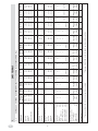 4
4
-
 5
5
-
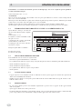 6
6
-
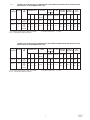 7
7
-
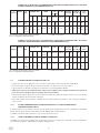 8
8
-
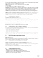 9
9
-
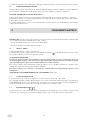 10
10
-
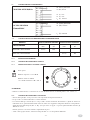 11
11
-
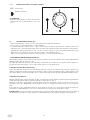 12
12
-
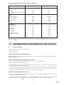 13
13
-
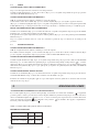 14
14
-
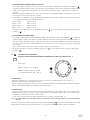 15
15
-
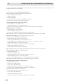 16
16
-
 17
17
-
 18
18
-
 19
19
-
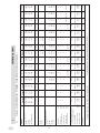 20
20
-
 21
21
-
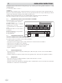 22
22
-
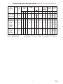 23
23
-
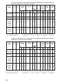 24
24
-
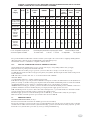 25
25
-
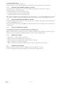 26
26
-
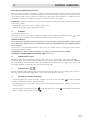 27
27
-
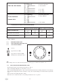 28
28
-
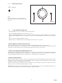 29
29
-
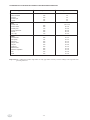 30
30
-
 31
31
-
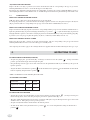 32
32
-
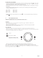 33
33
-
 34
34
-
 35
35
-
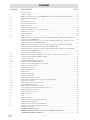 36
36
-
 37
37
-
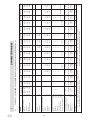 38
38
-
 39
39
-
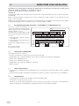 40
40
-
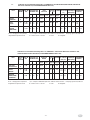 41
41
-
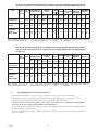 42
42
-
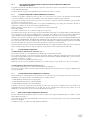 43
43
-
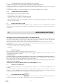 44
44
-
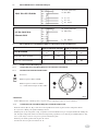 45
45
-
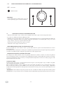 46
46
-
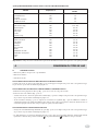 47
47
-
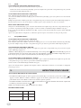 48
48
-
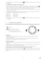 49
49
-
 50
50
-
 51
51
-
 52
52
-
 53
53
-
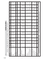 54
54
-
 55
55
-
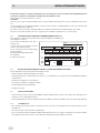 56
56
-
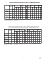 57
57
-
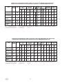 58
58
-
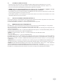 59
59
-
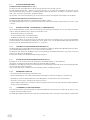 60
60
-
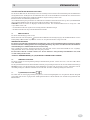 61
61
-
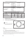 62
62
-
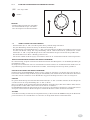 63
63
-
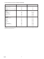 64
64
-
 65
65
-
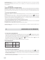 66
66
-
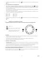 67
67
-
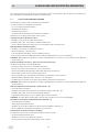 68
68
-
 69
69
-
 70
70
-
 71
71
-
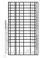 72
72
-
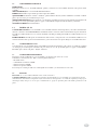 73
73
-
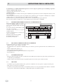 74
74
-
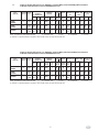 75
75
-
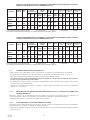 76
76
-
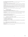 77
77
-
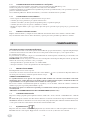 78
78
-
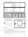 79
79
-
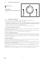 80
80
-
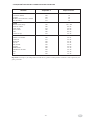 81
81
-
 82
82
-
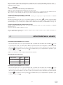 83
83
-
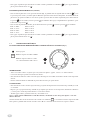 84
84
-
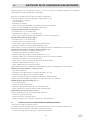 85
85
-
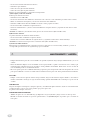 86
86
-
 87
87
-
 88
88
-
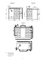 89
89
-
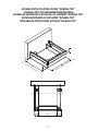 90
90
-
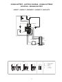 91
91
-
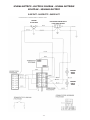 92
92
-
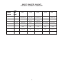 93
93
-
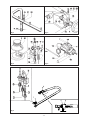 94
94
-
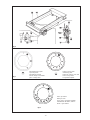 95
95
-
 96
96
-
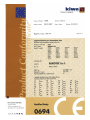 97
97


Hobart G2SSMA77 Installation, Use And Maintenance Instructions
- Tipo
- Installation, Use And Maintenance Instructions
en otros idiomas
- français: Hobart G2SSMA77
- italiano: Hobart G2SSMA77
- English: Hobart G2SSMA77
- Deutsch: Hobart G2SSMA77
Artículos relacionados
Otros documentos
-
MBM GF49T Installation, Use And Maintenance Instructions
-
Evolve E80CBG02 Instruction, Use And Maintenance Manual
-
GGM Gastro GKB879T El manual del propietario
-
REX C9540 Manual de usuario
-
Hendi 225899 Manual de usuario
-
Whirlpool CP87SG1 /HA S Guía del usuario
-
Electrolux EHG6410X Manual de usuario
-
Alfa FXSTONEMLP Especificación
-
-
Blodgett 961/961/951 El manual del propietario