Simplicity 074085-00 Manual de usuario
- Categoría
- Compresores de aire
- Tipo
- Manual de usuario
Este manual también es adecuado para

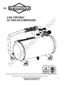
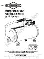
4 GAL PORTABLE
OIL FREE AIR COMPRESSOR
Product Model # 074085-00
Read and understand this operator's manual thoroughly before using the product. It contains important
information for your safety as well as operating and maintenance advice.
BRIGGS & STRATTON CORPORATION,
MILWAUKEE, WISCONSIN, U.S.A.
80028054 (Rev A)
®
Not for Reproduction

Thank you for purchasing this quality-built Briggs & Stratton
®
air compressor. We are pleased that
Briggs & Stratton
®
brand. When operated and maintained
according to the instructions in this manual, your Briggs &Stratton air compressor will provide many
years of dependable service.
You can contact Briggs & Stratton
®
Customer Service by phone at (800) 743-4115, or on the
Internet at BRIGGSandSTRATTON.COM.
Date Purchased
Not for Reproduction

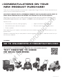
Thank you for choosing a product manufactured or supported by Briggs & Stratton. We are honored that you
chose us as your power equipment provider.
WE STRIVE TO CREATE HELPFUL, DEPENDABLE PRODUCTS THAT YOU CAN RELY ON FOR YEARS TO
COME, WHILE COUNTING ON US TO SUPPORT YOU THROUGH THE LIFE OF YOUR PRODUCT.
Registering your product is the first step towards receiving the best post-sale experience. To begin, go to
onlineproductregistration.com, text ‘register’ to 33988 or scan the code below from your mobile device.
Benefits include:
• Confirmation of warranty coverage eligibility
• More efficient parts and service support
• Product updates
• Helpful maintenance and usage tips
• Discounts and offers on future products
After registering you will receive a confirmation email that includes an invitation to rate and review your new
product online.
Whether you absolutely love your new product or have a suggestion to enhance it, we’d love to hear from you
and value your feedback.
CONGRATULATIONS ON YOUR
NEW PRODUCT PURCHASE!
TO BEGIN:
GO TO ONLINEPRODUCTREGISTRATION.COM
TEXT ‘REGISTER’ TO 33988
OR SCAN THIS CODE:
Data rates may apply
OR TO START THE REGISTRATION PROCESS ON YOUR MOBILE DEVICE:
80028054 (Rev A)
Not for Reproduction

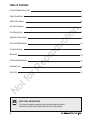
SAVE THESE INSTRUCTIONS
This manual contains important safety and operating instructions.
Read all instructions and follow them with use of this product.
Key Parts Diagram
Operation Instructions
Care And Maintenance
Troubleshooting
Warranty
Product Specifications
Exploded view
Parts List
Safety Information
Table of Contents
Product Registration Form
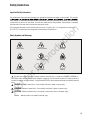
Safety Guidelines
Parts Description 8
Not for Reproduction

Flying Objects
Operator's Manual
Hot Surface
Electrical ShockToxic Fumes
Safety Guidelines
Important Safety Information
Safety Symbols and Meanings
Warning
Bursting
Hearing
Fire
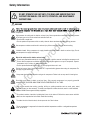
The safety alert symbol indicates a potential hazard to personal injury. A signal word (DANGER, WARNING, or
CAUTION) is used with the alert symbol to designate a degree or level of hazard seriousness. A safety symbol may
be used to represent the type of hazard. The signal word NOTICE is used to address practices not related to personal
injury.
indicates a hazard which, if not avoided, will result in death or serious injury.
indicates a hazard which, if not avoided, could result in death or serious injury.
indicates a hazard which, if not avoided, could result in minor or moderate injury.
address practices not related to personal injury.
DANGER
WARNING
CAUTION
Notice
The manufacturer cannot possibly anticipate every possible circumstance that might involve a hazard. The warnings
work method, or operating technique that the manufacturer does not specifically recommend, you must satisfy
yourself that it is safe for you and others. You must also make sure that the procedure, work method, or operating
technique that you choose does not render the compressor unsafe.
The procedures described in this manual are solely for this 4 U.S. gallon (15.1 L) air compressor at a maximum
of P=125 PSI. The device has been designed and constructed for household use.
Not for Reproduction

DO NOT OPERATE THIS UNIT UNTIL YOU READ AND UNDERSTAND THIS
INSTRUCTION MANUAL FOR SAFETY, OPERATION, AND MAINTENANCE
INSTRUCTIONS.
compressor.
Do not restrict compressor ventilation openings or place objects against or on top of compressor. Operate
compressor only in a clean, dry, well ventilated area.
Do not operate unattended. Always turn off and unplug unit when not in use.
High pressure air could result in death or serious injury. Never operate above maximum operating pressure
of the spray gun or tool. Drain water from tank after each use.
Do not weld or repair tank.
Do not spray flammable materials in vicinity of any flame or ignition sources including the compressor unit.
Risk of fire could result in death or serious injury.
Do not operate with pressure switch or safety valve set above maximum allowable working pressure.
Hot compressor surfaces could result in serious injury. Allow compressor to cool before touching.
Inhalation hazard. Using compressor to supply breathing air could result in death or serious injury. Do not
use compressor to supply breathing air.
Risk of serious eye injury. Always wear ANSI Z87.1 approved safety glasses when using air compressor. Do
not spray any part of the body.
Safety Information
WARNING
Shock risk could result in death or serious injury. Only connect compressor to a properly grounded
receptacle. KEEP CHILDREN AWAY FROM THE AIR COMPRESSOR AT ALL TIMES.
Always wear hearing protection when using an air compressor. Failure to do so may result in hearing loss.
Dust can be created when cutting, sanding, drilling or grinding materials such as wood, paint, metal,
concrete, cement, or other masonry. To reduce your exposure to these chemicals, work in a well ventilated
area and ALWAYS wear approved safety equipment.
This product contains chemicals, including lead, know to the state of California to cause cancer and birth
defects or other reproductive harm.
To reduce the risk of electric shock, do not expose to rain. Store indoors.
This air compressor is supposed to be stored in ambient temperature condition : centigrade temperature
from -20 to +40ºC.
Wash hands after handling.
Not for Reproduction

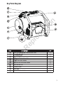
Key Parts Diagram
AIR TANK BALL VALVE
AIR LINE OUTLET 1
ELECTRIC MOTOR AIR COMPRESSOR PUMP
POWER SWITCH
SAFETY VALVE
AIR PRESSURE REGULATOR
REGULATED PRESSURE GAUGE
B
POWER CORD
TANK PRESSURE GAUGE
AIR TANK
Not for Reproduction

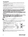
H. POWER CORD:
G
This compressor should be used on a nominal 120 V grounded circuit Use a power
cord that is equipped with a grounding plug. Verify that the compressor is plugged into an outlet that
has the same configuration as the plug. Do not use an adapter with this compressor.
Grounding pin
Plug
Grounded
outlets
I. AIR TANK: The tank is where the compressed air is stored.
J. AIR TANK BALL VALVE: The ball valve is used to
remove moisture from the air tank after the compressor
is shut off.
A. ELECTRIC MOTOR:
AIR COMPRESSOR PUMP:
B. POWER SWITCH:
C
D
E
F
The switch turns the compressor on and off. It is operated manually and when it is
in the I (on) position, it allows the motor to start if the pressure in the air tank is below the factory
set cut-in pressure, and allows the motor to stop if the pressure in the air tank reaches the factory set
cut-out pressure. Be sure to set this switch to the O (off) position when the compressor is not being
used and before unplugging the compressor.
WARNING:Never exceed the maximum working pressure of the tool.
WARNING
REGULATED
LINE
The motor is used to power the pump. It is equipped with at thermal overtoad
pfotector.If the motor overheats for any reason, the thermal overload protector will shut it down in
order to prevt the motor from being damaged.
The pump compresses the air and discharges it into the tank via the
piston that moves up and down in the cylinder.
Check with a licensed electrician if the grounding
instructions are not understood or there is doubt as to
whether the product is properly grounded. Do not modify
the plug provided. If it will not fit the outlet, have the
proper outlet installed by a licensed electrician.
DANGER
Improper installation of the grounding plug will result in a risk of electric shock. If repair or
replacement of the cord or plug is necessary, do not connect the grounding wire to either flat
blade terminal. The grounding wire is in the green outer surface.
Never attempt to open the drain valve when the tank pressure is more than 10 PSI.
Parts Description
The outlet is connected to the air hose with quick connector.
Not for Reproduction

Breaking-in the pump
1. Set the power switch (B) to the 0 (off) position.
3. Turn the air pressure regulator knob counter-clockwise until it stops.
5. Set the power switch (B) to the I
(on) position. The compressor will start. Run the compressor
for 30 minutes. If it fails, turn it off immediately and call the toll-free helpline at (800) 743-4115.
4. Plug in the power cord (H).
6. After 30 mintes, set the power switch (B) to the 0 (off) position.
7. Close the tank drain valve (J) by turning it clockwise.
8. Set the power switch (B) to the I
(on) position. The air tank will fill to “cut-out’’ pressure and then
the compressor's motor will stop. The compressor is now ready for use.
NOTES:
During the initial break-in cycle, a slight smell from the motor brushes seat might be
present. This is normal for universal motors and should stop after a short moment.
2. Open the tank drain valve (J) by turning it counter clockwise to permit the air to escape and
prevent air pressure build up in the air tank during the break-in period.
Operation Instructions
Not for Reproduction

Before each start-up
How to start
How to shut down
1. Set the power switch (B) to the 0
(off) position.
2. Turn the air pressure regulator knob (D) counter-clockwise until it stops.
3. Attach air hose/accessories or air tools.
1. Close the tank drain valve (J).
2. Plug in the power cord (H).
3. Set the power switch (B) to the I
(on) position and allow tank pressure to build. Motor will stop
when tank pressure reaches "cut-out" pressure.
4. Turn the air pressure regulator knob (D) clockwise until desired pressure is reached.
5. The compressor is ready for use.
1. Set the power switch (B) to the 0
(off) position.
2. Unplug the power cord (H).
3. Reduce the pressure in the tank through the outlet hose.
Pulling the safety valve ring (C) and keeping
it open will also reduce the pressure in the tank.
WARNING! Too much air pressure causes a hazardous risk of bursting. Check the
manufacturer's maximum pressure rating for air tools and accessories. The regulator outlet pressure must
never exceed the maximum pressure rating.
If the pump has been transported or turned upside down (even partially), allow
the pump to sit in a normal, upright position for approximately 10 minutes before starting.
High temperatures are generated by the electiic motor and the pump.
To prevent bums or other injuries, DO NOT touch the air compressor while it is running.
Allow it to cool before handling or servicing. Keep children away from the air compressor at all times.
CAUTION!
Escaping air and moisture can propel debris that may cause eye injury. Wear safety
goggles when opening the drain valve.
WARNING!
To avoid personal injuny, always shut off and unplug the unit, and relieve all air
relieve all air pressure from the system before performing any service on the air compressor.
Operating Instructions
WARNING
Risk of bursting.
Risk of unsafe operation. Unit cycles automatically when power is on. When
performing maintenance, you may be exposed to voltage sources, compressed air or moving
parts. Personal injuries can occur. Before performing any maintenance or repair, disconnect
power source from the compressor and bleed off all air pressure.
Not for Reproduction

performing.
OPEN
CLOSE
Care and Maintenance
Not for Reproduction

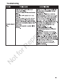
PROBLEM POSSIBLE CAUSE
CORRECTIVE ACTION
There is low
pressure, not
enough air, or the
compressor does
not stop.
1. The tank ball valve is open.
2. There is a leak in the fittings.
3. There is a prolonged or excessive use
of air.
4. The compressor is not large enough.
5. There is a hole in the air hose.
6. The tank leaks.
7. The seals are blown.
8. The valve leaks.
9. There is a leaking or worn piston.
1. Close the ball valve.
2. Check fittings with soapy water. Tighten
or reseal leaking fittings. DO NOT
OVERTINGHTRN.
3. Decrease the amount of air used.
4. Check the air requirement of the
accessory. If it is higher than the CFM and
the pressure supplied by the compressor,
you need a larger compressor. Most
accessories are rated at 25% of the actual
CFM while running continuously.
5. Check and replace if necessary.
WARNING
6. Immediately replace the
tank. DO NOT attempt to repair.
7. Replace the compressor assembly.
8. Replace the compressor assembly.
9. Replace the compressor assembly.
Air leaks from the
regulator or the
regulator does not
regulate air
pressure.
1. The internal parts of the
regulator are dirty or
damaged.
1. Replace the regulator or
internal parts.
The regulated
pressure gauge
reading drops
when the air
accessory is
being used.
1. This is normal.
2. The compressor is not
large enough.
1. If the pressure drops too low, adjust the
regulartor while the accessory is used.
2. Check the air requirement of the
accessory. If it is higher than the CFM and
the pressure supplied by the compressure
supplied by the compressor, you need a
larger compressor. Most accessories are
rated at 25% of the actual CFM while
running continuously.
The pressure
relief valve
opens.
1. The tank pressure exceeds the normal
rating pressure.
2. The pressure switch is stuck.
1. Replace the pressure switch.
2. Replace the pressure switch.
Troubleshooting
Not for Reproduction

Troubleshooting
Not for Reproduction

Briggs & Stratton Air Compressor Warranty Policy
This Limited warranty does not include the following:
LIMITED WARRANTY
A. Parts that are worn or broken or which have become inoperative due to abuse, misuse, accidental damage, neglect or lack of
proper installation, operation or maintenance (as outlined in the applicable owner’s manual or operating instructions) or product
that has been used for industrial, professional, commercial or rental purposes;
B. Normal wear and tear or expendable parts or accessories that may be supplied with the product which are expected to become
inoperative or unusable after a reasonable period of use;
C. Routine maintenance and consumable items such as, but not limited to fuel, lubricants, valves, belts, knobs, nuts, fluids,
tune-ups, or adjustments;
D. Damage caused by repairs made or attempted by persons not authorized by the manufacturer;
E. Product that was sold to the original purchaser as reconditioned or refurbished product (unless otherwise specified in writing);
F. Product or parts thereof if any part from another manufacturer has been installed or any repairs or alterations have been made
or attempted by unauthorized persons;
G. Normal deterioration of the exterior finish such as, but not limited to, scratches, dents, paint chips, nor any corrosion or
discoloring by heat, abrasive and chemical cleaners;
H. Component parts sold by and identified as the product of another company, which shall be covered under the other product
manufacturer’s warranty, if any.
October, 2015
These are our standard warranty terms, but occasionally there may be additional warranty coverage that was not determined at
time of publication. For a listing of current warranty terms for your air compressor, go to BRIGGSandSTRATTON.COM
BRIGGS & STRATTON is a trademark of BRIGGS & STRATTON CORPORATION and is used under license to Alton Industry
Co. Ltd®. Alton Industry Co. Ltd warrants this Briggs & Stratton brand product for a period of one year from the date of
original retail purchase against defects in materials and workmanship. Subject to the conditions and limitations described
below, if Alton Industry Co. Ltd determines this product is covered under this warranty, it will be replaced with the same
model or one of equal value or specification, at Alton Industry Co. Ltd’s option. Alton Industry Co. Ltd will bear the cost of
replacement. The purchaser must contact Alton Industry Co. Ltd® for all warranty authorizations.
There is no other express warranty. Implied warranties, including those of merchantability and fitness for a particular
purpose, are limited to one year, or to the extent permitted by law. Liability for incidental or consequential damages are
excluded to the extent exclusion is permitted by law. Some states or countries do not allow limitations on how long an
implied warrant lasts, and some states of countries do not allow the exclusion or limitation of incidental or consequential
damages, so the above limitation and exclusion may not apply to you. This warranty gives you specific legal rights and you
may also have other rights which vary from state to state or country to country.
Save your proof of purchase receipt. If you do not provide proof of the initial purchase date at the time warranty service is
requested, the manufacturing date of the product will be used to determine the warranty period. Product registration is not
required to obtain warranty service on Briggs & Stratton products.
®
®
For questions about our warranty on this product, contact us at:
Alton Industry LTD. Group
1031 North Raddant Road
Batavia Illinois 60510
888-899-0146
info@altonindustries.com
www.altonindustries.com
Not for Reproduction

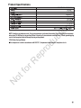
074085-00 / 0100441
Oil-less
1/2 HP
120/4/60
4 Gallon
95 PSI
125 PSI
8
2.1
*
1.1
*
NOTE: Avoid use of extension cords. If use of an extension cord cannot be avoided, the cord should be a minimum
wire size of 12 AWG and no longer than 30 feet. Use only a 3-wire extension cord that has a 3-blade grounding plug
and a 3-slot receptacle that will accept the plug on the product.
*CFM: Cubic Feet per Minute.
This compressor is rated in accordance with ISO 1217, displacement compressors acceptance tests.
Product Specifications
Not for Reproduction

Exploded View
Not for Reproduction

Adaptor fitting
Spring
Check valve End Cap
1
21
2
3
4
5
6
7
8
9
10
16
17
18
19
20
21
22
23
24
25
26
27
28
11
12
13
14
1
1
2
1
1
1
6
1
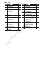
Handgrip
Tank
Pressure Gauge
Quick Coupler
Pressure Regulator
Safety Valve
Drain Valve
End Cap
Bolt M6 X 12
Rubber Foot
Motor Pump Assembly
Cushion Pad I
1
2
4
4
2
29
Cushion Pad II
1
1
1
1
1
2
1
1
2
2
2
Metal Tube
Screw M3x6
PCB
Retaining Plate
Shroud
Bolt M6 X 16
Power switch
Pressure Switch
Screw M5x10
Lock Washer Ø5
Screw M4x12
15
1Clamp
Power Cord
Parts List
Not for Reproduction

®
15,1
Product Model # 074085-00
80028054 (Rev A)
Not for Reproduction

®
®
®
Not for Reproduction

Merci d’avoir choisi un produit fabriqué ou soutenu par Briggs & Stratton. C’est pour nous un honneur que vous nous
ayez choisis à titre de fournisseur d’équipement électrique.
NOUS NOUS EFFORÇONS DE CRÉER DES PRODUITS UTILES ET FIABLES SUR LESQUELS VOUS POUVEZ
COMPTER DURANT PLUSIEURS ANNÉES, TOUT EN POUVANT COMPTER SUR NOUS POUR VOUS OFFRIR DU
SOUTIEN DURANT TOUTE LA DURÉE DE VIE DE VOTRE PRODUIT.
L’enregistrement de votre produit est la première étape à suivre en vue de profiter d’une excellente expérience après-
vente. Pour commencer, visitez le onlineproductregistration.com, texte ‘register’ pour 33988 ou balayez le code ci-
dessous avec votre appareil mobile.
• Confirmation de l’admissibilité à la couverture
de la garantie
• Soutien plus efficace en matière de pièces
et de service
• Mises à jour sur les produits
• Conseils utiles sur l’entretien et l’utilisation
• Rabais et offres sur les futurs produits
Après vous être enregistré, vous recevrez un courriel de confirmation incluant une invitation
à coter et à commenter votre nouveau produit en ligne.
Que vous adoriez votre nouveau produit ou que vous ayez une suggestion en vue de l’améliorer,
nous serions heureux
de recevoir de vos nouvelles, car vos commentaires nous importent.
POUR COMMENCER, VISITEZ LE ONLINEPRODUCTREGISTRATION.COM,
TEXTE ‘REGISTER’ POUR 33988 OU BALAYEZ CE CODE pour lancer le processus
d’enregistrement sur votre appareil mobile. Des frais de données s’appliquent.
FÉLICITATIONS POUR L’ACHAT
DE VOTRE NOUVEAU PRODUIT!
Gracias por elegir un producto fabricado o respaldado por Briggs & Stratton. Estamos honrados de que nos escoja
como su proveedor de equipos de energía.
NOS ESFORZAMOS POR CREAR PRODUCTOS DE UTILIDAD Y CONFIABLES EN LOS CUALES PUEDA
DEPENDER DURANTE MUCHOS AÑOS, AL MISMO TIEMPO DE PODER SEGUIR APOYÁNDOLO A LO
LARGO DE LA VIDA ÚTIL DE SU PRODUCTO.
Registrar su producto es el primer paso hacia recibir la mejor experiencia
post-venta. Para comenzar, visite
onlineproductregistration.com, texto ‘register’ para 33988 o escanee el código a continuación de su dispositivo móvil.
Los beneficios incluyen:
• Confirmación de garantía de elegibilidad
de cobertura
• Partes más eficientes y apoyo de servicio
• Actualizaciones de productos
• Mantenimiento útiles y consejos sobre utilización
• Descuentos y ofertas sobre futuros productos
Después del registro usted recibirá un correo electrónico de confirmació
n que incluye una invitación para calificar y
comentar su nuevo producto en línea.
Nos encantaría saber de usted y valoramos sus comentarios, independientemente de que le
encante su nuevo producto o tenga sugerencias para mejorarlo.
PARA COMENZAR, VISITE ONLINEPRODUCTREGISTRATION.COM,
TEXTO ‘REGISTER’ PARA 33988 O ESCANEE ESTE CÓDIGO
para comenzar con el proceso de registro en su dispositivo móvil. Aplica tarifas de datos.
¡FELICITACIONES POR LA
COMPRA DE SU NUEVO PRODUCTO!
80028054 (Rev B)
Not for Reproduction

INSTRUCCIONES DE MONTAJE
CLAVE DIAGRAMA DE PIEZAS
.......................................................................
..............................................................................................
............................................................................................
........................
..........................................................................
3
5
..............................................................................................
....................................................................................................
.............................................................................................................................
........................................................................................
................................................................................................................
..................................................................................................................
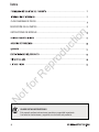
GUARDE ESTAS INSTRUCCIONES
Este manual contiene instrucciones operativas y seguridad importante.
Lea todas las instrucciones y seguirlas con el uso de este producto.
DESCRIPCIÓN DE LAS PARTES.............................................................................................
8
Índice
Not for Reproduction

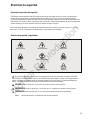
El vuelo se opone
Manual del operador
Superficie caliente
Choque eléctricoVapores toxicos
Directrices de seguridad
Información importante de seguridad
Símbolos de seguridad y significados
El fabricante no puede anticipar todas las posibles circunstancias que puedan implicar un riesgo. Las advertencias
de este manual y las etiquetas y calcomanías adheridas a la unidad, por lo tanto, no todos los servicios incluidos.
Si utiliza un procedimiento, método de trabajo o técnica de operación que el fabricante no recomienda específicamente,
debe satisfacer a ti mismo de que es seguro para usted y los demás. También debe asegurarse de que el procedimiento,
método de trabajo o técnica de operación que elija no haga al compresor inseguro.
Advertencia
Muy llenoFuego
El símbolo de alerta de seguridad indica un riesgo potencial de lesiones personales. Una palabra (PELIGRO,
ADVERTENCIA o PRECAUCIÓN) se utiliza con el símbolo de alerta para designar un grado o nivel de gravedad del
riesgo. Un símbolo de seguridad puede ser usado para representar el tipo de peligro. La palabra de señalización
AVISO \ s utilizado para prácticas de dirección no relacionados con lesiones personales.
indica un peligro que, si no se evita, provocará la muerte o lesiones graves.
indica un peligro que, si no se evita, vaca / t / resultado en la muerte o lesiones graves.
indica un peligro que, si no se evita, podría causar lesiones leves o moderadas.
prácticas de dirección no relacionados con lesiones personales.
PELIGRO
ADVERTENCIA
PRECAUCIÓN
aviso
Audición
Los procedimientos descritos en este manual son únicamente para este compresor de aire de 4 galones (15,1 L) a un
máximo de P = 125 PSI. El dispositivo ha sido diseñado y construido para uso doméstico.
Not for Reproduction

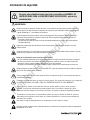
No opere esta unidad hasta que haya leído y entendido este MANUAL DE
INSTRUCCIONES PARA LAS INSTRUCCIONES DE SEGURIDAD, operación y
mantenimiento.
Información de seguridad
ADVERTENCIA
Riesgo de incendio causado por chispas del motor y el interruptor de presión podría ocasionar la muerte o
lesiones graves. No haga funcionar el compresor cerca de gas o vapor inflamable. Nunca almacene líquidos
o gases inflamables en * proximidades de compresor.
Superficies compresores calientes podrían causar lesiones graves. Permita que el compresor se enfríe
antes de tocarlo.
Peligro de inhalación. El uso del compresor para suministrar aire respirable puede causar la muerte o lesiones
graves. No hay compresor de uso para suministrar aire respirable.
Riesgo de lesiones oculares graves. Siempre use ANSI Z87.1 gafas de protección cuando se utiliza el compresor
de aire. No rocíe cualquier parte del cuerpo.
Riesgo de choque podría causar la muerte o lesiones graves. Sólo conecte el compresor a un receptáculo
de tierra. MANTENGA A LOS NIÑOS LEJOS DEL COMPRESOR DE AIRE EN TODO MOMENTO.
Siempre use protección para los oídos cuando se utiliza un compresor de aire. El no hacerlo puede resultar en
la pérdida de la audición.
De aire de alta presión podría causar la muerte o lesiones graves. Nunca opere por encima de la presión
máxima de funcionamiento de la pistola o herramienta. Drene el agua del tanque después de cada uso.
No opere con interruptor de presión o válvula de seguridad establecido por encima de la presión máxima
de trabajo permitida.
No soldar o tanque reparación.
No restrinja los orificios de ventilación del compresor o colocar objetos en contra o en la parte superior del
compresor. Opere el compresor sólo en un área limpia, seca y bien ventilada.
No ponga en funcionamiento sin vigilancia. Siempre apague y desenchufe la unidad cuando no esté en uso.
No rocíe materiales inflamables en las proximidades de nada con fuego o de ignición, incluyendo el compresor.
Riesgo de incendio podría causar la muerte o lesiones graves.
Cuando corta lija, taladra o pule materiales como por ejemplo madera, pintura, metal, hormigón,
cemento, u otro tipo de mampostería se puede producir polvo. Para reducir la exposición a estas
sustancias químicas, trabaje en un área bien ventilada y use siempre el equipo de seguridad aprobado.
Este producto contiene plomo y componentes de plomo que, según el Estado de California, provocan
malformaciones congénitas y ostros danos en el sistema reproductivo. Lávese las manos después de
manipular este producto.
Para reducir el riesgo de descarga eléctrica, no la exponga a la lluvia. Tienda en el interior.
Se supone que este compresor de aire debe almacenarse en condiciones de temperatura ambiente: temperatura
centígrada de -20 a + 40ºC.
Not for Reproduction

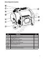
Clave diagrama de piezas
TANQUE DE AIRE VALVULA DE BOLA
LÍNEA DE SALIDA DE AIRE
1
MOTOR ELECTRICO Y AIRE BOMBA DEL COMPRESOR
INTERRUPTOR DE ALIMENTACIÓN
VÁLVULA DE SEGURIDAD
AIRE REGULADOR DE PRESIÓN
MEDIDOR DE PRESIÓN REGULADA
B
CABLE ELÉCTRICO
MANÓMETRO DEL TANQUE
TANQUE DE AIRE
Not for Reproduction

H. CABLE ELÉCTRICO: Este compresor debe utilizarse en un circuito de 120 V a tierra nominal Utilice
una fuente espinal que está equipado con un enchufe de conexión a tierra. Verifique que el compresor
está conectado a una toma de corriente que tiene la misma configuración que el enchufe. No utilice un
adaptador con este compresor.
pin a tierra
Enchufe
Conectado
a tierra
puntos de
venta
I. TANQUE DE AIRE: El tanque es donde se almacena el aire comprimido.
J. TANQUE DE AIRE VALVULA DE BOLA: La válvula de
bola se utiliza para eliminar la humedad del tanque de
aire después del compresor se apagará.
A. MOTOR ELÉCTRICO:
D.AIR REGULADOR DE PRESIÓN:
C.VÁLVULA DE SEGURIDAD:
BOMBA DE AIRE COMPRESOR:
B. INTERRUPTOR DE ALIMENTACIÓN: El interruptor enciende el compresor encendido y apagado. Es
operado manualmente y cuando es en la posición I (encendido), permite que el motor arranque si la
presión en el tanque de aire está por debajo de la fábrica conjunto corte-en la presión, y permite que el
motor se detenga si la presión en el tanque de aire alcanza el ajuste de fábrica cut-out presión. Asegúrese
de ajustar este interruptor en la posición O (apagado) cuando el compresor no está siendoutilizado y antes
de desconectar el compresor.
ADVERTENCIA:
E.MANÓMETRO DEL TANQUE:
Nunca exceda la presión máxima de trabajo de la herramienta.
ADVERTENCIA:
F.MEDIDOR DE PRESIÓN REGULADA:
El motor se utiliza para alimentar la bomba. Está equipado con al overtoad térmica
pfotector.If el motor se sobrecalienta por cualquier razón, el protector de sobrecarga térmica apagarlo en
ordenar a prevt el motor se dañe.
El medidor mide el nivel de presión del aire que se almacena en el tanque.
No se puede ajustar por el operador y no indica la presión dentro de la línea.
La bomba comprime el aire y lo descarga en el tanque a través de la
pistón que se mueve arriba y abajo en el cilindro.
El regulador se utiliza para ajustar la presión dentro de la línea a la
herramienta que se utiliza. Gire el mando en sentido horario para aumentar la presión y en sentido
antihorario para disminuir la presión.
Esta válvula se usa para prevenir fallo del sistema mediante el drenaje de
la presión del sistema cuando alcanza un nivel predeterminado si el interruptor de presión no ha cerrado
la motor. Itwill estallar abierto automáticamente, o puede ser activado manualmente tirando el anillo en
la válvula.
Consulte con un electricista autorizado si la puesta a
tierra instrucciones no se entienden o hay duda en
cuanto a si el producto está correctamente conectado
a tierra. No modifiqueel enchufe proporcionado. Si no
va a encajar en el tomacorriente, la instale el
tomacorriente adecuado por un electricista autorizado.
PELIGRO
La instalación incorrecta del enchufe a tierra dará lugar a un riesgo de descarga eléctrica. Si la
reparación o reemplazar el cable o el enchufe es necesario, no conecte el cable de tierra a cualquiera
planas terminal de hoja. El cable de tierra se encuentra en la superficie exterior de color verde.
Nunca intente abrir la válvula de drenaje cuando la presión del tanque es de más de 10 PSI.
El indicador mide la presión de salida regulada.
G.LÍNEA DE SALIDA DE AIRE: La salida está conectada a la manguera de aire con el conector rápido.
Descripción De Las Partes
Not for Reproduction

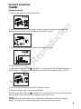
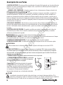
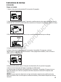
Romper-en la bomba
PREPARACIÓN
1. Ajuste el interruptor de alimentación (B) a la posición 0 (apagado).
3. Gire la perilla del regulador de presión de aire en sentido antihorario hasta que se detenga.
5. Ajuste el interruptor de alimentación (B) a la posición I (encendido). El compresor se iniciará.
Haga funcionar el compresor durante 30 minutos. Si falla, apáguelo de inmediato y llame a la línea de
ayuda gratuita al (800) 743-4115.
4. Conecte el cable de alimentación (H).
6. Después de 30 minutos, ajuste el interruptor de alimentación (B) a la posición 0 (apagado).
7. Cierre la válvula de drenaje del tanque (J) girando en sentido horario.
8. Conjunto aunque el interruptor de alimentación (B) a la posición I (encendido). El tanque de aire se
llenará de presión para "cortar-ouf y después motor del compresor se detendrá. El compresor está
listo para su uso.
NOTAS:
Durante el ciclo de rodaje inicial, un ligero olor desde el asiento de las escobillas del motor
podría ser presente. Esto es normal para los motores universales y debe detenerse después de un breve
momento.
2. Abra la válvula de drenaje del tanque (J) girando en sentido contrario a las agujas del reloj para permitir
la salida del aire e prevenir la presión del aire se acumulan en el tanque de aire durante el período de rodaje.
Instrucciones de montaje
CERRAR
O
(apagado)
(en)
ABRIR
Not for Reproduction

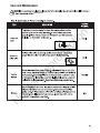
Antes de cada puesta en marcha
Cómo empezar
1. Ajuste el interruptor de alimentación (B) a la posición 0 (apagado).
2. Gire la perilla del regulador de presión de aire (D) en sentido antihorario hasta que se detenga.
3. Coloque aire manguera / accesorios o herramientas de aire.
1. Cierre la válvula de drenaje del tanque (J).
2. Conecte el cable de alimentación (H).
3. Ajuste el interruptor de alimentación (B) en la que (a) posición y permitir que la presión del tanque
construir. El motor se detendracuando la presión del tanque alcanza "corte" de presión.
4. Gire la perilla del regulador de presión de aire (D) en sentido horario hasta que se alcanza la presión
deseada.
5. El compresor está listo para su uso.
How to shut down
1. Ajuste el interruptor de alimentación (B) a la posición 0 (apagado).
2. Desconecte el cable de alimentación (H).
3. Reducir la presión en el tanque a través de la manguera de salida.
Tirando del anillo de la válvula de seguridad (C) y mantener
abierta también reducirá la presión en el tanque.
¡ADVERTENCIA! Too much air pressure causes a hazardous risk of bursting.
Check the manufacturer's maximum pressure rating for air tools and accessories. The regulator outlet
pressure must never exceed the maximum pressure rating.
Si la bomba se ha transportado o al revés (aunque sea parcialmente), permitirá la bomba que se siente
en una posición normal, en posición vertical durante aproximadamente 10 minutos antes de comenzar.
Las altas temperaturas son generados por el motor eléctrico y la bomba.
Para evitar quemaduras u otras lesiones, NO toque el compresor de aire mientras se está ejecutando.
Deje que se enfríe antes de manipular o dar servicio. Mantenga a los niños alejados del compresor de aire
en todo momento.
¡PRECAUCIÓN!
Aire que se escapa y la humedad pueden lanzar fragmentos que pueden causar lesiones en los ojos.
Use la seguridad gafas cuando se abre la válvula de drenaje.
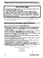
¡ADVERTENCIA!
Para evitar lesiones personales, siempre apague y desenchufe la unidad, y aliviar todo el aire
aliviar toda la presión de aire del sistema antes de realizar cualquier servicio en el compresor de aire.
Instrucciones de operación
¡ADVERTENCIA!
Riesgo de explosión.
Riesgo de operación insegura. Ciclos de unidad automáticamente cuando la alimentación está encendida.
Cuando realizar el mantenimiento, usted puede estar expuesto a fuentes de voltaje, aire comprimido o
en movimiento partes. Pueden ocurrir lesiones personales. Antes de realizar cualquier operación de
mantenimiento o reparación, desconecte fuente de alimentación del compresor y purgue toda la presión
de aire.
Not for Reproduction

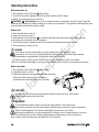
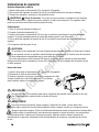
Cuidado y Mantenimento
Para evitar que se oxide el interior del tanque, la condensación se
debe drenar al final de cada día de trabajo. Asegurese de usar gafas
protectoras. Libere la presión de aire en el sistema y luego abra la
valvula de drenaje en la parte inferior del tanque.
Drene el
tanque
A diario
A diario
N/C
N/C
Revise la
válvula de
descarga
Verifique que
no haya fugas
Almacenaje
Jale el anillo de la válvula de descarga de presión diariamente para
asegurarse de que la válvula funcione de manera adecuada y para
eliminar obstrucciones.
CVerifique que todas las conexiones estén apretadas. Una pequeña
fuga en cualquier pieza (el tanque, mangueras, conexiones de tuberías
o tubos de transferencia) reducirá el rendimiento de la unidad. Utilice
una botella con rociador para rociar una pequeña cantidad de agua
jabonosa alrededor del área donde habría una fuga. Si aparecen
burbujas, repare y reemplace el componente defectuoso. No apriete
demasiado las conexiones.
Antes de almacenar la unidad por un periodo prolongado, use una
pistola de aire para eliminar todo el polvo y los desechos del
compresor. Desconecte y enrolle el cable eléctrico. Jale la válvula
de descarga de presión para liberar toda la presión del tanque. Drene
toda la humedad del tanque. Cubra toda la unidad para protegerla del
polvo y la humedad.
Not for Reproduction

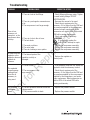
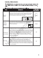
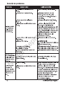
Solución de problemas
Not for Reproduction

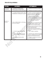
La válvula de
descarga de
presión se abre
1. La presión del tanque excede
la clasificación de presión normal.
2. El interruptor de presión está atascado.
1. Reemplace el interruptor de presión.
2. Reemplace el interruptor de presión.
El motor no
funciona
1. La presión del tanque excede el límite
preestablecido del interruptor de presión.
2. Hay un fusible fundido o el interruptor
de circuito se disparó.
3. La válvula de control está atascada
y abierta.
4. El cable es de un calibre incorrecto
o la extensión eléctrica es demasiado
larga
5. Las conexiones eléctricas están
sueltas.
1. El motor arrancará automáticamente
cuando la presión del tanque esté por
debajo de la presión de activación.
2. Reemplace el fusible fundido o
restablezca el interruptor de circuito. No
use el fusible ni el interruptor de circuito
con una clasificación más alta que la
especificada para su circuito de
derivación.
Verifique que usa el fusible adecuado;
se acepta el fusible “Fusetron”, tipo T.
Revise si hay una baja de voltaje y
asegúrese de que la extensión eléctrica
sea del tamaño adecuado.
Desconecte otras aplicaciones del
circuito. Use el compresor en un circuito
separado.
3. Retire y limpie o reemplace.
4. Compruebe que el cable sea del calibre
correcto y asegúrese de que la extensión
eléctrica sea del tamaño adecuado.
5. Póngase en contacto con un centro
de servicio autorizado.
Solución de problemas
Not for Reproduction

Briggs & Stratton Política de garantía del compresor de aire
Octubre, 2015
Estos son nuestros términos de garantía estándar, pero en ocasiones puede haber cobertura de la garantía adicional que no fue
determinado en el momento de su publicación. Para obtener una lista de los términos de garantía actuales para su compresor
de aire, vaya a BRIGGSandSTRATTON.COM
TM
Para preguntas acerca de nuestra garantía sobre este producto, póngase en contacto con nosotros en:
Alton Industria LTD. Grupo 1031 Norte Raddant Road
Batavia Illinois 60510
888-899-0146
info@altonindustries.com
www.altonindustries.com
Not for Reproduction

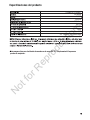
074085-00 / 0100441
120/4/60
Sin aceite
1/2 HP
95 PSI
125 PSI
SJT 18 AWG / 1,83 m de largo
15,1 litros
0,05
0,03
Este compresor tiene una clasificación de acuerdo con la norma IOS 1217,desplazamiento Compresores
pruebas de aceptación .
Especificaciones del producto
Not for Reproduction

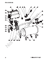
Vista detallada
Not for Reproduction

Adaptador de conexión
Tapa de cierre
Primavera
1
2
3
4
5
6
7
8
9
10
16
17
18
19
20
21
22
23
24
25
26
27
28
29
11
12
13
14
15
Empuñadura
Tanque
Manómetro
Acoplamiento rápido
Regulador de presión
Válvula de seguridad
Válvula de drenaje
Tapa final
Perno M6 X 12
Pie de goma
Conjunto de bomba de motor
Almohadilla de cojín I
Almohadilla de cojín II
Tubo metálico
Atornillar M3x6
PCB
Placa de retención
Sudario
Perno M6 X 16
Interruptor de alimentación
Interruptor de presión
Tornillo M5x10
Lock Washer Ø5
Tornillo M4x12
Abrazadera
Cable de alimentación
Lista de piezas
PIEZA DESCRIPTI N CANT. PIEZA DESCRIPTI N CANT.
1
2
1
1
2
1
1
1
6
1
2
2
2
1
1
2
4
4
2
1
1
1
1
1
2
1
1
Not for Reproduction
-
 1
1
-
 2
2
-
 3
3
-
 4
4
-
 5
5
-
 6
6
-
 7
7
-
 8
8
-
 9
9
-
 10
10
-
 11
11
-
 12
12
-
 13
13
-
 14
14
-
 15
15
-
 16
16
-
 17
17
-
 18
18
-
 19
19
-
 20
20
-
 21
21
-
 22
22
-
 23
23
-
 24
24
-
 25
25
-
 26
26
-
 27
27
-
 28
28
-
 29
29
-
 30
30
-
 31
31
-
 32
32
-
 33
33
-
 34
34


Simplicity 074085-00 Manual de usuario
- Categoría
- Compresores de aire
- Tipo
- Manual de usuario
- Este manual también es adecuado para
en otros idiomas
- English: Simplicity 074085-00 User manual
Artículos relacionados
-
Simplicity 074080-00 Manual de usuario
-
-
-
-
-
-
Simplicity 074065-00 Manual de usuario
-
-
-