
PS Series
PS8 – LS400 – PS8 Analogue TD Controller
PS10R2 –LS600 -PS10 Analogue TD Controller
PS15R2 – PS15 Analogue TD Controller
User Manual
PS Series User Manual V1.01
Date: 08/09/2009

Page 2/82 INTRODUCTION
PLEASE READ CAREFULLY BEFORE PROCEEDING
BASIC PRECAUTIONS
Do not open the speaker system or attempt to disassemble the internal parts or modify them in any
way. The speaker system contains no user-serviceable parts. If it should appear to be malfunctioning
or damaged, discontinue use immediately and have it inspected by qualified NEXO service personnel.
Water exposure: Do not expose the speaker system to direct rain, do not use it near water or in wet
conditions. Do not place containers with liquid on speaker system as they might spill into openings. If
any liquid such as water seeps into the speaker system, have it inspected by qualified NEXO
personnel.
SYSTEM DEPLOYMENT SAFETY RULES
Read User Manual before deployment. Before use of enclosed speaker system,
please ensure that anyone involved in system deployment understands the rigging –
stacking – pole mounting safety rules as described in the speaker system User Manual.
Failure to do this exposes people to potential injury or death.
Always consult qualified NEXO personnel if the device installation requires construction work and make
sure to observe the following precautions:
Mounting precautions
- choose mounting hardware and an installation location that can support the weight of the speaker
system;
- do not use speaker system handles for suspended installation;
- do not expose speaker system to excessive dust or vibration, or extreme cold or heat to prevent
possibility of component damage;
- do not place the speaker system in an unstable position from which it might fall accidentally;
- if speaker systems uses a stand, ensure that stand specifications are adapted, and that stand
height does not exceed 1.40m/55”; never move the stand while the speaker is in position.
Connection and powering precautions
- remove all connected cables before moving the speaker system;
- turn off AC power of all power amplifier units before connecting the speaker system;
- when turning on the AC power to the audio system, always turn on the power amplifier last; when
turning the AC power off, always turn off the power amplifier first;
- when used in cold conditions, a gradual power ramp up should applied to the system on an 5 mn
period to allow the loudspeaker components to stabilize during the very first minutes of usage.
Inspect the speaker system periodically.

INTRODUCTION Page 3/82
SAFETY INSTRUCTIONS FOR NEXO TD CONTROLLERS
NEXO ANALOGUE PSTDCONTROLLERS, NX242 DIGITAL CONTROLLER,
NXAMP4x1 AND NXAMP4x4 POWERED CONTROLLERS ARE CLASS 1
APPARATUS AND MUST BE EARTHED.
THE GREEN AND YELLOW WIRE OF THE MAINS CORD MUST ALWAYS BE CONNECTED TO AN
INSTALLATION SAFETY EARTH OR GROUND. THE EARTH IS ESSENTIAL FOR PERSONAL
SAFETY AS WELL AS THE CORRECT OPERATION OF THE SYSTEM, AND IS INTERNALLY
CONNECTED TO ALL EXPOSED METAL SURFACES.
- Read these instructions.
- Keep these instructions.
- Heed all warnings.
- Follow all instructions.
- Do not use this apparatus near water.
- Clean only with dry cloth.
- Do not block any ventilation openings. Install in accordance with the manufacturer’s instructions.
- Do not install near any heat sources such as radiators, heat registers, stoves, or other apparatus
(including amplifiers) that produce heat.
- Do not defeat the safety purpose of the polarized or grounding-type plug. A polarized plug has two
blades with one wider than the other. A grounding type plug has two blades and a third grounding
prong. The wide blade or the third prong are provided for your safety. If the provided plug does not
fit into your outlet, consult an electrician for replacement of the obsolete outlet. (US market)
- Protect the power cord from being walked on or pinched particularly at plugs, convenience
receptacles, and the point where they exit from the apparatus.
- Only use attachments/accessories specified by the manufacturer.
- Unplug this apparatus during lightning storms or when unused for long periods of time.
- Refer all servicing to qualified service personnel. Servicing is required when the apparatus has
been damaged in any way, such as power-supply cord or plug is damaged, liquid has been spilled
or objects have fallen into the apparatus, the apparatus has been exposed to rain or moisture, does
not operate normally, or has been dropped.
To avoid electrical shock, do not remove covers.
Dangerous voltages exist inside.
Refer all servicing to qualified personnel only.
WARNING: To reduce the risk of fire or electric shock,
do not expose this apparatus to rain or moisture.
RISK OF ELECTRIC SHOCK
DO NOT OPEN
CAUTION
The lightning flash with arrowhead
symbol, within an equilateral triangle
is intended to alert the user to the
presence of uninsulated “dangerous
voltage” within the product's
enclosure that may be of sufficient
magnitude to constitute a risk of
electric shock to persons.
The exclamation point within an
equilateral triangle is intended to
alert the user to the presence of
important operating and
maintenance (servicing) instructions
in the literature accompanying
the appliance.

Page 4/82 INTRODUCTION
HIGH SOUND PRESSURE LEVELS
Exposure to extremely high noise levels may cause permanent hearing loss.
Individuals vary considerably in susceptibility to noise-induced hearing loss but nearly
everyone will lose some hearing if exposed to sufficiently intense noise for a sufficient
period of time. The U.S. Government’s Occupational and Health Administration (OSHA)
has specified the following permissible noise level exposures: Sound Duration Per
Day In Hours Sound Level dBA, Slow Response
8 90
6 92
4 65
3 97
2 100
1 ½ 102
1 105
½ 110
¼ or less 115
According to OSHA, any exposure in excess of the above permissible limits could result in some
hearing loss. Ear plugs or protectors to the ear canals or over the ears must be worn when operating
this amplification system in order to prevent permanent hearing loss, if exposure is in excess of the
limits as set forth above. To ensure against potentially dangerous exposure to high sound pressure
levels, it is recommended that all persons exposed to equipment capable of producing high sound
pressure levels such as this amplification system be protected by hearing protectors while this unit is in
operation.
DISPOSAL OF OLD ELECTRICAL & ELECTRONIC EQUIPMENT
This symbol on the product or on its packaging indicates that it shall not be treated
as household waste. Instead it shall be handed over to the applicable collection
point for the recycling of electrical and electronic equipment. By ensuring this
product is disposed of correctly, you will help prevent potential negative
consequence for the environment and human health, which could otherwise be
caused by inappropriate waste handling of this product. The recycling of materials
will help to conserve natural resources. For more detailed information about
recycling of this product, please contact your local city office, your household waste
disposal service or the shop where you purchased the product.

INTRODUCTION Page 5/82
CONTENTS
1 Introduction.......................................................................................................................8
2 PS General Set-up Instructions ....................................................................................10
2.1 Speaker connection...................................................................................................10
2.1.1 PS8 – PS10R2 ...................................................................................................10
2.1.2 LS400 – LS 600 .................................................................................................10
2.1.3 PS15R2 ..............................................................................................................10
2.1.4 Configuring PS15 for Passive or Active Mode...................................................11
2.1.5 Cabling ...............................................................................................................11
3 Amplifier Selection for use with PS-Series..................................................................12
3.1 PS and LS recommended amplification....................................................................12
3.1.1 Current rating .....................................................................................................12
3.1.2 Amplifier settings................................................................................................12
3.2 PS Series systems and NXAMP TDControllers........................................................14
3.2.1 NXAMP connectors............................................................................................14
3.2.2 PS Series and NXAMP recommended configurations ......................................15
4 PS Series Setups on NEXO TD Controllers.................................................................16
4.1 Analogue PSTDControllers.......................................................................................16
4.2 Digital NX242-ES4 ....................................................................................................16
4.3 NXAMP TDControllers ..............................................................................................16
5 Connection diagrams.....................................................................................................17
5.1 PS8 & LS400 with PS8 TDController........................................................................17
5.2 PS8 & LS400 with NXAMP4x1..................................................................................18
5.3 PS8 & LS400 with NXAMP4x4..................................................................................19
5.4 PS10 & LS600 with PS10 TDController....................................................................20
5.5 PS10 & LS600 with NXAMP4x1................................................................................21
5.6 PS10 & LS600 with NXAMP4x4................................................................................22
5.7 PS15 Passive & RS15 Omni with PS15 TDController..............................................23
5.8 PS15 Passive & RS15 Omni with NXAMP4x1..........................................................24
5.9 PS15 Passive & RS15 Omni with NXAMP4x4..........................................................25
5.10 PS15 Active with NXAMP4x4....................................................................................26
6 Configurable Asymetrical Horn ....................................................................................27

Page 6/82 INTRODUCTION
6.1 Principle.................................................................................................................... 27
6.2 Change of configuration ........................................................................................... 27
6.3 « Front of house » Configuration (default configuration).......................................... 28
6.4 « Stage Monitor » Configuration............................................................................... 28
7 PS Series hardware setup procedure.......................................................................... 29
7.1 SAFETY FIRST ........................................................................................................ 29
7.1.1 Ground Stacking Safety .................................................................................... 30
7.1.2 Contacts ............................................................................................................ 30
7.2 General Description.................................................................................................. 31
7.2.1 WARNINGS ON PS SERIES ACCESSORIES................................................. 31
7.3 PS Series in fixed installations ................................................................................. 32
7.3.1 Fixed installation Accessories and kits.............................................................. 32
7.3.2 PS rigidly mounted on a wall or a ceiling (vertical or horizontal) ...................... 33
7.3.3 PS10R2 and PS15R2 mounted on a ceiling (vertical or horizontal) ................. 35
7.3.4 PS10R2 and PD15R2 wall suspension (vertical or horizontal)......................... 36
7.4 PS Series in touring applications.............................................................................. 39
7.4.1 Touring Accessories.......................................................................................... 39
7.4.2 PS on speaker stand or on RS15 horizontally .................................................. 40
7.4.3 PS flown vertically ............................................................................................. 41
7.4.4 PS flown horizontally ......................................................................................... 43
7.5 Testing and Maintenance of the system................................................................... 45
8 NEXO Analogue PSTD Controllers .............................................................................. 46
8.1 Analogue TDcontroller Declaration of conformity..................................................... 46
8.2 IMPORTANT SAFETY INSTRUCTIONS................................................................. 46
8.3 Analogue TDcontroller Setting-Up Advice................................................................ 47
8.3.1 Mains Power...................................................................................................... 47
8.3.2 Voltage setting................................................................................................... 47
8.3.3 Mounting the TDcontroller in a rack (Grounding, shielding & safety issues) .... 47
8.3.4 Fuse................................................................................................................... 47
8.3.5 Recommendations for wiring the sense lines ................................................... 48
8.3.6 Recommendations for wiring the audio outputs................................................ 48
8.3.7 Electromagnetic environments .......................................................................... 48
8.3.8 Analogue signal cables ..................................................................................... 48
8.4 Analogue TDcontroller USER GUIDE ...................................................................... 49
8.4.1 Read before use ................................................................................................ 50
8.4.2 Front Panel ........................................................................................................ 50
8.4.3 Rear Panel......................................................................................................... 51
8.5 TDcontroller REFERENCE GUIDE .......................................................................... 53
8.5.1 Linear section .................................................................................................... 53
8.5.2 Servo Control section ........................................................................................ 53

INTRODUCTION Page 7/82
9 Technical Specifications................................................................................................55
9.1 PS8 – LS400 .............................................................................................................55
9.1.1 System specifications ........................................................................................55
9.1.2 Dimensions ........................................................................................................56
9.1.3 Diagrams ............................................................................................................57
9.2 PS10R2 – LS600.......................................................................................................58
9.2.1 System specifications ........................................................................................58
9.2.2 Dimensions ........................................................................................................59
9.2.3 Diagrams ............................................................................................................60
9.3 PS15R2.....................................................................................................................61
9.3.1 System specifications ........................................................................................61
9.3.2 Dimensions ........................................................................................................62
9.3.3 Diagrams ............................................................................................................63
9.4 PS Analogue TDcontrollers.......................................................................................63
9.4.1 Specifications .....................................................................................................64
9.4.2 Front and Rear Panel view ................................................................................64
9.5 PS Touring Applications Accessoies.........................................................................65
9.5.1 “U” Bracket for PS8 (VNT-SSBRK8, includes VN-ADPT) .................................65
9.5.2 ”U” Bracket for PS10R2 (VNT-SSBRK10) .........................................................66
9.5.3 ”U” Bracket for PS15R2 (VNT-SSBRK15) .........................................................67
9.5.4 Flying Rail for PS8* / PS10R2 / PS15R2 (VNT-TTC)........................................68
9.5.5 Lifting Ring for ”U” bracket or Flying Rail (VNT-XHBRK, includes BL845) .......69
9.5.6 Truss hook for “U” bracket or Flying Rail (VNT-TCBRK)...................................70
9.5.7 Flying Adaptor for PS8 (VNT-ADPT) .................................................................71
9.6 PS Fixed Installations Accessories...........................................................................72
9.6.1 PS8 “U” Bracket (VNI-UBRK8) ..........................................................................72
9.6.2 PS10R2 “U” Bracket (VNI-UBRK10)..................................................................73
9.6.3 PS15R2 “U” Bracket (VNI-UBRK12)..................................................................74
9.6.4 “L” Bracket for cable suspension for PS10R2 and PS15R2 (VNI-LBRK)..........75
9.6.5 “U” Bracket for rigid suspension for PS10R2 and PS15R2 (VNI-ABRK) ..........76
9.6.6 Wall suspension for PS8 & PS10 (VNI-WS10) ..................................................77
9.6.7 Wall suspension for PS15R2 (VNI-WS15).........................................................78
PS Series Parts & Accessories List.....................................................................................79
9.7 Modules & Control Electronics List ...........................................................................79
9.8 Accessories List ........................................................................................................80
10 USER NOTES...............................................................................................................82

Page 8/82 INTRODUCTION
1 INTRODUCTION
Thank you for selecting a NEXO PS Series equipment.
This manual is intended to provide you with necessary and useful information about your PS speaker
system, which includes the following products:
• LS400 is optional Sub-Bass for PS8
• PS8
• LS600 is optional Sub-Bass for PS10R2
• PS10R2 (available in Left and Right versions)
• PS15R2 (available in Left and Right versions)
• PS8 Analogue TD Controller (for PS8 and LS400)
• PS10 Analogue TD Controller (for PS10 and LS600)
• PS15 Analogue TD Controller (for PS15 and RS15)
• A full range of accessories that provides safe, flexible and simple means of installing PS Series in
fixed installation as well as in touring applications.

INTRODUCTION Page 9/82
As for all NEXO systems, PS Series are controlled, powered and monitored by dedicated NEXO
TDControllers:
• PS analogue TDController provides full control for PS Series and dedicated subwoofers. It has 2
analogue inputs (Left and Right) and 3 analogue outputs (Sub-Bass, PS Left and PS Right);
• NX242-ES4 Digital TDController provides comprehensive control of PS loudspeakers in multiple
configurations. It allows Ethersound
TM
digital audio networking, as well as remote control for all
units in the network. It has 2 analogue / 4 digital inputs and 4 analogue / 4 digital outputs;
IMPORTANT
NX242 must be equipped with NX-Tension Card (NX-ES4) to access PS setups
• NXAMP4x1 and NXAMP 4x4 are Powered Digital Controllers, providing full control and
amplification for PS Series in multiple configurations. Both devices feature 4 analogue inputs and
4 speaker outputs. When equipped with optional card, 4 digital inputs in Ethersound
TM
digital
audio network format as well as remote control for all units in the network become available.
For a complete description of these controllers, please refer to User Manuals. The NX242 and NXAMP
DSP algorithms and parameters are fixed in software and updated regularly: Please consult the NEXO
web site (www.nexo.fr
) for the latest software releases.
GeoD Passive mode
Crossover 80Hz

Page 10/82 PS GENERAL SET-UP INSTRUCTIONS
2 PS GENERAL SET-UP INSTRUCTIONS
2.1 Speaker connection
PS Series connected with Speakon NL4FC plugs (not supplied). A wiring diagram is printed on the
connection panel located on the back of each cabinet.The 4 pins of the 2 Speakon sockets identified in /
out are connected in parallel within the enclosure.
Either connector can be used to connect amplifier or to link to an additional PS range cabinet or to link
to an optional Sub (if present). Therefore, a single 4-conductor cable can connect two amplifier
channels to various PS and/or dedicated Sub Bass.
2.1.1 PS8 – PS10R2
Connectors are wired as follows:
2.1.2 LS400 – LS 600
Connectors are wired as follows:
2.1.3 PS15R2
Connectors are wired as follows:
Speakon
Connector
1(-)
Ö
Not Connected
1(+)
Ö
Not Connected
2(-)
Ö
PS8/PS10 (-)
2(+) PS8/PS10 (+)
Speakon
Connector
1(-)
Ö
LS400/LS600 (-)
1(+)
Ö
LS400/LS600 (+)
2(-)
Ö
Not Connected
2(+) Not Connected
Speakon
Connector
Passive
Mode
Active
Mode
1(-)
Ö
Not Connected PS15R2 LF (-)
1(+)
Ö
Not Connected PS15R2 LF (+)
2(-)
Ö
PS15R2 (-) PS15R2 HF (-)
2(+) PS15R2 (+) PS15R2 HF (+)

PS GENERAL SET-UP INSTRUCTIONS Page 11/82
2.1.4 Configuring PS15 for Passive or Active Mode
• Remove the six TORX screws that hold the connector panel (figure next page);
• Remove the connector panel so that filter WAGO connectors become accessible;
• In Passive Mode, WAGO connector from filter should be inserted in “Passive In”, and speakers
WAGO connectors should be inserted in connector “Passive Out”.
• In Active Mode, WAGO Connector from filter should be directly connected into to speakers via
speakers WAGO connectors (passive filter is then bypassed).
CONNECTOR PANEL PASSIVE MODE ACTIVE MODE
2.1.5 Cabling
NEXO recommends the exclusive use of multi-conductor cables to connect the system: the cable kit is
compatible with all the cabinets, and there is no possible confusion between LF, MF and HF sections.
Cable choice consists mainly of selecting cables of the correct sectional dimension (size) in relation to
the load resistance and the cable length. Too small a cable section will increase both its serial
resistance and its capacitance; this reduces the electrical power delivered to the loudspeaker and can
also induce response (damping factor) variations.
For a serial resistance less or equal to 4% of the load impedance (damping factor = 25), the maximum
cable length is given by:
L
max
= Z x S S in mm
2
, Z in Ohm, L
max
in meters
The table below indicates these values, for 3 common sizes.
Load Impedance (Ω)
2 3 4 6 8 12 16
Cable section Maximum Length (meters)
1,5 mm² (AWG #14) 3 4.5 6 9 12 18 24
2,5 mm² (AWG #12) 5 7.5 10 15 20 30 40
4 mm² (AWG #10) 8 12 16 24 32 48 64
IMPORTANT
Long speaker cables induce capacitive effects – up to hundreds of pF depending on the
quality of the cable - with a high-pass effect on high frequencies. If long speaker cables
must be used, ensure that they do not remain coiled while in use.

Page 12/82 AMPLIFIER SELECTION FOR USE WITH PS-SERIES
3 AMPLIFIER SELECTION FOR USE WITH PS-SERIES
NEXO recommends high power amplifiers in all cases. Budget constraints are the only reason to select
lower power amplifiers. A lower power amplifier will not reduce the chances of driver damage due to
over-excursion, and may actually increase the risk of thermal damage due to sustained clipping. If an
incident occurs on an installation without protection, the fact that amplifiers only generating half their
rated output power (-3dB) are used will not change anything in respect of possible damage. This is due
to the fact that the RMS power handling of the weakest component in the system is always 6 to 10 dB
lower than the amplifier rating.
3.1 PS and LS recommended amplification
Nexo recommends amplifiers in agreement with table below:
Recommended
Amplifier#
Channel 1
LF in Active Mode or
LF+HF in Passive Mode
Channel 2
HF in Active Mode
LS400 300 to 700 W / 6 Ohms
PS8 200 to 500 W / 8 Ohms
LS600 1000 to 2000 W / 8 Ohms
PS10R2 500 to 1250 W / 8 Ohms
PS15R2 Passive Mode 1000 to 2000 W / 8 Ohms
PS15R2 Active Mode 1000 to 2000 W / 8 Ohms 250 to 500 W / 16 Ohms
3.1.1 Current rating
It is very important that the amplifier behaves correctly under low load conditions. A speaker system is
reactive by nature: on transient signals like music it will require four to ten times more instantaneous
current than its nominal impedance would indicate. Amplifiers are generally specified by continuous
RMS power into resistive loads, however the only useful information about current capacity is the
specification into a 2 Ohm load. It is possible to perform an amplifier listening test by loading the amps
with twice the number of cabinets considered for the application (2 speakers per channel instead of one,
4 instead of 2) and running the amps up to the onset of clipping. If the signal does not noticeably
deteriorate, the amplifier is well adapted (overheating after approximately ten minutes is normal but
thermal protection must not operate too quickly after starting this test).
3.1.2 Amplifier settings
Gain value
Gain is the key to correct alignment of the system. It is especially important to know the gain of all
amplifiers used in your set-up. The tolerance should be about ±0.5 dB. In practice this can be difficult to
achieve because:
• Some amplifier brands have an identical input sensitivity for models of different power rating (this
infers a different voltage gain for each model). For example, a range of amplifiers with different
power outputs, all having a published input sensitivity of 775mV/0dBm or 1.55V/+6dBm, will have
a wide range of actual gains – the higher the power, the greater the gain.
• Various other brands may offer constant gain but only within a given product range, for example
they may fit fixed input sensitivity only on their semi-professional amps.
• Even if a manufacturer applies the constant gain rule to all models, the value selected will not
necessarily be the same as that chosen by other manufacturers.

AMPLIFIER SELECTION FOR USE WITH PS-SERIES Page 13/82
• Some products can exhibit manufacturing tolerances for the same model of ±1dB or more. Some
amplifiers may have been modified, possibly without any label indicating the new values. Others
may have gain switches fitted internally where it is impossible for the user to verify the actual
setting without opening the amplifier casing.
• In cases where you don't know the gain of your amplifier (or want to check it) please follow this
procedure:
1) Unplug any loudspeakers from the amplifier outputs
2) With a signal generator, feed a sine wave at 1000Hz at a known voltage (say 0.5V) to
the input of the amplifier under test
3) Measure the voltage at the output of the amplifier
4) Calculate the gain using the formula Gain = 20 * LOG
10
(Vout/Vin).
Some examples:
Vin / Gain 20dB 26dB 32dB 37dB (1.4V sensitivity / 1350Wrms)
0.1 V 1 V 2 V 4 V 7.1 V
0.5 V 5 V 10 V 20 V 35.4 V
1 V 10 V 20 V 40 V 70.8 V
Remember that constant sensitivity settings will give a different gain value when the amplifier power is
different.
NEXO recommends low gain amplifiers: +26dB is recommended, as it is at the same time adequately
low and quite common amongst amplifier manufacturers. This gain setting improves signal to noise ratio
and allows all preceding electronic equipment, including the NX242 TDcontroller or PS TDControllers,
to operate at optimum level. Remember that using a high gain amplifier will raise the noise floor
proportionally.
Operating Mode
Most two channel amplifiers available on the pro-audio market have the following operating modes:
• Stereo:
two fully independent channels deliver identical power into identical loads
• NEXO recommends Stereo Mode for all amplifier channels feeding PS Series speakers.
• Bridge-Mono:
the second signal channel processes the same input as the first channel, but with
reversed phase. The (single) load is connected between the two positive channel outputs using a
suitable connection. While the total output of the amplifier remains the same, the available output
voltage, the minimum impedance that can be connected and the voltage gain are doubled as
compared with stereo operation. Typically, only channel 1 input is active. Positive and negative
output connections vary depending on amplifier manufacturers.
• NEXO does not recommend Bridge Mono Mode unless amplifier power is clearly not sufficient.

Page 14/82 AMPLIFIER SELECTION FOR USE WITH PS-SERIES
IMPORTANT
When in Bridge-Mono mode, check your amplifier user manual for proper connection of
outputs 1(+) and (2+) in relation to input phase.
• Parallel-mono: the output terminals of the two channels are configured in parallel using an
internal relay. The (single) load is connected either to the output of channel 1 or to that of channel
2 (as if in stereo). While the total output of the amplifier remains the same the output voltage level
is also the same as in stereo mode. The minimum impedance that can be connected is reduced
by half due to the fact that current capability is doubled. Typically, only channel 1 input is active.
• NEXO does not recommend Parallel-Mono Mode for any PS Series speaker amplification.
Warning on amplifiers signal processing features
Some high-end amplifiers may include signal processing functions similar to those found in the NX242
TDcontroller or in PS TDControllers ("loudspeaker offset integration", "limiter", "compressor," etc.).
Moreover, when this processing is digital, computation latency time can introduce a few milliseconds
delay from input to output. These functions are not adapted to specific system requirements and may
interfere with the complex protection algorithms used in the NEXO TD Controllers.
NEXO do not advise using other protection systems in conjunction with the NEXO TD Controllers and
they should be disabled.
IMPORTANT
For proper system protection, no latency time or non-linear devices should be
introduced between the output of the NEXO TDcontroller and the input of loudspeakers
through use of DSP modules such as internal amplifier signal processing.
3.2 PS Series systems and NXAMP TDControllers
NEXO Powered TDControllers NXAMP 4X1 & 4X4 are integrated solutions for Control and amplification
for all NEXO speaker ranges.
NXAMP4x1 and NXAMP4x4 power capability is listed in the table below:
Mode 4 Channels Bridge Stereo
NXAMP4x1 4 x 650 Watts / 8 Ohms
4 x 900 Watts / 4 Ohms
4 x 1300 Watts / 2 Ohms
2 x 1800 Watts / 8 Ohms
2 x 2600 Watts / 4 Ohms
NXAMP4x4 4 x 1900 Watts / 8 Ohms
4 x 3400 Watts / 4 Ohms
4 x 4000 Watts / 2 Ohms
2 x 6800 Watts / 8 Ohms
2 x 8000 Watts / 4 Ohms
3.2.1 NXAMP connectors
NXAMP4x1 and NXAMP4x4 rear panels feature:
• 4 analog inputs / outputs (links) on XLR3 connectors;
• 4 digital inputs / outputs on RJ45 connectors with optional card;
• 4 speaker level outputs on NL4FC connectors.

AMPLIFIER SELECTION FOR USE WITH PS-SERIES Page 15/82
Figure below shows connectors implementation on the rear panel.
3.2.2 PS Series and NXAMP recommended configurations
Below table lists basic requirements for proper use of NXAMP TD Controllers in conjunction with PS
Series:
Passive Mode Active Mode
1 or 2 PS8s 1 channel of NXAMP4x1 in 4 channels mode
1 or 2 LS400 1 channel of NXAMP4x1 in Bridge Stereo Mode
1 or 2 PS10 1 channel of NXAMP4x1 in Bridge Stereo Mode
1 channel of NXAMP4x4 in 4 channels Mode
1 or 2 LS600 1 channel of NXAMP4x1 in Bridge Stereo Mode
1 channel of NXAMP4x4 in 4 channels Mode
1 or 2 PS15 1 channel of NXAMP4x1 in Bridge Stereo Mode
1 channel of NXAMP4x4 in 4 channels Mode
2 channels of NXAMP4x1 in Bridge Stereo Mode
2 channels of NXAMP4x4 in 4 channels Mode
1 RS15 Omni 1 channel of NXAMP4x1 in Bridge Stereo Mode
1 channel of NXAMP4x4 in 4 channels Mode
Please refer to following documents (available at www.nexo-sa.com
) for detailed information on specific
configurations:
- NXAMP4x1 and NXAMP4x4 User Manual
- NXAMP Application Guideline
- NXAMP Load Setup list

Page 16/82 PS SERIES SETUPS ON NEXO TD CONTROLLERS
4 PS SERIES SETUPS ON NEXO TD CONTROLLERS
4.1 Analogue PSTDControllers
Analogue PS TDControllers parameters have been optimized for 1 x Subwoofer (mono) used in
conjunction with 2 x PS Series speakers (mono or stereo).
IMPORTANT
- PS8 TDControllers are unchanged in relation to previous version (color change only):
previous generation PS8 TD Controllers and new PS8 TDControllers can be combined.
- PS10TD and PS15TD Controllers are totally uncompatible with previous versions:
confusion would lead to extremely bad results.
4.2 Digital NX242-ES4
Digital NX242-ES4 PS Series setups reproduce Analogue PS TDControllers parameters, with 4
independent processing channels.
4.3 NXAMP TDControllers
At PS Series User Manual current version printing time, 3 families of PS Series setups for NXAMP have
been defined:
- standard, reproducing Analogue PS TDControllers parameters;
- NXStream setups, for FOH applications;
- MTR setups, for stage monitor applications.
Please consult www.nexo-sa.com
for setup list and upgrade releases.

CONNECTION DIAGRAMS Page 17/82
5 CONNECTION DIAGRAMS
5.1 PS8 & LS400 with PS8 TDController
AMPLIFIER 1
AMPLIFIER 2
MONO
STEREO
Speakon 4
Speakon 4
Speakon 4
Speakon 4
1 (+) / 1 (-) LS400
2 (+) / 2 (-) PS8
TO AMPLIFIERS
B
ALANC
E
D IN
P
UT
S
RIGHT
LEFT
-
6dB
-
12dB
0dB
OUT
P
UT
L
E
V
E
L
B
ALANC
E
D OUT
P
UT
S
RIGHT LEFTSUB L+R
E
A
R
TH
LI
F
T
FROM AMPLIFIERS
+ 3-
+ 2 - + 1 -
S
E
N
S
E
IN
P
UT
(from amp terminals)
CAUTION
!
Sense must be connected for
speaker protection
SEE USER MANUAL
STEREO
IN
PS8
LEFT
PS8
RIGHT
LS400
OUT
PS8
LEFT
PS8
RIGHT
LS400

Page 18/82 CONNECTION DIAGRAMS
5.2 PS8 & LS400 with NXAMP4x1
SP4
SP4
IN A
SP4
SP4
SP4
SP4
OUT A
OUT C
IN B
SP4
SP4
SP4
SP4

CONNECTION DIAGRAMS Page 19/82
5.3 PS8 & LS400 with NXAMP4x4
SP4 SP4
SP4
SP4
SP4
SP4
OUT A
OUT C
SP4
SP4
SP4
SP4
IN B
IN A
SP4
SP4
SP4
SP4
SP4
SP4
SP4
SP4
SP4
SP4
SP4
SP4

Page 20/82 CONNECTION DIAGRAMS
5.4 PS10 & LS600 with PS10 TDController
AMPLIFIER 1
AMPLIFIER 2
MONO
STEREO
Speakon 4
Speakon 4
Speakon 4
Speakon 4
1 (+) / 1 (-) LS600
2 (+) / 2 (-) PS10
TO AMPLIFIERS
B
ALANC
E
D IN
P
UT
S
RIGHT
LEFT
-
6dB
-
12dB
0dB
OUT
P
UT
L
E
V
E
L
B
ALANC
E
D OUT
P
UT
S
RIGHT LEFTSUB L+R
E
A
R
TH
LI
F
T
FROM AMPLIFIERS
+ 3-
+ 2 - + 1 -
S
E
N
S
E
IN
P
UT
(from amp terminals)
CAUTION
!
Sense must be connected for
speaker protection
SEE USER MANUAL
STEREO
IN
PS10
LEFT
PS10
RIGHT
LS600
OUT
PS10
LEFT
PS10
RIGHT
LS600

CONNECTION DIAGRAMS Page 21/82
5.5 PS10 & LS600 with NXAMP4x1
IN A
SP4
SP4
SP4
OUT A
BRIDGED MODE
OUT D
BRIDGED MODE
SP4

Page 22/82 CONNECTION DIAGRAMS
5.6 PS10 & LS600 with NXAMP4x4
SP4 SP4
SP4
SP4
SP4
SP4
OUT A
OUT C
SP4
SP4
SP4
SP4
IN B
IN A
SP4
SP4
SP4
SP4
SP4
SP4
SP4
SP4
SP4
SP4
SP4
SP4

CONNECTION DIAGRAMS Page 23/82
5.7 PS15 Passive & RS15 Omni with PS15 TDController
AMPLIFIER 1
AMPLIFIER 2
MONO
STEREO
Speakon 4
Speakon 4
Speakon 4
Speakon 4
1 (+) / 1 (-) RS15
2 (+) / 2 (-) PS15
TO AMPLIFIERS
B
ALANC
E
D IN
P
UT
S
RIGHT
LEFT
-
6dB
-
12dB
0dB
OUT
P
UT
L
E
V
E
L
B
ALANC
E
D OUT
P
UT
S
RIGHT LEFTSUB L+R
E
A
R
TH
LI
F
T
FROM AMPLIFIERS
+ 3-
+ 2 - + 1 -
S
E
N
S
E
IN
P
UT
(from amp terminals)
CAUTION
!
Sense must be connected for
speaker protection
SEE USER MANUAL
STEREO
IN
PS15
LEFT
PS15
RIGHT
RS15
OUT
PS15
LEFT
PS15
RIGHT
RS15

Page 24/82 CONNECTION DIAGRAMS
5.8 PS15 Passive & RS15 Omni with NXAMP4x1
IN A
SP4 SP4
OUT A
BRIDGED MODE
OUT D
BRIDGED MODE
SP4
SP4

CONNECTION DIAGRAMS Page 25/82
5.9 PS15 Passive & RS15 Omni with NXAMP4x4
SP4
IN B
IN A
SP4
OUT C
OUT D
SP4
SP4
OUT A
OUT B
SP4
SP4
SP4
SP4

Page 26/82 CONNECTION DIAGRAMS
5.10 PS15 Active with NXAMP4x4
IN B
IN A
SP4 SP4
OUT C (LF)
SP4
SP4
SP4
SP4
OUT A (LF)
(OUT D HF)
(OUT B HF)

CONFIGURABLE ASYMETRICAL HORN Page 27/82
6 CONFIGURABLE ASYMETRICAL HORN
6.1 Principle
The Asymmetrical Dispersion Constant Directivity horn is an important feature of the PS Series. This
concept was previously only available for highly specialized applications; in the general purpose PS it is
fully exploited thanks to a practical design that makes user configuration of the horn practical and quick.
The proper configurations of the horn for two common applications are shown below. All 4 positions of
the horn are possible and can be useful for specialized applications such as complex arrays, systems
designed with CAD software and stage monitoring.
The specific dispersion of the PS8, PS10 & PS15 horn can be seen on figure 1 ("front of house"
configuration):
• As seen on the side view, vertical coverage is narrower above horn axis (+25°) than below (-30°).
• As seen on the front view, horizontal coverage is narrower above horn axis (50° Horizontal for
+25° Vertical) and wider below (100° Horizontal for -30° Vertical). Between these two extremes
horizontal coverage varies according to a specific law; on axis (0° Vertical) coverage is 75°
Horizontal.
6.2 Change of configuration
Access to the horn for configuration and checking is easily made by removing the front grille (4 TORX
screws to be removed top and bottom of the cabinets, see figure below). To modify horn orientation,
remove the four Allen 4 metric or TORX TX25 screws that hold the horn in place. A sticker on the wide
dispersion side of the horn shows the correct orientation for wedge monitoring and front of house
applications: you simply position the indication on the desired side. The arrow indicates the wide
dispersion.

Page 28/82 CONFIGURABLE ASYMETRICAL HORN
6.3 « Front of house » Configuration (default configuration)
Good coverage of audiences often requires a conflicting combination of wide coverage ("short-throw")
for the closest listeners (below cabinet axis) and narrow coverage ("long-throw") for distant areas (on or
above axis). The PS Series horizontal horn coverage varies from "short-throw" to "long-throw" along the
vertical axis to precisely match these practical requirements in a single system. For the majority of
applications, the asymmetrical horn should be used with its "wide" dispersion side directed towards the
floor (as shown by the arrow) but all four cabinet orientations are usable.
6.4 « Stage Monitor » Configuration
For stage monitors the required coverage is always wider when performers are close to the wedge
(above the horn axis) than when they move away from it (below the horn axis). For floor monitor use the
horn must be rotated with its "wide" dispersion side directed towards the top of the cabinet (as shown by
the arrow) in wedge position as shown in the above figure. The specific dispersion pattern, the 2" driver
and the very high power handling all contribute to the exceptional performance of the PS15 as a wedge
monitor.

PS SERIES HARDWARE SETUP PROCEDURE Page 29/82
7 PS SERIES HARDWARE SETUP PROCEDURE
Before proceeding with installation of PS series, please ensure that the components are present and
undamaged. A component list is appended to this manual. In the event of any shortage, please contact
your supplier.
7.1 SAFETY FIRST
PS Series accessories structural computations and related documents are available at Nexo
) upon request.
We include this section to remind you of safe practice when flying the PS Series. Please read it
carefully. However, user must always apply his or her knowledge, experience and common sense. If in
any doubt, seek advice from your supplier or NEXO agent.
The PS Series accessory range is a professional precision tool set, and should be handled with extreme
care. Only persons. Misuse of the these accessories could lead to dangerous consequences.
Used and maintained correctly, PS Series accessories will give many years of reliable service in
portable systems. Please take the time to read and understand this manual. Flown Systems Safety
• Always inspect all the rigging components and cabinets for damage before assembly. Pay
special attention to the lifting points, and safety clips. If you suspect that any of the components
are damaged or defective, DO NOT USE THE AFFECTED PARTS. Contact your supplier for
replacements.
• Read this manual carefully. Also be familiar with the manuals and safe working procedures for
any ancillary equipment that will be used with PS Series accessories.
• Ensure that all local and National regulations regarding the safety and operation of flying
equipment are understood and adhered to. Information on these regulations can usually be
obtained from Local Government Offices.
• When deploying a PS Series system always wear protective headwear, footwear and eye
protection.
• Do not allow inexperienced persons to handle a PS Series system. Installation personnel should
be trained in loudspeaker flying techniques and should be fully conversant with this manual.
• Ensure that motor hoists, hoist control systems and ancillary rigging components are currently
certified as safe and that they pass a visual inspection prior to use.
• Ensure that public and personnel are not allowed to pass beneath the system during the
installation process. The work area should be isolated from public access.
• Never leave the system unattended during the installation process.
• Do not place any object, no matter how small or light, on top of the system during the installation
procedure. The object may fall when the system is flown and is likely to cause injury.
• Secondary safety steels must be installed once the system has been flown to the operating
height. Secondary steels must be fitted irrespective of requirements of the local safety standards
applicable to the territory.
• Ensure that the system is secure and prevented from pivoting around the motor hoist.
• Avoid any form of excessive dynamic loading to the assembly (structural computations on PS
Series Rigging System are based on a 1/1.2 factor for hoist or motor acceleration).
• NEVER attach any item to the PS Series system other than the PS Series accessories.
• When flying outdoor systems ensure that the system is not exposed to excessive wind or snow
loads and is protected from rainfall.

Page 30/82 PS SERIES HARDWARE SETUP PROCEDURE
• The PS Series Rigging System requires regular inspection and testing by a competent test
centre. NEXO recommend that the system is load tested and certified annually or more
frequently if local regulations require.
• When de-rigging the system ensure that the same duty of care is given to the procedure as for
the installation. Pack PS Series components carefully to prevent damage in transit.
7.1.1 Ground Stacking Safety
Statistically, many more injuries occur due to unstable ground stacked PA systems than those
associated with flown systems. There are several reasons for this fact, however the message is clear:
• Always survey the supporting structure upon which a ground stack is to be built. Always look
beneath PA wings to inspect the deck support and if necessary ask for the stage scrims and
dressings be removed to allow access.
• If the stage surface slopes, as it does in some theatres, ensure that the system is prevented from
sliding forwards due to vibration. This may require the fitting of timber battens to the stage floor.
• For outdoor systems ensure that that the system is protected from wind forces which might
cause the ground stack to become unstable. Wind forces can be huge, especially upon large
systems, and should never be underestimated. Observe meteorological forecasts, calculate the
“worst case” effect upon the system prior to erection and ensure that the system is secured
appropriately.
• Take care when stacking cabinets. Always employ safe lifting procedures and never attempt to
build stacks without sufficient personnel and equipment.
• Never allow anyone, whether operators, artists or members of the public to climb onto a ground
stacked PA system. Anyone who needs to climb over 2m (6 ft) high should be fitted with suitable
safely equipment including a clip-on harness. Please refer to local Health and Safety legislation in
your territory. Your dealer can help with advice on access to this information.
• Apply the same attention to all safety matters when de-stacking systems.
• Be aware that safety procedures are as important in the truck and in the warehouse as they are
at the venue.
7.1.2 Contacts
Correct training is fundamental to safe practise when working with loudspeakers flying systems. NEXO
recommend that users contact local industry associations for information on specialist course.
Information for International training agencies can be obtained by contacting either:
The Production Services Association
(PSA),
School Passage,
Kingston-upon-Thames,
KT1 SDU Surrey,
ENGLAND
Telephone: +44 (0) 181 392 0180
Rigstar Training and Testing Center
82 Industrial Dr. Unit 4
Northampton, Massachusetts 01060 U.S.A.
Phone: 413-585-9869 -- Fax: 413-585-9872
school@rigstar.com
ESTA
Entertainment Services & Technology Association
875 Sixth Avenue, Suite 1005
NEW YORK, NY 10001 USA
Phone: 212-244-1505 – Fax: 212-244-1502
- www.esta.org

PS SERIES HARDWARE SETUP PROCEDURE Page 31/82
7.2 General Description
PS10R2 and PS15R2 incorporate connecting plates (one on PS10R2 and one per side on PS15R2) on
which a comprehensive range of accessories can be mounted.
PS10R2 AND PS15R2 CONNECTING PLATES
There are two families of accessories:
• fixed installation accessories, which are designed to be screwed on the connecting plates;
• touring accessories, which can be installed or removed with quick connecting systems.
7.2.1 WARNINGS ON PS SERIES ACCESSORIES
WARNING 1T
All PS Accessories are specifically rated in agreement with structural computations.
Never use other accessories when installing PS Series cabinets cabinets than the ones
provided by NEXO: NEXO will decline responsibility over the entire PS Series accessory
range if any component is purchased from different supplier.
WARNING 2
All PS Series accessories have been designed so that cabinets are installed as single
standalone speakers.
PS Series assemblies as shown in figure below are UNSAFE and STRICTLY PROHIBITED.
NO
Oblong holes for Touring Applications Accessories
Tapped holes for Fixed Installation Accessories

Page 32/82 PS SERIES HARDWARE SETUP PROCEDURE
7.3 PS Series in fixed installations
7.3.1 Fixed installation Accessories and kits
Accessories are:
• “U” Bracket for PS8 (VNI-UBRK8)
• “U” Bracket for PS10R2 (VNI-UBRK10)
• “U” Bracket for PS15R2 (VNI-UBRK12)
• “L” Bracket for cable suspension for PS10R2 and PS15R2 (VNI-LBRK)
• Bracket for ceiling suspension for PS10R2 and PS15R2 (VNI-ABRK)
• Wall suspension system for PS8 and PS10R2 (VNI-WS10)
• Wall suspension system for PS15R2 (VNI-WS15)
Please refer to section 9.6 of this manual for more information of above references.
IMPORTANT
In order to prevent screws from getting loose in fixed installations, use blocking liquid
LOCTITE
TM
243 or equivalent for all screws used with PS Series fixed installation
accessories.
LOCTITE
TM
243 is available at NEXO or at your local distributor upon request.
VNI-UBRK8 VNI-UBRK10 VNI-UBRK12 VNI-LBRK
VNI-ABRK VNI-WS10 VNI-WS15

PS SERIES HARDWARE SETUP PROCEDURE Page 33/82
7.3.2 PS rigidly mounted on a wall or a ceiling (vertical or horizontal)
Required items
• 1 x VNI-UBRK (8 / 10 / 12) (allows all angles to be implemented)
• 4 x 12mm diameter screws (not provided)
IMPORTANT
Ensure that the surface – wall or ceiling – is strong enough to hold PS cabinet weight and
that the screws 12mm diameter and corresponding plugs required to fix the “U” bracket
on the wall or under the ceiling are properly dimensioned.
Procedure
• 12mm diameter screws (not provided) are required to secure the “U” Bracket on the wall or
ceiling;
• PS8:
remove the two screws on each upper and lower side of PS8;
• PS15R2:
remove the four TORX screws holding connector plates on both sides of PS15R2;
• Fill each screw hole with Locktite 243 or equivalent;
• Position the PS inside the “U” Bracket to desired angle; “U” bracket oblong holes must be
properly aligned with panels holes;
• Use the screws and washers from VNI-UBRK kit to connect “U” bracket to cabinet.
“U” BRACKET MOUNTING PROCEDURE FOR PS8

Page 34/82 PS SERIES HARDWARE SETUP PROCEDURE
“U” BRACKET MOUNTING PROCEDURE FOR PS10R2
“U” BRACKET MOUNTING PROCEDURE FOR PS15R2

PS SERIES HARDWARE SETUP PROCEDURE Page 35/82
or
7.3.3 PS10R2 and PS15R2 mounted on a ceiling (vertical or horizontal)
Required items
Ceiling Cable suspension:
• 1 or 2 x VNI-LBRK (holes for cable suspension are 10mm diameter);
• 2 or 4 slings and corresponding shackles (not provided)
Ceiling Rigid suspension
• 1 VNI-ABRK
IMPORTANT
Ensure that the ceiling is strong enough to hold PS cabinet weight and that the cable
suspension system required to install the cabinet under the ceiling is properly
dimensioned.
Procedure
Vertical (PS10R2 and PS15R2)
• Remove the four TORX screws holding
connector plate on upper side of PS;
• Remove the connector plate from PS
cabinet;
• Fill each screw hole with Locktite 243 or
equivalent;
• Position external plate from VNI--LBRK
kit or VNI-ABRK kit and secure it using
the 2 of the 4 shoulder screws supplied
with this kit;
• Position bracket from VNI-LBRK kit, or
VNI-ABRK and secure it to the cabinet
using the 2 remaining shoulder screws
supplied with this kit.
• Slings and shackles (not provided) are
required to secure the cable
suspension under the ceiling;
CABLE SUSPENSION MOUNTING PROCEDURE 2

Page 36/82 PS SERIES HARDWARE SETUP PROCEDURE
Horizontal (PS15R2 only)
• Remove the four TORX screws holding connector plates on both side of PS15R2;
• Remove the connector plates from PS15R2;
• Fill each screw hole with Locktite 243 or equivalent;
• Position external plates from VNI-LBRK kits and secure them using the shoulder screws
supplied with these kits;
• Position “L” brackets from VNI-LBRK kits, and secure them to the cabinet using the 4 remaining
shoulder screws supplied with these kits.
• Slings and shackles (not provided) are required to secure the cluster under the ceiling;
CABLE SUSPENSION MOUNTING PROCEDURE FOR PS15R2
7.3.4 PS10R2 and PD15R2 wall suspension (vertical or horizontal)
Required item
Vertical
• 1 VNI-WS10 for PS10R2
• 1 VNI-WS15 for PS15R2
• 4 x 12mm diameter screws (not provided)
Horizontal
• 1 VNI-WS10 and 1 VNI-UBRK10 for PS10R2
• 1 VNI-WS15 and 1 VNI-UBRK12 for PS15R2
• 4 x 12mm diameter screws (not provided)
IMPORTANT
Ensure that the wall is strong enough to hold PS cabinet weight and that the screws
12mm diameter and corresponding plugs required to fix the VNI-WS on the wall are
properly dimensioned.

PS SERIES HARDWARE SETUP PROCEDURE Page 37/82
Procedure
Vertical
• 12mm diameter screws (not provided) are required to secure the wall suspension plate on the
wal;
• Remove the 2 rear TORX screws holding connector plates on both sides of PS10R2 or PS15R2;
• Fill each screw hole with Locktite 243 or equivalent;
• Connect the suspension plate to the connector plate by using the srews provided with the VNI-
WS kit;
• Position the srews in the oblong hole so that required vertical angle is obtained;
• Secure the screws;
• Suspend and secure the cabinet to the wall suspension;
• Adjust horizontal angle.
WALL SUSPENSION PROCEDURE FOR VERTICAL INSTALLATION

Page 38/82 PS SERIES HARDWARE SETUP PROCEDURE
Horizontal
• Install the “U” bracket as described in preceding section
• Connect the “U” bracket to the connector plate by using the srews provided with the VNI-WS kit;
• Secure the screws;
• Suspend and secure the cabinet to the wall suspension;
• Adjust horizontal angle
WALL SUSPENSION PROCEDURE FOR HORIZONTAL INSTALLATION

PS SERIES HARDWARE SETUP PROCEDURE Page 39/82
7.4 PS Series in touring applications
7.4.1 Touring Accessories
Accessories are :
• « U » bracket for horizontal suspension of PS8 (VNT-SSBRK8);
• “Flying Adaptor for PS8 (VNT-ADPT)
• « U » bracket for horizontal suspension of PS10R2 (VNT-SSBRK10);
• « U » bracket for horizontal suspension of PS15R2 (VNT-SSBRK15);
• Flying Rail for vertical suspension of PS (VNT-TTC)
• Lifting Ring for VNT-SSBRKs or VNT-TTC (VNT- -XHBRK)
• Truss hook for VNT-SSBRK or VNT-TTC (VNT-TCBRK)
Please refer to section 9.5 of this manual for more informations of above references.
VNT-UBRK8 & VNT-ADPT VNT-UBRK10 VNT-UBRK15
VNT-TTC VNT--XHBRK VNT-TCBR

Page 40/82 PS SERIES HARDWARE SETUP PROCEDURE
R > H
H
7.4.2 PS on speaker stand or on RS15 horizontally
Required items
• 1 x Speaker stand diameter 35mm (K&M 213 or equivalent);
• Or NEXO PS pole stand (STDPS) for mounting on top of SubBass;
IMPORTANT (SPEAKER STAND)
- Speaker stand must be rated for PS cabinet weight;
- Speaker stand must always be installed on a horizontal surface;
- Stand height and footprint must be defined to prevent assembly from collapsing;
- Ensure that audience is not allowed within a safety area which radius is equal or higher
than assembly height.
Procedure
• Lift PS on speaker stand or on RS15 with STDPS pole stand;
• Ensure that all screws are properly tight;
• Test steadiness of the assembly by pushing in all directions

PS SERIES HARDWARE SETUP PROCEDURE Page 41/82
PS8
7.4.3 PS flown vertically
Required items
• 1 x Flying Bar for PS Series (VNT-TTC)
• PS8:
flying adaptor for PS8 (VNT-ADPT)
• 1 x Lifting Ring and 1 ball-lock 8x45 (VNT-XHBRK & BL845, included)
• Or 1 x Truss hook and 1 ball-lock 8x45 (VNT-TCBRK & BL845, included)
IMPORTANT
Ensure that truss suspension point is strong enough to hold PS cabinet weight.
Procedure
PS8:
• install the flying adaptor by removing the two screws on the upper panel, and securing the flying
adaptor with loctite 243
IMPORTANT
In order to prevent screws from getting loose from the PS8, use blocking liquid
LOCTITE
TM
243 or equivalent the two screws securing the PS8 flying adaptor.
LOCTITE
TM
243 is available at NEXO or at your local distributor upon request.
PS8 FLYING ADAPTOR INSTALLATION
All PS series cabinets:
• Slide flying bar VNT-TTC into PS connecting plate or adaptor oblong holes;
• Lock safety pin into PS connecting plate;
IMPORTANT
Ensure that safety pin is properly locked into PS connecting panel or adaptor.
Cable suspension:
• Connect lifting ring VNT-XHBRK to flying bar by inserting 8x45 quick release pin in required holes
for proper vertical aiming;
• Ensure lifting ring is properly locked to flying bar;
• Connect assembly to suspension point with sling and shackle (not provided).

Page 42/82 PS SERIES HARDWARE SETUP PROCEDURE
or
Truss suspension
• Connect truss hook VNT-TCBRK to flying bar by inserting 8x45 quick release pin in required
holes for proper vertical aiming;
• Ensure truss hook is properly locked to flying bar;
• Lift and position assembly, lock hook on truss suspension point and secure with hook cable.
PS SERIES VERTICAL SUSPENSION PROCEDURE

PS SERIES HARDWARE SETUP PROCEDURE Page 43/82
PS8
7.4.4 PS flown horizontally
Required items
• 1 x “U” Bracket for PS (VNT-SSBRK8/10 or 15)
• PS8:
flying adaptor for PS8 (VNT-ADPT)
• 1 x Lifting Ring (VNT-XHBRK)
• Or 1 x Truss hook (VNT-TCBRK)
IMPORTANT
Ensure that suspension point is strong enough to hold PS cabinet weight.
Procedure
PS8:
• install the flying adaptor by removing the two screws on the upper panel, and securing the flying
adaptor with loctite 243
IMPORTANT
In order to prevent screws from getting loose from the PS8, use blocking liquid
LOCTITE
TM
243 or equivalent the two screws securing the PS8 flying adaptor.
LOCTITE
TM
243 is available at NEXO or at your local distributor upon request.
PS8 FLYING ADAPTOR INSTALLATION
All PS series cabinets:
• Insert male pole side of bracket into PS cabinet;
• Fold the opposite bar of the bracket until it is locked at 90° (a “click” from the locker will ensure
proper locking);
• Rotate the lever into the connecting panel until it is properly secured;
Cable suspension:
• Connect lifting ring VNT-XHBRK to “U” bracket by inserting 8x45 quick release pin dedicated
holes;
• Ensure lifting ring is properly locked to “U” bracket;
• Connect assembly to suspension point with sling and shackle (not provided).

Page 44/82 PS SERIES HARDWARE SETUP PROCEDURE
Lock
or
Truss suspension
• Connect truss hook VNT-TCBRK to “U” bracket by inserting 8x45 quick release pin in dedicated
holes;
• Ensure truss hook is properly locked to “U” bracket;
• Lift and position assembly, lock hook on truss suspension point and secure with hook cable.
PS SERIES HORIZONTAL SUSPENSION PROCEDURE
Unlocking the “u” bracket safety locker
• Lift the metal plate located at the corner of the bracket and unfold the side bar
UNLOCKING „U“ BRACKET SAFETY LOCKER

PS SERIES HARDWARE SETUP PROCEDURE Page 45/82
7.5 Testing and Maintenance of the system
• General: PS Series accessories are precision piece of equipment and require regular attention to
maintenance in order to give long and reliable service. NEXO recommends regular testing of
loudspeaker rigging components, preferably using a suitable test rig coupled with a visual
inspection.
• Fasteners: there are several critical points in the PS cabinets.
• Of primary concern are:
a) The grid screws attaching the grid to the cabinet
b) The machine screws attaching the connecting plates to the cabinet.
c) The screws attaching the directivity flanges to the front of the cabinet.
• These fasteners should be regularly checked and tightened as necessary.
• Cleaning: The exterior of the cabinet and the rigging system can be cleaned with a damp cloth
soaked in mild soapy water. On no account use solvent based cleaners , which may damage the
finish of the cabinet
• After cleaning, the PS accessories must be treated with a suitable lubricant to prevent rusting.
NEXO recommends the use of Scottoil FS365 which is a water-based lubricant with a mixture of
machine oil, surfactant and anti-rust treatment.

Page 46/82 NEXO ANALOGUE PSTD CONTROLLERS
8 NEXO ANALOGUE PSTD CONTROLLERS
8.1 Analogue TDcontroller Declaration of conformity
This equipment has been tested and found to comply with the safety objectives and essential
requirements of European (73/23/EEC and 89/336/EEC directives) and international Standards, by
fulfilling the requirements of the following harmonized standards:
Electrical Safety (EU) : IEC 60065 (12/2001) Audio, video and similar electronic apparatus
Electrical Safety (US) : UL60065 Seventh Edition, dated June 30, 2003 category AZSQ, E241312.
Electrical Safety (CAN) : CSA-C22.2 N°60065:03 Edition, dated April 2003 category AZSQ7, E241312
Electrical Safety (Rest of the World) : CB test certificate DK-8371 based on IEC60065-2001 7nd ed.
with all national deviations.
Radiated Emission (EU) : EN55103-1 (1996) Electromagnetic compatibility - Product family standard for
audio, video, audio-visual and entertainment lighting control apparatus for professional use.
Radiated Emission (US) : FFC part15 class B
Radiated Emission (CAN) : This Class B digital apparatus complies with Canadian ICES-003.
RF Immunity (EU) : EN55103-2 (1996) Electromagnetic compatibility - Product family standard for
audio, video, audio-visual and entertainment lighting control apparatus for professional use.
Note: EMC conformance testing is based on the use of recommended cable types. The use of other
cable types may degrade EMC performances.
8.2 IMPORTANT SAFETY INSTRUCTIONS
•
1) Read these instructions.
2) Keep these instructions.
3) Heed all warnings.
4) Follow all instructions.
5) Do not use this apparatus near water.
6) Clean only with dry cloth.
7) Do not block any ventilation openings. Install in accordance with the
manufacturer’s instructions.
8) Do not install near any heat sources such as radiators, heat registers, stoves, or
other apparatus (including amplifiers) that produce heat.
9) Do not defeat the safety purpose of the polarized or grounding-type plug. A
polarized plug has two blades with one wider than the other. A grounding type plug
has two blades and a third grounding prong. The wide blade or the third prong are
provided for your safety. If the provided plug does not fit into your outlet, consult an
electrician for replacement of the obsolete outlet. (US market)
10) Protect the power cord from being walked on or pinched particularly at plugs,
convenience receptacles, and the point where they exit from the apparatus.
11) Only use attachments/accessories specified by the manufacturer.
13) Unplug this apparatus during lightning storms or when unused for long periods of
time.
14) Refer all servicing to qualified service personnel. Servicing is required when the
apparatus has been damaged in any way, such as power-supply cord or plug is
damaged, liquid has been spilled or objects have fallen into the apparatus, the
apparatus has been exposed to rain or moisture, does not operate normally, or has
been dropped.
Information about products that generate electrical noise :
NOTE: The United States Federal Communications Commission (in 47 CFR 15.105)
has specified that the following notice be brought to the attention of users of this
product:
This equipment has been tested and found to comply with the limits for a Class B
digital device, pursuant to Part 15 of the FCC Rules. These limits are designed to
provide reasonable protection against harmful interference in a residential installation.
This equipment generates, uses and can radiate radio frequency energy and, if not
installed and used in accordance with the instructions, may cause harmful interference
to radio communications. However, there is no guarantee that interference will not
occur in a particular installation. If this equipment does cause harmful interference to
radio or television reception, which can be determined by turning the equipment off
and on, the user is encouraged to try to correct the interference by one or more of the
following measures:
- Reorient or relocate the receiving antenna.
- Increase the separation between the equipment and receiver.
- Connect the equipment into an outlet on a circuit different from that to which the
receiver is connected.
- Consult the dealer or an experienced radio/TV technician for help.
The user may find the following booklet, prepared by the Federal Communications
Commission, helpful: How to identify and Resolve Radio/TV Interference Problems.
This booklet is available from the U.S. Government Printing Office, Washington,
D.C. 20402, Stock No. 004-000-00345-4. Use of a shielded cable is required to
comply within Class B limits of Part 15 of FCC Rules. Pursuant to Part 15.21 of the
FCC Rules, any changes or modifications to this equipment not expressly approved by
NEXO S.A. may cause, harmful interference and void the FCC authorization to
operate this equipment.
10CE
A
udio Equi
p
10CE
A
udio Equi
p

NEXO ANALOGUE PSTD CONTROLLERS Page 47/82
To avoid electrical shock, do not remove covers.
Dangerous voltages exist inside.
Refer all servicing to qualified personnel only.
WARNING: To reduce the risk of fire or electric shock,
do not expose this apparatus to rain or moisture.
RISK OF ELECTRIC SHOCK
DO NOT OPEN
CAUTION
The lightning flash with arrowhead
symbol, within an equilateral triangle
is intended to alert the user to the
presence of uninsulated “dangerous
voltage” within the product's
enclosure that may be of sufficient
magnitude to constitute a risk of
electric shock to persons.
The exclamation point within an
equilateral triangle is intended to
alert the user to the presence of
important operating and
maintenance (servicing) instructions
in the literature accompanying
the appliance.
WARNING ! THIS APPLIANCE CLASS 1 APPARATUS AND MUST BE EATHED.
The green and yellow wire of the mains cord must always be connected to an
installation safety earth or ground. The earth is essential for personal safety as well as
the correct operation of the system, and is internally connected to all exposed metal
surfaces. Additional recommendation for interconnection to other equipment can be
found in the “Analogue TDcontroller Setting-Up Advice” section.
8.3 Analogue TDcontroller Setting-Up Advice
8.3.1 Mains Power
NEXO TDcontrollers don’t provide a mean to switch off the unit from the front panel. As they are
intended to be rack mounted the back panel is not accessible during use. Therefore it is left to the user
to provide a disconnection mean readily operable.
8.3.2 Voltage setting
NEXO TDcontrollers use a switch mode power supply (SMS12). This SMS12 accepts universal AC
power input voltages in the range 90V to 264V, and requires no manual adjustment for voltages in this
range.
8.3.3 Mounting the TDcontroller in a rack (Grounding, shielding & safety issues)
The TDcontroller is intended for rack mounting. The only accessible part during use shall be the front
panel of the TDcontroller. Any space above or under the TDcontroller shall be obstructed with a blank
panel.
The rack is a free grounding and shielding structure and it provides extra shielding. Therefore, it is
desirable that the screws used to fix the TDcontroller in the frame or rack provide an electrical contact
between the chassis of the TDcontroller and the rack.
The primary reason for grounding is safety. Conformance to the applicable requirements of the
authorities having jurisdiction is, of course, mandatory. However, grounding also has an impact on
electromagnetic compatibility. From the EMC point of view, it is desirable to have a low impedance
ground network, as a current flowing in the ground network will then produce low voltage in the network.
A low impedance network can be obtained using a multipoint ground scheme, with as many closed
ground looS12 as is economically possible.
8.3.4 Fuse
The fuse provided in the unit will not blow during normal operation. If the fuse blows the
TDcontroller has malfunctioned. This fuse must only be changed by NEXO certified
service personnel. In any case do not replace the fuse with a non-certified NEXO fuse, as
this will invalidate the NEXO warranty.

Page 48/82 NEXO ANALOGUE PSTD CONTROLLERS
Low Z
123
Low Z
123
TDcontroller
AmplifierMixing Desk
123
123
+-
+-
+-
+-
Low Z
Low Z
PE PE
PE
Safety
Ground
SHIELD
SHIELD
IN OUT
CAUTION!
This servicing instruction is for use by qualified service personnel only. To reduce the
risk of electric shock, do not perform any servicing other than that contained in the
operating instructions unless you are qualified to do so.
8.3.5 Recommendations for wiring the sense lines
The impedance of the sense inputs of the TDcontroller are high, so currents are low and therefore light
duty cable can be used. If the TDcontroller is housed in the amplifier racks an unshielded cable may be
used.
If the TDcontroller is located remotely - at the mixing position - a shielded cable is recommended,
without using the shield as a conductor. The cable must be well protected from public access, as it
carries potentially dangerous amplifier voltage.
When one of the channels is not being used and the corresponding sense line is disconnected, cross
talk onto the inactive sense line may in some cases produce signals capable of causing the inadvertent
illumination of the Sense LED on that channel; although this has no effect on the internal operation of
the TDcontroller, it can be cured by short-circuiting the terminals of the inactive sense line.
8.3.6 Recommendations for wiring the audio outputs
The output stages can drive several amplifiers in parallel; however it is not advisable to work with loads
of less than 1kOhm(and strictly forbidden to drive less than 600Ohms). It is best to check the
impedance characteristics of the amplifier inputs - supplied by the manufacturer - to check how many
amplifier channels can be paralleled. Where precise information is not available (and taking 10kOhm as
the minimum value possible), ten channels in parallel per output is a sensible maximum.
8.3.7 Electromagnetic environments
The emission (this word describes all types of electromagnetic noise radiated by the equipment)
requirements which have been applied to Nexo’s TDcontrollers are the stringent requirements of the
”Commercial and light industrial environment” of the product family EMC standard for emission.
The immunity (this word describes the ability to cope with electromagnetic disturbance generated by
other items and natural phenomena) requirements that we have considered exceed those applicable to
the ”Commercial and light industrial environment” of the product family EMC standard for immunity. In
order to provide a further safety margin, we recommend that you do not operate the TDcontrollers in the
presence of electromagnetic interference exceeding half of the limits found in this standard.
These two EMC standards are those
applicable to pro-audio equipment for the
implementation of the ”EMC directive”.
8.3.8 Analogue signal cables
Analogue signals should be connected to the
input and output ports of the TDcontroller via
shielded twisted pair or starquad cable fitted
with XLR connectors on the TDcontroller side.
We recommend the use of low transfer
impedance cables with a braided shield and a
transfer impedance below 10 mΩ/m. For the
sense inputs, the noise requirements are not
as stringent, and any kind of twisted pair cable
will be adequate.
The TDcontroller is intended to be used with
symmetrical (balanced) sources (for instance a mixer) and symmetrical loads (for instance a power
amplifier (see figure). You can see that the TDcontroller provides a low impedance path between pin 1
of its XLR connectors and its chassis. The TDcontroller can sustain high current in pin 1 without

NEXO ANALOGUE PSTD CONTROLLERS Page 49/82
degradation of output noise. We recommend that the sources and loads you use have the same
desirable characteristics.
It is sometimes claimed that connecting cable shield at both ends creates ground loop, and that the
current flowing in such loop will produce noise. This is not the case for most professional audio
equipment. In short, there are two kinds of loop in which voltages are present: the loop formed by signal
wires, and the looS12 formed by grounded conductors, among which are protective earth conductors
(PE) and signal cable shields.
When a cable shield is grounded at both ends, a loop is closed, and the resulting current causes a
reduction of the voltage induced on signal lines. This effect is what the cable shield is intended to
produce, since this is how it protects your signal from magnetic fields.
If you are using an asymmetrical (unbalanced) source, it is recommended to use a shielded twisted pair
and to connect wire 3 of the cable to the
shield at the source output end (see figure).
This technique prevents noise currents
flowing on the return path of the signal. If
you are using an amplifier with an
asymmetrical (unbalanced) input, it is best to
use a shielded twisted pair, and to connect
wire 3 at the TDcontroller end only, as
shown in Fig. 2. This keep a good
capacitance balance for the signal, however
noise currents flow on the return path of the
signal. (Note that this is only acceptable for a
short cable).
If you are using a symmetrical (balanced)
source or amplifier which is prone to become
noisy when a current of less than 100 mA at
the mains frequency (50 Hz or 60 Hz) is
sourced into pin 1 of its XLR connectors, you might consider opening the ground loop.
8.4 Analogue TDcontroller USER GUIDE
Low Z
123
Low Z
123
TDcontroller
AmplifierMixing Desk
123
123
+-
+-
+-
+-
Low Z ?
Low Z ?
?PE
PE
Safety
Ground
SHIELD
SHIELD
0V
IN OUT

Page 50/82 NEXO ANALOGUE PSTD CONTROLLERS
8.4.1 Read before use
The Analogue TDcontroller is designed to be used with its proper set of speaker cabinet. They are not
interchangeable. Its main functions are:
• To optimize the response of the system
• When operating with the SubBass system (optional), splitting the stereo (2 channel) signal into 2
frequency bands (PS and dedicated SubBass system)
• Active protection of the cabinets by dynamic audio signal processing (Temperature and
Displacement servo control)
• Reduction of amplifier overload (Peak limiter function)
Analogue TDcontrollers also feature:
• Stereo operation (2 independent channels) for the main system
• Global switchable output level
• Adjustable level on the SubBass channel
• High CMRR input stage and High current drive output
• Compensation of power compression effects on the system response curve.
The Analogue TDcontroller is designed to be inserted between the Audio source (console, preamplifier,
etc.) and the power amplifier.
8.4.2 Front Panel
Most front panel functions and indicators are located inside 2 distinct windows: left-hand areas relate to
functions and indicators dedicated to the optional Sub-bass section, while right-hand window contains
indicators concerning servo control operation for the S12 cabinets.
For more technical details about servo control operation and internal electronic processing, please refer
to section “TDcontroller REFERENCE GUIDE.” Page 53.
Turning the LS channel Overlap / Crossover
Pushing the CONFIGURE button
modifies the high pass filtering. It
does not affect the sub output, which
will always be a filtered sub signal.
(This is therefore not a Sub on/off
button). In the « Overlap » position,
PS is exploited to its maximum
capability.
This position should be used if the system is being used without a Subbass. It can also be used with the
Subbass; In this case, there will be a boost in the crossover area. The « Cross over » position is
generally recommended when using the Subbass.

NEXO ANALOGUE PSTD CONTROLLERS Page 51/82
Adjusting the Subbass level (Sub Level)
The potentiometer adjusts the level of the
Subbass channel, a range of 12 dB allows a
variety of configurations and application
conditions to be accommodated. Center
position of the knob is calibrated for 1
Subbass used with 2 distant S12.
Amplifier & Protection indicator
The bicolor green/red AMP LED indicates signal presence at
the sense input of the concerned channel, allowing visual
confirmation of the return connection of the Sense cables
from the amplifier output. The LED is flashing red, when the
Peak limiter is acting, reducing excessive peak voltage or
levels capable of overloading the channel amplifier.
• The yellow VLF LED indicates that displacement protection for the Subbass are engaged on the
SubBass channel. The temperature protection is not monitored.
• On each side of the PS main system window, yellow TEMP and DISP LEDs indicate when
protection has been activated (temperature or displacement control) for the LF (the HF drivers
temperature protection is not monitored).
Peak Limiter adjustments
The Analogue TDcontroller features two independent peak limiter trims (one for the SubBass amplifier
section, one for the PS amplifier section), which allows the peak limiter to be set to limit the maximum
power of the amp (without affecting the protections threshold). The peak limiter has no real cabinet
protection functions; it must be tuned to avoid overdriving the amp that in turn can generate obvious
clipping noise.
To set the peak limiter to the correct value, either turn the trimmer clockwise until the red LED lights at
the same time as the amp’s clipping LED, or use the graduation (power value given for 8Ωload).
8.4.3 Rear Panel
Audio Inputs
The audio inputs are two 3-pin female XLR connectors located in the area labeled BALANCED
INPUTS. Signal is applied between pins 2 and 3, pin 1 is connected to ground. When the Controller is
linked to a signal source with balanced outputs, the XLR connections are simply wired pin to pin (1 to 1,
etc.). As a result of the balanced nature of the outputs (and providing that balancing is respected by way
of the connection to the amplifier), there is no hot or cold pin - the Analogue TDcontroller being neutral
regarding the polarity of the signal.

Page 52/82 NEXO ANALOGUE PSTD CONTROLLERS
Output Level Switch
The 3-position output level switch is used to match the processor gain to the amplifier gain for optimum
signal to noise ratio. The three gain values available are +6, 0 or -6 dB. For minimum noise floor the -
6dB setting should be chosen, for maximum headroom the +6dB position should be used.
Audio Outputs
The audio outputs are the three 3-pin male XLRs located in the area labeled BALANCED OUTPUTS.
The channel corresponding to each output connector is identified by the labels Left, Right and Sub L+R
(mono SubBass).
Signal is applied between pins 2 and 3, pin 1 is connected to ground.
When used with an amplifier with balanced inputs, the wiring of the output XLR is simply pin to pin (1 to
1, etc.), the polarity of the signal being preserved if the source connected to the input is also balanced
(see previous section).
Sense inputs
The sense inputs of the three channels (left, right and SUB) are arranged on a six-
pole barrier strip set into the rear panel within the area labeled SENSE INPUT. The
Sense inputs are intended for connection to the output signals of the amplifiers
driving one cabinet of each the channels being used.
Connection is made via the female part - removable - of the connector (supplied with
the Controller) as outlined below:
Channel Amplifier Output Terminal Barrier strip connector
S12 Left - (black)
Ö
pin 1 (figure)
+ (red)
Ö
pin 2
S12 Right - (black)
Ö
pin 3
+ (red)
Ö
pin 4
RS15 - (black)
Ö
pin 5
+ (red)
Ö
pin 6
Input sense connection MANDATORY
for proper operation of the servo-control system, the cabinets
will NOT BE PROTECTED if the sense lines are unconnected.
Earth Lift
The push button labeled « Earth Lift » allows connection
(depressed position), or disconnection (out position) between
the signal ground and the mains earth, which is itself linked to
the chassis. Using this button may help to eliminate hum due
to ground looS12 created in the system.
Sub jumper
In certain applications you may wish to disable the mono summation (but keep the 6dB gain boost) on
the sub channel. By moving the internal jumper ST1 inside the unit, the sub channel will only use the
Right input (with 6dB gain to keep the same sub level when the mono summation is enabled).
Always ensure that your TDcontroller is disconnected from main before opening the unit. Remove the 3
screws fastening the top panel. The ST1 jumper is located near the Input XLR. The PIN1 being the PIN
closest of the Input XLR. Strap PIN 1-2 (B in the drawing) in order to drive the sub only from input R.
Strapping Pin 2-3 (labeled A, factory default) will provide the summation of channel R&L.

NEXO ANALOGUE PSTD CONTROLLERS Page 53/82
AB
1
2
3
8.5 TDcontroller REFERENCE GUIDE
8.5.1 Linear section
The characteristics of the linear section are independent of signal level, as opposed to the servo control
functions described in next paragraph.
Subsonic and VHF filtering
Low and high-pass filters are used to remove signals out of the usable frequency range, eliminating
sub- and ultra-sonic components that could possibly degrade the performance of the Controller and
amplifiers. These filters are optimized to realize the overall target system response.
Equalizing acoustical response
This equalization section provides the required correction to obtain a flat system response, as the
cabinets are acoustically designed for maximum efficiency in the whole frequency range. Active rather
than passive attenuation allows amplifier voltages to be lowering for a given output SPL and therefore
increases the maximum SPL achievable with the same amplifier.
Active equalization also extends system bandpass, especially at low frequencies where acoustical
performance is limited by cabinet size.
PS / Subbass Cross-Over
From input signals summed together, the resulting mono signal is low-pass filtered to feed the SubBass
channel. When the channel is turned on (Subbass On), main channels (Left & Right) high-pass filters
are reconfigured to filter out signal components below the crossover frequency. Slopes and other filter
characteristics are optimized using techniques optimized for the actual acoustical data of each driver.
8.5.2 Servo Control section
Servo control of the PS TDcontroller is intended to work with amplifier return signals present at the
Sense inputs (monitored by front panel LEDs).
VCAs and VCEQs
Each of the 3 Audio channels (Left, Right and SubBass) contains two voltage controlled elements
driven by servo signals:
• One operates on the whole frequency range (wide band VCA).
• The other elements work selectively as dynamic equalizers (LF-VCEQ & HF-VCEQ).
Depending on the nature and origin of the servo signals, either one or the 3 combined elements is used
to process the Audio signal. This feature allows more efficient processing while reducing audible effects.

Page 54/82 NEXO ANALOGUE PSTD CONTROLLERS
Displacement control
The signal from the sense input is fed through a shaping filter producing a signal proportional to the
voice coil displacement. This control signal is compared to a fixed value and if exceeded, the LF-VCEQ
is activated with very short attack time to reduce speaker excursion.
Temperature control
Sense input is fed to a shaping filter to create a voltage proportional to the instantaneous voice-coil
current. The signal is integrated over time to simulate heat buildup in the specific driver. When the
resulting voltage exceeds a preset threshold, the VCA is activated to limit the voice coil temperature
within its safety range. Power compression is also simulated by lowering the high frequencies when
temperature protection is acting on the bass loudspeaker.
Dynamic control
To reduce audible « pumping » effects due to very long time constants of temperature detection signals,
an alternate integration is also processed with a shorter time constant. Whilst anticipating the
temperature protection and reducing its unwanted effects, action of this signal also improves dynamics
control.
Peak Limiter
The above mentioned devices provide reliable protection against potential speaker over-heating and
over-excursion. Nevertheless driving the cabinets at very high peak voltages (with oversized amplifiers)
as well as delivering distorted signals might be dangerous for the speakers. The Peak limiter is both
useful for:
• Maintaining good sound quality at high levels (it will reduce amplifier distortion).
• Increasing protection reliability (limiting peak voltages to levels that speakers can permanently
withstand, and reducing the occurrence of subsonic signals delivered by overloaded amS12)

TECHNICAL SPECIFICATIONS Page 55/82
9 TECHNICAL SPECIFICATIONS
9.1 PS8 – LS400
9.1.1 System specifications
SYSTEM SPECIFICATIONS
PS8 with PS8 TDcontroller LSub 400 with PS8 TDcontroller
Frequency Response [a] 69 Hz - 19 kHz ±3dB 43 Hz - 120 Hz ±3dB
Usable Range @-6dB [a] 62 Hz – 20 kHz 40 Hz - 140 Hz
Sensitivity 1W @ 1m [b] 96 dB SPL Nominal - 94 dB SPL Wideband 99 dB SPL Nominal
Nominal Peak SPL @ 1m [b] 122 to 125dB Peak 128 to 131 dB Peak
HF Dispersion [c] 50° to 100° Hor. x 55° Vert. Rotatable Horn, 4 positions -
Directivity : Q & DI [c] Q : 10 Nominal DI : 10 dB Nominal ( f > 1.8 kHz ) -
Crossover Frequencies 2.5 kHz Passive 120 Hz Active through PS8TD
Nominal Impedance
8 Ω 6 Ω
Recommended Amplifiers
200 to 500 W / 8Ω 300 to 700 W / 4Ω
SYSTEM OPERATION
Electronic Controller The PS8 TDcontroller is precisely matched to the PS8 & LS400 cabinets and includes sophisticated protection
systems. Using PS8 & LS400 without a properly connected PS8TD will result in poor sound quality and can
damage the components. PS8 & LS400 can also be used with NXAMP4x1 and NXAMP4x4 Powered
TDControllers.
Dispersion configuration After dismounting the front grille from its fixings, the HF Horn can be rotated in 4 positions for dispersion
configuration.
Subbass The PS8 can be used without optional LS400 Subbass. Active two-way operation with the LS400 is included in
the PS8TD. One LS400 matches 2 x PS8, additional LS400 may be used for enhanced LF capability.
Speaker Cables PS8 are wired 2- & 2+ on Speakon connectors, LS400 on 1- & 1+. Loop through Speakons are present on both.
Single identical cables can thus be used to loop through combinations of up to 2 x PS8 & 1 x LS400 in no
particular order.
PRODUCT FEATURES
PS8 LSub 400
Components : LF [VLF]
HF
1 x 8" (20cm) Shielded Neodymium 8Ω driver
1 x 1" Shielded Neodymium throat driver + Low Distorsion,
Constant Directivity Asymetrical Dispersion Horn.
1 x 12" ( 30cm ) long excursion 6 Ohm driver
-
Height x Width x Depth 406 x 250 x 219 mm (16"x 9 7/8"x 5 5/8") 338 x 500 x 406 mm (13 1/4’’x 19 5/8’’x 16")
Weight : Net 7.5 kg (16.5 Lb) 19.5 kg (43 Lb)
Connectors 2 x NL4MP SPEAKON 4 pole 2 x NL4MP SPEAKON 4 pole
Construction Baltic Birch Ply finished with structured black coating Baltic Birch Ply & structured black coating
Fittings: Handles - 2 Metal Handles
Front finish Molded Dark Grey Metal Grill -
Flying Points & Fixed Installation Threaded inserts are fitted as standard to all cabinet surfaces
for connection of mounting accessories
-
Stand fittings Built in Stand Fitting, 35mm (1"3/8) Internal Stand Fitting on Top (35mm, 1"3/8)
allows pole mounting ofr 1 PS8.
As part of a policy of continual improvement, NEXO reserves the right to change specifications without notice.
[a] Response curves & data : Anechoïc Far Field for the PS8 + PS8TD. Half-Space Anechoïc radiation for the LS400 + PS8TD.
[b] Sensitivity & Peak SPL data : these will depend on spectral distribution and crest factor of program material. Measured with band limited Pink Noise. Nominal
refers to Voice Decade (300 Hz - 3 kHz), Wideband to the specified ±3dB range. Data are for speaker + processor + recommended amplifier combinations. Peak
SPL is at clipping of recommended amplifier.
[c] Directivity curves & data : obtained by computer treatment on off axis response curves.

Page 56/82 TECHNICAL SPECIFICATIONS
9.1.2 Dimensions
406 mm
[15,98"]
250 mm
[9,84"]
30˚
219 mm
[8,62"]
45˚
498 mm
338 mm
406 mm
[13,31"]
[19,61"]
[15,98"]

TECHNICAL SPECIFICATIONS Page 57/82
9.1.3 Diagrams
On-axis response LS400 (grey) & PS8 (black)
Impedance LS400 (grey) & PS8 (black)
Horizontal plane coverage, vertical orientation +25°
Horizontal plane coverage, vertical orientation 0°
Horizontal plane coverage, vertical orientation -25°
Vertical plane coverage

Page 58/82 TECHNICAL SPECIFICATIONS
9.2 PS10R2 – LS600
9.2.1 System specifications
SYSTEM SPECIFICATIONS PS10R2 with PS10 TDcontroller LS600 with PS10 TDcontroller
Frequency Response [a] 65 Hz - 20 kHz ±3dB 40 Hz - 110 Hz ±3dB
Usable Range @-6dB [a] 58 Hz - 21 kHz 38Hz - 120 Hz
Sensitivity 1W @ 1m [b] 99 dB SPL Nominal – 97 dB SPL Wideband 101 dB SPL Nominal
Nominal Peak SPL @ 1m [b] 129 to 132 dB Peak 135 to 138 dB Peak
HF Dispersion [c] 50° to 100° Hor. x 55° Vert. Rotatable Horn, 4 positions -
Directivity : Q & DI [c] Q : 16 Nominal DI : 12 dB Nominal ( f > 3 kHz ) -
Crossover Frequencies 2 kHz Passive 120 Hz Active through PS10 TDController
Nominal Impedance
8 Ω 8 Ω
Recommended Amplifiers
500 to 1250 W / 8 Ω 1000 to 2000 W / 8 Ω
SYSTEM OPERATION
Electronic Controller The PS10 TDcontroller is precisely matched to the PS10 & LS600 cabinets and includes sophisticated protection
systems. Using PS10 & LS600 without a properly connected PS10 TD will result in poor sound quality and can damage
the components.
Dispersion configuration After dismounting front grill from its fixings, the HF Horn can be rotated in 4 positions for dispersion configuration.
SubBass The PS10 can be used without optional LS600 SubBass. Active two-way operation with the LS600 is included in the
PS10 TD. One LS600 matches 2 x PS10, additional LS600 may be used for enhanced LF capability.
Speaker Cables PS10 are wired 2- & 2+ on Speakon connectors, LS600 on 1- & 1+. Loop through Speakons are present on both. Single
identical cables can thus be used to loop through combinations of up to 2 x PS10 & 1 x LS500 in no particular order.
PRODUCT FEATURES PS10R2 LS600
Components : LF [VLF]
HF
1 x 10" (25cm) Shielded Neodymium 8 Ω driver
1 x 1" throat driver + Low Distorsion Constant Directivity
Asymetrical Dispersion Horn.
1 x 15" (38cm) long excursion Neodymium 8 Ω
driver
-
Height x Width x Depth 515 x 316 x 277 mm (20.28"x 12.44"x 10.91") 435 x 688 x 528 mm (17.12"x 27.09"x 20.79")
Weight : Net 14 kg (31 Lbs) 30 kg (66 Lbs)
Connectors 2 x NL4MP Speakon 4 pole 2 x NL4MP Speakon 4 pole
Construction Baltic Birch Ply finished with structured black coating Baltic Birch Ply & structured black coating
Fittings: Handles 2 Metal recessed pockets 2 Metal recessed pockets
Front finish Molded Dark Grey Metal Grill
Flying Points One plate connecting with external accessories One plate connecting with external accessories
Stand fittings Built in Steel Stand Fitting, 35mm (1"3/8) Internal Steel Stand Fitting on Top (35mm, 1"3/8)
allows pole mounting for 1 PS10.
Power Supply 110/220 Volts (internal wiring), 50/60Hz. Earth-Lift (back panel)
Dimensions & Weight 1U 19" Rack. 190mm (7.5") Depth. 2.9 kg (6.6 Lbs) net
As part of a policy of continual improvement, NEXO reserves the right to change specifications without notice.
[a] Response curves & data : Anechoïc Far Field for the PS10 + PS10TD. Half-Space Anechoïc radiation for the LS600 + PS10TD.
[b] Sensitivity & Peak SPL data : these will depend on spectral distribution and crest factor of program material. Measured with band limited Pink Noise. Nominal refers to
Voice Decade (300 Hz - 3 kHz), Wideband to the specified ±3dB range. Data are for speaker + processor + recommended amplifier combinations. Peak SPL is at clipping of
recommended amplifier.
[c] Directivity curves & data : obtained by computer treatment on off axis response curves.

TECHNICAL SPECIFICATIONS Page 59/82
9.2.2 Dimensions
316 mm
[12.44"]
515 mm
[20.28"]
277 mm
[10.91"]
30˚
45˚
435 mm
[17.12"]
688 mm
[27.09"]
528 mm
[20.79"]

Page 60/82 TECHNICAL SPECIFICATIONS
9.2.3 Diagrams
On-axis response LS600 (grey) & PS10 (black)
Impedance LS600 (grey) & PS10 (black)
Horizontal plane coverage, vertical orientation +25°
Horizontal plane coverage, vertical orientation 0°
Horizontal plane coverage, vertical orientation -25°
Vertical plane coverage

TECHNICAL SPECIFICATIONS Page 61/82
9.3 PS15R2
9.3.1 System specifications
SYSTEM SPECIFICATIONS PS15R2 with PS15 TDcontroller RS15 with PS15TDcontroller
Frequency Response @-3 dB [a] 50 Hz - 18 kHz ±3 dB 35 Hz - 100 Hz
Usable Range @-6 dB [a] 47 Hz - 18 kHz 35 Hz - 250 Hz
Sensitivity 1W @ 1m [b] 102 dB SPL Nominal. 99 dB SPL Wideband 105 dB SPL Nominal
Nominal Peak SPL @ 1m [b] 133 to 136 dB Peak 136 to 139 dB Peak
HF Dispersion [c] 50° to 100° Hor. x 55° Vert. Rotatable Horn - 4 positions -
Directivity : Q & DI [c] Q : 16 Nominal DI : 12 dB Nominal ( f > 1.5 kHz ) Omnidirectionnal
Crossover Frequencies 1.1 kHz Passive or Active (internally switchable) 80 Hz Active through PS15 TD
Nominal Impedance
Passive : 8Ω or Active : LF : 8Ω & HF : 16Ω
Important: Active Mode only available on NXAMP
2 x 8Ω
Recommended Amplifiers
Passive: 1000 to 2000 W / 8Ω
Active: (LF) 1000 to 2000 W / 8Ω - (HF) 250 to 500 W / 16Ω
Important: Active Mode only available on NXAMP
2x700W to 2x1200W / 8Ω
SYSTEM OPERATION
Electronic Controller The PS15TDcontroller is precisely matched to the PS15 & RS15 cabinets and includes protections. Using PS15 & RS15
without a properly connected PS15 TD will result in poor sound quality and can damage the components.
Dispersion configuration After dismounting the front grille from its fixings, the HF Horn can be rotated in 4 positions for dispersion configuration.
SubBass The PS15 can be used without optional RS15 Subbass. Active two-way operation with RS15 is included in the PS15TD.
One RS15 matches 2 x PS15, additional RS15 may be used for enhanced LF capability.
Speaker Cables PS15 are wired 2-/2+ on Input Speakons in Passive Mode
PS15 are wired LF 1-/1+ & HF 2-/2° on Input Speakons in Active Mode
Please refer to RS15 User Manual for RS15 for RS15 connection.
PRODUCT FEATURES PS15R2 RS15
Components : LF [VLF]
HF
1 x 15" (38 cm) long excursion Neodymium 8 Ω driver
1 x 2" throat, 3" Titanium diaphragm, driver + Low Distortion,
Constant Directivity Asymmetrical Dispersion Horn.
2 x 15" (38cm) long excursion Neodymium 8 Ω
driver -
Height x Width x Depth 675 x 434 x 368 mm (26.57"x 17.08"x 14.48") 454 x 564 x 1074 mm (17.9"x 22.2"x 42.3")
Weight : Net 28 kg (62 Lb.) 52 kg (116 Lb.)
Speakon Connectors 2 x 4 pole (Passive In & Loop Thru) + 1 x 4 Pole (Active In) 2 x 4 pole (In & Loop Thru)
Construction Baltic Birch Ply finished with structured black coating Baltic Birch Ply & structured black coating
Dark Grey Carpet also available
Fittings: Handles 2 Metal recessed pockets Please refer to RS15 User Manual
Front finish Molded Dark Grey Metal Grill Molded Dark Grey Metal Grill
Flying Points Two plate connecting with external accessories Please refer to RS15 User Manual
Stand fittings Built in Steel Stand Fitting, 35mm (1"3/8) Internal Steel Stand Fitting on Top (35mm, 1"3/8)
allows pole mounting for 1 PS15.
Power Supply 110/220 Volts (internal wiring), 50/60Hz. Earth-Lift (back panel)
Dimensions & Weight 1U 19" Rack. 190mm (7.5") Depth. 2.9 kg (6.6 Lbs) net
As part of a policy of continual improvement, NEXO reserves the right to change specifications without notice.
[a] Response curves & data : Anechoic Far Field for the PS15 + PS15TD. Half-Space Anechoic radiation for the RS15 + PS15TD.
[b] Sensitivity & Peak SPL data : these will depend on spectral distribution and crest factor of program material. Measured with band limited Pink Noise.
Nominal refers to Voice Decade (300 Hz - 3 kHz), Wideband to the specified ±3 dB range. Data are for speaker + processor + recommended amplifier combinations. Peak
SPL is at clipping of recommended amplifier. Measurements made with PS15s in passive operation mode.
[c] Directivity curves & data : obtained by computer treatment on off axis response curves.

Page 62/82 TECHNICAL SPECIFICATIONS
9.3.2 Dimensions
675 mm
[26.57"]
434 mm
[17.09"]
30˚
368 mm
[14.49"]
45˚

TECHNICAL SPECIFICATIONS Page 63/82
9.3.3 Diagrams
On-axis response RS15 (grey) & PS15 (black)
Impedance RS15 – 1 channel - (grey) & PS15 (black)
Horizontal plane coverage, vertical orientation +25°
Horizontal plane coverage, vertical orientation 0°
Horizontal plane coverage, vertical orientation -25°
Vertical plane coverage

Page 64/82 TECHNICAL SPECIFICATIONS
9.4 PS Analogue TDcontrollers
9.4.1 Specifications
SPECIFICATIONS
Output Section
+22 /+16/+10 dBm typical into 600 Ω load (+6/0/-6dB back panel switch).
Input Section Maximum input level : 22dBu. CMRR 80dB @ 1kHz typical.
THD+N 0.1% @ 1kHz Typ. for +10dBm output
Noisefloor PSTD -100 dBv for 0dB switch position (22 Hz - 22 kHz, unweighted)
Dynamic Range 111 dB unweighted (THD+N at-60dBr sine wave @1kHz relative to maximum output)
Crosstalk 104dB
Filtering & EQ. L&R: 12dB/oct Low Pass, 12dB/oct High pass (crossover or overlap), 4 Parameter EQs.
Factory defined
Protections VCA temp. (SUB,LF & LF), VCEQ disp. (SUB & LF), Peak Limiter (all chanels), Power
compression regulation
Power Supply 100-250 Volts (continuous operation), 50/60Hz. Power 9W. Peak inrush current 0.5A.
Earth-Lift.
Conformity Comply with safety objective of 73/23/EEC & 89/336/EEC directives. (EN60065-12/2001,
EN55103-1996).
CB scheme DK-8371, cULus 60065 AZSQ E241312, FCC part15 class B
PRODUCT FEATURES
Audio Inputs
Two XLR-3F connectors (differential non floating L&R audio inputs, 50 kΩ).
Sense Inputs 6 Pole Removable Strip Terminal (three amplifier sense inputs - Left, Right and Sub - 400
kΩ).
Audio Outputs Two XLR-3M connectors (balanced non floating L&R audio outputs, 51 Ohm)
One XLR-3M connector (balanced non floating Sub audio outputs, 51 Ohm)
Controls Gain switch (back panel), 3 positions : -6 / 0 /+6dB.
Peak Limiter trimmer for PS & Sub
Sub Overlap / Crossover switch & Sub Gain Control (-/+ 6dB).
Indicators LF speakers Protect Yellow LED's (Temp. & Disp), Power ON (green), Amp Sense &
Peak LED's (green/Red)
Dimensions 1U (19") Rack - 165mm (6.5") Depth
Weight : 2.9 kg (6.6 lbs) net
SYSTEM OPERATION
Applicable Products PSTDcontrollers are precisely matched to the PS & dedicated Subbass, and includes
sophisticated protection systems. Use of either product without properly connected
PSTDController will result in poor sound quality and may damage the components.
SubBass Active two-way operation of the PS Loudspeakers with dedicated Subbass is included in
Analogue PSTDcontrollers.
9.4.2 Front and Rear Panel view

TECHNICAL SPECIFICATIONS Page 65/82
497 mm
1
97 mm
54 mm
[2.13"]
[19.56"]
[7.75"]
9.5 PS Touring Applications Accessoies
9.5.1 “U” Bracket for PS8 (VNT-SSBRK8, includes VN-ADPT)
Parts
Dimensions

Page 66/82 TECHNICAL SPECIFICATIONS
610 mm
[24.00"]
2
35 mm
54 mm
[2.12"]
[9.25"]
9.5.2 ”U” Bracket for PS10R2 (VNT-SSBRK10)
Parts
Dimensions

TECHNICAL SPECIFICATIONS Page 67/82
782 mm
[30.78"]
61 mm
3
12 mm
[12.28"]
[2.40"]
9.5.3 ”U” Bracket for PS15R2 (VNT-SSBRK15)
Parts
Dimensions

Page 68/82 TECHNICAL SPECIFICATIONS
47.5
41
264
9.5.4 Flying Rail for PS8* / PS10R2 / PS15R2 (VNT-TTC)
* VNT-ADPT required for PS8
Parts
Dimensions

TECHNICAL SPECIFICATIONS Page 69/82
9.5.5 Lifting Ring for ”U” bracket or Flying Rail (VNT-XHBRK, includes BL845)
Parts
Dimensions
132 mm
36 mm
58 mm
[5.20"]
[1.42"]
[2.28"]

Page 70/82 TECHNICAL SPECIFICATIONS
198 mm
135 mm
47 mm
[5.31"]
[7.8"]
[1.85"]
9.5.6 Truss hook for “U” bracket or Flying Rail (VNT-TCBRK)
Parts
Dimensions

TECHNICAL SPECIFICATIONS Page 71/82
35 mm
[1.38"]
166 mm
[6.54"]
15 mm
[0.59"]
9.5.7 Flying Adaptor for PS8 (VNT-ADPT)
(mandatory for use in conjunction with VNT-SSBRK8 or VNT-TTC)
Parts
Dimensions

Page 72/82 TECHNICAL SPECIFICATIONS
416 mm
154 mm
82 mm
[16,38"]
[3,23"]
[6,06"]
9.6 PS Fixed Installations Accessories
9.6.1 PS8 “U” Bracket (VNI-UBRK8)
Parts
Dimensions

TECHNICAL SPECIFICATIONS Page 73/82
9.6.2 PS10R2 “U” Bracket (VNI-UBRK10)
Parts
Dimensions

Page 74/82 TECHNICAL SPECIFICATIONS
9.6.3 PS15R2 “U” Bracket (VNI-UBRK12)
Parts
Dimensions
172 mm
712 mm
400 mm
[15,74"]
[28,03"]
[6,77"]

TECHNICAL SPECIFICATIONS Page 75/82
WARNING : Screws must be secured using Loctite 243
TM
51 mm
44 mm
301 mm
[2"]
[1.73"]
[11.85"]
9.6.4 “L” Bracket for cable suspension for PS10R2 and PS15R2 (VNI-LBRK)
Parts
Dimensions

Page 76/82 TECHNICAL SPECIFICATIONS
9.6.5 “U” Bracket for rigid suspension for PS10R2 and PS15R2 (VNI-ABRK)
Parts
Dimensions
51 mm
112 mm
199 mm
[2"]
[4.40"]
[7.83"]
WARNING : Screws must be secured using Loctite 243
TM

TECHNICAL SPECIFICATIONS Page 77/82
194 mm
[7,64"]
286,50 mm
[11,28"]
88 mm
[(3,46"]
60 mm
[2,36"]
9.6.6 Wall suspension for PS8 & PS10 (VNI-WS10)
Parts
Dimensions

Page 78/82 TECHNICAL SPECIFICATIONS
234 mm
[9,21"]
120 mm
[4,72"]
341 mm
[13,42"]
9.6.7 Wall suspension for PS15R2 (VNI-WS15)
Parts
Dimensions

PS SERIES PARTS & ACCESSORIES LIST Page 79/82
PS SERIES PARTS & ACCESSORIES LIST
9.7 Modules & Control Electronics List
MODEL DRAWING DESCRIPTION
PS8
PS8 speaker
LS400 LS400 Subwoofer for PS8
PS10R2-L
PS10R2-R
PS10R2 speaker Left and Right versions
LS600
LS600 subwoofer for PS10R2
PS15R2-L
PS15R2-R
PS15R2 speaker Left and Right versions
NX 242–ES4 Digital TDcontroller
PS8TD Analogue PS8 TDController for PS8
PS10TD-R2 Analogue PS10 TDController for PS10R2
PS15TD-R2 Analogue PS15 TDController for PS15R2
NXAMP4x1 Digital Powered Controller 4x1300W
NXAMP4x4 Digital Powered Controller 4x4000W

Page 80/82 PS SERIES PARTS & ACCESSORIES LIST
9.8 Accessories List
MODEL DRAWING DESCRIPTION
VNT-SSBRK8
Touring “U” bracket for PS8
VNT-ADPT
Touring Flying Adaptor for PS8
VNT-SSBRK10
Touring “U” bracket for PS10R2
VNT-SSBRK15
Touring “U” bracket for PS15R2
VNT-TCBRK
Truss hook for all VNT-SSBRKs (includes 8x45 Quick
Release Pin)
VNT-XHBRK
Lifting Ring for all VNI-SSBRKs (includes 8x45 Quick
Release Pin).
VNT-TTC
Truss hook for PS8 / PS10R2 / PS15R2
VNI-UBRK8
Fix installation “U” bracket for PS8
VNI-UBRK10
Fix installation “U” bracket for PS10R2
VNI-UBRK12
Fix installation “U” bracket for PS15R2
VNI-LBRK
Fix installation “L” Bracket for cable suspension for
PS10R2 & PS15R2
VNI-ABRK
Fix installation bracket ceiling mounting for PS10R2 &
PS15R2

PS SERIES PARTS & ACCESSORIES LIST Page 81/82
MODEL DRAWING DESCRIPTION
VNI-WS10
Fix installation wall mounting for PS8 & PS10R2
VNI-WS15
Fix installation wall mounting for PS15R2

Page 82/82 USER NOTES
10 USER NOTES
France
Nexo S.A.
Parc d’activité de la dame jeanne
F-60128 PLAILLY
Tel: +33 3 44 99 00 70
Fax: +33 3 44 99 00 30
E-mail: [email protected]
www.nexo-sa.com
-
 1
1
-
 2
2
-
 3
3
-
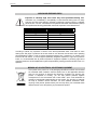 4
4
-
 5
5
-
 6
6
-
 7
7
-
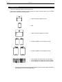 8
8
-
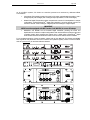 9
9
-
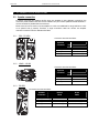 10
10
-
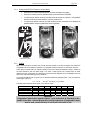 11
11
-
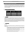 12
12
-
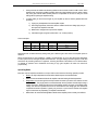 13
13
-
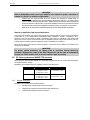 14
14
-
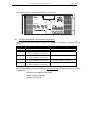 15
15
-
 16
16
-
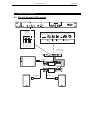 17
17
-
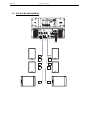 18
18
-
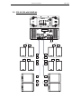 19
19
-
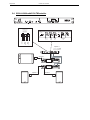 20
20
-
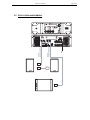 21
21
-
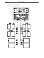 22
22
-
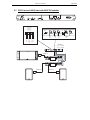 23
23
-
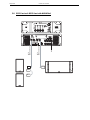 24
24
-
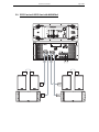 25
25
-
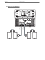 26
26
-
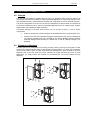 27
27
-
 28
28
-
 29
29
-
 30
30
-
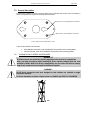 31
31
-
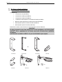 32
32
-
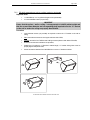 33
33
-
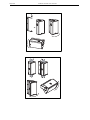 34
34
-
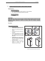 35
35
-
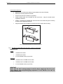 36
36
-
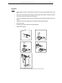 37
37
-
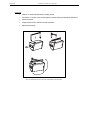 38
38
-
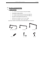 39
39
-
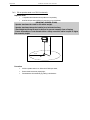 40
40
-
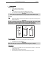 41
41
-
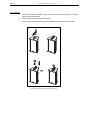 42
42
-
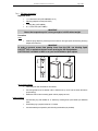 43
43
-
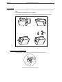 44
44
-
 45
45
-
 46
46
-
 47
47
-
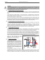 48
48
-
 49
49
-
 50
50
-
 51
51
-
 52
52
-
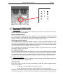 53
53
-
 54
54
-
 55
55
-
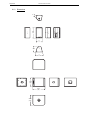 56
56
-
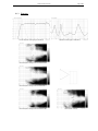 57
57
-
 58
58
-
 59
59
-
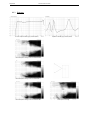 60
60
-
 61
61
-
 62
62
-
 63
63
-
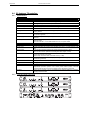 64
64
-
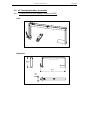 65
65
-
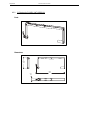 66
66
-
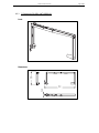 67
67
-
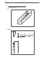 68
68
-
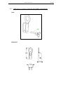 69
69
-
 70
70
-
 71
71
-
 72
72
-
 73
73
-
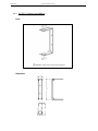 74
74
-
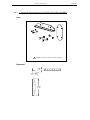 75
75
-
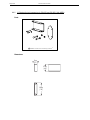 76
76
-
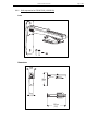 77
77
-
 78
78
-
 79
79
-
 80
80
-
 81
81
-
 82
82


Nexo PS10 Manual de usuario
- Categoría
- Equipo de música suplementario
- Tipo
- Manual de usuario
en otros idiomas
- français: Nexo PS10 Manuel utilisateur
- italiano: Nexo PS10 Manuale utente
- English: Nexo PS10 User manual
- Deutsch: Nexo PS10 Benutzerhandbuch
- русский: Nexo PS10 Руководство пользователя
- Nederlands: Nexo PS10 Handleiding
- português: Nexo PS10 Manual do usuário
- dansk: Nexo PS10 Brugermanual
- polski: Nexo PS10 Instrukcja obsługi
- čeština: Nexo PS10 Uživatelský manuál
- svenska: Nexo PS10 Användarmanual
- 日本語: Nexo PS10 ユーザーマニュアル
- Türkçe: Nexo PS10 Kullanım kılavuzu
- română: Nexo PS10 Manual de utilizare
Artículos relacionados
Otros documentos
-
DAS DX-100-230 Manual de usuario
-
BEGLEC D2-1500 El manual del propietario
-
Yamaha N-12 Manual de usuario
-
-
 Bowers & Wilkins DM630i Manual de usuario
-
HK Audio CPQ 10 Manual de usuario
-
 Rigid Industries 920314 El manual del propietario
-
LAB Gruppen IPD 2400 Guía de inicio rápido
-
RF Elements AH20-CC Manual de usuario
-
QSC K12 Manual de usuario

