Peavey Classic 50 410 Guitar Combo Amp El manual del propietario
- Categoría
- Amplificador de instrumentos musicales
- Tipo
- El manual del propietario

www.peavey.com
Classic
®
50
GUITAR AMPLIFIER
Operating
Manual

FCC/ICESCompliancyStatement
ThisdevicecomplieswithPart15oftheFCCrulesandIndustryCanadalicense‐exemptRSSStandard(s).Operationis
subjecttothefollowingtwoconditions:(1)thisdevicemaynotcauseharmfulinterference,and(2)thisdevicemust
acceptanyinterferencereceived,thatmaycauseundesiredoperation.
LeprésentappareilestconformeauxCNRd’lndustrieCanadaapplicablesauxappareilsradioexemptsde
licence.L’exploitationestautoriséeauxdeuxconditionssuivantes:(1)I’appareilnedoitpasproduirede
brouillage,et(2)I’utilisateurdeI’appareildoitacceptertoutbrouillageradioélectriquesubi,mêmesile
brouillageestsusceptibled’encompromettrelefonctionnement.
Warning:ChangesormodificationstotheequipmentnotapprovedbyPeaveyElectronicsCorp.canvoidthe
user’sauthoritytousetheequipment.
Note–ThisequipmenthasbeentestedandfoundtocomplywiththelimitsforaClassBdigitaldevice,
pursuanttoPart15oftheFCCRules.Theselimitsaredesignedtoprovidereasonableprotectionagainst
harmfulinterferenceinaresidentialinstallation.Thisequipmentgenerates,uses,andcanradiateradio
frequencyenergyand,ifnotinstalledandusedinaccordancewiththeinstructions,maycauseharmful
interferencetoradiocommunications.However,thereisnoguaranteethatinterferencewillnotoccurina
particularinstallation.Ifthisequipmentdoescauseharmfulinterferencetoradioortelevisionreception,
whichcanbedeterminedbyturningtheequipmentoffandon,the userisencouragedtotryandcorrectthe
interferencebyoneormoreofthefollowingmeasures.
Reorient or relocate the receiving antenna.
Increase the separation between the equipment and receiver.
Connect the equipment into an outlet on a circuit different from that to which the receiver is
connected.
Consult the dealer or an experienced radio/TV technician for help.
Caution
The equipment complies with FCC radiation exposure limits set forth for an uncontrolled
environment.

ENGLISH
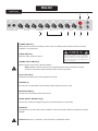
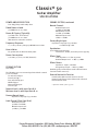
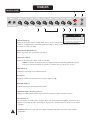
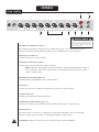
STANDBY SWITCH (1)
Allows amp to be placed in standby or active mode. In standby mode the tubes remain hot, but the
amplifier is not operational.
POWER SWITCH (2)
Switch to “ON” position to turn on.
CHANNEL SELECT SWITCH (3)
Allows selection of the Lead or Normal channels.
NOTE: Channel selection may also be accomplished by the remote footswitch. If remote
selection is desired the channel switch must be in the Lead position.
PILOT LIGHT LED (4)
Illuminates when AC power is being supplied to the amp.
PRESENCE (5)
An active tone control that boosts the extreme high frequencies by up to 6 dB.
MASTER VOLUME (6)
Controls the overall volume level of the system.
TREBLE, MIDDLE, AND BASS EQ (7)
Passive tone controls that regulate high, mid, and low frequencies, respectively.
REVERB (8)
Reverberation is an echo effect. Rotate clockwise to increase the effect. Remote footswitch can control
ON/OFF.
Ventilation: Allow 24" of clearance on all sides from a combustible surface.
Front Panel
WARNING
THE ON/OFF SWITCH IN THIS APPARATUS
DOES NOT BREAK BOTH SIDES OF THE MAINS.
HAZARDOUS ENERGY MAY BE PRESENT INSIDE
THE ENCLOSURE WHEN THE POWER SWITCH IS
IN THE OFF POSITION.
2356
4 1
8 7

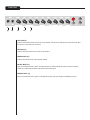
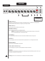
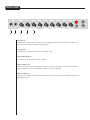
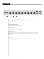
POST GAIN (9)
Controls the overall volume level of the Lead channel. The final level adjustment should be made after
the desired sound has been achieved.
PRE GAIN (10)
Controls the input volume level of the Lead channel.
NORMAL GAIN (11)
Controls the volume level of the Normal channel.
BRIGHT INPUT (12)
Input for instrument-level signals. This input produces enhanced high frequency response (treble),
similar to a bright switch, when compared to the normal input.
NORMAL INPUT (13)
Input for instrument-level signals. For brighter frequency response (highs) see Bright Input (12).
Front Panel
13 12 11 10 9

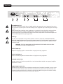
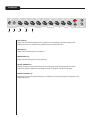
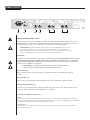
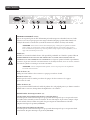
Rear Panel
AC POWER INLET (14)
This is the receptacle for an IEC line cord, which provides AC power to the unit. Connect the line cord to
this connector to provide power to the unit. Damage to the equipment may result if improper line voltage
is used.
Never break off the ground pin on any equipment. It is provided for your safety. If the outlet used does
not have a ground pin, a suitable grounding adapter should be used and the third wire should be
grounded properly. To prevent the risk of shock or fire hazard, always make sure that the amplifier and
all associated equipment is properly grounded.
FUSE (15)
The fuse is located within the cap of the fuseholder. If the fuse should fail, IT MUST BE REPLACED
WITH THE SAME TYPE AND VALUE IN ORDER TO AVOID DAMAGE TO THE EQUIPMENT AND TO PREVENT
VOIDING THE WARRANTY. If the amp repeatedly blows fuses, it should be taken to a qualified service
center for repair.
WARNING: THE FUSE SHOULD ONLY BE REPLACED WHEN THE POWER CORD HAS BEEN
DISCONNECTED FROM ITS POWER SOURCE.
EFFECTS SEND (16)
Output for supplying signals to external effects or signal processing equipment
EFFECTS RETURN (17)
Input for returning signals from external effects or signal processing equipment.
SPEAKER OUTPUTS (18)
Speaker output (1/4") jacks are provided for 16 and 8 ohms. When both jacks are engaged, amplifier
impedance is 8 ohms.
REMOTE SWITCH JACKS (19)
Provided for the connection of the included two switch remote footswitch. Footswitch is used to select
the Lead or Normal channels, and control the boost function. An optional one-button footswitch (not
included, part# 03050680) can be connected to defeat reverb. When using remote footswitch, always
insert the plug fully (second click) to ensure proper operation.
1514 16 17 1918

Classic
®
50
Guitar Amplifier
SPECIFICATIONS
POWER AMPLIFIER SECTION
Four 6BQ5/EL84’s with 12AX7 driver
Rated Power & Load:
50 W RMS into 16 or 8 ohms
Power @ Clipping (Typically):
(5% THD, 1 kHz, 120 V AC line)
50 W RMS into 16 or 8 ohms
(Bias must be reduced to measure)
Frequency Response:
+0, -2 dB, 50 Hz to 15 kHz, @ 40 W RMS into 16 ohms
Hum & Noise:
No greater than 80 dB below rated power
Power Consumption:
200 watts, 50/60 Hz, 120 VAC (Domestic)
PREAMP SECTION
Two 12AX7’s
The following specs are measured @ 1 kHz with the controls
preset as follows:
Pre & Post (lead) @ 0
Reverb Level @ 0
Bass & Treble EQ @ 12
Middle EQ @ 0
Master Volume @ 12
Presence @ 6
Nominal level is with Input Gain @ 6.
Minimum level is with Input Gain @ 12.
Preamp Normal Input:
Impedance: Very high Z, 470 K ohms
Lead Channel (Post Gain @ 10):
Nominal Input Level:
-40 dBV, 10 mV RMS
Minimum Input Level:
-70 dBV, 0.3 mV RMS
PREAMP SECTION, continued
Normal Channel:
Nominal Input Level:
-17 dBV, 140 mV RMS
Minimum Input Level:
-28 dBV, 40 mV RMS
Maximum Input Level:
0 dBV, 1.0 V RMS
Preamp Bright Input:
Impedance: Very high Z, 470 K ohms
+12 dB boost @ 2 kHz
Equalization:
(Lead and Normal Channels)
Custom bass, middle, and treble passive-type EQ
Effects Send:
Load Impedance: 1 K ohm or greater
Nominal Output Level: -6 dBV, 0.5 V RMS
Effects Return:
Impedance: High Z, 2 M ohms
Designed Input Level: -6 dBV, 0.5 V RMS
(Switching jack provides Effects Send to Effects Return
connection when not used.)
External Footswitch Function:
Reverb Defeat (when reverb control is raised)*
Normal/Lead Channel Select (when Lead activated)
Boost Function Select
* Optional footswitch, part # 03050680
Peavey Electronics Corporation • 5022 Hartley Peavey Drive • Meridian, MS 39305
Phone: (601) 483-5365 • Fax: (601) 486-1278 • www.peavey.com • 80307527

DEUTSCH
POWER-Schalter (2)
Zum Einschalten diesen Schalter auf „ON“ stellen.
STANDBY-Schalter (1)
Ermöglicht es, den Verstärker in den Standby- bzw. Betriebsmodus
zu schalten. Im Standby-Modus
werden die Röhren weiter beheizt, das Signal ist jedoch abgeschaltet.
KANALWAHLSCHALTER (3)
Zum Umschalten zwischen Lead- und Normal-Kanal.
HINWEIS: Die Kanalumschaltung kann auch über den Fußschalter erfolgen. In diesem Fall
muss der Kanalwahlschalter auf Lead-Kanal stehen.
PILOT-LAMPE (4)
Diese Betriebslampe leuchtet auf, wenn der Verstärker mit Wechselstrom versorgt wird.
PRESENCE (5)
Aktiver Klangregler, mit dem die extrem hohen Frequenzen um bis zu 6 dB angehoben werden.
MASTER VOLUME (6)
Regler für die Gesamtlautstärke des Systems.
TREBLE-, MIDDLE- UND BASS-EQ (7)
Passive Klangregler, die jeweils die Höhen, Mitten und Bässe bearbeiten.
REVERB (8)
Eingebautes Echo-Hall-System. Durch Drehen im Uhrzeigersinn wird der Effekt verstärkt. Das Ein- und
Ausschalten erfolgt über den Fußschalter.
Belüftung: Belassen Sie an allen Seiten 61 cm Abstand zu brennbaren Flächen.
Vorderseite
WARNUNG
DER AN/AUS SCHALTER IN DIESEM GERÄT UNTERBRICHT
NICHT BEIDE SEITEN DES NETZES. AUCH WENN DER
SCHALTER AUF "AUS" STEHT KANN IM INNERN DES
GERÄTES IMMER NOCH GEFÄHRLICHE ELEKTRISCHE
ENERGIEN VORHANDEN SEIN.
2356
4 1
8 7

POST GAIN (9)
Regelt den Gesamtlautstärkepegel des Lead-Kanals. Die endgültige Lautstärkeregelung sollte
vorgenommen werden, nachdem der gewünschte Sound eingestellt wurde.
PRE GAIN (10)
Regelt den Vorstufenpegel des Lead-Kanals.
NORMAL GAIN (11)
Regelt den Lautstärkepegel des Normal-Kanals.
BRIGHT-EINGANG (12)
Eingang für Signale mit Instrumentenpegel. Dieser Eingang erhöht die Wiedergabe der hohen
Frequenzen (Treble), ähnlich wie beim Bright-Schalter im Vergleich zum Normal-Eingang.
NORMAL-EINGANG (13)
Eingang für Signale mit Instrumentenpegel. Für brillantere Frequenzwiedergabe in den Höhen siehe
Bright-Eingang (12).
Vorderseite
13 12 11 10 9

Rückseite
NETZBUCHSE (14)
Dies ist der Anschluss für ein IEC-Netzkabel, welches das Gerät mit Netzspannung versorgt. Schließen Sie das Netzkabel an diese
Buchse an, um das Gerät mit Strom zu versorgen. Durch Verwendung der falschen Netzspannung kann die Ausrüstung beschädigt
werden. (Beachten Sie die Spannungsangaben auf dem Gerät).
Warnung: Brechen Sie niemals den Erdungspol eines Gerätes ab. Er dient zu Ihrer Sicherheit. Falls die Steckdose, die Sie
verwenden, nicht geerdet ist, sollten Sie einen geeigneten Erdungsadapter verwenden und der dritte Leiter sollte
ordnungsgemäß geerdet sein. Um das Risiko eines Stromschlags oder Brandes zu vermeiden, sollten Sie sich immer
vergewissern, dass der Verstärker und alle dazugehörigen Ausrüstungsteile ordnungsgemäß geerdet sind.
FUSE
(15)
Die Sicherung befindet sich in der Kappe des Sicherungshalters. Wenn die Sicherung durchbrennt, MUSS
SIE DURCH EINE SICHERUNG DES GLEICHEN TYPS UND DES GLEICHEN WERTES ERSETZT WERDEN, UM
BESCHÄDIGUNG DER AUSRÜSTUNG ZU VERHÜTEN UND DIE GARANTIE NICHT UNWIRKSAM ZU MACHEN.
Wenn der Verstärker wiederholt Durchbrennen der Sicherung verursacht, sollte er zur Reparatur zu
einem qualifizierten Wartungszentrum gebracht werden.
ACHTUNG: DIE SICHERUNG SOLLTE NUR AUSGEWECHSELT WERDEN, WENN DAS NETZKABEL VON DER
STROMVERSORGUNG ABGETRENNT WORDEN IST.
LAUTSPRECHERAUSGÄNGE (18)
Für die Lautsprecherausgänge stehen Klinkenbuchsen (1/4”) für 16 und 8 Ohm zur Verfügung. Sind beide Buchsen belegt,
beträgt die Impedanz des Verstärkers 8 Ohm.
REMOTE-SWITCH-ANSCHLUSS (19)
BOOST SCHALTERBUCHSE:
Für Anschluss des optionalen Fernfußschalters. Der Fußschalter wird zur Wahl von Leit- oder Hauptkanälen und zur Boost-
Aktivierung verwendet. Schieben Sie bei Verwendung des Fernfußschalters den Stecker immer vollständig (bis zum 2. Klick) ein,
um korrekten Betrieb sicherzustellen (erfordert Peavey-Fußschalter 03054360)
REVERB-SCHALTERBUCHSE:
Für Anschluss des optionalen Fernfußschalters. Der Fußschalter wird zur Deaktivierung von Nachhall verwendet (erfordert Peavey-
Fußschalter 03051000)
EFFECTS RETURN (17)
Eingang für die von externen Effektgeräten oder Signalbearbeitungsgeräten gelieferten Signale.
EFFECTS SEND (16)
Ausgang für die Weiterleitung von Signalen an externe Effektgeräte oder Signalbearbeitungsgeräte.
1514 16 17 1918

Classic
®
50
Gitarrenverstärker
TECHNISCHE DATEN
ENDSTUFE
Vier 6BQ5/EL84-Röhren mit 12AX7-Treiber
Nennleistung und Nennlast:
50 W RMS an 16 oder 8 Ohm
Leistung bei Clipping (typisch):
(5% THD, 1 kHz, 120 V Wechselstromleitung)
50 W RMS an 16 oder 8 Ohm
(Vorspannung muss für Messung verringert werden)
Frequenzverhalten:
+0, -2 dB, 50 Hz bis 15 kHz bei 40 W RMS an 16 Ohm
Brummen und Rauschen:
Nicht über 80 dB unter Nennleistung
Leistungsaufnahme:
200 Watt, 50/60 Hz, 120 V Wechselstrom (USA)
VORVERSTÄRKERSTUFE
Zwei 12AX7-Treiber
Die folgenden technischen Daten wurden bei 1 kHz mit
folgenden Reglereinstellungen gemessen:
Pre/Post (Lead-Kanal) auf 0
Reverb-Pegel auf 0
Bass- und Treble-EQ auf 12
Middle-EQ auf 0
Master Volume bei 12
Presence auf 6
Nennpegel bei Eingangs-Gain auf 6
Mindestpegel bei Eingangs-Gain auf 12
Vorverstärkereingang (Normal):
Impedanz: Sehr hochohmig, 470 kOhm
Lead-Kanal (Post Gain auf 10):
Nenneingangspegel:
-40 dBV, 10 mV RMS
Mindesteingangspegel:
-70 dBV, 0,3 mV RMS
VORVERSTÄRKERSTUFE, Fortsetzung
Normal-Kanal:
Nenneingangspegel:
-17 dBV, 140 mV RMS
Mindesteingangspegel:
-28 dBV, 40 mV RMS
Max. Eingangspegel:
0 dBV, 1,0 V RMS
Vorverstärker-Bright-Eingang:
Impedanz: Sehr hochohmig, 470 kOhm
+12 dB Anhebung bei 2 kHz
Abgleich:
(Lead- und Normal-Kanal)
Spezieller passiver Bass-, Middle- und Treble-EQ
Effects Send:
Verbraucherimpedanz: 1 kOhm oder darüber
Nennausgangspegel: -6 dBV, 0,5 V RMS
Effects Return:
Impedanz: Hochohmig, 2 MOhm
Ausgelegter Eingangspegel: -6 dBV, 0,5 V RMS
(Bei Nichtverwendung ermöglicht Schaltklinke Anschluss
zwischen Effects Send und Effects Return)
Funktionen des externen Fußschalters:
Reverb-Deaktivierung (Reverb-Regler ist nicht gedrückt)
Auswahl Normal-/Lead-Kanal (Lead-Kanal ist aktiviert)

FRANÇAIS
Interrupteur d’alimentation (2)
Mettre en position “On” pour mettre sous tension.
Sélecteur attente (1)
Permet de sélectionner l’état de l’ampli: mode “Active” (actif) ou mode “Standby” (attente). En position
“Stand-by”, l’amplificateur ne fonctionne pas mais les lampes (“tubes”) restent chaudes pour permettre de
le remettre en service sans délai.
Sélecteur de canal (3)
Permet de sélectionner les canaux “Lead” ou “Normal”.
NOTE: La sélection de canal peut aussi s’accomplir à distance à l’aide de la pédale-interrupteur.
Pour que la sélection à distance soit possible, le canal doit être en position “In” (“Lead”).
DEL témoin (4)
S’allume lorsque l’ampli reçoit l’alimentation CA.
Presence (5)
Réglage de tonalité actif qui renforce les fréquences aiguës (+6 dB).
Principal volume (6)
Contrôle le niveau de volume général du système.
Egalisation aiguës, moyennes, graves (7)
Réglages de tonalité passif ajustant respectivement les fréquences aiguës, moyennes et graves.
Réverbération (8)
La réverbération est un effet d’écho. Tournez dans le sens du mouvement des aiguilles d’une montre pour
augmenter l’intensité de l’effet. L’interrupteur au pied peut contrôler la mise en circuit ou hors circuit
(“On/Off’).
Ventilation: Liberez un espace vide pour chaque extrémités d’une distance de 24" de toutes surfaces
combustibles.
PANNEAU AVANT
ATTENTION
L'INTERRUPTEUR D'ALIMENTATION NE COUPE PAS
CELLE-CI AUX DEUX BORNES ET DE L'ENERGIE
ELECTRIQUE PEUT ETRE PRESENTE DANS CERTAINS
COMPOSANTS APRES LA MISE HORS-TENSION.
2356
4 1
8 7

Post gain (9)
Commande le volume général du canal “Lead”. Le réglage final de niveau doit être effectué après avoir
obtenu la sonorité désirée a l’aide des autres réglages.
Pre gain (10)
Contrôle le niveau de volume a l’entrée sur du canal “Lead”.
Gain canal normal (11)
Contrôle le niveau de volume du canal “Normal”.
Entrée “Bright” (12)
Entrée pour signaux de niveau instrument. Cette entrée produit une réponse accentuée des fréquences
aiguës, similaire a un sélecteur de brillance compare a une entrée normale.
Entrée normale (13)
Entrée pour les signaux de niveau instrument. Pour une réponse en fréquence plus brillante (hautes) voir
Bright Input No. 12.
PANNEAU AVANT
13 12 11 10 9

PANNEAU ARRIÈRE
Fusible (14)
Le fusible se trouve a l’intérieur de son support. Si le fusible grille, IL DOlT ETRE REMPLACE PAR UN
FUSIBLE DE MEME TYPE ET MEME VALEUR POUR EVITER TOUT DOMMAGE A L’APPAREIL
ET EVITER D’ANNULER LA GARANTIE. Si le fusible grille de façon répétée, apportez l’appareil a un
centre de service qualiflé pour reparation.
AVERTISSEMENT: LE FUSIBLE NE DOlT ETRE REMPLACE QUE LORSQUE LE CORDON
D’ALIMENTATION EST DE BRANCHE DE LA SOURCE D’ALIMENTATION.
Sortie pour haut-parleur (16)
Les jacks 1/4" (6,35 mm) de sortie pour haut-parleur sont prévus pour 16 et 8 ohms. Lorsque les deux
jacks sont utilisés, l’impédance de l’amplificateur est de 8 ohms.
Prise pour interrupteur a distance (17)
BOOST:
Ceci est prévu pour le raccordement de la pédale à distance en option. La pédale est utilisée pour sélectionner les canaux Lead ou
Normal et activer l’amplification. Lorsque vous utilisez la pédale à distance, toujours enfoncer complètement la prise (deuxième clic)
pour assurer un bon fonctionnement. (Nécessite la pédale Peavey 03054360)
PRISE REVERB:
Ceci est prévu pour le raccordement de la pédale à distance en option. La pédale est utilisée pour supprimer la réverbération.
(Nécessite la pédale 03051000)
Retour d’effets (17)
Prise d’entrée pour signaux provenant d’appareils externes de traitement de signal ou d’effets.
Envoi d’effets (16)
Prise de sortie servant a fournir des signaux a des appareils externes de traitement de signal ou
d’effets.
1514 16 17 1918
PRISE D'ALIMENTATION CA (14)
C'est le réceptacle pour un cordon IEC, qui fournit du courant alternatif à l'unité. Branchez le cordon
d'alimentation à ce connecteur pour alimenter l'unité. L'équipement peut être endommagé si la tension
électrique n'est pas bonne. (Voir le marquage de la tension de secteur sur l'appareil).
AVERTISSEMENT: Ne jamais débrancher la broche de terre sur un équipement. Elle est prévue pour votre
sécurité. Si l'appareil utilisé n'a pas de prise de terre, un dispositif de mise à la terre doit être utilisé, et le
troisième fil doit être mis à la terre correctement. Pour éviter les risques d'électrocution ou d'incendie, toujours
veiller à ce que l'amplificateur et tous les appareils reliés soient correctement mis à la terre.

Classic
®
50
Amplificateur guitare
SPECIFICATIONS
SECTION AMPLIFICATION
Quatre 6BQ5/EL84s avec pilote 12AX7
Puissance mesurée et charge d’impédance:
50 W RMS sous 16 ou 8 ohms
Puissance de Crête (Type):
(5% THD, 1 kHz, 120 V AC ligne)
50 W RMS sous 16 ou 8 ohms
(le Bias doit être réduit à la mesure.)
Réponse en Fréquence:
+0, -2 dB, 50 Hz à 15 kHz, @ 40 W RMS sous 16 ohms
Bruit:
Inferieur à 80 dB en dessous de la puissance mesurée
Consommation élèctrique:
200 watts, 50/60 Hz, 120 VAC (Domestique)
SECTION PREAMPLIFICATION
Deux 12AX7’s
Les spécifications suivantes sont mesurées @ 1 kHz avec les
réglages de contrôles suivants:
Pre & Post (lead) @ 0
Reverb Level @ 0
Bass & Treble EQ @ 12
Middle EQ @ 0
Master Volume @ 12
Presence @ 6
Le niveau nominal est avec un gain d’entrée @ 6
Le niveau minimal est avec un gain d’entrée @ 12
Entrée normale préamplificateur:
Impedance: Très Haute, 470 K ohms
Canal Lead (Post Gain @ 12):
Niveau d’entrée Nominal :
-40 dBV, 10 mV RMS
Niveau d’entrée Minimum :
-70 dBV, 0.3 mV RMS
SECTION PREAMPLIFICATION, continué
Canal Normal (Post Gain @ 12):
Niveau d’entrée Nominal :
-17 dBV, 140 mV RMS
Niveau d’entrée Minimum :
-28 dBV, 40 mV RMS
Niveau d’entrée Maximum :
0 dBV, 1.0 V RMS
Entrée Bright Préamplificateur:
Impedance: Très Haute, 470 K ohms
+12 dB boost @ 2 kHz
Egalisation:
(Canaux Lead et Normal)
Egaliseur passif bass, médium, et aigu de type Custom
Effects Send:
Charge d’impédance: 1 K ohm ou plus
Niveau de Sortie Nominal: -6 dBV, 0.5 V RMS
Effects Return:
Impedance: Haute, 2 M ohms
Niveau d’entrée prévu: -6 dBV, 0.5 V RMS
(Le Changement de jack fournit l’Effects Send à la connection
Effects Return si cette dernière n’est pas utilisée)
Fonction footswitch externe:
Coupure Reverb (lorsque le contrôle de Reverb est activé)
Sélection canal Normal/Lead (lorsque le canal Lead est
activé)

ESPAÑOL
Interruptor de corriente (2)
Coloque a la posición “on” para encender.
Interruptor de condición de espera (1)
Este interruptor le permite a su aparato estar en condición de”espera” o la condición de activo. En la
condición “standby” los tubos permanecen calientes, pero el amplificador no está en operación.
Interruptor de selección de canal (3)
Permite la selección del canal “Lead” (solista) o Normal.
NOTA: También se puede lograr la selección del canal por medio del pedal interruptor remoto. Si
desea la selección a control remoto, el interruptor de canal debe estar en la posición “in” (hacia
adentro) (canal de solista).
LED indicadora de lámpara piloto (4)
Se ilumina cuando el amplificador recibe corriente alterna.
Presencia (5)
Control de tono activo que aumenta en 6 dB las frecuencias de los extremos agudos.
Volumen maestro (6)
Controla el nivel global de volumen del sistema.
Ecualizador de agudos, medias y graves (7)
Controles de tono pasivo que regulan las frecuencias altas, medias y graves, respectivamente.
Reverberación (8)
La reverberación es un efecto de eco. Haga girar a la derecha para aumentar el efecto. El encendido/
apagado (“on/off”) se puede controlar con el pedal interruptor de control remoto.
Ventilación: Permita 24" (61 cm) de espacio a cada lado de una superficie inflamable.
PANEL FRONTAL
ADVERTENCIA
EL INTERRUPTOR ON/OFF DE ESTE APARATO NO
ROMPE AMBOS LADOS DEL CIRCUITO. ENERGÍA
PELIGROSA PUEDE ESTAR PRESENTE DENTRO DE LA
CAJA CUANDO EL INTERRUPTOR DE ENCENDIDO
ESTÉ EN LA POSICIÓN OFF.
2356
4 1
8 7

20
Control de ganancia posterior del preamplificador (9)
Controla el volumen general del canal solista. El ajuste final de nivel debe hacerse después de que se haya
obtenido el sonido deseado.
Control del preamplificador (10)
Controla la entrada de volumen del canal solista.
Ganancia normal (11)
Controla el nivel de volumen del canal Normal.
Entrada de brillo (12)
Esta entrada es para las señales a nivel de instrumentos. Esta entrada produce una respuesta de
frecuencias agudas (tiple) , semejante al interruptor de brillo cuando se compara con la entrada
normal.
Entrada normal (13)
Entrada para señales de nivel de instrumento. Para obtener respuestas de frecuencia más brillantes
(altas) ver Entrada de Brillo Número 12.
PANEL FRONTAL
13 12 11 10 9

PANEL TRASERO
Fusible (15)
El fusible se encuentra localizado dentro de la cápsula del portafusible. Si el fusible se quema o falla, SE
DEBERA REEMPLAZAR CON UNO DEL MISMO TIPO Y VALOR, PARA EVITAR DAÑO AL
APARATO Y EL ANULAMIENTO DE LA GARANTIA. Si el aparato quema los fusibles repetidamente,
cerciórese de que está conectado a un tomacorriente con el voltaje adecuado, si esto es correcto, entonces
desconéctelo y llévelo a revisión por un técnico autorizado.
ATENCION: Antes de reemplazar el fusible quemado, cerciórese de que el aparato está completamente
desconectado del tomacorriente.
Salidas de altavoz (18)
Se proporcionan enchufes hembras de salida de parlante de 1/4 de pulgada para 16 y 8 ohmios. Cuando se
utilizan ambos conectores, la impedancia de amplificador es de 8 ohmios.
Enchufe hembra de interruptor remoto (19)
CONECTORES DE INTERRUPTOR REMOTE CHANNEL/BOOST:
Se brinda para la conexión del interruptor de pie opcional. El interruptor de pie se usa para seleccionar
los canales Líder o Normal y activar el reforzador. Al usar el interruptor de pie remoto, siempre coloque
bien el enchufe (deberá escuchar un segundo clic) para asegurar un funcionamiento adecuado.
(Requiere interruptor de pie Peavey 03330850)
CONECTOR DE INTERRUPTOR REVERB:
Se brinda para la conexión del interruptor de pie opcional. El interruptor de pie se usa para cancelar la
reverberancia. (Requiere interruptor de pie Peavey 03330850)
Retorno de efectos (17)
Entrada para el retorno de señales procedentes de equipos de efectos externos o de equipos
procesadores de señal.
Envío de efectos (16)
Salida para enviar señales a efectos externos o equipos procesadores de señal.
1514 16 17 1918
ENTRADA DE ENERGÍA CA (14)
Este es un receptáculo para un cable de línea IEC que brinda energía CA a la unidad. Conecte el cable
de línea a este conector para proporcionar energía a la unidad. El equipo podría resultar dañado si el
voltaje de línea usado es inadecuado. (Consulte la marcación de la línea de voltaje en la unidad).
ATENCION: Nunca retire la conexión a tierra de ningún equipo. Se incluye para su seguridad. Si el enchufe
usado no cuenta con conexión a tierra, se debe usar un adaptador adecuado y el tercer cable se debe conectar a
tierra correctamente. Para prevenir riesgos de descarga eléctrica, siempre asegúrese de que el amplificador y todo el
equipo estén correctamente puestos a tierra.

22
Classic
®
50
Amplificador para Guitarra
ESPECIFICACIONES
SECCIÓN DE LA ETAPA DE POTENCIA
Cuatro 6BQ5/EL84s con 12 AX7
Potencia estimada & Carga
50 W RMS bajo 16 u 8 ohmios
Potencia en Saturación (Típicamente)
(5% THD, 1 kHz, línea de 120 VAC )
50 W RMS bajo 16 u 8 ohmios
(Debe reducir el Bias para la medición.)
Respuesta en Frecuencia:
+0, -2 dB, 50 Hz a 15 kHz, a 40 W RMS bajo 16 ohmios
Zumbido Y Ruido:
Inferior a 80 dB por debajo de la potencia estimada
Consumo de Potencia:
200 vatios, 50/60 Hz, 120 VAC (Doméstico)
SECCIÓN DE PREVIO
Dos 12AX7’s
Las siguientes especificaciones están medidas a 1 kHz con los
controles situados como sigue:
Pre & Post (lead) a 0
Nivel de Reverb a 0
EQ de Graves y Agudos a 12
EQ de Medios a 0
Volumen Master a 12
Presencia a 6
El nivel nominal es con la Ganancia de Entrada a 6
El nivel mínimo es con la ganancia de entrada a 12
Entrada Normal de Previo:
Impedancia: Z Muy Alta, 470 K ohmios
Canal Solista (Post Gain a 10):
Nivel de Entrada Nominal:
-40 dBV, 10 mV RMS
Nivel de Entrada Mínimo:
-70 dBV, 0.3 mV RMS
Sección del Previo, continuación
Canal Normal:
Nivel de Entrada Nominal:
-17 dBV, 140 mV RMS
Nivel de Entrada Mínimo:
-28 dBV, 40 mV RMS
Nivel de Entrada Máximo:
0 dBV, 1.0 V RMS
Entrada Brillante De Previo:
Impedancia: Z Muy Alta, 470 K ohmios
Incremento del +12 dB a 2 kHz
Ecualización:
(Canales Solista y Normal)
EQ pasiva de graves, medios, y agudos especialmente
diseñada
Envío de Efectos:
Carga de Impedancia: 1 K ohmio o mayor
Nivel de Salida Nominal: -6 dBV, 0.5 V RMS
Retorno de Efectos:
Impedancia: Z Alta, 2 M ohmios
Nivel de entrada diseñado: -6 dBV, 0.5 V RMS
(el jack interruptor proporciona conexión Effects Send a Effects
Return cuando no se usa.)
Función del Pedal Externo:
Anulación de la reverb (cuando el control de reverb control
está levantado)
Selección de canal Normal/Lead (con el Lead activado)

Logo referenced in Directive 2002/96/EC Annex IV
(OJ(L)37/38,13.02.03 and defined in EN 50419: 2005
The bar is the symbol for marking of new waste and
is applied only to equipment manufactured after
13 August 2005
www.peavey.com
Warranty registration and information for U.S. customers available online at
www.peavey.com/warranty
or use the QR tag below
Features and specications subject to change without notice.
Peavey Electronics Corporation 5022 Hartley Peavey Drive Meridian, MS 39305 (601) 483-5365 FAX (601) 486-1278
-
 1
1
-
 2
2
-
 3
3
-
 4
4
-
 5
5
-
 6
6
-
 7
7
-
 8
8
-
 9
9
-
 10
10
-
 11
11
-
 12
12
-
 13
13
-
 14
14
-
 15
15
-
 16
16
-
 17
17
-
 18
18
-
 19
19


Peavey Classic 50 410 Guitar Combo Amp El manual del propietario
- Categoría
- Amplificador de instrumentos musicales
- Tipo
- El manual del propietario
En otros idiomas
Documentos relacionados
-
Peavey 50 410 Manual de usuario
-
 Peavy Classic 50 212 Manual de usuario
-
-
-
-
-
-
-
-
