
Table of Contents
1. Important Safety Instructions 2
2. Overview 2
3. Feature Identification 3
4. Enclosure Installation 4
4.1 Preparation 4
4.2 Unpacking 4
4.3 Ground Connection 4
5. Enclosure Configuration 5
5.1 Door Locks 5
5.2 Cable Access & Management 5
5.3 Reversing the Enclosure 5
5.4 Mounting Rails 6
5.5 Adjusting Mounting Rail Depth 6
6. Wall-Mounting the Enclosure 6
7. Equipment Installation 7
7.1 Installing or Removing Cage Nuts 7
7.2 Alternate Mounting: 7
Tapped Hole Mounting Rail
7.3 Rack-Mount Installation 8
7.4 Cable Routing 8
8. Storage and Service 8
9. Warranty and Product Registration 9
Español 10
Français 19
28
Non-Swinging Wall-Mounted
SmartRack
®
Enclosure
Models: SRW6UDPVRT, SRW6UDPGVRT
(Series Number: AG-00EA)
Owner’s Manual
1111 W. 35th Street, Chicago, IL 60609 USA • www.tripplite.com/support
Copyright © 2018 Tripp Lite. All trademarks are the sole property of their respective owners.
PROTECT YOUR INVESTMENT!
Register your product for quicker service and ultimate peace of mind.
You could also win an ISOBAR6ULTRA surge protector—a $100 value!
www.tripplite.com/warranty

2
1. Important Safety Instructions
2. Overview
SAVE THESE INSTRUCTIONS
This manual contains instructions and warnings that must be followed during the installation and operation of the product described in this manual.
Failure to comply may invalidate the warranty and cause property damage or personal injury.
• Keep the enclosure in a controlled indoor environment, away from moisture, temperature extremes, flammable liquids and gasses, conductive
contaminants, dust and direct sunlight.
• Leave adequate space at the front and rear of the enclosure for proper ventilation. Do not block, cover or insert objects into the external ventilation
openings of the enclosure.
• The enclosure is extremely heavy. Use caution when handling the enclosure. Do not attempt to unpack, move or install it unassisted. Use a
mechanical device such as a forklift or pallet jack to move the enclosure in the shipping container.
• Do not place any object on the enclosure, especially containers of liquid, and do not attempt to stack the enclosures.
• Inspect the shipping container and the enclosure for shipping damage. Do not use the enclosure if it is damaged.
• Leave the enclosure in the shipping container until it has been moved as close to the final installation location as possible.
• Install the enclosure in a structurally sound area capable of handling the load, or on a level floor that is able to bear the weight of the enclosure, all
equipment that will be installed in the enclosure and any other enclosures and/or equipment that will be installed nearby.
• For permanent wall mounting, be sure to securely fasten the enclosure to the building structure before operation.
• Use caution when cutting packing materials. The enclosure could be scratched, causing damage not covered by the warranty.
• Save all packing materials for later use. Repacking and shipping the enclosure without the original packing materials may cause product damage
that will void the warranty.
• Do not reship the enclosure with additional equipment. The combined weight of the enclosure and installed equipment must not exceed the load
capacity of the pallet. Tripp Lite is not responsible for any damage that occurs during reshipment.
• Use of this equipment in life support applications where failure of this equipment can reasonably be expected to cause the failure of the life support
equipment or to significantly affect its safety or effectiveness is not recommended.
Non-swinging wall-mounted SmartRack enclosures accommodate all standard 19-inch rack-mount equipment, regardless of vendor, and ship fully
assembled for quick and easy deployment. They feature adaptable, heavy-duty cabinets in various heights.
Non-swinging wall-mounted SmartRack enclosures have variable mounting depths. The cabinets include quick-release doors and side panels for
convenient maintenance. Front access doors are reversible for installation flexibility. Front door and side panels are lockable. Front and rear vertical
cable managers and four cable pass-through ports located on the top and bottom of the cabinets allow for easy, organized cable routing.

3
3. Feature Identification
1
Front Door
(Clear acrylic window included with
SRW6UDPGVRT model)
2
Horizontal Rails
3
Vertical Mounting Rails (Adjustable)
4
Cable Access Hole Cover (Removable)
5
Ventilation Fan Ports
6
Locking/Removable Side Panels with Ventilation Fan Ports
7
Cable Pass-Through with Brush Strip
8
Cable Tie Cut Outs
9
Vertical Cable Manager with Finger Ducts
10
Ground Stud
11
Mounting Notches
12
Mounting Plate with Hooks
12
11
9
9
4
4
10
2
2
3
3
5
6
6
7
7
8
8
1

4
4.2 Unpacking
4.3 Ground Connection
All parts of the enclosure are grounded to the frame of the enclosure. Near the rear of the
enclosure cabinet, use the grounding stud
A
and an M6 screw (included) and 8 AWG (3.264 mm)
wire to connect the enclosure frame directly to your facility’s earth ground connection. Route the
ground wire either by removing the bottom rear cable access hole cover or running the wire through
the rear of the enclosure cabinet. Warning: Attach each enclosure to earth ground separately.
Do not use the enclosure without an earth ground connection.
Use at least two people to unpack the enclosure.
Never extend more than one component from the enclosure at a time.
Warning: Never attempt to lift or install without adequate help.
Do not try lifting the enclosure alone.
1
Move shipping pallet to a firm, level surface.
2
Open box and remove the four foam corner protectors. Save all packing materials for later use unless you are certain they will not be required.
Packing materials are recyclable.
3
With one person on each side, carefully lift the enclosure out of the box and place on a firm, level surface.
4
Examine the enclosure for any damage or loose parts. Confirm all parts are present. If anything is missing or damaged, contact Tripp Lite for
assistance. Do not attempt to use the enclosure if it has been damaged.
4. Enclosure Installation
Caution! Read All Instructions and Warnings Before Installation!
Warning: Rack enclosures can be extremely heavy. Do not attempt to unpack, move or install the enclosure without assistance.
Use extreme caution when handling the enclosure and be sure to follow all handling and installation instructions. Do not
attempt to install equipment without first stabilizing the enclosure.
4.1 Preparation
The enclosure must be installed in a structually sound area that is able to bear the weight of the enclosure, all the equipment that will be installed in
the enclosure and any other enclosures and/or equipment that will be installed nearby. Before unpacking the enclosure, you should transport the
shipping container closer to the final installation location to minimize the distance you will need to move the unit after the protective packaging has
been removed. If you plan to store the enclosure for an extended period before installation, follow the instructions in the Storage and Service
section.
You need several tools:
• Level
• Phillips-head screwdriver
• Appropriate tools for wall mounting
You also need the following hardware:
• Appropriate hardware for wall mounting (not included)
EARTH
GROUND
OR
A

5
5. Enclosure Configuration
5.1 Door Locks
5.2 Cable Access and Management
5.3 Reversing the Enclosure
The front and back doors have locks that are accessible with the included keys.
Each side panel locks using an L-shaped lever on the inside of the enclosure.
1
To unlock and remove the side panels, lift the shorter leg of the “L” up and pull it away from the
side panel. Pull the tab on the side panel and remove it from the enclosure.
2
To re-lock the side panels, secure it in the proper position, lift the shorter leg of the “L” up and
push it toward the side panel, back into the hole that it was in initially. Once it is in place, push
the shorter leg of the “L” down to lock it.
Note: To lock and unlock the side panels, you will need to have access to the interior of the enclosure.
Several cable access and management options are available, depending on your installation.
Cable Access Hole with Cover
The top of the cabinet has a rectangular opening for cable access and management. This opening
can be opened or closed by unscrewing or screwing in the removable cable access panel.
Cable Pass-Throughs with Brush Strips
Four cable pass-through ports located on the top and bottom of the cabinets allow for easy,
organized cable routing. See section 7.5 Cable Routing for more information.
In order to accommodate various rack configurations, the enclosure can be reversed. To do so, simply turn the enclosure over so that the doors open
in the opposite direction.
Before installation, be sure to plan the location and arrangement of components within the enclosure. Be sure all mounting rails are reversed or
adjusted for depth, depending on your equipment configuration.
1
2

6
5. Enclosure Configuration continued
6. Wall Mounting the Enclosure
5.4 Mounting Rails
5.5 Adjusting Mounting Rail Depth
The enclosure comes with mounting rails that have both square and tapped holes for mounting rack
equipment. To install equipment, use the included cage nuts and other hardware (See section 7.1
for installation of cage nuts.) Warning: Be sure to have the enclosure securely mounted to
the wall, or in its final position on the floor, before mounting any equipment inside.
Also be sure to have all the right adjustments on your rails before mounting
equipment. (See below for Adjusting Mounting Rail Depth.)
Warning: Do not attempt to adjust rails while equipment is installed in the enclosure.
Do not attempt to use rails without screws installed (2 per rail).
The 2 mounting rails are pre-installed to accommodate different mounting depths, depending on
the model. Do not adjust the mounting rails unless your equipment requires a different mounting
depth. The front and rear sets of rails can be adjusted independently in 3/4-inch (19 mm)
increments.
1
Each rail is connected to the enclosure with 2 screws and 2 cage nuts: 1 set in the upper
corner and another in the lower corner. Using a Phillips-head screwdriver, remove the screws
that fasten the rails to the enclosure.
2
Move cage nuts to the desired depth and reinstall.
3
Slide the mounting rails to the desired depth and reattach them using the screws you removed in
Step 1.
Warning: Do not attempt to mount the enclosure to the wall with equipment in the enclosure.
Note: Enclosure must be installed by a qualified technician. Before mounting, use a level and tape measure to position your mounting area precisely. Use appropriate
fasteners (not included) to secure the enclosure to the wall. Use suitable mounting means when installing to cinder block, concrete, drywall or wood studs. Warning: The
supporting surface must be able to safely support the combined load of the equipment and all attached hardware and components. For the actual weight,
size and load capacity of the enclosure, view the product specifications and other support resources at
www.tripplite.com/support.
1
Using user-supplied hardware, attach the
mounting plate to a wall or other suitable
mounting surface. Each mounting hole can
accommodate an M8 or 5/16” bolt and the
holes are spaced 16" apart to
accommodate standard stud placement as
reflected in the diagram.
Note: When mounting the mounting plate to the
wall, be sure the three mounting hooks are facing
outwards and away from the wall.
2
After the mounting plate has been securely
attached to the mounting surface, hang the
enclosure’s three mounting notches onto
the three mounting hooks on the plate
attached to the wall. The notches will fit
over the hooks and the enclosure should
slide down onto the hooks until secure.
Note: Mounting notches exist on both the upper
and lower rails of the back panel. This allows for
mounting in the standard or reversed positions.
3
After the mounting plate has been secured
and the enclosure hung properly, secure the
enclosure to the mounting plate by installing
the three supplied screws in the holes on
the mounting hooks as shown.
16”
2.75”
2.75”
16”
A
A
B
B
C
C
1
2
3
1 2 3

7
7. Equipment Installation
7.1 Installing or Removing Cage Nuts
Warning: Do not install equipment until you have stabilized the enclosure. Install heavier equipment first towards the bottom of
the enclosure. Install equipment starting from the bottom of the enclosure and proceed toward the top of the enclosure - never
the reverse. If using sliding equipment rails, be careful when extending the rails. Do not extend more than one set of sliding
equipment rails at one time. Avoid extending sliding equipment rails near the top of the enclosure.
Note: The unit comes with two different kinds of screws for equipment installation, black and silver. Use the black mounting screws if you are securing your equipment to
the square hole side of the mounting rail. Use the silver screws if you are securing your equipment to the tapped hole side of the mounting rail.
Note: The square holes in the middle of each rack unit are numbered and also include a small notch to aid identification. A single rack unit includes the space occupied
by the numbered hole and the holes directly above and below.
To Remove Cage Nuts, Reverse Steps 1-3
Note: You may wish to use a cage nut tool (user-supplied) to aid cage nut installation and removal.
WARNING: The flanges of the cage nuts should engage the sides of the square opening in the rail, not the top and bottom. Follow
the instructions in your equipment documentation to ensure proper installation of your equipment.
1
Locate the numbered square openings in
the mounting rails where you plan to install
your equipment. You will install cage nuts
(included) into the square openings in order
to provide an attachment point for the
mounting screws (included).
Note: Consult your equipment documentation to
determine how many cage nuts will be required
and where they will need to be installed.
2
From the inside of the mounting rail, insert
one of the flanges of the cage nut through
the square opening. Press it against the
side of the square opening. Each flange
should engage one side of the square
opening, not the top or bottom.
3
Compress the cage nut at the sides slightly
to allow the remaining flange to fit through
the square opening. When the cage nut is
properly installed, both flanges will protrude
through the square opening and will be
visible on the outer surface of the mounting
rail. Repeat steps 1-3 until all required cage
nuts are installed.
7.2 Alternate Mounting: Tapped Hole Mounting Rail
Warning: Do not attempt to adjust rails while equipment is installed in the enclosure. Do not attempt to use rails without screws
installed. (2 per rail.)
The 2 mounting rails are pre-installed for securing equipment using the square hole side of the mounting rail. To switch to the tapped hole side of the
mounting rail, follow the steps below:
1
Each rail is connected to the enclosure with
2 screws: 1 in the upper corner and another
in the lower corner. Using a Phillips-head
screwdriver, remove the screws that fasten
the rails to the enclosure.
2
Switch the rail locations. Ensure the tapped
hole side of each rail is facing the front
door.
3
Reattach the mounting rails.
2
19
18
22
3
2
19
18
22
3
2
19
18
22
3
24
25
26
27
28
29
23
22
21
20
19
18
24
25
26
27
28
29
23
22
21
20
19
18
24
24
2
1 Rack Unit
1
2
3
1
3
Upper Rail
Upper Rail
Lower Rail
Lower Rail
2

8
8. Storage and Service
Storage
The enclosure should be stored in a controlled indoor environment, away from moisture, temperature extremes, flammable liquids and gasses,
conductive contaminants, dust and direct sunlight. Store the enclosure in its original shipping container if possible.
Service
Your Tripp Lite product is covered by the warranty described in this manual. A variety of Extended Warranty and On-Site Service Programs are also
available from Tripp Lite. For more information on service, visit www.tripplite.com/support. Before returning your product for service, follow these steps:
1. Review the installation and operation procedures in this manual to insure that the service problem does not originate from a misreading of the
instructions.
2. If the problem continues, do not contact or return the product to the dealer. Instead, visit www.tripplite.com/support.
3. If the problem requires service, visit www.tripplite.com/support and click the “Request Return (RMA)” link. From here you can request a Returned
Material Authorization (RMA) number, which is required for service. This simple on-line form will ask for your unit’s model and serial numbers, along
with other general purchaser information. The RMA number, along with shipping instructions will be emailed to you. Any damages (direct, indirect,
special or consequential) to the product incurred during shipment to Tripp Lite or an authorized Tripp Lite service center are not covered under
warranty. Products shipped to Tripp Lite or an authorized Tripp Lite service center must have transportation charges prepaid. Mark the RMA number
on the outside of the package. If the product is within its warranty period, enclose a copy of your sales receipt. Return the product for service using
an insured carrier to the address given to you when you request the RMA.
7. Equipment Installation continued
7.3 Rack-Mount Installation
7.4 Cable Routing
Once you have determined the equipment depth and installation method, use the included silver
mounting screws and cup washers to secure your equipment to the rack rail. Place the cup washers
between the screws and the equipment mounting brackets.
Note: Your equipment may also include mounting hardware. Read the mounting instructions that came with your
equipment before installing your equipment.
Two front vertical cable managers and two cable pass-through ports conveniently located on the top
and bottom of the cabinets allow for easy, organized cable routing. Cable tie cut outs can be used
to secure cable bundles to the cabinet.
2
1
18
22
3

9
5-Year Limited Warranty
Seller warrants this product, if used in accordance with all applicable instructions, to be free from original defects in material and workmanship for a period of 5 years from the date of
initial purchase. If the product should prove defective in material or workmanship within that period, Seller will repair or replace the product, at its sole discretion.
THIS WARRANTY DOES NOT APPLY TO NORMAL WEAR OR TO DAMAGE RESULTING FROM ACCIDENT, MISUSE, ABUSE OR NEGLECT. SELLER MAKES NO EXPRESS WARRANTIES OTHER
THAN THE WARRANTY EXPRESSLY SET FORTH HEREIN. EXCEPT TO THE EXTENT PROHIBITED BY APPLICABLE LAW, ALL IMPLIED WARRANTIES, INCLUDING ALL WARRANTIES OF
MERCHANTABILITY OR FITNESS, ARE LIMITED IN DURATION TO THE WARRANTY PERIOD SET FORTH ABOVE; AND THIS WARRANTY EXPRESSLY EXCLUDES ALL INCIDENTAL AND
CONSEQUENTIAL DAMAGES. (Some states do not allow limitations on how long an implied warranty lasts, and some states do not allow the exclusion or limitation of incidental or
consequential damages, so the above limitations or exclusions may not apply to you. This warranty gives you specific legal rights, and you may have other rights which vary from
jurisdiction to jurisdiction).
WARNING: The individual user should take care to determine prior to use whether this device is suitable, adequate or safe for the use intended. Since individual applications are
subject to great variation, the manufacturer makes no representation or warranty as to the suitability or fitness of these devices for any specific application.
Product Registration
Visit www.tripplite.com/warranty today to register your new Tripp Lite product. You’ll be automatically entered into a drawing for a chance to win a FREE Tripp Lite product!*
* No purchase necessary. Void where prohibited. Some restrictions apply. See website for details.
Tripp Lite has a policy of continuous improvement. Specifications are subject to change without notice.
9. Warranty and Product Registration
1111 W. 35th Street, Chicago, IL 60609 USA • www.tripplite.com/support

10
Índice
1. Instrucciones de Seguridad Importantes 11
2. Descripción General 11
3. Identificación de Características 12
4. Instalación del Gabinete 13
4.1 Preparación 13
4.2 Desempacado 13
4.3 Conexión a Tierra 13
5. Configuración del Gabinete 14
5.1 Cerraduras de las puertas 14
5.2 Acceso y Administración del Cableado 14
5.3 Invirtiendo el Gabinete 14
5.4 Rieles de Instalación 15
5.5 Ajuste de Profundidad del 15
Riel de Instalación
6. Instalación del Gabinete en la Pared 15
7. Instalación del Equipo 16
7.1 Instalación o Remoción de las 16
Tuercas de Fijación
7.2 Instalación Alternativa: 16
Riel de Instalación con Orificio Roscado
7.3 Instalación en Rack 17
7.4 Conducción de Cable 17
8. Almacenamiento y Servicio 17
9. Garantía 18
English 1
Français 19
28
Gabinete SmartRack
®
No Giratorio
Para Instalación en Pared
Modelos: SRW6UDPVRT, SRW6UDPGVRT
(Número de Serie: AG-00EA)
Manual del Propietario
1111 W. 35th Street, Chicago, IL 60609 EE. UU. • www.tripplite.com/support
Copyright © 2018 Tripp Lite. Todas las marcas registradas son propiedad de sus respectivos propietarios.

11
1. Instrucciones de Seguridad Importantes
2. Descripción General
CONSERVE ESTAS INSTRUCCIONES
Este manual contiene instrucciones y advertencias que deben observarse durante la instalación y operación del producto descrito en este manual.
El no hacerlo puede invalidar la garantía y causar daños a la propiedad o lesiones personales.
• Mantenga el gabinete en un entorno interior controlado lejos de humedad excesiva, temperaturas extremas, líquidos y gases inflamables,
contaminantes conductores, polvo o luz solar directa.
• Deje un espacio adecuado al frente y detrás del gabinete para una ventilación adecuada. No bloquee, cubra ni coloque objetos en las aberturas
externas de ventilación del gabinete.
• El gabinete es extremadamente pesado. Tenga cuidado al manejar el gabinete. No intente desempacarlo, moverlo o instalarlo sin ayuda. Utilice un
dispositivo mecánico como un montacargas o gato para tarimas para mover el gabinete en el contenedor de embarque.
• No coloque objeto alguno sobre el gabinete, especialmente recipientes de líquidos y no intente apilar los gabinetes.
• Inspeccione el contenedor de embarque y el gabinete para detectar daños en el embarque. No use el gabinete si está dañado.
• Deje el gabinete en el contenedor de embarque hasta que haya sido movido tan cerca a su ubicación final como sea posible.
• Instale el gabinete en un área estructuralmente firme, capaz de manejar la carga o sobre una piso nivelado que sea capaz de soportar el peso del
gabinete, todo el equipo que se instale en el gabinete y otros gabinetes y/o equipo que se instalen cerca.
• Para instalación permanente en la pared, asegúrese de fijar firmemente el gabinete a la estructura del edificio antes de la operación.
• Tenga cuidado cuando corte el material de empaque. El gabinete podría ser rayado, causando daños no cubiertos por la garantía.
• Guarde todo el material de empaque para uso posterior. Volver a empacar y enviar el gabinete sin el material de empaque original puede ocasionar
daños al producto que anularían la garantía.
• No reenvíe el gabinete con equipo adicional. El peso combinado del gabinete y el equipo instalado no debe exceder la capacidad de carga de la
tarima. Tripp Lite no es responsable por daño alguno que ocurra durante el reembarque.
• No se recomienda el uso de este equipo en aplicaciones de soporte de vida en donde razonablemente se pueda esperar que la falla de este
equipo cause la falla del equipo de soporte de vida o afectar significativamente su seguridad o efectividad.
Los gabinetes SmartRack no giratorios para Instalación en la pared acomodan todo el equipo para instalación en rack estándar de 19", sin importar el
proveedor y se embarcan completamente ensamblados para una instalación rápida y fácil. Cuentan con gabinetes adaptables de servicio pesado en
diversas alturas.
Los gabinetes SmartRack no giratorios para instalación en la pared tienen profundidades de instalación variables. Para comodidad en el
mantenimiento, los gabinetes incluyen puertas y paneles laterales de liberación rápida. Para flexibilidad de instalación, las puertas de acceso frontal
son reversibles. La puerta frontal y los paneles laterales pueden cerrarse con cerradura. Los administradores verticales de cable delantero y trasero y
cuatro puertos para paso de cable situados en la parte superior e inferior de los gabinetes permiten la conducción fácil y organizada del cable.

12
3. Identificación de Características
1
Puerta Frontal
(Ventana de acrílico transparente
con modelo SRW6UDPGVRT)
2
Rieles Horizontales
3
Rieles para Instalación Vertical (Ajustables)
4
Cubierta para el Orificio de Acceso de los Cables (Removible)
5
Puertos para Ventiladores
6
Paneles Laterales Asegurables /
Desprendibles con Puertos para Ventilador
7
Paso de Cable con Tira de Cepillo
8
Recortes para Amarres de Cableado
9
Administrador Vertical de Cable con Ductos de Peine
10
Poste para Conexión a Tierra
11
Muescas para Instalación
12
Placa de Instalación con Ganchos
12
11
9
9
4
4
10
2
2
3
3
5
6
6
7
7
8
8
1

13
4.2 Desempacado
4.3 Conexión a Tierra
Todas las partes del gabinete se conectan a tierra con el bastidor del gabinete. Cerca de la parte
trasera del gabinete, use el poste de conexión a tierra
A
y un tornillo M6 (incluido) y cable 8 AWG
(3.264 mm) para conectar el bastidor del gabinete directamente a la conexión de tierra física de su
instalación. Pase el cable a tierra ya sea quitando la tapa del orificio inferior posterior de paso del
cable o conduciendo el cable por la parte trasera del gabinete. Advertencia: Conecte cada
gabinete por separado a la conexión a tierra física. No use el gabinete sin una conexión a
tierra física.
Use al menos dos personas para desempacar el gabinete.
Nunca extienda más de un componente del gabinete a la vez.
Advertencia: Nunca intente levantar o instalar sin la ayuda adecuada.
No trate de levantar el gabinete solo.
1
Mueva la tarima de embarque a una superficie firme y nivelada.
2
Abra la caja y retire los cuatro esquineros de espuma. Guarde todos los materiales de empaque para uso posterior a menos que esté seguro de
no necesitarlos. Los materiales de empaque son reciclables.
3
Con una persona en cada lado, levante cuidadosamente el gabinete fuera de la caja y colóquelo sobre una superficie firme y nivelada.
4
Examine el gabinete para detectar cualquier daño o parte floja. Confirme que todas las partes estén presentes. Si algo está faltante o dañado,
póngase en contacto con Tripp Lite para solicitar ayuda. No intente usar el gabinete si ha sido dañado.
4. Instalación del Gabinete
¡Precaución! ¡Lea todas las instrucciones y
advertencias antes de realizar la instalación!
Advertencia: Los gabinetes son extremadamente pesados. No intente desempacar, mover o instalar el gabinete sin asistencia.
Tenga mucho cuidado al manipular el gabinete y asegúrese de seguir todas las instrucciones de manejo e instalación. No
intente instalar equipo sin estabilizar primero el gabinete.
4.1 Preparación
El gabinete debe instalarse en un área estructuralmente firme que sea capaz de soportar el peso del gabinete, todo el equipo que se instale en el
gabinete y otros gabinetes y/o equipo que se instalen cerca. Antes de desempacar el gabinete, debe transportar el contenedor de embarque lo más
cercano a la ubicación de instalación final para minimizar la distancia que se necesitará mover la unidad después de haber retirado el empaque
protector. Si va a almacenar el gabinete durante un largo período antes de la instalación, siga las instrucciones en la sección de Almacenamiento y
Servicio.
Necesitará varias herramientas:
• Nivel
• Desatornillador Phillips
• Herramientas adecuadas para la instalación en pared
Necesitará además los siguientes accesorios:
• Accesorios adecuados para la instalación en la pared
(no se incluyen)
EARTH
GROUND
OR
A
O
TIERRA
FÍSICA

14
5. Configuración del Gabinete
5.1 Cerraduras de las puertas
5.2 Acceso y Administración del Cableado
5.3 Invirtiendo el Gabinete
La puertas frontal y posterior tienen cerraduras que son accesibles con las llaves incluidas.
Cada panel lateral se asegura usando una palanca en "L" en el lado interno del gabinete.
1
Para desasegurar y remover los paneles laterales, levante el lado corto de la "L" y retírela del
panel lateral. Jale la pestaña en el panel lateral y remuévala del gabinete.
2
Para colocar nuevamente los paneles laterales, asegúrelos en la posición correcta, levante el
lado más corto de la "L" y empújela hacia el panel lateral, nuevamente al orificio en donde
estaba inicialmente. Una vez en su sitio, empuje el lado corto de la "L" para asegurarla.
Nota: Para bloquear y desbloquear los paneles laterales, necesita tener acceso al interior del gabinete.
Están disponibles varias opciones de acceso y administración del cable, dependiendo de su instalación.
Orificio para Acceso de Cable con Tapa
La parte superior del gabinete tiene una abertura rectangular para acceso y administración del cableado. Esta
abertura puede ser abierta o cerrada desatornillando o atornillando el panel removible de acceso de cables.
Pasos de Cable con Tiras de Cepillo
Cuatro puertos de paso de cable situados en la parte superior e inferior de los gabinetes permiten la conducción
fácil y organizada del cable. Para más información, consulte la sección 7.5 Conducción del Cable.
A fin de disponer varias configuraciones de rack, el gabinete puede ser invertido. Para hacerlo, simplemente gire el gabinete para que las puertas
abran en la dirección opuesta.
Antes de la instalación, asegúrese de planear la ubicación y arreglo de los componentes dentro del gabinete. Asegure que los rieles de instalación
estén invertidos o ajustados para la profundidad, dependiendo de la configuración de su equipo.
1
2

15
5. Configuración del Gabinete continuación
6. Instalación del Gabinete en la Pared
5.4 Rieles de Instalación
5.5 Ajuste de Profundidad del Riel de Instalación
El gabinete viene con rieles de instalación que tienen orificios cuadrados y orificios roscados para
equipo de instalación en rack. Para instalar el equipo, utilice las tuercas de fijación y otros
accesorios incluidos (ver Sección 7.1 para instalación de tuercas de fijación). Advertencia:
Asegúrese de tener el gabinete instalado firmemente en la pared o en su posición
final sobre el piso antes de instalar cualquier equipo dentro de él. Asegúrese además
de tener todos los ajustes correctos en sus rieles antes de instalar el equipo. (Para el
Ajuste de Profundidad del Riel de Instalación, vea abajo).
Advertencia: No intente ajustar los rieles mientras el equipo está instalado en el
gabinete. No intente usar los rieles sin los tornillos instalados (dos por riel).
Los 2 rieles de instalación están preinstalados para permitir diferentes profundidades de
instalación, dependiendo del modelo. No ajuste los rieles de instalación a menos que su equipo
requiera una profundidad de instalación diferente. Los juegos de rieles anterior y posterior pueden
ajustarse independientemente en incrementos de 19 mm [3/4"].
1
Cada riel está conectado al gabinete con 2 tornillos y 2 tuercas de fijación: 1 juego en la
esquina superior y otro en la esquina inferior. Usando un desatornillador Phillips, retire los
tornillos que sujetan los rieles al gabinete.
2
Mueva las tuercas de fijación a la profundidad deseada y reinstálelas.
3
Deslice los rieles de instalación a la profundidad deseada y vuélvalos a fijar usando los tornillos
que retiró de Paso 1.
Advertencia: No intentar instalar el gabinete en la pared con el equipo en el gabinete.
Note: El gabinete debe ser instalado por un técnico calificado. Antes de instalar, use un nivel y cinta métrica para ubicar con precisión el área de instalación. Use
sujetadores adecuados (no incluidos) para asegurar el gabinete a la pared. Use los medios adecuados de soporte al instalar en bloques de concreto, concreto, tablarroca
o travesaños de madera. Advertencia: La superficie de apoyo debe ser capaz de soportar con seguridad la carga combinada de todo el hardware y
componentes instalados. Para el peso, tamaño y capacidad de carga del gabinete, vea las especificaciones del producto y otros recursos de soporte en
www.tripplite.com/support.
1
Usando los accesorios suministrados por el
usuario, fije la placa de instalación a una
pared u otra superficie de instalación
adecuada. Cada orificio de instalación
puede recibir un tornillo M8 o 5/16” y los
orificios están espaciados 40.6 cm [16"]
entre sí para la colocación de tornillos
estándar como se indica en el diagrama.
Nota: Al instalar la placa de instalación en la
pared, asegure que los tres ganchos de
instalación están orientados hacia afuera y lejos
de la pared.
2
Después que la placa de instalación ha sido
sujetada firmemente a la superficie de
instalación, enganche las tres ranuras de
instalación en los tres ganchos de
instalación en la placa instalada en la
pared. Las ranuras ajustarán sobre los
ganchos y el gabinete debe deslizarce hacia
abajo en los ganchos hasta que estén
firmes.
Nota: Hay ranuras de instalación en los rieles
superior e inferior del panel posterior. Esto
permite la instalación en posiciones estándar o
invertida.
3
Después de haber fijado la placa de
instalación y el gabinete cuelgue
correctamente, fije el gabinete a la placa
de instalación instalando los tres tornillos
suministrados en los orificios en los ganchos
de instalación, como se muestra.
16”
2.75”
2.75”
16”
A
A
B
B
C
C
1
2
3
1 2 3

16
7. Instalación del Equipo
7.1 Instalación o Remoción de las Tuercas de Fijación
Advertencia: No instale los equipos hasta haber estabilizado el gabinete. Instale primero el equipo más pesado partiendo de la parte
inferior del gabinete. Instale el equipo empezando por la parte inferior del gabinete y continúe hacia la parte superior del gabinete -
nunca al revés. Si utiliza rieles de equipos deslizantes, tenga cuidado al extender los rieles. No extienda más de un juego de rieles
de equipos deslizantes a la vez. Evite extender los rieles de equipos deslizantes cerca de la parte superior del gabinete.
Nota: La unidad viene con dos diferentes clases de tornillos para la instalación del equipo, negros y plateados. Use los tornillos de instalación negros si está sujetando su
equipo al lado del orificio cuadrado del riel de instalación. Use los tornillos plateados si está sujetando su equipo al lado del orificio roscado del riel de instalación.
Nota: los orificios cuadrados en medio de cada unidad de rack están numerados y también incluyen una pequeña ranura para ayudar a la identificación. Una sola unidad de
rack incluye el espacio ocupado por el orificio numerado y los orificios directamente arriba y abajo.
Para retirar las tuercas de fijación, invierta los pasos 1-3
Nota: Usted puede desear usar una herramienta para tuerca de fijación (proporcionada por el usuario) para ayudar en la instalación y desinstalación de la tuerca de fijación.
ADVERTENCIA: Las bridas de las tuercas de fijación deben acoplar con los lados de la abertura del orificio cuadrado en el riel, no en la
parte superior o inferior. Siga las instrucciones en la documentación del equipo para asegurar una instalación adecuada de su equipo.
1
Localice las aberturas cuadradas numeradas
en los rieles de instalación en donde planee
instalar su equipo. Instalará tuercas de
fijación (incluidas) en las aberturas
cuadradas a fin de proporcionar un punto
de fijación para los tornillos de instalación
(incluidos).
Nota: Consulte la documentación de su equipo
para determinar cuántas tuercas de fijación
requerirá y en dónde necesitan instalarse.
2
Desde la parte interior del riel de
instalación, inserte una de las bridas de la
tuerca de fijación a través de la abertura
cuadrada. Presione contra el lado de la
abertura cuadrada. Cada brida debe
engancharse en un lado de la abertura
cuadrada, no en la parte superior o inferior.
3
Comprima la tuerca de fijación ligeramente
por los costados para permitir que el resto
de la brida se ajuste a través de la abertura
cuadrada. Cuando la tuerca de fijación esté
correctamente instalada, ambas bridas
sobresaldrán a través de la abertura
cuadrada y serán visibles en la superficie
exterior del riel de instalación. Repita los
pasos 1-3 hasta que estén instaladas todas
las tuercas de fijación necesarias.
7.2 Instalación Alterna: Riel de Instalación con Orificio Roscado
Advertencia: No intente ajustar los rieles mientras el equipo está instalado en el gabinete. No intente usar rieles sin los tornillos
instalados. (2 por riel.)
Los 2 rieles de instalación están preinstalados para asegurar el equipo usando el lado de los orificios cuadrados del riel de instalación. Para cambiar al
lado de los orificios roscados del riel de instalación, siga los pasos indicados a continuación:
1
Cada riel está conectado al gabinete con 2
tornillos: 1 en la esquina superior y otro en
la esquina inferior. Usando un
desatornillador Phillips, retire los tornillos
que sujetan los rieles al gabinete.
2
Cambie las ubicaciones del riel. Cerciórese
que el lado del orificio roscado esté
orientado hacia la puerta delantera.
3
Reinstale los rieles de instalación.
2
19
18
22
3
2
19
18
22
3
2
19
18
22
3
24
25
26
27
28
29
23
22
21
20
19
18
24
25
26
27
28
29
23
22
21
20
19
18
24
24
2
1 Rack Unit
1
2
3
1
3
Riel Superior
Riel Superior
Riel Inferior
Riel Inferior
2

17
8. Almacenamiento y Servicio
Almacenamiento
El gabinete debe guardarse en un entorno interior controlado lejos de humedad excesiva, temperaturas extremas, líquidos y gases inflamables,
contaminantes conductores, polvo o luz solar directa. De ser posible, almacene el gabinete en su contenedor de embarque original.
Servicio
Su producto Tripp Lite está cubierto por la garantía descrita en este manual. Está disponible una variedad de Programas de Garantía Extendida y
Servicio En el Sitio por parte de Tripp Lite. Para información adicional acerca del servicio, visite www.tripplite.com/support. Antes de regresar su
producto para servicio, siga estos pasos:
1. Revise los procedimientos de instalación y operación en este manual para asegurar que el problema de servicio no se origina por una mala lectura
de las instrucciones.
2. Si el problema persiste, no se ponga en contacto ni regrese el producto al distribuidor. En vez de ello, visite www.tripplite.com/support.
3. Si el problema requiere de servicio, visite www.tripplite.com/support y haga click en la liga de Autorización de Devolución de Mercancía (RMA).
Desde aquí usted puede solicitar un número de Autorización de Devolución de Mercancía (RMA) que se requiere para el servicio. Esta sencilla
forma en línea solicitará los números de modelo y serie de su unidad junto con otra información general del comprador. El número de RMA junto
con las instrucciones de embarque le serán enviadas por correo electrónico. Cualquier daño (directo, indirecto, especial o consecuencial) al
producto incurrido durante el embarque a Tripp Lite o un Centro de Servicio Autorizado de Tripp Lite no está cubierto bajo la garantía. Los
productos embarcados a Tripp Lite o un Centro de Servicio Autorizado de Tripp Lite deben tener los cargos del transporte prepagados. Marque el
número de RMA en el exterior del empaque. Si el producto está dentro del período de garantía, adjunte una copia de su recibo de venta. Regrese
el producto para servicio usando un transportista asegurado a la dirección proporcionada a usted cuando solicitó la RMA.
7. Instalación del Equipo continuación
7.3 Instalación en Rack
7.4 Conducción de Cable
Una vez han determinada la profundidad y el método de instalación de los equipos, use los tornillos
plateados y arandelas incluidos para fijar su equipo al riel del rack. Coloque las arandelas de
seguridad entre los tornillos y los soportes de instalación del equipo.
Nota: Su equipo puede incluir también accesorios para instalación. Lea las instrucciones de instalación que
vienen con su equipo antes de instalar su equipo.
Dos administradores verticales de cable delanteros y dos puertos para paso de cable situados en la
parte superior e inferior de los gabinetes permiten la conducción fácil y organizada del cable. Los
recortes para amarres de cable pueden usarse para fijar los manojos de cables al gabinete.
2
1
18
22
3

18
5 Años de Garantía Limitada
El vendedor garantiza este producto, si se usa de acuerdo con todas las instrucciones aplicables, de que está libre de defectos en material y mano de obra por un período de 2 años
a partir de la fecha de compra inicial. Si el producto resulta defectuoso en material o mano de obra dentro de ese período, el vendedor reparará o reemplazará el producto a su
entera discreción.
ESTA GARANTÍA NO SE APLICA AL DESGASTE NORMAL O A LOS DAÑOS QUE RESULTEN DE ACCIDENTES, USO INCORRECTO, USO INDEBIDO O NEGLIGENCIA. EL VENDEDOR NO
OTORGA GARANTÍAS EXPRESAS DISTINTAS A LA ESTIPULADA EN EL PRESENTE. SALVO EN LA MEDIDA EN QUE LO PROHÍBAN LAS LEYES APLICABLES, TODAS LAS GARANTÍAS
IMPLÍCITAS, INCLUYENDO TODAS LAS GARANTÍAS DE COMERCIALIZACIÓN O IDONEIDAD, ESTÁN LIMITADAS EN DURACIÓN AL PERÍODO DE GARANTÍA ESTABLECIDO; ASIMISMO, ESTA
GARANTÍA EXCLUYE EXPRESAMENTE TODOS LOS DAÑOS INCIDENTALES E INDIRECTOS. (Algunos estados no permiten limitaciones en cuanto a la duración de una garantía y algunos
estados no permiten la exclusión o limitación de daños incidentales o indirectos, de modo que las limitaciones anteriores pueden no aplicar para usted. Esta garantía le otorga
derechos legales específicos y usted puede tener otros derechos que pueden variar de una jurisdicción a otra).
ADVERTENCIA: antes de usarlo, cada usuario debe tener cuidado al determinar si este dispositivo es adecuado o seguro para el uso previsto. Ya que las aplicaciones individuales
están sujetas a gran variación, el fabricante no garantiza la adecuación de estos dispositivos para alguna aplicación específica.
9. Garantía
1111 W. 35th Street, Chicago, IL 60609 EE. UU. • www.tripplite.com/support

19
Table des matières
1. Consignes de sécurité importantes 20
2. Vue d'ensemble 20
3. Identification des caractéristiques 21
4. Installation du boîtier 22
4.1 Préparation 22
4.2 Déballage 22
4.3 Connexion à la terre 22
5. Configuration du boîtier 23
5.1 Verrous de porte 23
5.2 Accès aux câbles et gestion 23
5.3 Inverser le boîtier 23
5.4 Rails de montage 24
5.5 Réglage de la profondeur de 24
montage des rails
6. Montage mural du boîtier 24
7. Installation de l'équipement 25
7.1
Installer ou retirer les écrous à cage
25
7.2 Autre possibilité de montage : 25
Rail de fixation avec trous taraudés
7.3 Installation dans un bâti 26
7.4 Acheminement des câbles 26
8. Entreposage et entretien 26
9. Garantie 27
English 1
Español 10
28
Boîtier mural non mobile
SmartRack
®
Modèles : SRW6UDPVRT, SRW6UDPGVRT
(Numéro de série : AG-00EA)
Manuel de l'utilisateur
1111 W. 35th Street, Chicago, IL 60609 USA • www.tripplite.com/support
Droits d'auteur © 2018 Tripp Lite. Toutes les marques de commerce sont la propriété exclusive de leurs propriétaires respectifs.

20
1. Consignes de sécurité importantes
2. Vue d'ensemble
CONSERVEZ CES INSTRUCTIONS
Ce manuel contient des instructions et des avertissements qui doivent être suivis lors de l'installation et du fonctionnement du produit décrit dans ce manuel.
Le non-respect peut annuler la garantie et causer des dommages à la propriété ou des blessures.
• Garder le boîtier dans un environnement intérieur contrôlé, à l'écart de l'humidité, des températures extrêmes, des liquides et des gaz inflammables,
des contaminants conducteurs, de la poussière et de la lumière directe du soleil.
• Allouer suffisamment d’espace à l’avant et à l’arrière du boîtier pour assurer une ventilation adéquate. Ne pas bloquer, couvrir ou insérer des objets
dans les ouvertures de ventilation externes du boîtier.
• Le boîtier est extrêmement lourd. Faire preuve de vigilance lors de la manutention du boîtier. Ne pas tenter de le déballer, de le déplacer ou de
l'installer sans assistance. Utiliser un dispositif mécanique comme un chariot élévateur à fourche ou un transpalette manuel pour déplacer le boîtier
dans le conteneur d'expédition.
• Ne placer aucun objet sur le boîtier, en particulier des récipients contenant un liquide, et ne pas empiler d'objets sur les boîtiers.
• Inspecter le conteneur d'expédition et le boîtier pour s'assurer qu'ils n'ont subi aucun dommage durant le transport. Ne pas utiliser le boîtier s'il est
endommagé.
• Laisser le boîtier dans le conteneur d'expédition jusqu'à ce qu'il soit déplacé aussi près que possible de l'emplacement d'installation final.
• Installer le boîtier dans un endroit solidement construit capable de supporter la charge, ou sur un plancher au niveau capable de supporter le poids
du boîtier, de tout l'équipement qui sera installé dans le boîtier et de tout autre boîtier ou équipement qui sera installé à proximité.
• Pour un montage mural permanent, s'assurer de fixer solidement le boîtier à la structure du bâtiment avant l'utilisation.
• Faire preuve de vigilance au moment de couper le matériel d'emballage. Le boîtier pourrait être égratigné, causant des dommages qui ne sont pas
couverts par la garantie.
• Conserver tout le matériel d'emballage en vue d'une utilisation ultérieure. Remballer et expédier le boîtier sans le matériel d'emballage d'origine
pourrait causer des dommages au produit et annuler la garantie.
• Ne pas réexpédier le boîtier avec de l'équipement supplémentaire. Le poids combiné du boîtier et de l'équipement installé ne doit pas excéder la
capacité de charge de la palette. Tripp Lite n'est pas responsable des dommages qui peuvent survenir pendant la réexpédition.
• Il n'est pas recommandé d'utiliser cet équipement pour des appareils de survie où une défaillance de cet équipement peut, selon toute
vraisemblance, entraîner la défaillance de l’appareil de maintien de la vie ou affecter de façon majeure sa sécurité ou son efficacité.
Les boîtiers muraux non mobiles SmartRack sont compatibles avec tout équipement pour montage en bâti standard de 48,26 cm (19 po), peu
importe le fournisseur, et sont expédiés complètement assemblés pour un déploiement simple et rapide. Ils sont équipés d'armoires polyvalentes
robustes de différentes hauteurs.
Les boîtiers muraux non mobiles SmartRack ont différentes profondeurs de montage. Les armoires incluent des portes et des panneaux latéraux à
déclenchement rapide pour un entretien pratique. Les portes d'accès avant sont réversibles pour une plus grande souplesse d'installation. La porte
avant et les panneaux latéraux sont verrouillables. Les gestionnaires des câbles verticaux avant et arrière et quatre ports d'intercommunication des
câbles se trouvent dans la partie supérieure et la partie inférieure des armoires pour permettre l'acheminement simple et organisé des câbles.

21
3. Identification des caractéristiques
1
Porte avant
(fenêtre en acrylique transparent incluse
avec le modèle SRW6UDPGVRT)
2
Rails horizontaux
3
Rails de montage verticaux (réglables)
4
Couvercle de trous d'accès aux câbles (amovible)
5
Ports de ventilateurs soufflants
6
Panneaux latéraux verrouillables/
amovibles avec ports de ventilateurs soufflants
7
Câble d'intercommunication avec joint brosse
8
Découpes pour attaches de câbles
9
Gestion des câbles verticaux avec conduits à griffes
10
Montant de mise à la masse
11
Encoches de montage
12
Plaque de montage avec crochets
12
11
9
9
4
4
10
2
2
3
3
5
6
6
7
7
8
8
1

22
4.2 Déballage
4.3 Connexion à la terre
Toutes les parties du boîtier sont mises à la masse sur le cadre du boîtier. Près de l'arrière de
l'armoire pour boîtiers, utiliser le montant de mise à la masse
A
et une vis M6 (incluse) et un fil de
8 AWG (3,264 mm) pour connecter le cadre directement à la connexion de mise à la masse de
l'établissement. Acheminer le fil de mise à la masse en retirant le couvercle du trou d'accès aux
câbles de la partie inférieure arrière ou en acheminant le fil à travers l'arrière de l'armoire pour
boîtiers. Avertissement : Fixer séparément chaque boîtier à une mise à la masse. Ne pas
utiliser le boîtier sans une connexion de mise à la masse.
Le boîtier devrait être déballé par au moins deux personnes.
Ne jamais prolonger plus d'un composant du boîtier à la fois.
Avertissement : Ne jamais tenter de soulever ou d'installer le boîtier sans
aide adéquate. Ne pas tenter de soulever le boîtier sans aide.
1
Déplacer la palette d'expédition sur une surface ferme et au niveau.
2
Ouvrir la boîte et retirer les quatre coins de protection en mousse. Conserver tout le matériel d'emballage en vue d'une utilisation ultérieure à
moins d'avoir la certitude qu'il ne sera plus requis. Le matériel d'emballage est recyclable.
3
Avec une personne de chaque côté, soulever soigneusement le boîtier hors de la boîte et le placer sur une surface ferme au niveau.
4
Vérifier que le boîtier n’est pas endommagé et qu'il n'y a pas de pièces desserrées. Confirmer qu'il ne manque aucune pièce. Si quoi que ce soit
manque ou est endommagé, contacter Tripp Lite pour obtenir de l'aide. Ne pas tenter d'utiliser le boîtier s'il a été endommagé.
4. Installation du boîtier
Mise en garde! Lire toutes les instructions
et les avertissements avant l'installation.
Avertissement : Les boîtiers pour bâti peuvent être extrêmement lourds. Ne pas tenter de déballer, déplacer ou installer le
boîtier sans aide. Faire preuve de vigilance lors de la manutention du boîtier et s'assurer de respecter toutes les instructions
concernant la manutention et l'installation. Ne pas tenter d'installer l'équipement sans d'abord stabiliser le boîtier.
4.1 Préparation
Le boîtier doit être installé dans un endroit solidement construit capable de supporter le poids du boîtier, de tout l'équipement qui sera installé dans le
boîtier et de tout autre boîtier ou équipement qui sera installé à proximité. Avant de déballer l'appareil, il est recommandé de transporter le conteneur
d'expédition à proximité de l'emplacement d'installation finale afin de minimiser la distance sur laquelle l'appareil devra être déplacé une fois que le
conteneur d'expédition de protection aura été enlevé. Si vous prévoyez entreposer le boîtier pendant une période prolongée avant l'installation, suivre
les instructions de la section Entreposage et entretien.
Plusieurs outils sont requis :
• Niveau
• Tournevis Phillips
• Outils appropriés pour le montage mural
La quincaillerie suivante est également nécessaire :
• Quincaillerie appropriée pour le montage mural (non incluse)
EARTH
GROUND
OR
A
OU
PRISE DE
TERRE

23
5. Configuration du boîtier
5.1 Verrous de porte
5.2 Accès aux câbles et gestion
5.3 Inverser le boîtier
Les portes avant et arrière sont pourvues de verrous qui sont accessibles avec les clés incluses.
Chaque panneau latéral se verrouille au moyen d'un levier en forme de L à l'intérieur du boîtier.
1
Pour déverrouiller et enlever les panneaux latéraux, soulever la patte la plus courte du « L » et
la tirer en l'éloignant du panneau latéral. Tirer sur la languette du panneau latéral et l'enlever
du boîtier.
2
Pour verrouiller de nouveau les panneaux latéraux, les mettre dans la bonne position, soulever
la patte la plus courte du « L » et la pousser vers le panneau latéral pour la remettre dans le
trou dans lequel elle se trouvait. Une fois qu'elle se trouve en place, pousser la patte la plus
courte du « L » vers le bas pour la verrouiller en place.
Remarque : Pour verrouiller et déverrouiller les panneaux latéraux, il est nécessaire d'avoir accès à l'intérieur
du boîtier.
Plusieurs options de gestion et d'accès aux câbles sont offertes en fonction de l'installation.
Trou d'accès aux câbles avec couvercle
La partie supérieure de l'armoire comporte une ouverture rectangulaire pour l'accès aux câbles et
leur gestion. L'ouverture peut être ouverte ou fermée et dévissant ou en vissant le panneau d'accès
aux câbles amovible.
Câble d'intercommunication avec joints brosses
Quatre ports d'intercommunication des câbles se trouvent dans la partie supérieure et la partie
inférieure des armoires pour permettre l'acheminement simple et organisé des câbles. Consulter la
section 7.5 Acheminement des câbles pour de plus amples informations.
Pour accueillir différentes configurations en bâti, le boîtier peut être inversé. Pour ce faire, il suffit de retourner le boîtier de manière à ce que les
portes s'ouvrent dans la direction opposée.
Avant l'installation, s'assurer de prévoir l'emplacement et la disposition des composants à l'intérieur du boîtier. S'assurer que tous les rails de montage
sont inversés ou réglés pour la profondeur en fonction de la configuration de l'équipement.
1
2

24
5. Configuration du boîtier suite
6. Montage mural du boîtier
5.4 Rails de montage
5.5 Réglage de la profondeur de montage des rails
Le boîtier est fourni avec des rails de fixation qui sont pourvus à la fois de trous carrés et de trous
taraudés pour fixer l'équipement au support. Pour installer l'équipement, utiliser les écrous à cage
inclus et autre quincaillerie (consulter la section 7.1 pour l'installation des écrous à cage).
Avertissement : S'assurer que l'enceinte est montée au mur ou dans sa position finale
au plancher de façon sécuritaire avant de monter l'équipement à l'intérieur. S'assurer
également de la justesse des réglages sur les rails avant de monter l'équipement.
(Voir ci-dessous pour le réglage de la profondeur de montage des rails.)
Avertissement : Ne pas tenter d'ajuster les rails lorsque l'équipement est installé
dans le boîtier. Ne pas tenter d'utiliser les rails sans avoir posé les vis (2 par rail).
Les 2 rails de montage sont préinstallés pour permettre différentes profondeurs de montage selon
le modèle. Ne pas régler les supports de montage à moins que l'équipement ne nécessite une
profondeur de montage différente. Les ensembles de rails avant et arrière peuvent être ajustés de
façon indépendante par incréments de 19 mm (3/4 po).
1
Chaque rail est connecté au boîtier au moyen de 2 vis et de 2 écrous à cage : 1 ensemble
dans le coin supérieur et l'autre dans le coin inférieur. Au moyen d'un tournevis Phillips, enlever
les vis qui retiennent les rails au boîtier.
2
Déplacer les écrous à cage à la profondeur désirée, puis les réinstaller.
3
Glisser les rails de montage à la profondeur désirée, puis les rattacher en utilisant les vis
retirées à l'étape 1.
Avertissement : Ne pas tenter de monter le boîtier au mur avec l'équipement dans le boîtier.
Remarque : L'installation du boîtier doit être confiée uniquement à un technicien qualifié. Avant le montage, utiliser un niveau et un ruban à mesurer pour placer avec
précision les zones de montage. Utiliser des fixations appropriées (non incluses) pour retenir le boîtier au mur. Utiliser des moyens de montage appropriés pour une
installation sur des blocs de béton de mâchefer, du béton, des cloisons sèches ou des colombages en bois. Avertissement : La surface d'appui doit pouvoir supporter
sans risque la charge combinée de l'équipement et de tout le matériel et composants attachés. Pour le poids, la taille et la capacité de charge actuels du
boîtier, consulter les caractéristiques techniques du produit et les autres ressources de soutien en visitant
www.tripplite.com/support.
1
En utilisant la quincaillerie fournie par
l'utilisateur, fixer la plaque de montage à un
mur ou toute autre surface de montage
appropriée. Chaque trou de montage peut
accueillir un boulon M8 ou de 5/16 po, et les
trous sont espacés de 40,6 cm (16 po) pour
permettre le placement de montants standards
comme l'indique le schéma.
Remarque : Lorsque la plaque de montage est
montée au mur, s'assurer que les trois crochets de
montage sont tournés vers l'extérieur et dans la
direction opposée du mur.
2
Une fois la plaque de montage solidement
fixée à la surface de montage, suspendre les
trois encoches de montage du boîtier dans les
trois crochets de montage sur la plaque fixée
au mur. Les encoches s'adapteront par-dessus
les crochets et l'enceinte devrait glisser vers le
bas dans les crochets jusqu'à ce qu'elle repose
solidement en place.
Remarque : Des encoches de montage sont
présentes sur les rails supérieurs et inférieurs du
panneau arrière. Cela permet le montage dans des
positions standards ou inversées.
3
Une fois la plaque de montage solidement en
place et le boîtier correctement suspendu, fixer
le boîtier à la plaque de montage en installant
les trois vis fournies dans les trous sur
les crochets de montage comme illustré.
16”
2.75”
2.75”
16”
A
A
B
B
C
C
1
2
3
1 2 3

25
7. Installation de l'équipement
7.1 Installer ou retirer les écrous à cage
Avertissement : Ne pas installer l'équipement avant d'avoir stabilisé le boîtier. Installer d'abord l'équipement le plus lourd dans la partie
inférieure du boîtier. Installer l'équipement à partir de la partie inférieure du boîtier en continuant vers le haut du boîtier – jamais le
contraire. Si des rails coulissants sont utilisés, faire preuve de prudence au moment de prolonger les rails. Ne pas prolonger les rails de
plus d'un ensemble de rails coulissants à la fois. Éviter de prolonger les rails coulissants à proximité de la partie supérieure du boîtier.
Remarque : L'appareil est fourni avec deux sortes de vis différentes pour l'installation de l'équipement : des vis noires et des vis argentées. Utiliser les vis de montage noires pour fixer
l'équipement au côté du rail de montage comportant des trous carrés. Utiliser les vis de montage argentées pour fixer l'équipement au côté du rail de montage comportant des trous
taraudés.
Remarque : Les trous carrés au milieu de chaque bâti sont numérotés et incluent également une petite encoche pour aider à l'identification. Un seul bâti inclut l'espace occupé par le
trou numéroté et les trous directement au-dessus et en dessous.
Pour retirer les écrous à cage, effectuer les étapes 1 à 3 dans l'ordre inverse.
Remarque : Il peut être souhaitable d'utiliser un outil pour écrou à cage (fourni par l'utilisateur) pour aider à la poser et la dépose des écrous à cage.
AVERTISSEMENT : Les brides des écrous à cage devraient engager les côtés de l'ouverture carrée dans le rail et non pas les parties supérieure
et inférieure. Suivre les instructions dans la documentation de l'équipement pour assurer une installation adéquate de l'équipement.
1
Trouver les ouvertures carrées numérotées
dans les rails de montage où l'équipement
sera installé. Les écrous à cage (inclus)
seront installés dans les ouvertures carrées
afin de fournir un point de fixation pour les
vis de montage (incluses).
Remarque : Consulter la documentation de
l'équipement pour déterminer combien d'écrous à
cage seront requis et où ils doivent être installés.
2
Depuis l'intérieur du rail de montage, insérer
l'une des brides de l'écrou à cage dans
l'ouverture carrée. La presser contre le côté
de l'ouverture carrée. Chaque bride devrait
engager un côté de l'ouverture carrée et non
pas la partie supérieure ou inférieure.
3
Comprimer légèrement l'écrou à cage sur
les côtés pour permettre à la bride restante
de passer à travers l'ouverture carrée. Une
fois l'écrou à cage correctement installé, les
deux brides dépasseront de l’ouverture
carrée et seront visibles sur la surface
extérieure du rail de montage. Répéter les
étapes 1 à 3 jusqu'à ce que tous les écrous
à cage requis soient installés.
7.2 Autre possibilité de montage : rail de fixation avec trous taraudés
Avertissement : Ne pas tenter d'ajuster les rails lorsque l'équipement est installé dans le boîtier. Ne pas tenter d'utiliser les rails
sans avoir posé les vis. (2 par rail)
Les 2 rails de montages sont préinstallés pour fixer l'équipement en utilisant le côté du rail de montage comportant des trous carrés. Pour passer au
côté du rail de montage pourvu de trous taraudés, veuillez suivre les étapes suivantes :
1
Chaque rail est connecté au boîtier au
moyen de 2 vis : une dans le coin supérieur
et l'autre dans le coin inférieur. Au moyen
d'un tournevis Phillips, enlever les vis qui
retiennent les rails au boîtier.
2
Changer l'emplacement des rails. Pour
chaque rail, s'assurer que le côté
comportant des trous taraudés soit tourné
vers la porte avant.
3
Remettre les rails de montage en place.
2
19
18
22
3
2
19
18
22
3
2
19
18
22
3
24
25
26
27
28
29
23
22
21
20
19
18
24
25
26
27
28
29
23
22
21
20
19
18
24
24
2
1 Rack Unit
1
2
3
1
3
Rail supérieur
Rail supérieur
Rail inférieur
Rail inférieur
2

26
8. Entreposage et entretien
Entreposage
Le boîtier doit être entreposé dans un environnement intérieur contrôlé, à l'écart de l'humidité, des températures extrêmes, des liquides et des gaz
inflammables, des contaminants conducteurs, de la poussière et de la lumière directe du soleil. Entreposer le boîtier dans son conteneur d'expédition
original si possible.
Entretien
Le produit Tripp Lite est couvert par la garantie décrite dans ce manuel. Une variété de programmes de garantie prolongée et de service d'entretien
sont également offerts par Tripp Lite. Pour obtenir plus de renseignements sur le service, visitez www.tripplite.com/support. Avant de retourner le
produit pour la réparation, procéder comme suit :
1. Passer en revue les procédures d'installation et de fonctionnement dans ce manuel afin de vous assurer que le problème ne provient pas d'une
mauvaise interprétation des instructions.
2. Si le problème persiste, ne communiquez avec votre fournisseur et ne lui renvoyez pas le produit. Visitez plutôt www.tripplite.com/support.
3. Si le problème nécessite une intervention, visitez www.tripplite.com/support et cliquez sur le lien pour une demande de retour (RMA). À partir de ce
point, il est possible de demander une autorisation de retour de matériel (RMA), qui est requise pour le service. Ce simple formulaire en ligne
demandera le modèle de l'appareil et le numéro de série, ainsi que d'autres informations générales. Le numéro RMA ainsi que des instructions
d'expédition seront envoyés par courriel. Les dommages (directs, indirects, particuliers ou consécutifs) encourus par le produit lors du transport vers
Tripp Lite ou vers un centre de réparation agréé Tripp Lite ne sont pas couverts par la garantie. Les frais liés au transport des produits expédiés à
Tripp Lite ou à un centre de service autorisé Tripp Lite doivent être entièrement payés d'avance. Inscrire le numéro de RMA à l'extérieur de
l'emballage. Si le produit est dans sa période de garantie, joindre une copie du reçu de caisse. Retourner le produit pour réparation par un
transporteur assuré à l'adresse fournie lors de la demande de « RMA ».
7. Installation de l'équipement suite
7.3 Installation dans un bâti
7.4 Acheminement des câbles
Après avoir déterminé la profondeur et la méthode d'installation de l'équipement, utiliser les vis de
montages argentées incluses et les rondelles à collerette pour fixer l'équipement au rail du support.
Placer les rondelles à collerettes entre les vis et les supports de montage de l'équipement.
Remarque : L'équipement peut également inclure des pièces de montage. Lire les instructions de montage
fournies avec l'équipement avant d'installer l'équipement.
Deux gestionnaires des câbles verticaux avant et deux ports d'intercommunication des câbles se
trouvent bien placés dans la partie supérieure et la partie inférieure des armoires pour permettre
l'acheminement simple et organisé des câbles. Les découpes pour attaches de câbles peuvent être
utilisées pour fixer les faisceaux de câbles à l'armoire.
2
1
18
22
3

27
Garantie limitée de 5 ans
Le vendeur garantit que ce produit, s'il est utilisé conformément à toutes les instructions applicables, est exempt de tous défauts de matériaux et de fabrication pour une période de 5
ans à partir de la date d'achat initiale. Si le produit s'avère défectueux en raison d'un vice de matière ou de fabrication au cours de cette période, le vendeur s'engage à réparer ou
remplacer le produit, à sa seule discrétion.
CETTE GARANTIE NE S'APPLIQUE PAS À L'USURE NORMALE OU AUX DOMMAGES RÉSULTANT D'UNE MAUVAISE UTILISATION, D'UN ABUS OU D'UNE NÉGLIGENCE. LE VENDEUR
N'ACCORDE AUCUNE GARANTIE EXPRESSE AUTRE QUE LA GARANTIE EXPRESSÉMENT DÉCRITE DANS LE PRÉSENT DOCUMENT. SAUF DANS LA MESURE OÙ CELA EST INTERDIT PAR
LE LOI EN VIGUEUR, TOUTE GARANTIE IMPLICITE, Y COMPRIS TOUTES LES GARANTIES DE QUALITÉ MARCHANDE OU D'ADAPTATION, SONT LIMITÉES À LA PÉRIODE DE GARANTIE
CI-DESSUS ET CETTE GARANTIE EXCLUT EXPRESSÉMENT TOUS DOMMAGES DIRECTS ET INDIRECTS. (Certains États ne permettent pas de limitations sur la durée d'une garantie
implicite, et certains États ne permettent pas l'exclusion ou la limitation des dommages fortuits ou consécutifs, de sorte que les limitations ou exclusions susmentionnées peuvent ne
pas s'appliquer à vous. Cette garantie vous accorde des droits légaux spécifiques, et vous pouvez avoir d'autres droits qui varient d'une compétence à l'autre).
AVERTISSEMENT : L'utilisateur individuel doit prendre soin de déterminer avant l'utilisation si cet appareil est approprié, adéquat et sûr pour l'usage prévu. Puisque les utilisations
individuelles sont sujettes à des variations importantes, le fabricant ne fait aucune déclaration ou garantie quant à l'aptitude ou l'adaptation de ces dispositifs pour une application
spécifique.
9. Garantie
1111 W. 35th Street, Chicago, IL 60609 USA • www.tripplite.com/support

28
Содержание
1. Важные указания по технике безопасности 29
2. Краткое описание 29
3. Схема расположения функциональных элементов 30
4. Порядок установки шкафа 31
4.1 Подготовка 31
4.2 Распаковка 31
4.3 Заземление 31
5. Компоновка шкафа 32
5.1 Дверные замки 32
5.2 Отверстия для ввода кабелей и оптимизация 32
кабельных соединений
5.3 Переворачивание шкафа 32
5.4 Монтажные направляющие 33
5.5 Регулировка глубины монтажных 33
направляющих
6. Порядок настенного монтажа шкафа 33
7. Установка оборудования 34
7.1 Установка или снятие закладных гаек 34
7.2 Альтернативный способ монтажа: 34
Монтажная направляющая с резьбовыми
отверстиями
7.3 Монтаж в стойку 35
7.4 Прокладка кабелей 35
8. Хранение и техническое обслуживание 35
9. Гарантийные обязательства 36
English 1
Español 10
Français 19
Фиксированный настенный шкаф семейства
SmartRack
®
Модели: SRW6UDPVRT, SRW6UDPGVRT
(Номер серии: AG-00EA)
Руководство пользователя
1111 W. 35th Street, Chicago, IL 60609 USA • www.tripplite.com/support
Охраняется авторским правом © 2018 Tripp Lite. Все торговые знаки являются исключительной собственностью своих соответствующих владельцев.

29
1. Важные указания по технике безопасности
2. Краткое описание
СОХРАНИТЕ НАСТОЯЩИЕ УКАЗАНИЯ
В настоящем руководстве содержатся указания и предупреждения, которые необходимо соблюдать в процессе установки и эксплуатации описанного в нем изделия.
Несоблюдение этих указаний и предупреждений может привести к аннулированию гарантии и причинить материальный ущерб или вред здоровью людей.
• Шкаф должен находиться в помещении с контролируемым микроклиматом вдали от источников влаги, экстремальных температур, воспламеняющихся жидкостей и газов, электропроводных
загрязнителей, пыли и прямого солнечного света.
• Перед шкафом и позади него необходимо обеспечить достаточно свободного пространства для его надлежащего проветривания. Не загораживайте и не накрывайте внешние вентиляционные
отверстия шкафа, а также не вставляйте в них какие-либо предметы.
• Шкаф является крайне тяжеловесным. При перемещении шкафа соблюдайте осторожность. Не пытайтесь распаковывать, перемещать или устанавливать его в одиночку. Для перемещения
шкафа внутри транспортировочного контейнера используйте механическое устройство типа вилочного погрузчика или вилочной гидравлической тележки.
• Не кладите на шкаф какие-либо предметы, особенно емкости с жидкостями, а также не устанавливайте шкафы друг на друга.
• Осмотрите транспортировочный контейнер и шкаф на предмет наличия повреждений, полученных при транспортировке. Не пользуйтесь шкафом в случае его повреждения.
• Не извлекайте шкаф из транспортировочного контейнера до его перемещения на максимально близкое расстояние к месту окончательной установки.
• Шкаф должен быть установлен в конструкционно прочном месте с ровным основанием, способным выдерживать вес самого шкафа, всего оборудования, которое будет установлено внутри него,
и любых других шкафов и/или оборудования, которые будут установлены вблизи него.
• Перед началом работы со шкафом обязательно прикрепите его к несущей конструкции здания.
• При разрезании упаковочных материалов соблюдайте осторожность. Это может привести к нанесению царапин на поверхность шкафа, что представляет собой ущерб, не покрываемый
действующей гарантией.
• Все упаковочные материалы следует сохранить для последующего использования. Повторная упаковка и транспортировка шкафа без использования оригинальных упаковочных материалов
может привести к повреждению изделия, которое повлечет за собой аннулирование действующей гарантии.
• Не допускается последующая транспортировка шкафа с дополнительным оборудованием. Суммарный вес шкафа и установленного в нем оборудования не должен превышать грузоподъемность
поддона. Компания Tripp Lite не несет ответственности за какой-либо ущерб, причиненный в процессе последующей транспортировки.
• Не рекомендуется использование данного оборудования в системах жизнеобеспечения, где его выход из строя предположительно может привести к перебоям в работе оборудования
жизнеобеспечения или в значительной мере снизить его безопасность или эффективность.
Фиксированные настенные шкафы семейства SmartRack вмещают в себя все стандартное 19-дюймовое оборудование независимо от его производителя и поставляются полностью в сборе для
обеспечения быстроты и легкости ввода в эксплуатацию. В состав этой серии входят адаптируемые шкафы различной высоты с повышенной прочностью конструкции.
Фиксированные настенные шкафы семейства SmartRack имеют регулируемую глубину монтажа. Шкафы комплектуются быстросъемными дверцами и боковыми панелями для удобства
технического обслуживания. Передние дверцы могут навешиваться на любую сторону, что обеспечивает универсальность установки. Передняя дверца и боковые панели запираются на замок.
Передний и задний вертикальные кабельные организаторы и четыре сквозных отверстия для кабелей, расположенные в верхней и нижней частях шкафа, позволяют без труда прокладывать кабели
оптимальным способом.

30
3. Схема расположения функциональных элементов
1
Передняя дверца
(модель SRW6UDPGVRT снабжена прозрачным
окном из акрилового полимера)
2
Горизонтальные направляющие
3
Вертикальные монтажные направляющие (регулируемые)
4
Заглушки отверстий для ввода кабелей (съемные)
5
Вентиляционные отверстия
6
Запираемые/съемные боковые панели с вентиляционными отверстиями
7
Панель для прохода кабелей с щеточным уплотнителем
8
Прорези под кабельные стяжки
9
Вертикальный кабельный организатор с решетчатыми кабельными желобами
10
Заземляющий контакт
11
Монтажные отверстия
12
Монтажная пластина с защелками
12
11
9.
9.
4
4
10
2
2
3
3
5
6
6
7
7
8
8
1

31
4.2 Распаковка
4.3 Заземление
Все детали шкафа заземляются через его каркас. Для прямого соединения каркаса шкафа с шиной заземления вашего объекта
следует использовать заземляющий контакт
A
вблизи задней панели шкафа и винт М6 (из комплекта), а также провод калибра 8
AWG (3,264 мм). Протяните заземляющий провод либо через отверстие для ввода кабеля в нижней части задней панели,
предварительно вынув из него заглушку, либо через заднюю панель шкафа. Внимание! Каждый шкаф должен
подсоединяться к шине заземления по отдельности. Пользование незаземленным шкафом не допускается.
Для распаковывания шкафа требуется не менее двух человек.
Ни в коем случае не извлекайте из шкафа более одного компонента одновременно.
Внимание! Ни в коем случае не пытайтесь извлекать шкаф из упаковки или устанавливать его без
полноценной помощи. Не пытайтесь поднимать шкаф в одиночку.
1
Переместите транспортировочный контейнер на прочную и ровную поверхность.
2
Откройте коробку и извлеките четыре угловых амортизатора из пенопласта. Все упаковочные материалы следует сохранить для последующего использования, если вы не убеждены в том, что
они более не потребуются. Упаковочные материалы подлежат вторичной переработке.
3
Расположившись по одному человеку с каждой стороны, аккуратно выньте шкаф из коробки и поместите его на прочную и ровную поверхность.
4
Осмотрите шкаф на предмет наличия каких-либо повреждений или незакрепленных деталей. Убедитесь в наличии всех деталей. В случае отсутствия или повреждения каких-либо деталей
обратитесь за помощью в компанию Tripp Lite. Не пользуйтесь шкафом в случае его повреждения.
4. Порядок установки шкафа
Внимание! Перед установкой внимательно ознакомьтесь со всеми указаниями и предупреждениями!
Внимание! Шкаф является крайне тяжеловесным. Не пытайтесь распаковывать, перемещать или устанавливать шкаф в одиночку. Будьте предельно осторожны при
перемещении шкафа и обязательно следуйте всем указаниям по обращению со шкафом и его установке. Не производите установку оборудования в шкаф до обеспечения
его устойчивости.
4.1 Подготовка
Шкаф должен быть установлен в конструкционно прочном месте, способном выдерживать вес самого шкафа, всего оборудования, которое будет установлено внутри него, и любых других шкафов и/
или оборудования, которые будут установлены вблизи него. Перед распаковкой шкафа следует доставить транспортировочный контейнер как можно ближе к месту окончательной установки с
целью минимизации расстояния, на которое потребуется перемещать модуль после снятия защитной упаковки. Если вы планируете хранение шкафа в течение длительного периода времени до или
после установки, следуйте указаниям, изложенным в разделе Хранение и техническое обслуживание.
Вам потребуются несколько инструментов:
• Уровень
• Крестообразная отвертка
• Инструменты для настенного монтажа
Кроме того, потребуется следующая оснастка:
• Оснастка для настенного монтажа (в комплект поставки не входит)
EARTH
GROUND
OR
A
ЗАЗЕМЛЕНИЕ
или

32
5. Компоновка шкафа
5.1 Дверные замки
5.2 Отверстия для ввода кабелей и оптимизация кабельных соединений
5.3 Переворачивание шкафа
Передняя и задняя дверцы оснащены замками, отпираемыми с помощью входящих в комплект ключей.
Каждая из боковых панелей запирается при помощи Г-образного рычажка с внутренней стороны шкафа.
1
Для отпирания и снятия боковых панелей следует поднять вверх короткое плечо Г-образного рычажка и отстранить его от
боковой панели. Вынуть боковую панель из шкафа, потянув ее за язычок.
2
Для повторной фиксации боковой панели на своем месте следует установить ее в нужное положение, поднять вверх короткое
плечо Г-образного рычажка и надавить на него в сторону боковой панели с целью поместить его обратно в то отверстие, где
он находился первоначально. После того как короткое плечо Г-образного рычажка окажется на своем месте, следует
зафиксировать его нажатием вниз.
Примечание. Для запирания и отпирания боковых панелей необходимо иметь доступ внутрь шкафа.
В зависимости от типа установки предусмотрено несколько вариантов прокладки и оптимизации кабелей.
Отверстие для ввода кабеля с заглушкой
В верхней панели шкафа имеется прямоугольное отверстие для ввода и оптимизации кабелей. Это отверстие может открываться и
закрываться путем снятия или установки съемной панели с винтовым креплением.
Панели для прохода кабелей с щеточным уплотнителем
Четыре сквозных отверстия для кабелей, расположенные в верхней и нижней частях шкафа, позволяют без труда прокладывать
кабели оптимальным способом. Более подробную информацию см. в разделе 7.5 Прокладка кабелей.
Для реализации различных вариантов размещения шкафа допускается переворачивание его корпуса. Для этого следует просто перевернуть корпус шкафа таким образом, чтобы его дверцы
открывались в противоположном направлении.
Перед установкой шкафа обязательно следует составить план его размещения и схему расположения компонентов внутри него. Необходимо убедиться в том, что все монтажные направляющие
повернуты надлежащим образом или отрегулированы по глубине в зависимости от компоновки оборудования.
1
2

33
5. Компоновка шкафа (продолжение)
6. Порядок настенного монтажа шкафа
5.4 Монтажные направляющие
5.5 Регулировка глубины монтажных направляющих
Шкаф поставляется с монтажными направляющими, которые имеют как квадратные, так и резьбовые отверстия для монтажа
стоечного оборудования. Для установки оборудования следует использовать поставляемые в комплекте закладные гайки и
прочую оснастку (порядок установки закладных гаек см. в разделе 7.1). Внимание! Перед установкой какого-либо
оборудования внутрь шкафа необходимо убедиться в том, что он надежно закреплен на стене или в другом
конечном положении. Кроме того, перед монтажом оборудования необходимо должным образом отрегулировать
все направляющие. (См. представленный ниже раздел "Регулировка глубины монтажных направляющих").
Внимание: не пытайтесь регулировать направляющие при установленном в шкаф оборудовании. Не пытайтесь
использовать направляющие без установки винтов (по 2 на каждую направляющую).
2 монтажные направляющие устанавливаются на заводе-изготовителе и рассчитаны на размещение оборудования с различной
монтажной глубиной в зависимости от конкретной модели. Не регулируйте монтажные направляющие за исключением тех
случаев, когда для устанавливаемого вами оборудования требуется другая монтажная глубина. Передняя и задняя группы
направляющих могут регулироваться независимо друг от друга с шагом 19 мм.
1
Каждая направляющая прикреплена к корпусу шкафа при помощи 2 винтов и 2 закладных гаек: одна пара таких деталей
располагается в верхнем углу, а другая – в нижнем. С помощью крестообразной отвертки выверните винты, которые крепят
направляющие к корпусу шкафа.
2
Переместите закладные гайки на желаемую глубину и установите винты на место.
3
Сдвиньте монтажные направляющие на желаемую глубину и снова закрепите их с помощью винтов, вывернутых на Шаге 1.
Внимание! Не пытайтесь крепить шкаф к стене с находящимся внутри него оборудованием.
Примечание. Установка шкафа должна производиться только квалифицированным техническим специалистом. Перед началом монтажа следует точно наметить место будущего расположения шкафа с помощью уровня
и рулетки. Для крепления шкафа к стене используйте подходящие для этой цели крепежные детали (в комплект поставки не входят). При креплении к бетону, шлакобетону, гипсокартону или стойкам деревянного каркаса
используйте соответствующие монтажные приспособления. Внимание! Опорная поверхность должна с запасом выдерживать суммарную нагрузку, создаваемую оборудованием и всеми входящими в
комплект деталями оснастки и другими компонентами. См. технические характеристики изделий и другие вспомогательные ресурсы с учетом фактического веса, размера и допустимой нагрузки
шкафа на странице
www.tripplite.com/support.
1
С помощью собственной крепежной оснастки прикрепите
монтажную пластину к стене или другой подходящей для
монтажа поверхности. Каждое монтажное отверстие
рассчитано на болт M8, а расстояние между ними
составляет 40,5 см, что обеспечивает возможность
размещения на стенах со стандартным каркасом, как
показано на схеме.
Примечание. При креплении монтажной пластины к стене
следует убедиться в том, что три монтажных крюка
направлены наружу от стены.
2
После надежного прикрепления монтажной пластины к
поверхности монтажа навесьте корпус шкафа таким
образом, чтобы три монтажных крюка прикрепленной к
стене пластины вошли в три монтажных отверстия в
корпусе. При этом отверстия насаживаются на крюки, а
корпус должен сползти на крюки до упора.
Примечание. Монтажные отверстия имеются как на верхней,
так и на нижней направляющих задней панели. Это обеспечивает
возможность монтажа в обычном и перевернутом положениях.
3
После надежного прикрепления монтажной пластины
и правильного навешивания корпуса шкафа прикрепите
корпус к монтажной пластине, ввернув
три входящих в комплект винта в отверстия
монтажных крюков, как показано на рисунке.
16”
2.75”
2.75”
16”
A
A
B
B
C
C
1
2
3
1 2 3

34
7. Установка оборудования
7.1 Установка или снятие закладных гаек
Внимание! Не устанавливайте оборудование до обеспечения устойчивости шкафа. Сначала следует устанавливать более тяжелое оборудование, размещая его в нижней части
шкафа. Устанавливайте оборудование начиная с низа шкафа по направлению вверх — и ни в коем случае не наоборот. При использовании направляющих для установки
оборудования соблюдайте осторожность при их выдвижении. Не выдвигайте более одной группы направляющих одновременно. Старайтесь не выдвигать направляющие для
установки оборудования, расположенные в верхней части шкафа.
Примечание: данный модуль поставляется в комплекте с винтами двух различных типов (черного и серебристого цветов) для монтажа оборудования. Монтажные винты черного цвета следует использовать в том
случае, если вы крепите свое оборудование к той стороне монтажной направляющей, которая снабжена квадратными отверстиями. Монтажные винты серебристого цвета следует использовать в том случае, если вы
крепите свое оборудование к той стороне монтажной направляющей, которая снабжена резьбовыми отверстиями.
Примечание. Квадратные отверстия в середине каждого шкафа пронумерованы и имеют небольшую надсечку для удобства распознавания. В каждом отдельном шкафу имеется место, где располагается нумерованное
отверстие и отверстия, находящиеся непосредственно над и под ним.
Для извлечения закладных гаек повторите шаги 1-3 в обратном порядке
Примечание. При желании установку и извлечение закладных гаек можно производить с помощью специального инструмента (в комплект поставки не входит).
ВНИМАНИЕ! Отгибы кромок закладных гаек должны зацепляться за боковые, а не верхний и нижний края квадратного отверстия в направляющей. Для обеспечения
правильности установки оборудования следуйте указаниям, изложенным в сопроводительной документации к нему.
1
Найдите нумерованные квадратные отверстия в
монтажных направляющих, которые планируется
использовать для установки оборудования. Вставьте
закладные гайки (из комплекта) в квадратные отверстия
с целью обеспечения точки крепления для монтажных
винтов (поставляемых в комплекте).
Примечание. Для определения необходимого количества
закладных гаек и мест их установки ознакомьтесь с
сопроводительной документацией к оборудованию.
2
Проденьте один из отгибов кромки закладной гайки через
квадратное отверстие с внутренней стороны монтажной
направляющей. Вдавите ее по направлению к боковому
краю квадратного отверстия. Отгибы кромок закладных
гаек должны зацепляться за боковые, а не верхний и
нижний края квадратного отверстия.
3
Слегка надавите на закладную гайку по бокам, что
позволит другому отгибу кромки пройти через
квадратное отверстие. При правильной установке
закладной гайки оба отгиба ее кромок выдаются с
обратной стороны квадратного отверстия и видны на
внешней поверхности монтажной направляющей.
Повторяйте шаги 1-3 до тех пор, пока не будут
установлены все необходимые закладные гайки.
7.2 Альтернативные возможности монтажа: монтажная направляющая с резьбовыми отверстиями
Внимание: не пытайтесь регулировать направляющие при установленном в шкаф оборудовании. Не пытайтесь использовать направляющие без установки винтов (по 2 на
каждую направляющую).
На заводе-изготовителе 2 монтажные направляющие установлены под крепление оборудования с использованием той стороны направляющей, которая снабжена квадратными отверстиями. Для
перехода на использование той стороны монтажной направляющей, которая снабжена резьбовыми отверстиями, необходимо выполнить следующие действия:
1
Каждая направляющая прикреплена к корпусу шкафа при
помощи двух винтов, один из которых располагается в
верхнем углу, а другой – в нижнем. С помощью
крестообразной отвертки выверните винты, которые
крепят направляющие к корпусу шкафа.
2
Поменяйте расположение направляющих. Убедитесь в
том, что каждая из направляющих располагается таким
образом, что ее сторона с резьбовыми отверстиями
обращена к передней дверце.
3
Повторно закрепите монтажные направляющие.
1 модуль
2
19
18
22
3
2
19
18
22
3
2
19
18
22
3
24
25
26
27
28
29
23
22
21
20
19
18
24
25
26
27
28
29
23
22
21
20
19
18
24
24
2
1 Rack Unit
1
2
3
1
3
Верхняя направляющая
Верхняя направляющая
Нижняя направляющая
Нижняя направляющая
2

35
8. Хранение и техническое обслуживание
Хранение
Корпус должен храниться в помещении с контролируемым микроклиматом вдали от источников влаги, экстремальных температур, воспламеняющихся жидкостей и газов, электропроводных
загрязнителей, пыли и прямого солнечного света. По возможности храните шкаф в его заводской транспортной упаковке.
Техническое обслуживание
На приобретенное вами изделие марки Tripp Lite распространяется действие гарантии, условия которой изложены в настоящем руководстве. Кроме того, компания Tripp Lite предлагает ряд
Программ расширенной гарантии и обслуживания на объекте. Более подробная информация о техническом обслуживании изложена на странице www.tripplite.com/support. Перед возвратом своего
изделия в целях технического обслуживания просьба выполнить следующие действия:
1. Внимательно изучите порядок монтажа и эксплуатации устройства, приведенный в настоящем руководстве, во избежание проблем, которые могут возникнуть в ходе работы из-за
неправильного понимания приведенных в руководстве указаний.
2. Если проблему решить не удалось, не обращайтесь к продавцу и не возвращайте изделие ему. В этом случае посетите интернет-страницу по адресу: www.tripplite.com/support.
3. Если возникшая проблема требует проведения ремонта или технического обслуживания, зайдите на страницу www.tripplite.com/support и нажмите на ссылку “Request Return (RMA)” ("Запрос
разрешения на возврат"). Здесь вы можете запросить номер Returned Material Authorization (RMA) (разрешение на возврат материалов), который необходим для проведения технического
обслуживания. Для заполнения этой простой онлайн-формы потребуется указать номер модели и серийный номер вашего изделия, а также общие сведения о покупателе. Номер RMA вместе с
указаниями по транспортировке будет направлен вам по электронной почте. На какие бы то ни было убытки (прямые, косвенные, последующие или вызванные особыми обстоятельствами),
связанные с транспортировкой изделия в адрес компании Tripp Lite или ее уполномоченного сервисного центра, действие гарантии не распространяется. Стоимость транспортировки изделий в
адрес компании Tripp Lite или ее уполномоченного сервисного центра должна быть оплачена авансом. Номер RMA должен быть указан на внешней стороне упаковки. Если возврат изделия
производится в период действия гарантии, то необходимо приложить копию товарного чека продавца. Возврат изделия для проведения ремонта или технического обслуживания должен
производиться застрахованным перевозчиком по адресу, указанному в ответе на ваш запрос номера RMA.
7. Установка оборудования (продолжение)
7.3 Монтаж в стойку
7.4 Прокладка кабелей
После определения глубины оборудования и способа установки прикрепите оборудование к направляющей шкафа с помощью
поставляемых в комплекте монтажных винтов серебристого цвета и чашеобразных шайб. Поместите чашеобразные шайбы между
винтами и монтажными кронштейнами для крепления оборудования.
Примечание. В комплект поставки оборудования могут также входить монтажные приспособления. Перед установкой своего оборудования
ознакомьтесь с указаниями по монтажу, поставляемыми в комплекте с ним.
Два передних вертикальных кабельных организатора и два сквозных отверстия для кабелей, удобно расположенные в верхней и
нижней частях шкафа, позволяют без труда прокладывать кабели оптимальным способом. Для крепления кабельных пучков к
корпусу шкафа могут использоваться кабельные стяжки, продеваемые через специальные прорези.
2
1
18
22
3

36
Ограниченная гарантия сроком 5 лет
Продавец гарантирует отсутствие изначальных дефектов материала или изготовления в течение 5 лет с момента первоначальной покупки данного изделия при условии его использования в соответствии со всеми применимыми к нему
указаниями. В случае проявления каких-либо дефектов материала или изготовления в течение указанного периода Продавец осуществляет ремонт или замену данного изделия исключительно по своему усмотрению.
ДЕЙСТВИЕ НАСТОЯЩЕЙ ГАРАНТИИ НЕ РАСПРОСТРАНЯЕТСЯ НА СЛУЧАИ ЕСТЕСТВЕННОГО ИЗНОСА ИЛИ ПОВРЕЖДЕНИЯ В РЕЗУЛЬТАТЕ АВАРИИ, НЕНАДЛЕЖАЩЕГО ИСПОЛЬЗОВАНИЯ, НАРУШЕНИЯ ПРАВИЛ ЭКСПЛУАТАЦИИ ИЛИ ХАЛАТНОСТИ. ПРОДАВЕЦ НЕ
ПРЕДОСТАВЛЯЕТ НИКАКИХ ЯВНО ВЫРАЖЕННЫХ ГАРАНТИЙ ЗА ИСКЛЮЧЕНИЕМ ПРЯМО ИЗЛОЖЕННОЙ В НАСТОЯЩЕМ ДОКУМЕНТЕ. ЗА ИСКЛЮЧЕНИЕМ СЛУЧАЕВ, ЗАПРЕЩЕННЫХ ДЕЙСТВУЮЩИМ ЗАКОНОДАТЕЛЬСТВОМ, ВСЕ ПОДРАЗУМЕВАЕМЫЕ
ГАРАНТИИ, ВКЛЮЧАЯ ВСЕ ГАРАНТИИ ПРИГОДНОСТИ ДЛЯ ПРОДАЖИ ИЛИ ИСПОЛЬЗОВАНИЯ ПО НАЗНАЧЕНИЮ, ОГРАНИЧЕНЫ ПО ПРОДОЛЖИТЕЛЬНОСТИ ДЕЙСТВИЯ ВЫШЕУКАЗАННЫМ ГАРАНТИЙНЫМ СРОКОМ; КРОМЕ ТОГО, ИЗ НАСТОЯЩЕЙ ГАРАНТИИ
ЯВНЫМ ОБРАЗОМ ИСКЛЮЧАЮТСЯ ВСЕ ПОБОЧНЫЕ, СЛУЧАЙНЫЕ И КОСВЕННЫЕ УБЫТКИ. (В некоторых штатах не допускается введение ограничений на продолжительность действия тех или иных подразумеваемых гарантий, а в некоторых -
исключение или ограничение размера побочных или косвенных убытков. В этих случаях вышеизложенные ограничения или исключения могут на вас не распространяться. Настоящая гарантия предоставляет вам конкретные юридические
права, а набор других ваших прав может быть различным в зависимости от юрисдикции).
ВНИМАНИЕ! До начала использования данного устройства пользователь должен убедиться в том, что оно является пригодным, соответствующим или безопасным для предполагаемого применения. В связи с большим разнообразием
конкретных применений производитель не дает каких-либо заверений или гарантий относительно пригодности данных изделий для какого-либо конкретного применения или их соответствия каким-либо конкретным требованиям.
9. Гарантийные обязательства
1111 W. 35th Street, Chicago, IL 60609 USA • www.tripplite.com/support
18-03-185 93-380D_RevA
-
 1
1
-
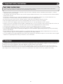 2
2
-
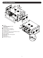 3
3
-
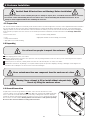 4
4
-
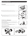 5
5
-
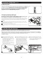 6
6
-
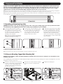 7
7
-
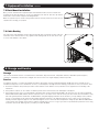 8
8
-
 9
9
-
 10
10
-
 11
11
-
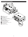 12
12
-
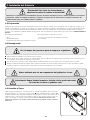 13
13
-
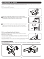 14
14
-
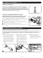 15
15
-
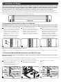 16
16
-
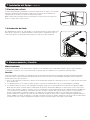 17
17
-
 18
18
-
 19
19
-
 20
20
-
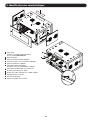 21
21
-
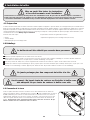 22
22
-
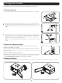 23
23
-
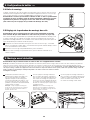 24
24
-
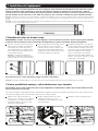 25
25
-
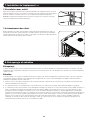 26
26
-
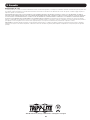 27
27
-
 28
28
-
 29
29
-
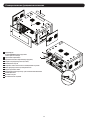 30
30
-
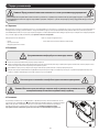 31
31
-
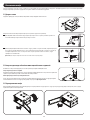 32
32
-
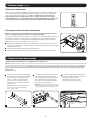 33
33
-
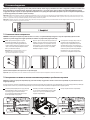 34
34
-
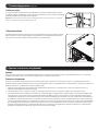 35
35
-
 36
36


Tripp Lite SRW6UDPVRT & SRW6UDPGVRT El manual del propietario
- Tipo
- El manual del propietario
- Este manual también es adecuado para
en otros idiomas
Artículos relacionados
-
Tripp Lite SRW9UDPVRT & SRW9UDPGVRT El manual del propietario
-
-
-
-
-
-
Tripp Lite SRW12UHD & SRW18UHD Wall-Mounted SmartRack Enclosure El manual del propietario
-
-
-