Kenmore 580.73093 El manual del propietario
- Tipo
- El manual del propietario

Owner's Manual
Manual del Propietario
®
THROUGH-THE-WALLAIRCONDITIONER
ACONDICIONADODEAIREA TRAVESDEPARED
Model, Modelo 580.73093 ,580.73104 ,580.77128 580.73144
Sears, Roebuck and Co., Hoffman Estates, IL 60179 U.S.A.
www.sears.com

TABLE OF CONTENTS ........................ 2
WARRANTY .............................................. 2
SAFETY ..................................................... 3
Important Safety Instructions...................... 3
ELECTRICAL REQUIREMENTS .......4
INSTALLATION ........................................ 5
InstaLlationRequirements ......................... 5
Installation................................................ 6
Procedure A ............................................. 7
Procedure B ............................................. 9
Procedure C ........................................... 11
OPERATION ........................................... 12
How and Why ......................................... 12
Normal Sounds ...................................... 12
Capacity and Running Time ................... 12
Features ................................................. 13
Using the Air Conditioner ....................... 13
Air Conditioner Features ........................ 14
MAINTENANCE .....................................16
Air Filter Cleaning ................................... 16
Air Conditioner Cleaning ........................ 16
How to Remove the Front Grille............. 16
How to Replace the Front Grille ............. 16
TROUBLESHOOTING .........................17
Before Calling for Service ...................... 17
ESPAI_IOL ................................................18
MASTER PROTECTION
AGREEMENTS ......................................35
SERVICE NUMBERS ............BackCover
FULL ONE YEAR WARRANTY ON
THROUGH-THE-WALL AIR CONDITIONER
For one year from the date of purchase, when this
air conditioner is operated and maintained for
normal room cooling according to instructions in this
owner's manual, Sears will repair this air
conditioner, free of charge, if defective in material or
workmanship.
WARRANTY SERVICE IS AVAILABLE BY
CONTACTING SEARS SERVICE AT
1-800-4-MY-HOME ®.
This warranty applies only while this product is in
use in the United States.
This warranty gives you specific legal rights, and
you may also have other rights which vary from
state to state.
Sears, Roebuck and Co., D/817WA,
Hoffman Estates, IL 60179 U.S.A.
-2-

IMPORTANT SAFETY INSTRUCTIONS
The safety instructions below will tell you how to use your room air conditioner to avoid harm to yourself or
damage to your ROOM AIR CONDITIONER.
FOR YOUR SAFETY
Do not store or use gasoline or other flammable
vapors and liquids in the vicinity of this or any other
appliance. Read product labels for flammability and
other warnings.
PREVENT ACCIDENTS
To reduce the risk of fire, electrical shock, or injury
to persons when using your air conditioner, follow
basic precautions, including the following:
• Be sure the electrical service is adequate for the
model you have chosen.
• If the air conditioner is to be installed in a window,
you will probably want to clean both sides of the
glass first. If the window is a triple-track type with a
screen panel included, you may want to remove
the screen completely before installation.
• Be sure the air conditioner has been securely and
correctly installed according to the instructions in
this manual.
Save this manual and installation instructions for
possible future use in removing or reinstalling this
unit.
• Use gloves when handling the air conditioner.
Be careful to avoid cuts from sharp metal fins on
front and rear coils.
ELECTRICAL INFORMATION
The complete electrical rating of your new room air
conditioner isstated on the serial plate. Refer tothe
rating when checking the electrical requirements.
• Be sure the air conditioner is properly grounded.
To minimize shock and fire hazards, proper
grounding is important. The power cord is
equipped with a three-prong grounding plug for
protection against shock hazards.
• Your air conditioner must be plugged into a
properly grounded wall receptacle. If the wall
receptacle you intend to use is not adequately
grounded or protected by a time delay fuse or
circuit breaker, have a qualified electrician install
the proper receptacle.
• Do not run air conditioner with packing sheet of
the back of the sleeve, and packing corner and
blue tape of the air conditioner. This could result in
mechanical damage within the air conditioner.
• Do not use an extension cord or an adapter
plug.
_ Avoid fire hazard or electric shock.
Do not use an extension cord or an adapter plug.
Do not remove any prong from the power cord.
Grounding type
Do not under any
circumstances cut,
remove, or bypass
the grounding prong
,-: from this plug.
P°Wwe_S_-p_lYng°rd
grounding plug
/
ENERGY SAVING IDEAS
• The capacity of the room air conditioner must fit
the room size for efficient and satisfactory
operation.
• Install the room air conditioner on the shady side
of your home. A window that faces noah is best
because it is shaded most of the day.
• Do not block air flow inside with blinds, curtains, or
furniture; or outside with shrubs, enclosures, or
other buildings.
• Close the floor and wall registers and the fireplace
damper so cool air does not escape up the
chimney and into the duct work.
• Keep blinds and drapes in other windows closed
during the sunniest part of the day.
• Clean the air filter as recommended in the
MAINTENANCE section of this manual.
• Proper insulation and weather stripping in your
home will help keep warm air out and cool air in.
• External house shading with trees, plants or
awnings will help reduce the air conditioner's work
load.
• Operate heat producing appliances such as
ranges, washers, dryers, and dishwashers during
the coolest part of the day.
-3-

OBSERVE ALL LOCAL CODES AND
ORDINANCES.
DO NOT, UNDER ANY CIRCUMSTANCES,
REMOVE THE POWER SUPPLY CORD
GROUND PRONG.
ELECTRICAL GROUND IS REQUIRED ON
THIS APPLIANCE.
A 208/230-volt and 115-volt 60 Hz, AC only,
15A fused and properly grounded electrical
supply is required. A time delay fuse or time
delay circuit breaker is recommended. Use a
dedicated circuit, serving only this appliance.
DO NOT USE AN EXTENSION CORD.
RECOMMENDED GROUNDING METHOD
For your personal safety, this appliance must
be grounded. This appliance has a power
supply cord with a 3-prong grounding plug. To
minimize possible shock hazard, the cord must
be plugged into a mating grounding type wall
receptacle and grounded in accordance with
the National Electrical Code (ANSI/NFPA 70)
latest edition and all local codes and
ordinances. If a mating wall receptacle is not
available, it is the personal responsibility and
obligation of the customer to have a properly
grounded 3-prong wall receptacle installed by a
qualified electrician.
_WARNING
Electrical Shock Hazard
Plug intoa grounded 3 prong outlet.
Do not remove ground prong.
Do not use an adapter.
Do not use an extension cord.
Failure to follow these instructions can result
in death, fire, or electrical shock.
Ground
prong
grounding
3-prong type wall
grounding _
plug _ receptacle
Power_
supply
cord
-4-

INSTALLATION REQUIREMENTS
If you use an existing wall sleeve, you should
measure its dimensions.
Install the new air conditioner according to these
installation instructions to achieve the best
performance. All wall sleeves used to mount the
new air conditioner must be in good structural
condition and have a rear grille to securely attach
the new air conditioner. (FIG. 1)
With the Kenmore folding sleeve, you can
maintain the best performance ofthe new air
conditioner,
19_V32"
(499 mm) 24-21/32''
[626 mm)
14.13/32"
(366mm}
8"(458mm)
Air Conditioner FIG. 1
ELECTRICAL SERVICE
Check your available electrical service. The power
supply available must be the same as that shown
on the unit nameplate (found on left side of cabinet).
All models are equipped with a 3-prong service plug
to provide proper service and safe positive
grounding. Do not change plug in any way. Do not
use an adapter plug. If your present wall outlet does
not match your plug, call a qualified electrician to
make the necessary corrections. SAVE CARTON
for storage and this OWNER'S MANUAL for future
reference. The carton is the best way to store unit
during winter or when not in use.
INSTALLATION HARDWARE
2 Sizeoptions
ITEM NAMEOF PARTS QITy
PLASTIC GRILLE 1
_) HORIZONTAL INSULATION STRIPS 2
AROUND INSULATION STRIPS 2
SUPPORT BLOCK 2
_) BAFFLE I
(_) TRIM FRAME 2
(_ SHIM 2
_) PLASTICNUTSANDWASHERSCREWS 4
To avoid risk of personal injury, property damage,
or product damage due to the weightof this
device and sharp edgesthat may be exposed:
Air conditioners covered in this manual pose an
excessiveweight hazard.Two ormore people
are needed to move and installthe unit.
To prevent injury or strain, use proper lifting and
carrying techniques when moving unit.
• Carefullyinspect location whereair conditioner
will be installed.Be sureit will support the weight
ofthe unitover an extendedpedod oftime.
• Handle air conditioner with care. Wear
protective gloves whenever lifting or carrying the
unit. AVOID the sharp metal fins of front and
rear coils.
• Make sure air conditioner does notfall during
installation.
REQUIRED TOOLS:
• Tight Fitting gloves
• Standard screwdriver
Phillips screwdriver
Pliers
Sharp knife
• 3/8-inch open end
wrench or adjustable
wrench
• 1/4-inch hex socket
and ratchet
• Tape measure
• Electric drill
• 1/4-inch drill bit
-5-

INSTALLATION
We strongly recommend the removal of the
old wall sleeve and the installationof a new
Kenmore folding Wall Sleeve.
If you decide to keepthe existing wall sleeve,
you have to redirect the louvers at the back of the
wall sleeve illustration. The use of pliers is
recommended. If you DO NOT redirect, yourun
the risk of poor performance or product failure.
This is notcovered under the terms of the
Kenmore warranty.
• Pick a location which will allow the conditioned air to
blow into the area you want. Good installation with
special attention to the proper position of the unit will
lessen the chance that service will be needed.
• Assemble the folding sleeve for this unit according to
the instructions provided.
ITEMS IN INSTALLATION HARDWARE
Youmaynotneedallpartsin thekit,Discardunused
_arts
_e
Horizontal Insulation Strips
Around Insulation Strips
Support Block
Baffle
Shim
Trim Frame
Washer Screw
Nuts(Plastic)
ITEM (inches)
283/4 X 161/2
13/8X 5/8X 273/16
13/8 X 13/8 x 273/16
13/8x 3/4x 611/2
13/8 x 13/8X 611/2
13j4 x 13/8x 45/16
14 x 41/2 X %
13x 1 X3/4
Qty.
1
1
1
1
1
2
1
2
2
4
4
HOW TO INSTALL
a identify the existing wall sleeve before installing
the unit from the listed below.
Brand Wall Sleeve Dimensions (inches
Width Height Depth
White-WestinghousE
Frigidaire 25-1/2 15-1/4 16, 17-1/2
Carrier (52F series) or 22
General Electric
iHotpoint 26 15-5/8 16-7/8
Whirlpool 25-7/8 16-1/2 17-1/8
or 23
Fedders/Emerson 27 16-3/4 16-3/4
or 19-3/4
Sears/Kenmore 25-7/8 15-17/32 16-23/32
Emerson/Fedders 26-3/4 15-3/4 15
Carrier (51S Series) 25-3/4 16-7/8 18-5/8
Friedrich 27 16-3/4 16-3/4
NOTE: All wall sleeves used to mount the new Air
Conditioner must be in sound structural condition
and have a rear grille that securely attaches to
sleeve, or rear flange that serves as a stop for the
Air Conditioner,
I_'_ Remove old air conditioner from existing wall
sleeve.
i_ Clean the interiorof an existing sleeve.
(Do not disturb seals.)
L_Wall sleeve must be securely fastened in wall
before installing the air conditioner. Use the
nails or screws through sleeve into wall, if
needed. Repaint sleeve if needed.
I_ Prepare the wall sleeve for installation of the
unit. If you plan to use your existing wall sleeve,
and it is not Kenmore, use procedure B or C
below.
Procedure
A
B
Brand
Sears/Kenmore
White-Westinghouse
Frigidaire Carrier
(52F series)
General Electric
/Hotpoint
Whirlpool
Carrier (51S series)
Fedders/Emerson
Depth(inches
16-23/32
16, 17-1/2
or 22
16-7/8
C
Emerson/Fedders
Friedrich
r_ Install unit intowall sleeve.
new
CAUTION: When installation is completed,
replacement unit MUST have a rearward slope as
shown.
UNIT Wall Sleeve
17-1/8 or 23
18-6/8
16-3/4
or 19-3/4
15
16-3/4
FRONI_ T-.............
1/4't U] ............
FIG. 2
-6-

PROCEDURE A
n If you are using a new Kenmore folding sleeve
with your unit, skip to step 3, Otherwise, install
the plastic grille from the kit. Cut the plastic
grille to 25-1/2" wide and 15-1/4" high. Place
the plastic grille to the inside of the wall sleeve
at the rear flange.
FIG. 3
_'_ Fasten the 4 washer screws to secure the grille
to the wall sleeve. If you need plastic nuts to
mount plastic grille to the inside of the wall
sleeve, there are plastic nuts in the installation
kit. The nuts are installed from the inside of the
sleeve and are pressed intothe square holes of
the rear flanges.
or
FIG. 4
_]_ Install the new unit into the wall sleeve.
_---! To assemble trim, snap the tab of each piece
into the slot of the other piece as shown below.
Slide trim over the front of the air conditioner
until trim is flush with sleeve as shown below.
I
I
Trim(2 ea)
Wall
FIG. 6
_J Remove the backing from the Horizontal
Insulation strip 13/ex 3/8x 273_1sand attach that
to the inside bottom of the sJeeve as shown
below. Remove the backing from the Around
Insulation strip 13_8x 3_4x 611/2and attach that
to the inside front of the sleeve as shown
below.
FIG. 5
• Airconditioners covered inthismanualpose
an excessive weighthazard. Two or more
peopleare neededtomoveand installthe unit.
To preventin uryorstrain,useproperlifting
and carryng technques when movng unt.
• When handlingthe air conditioner,be careful
to avoidcutsfrom sharpmetalfinson front and
rear coils.
• Make sureair conditionerdoesnotfall during
removal.
-7-

PROCEDURE B
L1 Redirect the louvers at the back of the wall
sleeve to60 ° angle as shown in the FIG 7. The
use of pliers is recommended.
7 5,16"
\\k\\\\\\\\\\\\\\\\_
Rear Louvers
(Top View)
/_0 _
FIG. 7
_lf the wall sleeve already has a rear grille, skip
to step 4. If the wall sleeve does not have a rear
grille or Iouvered panel, install the plastic grille
from the kit. Cut the plastic grille to 25-1/2" wide
and 15-1/4" high. Place the plastic grille to the
inside of the wall sleeve at the rear flange.
Place the plastic grille
FIG. 8
_J_ Fasten the 4 washer screws to secure the grille
to the wall sleeve. If you need plastic nuts to
mount plastic grille to the inside of the wall
sleeve, there are plastic nuts in the installation
kit. The nuts are installed from the inside of the
sleeve and are pressed into the square holes of
the rear flanges.
]
Fasten the screws
FIG. 9
L_I Remove the backing from the Horizontal
Insolation strip 13/8x 5s8x 273/16and attach that
to the inside bottom of the sleeve as shown
below. Remove the backing from the Around
Insulation strip 13/8x 3/4x 611/2and attach that to
the inside front ol the sleeve as shown below.
FIG. lC
_"_ If the depth of your existing wall sleeve is less
than or equal to 18", skip to step 7. Otherwise,
cut the baffles and the support blocks according
to length "A" in the table below.
Depth"D" ofthe existing Length"A"
wallsleeve (inches) (inches)
18 <D<_18-% 3/4
18-%<D<_19-3/4 1-3/4
19-_/4<D_<22 4
Baffle
_._ FIG. 11
r_ Remove the backing from the support blocks
and attach them to the inside of the wall sleeve
as shown FIG 8. Slide the baffle into slots of the
support blocks.
Wall
Wall
Sleeve
_'_ Install the new unit into the wall sleeve.
FIG. 12
-8-

PROCEDURE B
_lTo assembletrim,snapthetabofeachpiece
intotheslotoftheotherpieceas shownbelow.
Slide trimoverthefrontoftheairconditioner
until trim is flushwithsleeve as shown below.
Wall
FIG. 13
• Airconditioners coveredin this manual pose
anexcessive weighthazard. Two or more
peopleare neededtomoveand installtheunit.
To preventinjuryor strain,use properlifting
and carryingtechniqueswhen movingunit.
• Whenhandlingthe air conditioner,be careful
toavoidcutsfrom sharpmetalfins on front and
rear coils.
• Make sureair conditionerdoesnotfall during
removal.
-9-

PROCEDURE C
_1 Redirect the louvers at the back of the wall
sleeve to 60° angle as shown in the FIG 14.
The use of pliers is recommended.
6o_z_
• 13/16"
\\\\\\\\\\\\\\\\\\\_
Rear Louvers
(Top View)
/_0 °
FIG. 14
_lf the wall sleeve already has a rear grille, skip
to step 4. If the wall sleeve does not have a rear
grille or Iouvered panel, install the plastic grille
from the kit. Cut the plastic grille to 26-1/2" wide
and 15-1/2" high. Place the plastic grille to the
inside of the wall sleeve at the rear flange.
Place the plastic grille
FIG. 15
_1 Fasten the 4 washer screws to secure the grille
to the wall sleeve. If you need plastic nuts to
mount plastic grille to the inside of the wall
sleeve, there are plastic nuts in the installation
kit. The nuts are installed from the inside of the
sleeve and are pressed into the square holes of
the rear flanges.
_.1._Remove the backing from the Horizontal
Insulation strip 13/8x 13/8x 273116and attach that
to the inside bottom of the sleeve as shown
below. Remove the backing from the Around
Insulation strip 13/8x 13/8x 61_/2and attach that
to the inside front of the sleeve as shown below.
FIG. 17
_-"_ If the depth of your existing sleeve is less than
or equal to 18", skip to step 7. Otherwise, cut
the baffles and the support blocks according to
Length "A" in the table below.
Depth"D" ofthe existing Length"A"
wallsleeve (inches) (inches)
18 <D_<18-% 3/4
t8-% <D_<19-3/4 1-3/4
19-3/4<D_<22 4
A_
- upport
Block
4 Baffle
A.i FIG. 18
r_ Remove the backing from the support blocks
and attach them to the inside of the wall sleeve
as shown FIG 19. Slide the baffle into slots of
the support blocks
Nail _ ;,._.
|, ,_.
Vail --
eve _ : ,
=
{
÷,
Support"4:
_"_i_ BLOCK
!N i:
' FIG. 19
Fasten the screws FIG. 16
-10-

PROCEDURE C
Remove the backing from the 13" shim strips
and attach them as shown below in Fig. 21,
The higher portion of shim is to be placed in
front of the rib on the base of wall sleeve.
,h,ghII--
lI 3/4" High
FIG. 20
FIG, 21
ir_ install the new unit into the wall sleeve
_To assemble trim, snap the tab of each piece
into the slot of the other piece as shown below.
Slide trim over the front of the air conditioner
until trim is flush with sleeve as shown below.
I
Trim (2 ea)
Wall
FIG. 22
• Air conditioners coveredin this manualpose
an excessive weight hazard. Two ormore
people are needed to move and install the unit.
To prevent injury or strain, use proper lifting
and carrying techniques when moving unit.
• When handling the air conditioner, be careful
to avoid cuts from sharp metal fins on front and
rear coils.
Make sure air conditioner does not fall during
removal.
-11 -

HOW AND WHY
Your room air conditioner provides the following
functions to make hot weather living more
comfortable:
• Cools and circulates room air.
• Lowers humidity by removing excess moisture.
• Filters out summertime dust, dirt, and some
airborne impurities.
The air conditioner performs these functions by
drawing room air through a filter which traps dust
and dirt particles. The air then passes over a
cooling coil which refrigerates the air and removes
excess moisture. The same air is then returned to
the room- cooler, drier, and cleaner. Moisture
removed from the room air is carried to the outside
and evaporated.
Your air conditioner is designed to be easy to
operate and to provide plenty of cooling power.
NORMAL SOUNDS FIG.23
Aside from the regular fan motor and compressor
sounds coming from your air conditioner, you will
once in a while hear a pinging sound. This is the
result of moisture being picked up from the air in the
room and thrown against the air conditioner's fan.
This is normal and should not be cause for concern.
Also, do not be alarmed if you hear a slight hissing or
gurgling sound coming from your air conditioner after
it is off. These are normal coolant noises.
CAPACITY AND RUNNING TIME
Proper unitsize is important in deciding the desired
comfort for the area you want to cool. The proper
size isdetermined by the number of square feet in
the area to be cooled.
Whenever the heat or humidity load is above normal
the air conditioner must run longer and more often
to keep the desired temperature you have selected.
Under heavy heat load conditions the air conditioner
may need to run constantly to keep the temperature
you want.
At times using the MED FAN setting to circulate the
room air may make it comfortable even though you
do not have the air conditioner set to cool the air.
This will decrease your cost of use.
Fan
Unit Vibration
The unitmay vibrate
and make noise
because of poor wall
or window
construction.
You may hear air
movement from the
fan.
Compressor
The modern high
efficiency compressor
may have a high pitched
humor pulsating noise
that cycles on and off.
Con
You may hear
droplets of water
hitting the condenser,
causing a pinging or
clicking sound.
FIG. 23
-12-

FEATURES
THE UNIT
1 5 736284
1. CABINET
2. HORIZONTAL AIR DEFLECTOR
(Vertical Louver)
3. VERTICAL AIR DEFLECTOR
(Horizontal Louver)
4. AIR DISCHARGE
5. FRONT GRILLE
6. INLET GRILLE (Air Intake)
7. AIR FILTER
8. VENT CONTROL
FIG. 24
USING THE AIR CONDITIONER
_To reduce the risk of fire, electric
shock, or injury to persons, read the important
SAFETY instructions section before operating this
appliance.
To begin operating the air conditioner after
installation, follow these steps:
1. Plug in the air conditioner. (To prevent electrical
hazards, do not use an extension cord or an
adapter plug.)
2. Set the TEMP control to the coolest setting.
3. Set the MODE control at the highest COOL level.
4. Adjust the louvers for comfortable air flow.
5. Once the room has cooled, adjust the TEMP and
MODE control to the setting you find most
comfortable.
NOTE : If the air conditioner is turned off, wait 3
minutes before restarting. This allows pressure
inside the compressor to equalize. Failure to wait 3
minutes before restarting may cause inefficient
operation.
If you move the TEMP control to a warmer, then
immediately back to a cooler setting, the unit will
shut off. Wait 3 minutes before restarting.
Refer to the AIR CONDITIONER FEATURES
section for other settings.
VENT CONTROL
The Vent Control allows the air conditioner to either
recimulate inside air (CLOSE) or exhaust air to the
outside (OPEN). (FIG. 25)
• The CLOSE position is used when maximum
cooling is desired. It may also be used for air
recimulation without cooling when the air
conditioner isset in the FAN position.
• The OPEN position removes stale air from the
room and exhausts it to the outside. Fresh air is
drawn into the room through your home's normal
air passages.
• The OPEN or CLOSE position can be used with
any fan selection.
PULL OPEN / PUSH CLOSE
FIG. 25
-13-

DISPLAY
Cool •
Energy •
Saver
Fan •
Timer • TEMP O
(-TIMER
- SHUT-OFFTIME
• Youwillusuallyuseshut-offtimewhileyousleep.
• Withunitrunning,useTLmertoset numberofhours
untilshut-off.
• Foryoursleepingcomfort,onceTime isset,the
Temperaturesettingwillraise2°F after30 rain.,
and 2°F afteranother30 min.
• EverytimeyoupushTimerbutton,itadvancesthe
Timersettingas follows:1 Hour_ 2 Hours.....
12 Hoursmaximum.
- START TIME
• With unit notrunning, use Timer to set numberof
hours before until starts.
• Everytime you pushTimer button, it advancesthe
Timer settingas follows: 1 Hour-, 2 Hours -, •.....
12 Hours maximum.
REMOTE CONTROL SIGNAL
RECEIVER
JRE SETTING
• Usethisbuttontoautomaticallycontrolthe
temperatureoftheroom.
Thetemperaturecanbesetwithina range
of60°F to86°F byincrementsofI°F.
POWER
•To turntheairconditionerON, pushthis
button.
To rumtheairconditionerOFF, pushthe
buttonagain.
• Thisbuttontakespriorityoveranyother
button.
•Whenyoufirst turniton,the unitisin
coolmode,Highfanspeed,Temperature
settingat 72°F.
-- FAN SPEED
•Everytimeyoupushthis button,it
advancesthesettingas follows:
{High-_Low-_Med-_High}
MODE
- Everytimeyou pushthisbutton,itwillshiftamongCOOL, ENERGY SAVER and FAN.
- ENERGY SAVER:
• The fan stopswhenthe compressorstopscooling. Approximatelyevery3 minutesthefan willtumonand
theunitwillchecktheroomair todetermineifcoolingisneeded.
_d after an electrical power failure, theunit willbegin to runat its lastsetting. 1
-14-

HORIZONTAL AIR-DIRECTION
ADJUSTMENT
• The horizontal air direction is adjusted by moving
vertical louver.
• The vertical louver control levers are located in the
right and left side of the air discharge.
FIG. 26
VERTICAL AIR-DIRECTION ADJUSTMENT
• The vertical air direCtion is adjusted by moving the
horizontal louvers,
FIG. 27
-15-

AIR FILTER CLEANING
The Air Filter will become dirty as it removes dust
from the inside air. It should be washed at least
every 2 weeks. If the Air Filter remains full of dust,
the air flow will decrease and the cooling capacity
will be reduced, possibly damaging the unit.
• Pull the inlet grille forward and pull out the air filter.
(FIG. 28)
• Wash the Air Filter under the faucet with warm
water. Be sure to shake off all the water before
replacing the filter. (FIG. 29)
FIG. 28 FIG. 29
AIR CONDITIONER CLEANING
Clean the front grille and inlet grille by wiping with a
cloth dampened in a mild detergent solution.
The cabinet may be washed with mild soap or
detergent and lukewarm water, then polished with
liquid appliance wax.
To ensure continued peak efficiency, the condenser
coils (outdoor side of the unit) should be checked
periodically and cleaned if they become clogged
with soot or dirt from the atmosphere. Brush or
vacuum exterior coils to remove debris from fins.
_FIG. 30
HOW TO REMOVE THE FRONT
GRILLE
• Open the inlet grille.
• Remove the screw securing the Front Grille.
• Push the grille up from the bottom and pull the top
of the grille away from the case to lift the top tabs
out of their slots.
FIG. 31
HOW TO REPLACE THE
FRONT GRILLE
Attach the front grille to the cabinet by inserting the
tabs on the grille into the slots on the front of the
cabinet. Push the grille in until it snaps into place.
FIG. 32
-16-

BEFORE CALLING FOR SERVICE
Check the following listto be sure a service call is really necessary. A quick reference to this manual may
help you avoid an unneeded service call.
THE AIR CONDITIONER WILL NOT OPERATE
Check if... Then...
Wall plug disconnected.
House fuse blown or circuit breaker tdpped.
Power is OFF.
Unitwasturnedoffandthenontooquickly.
TEMPControlsetwannerthanroomtemperature.
Push plug firmly into walloutlet.
Replace fuse withtime delay type or reset circuit breaker.
Push the powerbutton,
Set unit off and wait 3 minutes before restarting,
Set TEMP Control to a lower number,
AIR FROM UNIT DOES NOT FEEL COLD ENOUGH.
Check if... Then...
FANSPEEDsetatLOW.
TEMPControlsettoowarm.
Roomtemperaturebelow70°F(21°C).
Temperaturesensingtubetouchingevaporatorcoil,
locatedbehindfrontgrille.
PushFANSPEEDbuttontosetatHL
SetTEMPControlto alowertemperature.
Coolingmaynotoccuruntilroomtemperaturerisesabove70°F(21°C),
Straightentubeawayfromevaporatorcoil.
THEAIRCONDn'IONERCOOUNG,BUTROOMISTOOWARM-ICEFORMINGONCOOUNGCOILBEHINDINLETGRILLE.
Check if... Then...
Outdoortemperaturebelow70°F(21°C). Todefrostthe coil,settheMODEtoFAN,FANspeedtoHigh.
Airfiltermaybedi_. Cleanairfilter.RefertoMaintenancesectionofowner'smanual.
TEMPControlsettoolow. Todefrostthecoil,settheMODEtoCool,Fanspeedtohigh,andthe
Tempcontroltoa highertemperature.
THEAIRCONDITIONERCOOUNG,BUTROOMISTOOWARM
Check if...
Dirtyairfilter- airrestricted.
TEMPControlsettoowarm.
Frontofunitisblockedbydrapes,blinds,furniture,etc.
Afrdistributieais restricted.
Doors,windows,registers,etc.open.Coldairescapes.
Unitrecentlyturnedonin hotream.
Then.,.
Cleanairfiltar.RefertoMaintenancesectionofowner'smanual.
SetTEMPControltoalowertemperature.
Clearblockageinfrontofunit
Close doors, windows,recjistere,etc.
Allowadditionaltimetoremovestoredheatfromwalls,ceiling,floor,andfurniture.
THE AIR CONDITIONER TURNS ON AND OFF RAPIDLY,
Check if.., Then...
! Outsidetemperatureisextramalyhot I SetFANSPEEDonHItobringairpastcoolingcoilsfaster. I
NOISE WHEN UNIT IS COOLING.
Check If... Then,..
I Soundoffanhittingwater- fromthemoistureremovalsystem.ThisisnormalwhenhumidityishighClosedoom,windows,andregistera
Windowvibration-poornstallatJon. Referoinstalfaioninstructionsorcheckwithnstaler.
WATER DRIPPING INSIDE ROOM WHEN UNIT IS COOLING.
Check if,.. Then...
t Theairoonditiooerisimproperlyinstalled. I 331tairconditionerslightlytotheoutaidetoallowwaterdrainage.Referto
installationnstructionsor checkwithinstaller.
WATER DRIPPING OUTSIDE WHEN UNIT IS COOLING.
Check if... Then...
I Theunitisremovinglargequantitiesofmoisture
fromhumidroom. I Thisisoormaiduringexcessivelyhureiddays" t
-17-

|NDICE ......................................................18
GARANT[A ..............................................18
SEGURIDAD ...........................................19
Instruccionesimportantesde seguridad .-.19
REQUISITOS ELI_CTRICOS .............2o
INSTALAClON ........................................21
Requisitos de instalaci6n ....................... 21
Instalacibn .............................................. 22
Procedimiento A..................................... 23
Procedimiento B..................................... 24
Procedimiento C..................................... 26
FUNCIONAMIENTO ............................. 28
Cbmo y pot que...................................... 28
Sonidos normales .................................. 28
Capacidady tiempode funcionamiento ....28
Caracterfsticas ....................................... 29
Uso del aparato de aire acondicionado,,-,.29
Caracterfsticas del aparato de aire
acondicionado ........................................ 30
MANTENIMIENTO ................................ 32
Limpieza del filtro de aire ....................... 32
Limpieza del aparato de aire
acondicionado ........................................ 32
C6mo extraer la rejilta frontal ................. 32
C6mo volver a colocar la rejitlafrontal ...32
RESOLUCI(_N DE PROBLEMAS....33
Antes de Ilamar al servicio t_cnico .........33
ACUERDOS DE PROTECCION
ESPECIALIZADA ..................................35
NUMEROS DE SERVIClO
TECNICO .................................. Contraportada
GARANTIAC0MPLETA DE UN AN0 DEL
APARAT0DE AIREACONDICl0NADO DE
PARED
Duranteunafio,acontarapartirdela fechadecompra,cuando
esteaparatodeaireacondicionadofuncioneparael enfnamiento
normaldeunahabitaci6nyrecibamantenimiento,tedoello
seg0nlasinstruccionesde esteManualdelpropietario,Sears
reparar_esteaparatodeaireacondicionado,deformagratuita,si
tuvieraalg0ndefectodefabricaci6nomateriales,
EL SERVIClODEGARANT[APUEDE
CONTACTARSEENELSERVIClO DEATENCI6N
AL CLIENTEDESEARS EN EL1-800-4-MY-HOME®,
Estagarantfaseaplicas61oduranteelusodeestepreductoen
losEstadosUnidos.
Estagarantiale concedederechoslegalesespecificosy puede
queustedtengaotrosderechosadicionalesquevarianseg0nel
estado.
Sears,RoebuckandCo., D/817WA,Hoffman
Estates,IL 60179 EE.UU.
-18-

INSTRUCCIONES IMPORTANTES DE SEGURIDAD
Las instrucciones de seguriclad que se indican abajo le dir_.n come utilizar su aparato de aire acondicionado
para evitar dafios a si mismo y daSos a su APARATO DE AIRE ACONDIClONADO.
PARA SU SEGURIDAD
No almacone ni utilicegasolina ni otros liquidos ni gases
inflamables cerca de este uotro electredom6stieo. Lea
las etiquetas de los productos para oonocer su
inflamabilidad y otras advertencias.
EVITAR ACCIDENTES
Parareducirel riesgode inoendio,electrocuci6noheridasa
personasal utilizarsuaparatode aireacondicionado,siga
las precaucionesbasicas,incluyendolas siguientes:
• Aseg0resede queel servicioelectricoesadecuadopara el
modeloqueha escogido.
• Si elaire acondicionadova a instalarseen unaventana,
serfaconvenientequelimpiara primeroamboslades del
oristal.Si la ventanatienetresguias de deslizamiento,con
un panelpantallaincluido, puedeque deseeextraer
comple'_mentela pantallaantesde la instalaci6n.
• AsegSresede queel aparatode aireacondicionadose ha
instalaclode modeseguroy correctosegSnlas
instruccionesen esteManual.Guardeestemanualy las
instruccionesde instalacionpara suposibleusefuturepara
extraero volvera instalarestauniclad.
• Utiliceguantescuandomanejeel aparatode aire
acondicionado.Presteatenci6npara evitarcortesde las
afiladasaletasde metalen las bobinasfrontaly posterior.
_ INFORMACI6N ELI_CTRICA
Elvalornominalel_otricocompletede sunuevoaparatodeaire
acondicionadoseespecificaonsu etiquetaidentificativa.
Consulteel valornominalalcomprobarlosrequisiteselSctricos.
• Asegtiresedequeel aparatode aire acondicionadotiene
unatomacletierraadecuada.Parareduciral minimoel
riesgode electrocuci6ny de incendio,esimportantetener
unatomade tierraadecuada.Elcablede alimentacibnesta
equipadoconun enchufede tres clavijascontomaa tierra
para protegercontra electrocuci6n.
• Su aparatodeaireacondicionadodebeestarenchufadoa
unenchufedeparedcon unatomadetierra adecuada.Si
el enchule quequiereutilizarno tieoeunatomade tierra
adecuadao noest_ protegidoperunfusible temporizadoo
un interrupterdecorriente, hagaqueuneleotricista
cualificadoinstaleel enchufeapropiado.
• No hagafuncionarelaparatode aireaconclicionadocon la
I_minade embalajeen la parleposteriordelalojamientoo
con laointaazuly las esquinerasdelaparatode aire
acondicionado.Esto podriatener comeconsecuenciala
produccionde daSosmecanicosal aparatodeaire
acondioionado.
• NOutilicean cableextensor niun enchufeadaptador.
_ Evitelospeligrosdeincendioodeelectrocuci6n.
Noutilicauncableextensorniunenchufeadaptador.
Noquiteningunaclavijadelcabledealimentaci6n.
Recept&culoen
paredcon toma Nuncacorte, extraiga ni]
de tierra haga unaderivaci6n que /
evite laclavija de toma [
de tierrade este
enchufe, j
IDEAS PARAAHORRAR ENERG|A
• La capacidad del aparatode aire acondicionadodebe
set adecuada al tamafio de la habitaci6n para un
funcionamiento eficaz y satisfaetorio.
• Instale el aparato de aireacondicionado en el lade de su
hogar a la sombra. Una ventana que miraal norte es la
mejor porque se encuentra a lasembra la mayor porte
del dfa.
• No bloquee el#lujodel aire en el interior con persianas,
cortinas o muebles, ni en elexterior con arbustos,
cercas u otros edificios.
• Cierre las aperturas en sueloy ventanasy el tire de la
chimenea para que el aire frfo no salga per la ohimenea
ni per los conductos.
• Mantenga eerradaslas persianasy cortinas de otras
ventanas durante la parte rodssoleada del dia.
• Limpieel filtro de aire seg_n se recomienda en la
secci6n de MANTENIMIENTO de este manual.
• El aislamiento aclecuado y lapreparaci6n de suhogar
para las condiciones atmosf_.rieasmantendr_n el aire
caliente en el exterior y el aire fifo en el interior.
• La existencia de sombra en el exteriorde la casa con
_rboles, plantas o toldos reduce la carga de trabajo del
aparato de aire acondicionado.
• Haga funcionar los electrodom_sticos que produzcan
calor, come cocinas, lavadoras, secadoras y lavavajillas,
durante la parte m_s fria del dfa.
-19-

CUMPLA TODAS LAS NORMAS Y CODIGOS
LOCALES
NUNCA ELIMINE LA CLAVIJA DE TOMA DE
TIERRA DEL CABLE DE ALIMENTACION.
LA TOMA DE TIERRA ELECTRICA EN ESTE
ELECTRODOMI_STICO ES NECESARIA.
Se necesita una alimentaci6n electrica de
208/230-volt y 115-volt 60 Hz, s6io de CA, con
fusible de 15A y con una toma de tierra
adecuada. Se recomienda tambi_n que haya
un fusible o interruptor temporizado. Utilice un
circuito electrico dedicado s61oa este aparato.
NO UTILICE UN CABLE EXTENSOR.
MI=TODO RECOMENDADO DE TOMA DE
TIERRA
Para su seguridad personal, este aparato debe
tener una toma de tierra. Este aparato tiene un
cable de alimentaci6n con un enchufe de 3
clavijas, una de elias para la toma de tierra.
Para reducir a[ m{nimo el riesgo de
electrocuci6n, el cable debe estar enchufado
en un recept&culo de pared con toma de tierra
de acuerdo con la 61tima edici6n del C6digo
nacional sobre electricidad (ANSI/NFPA 70) y
siguiendo todas las normas y directrices
locales. Si no estd disponible un recept&culo
de pared, es responsabilidad y obligaci6n
personal del cliente hacer que un electricista
cualificado instale un recept_.culo en la pared
de 3 clavijas con una toma de tierra adecuada.
A ADVERTENCIA
Riesgo de electrocuci6n
Enchufe en una toma de 3 clavijas con toma
de tierra. No elimine la clavija de toma de
tierra. No utilice un adaptador.
No utilice un cable extensor.
No seguir estas instrucciones puede tener
como consecuencia la muerte, un incendio o
electrocuci6n.
alimentaci6n con
clavija dotada de
conexi6n a tierra
de 3 terminales.
Toma de corriente
de pared con
conexi6n a tierra.
_rminal de
r conexi6n a tierra.
Bajo ninguna
circunstancia corte, quite o
evite el uso de la conexion
a tierra de esta clavija.
- 20 -

REQUISITOS DE INSTALACION
Si utilizaunalojamientodeparedexistente,debetomarsus
medidas.
Instaleelnuevoaparatodeaireacondicionadoseg0nestas
instruccionesde instalacionparaconseguirel meierrendimiento.
Todoslosalojamientosdepareduti]izadosparamontarel nuevo
aparatodeaireacondicionadodebentenersuestructuraen
buenascondicionesytenerunarejillaposteriorparafijarcon
seguridadel nuevoaparatodeaireacondicionado.(FIG.l)
ConelalojamientoKenmore,puedemantenerelmaximo
rendimientodesunuevoaparatodeaireacondicionado,
Aparatodeaimacondicionado
-t
14.13/32"
ram)
8"(458 ram)
FIG. 1
SERVIClO ELECTRICO
Compruebeelservicioeleotricodisponible.Laalimentaci6n
disponibledebecoincidirconlaque9emuestraenla etiqueta
identificativadelaunidad(queseencoentraenelladeizquierdo
delalojamiento).
Todoslosmodelosestanequipado9conunenchufedesenJicio
de3clavijasconunatomadetierrapositivasegura.No
modifiqueelenchufedeningunamanera.Noutiliceunenchufe
adaptador.Si9utomadecorrienteen laparednocoincideconel
enchufe,flamea unelectricistaoualificadopararealizarlos
cambiosnecesarios.GUARDELACAJAparaelalmacenamiento
yestaGUiADELPROPIETARIOparafuturareferencia.Lacala
eslamejormaneradealmacenarlaunidadduranteelinviemoo
cuandonoseutilice.
EQUlPO DE INSTALAClON
2opcionesdetamaSo
2opcmnesdetama_o(_
AR]ICUL( NOMBREDELASPIEZAS CA_DAD
(_ REJILLADE PL,_STICO 1
<_ TIRAS DE AISLAMIENTO HORIZONTAL 2
(_ TIRAS DE AISLAMIENTO LATERAL 2
(_) BLOQUE DE SOPORTE 2
(_) DEFLECTOR 1
_) BASTIDOR DE REBORDE 2
(_) CALZO PARA AJUSTE 2
(_ TUERCASDEPLASTICOYTORNILLOSDEARANDEI. 4
Paraevitarpeligrodeheridaspersonales,daSosalapropiedade
alproductedebidoalpesodeesteaparatoyalosbordes
afiladosquepoedenestarexpuestes:
•Losaparatosdeaireacondicionadodelosquetrataeste
manualconstituyenunpeligrodepesoexcesivo.Senecesitan
dosomaspersonasparamovereinstalarlaunidad.Paraevitar
heddasoproblemasmusculares,utilicet_cnicasadecuadas
paraelevarydesplazarlaunidad.
•Revisecuidadosamentelaubicaci6ndondeseinstalar_elaparato
deaimacondicionado.AsegOresedequepuedesopoderelpeso
delaunidadduranteunpedododetiempeprolongado.
, Manejeconcuidadoelaparatodeaimacondicionado.Ueve
goantesprotedoressiemprequelevanteodesplacelaunided.
EVITElasaletasafiladasdemetaldelasbobinasfrontaly
posterior.
•Aseg0resedequeelaparatodeaimacondicionadonocaeal
soelodurantelainstalaci6n.
HERRAMIENTASNECESARIAS:
• Guantesajustade_
• Destomilladorestandar
• DestomilladorPhillips
•Cuchilloafllado
, Cintaparamedir
•Llaveajustableodeextreme
abiertode0,96cm(3/8depulgade)
•Llavearticulada
•Uavedecabeza_xagonalde
0,64cm(1/4depulgada)y
trinquete
, Taladroel_rlco
•Brocadetaladrode0,64cm
(1/4depulgada)
-21 -

INSTALACI( N
Serecomiendaencarecidamentelaextracciondelantiguo
alojamientodelaparedylainstalaciondeunalojamiento
plegabledelaparedKenmorenuevo.
Sidecidemantenere!alojamientodeparedexistente,tendr,_
queajustarladirecciondelarejillaenlaporteposteriordela
ilustraci6nde/alojamientodepared.Serecomiendaelusode
tenazas.SiNOajustaladirecci6n,correelriesgodeun
rendimientopobreodefallode/producto.Estehechonoest',
cubiertobajolostenninosdelagarantiadeKENMORE.
• Sidecidemantenerelalojamientodeparedexistente,tendraqueajustarla
direccidedelarejillaenlapadeposteriordelailustracidedelalojamiento
depared.Serecomiendaelusodetenazas.SiNOajustaladireeci6n,
correeldesgodeunrendimientopobreodefallodelprcducto.Estehecho
noest&cubiertobajolosterm/hasdelagarantiadeKENMORE.
• Ensambleelmanguitodeplegarparaestaunidadseg0nlasinstru_ones
dadas.
ARI'iCULOS EN EL EQUIPO DE INSTALACION
Puedequenonecesitetodaslaspartesdelequipode
instalacibn,Tirelaspiezasqueno utilice.
ART{CULO
RejWadepldstico
Tirasdeaislamientohdezontal
TirasdeaiWamientolateral
3,81x2,54x2t0,O_cm(263/4x16V2)
3,5x 1,52x69,03cm(131ex%x273A6)
3,5x3,5x69,03cm(13/sx 13/ax273/16}
3,5x2,03x153,635(13/sx3/4x61V2)
3,5x3,5x 153,035(13/sx1%x61V2)
8,89x3,5x10,94cm(13/4x 13/8x45he)
35,56x11,43xO,33(14x4V_xVa)
33,02x2,54x 2,03(13x1x3A)
61oquedesopode
De6ector
Ca_zopareajusle
Basgdordereborde
Tomillodearandela
Tuercas(plasti¢o)
C( MO INSTALARLO
i_ Identiliqueelalojamientoexiatenteenlaparedantesde
instalarlaunidaddelalistaquesemuestraacoetinuaci6n
Medidasdelalejamientodelapared
Marc3
White-Westinghouse
Frigidaire
Carrier(Serie52F)
GeneralElectrich4otpoint
Whirlpool
Fedders/Emerson
Sears_Y,enmore
Emerson/Fedders
Cartier(Serie 51S)
Fdeddch
Can_
1
1
1
1
!
2
1
2
2
4
4
(pulgadas y cent/metros)
Anchura Altura Profundidad
64,77 38,73 40,64,44,46,55,88
(25-1/2) (15-1/4) (16,17-1/2)
66,04(26) 39,70(16-518 12,87(16-7/8)
65,48(25-7/8)41,91(16-1/2 13,51058,42
(17-1/8o23)
68,58(27) 42,54(16-3/4 42,54o50,16
16-314o19-3h
65,73(25-7/8)39,44(15-17/3212,46(16-23FJ_j
67,94(26-3/4) 40(15-3/4) 38,1 (15)
65,40(25-3/4)42,87(16-7/_ 47,32(18-5/8)
68,58(27) 42,54(16-3/4)42,64(15,3/4)
- 22 -
NOTA:Todoslosalojamientosdeparedutilizadosparamontar
el nuevoaparatodea/reacondicionadodebenestarenbuenas
condicionesestructuratesy tenerunarejillaposteriorqueseuna
conseguridadal alojamientoo unfianceposteriorquesirvade
topealaparatodeaireacondicionado,
_ Extraigaelantiguoaparatodea/reacondicionadodel
alojamientodeparedya existente
I_lLimpie elinteriordelalojamientodeparedyaexistente
(Notoquelossellados.)
LIbEl alojamientodepareddebeestarbienfljadoa lapared
antesdeinstalarel aparatodea/reacondicionado.Sifuera
necesario,utilicelosclavosotornillosparaf/jarel
alojamientea lapared.
-Vuelvaapintarelalejamientesifueranecesario.
I_'-'_Prepareelak)jamientodeparedparalainstWacidedelaunidad.Si
piensautilizarela_ojamientoyaexistente,ynoesdelamamaKenmore,
utilicelosprccedimientosBoCqueseexplicanacontinuaclde.
ProcedimientoMarca Profundidad
A Sears/Kenmore 42,44(16-23/32)
White-Westinghouse
40,64,44,45055,88
FrigidaireCarder (16,17-1/2o 22)
(52Fsedes)
B GeneralElectric
42,87(16-7/8)
/Hotpoint
Whirlpool 43,5o58,42(17-1/8o 23)
Carrier(51Ssedes) 47,29(18-5/8)
Fedders/Emerson 42,54o50,16(16-3/4o19-314)
C Emerson/Fedders 38,1(15)
Frieddch 42,54(16-3/4)
r'_lnstale la unidad et dela
nueva en
alojamiento pared.
CUIDADO:Cuandola instalaci6nestecompleta,la nuevaunidad
DEBEtenerunai-nclinaci6nhaciaatr&sseg6nsemuestraenla
ilustraci6n.
Alojamiento
UNIDAD de la pared
FRONTAL_Ill
0,635 cm(1/4") I '-'4
I
/
FIG. 2

PROCEDIMIENTO A
IISi esta utilizandoelaloiamientodeplegarKenmorenuevo
queacompaSaasuunidad,pasedirectamenteel paso3.
Encasocontrario,instaiela rejillaplasticadelequlpo.
Corlela rejilladeplasticoa 64,77cm(25-1/2)deanchey
38,74cm(15-1/4)dealto Coloquela reji)lade ptasticoen
elinteriordelalojamieotode pared,enel flancoposterior.
i_Ji ]nstalelanuevaunidaden el alojamientodela pared,
I_ Para montar el reborde, inserteel saliente de cada
pieza en la ranura de laotra pieza seg=3nse muestra
abajo. Deslice el reborde sobre la parte frontal del
aparato de aireacondicionado hastaque e{reborde
este unidoa paso con el alojamiento seg(Jnse
muestra a continuaei0n.
FIG. 3
i_l Apriete los 4tomillos de arandela para fijer la rejilla
al alojamiento de pared. Si necesita tuercas de
plastico para montar la rejilla de pl_.sticoen el interior
del alojamiento, hay tuercasde pl_stico en el equipo
de instala¢ibn. Las toercas se instalan desde el
interior del alojamiento y se introducen apret_ndolas
an los orificios cuadrados de los8ancos traseros.
FtG. 4
IL_JlExtraiga la parle posterior de la tira de Aislamiento
horizontal de 3,5 x 0,96 x 69,06 cm (13/8x 3/5x
273he)y fijelaala parteinferior interna del
alojamienlo segL_nse muestra abajo. Extraiga la
parte posterior de la _irade Aislamiento latera_de 3,5
x 1,9x 156,21 cm (13/ex 3/,x 611/2)y fijela al interior
del alojamiento seg0n se muestra abajo.
FIG. 5
Adorno (2ea) _
Pared
FIG. 6
• Losaparatosdeaireaoondicionadode losquetrata
estemanualconstituyenunpeligrode pesoexcesivo.
Senecesitandosom_spersonasparemovere
instalarla unidad.Paraevitarheridaso problemas
musculares,utilieet_cnicasadeeuad,aspareelevary
desplazarla unidad.
•AImanejarelaparatodeaireacondicionado,tenga
cuidedodeevitarcortesdelaselatesa|i_adasdemetal
enlasbobinasfrontalytrasera.
•Asegeresedequeelaparatodeaireacondicionadono
secaedurantela instalaci6n.
- 23 -

PROCEDIMIENTO B
_1 Coloqueladirecci6nde larejillaen la parteposterior del
alojamientode la paredenun angulode 60°segun se
muestraen laFIG7. Se recomiendaelusedetenazas.
19,84 cm(7 5/16")
Rejilla posterior
(Vista superior)
FIG. 7
_"_ Si elalojamientode paredestayaequipadoconuna
rejillatrasera,pase directamenteal paso4. Si el
alojamientode la parednotieneuna rejillaposterior ni
un panelcon lamas,instalelarejillade plasticodel
equipode instalaci6n.CoMela rejilladeplasticoa unas
medidasde 64,77cm (25-1/2)de anchoy 38,74cm
(15-1/4)de alto.Coloquela rejillade plasticoen el
interiordelalojamientode paredenel flancoposterior•
Coloque la rejilla de pl&stico FIG. 8
_1 Cuando el alojamiento de laparedtiene una rejilla
posterior de panel con lamas, salte al paso 3y omita
el paso 4. Coloque la rejilla de pl&sticoen el interior
de1alojamiento de pared en el flancoposterior.
I I
Apriete los tomillos FfG. 9
L_I Extraigala parteposteriorde latiradeAislamiento
horizontalde3,5x 1,60x 69,06cm(13/8x 5/ex273h6)yfijela
ala parteinferiorinternadelatojamientosegunsemuestra
abajo.ExtraigalaparteposteriordelatiradeAislamiento
lateralde3,5 x 1,9x 156,21(13/8x 3/4x 61V2)yfijelaal
interiordelalojamientosegunsemuestraabaje.
FIG. 10
1_1 Cuando laprofundidad del alojamiento existente es
igual o menor a 45,72 em (18 pulgadas),pase
directamente al paso 7. En caso contrario,comelos
deflectores y losbloques de soporte segen la
Iongitud "A" de latabla quese muestra abajo.
iProfundidad"D'delalojamientoi Longitud"A"
ideparedyaexistente(pulgadas)I (pulgadas)
18 <D_<18-% I 3/4
18-%<D_<19-_A 1-3/4
19-3/,_<D _<22 4
1" i
_ BI0que
de soporie
_[_ Deflector
-_ FIG. 11
r_ Extraiga la parte posterior de los bloques de soporte
y fijelos en el interiordel alojamiento de lapared
segOnse muestra en la FiG 8. DesUceel deflector en
las ranuras de los bloques de soporte.
Pared
Alojamiento
depared
J
• =
L• _ ÷_ _ (7 5/16_)
3 •`! i •
[ ' = ,
;¢
- 6_lue
_" FIG. 1-"
rr-_ Instalelanuevaunidadenel alojamientode la pared.
- 24 -

PROCEDIMIENTO B
_r_ Para montarel reborde,inserteel salientedecada
piezaen la ranura dela otra piezasegunsemuestra
abajo.Desliceel rebordesobrelaparte frontaldel
aparatode aireacondicionadohastaqueelreborde
este unidoa pahocon el alojamientoseg0nse muestra
aeontinuacion.
Adorno (2ea)
Pared
FIG. 13
Losaparatosdeaire acondicionadode losque
trataeste manualconstituyenunpeligrode peso
excesivo.Se necesitandosom&spersonaspara
movere instalarla unidad.Paraevitar heridaso
problemasmusculares,utilicet_cnicasadecuadas
para elevary desplazarla unidad.
• AImanejarel aparatodeaire acondicionado,tenga
cuidadode evitar cortesde lasaletasafiladasde
metalen lasbobinasfrontalytrasera.
•Asegt_resedeque el aparatode aire
acondicionadono caealsuelodurantela
instalacibn.
- 25 -

PROCEDIMIENTO C
_1 Coloquela direcci6ndelarejillaenqaparteposteriordel
alojamientodela paredenunangulode60°segtjnse
muestraenla FIG14.Serecomiendaelusedetenazas
19,84 cm(7 '316" )
Rejilla posterior
(Vista superior)
FIG. 14
_"_Si el alojamiento de lapared no tiene una rejilla
posterior o un panel con lamas, instale la rejilla de
pl_stico del equipo de instalaci6n. Corte la rejilla de
pl&sticoa unas medidas de 67,31 cm (26-1/2) de
ancho y 39,37 cm (15-1/2) de alto.
_T" %'-.
Coloque la rejilla de pl_.stico FIG. 15
_1 Cuando la profondidad del alojamienlo existente es
igual o menor a 45,72 cm (18pulgadas), pase
directamente al paso 7. Corte los deflectores y los
bloques de soporte segen la Iongitud"A" de la tabla
que se muestra abajo.
O
Apriete los tomillos FIG. 16
L_ Extraigala parteposterior dela tira deAislamiento
horizontalde 3,5 x 3,5x 69,06cm (13/8x 13/8x
273/16)y fijelaa la parteinferior internadelalojamiento
segunsemuestraabajo.Extraigala parteposteriorde
la tira deAislamientolateralde3,5 x 3,5 x 156,21cm
(13/8 x 13/8x611/2)y fijelaal interiorfrontaldel
alojamientoseg=Jnsemuestraabajo.
FIG. 17
_-"_ Cuando la profundidad del alojamiento existente es
igual o menor a 45,72 cm (18pulgadas), pase
directamente al paso 7. De otra manera,corte los
desviadores y losbloques del soporte de acuerdo a
la Iongitud "A" en el cuadro siguiente.
Profundidad'D"delalojamientoLongitud"A"
deparedyaexistente(pulgadas}(pulgadas)
18 <D_<18-% 3/4
18-%<D_<19-3/4 1-3/4
19-3/4<D_<22 4
_ 81oque
desoporte
)Q Deflector
FIG. 18
r_ Extraigalapartepostedordelosbloquesdesoportey
fijelosal intedordelalojamientodela paredsegOnse
muestraenla FIG19.Desliceeldeflectorenlasranurasde
losbloquesdesoporte.
Pared
de_pared
B_ue
desoporte
FIG. 19
- 26 -

PROCEDIMIENTO C
_1 Extraigael refuerzode lastiras de reborde33,02(13) y
fijelasseg_nse muestraabajoen la FIG21. Laparte
superiordelrebordedebecolocarseenfrentedel
rebordeen labasedel alojamientode la pared.
I[_1 Paramontarel reborde,inserteel salientede cada
piezaen la ranurade laotrapiezasegunse muestra
abajo+Desliceel rebordesobre lapartefrontaldel
aparatodeaire acondicionadohastaque el reborde
este unidoa paso conel alojamientosegunsemuestra
a continuacion.
1Hi0hI[--
High
FIG. 20
FIG. 21
O Instale la nueva unidad en el alojamiento de la
pared.
Pared
FIG. 22
oLosaparatosdeaireacondicionadodelosque
trataestemanualconstituyenunpetigrode peso
excesivo.Se necesitandoso mdspersonaspara
movere instalarla unidad.Paraevitarheridaso
problemasmusculares,utilicetecnicasadecuadas
para elevary desplazarla unidad.
• AI manejarelaparatode aire acondicionado,tenga
cuidadode evitarcodes delasaletasafiladasde
metalen lasbobinasfrontaly trasera.
• AsegOresede que elaparatode aire
acondicionadono caeal suelodurantela
instalaci6n.
- 27 -

COMO Y PORQUE
Este aireacondicionadoincluyeun manualdeinstrucciones
para hacerm&sagradableslas condicionesde habitabilidad
en estacionescalurosas.
• Refrigeray hacecircularel airede lahabitacion.
• Eliminala humedadenexceso.
• Losfiltroseliminanelpolvoy lasuciedadtipicasde la
estaci6n,asi como las impurezasque el airecontiene.
El aireacondicionadorealizalas funcionesanterioresal
hacerpasarel airede lahabitaci6natray,s de un filtroque
atrapalas particulasde polvoy la suciedad.A continuaci6n,
el aire pasa porun serpentinderefrigeraci6nqueenfriael
airey eliminala humedaden exceso.El mismoairevolveraa
la habitaci6n peromasfrio, rnassecoy maslimpio.La
humedadquese haeliminadodelairede lahabitaci6nsale
al exteriory seevapora.
Esteaire acondicionadoseha disefiadoparaque sea f_cil
deutilizary paraque proporcionela maximacapacidadde
relrigeraci6n.
SONIDOS NORMALESFIG.23
Adem&sde lossonidosnormalesdelcompresory delmotor
delventiladorque procedendelaireacondicionado,es
posiblequeoiga de vezencuando unsonidode silbidos.
Estose debeal sonidoque se produceal recogerla
humedaddel airede la habitaci6ny expulsarlaatrav_sdel
ventiladordelaireacondicionado.Estesonidoes normal,no
tieneporquepreocuparse.Tambi_nes posiblequese
escucheun sonidode siseoo deborboteocuandoapagueel
aireacondicionado.Nodebealarmarse,yaqae son sonido
normalesque se producenal refrigerar.
- Ventilador
Vibraciones
Esposiblequelaunidadvibrey
emitaruidosdebidoala
construcciondeficientedelas
paredesode lasventanas.
Esposibleque oigael
movimientodelventilador.
Es posible que el modemo
compresor de alto
rendimiento lance humo o
emita ruidosde forma
intermitente.
Tambienesposibleque
oigagotasde aguacaer
enelcondensadordando
lugara silbidosoclics.
FIG. 23
CAPAClDADY TIEMPO DE
FUNCIONAMIENTO
Esimporlanteestablecerla zonaquedesea relrigerarpara
decidirenconsecuenciael tamafioadecuadode la unidad.
Sutamafio depender_del n_merode metroscuadradosde
la zona que deseerelrigerar.
Si lacargade humedado elcalores superiora Ionormal,el
aireacondicionadosedeberautilizarmaatiempoy conmas
frecuenciaparamantenerla tamperaturaestablecida
deseada. Tambi_nes posible queel calorsea tanelevado
quetenga queutilizarel aire acondicionadoconstantemente
paramantenerlatemperaturadeseada.
Puedeutilizarel valorMEDFAN (ventiladormedia)paraque
el aire de lahabitaci6ncirculey hacerlas condicionesde
habitabilidadmbs idoneaa,aunqueno tengael aire
acondicionadoestablecidoen elmodode relrigeraci6n.Asi
disminuirael coste deutilizaci6n.
- 28 -

CARACTERISTICAS
LA UNIDAD
1 5 736284
1. CABINA
2. DEFLECTORDE AIREHORIZONTAL
(Persianavertical)
3, DEFLECTORDEAIREVERTICAL
(Persianahorizontal)
4. DESCARGADE AIRE
5.REJILLADELANTERA
6. REJILLADELANTERA(entradade aire)
7. FILTRODE AIRE
8.CONTROLDE VENTILACION
FIG. 24
UTILIZACION DELAPARATODE
AIRE ACONDICIONADO
_ Antesde utilizaresta unidad,lealas
instruccionesacercade laseguridadparaevitarriesgosde
fuegos,sacudidaelectricao dafios a personas
Siga estos pasos para empezar autilizar el aire
acondicionadodespuesde su instalacion:
1.Conecteel aireacondicionado.(Paraevitarpeligros
electricosno utilicea{argaderasni adaptadores).
2. Establezcael controldetemperatura(TEMP)en elvalormas
frio.
3.Establezcael controlde modo(MODE)enel nivelmasfrio,
4.Ajustelaspersianasparaqueelflujodeaire le resulte
agradable.
5.Cuandola habitacionse hayaenfriado,ajusteel controlde
modoytemperaturaenel valorquele resultemas
agradable.
NOTA:Siel aireacondicionadoest_apagado,esperetres
minutosantesdevolvera encenderlo.Deestaformase
equilibrala presi6ndelinteriordelcompresor.Si noesperatres
minutosantesdevolverloa encender,esposiblequese
produzcanfallosdefuncionamiento.
Sicambieelcontrolde temperaturaamastempladoy vuelvea
cambiarinmediatamenteaun valormasfrio,la unidadde
apagar& Espereiresminufosantesdevolvedoaencender.
Consulte_asecci6nde funeionesy caracteristicasdelaire
acondicionadoparaverotrosvalores.
CONTROL DE VENTILACION
Elcontrolde ventilaci6npermitequeel aireacondicionado
hagacircularel aire(CLOSE)oexpulseel aireal exterior
(OPEN).(FIG.25)
• Laposici6nCLOSEseutilizacuandodeseelamaxima
refrigeraci6n.Tambienseutilizapararecircularel airesin
refrigerareuandoel aireacondicionadoesteenla posici6n
FAN(ventilaci6n).
• Enla posici6nOPEN(abierto)eliminael aireviciadodela
habitaci6ny Ioexpulsaal exlerior.Elairefrescosaleala
habitaci6natravesde losconductosdeairenormalesde la
casa.
• La posici6nOPENo CLOSEsepuedeutilizarconcualquier
selecci6ndelventilador.
TIRE PARAABRIR/ EMPUJE PARACERRAR
FIG. 25
- 29 -

PANTALLA
Cool •
Energy A
Saver w
Fan •
Timer •
TEMP
(TEMPORIZADOR (TIMER)
- HeRA DEAPAGADO
• Utilizar_,amenudamentelahoradeapagadomientras
duerme.
•Conlaunidadenfuncionamiento,utiliceelTemporizador
parafijareln0merodehorashastael apagado.
•Parasucomodidadduranteelsuefio,unavezfijadala Hora,
laTemperaturafijadaseelevar_2°Fdespu_sde30rain.y
2°Fdespuesdeotros30min.
•Cadavezqueoptimaelbot6nTemporizador(Timer),lahora
fijadaavanzadelrnodosiguiente:1hora_.2horas_....._.
12horasm_imo.
- HeRA DE ENCENDIDO
•Conlaunidadapagada,utiliceelTemporizadorparafijarel
n0merodehorashastaelencendido.
•Cadavezqueoprimaelbot6nTemporizador(Timer),lahora
fijadaavanzadelmodosiguiente:1hora_ 2 horas="....-,
12horasm_ximo.
RECEPTOR DE SENAL DEL
CONTROL REMOTe
;ION DE TEMPERATURA (TEMP)
• Utiliceestebotonparacontrolarautomaticamentela
temperaturadela habitacion.Latemperatura
puedefijarseen unrangode 15,6°Ka30°K(60°Fa
86°F)anincrementosde I°F.
ENCENDIDO (POWER)
•Paraencendedorelaparatodeaire
acondicionado,optimael bot6nON.Para
apagarelaparatodeaireacondicionado,oprima
elbotOndenuevo.
•Estebot6ntieneprioridadsobrecualquierotro.
•AIencenderlaporprimeravez,launidadestaan
mododeenfriado,veloeidaddeventiladoralta,
temperaturafijadaa22°K(72°F).
VELOCIDAD DE VENTILADOR
(FAN SPEED)
•CadavezqueoprimeestebotOn,la
configuraci6ncambiasegensigue:{Alta_.Baja
." Media', Alta}({High.' Law_ Mad-, High})
MODe (MODE)
-Cada vezque oprirneestebotbn,cambiardentre FR[O(COOL). AHORRO DE ENERG[A (ENERGY
SAVER),VENTILADOR(FAN).
- AHORRO DE ENERG[A(ENERGY SAVER)
• El ventiladorse paracuandoel compresordeja deenfriar.Aproximadamentecada 3 minutesel
ventiladorse pondrden marchay launidad comprobard elaim de la habitaci6npara determinarsi
necesitaenfriarse.
_l;I;llv[°]:l='lB]lmley'llllEe]j_P-|l[_reJI 1
uando vuelve la electricidad despu_s de un corte de suministro electrico, la unidad comenzara a
ncionar con los dltimosvaloresen losque estaba funcionando
- 30 -

AJUSTE DE LA DIRECCI(_N HORIZONTAL
DEL AIRE
• Ladireccionhorizontaldel aireseajustemoviendola
persianavertical.
• Loselevadoresdelcontrolde lapersianaverticalse ubican
a la derechay a la izquierdade ladescargadeaire.
FIG. 26
AJUSTE DE LA DIRECCION VERTICAL DEL AIRE
• La directionverticaldelaire seaiustemoviendolas
)ersianashorizontales.
FIG. 27
-31 -

LIMPIEZA DEL FILTRODE AIRE
El filtrode airesepodraensuciaral quitarel polvode laparle
interna Sedebera lavaral menos cadados semanas.Siel
filtro de airesigue estandosucio, elflujode airedisrninuiray
la capacidad derefrigeracionsereduciraproduciendodafios
en launidad.
• Empujela rejillade entradahacia delantey saqueel filtro
de aire.(FIG. 28)
• Laveel filtro de airebajoel grifoconagua templada.
Aseguresede sacudirtodael aguaantesdevolver a
colocarel filtro.(FIG.29)
FIG. 28
]
FIG. 29
LIMPIEZA DEL APARATODE AIRE
ACONDIClONADO
Limpiela rejilladelanteray larejillade entradacon untrapo
humedecidoen unasoluei6ndedetergenteneutro,La cabina
sedebelimpiarcon unjab6no detergenteneutroy aguatibia
y, a continuaci6n,pulirlaconceraliquida.
Paraasegurarlama.ximaeficaciacontinua,sedeben
comprobary limpiarperi6dicamentelosserpentinesdel
condensador(parteexternade launidad)si seobstruyencon
hollino suciedadde laatm6sfera.Cepille oaspirelos
serpentinesexterioresparaeliminar losresiduos.
FIG. 30
COMO EXTRAERLA REJILLA
FRONTAL
• Abralarejilladeentrada
• QuitelostorniHosque aseguranla rejilladelantera.
• Empujela rejillahaciaarriba desdeabajoy saquelaparte
superiordela rnjillade laearcasaparalevantarlas
pestafiassuperioresde lasranuras
I
FIG. 31
COMO VOLVERA COLOCAR LA
REJILLA FRONTAL
Acoplela rejilladelanteraala cabinaintroduciendolas
pestafiasde la rejillaen las ranurasde la partedelanterade
la cabina.Presionesobrela rejillahastaque encajeen su
sitio.
FIG. 32
- 32 -

ANTES DE LLAMAR PARA SERVIClO
Cheque la siguiente lista para asegurarse si en realidad es necesario Ilamar para servicio. Una referencia rapida a
este manual puede evitar una liamada para ser.,,'icioinnecesada.
EL EQUIPO DE AIRE ACONDICIONADO NO FUNClONA.
Elenchufenoestaconectedoenlatomadecomentedepared
Elfusibleestaquemadooel interruptordecircu_tosehadisparado
Elaparatoestaapagade(OFF).
Launidadse apagoyse velv_aencenderden_siador_pido.
ElcontroldetemperaturaTEMPseajust6m_ calidequela
temparaturaambiente.
Conecteelenchufefirmementeenlatomadecomentedepared.
Reemplaceelfusibledefiadeconunfusibtedeacci6nretardadeo reajusteel
intemJptordedrcuito.
Optimaelbot_ deencendide
Apaguelaunidedyespare3rnin_¢santesdevolveraencenderla.
FijoelcontroldeTEMPenunvalorinferior
EL AIRE DE LA UNIDAD NO SALE BASTANTE FR[O.
VELOCIDADDELVENTILADOR(FANSPEED)fi_daenBAJA(LOV_
Controlde TEMPfijadodemasiadoalto.
Latemparaturadelahabitsoi6nesinferiora 70°F(21°C).
Eltubosensordetemperaturaestatocandoelserpentinfdeque est,,
situadedetrasdelfiltrodelalre.
Op_ elbot6ndeVELOCIDADDELVEN'r]LADOR(FANSPEED)paraSjadeenALTA(HI}.
FijeelcontroldeTEMPa unvalorinferior.
Nose preducir_enfnamientohastaquelatemparaturadelahal:_taal6nse
eleveForencimade70°F(21°C).
Er_ereceeltuboale_ndolodetserpentin.
Elfiltrodel airepuedeestarsu_ l
Elcontroldetemperaturase ajust5demaalade.
ELAIREACONDIClONADOENFR|A,PEROLA HABITAClONSE SIENTEDEMASIADOCALIDA;SEFORMA
HIELOEN ELSERPENTINDE ENFRIAMIENTODETRASDEL PANELDECORATIVOFRONTAL.
Latemparaturaexterioresinferiora70°F(21°C). Paradessongelarla bobina,ajusteel MODOaVENTILACION,lavelocidaddel
ven_laderenAlta,VENTILElaVELOCIDADaAlto.
Umpieel filtrodealre.ConsuttelasecddesdereManteelmientoonsuGuiadel
Propietaed.
Paradessengelarla bdoina,lijeelMODO(MODE)a Fde(COOL),lave_ad
delventilader(FANSPEED)aAlia(HI)yelcontrddeTemparatura(TEMP)en
unvalorm_salto.
EL AIRE ACONDICIONADO ENFR|A, PERO LA HABITACI(_N SE SIENTE DEMASIADO C._LIDA.
ElflltrodelalreesttLsucioconb queserestringeelflujodelalre.
ElcontroldetemperaturaTEMPsegradu6enI_ald6ndemaeledocalida.
Lapartefrontalde[aunidedest_bl_lueedapotcortinas,pars_3nas,
mueblesetc.querestringenladistdbuck_delalre.
I.aspuertas,ventanas,rejiliasdecalefacalde,etcetera,est,_,nabie_s con
Ioqueseperrelteelescapadelalrelde.
Launidadacabadeencenderseenunahabitacidecaliente.
i Ump_elliltrodelalre.Consultelasecc_n"Mantenimiento".
RjeelcsotrddeTEMPaunvalodnfeder.
Elimineelblcqueoenfrentedelauelded.
Cierrelaspuertas,ventanas,rejillasdecalelacel_l,etcetera.
Perreltaqseirsoscunaunpasom_ detiempaparaeliminarel"calo¢elmacenade"
enlasparedes,eltecho,elpisoylosmuebles.
EL EQUIPO DE AIREACONDIClONADO SE APAGA Y SE ENClENDE RAPIDAMENTE.
I Latemparaturaextedoresex_mente caliente. I F_ laVELOCIDADDELVENTILADOR(FANSPEED)aHItraerairela I
I
SE ESCUCHAN RUIDOS CUANDO LA UNIDAD EST/_ ENFRIANDO.
Elsonidedelventiladoral¢hQsercontraelaguadelsistemade Estoesnom_alcuandetahumededeselta.Cierrelaspue_as,ventanasyrejillas
eliminael6ndehurneded, decalefacelde.
v_ delave_tsoa;instelacidedef_ente. Lealasinstruecionesdeinstalad_oconselteal_.
EL AGUA GOTEA DENTRO DE LA HABITACI6N CUANDO LA UNIDAD EST,_ENFRIANDO.
I i
dre_ajedala_._ Lealasins_ucdmesde inslalad_oser=_lteali'=_tak_.
ELAGUA GOTEA AFUERA CUANDO LA UNIDAD EST,_ ENFRIANDO.
° de °deuseI I
- 33 -

i 34 i

Master Protection Agreements
Congratulations on making a smart purchase.
Your new Kenmore ®product is designed and
manufactured for years of dependable operation.
But like all products, it may require preventive
maintenance or repair from time to time.
That's when having a Master Protection Agreement
can save you money and aggravation.
Purchase a Maser Protection Agreement now and
protect yourself from unexpected hassle and
expense.
The Master Protection Agreement also helps extend
the life of your new product. Here's what's included
in the Agreement:
[] Expert service by our 12,000 professional
repair specialists
[] Unlimited service and no charge for parts and
labor on all covered repairs
[] "No-lemon" guarantee - replacement of your
covered product iffour or more product failures
occur within twelve months
[] Product replacement ifyour covered product
can't be fixed
[] Annual Preventive Maintenance Check at your
request - no extra charge
[] Fast help by phone - phone support from a
Sears technician on products requiring in-home
repair, plus convenient repair scheduling
[] Power surge protection against electrical
damage due to power fluctuations
[] Rental reimbursement if repair of your covered
product takes longer than promised
Once you purchase the Agreement, a simple phone
call is all that it takes for you to schedule service.
You can call anytime day or night, or schedule a
service appointment online.
Sears has over 12,000 professional repair
specialists, who have access to over 4.5 million
quality parts and accessories. That's the kind of
professionalism you can count on to help prolong
the life of your new purchase for years to come.
Purchase your Master Protection Agreement today!
Some limitations and exclusions apply.
For prices and additional information call
1-800-827-6655.
Sears Installation Service
For Sears professional installation of home
appliances, garage door openers, water
heaters, and other major home items, in the
U.S.A. call 1-800.-4-MY-HOME ®
Acuerdos de Proteccion Especializada
iEnhorabuena! Ha realizado una compra inteligente.
Su nuevo aparato Kenmore_) esta diseSado y fabricado
para ofrecerle aSos de buen funcionamiento.
Sin embargo, al igual que todos los productos, puede
precisar un mantenimiento preventivo o incluso alguna
reparacion de vez en cuando. En esas ocasiones, un
Master Protection Agreement puede ayudarle a ahorrar
dinero e inconvenientes.
Adquiera un Maser Protection Agreement ahora, y
protejase a s( mismo de rnolestias y gastos inesperados.
El Master Protection Agreement le ayudara tambien a
prolongar la vida de su nuevo aparato. Los siguientes
servicios estan incluidos:
[] Servicio experto por parle de cualquiera de
nuestros 12.000 tecnicosprofesionales especialistas
de Sears.
[] Prestacidn de servicios sin limitaciones y sin
cargarle laspiezas o lamano de obraen todaslas
reparaciones cubiertasporelacuerdo.
[] Garantfa seria de sustitucion de las piezas del
produeto eubiertoporelaeuerdo,si cuatroo rods
piezas se mostrasen detectuosas en un periodode
doce meses.
[] Sastitucidn del producto per otro nuevo, si el
defectuoso no pudiese repararse.
[] Control de mantenimiento anual preventivo,
siempre qus Io deseeysin gastoadicionalalguno.
[] Asistencia telefoniea inmediata de untecnico
especialistaen productos que hande serreparados a
domicilio, ademasde una programaci6nadeeuada de
la reparacion.
[] Proteccidn contra subidas de tensidn que
provoquen dafios eleetricosdebidos alas
fluctuaciones en el suministro.
[] Reintegro del alquiler si la reparacion del producto
Ileva mas tiempo del promtetido
Una vez que haya adquirido el Agreement, no necesitar_
m_.sque una simple Ilamada para solicitar el servicio de
su aparato.Adem&s, podra hacerlo en cualquier momento
del dia ode laneche, osolicitar una cita para prestacidn
de servicios online.
Sears cuenta con mAs de 12.000tecnicos profesionales
especialistas en reparaciones, con acceso a m_s de 4,5
millones de piezas de sustituei6n y accesorios de calidad.
¢:stesera el tipo de prolesionalidad y servicio con el que
podra contar para prolongar la vida de sunuevo producto
pot muchos aSos. iAdquiera hoy mismo su Master
Protection Agreement#
Se aplicardn algunas limitaciones y
restricciones.
Si desea hacer alguna consulta sobre los
precios u otra informacidn adicional, le rogamos
Ilame al teldfono 1-800-827-6655,
Servicios de Instalacidn Sears
Para solicitarservicios de instalacidn profesionales
de Sears de electrodom_sticos, mandos de apertura
de puertas de garajes, calentadores de agua y otros
aparatos en los Estados Unidos, puede Ilamar a
1-800-4-MY-HOME ®
- 35 -

Get itfixed,atyour home orours!
Your Home
For repair - in your home-of all major brand appliances,
lawn and garden equipment, or heating and cooling systems,
no matter who made it, no matter who sold it!
For the replacement parts, accessories and
owner's manuals that you need to do-it-yourself.
For Sears professional installation of home appliances
and items like garage door openers and water heaters.
1-800-4-MY-HOME ® (1-800-469-4663)
Call anytime, day or night (U.S.A. and Canada)
www.sears.com www.sears.ca
Our Home
For repair of carry-in items like vacuums, lawn equipment,
and electronics, call or go on-line for the location of your nearest
Sears Parts & Repair Center.
1-800-488-1222
Call anytime, day or night (U.S.A. only)
www.sears.com
To purchase a protection agreement (U.S.A.)
or maintenance agreement (Canada) on a product serviced by Sears:
1-800-827-6655 (U.S.A.) 1-800-361-6665 (Canada)
Para pedir servicio de reparacion
a domicilio, y para ordenar piezas:
1-888-SU'HOGAR _
(1-888-784-6427)
Au Canada pour service en fran£ais:
1-800-LE-FOYER Mc
(1-800-533-6937)
www.sears.ca
#E /ARS
TM SM
® Registered Trademark / Trademark / Service Mark of Sears, Roebuck and Co
TM
F&brica / Marca de Sen/i¢io de Sears, Roebuck and Co® Marca Registrada / Marca de SM
MC MD
Marque de commerce / Marque d_pos_e de Sears, Roebuck and Co, © Sears, Roebuck and Co.
Part No.: 3828A20039V
-
 1
1
-
 2
2
-
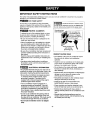 3
3
-
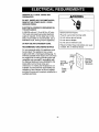 4
4
-
 5
5
-
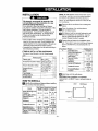 6
6
-
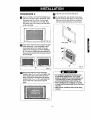 7
7
-
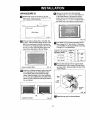 8
8
-
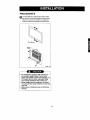 9
9
-
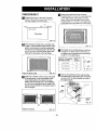 10
10
-
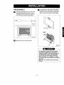 11
11
-
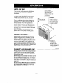 12
12
-
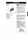 13
13
-
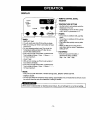 14
14
-
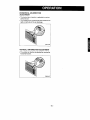 15
15
-
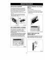 16
16
-
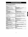 17
17
-
 18
18
-
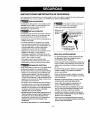 19
19
-
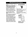 20
20
-
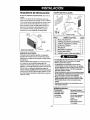 21
21
-
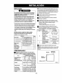 22
22
-
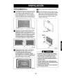 23
23
-
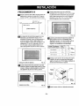 24
24
-
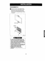 25
25
-
 26
26
-
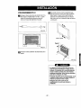 27
27
-
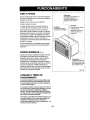 28
28
-
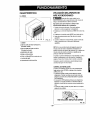 29
29
-
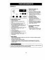 30
30
-
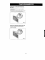 31
31
-
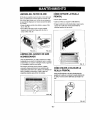 32
32
-
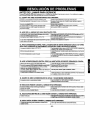 33
33
-
 34
34
-
 35
35
-
 36
36


Kenmore 580.73093 El manual del propietario
- Tipo
- El manual del propietario
En otros idiomas
- English: Kenmore 580.73093 Owner's manual
Documentos relacionados
-
Kenmore 580.75119500 El manual del propietario
-
Kenmore 580.74123300 El manual del propietario
-
-
-
-
-
-