ATEN VE170 Guía de inicio rápido
- Categoría
- Extensores AV
- Tipo
- Guía de inicio rápido
Este manual también es adecuado para

User Guide
A/V Over Cat 5 Extender
© Copyright 2012 ATEN® International Co., Ltd.
ATEN and the ATEN logo are trademarks of ATEN International Co., Ltd. All rights reserved. All other
trademarks are the property of their respective owners.
This product is RoHS compliant.
Part No. PAPE-1285-181G Printing Date: 04/2012
VE170 A/V Over Cat 5 Extender User Instructions
Prolongateur VE170 A/V Cat 5 - manuel d’utilisation
VE170 Audio-Video-Verlängerung Over Cat 5 Bedienungsanleitung
VE170 Alargador A/V sobre Cat. 5 instrucciones para el usuario
Requirements
Source Device
The following equipment must be installed on the source device or computer that acts as a
source of VGA/Audio content:
•HDB-15connector
•Audioport(optional)
Transmitter
•ATENVE170TA/VOverCat5Transmitteror
•ATENVS1204T/VS1208T4/8-portA/VOverCat5Splitter
Receiver
•ATENVE170RA/VOverCat5Receiveror
•ATENVE170RQA/VOverCat5ReceiverwithDeskew
Display Device
•AVGA,SVGA,XGA,SXGA,WUXGAormultisyncdisplaydeviceorreceiverwithanHDB-
15 connector
•Speakers(optional)
Cables
•UseaVGA/Audiocableconnectthesourcedevicetothetransmitter(VE170T/VS1204T/
VS1208T)
•UseCat5ecabletoconnectthetransmitter(VE170T/VS1204T/VS1208T)totheVE170R
/VE170RQreceiver
•UseaVGA/AudiocableconnecttheVE170R/VE170RQtothedisplaydevice
Maximum Cable Distance
Source device Transmitter(VE170T/VS1204T/VS1208T):10m
Transmitter Local Display: 20m
Transmitter Receiver(VE170R/VE170RQ):300m
Receiver Remote Display: 20 m
Conguration minimale
Périphérique source
Le composant suivant doit être installé sur le périphérique source ou sur l’ordinateur agissant
en tant que source du contenu VGA/audio :
•ConnecteurHDB-15
•Portdesortieaudio(facultatif)
Transmetteur
•TransmetteurATENVE170TA/VCat5ou
•RépartiteurATENA/VCat54/8portsVS1204T/VS1208T
Récepteur
•RécepteurATENVE170RA/VCat5ou
•RécepteurATENVE170RA/VCat5avecDeskew
Périphérique d’afchage
•Unpériphériqued’afchageVGA,SVGA,XGA,SXGA,WUXGAoumultisyncouun
récepteur équipé d’un connecteur HDB-15
•Deshaut-parleurs(facultatifs)
Câbles
•UtilisezuncâbleVGA/audiopourconnecterlepériphériquesourceautransmetteur(VE170T
/VS1204T/VS1208T)
•Utilisezuncâbledecatégorie5epourconnecterletransmetteur(VE170T/VS1204T/
VS1208T)aurécepteurVE170R/VE170RQ
•UtilisezuncâbleVGA/audiopourconnecterleVE170R/VE170RQaupériphérique
d’afchage
Longueur de câble maximale
Périphérique source Transmetteur(VE170T/VS1204T/VS1208T):10m
Transmetteur Écran local : 20 m
Transmetteur Récepteur(VE170R/VE170RQ):300m
Récepteur Écran distant : 20 m
Voraussetzungen
Signalquelle
Auf den Signalquellen oder Computern, die das VGA-/Audiosignal senden, muss mindestens
Folgendes installiert sein:
•HDB-15-Anschluss
•Audioausgangsbuchse(optional)
Sender
•ATENVE170TAudio-Video-SenderOverCat5oder
•ATENVS1204T/VS1208TAudio-Video-SplitterOverCat5mit4/8Ports
Empfänger
•ATENVE170RAudio-Video-EmpfängerOverCat5oder
•ATENVE170RQAudio-Video-EmpfängerOverCat5mitSignalkompensation
Anzeigegerät
•EinVGA,SVGA-,XGA-,SXGA-,WUXGA-oderMultisync-Anzeigegerätbzw.
–Empfangsgerät mit HDB-15-Buchse
•Lautsprecher(optional)
Kabel
•VerbindenSiedieSignalquellemitdemSender(VE170T/VS1204T/VS1208T).Verwenden
SiedazueinVGA-/Audio-Kabel.
•VerbindenSiedenSender(VE170T/VS1204T/VS1208T)übereinKat.5e-Kabelmitdem
VE170R-/VE170RQ-Empfänger.
•VerbindenSiedenVE170R/VE170RQmitdemAnzeigegerät.VerwendenSiedazuein
VGA-/Audio-Kabel.
Maximale Kabellänge
Signalquelle Sender(VE170T/VS1204T/VS1208T):10m
Sender LokalesAnzeigegerät:20m
Sender Empfänger(VE170R/VE170RQ):300m
Sender EntferntesAnzeigegerät:20m
Requisitos
Dispositivo fuente
En los dispositivos fuente de señal de audio/VGA u ordenadores que se conectan al equipo
debe estar instalado lo siguiente:
•ConectorHDB-15
•Puertodesalidadeaudio(opcional)
Transmisor
•TransmisorA/VsobreCat.5ATENVE170To
•RepartidordeseñalA/VsobreCat.5de4/8puertosATENVS1204T/VS1208T
Receptor
•ReceptorA/VsobreCat.5ATENVE170Ro
•ReceptorA/VsobreCat.5ATENVE170RQconcompensacióndeseñal
Dispositivo de visualización
•UndispositivodevisualizaciónVGA,SVGA,XGA,SXGA,WUXGAomultisyncoun
receptor con un conector HDB-15
•Altavoces(opcional)
Cables
•Conecteeldispositivofuentealtransmisor(VE170T/VS1204T/VS1208T).Paraello,
emplee un cable VGA/audio.
•UtiliceuncabledeCat.5eparaconectareltransmisor(VE170T/VS1204T/VS1208T)al
receptorVE170R/VE170RQ.
•ConecteelVE170R/VE170RQaldispositivodevisualización.Paraello,empleeuncable
VGA/audio.
Longitudes de cables máximas
Dispositivo fuente de señal Transmisor(VE170T/VS1204T/VS1208T):10m
Transmisor Pantalla local: 20 m
Transmisor Receptor(VE170R/VE170RQ):300m
Receptor Pantalla distante: 20 m
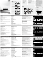
Hardware Review
A
A. VE170T Front View
1. Video Input Port
2. Video Output Port
B. VE170R Front View
1. Video Output Port
2. Audio Output Port
C. VE170RQ Front View
1. Video Output Port
2. Audio Output Port
3.RGBTuner
D. VE170R / VE170RQ Rear View
1. Grounding Terminal
2. Video Gain Tuner
3.VideoCompensationTuner
4. Line In Port
5. Power Jack
6.PowerLED(top)
E. VE170T Rear View
1. Grounding Terminal
2. Audio Input Port
3.AudioOutputPort
4. Line Out Port
5. Power Jack
6.PowerLED(top)
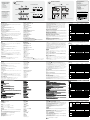
Hardware Installation
B
• Beforebeginningtheinstallationprocedure,ensurethatallequipmenttobeconnectedis
powered off.
• Topreventdamagetoyourinstallation,makesurethatalldevicesareproperlygrounded.
Description de l’appareil
A
A. VE170T – Vue avant
1. Port d’entrée vidéo
2. Port de sortie vidéo
B. VE170R – Vue avant
1. Port de sortie vidéo
2. Port de sortie audio
C. VE170RQ – Vue avant
1. Port de sortie vidéo
2. Port de sortie audio
3.RéglageRGB
D. VE170R / VE170RQ – Vue arrière
1. Prise de terre
2. Réglage de gain vidéo
3.Réglagedecompensationvidéo
4. Port d’entrée de ligne
5. Prise d’alimentation
6.Voyantd’alimentation(sommet)
E. VE170T – Vue arrière
1. Prise de terre
2. Port d’entrée audio
3.Portdesortieaudio
4. Sortie de ligne
5. Prise d’alimentation
6.Voyantd’alimentation(sommet)
Installation du matériel
B
• Avantdedémarrerlaprocédured’installation,assurez-vousquetouslespériphériquesà
connecter sont éteints.
• And’éviterd’endommagervotreinstallation,vériezquetouslespériphériquessont
correctementreliésàlaterre.
Hardwareübersicht
A
A. Vorderseitige Ansicht des VE170T
1.Graksignaleingang
2.Graksignalausgang
B. Vorderseitige Ansicht des VE170R
1. Graksignalausgang
2. Audiosignalausgang
C. Vorderseitige Ansicht des VE170RQ
1.Graksignalausgang
2. Audiosignalausgang
3.RGB-Tuner
D. Rückseitige Ansicht des VE170R / VE170RQ
1. Erdungsanschluss
2. Bildsignalpegelregler
3.Bildsignalkompensationsregler
4. Line-In-Buchse
5. Stromeingangsbuchse
6.LED-Betriebsanzeige(oben)
E. Rückseitige Ansicht des VE170T
1. Erdungsanschluss
2. Audiosignaleingang
3.Audiosignalausgang
4. Line-Out
5. Stromeingangsbuchse
6.LED-Betriebsanzeige(oben)
Hardware installieren
B
• SchaltenSievorderInstallationalleanzuschließendenGeräteaus.
• UmeineBeschädigungIhrerGerätezuvermeiden,müssenalleGeräteordnungsgemäß
geerdet sein.
Presentación del hardware
A
A. VE170T – Vista frontal
1.Puertodeentradadeseñalgráca
2.Puertodesalidadeseñalgráca
B. VE170R – Vista frontal
1. Puertodesalidadeseñalgráca
2. Puerto de salida de audio
C. VE170RQ – Vista frontal
1.Puertodesalidadeseñalgráca
2. Puerto de salida de audio
3.SintonizadorRVA
D. VE170R / VE170RQ – Vista posterior
1. Toma de tierra
2.Ajustedegananciadeseñalgráca
3.Ajustedecompensacióndeseñalgráca
4. Entrada de línea Line-In
5.Entradadealimentación
6.Indicadordealimentación(arriba)
E. VE170T – Vista posterior
1. Terminal de tierra
2. Puerto de entrada de audio
3.Puertodesalidadeaudio
4.Salidadelínea(Line-Out)
5.Entradadealimentación
6.Indicadordealimentación(arriba)
Instalar el hardware
B
• Antesdeiniciarelprocesodeinstalación,asegúresedequetodoslosequiposquevayaa
conectar estén apagados.
• Paraevitardañosenlosdispositivos,veriquequetodosellosesténconectadosatierra
correctamente.
1. Connect one end of a VGA/Audio cable to the video and audio ports on the A/V source
device(e.g.computerorDVDplayer).
2. Connect the other end of the VGA/Audio cable to the Video In and Audio In ports located on
thetransmitter(VE170T/VS1204T/VS1208T).
3.ConnectthelocaldisplayandspeakerstotheVideoOutandAudioOutportsontheunit
4. Use Cat 5e cable to connect the RJ-45 Line Out Ports on the VE170T / VS1204T /
VS1208TtotheLineInPortontheVE170R/VE170RQ.
5. Plug the remote display’s video and audio cables into the Video Out and Audio Out ports on
theVE170R/VE170RQ.
6. Using the power adapter supplied with this package, connect the unit to an AC power outlet.
7. Turn on the source and display devices.
Picture Adjustment
The quality of the video signal can decrease with distance. Use the Video Gain Control
and Video compensation knobs to increase/ decrease the video signal gain and adjust the
compensation.
Deskew (VE170RQ only)
TheVE170RQfeaturesATEN’spatentedDeskewtechnology.Tone-tunethevideosignal,
use the RGB Tuner knobs to increase/decrease the delay time of the red, green, or blue color
signals.
Din Rail and Wall Mounting
To mount the VE170 on a din rail do the following:
•Usingthescrewsprovidedwiththispackage,screwthemountingbracketintothebottomof
theunit,thenscrewtheprovidedclippersintothebracketandnallycliptheVE170tothe
Din Rail.
To mount the VE170 on a wall do the following:
•Usingthescrewsprovidedwiththispackage,screwthemountingbracketintothebottomof
the unit, and then screw the bracket into the wall.
Note:TheVE170RackMountKitsupportstheVESAFDMImountstandard.
1.Reliezl’unedesextrémitésd’uncâbleaudio/VGAauxportsaudioetvidéodupériphérique
sourceA/V(ordinateuroulecteurDVD,parexemple).
2.Reliezl’autreextrémitéducâbleVGA/audioauxportsd’entréevidéoetaudiosituéssurle
transmetteur(VE170T/VS1204T/VS1208T).
3.Branchezl’écranetleshaut-parleurslocauxsurlesportsdesortievidéoetaudiode
l’appareil
4.Utilisezlecâbledecatégorie5epourconnecterlesportsdesortiedeligneRJ-45du
VE170T/VS1204T/VS1208Tauportd’entréedeligneduVE170R/VE170RQ.
5.Branchezlescâblesaudioetvidéodel’écrandistantauxportsdesortieaudioetvidéodu
VE170R/VE170RQ.
6.Branchezl’appareilsuruneprisedecourantàl’aidedel’adaptateursecteurfourni.
7.Allumezlespériphériquesd’afchageetsource.
Réglage de l’image
La qualité du signal vidéo peut diminuer avec la distance. À l’aide des boutons rotatifs de
contrôledegainvidéoetdecompensationvidéo,augmentez/diminuezlegaindusignalet
réglezlacompensation.
Deskew (VE170RQ uniquement)
LeVE170RQutiliselatechnologiebrevetéeDeskewd’ATEN.Pour leréglagen dusignal
vidéo,utilisez lesboutonsrotatifs de réglageRGBpour augmenter/diminuerleretarddes
signaux rouge, vert ou bleu.
Montage au mur ou sur rail
PourmonterleVE170surrail,procédezcommesuit:
•Vissezlesupportdemontagesurlapartieinférieuredel’unité(àl’aidedesvisfournies).
Vissezensuitelesattachesfourniessurlesupport,puisxezleVE170aurail.
PourmonterleVE170aumur,procédezcommesuit:
•Vissezlesupportdemontagesurlapartieinférieuredel’appareil(àl’aidedesvisfournies),
puisxezlesupportaumur.
Remarque: lekitpourmonterleVE170surbâtiprendenchargelestandardFDMIVESA.
1.VerbindenSiedaseineEndedesVGA/AudiokabelsmitdenGrak-undAudioausgängen
derAV-Signalquelle(z.B.ComputeroderDVD-Player).
2.VerbindenSiedasandereEndedesVGA-/AudiokabelsmitdenGrak-und
AudiosignaleingängenaufderSenders(VE170T/VS1204T/VS1208T).
3.VerbindenSiedenlokalenBildschirmunddielokalenLautsprechermitdenGrak-und
Audiosignalausgängen des Gerätes.
4.VerbindenSiedieRJ45-Line-Out-AusgängeamVE170T/VS1204T/VS1208Tüberein
Kat.5e-KabelmitdemLine-In-EingangamVE170R/VE170RQ.
5.VerbindenSiedasGrak-unddasAudiokabeldesBildschirmsderGegenstellemitden
Grak-undAudiosignalausgängenamVE170R/VE170RQ.
6.VerbindenSiedasmitgelieferteNetzteilmitdemGerätundeinerSteckdose.
7.SchaltenSiedieSignalquelleunddasAnzeigegerätein.
Bildeinstellung
DieQualitätdesGrafiksignalskannüberdieEntfernungabnehmen.Verwenden Sieden
Bildsignalpegelregler und den Bildkompensationsregler, um den Gewinn des Bildsignals
anzuhebenbzw.abzusenkenunddieKompensationeinzustellen.
Signalkompensation (Nur beim VE170RQ)
DerVE170RQbeinhaltetdiepatentierteSignalkompensationstechnologievonATEN.Umdas
Bildsignalabzustimmen,drehenSiedie RGB-Regler,und erhöhenbzw.verringernSie die
LaufzeitderFarbsignaleRot,GrünundBlau.
Hutschienen- und Wandmontage
UmdenVE170aufeineHutschienezusetzen,gehenSiefolgendermaßenvor:
•VerwendenSiediemitgeliefertenSchrauben,umdenMontagerahmenaufdieUnterseite
desGeräteszuschrauben.AnschließendbringenSiediemitgeliefertenKlammernanund
setzendenVE170aufdieHutschiene.
UmdenVE170anderWandzumontieren,gehenSiefolgendermaßenvor:
•VerwendenSiediemitgeliefertenSchrauben,umdenMontagerahmenaufdieUnterseite
desGeräteszuschrauben.AnschließendbringenSiedenRahmenanderWandan.
Hinweis:DasKitzurRackmontagedesVE170unterstütztdenVESA-FDMI-Standard.
1.Conecteunextremodelcabledeaudio/VGAalospuertosdeaudioygrácodeldispositivo
fuenteA/V(p.ej.ordenadororeproductordeDVD).
2.Conecteelotroextremodelcabledeaudio/VGAalospuertosdeentradadeaudioygráca
ubicadoseneltransmisor(VE170T/VS1204T/VS1208T).
3.Conectelapantallaylosaltavoceslocalesalospuertosdesalidagrácaydeaudiodela
unidad.
4.UtiliceuncabledeCat.5eparaconectarlospuertosdesalidadelíneaRJ-45(Line-Out)
delVE170T/VS1204T/VS1208Talpuertodeentradadelínea(Line-In)delVE170R/
VE170RQ..
5.Conecteloscablesdeaudioygrácodelapantalladistantealospuertosdesalidade
audioyseñalgrácadelVE170R/VE170RQ.
6.Conectelaunidadaunatomaeléctricamedianteeladaptadordealimentaciónincluido.
7.Enciendalosdispositivosdevisualizaciónyfuente.
Ajuste de la imagen
Lacalidaddelaseñalgrácapuededeteriorarseconladistancia.Utilicelosajustespara
lagananciadelaseñalgráficayparalacompensacióndeseñal paraampliar/atenuarla
gananciadeseñalyparaajustarlacompensación.
Compensación de señal (sólo para el VE170RQ)
ElVE170RQincorporalatecnologíadecompensacióndeseñaldeATEN.Paraajustar
laseñalgráca,girelosdialesde ajusteRVAparaincrementaroreducirelretardo delas
señalesparaloscoloresrojo,verdeyazul.
Montaje sobre raíl o en la pared
ParamontarelVE170sobreunraíl,procedacomoseindicaacontinuación:
•Atornilleelmarcodemontajeenlaparteinferiordelaunidad(conlostornillosincluidos),
luegoatornillelasjacionesincluidasenelmarcoyjeelVE170alraíl.
ParamontarelVE170enlapared,procedacomoseindicaacontinuación:
•Atornilleelmarcodemontajeenlaparteinferiordelaunidad(conlostornillosincluidos)y
luegojeelmarcoalapared.
Nota: ElkitparamontarelVE170enrackadmiteelestándarFDMIVESA.
VE170T / VE170R / VE170RQ
Specications
Function VE170T VE170R VE170RQ
Connectors
Video In 1xHDB-15Male
(Blue) N/A
Video Out 1xHDB-15Female(Blue)
Audio In 1 x Audio Jack
Female(Green) N/A
Audio Out 1xAudioJackFemale(Green)
Unit to Unit 1 x RJ-45 Female
Power 1 x DC Jack
LEDs Power N/A 1(Green)
Switch
ManualGain
Control N/A 2xKnob
RGB Tuner N/A N/A 3xKnob
Video
1920x1200@60Hz(30m)
1600x1200@60Hz(150m)
1024x768@60Hz(300m)
1920x1200 @
60Hz(150m)
1280x1024 @
60Hz(300m)
Cable Distance 300m
Power Consumption DC5.3V,0.9W DC5.3V,1.11W DC5.3V,1.43W
Environment
Operating
Temp. 0–50°C
Storage Temp. -20–60°C
Humidity 0–80% RH, Non-condensing
Physical
Properties
Housing Metal
Weight 0.25 kg
Dimensions
(LxWxH) 11.95 x 8.56 x 2.26 cm
Caractéristiques techniques
Fonction VE170T VE170R VE170RQ
Connecteurs
Entrée vidéo
1 connecteur
HDB-15mâle
(bleu)
N/D
Sortie vidéo 1connecteurHDB-15femelle(bleu)
Entrée audio
1 connecteur
audio femelle
(vert)
N/D
Sortie audio 1connecteuraudiofemelle(vert)
Portd’unitéà
unité 1 connecteur RJ-45 femelle
Alimentation 1 prise d’alimentation CC
Voyants Alimentation N/D 1voyant(vert)
Commutateur
Contrôle du
gain manuel N/D 2 bouton
Réglage RGB N/D N/D 3bouton
Vidéo
1920x1200à60Hz(30m);
1600x1200à60Hz(150m);
1024x768à60Hz(300m)
1920x1200à
60Hz(150m);
1280x1024à
60Hz(300m)
Longueurdecâble 300m
Consommation électrique 5,3Vc.c.,0,9W 5,3Vc.c.,1,11W 5,3Vc.c.,1,43W
Environne-
ment
Température de
fonctionnement 0à50°C
Température
de stockage -20à60°C
Humidité Humiditérelativede0à80%,sanscondensation
Propriétés
physiques
Boîtier Métallique
Poids 0,25 kg
Dimensions
(LxlxH) 11,95 x 8,56 x 2,26 cm
Technische Daten
Funktion VE170T VE170R VE170RQ
Anschlüsse
Grakeingänge 1 x HDB-15
Männlein(blau) --
Grakausgänge 1xHDB-15Weiblein(blau)
Audio-Eingänge
1 x Audio-
Buchse,Weiblein
(grün)
--
Audio-Ausgang 1xAudio-Buchse,Weiblein(grün)
Gerät an Gerät 1xRJ-45Weiblein
Stromversorgung 1 x Stromeingangsbuchse
LED-Anzeigen Stromversorgung -- 1(grün)
Schalter
Manuelle
Pegeleinstellung -- 2 x Drehregler
RGB-Tuner -- -- 3xDrehregler
Grak
1920x1200bei60Hz(30m);
1600x1200bei60Hz(150m);
1024x768bei60Hz(300m)
1920 x 1200 bei
60Hz(150m);
1280 x 1024 bei
60Hz(300m)
Kabellänge 300m
Stromverbrauch 5,3V=,0,9W 5,3V=,1,11W 5,3V=,1,43W
Umgebung
Betriebstemperatur 0-50 °C
Lagertemperatur -20-60 °C
Feuchtigkeit 0 -80% rel. Luftfeuchte, nicht kondensierend
Physische
Eigenschaften
Gehäuse Metall
Gewicht 0,25 kg
Abmessungen
(LxBxH) 11,95 x 8,56 x 2,26 cm
Especicaciones
Función VE170T VE170R VE170RQ
Conectores
Entrada de señal
gráca
1 conector HDB-15
macho(azul) --
Salida de señal
gráca 1conectorHDB-15hembra(azul)
Entra da de audio 1 conector audio
hembra(verde) --
Salida de audio 1conectoraudiohembra(verde)
Puerto de unidad
a unidad 1 conector RJ-45 hembra
Alimentación 1 toma de c.c.
Indicadores
LED Alimentación -- 1(verde)
Conmutador
Control de
ganancia manual -- 2 botones
SintonizadorRVA -- -- 3botones
Señalgráca
1920x1200a60Hz(30m);
1600x1200a60Hz(150m);
1024x768a60Hz(300m)
1920 x 1200 a 60
Hz(150m);
1280x1024a60Hz
(300m)
Longitud de cable 300m
Consumo 5,3Vdec.c.,0,9W 5,3Vdec.c.,1,11
W
5,3Vdec.c.,1,43
W
Entorno
Temperatura de
funcionamiento 0 a 50 °C
Temperatura de
almacenamiento -20 a 60 °C
Humedad 0 a 80% de HR, sin condensar
Propiedades
físicas
Carcasa Metálica
Peso 0,25 kg
Dimensiones
(LxAnxAl) 11,95 x 8,56 x 2,26 cm
Hardware Installation
The following contains information that relates to China:
FCC Information
This equipment has been tested and found to comply with
the limits for a Class B digital device, pursuant to Part 15
of the FCC Rules. These limits are designed to provide
reasonable protection against harmful interference in a
residential installation. This equipment generates, uses
and can radiate radio frequency energy, and if not installed
and used in accordance with the instruction manual, may
cause interference to radio communications. However,
there is no guarantee that interference will not occur in a
particular installation. If this equipment does cause harmful
interference to radio or television reception, which can be
determined by turning the equipment off and on, the user
is encouraged to try to correct the interference by one or
more of the following measures:
•Reorientorrelocatethereceivingantenna;
•Increasetheseparationbetweentheequipmentand
receiver;
•Connecttheequipmentintoanoutletonacircuitdifferent
fromthatwhichthereceiverisconnected;
•Consultthedealer/anexperiencedradio/television
technician for help.
A. VE170T Front View
B. VE170R Front View
C. VE170RQ Front View
D. VE170R/VE170RQ Rear View
E. VE170T Rear View
Online Registration
International:
http://support.aten.com
North America:
http://www.aten-usa.com/product_registration
Technical Phone Support
International:
886-2-86926959
North America:
1-888-999-ATEN Ext: 4988
United Kingdom:
44-8-4481-58923
Package Contents
1 VE170T or VE170R or
VE170RQA/VOverCat5
Extender
1 Power Adapter
1MountingKit(1pc)
1 User Instructions
Package Contents
1VE170T+VE170Ror1VE170T+VE170RQ
A/V Over Cat 5 Extender
1VGA/AudioCable(1.8m)
2 Power Adapters
1MountingKit(2pcs)
1 User Instructions
www.aten.com
www.aten.com
www.aten.com
www.aten.com
Hardware Review
A
1 2 3 4 5 6
GAI N CO MP LINE IN
1 2 3 4 5 6
B
Cat 5e Cable (300m)
Transmitter Receiver
VE170T VE170RQ
VI DEO OUT
VIDEO NI VIDE O OU T
R
B G
LINE
OUT
OUTIN
AUD IO
GAIN C OM P LINE IN
6
3
3
4
5
6
1
2
2
3
3
4
5
66
1 2 3 4 5 6
LINE
OUT
OU TIN
AU DI O
1 2 3 4 5 6
1 2
VI DEO OUT
VIDEO NI
1 2
1 2
VIDE O OUT
1 2
VIDE O OUT
R
B G
1 2 3
1 2 3
La página se está cargando...
Transcripción de documentos
A Hardware Review A. VE170T Front View 11 2 2 VIDEO I N B. VE170R Front View 1 VE170T or VE170R or VE170RQ A/V Over Cat 5 Extender 1 Power Adapter 1 Mounting Kit (1 pc) 1 User Instructions 1 VE170T + VE170R or 1 VE170T + VE170RQ A/V Over Cat 5 Extender 1 VGA/Audio Cable (1.8m) 2 Power Adapters 1 Mounting Kit (2 pcs) 1 User Instructions B C. VE170RQ Front View 1 2 G Hardware Installation 44 3 B VE170T VE170RQ Cat 5e Cable (300m) International: http://support.aten.com North America: http://www.aten-usa.com/product_registration 2 D. VE170R/VE170RQ Rear View LINE OUT AUDIO IN 2 2 33 4 4 5 5 GAIN COMP Technical Phone Support LINE IN 6 6 6 6 LINE IN GAIN COMP B VIDEO I N E. VE170T Rear View © Copyright 2012 ATEN® International Co., Ltd. ATEN and the ATEN logo are trademarks of ATEN International Co., Ltd. All rights reserved. All other trademarks are the property of their respective owners. 1 1 2 2 33 Part No. PAPE-1285-181G 4 4 IN Printing Date: 04/2012 5 5 G R The following contains information that relates to China: VIDEO OUT VIDEO OUT 2 6 6 5 5 3 3 1 LINE OUT AUDIO This product is RoHS compliant. International: 886-2-86926959 North America: 1-888-999-ATEN Ext: 4988 United Kingdom: 44-8-4481-58923 OUT 6 6 User Guide Online Registration 3 3 R VIDEO OUT 1 1 This equipment has been tested and found to comply with the limits for a Class B digital device, pursuant to Part 15 of the FCC Rules. These limits are designed to provide reasonable protection against harmful interference in a residential installation. This equipment generates, uses and can radiate radio frequency energy, and if not installed and used in accordance with the instruction manual, may cause interference to radio communications. However, there is no guarantee that interference will not occur in a particular installation. If this equipment does cause harmful interference to radio or television reception, which can be determined by turning the equipment off and on, the user is encouraged to try to correct the interference by one or more of the following measures: • Reorient or relocate the receiving antenna; • Increase the separation between the equipment and receiver; • Connect the equipment into an outlet on a circuit different from that which the receiver is connected; • Consult the dealer/an experienced radio/television technician for help. 22 VIDEO OUT VE170T / VE170R / VE170RQ Package Contents VIDEO OUT 11 A/V Over Cat 5 Extender FCC Information Package Contents OUT Transmitter Receiver VE170 A/V Over Cat 5 Extender User Instructions www.aten.com Requirements Hardware Review Source Device A. VE170T Front View The following equipment must be installed on the source device or computer that acts as a source of VGA/Audio content: • HDB-15 connector • Audio port (optional) 1. Video Input Port 2. Video Output Port Transmitter 1. Video Output Port 2. Audio Output Port • ATEN VE170T A/V Over Cat 5 Transmitter or • ATEN VS1204T / VS1208T 4/8-port A/V Over Cat 5 Splitter Receiver • ATEN VE170R A/V Over Cat 5 Receiver or • ATEN VE170RQ A/V Over Cat 5 Receiver with Deskew Display Device • A VGA, SVGA, XGA, SXGA, WUXGA or multisync display device or receiver with an HDB15 connector • Speakers (optional) Cables • Use a VGA/Audio cable connect the source device to the transmitter (VE170T / VS1204T / VS1208T) • Use Cat 5e cable to connect the transmitter (VE170T / VS1204T / VS1208T) to the VE170R / VE170RQ receiver • Use a VGA/Audio cable connect the VE170R / VE170RQ to the display device Maximum Cable Distance Source device Transmitter (VE170T / VS1204T / VS1208T): 10 m Transmitter Local Display: 20m Transmitter Receiver (VE170R / VE170RQ): 300 m Receiver Remote Display: 20 m 1. Connect one end of a VGA/Audio cable to the video and audio ports on the A/V source device (e.g. computer or DVD player). 2. Connect the other end of the VGA/Audio cable to the Video In and Audio In ports located on the transmitter (VE170T / VS1204T / VS1208T). 3. Connect the local display and speakers to the Video Out and Audio Out ports on the unit 4. Use Cat 5e cable to connect the RJ-45 Line Out Ports on the VE170T / VS1204T / VS1208T to the Line In Port on the VE170R / VE170RQ. 5. Plug the remote display’s video and audio cables into the Video Out and Audio Out ports on the VE170R / VE170RQ. 6. Using the power adapter supplied with this package, connect the unit to an AC power outlet. 7. Turn on the source and display devices. A B. VE170R Front View C. VE170RQ Front View 1. Video Output Port 2. Audio Output Port 3. RGB Tuner Picture Adjustment The quality of the video signal can decrease with distance. Use the Video Gain Control and Video compensation knobs to increase/ decrease the video signal gain and adjust the compensation. D. VE170R / VE170RQ Rear View 1. Grounding Terminal 2. Video Gain Tuner 3. Video Compensation Tuner 4. Line In Port 5. Power Jack 6. Power LED (top) Deskew (VE170RQ only) The VE170RQ features ATEN’s patented Deskew technology. To fine-tune the video signal, use the RGB Tuner knobs to increase/decrease the delay time of the red, green, or blue color signals. 1. Grounding Terminal 2. Audio Input Port 3. Audio Output Port 4. Line Out Port 5. Power Jack 6. Power LED (top) Hardware Installation B • Before beginning the installation procedure, ensure that all equipment to be connected is powered off. • To prevent damage to your installation, make sure that all devices are properly grounded. Function Video In Video Out Connectors Audio In LEDs Audio Out Unit to Unit Power Power Manual Gain Control RGB Tuner Switch VE170T VE170R VE170RQ 1 x HDB-15 Male N/A (Blue) 1 x HDB-15 Female (Blue) 1 x Audio Jack N/A Female (Green) 1 x Audio Jack Female (Green) 1 x RJ-45 Female 1 x DC Jack N/A 1 (Green) N/A 2 x Knob N/A N/A 3 x Knob 1920x1200 @ 60Hz (150 m) 1280x1024 @ 60Hz (300 m) 1920x1200 @ 60Hz (30 m) 1600x1200 @ 60Hz (150 m) 1024x768@ 60Hz (300 m) Video To mount the VE170 on a din rail do the following: • Using the screws provided with this package, screw the mounting bracket into the bottom of the unit, then screw the provided clippers into the bracket and finally clip the VE170 to the Din Rail. Cable Distance Power Consumption Operating Temp. Environment Storage Temp. Humidity To mount the VE170 on a wall do the following: • Using the screws provided with this package, screw the mounting bracket into the bottom of the unit, and then screw the bracket into the wall. Physical Properties Din Rail and Wall Mounting E. VE170T Rear View Specifications 300 m DC5.3V, 1.11W DC5.3V, 0.9 W -20–60°C 0–80% RH, Non-condensing Housing Metal Weight Dimensions (L x W x H) Note: The VE170 Rack Mount Kit supports the VESA FDMI mount standard. DC5.3V, 1.43W 0–50°C 0.25 kg 11.95 x 8.56 x 2.26 cm Prolongateur VE170 A/V Cat 5 - manuel d’utilisation www.aten.com Configuration minimale Description de l’appareil Périphérique source A. VE170T – Vue avant Le composant suivant doit être installé sur le périphérique source ou sur l’ordinateur agissant en tant que source du contenu VGA/audio : • Connecteur HDB-15 • Port de sortie audio (facultatif) 1. Port d’entrée vidéo 2. Port de sortie vidéo B. VE170R – Vue avant Transmetteur 1. Port de sortie vidéo 2. Port de sortie audio • Transmetteur ATEN VE170T A/V Cat 5 ou • Répartiteur ATEN A/V Cat 5 4/8 ports VS1204T / VS1208T C. VE170RQ – Vue avant Récepteur • Récepteur ATEN VE170R A/V Cat 5 ou • Récepteur ATEN VE170R A/V Cat 5 avec Deskew Périphérique d’affichage • Un périphérique d’affichage VGA, SVGA, XGA, SXGA, WUXGA ou multisync ou un récepteur équipé d’un connecteur HDB-15 • Des haut-parleurs (facultatifs) Câbles • Utilisez un câble VGA/audio pour connecter le périphérique source au transmetteur (VE170T / VS1204T / VS1208T) • Utilisez un câble de catégorie 5e pour connecter le transmetteur (VE170T / VS1204T / VS1208T) au récepteur VE170R / VE170RQ • Utilisez un câble VGA/audio pour connecter le VE170R / VE170RQ au périphérique d’affichage Longueur de câble maximale Périphérique source Transmetteur (VE170T / VS1204T / VS1208T) : 10 m Transmetteur Écran local : 20 m Transmetteur Récepteur (VE170R / VE170RQ) : 300 m Récepteur Écran distant : 20 m 1. Reliez l’une des extrémités d’un câble audio/VGA aux ports audio et vidéo du périphérique source A/V (ordinateur ou lecteur DVD, par exemple). 2. Reliez l’autre extrémité du câble VGA/audio aux ports d’entrée vidéo et audio situés sur le transmetteur (VE170T / VS1204T / VS1208T). 3. Branchez l’écran et les haut-parleurs locaux sur les ports de sortie vidéo et audio de l’appareil 4. Utilisez le câble de catégorie 5e pour connecter les ports de sortie de ligne RJ-45 du VE170T / VS1204T / VS1208T au port d’entrée de ligne du VE170R / VE170RQ. 5. Branchez les câbles audio et vidéo de l’écran distant aux ports de sortie audio et vidéo du VE170R / VE170RQ. 6. Branchez l’appareil sur une prise de courant à l’aide de l’adaptateur secteur fourni. 7. Allumez les périphériques d’affichage et source. A 1. Port de sortie vidéo 2. Port de sortie audio 3. Réglage RGB Réglage de l’image La qualité du signal vidéo peut diminuer avec la distance. À l’aide des boutons rotatifs de contrôle de gain vidéo et de compensation vidéo, augmentez/diminuez le gain du signal et réglez la compensation. D. VE170R / VE170RQ – Vue arrière 1. Prise de terre 2. Réglage de gain vidéo 3. Réglage de compensation vidéo 4. Port d’entrée de ligne 5. Prise d’alimentation 6. Voyant d’alimentation (sommet) Deskew (VE170RQ uniquement) Le VE170RQ utilise la technologie brevetée Deskew d’ATEN. Pour le réglage fin du signal vidéo, utilisez les boutons rotatifs de réglage RGB pour augmenter/diminuer le retard des signaux rouge, vert ou bleu. E. VE170T – Vue arrière Montage au mur ou sur rail 1. Prise de terre 2. Port d’entrée audio 3. Port de sortie audio 4. Sortie de ligne 5. Prise d’alimentation 6. Voyant d’alimentation (sommet) Pour monter le VE170 sur rail, procédez comme suit : • Vissez le support de montage sur la partie inférieure de l’unité (à l’aide des vis fournies). Vissez ensuite les attaches fournies sur le support, puis fixez le VE170 au rail. Installation du matériel Pour monter le VE170 au mur, procédez comme suit : • Vissez le support de montage sur la partie inférieure de l’appareil (à l’aide des vis fournies), puis fixez le support au mur. B • Avant de démarrer la procédure d’installation, assurez-vous que tous les périphériques à connecter sont éteints. • Afin d’éviter d’endommager votre installation, vérifiez que tous les périphériques sont correctement reliés à la terre. Remarque: le kit pour monter le VE170 sur bâti prend en charge le standard FDMI VESA. Caractéristiques techniques Fonction VE170T VE170R VE170RQ 1 connecteur HDB-15 mâle N/D (bleu) 1 connecteur HDB-15 femelle (bleu) 1 connecteur audio femelle N/D (vert) 1 connecteur audio femelle (vert) Entrée vidéo Sortie vidéo Entrée audio Connecteurs Sortie audio Port d’unité à unité Alimentation Voyants Alimentation Contrôle du Commutateur gain manuel Réglage RGB 1 connecteur RJ-45 femelle 1 prise d’alimentation CC 1 voyant (vert) N/D N/D 2 bouton N/D N/D 3 bouton 1920x1200 à 60Hz (150 m); 1280x1024 à 60Hz (300 m) 1920x1200 à 60Hz (30 m) ; 1600x1200 à 60Hz (150 m) ; 1024x768 à 60Hz (300 m) Vidéo Longueur de câble Consommation électrique Température de fonctionnement Environne Température ment de stockage Humidité Boîtier Propriétés Poids physiques Dimensions (L x l x H) 300 m 5,3 V c.c., 1,11 W 5,3 V c.c., 0,9 W 5,3 V c.c., 1,43 W 0 à 50 °C -20 à 60 °C Humidité relative de 0 à 80 %, sans condensation Métallique 0,25 kg 11,95 x 8,56 x 2,26 cm VE170 Audio-Video-Verlängerung Over Cat 5 Bedienungsanleitung www.aten.com Voraussetzungen Hardwareübersicht Signalquelle A. Vorderseitige Ansicht des VE170T Auf den Signalquellen oder Computern, die das VGA-/Audiosignal senden, muss mindestens Folgendes installiert sein: • HDB-15-Anschluss • Audioausgangsbuchse (optional) 1. Grafiksignaleingang 2. Grafiksignalausgang B. Vorderseitige Ansicht des VE170R Sender 1. Grafiksignalausgang 2. Audiosignalausgang • ATEN VE170T Audio-Video-Sender Over Cat 5 oder • ATEN VS1204T / VS1208T Audio-Video-Splitter Over Cat 5 mit 4/8 Ports C. Vorderseitige Ansicht des VE170RQ Empfänger • ATEN VE170R Audio-Video-Empfänger Over Cat 5 oder • ATEN VE170RQ Audio-Video-Empfänger Over Cat 5 mit Signalkompensation Anzeigegerät • Ein VGA, SVGA-, XGA-, SXGA-, WUXGA- oder Multisync-Anzeigegerät bzw. –Empfangsgerät mit HDB-15-Buchse • Lautsprecher (optional) Kabel • Verbinden Sie die Signalquelle mit dem Sender (VE170T / VS1204T / VS1208T). Verwenden Sie dazu ein VGA-/Audio-Kabel. • Verbinden Sie den Sender (VE170T / VS1204T / VS1208T) über ein Kat. 5e-Kabel mit dem VE170R- / VE170RQ-Empfänger. • Verbinden Sie den VE170R / VE170RQ mit dem Anzeigegerät. Verwenden Sie dazu ein VGA-/Audio-Kabel. Maximale Kabellänge Signalquelle Sender (VE170T / VS1204T / VS1208T): 10 m Sender Lokales Anzeigegerät: 20 m Sender Empfänger (VE170R / VE170RQ): 300 m Sender Entferntes Anzeigegerät: 20 m 1. Verbinden Sie das eine Ende des VGA/Audiokabels mit den Grafik- und Audioausgängen der AV-Signalquelle (z.B. Computer oder DVD-Player). 2. Verbinden Sie das andere Ende des VGA-/Audiokabels mit den Grafik- und Audiosignaleingängen auf der Senders (VE170T / VS1204T / VS1208T). 3. Verbinden Sie den lokalen Bildschirm und die lokalen Lautsprecher mit den Grafik- und Audiosignalausgängen des Gerätes. 4. Verbinden Sie die RJ45-Line-Out-Ausgänge am VE170T / VS1204T / VS1208T über ein Kat. 5e-Kabel mit dem Line-In-Eingang am VE170R / VE170RQ. 5. Verbinden Sie das Grafik- und das Audiokabel des Bildschirms der Gegenstelle mit den Grafik- und Audiosignalausgängen am VE170R / VE170RQ. 6. Verbinden Sie das mitgelieferte Netzteil mit dem Gerät und einer Steckdose. 7. Schalten Sie die Signalquelle und das Anzeigegerät ein. A 1. Grafiksignalausgang 2. Audiosignalausgang 3. RGB-Tuner Bildeinstellung D. Rückseitige Ansicht des VE170R / VE170RQ 1. Erdungsanschluss 2. Bildsignalpegelregler 3. Bildsignalkompensationsregler 4. Line-In-Buchse 5. Stromeingangsbuchse 6. LED-Betriebsanzeige (oben) Die Qualität des Grafiksignals kann über die Entfernung abnehmen. Verwenden Sie den Bildsignalpegelregler und den Bildkompensationsregler, um den Gewinn des Bildsignals anzuheben bzw. abzusenken und die Kompensation einzustellen. Signalkompensation (Nur beim VE170RQ) Der VE170RQ beinhaltet die patentierte Signalkompensationstechnologie von ATEN. Um das Bildsignal abzustimmen, drehen Sie die RGB-Regler, und erhöhen bzw. verringern Sie die Laufzeit der Farbsignale Rot, Grün und Blau. E. Rückseitige Ansicht des VE170T Hutschienen- und Wandmontage 1. Erdungsanschluss 2. Audiosignaleingang 3. Audiosignalausgang 4. Line-Out 5. Stromeingangsbuchse 6. LED-Betriebsanzeige (oben) Um den VE170 auf eine Hutschiene zu setzen, gehen Sie folgendermaßen vor: • Verwenden Sie die mitgelieferten Schrauben, um den Montagerahmen auf die Unterseite des Gerätes zu schrauben. Anschließend bringen Sie die mitgelieferten Klammern an und setzen den VE170 auf die Hutschiene. Hardware installieren B • Schalten Sie vor der Installation alle anzuschließenden Geräte aus. • Um eine Beschädigung Ihrer Geräte zu vermeiden, müssen alle Geräte ordnungsgemäß geerdet sein. Um den VE170 an der Wand zu montieren, gehen Sie folgendermaßen vor: • Verwenden Sie die mitgelieferten Schrauben, um den Montagerahmen auf die Unterseite des Gerätes zu schrauben. Anschließend bringen Sie den Rahmen an der Wand an. Technische Daten Funktion VE170T VE170R VE170RQ 1 x HDB-15 -Männlein (blau) 1 x HDB-15 Weiblein (blau) 1 x AudioBuchse, Weiblein -(grün) 1 x Audio-Buchse, Weiblein (grün) 1 x RJ-45 Weiblein 1 x Stromeingangsbuchse -1 (grün) Grafikeingänge Grafikausgänge Anschlüsse Audio-Eingänge LED-Anzeigen Audio-Ausgang Gerät an Gerät Stromversorgung Stromversorgung Manuelle Pegeleinstellung RGB-Tuner Schalter -- 2 x Drehregler -- -- 3 x Drehregler 1920 x 1200 bei 60 Hz (150 m); 1280 x 1024 bei 60Hz (300 m) 1920 x 1200 bei 60 Hz (30 m); 1600 x 1200 bei 60 Hz (150 m); 1024 x 768 bei 60 Hz (300 m) Grafik Kabellänge Stromverbrauch Betriebstemperatur Lagertemperatur Feuchtigkeit Umgebung 300 m 5,3 V=, 1,11 W 5,3 V=, 1,43 W 0-50 °C -20-60 °C 0 -80% rel. Luftfeuchte, nicht kondensierend 5,3 V=, 0,9 W Gehäuse Physische Eigenschaften Metall Gewicht Abmessungen (L x B x H) 0,25 kg 11,95 x 8,56 x 2,26 cm Hinweis: Das Kit zur Rackmontage des VE170 unterstützt den VESA-FDMI-Standard. VE170 Alargador A/V sobre Cat. 5 instrucciones para el usuario www.aten.com Requisitos Presentación del hardware Dispositivo fuente A. VE170T – Vista frontal En los dispositivos fuente de señal de audio/VGA u ordenadores que se conectan al equipo debe estar instalado lo siguiente: • Conector HDB-15 • Puerto de salida de audio (opcional) 1. Puerto de entrada de señal gráfica 2. Puerto de salida de señal gráfica B. VE170R – Vista frontal Transmisor 1. Puerto de salida de señal gráfica 2. Puerto de salida de audio • Transmisor A/V sobre Cat. 5 ATEN VE170T o • Repartidor de señal A/V sobre Cat. 5 de 4/8 puertos ATEN VS1204T / VS1208T C. VE170RQ – Vista frontal Receptor • Receptor A/V sobre Cat. 5 ATEN VE170R o • Receptor A/V sobre Cat. 5 ATEN VE170RQ con compensación de señal Dispositivo de visualización • Un dispositivo de visualización VGA, SVGA, XGA, SXGA, WUXGA o multisync o un receptor con un conector HDB-15 • Altavoces (opcional) Cables • Conecte el dispositivo fuente al transmisor (VE170T / VS1204T / VS1208T). Para ello, emplee un cable VGA/audio. • Utilice un cable de Cat. 5e para conectar el transmisor (VE170T / VS1204T / VS1208T) al receptor VE170R / VE170RQ. • Conecte el VE170R / VE170RQ al dispositivo de visualización. Para ello, emplee un cable VGA/audio. Longitudes de cables máximas Dispositivo fuente de señal Transmisor (VE170T / VS1204T / VS1208T): 10 m Transmisor Pantalla local: 20 m Transmisor Receptor (VE170R / VE170RQ): 300 m Receptor Pantalla distante: 20 m A 1. Puerto de salida de señal gráfica 2. Puerto de salida de audio 3. Sintonizador RVA D. VE170R / VE170RQ – Vista posterior 1. Toma de tierra 2. Ajuste de ganancia de señal gráfica 3. Ajuste de compensación de señal gráfica 4. Entrada de línea Line-In 5. Entrada de alimentación 6. Indicador de alimentación (arriba) E. VE170T – Vista posterior 1. Terminal de tierra 2. Puerto de entrada de audio 3. Puerto de salida de audio 4. Salida de línea (Line-Out) 5. Entrada de alimentación 6. Indicador de alimentación (arriba) Instalar el hardware 1. Conecte un extremo del cable de audio/VGA a los puertos de audio y gráfico del dispositivo fuente A/V (p. ej. ordenador o reproductor de DVD). 2. Conecte el otro extremo del cable de audio/VGA a los puertos de entrada de audio y gráfica ubicados en el transmisor (VE170T / VS1204T / VS1208T). 3. Conecte la pantalla y los altavoces locales a los puertos de salida gráfica y de audio de la unidad. 4. Utilice un cable de Cat. 5e para conectar los puertos de salida de línea RJ-45 (Line-Out) del VE170T / VS1204T / VS1208T al puerto de entrada de línea (Line-In) del VE170R / VE170RQ.. 5. Conecte los cables de audio y gráfico de la pantalla distante a los puertos de salida de audio y señal gráfica del VE170R / VE170RQ. 6. Conecte la unidad a una toma eléctrica mediante el adaptador de alimentación incluido. 7. Encienda los dispositivos de visualización y fuente. Ajuste de la imagen La calidad de la señal gráfica puede deteriorarse con la distancia. Utilice los ajustes para la ganancia de la señal gráfica y para la compensación de señal para ampliar/atenuar la ganancia de señal y para ajustar la compensación. Compensación de señal (sólo para el VE170RQ) El VE170RQ incorpora la tecnología de compensación de señal de ATEN. Para ajustar la señal gráfica, gire los diales de ajuste RVA para incrementar o reducir el retardo de las señales para los colores rojo, verde y azul. Montaje sobre raíl o en la pared B • Antes de iniciar el proceso de instalación, asegúrese de que todos los equipos que vaya a conectar estén apagados. • Para evitar daños en los dispositivos, verifique que todos ellos estén conectados a tierra correctamente. Especificaciones Función Entrada de señal gráfica Salida de señal gráfica Conectores Salida de audio Puerto de unidad a unidad Alimentación Indicadores LED Alimentación Conmutador Control de ganancia manual Sintonizador RVA Consumo Para montar el VE170 en la pared, proceda como se indica a continuación: • Atornille el marco de montaje en la parte inferior de la unidad (con los tornillos incluidos) y luego fije el marco a la pared. Propiedades físicas VE170RQ -- 1 conector HDB-15 hembra (azul) 1 conector audio -hembra (verde) 1 conector audio hembra (verde) 1 conector RJ-45 hembra 1 toma de c.c. -- 1 (verde) -- 2 botones -- -- Longitud de cable Para montar el VE170 sobre un raíl, proceda como se indica a continuación: • Atornille el marco de montaje en la parte inferior de la unidad (con los tornillos incluidos), luego atornille las fijaciones incluidas en el marco y fije el VE170 al raíl. VE170R 1920 x 1200 a 60 Hz (30 m); 1600 x 1200 a 60 Hz (150 m); 1024 x 768 a 60 Hz (300 m) Señal gráfica Entorno Nota: El kit para montar el VE170 en rack admite el estándar FDMI VESA. Entrada de audio VE170T 1 conector HDB-15 macho (azul) 5,3 V de c.c., 0,9 W Temperatura de funcionamiento Temperatura de almacenamiento Humedad Carcasa Peso Dimensiones (L x An x Al) 300 m 5,3 V de c.c., 1,11 W 3 botones 1920 x 1200 a 60 Hz (150 m); 1280 x 1024 a 60Hz (300 m) 5,3 V de c.c., 1,43 W 0 a 50 °C -20 a 60 °C 0 a 80% de HR, sin condensar Metálica 0,25 kg 11,95 x 8,56 x 2,26 cm-
 1
1
-
 2
2


ATEN VE170 Guía de inicio rápido
- Categoría
- Extensores AV
- Tipo
- Guía de inicio rápido
- Este manual también es adecuado para
en otros idiomas
- français: ATEN VE170 Guide de démarrage rapide
- italiano: ATEN VE170 Guida Rapida
- English: ATEN VE170 Quick start guide
- Deutsch: ATEN VE170 Schnellstartanleitung
- 日本語: ATEN VE170 クイックスタートガイド
Artículos relacionados
-
ATEN VS1208T Guía de inicio rápido
-
ATEN VE500RQ Guía de inicio rápido
-
ATEN VE170 Guía de inicio rápido
-
ATEN VE500T Manual de usuario
-
ATEN VE300T Guía de inicio rápido
-
ATEN VS1508 Guía de inicio rápido
-
ATEN VE200R Guía de inicio rápido
-
ATEN VB552 Guía de inicio rápido
-
-