LG 32LT360C Manual de usuario
- Categoría
- Televisores LED
- Tipo
- Manual de usuario
Este manual también es adecuado para

www.lgsolutions.com
QUICK REFERENCE GUIDE
LED LCD TV
Please read this manual carefully before operating your set and retain it
for future reference.
P/NO : MFL67415406 (1206-REV00)
26LT360C
32LT360C
42LT360C

2
ENG
ENGLISH
IMPORTANT SAFETY INSTRUCTIONS
WARNING/CAUTION
RISK OF ELECTRIC SHOCK
DO NOT OPEN
TO REDUCE THE RISK OF ELECTRIC SHOCK
DO NOT REMOVE COVER (OR BACK). NO
USER SERVICEABLE PARTS INSIDE. REFER
TO QUALIFIED SERVICE PERSONNEL.
WARNING/CAUTION
RISK OF ELECTRIC SHOCK
DO NOT OPEN
The lightning flash with arrowhead
symbol, within an equilateral triangle,
is intended to alert the user to the
presence of uninsulated “dangerous voltage”
within the product’s enclosure that may be of
sufficient magnitude to constitute a risk of
electric shock to persons.
WARNING/CAUTION
RISK OF ELECTRIC SHOCK
DO NOT OPEN
The exclamation point within an
equilateral triangle is intended to alert
the user to the presence of important
operating and maintenance (servicing)
instructions in the literature accompanying
the appliance.
WARNING/CAUTION
- TO REDUCE THE RISK OF FIRE AND
ELECTRIC SHOCK, DO NOT EXPOSE THIS
PRODUCT TO RAIN OR MOISTURE.
Do not use this apparatus near water.
Short-circuit
Breaker
Power Supply
Clean only with a dry cloth.
Short-circuit
Breaker
Power Supply
Do not block any ventilation openings. Install
in accordance with the manufacturer’s
instructions.
Short-circuit
Breaker
Power Supply
Do not install near any heat sources such
as radiators, heat registers, stoves, or other
apparatus (including amplifiers) that produce
heat.
Short-circuit
Breaker
Power Supply
Do not defeat the safety purpose of the
polarized or grounding-type plug. A polarized
plug has two blades with one wider than the
other. A grounding type plug has two blades
and a third grounding prong. The wide blade
or the third prong are provided for your safety.
If the provided plug does not fit into your
outlet, consult an electrician for replacement
of the obsolete outlet (Can differ by country).
Short-circuit
Breaker
Power Supply
IMPORTANT SAFETY INSTRUCTIONS
Always comply with the following precautions to avoid dangerous situations and ensure peak performance
of your product.
Read these instructions.
Keep these instructions.
Heed all warnings.
Follow all instructions.
Short-circuit
Breaker
Power Supply

3
ENG
ENGLISH
IMPORTANT SAFETY INSTRUCTIONS
Protect the power cord from being walked on
or pinched particularly at plugs, convenience
receptacles, and the point where they exit
from the apparatus.
Short-circuit
Breaker
Power Supply
Only use attachments/accessories specified
by the manufacturer.
Short-circuit
Breaker
Power Supply
Use only with a cart, stand, tripod, bracket,
or table specified by the manufacturer, or
sold with the apparatus. When a cart is used,
use caution when moving the cart/apparatus
combination to avoid injury from tip-over.
Short-circuit
Breaker
Power Supply
Unplug this apparatus during lightning
storms or when unused for long periods of
time.
Short-circuit
Breaker
Power Supply
Refer all servicing to qualified service
personnel. Servicing is required when
the apparatus has been damaged in any
way, such as power-supply cord or plug is
damaged, liquid has been spilled or objects
have fallen into the apparatus, the apparatus
has been exposed to rain or moisture, does
not operate normally, or has been dropped.
Short-circuit
Breaker
Power Supply
Do not stick metal objects or any other
conductive material into the power cord. Do
not touch the end of the power cord while it
is plugged in.
Keep the packing anti-moisture material or
vinyl packing out of the reach of children.
Anti-moisture material is harmful if
swallowed. If swallowed by mistake, force
the patient to vomit and visit the nearest
hospital. Additionally, vinyl packing can
cause suffocation. Keep it out of the reach of
children.
CAUTION concerning the Power Cord
(Can differ by country):
It is recommended that appliances be
placed upon a dedicated circuit; that is, a
single outlet circuit which powers only that
appliance and has no additional outlets or
branch circuits. Check the specification page
of this owner’s manual to be certain. Do not
connect too many appliances to the same
AC power outlet as this could result in fire or
electric shock. Do not overload wall outlets.
Overloaded wall outlets, loose or damaged
wall outlets, extension cords, frayed power
cords, or damaged or cracked wire insulation
are dangerous. Any of these conditions could
result in electric shock or fire. Periodically
examine the cord of your appliance, and
if its appearance indicates damage or
deterioration, unplug it, discontinue use of
the appliance, and have the cord replaced
with an exact replacement part by an
authorized service. Protect the power cord
from physical or mechanical abuse, such as
being twisted, kinked, pinched, closed in a
door, or walked upon. Pay particular attention
to plugs, wall outlets, and the point where
the cord exits the appliance. Do not move
the TV with the power cord plugged in. Do
not use a damaged or loose power cord. Be
sure do grasp the plug when unplugging the
power cord. Do not pull on the power cord
to unplug the TV.
Short-circuit
Breaker
Power Supply

4
ENG
ENGLISH
IMPORTANT SAFETY INSTRUCTIONS
Warning
- To reduce the risk of fire or
electrical shock, do not expose this product
to rain, moisture or other liquids. Do not
touch the TV with wet hands. Do not install
this product near flammable objects such
as gasoline or candles, or expose the TV to
direct air conditioning.
Short-circuit
Breaker
Power Supply
Do not expose to dripping or splashing and
do not place objects filled with liquids, such
as vases, cups, etc. on or over the apparatus
(e.g. on shelves above the unit).
Short-circuit
Breaker
Power Supply
Grounding
(Except for devices which are not grounded.)
Ensure that you connect the earth ground
wire to prevent possible electric shock
(i.e. a TV with a three-prong grounded AC
plug must be connected to a three-prong
grounded AC outlet). If grounding methods
are not possible, have a qualified electrician
install a separate circuit breaker. Do not try to
ground the unit by connecting it to telephone
wires, lightening rods, or gas pipes.
Short-circuit
Breaker
Power Supply
DISCONNECTING DEVICE FROM THE MAIN
POWER
Mains plug is the disconnecting device. The
plug must remain readily operable.
As long as this unit is connected to the AC
wall outlet, it is not disconnected from the
AC power source even if the unit is turned
off.
Do not attempt to modify this product in any
way without written authorization from LG
Electronics. Unauthorized modification could
void the user’s authority to operate this
product.
ANTENNAS Outdoor antenna grounding
(Can differ by country):
If an outdoor antenna is installed, follow
the precautions below. An outdoor antenna
system should not be located in the vicinity
of overhead power lines or other electric light
or power circuits, or where it can come in
contact with such power lines or circuits as
death or serious injury can occur. Be sure the
antenna system is grounded so as to provide
some protection against voltage surges
and built-up static charges. Section 810 of
the National Electrical Code (NEC) in the
U.S.A. provides information with respect to
proper grounding of the mast and supporting
structure, grounding of the lead-in wire to
an antenna discharge unit, size of grounding
conductors, location of antenna discharge
unit, connection to grounding electrodes and
requirements for the grounding electrode.
Antenna grounding according to the National
Electrical Code, ANSI/NFPA 70
Short-circuit
Breaker
Power Supply
NEC: National Electrical Code
Ground Clamp
Antenna Lead in Wire
Antenna Discharge Unit
(NEC Section 810-20)
Grounding Conductor
(NEC Section 810-21)
Power Service Grounding
Electrode System
(NEC Art 250, Part H)
Electric Service
Equipment
Ground Clamp
Cleaning
When cleaning, unplug the power cord and
wipe gently with a soft cloth to prevent
scratching. Do not spray water or other
liquids directly on the TV as electric shock
may occur. Do not clean with chemicals
such as alcohol, thinners or benzine.
Moving
Make sure the product is turned off,
unplugged and all cables have been
removed. It may take 2 or more people to
carry larger TVs. Do not press or put stress
on the front panel of the TV.
Ventilation
Install your TV where there is proper
ventilation. Do not install in a confined
space such as a bookcase. Do not cover the
product with cloth or other materials while
plugged. Do not install in excessively dusty
places.

5
ENG
ENGLISH
IMPORTANT SAFETY INSTRUCTIONS
If you smell smoke or other odors coming
from the TV, unplug the power cord and
contact an authorized service center.
Do not press strongly upon the panel with a
hand or a sharp object such as a nail, pencil
or pen, or make a scratch on it.
Keep the product away from direct sunlight.
Short-circuit
Breaker
Power Supply
Never touch this apparatus or antenna during
a thunder or lightning storm.
When mounting a TV on the wall, make sure
not to install the TV by hanging the power
and signal cables on the back of the TV.
Do not allow an impact shock or any objects
to fall into the product, and do not drop
anything onto the screen.
Dot Defect
The Plasma or LCD panel is a high
technology product with resolution of two
million to six million pixels. In a very few
cases, you could see fine dots on the screen
while you’re viewing the TV. Those dots
are deactivated pixels and do not affect the
performance and reliability of the TV.
Generated Sound
“Cracking” noise: A cracking noise that
occurs when watching or turning off the TV
is generated by plastic thermal contraction
due to temperature and humidity. This noise
is common for products where thermal
deformation is required.
Electrical circuit humming/panel buzzing: A
low level noise is generated from a high-
speed switching circuit, which supplies a
large amount of current to operate a product.
It varies depending on the product.
This generated sound does not affect the
performance and reliability of the product.
Take care not to touch the ventilation
openings. When watching the TV for a long
period, the ventilation openings may become
hot. This does not affect the performance of
the product or cause defects in the product.
If the TV feels cold to the touch, there may
be a small “flicker” when it is turned on. This
is normal, there is nothing wrong with TV.
Some minute dot defects may be visible on
the screen, appearing as tiny red, green, or
blue spots. However, they have no adverse
effect on the TV’s performance. Avoid
touching the LCD screen or holding your
finger(s) against it for long periods of time.
Doing so may produce some temporary
distortion effects on the screen.
DISPOSAL (Hg lamp only used in LCD TVs)
The fluorescent lamp used in this product contains
a small amount of mercury. Do not dispose of this
product with general household waste. Disposal of
this product must be carried out in accordance to
the regulations of your local authority.
Preventing “Image burn” or “Burn-in” on your TV screen
If a fixed image displays on the TV screen
for a long period of time, it will be imprinted
and become a permanent disfigurement on
the screen. This is “image burn” or “burn-in”
and not covered by the warranty.
If the aspect ratio of the TV is set to 4:3 for
a long period of time, image burn may occur
on the letterboxed area of the screen.
Avoid displaying a fixed image on the TV
screen for a long period of time (2 or more
hours for LCD, 1 or more hours for the
Plasma TV) to prevent image burn.

6
ENG
ENGLISH
LICENSES / OPEN SOURCE SOFTWARE NOTICE
LICENSES
Supported licenses may differ by model. For more information about licenses, visit www.lg.com.
Manufactured under license from Dolby Laboratories. “Dolby” and the double-D
symbol are trademarks of Dolby Laboratories.
HDMI, the HDMI logo and High-Definition Multimedia Interface are trademarks or
registered trademarks of HDMI Licensing LLC.
ABOUT DIVX VIDEO: DivX
®
is a digital video format created by DivX, LLC, a
subsidiary of Rovi Corporation. This is an official DivX Certified
®
device that plays
DivX video. Visit divx.com for more information and software tools to convert your
files into DivX video.
ABOUT DIVX VIDEO-ON-DEMAND: This DivX Certified
®
device must be registered
in order to play purchased DivX Video-on-Demand (VOD) movies. To obtain your
registration code, locate the DivX VOD section in your device setup menu. Go to
vod.divx.com for more information on how to complete your registration.
“DivX Certified
®
to play DivX
®
video up to HD 1080p, including premium content.”
“DivX
®
, DivX Certified
®
and associated logos are trademarks of Rovi Corporation
or its subsidiaries and are used under license.”
“Covered by one or more of the following U.S. patents:
7,295,673; 7,460,668; 7,515,710; 7,519,274”
OPEN SOURCE SOFTWARE NOTICE
To obtain the source code under GPL, LGPL, MPL and other open source licenses, that is contained in this
product, please visit http://opensource.lge.com.
In addition to the source code, all referred license terms, warranty disclaimers and copyright notices are
available for download.
LG Electronics will also provide open source code to you on CD-ROM for a charge covering the cost of
performing such distribution (such as the cost of media, shipping and handling) upon email request to
[email protected]. This offer is valid for three (3) years from the date on which you purchased the
product.

7
ENG
ENGLISH
TABLE OF CONTENTS
TABLE OF CONTENTS
2 IMPORTANT SAFETY INSTRUCTIONS
6 LICENSES
6 OPEN SOURCE SOFTWARE NOTICE
7 TABLE OF CONTENTS
8 INSTALLATION PROCEDURE
8 ASSEMBLING AND PREPARING
8 Unpacking
10 Parts and buttons
11 Setting up the TV
11 - Attaching the stand
13 - Mounting on a table
14 - Mounting on a wall
15 - Tidying cables
16 REMOTE CONTROL
18 GENERAL TROUBLESHOOTING
20 SPECIFICATIONS
22 IR CODES
23 EXTERNAL CONTROL DEVICE SETUP
23 RS-232C Setup
23 Type of connector;
D-Sub 9-Pin Male
24 RS-232C configurations
25 Communication Parameters
25 Command reference list
26 Transmission / Receiving protocol

8
ENG
ENGLISH
ASSEMBLING AND PREPARING
INSTALLATION PROCEDURE
1
Open the package and make sure all the accessories are included.
2
Attach the stand to the TV set.
3
Connect an external device to the TV set.
ASSEMBLING AND PREPARING
Unpacking
Check your product box for the following items. If there are any missing accessories, contact the local
dealer where you purchased your product. The illustrations in this manual may differ from the actual
product and item.
CAUTION
To ensure safety and product life span, do not use any unapproved items.
Any damages or injuries sustained due to use of unapproved items are not covered by the warranty.
In the case of some models, the thin film on the screen is a part of TV and should not be removed.
NOTE
The items supplied with your product will vary depending on the model.
Product specifications and/or manual contents subject to change without prior notice due to upgrade
of product functions.

9
ENG
ENGLISH
ASSEMBLING AND PREPARING
Remote control,
Batteries (AAA)
(See p.16)
Quick Reference Guide Power Cord
(For 32/42LT360C) (For 32/42LT360C) (For 26LT360C)
Power Cord holder
(See p.15)
Stand body / Stand base
(See p.11)
Stand body / Stand base
(See p.12)
(For 32/42LT360C) (For 26LT360C) (For 32/42LT360C)
Stand Screws
8 EA, M4 x 14
(See p.11)
Stand Screws
8 EA, M4 x 12
(See p.12)
Desk-mount Screw
1 EA, M4 x 20
(See p.13)
(For 26LT360C) (For 32/42LT360C)
Cable holder
(See p.15)
AC/DC Adapter Protection cover
FREEZE
RATIO
L/R SELECT
ENTER
BACK
EXIT
Q.MENU
INFO
MENU
CHVOL
P
A
G
E
FAV
3D
MUTE
1 2 3
4 5 6
7 8
0
9
MARK
LIST
FLASHBK
ENERGY
SAVING
TV
AV MODE
INPUT

10
ENG
ENGLISH
ASSEMBLING AND PREPARING
USB IN
IN
3
ANTENNA
IN
1
2
/ DVI IN
RS-232C IN
(CONTROL & SERVICE)
RGB IN (PC)
VIDEO
AV IN
L/MONO
-AUDIO-
R
L R
AUDIO IN
(RGB DVI)
CABLE
IN
DC IN
ANTENNA
IN
1
2
/ DVI IN
RS-232C IN
(CONTROL & SERVICE)
RGB IN (PC)
VIDEO
AV IN
L/MONO
-AUDIO-
R
L R
AUDIO IN
(RGB DVI)
CABLE
IN
Parts and buttons
Rear Connection panel
Buttons
(For 32/42LT360C)
USB
input
HDMI
input
Side Connection panel
Speakers
Screen
Remote control
Power indicator
Button Description
^
v
Scrolls through the saved channels.
+ - Adjusts the volume level.
Turns the power on or off.
(For 26LT360C)
(For 32/42LT360C)
Buttons
(For 26LT360C)

11
ENG
ENGLISH
ASSEMBLING AND PREPARING
Rear Connection panel
Setting up the TV
Put your TV on a pedestal stand and mount the TV on a table or wall.
Attaching the stand
If you are not mounting the TV to a wall, use the following instructions to attach the stand.
Front
1
3
2
M4 x 14
4 EA
Stand Body
Stand Base
M4 x 14
4 EA
CAUTION
When attaching the stand to the TV
set, place the screen facing down on a
cushioned table or flat surface to protect
the screen from scratches.
CAUTION
Tighten the screws firmly to prevent
the TV from tilting forward. Do not over
tighten.
(For 32/42LT360C)
Buttons
(For 26LT360C)

12
ENG
ENGLISH
ASSEMBLING AND PREPARING
(For 26LT360C)
Front
1
3
2
CAUTION
When attaching the stand to the TV
set, place the screen facing down on a
cushioned table or flat surface to protect
the screen from scratches.
M4 x 12
4 EA
CAUTION
Tighten the screws firmly to prevent the TV
from tilting forward. Do not over tighten.
M4 x 12
4 EA
Stand Body
Stand Base
M4X20
TopView

13
ENG
ENGLISH
ASSEMBLING AND PREPARING
Mounting on a table
1
Lift and tilt the TV into its upright position on a
table.
- Leave a 10 cm (4 inch) (minimum) space from
the wall for proper ventilation.
10 cm
10 cm
10 cm
10 cm
(4 inch)
2
Connect the power cord to a wall outlet.
CAUTION
Do not place the TV near or on sources
of heat, as this may result in fire or other
damage.
Adjusting the angle of the TV to suit view
(Depending on model)
Swivel 90±4 degrees to the left or right and adjust
the angle of the TV to suit your view.
9090
When adjusting the angle of the TV,
watch out for your fingers.
- Personal injury may occur if hands or
fingers are pinched. If the product is
tilted too much, it may fall, causing
damage or injury.
CAUTION
Securing the TV to a table
(For 32/42LT360C)
Fix the TV to a table to prevent from tilting
forward, damage, and potential injury.
To secure the TV to a table, insert and tighten the
supplied screw on the rear of the stand.
WARNING
To prevent TV from falling over, the TV should
be securely attached to the floor/wall per
installation instructions. Tipping, shaking, or
rocking the TV may cause injury.
4-Screws
(not provided as parts of the product)
Attaching the TV to a desk
The TV should be attached to a desk so it cannot
be pulled in a forward/backward direction,
potentially causing injury or damaging the product.
(For 32/42LT360C)
Desk
Stand

14
ENG
ENGLISH
ASSEMBLING AND PREPARING
Mounting on a wall
Attach an optional wall mount bracket at the rear
of the TV carefully and install the wall mount
bracket on a solid wall perpendicular to the
floor. When you attach the TV to other building
materials, please contact qualified personnel.
LG recommends that wall mounting be performed
by a qualified professional installer.
10 cm
10 cm
10 cm
10 cm
Make sure to use screws and wall mount
bracket that meet the VESA standard. Standard
dimensions for the wall mount kits are described
in the following table.
Model 26LT360C 32LT360C
VESA 100 x 100 200 x 100
Standard screw M6 M6
Number of screws 4 4
Wall mount bracket
(optional)
LSW100B(G)
LSW100B(G)
Model 42LT360C
VESA 200 x 200
Standard screw M6
Number of screws 4
Wall mount bracket
(optional)
LSW200BX(G)
LSW220BX
CAUTION
Disconnect the power first, and then move
or install the TV. Otherwise electric shock
may occur.
If you install the TV on a ceiling or slanted
wall, it may fall and result in severe injury.
Use an authorized LG wall mount and contact
the local dealer or qualified personnel.
Do not over tighten the screws as this may
cause damage to the TV and void your
warranty.
Use the screws and wall mounts that meet
the VESA standard. Any damages or injuries
by misuse or using an improper accessory
are not covered by the warranty.
NOTE
Use the screws that are listed on the VESA
standard screw specifications.
The wall mount kit includes an installation
manual and necessary parts.
The wall mount bracket is optional. You can
obtain additional accessories from your local
dealer.
The length of screws may differ depending
on the wall mount. Make sure to use the
proper length.
For more information, refer to the manual
supplied with the wall mount bracket.

15
ENG
ENGLISH
ASSEMBLING AND PREPARING
Securing the TV to a wall (optional)
(Depending on model)
1
Insert and tighten the eye-bolts, or TV brackets
and bolts on the back of the TV.
- If there are bolts inserted at the eye-bolts
position, remove the bolts first.
2
Mount the wall brackets with the bolts to the
wall.
Match the location of the wall bracket and the
eye-bolts on the rear of the TV.
3
Connect the eye-bolts and wall brackets tightly
with a sturdy rope.
Make sure to keep the rope horizontal with the
flat surface.
Make sure that children do not climb on or
hang on the TV.
CAUTION
Use a platform or cabinet that is strong and
large enough to support the TV securely.
Brackets, bolts and ropes are optional. You
can obtain additional accessories from your
local dealer.
NOTE
Tidying cables
For 32/42LT360C
1
Install the power cord holder and power cord.
It will help prevent the power cable from being
removed by accident.
Power cord holder
2
Gather and bind the cables with the cable
holder.
Cable holder
For 26LT360C
1
Gather and bind the cables with the cable
holder.
Cable holder
CAUTION
Do not move the TV by holding the cable
holder, as the cable holders may break, and
injuries and damage to the TV may occur.

16
ENG
ENGLISH
REMOTE CONTROL
REMOTE CONTROL
The descriptions in this manual are based on the buttons on the remote control.
Please read this manual carefully and use the TV correctly.
To replace batteries, open the battery cover, replace batteries (1.5 V AAA)
matching the
and ends to the label inside the compartment, and close the
battery cover. To remove the batteries, perform the installation actions in reverse.
Do not mix old and new batteries, as this may damage the remote control.
CAUTION
Make sure to point the remote control toward at the remote control sensor on the TV.
POWER
TV
ENERGY
SAVING
GUIDE INFO
LIST
SETTINGS
OK
Q.MENU
EXIT
P
A
G
E
MUTE
FAV
CHVOL
Q.VIEW
RATIO INPUT
᰿
AV MODE
POWER
Turns the TV on or off.
ꕊ
ENERGY SAVING
Adjusts the Energy Saving settings.
TV
Returns to the last TV channel.
GUIDE
Displays the program event according to time scheduler.
INFO
Views the information of the current program and screen.
RATIO
Resizes an image.
INPUT
Rotates through inputs.
Also switches the TV on from standby.
Number button
Enters numbers.
LIST
Accesses the saved channel list.
- (Dash)
Inserts a dash between numbers such as 2-1 and 2-2.
Q.VIEW
Alternates between the two last channels selected (pressing
repeatedly).

17
ENG
ENGLISH
REMOTE CONTROL
POWER
TV
ENERGY
SAVING
GUIDE INFO
LIST
SETTINGS
OK
Q.MENU
EXIT
P
A
G
E
MUTE
FAV
CHVOL
Q.VIEW
RATIO INPUT
᰿
AV MODE
SETTINGS
Accesses the main menu.
Q.MENU
Accesses the quick menu.
Navigation buttons
(up/down/left/right)
Scrolls through menus or options.
OK
ꔉ
Selects menus or options and confirms your input.
ꕣ
(BACK)
Returns to the previous level.
EXIT
ꕯ
Clears all on-screen displays and returns to TV viewing.
VOL
Adjusts the volume level.
FAV
Accesses your favorite channel list.
Accesses the AV devices connected to the TV;
Opens the SIMPLINK menu.
MUTE
Mutes all sounds.
CH
Scrolls through the saved channels.
PAGE
Moves to the previous or next screen.
Color buttons
These access special functions in some menus.
AV MODE
Selects an AV mode
Control buttons
Controls the SIMPLINK compatible devices (USB,SIMPLINK).
Not functional.

18
ENG
ENGLISH
GENERAL TROUBLESHOOTING
GENERAL TROUBLESHOOTING
Installation
Symptom Possible Cause(s) Possible Solution(s)
Cannot direct enter
channel number.
(TV in Pass-through Mode) Installer
Menu item 028 CH. OVERIDE is set
to 0, i.e., disabled (recommended
setting).
If the channel lineup is locked, only channels
that are active in the TV’s channel lineup can
be selected. Set Installer Menu item 028 CH.
OVERIDE to 1 to allow access for direct keypad
entry to all channels.
(TV in FTG Mode) The channel entered
is not part of the FTG Channel Map.
Channel access is restricted to channels
included in the FTG Channel Map. If necessary,
make changes to the FTG Channel Map using
the FTG File Manager or the FTG Configuration
Application, as appropriate.
No channels present after
setup.
Auto Tuning (Channel Search) not run.
Refer to Express Script or Custom Master TV
Setup procedure, as appropriate. Auto Tuning
must be run in order for the channel lineup
to be populated. Note for Express Script: You
must select “Execute Auto Search” in the Auto
Search screen to run the search. To re-activate
the Express Script, set Installer Menu item 117
FACT DEFAULT to 001.
Picture Reception and Sound
Symptom Possible Cause(s) Possible Solution(s)
No picture.
TV is turned OFF.
Turn TV ON.
Power failure?
Antenna/cable not connected.
Connect antenna/cable signal to TV.
Connections incorrect.
Check connections on TV.
MPI not connected
If applicable, connect MPI cable to MPI device.
Encrypted program.
Try another channel.
Wrong tuning band.
Adjust Installer Menu settings.
Normal picture, poor or
no sound.
Broadcast problem.
Try a different channel.
Audio muted
Press MUTE or use Volume Up key to increase
sound level.
Pillow/TV speaker not configured
properly.
Check that Installer Menu items 020 FEATURE
LEVEL and 027 HOSPITAL MODE are set as
required. Also, if applicable, select TV Speaker in
the Audio Menu.
Erratic Operation
Symptom Possible Cause(s) Possible Solution(s)
Installer Menu setup.
Wrong Installer Menu settings.
Adjust Installer Menu settings as required.

19
ENG
ENGLISH
GENERAL TROUBLESHOOTING
Installer Remote
Symptom Possible Cause(s) Possible Solution(s)
Remote doesn’t work.
Remote not in TV Mode.
Use MODE key to select “TV”; puts remote into
TV Mode.
Not aimed at IR remote sensor.
Point remote at TV’s IR receiver on TV.
Remote too far from IR sensor.
Move remote closer to TV’s IR receiver or darken
room.
MPI not connected.
If applicable, connect MPI cable to MPI device.
IR path to TV’s receiver obstructed.
Remove obstructions.
Weak batteries.
Replace batteries.
Wrong battery polarity.
Check that “+” and “-” match in battery
compartment.
Too much light in room.
Dim room light.
Wrong Installer Remote.
Requires compatible Installer Remote. Contact
your LG dealer.
Bed Switch set to wrong bed.
Set Bed Switch or update Installer Menu, as
necessary.

20
ENG
ENGLISH
SPECIFICATIONS
SPECIFICATIONS
Product specifications may be changed without prior notice due to upgrade of product functions.
Power requirement AC100 - 240 V ~ 50/60 Hz
Television System NTSC, PAL-M/N, SBTVD
Program Coverage VHF 2-13, UHF 14-69, CATV 1-135
External Antenna Impedance 75
Ω
Environment
condition
Operating
Temperature
0 - 40°C
Operating Humidity Less than 80%
Storage Temperature -20 - 60°C
Storage Humidity Less than 85%
MODELS
42LT360C
(42LT360C-SA)
Dimensions
(W x H x D)
With stand 991.7 mm x 666.5 mm x 273.1 mm
(39.0 inch x 26.2 inch x 10.7 inch)
Without stand 991.7 mm x 604.0 mm x 55.0 mm
(39.0 inch x 23.7 inch x 2.1 inch)
Weight With stand 15.5 kg (34.1 lbs)
Without stand 13.5 kg (29.7 lbs)
MODELS
26LT360C
(26LT360C-SA)
Dimensions
(W x H x D)
With stand 625.9 mm x 453.5 mm x 192.0 mm
(20.3 inch x 17.8 inch x 7.5 inch)
Without stand 625.9 mm x 393.2 mm x 46.6 mm
(20.3 inch x 15.4 inch x 1.8 inch)
Weight With stand 4.7 kg (10.3 lbs)
Without stand 4.1 kg (9.0 lbs)
MODELS
32LT360C
(32LT360C-SA)
Dimensions
(W x H x D)
With stand 765.6 mm x 535.6 mm x 231.9 mm
(30.1 inch x 21.0 inch x 9.1 inch)
Without stand 765.6 mm x 475.8 mm x 68.5 mm
(30.1 inch x 18.7 inch x 2.6 inch)
Weight With stand 9.2 kg (20.2 lbs)
Without stand 8.0 kg (17.6 lbs)

21
ENG
ENGLISH
SPECIFICATIONS
RGB(PC), HDMI (PC) supported mode
Resolution
Horizontal
Frequency (KHz)
Vertical
Frequency (Hz)
720x400 31.469 70.08
640x480 31.469 59.94
800x600 37.879 60.31
1024x768 48.363 60.00
1360x768 47.712 60.015
1280x1024 63.981 60.020
1920x1080 67.5 60.00
HDMI (DTV) supported mode
Resolution
Horizontal
Frequency (KHz)
Vertical
Frequency (Hz)
720x480p
31.47
31.50
59.94
60.00
1280x720p
44.96
45.00
59.94
60.00
1920x1080i
33.72
33.75
59.94
60.00
1920x1080p
26.97
27.00
33.71
33.75
67.43
67.5
23.97
24.00
29.97
30.00
59.94
60.00
For 32/42LT360C

22
ENG
ENGLISH
IR CODES
Code
(Hexa)
Function Note
Code
(Hexa)
Function Note
08 POWER Remote control Button
(Power On/Off)
0F TV Remote control Button
DC 3D Remote control Button
45
Q.MENU
Remote control Button 5B EXIT Remote control Button
43 Home or MENU Remote control Button 0C PORTAL Remote control Button
0B INPUT Remote control Button AB GUIDE Remote control Button
10 - 19 Number Key 0-9 Remote control Button D6 TV Discrete IR Code
(TV Input Selection)
4C - (Dash)/LIST Remote control Button
1A FLASHBK or
Q.VIEW
Remote control Button C4 POWER ON Discrete IR Code
(Only Power On)
9 MUTE Remote control Button
2 VOL + Remote control Button C5 POWER OFF Discrete IR Code
(Only Power Off)
3 VOL - Remote control Button
0
CH
^
Remote control Button 5A AV1 Discrete IR Code
(AV1 Input Selection)
1
CH
v
Remote control Button
1E FAV/MARK Remote control Button D0 AV2 Discrete IR Code
(AV2 Input Selection)
40
^
Remote control Button
41
v
Remote control Button BF COMPONENT1 Discrete IR Code
(Component1 Input
Selection)7
<
Remote control Button
6
>
Remote control Button D4 COMPONENT2 Discrete IR Code
(Component2 Input
Selection)44 ENTER Remote control Button
28 BACK or RETURN Remote control Button D5 RGB-PC Discrete IR Code
(RGB-PC Input Selection)
79 RATIO Remote control Button
BA FREEZE Remote control Button CE HDMI1 Discrete IR Code
(HDMI1 Input Selection)
95
ENERGY SAVING
Remote control Button
7E SIMPLINK Remote control Button CC HDMI2 Discrete IR Code
(HDMI2 Input Selection)
AA INFO Remote control Button
30 AV MODE Remote control Button E9 HDMI3 Discrete IR Code
(HDMI3 Input Selection)
B1
n
Remote control Button
B0
Remote control Button 76 Ratio 4:3 Discrete IR Code
(Only 4:3 Mode)
BA
yy
Remote control Button
8E
Remote control Button 77 Ratio 16:9 Discrete IR Code
(Only 16:9 Mode)
8F
Remote control Button
72 RED Remote control Button AF Ratio Zoom Discrete IR Code
(Only Zoom Mode)
71 GREEN Remote control Button
63 YELLOW Remote control Button
61 BLUE Remote control Button
IR CODES
(Depending on model)

23
ENG
ENGLISH
EXTERNAL CONTROL DEVICE SETUP
EXTERNAL CONTROL DEVICE SETUP
RS-232C Setup
Connect the RS-232C (serial port) input jack to
an external control device (such as a computer or
an A/V control system) to control the product’s
functions externally.
Connect the serial port of the control device to the
RS-232C jack on the product back panel.
RS-232C IN
(CONTROL & SERVICE)
NOTE
RS-232C on this unit is intended to be used
with third party RS-232C control hardware
and software. The instructions below
are provided to help with programming
software or to test functionality using telenet
software. RS-232C connection cables are not
supplied with the product.
Type of connector;
D-Sub 9-Pin Male
1 5
6 9
RS-232C IN
(CONTROL & SERVICE)
No. Pin name
1 3.5V
2 RXD
3 TXD
4 IR out from TV
5 GND
6 NC (No connection)
7 NC (No connection)
8 NC (No connection)
9 NC (No connection)

24
ENG
ENGLISH
EXTERNAL CONTROL DEVICE SETUP
Set ID
Set ID number.
OPTION
ꔂ Move ꔉ ENTER
ꔉ
• Language
• Caption : Off
• Standby Light : On
• My Media Setting
• Initial Setting
• Set ID : 1
• Mode Setting : Home Use
1
Press
Home
or
MENU
to access the main
menus.
2
Press the Navigation buttons to scroll to
OPTION
and press
ENTER
.
3
Press the Navigation buttons to scroll to
Set ID
and press
ENTER
.
4
Scroll left or right to select a set ID number and
select
CLOSE
. The adjustment range is 1-99.
5
When you are finished, press
EXIT
.
*Real data mapping
0 : Step 0
…
A : Step 10 (SET ID 10)
…
F : Step 15 (SET ID 15)
10 : Step 16 (SET ID 16)
…
63 : Step 99 (SET ID 99)
64 : Step 100
RS-232C configurations
4-Wire Configuration
(Serial female-female NULL modem cable)
PC TV
+3.5V
1 1
+3.5V
RXD
2 3
TXD
TXD
3 2
RXD
IR_IN
4 4
IR_OUT
D-Sub 9 D-Sub 9

25
ENG
ENGLISH
EXTERNAL CONTROL DEVICE SETUP
Communication Parameters
Baud rate: 9600 bps (UART)
Data length: 8 bits
Parity : None
Stop bit: 1 bit
Communication code: ASCII code
Use a crossed (reverse) cable.
Command reference list
COMMAND1 COMMAND2
DATA
(Hexadecimal)
COMMAND1 COMMAND2
DATA
(Hexadecimal)
01. Power k a 00 - 01 14. Treble k r 00 - 64
02. Input Select x b (See p.27) 15. Bass k s 00 - 64
03. Aspect
Ratio
k c (See p.27) 16. Balance k t 00 - 64
04. Screen
Mute
k d 00 - 01
17. 3D (For 3D
TV)
x t (See p.28)
05. Volume
Mute
k e 00 - 01
18. Color
Temperature
x u 00 - 64
06. Volume
Control
k f 00 - 64
19. Extended
3D (For 3D TV)
x v (See p.28)
07. Contrast k g 00 - 64
20. Energy
Saving
j q (See p.33)
08. Brightness k h 00 - 64
21. Auto
Configuration
j u (See p.33)
09. Color k i 00 - 64
23. Channel
Add/Del
m b 00 - 01
10. Tint k j 00 - 64 24. Key m c (See p.33)
11. Sharpness k k 00 - 64 25.. Backlight m g 00 - 64
12. OSD Select k l 00 - 01
13. Remote
Control
Lock Mode
k m 00 - 01
COMMAND1 COMMAND2
DATA00
(Hexadecimal)
DATA01
(Hexadecimal)
DATA02
(Hexadecimal)
DATA03
(Hexadecimal)
DATA04
(Hexadecimal)
DATA05
(Hexadecimal)
22. Channel
Tuning
m a
physical
program
high
major
program
low
major low minor high minor low attribute

26
ENG
ENGLISH
EXTERNAL CONTROL DEVICE SETUP
Transmission / Receiving protocol
Transmission
[Command1][Command2][ ][Set ID][ ][Data][Cr]
[Command 1] : First command to control the set.(j, k, m or x)
[Command 2] : Second command to control the set.
[Set ID] : You can adjust the set ID to choose desired set ID number in Option menu. Adjustment range is
1~ 99. When selecting Set ID ‘0’, every connected the set is controlled. Set ID is indicated as decimal (1~
99) on menu and as Hexa decimal (0x0~ 0x63) on transmission /receiving protocol.
[DATA] : To transmit the command data.
Transmit the ‘FF’ data to read status of command.
[Cr] : Carriage Return
ASCII code ‘0x0D’
[ ] : ASCII code ‘space (0x20)’
* In this model, set will not send the status during the standby mode.
OK Acknowledgement
[Command2][ ][Set ID][ ][OK][Data][x]
The set transmits ACK (acknowledgement) based on this format when receiving normal data. At this time,
if the data is data read mode, it indicates present status data. If the data is data write mode, it returns the
data of the PC computer.
* In this model, set will not send the status during the standby mode.
* Data Format
[Command 2] : Use as command.
[Set ID] : Use the small character, if set ID is 10, it will send the ‘0’, ‘a’.
[DATA] : Use the small character, if data is 0 x ab, it will send the ‘a’, ‘b’.
[OK] : Use the large character.
Error Acknowledgement
[Command2][ ][Set ID][ ][NG][Data][x]
The set transmits ACK (acknowledgement) based on this format when receiving abnormal data from non-
viable functions or communication errors.
Data01: Illegal Code
Data02: Not supported function
Data03: Wait more time
* In this model, set will not send the status during the standby mode.
* Data Format
[Command 2] : Use as command.
[Set ID] : Use the small character, if set ID is 10, it will send the ‘0’, ‘a’.
[DATA] : Use the small character, if data is 0 x ab, it will send the ‘a’, ‘b’.
[NG] : Use the large character

27
ENG
ENGLISH
EXTERNAL CONTROL DEVICE SETUP
01. Power (Command: k a)
To control Power On/Off of the set.
Transmission [k][a][ ][Set ID][ ][Data][Cr]
Data 00: Power Off Data 01: Power On
Acknowledgement [a][ ][Set ID][ ][OK/NG][Data][x]
* In a like manner, if other functions transmit ‘FF’
data based on this format, Acknowledgement data
feedback presents status about each function.
* Note: In this model, set will send the Acknowledge
after power on processing completion.
There might be a time delay between command and
acknowledge.
02. Input Select (Command: x b)
To select input source for set.
Transmission [x][b][ ][Set ID][ ][Data][Cr]
Data 00: DTV (Antenna) Data 01: DTV (Cable)
Data 10: Analog (Antenna) Data 11: Analog (Cable)
Data 20: AV or AV1 Data 21: AV2
Data 40: Component or Component1
Data 41: Component2
Data 60: RGB-PC Data 90: HDMI1
Data 91: HDMI2 Data 92: HDMI3
Acknowledgement [b][ ][Set ID][ ][OK/NG][Data][x]
* Use the feature depending on your model.
03. Aspect Ratio (Command: k c)
To adjust the screen format.
Transmission [k][c][ ][Set ID][ ][Data][Cr]
Data 01: 4:3 Data: 09: Just scan
Data 02: 16:9 Data: 10: Cinema Zoom 1
Data 04: Zoom
…
Data 06: Set by program Data 1F: Cinema Zoom16
Acknowledgement [c][ ][Set ID][ ][OK/NG][Data][x]
04. Screen Mute (Command: k d)
To select screen mute on/off.
Transmission [k][d][ ][Set ID][ ][Data][Cr]
Data 00:
Screen mute off (Picture on), Video-out Mute off
Data 01: Screen mute on (Picture off)
Data 10: Video-out Mute on
Acknowledgement [d][ ][Set ID][ ][OK/NG][Data][x]
* In case of Video-out Mute on only,
TV will display On
Screen Display (OSD). But, in case of screen mute on,
TV will not display On Screen Display (OSD).
05. Volume Mute (Command: k e)
To control volume mute on/off.
You can also adjust mute using the MUTE button on
remote control.
Transmission [k][e][ ][Set ID][ ][Data][Cr]
Data 00: Volume mute on (Volume off)
Data 01: Volume mute off (Volume on)
Acknowledgement [e][ ][Set ID][ ][OK/NG][Data][x]
06. Volume Control (Command: k f)
To adjust volume.
You can also adjust volume with the volume buttons on
remote control.
Transmission [k][f][ ][Set ID][ ][Data][Cr]
Data Min: 00 ~ Max: 64 (*transmit by Hexadecimal code)
*Refer to “Real data mapping”.
Acknowledgement [f][ ][Set ID][ ][OK/NG][Data][x]
07. Contrast (Command: k g)
To adjust screen contrast.
You can also adjust contrast in the PICTURE menu.
Transmission [k][g][ ][Set ID][ ][Data][Cr]
Data Min: 00 ~ Max: 64 (*transmit by Hexadecimal code)
*Refer to “Real data mapping”.
Acknowledgement [g][ ][Set ID][ ][OK/NG][Data][x]
08. Brightness (Command: k h)
To adjust screen brightness.
You can also adjust brightness in the PICTURE menu.
Transmission [k][h][ ][Set ID][ ][Data][Cr]
Data Min: 00 ~ Max: 64 (*transmit by Hexadecimal code)
*Refer to “Real data mapping”.
Acknowledgement [h][ ][Set ID][ ][OK/NG][Data][x]
09. Color (Command: k i)
To adjust screen color.
You can also adjust color in the PICTURE menu.
Transmission [k][i][ ][Set ID][ ][Data][Cr]
Data Min: 00 ~ Max: 64 (*transmit by Hexadecimal code)
*Refer to “Real data mapping”.
Acknowledgement [i][ ][Set ID][ ][OK/NG][Data][x]
10. Tint (Command: k j)
To adjust screen tint.
You can also adjust tint in the PICTURE menu.
Transmission [k][j][ ][Set ID][ ][Data][Cr]
Data Red: 00 ~ Green: 64 (*transmit by Hexadecimal
code)
*Refer to “Real data mapping”.
Acknowledgement [ j ][ ][Set ID][ ][OK/NG][Data][x]
11. Sharpness (Command: k k)
To adjust screen sharpness.
You can also adjust sharpness in the PICTURE menu.
Transmission [k][k][ ][Set ID][ ][Data][Cr]
Data Min: 00 ~ Max: 64 (*transmit by Hexadecimal code)
*Refer to “Real data mapping”.
Acknowledgement [k][ ][Set ID][ ][OK/NG][Data][x]

28
ENG
ENGLISH
EXTERNAL CONTROL DEVICE SETUP
12. OSD Select (Command: k l)
To select OSD (On Screen Display) on/off.
Transmission [k][l][ ][Set ID][ ][Data][Cr]
Data 00: OSD off Data 01: OSD on
Acknowledgement [l][ ][Set ID][ ][OK/NG][Data][x]
13. Remote Control Lock Mode (Command: k m)
To lock the remote control and the front panel controls
on the set.
Transmission [k][m][ ][Set ID][ ][Data][Cr]
Data 00: Lock off Data 01: Lock on
Acknowledgement [m][ ][Set ID][ ][OK/NG][Data][x]
If you’re not using the remote control and front panel
controls on the Monitor set, use this mode. When main
power is on/off, remote control lock is released.
If Key Lock is on in the standby mode, TV will not turn on
by POWER button of remote control and on the TV.
14. Treble (Command: k r)
To adjust treble.
You can also adjust treble in the AUDIO menu.
Transmission [k][r][ ][Set ID][ ][Data][Cr]
Data Min: 00 ~ Max: 64 (*transmit by Hexadecimal code)
*Refer to “Real data mapping”.
Acknowledgement [r][ ][Set ID][ ][OK/NG][Data][x]
15. Bass (Command: k s)
To adjust bass.
You can also adjust bass in the AUDIO menu.
Transmission [k][s][ ][Set ID][ ][Data][Cr]
Data Min: 00 ~ Max: 64 (*transmit by Hexadecimal code)
*Refer to “Real data mapping”.
Acknowledgement [s][ ][Set ID][ ][OK/NG][Data][x]
16. Balance (Command: k t)
To adjust balance.
You can also adjust balance in the AUDIO menu.
Transmission [k][t][ ][Set ID][ ][Data][Cr]
Data Min: 00 ~ Max: 64 (*transmit by Hexadecimal code)
*Refer to “Real data mapping”.
Acknowledgement [t][ ][Set ID][ ][OK/NG][Data][x]
17. 3D (Command: x t) (For 3D TV)
To change 3D mode for TV.
Transmission [x][t][ ][Set ID][ ][Data01]
[ ][Data02][ ][Data03][ ][Data04][Cr]
Data01
00: 3D On 01: 3D Off
02: 3D to 2D 03: 2D to 3D
Data02
00: Top and Bottom 01: Side by Side
02: Check Board 03: Frame Sequential
Data03
00: Right to Left
01: Left to Right
Data04
3D Depth: Min : 00 ~ Max : 14
(*transmit by Hexadecimal code)
*If data01 is 00(3D On), data04 has no meaning.
*If data01 is 01(3D Off) or 02(3D to 2D), data02, data03
and data04 have no meaning.
*If data1 is 03(2D to 3D), data2 has no meaning.
Data 01 Data 02 Data 03 Data 04
00 o o x
01 x x x
02 x x x
03 x o o
x : Don’t care
Acknowledgement [t][ ][OK][Data01][Data02]
[Data03][Data04][x][t][ ][NG][Data01][x]
18. Color Temperature (Command: x u)
To adjust color temperature.
You can also adjust color temperature in the
PICTURE menu.
Transmission [x][u][ ][Set ID][ ][Data][Cr]
Data Min: 00 ~ Max: 64 (*transmit by Hexadecimal
code)
*Refer to “Real data mapping”.
Acknowledgement [u][ ][Set ID][ ][OK/NG][Data][x]
19. Extended 3D (Command: x v) (For 3D TV)
To change 3D option for TV.
Transmission [x][v][ ][Set ID][ ][Data01][ ][Data02][Cr]
Data01: 3D option
00: 3D Picture Correction
01: 3D Depth (2D to 3D Only)
02: 3D Viewpoint
03: 3D Picture Size
04: 3D Picture Balance
05: 3D Optimization
Data02: It has own range for each 3D option
determined by Data1.
1) When Data1 is 00
00: Right to Left 01: Left to Right
2) When Data1 is 01, 02
Data Min: 00 ~ Max: 14 (*transmit by Hexadecimal
code)
3) When Data1 is 03
00: Just Scan 01: 16:9
4) When Data1 is 04
00: Off 01: On
5) When Data1 is 05
Data Min: 00 ~ Max: 02 (*transmit by Hexadecimal
code)
Acknowledgement [v][ ][OK][Data01][Data02][x]
[v][ ][NG][Data01][x]
* Use the feature depending on your model.

29
ENG
ENGLISH
EXTERNAL CONTROL DEVICE SETUP
20. Energy Saving (Command: j q)
To control the energy saving function.
Transmission [ j ][q][ ][Set ID][ ][Data][Cr]
Data 00: off
01: Minimum
02: Medium
03: Maximum
04: Auto/Intelligent sensor
(depending on model)
05: Screen off
Acknowledgement [q][ ][Set ID][ ][OK/NG][Data][x]
21. Auto Configuration (Command: j u)
To adjust picture position and minimize image shaking
automatically. Auto configuration only works in RGB-PC
mode.
Transmission [ j ][u][ ][Set ID][ ][Data][Cr]
Data 01: To set
Acknowledgement [u][ ][Set ID][ ][OK/NG][Data][x]
22. Channel Tuning (Command: m a)
To tune channel to following physical/major/minor
number.
Transmission [m][a][ ][Set ID][ ][Data00][ ][Data01]
[ ][Data02][ ][Data03][ ][Data04][ ][Data05][Cr]
Digital channels have a Physical, Major, and Minor
channel number. The Physical number is the actual
digital channel number, the Major is the number that the
channel should be mapped to, and the Minor is the sub-
channel. Since the ATSC tuner automatically maps the
channel to the Major number, the Physical number is not
required when sending a command.
Data 00: Physical Channel Number
NTSC air: 02~45, NTSC cable: 01, 0E~7D
ATSC air: 01~45, ATSC cable: 01~87
Data 01 & 02: Major Channel Number
Data 01: High byte Data 02: Low byte
Two bytes are available for the Major and Minor,
normally only the second byte is used.
Data 03 & 04: Minor Channel Number
Not needed for NTSC.
The table above lists the binary code which must be
converted to Hexadecimal before sending. For example:
The binary code to tune the sub source to an NTSC cable
channel is “1000 0001”, which translates to “81” in
Hex.
* 7th bit : For which source do you want to change
the channel.
* 6th bit: Use a two part or one part channel. Most
cases just use 0 since it’s ignored when using
NTSC.
* 5th bit: Use 0 with NTSC since it can only use
the physical channel number. Normally use 1 for
ATSC since most times it doesn’t matter what the
physical number is.
* 4th bit: Set to 0.
* 3-0 bits: Choose signal type.
* Tune Command Examples:
1. Tune to the analog (NTSC) cable channel 35.
Data 00 = Physical of 35 = 23
Data 01 & 02 = No Major = 00 00
Data 03 & 04 = No Minor = 00 00
Data 05 = 0000 0001 in binary = 01
Total = ma 00 23 00 00 00 00 01
2. Tune to the digital (ATSC) local channel 30-3.
Data 00 = Don’t know Physical = 00
Data 01 & 02 = Major is 30 = 00 1E
Data 03 & 04 = Minor is 3 = 00 03
Data 05 = 0010 0010 in binary = 22
Total = ma 00 00 00 1E 00 03 22
* Use the feature depending on your model.
23. Channel Add/Del (Command: m b)
To add and delete the channels.
Transmission [m][b][ ][Set ID][ ][Data][Cr]
Data 00: Channel Delete Data 01: Channel Add
Acknowledgement [b][ ][Set ID][ ][OK/NG][Data][x]
24. Key (Command: m c)
To send IR remote key code.
Transmission [m][c][ ][Set ID][ ][Data][Cr]
Data Key Code - See p.22
Acknowledgement [c][ ][Set ID][ ][OK/NG][Data][x]
When TV is in the standby mode, TV will turn on by
POWER button of remote control only.
25. Backlight (Command: m g)
To adjust screen backlight.
Transmission [m][g][ ][Set ID][ ][Data][Cr]
Data Min:00 ~ Max:64 (*transmit by Hexadecimal code)
*Refer to “Real data mapping”.
Acknowledgement [g][ ][Set ID][ ][OK/NG][Data][x]

30
ENG
ENGLISH
EXTERNAL CONTROL DEVICE SETUP
* Table List (Channel Tuning)
7
Main/Sub
Picture
6
Two/One
Part
Channel
5
Using
Physical
Channel
4
Reserved
3 2 1 0 Step
0 Main 0 Two 0 Use x 0 0 0 0 NTSC Air
1 Sub 1 One 1 No Use x 0 0 0 1 NTSC Cable
x 0 0 1 0 ATSC Air
x 0 0 1 1 ATSC Cable_std
x 0 1 0 0 ATSC Cable_hrc
x 0 1 0 1 ATSC Cable_irc
x 0 1 1 0 ATSC cable_auto
x 0 1 1 1 Reserved
x x x x x ...
x 1 1 1 1 Reserved


The model and serial numbers of the TV are
located on the back and/or one side of the TV.
Record them below should you ever need service.
MODEL
SERIAL

www.lgsolutions.com
GUÍA DE REFERENCIA RÁPIDA
TELEVISOR LCD CON LED
Lea atentamente este manual antes de poner en
marcha el equipo y consérvelo para futuras consultas.
26LT360C
32LT360C
42LT360C

2
INSTRUCCIONES DE SEGURIDAD IMPORTANTES
ENG
ESPAÑOL
WARNING/CAUTION
RISK OF ELECTRIC SHOCK
DO NOT OPEN
ADVERTENCIA/
pRECAuCIóN
RIESGO DE CHOQuE
ELECTRICO NO ABRIR
PARA REDUCIR EL RIESGO DE DESCARGAS
ELÉCTRICAS, NO QUITE LA CUBIERTA
(O LA PARTE POSTERIOR). EL USUARIO
NO PUEDE CAMBIAR NI REPARAR LOS
COMPONENTES INTERNOS. CONSULTE
ÚNICAMENTE AL PERSONAL DE SERVICIO
CALIFICADO.
WARNING/CAUTION
RISK OF ELECTRIC SHOCK
DO NOT OPEN
El símbolo de relámpago con una
punta de flecha, dentro de un triángulo
equilátero, tiene como fin alertar al
usuario sobre la presencia en el producto de
“voltaje peligroso” sin aislar que puede tener
la potencia suficiente para presentar riesgo de
descargas eléctricas a los usuarios.
WARNING/CAUTION
RISK OF ELECTRIC SHOCK
DO NOT OPEN
El signo de admiración dentro de un
triángulo equilátero tiene el fin de
alertar al usuario sobre la presencia de
instrucciones importantes de funcionamiento
y de mantenimiento (servicio) en el folleto
que compaña al equipo.
ADVERTENCIA/PRECAUCIÓN
- PARA REDUCIR EL RIESGO DE INCENDIOS
O DESCARGAS ELÉCTRICAS, NO EXPONGA
EL PRODUCTO A LA LLUVIA O LA
HUMEDAD.
No use el aparato cerca del agua.
Short-circuit
Breaker
Power Supply
Limpie únicamente con un paño seco.
Short-circuit
Breaker
Power Supply
No tape ni bloquee las aberturas de
ventilación. Realice la instalación siguiendo
las instrucciones del fabricante.
Short-circuit
Breaker
Power Supply
No instale el producto cerca de fuentes de
calor como radiadores, rejillas de calefacción
central, estufas u otro tipo de aparatos que
emitan calor (incluidos los amplificadores).
Short-circuit
Breaker
Power Supply
No anule el propósito de seguridad del
enchufe polarizado o del enchufe a tierra. Un
enchufe polarizado tiene dos clavijas, una
más ancha que la otra. Un enchufe a tierra
tiene dos clavijas y un tercer terminal de
puesta a tierra. La clavija ancha o el terminal
de puesta a tierra se proveen para proteger
al usuario. Si el enchufe del equipo no entra
en la toma, consulte a un electricista para
cambiar el tomacorriente (puede variar según
el país).
Short-circuit
Breaker
Power Supply
INSTRUCCIONES DE SEGURIDAD IMPORTANTES
Siga siempre estas instrucciones para evitar situaciones peligrosas y garantizar el rendimiento máximo del
producto.
Lea estas instrucciones.
Conserve estas instrucciones.
Preste atención a las advertencias.
Siga todas las instrucciones.
Short-circuit
Breaker
Power Supply

3
INSTRUCCIONES DE SEGURIDAD IMPORTANTES
ENG
ESPAÑOL
Asegúrese de que el cable de alimentación
esté protegido para evitar que lo pisen o
aplasten, especialmente en los enchufes, los
tomacorrientes o el punto de salida desde el
aparato.
Short-circuit
Breaker
Power Supply
Use únicamente los accesorios
recomendados por el fabricante.
Short-circuit
Breaker
Power Supply
Use el producto únicamente en mesas
portátiles, pies, trípodes, soportes o mesas
indicados por el fabricante o provistos con el
aparato. Al emplear una mesa portátil, tenga
cuidado al moverla con el aparato encima,
para evitar daños por caídas.
Short-circuit
Breaker
Power Supply
Desenchufe el aparato durante tormentas
eléctricas o si no planea usarlo durante un
periodo prolongado.
Short-circuit
Breaker
Power Supply
Consulte todas las cuestiones de servicio
de mantenimiento al personal de servicio
calificado. El servicio es necesario cuando
el aparato sufre algún tipo de daño, por
ejemplo, cuando un cable de suministro
eléctrico o un conector está dañado, se
derrama líquido o se cae un objeto dentro
del aparato, el aparato se expone a la lluvia o
a la humedad, no funciona en forma normal
o sufre una caída.
Short-circuit
Breaker
Power Supply
No inserte objetos de metal u otro material
conductor en el cable de alimentación. No
toque el extremo del cable de alimentación
mientras esté enchufado.
Mantenga el material de embalaje contra
la humedad y el embalaje de vinilo fuera
del alcance de los niños. El material contra
la humedad es dañino si se ingiere. Si se
ingiere por accidente, obligue a la persona a
vomitarlo y acuda al hospital más cercano.
Además, el embalaje de vinilo puede provocar
asfixia. Manténgalo fuera del alcance de los
niños.
PRECAUCIÓN con respecto al cable de
alimentación (puede variar según el país):
Se recomienda colocar los aparatos en un
circuito específico, es decir, un tomacorriente
único que alimente solamente al aparato,
y que no tenga otros tomacorrientes ni
circuitos derivados. Consulte la página de
especificaciones en el manual del usuario.
No conecte demasiados aparatos a la misma
toma de corriente de CA, dado que podría
provocar incendios o descargas eléctricas.
No sobrecargue los tomacorrientes de la
pared. Asegúrese de que los tomacorrientes
de la pared no estén sobrecargados, sueltos
ni dañados, y que los alargues, los cables
de alimentación y el aislamiento de los
cables no estén desgastados, ya que estas
condiciones son peligrosas. Cualquiera de
estos casos podría provocar incendios o
descargas eléctricas. Examine regularmente
el cable del aparato; si le parece que está
dañado o deteriorado, desenchúfelo y no use
más ese cable. Llame al personal de servicio
técnico autorizado para que lo reemplace por
uno exactamente igual. Proteja el cable de
alimentación de daños físicos o mecánicos,
es decir, que no se tuerza, doble, deforme,
que no quede atrapado al cerrar una puerta
y que no lo pisen. Preste especial atención
a los enchufes, tomacorrientes de la pared
y al punto de salida del cable en el aparato.
No mueva el televisor con el cable de
alimentación enchufado. No use un cable de
alimentación que esté suelto o dañado. Al
desenchufar el cable, asegúrese de hacerlo
desde el enchufe. No tire del cable para
desenchufar el televisor.
Short-circuit
Breaker
Power Supply

4
INSTRUCCIONES DE SEGURIDAD IMPORTANTES
ENG
ESPAÑOL
Advertencia
- para disminuir los riesgos de
incendio o descargas eléctricas, no exponga
el producto a la lluvia, la humedad u otro tipo
de líquidos. No toque el televisor con las
manos mojadas. No instale el producto cerca
de objetos inflamables como combustible
o velas, ni lo exponga al aire acondicionado
directo.
Short-circuit
Breaker
Power Supply
No exponga el producto a ningún tipo de
goteo ni salpicaduras, y no coloque sobre
o por encima del televisor (por ejemplo, en
estantes que pudieran encontrarse arriba
de la unidad) ningún tipo de objeto que
contenga líquido, como floreros, tazas, etc.
Short-circuit
Breaker
Power Supply
Puesta a tierra
(Excepto dispositivos sin conexión a tierra.)
Asegúrese de que el cable de puesta a
tierra esté conectado para evitar descargas
eléctricas (es decir, un televisor con un
enchufe de CA de tres clavijas debe
conectarse a un tomacorriente de CA con
puesta a tierra de tres clavijas). Si no puede
colocarse ninguna puesta a tierra, solicite
a un electricista calificado que instale un
disyuntor. No intente improvisar una puesta
a tierra con conexiones a cables de teléfono,
pararrayos o caños de gas.
Short-circuit
Breaker
Power Supply
Alimentación
Interruptor
diferencial
DESCONECTE EL DISPOSITIVO DE LA
FUENTE DE ALIMENTACION PRINCIPAL
El enchufe de conexión a la red de
electricidad es el dispositivo de desconexión.
Este enchufe debe permanecer siempre
disponible.
Mientras la unidad esté conectada al
tomacorriente de CA de la pared, no se
desconectará de la fuente de alimentación
de CA, aún cuando el aparato esté apagado.
No intente modificar este producto de
ninguna manera sin autorización previa por
escrito de LG Electronics. Cualquier tipo de
modificación sin autorización previa podría
anular la autoridad del usuario para usar el
producto.
ANTENAS - Puesta a tierra con una antena
exterior
(puede variar según el país):
Si instala una antena exterior, tome las
siguientes precauciones. No se debe instalar
el sistema de antena exterior cerca de las
líneas aéreas de transmisión de energía, de
ningún circuito o luz eléctrica, ni en ningún
lugar donde pudiera entrar en contacto con
este tipo de cables eléctricos o circuitos,
dado que podría provocar daños graves
o incluso la muerte. Asegúrese de que
el sistema de antena tenga una puesta a
tierra para proteger contra sobretensiones
y acumulaciones de cargas estáticas.
La Sección 810 del Código nacional de
electricidad (NEC) de los Estados Unidos
establece la forma de realizar una puesta a
tierra correcta del mástil, de la estructura de
soporte, del cable de bajada a una unidad
de descarga de la antena, el tamaño de los
conductores de puesta a tierra, la ubicación
de la unidad de descarga de la antena, y la
conexión y los requisitos de los electrodos
de puesta a tierra
Puesta a tierra de la antena según el Código
nacional de electricidad, ANSI/NFPA 70
Short-circuit
Breaker
Power Supply
NEC: National Electrical Code
(Código nacional de electricidad)
Abrazadera de
puesta a tierra
Cable de entrada de la
antena
Unidad de descarga de
la antena (NEC, Sección
810-20)
Conductor de puesta a
ti er raa (N EC, Se cci ón
810-21)
Sistema de ele ctrodos
de conexión a tierra del
servicio de energía (NEC,
Artículo 250, Parte H)
Equipo de
servicio eléctrico
Abrazadera de
puesta a tierra
Limpieza
Al efectuar la limpieza, desenchufe el cable
de alimentación y limpie suavemente con un
paño suave para no rayar la superficie. No
rocíe con agua ni otros líquidos directamente
sobre el televisor, dado que podría provocar
una descarga eléctrica. No limpie con
productos químicos como alcohol, diluyentes
o bencina.
Traslados
Asegúrese de que el aparato esté apagado,
desenchufado y que no quede ningún cable
conectado. Es posible que se necesiten dos
personas para trasladar los televisores de
gran tamaño. No ejerza presión ni empuje el
panel frontal del televisor.

5
INSTRUCCIONES DE SEGURIDAD IMPORTANTES
ENG
ESPAÑOL
Ventilación
Instale el televisor en un lugar bien ventilado.
No lo coloque en un lugar cerrado como, por
ejemplo, un estante para libros. No cubra el
producto con telas ni ningún otro material
mientras esté enchufado. No lo instale en
lugares con demasiado polvo.
Si huele humo u otros olores que provienen
de la TV, desconecte el cable de alimentación
y comuníquese con un centro de servicio
autorizado.
No ejerza demasiada presión sobre el panel
con la mano ni con objetos punzantes, como
un clavo, una lapicera o un lápiz, ni raye la
superficie.
Mantenga el aparato alejado de la luz solar
directa.
Short-circuit
Breaker
Power Supply
Nunca toque el aparato o la antena durante
una tormenta eléctrica o con truenos.
Al montar el televisor en la pared, asegúrese
de que los cables de alimentación y de señal
no queden colgando en la parte posterior.
No permita que se golpee el producto o que
algún objeto se caiga dentro de él, ni que se
golpee la pantalla.
Aparición de puntos
El panel de plasma o LCD es un producto
de alta tecnología con una resolución de
entre dos y seis millones de píxeles. En raras
ocasiones, es posible que note la presencia
de pequeños puntos en la pantalla mientras
mira televisión. Estos puntos son píxeles
desactivados y no afectan el rendimiento ni
la fiabilidad del televisor.
Reproducción de ruidos
“Crujidos”: es posible que se produzcan
crujidos cuando esté mirando televisión
o al apagar el televisor; se trata de un
ruido generado por la contracción térmica
del plástico debido a la temperatura y la
humedad. Este ruido es común en productos
donde se requiere la deformación térmica.
Zumbidos en el circuito eléctrico o el panel:
se trata de un ruido de bajo nivel, generado
por un circuito de conmutación de alta
velocidad, que suministra una gran cantidad
de corriente para que un producto pueda
funcionar. Varía según cada producto.
Este ruido no afecta el rendimiento ni la
fiabilidad del producto.
Tenga cuidado de no tocar las aberturas de
ventilación. Al mirar televisión durante largos
periodos, las aberturas de ventilación pueden
calentarse. Esto no afecta el rendimiento ni
causa defectos en el producto.
Si siente que el televisor está frío al
tocarlo, es posible que ocurra un pequeño
“parpadeo” cuando lo prenda. Se trata de
algo normal y no significa que el televisor
esté dañado. También es posible que
aparezcan pequeños puntos en la pantalla,
de color rojo, verde o azul. Sin embargo,
no afectan el rendimiento del televisor. No
toque la pantalla LCD ni coloque los dedos
sobre ella durante mucho tiempo. Esto
podría producir algunos efectos de distorsión
temporales en la pantalla.
DESECHO (la lámpara de mercurio solo se utiliza
en televisores LCD)
Este producto tiene una lámpara fluorescente
que contiene una pequeña cantidad de mercurio.
No tire este producto junto con los desechos
domésticos comunes. Debe desecharse conforme
las disposiciones de la autoridad local.
Cómo evitar el efecto de “degradación de la
imagen por sobreexposición” o “quemadura de
pantalla” del televisor
Si se muestra una imagen fija en la pantalla
del televisor durante un período largo, esta
quedará impresa y se convertirá en una
distorsión permanente de la pantalla. A este
desperfecto se lo conoce como “degradación
de la imagen por sobreexposición” o
“quemadura de pantalla” y no está cubierto
por la garantía.
Si la relación de aspecto del televisor se
establece durante mucho tiempo en 4:3, se
puede producir una degradación de imagen
en las zonas de bandas del formato buzón.
Evite emitir imágenes fijas en la pantalla del
televisor durante períodos prolongados (2
horas o más para LCD, 1 hora o más para
TV de plasma) para evitar la degradación de
imagen.

6
LICENCIAS / AVISO SOBRE SOFTWARE DE CÓDIGO ABIERTO
ENG
ESPAÑOL
LICENCIAS
Las licencias admitidas pueden variar según el modelo. Para obtener más información sobre las licencias,
visite www.lg.com.
Fabricado con la licencia de Dolby Laboratories. “Dolby” y el símbolo de las dos D
son marcas comerciales de Dolby Laboratories.
HDMI, el logotipo HDMI y High-Definition Multimedia Interface son marcas
comerciales o marcas registradas de HDMI Licensing LLC.
ACERCA DE VIDEO DIVX: DivX® es un formato de video digital creado por
DivX, LLC, una subsidiaria de Rovi Corporation. Este es un dispositivo oficial con
certificación DivX Certified® que reproduce videos DivX. Visite divx.com si desea
obtener más información y herramientas de software para convertir los archivos en
videos DivX.
ACERCA DE LA FUNCIÓN DE VIDEO A PEDIDO DIVX: Este dispositivo con
certificación DivX Certified® debe registrarse para reproducir películas de video a
pedido DivX que se hayan adquirido. Para obtener su código de registro, busque
la sección DivX VOD en el menú de configuración del dispositivo. Vaya a vod.divx.
com para obtener más información sobre cómo realizar el registro.
“DivX Certified® para reproducir videos DivX® hasta HD 1080p, incluido el
contenido premium”.
“DivX®, DivX Certified® y los logotipos asociados son marcas comerciales de Rovi
Corporation o sus subsidiarias y se utilizan bajo licencia”.
“Cubierto por una o más de las siguientes patentes de los Estados Unidos:
7,295,673; 7,460,668; 7,515,710; 7,519,274”.
AVISO SOBRE SOFTWARE DE CÓDIGO ABIERTO
Para obtener el código fuente de GPL, LGPL, MPL y otras licencias de fuente abierta, que se incluyen en
este producto, visite http://opensource.lge.com.
Además del código fuente, se pueden descargar todos los términos de licencia, las exenciones de
garantías y los derechos de autor mencionados.
Además, LG Electronics le proporcionará el código fuente abierto en CD-ROM por un valor que cubre el
coste de realizar dicha distribución (como el coste de los medios, el envío y la manipulación) previa solicitud
vía correo electrónico a [email protected]. Esta oferta es válida por tres (3) años a partir de la fecha en
que compre el producto.

7
CONTENIDO
ENG
ESPAÑOL
CONTENIDO
2 INSTRUCCIONES DE SEGURIDAD
IMPORTANTES
6 LICENCIAS
6 AVISO SOBRE SOFTWARE DE
CÓDIGO ABIERTO
7 CONTENIDO
8 PROCEDIMIENTO DE INSTALACIÓN
8 MONTAJE Y PREPARACIÓN
8 Desempacar
10 Componentes y botones
11 Configurar el televisor
11 - Colocar el pie
13 - Montar sobre una mesa
14 - Montar en la pared
15 - Sujeción de los cables
16 CONTROL REMOTO
18 SOLUCIÓN DE PROBLEMAS
20 ESPECIFICACIONES
22 CÓDIGOS IR
23 CONFIGURACIÓN DE DISPOSITIVOS
DE CONTROL EXTERNOS
23 Configuración de RS-232C
23 Tipo de conector:
macho D-Sub de 9 clavijas
24 Configuración de RS-232C
25 Parámetros de comunicación
25 Lista de referencia de comandos
26 Protocolo de transmisión/recepción

8
MONTAJE Y PREPARACIÓN
ENG
ESPAÑOL
PROCEDIMIENTO DE INSTALACIÓN
1
Abra el paquete y asegúrese de que todos los accesorios estén incluidos.
2
Instale la base del televisor.
3
Conecte un dispositivo externo al televisor.
MONTAJE Y PREPARACIÓN
Desempacar
Verifique que la caja del producto contenga los siguientes elementos. Si falta algún accesorio, comuníquese
con el distribuidor local mediante el cual adquirió el producto. Las ilustraciones de este manual pueden
diferir del producto que usted adquirió.
PRECAUCIÓN
No use ningún producto no autorizado para garantizar la seguridad y la vida útil del producto.
Ningun daño o lesiones por el uso de elementos no autorizados no están cubiertos por la garantía.
En algunos modelos, la película delgada sobre la pantalla forma parte del televisor. Por ese motivo,
no debe quitarla.
NOTA
Los artículos suministrados con el producto adquirido pueden variar según el modelo.
Es posible que cambien las especificaciones del producto o el contenido del manual sin previo aviso
debido a las actualizaciones de las funciones del producto.

9
MONTAJE Y PREPARACIÓN
ENG
ESPAÑOL
Control remoto,
Baterías (AAA)
(Consulte p.16)
GUÍA DE REFERENCIA
RÁPIDA
Cable de alimentación
(Para 32/42LT360C) (Para 32/42LT360C) (Para 26LT360C)
Soporte del cable de
alimentación
(Consulte p.15)
Cuerpo de Soporte /
Base Soporte
(Consulte p.11)
Cuerpo de Soporte /
Base Soporte
(Consulte p.12)
(Para 32/42LT360C) (Para 26LT360C) (Para 32/42LT360C)
Tornillos de soporte
8 PZ, M4 x 14
(Consulte p.11)
Tornillos de soporte
8 PZ, M4 x 12
(Consulte p.12)
Tornillo de montaje de
escritorio
1 PZ, M4 x 20
(Consulte 13)
(Para 26LT360C) (Para 32/42LT360C)
Sujetacables
(Consulte p.15)
Adaptador CA/CC Cubierta de protección
FREEZE
RATIO
L/R SELECT
ENTER
BACK
EXIT
Q.MENU
INFO
MENU
CHVOL
P
A
G
E
FAV
3D
MUTE
1 2 3
4 5 6
7 8
0
9
MARK
LIST
FLASHBK
ENERGY
SAVING
TV
AV MODE
INPUT

10
MONTAJE Y PREPARACIÓN
ENG
ESPAÑOL
USB IN
IN
3
ANTENNA
IN
1
2
/ DVI IN
RS-232C IN
(CONTROL & SERVICE)
RGB IN (PC)
VIDEO
AV IN
L/MONO
-AUDIO-
R
L R
AUDIO IN
(RGB DVI)
CABLE
IN
DC IN
ANTENNA
IN
1
2
/ DVI IN
RS-232C IN
(CONTROL & SERVICE)
RGB IN (PC)
VIDEO
AV IN
L/MONO
-AUDIO-
R
L R
AUDIO IN
(RGB DVI)
CABLE
IN
Componentes y botones
Conexión del panel trasero
Botones
(Para 32/42LT360C)
Entrada USB
Entrada HDMI
Conexión del panel lateral
Parlantes
Pantalla
Control remoto
Indicador de encendido
Botón Descripción
^
v
Permite desplazarse por los canales guardados.
+ - Ajusta el nivel del volumen.
Enciende o apaga el aparato.
(Para 26LT360C)
(Para 32/42LT360C)
Botones
(Para 26LT360C)

11
MONTAJE Y PREPARACIÓN
ENG
ESPAÑOL
Conexión del panel trasero
Configurar el televisor
Coloque el televisor en un soporte de pedestal sobre una mesa o la pared.
Colocar el pie
Si no instala el televisor en una pared, siga estas instrucciones para colocar el pie.
Parte frontal
1
3
2
M4 x 14
4
PZ
Cuerpo de
Soporte
Base Soporte
M4 x 14
4
PZ
PRECAUCIÓN
Al instalar la base del televisor, ponga
la pantalla hacia abajo sobre una mesa
acolchada o una superficie plana para
evitar rayas.
PRECAUCIÓN
Ajuste con firmeza los tornillos para que el
televisor no se incline hacia adelante. No
ajuste excesivamente.
(Para 32/42LT360C)
Botones
(Para 26LT360C)

12
MONTAJE Y PREPARACIÓN
ENG
ESPAÑOL
(Para 26LT360C)
Parte frontal
1
3
2
PRECAUCIÓN
Al instalar la base del televisor, ponga
la pantalla hacia abajo sobre una mesa
acolchada o una superficie plana para
evitar rayas.
M4 x 12
4
PZ
PRECAUCIÓN
Ajuste con firmeza los tornillos para que el
televisor no se incline hacia adelante. No
ajuste excesivamente.
M4 x 12
4
PZ
Cuerpo de
Soporte
Base Soporte
M4X20
Vista Desde Arriba

13
MONTAJE Y PREPARACIÓN
ENG
ESPAÑOL
Montar sobre una mesa
1
Levante el televisor y déjelo en posición
vertical sobre la mesa.
- Deje un espacio mínimo de 10 cm entre
el televisor y la pared para asegurar una
ventilación adecuada.
10 cm
10 cm
10 cm
10 cm
(4 inch)
2
Conecte el cable de alimentación al
tomacorriente de la pared.
PRECAUCIÓN
No colocar la television cerca de fuentes
de calor, puede resultar quemada u
ocasionar otro dañodamage.
Ajuste el ángulo del TV para una mejor visibilidad
(según el modelo)
Rote el aparato 90±2 grados hacia la izquierda o la
derecha y ajuste el ángulo del televisor según su
preferencia.
9090
Al ajustar el ángulo del televisor, tenga
cuidado con sus dedos.
- Si los dedos o las manos quedan atrapados,
se pueden provocar lesiones corporales.
Si el producto se inclina demasiado, podría
caerse, lo que podría provocar lesiones o
daños.
PRECAUCIÓN
Asegurar el televisor a la mesa
(Para 32/42LT360C)
Fije el televisor a la mesa para que no se incline
hacia adelante, evitando daños y posibles lesiones.
Monte el televisor en una mesa, y luego inserte y
ajuste el tornillo suministrado en la parte posterior
del pie.
Para evitar que se caiga el televisor,
asegúrelo al piso o a la pared conforme a las
instrucciones de instalación. Inclinar, sacudir
o balancear el televisor puede provocar
daños.
ADVERTENCIA
4-Tornillos
(no se incluyen como piezas del producto)
Unión del televisor a un escritorio
Recomendamos que el televisor se una a un
escritorio, de modo que no se mueva hacia
adelante o hacia atrás, causando posibles lesiones
o daños en el producto.
(Para 32/42LT360C)
Escritorio
Soporte

14
MONTAJE Y PREPARACIÓN
ENG
ESPAÑOL
Montar en la pared
Coloque con cuidado un soporte de pared opcional
en la parte posterior del televisor e instálelo en
una pared sólida, perpendicular al suelo. Para
montar el televisor sobre otros materiales de
construcción, póngase en contacto con personal
técnico calificado.
LG recomienda que un instalador profesional
calificado realice el montaje en la pared.
10 cm
10 cm
10 cm
10 cm
Asegúrese de usar tornillos y soportes de pared
que cumplan con el estándar VESA. En la tabla
siguiente se detallan las dimensiones de los
conjuntos de montaje de pared.
Modelo 26LT360C 32LT360C
VESA 100 x 100 200 x 100
Tornillo estándar M6 M6
Cantidad de tornillos
4 4
Soporte de pared
(opcional)
LSW100B(G)
LSW100B(G)
Modelo 42LT360C
VESA 200 x 200
Tornillo estándar M6
Cantidad de tornillos
4
Soporte de pared
(opcional)
LSW200BX(G)
LSW220BX
PRECAUCIÓN
Antes de mover o instalar el televisor,
desconecte el cable de alimentación. De
lo contrario, podría provocar una descarga
eléctrica.
Si instala el televisor en el cielo raso o en
una pared inclinada, podría caerse y provocar
lesiones graves. Utilice un soporte de pared
autorizado por LG y comuníquese con el
distribuidor local o con personal técnico
calificado.
No ajuste excesivamente los tornillos, dado
que podría dañar el televisor y anular la
garantía.
Utilice tornillos y soportes de pared que
cumplan con la norma VESA. La garantía no
cubre daños o lesiones provocados por el
uso incorrecto del aparato o de accesorios
no autorizados.
NOTA
Utilice los tornillos enumerados en las
especificaciones del estándar VESA.
El conjunto de montaje de pared incluye un
manual de instalación y las piezas necesarias.
El soporte de pared es opcional. Para obtener
accesorios adicionales, comuníquese con su
distribuidor local.
La longitud de los tornillos puede variar
según el tipo de soporte de pared.
Asegúrese de utilizar la longitud adecuada.
Para obtener más información, consulte
el manual suministrado con el montaje de
pared.

15
MONTAJE Y PREPARACIÓN
ENG
ESPAÑOL
Sujeción de los cables
Para 32/42LT360C
1
Instale el cable de alimentación y el soporte
del cable. Esto ayudará a evitar que el cable de
alimentación se desconecte por accidente.
Soporte del cable de alimentación
2
Agrupe y ate los cables con el sujetacables.
Sujetacables
Para 26LT360C
1
Agrupe y ate los cables con el sujetacables.
Sujetacables
PRECAUCIÓN
No mueva el televisor tirando del
sujetacables, dado que podría romperse y
provocarle lesiones o dañar el televisor.
Fijación del televisor a la pared (Según el modelo)
1
Inserte y ajuste los tornillos de ojo del televisor
en su parte posterior.
- En caso de que haya tornillos insertados,
primero retírelos.
2
Utilice los tornillos para colocar los soportes
correspondientes en la pared.
Acople el soporte de la pared con los tornillos
de ojo a la parte posterior del televisor.
3
Conecte los tornillos de ojo y los soportes con
un cordón fuerte y ajústelos con firmeza.
Asegúrese de mantener el cordón en posición
horizontal a la superficie plana.
PRECAUCIÓN
Asegúrese de que los niños no se suban al
televisor ni se cuelguen de él.
NOTA
Utilice una plataforma o un armario que sea
lo suficientemente fuerte y grande para
sostener el televisor de manera segura.
Los soportes, los tornillos y los cordones son
opcionales. Puede solicitar otros accesorios
a través de su distribuidor local.

16
CONTROL REMOTO
ENG
ESPAÑOL
CONTROL REMOTO
Las descripciones que figuran en este manual se basan en los botones del control
remoto.
Lea atentamente este manual y siga las instrucciones de uso.
Para reemplazar las baterías, abra la tapa de las baterías, coloque otras (AAA de 1,5
Vcc) y haga coincidir los extremos
y con la etiqueta que se encuentra dentro
del compartimiento. A continuación, cierre la tapa. Para extraer las baterías, realice
los pasos de la instalación a la inversa.
No coloque baterías nuevas junto con las usadas, esto puede dañar el control remoto.
PRECAUCIÓN
Asegúrese de que el control remoto apunte hacia el sensor correspondiente del televisor.
POWER
TV
ENERGY
SAVING
GUIDE INFO
LIST
SETTINGS
OK
Q.MENU
EXIT
P
A
G
E
MUTE
FAV
CHVOL
Q.VIEW
RATIO INPUT
᰿
AV MODE
POWER
Enciende o apaga el televisor.
ꕊ
ENERGY SAVING
Ajusta el brillo de la pantalla para reducir el consumo de energía.
TV
Regresa al último canal de televisión.
GUIDE
Muestra el evento del programa según la hora programada.
INFO
Muestra información de la pantalla y el programa actual.
RATIO
Cambia el tamaño de una imagen.
INPUT
Cambia la fuente de entrada.
Enciende el televisor.
Botones numerales
Permiten introducir números.
LIST
Permite acceder a la lista de canales guardados.
- (Dash)
Inserta un guión entre los números, por ejemplo, 2-1 y 2-2.
Q.VIEW
Permite alternar entre los dos últimos canales seleccionados
(al presionar repetidamente).

17
CONTROL REMOTO
ENG
ESPAÑOL
POWER
TV
ENERGY
SAVING
GUIDE INFO
LIST
SETTINGS
OK
Q.MENU
EXIT
P
A
G
E
MUTE
FAV
CHVOL
Q.VIEW
RATIO INPUT
᰿
AV MODE
SETTINGS
Muestra el menú principal.
Q.MENU
Permite acceder al menú rápido.
Botones de navegación
(arriba/abajo/derecha/izquierda)
Permiten desplazarse por los menús o las opciones.
OK
ꔉ
Permite seleccionar menús u opciones y confirmar lo ingresado.
ꕣ
(BACK)
Permite volver al nivel anterior.
EXIT
ꕯ
Permite borrar todas las visualizaciones en pantalla y volver a
mirar la televisión
VOL
Ajusta el nivel del volumen.
FAV
Permite acceder a la lista de canales favoritos.
Permite acceder a los dispositivos de audio y video conectados al
televisor. O bien abre el menú SIMPLINK.
MUTE
Silencia todos los sonidos.
CH
Permite desplazarse por los canales guardados.
PAGE
Permite ir a la pantalla anterior o siguiente.
Botones de color
Permiten acceder a funciones especiales en algunos menús.
AV MODE
Selecciona un modo de audio y video.
Botones de control
Permiten controlar los dispositivos compatibles con SIMPLINK
(USB, SIMPLINK)
Sin Función

18
SOLUCIÓN DE PROBLEMAS
ENG
ESPAÑOL
SOLUCIÓN DE PROBLEMAS
Instalación
Síntoma Posibles causas Posibles soluciones
Imposible ingresar
directamente el número
de canal.
(TV en modo independiente) Elemento
del menú de instalación 028 CH.
OVERIDE configurado en 0, es
decir, deshabilitado (configuración
recomendada).
Si el elemento del menú de instalación es 028
CH. OVERIDE está configurado en 0, solo se
pueden seleccionar los canales que están activos
en el grupo de canal del televisor. Configurar CH.
OVERIDE en 1 para permitir acceso a ingresar
directamente todos los canales con el teclado.
(TV en el modo FTG) El canal ingresado
no es parte del mapa de canal FTG.
El acceso de canal está restringido a los canales
que se incluyen en el mapa de canal FTG. Si
fuese necesario, cambie el mapa de canal
de FTG utilizando Administrador de archivos
FTG o Aplicación de configuración FTG, según
corresponda.
No hay canales presentes
después de la instalación.
Auto Tuning (Búsqueda de canales) no
se ejecuta.
Consulte Express Scripts o el de Custom
Master TV el programa de instalación, según
corresponda. Auto Tuning debe ser ejecutado
para que la lista de canales sea llenado. Nota
para la secuencia de Express Scripts: Usted debe
seleccionar Ejecutar búsqueda automática" en la
pantalla de búsqueda automática para ejecutar la
búsqueda. Para volver a activar el Express Script,
establezca en el menú de instalación el articulo
117 FACT DEFAULT a 001.
Imagen de recepción y sonido
Síntoma Posibles causas Posibles soluciones
Sin imagen.
El panel de la pantalla está apagado.
Encienda el televisor.
Encienda el televisor.
La antena o el cable no están
conectados.
Conecte la señal de la antena o del cable al
televisor.
Conexiones incorrectas.
Compruebe las conexiones del televisor.
El dispositivo MPI no está conectado
Si corresponde, conecte el cable MPI al
dispositivo MPI.
Programa cifrado.
Intente otro canal.
Banda de sintonización incorrecta.
Ajuste la configuración del menú de instalación.
Imagen normal,
mal sonido o sin sonido.
Problema de transmisión.
Intente otro canal.
Audio en silencio.
Presione MUTE o utilice tecla Subir volumen
para aumentar el nivel de sonido.
Control con bocina para hospital
(Pillow/TV Speaker) no ha sido
configurado apropiadamente.
Compruebe que los elementos del menú
instalador 020 FEATURE LEVEL y 027 MODE
HOSPITAL, allan sido establecidos como es
necesario. Además, si es aplicable, seleccione el
Altavoz de la TV en el menú de audio.
Funcionamiento irregular
Síntoma Posibles causas Posibles soluciones
Configuración del menú
de instalación
Configuración del menú de instalación
incorrecta.
Ajuste la configuración del menú de instalación
según sea necesario.

19
SOLUCIÓN DE PROBLEMAS
ENG
ESPAÑOL
Control remoto
Síntoma Posibles causas Posibles soluciones
El control remoto no
funciona.
El control remoto no se encuentra en
el modo TV.
Utilice la tecla MODE para seleccionar “TV”; de
esa forma, el control remoto ingresa al modo TV.
No se apunta al sensor remoto de IR.
Apunte el control remoto al receptor de IR del
televisor.
El control remoto está muy lejos del
sensor de IR.
Acerque el control remoto al receptor de IR
del televisor o disminuya la iluminación de la
habitación.
El dispositivo MPI no está conectado.
Si corresponde, conecte el cable MPI al
dispositivo MPI.
El trayecto de IR hasta el receptor del
televisor se encuentra obstruido.
Quite las obstrucciones.
Baterías con poca carga.
Reemplace las baterías.
Polaridad de la batería incorrecta.
Compruebe que “+” y “-” coincidan en el
compartimiento de la batería.
Demasiada luz en la habitación.
Disminuya la iluminación.
Control remoto incorrecto.
Se debe utilizar un control remoto compatible.
Comuníquese con un distribuidor de LG.
Interruptor para cama (Bed Switch) ha
sido establecido en la cama incorrecta.
Ajuste el Interruptor para cama (Bed Switch)
o actualice el menú de instalación, según sea
necesario.

20
ESPECIFICACIONES
ENG
ESPAÑOL
ESPECIFICACIONES
Las especificaciones del producto pueden cambiar sin previo aviso debido a las actualizaciones de las
funciones de los productos.
Potencia requerida AC100 - 240 V ~ 50/60 Hz
Sistema de televisión NTSC, PAL-M/N, SBTVD
Cobertura de programas VHF 2-13, UHF 14-69, CATV 1-135
Impedancia de antena externa 75
Ω
Condición de
ambiente
Temperatura de
funcionamiento
0 a 40°C
Humedad de
funcionamiento
Menos de 80%
Temperatura de
almacenamiento
-20 a 60°C
Humedad de
almacenamiento
Menos de 85%
MODELOS
42LT360C
(42LT360C-SA)
Dimensiones
(Ancho x Altura
x Profundidad)
Con pie 991.7 mm x 666.5 mm x 273.1 mm
(39.0 inch x 26.2 inch x 10.7 inch)
Sin pie 991.7 mm x 604.0 mm x 55.0 mm
(39.0 inch x 23.7 inch x 2.1 inch)
Peso Con pie 15.5 kg (34.1 lbs)
Sin pie 13.5 kg (29.7 lbs)
MODELOS
26LT360C
(26LT360C-SA)
Dimensiones
(Ancho x Altura
x Profundidad)
Con pie 625.9 mm x 453.5 mm x 192.0 mm
(20.3 inch x 17.8 inch x 7.5 inch)
Sin pie 625.9 mm x 393.2 mm x 46.6 mm
(20.3 inch x 15.4 inch x 1.8 inch)
Peso Con pie 4.7 kg (10.3 lbs)
Sin pie 4.1 kg (9.0 lbs)
MODELOS
32LT360C
(32LT360C-SA)
Dimensiones
(Ancho x Altura
x Profundidad)
Con pie 765.6 mm x 535.6 mm x 231.9 mm
(30.1 inch x 21.0 inch x 9.1 inch)
Sin pie 765.6 mm x 475.8 mm x 68.5 mm
(30.1 inch x 18.7 inch x 2.6 inch)
Peso Con pie 9.2 kg (20.2 lbs)
Sin pie 8.0 kg (17.6 lbs)

21
ESPECIFICACIONES
ENG
ESPAÑOL
Modo RGB(PC), HDMI (PC) admitido
Resolución
Frecuencia
horizontal (kHz)
Frecuencia
vertical (Hz)
720x400 31.469 70.08
640x480 31.469 59.94
800x600 37.879 60.31
1024x768 48.363 60.00
1360x768 47.712 60.015
1280x1024 63.981 60.020
1920x1080 67.5 60.00
Modo HDMI (DTV) admitido
Resolución
Frecuencia
horizontal (kHz)
Frecuencia
vertical (Hz)
720x480p
31.47
31.50
59.94
60.00
1280x720p
44.96
45.00
59.94
60.00
1920x1080i
33.72
33.75
59.94
60.00
1920x1080p
26.97
27.00
33.71
33.75
67.43
67.5
23.97
24.00
29.97
30.00
59.94
60.00
Para 32/42LT360C

22
CÓDIGOS IR
ENG
ESPAÑOL
Código
(hexa)
Función NOTA
Código
(hexa)
Función NOTA
08 POWER Botón del control remoto
(encendido/apagado)
0F TV Botón del control remoto
DC 3D Botón del control remoto
45
Q.MENU
Botón del control remoto 5B EXIT Botón del control remoto
43 Home or MENU Botón del control remoto 0C PORTAL Botón del control remoto
0B INPUT Botón del control remoto AB GUIDE Botón del control remoto
10 - 19 Teclas numéricas
0 a 9
Botón del control remoto D6 TV Código discreto IR
(selección de entrada de
TV)
4C - (Dash)/LIST Botón del control remoto
1A FLASHBK or
Q.VIEW
Botón del control remoto C4 ENCENDIDO Código discreto IR
(solo apagado)
9 MUTE Botón del control remoto
2 VOL + Botón del control remoto C5 APAGADO Código discreto IR
(solo apagado)
3 VOL - Botón del control remoto
0
CH
^
Botón del control remoto 5A AV1 Código discreto IR
(selección de entrada de
AV1)
1
CH
v
Botón del control remoto
1E FAV/MARK Botón del control remoto D0 AV2 Código discreto IR
(selección de entrada de
AV2)
40
^
Botón del control remoto
41
v
Botón del control remoto BF COMPONENT1 Código discreto IR
(selección de entrada de
Componente1)7
<
Botón del control remoto
6
>
Botón del control remoto D4 COMPONENT2 Código discreto IR
(selección de entrada de
Componente2)44 ENTER Botón del control remoto
28 BACK or RETURN Botón del control remoto D5 RGB-PC Código discreto IR
(selección de entrada RGB-
PC)
79 RATIO Botón del control remoto
BA FREEZE Botón del control remoto CE HDMI1 Código discreto IR
(selección de entrada de
HDMI1)
95
ENERGY SAVING
Botón del control remoto
7E SIMPLINK Botón del control remoto CC HDMI2 Código discreto IR
(selección de entrada de
HDMI2)
AA INFO Botón del control remoto
30 AV MODE Botón del control remoto E9 HDMI3 Código discreto IR
(selección de entrada de
HDMI3)
B1
n
Botón del control remoto
B0
Botón del control remoto 76 Relación 4:3 Código discreto IR
(solo modo 4:3)
BA
yy
Botón del control remoto
8E
Botón del control remoto 77 Relación 16:9 Código discreto IR
(solo modo 16:9)
8F
Botón del control remoto
72 ROJO Botón del control remoto AF Relación de Zoom
cine
Código discreto IR
(Solo modo Zoom cine)
71 VERDE Botón del control remoto
63 AMARILLO Botón del control remoto
61 AZUL Botón del control remoto
CÓDIGOS IR
(según el modelo)

23
CONFIGURACIÓN DE DISPOSITIVOS DE CONTROL EXTERNOS
ENG
ESPAÑOL
CONFIGURACIÓN DE DISPOSITIVOS DE
CONTROL EXTERNOS
Configuración de RS-232C
Conecte la toma de entrada RS-232C (puerto
serie) a un dispositivo de control externo (como
su PC o un sistema de control A/V) para controlar
externamente las funciones del producto.
Conecte el puerto serie del dispositivo de control
con la toma RS-232C del panel posterior del
producto.
RS-232C IN
(CONTROL & SERVICE)
NOTA
El puerto RS-232C de este televisor está
diseñado para ser utilizado con hardware
y software de control de RS-232C de
terceros. Las instrucciones que aparecen
a continuación pretenden ser útiles para el
software de programación o para pruebas
de funcionalidad con software telenet. Los
cables de conexión del RS-232C no se
proveen junto con el producto.
Tipo de conector:
macho D-Sub de 9 clavijas
1 5
6 9
RS-232C IN
(CONTROL & SERVICE)
N. º Nombre del PIN
1 3.5V
2 RXD
3 TXD
4 Salida de IR desde TV
5 GND
6 NC (Sin conexión)
7 NC (Sin conexión)
8 NC (Sin conexión)
9 NC (Sin conexión)

24
CONFIGURACIÓN DE DISPOSITIVOS DE CONTROL EXTERNOS
ENG
ESPAÑOL
ID del televisor
Establezca el número de ID.
OPCIÓN
ꔂ Mover ꔉ Ingresar
ꔉ
• Lenguaje
• Subtítulo : Apagado
• Luz de Apagado : Encendido
• Mi Configuración de Medios
• Configuración inicial
• ID del televisor : 1
• Configuración de modo : Usar en casa
1
Presione
Home
para acceder al menú de Casa.
2
Presione los botones de navegación para
desplazarse hasta la
OPCIÓN
y presione
ENTER
.
3
Presione los botones de navegación para
desplazarse hasta ID del televisor y presione
ENTER
.
4
Desplácese hacia la izquierda o hacia la
derecha para seleccionar un número de ID y
seleccione
Cerrar
. El rango de ajuste es de 1 a
99.
5
Al finalizar, presione
EXIT
.
*Real data mapping
0 : Step 0
…
A : Step 10 (SET ID 10)
…
F : Step 15 (SET ID 15)
10 : Step 16 (SET ID 16)
…
63 : Step 99 (SET ID 99)
64 : Step 100
Configuración de RS-232C
Configuración de 4 cables
(cable de módem NULO hembra-hembra serial)
PC TV
+3.5V
1 1
+3.5V
RXD
2 3
TXD
TXD
3 2
RXD
IR_IN
4 4
IR_OUT
D-Sub 9 D-Sub 9

25
CONFIGURACIÓN DE DISPOSITIVOS DE CONTROL EXTERNOS
ENG
ESPAÑOL
Parámetros de comunicación
Velocidad en baudios: 9600 bps (UART)
Longitud de datos: 8 bits
Paridad: ninguna
Bit de detención: 1 bit
Código de comunicación: código ASCII
Utilice un cable cruzado (reverso).
Lista de referencia de comandos
COMANDO1 COMANDO2
DATO
(hexadecimal)
COMANDO1 COMANDO2
DATO
(hexadecimal)
01. Alimentación k a 00 - 01 14. Agudos k r 00 - 64
02. Selección de
entrada
x b
(Consulte
p.27)
15. Graves k s 00 - 64
03. Relación de
aspecto
k c
(Consulte
p.27)
16. Balance k t 00 - 64
04. Silenciador
de pantalla
k d 00 - 01
17. 3D (Para TV
en 3D)
x t
(Consulte
p.28)
05. Silenciador
de volumen
k e 00 - 01
18.
Temperatura
de color
x u 00 - 64
06. Control de
volumen
k f 00 - 64
19. 3D
extendido (Para
TV en 3D)
x v
(Consulte la
pág.28)
07. Contraste k g 00 - 64
20. Ahorro de
energía
j q
(Consulte
p.29)
08. Brillo k h 00 - 64
21.
Configuración
automática
j u
(Consulte la
pág.29)
09. Color k i 00 - 64
23. Agregar/
Borrar canal
m b 00 - 01
10. Tinte k j 00 - 64 24. Tecla m c
(Consulte
p.29)
11. Nitidez k k 00 - 64
25.. Luz de
fondo
m g 00 - 64
12. Selección de
OSD
k l 00 - 01
13. Modo de blo-
queo de control
remoto
k m 00 - 01
COMANDO1 COMANDO2
DATO00
(Hexadecimal)
DATO01
(Hexadecimal)
DATO02
(Hexadecimal)
DATO03
(Hexadecimal)
DATO04
(Hexadecimal)
DATO05
(Hexadecimal)
22.
Sintonización
de canales
m a
programa
físico alto
programa
físico alto
mayor bajo menor alto menor bajo atributo

26
CONFIGURACIÓN DE DISPOSITIVOS DE CONTROL EXTERNOS
ENG
ESPAÑOL
Protocolo de transmisión/recepción
Transmisión
[Comando1][Comando2][ ][ID del televisor][ ][Dato][Cr]
[Comando 1]: primer comando para controlar el televisor (j, k, m, x).
[Comando 2]: segundo comando para controlar el televisor.
[ID del televisor]: puede configurar la ID de la unidad para elegir el número deseado en el menú de
opciones. El rango de ajuste es de 1a 99. Cuando seleccione ID del televisor ‘0 ’, cada televisor conectado
será controlado. La ID del televisor está expresada en sistema decimal (1 - 99) en el menú y hexadecimal
(0x0 - 0x63) en el protocolo de transmisión/recepción.
[DATO]: para transmitir los datos de comandos.
Transmite el dato ‘FF ’ para leer el estado de los comandos.
[Cr]: retorno
Código ASCII ‘0x0D’
[ ]: código ASCII ‘espacio (0x20)’
* En este modelo, el televisor no enviará el estado durante el modo de espera.
Reconocimiento de OK
[Comando2][ ][ID del televisor][ ][OK][Dato][x]
El televisor transmite mensajes de ACK (reconocimiento) sobre la base de este formato cuando recibe
datos normales. En este momento, si los datos se encuentran en modo de lectura, indica los datos de
estado actuales. Si los datos se encuentran en modo de escritura, devuelve los datos de la computadora.
* En este modelo, el televisor no enviará el estado durante el modo de espera.
* Formato de datos
[Comando 2]: utilice como comando.
[ID del televisor]: utilice el carácter pequeño, si la ID del televisor es 10, enviará ‘0’, ‘a’.
[DATO]: utilice el carácter pequeño, si los datos son 0 x ab, enviará ‘a’, ‘b’.
[OK]: utilice el carácter grande.
Reconocimiento de error
[Comando2][ ][ID del televisor][ ][NG][Dato][x]
El televisor transmite mensajes de ACK (reconocimiento) sobre la base de este formato cuando recibe
datos anormales de funciones no viables o errores de comunicación.
Dato1: código ilegal
Dato2: función no admitida
Dato3: aguarde un poco más
* En este modelo, el televisor no enviará el estado durante el modo de espera.
* Formato de datos
[Comando 2]: utilice como comando.
[ID del televisor]: utilice el carácter pequeño, si la ID del televisor es 10, enviará ‘0’, ‘a’.
[DATO]: utilice el carácter pequeño, si los datos son 0 x ab, enviará ‘a’, ‘b’.
[NG]: utilice el carácter grande.

27
CONFIGURACIÓN DE DISPOSITIVOS DE CONTROL EXTERNOS
ENG
ESPAÑOL
01. Alimentación (comando: k a)
Para controlar el encendido/apagado del equipo.
Transmisión [k][a][ ][ID del televisor][ ][Dato][Cr]
Dato 00: apagado Dato 01: encendido
Reconocimiento [a][ ][ID del televisor][ ][OK/NG][Dato][x]
* De igual manera, si otras funciones transmiten
datos ‘FF’ sobre la base de este formato, la retroali-
mentación de datos de reconocimiento presenta el
estado acerca de cada función.
* Nota: en este modelo, el televisor enviará el recono-
cimiento una vez finalizado el procesamiento de
encendido.
Es posible que se produzca una demora entre el co-
mando y el reconocimiento.
02. Selección de entrada (comando x b)
Para seleccionar la fuente de entrada del televisor.
Transmisión [x][b][ ][ID del televisor][ ][Dato][Cr]
Dato 00: DTV (antena) Data 01: DTV (Cable)
Data 10: analógica (Antenna) Data 11: analógica (Cable)
Data 20: AV o AV1 Data 21: AV2
Data 40: Componente o Componente1
Data 41: Componente2
Data 60: RGB-PC Data 90: HDMI1
Data 91: HDMI2 Data 92: HDMI3
Reconocimiento [b][ ][ID del televisor][ ][OK/NG][Dato][x]
* Utilice esta función de acuerdo con el modelo.
03. Relación de aspecto (comando: k c)
Para ajustar el formato de la pantalla.
Transmisión [k][c][ ][ID del televisor][ ][Dato][Cr]
Data 01: 4:3 Data: 09: solo búsqueda
Data 02: 16:9 Data: 10: Zoom cine1
Data 04: Zoom
…
Data 06: Por programa Data 1F: Zoom cine16
Reconocimiento [c][ ][ID del televisor][ ][OK/NG][Dato][x]
04. Silenciador de pantalla (comando: k d)
Para establecer el silenciador de la pantalla en Encendido
o Apagado.
Transmisión [k][d][ ][ID del televisor][ ][Dato][Cr]
Dato 00:
silenciador de pantalla apagado (imagen encen-
dida), silencio de salida de video apagado.
Dato 01: silenciador de pantalla encendido (imagen
apagada)
Dato 10: silenciador de salida de video encendido
Reconocimiento [d][ ][ID del televisor][ ][OK/NG][Dato][x]
* Si solo se encuentra activado el silenciador de salida
de video,
el televisor mostrará la visualización en pan-
talla (OSD, On Screen Display). Pero si se encuentra
activado el modo de silencio de pantalla, el televisor no
mostrará dicha visualización (OSD).
05. Silenciador de volumen (comando: k e)
Para controlar el encendido o apagado del silenciador de
volumen.
También es posible ajustar el silenciador a través del
botón MUTE del control remoto.
Transmisión [k][e][ ][ID del televisor][ ][Dato][Cr]
Dato 00: Silenciador de volumen encendido (volumen apagado)
Dato 01: Silenciador de volumen apagado (volumen encendido)
Reconocimiento [e][ ][ID del televisor][ ][OK/NG][Dato][x]
06. Control de volumen (comando: k f)
Para ajustar el volumen.
También puede ajustar el volumen con los botones de
volumen en el control remoto.
Transmisión [k][f][ ][ID del televisor][ ][Dato][Cr]
Dato mín.: 00 a máx.: 64 (*transmitir por código hexa-
decimal)
*Consulte “Asignación de datos reales”.
Reconocimiento [f][ ][ID del televisor][ ][OK/NG][Dato][x]
07. Contraste (comando: k g)
Para ajustar el contraste de la pantalla.
También puede ajustar el contraste en el menú IMAGEN.
Transmisión [k][g][ ][ID del televisor][ ][Dato][Cr]
Dato mín.: 00 a máx.: 64 (*transmitir por código hexa-
decimal)
*Consulte “Asignación de datos reales”.
Reconocimiento [g][ ][ID del televisor][ ][OK/NG][Dato][x]
08. Brillo (comando: k h)
Para ajustar el brillo de la pantalla.
También puede ajustar el brillo en el menú IMAGEN.
Transmisión [k][h][ ][ID del televisor][ ][Dato][Cr]
Dato mín.: 00 a máx.: 64 (*transmitir por código hexa-
decimal)
*Consulte “Asignación de datos reales”.
Reconocimiento [h][ ][ID del televisor][ ][OK/NG][Dato][x]
09. Color (comando: k i)
Para ajustar el color de la pantalla.
También puede ajustar el color en el menú IMAGEN.
Transmisión [k][i][ ][ID del televisor][ ][Dato][Cr]
Dato mín.: 00 a máx.: 64 (*transmitir por código hexa-
decimal)
*Consulte “Asignación de datos reales”.
Reconocimiento [i][ ][ID del televisor][ ][OK/NG][Dato][x]
10. Tinte (comando: k j)
Para ajustar el tinte de la pantalla.
También puede ajustar el tinte en el menú IMAGEN.
Transmisión [k][j][ ][ID del televisor][ ][Dato][Cr]
Dato rojo: 00 a verde: 64 (*transmitir por código hexa-
decimal)
*Consulte “Asignación de datos reales”.
Reconocimiento [ j ][ ][ID del televisor][ ][OK/NG][Dato][x]
11. Nitidez (comando: k k)
Para ajustar la nitidez de la pantalla.
También puede ajustar la nitidez en el menú IMAGEN.
Transmisión [k][k][ ][ID del televisor][ ][Dato][Cr]
Dato mín.: 00 a máx.: 64 (*transmitir por código hexa-
decimal)
*Consulte “Asignación de datos reales”.
Reconocimiento [k][ ][ID del televisor][ ][OK/NG][Dato][x]

28
CONFIGURACIÓN DE DISPOSITIVOS DE CONTROL EXTERNOS
ENG
ESPAÑOL
12. Selección de OSD (comando: k l)
Para seleccionar el encendido o apagado del modo de
visualización en pantalla (OSD, On Screen Display).
Transmisión [k][l][ ][ID del televisor][ ][Dato][Cr]
Dato 00: OSD apagado Dato 01: OSD encendido
Reconocimiento [l][ ][ID del televisor][ ][OK/NG][Dato][x]
13. Modo de bloqueo de control remoto (comando: k m)
Para bloquear el control remoto y los controles del panel
frontal del monitor.
Transmisión [k][m][ ][ID del televisor][ ][Dato][Cr]
Dato 00: bloqueo apagado
Dato 01: bloqueo encendido
Reconocimiento [m][ ][ID del televisor][ ][OK/NG][Dato][x]
Si usted no está utilizando el control remoto y los
controles del panel frontal
de televisor, utilice este modo. Cuando la fuente de
alimentación principal se encienda o se apague, el
bloqueo del control remoto se desactivará.
Si el bloqueo de teclas se encuentra activado en el modo
de espera, el televisor no se encenderá mediante el
botón POWER del control remoto ni del propio televisor.
14. Agudos (comando: k r)
Para ajustar los agudos.
También puede ajustar el nivel de los agudos en el menú
AUDIO.
Transmisión [k][r][ ][ID del televisor][ ][Dato][Cr]
Dato mín.: 00 a máx.: 64 (*transmitir por código hexadecimal)
*Consulte “Asignación de datos reales”.
Reconocimiento [r][ ][ID del televisor][ ][OK/NG][Dato][x]
15. Graves (comando: k s)
Para ajustar los graves.
También puede ajustar el nivel de los graves en el menú
AUDIO.
Transmisión [k][s][ ][ID del televisor][ ][Dato][Cr]
Dato mín.: 00 a máx.: 64 (*transmitir por código hexadecimal)
*Consulte “Asignación de datos reales”.
Reconocimiento [s][ ][ID del televisor][ ][OK/NG][Dato][x]
16. Balance (comando: k t)
Para ajustar el balance.
También puede ajustar el balance en el menú AUDIO.
Transmisión [k][t][ ][ID del televisor][ ][Dato][Cr]
Dato mín.: 00 a máx.: 64 (*transmitir por código hexadecimal)
*Consulte “Asignación de datos reales”.
Reconocimiento [t][ ][ID del televisor][ ][OK/NG][Dato][x]
17. 3D (comando: x t) (Para TV en 3D)
Para cambiar el modo 3D del televisor.
Transmisión [x][t][ ][ID del televisor][ ][Dato01]
[ ][Dato02][ ][Dato03][ ][Dato04][Cr]
Dato1
00: 3D Encendido 01: 3D Apagado
02: 3D
➙
2D 03: 2D
➙
3D
Dato2
00: Arriba y abajo 01: Lado a lado
02: Damero 03: Secuencial de marco
Dato3
00: Derecha a izquierda
01: Izquierda a derecha
Dato4
Profundidad 3D: mín : 00 a máx : 14
(*transmitir por código hexadecimal)
* Si el dato1 es igual a 00 (3D encendido), el dato4 no
tiene significado.
* Si el dato1 es igual a 01 (3D apagado) o 02 (de 3D a 2D),
el dato2, el dato3 y el dato4 no tienen significado.
* Si el dato1 es igual a 03 (de 2D a 3D), el dato 2 y el
dato3 no tienen significado.
Dato 1 Dato 2 Dato 3 Dato 4
00 o o x
01 x x x
02 x x x
03 x x o
x : dato indiferente
Reconocimiento [t][ ][OK][Dato01][Dato02]
[Dato03][Dato04][x][t][ ][NG][Dato01][x]
18. Temperatura de color (comando: x u)
Para ajustar la temperatura de color.
También puede ajustar la temperatura de color en el
menú IMAGEN.
Transmisión [x][u][ ][ID del televisor][ ][Dato][Cr]
Dato mín.: 00 a máx.: 64 (*transmitir por código hexadecimal)
*Consulte “Asignación de datos reales”.
Reconocimiento [u][ ][ID del televisor][ ][OK/NG][Dato][x]
19. 3D extendido (comando: x v) (Para TV en 3D)
Para cambiar la opción 3D del televisor.
Transmisión [x][v][ ][ID del televisor][ ][Dato01][ ][Dato02][Cr]
Dato1: opción 3D
00: Corrección imagen 3D
01: Prof. en 3D (Solo 2D a 3D)
02: 3D Punto de vista 3D
03: Tam. imág. 3D
04: Balance imagen 3D
05: Optimización 3D
Dato2: Contiene un rango propio para cada opción 3D
determinada en Dato1.
1) Cuando Dato1 es 00
00: Derecha a Izquierda
01: Izquierda a Derecha
2) Cuando Dato1 es 01, 02
Dato mín: 00 - máx: 14 (*transmitir por código
hexadecimal)
3) Cuando Dato1 es 03
00: Sólo búsqueda
01: 16:9
4) Cuando Dato1 es 04
00: Apagado
01: Encendido
5) Cuando Dato1 es 05
Dato mín: 00 a máx.: 02 (*transmitir por código
hexadecimal)
Reconocimiento [v][ ][OK][Dato01][Dato02][x]
[v][ ][NG][Dato01][x]
* Utilice esta función de acuerdo con el modelo.

29
CONFIGURACIÓN DE DISPOSITIVOS DE CONTROL EXTERNOS
ENG
ESPAÑOL
20. Ahorro de energía (comando: j q)
Para controlar la función de ahorro de energía.
Transmisión [j][q][ ][ID del televisor][ ][Dato][Cr]
Dato 00: Apagado
01: Mínimo
02: Medio
03: Máximo
04: Automático (según el modelo)
05: Apagado de pantalla
Reconocimiento [q][ ][ID del televisor][ ][OK/NG][Dato][x]
21. Configuración automática (comando: j u)
Para ajustar la ubicación de la imagen y reducir su tem-
blor de manera automática. La configuración automática
solo funciona en el modo RGB-PC.
Transmisión [j][u][ ][ID del televisor][ ][Dato][Cr]
Dato 01: para ajustar
Reconocimiento [u][ ][ID del televisor][ ][OK/NG][Dato][x]
22. Sintonización de canales (comando: m a)
Para sintonizar los canales en el siguiente número físico/
mayor/menor.
Transmisión [m][a][ ][ID del televisor][ ][Dato00][ ][Dato01]
[ ][Dato02][ ][Dato03][ ][Dato04][ ][Dato05][Cr]
Los canales digitales poseen un número de canal físico,
mayor y menor. El número físico es el número de canal
digital real, el mayor es el número al cual el canal se
debe asignar y el menor es el subcanal. Dado que el
sintonizador DTV asigna automáticamente el canal al
número mayor, no se requiere el número físico cuando
se envía un comando.
Dato 00: número de canal físico
NTSC aéreo: 02~45, NTSC cable: 01, 0E~7D
ATSC aéreo: 01~45, ATSC cable: 01~87
Data 01 y 02: número de canal mayor
Data 01: bytes altos Data 02: bytes bajos
Hay dos bytes disponibles para el mayor y el menor,
pero normalmente solo se utiliza el segundo.
Dato 03 y 04: número de canal menor
No es necesario para NTSC.
En la tabla anterior se muestra el código binario que
debe convertirse a hexadecimal antes del envío. Por
ejemplo:
El código binario para sintonizar la subfuente en un
canal de cable NTSC es “1000 0001”, el cual se
traduce a “81” en el sistema hex.
* 7° bit: para qué fuente desea cambiar el canal.
* 6° bit: utilice un canal de dos partes o de una parte.
En la mayoría de los casos utilice simplemente 0, ya
que se ignora cuando se utiliza NTSC.
* 5° bit: utilice 0 con NTSC, ya que solo puede utilizar
el número de canal físico. Por lo general, utilice 1
para DTV, ya que la mayoría de las veces no importa
cuál es el número físico.
* 4° bit: establezca en 0.
* Bits 3 a 0: elija el tipo de señal.
* Ejemplos de comandos de sintonización:
1. Sintonice en el canal de cable analógico (NTSC) 35.
Dato 00 = físico de 35 = 23
Dato 01 y 02 = sin mayor = 00 00
Dato 03 y 04 = sin mayor = 00 00
Dato 05 = 0000 0001 en binario = 01
Total = ma 00 23 00 00 00 00 01
2. Sintonice en el canal local digital (DTV) 30-3.
Dato 00 = físico desconocido = 00
Dato 01 y 02 = mayor es 30 = 00 1E
Dato 03 y 04 = menor es 3 = 00 03
Dato 05 = 0010 0010 en binario = 22
Total = ma 00 00 00 1E 00 03 22
23. Agregar/Borrar canal (comando: m b)
Para agregar y borrar los canales.
Transmission [m][b][ ][Set ID][ ][Data][Cr]
Dato 00: borrar canal Dato 01: agregar canal
Reconocimiento [b][ ][ID del televisor][ ][OK/NG][Dato][x]
24. Tecla (comando: m c)
Para enviar el código de la tecla remota IR.
Transmisión [m][c][ ][ID del televisor][ ][Dato][Cr]
Consulte p.22
Acknowledgement [c][ ][Set ID][ ][OK/NG][Data][x]
Cuando el televisor se encuentre en el modo de espera,
solo podrá encenderse a través del botón POWER del
control remoto.
25. Luz de fondo (comando: m g) (
LCD
)
Para ajustar la luz de fondo de la pantalla.
Transmisión [m][g][ ][ID del televisor][ ][Dato][Cr]
Dato mín.: 00 a máx.: 64 (*transmitir por código hexa-
decimal)
*Consulte “Asignación de datos reales”.
Reconocimiento [g][ ][ID del televisor][ ][OK/NG][Dato][x]

30
CONFIGURACIÓN DE DISPOSITIVOS DE CONTROL EXTERNOS
ENG
ESPAÑOL
* Tabla (sintonización de canales)
7
Imagen
principal/
secundaria
6
Canal
de dos
partes/
una parte
5
Utilizar
canal
físico
4
Reservado
3 2 1 0 Paso
0 Principal 0 Dos 0 Utilizar x 0 0 0 0 NTSC aéreo
1 Secundaria 1 Una 1 No utilizar x 0 0 0 1 NTSC cable
x 0 0 1 0 ATSC aéreo
x 0 0 1 1 ATSC cable_std
x 0 1 0 0 ATSC cable_hrc
x 0 1 0 1 ATSC cable_irc
x 0 1 1 0 ATSC cable_auto
x 0 1 1 1 Reservado
x x x x x ...
x 1 1 1 1 Reservado


Los números de modelo y de serie del televisor
se encuentran ubicados en la parte posterior
del aparato.
Regístrelos en el siguiente espacio por si alguna
vez necesita recurrir al servicio técnico.
MODELO
SERIE
-
 1
1
-
 2
2
-
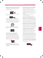 3
3
-
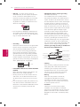 4
4
-
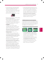 5
5
-
 6
6
-
 7
7
-
 8
8
-
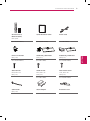 9
9
-
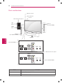 10
10
-
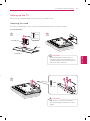 11
11
-
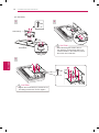 12
12
-
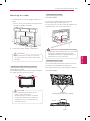 13
13
-
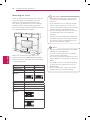 14
14
-
 15
15
-
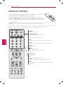 16
16
-
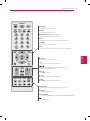 17
17
-
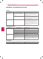 18
18
-
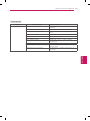 19
19
-
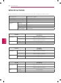 20
20
-
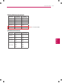 21
21
-
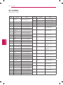 22
22
-
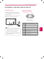 23
23
-
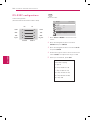 24
24
-
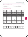 25
25
-
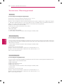 26
26
-
 27
27
-
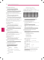 28
28
-
 29
29
-
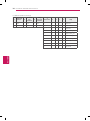 30
30
-
 31
31
-
 32
32
-
 33
33
-
 34
34
-
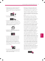 35
35
-
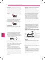 36
36
-
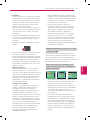 37
37
-
 38
38
-
 39
39
-
 40
40
-
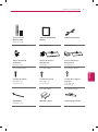 41
41
-
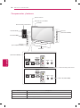 42
42
-
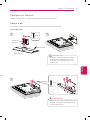 43
43
-
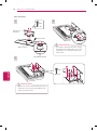 44
44
-
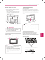 45
45
-
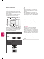 46
46
-
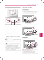 47
47
-
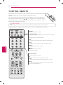 48
48
-
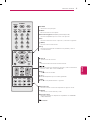 49
49
-
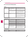 50
50
-
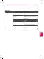 51
51
-
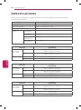 52
52
-
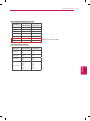 53
53
-
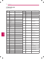 54
54
-
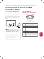 55
55
-
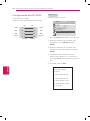 56
56
-
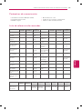 57
57
-
 58
58
-
 59
59
-
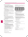 60
60
-
 61
61
-
 62
62
-
 63
63
-
 64
64


LG 32LT360C Manual de usuario
- Categoría
- Televisores LED
- Tipo
- Manual de usuario
- Este manual también es adecuado para
en otros idiomas
- English: LG 32LT360C User manual