
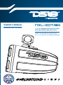
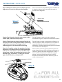
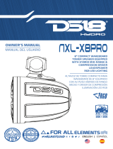
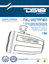
OWNER’S MANUAL
MANUAL DEL USUARIO 1.75" VC COMPRESSION DRIVER TOWER
WITH INTEGRATED RGB LED LIGHTS
TORRE CON DRIVER DE COMPRESIÓN
DE 1.75” CON LUCES LED RGB INTEGRADAS
NXL-XDT/BK

SPECIFICATIONS
SPECIFICATIONS
Nominal Impedance . . . . . . . . . . . . . . . . . . . . . . . . . . . . . . . . . . . . . . . . . . . . . . . . . . . . . . . . . .
RMS Power handling . . . . . . . . . . . . . . . . . . . . . . . . . . . . . . . . . . . . . . . . . . . . . . . . . . . . . . . . . .
MAX Power Handling . . . . . . . . . . . . . . . . . . . . . . . . . . . . . . . . . . . . . . . . . . . . . . . . . . . . . . . . .
Sensitivity (1w/1m) With Horn . . . . . . . . . . . . . . . . . . . . . . . . . . . . . . . . . . . . . . . . . . . . . . . . .
Frequency Response . . . . . . . . . . . . . . . . . . . . . . . . . . . . . . . . . . . . . . . . . . . . . . . . . . . .
Recommended Hi Pass Crossover . . . . . . . . . . . . . . . . . . . . . . . . . . . . . . . . . . . . . . . . . . . . .
BODY / FEATURES
Enclosure Material . . . . . . . . . . . . . . . . . . . . . . . . . . . . . . . . . . . . . . . . . . . . . . . . .
Marine Grade Type . . . . . . . . . . . . . . . . . . . . . . . . . . . . . . . . . . . . . . . . . . . . . . . . . .
RGB LED Lighting: . . . . . . . . . . . . . . . . . . . . . . . . . . . . . . . . . . . Acrylic Ring Lighting and RGB LED
Back Logo with 6 Core Wires f
Horn Type . . . . . . . . . . . . . . . . . . . . . . . . . . . . . . . . . . . . . . . . . . . . . . . . . . . . . . . . . . . . . .
Single or Pair . . . . . . . . . . . . . . . . . . . . . . . . . . . . . . . . . . . . . . . . . . . . . . . . . . . . . . . . . . . . . . . .
Clamps. . . . . . . . . . . . . . . . . . . . . . . . . . . . . . . . . . . . . . . . . . . . . . . . . . . Die-Cast
360 Degree Rotation Mounting, Buried Wi
Mounting Optional, Included NBR
Hardware (Screws, Stop Washers,
Safety Rope, Sc
Front Logo . . . . . . . . . . . . . . . . . . . . . . . . . . . . . . . Yes, Can be Rotated for
Rear Logo . . . . . . . . . . . . . . . . . . . . . . . . . . . . . . . . Yes, Can be Rotated for
Finish . . . . . . . . . . . . . . . . . . . . . . . . . . . . . . . . . . . . . . . . . . . . . . . . . . . . . . . . . . . . . . . .
MOTOR
Voice Coil Diameter. . . . . . . . . . . . . . . . . . . . . . . . . . . . . . . . . . . . . . . . . . . . . . . . . . . . . . . . . . . . .
Voice Coil Former Material . . . . . . . . . . . . . . . . . . . . . . . . . . . . . . . . . . . . . . . . . . . . . . . . . . . .
Winding Material . . . . . . . . . . . . . . . . . . . . . . . . . . . . . . . . . . . . . . . . . . . . . . . . . . . . . . . . . . . . .
Diaphragm Material . . . . . . . . . . . . . . . . . . . . . . . . . . . . . . . . . . . . . . . . . . . . . . . . . . . . . . . . .
Magnet Material . . . . . . . . . . . . . . . . . . . . . . . . . . . . . . . . . . . . . . . . . . . . . . . . . . . . . . . . . . . . . .
Magnet Weight . . . . . . . . . . . . . . . . . . . . . . . . . . . . . . . . . . . . . . . . . . . . . . . . . . . . . . . . . . . . . . . .
Body Material . . . . . . . . . . . . . . . . . . . . . . . . . . . . . . . . . . . . . . . . . . . . . . . . . . . . . . . . . . . .
HORN SPECIFICATIONS
Nominal Diameter. . . . . . . . . . . . . . . . . . . . . . . . . . . . . . . . . . . . . . . . . . . . . . . . . . . . . . . . . . . . . . .
Throat Diameter . . . . . . . . . . . . . . . . . . . . . . . . . . . . . . . . . . . . . . . . . . . . . . . . . . . . . . . . . . . . . . . .
Sound Coverage. . . . . . . . . . . . . . . . . . . . . . . . . . . . . . . . . . . . . . . . . . . . . . . . . . . . . . . . . . . . . . . .
Body Material . . . . . . . . . . . . . . . . . . . . . . . . . . . . . . . . . . . . . . . . . . . . . . . . . . . . . .
Color / Finish . . . . . . . . . . . . . . . . . . . . . . . . . . . . . . . . . . . . . . . . . . . . . . . . . . . . . . . . . . . .
NXL-XDT/BK
1
SPECIFICATIONS
SPECIFICATIONS
Nominal Impedance . . . . . . . . . . . . . . . . . . . . . . . . . . . . . . . . . . . . . . . . . . . . . . . . . . . . . . . . . . 4 ohm
RMS Power handling . . . . . . . . . . . . . . . . . . . . . . . . . . . . . . . . . . . . . . . . . . . . . . . . . . . . . . . . . . 300W
MAX Power Handling . . . . . . . . . . . . . . . . . . . . . . . . . . . . . . . . . . . . . . . . . . . . . . . . . . . . . . . . . 900W
Sensitivity (1w/1m) With Horn . . . . . . . . . . . . . . . . . . . . . . . . . . . . . . . . . . . . . . . . . . . . . . . . . 110dB
Frequency Response . . . . . . . . . . . . . . . . . . . . . . . . . . . . . . . . . . . . . . . . . . . . . . . . . . . . 1KHz-20KHz
Recommended Hi Pass Crossover . . . . . . . . . . . . . . . . . . . . . . . . . . . . . . . . . . . . . . . . . . . . . 1.5KHz
BODY / FEATURES
Enclosure Material . . . . . . . . . . . . . . . . . . . . . . . . . . . . . . . . . . . . . . . . . . . . . . . . . Injection PC + ABS
Marine Grade Type . . . . . . . . . . . . . . . . . . . . . . . . . . . . . . . . . . . . . . . . . . . . . . . . . . IP65 + UV Stable
RGB LED Lighting: . . . . . . . . . . . . . . . . . . . . . . . . . . . . . . . . . . . Acrylic Ring Lighting and RGB LED
Back Logo with 6 Core Wires for Lighting and Speaker
Horn Type . . . . . . . . . . . . . . . . . . . . . . . . . . . . . . . . . . . . . . . . . . . . . . . . . . . . . . . . . . . . . . Circular Long
Single or Pair . . . . . . . . . . . . . . . . . . . . . . . . . . . . . . . . . . . . . . . . . . . . . . . . . . . . . . . . . . . . . . . . . Single
Clamps. . . . . . . . . . . . . . . . . . . . . . . . . . . . . . . . . . . . . . . . . . . . . . . . . . . Die-Cast Adjustable (1"~2")
360 Degree Rotation Mounting, Buried Wire or Open Wire
Mounting Optional, Included NBR Pad And Stainless
Hardware (Screws, Stop Washers, Hexagon wrench,
Safety Rope, Screw fastening Glue)
Front Logo . . . . . . . . . . . . . . . . . . . . . . . . . . . . . . . Yes, Can be Rotated for Correct Angle Display
Rear Logo . . . . . . . . . . . . . . . . . . . . . . . . . . . . . . . . Yes, Can be Rotated for Correct Angle Display
Finish . . . . . . . . . . . . . . . . . . . . . . . . . . . . . . . . . . . . . . . . . . . . . . . . . . . . . . . . . . . . . . . . . . . Matte Black
MOTOR
Voice Coil Diameter. . . . . . . . . . . . . . . . . . . . . . . . . . . . . . . . . . . . . . . . . . . . . . . . . . . . . . . . . . . . . 1.75"
Voice Coil Former Material . . . . . . . . . . . . . . . . . . . . . . . . . . . . . . . . . . . . . . . . . . . . . . . . . . . . Kapton
Winding Material . . . . . . . . . . . . . . . . . . . . . . . . . . . . . . . . . . . . . . . . . . . . . . . . . . . . . . . . . . . . . CCAW
Diaphragm Material . . . . . . . . . . . . . . . . . . . . . . . . . . . . . . . . . . . . . . . . . . . . . . . . . . . . . . . . . Titanium
Magnet Material . . . . . . . . . . . . . . . . . . . . . . . . . . . . . . . . . . . . . . . . . . . . . . . . . . . . . . . . . . . . . . Ferrite
Magnet Weight . . . . . . . . . . . . . . . . . . . . . . . . . . . . . . . . . . . . . . . . . . . . . . . . . . . . . . . . . . . . . . . . 12 Oz
Body Material . . . . . . . . . . . . . . . . . . . . . . . . . . . . . . . . . . . . . . . . . . . . . . . . . . . . . . . . . . . . Aluminum
HORN SPECIFICATIONS
Nominal Diameter. . . . . . . . . . . . . . . . . . . . . . . . . . . . . . . . . . . . . . . . . . . . . . . . . . . . . . . . . . . . . . . 6.5"
Throat Diameter . . . . . . . . . . . . . . . . . . . . . . . . . . . . . . . . . . . . . . . . . . . . . . . . . . . . . . . . . . . . . . . . . . 1"
Sound Coverage. . . . . . . . . . . . . . . . . . . . . . . . . . . . . . . . . . . . . . . . . . . . . . . . . . . . . . . . . . . . . . . . 110°
Body Material . . . . . . . . . . . . . . . . . . . . . . . . . . . . . . . . . . . . . . . . . . . . . . . . . . . . . . Injection PC+ABS
Color / Finish . . . . . . . . . . . . . . . . . . . . . . . . . . . . . . . . . . . . . . . . . . . . . . . . . . . . . . . . . . . . Matte Black
NXL-XDT/BK
1
Impedancia Nominal
Manejo de Potencia RM
Manejo de Potencia MAX
Sensibilidad (1w/1m
Respuesta de Frecuenci
Crosover Paso Alto r
CARCAZA / CARACTERÍSTIC
Material del Gabinet
Tipo de Grado Marin
LED RGB:. . . . . . . . . . . . . . . . . . . . . . . . . . . . . . . . . . . . . . . . . . . . . .
Tipo de Difusor . . . . . . . . . . . . . . . . . . . . . . . . . . . . . . . . . . . . . . . . . . . . . . . . . . . . . . . . . . . . . . . .
Par o Individual. . . . . . . . . . . . . . . . . . . . . . . . . . . . . . . . . . . . . . . . . . . . . . . . . . . . . . . . . . . . . . . .
Abrazaderas. . . . . . . . . . . . . . . . . . . . . . . . . . . . . . . . . . . . . . . . . . . . . . . . . . . . . . . . . .
. . . . . . . . . . . . . . . . . . . . . . . . . . . . .
. . . . . . . . . . . . . . . . . . . . . . . . . . . . . . . . . . . . . . . . . . . . . . . . . . . . . . . . . . . . . . . .
Diámetro de la Bobina
Material de la Bobina
Material del Embobinado
Material de Diafragm
Material del Imán. . . . . . . . . . . . . . . . . . . . . . . . . . . . . . . . . . . . . . . . . . . . . . . . . . . . . . . . . . . . . . . .
Peso del Imán . . . . . . . . . . . . . . . . . . . . . . . . . . . . . . . . . . . . . . . . . . . . . . . . . . . . . . . . . . . . . . . .
Material de la Carca
ESPECIFICACIONES DEL DIFUSOR
Diámetro Nominal . . . . . . . . . . . . . . . . . . . . . . . . . . . . . . . . . . . . . . . . . . . . . . . . . . . . . . . . . . . . . . . .
Diámetro de la Boca
Cobertura de Sonido
Material de la Carca
Color / Acabado . . . . . . . . . . . . . . . . . . . . . . . . . . . . . . . . . . . . . . . . . . . . . . . . . . . . . . . . . . . . . . . .
NXL-XD

. . . . . . . . . . . . . . . . . . . . . . . . . . . . . . . . . . . . . . . . . . . . . . . . . . . . . . . . . . 4 ohm
. . . . . . . . . . . . . . . . . . . . . . . . . . . . . . . . . . . . . . . . . . . . . . . . . . . . . . . . . . 300W
. . . . . . . . . . . . . . . . . . . . . . . . . . . . . . . . . . . . . . . . . . . . . . . . . . . . . . . . . 900W
. . . . . . . . . . . . . . . . . . . . . . . . . . . . . . . . . . . . . . . . . . . . . . . . . 110dB
. . . . . . . . . . . . . . . . . . . . . . . . . . . . . . . . . . . . . . . . . . . . . . . . . . . . 1KHz-20KHz
. . . . . . . . . . . . . . . . . . . . . . . . . . . . . . . . . . . . . . . . . . . . . 1.5KHz
. . . . . . . . . . . . . . . . . . . . . . . . . . . . . . . . . . . . . . . . . . . . . . . . . Injection PC + ABS
. . . . . . . . . . . . . . . . . . . . . . . . . . . . . . . . . . . . . . . . . . . . . . . . . . IP65 + UV Stable
crylic Ring Lighting and RGB LED
or Lighting and Speaker
. . . . . . . . . . . . . . . . . . . . . . . . . . . . . . . . . . . . . . . . . . . . . . . . . . . . . . . . . . . . . . Circular Long
. . . . . . . . . . . . . . . . . . . . . . . . . . . . . . . . . . . . . . . . . . . . . . . . . . . . . . . . . . . . . . . . . Single
Die-Cast Adjustable (1"~2")
ounting, Buried Wire or Open Wire
ounting Optional, Included NBR Pad And Stainless
ashers, Hexagon wrench,
ope, Screw fastening Glue)
Correct Angle Display
Correct Angle Display
. . . . . . . . . . . . . . . . . . . . . . . . . . . . . . . . . . . . . . . . . . . . . . . . . . . . . . . . . . . . . . . . . . . Matte Black
. . . . . . . . . . . . . . . . . . . . . . . . . . . . . . . . . . . . . . . . . . . . . . . . . . . . . . . . . . . . . 1.75"
. . . . . . . . . . . . . . . . . . . . . . . . . . . . . . . . . . . . . . . . . . . . . . . . . . . . Kapton
. . . . . . . . . . . . . . . . . . . . . . . . . . . . . . . . . . . . . . . . . . . . . . . . . . . . . . . . . . . . . CCAW
. . . . . . . . . . . . . . . . . . . . . . . . . . . . . . . . . . . . . . . . . . . . . . . . . . . . . . . . . Titanium
. . . . . . . . . . . . . . . . . . . . . . . . . . . . . . . . . . . . . . . . . . . . . . . . . . . . . . . . . . . . . . Ferrite
. . . . . . . . . . . . . . . . . . . . . . . . . . . . . . . . . . . . . . . . . . . . . . . . . . . . . . . . . . . . . . . . 12 Oz
. . . . . . . . . . . . . . . . . . . . . . . . . . . . . . . . . . . . . . . . . . . . . . . . . . . . . . . . . . . . Aluminum
. . . . . . . . . . . . . . . . . . . . . . . . . . . . . . . . . . . . . . . . . . . . . . . . . . . . . . . . . . . . . . . 6.5"
. . . . . . . . . . . . . . . . . . . . . . . . . . . . . . . . . . . . . . . . . . . . . . . . . . . . . . . . . . . . . . . . . . 1"
. . . . . . . . . . . . . . . . . . . . . . . . . . . . . . . . . . . . . . . . . . . . . . . . . . . . . . . . . . . . . . . . 110°
. . . . . . . . . . . . . . . . . . . . . . . . . . . . . . . . . . . . . . . . . . . . . . . . . . . . . . Injection PC+ABS
. . . . . . . . . . . . . . . . . . . . . . . . . . . . . . . . . . . . . . . . . . . . . . . . . . . . . . . . . . . . Matte Black
ESPECIFICACIONES
ESPECIFICACIONES
Impedancia Nominal. . . . . . . . . . . . . . . . . . . . . . . . . . . . . . . . . . . . . . . . . . . . . . . . . . . . . . . . . . . . . . . . . . . . . . . . 4 ohm
Manejo de Potencia RMS . . . . . . . . . . . . . . . . . . . . . . . . . . . . . . . . . . . . . . . . . . . . . . . . . . . . . . . . . . . . . . . . . . . 300W
Manejo de Potencia MAX . . . . . . . . . . . . . . . . . . . . . . . . . . . . . . . . . . . . . . . . . . . . . . . . . . . . . . . . . . . . . . . . . . . 900W
Sensibilidad (1w/1m) con Difusor. . . . . . . . . . . . . . . . . . . . . . . . . . . . . . . . . . . . . . . . . . . . . . . . . . . . . . . . . . 110dB
Respuesta de Frecuencia . . . . . . . . . . . . . . . . . . . . . . . . . . . . . . . . . . . . . . . . . . . . . . . . . . . . . . . . . . . . . 1Khz-20Khz
Crosover Paso Alto recomendado . . . . . . . . . . . . . . . . . . . . . . . . . . . . . . . . . . . . . . . . . . . . . . . . . . . . . . . . . . 1.5Khz
CARCAZA / CARACTERÍSTICAS
Material del Gabinete. . . . . . . . . . . . . . . . . . . . . . . . . . . . . . . . . . . . . . . . . . . . . . . . . . . . . . . . . . . Inyección PC+ABS
Tipo de Grado Marino. . . . . . . . . . . . . . . . . . . . . . . . . . . . . . . . . . . . . . . . . . . . . . . . . . . . . . . . . . . IP65 + UV Estable
LED RGB:. . . . . . . . . . . . . . . . . . . . . . . . . . . . . . . . . . . . . . . . . . . . . . Iluminación de altavoz LED RGB integrada,
Tipo de Difusor . . . . . . . . . . . . . . . . . . . . . . . . . . . . . . . . . . . . . . . . . . . . . . . . . . . . . . . . . . . . . . . . . . . . . Circular Largo
Par o Individual. . . . . . . . . . . . . . . . . . . . . . . . . . . . . . . . . . . . . . . . . . . . . . . . . . . . . . . . . . . . . . . . . . . . . . . . . Individual
Abrazaderas. . . . . . . . . . . . . . . . . . . . . . . . . . . . . . . . . . . . . . . . . . . . . . . . . . . . . . . . . . Die-Cast Adjustable (1”~2”)
Montaje con rotación de 360 grados,
Montaje con cable enterrado o con cable abierto opcional,
Incluye almohadilla NBR y herrajes de acero inoxidable
(Tornillos, arandelas de tope, llave hexagonal,
Cuerda de seguridad, Pegamento de fijación de tornillos)
Logotipo Delantero . . . . . . . . . . . . . . . . . . . . . . . . . . . Se puede girar para visualizar el ángulo correcto
Logotipo Trasero . . . . . . . . . . . . . . . . . . . . . . . . . . . . . Se puede girar para visualizar el ángulo correcto
Acabado.. . . . . . . . . . . . . . . . . . . . . . . . . . . . . . . . . . . . . . . . . . . . . . . . . . . . . . . . . . . . . . . . . . . . . . . . . . . . . Negro Mate
MOTOR
Diámetro de la Bobina Móvil. . . . . . . . . . . . . . . . . . . . . . . . . . . . . . . . . . . . . . . . . . . . . . . . . . . . . . . . . . . . . . . . 1.75”
Material de la Bobina Móvil. . . . . . . . . . . . . . . . . . . . . . . . . . . . . . . . . . . . . . . . . . . . . . . . . . . . . . . . . . . . . . . Kapton
Material del Embobinado.. . . . . . . . . . . . . . . . . . . . . . . . . . . . . . . . . . . . . . . . . . . . . . . . . . . . . . . . . . . . . . . . . . . CCAW
Material de Diafragma. . . . . . . . . . . . . . . . . . . . . . . . . . . . . . . . . . . . . . . . . . . . . . . . . . . . . . . . . . . . . . . . . . . . . Titanio
Material del Imán. . . . . . . . . . . . . . . . . . . . . . . . . . . . . . . . . . . . . . . . . . . . . . . . . . . . . . . . . . . . . . . . . . . . . . . . . . Ferrita
Peso del Imán . . . . . . . . . . . . . . . . . . . . . . . . . . . . . . . . . . . . . . . . . . . . . . . . . . . . . . . . . . . . . . . . . . . . . . . . . . . . . . 12 Oz
Material de la Carcaza . . . . . . . . . . . . . . . . . . . . . . . . . . . . . . . . . . . . . . . . . . . . . . . . . . . . . . . . . . . . . . . . . Aluminum
ESPECIFICACIONES DEL DIFUSOR
Diámetro Nominal . . . . . . . . . . . . . . . . . . . . . . . . . . . . . . . . . . . . . . . . . . . . . . . . . . . . . . . . . . . . . . . . . . . . . . . . . . . 6.5”
Diámetro de la Boca . . . . . . . . . . . . . . . . . . . . . . . . . . . . . . . . . . . . . . . . . . . . . . . . . . . . . . . . . . . . . . . . . . . . . . . . . . . 1”
Cobertura de Sonido . . . . . . . . . . . . . . . . . . . . . . . . . . . . . . . . . . . . . . . . . . . . . . . . . . . . . . . . . . . . . . . . . . . . . . . . 110°
Material de la Carcaza . . . . . . . . . . . . . . . . . . . . . . . . . . . . . . . . . . . . . . . . . . . . . . . . . . . . . . . . . Inyección PC+ABS
Color / Acabado . . . . . . . . . . . . . . . . . . . . . . . . . . . . . . . . . . . . . . . . . . . . . . . . . . . . . . . . . . . . . . . . . . . . . . Negro Mate
y logotipo trasero LED RGB y cable de 6 hilos
para iluminación y altavoz
NXL-XDT/BK
2
. . . . . . . . . . . . . . . . . . . . . . . . . . . . . . . . . . . . . . . . . . . . . . . . . . . . . . . . . . . . . . . . . . . . . . . 4 ohm
tencia RMS . . . . . . . . . . . . . . . . . . . . . . . . . . . . . . . . . . . . . . . . . . . . . . . . . . . . . . . . . . . . . . . . . . . 300W
tencia MAX . . . . . . . . . . . . . . . . . . . . . . . . . . . . . . . . . . . . . . . . . . . . . . . . . . . . . . . . . . . . . . . . . . . 900W
on Difusor. . . . . . . . . . . . . . . . . . . . . . . . . . . . . . . . . . . . . . . . . . . . . . . . . . . . . . . . . . 110dB
ecuencia . . . . . . . . . . . . . . . . . . . . . . . . . . . . . . . . . . . . . . . . . . . . . . . . . . . . . . . . . . . . . 1Khz-20Khz
omendado . . . . . . . . . . . . . . . . . . . . . . . . . . . . . . . . . . . . . . . . . . . . . . . . . . . . . . . . . . 1.5Khz
CTERÍSTICAS
. . . . . . . . . . . . . . . . . . . . . . . . . . . . . . . . . . . . . . . . . . . . . . . . . . . . . . . . . . . Inyección PC+ABS
. . . . . . . . . . . . . . . . . . . . . . . . . . . . . . . . . . . . . . . . . . . . . . . . . . . . . . . . . . . IP65 + UV Estable
. . . . . . . . . . . . . . . . . . . . . . . . . . . . . . . . . . . . . . . . . . . . . . Iluminación de altavoz LED RGB integrada,
. . . . . . . . . . . . . . . . . . . . . . . . . . . . . . . . . . . . . . . . . . . . . . . . . . . . . . . . . . . . . . . . . . . . . Circular Largo
. . . . . . . . . . . . . . . . . . . . . . . . . . . . . . . . . . . . . . . . . . . . . . . . . . . . . . . . . . . . . . . . . . . . . . . . . Individual
. . . . . . . . . . . . . . . . . . . . . . . . . . . . . . . . . . . . . . . . . . . . . . . . . . . . . . . . . Die-Cast Adjustable (1”~2”)
Montaje con rotación de 360 grados,
Montaje con cable enterrado o con cable abierto opcional,
Incluye almohadilla NBR y herrajes de acero inoxidable
(Tornillos, arandelas de tope, llave hexagonal,
Cuerda de seguridad, Pegamento de fijación de tornillos)
. . . . . . . . . . . . . . . . . . . . . . . . . . . Se puede girar para visualizar el ángulo correcto
. . . . . . . . . . . . . . . . . . . . . . . . . . . . . Se puede girar para visualizar el ángulo correcto
. . . . . . . . . . . . . . . . . . . . . . . . . . . . . . . . . . . . . . . . . . . . . . . . . . . . . . . . . . . . . . . . . . . . . . . . . . . . . Negro Mate
Móvil. . . . . . . . . . . . . . . . . . . . . . . . . . . . . . . . . . . . . . . . . . . . . . . . . . . . . . . . . . . . . . . . 1.75”
Móvil. . . . . . . . . . . . . . . . . . . . . . . . . . . . . . . . . . . . . . . . . . . . . . . . . . . . . . . . . . . . . . . Kapton
aterial del Embobinado.. . . . . . . . . . . . . . . . . . . . . . . . . . . . . . . . . . . . . . . . . . . . . . . . . . . . . . . . . . . . . . . . . . . CCAW
. . . . . . . . . . . . . . . . . . . . . . . . . . . . . . . . . . . . . . . . . . . . . . . . . . . . . . . . . . . . . . . . . . . . . Titanio
. . . . . . . . . . . . . . . . . . . . . . . . . . . . . . . . . . . . . . . . . . . . . . . . . . . . . . . . . . . . . . . . . . . . . . . . . . Ferrita
. . . . . . . . . . . . . . . . . . . . . . . . . . . . . . . . . . . . . . . . . . . . . . . . . . . . . . . . . . . . . . . . . . . . . . . . . . . . . . 12 Oz
. . . . . . . . . . . . . . . . . . . . . . . . . . . . . . . . . . . . . . . . . . . . . . . . . . . . . . . . . . . . . . . . . Aluminum
CIONES DEL DIFUSOR
. . . . . . . . . . . . . . . . . . . . . . . . . . . . . . . . . . . . . . . . . . . . . . . . . . . . . . . . . . . . . . . . . . . . . . . . . . . 6.5”
. . . . . . . . . . . . . . . . . . . . . . . . . . . . . . . . . . . . . . . . . . . . . . . . . . . . . . . . . . . . . . . . . . . . . . . . . . . 1”
. . . . . . . . . . . . . . . . . . . . . . . . . . . . . . . . . . . . . . . . . . . . . . . . . . . . . . . . . . . . . . . . . . . . . . . . 110°
. . . . . . . . . . . . . . . . . . . . . . . . . . . . . . . . . . . . . . . . . . . . . . . . . . . . . . . . . Inyección PC+ABS
. . . . . . . . . . . . . . . . . . . . . . . . . . . . . . . . . . . . . . . . . . . . . . . . . . . . . . . . . . . . . . . . . . . . . . Negro Mate
y logotipo trasero LED RGB y cable de 6 hilos
para iluminación y altavoz
DT/BK
2

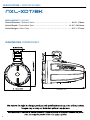
MEASURMENTS / MEDIDAS
Overall Diameter / Diámetro Total. . . . . . . . . . . . . . . . . . . . . . . . . . . . . . . . . . . . . . . . . . . . . . . . 6.93 / 176mm
Overall Depth / Profundidad Total . . . . . . . . . . . . . . . . . . . . . . . . . . . . . . . . . . . . . . . . . . . . 11.16” / 283.4mm
Overall Height / Altura Total . . . . . . . . . . . . . . . . . . . . . . . . . . . . . . . . . . . . . . . . . . . . . . . . . . . . . 10.7” / 271mm
DIMENSIONS / DIMENSIONES
SPECIFICATION / ESPECIFICACIONES
NXL-XDT/BK
3
MEASURMENTS / MEDIDAS
Overall Diameter / Diámetro Total. . . . . . . . . . . . . . . . . . . . . . . . . . . . . . . . . . . . . . . . . . . . . . . .
Overall Depth / Profundidad Total . . . . . . . . . . . . . . . . . . . . . . . . . . . . . . . . . . . . . . . . . . . .
Overall Height / Altura Total . . . . . . . . . . . . . . . . . . . . . . . . . . . . . . . . . . . . . . . . . . . . . . . . . . . . .
DIMENSIONS / DIMENSIONES
SPECIFICATION / ESPECIFICACIONES
NXL-XDT/BK
3
1. Be sure to carefully
instructions before attempting to install these
2. For safety, disconnect the negati
terminal from the battery prior to beginning the
3. For easier assembl
your tools in hand- Drill, Allen set, Crimp,
Soldering iron, Wire
4. Use high quality "W
a reliable installation and to minimize signal
5. Think before you drill! Be ca
drill into gas tank, fuel lines, bra
lines, vacuum lines or electrical wiring when
working on any vehicle.
make sure not cut or drill th
6. Never run wires near fuel lines or power
(if possible). Running the wi
car area provides the best p
7. Avoid running wires
edges. Use rubber or plastic g
protect any wires routed th
8. Make sure that the mounting clamp or "
bracket are tight bef
9. Decide early what type of LED lighting
want (if any) and wir
(NOTE :if you want "Dancing Light" look to the
WiFi or RF or BT remote
The easy way to hav
• An Electric Drill With Bits
Un taladro eléctrico
• Allen / Hex Key / W
Allen / Llave hexagonal / Juego de lla
• Philips Head And S
Destornilladores estándar Phillips
READ BEFORE INS
INSTALLATION E
CONFIGU

. . . . . . . . . . . . . . . . . . . . . . . . . . . . . . . . . . . . . . . . . . . . . . . . 6.93 / 176mm
. . . . . . . . . . . . . . . . . . . . . . . . . . . . . . . . . . . . . . . . . . . . 11.16” / 283.4mm
. . . . . . . . . . . . . . . . . . . . . . . . . . . . . . . . . . . . . . . . . . . . . . . . . . . . . 10.7” / 271mm
ead and understand the
e attempting to install these
onnect the negative battery
om the battery prior to beginning the
, we suggest you have all
our tools in hand- Drill, Allen set, Crimp,
trippers, Heat-shrink, etc.
aterproof' connectors for
eliable installation and to minimize signal
ou drill! Be careful not to cut or
drill into gas tank, fuel lines, brake or hydraulic
acuum lines or electrical wiring when
ehicle. If installing in a boat,
e not cut or drill through the main hull.
es near fuel lines or power
). Running the wires inside the hull or
vides the best protection.
over or through sharp
se rubber or plastic grommets to
outed through metal,
e that the mounting clamp or "L"
e leaving the dock.
9. Decide early what type of LED lighting you
ccordingly
ou want "Dancing Light" look to the
emote controlled LED light box.
e lighting ... YOUR way!)
1. Asegúrese de leer detenidamente y entender las
instrucciones antes de intentar instalar estos
altavoces.
2. Por seguridad, desconecte el terminal negativo de
la batería de la batería antes de empezar la
instalación.
3. Para facilitar el montaje, le sugerimos que tenga
todas sus herramientas a mano: taladro, juego de
llaves Allen, engarzadores, soldador, pelacables,
tubo termo retráctil, etc.
4. Utilice conectores "a prueba de agua" de alta
calidad para una instalación confiable y para
minimizar la pérdida de señal o energía.
5. ¡Piense antes de taladrar! Tenga cuidado de no
cortar ni perforar tanques de gasolina, líneas de
combustible, líneas de frenos o hidráulicas, líneas
de vacío o cableado eléctrico cuando trabaje en
cualquier vehículo. Si se instala en un barco. Tenga
cuidado de no cortar ni perforar el casco principal.
6. Nunca coloque cables cerca de líneas de
combustible o de energía (si es posible). Pasar los
cables dentro del área del casco proporciona la
mejor protección.
7. Evite pasar cables sobre o a través de bordes
afilados. Utilice ojales de goma o plástico para
proteger los cables que atraviesan el metal,
especialmente la torre.
8. Asegúrese de que las abrazaderas de montaje
estén apretadas antes de abandonar la base.
9. Decida con anticipación qué tipo de iluminación
LED que desea usar (si aplica) y conéctelo según
corresponda. (NOTA: si desea "Luces Dinámicas",
utilice un módulo controlador de luz LED (LED-BTC).
La manera más fácil de tener iluminación a tu
manera!)
• An Electric Drill With Bits
on bocas
ench Set
agonal / Juego de llaves
tandard Screw Drivers
es estándar Phillips
• Crimping Tool
Herramienta de presión
• Vom (Electronic Volt Ohm Meter)
Vom (voltímetro electrónico)
• Heat Shrink Tubing And Heat Gun
Tubo termorretráctil y pistola de calor
• Soldering Iron
Soldador
• Electronic (Rosen Not Acid Core) solder
Soldadura electrónica (núcleo de ácido rosen)
TALLATION LEER ANTES DE LA INSTALACIÓN
QUIPMENT / EQUIPO DE INSTALACIÓN
RACIÓN
4
1. Be sure to carefully read and understand the
instructions before attempting to install these
speakers.
2. For safety, disconnect the negative battery
terminal from the battery prior to beginning the
installation.
3. For easier assembly, we suggest you have all
your tools in hand- Drill, Allen set, Crimp,
Soldering iron, Wire Strippers, Heat-shrink, etc.
4. Use high quality "Waterproof' connectors for
a reliable installation and to minimize signal
or power loss.
5. Think before you drill! Be careful not to cut or
drill into gas tank, fuel lines, brake or hydraulic
lines, vacuum lines or electrical wiring when
working on any vehicle. If installing in a boat,
make sure not cut or drill through the main hull.
6. Never run wires near fuel lines or power
(if possible). Running the wires inside the hull or
car area provides the best protection.
7. Avoid running wires over or through sharp
edges. Use rubber or plastic grommets to
protect any wires routed through metal,
especially the tower.
8. Make sure that the mounting clamp or "L"
bracket are tight before leaving the dock.
9. Decide early what type of LED lighting you
want (if any) and wire accordingly
(NOTE :if you want "Dancing Light" look to the
WiFi or RF or BT remote controlled LED light box.
The easy way to have lighting ... YOUR way!)
1. Asegúrese de leer detenidamente y entender las
instrucciones antes de intentar instalar estos
altavoces.
2. Por seguridad, desconecte el terminal negativo de
la batería de la batería antes de empezar la
instalación.
3. Para facilitar el montaje, le sugerimos que tenga
todas sus herramientas a mano: taladro, juego de
llaves Allen, engarzadores, soldador, pelacables,
tubo termo retráctil, etc.
4. Utilice conectores "a prueba de agua" de alta
calidad para una instalación confiable y para
minimizar la pérdida de señal o energía.
5. ¡Piense antes de taladrar! Tenga cuidado de no
cortar ni perforar tanques de gasolina, líneas de
combustible, líneas de frenos o hidráulicas, líneas
de vacío o cableado eléctrico cuando trabaje en
cualquier vehículo. Si se instala en un barco. Tenga
cuidado de no cortar ni perforar el casco principal.
6. Nunca coloque cables cerca de líneas de
combustible o de energía (si es posible). Pasar los
cables dentro del área del casco proporciona la
mejor protección.
7. Evite pasar cables sobre o a través de bordes
afilados. Utilice ojales de goma o plástico para
proteger los cables que atraviesan el metal,
especialmente la torre.
8. Asegúrese de que las abrazaderas de montaje
estén apretadas antes de abandonar la base.
9. Decida con anticipación qué tipo de iluminación
LED que desea usar (si aplica) y conéctelo según
corresponda. (NOTA: si desea "Luces Dinámicas",
utilice un módulo controlador de luz LED (LED-BTC).
La manera más fácil de tener iluminación a tu
manera!)
• An Electric Drill With Bits
Un taladro eléctrico con bocas
• Allen / Hex Key / Wrench Set
Allen / Llave hexagonal / Juego de llaves
• Philips Head And Standard Screw Drivers
Destornilladores estándar Phillips
• Wire Strippers
Pelacables
• Crimping Tool
Herramienta de presión
• Vom (Electronic Volt Ohm Meter)
Vom (voltímetro electrónico)
• Heat Shrink Tubing And Heat Gun
Tubo termorretráctil y pistola de calor
• Soldering Iron
Soldador
• Electronic (Rosen Not Acid Core) solder
Soldadura electrónica (núcleo de ácido rosen)
READ BEFORE INSTALLATION LEER ANTES DE LA INSTALACIÓN
INSTALLATION EQUIPMENT / EQUIPO DE INSTALACIÓN
SETUP / CONFIGURACIÓN
4

1.75” Compression Driver Tower
1 Piece 6 mm Hex wrench Chromed
1 Piece 5 mm Hex wrench Chromed
1 Piece 2.5 mm Hex wrench Chromed
1 Pair NBR Pad For 1.75” Tube
1 Pair NBR Pad For 1.5” Tube
PACKAGING INCLUDES
Torre con Driver de comp
1 llave hexagonal de 6 mm c
1 llave hexagonal de 5 mm c
1 llave hexagonal de 2,5 mm c
1 par de almohadillas NBR de 1.75 "pa
1 par de almohadillas NBR de 1,5 "pa
LA CAJA INCLUYE
NOTE: The stainless steel hardware
supplied with your speakers has been
chosen to resist rust and corrosion. If
the particular hardware supplied will
not work for your installation purposes,
please be sure to use only appropriate
marine grade (stainless steel) mounting
hardware.
NOTA: La tornillería de a
da con sus altavoces ha sido elegida pa
óxido y la corrosión. Si el ha
suministrado no funciona pa
instalación, asegúrese de usar solo ha
montaje apropiado de g
inoxidable).
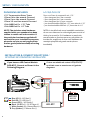
Blue LED (-) / LED Azul (-)
Red LED (-) / LED Rojo (-)
Green LED (-) / LED Verde (-)
Black 12V DC (+) / 12V DC Negro (+)
White Speaker (+) / Altavoz Blanco (+)
Grey Speaker (-) / Altavoz Gris (-)
LED-BTC
INSTALLATION & CONNECTION OPTIONS /
OPCIONES DE CONEXIÓN E INSTALACIÓN
If you have an LED Control Module
(LED-BTC), Connect as Shown in the
Following Diagram:
Si tiene un módulo de
conéctelo como se muest
diagrama:
SETUP / CONFIGURACIÓN
5
1.75” Compression Driver Tower
1 Piece 6 mm Hex wrench Chromed
1 Piece 5 mm Hex wrench Chromed
1 Piece 2.5 mm Hex wrench Chromed
1 Pair NBR Pad For 1.75” Tube
1 Pair NBR Pad For 1.5” Tube
PACKAGING INCLUDES
Torre con Driver de compresión de 1,75 “
1 llave hexagonal de 6 mm cromada
1 llave hexagonal de 5 mm cromada
1 llave hexagonal de 2,5 mm cromada
1 par de almohadillas NBR de 1.75” para tubo de 1.75”
1 par de almohadillas NBR de 1,5” para tubo de 1.5”
LA CAJA INCLUYE
NOTE: The stainless steel hardware
supplied with your speakers has been
chosen to resist rust and corrosion. If
the particular hardware supplied will
not work for your installation purposes,
please be sure to use only appropriate
marine grade (stainless steel) mounting
hardware.
NOTA: La tornillería de acero inoxidable suministra-
da con sus altavoces ha sido elegida para resistir el
óxido y la corrosión. Si el hardware en particular
suministrado no funciona para sus propósitos de
instalación, asegúrese de usar solo hardware de
montaje apropiado de grado marino (acero
inoxidable).
Blue LED (-) / LED Azul (-)
Red LED (-) / LED Rojo (-)
Green LED (-) / LED Verde (-)
Black 12V DC (+) / 12V DC Negro (+)
White Speaker (+) / Altavoz Blanco (+)
Grey Speaker (-) / Altavoz Gris (-)
LED-BTC
BATTERY
BATERÍA
INSTALLATION & CONNECTION OPTIONS /
OPCIONES DE CONEXIÓN E INSTALACIÓN
If you have an LED Control Module
(LED-BTC), Connect as Shown in the
Following Diagram:
Si tiene un módulo de control LED (LED-BTC),
conéctelo como se muestra en el siguiente
diagrama:
SETUP / CONFIGURACIÓN
5
/ LED Azul (-)
/ LED
/ LED
/ Alta
• Black wire"BK" connected to battery
• White Color Light "R"; "B" and "G"
connected to battery
• Green Color Light "G" c
• Red Color Light "R" connected to battery
• Blue Color Light "B" connected to
• Purple Color Light "R" and "B"
• Yellow Color Light"R" and "G"
• Cyan Color Light "B" and "G"
To connect without LED
Module (LED-BTC), C
Shown in the Following Diagram:
INSTALLATION & CONN
OPCIONES DE CONEXIÓN E INS

esión de 1,75 "
agonal de 6 mm cromada
agonal de 5 mm cromada
agonal de 2,5 mm cromada
1 par de almohadillas NBR de 1.75 "para tubo de 1.75"
1 par de almohadillas NBR de 1,5 "para tubo de 1.5"
cero inoxidable suministra
es ha sido elegida para resistir el
osión. Si el hardware en particular
ado no funciona para sus propósitos de
ese de usar solo hardware de
rado marino (acero
Si tiene un módulo de control LED (LED-BTC),
omo se muestra en el siguiente
Blue LED (-) / LED Azul (-)
Red LED (-) / LED Rojo (-)
Green LED (-) / LED Verde (-)
Black 12V DC (+) / 12V DC Negro (+)
White Speaker (+) / Altavoz Blanco (+)
Grey Speaker (-) / Altavoz Gris (-)
BATTERY
BATERÍA
• Black wire"BK" connected to battery
Positive (+) 12V
• White Color Light "R"; "B" and "G"
connected to battery Negative (-)
• Green Color Light "G" connected to
battery Negative (-)
• Red Color Light "R" connected to battery
Negative (-)
• Blue Color Light "B" connected to
battery Negative (-)
• Purple Color Light "R" and "B" connected
to battery Negative (-)
• Yellow Color Light"R" and "G" connected
to battery Negative (-)
• Cyan Color Light "B" and "G" connected
to battery Negative (-)
• Cable negro “BK” conectado al positivo de la
batería (+) 12V
• Luz de color blanco “R”; “B” y “G” conectados
al negativo de la batería (-)
• Luz de color verde "G" conectada al negativo
de la batería (-)
• Luz de color roja “R” conectada al negativo de
la batería (-)
• Luz de color azul “B” conectada al negativo
de la batería (-)
• Luz de color púrpura “R” y “B” conectada al
negativo de la batería (-)
• Luz de color amarillo “R” y “G” conectada al
negativo de la batería (-)
• Luz de color cian “B” y “G” conectada al
negativo de la batería (-)
To connect without LED Control
Module (LED-BTC), Connect as
Shown in the Following Diagram:
Para conectarse sin el módulo de control LED
(LED-BTC), conecte como se muestra en el
siguiente diagrama:
INSTALLATION & CONNECTION OPTIONS /
OPCIONES DE CONEXIÓN E INSTALACIÓN
2 2
6
/ LED Azul (-)
ojo (-)
Verde (-)
/ 12V DC Negro (+)
/ Altavoz Blanco (+)
/ Altavoz Gris (-)
BATTERY
BATERÍA
onnected to battery
olor Light "R"; "B" and "G"
egative (-)
onnected to
onnected to battery
onnected to
olor Light "R" and "B" connected
olor Light"R" and "G" connected
olor Light "B" and "G" connected
• Cable negro "BK" conectado al positivo de la
batería (+) 12V
• Luz de color blanco "R"; "B" y "G" conectados
al negativo de la batería (-)
• Luz de color verde "G" conectada al negativo
de la batería (-)
• Luz de color roja "R" conectada al negativo de
la batería (-)
• Luz de color azul "B" conectada al negativo
de la batería (-)
• Luz de color púrpura "R" y "B" conectada al
negativo de la batería (-)
• Luz de color amarillo "R" y "G" conectada al
negativo de la batería (-)
• Luz de color cian "B" y "G" conectada al
negativo de la batería (-)
onnect without LED Control
onnect as
ollowing Diagram:
Para conectarse sin el módulo de control LED
(LED-BTC), conecte como se muestra en el
siguiente diagrama:
ONNECTION OPTIONS /
ONEXIÓN E INSTALACIÓN
2
6

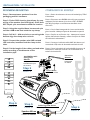
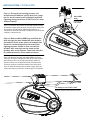
BEGINNING MOUNTING
Step 1: Remove tower speakers from the
packaging and ALL hardware.
Step 2: Find a GOOD location that allows for easy
wiring of the speaker (and LED lights) -PLUS does
NOT impair your movement around the location.
Step 3: Using the supplied 6mm hex wrench spin
out the 4-M8 screw that holds the top clamp
Step 4: Drill 015 - 020 mm hole on mounting tube
bottom align the clamp wire out hole.
Step 5: Connect the speaker wire AMP out and
LED controller, Insulated lock the clamp to the
tube.
Step 6: Cut the length of the rubber pad and wires
outlet according to the diameter of the
installation pipe.
COMENZANDO EL MON
Paso 1: Retire los alta
el hardware.
Paso 2: Encuentre una BUENA ubi
cableado fácil del alta
QUE NO perjudique su m
ubicación.
Paso 3: Con la llave he
gire el tornillo 4-M8 que sujeta la ab
Paso 4: Perfore un orificio de 15ø - 20ø mm en la parte
inferior del tubo de mo
del cable de la abrazade
Paso 5: Conecte el cable de salida AMP del alta
controlador LED, trabe la ab
Paso 6: Corte la longitud de la almohadilla de goma y la
salida de los cables de acue
tubería de instalación.
Cables de Altavoz
Soldadura, tubo termorretráctil
Soldering, Heat shrink
Paso 3
Step 3
Paso 5
Step 5
Speaker Wires
Paso 6
Step 6
304 pernos M8 con
arandela de tope
de resorte
304 M8 Blot with
Spring Stop
Washer
6 Core Wires
6 hilos de núcleo
1.0”
RUBER PAD FOR TUBE
1.25”
1.5”
1.75”
2.0”
2.25”
2.5”
2.75”
3.0”
INSTALLATION / INSTALACIÓN
7
BEGINNING MOUNTING
Step 1: Remove tower speakers from the
packaging and ALL hardware.
Step 2: Find a GOOD location that allows for easy
wiring of the speaker (and LED lights) -PLUS does
NOT impair your movement around the location.
Step 3: Using the supplied 6mm hex wrench spin
out the 4-M8 screw that holds the top clamp
Step 4: Drill 015 - 020 mm hole on mounting tube
bottom align the clamp wire out hole.
Step 5: Connect the speaker wire AMP out and
LED controller, Insulated lock the clamp to the
tube.
Step 6: Cut the length of the rubber pad and wires
outlet according to the diameter of the
installation pipe.
COMENZANDO EL MONTAJE
Paso 1: Retire los altavoces de torre del embalaje y TODO
el hardware.
Paso 2: Encuentre una BUENA ubicación que permita el
cableado fácil del altavoz (y las luces LED) - ADEMÁS
QUE NO perjudique su movimiento alrededor de la
ubicación.
Paso 3: Con la llave hexagonal de 6 mm suministrada,
gire el tornillo 4-M8 que sujeta la abrazadera superior.
Paso 4: Perfore un orificio de 15ø - 20ø mm en la parte
inferior del tubo de montaje y alinee el orificio de salida
del cable de la abrazadera.
Paso 5: Conecte el cable de salida AMP del altavoz y el
controlador LED, trabe la abrazadera aislada al tubo.
Paso 6: Corte la longitud de la almohadilla de goma y la
salida de los cables de acuerdo con el diámetro de la
tubería de instalación.
Cables de Altavoz
Soldadura, tubo termorretráctil
Soldering, Heat shrink
Paso 3
Step 3
Paso 5
Step 5
Speaker Wires
Paso 6
Step 6
Paso 4
Step 4
304 pernos M8 con
arandela de tope
de resorte
304 M8 Blot with
Spring Stop
Washer
6 mm Hex
Wrench
6 Core Wires
6 hilos de núcleo
Llave
hexagonal
de 6 mm
1.0”
RUBER PAD FOR TUBE
1.25”
1.5”
1.75”
2.0”
2.25”
2.5”
2.75”
3.0”
INSTALLATION / INSTALACIÓN
7
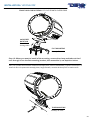
Step 7:Wrap the rubber pad a
align wire out hole According to the diagram.
Step 8: Push the wire into the tube, p
rubber pad, and lock the top clamp.
Step 9: Take down the safety
the pipe, lock the screw gas
ring on the clamp base, and apply sc
fastening glue on the screw be
Step 10: If need be, rotate the spea
dispersion, this easily done
& 4mm hex wrench set scr
clamp base, rotate the spea
desired angle, once there... locking the sc
tight. Avoid vibration, clamp loose!!!
INS

OMENZANDO EL MONTAJE
ces de torre del embalaje y TODO
e una BUENA ubicación que permita el
z (y las luces LED) - ADEMÁS
ovimiento alrededor de la
agonal de 6 mm suministrada,
M8 que sujeta la abrazadera superior.
e un orificio de 15ø - 20ø mm en la parte
taje y alinee el orificio de salida
a.
able de salida AMP del altavoz y el
abe la abrazadera aislada al tubo.
orte la longitud de la almohadilla de goma y la
ables de acuerdo con el diámetro de la
Paso 7
Step 7
Paso 9
Step 9
Rubber Pad
Almohadilla de Goma
Step 7:Wrap the rubber pad around the pipe and
align wire out hole According to the diagram.
Paso 7: Envuelva la almohadilla de goma alrededor de
la tubería y alinee el orificio de salida del cable de
acuerdo con el diagrama.
Step 8: Push the wire into the tube, press on the
rubber pad, and lock the top clamp.
Step 9: Take down the safety rope and hang it on
the pipe, lock the screw gasket safety rope lifting
ring on the clamp base, and apply screw
fastening glue on the screw before locking.
Step 10: If need be, rotate the speakers for best
dispersion, this easily done by locating the 6mm
& 4mm hex wrench set screw on the side of the
clamp base, rotate the speaker/enclosure to the
desired angle, once there... locking the screws
tight. Avoid vibration, clamp loose!!!
Paso 8: Empuje el cable en el tubo, presione la
almohadilla de goma y bloquee la abrazadera superior.
Paso 9: Retire la cuerda de seguridad y cuélgala en la
tubería, bloquee el anillo de elevación de la cuerda de
seguridad de la junta del tornillo en la base de la
abrazadera y aplique pegamento de fijación de tornillos
en el tornillo antes de bloquear
Paso 10: Si es necesario, gire los altavoces para una
mejor dispersión, esto se hace fácilmente ubicando el
tornillo de fijación de la llave hexagonal de 6 mm y 4
mm en el lado de la base de la abrazadera, gire el
altavoz / encaje al ángulo deseado, una vez allí...
bloquear los tornillos para evitar vibración y que se
suelte la abrazadera!!!
INSTALLATION / INSTALACIÓN
8
Paso 9
Step 9
Rubber Pad
Almohadilla de Goma
round the pipe and
ding to the diagram.
Paso 7: Envuelva la almohadilla de goma alrededor de
la tubería y alinee el orificio de salida del cable de
acuerdo con el diagrama.
e into the tube, press on the
rubber pad, and lock the top clamp.
rope and hang it on
et safety rope lifting
ring on the clamp base, and apply screw
ew before locking.
otate the speakers for best
y locating the 6mm
ew on the side of the
er/enclosure to the
e... locking the screws
oid vibration, clamp loose!!!
Paso 8: Empuje el cable en el tubo, presione la
almohadilla de goma y bloquee la abrazadera superior.
Paso 9: Retire la cuerda de seguridad y cuélgala en la
tubería, bloquee el anillo de elevación de la cuerda de
seguridad de la junta del tornillo en la base de la
abrazadera y aplique pegamento de fijación de tornillos
en el tornillo antes de bloquear
Paso 10: Si es necesario, gire los altavoces para una
mejor dispersión, esto se hace fácilmente ubicando el
tornillo de fijación de la llave hexagonal de 6 mm y 4
mm en el lado de la base de la abrazadera, gire el
altavoz / encaje al ángulo deseado, una vez allí...
bloquear los tornillos para evitar vibración y que se
suelte la abrazadera!!!
ALACIÓN
8

Step 11: During the mounting process, you
should have located the spot to drill your tower
bar for the 6 conductor wire (Speaker and RGB
lightning wiring) insertion. Or NOT (see Tie-wrap
solution below)
Paso 11: Durante el proceso de montaje, debería haber
localizado el lugar para perforar la barra de la torre para
la inserción del cable de 6 conductores (altavoz y
cableado de iluminación RGB). O SINO(vea la solución de
corbata a continuación)
Step 12: Remove Wire NBR Plug and Slide the
wire through the hole Snake the wire down to
the bottom of the tower tube in a location that
the wires can be attached to the audio (And
lighting) system. Solder or butt connect the
speaker wire coming from the tower to the
speaker wire to the system. Then heat-shrink it
for added protection from water/moisture.
Paso 12: Retire el enchufe del cable NBR y deslice el
cable por el orificio. Coloque el cable en la parte inferior
del tubo de la torre en un lugar donde los cables se
puedan conectar al sistema de audio (e iluminación).
Suelde o conecte el cable del altavoz que viene de la
torre al cable del altavoz del sistema. Luego, selle con
calor para mayor protección contra el agua / humedad.
INSTALLATION / INSTALACIÓN
9
Wire NBR
Plug
Step 11: During the mounting process, you
should have located the spot to drill your tower
bar for the 6 conductor wire (Speaker and RGB
lightning wiring) insertion. Or NOT (see Tie-wrap
solution below)
Paso 11: Durante el proceso de montaje, debería haber
localizado el lugar para perforar la barra de la torre para
la inserción del cable de 6 conductores (altavoz y
cableado de iluminación RGB). O SINO(vea la solución de
corbata a continuación)
Step 12: Remove Wire NBR Plug and Slide the
wire through the hole Snake the wire down to
the bottom of the tower tube in a location that
the wires can be attached to the audio (And
lighting) system. Solder or butt connect the
speaker wire coming from the tower to the
speaker wire to the system. Then heat-shrink it
for added protection from water/moisture.
Paso 12: Retire el enchufe del cable NBR y deslice el
cable por el orificio. Coloque el cable en la parte inferior
del tubo de la torre en un lugar donde los cables se
puedan conectar al sistema de audio (e iluminación).
Suelde o conecte el cable del altavoz que viene de la
torre al cable del altavoz del sistema. Luego, selle con
calor para mayor protección contra el agua / humedad.
Enchufe del
cable NBR
Tie-Wrap across Tower Tube
Empate a través del tubo de la torre
INSTALLATION / INSTALACIÓN
9
FRONT LOGO CAR R
Step 13: When you want to install a flat mounting,
core through it into the flat mounting brac
Paso 13: Cuando desee instalar media
través de él en el soporte de montaje plano, luego mo

FRONT LOGO CAR ROTATION / EL LOGO FRONTAL PUEDE GIRAR
30 DEGREE
ROTATION
Step 13: When you want to install a flat mounting, remove the clamp and take out the 6
core through it into the flat mounting bracket, then assemble it, see depiction below.
Paso 13: Cuando desee instalar mediante montaje plano, retire la abrazadera y saque el núcleo de 6 a
través de él en el soporte de montaje plano, luego montelo, consulte la descripción a continuación.
Montaje Plano
Rotación
de 30 grados
FLAT MOUNTING
Montaje de Tubo
TUBE MOUNTING
INSTALLATION / INSTALACIÓN
10
TATION / EL LOGO FRONTAL PUEDE GIRAR
ou want to install a flat mounting, remove the clamp and take out the 6
ough it into the flat mounting bracket, then assemble it, see depiction below.
nte montaje plano, retire la abrazadera y saque el núcleo de 6 a
taje plano, luego montelo, consulte la descripción a continuación.
Montaje Plano
FLAT MOUNTING
Montaje de Tubo
TUBE MOUNTING
10

-
 1
1
-
 2
2
-
 3
3
-
 4
4
-
 5
5
-
 6
6
-
 7
7
-
 8
8
-
 9
9
-
 10
10
-
 11
11
-
 12
12


en otros idiomas
- English: DS18 NXL-XDT Owner's manual
Artículos relacionados
-
 DS18 NXL-X8PRO El manual del propietario
-
 DS18 NXL-x10tpneo Marian tower speaker El manual del propietario
-
 DS18 CF-X10TPNEO El manual del propietario
-
 DS18 CF-X10TPNEO El manual del propietario
-
DS18 CF-X8PRO El manual del propietario
-
 DS18 Jvoce El manual del propietario
-
DS18 JVOCE8 Marine Roll Cage Sound Bar Tower Sound System El manual del propietario
-
 DS18 NXL-8M 8 Inch Marine Grade Coaxial Speaker El manual del propietario
-
DS18 NXL-10M El manual del propietario
-
DS18 NXL-10 El manual del propietario


