
1
R. 12/21 856 804
SAMOA Industrial, S.A. · Pol. Ind. Porceyo, I-14 · Camino del Fontán, 831 · 33392 - Gijón - Spain · Tel.: +34 985 381 488 · www.samoaindustrial.com
2021_12_21-11:00
Part No. / Cód. / Réf. / Art. Nr. / Кодировка:
561610 561611 561613
561614 561615 561616
561617
Parts and technical service guide
Guía de servicio técnico y recambio
Guide d’instructions et pièces de rechange
Service- und Ersatzteilhandbuch
Руководство по эксплуатации и обслуживанию
ELECTRIC GEAR PUMP 2
BOMBA ELÉCTRICA DE ENGRANAJES ALTO RENDIMIENTO 4
POMPE ÉLECTRIQUE À ENGRENAGES HAUTE PERFORMANCE 6
ZAHNRADPUMPE EZP 8
ЭЛЕКТРИЧЕСКИЙ ШЕСТЕРЕНЧАТЫЙ НАСОС 10
EN
ES
FR
DE
RU

2856 804 R. 12/21
SAMOA Industrial, S.A. · Pol. Ind. Porceyo, I-14 · Camino del Fontán, 831 · 33392 - Gijón - Spain · Tel.: +34 985 381 488 · www.samoaindustrial.com
2021_12_21-11:00
EN
THREE PHASE SINGLE PHASE
CAPACITOR
Electrical connection
These pumps are distributed without cable (Except for 561616 and
561617 models).
To connect the electric motor to a line, remove the top cover connect the
pump to the line according to fig. 2. Do always employ intallation cables etc.
according to the electrical information given under “Technical Data“
-Electrical information.
Electric pump with sinter steel gears and molted iron body, with direct
coupling to en electric motor, which can be either single phase (models
561617, 561616, 561615, 561614 and 561611) or three phase of high
efficiency IE2 (561613 and 561610).
INSTALLATION
Mechanical installation
These electric pumps must be installed on a horizontal base.
The suction hose diameter should be the same or bigger than the pump
inlet diameter.
See fig. 3 for typical installations with all the recommended accesories
for the pump to operate correctly.
TANK CONNECTION
ATTENTION: Before starting the pump, wet the inside of the pump
body with oil through the inlet and outlet openings. The starting
phase may take from several seconds to a few minutes, depending on
the characteristics of the system.
The distance in height between the oil level and the pump inlet must
not be more than 5 m.
To start the gear pump, make sure that the outlet valve is open.
Pos Description
A Shut-off valve
B Outtlet valve
C Connection adaptor
D Gear pump
E Connetion adaptor
F Filter
G Suction hose
H Shut-off valve
I Adaptor
J Adaptor
Fig. 3
Recommended for pumping high viscosity oil, up to ISO VG 450 cts.
!
Fig. 2

3
R. 12/21 856 804
SAMOA Industrial, S.A. · Pol. Ind. Porceyo, I-14 · Camino del Fontán, 831 · 33392 - Gijón - Spain · Tel.: +34 985 381 488 · www.samoaindustrial.com
2021_12_21-11:00
EN
TROUBLESHOOTING
Symptoms Possible causes Solutions
The pump does not start.
The motor is not powered. Verify electrical connections and thermal protections.
Incorrect supply voltage. Verify rating and motor connections.
Valves on suction and/or discharge pipes closed. Open valves.
The pump does not suck
liquid at startup.
Suction filter clogged. Disassemble and clean the filter.
Presence of air in the suction pipe. Drain pipes. Remove siphons.
Tighten fittings and flanges.
High-pressure losses in the suction line. Increase the pipe diameter.
Remove abrupt variations of section and direction.
Fluid too viscous. Preheat the fluid.
Pressure and/or flow rate
pulses in the
discharge line.
Over voltage and/or over current. Stabilize the mains voltage.
Presence of air in pipes. Drain pipes. Remove siphons.
Tighten fitting and flanges.
Intermittent opening of the by-pass valve. Icrease the valve operating pressure.
Foot valve not working properly. Replace with free ball foot valve.
The pump is noisy
and vibrates.
Presence of air in pipes. Drain pipes. Remove siphons.
Tighten fitting and flanges.
Caivitation. Decrease pressure losses in the suction line.
Change fluid temperature.
Ball bearing and/or bush failure. Replace ball bearing and/or bushes.
The flow rate does not
increase as the speed of
rotation increases.
Pump saturation. Decrease pressure losses in pipes.
Reduce fluid viscosity.
Excessive speed of rotation in relation to the fluid viscosity. Increase the fluid temperature.
Progressive reduction of
the discharge flow rate
and/or pressure, with
constant speed of rotation.
By-pass valve opening. Increase by-pass valve spring preload.
Cavitation. Decrease pressure losses in the suction line.
Change fluid temperature.
By-pass valve opening. Increase by-pass valve spring preload.
Friction increase by thermal effect. Cool the fluid.
Gear shim adjustment to a given clearance gear. Grind read cover.
Decrease in viscosity due to the temperature increase. Decrease the fluid temperature.

4856 804 R. 12/21
SAMOA Industrial, S.A. · Pol. Ind. Porceyo, I-14 · Camino del Fontán, 831 · 33392 - Gijón - Spain · Tel.: +34 985 381 488 · www.samoaindustrial.com
2021_12_21-11:00
ES
INSTALACIÓN
TRIFÁSICO MONOFÁSICO
CONDENSADOR
Conexión eléctrica
La bomba se suministra sin cable (Excepto los modelos 561616 y 561617).
Para conectar el motor a la red, quite la tapa de la caja eléctrica y conecte la
bomba a la línea de acuerdo a la fig. 2. Emplee siempre elementos adecuados
de instalación (ver “Datos técnicos - información eléctrica“).
Bomba eléctrica con engranajes de acero sinterizado y cuerpo de hierro
fundido, con acoplamiento directo a motor eléctrico monofásico (modelos
561617, 561616, 561615, 561614 y 561611) o trifásico de alta eficiencia IE2
(modelos 561613 y 561610).
Instalación mecánica
Estas bombas eléctricas se deben instalar sobre una base horizontal
respetando las condiciones ambientales necesarias para su correcto funcionamiento.
Se recomienda que el diámetro de la manguera de aspiración sea al menos
igual o superior al diámetro de entrada de la bomba.
Ver fig. 3 para instalación típica con todos los accesorios recomendados para
que la bomba opere correctamente.
CONEXIÓN A CISTERNA
ATENCIÓN: Antes de arrancar la bomba, humedezca la parte interior
del cuerpo de la misma con aceite a través de las aperturas. La fase de
arranque podría tardar desde algunos segundos a unos pocos
minutos, dependiendo de las características del sistema.
La distancia en altura entre el nivel de aceite y la entrada de la bomba
no debe ser mayor de 5 m.
Para comenzar a operar con la bomba, asegúrese de que la válvula de
salida está abierta.
Fig. 2
Fig. 3
Indicada para transvase de aceites de viscosidad elevada, hasta ISO VG 450 cts.
Pos Descripción
A Válvula de cierre
B Manguera de salida
C Adaptador de conexión
D Bomba de engranaje
E Adaptador de conexión
F Filtro
G Manguera de succión
H Válvula de cierre
I Adaptador
J Adaptador
!

5
R. 12/21 856 804
SAMOA Industrial, S.A. · Pol. Ind. Porceyo, I-14 · Camino del Fontán, 831 · 33392 - Gijón - Spain · Tel.: +34 985 381 488 · www.samoaindustrial.com
2021_12_21-11:00
ES
ANOMALÍAS Y SOLUCIONES
Síntomas Posibles causas Soluciones
La bomba no arranca.
El motor no tiene corriente. Verifique las conexiones eléctricas.
Voltage incorrecto de la corriente eléctrica. Verifique la potencia y el tipo de las conexiones del motor.
Válvulas de succión y/o tubos de descarga cerrados. Abra las válvulas.
La bomba no aspira
líquido al arrancar.
Filtro de succión obstruido. Desmonte y limpie el filtro.
Presencia de aire en el tubo de succión. Purgue los tubos. Evite los sifones.
Apriete los racores y collarines.
Grandes pérdidas de presión en la línea de succión. Aumente el diámetro del tubo. Evite curvas pronunciadas y cambios
de sección en la tubería.
Fluido demasiado viscoso. Precaliente el fluido.
Presión y/o impulsos
en el nivel de caudal
de la línea de descarga.
Excesivo voltaje y/o corriente. Estabilice el voltaje de la línea.
Presencia de aire en las tuberías. Purgue los tubos. Evite los sifones. Apriete los racores y collarines.
Apertura intermitente de la válvula by-pass. Aumente la presión de trabajo de la válvula.
La válvula de pie funciona incorrectamente. Sustituya válvula de pie. Utilice válvulas de bola libre.
El ratio de flujo no
aumenta cuando lo
hace la velocidad de
rotación.
Saturación de la bomba. Disminuya las pérdidas de presión en tuberías.
Reduzca la viscosidad del fluido.
Excesiva velocidad de rotación en relación a la viscosidad
del fluido. Aumente la temperatura del fluido.
La bomba es ruidosa
y vibra.
Presencia de aire en los tubos. Purgue los tubos. Evite los sifones. Apriete los racores y collarines.
Cavitación. Disminuya las pérdidas de presión en la línea de succión. Cambie la
temperatura del fluido.
Fallo del rodamiento o del cojinete. Reemplace el rodamiendo y/o el cojinete.
Reducción progresiva
del nivel y/o presión
del caudal de descar-
ga, con velocidad de
rotación constante.
Válvula by-pass abierta. Regule el by-pass.
Cavitación. Disminuya las pérdidas de presión en la línea de succión. Cambie la
temperatura del fluido.
Aumento de la fricción por el efecto térmico. Enfríe el fluido.
Desajuste de los engranajes. Ajuste la tapa trasera.
Disminución de la viscosidad del fluido debido al aumento
de temperatura. Disminuya la temperatura del fluido.

6856 804 R. 12/21
SAMOA Industrial, S.A. · Pol. Ind. Porceyo, I-14 · Camino del Fontán, 831 · 33392 - Gijón - Spain · Tel.: +34 985 381 488 · www.samoaindustrial.com
2021_12_21-11:00
FR
INSTALLATION
THREE-PHASE MONOPHASE
CONDENSEUR
Connexion électrique
La pompe est fournie sans câble (sauf 561616 et 561617). Pour raccorder le
moteur au réseau, retirez le couvercle du boîtier électrique et raccordez la
pompe à la ligne selon la fig. 2. Utilisez toujours des éléments d’installation
appropriés (voir “Caractéristiques techniques - informations électriques”).
Électropompe avec engrenages en acier fritté et corps en fonte, avec
accouplement direct à un moteur électrique monophasé (modèles 561617,
561616, 561615, 561614 et 561611) ou triphasé IE2 à haut rendement
(modèles 561613 et 561610).
Installation mécanique
Ces électropompes doivent être installées sur une base horizontale en
respectant les conditions environnementales nécessaires à leur bon
fonctionnement, il est recommandé que le diamètre du tuyau d’aspiration
soit au moins égal ou supérieur au diamètre d’entrée de la pompe. Voir fig. 3
pour une installation typique avec tous les accessoires recommandés pour
que la pompe fonctionne correctement.
CONNEXION AU CITERNE
ATTENTION: Avant de démarrer la pompe, mouillez l’intérieur du
corps de la pompe avec de l’huile par les ouvertures. La phase de
démarrage peut durer de quelques secondes à quelques minutes, en
fonction des caractéristiques du système.
La distance en hauteur entre le niveau d’huile et l’entrée de la pompe
ne doit pas être supérieure à 5 m.
Pour mettre la pompe en marche, assurez-vous que la vanne de sortie
est ouverte.
Fig. 2
Fig. 3
Convient pour le transfert d’huiles à haute viscosité jusqu’à ISO VG 450 cts.
Pos Description
A Vanne d’arrêt
B Tuyau de sortie
C Adaptateur de connexion
D Pompe à engrenages
E Adaptateur de connexion
F Filtre
G Tuyau d’aspiration
H Vanne d’arrêt
I Adaptateur
J Adaptateur
!

7
R. 12/21 856 804
SAMOA Industrial, S.A. · Pol. Ind. Porceyo, I-14 · Camino del Fontán, 831 · 33392 - Gijón - Spain · Tel.: +34 985 381 488 · www.samoaindustrial.com
2021_12_21-11:00
FR
ANOMALIES ET SOLUTIONS
Symptômes Causes possibles Mesures recommandées
La pompe ne
démarre pas.
Le moteur est hors tension. Verifique las conexiones eléctricas.
Tension incorrecte du courant électrique. Vérifiez l’alimentation et le type de connexions du moteur.
Vannes d’aspiration et/ou tuyaux de refoulement fermés. Ouvrez les valves.
La pompe n’aspire pas
de liquide
au démarrage.
Le filtre d’aspiration est bouché. Retirez et nettoyez le filtre.
Présence d’air dans le tuyau d’aspiration. Purge des tuyaux. Évitez les siphons, serrez les raccords et les colliers.
Pertes de pression importantes dans la conduite
d’aspiration.
Augmentez le diamètre du tuyau. Évitez les virages serrés et les
changements de section des tuyaux.
Fluide trop visqueux. Préchauffez le fluide.
Pression et/ou
pulsations dans le
niveau de débit de la
ligne de décharge.
Tension et/ou courant excessifs. Stabiliser la tension de ligne.
Présence d’air dans les tuyaux. Purger les tuyaux. Évitez les siphons. Serrez les raccords et les colliers.
Ouverture intermittente de la valve de by-pass. Augmenter la pression de travail de la valve.
Le clapet de pied fonctionne mal. Remplacer le clapet de pied. Utilisez des vannes à bille libres.
Le débit n’augmente
pas lorsque la vitesse
de rotation augmente.
Saturation de la pompe. Réduire les pertes de pression dans les pipelines.
Réduire la viscosité des fluides.
Vitesse de rotation excessive par rapport à la viscosité
du fluide. Augmentez la température du fluide.
La pompe est bruyante
et vibre.
Présence d’air dans les tubes. Purger les tuyaux. Évitez les siphons. Serrez les raccords et les colliers.
Cavitation. Diminuer les pertes de pression dans la conduite d’aspiration.
Modifiez la température du fluide.
Défaillance du roulement ou du palier. Remplacez le roulement et/ou le palier.
Réduction progressive
du niveau et/ou de
la pression du flux de
décharge, avec une
vitesse de rotation
constante.
Valve de by-pass ouverte. Regule el by-pass.
Cavitation. Diminuer les pertes de pression dans la conduite d’aspiration.
Modifiez la température du fluide.
Augmentation de la friction due à l’effet thermique. Refroidissez le fluide.
Désalignement des engrenages. Serrez le couvercle arrière.
Diminution de la viscosité du fluide due
à l’augmentation de la température. Réduire la température du fluide.

8856 804 R. 12/21
SAMOA Industrial, S.A. · Pol. Ind. Porceyo, I-14 · Camino del Fontán, 831 · 33392 - Gijón - Spain · Tel.: +34 985 381 488 · www.samoaindustrial.com
2021_12_21-11:00
DE
INSTALLATION
DREI PHASEN EINE PHASE
KONDENSATOR
Elektrischer Anschluss
Die Pumpen werden ohne Anschußkabel geliefert (mit Ausnahme ron
561616 und 561617).
Um den Motor an die Stromleitung anzuschließen, öffnen Sie den oberen
Deckel und entfernen das kurze Kabel.
Schließen Sie die Leitung gem. Abbildung 2 an. Beachten Sie bei allen
Elektroinstallationen von Kabeln usw. die entsprechenden Vorschriften,
beschrieben in: “Technische Daten”.
Elektrische Zahnradpumpe mit sinterstahl Zahnräder. Der Motor ist direkt an
der Zahnradpumpe angeflanscht. Die Pumpe ist selbstansaugend und mit
By-Pass-Ventil ausgestattetstehen.
Mechanischer Anschluss
Die Elektropumpe kann auf folgende Art installiert werden: waagrecht an der
Wand oder die Pumpe nach oben oder unten gerichtet zur Wand angebracht.
Beachten Sie die Abbildung unter “Installation” für die übliche Installation mit
dem empfohlenen Zubehör, damit die Pumpe korrekt arbeitet.
INSTALLATIONSBEISPIEL TANKANLAGE
ACHTUNG: Bevor Sie die Pumpe in Betrieb nehmen, anhand der Ein-
und Auslaßstutzen das Innere des Pumpenkörpers mit Öl
benetzen. Das füllen kann, je nach Anlage, einige Sekunden bis
wenige Minuten in Anspruch nehmen.
Die Pumpen sind selbstansaugend und können deshalb auch arbeiten,
wenn die Ansaugleitung leer ist. Die Saughöhe
(Abstand zwischen dem Ölspiegel im Behälter und dem Ansaugstutzen)
darf nicht mehr als 5m betragen.
Stellen Sie sicher, daß bei Inbetriebnahme der Pumpe das Auslaufventil
geöffnet ist.
!
Abb. 2
Abb. 3
Einphasiges Modell mit Art.-Nr.: 561617, 561616, 561615, 561614 und
561611, dreiphasiges Modell mit Art.-Nr.: 561613 und 561610.
Die Pumpe ist geeignet für Öle mit einer Viskosität von 50 bis 450 cSt.
Pos Beschreibung
A Absperrhahn
B Druckschlauch
C Verbindungsnippel
D Pumpe
E Verbindungsnippel
F Filter
G Saugschlauch
H Absperrhahn
I Verbindungsnippel
J Reduziernippel

9
R. 12/21 856 804
SAMOA Industrial, S.A. · Pol. Ind. Porceyo, I-14 · Camino del Fontán, 831 · 33392 - Gijón - Spain · Tel.: +34 985 381 488 · www.samoaindustrial.com
2021_12_21-11:00
DE
PROBLEME UND DEREN LÖSUNGEN
Problem Mögliche Ursache Lösung
Der Motor läuft nicht.
Keine Stromversorgung. Elektr. Anschlüsse prüfen.
Falsche Spannung. Spannung prüfen.
Absperrventile in Saug– und Druckleitung
sind geschlossen. Absperrventile öffnen.
Pumpe saugt nicht an.
Filter in Saugleitung verstopft. Filter reinigen.
Luft in Saugleitung. Verbindungen kontrollieren.
Hoher Unterdruck in der Ansaugleitung. Leitungsquerschnitt erhöhen.
Zu hohe Ölviskosität.
Öltemperatur prüfen, evtl.
Ölanwärmen, um die
Viskosität zu reduzieren.
Druckschwankungen in der
Abgabeleitung.
Überspannung oder Überstrom. Spannung stabilisieren.
Luft in der Druckleitung. Druckleitung öffnen und Luft ablassen.
Verbindungen kontrollieren
In Abständen öffnendes Bypass-Ventil. Druck vom Bypass-Ventil erhöhen.
Fussventil funktioniert nicht korrekt. Fussventil reinigen und eventuell ersetzen.
Erhöhter Geräuschpegel.
Hohlsogbildung, niedriger Ölstand im Fass/Tank. Ansaugdruck reduzieren.
Fehlfunktion des Ventils in der Bypass Leitung. Pumpe laufen lassen bis das Ventil entlüftet ist.
Luftblasen im Öl, Pumpe saugseitig undicht. Saugseit überprüfen.
Geringe oder keine
Förderleistung.
Niedriger Ölstand im Faß/Tank. Behälter auffüllen.
Erhöhten Wiederstand durch Wärme. Flüssigkeit kühle.
Hoher Unterdruck in der Ansaugleitung. Leitungsquerschnitt erhöhen.
Überhöhter Druckverlust im Förderkreislauf
(geöffneter Bypass-Ventil).
Leitungen mit grösserem Durchmesser verwenden oder
Bypass-Ventil nachstellen.
Zu hohe Ölviskosität. Öltemperatur prüfen, evtl.
Öl anwärmen, um die Viskosität zu reduzieren.

10 856 804 R. 12/21
SAMOA Industrial, S.A. · Pol. Ind. Porceyo, I-14 · Camino del Fontán, 831 · 33392 - Gijón - Spain · Tel.: +34 985 381 488 · www.samoaindustrial.com
2021_12_21-11:00
RU
ОПИСАНИЕ
ТРЕХФАЗНЫЙ ОДНОФАЗНЫЙ
КОНДЕНСАТОР
Электрическое подключение
Эти насосы поставляются без кабеля (кроме моделей 561616 и
561617).
Чтобы подключить электродвигатель к линии, снимите верхнюю
крышку, подключите насос к линии согласно рис. 2 Всегда используйте
монтажные кабели в соответствии с электрическими данными,
приведенными в разделе «Технические данные» -
Электрические данные.
Электронасос с шестернями из стали и корпусом из литого железа, с
прямым соединением с электродвигателем, который может быть
однофазным (модели 561617, 561616, 561615, 561614 и 561611) или
трехфазный высокоэффективный IE2 (561613 и 561610).
Монтажная работа
Электронасосы необходимо устанавливать на горизонтальном
основании. Диаметр всасывающего шланга должен быть таким же или
больше диаметра впускного отверстия насоса. См. рис. 3 для типовых
установок со всеми рекомендованными принадлежностями для
правильной работы насоса.
ПОДКЛЮЧЕНИЕ БАКА
ВНИМАНИЕ!: Перед запуском насоса смочите внутреннюю
часть корпуса насоса маслом через впускное и выпускное
отверстия. Фаза запуска может занять от нескольких секунд до
нескольких минут, в зависимости от характеристик системы.
Расстояние по высоте между уровнем масла и входом в насос не
должно превышать 5 м.
Чтобы запустить шестеренчатый насос, убедитесь, что
выпускной клапан открыт.
!
Рис. 2
Рис. 3
Рекомендуется для перекачивания высоковязких масел до ISO VG 450 cts.
Pos Описание
AЗапорный клапан
BВыдыхательный клапан;
CАдаптер подключения
DШестеренчатый насос
EАдаптер подключения
FФильтр
GВсасывающий шланг
HЗапорный клапан
I Адаптер
JАдаптер

11
R. 12/21 856 804
SAMOA Industrial, S.A. · Pol. Ind. Porceyo, I-14 · Camino del Fontán, 831 · 33392 - Gijón - Spain · Tel.: +34 985 381 488 · www.samoaindustrial.com
2021_12_21-11:00
RU
УСТРАНЕНИЕ НЕПОЛАДОК
Проблемы Возможные причины Решения
Насос не запускается.
Двигатель не работает. Проверьте электрические соединения и тепловую защиту.
Неправильное напряжение питания. Проверьте номинальные характеристики и
соединения двигателя.
Клапаны на всасывающей и / или выпускные
трубы закрыты. Откройте клапаны.
Насос не всасывает
жидкость при запуске.
Забит всасывающий фильтр. Разберите и очистите фильтр.
Наличие воздуха во всасывающей трубе. Слейте воду из труб. Снимите сифоны. Затяните
фитинги и фланцы.
Потери высокого давления во всасывающей линии. Увеличьте диаметр трубы. Устраните резкие изменения
сечения и направления.
Жидкость слишком вязкая. Разогрейте жидкость.
Давление и / или
скорость потока
импульсов в линии
нагнетания.
Перенапряжение и / или ток. Стабилизируйте сетевое напряжение.
Наличие воздуха в трубах. Слейте воду. Снимите сифоны. Затяните фитинги и фланцы.
Прерывистое открытие перепускного клапана. Увеличьте рабочее давление клапана.
Нижний клапан не работает должным образом. Замените на свободный шаровой ножной клапан.
Насос шумит и
вибрирует.
Наличие воздуха в трубах. Слейте воду из труб. Снимите сифоны. Затяните
фитинги и фланцы.
Кавитация. Уменьшите потери давления во всасывающей линии.
Измените температуру жидкости.
Отказ шарикового подшипника и / или втулки. Заменить шарикоподшипник и / или втулки.
Скорость потока
не увеличивается с
увеличением скорости
вращения.
Насыщение насоса. Уменьшите потерю давления в трубах.
Уменьшите вязкость жидкости.
Слишком высокая скорость вращения по отношению
к вязкости жидкости. Увеличьте температуру жидкости.
Постепенное снижение
расхода и / или
давления нагнетания
при постоянной скорости
вращения.
Открытие перепускного клапана. Увеличьте предварительную нагрузку пружины
перепускного клапана.
Кавитация. Уменьшите потери давления во всасывающей линии.
Измените температуру жидкости.
Открытие перепускного клапана. Увеличьте предварительную нагрузку пружины
перепускного клапана.
Увеличение трения за счет теплового воздействия. Охладите жидкость.
Регулировка шайбы на заданный зазор шестерни. Заточите поверхность
Снижение вязкости из-за повышения температуры. Уменьшите температуру жидкости.

12 856 804 R. 12/21
SAMOA Industrial, S.A. · Pol. Ind. Porceyo, I-14 · Camino del Fontán, 831 · 33392 - Gijón - Spain · Tel.: +34 985 381 488 · www.samoaindustrial.com
2021_12_21-11:00
Pos. Description Descripción Description
1Main body Cuerpo de la bomba Corps pompe
2Back cover Tapa trasera Couvercle arrière
3Electric motor Cuerpo del motor eléctrico Corps du moteur électrique
4Driving gear Engranaje Engrenage
5Driven gear feather key Chaveta Clé
6O-ring Junta tórica Joint torique
7Socket screw Tornillo Vis
8Driven gear Engranaje Engrenage
9Driven shaft Eje Axe
10 Ring Anillo Anneau
11 Hexagonal head screw Tornillo de cabeza hexagonal Vis à tête hexagonale
12 O-ring Junta tórica Joint torique
13 Seal cover Cierre Fermeture
15 Rotating ring (mech. seal) Anillo giratorio Bague rotative
15a Stationary ring (mech. seal) Anillo fijo Anneau fixe
15b Spring (mech. seal) Muelle Ressort
16 Cap Casquillo Capuchon
17 Regulating screw Tornillo de ajuste Vis de réglage
18 Washer Junta Joint
19 Nut Tuerca Écrou
20 Valve spring Muelle de válvula Ressort de soupape
21 Valve shutter Obturador de válvula Bouchon de valve
22 Dowel pin Pasador Pin
23 Driven gear feather key Chaveta con tornillo de
engranaje Clé avec vis sans fin
26 Bush Casquillo Capuchon
38 Spring clip Perno Spring clip
40 Grub screw Pasador roscado Goupille filetée
Pos. Beschreibung Описание
1Getriebegehäuse Основной корпус
2Getriebedeckel Задняя крышка
3Elektromotor Электродвигатель
4Zahnrad Привод
5Zahnrad - Paßfedernut Шпонка ведомой шестерни
6O-Ring Уплотнительное кольцо
7Inbussschraube Торцевой винт
8Zahnrad Ведомая шестерня
9Zahnrad - Achse Ведомый вал
10 Ring Кольцо
11 Innensechskant-Senkkopfschraube Винт с шестигранной головкой
12 O-Ring Уплотнительное кольцо
13 Dichtungssitz Крышка уплотнения
15 Rotierender Ring (mech. Dichtung) Вращающееся кольцо (мех. уплотнение)
15a Stationäre Ring (mech. Dichtung) Стационарное кольцо (мех. уплотнение)
15b Feder (mech. Dichtung) Пружина (мех. уплотнение)
16 Kappe Колпачок
17 Einstellschraube Регулирующий винт
18 Unterlegscheibe Шайба
19 Mutter гайка
20 Ventilfeder Пружина клапана
21 Ventilverschluss Затвор клапана
22 Stifft Штифт
23 Zahnrad - Paßfedernut Шпонка ведомой шестерни
26 Steckhülse Проходной изолятор
38 Federklemme Установочный винт
40 Gewindestift Установочный винт
EN
DE
FRES
RU
SPARE PARTS/ PIEZAS DE RECAMBIO/ PIÈCES DE RECHANGE /
ERSATZTEILE / ТЕХНИЧЕСКИЕ ДАННЫЕ

13
R. 12/21 856 804
SAMOA Industrial, S.A. · Pol. Ind. Porceyo, I-14 · Camino del Fontán, 831 · 33392 - Gijón - Spain · Tel.: +34 985 381 488 · www.samoaindustrial.com
2021_12_21-11:00
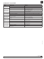
PERFORMANCE / RENDIMIENTO / PERFORMANCE / LEISTUNG / РАБОТА
Part No. / Cód. / Réf.
Art. Nr. / Код.
Flow rate (l/min) / Caudal máximo / Débit maximal
Förderleistung / Скорость потока (л/мин)
Working pressure / Máxima presión de trabajo / Pression de
travail max. / Max. Betriebsdruck / Рабочее давление (бар)
561610 70 10
561611 70 8
561613 50 10
561614 50 8
561615 25 8
561616 15 8
561617 10 20
ELECTRICAL INFORMATION / INFORMACIÓN ELÉCTRICA / INFORMATION ÉLECTRIQUE / MOTOR / ЭЛЕКТРООБОРУДОВАНИЕ
Part No. / Cód. / Réf.
Art. Nr. / Код.
Motor Voltage (V) / Voltaje del motor /
Tension du moteur / Motorspannung /
Напряжение двигателя (V)
Frequency (Hz) / Frecuencia /
Fréquence / Frequenz /
Частота (Hz)
Power (W) / Potencia /
Puissance / Leistung /
Мощность (W)
561610 400 50 1500
561611 220 50/60 2000
561613 400 50 1500
561614 220 50/60 1500
561615 220 50/60 750
561616 220 50/60 550
561617 220 50/60 750
FLUID VISCOSITY / VISCOSIDAD DE FLUIDO / VISCOSITÉ DU FLUIDE / VISKOSITÄT / ВЯЗКОСТЬ ЖИДКОСТИ
Part No. / Cód. / Réf.
Art. Nr. / Код. Viscosity (cSt) / Viscosidad / Viscosité / Viskosität / Вязкость (cSt)
561610 < 450 (cSt)
561611 < 450 (cSt)
561613 < 450 (cSt)
561614 < 450 (cSt)
561615 < 450 (cSt)
561616 < 450 (cSt)
561617 < 450 (cSt)
EN FRES DE RU
TECHNICAL DATA / DATOS TÉCNICOS / CARACTÉRISTIQUES TECHNIQUES /
TECHNISCHE DATEN / ТЕХНИЧЕСКИЕ ДАННЫЕ
EXPLODED VIEW / DESPIECE / PIÈCES DE RECHANGE / TEILELLISTE / ТЕХНИЧЕСКИЕ ДАННЫЕ

14 856 804 R. 12/21
SAMOA Industrial, S.A. · Pol. Ind. Porceyo, I-14 · Camino del Fontán, 831 · 33392 - Gijón - Spain · Tel.: +34 985 381 488 · www.samoaindustrial.com
2021_12_21-11:00
Part No. /
Cód. / Réf.
Art. Nr. /
Код.
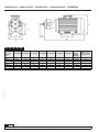
A (mm/мм) B (mm/мм) C (mm/мм) D (mm/мм) E (mm/мм) F (mm/мм) G (mm/мм)
IN/OUT
Ein/Aus
ВХОД/
ВЫХОД
Weight / Peso /
Poids / Gewicht /
(kg) / Вес (кг)
561610 216 455 125 47 140 171 110 1" BSP 23
561611 240 436 125 47 140 171 110 1" BSP 23
561613 220 445 125 47 140 171 110 1" BSP 21
561614 240 445 125 47 140 171 110 1" BSP 21
561615 225 383 100 43 125 152 95,5 3/4" BSP 15
561616 181 330 90 47 112 132 86,5 3/4" BSP 11
561617 212 362 100 47 125 152 95,5 3/4" BSP 15
EN FRES DE RU
DIMENSIONS / DIMENSIONES / DIMENSIONS / ABMESSUNGEN / РАЗМЕРЫ

15
R. 12/21 856 804
SAMOA Industrial, S.A. · Pol. Ind. Porceyo, I-14 · Camino del Fontán, 831 · 33392 - Gijón - Spain · Tel.: +34 985 381 488 · www.samoaindustrial.com
2021_12_21-11:00
NOTES / NOTAS / NOTES / ANMERKUNGEN / ПРИМЕЧАНИЕ

16 856 804 R. 12/21
SAMOA Industrial, S.A. · Pol. Ind. Porceyo, I-14 · Camino del Fontán, 831 · 33392 - Gijón - Spain · Tel.: +34 985 381 488 · www.samoaindustrial.com
2021_12_21-11:00
For SAMOA INDUSTRIAL, S.A.
Por SAMOA INDUSTRIAL, S.A.
Pour SAMOA INDUSTRIAL, S.A.
Für SAMOA INDUSTRIAL, S.A.
От лица компании SAMOA INDUSTRIAL, S.A.
Pedro E. Prallong Álvarez
Production Director
Director de Producción
Directeur de Production
Produktionsleiter
Директор по производству
EC CONFORMITY DECLARATION / DECLARATION CE DE CONFORMIDAD /
DÉCLARATION CE DE CONFORMITÉ / EG-KONFORMITÄTSERKLÄRUNG
SAMOA INDUSTRIAL, S.A., Pol. Ind. Porceyo, I-14 · Camino del Fontán,
831 · 33392 - Gijón - Spain, Spain, declares that the product(s):
561610, 561611, 561613, 561614, 561615, 561616, 561617
conform(s) with the EU Directive(s):
2004/108/EC, 93/68/EC, 2006/42/EC and 2006/95/EC
EN
SAMOA INDUSTRIAL, S.A., Pol. Ind. Porceyo, I-14 · Camino del Fontán,
831 · 33392 - Gijón - España, declara que el(los) producto(s):
561610, 561611, 561613, 561614, 561615, 561616, 561617
cumple(n) con la(s) Directiva(s) de la Unión Europea:
2004/108/EC, 93/68/EC, 2006/42/EC u 2006/95/EC
ES
SAMOA INDUSTRIAL, S.A., Pol. Ind. Porceyo, I-14 · Camino del Fontán,
831 · 33392 - Espagne, déclare que ce(s) produit(s):
561610, 561611, 561613, 561614, 561615, 561616, 561617
est(sont) conforme(s) au(x) Directive(s) de l”Union Européenne:
2004/108/EC, 93/68/EC, 2006/42/EC und 2006/95/EC
SAMOA INDUSTRIAL, S.A., Pol. Ind. Porceyo, I-14 · Camino del Fontán,
831 · 33392 - España, erklärt das das/die Produkt(e):
561610, 561611, 561613, 561614, 561615, 561616, 561617
die Richtlinie(n) der Europäischen Union erfüllen:
2004/108/EC, 93/68/EC, 2006/42/EC und 2006/95/EC
FR DE
Декларация соответствия ЕАЭК:
Декларация соответствия ЕАЭК N RU Д-ES.АБ58.В.02846/20, срок
действия с 11.08.2020 по 12.08.2025, выдан органом по сертификации
продукции «М-ФОНД» ООО
«Агентство по экспертизе и испытаниям продукции»; Адрес 125167,
Россия, г. Москва, ул. Викторенко, дом 16, стр. 1. Телефон:
+74951501658, e-mail: [email protected]. Аттестат аккредитации №RA.
RU.11АБ58 от 07.04.2016 года.
Дата производства указана на маркировке изделия
Транспортировка
Изделие должно транспортироваться в заводской упаковке для
защиты от повреждений и влаги.
Хранение
Изделие должно храниться запакованным, в хорошо проветриваемом
и сухом помещении.
Утилизация
Выполняйте национальные правила утилизации и переработки
отслужившего оборудования, упаковки и принадлежностей.
RU
-
 1
1
-
 2
2
-
 3
3
-
 4
4
-
 5
5
-
 6
6
-
 7
7
-
 8
8
-
 9
9
-
 10
10
-
 11
11
-
 12
12
-
 13
13
-
 14
14
-
 15
15
-
 16
16


Samoa 561614 Instructions Manual
- Tipo
- Instructions Manual
en otros idiomas
- français: Samoa 561614
Artículos relacionados
-
Samoa 561100 Instructions Manual
-
-
-
-
-
-
-
-
-