Bush Hog Multi-Spindle Rotary Cutter El manual del propietario
- Categoría
- Cortadoras de césped
- Tipo
- El manual del propietario

This Operator's Manual is an
integral part of the safe operation
of this machine and must be
maintained with the unit at all
times. READ,
UNDERSTAND, and
FOLLOW the Safety and
Operation Instructions contained
in this manual before operating
the equipment. C01-Cover_A
Important Operating
and Safety Instructions
are found in the Mower
Safety Video that can
be instantly accessed
on the internet at:
www.algqr.com/bve
3308 Pull Model
3308SH
Swing Hitch Model
3308 Lift Model
3308 SERIES
Models 3308, 3308SH
ROTARY MOWER
Rigid Deck / Multi Spindle
Publish Date 01/19 Manual Part No. 50075871
© 2019 Alamo Group Inc.


TABLE OF CONTENTS
SAFETY SECTION........................................................................................................................................... 1-1
GENERAL SAFETY INSTRUCTIONS AND PRACTICES.................................................................................1-2
OPERATOR SAFETY ........................................................................................................................................1-3
GENERAL OPERATING SAFETY.....................................................................................................................1-3
CONNECTION OR DISCONNECTING IMPLEMENT SAFETY ........................................................................1-4
CRUSHING HAZARDS .....................................................................................................................................1-5
THROWN OBJECTS HAZARDS.......................................................................................................................1-6
RUN OVER HAZARDS......................................................................................................................................1-8
PTO ENTANGLEMENT HAZARDS ...................................................................................................................1-9
MOWER BLADE CONTACT HAZARDS..........................................................................................................1-10
HIGH PRESSURE OIL LEAK HAZARDS ........................................................................................................1-11
ELECTRICAL & FIRE HAZARDS ....................................................................................................................1-12
TRANSPORTING HAZARDS ..........................................................................................................................1-13
HAZARDS WITH MAINTENANCE OF IMPLEMENT ......................................................................................1-14
PARTS INFORMATION ...................................................................................................................................1-15
DECAL LOCATION..........................................................................................................................................1-16
DECAL DESCRIPTION ...................................................................................................................................1-18
Federal Laws and Regulations ........................................................................................................................1-26
INTRODUCTION SECTION ..............................................................................................................................2-1
Equipment Specifications ..................................................................................................................................2-3
KEY OPERATION POINTS ...............................................................................................................................2-4
Operating Noise Level/Sound Pressure ............................................................................................................2-4
Limited Warranty................................................................................................................................................2-6
ASSEMBLY SECTION ......................................................................................................................................3-1
DEALER SETUP INSTRUCTIONS ...................................................................................................................3-2
NOTICE (FILL GEARBOXES WITH OIL) ..........................................................................................................3-3
LIFT MODEL ASSEMBLY ..................................................................................................................................3-5
SEMI-MOUNT MODEL ASSEMBLY ..................................................................................................................3-4
SWING HITCH MODEL ASSEMBLY .................................................................................................................3-6
TAILWHEEL ASSEMBLY (DUAL TAILWHEEL BEAM ASSEMBLY) ..................................................................3.7
TAILWHEEL ASSEMBLY (HEAVY DUTY CUSHIONED ASSEMBLY) ..............................................................3-8
PULL TYPE MODEL ASSEMBLY .....................................................................................................................3-9
TIRES & WHEELS FOR PULL MODELS ........................................................................................................3-11
AXLE HEIGHT CONTROL - HYDRAULIC & RATCHET .................................................................................3-12
DRIVELINE ATTACHMENT.............................................................................................................................3-13
OPERATION SECTION.................................................................................................................................... 4-1
OPERATOR REQUIREMENTS ........................................................................................................................4-3
TRACTOR REQUIREMENTS............................................................................................................................4-4
ROPS and Seat Belt ..........................................................................................................................................4-4
Tractor Safety Devices.......................................................................................................................................4-5
Tractor Horsepower ...........................................................................................................................................4-5
3-Point Hitch ......................................................................................................................................................4-5
Drawbar - Pull Type Mower ...............................................................................................................................4-6
Front End Weight...............................................................................................................................................4-6
Power Take Off (PTO)........................................................................................................................................4-6
Tire Spacing.......................................................................................................................................................4-7
GETTING ON & OFF THE TRACTOTR ............................................................................................................4-7
Boarding the Tractor ..........................................................................................................................................4-7
Dismounting the Tractor.....................................................................................................................................4-8

TABLE OF CONTENTS
STARTING THE TRACTOR...............................................................................................................................4-9
CONNECTING THE MOWER TO THE TRACTOR ...........................................................................................4-9
Connecting the Mower-Lift Type and Semi-Mount Type ..................................................................................4-10
3-Point Quick Hitch ..........................................................................................................................................4-10
Connecting Mower - Lift Type (Quick Hitch).....................................................................................................4-11
Safety Tow Chain .............................................................................................................................................4-11
Connecting the Mower-Pull Type.....................................................................................................................4-12
SETTING THE MOWER ..................................................................................................................................4-13
Setting Mower Height- Lift Type.......................................................................................................................4-13
Setting Mowing Height-Pull Type.....................................................................................................................4-14
Setting Deck Pitch ...........................................................................................................................................4-14
DRIVELINE ATTACHMENT .............................................................................................................................4-15
Driveline Length Check....................................................................................................................................4-15
Constant Velocity (CV) Driveline......................................................................................................................4-17
PRE-OPERATION INSPECTION AND SERVICE ...........................................................................................4-18
Tractor Pre-Operation Inspection/Service........................................................................................................4-19
Mower Pre-Operation Inspection/Service ........................................................................................................4-19
Cutting Component Inspection ........................................................................................................................4-23
Blade Bolt Inspection .......................................................................................................................................4-25
DRIVING THE TRACTOR AND IMPLEMENT .................................................................................................4-28
Starting the Tractor ..........................................................................................................................................4-29
Brake and Differential Lock Setting .................................................................................................................4-29
Raising the Mower ...........................................................................................................................................4-30
Driving the Tractor and Mower.........................................................................................................................4-30
Crossing Ditches and Steep Inclines ...............................................................................................................4-31
OPERATING THE TRACTOR AND IMPLEMENT ...........................................................................................4-32
Foreign Debris Hazards...................................................................................................................................4-33
Bystanders/Passersby Precautions .................................................................................................................4-33
Engaging the Power Take Off (PTO) ...............................................................................................................4-34
PTO RPM and Ground Speed .........................................................................................................................4-35
Operating the Mower .......................................................................................................................................4-35
Right of Way (Highway) Mowing......................................................................................................................4-38
Shutting Down the Implement..........................................................................................................................4-39
DISCONNECTING THE MOWER FROM THE TRACTOR .............................................................................4-39
MOWER STORAGE ........................................................................................................................................4-41
TRANSPORTING THE TRACTOR AND IMPLEMENT....................................................................................4-41
Tire and Wheels...............................................................................................................................................4-42
Transporting on Public Roadways ...................................................................................................................4-43
Hauling the Tractor and Implement..................................................................................................................4-44
TROUBLESHOOTING GUIDE ........................................................................................................................4-45
MAINTENANCE SECTION .............................................................................................................................. 5-1
HAZARDS WITH MAINTENANCE OF IMPLEMENT ........................................................................................5-2
Lubrication ........................................................................................................................................................5-3
GEARBOX .........................................................................................................................................................5-7
Driveline Lubrication ..........................................................................................................................................5-7
MAIN DRIVELINE SHIELDS .............................................................................................................................5-9
MAIN CV DRIVELINE SAFETY SHIELD.........................................................................................................5-10
BLADE SERVICING.........................................................................................................................................5-11
BLADE SHARPENING ....................................................................................................................................5-12
BLADE REMOVAL...........................................................................................................................................5-12
BLADE CARRIER REMOVAL .........................................................................................................................5-12
Blade Bolt Inspection .......................................................................................................................................5-13

TABLE OF CONTENTS
BLADE CARRIER INSTALLATION..................................................................................................................5-14
BLADE PAN TIMING .......................................................................................................................................5-14
SLIP CLUTCH .................................................................................................................................................5-15
Slip Clutch Operation Check............................................................................................................................5-15
Slip Clutch Adjustment.....................................................................................................................................5-15
STORAGE .......................................................................................................................................................5-16
PROPER TORQUE FOR FASTENERS ..........................................................................................................5-16


SAFETY SECTION
Safety Section 1-1
© 2019 Alamo Group Inc.

SAFETY
Safety Section 1-2
SAFETY
GENERAL SAFETY INSTRUCTIONS AND PRACTICES
© 2019 Alamo Group Inc.

SAFETY
3308 SERIES 01/19 Safety Section 1-3
© 2019 Alamo Group Inc.
SAFETY

SAFETY
3308 SERIES 01/19 Safety Section 1-4
© 2019 Alamo Group Inc.
SAFETY

SAFETY
3308 SERIES 01/19 Safety Section 1-5
© 2019 Alamo Group Inc.
SAFETY

SAFETY
3308 SERIES 01/19 Safety Section 1-6
© 2019 Alamo Group Inc.
SAFETY

SAFETY
3308 SERIES 01/19 Safety Section 1-7
© 2019 Alamo Group Inc.
SAFETY

SAFETY
3308 SERIES 01/19 Safety Section 1-8
© 2019 Alamo Group Inc.
SAFETY

SAFETY
3308 SERIES 01/19 Safety Section 1-9
© 2019 Alamo Group Inc.
SAFETY

SAFETY
3308 SERIES 01/19 Safety Section 1-10
© 2019 Alamo Group Inc.
SAFETY

SAFETY
3308 SERIES 01/19 Safety Section 1-11
© 2019 Alamo Group Inc.
SAFETY

SAFETY
3308 SERIES 01/19 Safety Section 1-12
© 2019 Alamo Group Inc.
SAFETY

SAFETY
3308 SERIES 01/19 Safety Section 1-13
© 2019 Alamo Group Inc.
SAFETY

SAFETY
3308 SERIES 01/19 Safety Section 1-14
© 2019 Alamo Group Inc.
SAFETY
AVO ID SERIOUS INJURY OR DEATH FROM COMPONENT FAILURE BY KEEPING IMPLEMENT IN
GOOD OPERATING CONDITION IN PERFORMING PROPER SERVICE, REPAIRS AND
MAINTENANCE.
BEFORE PERFORMING SERVICE, REPAIRS AND MAINTENANCE ON THE IMPLEMENT:
SECURE
EQUIPMENT FOR SERVICE
BLOCK OUT POTENTIAL ENERGY HAZARDS; Rotating Parts, Raised Components, Hydraulic Pressure.
• STOP ENGINE
, engage parking brake and allow all moving parts to stop and remove key before dismounting from tractor seat.
•PLACE implement on ground or securely block up raised equipment. Use large blocks on soft or wet soil.
•PUSH and PULL Remote Hydraulic Cylinder lever to relieve hydraulic pressure.
• DISCONNECT IMPLEMENT driveline from tractor PTO Shaft.
WEAR SAFETY GLASSES, PROTECTIVE GLOVES and follow SAFE TY PROCEDURES when performing service, repairs
and maintenance on the implement:
•
Always WEAR protective GLOVES when handling chemicals or worn component with sharp edges.
• Always WEAR GLOVES and SAFETY GLASSES when servicing components
• AVOID CONTACT with hot hydraulic oil tanks, pumps, motors, valves and hose connection surfaces.
• SECURELY support or BLOCK UP raised implement, framework and lifted components before working underneath equipment.
• STOP any implement movements and SHUT-OFF TRACTOR engine before doing any work procedures.
• USE ladder or raised stands to reach high equipment areas inaccessible from ground.
• ENSURE good footing by standing on solid flat surfaces when getting on implement to perform work.
• FOLLOW manufacturer's instructions in handling oils, solvents, cleansers, and other chemical agents.
• DO NOT change any factory set hydraulic calibrations to avoid component or equipment failures.
• DO NOT modify or alter implement, functions or components.
• DO NOT WELD or repair rotating mower components. These may cause vibrations and component failures being thrown from
mower.
PERFORM SERVICE, REPAIRS, LUBRICATION AND MA INTENANCE OUTLINED IN IMPLEMENT MAINTENANCE
SECTION:
•INSPECT
for loose fasteners, worn or broken parts, leaky or loose fittings, missing or broken cotter keys and washers on pins, and
all moving parts for wear.
• REPLACE any worn or broken parts with authorized service parts.
•LUBRICATE unit as specified by lubrication schedule
•NEVER lubricate, adjust or remove material while it is running or in motion.
• TORQUE all bolts and nuts as specified.
BLADE INSPECTION:
• REPLACE
bent, damage, cracked or broken blades immediately with new blades.
• AVOID blade failures and thrown broken blades. DO NOT straighten, weld, or weld hard facing blades.
SAFETY SHIELDS, GUARDS AND SAFETY DEVICES INSPECTION:
•KEEP
all Deflectors, Chain Guards, Steel Guards, Gearbox Shields, and PTO integral shields, Bands, Side Skirts and Skid Shoes
in place and in good condition.
• REPLACE any missing, broken or worn safety shields, guards and safety devices.
Operating, servicing and maintaining this equipment can expose you to chemicals including gasoline,
diesel fuel, lubricants, petroleum products, engine exhaust, carbon monoxide, and phthalates, which are
known to the State of California to cause cancer and birth defects or other reproductive harm. To minimize
exposure, avoid breathing exhaust, do not idle the engine except as necessary, service your vehicle in a
well-ventilated area and wear gloves or wash your hands frequently when servicing your vehicle. Battery
posts, terminals and related accessories contain lead and lead compounds, chemicals known to the state
of California to cause cancer, birth defects or other reproductive harm. For more information go to
www.P65Warnings.ca.gov. This website, operated by California's Office of Environmental Health Hazard
Assessment, provides information about these chemicals and how individuals may be exposed to them.
PN HM01
HAZARDS WITH MAINTENANCE OF IMPLEMENT

SAFETY
3308 SERIES 01/19 Safety Section 1-15
© 2019 Alamo Group Inc.
SAFETY

3308 SERIES 01/19 Safety Section 1-16
© 2019 Alamo Group Inc.
SAFETY
SAFETY
1(
1#
1#
e
1%
w
o
q
e
t
r
y
1^
iu
1!
o
1)
1&
1$
1*
2!
2)
2)

SAFETY
3308 SERIES 01/19 Safety Section 1-17
© 2019 Alamo Group Inc.
SAFETY
ITEM PART NO. QTY LEVEL DESCRIPTION
1. D559 1 WARNING Genuine Bush Hog Parts
2. 50074956 1 NAME 3308
50074957 1 NAME 3308SH
3. D614 2 DANGER Thrown Object Hazard
4. 50028366 1 INFORMATION Warranty
5. D546 3 DANGER Guard Missing-Do Not Operate
6. D547 1 DANGER Rotating D/L Entanglement
7. D553 1 WARNING Multi-Hazard
8. D549 1 DANGER Thrown Object Hazard
9. 50061049 2 LOGO Bush Hog
10. D581 1 INSTRUCT Lubrication Chart
11. 50031212 1 REFLECTOR Amber Reflector
12. NFS 1 SER PLT Serial Number Plate
13. 50031214 2 REFLECTOR Red Reflectors
14. D551 1 WARNING Blade Rotation, CCW
15. D552 1 WARNING Blade Rotation, CW
16. 50035829 1 Canister
17. D813 1 DANGER Multi-Language Safety Decal
18. D454 1 WARNING Crushing Hazard (Decal under deck)
19. *94359 1 REFLECTOR SMV Sign
20. D608 2 WARNING Timing Blade
21. 50074259 1 USA DECAL Made In USA Decal
*Provided By Tractor Manufacturer or Dealer

SAFETY
3308 SERIES 01/19 Safety Section 1-18
© 2019 Alamo Group Inc.
SAFETY

SAFETY
3308 SERIES 01/19 Safety Section 1-19
© 2019 Alamo Group Inc.
SAFETY

SAFETY
3308 SERIES 01/19 Safety Section 1-20
© 2019 Alamo Group Inc.
SAFETY

SAFETY
3308 SERIES 01/19 Safety Section 1-21
© 2019 Alamo Group Inc.
SAFETY

SAFETY
3308 SERIES 01/19 Safety Section 1-22
© 2019 Alamo Group Inc.
SAFETY

SAFETY
3308 SERIES 01/19 Safety Section 1-23
© 2019 Alamo Group Inc.
SAFETY

SAFETY
3308 SERIES 01/19 Safety Section 1-24
© 2019 Alamo Group Inc.
SAFETY

SAFETY
3308 SERIES 01/19 Safety Section 1-25
© 2019 Alamo Group Inc.
SAFETY

SAFETY
3308 SERIES 01/19 Safety Section 1-26
© 2019 Alamo Group Inc.
SAFETY
Federal Laws and Regulations
This section is intended to explain in broad terms the concept and effect of federal laws and regulations concerning
employer and employee equipment operators. This section is not intended as a legal interpretation of the law and
should not be considered as such.
Employer-Employee Operator Regulations
U.S. Public Law 91-596 (The Williams-Steiger Occupational and Health Act of 1970) OSHA
This Act Seeks:
“...to assure so far as possible every working man and woman in the nation safe and healthful working
conditions and to preserve our human resources...”
DUTIES
Sec. 5 (a) Each employer-
(1) shall furnish to each of his employees employment and a place of employment which are free from
recognized hazards that are causing or are likely to cause death or serious physical harm to his employees;
(2) shall comply with occupational safety and health standards promulgated under this Act.
(b)
Each employee shall comply with occupational safety and health standards and all rules, regulations
and
orders issued pursuant to this Act which are applicable to his own actions and conduct.
OSHA Training Requirements
Title 29, Code of Federal Regulations Part 1928.57(a)(6). www.osha.gov
Operator instructions. At the time of initial assignment and at least annually thereafter, the employer shall
instruct every employee who operates an agricultural tractor and implements in the safe operating practices
and servicing of equipment with which they are or will be involved, and of any other practices dictated by the
work environment.
Keep all guards in place when the machine is in operation;
Permit no riders on equipment
Stop engine, disconnect the power source, and wait for all machine movement to stop before servicing,
adjusting, cleaning or unclogging the equipment, except where the machine must be running to be properly
serviced or maintained, in which case the employer shall instruct employees as to all steps
and procedures
which are necessary to safely service or maintain the equipment.
Make sure everyone is clear of machinery before starting the engine, engaging power, or operating the
machine.
Employer Responsibilities:
To ensure employee safety during Tractor and Implement operation, it is the employer’s responsibility to:
1. Train the employee in the proper and safe operation of the Tractor and Implement.
2. Require that the employee read and fully understand the Tractor and Implement Operator’s manual.
3. Permit only qualified and properly trained employees to operate the Tractor and Implement.
4. Maintain the Tractor and Implement in a safe operational condition and maintain all shields and guards on the
equipment.
5. Ensure the Tractor is equipped with a functional ROPS and seat belt and require that the employee operator
securely fasten the safety belt and operate with the ROPS in the raised position at all times.
6. Forbid the employee operator to carry additional riders on the Tractor or Implement.
7. Provide the required tools to maintain the Tractor and Implement in a good safe working condition and provide
the necessary support devices to secure the equipment safely while performing repairs and service.
8. Require that the employee operator stop operation if bystanders or passersby come within 300 feet.
Child Labor Under 16 Years of Age
Some regulations specify that no one under the age of 16 may operate power machinery. It is your responsibility
to know what these regulations are in your own area or situation. (Refer to U.S. Dept. of Labor, Employment Standard
Administration, Wage & Home Division, Child Labor Bulletin #102.)

INTRODUCTION SECTION
Introduction Section 2-1
© 2019 Alamo Group Inc.

INTRODUCTION
3308 SERIES 01/19 Introduction Section 2-2
© 2019 Alamo Group Inc.
INTRODUCTION

INTRODUCTION
3308 SERIES 01/19 Introduction Section 2-3
© 2019 Alamo Group Inc.
INTRODUCTION
The Bush Hog 3308 Series Rotary Mower is designed for medium duty applications such
as weed, grass, corn stalks, and light brush to 2" diameter. These mowers are multi spindle
with two free-swinging blades on each spindle. Free swinging blades reduce the shock of
impact when a stationary object is hit. Additional protection is provided by a slip clutch on
the gearbox input shaft and a rubber element shaft between gearboxes. A round blade holder
allows the mower to “ride over” stumps and similar immovable objects. These Mowers are
attached to the tractor using 3- point Cat I & II standard and quick hitches, and pull hitch,
and CAT I & II semi-mount swing hitch. Standard equipment includes driveline shields, clutch
shields and front and rear discharge shields.
EQUIPMENT SPECIFICATIONS
MODELS 3308 Lift, 3308 Semi Mount, 3308 Pull, 3308SH Swing Hitch
Cutting Width (All Models).................................................................................................8’3”
Overall Width (All Models)...............................................................................................8’10”
Overall Length (Lift, Semi Mount, Swing Hitch).................................................................8’6”
(Pull)........................................................................................................13’6”
Cutting Height ............................................................................................................2” to 13”
Cutting Capacity (maximum)................................................................................................2”
Weight (Lbs.)
Lift.......................................................................................................................1806
Semi Mount ................................................................................................................
Pull .............................................................................................................................
Swing Hitch ................................................................................................................
HP Required (PTO)
Lift......................................................................................................................50HP
Semi Mount .......................................................................................................40HP
Pull ....................................................................................................................40HP
Swing Hitch .......................................................................................................40HP
Swing Hitch Model Offset.............................................................................13” Max. to Right
Blade Tip Speed (540 PTO RPM)........................................................................16,121 FPM
Gearbox Rating (All Models)
Center..............................................................................................................140HP
Outboard .........................................................................................................130HP
Limited Warranty ..............................................................................................5 Year
Driveline ...........................................................................Cat. 4 with1 Year Limited Warranty

INTRODUCTION
3308 SERIES 01/19 Introduction Section 2-4
© 2019 Alamo Group Inc.
INTRODUCTION
3308 Lift Model with Twin
Beam Tailwheel selection and
Double Row Chain enclosers
front and rear.
3308 Pull Model with Heavy
Duty Axle and Single Row
Chain enclosers front and
rear.
3308 Swing Hitch Model with
Heavy Duty Cushioned Axle
and Single Row Chain en-
closers front and rear.
The 3308 Series is shipped from the factory with the Front and Rear Safety Enclousers
assembled to the cutter. The enclousers can be Single Row or Double Row chains on the
front or Single Row Chains, Double Row Chains or a Metal Band to the rear.
These Enclousers should be maintained in good working order and remain attached to
the cutter when operating in conditions may present a Thrown Object Hazard to Humans
or Livestock.

INTRODUCTION
3308 SERIES 01/19 Introduction Section 2-5
© 2019 Alamo Group Inc.
INTRODUCTION
KEY OPERATION POINTS
• Cutting performance and distribution are best when cutter is level from side to side and front to rear.
In extra heavy material, rear chains will allow better discharge and better distribution than solid rear
deflectors or bands.
• Never operate the Mower below full PTO speed of 540 or 1000 rpm.
• Corn should be cut at 5 to 6 mph. If full PTO rpm cannot be maintained, use one lower gear.
Operating Noise Level/Sound Pressure
The sound levels at the operator's ear from the attached machine (rotary cutter) are at least 10 dB(A) below
the levels from typical Agricultural tractors used to power and transport this machine. Therefore, the Noise
emission values given by the OEM of the Agricultural tractor used to power and transport this machine would
be valid when this machine is attached to and operated by that Agricultural tractor in all OEM recommended
applications.
Warranty information
In addition to the standard Limited Warranty shown on the facing page, Bush Hog also provides:
1. A FIVE-YEAR (60 months) LIMITED WARRANTY* on GEARBOX components provided they have
been properly maintained† and have not been subjected to abuse or mis-use except as limited below.
* WARRANTY LIMITATIONS - GEARBOX
A. Warranty is ONE-YEAR (12 MONTHS) for Seals (After one year, seals are considered to be
WEARING PARTS and replacement is the users' responsibility.)
B. Users' Gearboxes may be rebuilt by Bush Hog or replaced by new or rebuilt Gearboxes at the option
of Bush Hog.
2. ONE-YEAR (12 months) LIMITED WARRANTY** on the DRIVELINE components provided they have
been properly maintained† and have not been subjected to abuse or mis-use.
* *WARRANTY LIMITATIONS - DRIVELINE
A. Warranty is ONE-YEAR (12 MONTHS) for DRIVELINE SHIELDS except that evidence of wear from
contact with other parts on the shield voids this warranty.
B. Shield Bearings are wearing parts and are not warrantable.
C. Slip-Clutch Disks are wearing parts and are not warrantable. Evidence of “burning up” Slip Clutch
Plates due to improper adjustment will void warranty on Slip Clutch Parts.
† NOTE - “properly maintained” specifically includes, but is not limited to:
A) Running Gearboxes with the proper amount of the correct lubricant.
B) Adjusting Slip Clutches correctly to provide proper protection for Driveline and Gearbox Components.
C) Properly lubricate all driveline components as specified.
D) Maintaining proper bearing preload on all gearbox shafts.

INTRODUCTION
3308 SERIES 01/19 Introduction Section 2-6
© 2019 Alamo Group Inc.
INTRODUCTION

ASSEMBLY SECTION
Assembly Section 3-1
© 2019 Alamo Group Inc.

ASSEMBLY
3308 SERIES 01/19 Assembly Section 3-2
© 2019 Alamo Group Inc.
ASSEMBLY
DO NOT attempt any assembly while the machine is still attached to the shipping
bracket and standing in the vertical position.
Serious injury or death could occur from the machine falling over.
Assembly must be performed with the machine placed on a hard level surface with
the shipping bracket removed.

ASSEMBLY
3308 SERIES 01/19 Assembly Section 3-3
© 2019 Alamo Group Inc.
ASSEMBLY
NOTICE!
The 3308 is shipped WITHOUT OIL in the
Gearboxes and must be filled before
connecting to the Tractor and placed in
operation!
USE 85W / 140 GEAR OIL
CENTER
GEARBOX
LEFT SIDE
GEARBOX
RIGHT SIDE
GEARBOX
FILLER
PLUG
WITH
DIPSTICK
FILLER
PLUG
WITH
DIPSTICK
OIL FILL
CHECK
PLUG
VENT
PLUG
VENT
PLUG
VENT
PLUG
OIL FILL PROCEDURE
DO NOT OVER FILL GEARBOXES.
1. Remove the oil filler plugs on top the Left and Right side Gearboxes
2. Add Approximately 119 oz.(3.7 QT) of 85W/140 Gear Oil per box.
3. Check with dipstick on the filler plug.
4. Remove the vent plug from the top of the Center Gearbox and the top check plug from the
back of the Center Gearbox. Fill with 2.6 Quarts (2.5L) of 80/140 Gear Oil until oil runs out the
check plug hole.
5. Reinstall the vent plug and the check plug.

ASSEMBLY
3308 SERIES 01/19 Assembly Section 3-4
© 2019 Alamo Group Inc.
ASSEMBLY
3 POINT LIFT MODEL ASSEMBLY
3308 Lift Model with Twin
Beam Tailwheel selection
Heavy Duty
Cushion Axle Selection
FLEX LINK ASSEMBLY
1. Install (2) bushings between the LH and RH Struts using 3/4” x 2-1/2” capscrews and 3/4” lock-
nuts at each location.
2. Place the LH and RH Flex Yokes together and align the slotted holes. Place a Bushing into
the slotted holes.
3. Install the Flex Yokes with Bushing between the Struts so the slanted end is toward the ground
and rest atop the bushing previously installed. Align the holes of the struts and the bushing in
the yokes.
4. Insert a 3/4” x 2-1/2” Capscrew and fasten with a 3/4” Locknut.
5. Tighten all fasteners.
RH Strut
RH Flex Yoke
LH Strut
LH Flex Yoke
Bushing into slotted hole
Bushings
Between Struts
Capscrews 3/4” x 2-1/2”
and Locknuts 3/4”

ASSEMBLY
3308 SERIES 01/19 Assembly Section 3-5
© 2019 Alamo Group Inc.
ASSEMBLY
3 POINT LIFT MODEL ASSEMBLY
SEMI MOUNT MODEL ASSEMBLY
1. Remove the mast from the shipping position and attach the LH and RH Mast to the inside of the inner
mount plates using the rear holes. Install the 2 Strut Bushings in the holes of the Mast. Install using the
5/8” x 2” capscrew, 5/8 SAE flatwasher and 5/8” locknut. Make sure the 5/8” flatwasher is installed to
the inside against the bushing in order to retain it in the mast.
2. Assemble the mast halves by placing the CAT I Quick Hitch Top Bushing between the mast in the lower
hole and install the 3/4” x 4” capscrew and 3/4” locknut.
3. Attach the RH and LH pivot arm halves to the top holes on the mast. Place the mast spacer between
the mast and the pivot arms halves to the outside of the mast. Place a spacer bushing in each pivot
arm and install a 3/4” x 5-1/2” Capscrew and 3/4” Locknut.
4. Install the Driveline Holder to the right hand inside strut using the hole the shipping stand was bolted to.
Use the 1” x 2-1/2” capscrew, 1” lockwasher and 1” hex nut to attach the Driveline Holder.
1. Semi Mount Models do not require the Mast or Struts and Flex Links used on the 3 Point Lift models.
2. Cat.I Hitch Pins with Cat. II Bushings and Spacer Bushings are shipped installed to the lift points of the
cutter.
3. Install the Driveline Holder to the right hand inside strut using the hole the shipping stand was bolted to.
Use the 1” x 2-1/2” capscrew, 1” lockwasher and 1” hex nut to attach the Driveline Holder.
RH Mast
LH Mast
Strut
Bushing
Spacer
Bushing
Spacer
Bushing
5/8” SAE
Flatwasher
5/8” SAE
Locknut
5/8” x 2”
Capscrew
1” x 2-1/2”
Capscrew
1” Lockwasher
1” Hex Nut
Drivline Holder
3/4” x 4”
Capscrew
3/4” x 5-1/2”
Capscrew
Cat I QH Top
Bushing
3/4” Locknut
3/4” Locknut
Mast Spacer
Cat. I Hitch Pin
3 Point Lift and
Semi Mount
Cat. II Bushing
3 Point Lift and
Semi Mount
Spacer Bushing
3 Point Lift and
Semi Mount

ASSEMBLY
3308 SERIES 01/19 Assembly Section 3-6
© 2019 Alamo Group Inc.
ASSEMBLY
SWING HITCH MODEL ASSEMBLY
1. 3308 Swing Hitch Models are shipped with the Swing Hitch assembled to the machine. The hydraulic
cylinder that controls the swing hitch will be installed along with the hydraulic lines. Refer to the detail
below for this installation.
2. Attach the base end of the hydraulic cylinder to the outer cylinder mount and pin in place.
3. Pin the Rod End of the Cylinder to the lug on the LH swing arm.
4. Place the two 90º Hydraulic Fittings in the cylinder ports at the base end and the rod end and tighten.
5. Attach the hydraulic hoses to the 90º elbow fittings and tighten.
90º Hydraulic
Elbows
Hydraulic
Cylinder
Base End
Hydraulic
Cylinder
Rod End
Hydraulic
Hoses
Lug on
Swing Arm

ASSEMBLY
3308 SERIES 01/19 Assembly Section 3-7
© 2019 Alamo Group Inc.
ASSEMBLY
TAILWHEEL INSTALLATION 3 POINT LIFT and SEMI
MOUNT MODELS
DUAL TAILWHEEL BEAM ASSEMBLY
1. Place the height adjusting collar on the tailwheel beam.
2. Attach the height adjusting bracket to the base frame of the machine. Use two each 1/2” x 3-1/4” cap-
screws, 1/2” locknuts per bracket.
3. Place the tailwheel beam between the mounting lugs on the base frame and secure with 1/2” x 4-1/2”
capscrews and 1/2” locknuts.
4. With the tailwheel beam in the slot of the adjusting bracket, slide the adjusting collar to the bracket and
install with two 1/2” x 1-1/4” capscrews and1/2” locknuts.
5. Place the tailwheel through the pivot tube of the tailwheel beam and secure with spiral pin.
6 Apply Grease to pivot tube.
Height Adjusting
Collar
Height Adjusting
Bracket
Tailwheel Beam
Spiral Pin
Tailwheel Assembly
Mounting Lugs
Capscrew 1/2” x1-1/2”
Locknut 1/2”
Capscrew 1/2” x3-1/4”
Locknut 1/2”
Capscrew 1/2” x4-1/2”
Locknut 1/2”

ASSEMBLY
3308 SERIES 01/19 Assembly Section 3-8
© 2019 Alamo Group Inc.
ASSEMBLY
TAILWHEEL INSTALLATION 3 POINT LIFT, SEMI MOUNT
AND SWING HITCH MODELS
HEAVY DUTY CUSHIONED TAILWHEEL ASSEMBLY
1. Remove the H.D. Cushioned Tailwheel assemblies from the shipping position.
2. Place the H.D. Cushioned Tailwheel to the axle assembly as shown n the illustration below and attach
with two U-bolts provided.
3. Install four 3/4” flatwashers, 3/4” lockwashers & 3/4” hex nuts - (2 per U-bolt) and tighten.
4. Remove the lug bolts from the hub and install the wheel assembly making sure the lug bolts are securely
tightened.
Lug Bolts
U-Bolts
Wheel Assembly
H.D. Cushioned
Tailwheel
Assembly
3/4” Hex Nut
3/4” Lockwasher
3/4” Flatwasher
(4 Plc’s.)

ASSEMBLY
3308 SERIES 01/19 Assembly Section 3-9
© 2019 Alamo Group Inc.
ASSEMBLY
PULL MODEL ASSEMBLY
PULL MODEL ASSEMBLY
(Refer to Illustration on next page)
1. Remove Tongue assembly from shipping position and assemble to lower front holes of the hitch plates
(NOTE: be sure the pivot bushings remain inside the pivot tubes of the tongue.) Install the 1” x 8” cap-
screws through the tongue pivot tubes and secure with 1” locknuts.
2. Install the Leveling Rods to the tongue with the clevis that has the slotted holes. Place a 1” flatwasher
to each side against the slotted hole and insert the clevis pin. Secure with the 3/16” x 1-1/2” Cotter Pins.
3. Attach the Leveling Rods to the Axle Lugs with the Clevis Pin and two 3/16” x 1-1/2” Cotter Pins.
4. Place the Axle Arm assemblies to the Axle assembly and secure with (2) U-bolts per Axle Arm and (2)
3/4” Hex Nuts, 3/4” Lockwashers, 3/4” Flatwashers per “U”- Bolt.
5. Remove the Lug Nuts along with the Hub Cap Retainer. Install the Wheel assembly. Replace Hub Cap
Retainer on one of the lug bolts. Install the Lug Nuts and tighten.
6. Hose Holder is placed atop the hole in the plate between the Hitch Plates. Place a 1/2” Flatwasher on
top of the mounting loop of the Hose Holder and insert a 1/2’ x1-1/2” Capscrew through the assembly
securing with a 1/2” Locknut to the underside of the plate.

ASSEMBLY
3308 SERIES 01/19 Assembly Section 3-10
© 2019 Alamo Group Inc.
ASSEMBLY
Steps 1 & 2
Step 3
Step 4
Step 6
Steps 5
PULL MODEL ASSEMBLY

ASSEMBLY
3308 SERIES 01/19 Assembly Section 3-11
© 2019 Alamo Group Inc.
ASSEMBLY
TIRES AND WHEELS
Before installing any tires and wheels make certain the Cutter is jacked up high enough and is securely sup-
ported. When installing laminated or airplane tires, be sure the flat side of the lug nut is against the wheel.
There are only three types of tires that can be used on this cutter DO NOT USE ANY OTHER TYPE OF
TIRE OR WHEEL, such as automutive tires and rims. DO NOT EXCEED THE MAXIMUM SPEED FOR
EACH TYPE OF TIRE. Excessive speed can cause damage to the machine, tire and wheel.
When installing Laminated Tires and Wheels note the direction of travel and curvature of rubber segments
of the tire and install as shown in illustration below. Do not exceed 20 M.P.H. on Lamianted Tires.
Before seperating wheel halves on Airplane Tires,let all the air out ouf the tire by removing the valve core to
make certain no air pressure is left in the tube befor seperating the wheel halves to dismount tire.
*DO NOT LOOSEN WHEEL CLAMP BOLTS BEFORE PRESSURE IS REMOVED FROM TUBE AND
TIRE
TO PREVENT EXPLOSIVE SEPERATION OF WHEEL HALVES WITH POSSIBLE SERIOUS BODILY IN-
JURY.
*Wheel Clamp Bolts
*Wheel Clamp Bolts
Lugnuts
Lugnuts
Place Flatside of
Lug Nut Against Wheel
Place Flatside of
Lug Nut Against Wheel
NOTE SEGMENT
CURVATURE
LAMINATED TIRE
FOAM FILLED TIRE
AIRPLANE TIRE
MAXIMUM INFLATION
PRESSURE 40 PSI
MAXIMUM SPEED 20 MPH

ASSEMBLY
3308 SERIES 01/19 Assembly Section 3-12
© 2019 Alamo Group Inc.
ASSEMBLY
AXLE HEIGHT CONTROL
3308 Models Axle Working Height is determined by either a mechanical Ratchet Assembly
or a single acting Hydraulic Cylinder using Stop Collar adjustments.
HYDRAULIC KIT INSTALLATION
1. Install the Hydraulic Cylinder to the machine with the Rod End of the cylinder to the cylinder lug on the
axle and the Base End of the cylinder to the mount lug on the base frame.
2. Remove the plug on the Rod End of the cylinder and replace with the Breather Plug supplied.
3. Remove the plug at the base end of the cylinder and install the Hydraulic Adaptor 9/16” JIC x 3/4” SAE
with “O” ring in the cylinder.
4. Attach the Hydraulic Hose to the adaptor.
5. There are two adaptors furnished in the kit to adapt the hose to the fitting used in the hydraulic port on
the tractor. Determine which adaptor is required for your application and install to the hydraulic hose.
6. Attach the fitting for the tractor hydraulic port to the hose.
7. Make sure all fittings at tight and plug in hose to tractor hydraulic port.
DO NOT ATTEMPT TO CHARGE THE HYDRAULIC CYLINDER WITHOUT THE BREATHER PLUG
INSTALLED. DAMAGE TO THE CYLINDER MAY OCCUR.
8. Crank the tractor and from the drivers seat cycle the cylinder several times.
9. Extend the Cylinder Rod and install the Stop Collars to support the machine.
Stop Collar Kit
Breather
Plug
Hydraulic Adaptor
9/16”JIC to3/4” SAE
with “O” Ring
Cylinder
Rod End
Cylinder
Base End
RATCHET INSTALLATION
1. Remove the Clevis Pins from the Ratchet Assembly and place the clevis ends to the Axle Lug and the
Mount Lug on the Base Frame.
2. Install the Clevis Pins

ASSEMBLY
3308 SERIES 01/19 Assembly Section 3-13
© 2019 Alamo Group Inc.
ASSEMBLY
DRIVELNE ATTACHMENT
DRIVELINE ATTACHMENT - SLIP CLUTCH
Before starting assembly, make certain that all paint, dirt and grease are removed from
gearbox shaft. To ease assembly, apply a light coat of grease to splines, then assemble.
Do not assemble a driveline without a shield. Entanglement in rotating shafts can kill.
1. Remove tapered pin from splined clutch hub on the end of the driveshaft.
2.
Open the clutch shield inspection holes to expose the gearbox input shaft and give
access to theYoke.
3. Slide the Slip Clutch end of the driveline onto the gearbox input shaft.
4. Make certain that the slip clutch is fully onto the input shaft splines.
5. Align the tapered pin hole in the hub with the grove on the input shaft.
6. Install the tapered pin, washer and locknut. Torque the nut to 30 ft./lbs.


OPERATION SECTION
Operation Section 4-1
© 2019 Alamo Group Inc.

OPERATION
3308 SERIES 01/19 Operation Section 4-2
© 2019 Alamo Group Inc.
OPERATION
BUSH HOG 3308 SERIES ROTARY WOWER
OPERATION INSTRUCTIONS

OPERATION
3308 SERIES 01/19 Operation Section 4-3
© 2019 Alamo Group Inc.
OPERATION

OPERATION
3308 SERIES 01/19 Operation Section 4-4
© 2019 Alamo Group Inc.
OPERATION
Tractor Requirements and Capabilities
• ASABE approved Roll-Over Protective Structure (ROPS) or ROPS cab and seat belt.
• Tractor Safety Devices ......................... Slow Moving Vehicle (SMV) emblem, lighting, PTO master shield
• Tractor Horsepower:
-Minimum .................................. Lift - 50 HP, Pull - 40 HP & Semi-Mount - 40 HP
-Maximum.................................. 90 HP
• Hitch -Lift Type Mower:
- Lifting Capacity........................ Lift - 1850 lbs, Semi-Mount -1845 lbs
- 3-Point Hitch - 3308 ................ CAT I-II and Quick Hitch, CAT I-II Semi-Mount, center pull
3308SH ........... CAT I-II semi-mount offset, center to 13 inches offset
-Hydraulics ................................ Optional
• Pull Type Mower:
-Drawbar .................................... 14” extended length, safety chain attachment point
-Hydraulics ................................. Optional
• Front End Weight ................................ As needed to maintain 20% weight on front axle
• Power Take Off .................................... 540 RPM 6-spline, 1-3/8” diameter output shaft

OPERATION
3308 SERIES 01/19 Oeration Section 4-5
© 2019 Alamo Group Inc.
OPERATION
Tractor Safety Devices
If transporting or operating the tractor and implement near a public roadway, the tractor must be equipped
with proper warning lighting and a Slow Moving Vehicle (SMV) emblem which are clearly visible from the
rear of the unit. Lights and a SMV emblem must be equipped directly on implements if the visibility of the
tractor warning signals are obscured.
Maintain all manufacturer equipped safety shields and guards. Always replace shields and guards that were
removed for access to connect, service, or repair the tractor or implement. Never operate the tractor PTO
with the PTO master shield missing or in the raised position. OPS-U- 0004
Tractor Horsepower
The power required to operate a mower is determined by the tractor PTO horsepower. For most mowing
conditions, the 3308 Series lift mower requires a tractor with at least 50 HP and the semi-mount and pull
type mower require at least 40 HP. Operating the mower with a tractor that does not have adequate power
may damage the tractor engine. Exceeding 90 HP may cause mower damage by overpowering the unit in
heavy cutting conditions.
3-Point Hitch
Lift Type Mower-The tractor 3-point hitch must be
rated to lift at least 1850 lbs.
The Model 3308 Series is designed to be mounted
on a tractor with CAT I or CAT II 3-point or CAT I or
CAT II Quick Hitch.
Refer to the tractor operator’s manual for the cate-
gory of the tractor being used. If the hitch does not
conform to ASABE dimensions, the mower may not
fit or raise properly. Consult an authorized dealer for
possible modification procedures to mount non-con-
forming hitches.
Depending on the hitch category, certain size pins
are used to attach the mower to the tractor. Quick
Hitch requires 1-7/16 diameter lower pin and 1-1/4
diameter upper pin. CAT II hitches require 1-1/8 lower
pins and 1 inch upper pins. CAT III hitches require
1-7/16 lower pins and 1-1/4 upper pin diameters.
Our 3-point Quick Hitch is designed to connect to a
Quick-Attach coupler making mounting and dis-
mounting your mower easier. The 3-Point Quick
Hitch is also designed to connect the mower to a
tractor’s 3-point linkage without the use of a Quick
Attach Coupler.
Top Link
attaches
here
Lift Arms
attach here

OPERATION
3308 SERIES 01/19 Operation Section 4-6
© 2019 Alamo Group Inc.
OPERATION
Drawbar - Pull Type Mower
Front End Weight
Power Take Off (PTO)

OPERATION
3308 SERIES 01/19 Operation Section 4-7
© 2019 Alamo Group Inc.
OPERATION

OPERATION
3308 SERIES 01/19 Operation Section 4-8
© 2019 Alamo Group Inc.
OPERATION

OPERATION
3308 SERIES 01/19 Operation Section 4-9
© 2019 Alamo Group Inc.
OPERATION

OPERATION
3308 SERIES 01/19 Operation Section 4-10
© 2019 Alamo Group Inc.
OPERATION

OPERATION
3308 SERIES 01/19 Operation Section 4-11
© 2019 Alamo Group Inc.
OPERATION

OPERATION
3308 SERIES 01/19 Operation Section 4-12
© 2019 Alamo Group Inc.
OPERATION

OPERATION
3308 SERIES 01/19 Operation Section 4-13
© 2019 Alamo Group Inc.
OPERATION

OPERATION
3308 SERIES 01/19 Operation Section 4-14
© 2019 Alamo Group Inc.
OPERATION
Setting Mowing Height - Pull Type
1. Park the tractor and mower on level ground.
2. Using the hydraulic cylinder or ratchet attached
to the rear axle position the front skid shoes 1”
less off the ground of the desired mowing height.
(Example: If a 3” cut is desired Place the Skid-
shoes at 2” off the ground.) If a hydraulic cylinder
is used for height control, stroke spacers can be
placed on the cylinder rod to maintain a set cut-
ting height.
2. Adjust the two Leveling Rods so the front of the
mower is approximately 3/4” lower than the rear.
3. Level Rod adjustment is achieved by loosening
the lock nut against the clevis and screwing the
Level Rods in or out to set desired setting.
4. Be sure Level rods are equally set to maintain a
level cut.
5. Tighten the Lock Nut against the clevis to main-
tain the setting.
Leveling Rod
Lock Nut
Clevis

OPERATION
3308 SERIES 01/19 Operation Section 4-15
© 2019 Alamo Group Inc.
OPERATION

OPERATION
3308 SERIES 01/19 Operatio Section 4-16
© 2019 Alamo Group Inc.
OPERATION

OPERATION
3308 SERIES 01/19 Operation Section 4-17
© 2019 Alamo Group Inc.
OPERATION
Constant Velocity (CV) Driveline

OPERATION
3308 SERIES 01/19 Operation Section 4-18
© 2019 Alamo Group Inc.
OPERATION

OPERATION
3308 SERIES 01/19 Operation Section 4-19
© 2019 Alamo Group Inc.
OPERATION

OPERATION
3308 SERIES 01/19 Operation Section 4-20
© 2019 Alamo Group Inc.
OPERATION

OPERATION
3308 SERIES 01/19 Operation Section 4-21
© 2019 Alamo Group Inc.
OPERATION

OPERATION
3308 SERIES 01/19 Operation Section 4-22
© 2019 Alamo Group Inc.
OPERATION

OPERATION
3308 SERIES 01/19 Operation Section 4-23
© 2019 Alamo Group Inc.
OPERATION

OPERATION
3308 SERIES 01/19 Operation Section 4-24
© 2019 Alamo Group Inc.
OPERATION

OPERATION
3308 SERIES 01/19 Operation Section 4-25
© 2019 Alamo Group Inc.
OPERATION

OPERATION
3308 SERIES 01/19 Operation Section 4-26
© 2019 Alamo Group Inc.
OPERATION

OPERATION
3308 SERIES 01/19 Operation Section 4-27
© 2019 Alamo Group Inc.
OPERATION

OPERATION
3308 SERIES 01/19 Operation Section 4-28
© 2019 Alamo Group Inc.
OPERATION

OPERATION
3308 SERIES 01/19 Operation Section 4-29
© 2019 Alamo Group Inc.
OPERATION

OPERATION
3308 SERIES 01/19 Operation Section 4-30
© 2019 Alamo Group Inc.
OPERATION

OPERATION
3308 SERIES 01/19 Operation Section 4-31
© 2019 Alamo Group Inc.
OPERATION

OPERATION
3308 SERIES 01/19 Operation Section 4-32
© 2019 Alamo Group Inc.
OPERATION

OPERATION
3308 SERIES 01/19 Operation Section 4-33
© 2019 Alamo Group Inc.
OPERATION

OPERATION
3308 SERIES 01/19 Operation Section 4-34
© 2019 Alamo Group Inc.
OPERATION

OPERATION
3308 SERIES 01/19 Operation Section 4-35
© 2019 Alamo Group Inc.
OPERATION

OPERATION
3308 SERIES 01/19 Operation Section 4-36
© 2019 Alamo Group Inc.
OPERATION

OPERATION
3308 SERIES 01/19 Operation Section 4-37
© 2019 Alamo Group Inc.
OPERATION

OPERATION
3308 SERIES 01/19 Operation Section 4-38
© 2019 Alamo Group Inc.
OPERATION

OPERATION
3308 SERIES 01/19 Operation Section 4-39
© 2019 Alamo Group Inc.
OPERATION

OPERATION
3308 SERIES 01/19 Operation Section 4-40
© 2019 Alamo Group Inc.
OPERATION

OPERATION
3308 SERIES 01/19 Operation Section 4-41
© 2019 Alamo Group Inc.
OPERATION

OPERATION
3308 SERIES 01/19 Operation Section 4-42
© 2019 Alamo Group Inc.
OPERATION

OPERATION
3308 SERIES 01/19 Operation Section 4-43
© 2019 Alamo Group Inc.
OPERATION

OPERATION
3308 SERIES 01/19 Operation Section 4-44
© 2019 Alamo Group Inc.
OPERATION

OPERATION
3308 SERIES 01/19 Operation Section 4-45
© 2019 Alamo Group Inc.
OPERATION

OPERATION
3308 SERIES 01/19 Operation Section 4-46
© 2019 Alamo Group Inc.
OPERATION

MAINTENANCE SECTION
Maintenance Section 5-1
© 2019 Alamo Group Inc.

MAINTENANCE
3308 SERIES 01/19 Maintenance Section 5-2
© 2019 Alamo Group Inc.
MAINTENANCE
HAZARDS WITH MAINTENANCE OF IMPLEMENT

MAINTENANCE
3308 SERIES 01/19 Maintenance Section 5-3
© 2019 Alamo Group Inc.
MAINTENANCE

MAINTENANCE
3308 SERIES 01/19 Maintenance Section 5-4
© 2019 Alamo Group Inc.
MAINTENANCE
3 POINT LIFT and SEMI MOUNT GREASE POINTS
Wheel
Hubs
Caster
Spindles
Caster
Spindles
Gearboxes

MAINTENANCE
3308 SERIES 01/19 Maintenance Section 5-5
© 2019 Alamo Group Inc.
MAINTENANCE
SWING HITCH GREASE POINTS
Both Sides
Swing Arm
Pivot
Points
Wheel
Hubs
Caster
Spindles
Gearboxes

MAINTENANCE
3308 SERIES 01/19 Maintenance Section 5-6
© 2019 Alamo Group Inc.
MAINTENANCE
PULL HITCH GREASE POINTS
Wheel
Hubs
Gearboxes

MAINTENANCE
3308 SERIES 01/19 Maintenance Section 5-7
© 2019 Alamo Group Inc.
MAINTENANCE
CENTER
GEARBOX
LEFT SIDE
GEARBOX
RIGHT SIDE
GEARBOX
FILLER
PLUG
WITH
DIPSTICK
FILLER
PLUG
WITH
DIPSTICK
OIL FILL
CHECK
PLUG
VENT
PLUG
VENT
PLUG
VENT
PLUG
OIL FILL PROCEDURE
DO NOT OVER FILL GEARBOXES!
1. Remove the oil filler plugs on top the Left and Right side Gearboxes
2. Add additional oil (as needed) of 85W/140 Gear Oil.
3. Check with dipstick on the filler plug.
4. Remove the vent plug from the top of the Center Gearbox and the top Oil Fill Check Plug from
the back of the Center Gearbox. Fill with additional oil (as needed) of 85/140 Gear Oil until oil
runs out the Oil Fill Check Plug hole.
5. Reinstall the vent plug and the check plug.
GEARBOX
The gearboxes should not require additional lubricant unless the box is cracked or a seal
is leaking. It is recommended that the oil level be checked after 8 to 10 hours of operation.
If additional oil is required follow the steps below under OIL FILL PROCEDURE.
Use 85W/140 Gear Oil. Under no circumstances should the fill level exceed the fill
level marks on the dipsticks on the outboard boxes or past the Oil Fill Check Plug
on the rear of the Center Gearbox. Capacity of Left and Right Gearbox is Approxi-
mately 119 oz (3.7 QT) per box.
NOTE: Overfilling the Gearboxes can cause a buildup of pressure during operation
and blow out the seals and cause the excess oil to spew from the Vent Plugs!
ATTENTION: If Gearbox suddenly starts making an unusual noise, stop at once, check
for leaks and refill Gearbox as required.

MAINTENANCE
3308 SERIES 01/19 Maintenance Section 5-8
© 2019 Alamo Group Inc.
MAINTENANCE

MAINTENANCE
3308 SERIES 01/19 Maintenance Section 5-9
© 2019 Alamo Group Inc.
MAINTENANCE

MAINTENANCE
3308 SERIES 01/19 Maintenance Section 5-10
© 2019 Alamo Group Inc.
MAINTENANCE

MAINTENANCE
3308 SERIES 01/19 Maintenance Section 5-11
© 2019 Alamo Group Inc.
MAINTENANCE

MAINTENANCE
3308 SERIES 01/19 Maintenance Section 5-12
© 2019 Alamo Group Inc.
MAINTENANCE

MAINTENANCE
3308 SERIES 01/19 Maintenance Section 5-13
© 2019 Alamo Group Inc.
MAINTENANCE
BLADE HOLDER ASSEMBLY
Removal
1. Remove cotter pin and loosen slotted nut on gearbox shaft. Loosen but do not remove the nut until the
blade carrier is loosened.
2. Align blade bolt with access hole in top of cutter deck. Use long bar inserted through blade bolt access
hole with end against blade bar. Strike opposite end of bar with sledge hammer. Rotate blade carrier
180 degrees and repeat process.

MAINTENANCE
3308 SERIES 01/19 Maintenance Section 5-14
© 2019 Alamo Group Inc.
MAINTENANCE

MAINTENANCE
3308 SERIES 01/19 Maintenance Section 5-15
© 2019 Alamo Group Inc.
MAINTENANCE

MAINTENANCE
3308 SERIES 01/19 Maintenance Section 5-16
© 2019 Alamo Group Inc.
MAINTENANCE

MAINTENANCE
3308 SERIES 01/19 Maintenance Section 5-17
© 2019 Alamo Group Inc.
MAINTENANCE

SEGURIDAD
SEGURIDAD
Sección de Seguridad 1-27

SEGURIDAD
Sección de Seguridad 1-26
SEGURIDAD

SEGURIDAD
SEGURIDAD
Sección de Seguridad 1-25

Sección de Seguridad 1-24
SEGURIDAD
SEGURIDAD

Sección de Seguridad 1-23
SEGURIDAD
SEGURIDAD

Sección de Seguridad 1-22
SEGURIDAD
SEGURIDAD

Sección de Seguridad 1-21
SEGURIDAD
SEGURIDAD

Sección de Seguridad 1-20
SEGURIDAD
SEGURIDAD

Sección de Seguridad 1-19
SEGURIDAD
SEGURIDAD

Sección de Seguridad 1-18
SEGURIDAD
SEGURIDAD

Sección de Seguridad 1-17
SEGURIDAD
Descripción de Calcomanía
SEGURIDAD

Sección de Seguridad 1-16
SEGURIDAD
INFORMACIÓN DE PARTES
NOTA: Si necessita un manual completamente en español por favor de ponerse en contacto a;
Translations, dirección 1502 E. Walnut Street Seguin, TX 78155; Fax: (830) 372-9529
INFORMACIÓN DE PARTES
Las cortadoras BUSH HOG usan balanciadas y componentes de systema seleccionado para los portadores
de cuchillas, cuchillas, eje de cortar, navaja, suspensiones de navajas, los rodillos, los componentes de línea
motriz, y cojinetes. Estas partes son echas y probadas a la especificaciones de BUSH HOG. Partes que no
son auténticas no regularmente llegan con estas especificaciones. El uso de partes que no son auténticas
puede reducir el funcionamiento de la cortadora, anular garantias, y presentar un peligro de seguridad. Use
partes de cortadora auténticas de BUSH HOG por economía y seguridad.
(SPBH-1 SP)
CONTACTE A SU DISTRIBUIDOR BUSH HOG
SEGURIDAD

Sección de Seguridad 1-15
SEGURIDAD
RIESGOS CON EL MANTENIMIENTO DEL IMPLEMENTO Continuado
MANTENGA LOS IMPLEMENTOS EN BUENAS CONDICIONES DE
FUNCIONAMIENTO, A TRAVÉS DE UN SERVICIO, REPARACIÓN O
MANTENIMIENTO APROPIADO.
REALICE LAS TAREAS DE SERVICIO, REPARACIÓN, LUBRICACIÓN Y MANTENIMIENTO QUE SE
DESCRIBEN EN LA SECCIÓN DE MANTENIMIENTO DEL IMPLEMENTO:
•
INSPECCIONE el implemento para detectar sujeciones sueltas, partes gastadas o rotas, ajustes sueltos o
con filtraciones, que los pasadores tengan chavetas y arandelas, y las partes móviles para detectar el
desgaste.
•
REEMPLACE todas las partes gastadas o rotas con repuestos autorizados.
•
LUBRIQUE la unidad tal como se especifica en el cronograma de lubricación.
•
NUNCA lubrique, ajuste o quite material mientras el equipo está en funcionamiento o movimiento.
•
AJUSTE todas las tuercas y pernos tal como se especifica.
INSPECCIÓN DE CUCHILLAS:
•
REEMPLACE las cuchillas dobladas, dañadas, agrietadas o rotas inmediatamente por cuchillas nuevas.
•
EVITE fallas de las cuchillas y que vuelen trozos de cuchillas. NO enderece, suelde o suelde con
superficies rígidas.
INSPECCIÓN DE PROTECTORES DE SEGURIDAD, GUARDAS Y DISPOSITIVOS DE SEGURIDAD:
•
MANTENGA en su lugar y en buen estado todos los deflectores, protectores de cadena, protectores de
acero, cubiertas de caja de engranajes, cubiertas integrales de PTO, bandas, faldones laterales y
zapatas antideslizantes.
•
REEMPLACE cualquier protector, cubierta o dispositivo de seguridad faltante, roto o gastado.
Operar, dar servicio y mantener este equipo puede exponerlo a productos químicos como
gasolina, combustible diesel, lubricantes, productos derivados del petróleo, gases de
escape de motores, monóxido de carbono y ftalatos, que el Estado de California considera
que causan cáncer y defectos de nacimiento y otros daños reproductivos. Para minimizar
la exposición, evite respirar el escape, no haga funcionar el motor en ralentí excepto
cuando sea necesario, haga el mantenimiento de su vehículo en un área bien ventilada y
use guantes o lávese las manos frecuentemente cuando realice el mantenimiento de su
vehículo. Los postes de la batería, terminales y accesorios relacionados contienen plomo
y compuestos de plomo, productos químicos que en el estado de California son conocidos
por causar cáncer, defectos de nacimiento y otros daños reproductivos. Para obtener más
información, vaya a www.P65Warnings.ca.gov. Este sitio web, operado por la Oficina de
Evaluación de Peligros para la Salud Ambiental de California, proporciona información
sobre estos químicos y cómo las personas pueden estar expuestas a ellos.
PN HM02 SP
SEGURIDAD

Sección de Seguridad 1-14
SEGURIDAD
RIESGOS CON EL MANTENIMIENTO DEL IMPLEMENTO
SEGURIDAD

Sección de Seguridad 1-13
RIESGOS EN TRANSPORTE
PARA EVITAR LESIONES GRAVES O LA MUERTE AL REMOLCAR O TRANSPORTAR EQUIPOS:
• MANTENGA la velocidad de transporte POR DEBAJO DE 20 millas por hora para mantener el control del equipo.
• REDUZCA LA VELOCIDAD en terreno inclinado, en las curvas y en condiciones de remolque desfavorables.
• NO REMOLQUE camiones u otros vehículos
• USE un tractor de tamaño adecuado y equipado en función del equipo de remolque.
• SIGA todas las reglamentaciones de tránsito locales.
REQUISITOS DEL TRACTOR PARA REMOLCAR O TRANSPORTAR IMPLEMENTOS:
• SÓLO TRANSPORTE en el tractor con el mecanismo ROPS (antivuelco) en posición elevada.
• USE un tractor de tamaño adecuado y equipado, que supere el peso del implemento en al menos un 20%
• MANTENGA EL 20% del peso del tractor en las ruedas frontales para mantener la dirección en forma segura.
ANTES DE TRANSPORTAR O REMOLCAR EL IMPLEMENTO:
INSPECCIÓN DEL TRACTOR:
• VERIFIQUE la dirección y los frenos para asegurarse el correcto funcionamiento y las condiciones adecuadas.
• VERIFIQUE LLEVAR EL AVISO DE SMV, los reflectores y las luces de advertencia para la adecuada operación y
visibilidad detrás de la unidad.
• VERIFIQUE que no haya impedimentos a la visión mientras conduce, en el tractor, la cabina o el implemento,
sentadoenelasientodeltractor.
• AJUSTE su posición de conducción, los espejos y el transporte del implemento para tener una visión clara para
condiciones de conducción y tránsito.
PREPARE EL IMPLEMENTO PARA EL TRANSPORTE O EL REMOLQUE:
• DESAPLIQUE EL PTO
• ELEVE LA CORTADORA
• QUITE todo material cortado que se acumule en la plataforma de la cortadora.
CORTADORA AL REMOLQUE-INSTALE
TRABAS DE TRANSPORTE Y CADENA DE SEGURIDAD:
• INSTALE los paradores o pernos de transporte en el cilindro de eje central.
• AJUSTE LA CADENA DE SEGURIDAD del implemento al tractor.
DETERMINAR LAS CARACTERÍSTICAS DE DETENCIÓN DEL TRACTOR Y EL IMPLEMENTO PARA EL
TRANSPORTE O REMOLQUE:
PRUEBAS DE FRENADO:
• FRENE a velocidades en aumento.
• Observe las distancias de DETENCIÓN con el aumento de velocidad.
• DETERMINE la velocidad de transporte máxima segura que no supere las 20 millas por hora
DETERMINE LA VELOCIDAD DE GIRO MÁXIMA ANTES DE OPERAR EN CARRETERAS O TERRENO
IRREGULAR:
• PONGA A PRUEBA el equipo aumentando lentamente la velocidad en las curvas para determinar si se puede
operar a mayor velocidad.
• USE MENORES velocidades de giro en las curvas pronunciadas para evitar el vuelco.
AL REMOLCAR O TRANSPORTAR EL EQUIPO:
• Siempre USE EL CINTURÓN DE SEGURIDAD al operar o transportar la cortadora.
• USE bajas velocidades para evitar el vuelco con el implemento elevado.
• USE bajas velocidades y dirección gradual en las curvas, colinas, o en superficies irregulares o poco uniformes, y en
carreteras mojadas.
• ENCIENDA LAS BALIZAS DE ADVERTENCIA del tractor.
•
TENGA EN CUENTA el espacio necesario para el vaivén del implemento en las curvas. PN TH02 SP
SEGURIDAD
SEGURIDAD

SEGURIDAD
Sección de Seguridad 1-12
SEGURIDAD

SEGURIDAD
Sección de Seguridad 1-11
SEGURIDAD

SEGURIDAD
Sección de Seguridad 1-10
SEGURIDAD

SEGURIDAD
Sección de Seguridad 1-9
SEGURIDAD

SEGURIDAD
Sección de Seguridad 1-8
SEGURIDAD

SEGURIDAD
Sección de Seguridad 1-7
SEGURIDAD

SEGURIDAD
Sección de Seguridad 1-6
SEGURIDAD

SEGURIDAD
Sección de Seguridad 1-5
SEGURIDAD

SEGURIDAD
Sección de Seguridad 1-4
SEGURIDAD

Sección de Seguridad 1-3
SEGURIDAD
SEGURIDAD


Instrucciones de operaciones antes de la entrega del DISTRIBUIDOR al CLIENTE
El distribuidor deberá informar al comprador de este producto las condiciones, disposiciones y procedimientos de
garantía aplicables; informar la responsabilidad del comprador de capacitar a sus operadores para la operación
segura; revisar el contenido del Manual del Operador, incluido el equipo de seguridad, la operación segura y el
mantenimiento; y revisar las Señales de Seguridad que se encuentran en el implemento (y en el tractor, de ser
posible).
• IMPLEMENTOS: He explicado que los deflectores, protectores de cadena o faldones sólidos se deben
mantener en buenas condiciones de reparación y se deben instalar, excepto en zonas donde personas,
vehículos, ganado u otros bienes no corran peligro por objetos arrojados, y en los casos en que dichos
equipos de seguridad impedirían un desempeño razonable de la cortadora en su tarea asignada.
• LÍNEAS DE CONDUCCIÓN: Me he asegurado de que todos los protectores de líneas de conducción, de caja
de engranajes y otros están en buenas condiciones de reparación y firmemente sujetados para prevenir
lesiones por enredo u objetos arrojados.
• MÁQUINAS HIDRÁULICAS: He explicado la necesidad de usar aceite hidráulico limpio, cambiar los filtros
según las instrucciones, detener filtraciones, prevenir daños por operar con aceite demasiado caliente, cuidar
las mangueras, usar mangueras del tipo correcto, mantener la presión operativa especificada y prevenir el
posible riesgo de que el aceite penetre en la piel.
• IMPLEMENTOS PLEGABLES: He explicado que no es posible proteger contra objetos arrojados cuando el
cabezal está elevado del suelo y que el operador es responsable de verificar que no existan personas en las
inmediaciones. He explicado que el brazo o cabezal de cortadora elevado puede entrar en contacto con
obstrucciones elevados y dañar cables y líneas telefónicas, y posiblemente causar lesiones. He explicado que
el brazo o cabezal extendido, o el brazo retraído, puede entrar en contacto con cables de alimentación y
causar lesiones o la muerte por electrocución, y que el operador es responsable de evitar dichos riesgos.
SERVICIO ANTES DE LA ENTREGA
VERIFIQUE Y AJUSTE O LUBRIQUE SEGÚN SEA NECESARIO
Consulte los detalles en el Manual del Operador
Inspección realizada Garantía y procedimientos de seguridad explicados Instalación realizada
LUBRICACIÓN E HIDRÁULICA
Caja de engranajes (niveles de aceite)
Nivel de aceite hidráulico (tanque externo)
Nivel de aceite hidráulico del tractor
Mangueras hidráulicas (no retorcidas y ajustadas)
Propulsor de bomba frontal (conjunto ajustado y eje
bien alineado)
CORTADORA
Pernos de husillo y motor bien ajustados
Nivel de aceite del husillo
Pernos de porta cuchillas bien ajustados/pasadores de
retención colocados
Nivel y altura de corte de la cortadora ajustados
Cojinetes del eje de corte lubricados
Todas las piezas metálicas bien ajustadas
Presión de aire y neumáticos/tuercas de rueda (bien
ajustadas)
Cojinetes de rueda (verificar, engrasar y hacer carga
previa)
ACCESORIOS E INSTALACIÓN
Deflectores frontales y traseros
Accesorios de trituración
Sentido de giro de las hojas correcto
Vigas y brazos de eje
Lengüeta y barras de control (instaladas y ajustadas)
Todos los pernos, pasadores y tuercas (ajuste
correcto)
CONEXIONES DE CORTADORA A TRACTOR
Longitud de barra de enganche (verificar y fijar)
Pivote y conexiones de bastidor en A
Barras de control (ajustadas iguales)
Altura de eje (ajustar)
Altura de corte (ajustar)
Verificación de pre-operación de kit de montaje
Aleta de cortadora (ajustar nivel con el centro)
Aleta de cortadora (verificar operación de elevación
correcta)
Líneas de conducción C.V. (verificar radio de giro máx.)
Enganche de tracción (ajuste de altura)
Piezas metálicas de montaje bien ajustadas
ELEMENTOS DE SEGURIDAD
Protectores (operación e instalación)
Embrague de línea de conducción (limitador de ajuste)
(ajustar y poner en marcha)
Autoadhesivos de seguridad (colocados)
Manual del Operador (entregado)
Protector de TDF del tractor (instalado)
Emblema S.M.V. (instalado de ser necesario)
Gato con lengüeta (instalación y operación)
Cadena de remolque de seguridad (instalada)
Manual de Seguridad de Línea de Conducción ADMA
(entregado)
Manual de Seguridad de Cortadora AEM (entregado en
porta manual)
Se mostró el Video de Seguridad de Cortadora AEM al
comprador

Bush Hog está dispuesto a suministrar un (1) Video de Prácticas de
Seguridad para Cortadoras AEM
Por favor enviar: Video de Seguridad para el Operador de Cortadoras AEM/FEMA – formato VHS
Video de Seguridad para el Operador de Cortadoras AEM/FEMA – formato DVD
Manual del Operador de la Cortadora
Manual de Seguridad del Operador de la Cortadora AEM
Nombre del solicitante:___________________________________Teléfono:__________________________
Dirección del solicitante:___________________________________________________
Ciudad:_____________________________________
Estado:_____________________________________
Código postal:________________________________
Modelo de cortadora:____________________________Número de serie:____________________________
Fecha de compra:______________________________ Vendedor del distribuidor:______________________
Nombre del distribuidor:__________________________Dirección del distribuidor:______________________
Enviar por correo a:
AEM Video Services
1502 E. Walnut Street
Seguin, TX 78155
O enviar por fax a:
(830) 372-9529
O enviar por correo electrónico a:

A fin de reducir la tasa de accidentes y mejorar la operación segura de las cortadoras, Alamo Group Ag Division se
ha asociado con otros fabricantes de la industria para desarrollar el video y la guía de Prácticas de Seguridad para
Cortadoras Industriales y Agrícolas AEM/FEMA.
El video explica a los operadores de tractores y cortadoras las prácticas seguras que deben adoptar cuando
utilizan cortadoras industriales y agrícolas. Es importante que todos los operadores de cortadoras aprendan cómo
operar sus equipos de corte y puedan reconocer los posibles peligros que pueden surgir al operar una cortadora.
Este video, en conjunto con el manual del operador de la cortadora y los mensajes de advertencia que se
encuentran en la cortadora, serán muy útiles para complementar este aprendizaje tan importante.
Es posible que su distribuidor autorizado de Bush Hog le haya mostrado este video y le haya entregado una copia
en DVD cuando adquirió su cortadora. Si usted o algún operador de cortadora no vio el video: mire el video, lea
este Manual del Operador, y complete la Guía del Video antes de operar su cortadora nueva. Si no comprende
alguna de las instrucciones del video o del manual del operador, o si tiene alguna pregunta acerca de la operación
segura, comuníquese con su supervisor, con el distribuidor o con Alamo Group Ag.
Si desea recibir una copia del video en VHS, envíe un mensaje de correo electrónico a AEMVideo@alamo-
group.com o un fax al (830) 372-9529, o envíe por correo una copia rellenada del formulario que se encuentra al
dorso de esta página a AEM VHS Video 1502 E Walnut Street, Seguin, TX 78155, y solicite la versión en VHS.
Indique su nombre, dirección postal, modelo de cortadora y número de serie.
Cada uno de los operadores debe recibir capacitación para cada equipo (tractor y cortadora), comprender el uso
previsto, y comprender los posibles peligros antes de operar el equipo.
La informacion y material mecionado en la informacion anterior junto con el Manual de Operador puede asistir en
cumplir con los requisitos de OSHA para el entrenamiento anual del Operador.
REQUISITOS DE ENTRENAMIENTO DEL OSHA
Los seguientes requisitos de entrenamiento se an tomoda del Titulo 29, código de la pieza de regulaciones
federales 1928.57 (a) (6). www
.osha.gov
Instrucciones del operador. A la hora de la asignación inicial y por lo menos anualmente después de eso, el
empleador mandará a cada empleado quien opera un tractor agricola o implemento en las practicas de operación
segura y el mantenimiento de el equipo con el cual el empleado esté, o estará implicado y de cualquier otras
prácticas dictados por el ambiente laboral.

Al propietario/operador/distribuidor
Este Manual del Operador es una parte esencial de la operación segura de esta máquina y se debe mantener con
la unidad siempre. El implemento incluye un porta manual donde se puede guardar el manual de manera
adecuada. Si el manual se extravía o se daña, puede solicitar otra copia sin cargo a un distribuidor autorizado de
Bush Hog o descargarlo del sitio web de Bush Hog (www.bushhog.com).
ANTES DE COMENZAR LEA, COMPRENDA y SIGA la información incluida en este manual, el Manual de
Seguridad de la Cortadora AEM y el manual del operador del tractor para conocer cómo operar la máquina y
realizar tareas de servicio correctamente. De lo contrario, podría sufrir lesiones u ocasionar lesiones a terceros.
Todos los implementos con partes móviles son potencialmente peligrosos. Cada esfuerzo ha sido hecho para
asegurar que la màquina esté segura, pero los operadores deben evitar entrar en prácticas peligrosas y seguir las
instrucciones escritas que son proporcionadas. El fabricante ha diseñado este implemento para ser usado con
todos sus equipos de seguridad correctamente sujetados para minimizar la probabilidad de accidentes.
LA SEGURIDAD PRIMERO. Lea con atención la totalidad de la sección de seguridad de este manual antes de
operar el equipo. No permita que nadie opere el equipo sin haber leído y comprendido la totalidad de este manual.
Comuníquese con el distribuidor si necesita explicación sobre alguna instrucción que no haya comprendido del
todo.
Los cuidados que brinde a su Implemento Bush Hog determinarán en gran medida su satisfacción con el
desempeño y la vida útil del equipo. Lea con atención y siga las instrucciones de este manual para comprender
cabalmente su nuevo implemento, su uso previsto, y sus requisitos de servicio.
Todas las referencias que se hacen en este manual a derecha, izquierda, frontal, trasero, arriba y abajo
corresponden a la perspectiva en el sentido del desplazamiento hacia delante con el implemento correctamente
sujetado al tractor.
La información sobre repuestos se encuentra por separado en el Manual de Partes. Las cortadoras Bush Hog
utilizan componentes del sistema equilibrados y coincidentes para porta cuchillas, cuchillas, ejes de corte, hojas,
ganchos para hojas, rodillos, componentes de los engranajes, y cojinetes. Estas partes se fabrican y se prueban
según las especificaciones de Bush Hog. Las partes compatibles no genuinas no siempre cumplen con estas
especificaciones. El uso de partes no genuinas puede perjudicar el desempeño de la cortadora, anular la garantía
y presentar un riesgo para la seguridad. Use partes genuinas Bush Hog para ahorrar dinero y maximizar la
seguridad.
Para referencia futura, registre el número de modelo y el número de serie de Bush Hog que ha adquirido.
Distribuidor Teléfono Modelo:
Dueño : Fecha de compra: Número de Serie:

© 2019Alamo Group Inc.
3308 SERIES
Models 3308, 3308SH
Publicado en 01/19 Parte nº 50075871
MANUAL DE OPERADOR
BUSH HOG
®
2501 Griffin Ave.
Selma, AL 36703
334-874-2700
www.bushhog.com
CORTADORA/TRITURADORA GIRATORIA
Este Manual del Operador es
una parte esencial de la
operación segura de esta
máquina y se debe mantener con
la unidad siempre. LEA
,
ENTIENDA
,ySIGA
las
nstrucciones de Seguridad y
Operación contenidas en este
manual antes de operar el
equipo.
C01-Cover SP B
Importantes instrucciones
de operación y las
instrucciones de seguridad
se encuentran en el video
Cortacésped Sobre
Seguridad que se puede
acceder instantáneamente
en el internet en:
www.algqr.com/bvs
$0.00
-
 1
1
-
 2
2
-
 3
3
-
 4
4
-
 5
5
-
 6
6
-
 7
7
-
 8
8
-
 9
9
-
 10
10
-
 11
11
-
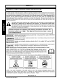 12
12
-
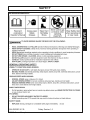 13
13
-
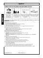 14
14
-
 15
15
-
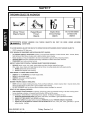 16
16
-
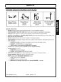 17
17
-
 18
18
-
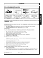 19
19
-
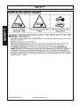 20
20
-
 21
21
-
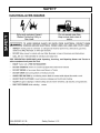 22
22
-
 23
23
-
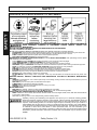 24
24
-
 25
25
-
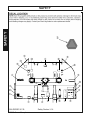 26
26
-
 27
27
-
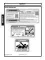 28
28
-
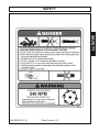 29
29
-
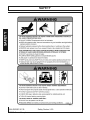 30
30
-
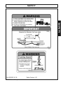 31
31
-
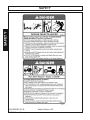 32
32
-
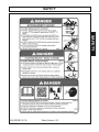 33
33
-
 34
34
-
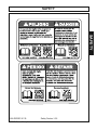 35
35
-
 36
36
-
 37
37
-
 38
38
-
 39
39
-
 40
40
-
 41
41
-
 42
42
-
 43
43
-
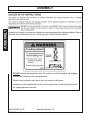 44
44
-
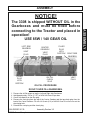 45
45
-
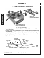 46
46
-
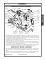 47
47
-
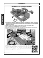 48
48
-
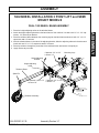 49
49
-
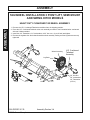 50
50
-
 51
51
-
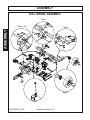 52
52
-
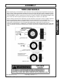 53
53
-
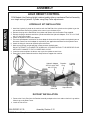 54
54
-
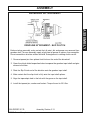 55
55
-
 56
56
-
 57
57
-
 58
58
-
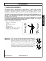 59
59
-
 60
60
-
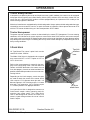 61
61
-
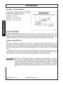 62
62
-
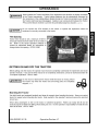 63
63
-
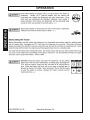 64
64
-
 65
65
-
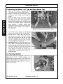 66
66
-
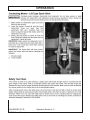 67
67
-
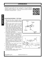 68
68
-
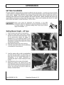 69
69
-
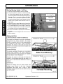 70
70
-
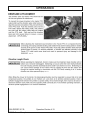 71
71
-
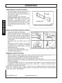 72
72
-
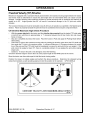 73
73
-
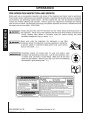 74
74
-
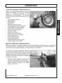 75
75
-
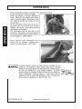 76
76
-
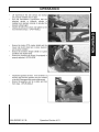 77
77
-
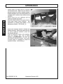 78
78
-
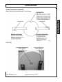 79
79
-
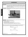 80
80
-
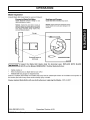 81
81
-
 82
82
-
 83
83
-
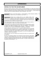 84
84
-
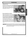 85
85
-
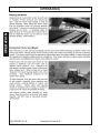 86
86
-
 87
87
-
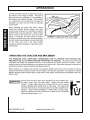 88
88
-
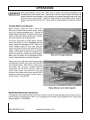 89
89
-
 90
90
-
 91
91
-
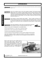 92
92
-
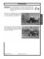 93
93
-
 94
94
-
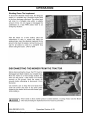 95
95
-
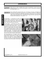 96
96
-
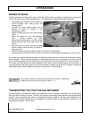 97
97
-
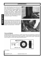 98
98
-
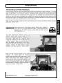 99
99
-
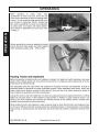 100
100
-
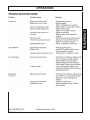 101
101
-
 102
102
-
 103
103
-
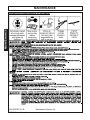 104
104
-
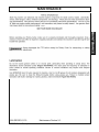 105
105
-
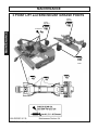 106
106
-
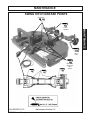 107
107
-
 108
108
-
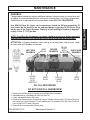 109
109
-
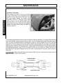 110
110
-
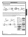 111
111
-
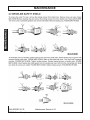 112
112
-
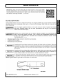 113
113
-
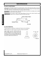 114
114
-
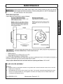 115
115
-
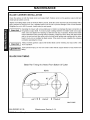 116
116
-
 117
117
-
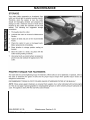 118
118
-
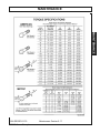 119
119
-
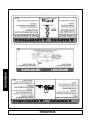 120
120
-
 121
121
-
 122
122
-
 123
123
-
 124
124
-
 125
125
-
 126
126
-
 127
127
-
 128
128
-
 129
129
-
 130
130
-
 131
131
-
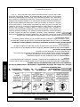 132
132
-
 133
133
-
 134
134
-
 135
135
-
 136
136
-
 137
137
-
 138
138
-
 139
139
-
 140
140
-
 141
141
-
 142
142
-
 143
143
-
 144
144
-
 145
145
-
 146
146
-
 147
147
-
 148
148
-
 149
149
-
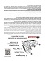 150
150
-
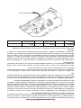 151
151
-
 152
152


Bush Hog Multi-Spindle Rotary Cutter El manual del propietario
- Categoría
- Cortadoras de césped
- Tipo
- El manual del propietario
en otros idiomas
Artículos relacionados
-
Bush Hog Multi-Spindle Rotary Cutter El manual del propietario
-
-
-
-
-
-
-
-
-