Commercial Electric EC4788BK-3-A Instrucciones de operación
- Tipo
- Instrucciones de operación

Item #1000038669
Model #EC4788BK-3-A
THANK YOU
USE AND CARE GUIDE
Questions, problems, missing parts? Before returning to the store call
8 a.m. - 6 p.m., EST, Monday - Friday
1-877-527-0313
HOMEDEPOT.COM
3 Light Linear Track Kit
2
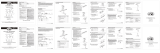
Table of Contents
IMPORTANT SAFETY INSTRUCTIONS
Safety Information
Read all instructions. Save these instructions and refer to them
made.
Do not install any part of this track system less than 7 ft.
above the oor.
Do not install any lamps closer than 6 in. from any curtain
or similar combustible material.
This track system is not intended for use with a power supply
cord or convenience receptacle adaptor.
This track system must be supplied by a single branch
120 volt circuit.
The track is not intended to be pendant mounted such as by a
stem or cable.
The mounting screws are to be mounted along the track in the
keyhole slots provided.
Disconnect electrical power before adding to or changing the
□
□
□
□
□
□
□
□
□
□
□
Table of Contents
......................................
2
Safety Information
....................................
2
Warranty
...................................................
...................................................
3
3
3
.....................................
.....................................
....................................
3
Hardware Included
.....................................
4
Package Contents
Pre-Installation
.........................................
Installation
Operation
gninaelC dna eraC
........................................
8
8
8
5
Troubleshooting
........................................
SAVE THESE INSTRUCTIONS
Before energizing, make sure that the lighting system is clear
of all material which could cause a direct short, and check all
electrical connections to make sure they are secure.
Do not attempt to energize anything other than EC series track
tools, extension cords, appliances, etc. to the track.
Lamp gets hot quickly! Touch only the switch or plug when
turning on. Do not touch the hot lamp lens. Turn off power and
allow bulbs to cool down before replacing.
WHEN INSTALLING OR USING THIS TRACK SYSTEM, BASIC SAFETY PRECAUTIONS SHOULD ALWAYS BE FOLLOWED INCLUDING THE
FOLLOWING:
WARNING: Do not install this lighting system in a damp or
wet location.
IMPORTANT: For use with Commercial Electric and
Hampton Bay EC series line voltage track systems only.
CAUTION: Lighted lamp is hot!
CAUTION: To reduce the risk of a burn during re-lamping,
remove from the track before re-lamping.
CAUTION: Hot surface, keep away from curtains or
any other combustible material.
NOTE: All electrical connections must be in accordance with
local codes and the National Electrical Code. If you are
unfamiliar with methods of installing electrical wiring, secure
CAUTION: Refer to the re-lamping label located on the
3
Warranty
PLANNING INSTALLATION
TOOLS REQUIRED
Ladder Safety
goggles
Wire
stripper
Gloves
Phillips
screwdriver
Electrical
tape
Drill 7/32 in. or 5/8 in. Drill bits
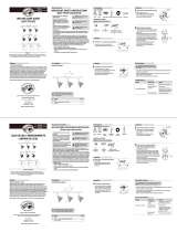
HARDWARE INCLUDED
AA
B
B
CC
DD
EE
Pre-installation
Part
Description
Quantity
2
2
2
DD
CC
BB
AA
EE
Wire connector
Machine screw
Anchor
Phillips screw
Toggle bolts
3
2
Contact the Customer Service Team at 1-877-527-0313 or visit www.homedepot.com.
Read all instructions before assembly.
To avoid damaging this product, assemble it on a soft, non-abrasive surface such as carpet or cardboard. Inspect each part for
damage that may have occurred during shipping.
Keep your receipt and these instructions for proof of purchase.
Hacksaw
NOTE: Hardware not shown to actual size.
HOMEDEPOT.COM
Please contact 1-877-527-0313 for further assistance.
4
Pre-installation (continued)
PACKAGE CONTENTS
Description
Quantity
A
2
B
1
C
1
D
1
E
2
F
1
G
3
3
3
6
H
Bulb
I
J
Part
Track mounting screw [preassembled to mounting plate (B)]
Mounting plate
Twist-lock connector [preassembled to mounting plate (B)]
Canopy [preassembled to mounting plate (B)]
Canopy screw [preassembled to canopy (D)]
Track section
Track head
Connector’s locking tab [preassembled to track head (G)]
Knob [preassembled to track head (G)]
7
7
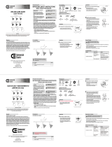
Installation (continued)
Connecting the canopy to the track
Installing the bulb
8
□
□
□
□
Twist the twist-lock connector (C) into the track section (F).
Secure the canopy (D) to the mounting plate (B) by tightening
the previously removed canopy screws (E).
When the twist-lock connector (C) is twisted into position on
the track section (F), make sure the two copper tabs on the
side of the twist-lock connector (C) align with the two copper
strips inside the track section (F). This is necessary to
maintain polarity.
HOMEDEPOT.COM
Please contact 1-877-527-0313 for further assistance.
8
Installing the track head to the track
Removing the track head from the track
9
Operation
Care and Cleaning
CAUTION:
Problem
Possible
C
ause
Solution
Make sure the power supply is on.
There is a faulty wire connection.
There is a faulty switch.
There are crossed wires, or the power
wire is not properly grounded.
NOTE: The ground side of the track head (G) connector is the side with two
metal tabs. The ground side of the track section (F) has an indented groove
on the face and two internal copper strips. The track head (G) can only be
assembled if the ground sides of the track head (G) connector and the track
section (F) are aligned.
The light bulb will
not illuminate.
Check the wire connections.
□
□
□
□
□
□
□
□ □
□
□
□
□
□
□
□
Identify the ground side on the track head (G) connector and track
section (F).
Push the top portion of the track head (G) connector into the slot of the
track section (F).
Pull down the connector’s locking tab (I). Twist the ground side of the track
head (G) connector toward the ground side of the track section (F) until the
track head (G) connector snaps into place.
Use a dry or slightly dampened, clean cloth (use clean water, never use a solvent) to wipe the interior and exterior surfaces of the
Troubleshooting
The light bulb is burned out.
The power is off.
Replace the light bulb.
Check the wiring.
you are not comfortable troubleshooting
wiring problems.
Test or replace the switch.
track head (G) to cool down.
Pull down on the track head connector’s locking tab (I), and twist until
the track head (G) disengages.
□
Questions, problems, missing parts? Before returning to the store,
call Commercial Electric Customer Service
8 a.m. - 6 p.m., EST, Monday-Friday
1-877-527-0313
HOMEDEPOT.COM
Retain this manual for future use.
GUÍA DE USO Y MANTENIMIENTO
¿Preguntas, problemas o piezas faltantes? Antes de regresar a la tienda,
llama al Servicio al Cliente de Commercial Electric, de
8 a.m. a 6 p.m., hora estándar del Este, de Lunes a Viernes
1-877-527-0313
HOMEDEPOT.COM
Kit de Riel Lineal de 3 Luces
GRACIAS POR TU COMPRA
2
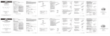
Índice
INSTRUCCIONES IMPORTANTES DE SEGURIDAD
Información de Seguridad
Lee todas las instrucciones. Guarda estas instrucciones y
consúltalas cuando hagas cambios o cuando amplíes la
No instales partes de este riel sistema a menos de 7 pies
(2,2 m) sobre el piso.
No instales lámparas a menos de 6 pulgadas (15,25cm) de
distancia de cortinas o material combustible similar.
Este sistema de riel no está diseñado para funcionar con un
cable de alimentación o un adaptador de receptáculo común.
Este sistema de riel debe recibir energía de un solo circuito
derivado de 120 voltios.
Este riel no debe colgarse de un tubo o un cable.
Los tornillos de montaje deben montarse a lo largo del riel en
las ranuras tipo ojo de cerradura incluidas.
□
□
□
□
□
□
□
□
□
□
□
Índice
..................................................
2
Información de Seguridad
....................................
2
Garantía
...................................................
...................................................
3
3
3
............................................
.......................................
..................................................
sairaseceN satneimarreH
3
Herrajes Incluidos
.....................................
4
Contenido del paquete
Pre-Instalación
.............................................
Instalación
Funcionamiento
azeipmiL y otneiminetnaM
...................................
8
8
8
5
samelborP ed nóiculoS
........................................
GUARDA ESTAS INSTRUCCIONES
Antes de dar energía, asegúrate de que no haya ningún
material en el sistema de iluminación que pueda causar un
eléctricas estén seguras.
¡La lámpara se calienta rápidamente! Sólo toca el interruptor o
enchufe para encender. No toques los cristales de la lámpara
cuando estén calientes. Apague la lámpara y permita que se
enfríe la bombilla antes de reemplazarla.
DURANTE LA INSTALACIÓN O USO DE ESTE SISTEMA DE RIELES, SE DEBEN TOMAR PRECAUCIONES BÁSICAS DE SEGURIDAD INCLUIDAS
LAS SIGUIENTES:
Desconecta la electricidad antes de agrandar el riel o
Sólo debes conectar a la electricidad los componentes en el
riel o luces de rieles de la serie EC. Para evitar riesgo de
incendios y descargas eléctricas, no intentes conectar
herramientas eléctricas, cables de extensión,
electrodomésticos, etc. al sistema de riel.
ADVERTENCIA: No instales este sistema de iluminación
IMPORTANTE: Para uso con sistemas de riel de tensión
¡La lámpara se calienta!
Para disminuir el riesgo de quemaduras
PRECAUCIÓN:
PRECAUCIÓN:
PRECAUCIÓN:
NOTA: Todas las conexiones se deben hacer conforme con el
No toques la bombilla en ningún momento.
PRECAUCIÓN:
en un lugar húmedo.
de línea de la serie Commercial Electric y Hampton Bay EC
solamente.
durante el cambio de las bombillas, desmonta la lámpara del
riel antes de cambiar la bombilla.
las cortinas y otros materiales combustibles.
Usa un paño suave, la grasa de la piel puede dañar la lámpara.
Consulta la etiqueta para cambio de
PRECAUCIÓN:
Código Nacional de Electricidad y con los códigos de
electricidad locales. Si no estás familiarizado con los métodos
de instalación del cableado eléctrico, contrata los servicios de
bombilla que viene con la lámpara. No excedas el vataje
recomendado.
3
Garantía
PLANIFICAR LA INSTALACIÓN
HERRAMIENTAS NECESARIAS
Escalera
Gafas de
seguridad
Pelacables
Guantes
Destornillador
Phillips
Cinta aislante
Taladro Brocas de taladro de
7/32 plg o de 5/8 plg
HERRAJES INCLUIDOS
AA
B
B
CC
DD
EE
Pre-Instalación
Pieza
Descripción
Cantidad
2
2
Tornillo Phillips
2
Ancla de expansión
DD
EE
CC
BB
AA
Conector de cables
3
2selatem arap ollinroT
Comunícate con el Equipo de Servicio al Cliente al 1-877-527-0313 o visita www.homedepot.com.
Lee todas las instrucciones antes de ensamblar.
que ninguna de las partes haya sufrido daños durante el envío.
Conserva el recibo y estas instrucciones como comprobante de compra.
Sierra para
metales
NOTA: No se muestra el tamaño real de los herrajes.
HOMEDEPOT.COM
Para obtener asistencia, llama al 1-877-527-0313.
4
Pre-Instalación (continuación)
CONTENIDO DEL PAQUETE
Descripción
Cantidad
A
2
B
1
C
1
D
1
E
2
F
1
G
3
3
3
6
H
Bombilla
I
J
Pieza
Tornillos de montaje del carril [preensamblado de placa de montaje (B)]
Placa de montaje
Suministro de Electricidad [preensamblado de placa de montaje (B)]
Cubierta [preensamblado de placa de montaje (B)]
Tornillos de la Cubierta [preensamblado de la cubierta (D)]
Sección del carril
Cabezal del carril
Lengüeta de seguridad del conector [preensamblado en el cabezal del carril (G)]
Perilla [preensamblado en el cabezal del carril (G)]
7
7
Instalación (continuación)
Conectar la cubierta al riel
Instalar la bombilla
8
□
□
□
□
Gire el suministro de electricidad (C) en la sección del carril (F).
Asegure la cubierta (D) a la placa de montaje (B) apretando
los tornillos de la cubierta (E).
Cuando el suministro de electricidad (C) se giraen su
posición en la sección del carril lineal (F), asegúrese de
que las dos lengüetas de cobre delcostado del suministro
de electricidad (C) se alineencon las dos tiras de cobre en
el interior de la seccióndel carril lineal (F). Esto es necesario
para mantenerla polaridad.
HOMEDEPOT.COM
Para obtener asistencia, llama al 1-877-527-0313.
8
Instalar el jefe de riel hasta el riel
Desmontar el cabezal del riel
9
Funcionamiento
Mantenimiento y Limpieza
Problema
Causa Posible
Solución
Compruebe si hay suministro de electricidad.
Hay una conexión defectuosa del cable.
Hay un interruptor defectuoso.
Hay cables cruzados o el cable de
alimentación no está haciendo tierra.
NOTA: El lado de puesta a tierra del conector del cabezal del carril (G) es el lado
con las dos lengüetas de metal. El lado de puesta a tierra de la sección del carril
(F) tiene una ranura dentada en la parte frontal y dos tiras de cobre internas. El
cabezal del carril (G) sólo se puede ensamblar si los lados con puesta a tierra del
cabezal del carril (G) y la sección del carril (F) están alineados.
La bombilla no enciende.
Revisa las conexiones de cable.
□
□
□
□
□
□
□
□ □
□
□
□
□
□
□
□
del carril (G) y la sección del carril (F).
Presione la parte superior del conector del cabezal del carril (G)
en la ranura de la sección del carril (F).
Baje la lengüeta de bloqueo del conector (I). Gire el lado de puesta
a tierra del conector del cabezal del carril (G) hacia el lado de puesta
a tierra de la sección del carril (F) hasta que el conector del cabezal
Ficha tierra
Tierra del surco
Lado de puesta a
tierra en el conector
Usa un paño limpio, seco o ligeramente húmedo (usa sólo agua limpia, nunca un solvente) para limpiar el interior y exterior de la
lámpara.
Solución de problemas
El fusible se funde o el
cortacircuitos se activa en el
momento en que enciendes la luz.
La bombilla está quemada.
No hay alimentación.
Reemplace la bombilla.
Revisa el cableado.
solución de problemas del cableado.
Prueba o reemplaza el interruptor.
Jale hacia abajo la lengüeta de bloqueo del conector (I) del cabezal
del carril y gire hasta que el cabezal del carril (G) se libere.
□
Para retirar el cabezal del carril (G) de la sección del carril (F),
primero permita que se enfríe el cabezal del carril (G).
Para limpiar la lámpara, desconecta primero la electricidad apagando el cortacircuitos o quitando el fusible correspondiente en la
caja de fusibles.
Deja secar la lámpara completamente antes de restablecer la electricidad.
PRECAUCIÓN:
No uses solventes químicos o abrasivos fuertes para limpiar la lámpara o los componentes, porque se
pueden dañar.
¿Preguntas, problemas o piezas faltantes? Antes de regresar a la tienda,
llama al Servicio al Cliente de Commercial Electric, de
8 a.m. a 6 p.m., hora estándar del Este, de Lunes a Viernes
1-877-527-0313
MOC.TOPEDEMOH
Conserva este manual para uso en el futuro.
We appreciate the trust and condence you have placed in Commercial Electric throght the purchase of this linear track kit.
We strive to
continually create quality products designed to enhance your home. Visit us online to see our full line of products available for your
home improvement needs. Thank you for choosing C
ommercial Electric!
Apreciamos la conanza que has depositado en Commercial Electric al comprar esta kit de riel lineal. Nos esforzamos para continuamente
crear productos de calidad diseñados para mejorar tu hogar. Visítanos por Internet para ver nuestra línea completa de productos
disponibles para las necesidades de mejoras de tu hogar. ¡Gracias por elegir Commercial Electric!
F
G
H
J
I
B
A
C
D
E
C
F
B
D
E
C
F
B
D
E
Artículo #1000038669
Modelo #EC4788BK-3-A
H
G
Insert the bulb (H) into the track head (G).
Inserte la bombilla (H) en el cabezal del carril (G).
Ground tab
Ground groove
Ground side of connector
G
F
I
5
HOMEDEPOT.COM
Please contact 1-877-527-0313 for further assistance.
6
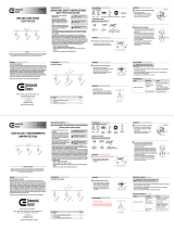
Installation (continued)
Installing the mounting bracket
4
EE B
Secure the mounting plate (B) to the outlet box with machine
screws (EE).
Installing the track to the ceiling
5
F
AA
Place the linear track section (F) in the desired location on the mounting plate (B) between the two track mounting screws (A).
Mark the location of the track section (F) on the ceiling with a pencil (not included) through the mounting holes in the bottom of the
track section (F).
Attach the track section (F) to the desired location on the ceiling in one of the following ways:
Drill a 5/8 in. hole at each mark on the ceiling.
Insert toggle bolts (AA) through the track section (F), and
thread 1/2 in. toggle onto bolts.
Place the track section (F) against the ceiling, and insert the
toggle bolts (AA) into the holes until the springs open.
Tighten the bolts (AA).
5a
NOTE: Toggle bolts (AA) should be used for standard installation into drywall, drop ceiling, or suspended ceiling
applications. Anchors (CC) are used for masonry installations ONLY.
Toggle bolt installation
□
□
□
□
□
□
□
□
□
Align the holes in the mounting plate (B) with the holes in the
outlet box.
B
F
A
5b
Anchor installation
6
BB
F
CC
Drill a 7/32 in. hole at each mark on the ceiling, and insert
the anchors (CC) into the mounting surface.
Insert the Phillips screws (BB) through the track section (F),
and tighten to the anchors (CC).
Attaching the mounting plate to the track
□
□
□
Tighten the track mounting screws (A) to secure the track
section (F) to the mounting plate (B).
5
Instalación
HOMEDEPOT.COM
Para obtener asistencia, llama al 1-877-527-0313.
6
Instalación (continuación)
3
DD
Caja desalida
Instalar el soporte de montaje
4
Fije la placa de montaje (B) a la caja de salida con los tornillos
para metales (EE).
Instalar el riel hasta el techo
5
F
AA
Coloque la sección del carril lineal (F) en la ubicación deseada en la placa de montaje entre los dos tornillos de montaje del .)A( lirrac
arte
inferior de la sección del carril (F).
Fije la sección del carril (F) en la ubicación deseada en el techo en una de las siguientes maneras:
enrosque tapas de ½ pulg. sobre los tornillos.
Coloque la sección del carril (F) contra al techo e inserte los
luego apriete los tornillos (AA).
5a
Conectar los cables
NOTA:
del techo. Las anclas de expansión (CC) se usan SÓLOpara instalaciones en mampostería.
Instalar el perno acodado
□
□
□
□
□
□
□
□
□
□
□
□
Conecte los cables (los cables blancos del conector a los cables
blancos del circuito de suministro, los cables negros del conector
a los cables negros del circuito de suministro y los cables de
verde del conector a los cables de verde del circuito de
suministro) con los conectores de cables (DD).
Cubra con cinta aislante (no se incluye) los conectores de cables
(DD) y asegúrese de que estén seguros.
Introduzca el exceso de cables y los conectores de cables (DD)
en la caja de salida (no se incluye).
la caja de salida.
B
F
A
5b
Instalación de los anclajes
6
BB
F
CC
Inserte los tornillos Phillips (BB) a través de la sección del
carril (F) y apriete las anclas de expansión (CC).
Fijar la placa de montaje al riel
□
□
□
Apriete los tornillos de montaje (A) del carril para asegurar
la sección del carril lineal (F) a la placa de montaje (B).
1
B
2
la placa de montaje (B).
No retire los tornillos (A) completamente.
Riel de corte de área para longitudes especiales (Opcional):
Separar la cubierta
F
NOTA: El corte se debe realizar preferiblemente desde el extremo cerrado del riel.
□
□
□
Retire los tornillos de la cubierta (E) del cubierta (D) para
exponer la placa de montaje (B).
B
A
C
D
E
montaje.
EE B
H
G
G
F
I
G
F
I
G
F
I
J
□
2
1
G
J
Adjusting the knob
□
2
1
G
F
G
H
J
I
B
A
C
D
E
Loosen the knob (J) on the side of the track head (G)
to adjust the light to your desired direction. Tighten
the knob (J) when nished.
Commercial Electric Customer Service
Tools Required
CAUTION: Do not touch the lamp at any time. Use a soft
cloth. Oil from skin may damage the lamp.
The fuse blows or circuit breaker
trips when the light bulb is
illuminated.
Cómo ajustar la perilla
Aoja la perilla (J) en el lado del cabezal del riel (G)
para ajustar la dirección de la luz. Aprieta la perilla (J)
cuando alcances la dirección deseada de iluminación.
The manufacturer warrants this lighting xture against defects in materials and workmanship for a period of one year from the date of
purchase. If within this period the product is found to be defective in material or workmanship, the product must be returned, with a
copy of the bill of sale as proof of purchase, to the original place of purchase. The manufacturer will, at its option, repair, replace, or
refund the purchase price to the original purchaser or consumer. This warranty does not cover light bulbs or the xture becoming
damaged due to misuse, accidental damage, improper handling and/or installation, and specically excludes liability for direct,
incidental, or consequential damages. As some states do not allow exclusions or limitations on an implied warranty, so the above
exclusions and limitations may not apply. This warranty gives you specic rights and you may also have other rights that vary from
state to state.
El fabricante garantiza que esta lámpara estará libre de defectos en materiales y mano de obra por un periodo de cincoaño a partir de
la fecha de su compra. Si durante este lapso, el producto resulta defectuoso en cuanto a material omano de obra, deberá devolverlo al
lugar de la compra original, junto con una copia de la factura de venta comocomprobante de la compra. El fabricante, según su criterio,
reparará, sustituirá o reembolsará el precio de la compra alcomprador o consumidor original. Esta garantía no cubre los focos ni que la
luminaria resulte dañado debido a un maluso, daño accidental, manejo o instalación inapropiados y, asimismo, de manera especica
excluye la responsabilidad por daños directos, incidentales o emergentes. Puesto que algunos estados no permiten las exclusiones o
limitacionesen una garantía implícita, es posible que las exclusiones y limitaciones anteriores no se apliquen. Esta garantía le brinda
derechos legales especicos y usted podría tener también otros derechos que varían según el estado.
Installation
1
2
Loosen the track mounting screws (A) preassembled to the
mounting plate (B).
Do not remove the track mounting screws (A) completely.
Field cuttin
g the track to special
lengths (Optional)
Separating the canopy
NOTE: Cutting should be done preferably from the dead end of the track.
□
□
□
Remove the canopy screws (E) from the canopy (D) to
expose the mounting plate (B).
3
DD
Outlet Box
Connecting the wires
□
□
□
Connect the wires (white wires from connector to the white
wires from the supply circuit, black wires from the connector
to the black wires from the supply circuit, and the green
ground wire from the connector to the ground wire of the
supply circuit) using the wire connectors (DD).
Wrap electircal tape (not included) around wire connectors
(DD) and make sure they are secure.
Push all excess wire and wire connectors (DD) back into the
outlet box (not included).
B
A
C
D
E
B
F
□
4 ft. or less in length has one mounting opening spaced a maximum of 6 in.
from each track end section. A single section of track that is greater than 4 ft.
in length must have mounting openings a maximum of 12 in. from each end of the
track with additional openings a minimum of every 4 ft. along the length of the
track section. Additional openings every 4 ft. along the track section may
be added as needed.
□
□
□
□
□
□
□
□
Slide the copper bus bars and insulators ush or even with the end of the track (F).
With a ne tooth hacksaw, cut off the desired length of track (cut straight
down through the track).
Remove all burrs from the track, insulators, and copper bus bars so the end
is smooth to the touch.
Slide the copper bus bars and insulators back into the track leaving approx. ¼ in
space between the end of the track and the insulator, copper bus bar assembly.
Reinstall the dead end tting and secure with the Philips head tension screw.
Make appropriate, slight modications necessary to securely reinstall the dead
end tting back into the track (F).
Align the track so the open side is facing upward (the side where
the copper bus bars are exposed).
Using a Philips head screwdriver, loosen the tension screw and
remove the dead end tting from the end of the track (F).
□
Después de que el riel haya sido cortado, asegúrate de que cada segmento
de 4 pies (1,22 m) o menos tenga una abertura para el montaje a una
distancia máxima de 6 plg (150mm) del extremo cada sección de riel. Sólo
una de las secciones del riel que mida más de 4 pies (1,22 m) de largo debe
tener una abertura de 12 plg (300 mm) para el montaje, como máximo, desde
cada extremo del riel con aberturas adicionales cada 4 pies (1,22 m) a lo largo
de todo el riel. Las aberturas adicionales cada 4 pies (1,22 m) a lo largo de la
sección del riel se deben agregar según sea necesario.
□
□
□
□
□
□
□
□
Desliza las barras de distribución de cobre y los aislantes para que queden
al ras o nivelados con el extremo del riel (F).
Con una sierra para metales de dientes nos, corta el largo deseado del
riel (corta de manera recta por el riel).
Quita todas las asperezas del riel, los aislantes y las barras de distribución
de cobre de modo que el extremo del riel quede suave al tacto.
Desliza las barras de distribución de cobre y los aislantes nuevamente hacia
el riel, dejando aproximadamente 6.4 mm entre el extremo del riel y el aislante
en el ensamblaje de la barra de distribución de cobre.
Vuelve a instalar la pieza del extremo y asegura con el tornillo tensor Philips.
Realiza las modicaciones necesarias para volver a instalar de manera segura
la pieza del extremo en el riel (F).
Alinea el riel de modo que el lado abierto quede hacia arriba (el lado donde las
barras de distribución de cobre quedan expuestas).
Con un destornillador Phillips, aoja el tornillo tensor y quita la pieza del
acoplamiento del extremo del riel (F).
-
 1
1

Commercial Electric EC4788BK-3-A Instrucciones de operación
- Tipo
- Instrucciones de operación
en otros idiomas
Otros documentos
-
 Regal King EC1577WH Guía de instalación
-
 World Imports WI801908 Guía del usuario
-
 Hampton Bay EC1588WH Guía de instalación
-
 Hampton Bay 804839 Guía de instalación
-
 Hampton Bay 813850 Guía de instalación
-
 Hampton Bay DC6833SBA Instrucciones de operación
-
 Hampton Bay DC5939ABZ Guía del usuario
-
 Hampton Bay DC6833SBA Guía del usuario


