Kichler Lighting 44336DBK Manual de usuario
- Tipo
- Manual de usuario

IS-44336-US
We’re here to help 866-558-5706
Hrs: M-F 9am to 5pm EST
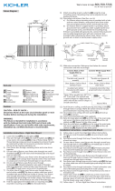
4) Make wire connecon. Reference chart below for correct
connecons and wire accordingly.
Connect Black or Red
Supply Wire to:
Connect White Supply
Wire to:
Black White
*Parallel cord (round &
smooth)
*Parallel cord (square &
ridged)
Clear, Brown, Gold or
Black without Tracer
Clear, Brown, Gold or Black
with Tracer
Insulated wire (other
than green) with copper
conductor
Insulated wire (other
than green) with silver
conductor
*Note: When parallel wire (SPT
1 & SPT 2) are used. The neutral
wire is square shaped or ridged
and the other wire will be round
in shape or smooth (see illus.)
Neutral Wire
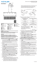
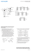
5) Aach the inspecon cable[L] to the mounng strap
or to the inside of the mounng box. Push xture to
ceiling, carefully passing mounng screws through holes
in canopy[E]. NOTE: Be certain wires do not get pinched
between canopy and ceiling.
6) Use knobs[J] and lockwashers[K] to secure canopy.
Tighten to secure.
7) Raise the side glass panel[I] up to the side of the main
body and secure into place using four (4) screws[G] and
four (4) sloed nuts[H]. Repeat for the other panels.
8) Insert recommended bulbs(s) (Not supplied).
9) Raise the boom glass panel[F] up to the boom of the
main body and secure into place using four(4) screws[G]
and four(4) sloed nuts[H].
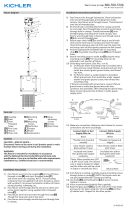
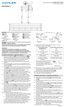
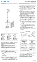
Fixture Diagram
Parts List
Cauons
CAUTION – RISK OF SHOCK –
Disconnect Power at the main circuit breaker panel or main
fusebox before starng and during the installaon.
WARNING:
This xture is intended for installaon in accordance
with the Naonal Electrical Code (NEC) and all local code
specicaons. If you are not familiar with code requirements,
installaon by a cered electrician is recommended.
Installaon Instrucons
[A] Mounting
Stap
[B] Mounting
Screws
[C] Outlet Box
[D] Strap
Mounting
Screws
[E] Canopy
[F] Bottom Glass
Panel
[G] Screws
[H] Slotted Nuts
[I] Side Glass
Panels
[J] Knobs
[K] Lockwashers
[L] Inspection
Cable
1) Find the appropriate threaded holes on mounng
strap[A]. Assemble mounng screws[B] into threaded
holes.
2) Aach mounng strap to outlet box[C] using the
strap mounng screws[D]. The mounng strap can be
adjusted to suit posion of xture.
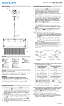
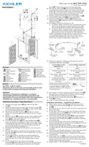
3) Grounding instrucons: (See Illus. a or b).
a) On xtures where mounng strap is provided with a
hole and two raised dimples, wrap ground wire from
outlet box around green ground screw, and thread
into hole.
b) On xtures where a cupped washer is provided,
aach ground wire from outlet box under cupped
washer and green ground screw, then thread into
mounng strap.
If xture is provided with ground wire, connect xture
ground wire to outlet box ground wire with wire
connector aer following the above steps. Never connect
ground wire to black or white power supply wires.
GREEN GROUND
SCREW
CUPPED
WASHER
OUTLET BOX
GROUND
FIXTURE
GROUND
DIMPLES
WIRE CONNECTOR
OUTLET BOX
GROUND
GREEN GROUND
SCREW
FIXTURE
GROUND
a
b
C
A
D
B
E
J
K
G
F
H
I
L
Installaon Instrucons (connued)

IS-44336-US
Estamos aquí para ayudarle 866-558-5706
Horario: Lunes-Viernes 9am a 5pm EST (hora ocial del este)
4) Haga les conexiones de los alambres. La tabla de referencia
de abajo indica las conexiones correctas y los alambres
correspondientes.
Conectar el alambre de
suministro negro o rojo al
Conectar el alambre de
suministro blanco al
Negro Blanco
*Cordon paralelo (redondo
y liso)
*Cordon paralelo (cuadrado
y estriado)
Claro, marrón, amarillio
o negro sin hebra
idencadora
Claro, marrón, amarillio
o negro con hebra
idencadora
Alambre aislado (diferente
del verde) con conductor
de cobre
Alambre aislado (diferente
del verde) con conductor
de plata
*Nota: Cuando se uliza alambre
paralelo (SPT 1 y SPT 2). El alambre
neutro es de forma cuadrada o
estriada y el otro alambre será
de forma redonda o lisa. (Vea la
ilustracíón).
Hilo Neutral
5) Conecte el cable de inspección[L] a la placa de montaje o
al interior de la caja de montaje. Empuje la jación al techo,
pasando cuidadosamente los tornillos de montaje a través
de los oricios de la cubierta[E]. NOTA: Asegúrese de que los
cables no queden atrapados entre el cubierta y el techo.
6) Ulice las perillas[J] y las arandelas de seguridad[K] para
asegurar el cubierta. Apriete para asegurar.
7) Levante el panel lateral de vidrio[I] hasta el lado del cuerpo
principal y asegúrelo en su lugar ulizando cuatro (4)
tornillos[G] y cuatro (4) tuercas ranuradas[H]. Repita para los
otros paneles.
8) Inserte las bombillas recomendadas (no incluidas).
9) Levante el panel inferior de vidrio[F] hasta el parte inferior del
cuerpo principal y asegúrelo en su lugar ulizando cuatro (4)
tornillos[G] y cuatro (4) tuercas ranuradas[H].
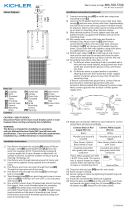
Diagrama de Accesorios
Lista de Partes
[A] La Correa de
Montaje
[B] Los tornillos
de Montaje
[C] Caja de Salida
[D] Tornillos de
Montaje de la
Correa
[E] Cubierta
[F] Panel Inferior
de Vidrio
[G] Tornillos
[H] Tuercas
Ranuradas
[I] Paneles
Laterales de
Vidrio
[J] Perillas
[K] Arandelas de
Seguridad
[L] Cable de
Inspección
Precauciones
PRECAUCIÓN – RIESGO DE DESCARGA ELÉCTRICA –
Desconecte la electricidad en el panel principal del
interruptor automáco o caja principal de fusibles antes de
comenzar y durante la instalación.
ADVERTENCIA:
Este accesorio está desnado a la instalación de
acuerdo con el Naonal Electrical Code (NEC) y todas las
especicaciones del código local. Si no está familiarizado
con los requisitos del código, la instalación se recomienda
un electricista cercado.
Instrucciones de Instalación
1) Encuentre los oricios roscados adecuados en la correa de
montaje[A]. Montar los tornillos de montaje[B] en los oricios
roscados.
2) Fije la correa de montaje a la caja de salida[C] con los tornillos
de montaje de la correa[D]. La correa de montaje se puede
ajustar para adaptarse a la posición del aparato.
3) Instrucciones de conexión a erra solamente para los Estados
Unidos. (Vea la ilustracion a o b).
a) En las lámparas que enen el eje, de montaje con un
agujero y dos hoyuelos realzados, enrollar el alambre a
erra de la caja tomacorriente alrededor del tornillo verde
y pasarlo por el aquiero.
b) En las lámparas con una arandela acopada, jar el alambre
a erra de la caja tomacorriente del ajo de la arandela
acoada y tornillo verde, y paser por el eje de montaje.
Si la lámpara viene con alambre a erra, conecter el alambre a
erra de la lámpara al alambre a erra de la caja tomacorriente
con un conector de alambres espués de seguir los pasos
anteriores. Nunca conectar el alambra a erra a los alambres
eléctros negro o blanco.
ARANDELA
CONCAVA
TIERRA DE LA
CAJA DE SALIDA
TORNILLO DE TIERRA,
VERDE
DEPRESIONES
TIERRA
ARTEFACTO
CONECTOR DE ALAMBRE
TIERRA DE LA
CAJA DE SALIDA
TORNILLO DE TIERRA,
VERDE
TIERRA
ARTEFACTO
a
b
C
A
D
B
E
J
K
G
F
H
I
L
Instrucciones de Instalación
-
 1
1
-
 2
2


Kichler Lighting 44336DBK Manual de usuario
- Tipo
- Manual de usuario
en otros idiomas
Artículos relacionados
-
 Kichler Lighting 44335DBK Manual de usuario
-
 Kichler Lighting 44332DBK Manual de usuario
-
 Kichler Lighting 44333DBK Manual de usuario
-
 Kichler Lighting 44334DBK Manual de usuario
-
 Kichler Lighting 44168BK Manual de usuario
-
 Kichler Lighting 44337DBK Manual de usuario
-
 Kichler Lighting 43980BK Manual de usuario
-
 Kichler Lighting 45905CH Manual de usuario
-
 Kichler Lighting 44250NI Manual de usuario
-
 Kichler Lighting 43979BK Manual de usuario


