
CONVERTING TO PROPANE
GAS (OR CONVERTING
BACK TO NATURAL GAS
FROM PROPANE)
This range leaves the factory set for use with
natural gas. If you want to convert to propane
gas, the conversion must be performed by a
qualified propane gas installer.
The conversion orifices and instructions can
be found on back of the range.
Keep these instructions and all orifices in case
you want to convert back to natural gas.
DIMENSIONS AND
CLEARANCES
Provide adequate clearances between the
range and adjacent combustible surfaces.
These dimensions must be met for safe use of
your range.
Allow 30” (76.2 cm) minimum clearance
between burners and bottom of unprotected
wood or metal cabinet, or allow a 24” (61 cm)
minimum when bottom of wood or metal cabinet
is protected by no less than 1/4” (6.4 mm) thick
flame-retardant millboard covered with no less
than No. 28 MSG sheet metal (.015” [.38 mm]
thick), .015” (.38 mm) thick stainless steel, .025”
(0.64 mm) aluminum or .020” (0.5 mm) copper.
Installation of a listed microwave oven or
cooking appliance over the cooktop shall
conform to the installation instructions packed
with that appliance.
For island installation, maintain 2-1/2” minimum
from cutout to back edge of countertop and
3” minimum from cutout to side edges of
countertop.
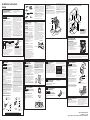
CONNECTOR HOOKUP
TOOLS YOU WILL NEED MATERIALS YOU MAY NEED
ŶGas line shut-off valve
ŶPipe joint sealant or UL-approved pipe thread
tape with Teflon* that resists action of natural
and propane gases
ŶFlexible metal appliance connector (1/2” I.D.).
A 5-foot length is recommended for ease of
installation but other lengths are acceptable.
Never use an old connector when installing a
new range.
ŶFlare union adapter for connection to gas
supply line (3/4” or 1/2” NPT x 1/2” I.D.)
ŶFlare union adapter for connection to pressure
regulator on range (1/2” NPT x 1/2” I.D.)
ŶLiquid leak detector or soapy water.
*Teflon: Registered trademark of DuPont
Flat-blade
screwdriver
Pipe wrenches (2)
(one for backup)
Phillips
screwdriver
Open-end or
adjustable wrench
Pencil and ruler
Level
Drill, awl or nail
Pressure
regulator
Gas Flow into Range Gas Flow into Range
Flex
connector
(6 ft. max.)
Adapter
Installer: Inform the consumer of the location of the gas shut-off valve.
1/2” or 3/4”
Gas pipe
Adapter
Gas
shut-off
valve
Pressure
regulator
Elbow
Elbow
Nipple
Union
Nipple
Gas
shut-off
valve
1/2” or 3/4”
Gas pipe
Flexible
Option
Rigid Pipe
Option
IN THE COMMONWEALTH
OF MASSACHUSETTS
ŶThis product must be installed by a licensed
plumber or gas fitter.
ŶWhen using ball type gas shut-off valves,
they shall be the T-handle type.
ŶA flexible gas connector, when used, must
not exceed 5 feet.
BEFORE YOU BEGIN
IMPORTANT — Save these
instructions for local inspector’s use.
IMPORTANT — Observe all governing
codes and ordinances.
IMPORTANT — Remove all packing
material and literature from oven before
connecting gas and electrical supply to range.
IMPORTANT — To avoid damage
to your cabinets, check with your builder
or cabinet supplier to make sure that the
materials used will not discolor, delaminate
or sustain other damage. This oven has been
designed in accordance with the requirements
of UL and CSA International and complies
with the maximum allowable wood cabinet
temperatures of 194°F (90°C).
Note to Installer – Be sure to leave these
instructions with consumer.
Note to consumer – Keep these instructions
for future reference.
Servicer – The electrical diagram is in an
envelope attached to the back of the range.
Proper installation is the responsibility of the
installer.
Product failure due to improper installation is
not covered under warranty.
Before installing your range on linoleum or
any other synthetic floor covering, make sure
the floor covering can withstand 180°F without
shrinking, warping or discoloring. Do not install
the range over carpeting unless a sheet of
1/4” thick plywood or similar insulator is placed
between the range and carpeting.
Mobile Home - Additional Installation
Requirements
The installation of this range must conform
to the Manufactured Home Construction and
Safety Standard, Title 24 CFR, Part 3280
(formerly the Federal Standard for Mobile
Home Construction and Saftey, Title 24,
HUD Part 280). When such standard is not
applicable, use the Standard for Manufactured
Home Installations, ANSI A225.1/NFPA 501A
or with local codes.
In Canada, the installation of this range must
conform with the current standards CAN/CSA-
A240-latest edition, or with local codes.
When this range is installed in a mobile
home, it must be secured to the floor during
transit. Any method of securing the range
is adequate as long as it conforms to the
standards listed above.
WARNING
FIRE OR EXPLOSION
HAZARD
If the information in this manual is not followed
exactly, a fire or explosion may result causing
property damage, personal injury or death.
Installation must be performed by a qualified
installer.
Read these instructions completely and carefully.
Installation of this range must conform with
local codes, or in the absence of local codes,
with the National Fuel Gas Code, ANSI Z223.1/
NFPA.54, latest edition. In Canada, installation
must conform with the current Natural Gas
Installation Code, CAN/CGA-B149.1 or the
current Propane Installation Code, CAN/CGA-
B149.2, and with local codes where applicable.
This range has been design-certified by
CSA International according to ANSI Z21.1,
latest edition and Canadian Gas Association
according to CAN/CGA-1.1 latest edition.
When installing a gas appliance the use of
old flexible connectors can cause gas leaks
and personal injury. Always use a NEW
flexible connector.
Leak testing of the appliance shall be conducted
according to the manufacturer instructions.
The range must be electrically grounded in
accordance with local codes or, in the absence
of local codes, in accordance with the National
Electrical Code (ANSI/NFPA 70, latest edition).
In Canada, electrical grounding must be
in accordance with the current CSA C22.1
Canadian Electrical Code Part 1 and/or local
codes. See Electrical Connections in this section.
Do not install this product with an air curtain
hood or other range hood that operates by
blowing air down on the cooktop. This airflow
may interfere with operation of the gas burners
resulting in fire or explosion hazard.
1
GAS SUPPLY
WARNING
Fire Hazard: Do not use
a flame to check for gas leaks.
WARNING
Explosion Hazard: Do
not exceed 25 ft-lbs of torque when making
gas line connections. Overtightening may
crack the pressure regulator resulting in fire
or explosion hazard.
Gas Pressure Regulator
You must use the gas pressure regulator supplied
with this range. For proper operations the inlet
pressure to the regulator should be as follows:
Natural Gas:
Minimum pressure: 6” of Water Column
Maximum pressure: 13” of Water Column
Propane Gas:
Minimum pressure: 11” of Water Column
Maximum pressure: 13” of Water Column
If you are not sure about the inlet pressure
contact local gas supplier.
Shut off the main gas supply valve before
disconnecting the old range and leave it off
until the new hook-up has been completed.
Don’t forget to relight the pilot on other gas
appliances when you turn the gas back on.
Because hard piping restricts movement of
the range, the use of a CSA International-
certified flexible metal appliance connector is
recommended unless local codes require a
hard-piped connection.
If the hard piping method is used, you must
carefully align the pipe; the range cannot be
moved after the connection is made.
To prevent gas leaks, put pipe joint compound
on, or wrap pipe thread tape with Teflon*
around, all male (external) pipe threads.
A. Install a manual shut-off valve in the gas line
in an easily accessed location outside of the
range. Make sure everyone operating the
range knows where and how to shut off the
gas supply to the range.
B. Install male 1/2” flare union adapter to the
1/2” NPT internal thread at inlet of regulator.
Use a backup wrench on the regulator fitting
to avoid damage.
C. Install male 1/2” or 3/4” flare union adapter
to the NPT internal thread of the manual
shut-off valve, taking care to back-up the
shut-off valve to keep it from turning.
D. Connect flexible metal appliance connector
to the adapter on the range. Position range
to permit connection at the shut-off valve.
E. When all connections have been made, make
sure all range controls are in the off position
and turn on the main gas supply valve.
Use a liquid leak detector at all joints and
connections to check for leaks in the system.
When using pressures greater than 1/2 psig
to pressure test the gas supply system of the
residence, disconnect the range and individual
shut-off valve from the gas supply piping. When
using pressures of 1/2 psig or less to pressure
test the gas supply system, simply isolate the
range from the gas supply system by closing
the individual shut-off valve.
When checking for proper operation of the
regulator, the inlet pressure must be at least 1”
greater than the operating (manifold) pressure
as given on rating label of product.
*Teflon: Registered trademark of DuPont
2
ELECTRICAL
CONNECTIONS
WARNING
Shock Hazard: This
appliance must be properly grounded.
Failure to do so can result in electric shock.
Electrical Requirements - 120-volt, 60 Hertz,
properly grounded circuit protected by a
15-amp or 20-amp circuit breaker or time delay
fuse. It is recommended that a separate circuit
serving only this range be provided.
Note: Use of automatic, wireless, or wired
external switches that shut off power to the
appliance are not recommended for this product.
Grounding
The power cord of this appliance is equipped
with a three-prong (grounding) plug which plugs
into a standard three-prong grounding wall
receptacle to minimize the possibility of electric
shock hazard from this appliance.
The customer should have the wall receptacle
and circuit checked by a qualified electrician to
make sure the receptacle is properly grounded.
Where a standard two-prong wall receptacle is
encountered, it is the personal responsibility and
obligation of the customer to have it replaced with
a properly grounded three-prong wall receptacle.
DO NOT, UNDER ANY CIRCUMSTANCES,
CUT OR REMOVE THE THIRD (GROUND)
PRONG FROM THE POWER CORD. DO
NOT USE AN ADAPTER. DO NOT USE AN
EXTENSION CORD.
Ground Fault Circuit Interrupters (GFCI’s) are
not required or recommended for gas range
receptacles. Performance of the range will not be
affected if operated on a GFCI-protected circuit
but occasional nuisance tripping of the GFCI
breaker is possible.
4
CHECK SURFACE
BURNERS
Push and turn a knob to the LITE position. A
clicking sound indicates proper operation of
the ignition system. When lighting any burner,
sparks will appear at all burners but gas flows
from only the one selected. Once air is purged
from the supply line, burner should light within
4 seconds. After burner lights, rotate the knob
out of the LITE position. Try each burner in
succession until all burners have been checked.
Quality of Flames
Determine the quality of flames visually. Normal
burner flames should look like (A) or (B).
Long, bright yellow flames are not normal.
Normal flames may show signs of an orange
tint when well heated or signs of flickering
orange due to particles in the gas or air.
FOR YOUR SAFETY:
WARNING
Before beginning
the installation, switch power off at
service panel and lock the service
disconnecting means to prevent power
from being switched on accidentally.
When the service disconnecting
means cannot be locked, securely
fasten a prominent warning device,
such as a tag, to the service panel.
If you did not receive an anti-tip bracket with your
purchase, call 1.800.626.8774 to receive one at
no cost. (In Canada, call 1.800.561.3344.) For
installation instructions of the bracket,
visit: www.GEAppliances.com.
(In Canada, www.GEAppliances.ca.)
Anti-Tip Bracket
Kit Included
Ensure proper
ground exists
before use
WHEN ALL HOOKUPS ARE
COMPLETED
Make sure all controls are left in the off
position. Make sure the flow of combustion and
ventilation air to the range is unobstructed.
Check that all packing materials and tape
have been removed. This will include tape on
metal panel under control knobs (if applicable),
adhesive tape, wire ties, cardboard and
protective plastic. Failure to remove these
materials could result in damage to the
appliance once the appliance has been turned
on and surfaces have heated.
6
INSTALL AND CHECK
ANTI-TIP DEVICE
WARNING
Never completely
remove the leveling leg as the range will not
be secured to the anti-tip device properly.
Follow instructions supplied with ANTI-TIP
bracket.
Anti-Tip Bracket
Kit Included
DIMENSIONS AND CLEARANCES (CONT.)
GAS PIPE AND ELECTRICAL OUTLET LOCATIONS
CAUTION
To prevent
drafts from affecting burner
operation, seal all openings
in floor under appliance and
behind appliance wall.
INSTALLATION INSTRUCTION
31-10893-6 01-20 GEA
JGBS10, JGBS30, JGBS60, JGBS61, JGB450, JGB635, and XGB635
INSTALLATION AT HIGH ALTITUDE
Over 6000ft, product configured for natural gas or propane requires installation of kit (WB49X25441 for natural
gas and WB49X25442 for propane gas). Follow the instructions included with the kit.
7
LEVEL THE RANGE
WARNING
Never completely
remove the leveling leg as the range will not
be secured to the anti-tip device properly.
A. Plug in the unit.
B. Measure the height of your countertop at the
rear of the opening (X).
C. Adjust two rear leveling legs so that the rear
of cooktop is at the same height or higher
than the counter (Y).
D. Slide unit into place.
E. Install oven shelves in the oven and position
the range where it will be installed.
F. Check for levelness by placing a spirit
level on one of the oven shelves. Take two
readings—with the level placed diagonally
first in one direction and then the other.
G. Adjust front leveling legs until the range is
level.
H. Look under the unit and verify that the rear
leg is fully engaged with the anti-tip device. If
not, remove the unit and adjust the height of
the rear leg so that it is properly engaged.
Spirit level
3
SURFACE BURNERS
WARNING
Fire or Explosion Hazard:
Do not operate the burner without all burner
parts in place.
A. Burners - Place surface burners into
corresponding positions on cooktop.
B. Caps - Place caps on proper size burner.
C. Grates - The left and right grates are
interchangeable. Place the grates on the
cooktop.
5
CHECK BAKE AND
BROIL BURNERS
Ŷ6HW%DNHIXQFWLRQWR)%XUQHUVKRXOG
light in 30 to 60 seconds.
Ŷ6HWEURLOWR%URLO+L%XUQHUVKRXOGOLJKWLQ
30 to 60 seconds.
• A child or adult can tip the range and be killed.
• Install the anti-tip bracket to the wall or floor.
• Engage the range to the anti-tip bracket by sliding the
range back such that the foot is engaged.
• Re-engage the anti-tip bracket if the range is moved.
• Failure to do so can result in death or serious burns
to children or adults.
Tip-Over Hazard
WARNING
Installation Instructions
Range
Rating plate
SINGLE OVEN
18”
Minimum
to cabinets
above counter
0”
Minimum
to cabinets
below
cooktop
30”
Minimum
30”
13”
Max to
cabinets
above
counter
2” Right side
2” Left side
Minimum
to side wall
36”
30”
2”
5”
4”
9”
13”
14 1/2”
24”
4 1/2”
12 1/2”
Side Wall
Gas
and
electrical
supply
(A) Soft blue flames—
Normal for natural gas
(B) Yellow tips on
outer cones—
Normal for propane gas
NOTE: Cooktop must be at or above counter.
Cooktop
0” or Greater
Counter
Electrode
Cap
Burner
30"
46 1/4"
28 3/4"
w/ handle
26 1/4"
w/o handle
10 1/4"
36 1/4 " ± 1/4
Rear of Range
Orifice Kit
(location
may vary)
Locator Bumps
X
Y

DIMENSIONES Y ESPACIOS
Deje el espacio adecuado entre la cocina y las
superficies combustibles adyacentes. Estas
dimensiones se deberán cumplir para un uso seguro
de su cocina.
Deje un espacio mínimo de 30” (76.2 cm) entre
los quemadores y la parte inferior del gabinete de
madera o metal sin protección, o deje un espacio
mínimo de 24” (61 cm) cuando la parte inferior del
gabinete de madera o metal esté protegido por no
menos de 1/4” (6.4 mm) de cartón de retardo de
incendios cubierta por no menos que una lámina
metálica de 28 MSG (.015” (.38 mm) de grosor),
.015” (.38 mm) de grosor de acero inoxidable, .025”
(0.64 mm) de aluminio o .020” (0.5 mm) de cobre.
La instalación de un horno microondas o de un
electrodoméstico de cocción que figuren en la lista
sobre la parte superior de la cocina deberá cumplir
con las instrucciones de instalación provistas con el
electrodoméstico.
Para la instalación de la isla, deje un espacio mínimo
de 2-½” desde la abertura hasta el extremo trasero
de la mesada y un mínimo de 3” desde la abertura
hasta los extremos laterales de la mesada.
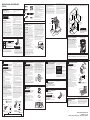
CONEXIÓN DEL CONECTOR
HERRAMIENTAS NECESARIAS MATERIALES NECESARIOS
Ŷ9iOYXODGHFLHUUHSDUDWXEHUtDGHJDV
Ŷ6HOODGRUSDUDMXQWDGHWXEHUtDR8/±FLQWDSDUD
tubería aprobada con Teflón*, resistente a la acción
de gases naturales o propano
Ŷ&RQHFWRUSDUDDUWHIDFWRPHWiOLFRIOH[LEOH´,'
Se recomienda una longitud de 5 pies para una
fácil instalación, pero otras longitudes son
aceptables. Nunca use un conector viejo al instalar
una cocina nueva.
Ŷ$GDSWDGRUSDUDXQLyQFyQLFDSDUDODFRQH[LyQDO
VXPLQLVWURGHJDV´Rò´137[ò´,'
Ŷ$GDSWDGRUSDUDXQLyQFyQLFDSDUDODFRQH[LyQDO
regulador de presión en la cocina
´Rò´137[ò´,'
Ŷ'HWHFWRUGHSpUGLGDGHOtTXLGRRDJXDFRQMDEyQ
*Teflón: Marca registrada por DuPont
Regulador
de presión
)OXMRGHO*DVHQOD&RFLQD )OXMRGHO*DVHQOD&RFLQD
&RQHFWRU
flexible
(6 pies máx.)
$GDSWDGRU
Instalador: Informe al consumidor sobre la ubicación de la válvula de cierre de gas.
Tubería de gas
de ½” o ¾”
$GDSWDGRU
9iOYXODGH
cierre de
gas
Regulador
de presión
&RGR
&RGR
Boquilla
roscada
8QLyQ
Boquilla
roscada
9iOYXOD
de cierre
de gas
Tubería de gas
de ½” o ¾”
Opción
Flexible
Opción de
Tubería Rígida
EN EL COMMONWEALTH DE
MASSACHUSETTS
Ŷ(VWHSURGXFWRGHEHVHULQVWDODGRSRUXQSORPHUR
licenciado o un mecánico gasista.
Ŷ$OXVDUYiOYXODVGHFLHUUHGHJDVWLSREDOyQ
deberán ser del tipo de manija T.
Ŷ$OXVDUXQFRQHFWRUGHJDVIOH[LEOHQRGHEHUi
exceder los 5 pies.
ANTES DE COMENZAR
IMPORTANTE — &RQVHUYHHVWDVLQVWUXFFLRQHV
para uso del inspector de electricidad local.
IMPORTANTE — &XPSODFRQWRGRVORV
códigos y ordenanzas gubernamentales.
IMPORTANTE — Retire todo el material
de embalaje y material escrito del horno antes de
conectar el gas y el suministro de corriente a la cocina.
IMPORTANTE — $ILQGHHYLWDUGDxRV
en los gabinetes, controle con su constructor o
proveedor de gabinetes que los materiales usados
no descolorarán, deslaminarán ni sostendrán otro
GDxR(VWHKRUQRIXHGLVHxDGRGHDFXHUGRFRQORV
UHTXLVLWRVGH8/\&6$,QWHUQDWLRQDO\FXPSOHFRQ
las temperaturas máximas permitidas para gabinetes
GHPDGHUDGH)&
Nota para el Instalador±$VHJ~UHVHGHTXHHVWDV
instrucciones queden en manos del comprador.
Nota para el Consumidor±Guarde estas
instrucciones para referencia futura.
Servicio Técnico±(OGLDJUDPDHOpFWULFRVH
encuentra en un sobre adjunto al reverso de la cocina.
La correcta instalación del producto es
responsabilidad del instalador.
Si se producen fallas en el producto debido a
una instalación inadecuada, la Garantía no cubrirá
las mismas.
$QWHVGHLQVWDODUVXFRFLQDVREUHOLQyOHR\FXDOTXLHU
RWURUHYHVWLPLHQWRGHSLVRVLQWpWLFRDVHJ~UHVHGH
que el revestimiento del piso resista los 180º F sin
contraerse, combarse o descolorarse. No instale la
cocina sobre alfombras, a menos que haya una hoja
de contrachapado de un grosor de ¼” o un aislante
similar entre la cocina y la alfombra.
Casa Rodante – Requisitos de Información
Adicional
Esta cocina se deberá instalar conforme con el
(VWiQGDUGH&RQVWUXFFLyQ\6HJXULGDGSDUD+RJDU
7tWXOR&)53LH]D(anteriormente el
(VWiQGDU)HGHUDOSDUDOD&RQVWUXFFLyQ\6HJXULGDG
GH&DVDV5RGDQWHV)HGHUDO6WDQGDUGIRU0RELOH
+RPH&RQVWUXFWLRQDQG6DIHW\7tWXOR+8'3DUWH
&XDQGRGLFKRHVWiQGDUQRVHDDSOLFDEOH use el
HVWiQGDUSDUDODV,QVWDODFLRQHVGH&DVDV)DEULFDGDV
$16,$1)3$$RFRQFyGLJRVORFDOHV
(Q&DQDGiODLQVWDODFLyQGHHVWDFRFLQDGHEHUi
ser realizada de acuerdo con los estándares
DFWXDOHV&$1&6$$±~OWLPDHGLFLyQRFRQORV
códigos locales.
&XDQGRODFRFLQDHVLQVWDODGDHQXQDFDVDPyYLOVH
GHEHUiDVHJXUDUDOSLVRGXUDQWHHOWUiQVLWR&XDOTXLHU
método para asegurar la cocina es adecuado,
siempre y cuando se realice conforme con los
estándares que figuran a continuación.
ADVERTENCIA
RIESGO DE INCENDIO O
EXPLOSIÓN
Si la información de este manual no se sigue
exactamente, se podrá producir un incendio o
H[SORVLyQRFDVLRQDQGRGDxRVVREUHODSURSLHGDG
lesiones o la muerte.
La instalación deberán ser realizadas por un
instalador calificado.
Lea estas instrucciones en su totalidad y atentamente.
Esta cocina se deberá instalar de acuerdo con
los códigos locales, o en la ausencia de códigos
ORFDOHVFRQHO&yGLJRGH*DV&RPEXVWLEOH1DFLRQDO
$16,=1)3$~OWLPDHGLFLyQ(Q&DQDGi
ODLQVWDODFLyQGHEHUiVHUFRQIRUPHFRQHO&yGLJRGH
,QVWDODFLyQGH*DV1DWXUDODFWXDO&$1&*$%
RHO&yGLJRGH,QVWDODFLyQGH3URSDQRDFWXDO&$1
&*$%\FRQORVFyGLJRVORFDOHVFXDQGR
FRUUHVSRQGD(VWDFRFLQDIXHGLVHxDGD\FHUWLILFDGDSRU
&6$,QWHUQDWLRQDOGHDFXHUGRFRQ$16,=~OWLPD
HGLFLyQ\FRQOD&DQDGLDQ*DV$VVRFLDWLRQ$VRFLDFLyQ
GH*DVGH&DQDGi&$1&*$~OWLPDHGLFLyQ
$OLQVWDODUXQHOHFWURGRPpVWLFRDJDVHOXVRGH
conectores flexibles viejos puede ocasionar pérdidas
y lesiones personales. Siempre use un conector
IOH[LEOH18(92
La prueba de goteras del electrodoméstico se
deberá realizar de acuerdo con las instrucciones del
fabricante.
La cocina deberá estar correctamente conectada
a tierra de acuerdo con los códigos y ordenanzas
locales o, en ausencia de códigos locales, de acuerdo
FRQHO&yGLJR1DFLRQDOGH(OHFWULFLGDG1DWLRQDO
(OHFWULF&RGH$16,1)3$12~OWLPDHGLFLyQ
(Q&DQDGiODFRQH[LyQDWLHUUDVHGHEHUiUHDOL]DUGH
DFXHUGRFRQOD3DUWHGHO&yGLJRGH(OHFWULFLGDGGH
&DQDGi&6$&\RORVFyGLJRVORFDOHV(QHVWD
VHFFLyQFRQVXOWHODV&RQH[LRQHV(OpFWULFDV
No instale este producto con una campana con cortina
de aire u otra campana de cocina que funcione llevando
aire a la placa de cocción. El flujo de aire podrá
interferir en el funcionamiento de los quemadores de
gas, produciendo riesgos de incendio o explosión.
1
SUMINISTRO DE GAS
ADVERTENCIA
Riesgo de incendio:
No use una llama para controlar las pérdidas de gas.
ADVERTENCIA
Riesgo de
Explosión: No supere una torsión máxima de 25
pies-libras al realizar conexiones de tuberías de
gas. Cualquier ajuste en exceso podrá romper
el regulador de presión, resultando en riesgo de
incendio o explosión.
Regulador de Presión de Gas
Se deberá usar el regulador de presión de gas
suministrado con esta cocina. Para un funcionamiento
adecuado, la presión de entrada al regulador deberá
ser la siguiente:
Gas Natural:
3UHVLyQPtQLPD&ROXPQDGH$JXDGH´
3UHVLyQPi[LPD&ROXPQDGH$JXDGH´
Gas Propano:
3UHVLyQPtQLPD&ROXPQDGH$JXDGH´
3UHVLyQPi[LPD&ROXPQDGH$JXDGH´
Si no está seguro sobre cuál es la presión de entrada,
comuníquese con el proveedor de gas local.
Cierre la válvula principal de suministro de gas
antes de desconectar su vieja cocina y deje la
misma apagada hasta que la nueva conexión se
haya completado. No olvide volver a encender el
piloto en otros electrodomésticos a gas cuando
vuelva a encender el gas.
Debido a que las tuberías duras restringen el
movimiento de la cocina, se recomienda el uso del
conector para electrodomésticos de metal flexible con
FHUWLILFDFLyQLQWHUQDFLRQDOGH&6$DPHQRVTXHORV
códigos locales requieran una conexión de tubería dura.
Si se usa el método de tubería dura, deberá alinear la
misma con cuidado; la cocina no se podrá mover una
vez realizada la conexión.
Para evitar pérdidas de gas, coloque el compuesto
de la junta de gas, o envuelva la cinta para roscas de
tuberías con Teflón* alrededor de todas las roscas de
tubería macho (externas).
$,QVWDOHXQDYiOYXODGHFLHUUHPDQXDOGHODOtQHDGH
gas en la línea de gas, en una ubicación de fácil
DFFHVRIXHUDGHODFRFLQD$VHJ~UHVHGHTXHWRGDV
las personas que usen la cocina sepan dónde y
cómo cerrar el suministro de gas de la cocina.
%,QVWDOHHODGDSWDGRUGHODXQLyQFyQLFDPDFKRGH
½” a la rosca interna de 1/2” de NPT en la entrada
GHOUHJXODGRU8VHODOODYHGHUHSXHVWRHQHO
DFFHVRULRUHJXODGRUSDUDHYLWDUGDxRV
$OLQVWDODUODFRFLQDGHVGHHOIUHQWHUHWLUHHOFRGR
de 90º para una instalación más fácil.
&,QVWDOHXQDGDSWDGRUSDUDXQLyQFyQLFDGHò´Rô´
a la rosca interna de NPT de la válvula de cierre
manual, procurando evitar que la válvula de cierre
no gire.
'&RQHFWHHOFRQHFWRUGHPHWDOIOH[LEOHGHO
electrodoméstico al adaptador de la cocina.
Posicione la cocina para permitir la conexión en la
válvula de cierre.
(&XDQGRWRGDVODVFRQH[LRQHVVHKD\DQUHDOL]DGR
DVHJ~UHVHGHTXHWRGRVORVFRQWUROHVGHODFRFLQD
estén en la posición de apagado y encienda
ODYiOYXODGHVXPLQLVWURSULQFLSDOGHJDV8VH
un detector de pérdida de líquido en todas las
uniones y conexiones, para controlar pérdidas en
el sistema.
$OXVDUSUHVLyQVXSHULRUDòSVLJSDUDFRQWURODU
la presión del sistema de suministro de gas de la
residencia, desconecte la cocina y la válvula de
cierre individual de la tubería de suministro de gas.
$OXVDUODVSUHVLRQHVGHSUXHEDGHòSVLJRPHQRV
para controlar el sistema de suministro de gas,
simplemente aísle la cocina del sistema de suministro
de gas, cerrando la válvula de cierre individual.
$OFRQWURODUHOIXQFLRQDPLHQWRDGHFXDGRGHOUHJXODGRU
la presión de entrada deberá ser por lo menos 1”
mayor que la presión de funcionamiento (tubo) como
en la etiqueta de calificación del producto.
*Teflón: Marca registrada por DuPont
2
CONEXIONES ELÉCTRICAS
ADVERTENCIA
Riesgo de
Descarga: Este electrodoméstico deberá estar
conectado a tierra de forma adecuada. Si no cumple
con esto se podrán producir descargas eléctricas.
Requisitos Eléctricos - &LUFXLWRGHYROWLRV
+HUW]FRUUHFWDPHQWHFRQHFWDGRDWLHUUDSRUXQ
disyuntor de 15 o 20 amperes o fusible de retraso. Se
recomienda contar con un circuito separado que se
XVH~QLFDPHQWHFRQHVWDFRFLQD
Nota: No se recomienda para este producto el
uso de interruptores automáticos, inalámbricos o
con cableado externo que apagan la corriente del
electrodoméstico.
Conexión a Tierra
El cable de corriente de este electrodoméstico cuenta
con un enchufe de 3 patas (conexión a tierra) que
se conecta a un tomacorriente de pared estándar de
3 cables para minimizar la posibilidad de riesgos de
descargas eléctricas por parte del mismo.
El cliente deberá contratar a un electricista calificado
para que controle el circuito, a fin de asegurar que el
tomacorriente esté correctamente conectado a tierra.
En caso de contar con un tomacorriente de pared de
2 cables, es la responsabilidad y obligación del cliente
reemplazarlo por un tomacorriente de pared de 3
cables correctamente conectado a tierra.
NUNCA, BAJO NINGUNA CIRCUNSTANCIA,
CORTE NI ELIMINE EL TERCER CABLE (TIERRA)
DEL CABLE DE CORRIENTE. NO USE UN
ADAPTADOR. NO USE UN PROLONGADOR.
1RVHUHTXLHUHQQLVHUHFRPLHQGDQ,QWHUUXSWRUHVFRQ
'HWHFFLyQGH)DOODD7LHUUD*)&,HQUHFHSWiFXORVGH
cocinas a gas. El funcionamiento de la cocina no se
YHUiDIHFWDGRVLVHXWLOL]DHQXQFLUFXLWR*)&,SURWHJLGR
pero es posible que se produzcan detenciones
RFDVLRQDOHVQRGHVHDGDVGHOLQWHUUXSWRU*)&,
PARA SU SEGURIDAD
$VHJ~UHVHGH
contar con una
conexión a tierra
adecuada antes
de usar.
CUANDO TODAS LAS
CONEXIONES SE HAYAN
COMPLETADO
$VHJ~UHVHGHTXHWRGRVORVFRQWUROHVTXHGHQHQOD
SRVLFLyQGHDSDJDGR$VHJ~UHVHGHTXHHOIOXMRGHOD
combustión y el aire de ventilación a la cocina estén
desobstruidos.
$VHJ~UHVHTXHWRGRVORVPDWHULDOHVGHHPSDTXH\
cintas se hayan retirado. Esto incluye cintas sobre
el panel metálico debajo de las perillas de control (si
corresponde), cinta adhesiva, cintas de ajuste, cartón
y plástico protector. Si estos materiales no se retiran,
VHSRGUiSURGXFLUFRPRUHVXOWDGRXQGDxRVREUHHO
electrodoméstico, una vez que el mismo haya sido
encendido y las superficies estén calientes.
6
INSTALE Y CONTROLE EL
DISPOSITIVO
ANTIVOLCADURAS
ADVERTENCIA
Nunca retire
completamente las patas niveladoras, ya que la
cocina no estará asegurada de forma adecuada al
dispositivo antivolcaduras.
Siga las instrucciones suministradas con el soporte
$17,92/&$'85$6
Kit de soporte
anti-volcaduras
incluido
ADVERTENCIA
$QWHVGH
comenzar la instalación, apague el encendido
en el panel de servicio y bloquee el medio de
desconexión del servicio a fin de evitar que
el encendido se active de forma accidental.
&XDQGRHOPHGLRGHGHVFRQH[LyQGHOVHUYLFLR
no se pueda bloquear, ajuste de manera segura
un ítem de advertencia que esté bien visible, tal
como una etiqueta, sobre el panel de servicio.
Kit de soporte
anti-volcaduras incluido
Si no recibió un soporte anti volcaduras con su compra,
llame al 1.800.626.8774 para recibir uno sin costo.
(Q&DQDGiOODPHDO3DUDUHFLELU
instrucciones de instalación del soporte, visite:
*($SSOLDQFHVFRP(Q&DQDGi*($SSOLDQFHVFD
Destornillador con
cabeza plana
Llave para tubería (2)
(una de repuesto)
Destornillador Philips
Llave con extremo
abierto o ajustable
Lápiz y regla
Nivel
Taladro, punzón
o clavo
INSTRUCCIONES DE INSTALACIÓN
31-10893-6 01-20 GEA
JGBS10, JGBS30, JGBS60, JGBS61, JGB450, JGB635, y XGB635
3
SUPERFICIALES
UEMADORES
ADVERTENCIA
Riesgo de Incendio
o Explosión: No use el quemador sin que todas
las partes de los quemadores estén en sus
respectivos lugares.
$ Quemadores -&RORTXHODVFDEH]DVGHORV
quemadores en las posiciones correspondientes
en la placa de cocción.
B. Tapas - &RORTXHODVWDSDVHQORVTXHPDGRUHVGH
ORVWDPDxRVFRUUHVSRQGLHQWHV
& Rejillas - Las rejillas izquierda y derecha son
LQWHUFDPELDEOHV&RORTXHODVUHMLOODVHQODSODFD
de cocción.
7
NIVELACIÓN DE LA COCINA
ADVERTENCIA
Nunca retire
completamente las patas niveladoras, ya que la
cocina no estará asegurada de forma adecuada al
dispositivo anti-volcaduras.
A. Enchufe la unidad.
B. Mida la altura de su mostrador de encimera en la
parte trasera de la abertura (X).
C. $MXVWHODVGRVSDWDVGHQLYHODFLyQWUDVHUDVSDUD
que la parte trasera de la estufa se encuentre a la
misma altura o más arriba que la mesada (Y).
D. Deslice la unidad en su lugar.
E. ,QVWDOHORVHVWDQWHVGHOKRUQRHQODXQLGDG\
coloque la cocina donde se instalará.
F. &RQWUROHODQLYHODFLyQFRORFDQGRXQQLYHOGH
burbuja de aire sobre uno de los estantes
GHOKRUQR+DJDGRVOHFWXUDV±FRQHOQLYHOXELFDGR
en diagonal primero en una dirección
y luego en la otra.
G. $MXVWHODVSDWDVGHQLYHODFLyQIURQWDOHVKDVWDTXH
la cocina quede nivelada.
H.
2EVHUYHGHEDMRGHODXQLGDG\YHULILTXHTXHOD
pata trasera esté completamente adherida al
dispositivo antivolcaduras. De no ser así, retire la
unidad y ajuste la altura de la pata trasera de modo
que quede correctamente adherida.
1LYHOGH$JXD
Instrucciones de instalación
Cocina
• Un niño o adulto pueden volcar la cocina y morir.
• Instale el soporte anti-volcaduras sobre la pared o el piso.
•
Asegúrese la estufa al soporte anti-volcaduras deslizando
la unidad hacia atras de tal manera que la pata niveladora
sea enganchada.
• Vuelva a adherir el soporte anti-volcaduras si la estufa
se mueve de lugar.
• Si esto no se hace, se podrá producir la muerte o
quemaduras graves en niños o adultos.
Riesgo de Caída
ADVERTENCIA
Placa de
clasificación
HORNO SIMPLE
NOTA: La placa de cocción debe estar a la
misma altura o más arriba que la mesada.
Mesada
0” o Superior
Placa de
&RFFLyQ
Electrodo
Tapa
Quemador
CONVERTIR A GAS PROPANO
(O VOLVER A CONVERTIR DE
PROPANO A GAS NATURAL)
Esta cocina deja la configuración de fábrica para
uso con gas natural. Si desea convertir a gas
propano, la conversión deberá ser realizada por
un instalador de gas propano calificado.
Los orificios de conversión y las instrucciones se
podrán encontrar en la parte trasera de la cocina.
Guarde estas instrucciones y todo orificios en caso
de que lo desee convertir nuevamente a gas natural.
PRECAUCIÓN
Para
evitar que una corriente de aire afecte
el funcionamiento del quemador, selle
todas las aberturas sobre el piso
debajo del electrodoméstico y detrás
de la pared del mismo.
DIMENSIONES Y ESPACIOS
(CONT.)
UBICACIONES DE LA TUBERÍA DE GAS Y DEL TOMACORRIENTE ELÉCTRICO
INSTALACIÓN EN ALTITUDES ELEVADAS
$PiVGHSLHVHOSURGXFWRFRQILJXUDGRSDUDJDVQDWXUDORSURSDQRUHTXLHUHODLQVWDODFLyQGHONLW
:%;SDUDJDVQDWXUDO\:%;SDUDJDVSURSDQR6LJDODVLQVWUXFFLRQHVLQFOXLGDVFRQHONLW
18”
$OWXUDPtQLPD
hasta los gabinetes
sobre la mesada
0”
$OWXUDPtQLPD
hasta los
gabinetes
debajo de la
superficie de
cocción
30”
Mínimo
30”
13”
$OWXUD
máxima
hasta los
gabinetes
sobre la
mesada
2” Lado derecho
2” Lado izquierdo
$OWXUDPtQLPDKDVWD
la pared lateral
36”
30”
2”
5”
4”
9”
13”
14 1/2”
24”
4 1/2”
12 1/2”
Pared Lateral
Suministro
de gas y
electricidad
5
CONTROLE LOS
QUEMADORES PARA
HONEAR Y ASAR
ŶConfigure la función Bake (Hornear) en 350º F.
El quemador se deberá iluminar entre 30 y 60
segundos.
Ŷ&RQILJXUHDVDUHQ%URLO+L$VDGR$OWR(O
quemador se deberá iluminar en un tiempo de entre
30 y 60 segundos.
4
CONTROLE LAS CABEZAS
DE LOS QUEMADORES
3UHVLRQH\JLUHODSHULOODDODSRVLFLyQ/,7(/X]8Q
sonido de clic indica el correcto funcionamiento del
VLVWHPDGHHQFHQGLGR$OLOXPLQDUFXDOTXLHUTXHPDGRU
se producirán chispas en todos los quemadores pero
VyORVDOGUiJDVGHOTXHIXHVHOHFFLRQDGR8QDYH]
que el aire se haya purgado de la línea de suministro,
el quemador se deberá encender dentro de los 4
segundos. Luego de que el quemador se encienda,
JLUHODSHULOODIXHUDGHODSRVLFLyQ/,7(/X]3UXHEH
cada quemador de forma sucesiva hasta que todos los
quemadores hayan sido controlados.
Calidad de las Llamas
Determine la calidad de las llamas de forma visual.
Las llamas normales de los quemadores se deberán
YHUFRPR$R%
Las llamas largas de color amarillo brillante no son
normales. Las llamas normales podrán mostrar signos
de un tinte anaranjado cuando estén bien quemadas,
o signos de anaranjado parpadeante debido a las
partículas del gas o del aire.
(A) Llamas azul suave —
Normal para gas natural
(B) Puntas amarillas en
conos externos — Normal
para el gas propano
Parte Trasera de la Estufa
.LWGHO2ULILFLR
(la ubicación
puede variar)
7RSHVGH8ELFDFLyQ
X
Y
30"
46 1/4"
28 3/4"
w/ handle
26 1/4"
w/o handle
10 1/4"
36 1/4 " ± 1/4
Sin manija
&RQPDQLMD
-
 1
1
-
 2
2


En otros idiomas
- English: GE JGBS60DEKWW Installation guide