Bosch HBL5351UC/02 Guía de instalación
- Categoría
- Hornos
- Tipo
- Guía de instalación

Built-In Oven
Installation Manual
500/800/Benchmark TMSeries
HBL5351UC, HBL5451UC, HBL5551UC, HBL5651UC,
HBL8451UC, HBL8461UC, HBL8651UC, HBL8661UC,
HBLP451LUC, HBLP451RUC, HBLP451UC, HBLP651LUC,
HBLP651RUC, HBLP651UC, HBN5451UC, HBN5651UC,
HBN8451UC, HBN8651UC
""-_BOSCH
_,_F- 'i
" 'F-_'J
Invented for life
|

Table of Contents
Safety Definitions ............... 1
Safety Information ............... 1
Preparation .................... 3
Before You Begin ..................... 3
Tools and Parts Needed ................ 3
Parts Included ........................ 3
General Information .................... 3
Dimensions and Cabinet
Requirements .................. 4
Removing Packaging ............ 4
Preparing Oven ....................... 4
Installation ..................... 5
Electrical Installation ................... 5
Installing the Oven Unit into the Wall
Cabinet ............................. 6
For Best Installation .................... 6
Correct Inside Oven Lift Point ............ 6
Installing the Oven ..................... 8
Bottom Hinge Doors Only - Remove Prior to
Install ............................... 8
Installing the Oven into the Cabinet
(all ovens) ........................... 9
Ovens with Bottom Hinge Doors Only ..... 10
Ovens with Side Hinge Doors Only ....... 10
Before Calling Service ................. 13
Cabinet Dimension Requirements. 15
Dimensions for 27" Single Oven Units .. 15
Single Oven 27" Traditional Installation, Cabinet
and Undercounter .................... 15
Single Oven 27" Flush Mount Installation .. 15
Dimensions for 27" Double Oven Units .. 15
Double Oven 27" Traditional Installation ... 15
Double Oven 27" Flush Mount Installation .. 16
Dimensions for 30" Single Oven Units .. 16
Single Oven 30" Traditional Installation,
Cabinet and Undercounter .............. 16
Single Oven 30" Flush Mount Installations 16
Dimensions for 30" Double Oven Units .. 17
Double Oven 30" Traditional Installation ... 17
Double Oven 30" Flush Mount Installion ... 17
This Bosch Appliance is made by
BSH Home Appliances Corporation
1901 Main Street, Suite 600
Irvine, CA 92614
Questions?
1-800-944-2904
www.bosch-home.com/us
We look forward to hearing from you!

IMPORTANT SAFETY INSTRUCTIONS
READ AND SAVE THESE INSTRUCTIONS
Safety Definitions
WARNING
This indicates that death or serious injuries may
occur as a result of non-observance of this warning.
CAUTION
This indicates that minor or moderate injuries may
occur as a result of non-observance of this warning.
Appliance Handling Safety
Do not lift appliance by door handle. Remove the door for
easier handling and installation. See instructions in Use
and Care Manual.
Unit is heavy and it is recommended that at least two
people for single ovens and at least three people for double
ovens be used.
Hidden surfaces may have sharp edges. Use caution when
reaching behind or under appliance.
Unpacking the Oven
NOTICE: This indicates that damage to the appliance or
property may occur as a result of non-compliance with this
advisory.
Note: This alerts you to important information and/or tips.
Unpack the oven, remove all tape and packaging material
and examine the oven for any damage such as dents,
broken door latches or cracks in the door. Notify dealer
immediately if oven is damaged. Do not install if oven is
damaged.
Safety Information
IMPORTANT: SAVE THESE INSTRUCTIONS FOR THE
LOCAL INSPECTOR'S USE.
INSTALLER: LEAVE THESE INSTRUCTIONS WITH THE
APPLIANCE AFTER INSTALLATION IS COMPLETE.
OWNER: PLEASE RETAIN THESE INSTRUCTIONS FOR
FUTURE REFERENCE.
_, WARNING
If the information in this manual is not followed
exactly, fire or shock may result causing property
damage or personal injury.
WARNING
Do not repair or replace any part of the appliance
unless specifically recommended in the manuals.
Improper installation, service or maintenance can
cause injury or property damage. Refer to this
manual for guidance. All servicing should be done
by a qualified technician.
Safety Codes and Standards
This appliance complies with one or more of the following
Standards:
• UL 858, Household Electric Ranges
• UL 923, Microwave Cooking Appliances
• UL 507, The Standard for the Safety of Electric Fans
• CAN/CSA-C22.2 No. 113-M1984 Fans and Ventilators
It is the responsibility of the owner and the installer to
determine if additional requirements and/or standards
apply to specific installations.
Electric Safety
Before you plug in an electrical cord, be sure all controls
are in the OFF position.
If required by the National Electrical Code (or Canadian
Electrical Code), this appliance must be installed on a
separate branch circuit.
Installer - show the owner the location of the circuit
breaker or fuse. Mark it for easy reference.
Important - Save these instructions for the local electrical
inspector's use.
Before installing, turn power OFF at the service panel. Lock
service panel to prevent power from being turned ON
accidentally.
9001065629 Rev A English 1

IMPORTANT SAFETY INSTRUCTIONS
READ AND SAVE THESE INSTRUCTIONS
Refer to data plate for more information. See "Data Plate"
under "Service" for data plate location.
Be sure your appliance is properly installed and grounded
by a qualified technician. Installation, electrical connections
and grounding must comply with all applicable codes.
Related Equipment Safety
Remove all tape and packaging before using the appliance.
Destroy the packaging after unpacking the appliance.
Never allow children to play with packaging material.
Never modify or alter the construction of the appliance. For
example, do not remove leveling legs, panels, wire covers
or anti-tip brackets/screws.
Transport
To avoid damage to the oven vent, use the transport
method shown in the picture below.
Support the bottom of the oven from side to side when
moving it into the installation location. Leave the unit
attached to the shipping pallet until it is in front of the
cabinet opening, ready to lift into place.
English 2 9001065629 Rev A

Preparation
Before You Begin
Tools and Parts Needed
• Phillips head screwdriver
• Star-head screwdriver (T20)
• Measuring tape
• Drill with bit (1/8")
• Gloves
Parts Included
• Phillips head screws (6)
General Information
Power Requirements
The outlet must be properly grounded in accordance with
all applicable codes.
For Best Installation
The oven can be difficult to handle during installation. It is
recommended to have three or more people available to
assist with lifting the unit into place.
Removal of the bottom hinge oven door during installation
(to provide the necessary handholds and to significantly
reduce the unit weight) can be cumbersome unless the
detailed door removal instructions are followed carefully.
Note: Do not attempt to remove the side hinge door (some
models).
Please take time to read and follow the instructions
provided for an improved installation experience.
Use this checklist to verify that you have completed each
step of the installation process. This can help you avoid
mistakes.
__ 1. Before installing the oven, be sure to verify the
cabinet dimensions are correct for your unit and
the required electrical connections are present.
, Refer to the installation manual for content
regarding Safety, Cabinet Dimensions, Removing
Packaging, Electrical Installation, Testing the
Installation and Customer Service.
__ 3. Remove bottom hinged oven door(s) (not side
swing doors) to reduce the unit weight and to
provide access to handholds for lifting.
__ 4. Move the oven unit into place in front of the cabinet
opening, leaving the bottom packaging on the unit
to avoid damaging flooring.
__ 5. Remove the torx head (T-20 size) screws holding
the unit to the base of the carton (using Star-head
screwdriver).
,
Team lift the unit directly into the cabinet cutout
taking care not to pinch fingers or scratch hands or
arms. Make sure the electrical conduit reaches to
the connection point properly.
__ 7. Slide the unit all the way into place, making sure to
route the electrical conduit correctly.
__ 8. Fasten the oven unit to the cabinetry opening with
the screws supplied (using Philips screwdriver).
__ 9. Reinstall the oven door(s) removed in step 3
above.
__ 10. Consult the complete installation instructions and
follow the remainder of the procedures listed,
including performing an operation test.
__ 11. All product literature and accessories (may be
wrapped or boxed) with the oven.
__ 12. INSTALLER - Leave the literature pack and the
accessories with the customer.
9001065629 Rev A English 3

Dimensions and Cabinet Requirements
Cabinet requirements vary depending on the model to be
installed. Please consult the "Cabinet Dimension
Requirements" section at the back of this installation
manual for the details pertaining to your particular model.
All models require:
1/4" (6.4 mm) space between the side of the oven and
an adjacent wall or cabinet door when installed at the
end of a cabinet run.
Installation of 2x4's extending front to back flush with
the bottom and side of the opening to provide oven
support. This supporting base must be well secured to
the floor/cabinet and must be level.
The electrical conduit box must be located above the
unit to facilitate connecting and servicing the unit.
The cabinet base must be flat and capable of
supporting the weight of your oven when in use (varies
by model up to 390 Ibs. (177 kg)). See the appropriate
weight for your model in the "Cabinet Dimensions
Requirements" section at the back of this installation
manual.
Removing Packaging
• Cut straps on the outside of the box.
• Remove the cardboard box by lifting it up and off the
unit.
• Remove all top and side cardboard and Styrofoam
braces.
• Place the oven (leaving it on the shipping base) in front
of the cabinet where it is to be installed.
Remove all accessories, racks, packing materials and
literature from the oven cavity (for double ovens,
remove such items, if present, from both cavities).
Unscrew unit from packaging brackets as shown below
in "Packaging Bracket Removal."
Note: The screws near the base mounting bracket are
all torx head (T-20 size). Only the one screw that goes
through the slotted hole in the mounting bracket on the
left and right sides of the unit needs to be removed in
order to lift the unit from the mounting base (the screw
circled and shown as "A" in the following illustration.)
NOTICE
Remove one screw only from each bracket. This
will release the oven from the shipping base. Do
not remove any additional screws from the oven.
Packaging Bracket Removal (left and right
sides)
Note:
Different models use different packaging materials. Actual
brackets may look differently. The bracket remains in the
packaging base. The unit should stay on the packaging
base until ready to be lifted into cabinet cutout.
Preparing Oven
Place oven in front of the cabinet where it is to be installed
so that it is in line with the cabinet cutout.
Check to be sure all packing materials have been removed
from the unit. Also remove the accessories, oven racks,
literature pack and any shipping materials from inside the
oven cavity (remove from both cavities for a double oven or
combination oven).
English 4 9001065629 Rev A

Installation
This installation manual provides instructions for the
installation of single ovens and double ovens.
Electrical Installation
All model ovens on the front cover of this installation
instruction manual are dual rated, designed to be
connected to either 208 or 240V AC, 60 Hz, 4 wire, single-
phase power supply.
Model Circuit Required
208V, 60 Hz 240V, 60 Hz
HBN54, HBN84,
HBL53, HBL54, 30 AMP
HBL84, HBLP4
HBL55 30 AMP / 40 AMP
£
HBN56, HBL56,
HBN86, HBL86, 40 AMP
HBLP6
The electrical supply should be a 4-wire single-phase AC.
Install a suitable conduit box (not furnished). An
appropriately-sized, UL-listed conduit connector must be
used to correctly attach the conduit to the junction box.
Important: Local Codes may vary; installation, electrical
connections and grounding must comply with all applicable
local codes.
If local codes permit grounding through the electrical
supply neutral, connect both the white neutral wire and the
green ground wire from the oven to the white neutral
electrical supply wire.
Electrical Connection to Main Power Supply
The four-wire connection is preferred, but where local
codes permit, the three wire connection is also acceptable.
Four-wire Connection
Ungrounded Neutral
power supply
junction box
red wires
green or bare
wire
black wires
green wire white wires
UL listed
-"................ cable from
connector
oven
• Connect the red oven wire to the red electrical supply
wire (hot wire).
• Connect the black oven wire to the black electrical
supply wire (hot wire).
• Connect the white neutral oven wire to the white
neutral (not bare or green ground) electrical supply
wire.
• Connect the green ground oven wire to the bare or
green ground electrical supply wire.
Three-wire Connection
Grounded Neutral
power supply t.
junction box .
red wires ---__._
white, bare, or
green wire
white wire
green wire
-i
black wires
UL listed
connector
cable from
oven
• Connect red wire from oven to red wire in junction box.
• Connect black wire from oven to black wire in junction
box.
Connect both green ground wire and white wire from
oven to white, green or bare neutral wire in junction
box.
The conduit cable, where connected at the oven, swivels.
Rotate conduit cable upward (or downward) and direct
through hole prepared in cabinet to attach to the junction
box.
To maintain serviceability, the flex conduit must not be
shortened and should be routed to permit temporary
removal of the oven.
9001065629 Rev A English 5

Installing the Oven Unit into
the Wall Cabinet
NOTICES
Before installing the oven, be sure to verify the
cabinet dimensions and electrical connections.
Check that the cabinet opening is level and plumb
for correct installation.
For Best Installation
It is recommended to remove the oven door (bottom hinge
models only) to help reduce the unit weight and provide
easier access to the handholds located inside the oven.
Caution
It is recommended to wear gloves and long sleeves to
protect hands and forearms from abrasion and potential
scratches during the lifting process. It is also recommended
to take off watches and jewelry and to wear work shoes
during installation for foot protection.
Correct Inside Oven Lift Point
Notice: DO NOT attempt to lift the unit by holding the oven
upper element.
There is a ridge across the top front of the oven cavity. Lift
by grasping this ridge with one hand while placing the other
hand on the back of the unit (for helpers lifting from the
sides of the unit). If a third helper is lifting from the front,
both hands should lift by holding this ridge area.
English 6 9001065629 Rev A

Lifting Recommendations Vary Dependent Upon Oven Door Type
Bottom Hinge Door
Lift Locations (with door(s) removed)
Lift points (1) on the front of the unit are for lifting from the
sides of the unit. Lift point (3) on the front of the unit is for a
third person to help lift the unit.
Lift point (2) on the back of the unit shows the location of
the opposite hand for the helpers lifting from the sides of
the unit. Adjust the location as needed to facilitate the lift.
Wear gloves, a long sleeved shirt, and avoid sharp edges
to reduce the risk of cuts or abrasions to the arms or hands.
Single Oven Double Oven
I
[_ J
O
Side Hinge Door
Lift Locations (with lower door opened to 90°-110 °)
Lift points (1) on the front of the unit are for lifting from the
sides of the unit. Lift point (3) on the front of the unit is for a
third person to help lift the unit.
Lift point (2) on the back of the unit shows the location of
the opposite hand for the helpers lifting from the sides of
the unit. Adjust the location as needed to facilitate the lift.
Wear gloves, a long sleeved shirt, and avoid sharp edges
to reduce the risk of cuts or abrasions to the arms or hands.
Single Oven - Side Swing Double Oven Side Swing
9001065629 Rev A English 7

Installing the Oven
WARNING
• Make sure oven is cool and power to the oven
has been turned off before removing the door.
Failure to do so could result in burns.
• The oven door is heavy and fragile. Use both
hands to remove the oven door. The door front
is glass. Handle carefully to avoid breaking.
• Grasp only the sides of the oven door. Do not
grasp the handle as it may swing in your hand
and cause damage or injury.
• Failure to grasp the oven door firmly and
properly could result in personal injury or
product damage.
• To avoid injury from hinge bracket snapping
closed, be sure that both levers are securely in
place before removing the door. Also, do not
force door open or closed - the hinge could be
damaged and injury could result.
• Do not lay removed door on sharp or pointed
objects as this could break the glass. Lay on a
flat, smooth surface, positioned so that the
door cannot fall over.
Bottom Hinge Doors Only - Remove
Prior to Install
Important: Do not attempt to remove the side hinge
door (side hinge doors are found only on select models).
Ovens with bottom hinge doors permit the oven door(s) to
be removed prior to lifting the unit into place. Each door
weighs approximately 40 pounds (18.1 kg). Removing and
replacing the door are routinely simple procedures.
Removing the door lightens the unit significantly and
provides easier access to the recommended handhold
inside the oven cavity. See instructions below.
, Be sure to read all
warnings and cautions
in the installation
manual regarding the
door removal before
attempting to remove
the door.
2. Open the door
completely.
3. Flip latch levers on
hinges toward you.
,
Holding the door firmly
on both sides and
using both hands,
close the door gently
until it stops against
the latch levers, about
30° from the closed
position.
,
Carefully lift the door
up and out of the
hinge slots. Hold
firmly; the door is
heavy.
, Place the door in a
convenient and stable
location until you are
ready to reinstall it.
Lay the door on a
towel or section of
protective foam
padding to avoid
damage to the door or
the floor.
Placing the Oven Unit Into the Cabinet
Opening
CAUTION
To avoid damage to the door do not lift, pull or push
the unit during installation by using the oven door
handle as a gripping point.
It is recommended to wear gloves and long sleeves
to protect hands and forearms from abrasion and
potential scratches during the lifting process. It is
also recommended to take off watches and jewelry
and to wear work shoes during installation for foot
protection.
When lifting the unit into place avoid grasping the upper
element to avoid damaging it. See the illustration following
for the correct lifting point for a bottom hinge double oven
with the lower door removed. This illustration shows a
detailed view of the oven cavity. Note the location of the
ridge inside the top of the cavity. This is the area to grip
from the front when lifting the oven.
For your particular oven type, see the preceeding section
"Lifting Recommendations Vary Dependent Upon Oven
Door Type" for lift points.
English 8 9001065629 Rev A

Installing the Oven into the Cabinet (all
ovens)
1. The unit and its bottom packaging (wood and
styrofoam base) should be positioned close to and in
front of the cabinet opening prior to beginning to lift the
unit into place.
2. Lift or slide unit into the cabinet cutout without allowing
the unit base to contact the flooring.
3. Check that the conduit cable does not fall behind the
unit during installation. It may help to run the conduit
into the area it will be connected to (such as an
overhead or adjacent cabinet) and tape the end down
so it doesn't fall out while the unit is being slid into
place.
4. Guide the unit straight back into the cabinet cutout.
Note: Be careful not to crimp the flexible conduit
between the oven and the cabinet back wall. If
necessary, guide the flexible conduit into the wall or
cabinet access hole so it doesn't prevent the unit from
being pushed all the way into the cabinet opening. The
oven should be straight and level, not crooked.
5. Push the unit straight in until the oven trim is flush with
the front of the cabinet trim.
6. Install supplied screws through tap holes in trim.
(2 screws for single ovens, 4 screws for double ovens).
9001065629 Rev A English 9

Ovens with Bottom Hinge Doors Only Ovens with Side Hinge Doors Only
Re-Install the oven doors:
" 'iii
1. Hold the door firmly in
both hands.
, Hold the door at a 30°
angle from the closed
position and insert
hinges into the slots.
You may need to rock
the door forward and
backward slightly to
seat the hinge feet.
,
The door may need to
be removed and re-
inserted until the
hinges sit correctly in
the slots.
4. Open door all the way
to expose hinges,
latch levers, and slots.
5. Push latch levers
forward and down until
seated on the bracket.
,
Close and open door
slowly to be sure it is
correctly and securely
in place. Door must be
straight, not crooked.
Side Hinge Door Aligment
Note: Only align the side hinge oven doors after the unit is
fully installed into the cabinet.
Fig. A
Fig. B
,
,
,
Check to see if the
side hinge oven doors
are properly aligned.
The door should pull
itself closed smoothly
when the striker
engages the roller as
the door is closed.
Too high (Fig. A - door
needs to move down
on latch side) you will
feel interference
between the striker
and the catch receiver.
Too low (Fig. B - door
needs to move up on
latch side) you will feel
a bump when the
striker comes into
contact with the re-
alignment roller.
Hint: The gap between
the top of the closed
oven door and the
control panel (or upper
door for lower cavities
in double ovens)
should be fairly
uniform from side to
side.
English 10 9001065629 Rev A

Side Hinge Door Alignment Procedure
Open the door to
approximately 135°.
Using a Torx T-20 star-
head screwdriver,
loosen the 3 screws
(A) on the lower hinge
by 1 to 2 full turns.
Note: All adjustment is
made with the lower
hinge only. The upper
hinge is fixed in place
and cannot be
adjusted.
,
Using a #2 philips
head screwdriver, turn
the cam (B) right or left
to adjust the hinge
position in the desired
direction.
Note: lmm of hinge
movement (left or
right) will move the
door up or down
approximately 1.5mm
at the door catch.
4. Re-tighten the screws
before closing the
door to test. Be careful
not to overtighten.
5. Check for proper door
alignment. Repeat
adjustment procedure
as necessary.
9001065629 Rev A English 11

Primaryobservation
Thedoordoesnotpull
itselfclosedandfeels
difficulttoopenaswell.
Thedoordoesnothold
itselfclosed.
Thedoordoesnotclose
ontothestriker
smoothly.
Onceclosed,thedoor
openswithoutincident.
Thedoordoesnotclose
ontothestriker
smoothly.
Onceclosed,thedoor
mayalsoappearto
stickwhilepullingthe
dooropen.
SideHingeDoorOpening/ClosingTroubleshootingGuide
Additionalobservations Cause Solution
Thesideedgeoftheinner
door(onthehandlesideof
thedoor)appearstomake
contactwiththeunit'sside
trim.
Verylittleforceisrequired
topullopenthedoor.
Whenclosingthedooronto
thestriker,thedoorlifts
itselfupward.
Youwillfeelaslightbump
astheroller(internaltothe
door)hitsthetipofthe
strikerandliftsthedoor.
Ifthedoorneedstolift
substantially,thedoorwill
nolongerpullitselfclosed,
andassistanceisrequired
topushitclosedfully.
Whiletryingtoopenthe
doorfromaclosedposition,
youfeelaninterferencethat
catchesthedoorandmay
preventitfromopening.
Youfeelasimilar
interferencewhenclosing.
Theinstallationis
causingtheside
trimtobepushed
toofarinward.
Thedoorcatch
mechanism
internaltothe
doorhas
inadvertently
trippedwhilethe
doorwasopen.
Thedoor
alignmentistoo
lowtoengage
properlywiththe
striker.
SeeFigureBin
thesidehinge
dooralignment
instructions.
Thedoor
alignmentistoo
hightoengage
properlywiththe
striker.
SeeFigureA in
thesidehinge
dooralignment
instructions.
Checktheinstallationoftheunitinthe
cabinetry.Trytomovetheunitinthecabinet
towardsthesideofthehingesasmuchas
possibletoallowtheinterferingsidetrimto
openup.
Mayalsotrytoadjustthelocationoftheside
trimscrewstoholdthetrimawayfromthe
door.
Checkagainthecabinetopeningtoensure
thatitisnottoonarrow.Widenthecutoutas
necessary.
Toresetthemechanism,closethedoor
completelyandwhileclosed,pushinfirmlyon
thedoorhandleuntilthemechanismresets.
Afirmpushmayberequired.Opentotest.
Refertothesidehingedooralignment
proceduretoraisethehandlesideofthedoor
untilthedoorclosessmoothly.
Itshouldopensmoothlyandpullitselfclosed
smoothlywithouthearingorfeelingan
interference.
Toopenastickingdoor,applypressure
downwardonthehandlewhilepulling.
Refertothesidehingedooralignment
proceduretolowerthehandlesideofthedoor
untilthedoorclosessmoothly.
Itshouldopensmoothlyandpullitselfclosed
smoothlywithouthearingorfeelingan
interference.
English12 9001065629RevA

Testing Operation Data Plate
1. Turn on power at the breaker.
2. Test the oven mode.
Select the BAKE mode. See the Use and Care Manual
for detailed operation instructions.
3. Verify that the oven light comes on and the oven begins
to preheat.
4. Test the door lock.
Set the SELF CLEAN mode. Confirm that the door
locks when the lock icon appears in the display.
5. If installing a double oven, test the second oven as
well.
6. If any of the tests do not result as explained above,
contact Bosch service for assistance. Otherwise, the
installation is complete at this time.
Before Calling Service
See the Use and Care Manual for troubleshooting
information. Refer to the Statement of Limited Warranty in
the Use and Care Manual.
To reach a service representative, see the contact
information at the front of the Use and Care Manual.
Please be prepared with the information printed on your
product data plate when calling.
The data plate shows the model and serial number. Refer
to the data plate on the appliance when requesting service.
The data plate location varies based on the oven model
and door hinge type.
Double Ovens, Bottom Hinge
Note: The rating plates (A) are at the left hand side of
the door trim of the lower oven cavity.
Single Ovens, Bottom Hinge
Note: The rating plates (A) are at the left hand side of
the door trim.
9001065629 Rev A English 13

Single Ovens, Side Hinge
Note: The rating plates (A) are opposite the door hinge.
For left hinge doors, the rating plates will be on the door
trim on the right hand side of the door. For right hinge
doors, the rating plates will be on the door trim on the
left hand side of the door.
Double Ovens, Side Hinge
Note: The rating plates are opposite the door hinge in
the lower oven cavity.
English 14 9001065629 Rev A

Cabinet Dimension Requirements
It is good practice, when an oven is installed at the end of a
cabinet run, adjacent to a perpendicular wall, or cabinet
door, to allow at least 1/4" (6 mm) space between the side
of the oven and the wall/door.
For oven support, install 2x4's extending front to back flush
with the bottom and the side of the opening. The supporting
base must be well secured to the floor/cabinet and level.
Junction boxes can be located anywhere within reach of
the oven's power cable, but be aware that the unit should
able to be moved for service.
Dimensions for 27" Single
Oven Units
The cabinet opening must be plumb and the base must be
flat and level and capable of supporting a weight of at least
193 Ibs (87 kg).
Single Oven 27" Traditional Installation,
Cabinet and Undercounter
36"
(915)
measurementS ininches (mm)
Single Oven 27" Flush Mount
Installation
Flush installation (wall mount and undercounter) requires
two side cleats to be attached inside the cabinet or counter
frame, recessed from the front.
Flush I#s_ll Top V_-_ Sde View
24_z"
{622}
flush }n_
deptf_
lZ
(625)
(25)
(622)
measuremer_s iI_inches (ram)
Dimensions for 27" Double
Oven Units
The cabinet opening must be plumb and the base must be
flat and level and capable of supporting a weight of at least
361 Ibs (164 kg).
Double Oven 27" Traditional
Installation
50"
_ (1270)
493/4"-511/2"
(1264-1308)
521116" 495/8. min.
(1323) (1260) (121
9001065629 Rev A English 15

Double Oven 27" Flush Mount
Installation
Flush installation requires two side cleats to be attached
inside the cabinet frame, recessed from the front.
F_us_'_ia_ Top Vmw
.........._7_®8_ ..........
f
24 _
$_e v_w 1°
_ht
(_22}
me_emen_,s ia _nch_/ram}
Dimensions for 30" Single
Oven Units
The cabinet opening must be plumb and the base must be
flat and level and capable of supporting a weight of at least
212 Ibs (96 kg).
When installing a side hinge oven, leave at least 10" (254
mm) clearance to allow the door to open.
Single Oven 30" Traditional Installation,
Cabinet and Undercounter
Single Oven 30" Flush Mount
Installations
Flush installation requires two side cleats to be attached
inside the cabinet frame, recessed from the front.
TopViewRightSwingDoor
314"(19) 11/2" (38t flush inset
reveal reveal I II depth
1" _cleats cleats
(25) _ ____ 28t/2: (724) -_
303/4 (781)
Top View Left Swing Door
,!11/2" (38) 3/4"(19)'
I reveal reveal
' cleats cleats_,
.................. [J
_ 303/4" (781) _
24_/2"
(622)
flush inset
depth
Top View Bottom Hinged Door
(25) ][-
3/4"(19) 3/4"(19)
reveal reveal,,
_leats cleats I
281/2 (724)--_1
*---- 30" (762) -------4-
241/2"
(622)
flush inset
depth
245t8"
(i25)
SideView(all)
89/16" reveal
-_ (218},_
__ 241/2"
(622)
measurements in inches (mm)
291/8"
740)
ush
cut out
English 16 9001065629 Rev A

Dimensions for 30" Double
Oven Units
The cabinet opening must be plumb and the base must be
flat and level and capable of supporting a weight of at least
390 Ibs (177 kg).
Double Oven 30" Traditional
Installation
50"
(t270)
521/16" i
(1323) i
495/8"
(1260)
I
493/4"_511/2"
1264-1308)
495/8"
(1260)
min.
max. 147/8"
(121[t379)
50"
(1270)
52_'16
(1323)
49}' 8
(1260)
Double Oven 30" Flush Mount
Installion
Double Oven 30" Flush installation requires two side cleats
to be attached inside the cabinet frame, recessed from the
front.
Top View Right Swing Door
! 241/2"
13/4"(19) 11/2"(38t flu_6522_et
reveal reveal , I L depth
cleats cleats
_i 30/4" (78i)------_
Top View Left Swing Door
',11/2" (38) /4"(19) -
241/2"
(622)
3 _ flush inset
I I _ reveal reveal 11 depth
_,,cleats1" ___-L_-==- .... cteatL_._
(25) _ ...... _-
_,_28 t2" (724) _
I_---- 303/4" (781)
Top View Bottom Hinged Door
3/4"(19_ 3/4" (19)_ [ I flush inset
reveal" reveal I I I depth
30" (762)---_'_
Side View (all)
89!1d ' 1"
218) (25)
(1326)
flush
cut out
height
47_11W, ......
(1211)
T _
24112"
(622)-------"
measurements in inches (mm)
9001065629 Rev A English 17

English18 9001065629RevA

INSTRUCCIONES DE SEGURIDAD IMPORTANTES
LEA Y CONSERVE ESTAS INSTRUCCIONES
Definiciones de seguridad
ADVERTENCIA
Esto indica que pueden producirse la muerte o
lesiones graves como resultado de la falta de
cumplimiento de esta advertencia.
PRECAUCION
Esto indica que pueden producirse lesiones
menores o moderadas como resultado de la falta de
cumplimiento de esta advertencia.
AVIS0: Esto indica que pueden producirse da_os al
electrodom6stico o da_os materiales como resultado de la
falta de cumplimiento de esta recomendaci6n.
Nota: Esto le avisa sobre informaci6n y/o consejos
importantes.
ADVERTENCIA:
Si no sigue exactamente la informaci6n de este manual,
pueden producirse un incendio o una descarga que
pueden causar da_os materiales o lesiones personales.
Como desembalar el horno
Desembale el horno, retire toda la cinta y el material de
embalaje, y examine el horno para verificar si hay alg0n
da_o, como abolladuras, roturas en los pestillos de la
puerta o rajaduras en la puerta. Notifique al distribuidor de
inmediato si el horno est_ da_ado. No instale el horno si
est_ da_ado.
Cbdigos y normas de seguridad
Este electrodom6stico cumple con una o m_s de las
siguientes normas:
• UL 858: Estufas el6ctricas de uso dom6stico
(Household Electric Ranges)
• UL 923: Electrodom6sticos de cocci6n por microondas
(Microwave Cooking Appliances)
• UL 507: Norma de seguridad para ventiladores
el6ctricos (Standard for the Safety of Electric Fans)
• CAN/CSA-C22.2 n.° 113-M1984 Ventiladores (Fans
and Ventilators)
Es responsabilidad del propietario y del instalador
determinar si se aplican otros requisitos y/o normas en
instalaciones especificas.
ADVERTENCIA:
No repare ni reemplace ninguna pieza del
electrodom6stico, a menos que se recomiende
especificamente en los manuales. La instalaci6n, el
servicio t6cnico o el mantenimiento incorrectos pueden
causar lesiones o da_os materiales. Consulte este manual
para su orientaci6n. Todo servicio t6cnico debe ser
realizado por un t6cnico calificado.
Seguridad con el manejo del
electrodom6stico
No levante el electrodom6stico desde el mango de la
puerta. Retire la puerta para que sean m_s f_ciles la
manipulaci6n y la instalaci6n. Consulte las instrucciones
que figuran en el Manual de uso y cuidado.
La unidad es pesada y se requieren al menos dos
personas o un equipo adecuado para trasladarla.
Las superficies ocultas pueden tener bordes filosos.
Proceda con cuidado al intentar tomar el electrodom6stico
por la parte trasera o desde abajo.
Seguridad con la electricidad
Antes de enchufar un cable el6ctrico, aseg0rese de que
todos los controles est6n en la posici6n OFF (Apagado).
Si Io requiere el C6digo EI6ctrico Nacional (National
Electrical Code) (o el C6digo EI6ctrico Canadiense
[Canadian Electrical Code]), este electrodom6stico debe
instalarse en un circuito derivado por separado.
Instalador: muestre al propietario la ubicaci6n del
disyuntor o del fusible. MSrquela para identificarla m_s
fScilmente.
Importante: conserve estas instrucciones para uso del
inspector de electricidad local.
Antes de realizar la instalaci6n, apague la alimentaci6n
el6ctrica en el panel de servicio. Trabe el panel de servicio
para impedir que se encienda accidentalmente la
alimentaci6n el6ctrica.
Consulte la placa de datos para obtener m_s informaci6n.
Consulte "Placa de datos" en la secci6n "Servicio t6cnico"
para conocer la ubicaci6n de la placa de datos.
9001065629 Rev A Espa_ol 1

INSTRUCCIONES DE SEGURIDAD IMPORTANTES
LEA Y CONSERVE ESTAS INSTRUCCIONES
AsegOrese de que el electrodom6stico sea correctamente
instalado y conectado a tierra por un t6cnico calificado. La
instalaci6n, las conexiones el6ctricas y la conexi6n a tierra
deben cumplir con todos los c6digos correspondientes.
Seguridad del equipo relacionado
Retire toda la cinta y el embalaje antes de usar el
electrodom6stico. Destruya el embalaje despu6s de
desembalar el electrodom6stico. Nunca deje que los niSos
jueguen con el material de embalaje.
Nunca modifique ni altere la construcci6n del
electrodom6stico. Por ejemplo, no retire las patas
niveladoras, los paneles, las cubiertas de cables ni los
soportes/tornillos anticaidas.
Transporte
Para evitar da_os al ventilador del horno, utilice el m6todo
de transporte que se muestra en la imagen que figura a
continuaci6n.
, .... ....
Sostenga la parte inferior del horno de ambos lados al
moverlo a la ubicaci6n de instalaci6n. Deje la unidad
adherida al pal6 de envio hasta que se encuentre en frente
de la abertura del gabinete, lista para levantarla y colocarla
en su lugar.
Espa_ol2 9001065629 Rev A

Preparacibn
Antes de comenzar
Herramientas y piezas necesarias
• Destornillador con cabeza Phillips.
• Destornillador con cabeza de estrella (T20).
• Cinta m6trica.
• Taladro con broca (1/8 pulg.).
• Guantes.
Piezas incluidas
• Tornillos con cabeza Phillips (6).
Informaci6n general
Requisitos de alimentacibn eldctrica
La toma de corriente debe estar correctamente conectada
a tierra de acuerdo con todos los c6digos
correspondientes.
Para una mejor instalacibn
La manipulaci6n del horno durante la instalaci6n puede
resultar dificil si la realizan dos personas. Se recomienda
que haya tres o m_s personas disponibles para ayudar a
levantar la unidad y colocarla en su lugar.
Retirar la puerta del homo con bisagras inferiores durante
la instalaci6n (para colocar los asideros necesarios y para
reducir el peso de la unidad en forma significativa) puede
presentar dificultades, a menos que se sigan con cuidado
las instrucciones detalladas para retirar la puerta.
Nota: No intente retirar la puerta de las bisagras laterales
(algunos modelos).
T6mese el tiempo para leer y seguir las instrucciones
proporcionadas para una mejor experiencia de instalaci6n.
Lista de verificacibn
Utilice esta lista de verificacion para controlar que haya
completado cada paso del proceso de instalacion. Esto puede
ayudarlo a evitar errores comunes.
1.
Antes de instalar el homo, asegOrese de controlar
que las dimensiones del gabinete sean adecuadas
para su unidad y que se hayan realizado las
conexiones electricas requeridas.
2.
Consulte el manual de instalacion para obtener
informacion sobre Seguridad, Dimensiones del
gabinete, Como retirar el embalaje, Instalacion
electrica, Como probar la instalacion y Servicio al
cliente.
3.
Retire la(s) puerta(s) del horno con bisagras
inferiores (no las puertas de apertura lateral) para
reducir el peso de la unidad y proporcionar acceso a
los asideros a fin de levantarla.
__ 4. Mueva el horno y coloquelo en su lugar delante de la
abertura del gabinete, y deje la parte inferior del
embalaje en la unidad para evitar da_ar el piso.
__ 5. Retire los tornillos con cabeza Torx (tama5o %20)
que mantienen a la unidad sobre la base de la caja
(usando un destornillador con cabeza de estrella).
6.
Levante la unidad con la ayuda de otra persona y
coloquela directamente en el recorte del gabinete
teniendo cuidado de no apretarse los dedos ni
rasparse las manos o los brazos. AsegOrese de que
el conducto electrico Ilegue al punto de conexion en
forma apropiada.
__ 7. Deslice la unidad completamente hasta su lugar,
asegurandose de direccionar el conducto electrico en
forma correcta.
__ 8. Ajuste el horno a la abertura de los gabinetes con los
tornillos que se suministran (usando el destornillador
Phillips).
__ 9. Reinstale la(s) puerta(s) del horno que retiro en el
paso 3 anterior.
10.
Consulte las instrucciones de instalacion completas y
siga el resto de los procedimientos mencionados,
incluida la realizacion de una prueba de
funcionamiento.
__ 11. Todo el material impreso y los accesorios del producto
(pueden estar envueltos o en una caja) que pueden
venir con el horno.
__ 12. INSTALADOR: Deje al cliente el paquete de material
impreso y los accesorios.
9001065629 Rev A Espa_ol3

Dimensiones y requisitos de los gabinetes
Los requisitos de los gabinetes varian en funcion del modelo
que se instalara. Consulte la seccion "Requisitos de
dimensiones de los gabinetes" que se encuentra en la parte
posterior de este manual de instalacion para obtener los
detalles pertinentes a su modelo en particular.
Todos los modelos requieren Io siguiente:
• Un espacio de 1/4 pulg. (6.4 mm) entre el costado del
homo y una pared o la puerta de un gabinete adyacentes
cuando se instalen al final de una serie de gabinetes.
• La instalacion de escuadras de 2 x 4 que se extiendan de
adelante hacia atras a ras de la parte inferior y el costado
de la abertura para brindar soporte al horno. Esta base de
soporte debe estar bien asegurada al piso/gabinete y
debe estar nivelada.
La caja de conductos electricos debe estar ubicada por
encima de la unidad para facilitar la conexion y el servicio
tecnico de la unidad.
La base del gabinete debe ser plana y capaz de soportar
el peso de su homo cuando est¢ en uso (varia por modelo
hasta 390 Ib [177 kg]). Consulte el peso adecuado para
su modelo en la seccion "Requisitos de dimensiones de
los gabinetes" en la parte posterior de este manual de
instalacion.
Cbmo retirar el embalaje
• Corte las correas que se encuentran en la parte exterior
de la caja.
• Retire la caja de carton levantandola y quitandola de la
unidad.
• Retire todas las protecciones de carton y de Styrofoam de
la parte superior y lateral.
• Coloque el homo (dejandolo en la base de envio) enfrente
del gabinete en el que se instalara.
• Retire todos los accesorios, las rejillas, los materiales de
embalaje y el material impreso de la cavidad del homo
(para los hornos dobles, retire dichos elementos, si los
hay, de las dos cavidades).
• Desatornille la unidad de los soportes del embalaje como
se muestra a continuacion en "Retiro de los soportes del
embalaje".
Nota: Los tornillos que se encuentran cerca del soporte
de montaje de la base tienen cabeza Torx (tamafio %20).
Solo debe retirarse el tornillo que atraviesa el orificio
ranurado en el soporte de montaje de los lados izquierdo
y derecho de la unidad para levantarla de la base de
montaje (el tornillo marcado con un circulo y que se
muestra como "A" en la ilustracion que figura a
continuacion).
AVISO
Retire solo un tornillo de cada soporte. Esto liberara el
homo de la base de envio. No retire ningQn otro
tornillo del horno.
Cbmo retirar los soportes del embalaje
(lados izquierdo y derecho)
Nora:
Los diferentes modelos utilizan materiales de embalaje
diferentes. Los soportes reales pueden tener un aspecto
diferente. El soporte permanece en la base de embalaje. La
unidad debe permanecer en la base de embalaje hasta que
est¢ lista para ser levantada y colocada en el recorte del
gabinete.
Preparacion del horno
Coloque el homo enfrente del gabinete en el que se instalara
para que este alineado con el recorte del gabinete.
AsegQrese de que se hayan retirado todos los materiales de
embalaje de la unidad. Retire tambien todos los accesorios,
las rejillas del homo, el paquete de material impreso y todo
material de envio de la parte interior de la cavidad del homo
(retirelos de las dos cavidades para un homo doble o un
homo combinado).
Espafiol4 9001065629 Rev A

Instalacibn
Este manual de instalaci6n proporciona instrucciones para
la instalaci6n de hornos simples y hornos dobles.
Instalacion electrica
Todos los hornos modelo que figuran en la portada de este
manual de instrucciones de instalaci6n presentan una
clasificaci6n doble, est_n dise_ados para conectarse a una
fuente de alimentaci6n monofSsica de 208 V o 240 V CA,
de 60 Hz, de 4 cables.
Modelo Circuito requerido
208 V, 60 Hz 240 V, 60 Hz
HBN54, HBN84,
HBL53, HBL54, 30 A
HBL84, HBLP4
HBL55 30 A / 40 A
HBN56, HBL56,
HBN86, HBL86, 40 A
HBLP6
El suministro el6ctrico debe ser monofSsico de 4 cables de
CA. Instale una caja de conductos adecuada (no se
proporciona). Debe utilizarse un conector de conductos
incluido en el listado de UL de tama_o adecuado para
conectar correctamente el conducto a la caja de empalme.
Importante: Es posible que los c6digos locales varien; la
instalaci6n, las conexiones el6ctricas y la conexi6n a tierra
deben cumplir con todos los c6digos locales
correspondientes.
Si los c6digos locales permiten la conexi6n a tierra a trav6s
del conductor neutro del suministro el6ctrico, conecte el
cable blanco neutro y el cable verde de conexi6n a tierra
del homo al cable blanco neutro de suministro el6ctrico.
Conexion electrica a la fuente de alimentacion
principal
Se prefiere la conexi6n de cuatro cables, pero, si Io
permiten los c6digos locales, tambi6n es aceptable la
conexi6n de tres cables.
Conexion de cuatro cables
Conector neutro sin conexion a tierra
Fuente de
alimentaci6n
Caja de empalme
Cables rojos
Cable verde o
desnudo
Cable verde
Conector incluido
en el listado de UL
Cables negros
Cables
blancos
Cable del
homo
• Conecte el cable rojo del horno al cable rojo del
suministro el6ctrico (cable vivo).
• Conecte el cable negro del horno al cable negro del
suministro el6ctrico (cable vivo).
• Conecte el cable blanco neutro del homo al cable
blanco neutro del suministro el6ctrico (no el desnudo ni
el verde de conexi6n a tierra).
• Conecte el cable verde de conexi6n a tierra del horno
al cable desnudo o verde de conexi6n a tierra del
suministro el6ctrico.
Conexion de tres cables
Conductor neutro de conexion a tierra
Fuente de ÷
alimentaci6n
Caja de empalme
Cables rojos
Cable blanco,
desnudo o verde
Cable blanco
Cable verde
Cables negros
Conector
incluido en el
listado de UL
Cable del
homo
• Conecte el cable rojo del horno al cable rojo que se
encuentra en la caja de empalme.
• Conecte el cable negro del horno al cable negro que se
encuentra en la caja de empalme.
• Conecte el cable verde de conexi6n a tierra y el cable
blanco del horno al cable blanco, verde o desnudo
neutro que se encuentra en la caja de empalme.
El cable de conductos gira cuando est_ conectado al
horno. Rote el cable de conductos hacia arriba (o hacia
abajo) y dirijalo a trav6s del orificio preparado en el
gabinete para conectarlo a la caja de empalme.
9001065629 Rev A Espa_ol5

Paramantenerlaposibilidadderealizarserviciot6cnico,el
conductoflexiblenodebecortarseydebedireccionarse
parapermitirelretirotemporaldelhorno.
Instalacibn del horno en el
gabinete de pared
AVISOS
Antes de instalar el homo, asegQrese de verificar
las dimensiones del gabinete y las conexiones
el6ctricas. Verifique que la abertura del gabinete
est6 nivelada y a plomo para la instalaci6n correcta.
Las unidades combinadas (hornos con horno de
microondas o de vapor) tienen instrucciones de
instalaci6n adicionales. Consulte la secci6n que
antecede, "Preensamblaje de hornos combinados
antes de la instalaci6n".
Para una mejor instalacion
La manipulaci6n de los hornos dobles y combinados
durante la instalaci6n puede resultar dificil si la realizan
dos personas. Se recomienda que haya tres o m_s
personas disponibles para ayudar a levantar la unidad y
colocarla en su lugar. Tambi6n se recomienda retirar la
puerta del horno (Qnicamente, los modelos con bisagras
inferiores) para ayudar a reducir el peso de la unidad y
proporcionar un acceso m_s fScil a los asideros dentro del
horno.
Precauci6n" Se recomienda usar guantes y mangas
largas para proteger las manos y los antebrazos de la
abrasi6n y de posibles raspaduras durante el proceso de
levantamiento. Tambi6n se recomienda quitarse los relojes
de mano y las alhajas, y usar calzado de trabajo durante la
instalaci6n para proteger los pies.
Punto de levantamiento interno
correcto del horno
Aviso: NO intente levantar la unidad sujetando el elemento
superior del horno.
Hay un reborde en la parte delantera superior de la cavidad
del horno. Levante la unidad sujetando este reborde con
una mano mientras coloca la otra mano en la parte trasera
de la unidad (para las personas que ayuden a levantar la
unidad desde los lados). Si una tercera persona ayuda a
levantar la unidad desde la parte delantera, debe levantarla
sujetando esta 8rea de reborde con las dos manos.
Espa_ol6 9001065629 Rev A

Las recomendaciones de levantamiento varian segun el tipo de puerta del horno
Puerta con bisagras inferiores
Ubicaciones de levantamiento (con la[s] puerta[s]
retirada[s])
Los puntos de levantamiento (1) que se encuentran en la
parte delantera de la unidad son para levantarla desde los
lados. El punto de levantamiento (3) que se encuentra en
la parte delantera de la unidad es para que un tercero
ayude a levantarla.
El punto de levantamiento (2) que se encuentra en la parte
trasera de la unidad muestra la ubicaci6n de la mano
opuesta para las personas que ayuden a levantar la unidad
desde los lados. Ajuste la ubicaci6n segQn sea necesario
para facilitar el levantamiento. Utilice guantes y una camisa
de mangas largas, y evite los bordes filosos para reducir el
riesgo de que se produzcan cortes o abrasiones en los
brazos o las manos.
Puerta con bisagras laterales
Ubicaciones de levantamiento (con la puerta inferior
abierta de 90° a 110°)
Los puntos de levantamiento (1) que se encuentran en la
parte delantera de la unidad son para levantarla desde los
lados. El punto de levantamiento (3) que se encuentra en
la parte delantera de la unidad es para que un tercero
ayude a levantarla.
El punto de levantamiento (2) que se encuentra en la parte
trasera de la unidad muestra la ubicaci6n de la mano
opuesta para las personas que ayuden a levantar la unidad
desde los lados. Ajuste la ubicaci6n segQn sea necesario
para facilitar el levantamiento. Utilice guantes y una camisa
de mangas largas, y evite los bordes filosos para reducir el
riesgo de que se produzcan cortes o abrasiones en los
brazos o las manos.
Homo simple
1
Homo doble
Homo simple, apertura Homo doble, apertura
lateral lateral
q
O
i ....
9001065629 Rev A Espa_ol7

Como instalar el horno horno. Consulte las instrucciones que figuran a
continuaci6n.
ADVERTENCIA
• AsegQrese de que el horno est6 frio y de que
la alimentaci6n el6ctrica est6 apagada antes
de retirar la puerta. No hacerlo podria producir
quemaduras.
• La puerta del homo es pesada y fr_gil. Use las
dos manos para retirar la puerta del homo. El
frente de la puerta es de vidrio. ManipQlela con
cuidado para que no se rompa.
• Tome la puerta del horno solamente por los
costados. No la tome de la manija, porque
puede deslizarse de la mano, y causar dafios
o lesiones.
No tomar la puerta del horno con firmeza y
correctamente podria ocasionar lesiones
personales o dafios al producto.
Para evitar lesiones cuando se cierra la
bisagra, asegQrese de que ambas palancas
est6n firmemente en su lugar antes de retirar
la puerta. Tampoco abra ni cierre la puerta
forz_ndola; la bisagra se puede dafiar y
ocasionar lesiones.
No apoye la puerta retirada sobre objetos
filosos ni puntiagudos ya que puede romperse
el vidrio. Ap6yela sobre una superficie plana y
lisa de modo que no pueda caerse.
Solo para las puertas con bisagras
inferiores; retirarlas antes de la
instalacion
Importante: No intente retirar la puerta con bisagras
laterales (las puertas con bisagras laterales se encuentran
solo en algunos modelos).
Los hornos con puerta con bisagras inferiores permiten
retirar la(s) puerta(s) del horno antes de levantar la unidad
para colocarla en su lugar. Cada puerta pesa,
aproximadamente, 40 libras (18.1 kg). Retirar la puerta y
volver a colocarla son procedimientos simples de rutina.
Retirar la puerta aliviana significativamente la unidad y
hace que sea mAs fScil tener acceso al asidero
recomendado que se encuentra dentro de la cavidad del
,
,
3.
,
AsegQrese de leer
todas las advertencias
y precauciones del
manual de instalaci6n
respecto del retiro de
la puerta antes de
intentar retirarla.
Abra la puerta por
completo.
Lleve las palancas de
retenci6n que se
encuentran en las
bisagras hacia usted.
Sujetando la puerta
firmemente de ambos
lados con las dos
manos, cierre la
puerta suavemente
hasta que haga tope
contra las palancas de
retenci6n,
aproximadamente, a
30° de la posici6n
cerrada.
,
Levante la puerta
cuidadosamente y
retirela de las ranuras
de las bisagras.
Suj6tela con firmeza;
la puerta es pesada.
......................
X@i]iiiiid(_]iHii
Li_iiil
"4
,
Coloque la puerta en
una ubicaci6n
conveniente y estable
hasta que est6 listo
para instalarla. Apoye
la puerta en una toalla
o en un trozo de
relleno de espuma de
protecci6n para evitar
que se produzcan
dafios a la puerta o al
piso.
Espafiol 8 9001065629 Rev A

Colocaci6ndelhornoenlaaberturadelgabinete;todoslos
hornos
PRECAUCION
Para evitar da_ar la puerta, no levante, jale ni
empuje la unidad durante la instalaci6n usando el
mango de la puerta del homo como punto de
sujeci6n.
Se recomienda usar guantes y mangas largas para
proteger las manos y los antebrazos de la abrasi6n
y de posibles raspaduras durante el proceso de
levantamiento. Tambi6n se recomienda quitarse los
relojes de mano y las alhajas, y usar calzado de
trabajo durante la instalaci6n para proteger los pies.
AI levantar la unidad y colocarla en su lugar, evite tomar el
elemento superior para evitar da_arlo. Consulte la
siguiente ilustraci6n para obtener el punto de
levantamiento correcto para un horno doble con puertas
con bisagras inferiores habiendo retirado la puerta inferior.
Esta ilustraci6n muestra una vista detallada de la cavidad
del horno. Observe la ubicaci6n del reborde que se
encuentra dentro de la parte superior de la cavidad. Esta
es la parte que se debe sujetar desde la parte frontal al
levantar el horno.
Para su tipo particular de horno, consulte la secci6n
anterior "Las recomendaciones de levantamiento varian
segun el tipo de puerta del horno" para obtener los
puntos de levantamiento.
Como instalar el horno dentro del
gabinete (todos los hornos)
1. La unidad y el embalaje de su parte inferior (base de
madera y Styrofoam) deben posicionarse cerca de la
abertura del gabinete y delante de esta antes de
comenzar a levantar la unidad y colocarla en su lugar.
2. Levante o deslice la unidad y col6quela dentro del
recorte del gabinete, de modo que evite que la base de
la unidad entre en contacto con el piso.
3. Verifique que el cable de conductos no caiga detrSs de
la unidad durante la instalaci6n. Puede resultar L_til
hacer pasar el conducto al 8rea a la cual se conectar8
(por ejemplo, un gabinete superior o adyacente) y
encinte el extremo, de modo que no se salga mientras
se desliza la unidad en su lugar.
4. Dirija la unidad en forma recta hacia atr_s y col6quela
dentro del recorte del gabinete.
Nota: Tenga cuidado de no plisar el conducto flexible
entre el horno y la pared trasera del gabinete. Si es
necesario, dirija el conducto flexible hacia la pared o
hacia el orificio de acceso al gabinete para que este no
impida que la unidad pueda empujarse completamente
dentro de la abertura del gabinete. El horno debe estar
derecho y nivelado, no torcido.
5. Empuje la unidad en forma recta hacia adentro hasta
que la moldura del homo est6 a ras de la parte
delantera de la moldura del gabinete.
6. Instale los tornillos suministrados a trav6s de los
orificios para colada en la moldura. (2 tornillos para
hornos simples, 4 tornillos para hornos dobles).
9001065629 Rev A Espa_ol9

Solo para hornos con puertas con
bisagras inferiores
Solo para hornos con puertas con
bisagras laterales
Cbmo reinstalar las puertas del horno:
,
,
,
Sujete la puerta
firmemente con las
dos manos.
Sujete la puerta a un
_ngulo de 30° de la
posici6n cerrada e
inserte las bisagras en
las ranuras.
Es posible que
necesite balancear la
puerta hacia adelante
y hacia atrSs
levemente para
asentar los apoyos de
la bisagra.
Es posible que deba
retirar y volver a
colocar la puerta hasta
que las bisagras se
asienten
correctamente en las
ranuras.
4. Abra la puerta al
m_ximo para que se
vean las bisagras, las
palancas de retenci6n
y las ranuras.
5. Empuje las palancas
de retenci6n hacia
adelante y abajo hasta
que queden
asentadas en el
soporte.
6. Cierre y abra la puerta
despacio para
asegurarse de que
est6 colocada en
forma correcta y firme.
La puerta debe estar
derecha, no torcida.
Alineacibn de la puerta con bisagras laterales
Nota: Alinee solo las puertas del homo con bisagras
laterales despu6s de que el homo est6 completamente
instalado en el gabinete.
Fig. A
Fig. B
,
,
,
Verifique que las
puertas del homo con
bisagras laterales
est6n adecuadamente
alineadas.
La puerta debe
cerrarse sola
suavemente cuando el
empujador se
engancha con el
rodillo a medida que
se cierra la puerta.
Si est_ demasiado alta
(Fig. A: la puerta debe
moverse hacia abajo
del lado del pestillo),
sentir8 interferencia
entre el empujador y
el gancho receptor.
Si est_ demasiado
baja (Fig. B: la puerta
debe moverse hacia
arriba del lado del
pestillo), sentir8 un
golpe cuando el
empujador entre en
contacto con el rodillo
de realineaci6n.
Consejo: El espacio
que se encuentra
entre la parte superior
de la puerta del homo
cerrada y el panel de
control (o la puerta
superior, para las
cavidades inferiores
de los hornos dobles)
debe ser bastante
uniforme de un lado al
otro.
Espa_ol 10 9001065629 Rev A

Procedimiento de alineacion de la puerta con bisagras
laterales
(_)_ 1. Abra la puerta hasta,
aproximadamente,
135°.
, Utilizando un
destornillador con
cabeza de estrella
Torx de tama_o T-20,
afloje de 1 a 2 vueltas
completas los
3 tornillos (A) de la
bisagra inferior.
Nota: Todo el ajuste se
realiza solo con la
bisagra inferior. La
bisagra superior est_
fija en su lugar y no
puede ajustarse.
, Utilizando un
destornillador con
cabeza Phillips n.° 2,
gire la leva (B) hacia la
derecha o hacia la
izquierda para ajustar
la posici6n de la
bisagra en la direcci6n
deseada.
,
,
Nota: Un movimiento
de la bisagra de 1 mm
(hacia la izquierda o
hacia la derecha)
mover8 la puerta
arriba o abajo
aproximadamente
1.5 mm en el gancho
de la puerta.
Vuelva a ajustar los
tornillos antes de
cerrar la puerta para
probarla. Tenga
cuidado de no
ajustarlos en exceso.
Verifique que la puerta
est6 adecuadamente
alineada. Repita el
procedimiento de
ajuste segQn sea
necesario.
9001065629 Rev A Espa_o111

Guiade
Observaci6nprincipal
Lapuertanosecierra
solaytambi6nresulta
dificildeabrir.
Lapuertanose
mantienecerrada.
Lapuertanosecierra
suavementesobreel
empujador.
Unavezcerrada,la
puertaseabresin
problemas.
Lapuertanosecierra
suavementesobreel
empujador.
Unavezcerrada,
tambi6nesposibleque
parezcaquelapuerta
setrabamientrassetira
delapuertapara
abrirla.
resoluci6ndeproblemasdeabertura/cierredelapuertaconbisagraslaterales
Observacionesadicionales Causa: Soluci6n
Parecequeelbordelateral
delaparteinteriordela
puerta(delladodelmango
delapuerta)hacecontacto
conlamolduralateraldela
unidad.
Lainstalaci6n
hacequela
molduralateral
est6demasiado
metidahacia
adentro.
Verifiquelainstalaci6ndelaunidadenel
gabinete.Intentemoverlaunidadenel
gabinetehaciaelladodelasbisagrasIo
m_ximoposibleparapermitirqueseabrael
ladodelamolduraqueest_interfiriendo.
Podriaintentartambi6najustarlaubicaci6n
delostornillosdelamolduralateralpara
mantenerlamolduraalejadadelapuerta.
Vuelvaaverificarlaaberturadelgabinete
paraasegurarsedequenoseademasiado
estrecha.AmplieelrecortesegQnsea
necesario.
Serequieremuypoca
fuerzaparaabrirlapuerta.
Elmecanismo
internodelgancho
delapuertase
activ6
accidentalmente
mientraslapuerta
estabaabierta.
Pararestablecerelmecanismo,cierrela
puertaporcompletoy,mientrasest_cerrada,
empujefirmementeelmangodelapuerta
hastaqueserestablezcaelmecanismo.
Esposiblequeserequieraunempuj6nfirme.
Abraparaprobarla.
AIcerrarlapuertasobreel
empujador,lapuertase
levantahaciaarriba.
Sentir_unlevegolpea
medidaqueelrodillo(del
ladointernodelapuerta)
golpealapuntadel
empujadorylevantala
puerta.
Silapuertadebelevantarse
sustancialmente,estayano
secerrar8sola,yesposible
queserequieraayudapara
cerrarlaporcompleto.
Laalineaci6nde
lapuertaes
demasiadobaja
paraquese
enganche
adecuadamente
conelempujador.
ConsultelaFigura
Bdelas
instruccionesde
alineaci6ndela
puertacon
bisagraslaterales.
Consulteelprocedimientodealineaci6ndela
puertaconbisagraslateralesparalevantarel
ladodelmangodelapuertahastaquela
puertasecierresuavemente.
Deberiaabrirsesuavementeycerrarsesola
suavementesinqueseescuchenisesienta
interferencia.
Mientrasintentaabrirla
puertadesdelaposici6n
cerrada,ustedsienteuna
interferenciaqueengancha
lapuertayes posibleque
impidaqueseabra. Es
posiblequesientauna
interferenciasimilaral
cerrarla.
Laalineaci6nde
lapuertaes
demasiadoalta
paraquese
enganche
adecuadamente
conelempujador.
ConsultelaFigura
Adelas
instruccionesde
alineaci6ndela
puertacon
bisagraslaterales.
Paraabrirunapuertaquesetraba,aplique
presi6nhaciaabajosobreelmangomientras
tiradeesta.
Consulteelprocedimientodealineaci6ndela
puertaconbisagraslateralesparabajarel
ladodelmangodelapuerta,hastaquela
puertasecierresuavemente.
Deberiaabrirsesuavementeycerrarsesola
suavementesinqueseescuchenisesienta
interferencia.
Espa_o112 9001065629RevA

Prueba de funcionamiento Placa de datos
1. Encienda la alimentaci6n con el disyuntor.
2. Pruebe el modo de horno.
Seleccione el modo BAKE (Hornear). Consulte el
Manual de uso y cuidado para obtener instrucciones
detalladas de operaci6n.
3. Verifique que se encienda la luz del horno y que el
horno comience a precalentar.
4. Pruebe la traba de la puerta.
Configure el modo SELF CLEAN (Autolimpieza).
Confirme que se trabe la puerta cuando aparece el
icono de traba en la pantalla.
5. Si se realiza la instalaci6n de un horno doble, pruebe el
segundo horno tambi6n.
6. Si alguna de las pruebas no resulta como se explic6
anteriormente, comuniquese con el servicio t6cnico de
Bosch para obtener asistencia. De Io contrario, la
instalaci6n est_ completa en este momento.
Antes de Ilamar al servicio tecnico
La placa de datos muestra el modelo y el nQmero de serie.
AI solicitar servicio t6cnico, consulte la placa de datos del
electrodom6stico. La ubicaci6n de la placa de datos varia
en funci6n del modelo de homo y el tipo de bisagras de la
puerta.
Hornos dobles, bisagras inferiores
Nota: Las placas de capacidad nominal (A) se
encuentran del lado izquierdo de la moldura de la
puerta de la cavidad del horno inferior.
Para obtener informaci6n sobre resoluci6n de problemas,
consulte el Manual de uso y cuidado. Consulte la
Declaraci6n de garantia limitada del producto en el Manual
de uso y cuidado.
Para comunicarse con un representante de servicio
t6cnico, consulte la informaci6n de contacto que aparece
en el frente del Manual de uso y cuidado. Cuando Ilame,
tenga a la mano la informaci6n impresa en la placa de
datos de su producto.
Hornos simples, bisagras inferiores
Nota: Las placas de capacidad nominal (A) se
encuentran del lado izquierdo de la moldura de la
puerta.
9001065629 Rev A Espa_o113

Hornos simples, bisagras laterales
Nota: Las placas de capacidad nominal (A) se
encuentran enfrente de la bisagra de la puerta. Para las
puertas con bisagras del lado izquierdo, las placas de
capacidad nominal se encontrarSn en la moldura de la
puerta, del lado derecho de la puerta. Para las puertas
con bisagras del lado derecho, las placas de capacidad
nominal se encontrar_n en la moldura de la puerta, del
lado izquierdo de la puerta.
Hornos dobles, bisagras laterales
Nota: Las placas de capacidad nominal se encuentran
enfrente de la bisagra de la puerta en la cavidad del
horno inferior.
Espa_o114 9001065629 Rev A

Requisitos de dimensiones de los gabinetes
Es una buena pr6ctica, cuando se instala un horno al final
de una serie de gabinetes, adyacente a una pared o puerta
de gabinete perpendiculares, dejar un espacio de, por Io
menos, 1/4 pulg. (6 mm) entre el costado del horno y la
pared/puerta.
Para brindar soporte al horno, instale escuadras de 2 x 4
que se extiendan de adelante hacia atr_s a ras de la parte
inferior y el costado de la abertura. La base de soporte
debe estar bien asegurada al piso/gabinete y nivelada.
Las cajas de empalme pueden estar ubicadas en cualquier
lugar al alcance del cable de alimentaci6n del horno.
Dimensiones para hornos
simples de 27 pulg.
La abertura del gabinete debe estar a plomo, y la base
debe estar plana y nivelada, y debe ser capaz de soportar
un peso de, al menos, 193 Ib (87 kg).
Instalacion tradicional, en el gabinete y
debajo de la superficie de trabajo del
horno simple de 27 pulg.
Dimensiones en puigadas (mm)
Instalacion con montaje a ras del horno
simple de 27 pulg.
La instalaci6n a ras (montaje en pared y debajo de la
superficie de trabajo) requiere que se adhieran dos listones
laterales dentro del marco del gabinete, empotrados desde
la parte delantera.
Mentaje a aivei Vista la_:era_
89,;18"
Vista desde arriba
......... 27_(_} .........
1'*
(2t8) (25)
.........i ...........
__ 24_N "_
(622}
Oim_ns_r_es e_ £ulgadas (ram)
Dimensiones para hornos
dobles de 27 pulg.
La abertura del gabinete debe estar a plomo, y la base
debe estar plana y nivelada, y debe ser capaz de soportar
un peso de, al menos, 361 Ib (164 kg).
Instalacion tradicional del horno doble
de 27 pulg.
50"
_ (1270)
493/4"-511/2"
(1264-1308)
521/16" 495/8. min.
(1323) (1260) (121
(597) 24 /2"
9001065629 Rev A Espa_o115

Instalacion con montaje a ras del horno
doble de 27 pulg.
La instalaci6n a ras requiere que se adhieran dos listones
laterales dentro del marco del gabinete, empotrados desde
la parte delantera.
Mo_taje a nivel
(
..................27" (686) ,,,,,,,,,,,,,,,,,**,
V_8_ade_e ardba
4711/16_
Dimensiones para hornos
simples de 30 pulg.
Instalacion tradicional, en el gabinete y
debajo de la superficie de trabajo del
horno simple de 30 pulg.
36°
La abertura del gabinete debe estar a plomo, y la base
debe estar plana y nivelada, y debe ser capaz de soportar
un peso de, al menos, 212 Ib (96 kg).
AI instalar un horno con bisagras laterales, deje, al menos,
10 pulg. (254 mm) de espacio libre para permitir que la
puerta se abra.
Espa_o116 9001065629 Rev A

Instalacion con montaje a ras del horno
simple de 30 pulg.
La instalaci6n a ras requiere que se adhieran dos listones
laterales dentro del marco del gabinete, empotrados desde la
parte delantera.
Vistasuperiordepuertadevaiv_nderecha
3/4"(t9) 11/2"(38t
Ust6nde ListSnde,
bastidor bastldor_
_ 281/2"(724)-_
.-- 303/4"(781)--..I
--f
241/2''
(622)
Instalaci6nanivel
Profundidad
Vistasuperiordepuertadevaiv_nizquierda
(25)
i11/2"(38)3/4"(19)
_List6nde List6ndei
_astidor bastidoq
L_3 j
rT,
281/2" (724)_J
*--- 303t4"(781)--,,
f
241/2"
(622)
Instalaci6nanivel
Profundidad
Vistasuperiordepuertadebisagrainferior
(25)
3/4"(19) 3/4"(19)i
Lst6nde List6nde,
bastidor bastidor',
.................. ,a
t*- 28I/_'(724)----1
"_ 30 (762)_=_
f
241/2"
(622)
Instalaci6nanivel
Profundidad
Vistalateral(todas)
_9/1¢, List6nde 1"
(2i8' bastidor(2i!
r-
245/8"
-............241/2".__
(622)
29I/8"
(740)
Recorte
anivel
Altura
Dimensionesenpulgadas(mm)
Dimensiones para hornos
dobles de 30 pulg.
La abertura del gabinete debe estar a plomo, y la base
debe estar plana y nivelada, y debe ser capaz de soportar
un peso de, al menos, 390 Ib (177 kg).
Instalacion tradicional del horno doble
de 30 pulg.
50"
(1270)
521/16. :
(1323)
493/4"_511/2"
(1264-1308)
.... -.._.(568)
* 50"
(1270)
521/16"
(1323
_(622)
495/8"
(1260)
min.
max.147/8'
(121_379)
527'16
(1323)
49#'8
(1260)
......... --. 293/4 "
........ _(755)
_(755)
9001065629 Rev A Espa_ol 17

Instalacion con montaje a ras del horno
doble de 30 pulg.
La instalaci6n a ras del horno doble de 30 pulg. requiere
que se adhieran dos listones laterales dentro del marco del
gabinete, empotrados desde la parte delantera.
Vistasuperiordepuertadevaiv_nderecha
_"(19)dizt38) I
241/2' (622)
Instaiaci6n
anivel
List0nde List6_deI I Pr0fundidad
1"L ;bast,or bastido.r____
(25)i "0=..............
_ 281i2"(724)_
303/4"(781)-,,,,,,_
Vistasuperiordepuertadevaiv_nizquierda
241t_' (622)
Instalaci0n
_11/2"(38) ¾"(19)_* anivel
IIList6nde List6r_deI_/ Profundidad
1"_ _asfldor bastidor._
(25) ...._............. _"
_ 281/2"(724)-'_
,_,i 303/4"(781)---,
Vistasuperiordepuertadebisagrainferior
24112"(622)
_ Instataci6n
t_, 19 }_'(19) _ angvet
{_Ust6nde List6nde**/ Pr0fundidad
bastidor bastidor_ /
1"£ __L
_-- 30" (762)---_
Vistalateral(todas)
I
47_h6,,i.................
(121!) ..... i...........
l
241_"
_ (622)_
89/16" I"
16)
List6n / (t326)523116"
Recorte
anivel
Altura
Dimensionesenpulgadas(mm)
Espa_ol 18 9001065629 Rev A

Invented for life
1901 Main Street, Suite 600, Irvine, CA 92614 • 800-944-2904 • www. bosch-home.com
9001065629 • Rev. A • 5VOVYD • 02/15 © BSH Home Appliances Corporation, 2015 • All rights reserved
-
 1
1
-
 2
2
-
 3
3
-
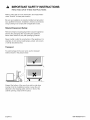 4
4
-
 5
5
-
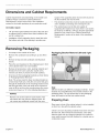 6
6
-
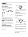 7
7
-
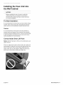 8
8
-
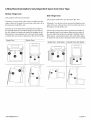 9
9
-
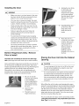 10
10
-
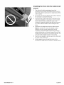 11
11
-
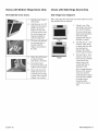 12
12
-
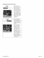 13
13
-
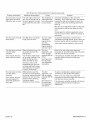 14
14
-
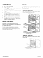 15
15
-
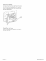 16
16
-
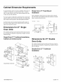 17
17
-
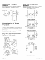 18
18
-
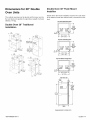 19
19
-
 20
20
-
 21
21
-
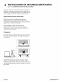 22
22
-
 23
23
-
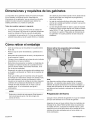 24
24
-
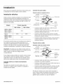 25
25
-
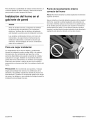 26
26
-
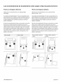 27
27
-
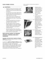 28
28
-
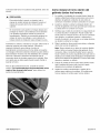 29
29
-
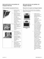 30
30
-
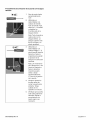 31
31
-
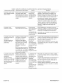 32
32
-
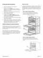 33
33
-
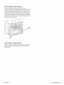 34
34
-
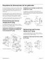 35
35
-
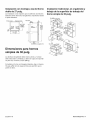 36
36
-
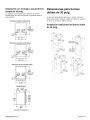 37
37
-
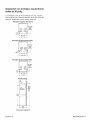 38
38
-
 39
39


Bosch HBL5351UC/02 Guía de instalación
- Categoría
- Hornos
- Tipo
- Guía de instalación