ESAB ESP-150 & PT-36R Direct Connect Manual de usuario
- Categoría
- Sistema de soldadura
- Tipo
- Manual de usuario

ESP-150 & PT-36R Direct Connect
Cut Data Manual
0558010719 03/2012

2
This equipment will perform in conformity with the description thereof contained in this manual and accompa-
nying labels and/or inserts when installed, operated, maintained and repaired in accordance with the instruc-
tions provided. This equipment must be checked periodically. Malfunctioning or poorly maintained equipment
should not be used. Parts that are broken, missing, worn, distorted or contaminated should be replaced imme-
diately. Should such repair or replacement become necessary, the manufacturer recommends that a telephone
or written request for service advice be made to the Authorized Distributor from whom it was purchased.
This equipment or any of its parts should not be altered without the prior written approval of the manufacturer.
The user of this equipment shall have the sole responsibility for any malfunction which results from improper
use, faulty maintenance, damage, improper repair or alteration by anyone other than the manufacturer or a ser-
vice facility designated by the manufacturer.
BE SURE THIS INFORMATION REACHES THE OPERATOR.
YOU CAN GET EXTRA COPIES THROUGH YOUR SUPPLIER.
These INSTRUCTIONS are for experienced operators. If you are not fully familiar with the
principles of operation and safe practices for arc welding and cutting equipment, we urge
you to read our booklet, “Precautions and Safe Practices for Arc Welding, Cutting, and
Gouging,” Form 52-529. Do NOT permit untrained persons to install, operate, or maintain
this equipment. Do NOT attempt to install or operate this equipment until you have read
and fully understand these instructions. If you do not fully understand these instructions,
contact your supplier for further information. Be sure to read the Safety Precautions be-
fore installing or operating this equipment.
CAUTION
USER RESPONSIBILITY
READ AND UNDERSTAND THE INSTRUCTION MANUAL BEFORE INSTALLING OR OPERATING.
PROTECT YOURSELF AND OTHERS!

3
TABLE OF CONTENTS
Section / Title Page
Safety Precautions. . . . . . . . . . . . . . . . . . . . . . . . . . . . . . . . . . . . . . . . . . . . . . . . . . . . . . . . . . . . . . . . . . . . . . . . . . . . . . . . . . . . . . . . . .5
1.1 Safety - English . . . . . . . . . . . . . . . . . . . . . . . . . . . . . . . . . . . . . . . . . . . . . . . . . . . . . . . . . . . . . . . . . . . . . . . . . . . . . . . . . . . .5
1.2 Safety - Spanish. . . . . . . . . . . . . . . . . . . . . . . . . . . . . . . . . . . . . . . . . . . . . . . . . . . . . . . . . . . . . . . . . . . . . . . . . . . . . . . . . . . .9
1.3 Safety - French. . . . . . . . . . . . . . . . . . . . . . . . . . . . . . . . . . . . . . . . . . . . . . . . . . . . . . . . . . . . . . . . . . . . . . . . . . . . . . . . . . . .13
2.1 PT-36R Direct Connect Gas Hose Connections . . . . . . . . . . . . . . . . . . . . . . . . . . . . . . . . . . . . . . . . . . . . . . . . . . . . . . . . . . .17
3.1 PT-36R Direct Connect Cut Data (INCH). . . . . . . . . . . . . . . . . . . . . . . . . . . . . . . . . . . . . . . . . . . . . . . . . . . . . . . . . . . . . . . . . .19
3.2 PT-36R Direct Connect Cut Data (METRIC) . . . . . . . . . . . . . . . . . . . . . . . . . . . . . . . . . . . . . . . . . . . . . . . . . . . . . . . . . . . . . . .31

4
TABLE OF CONTENTS

5
SECTION 1 SAFETY PRECAUTIONS
Safety Precautions
1.1 Safety - English
WARNING: These Safety Precautions are
for your protection. They summarize pre-
cautionary information from the references
listed in Additional Safety Information sec-
tion. Before performing any installation or operating
procedures, be sure to read and follow the safety precau-
tions listed below as well as all other manuals, material
safety data sheets, labels, etc. Failure to observe Safety
Precautions can result in injury or death.
PROTECT YOURSELF AND OTHERS --
Some welding, cutting, and gouging
processes are noisy and require ear
protection. The arc, like the sun, emits
ultraviolet (UV) and other radiation
and can injure skin and eyes. Hot metal can cause
burns. Training in the proper use of the processes
and equipment is essential to prevent accidents.
Therefore:
1. Always wear safety glasses with side shields in any
work area, even if welding helmets, face shields, and
goggles are also required.
2. Use a face shield tted with the correct lter and
cover plates to protect your eyes, face, neck, and
ears from sparks and rays of the arc when operating
or observing operations. Warn bystanders not to
watch the arc and not to expose themselves to the
rays of the electric-arc or hot metal.
3. Wear ameproof gauntlet type gloves, heavy long-
sleeve shirt, cuess trousers, high-topped shoes,
and a welding helmet or cap for hair protection, to
protect against arc rays and hot sparks or hot metal.
A ameproof apron may also be desirable as protec-
tion against radiated heat and sparks.
4. Hot sparks or metal can lodge in rolled up sleeves,
trouser cus, or pockets. Sleeves and collars should
be kept buttoned, and open pockets eliminated from
the front of clothing.
5. Protect other personnel from arc rays and hot
sparks with a suitable non-ammable partition or
curtains.
6. Use goggles over safety glasses when chipping slag
or grinding. Chipped slag may be hot and can y far.
Bystanders should also wear goggles over safety
glasses.
FIRES AND EXPLOSIONS -- Heat from
ames and arcs can start res. Hot
slag or sparks can also cause res and
explosions. Therefore:
1. Remove all combustible materials well away from
the work area or cover the materials with a protec-
tive non-ammable covering. Combustible materials
include wood, cloth, sawdust, liquid and gas fuels,
solvents, paints and coatings, paper, etc.
2. Hot sparks or hot metal can fall through cracks or
crevices in oors or wall openings and cause a hid-
den smoldering re or res on the oor below. Make
certain that such openings are protected from hot
sparks and metal.“
3. Do not weld, cut or perform other hot work until the
workpiece has been completely cleaned so that there
are no substances on the workpiece which might
produce ammable or toxic vapors. Do not do hot
work on closed containers. They may explode.
4. Have re extinguishing equipment handy for instant
use, such as a garden hose, water pail, sand bucket,
or portable re extinguisher. Be sure you are trained
in its use.
5. Do not use equipment beyond its ratings. For ex-
ample, overloaded welding cable can overheat and
create a re hazard.
6. After completing operations, inspect the work area
to make certain there are no hot sparks or hot metal
which could cause a later re. Use re watchers when
necessary.
7. For additional information, refer to NFPA Standard
51B, "Fire Prevention in Use of Cutting and Welding
Processes", available from the National Fire Protec-
tion Association, Batterymarch Park, Quincy, MA
02269.
ELECTRICAL SHOCK -- Contact with
live electrical parts and ground can
cause severe injury or death. DO NOT
use AC welding current in damp areas,
if movement is conned, or if there is
danger of falling.

6
SECTION 1 SAFETY PRECAUTIONS
1. Be sure the power source frame (chassis) is con-
nected to the ground system of the input power.
2. Connect the workpiece to a good electrical
ground.
3. Connect the work cable to the workpiece. A poor
or missing connection can expose you or others
to a fatal shock.
4. Use well-maintained equipment. Replace worn or
damaged cables.
5. Keep everything dry, including clothing, work
area, cables, torch/electrode holder, and power
source.
6. Make sure that all parts of your body are insulated
from work and from ground.
7. Do not stand directly on metal or the earth while
working in tight quarters or a damp area; stand
on dry boards or an insulating platform and wear
rubber-soled shoes.
8. Put on dry, hole-free gloves before turning on the
power.
9. Turn o the power before removing your gloves.
10. Refer to ANSI/ASC Standard Z49.1 (listed on
next page) for specic grounding recommenda-
tions. Do not mistake the work lead for a ground
cable.
ELECTRIC AND MAGNETIC FIELDS
— May be dangerous. Electric cur-
rent owing through any conduc-
tor causes localized Electric and
Magnetic Fields (EMF). Welding and
cutting current creates EMF around welding cables
and welding machines. Therefore:
1. Welders having pacemakers should consult their
physician before welding. EMF may interfere with
some pacemakers.
2. Exposure to EMF may have other health eects which
are unknown.
3. Welders should use the following procedures to
minimize exposure to EMF:
A. Route the electrode and work cables together.
Secure them with tape when possible.
B. Never coil the torch or work cable around your
body.
C. Do not place your body between the torch and
work cables. Route cables on the same side of
your body.
D. Connect the work cable to the workpiece as close
as possible to the area being welded.
E. Keep welding power source and cables as far
away from your body as possible.
FUMES AND GASES -- Fumes and
gases, can cause discomfort or harm,
particularly in conned spaces. Do
not breathe fumes and gases. Shield-
ing gases can cause asphyxiation.
Therefore:
1. Always provide adequate ventilation in the work area
by natural or mechanical means. Do not weld, cut, or
gouge on materials such as galvanized steel, stain-
less steel, copper, zinc, lead, beryllium, or cadmium
unless positive mechanical ventilation is provided.
Do not breathe fumes from these materials.
2. Do not operate near degreasing and spraying opera-
tions. The heat or arc rays can react with chlorinated
hydrocarbon vapors to form phosgene, a highly
toxic gas, and other irritant gases.
3. If you develop momentary eye, nose, or throat ir-
ritation while operating, this is an indication that
ventilation is not adequate. Stop work and take
necessary steps to improve ventilation in the work
area. Do not continue to operate if physical discom-
fort persists.
4. Refer to ANSI/ASC Standard Z49.1 (see listing below)
for specic ventilation recommendations.

7
SECTION 1 SAFETY PRECAUTIONS
5. WARNING: This product, when used for welding
or cutting, produces fumes or gases
which contain chemicals known to
the State of California to cause birth
defects and, in some cases, cancer.
(California Health & Safety Code
§25249.5 et seq.)
CYLINDER HANDLING -- Cylinders,
if mishandled, can rupture and vio-
lently release gas. Sudden rupture
of cylinder, valve, or relief device can
injure or kill. Therefore:
1. Use the proper gas for the process and use the
proper pressure reducing regulator designed to
operate from the compressed gas cylinder. Do not
use adaptors. Maintain hoses and ttings in good
condition. Follow manufacturer's operating instruc-
tions for mounting regulator to a compressed gas
cylinder.
2. Always secure cylinders in an upright position by
chain or strap to suitable hand trucks, undercar-
riages, benches, walls, post, or racks. Never secure
cylinders to work tables or xtures where they may
become part of an electrical circuit.
3. When not in use, keep cylinder valves closed. Have
valve protection cap in place if regulator is not con-
nected. Secure and move cylinders by using suitable
hand trucks. Avoid rough handling of cylinders.
4. Locate cylinders away from heat, sparks, and ames.
Never strike an arc on a cylinder.
5. For additional information, refer to CGA Standard P-1,
"Precautions for Safe Handling of Compressed Gases
in Cylinders", which is available from Compressed
Gas Association, 1235 Jeerson Davis Highway,
Arlington, VA 22202.
EQUIPMENT MAINTENANCE -- Faulty or
improperly maintained equipment can
cause injury or death. Therefore:
1. Always have qualied personnel perform the instal-
lation, troubleshooting, and maintenance work.
Do not perform any electrical work unless you are
qualied to perform such work.
2. Before performing any maintenance work inside a
power source, disconnect the power source from
the incoming electrical power.
3. Maintain cables, grounding wire, connections, power
cord, and power supply in safe working order. Do
not operate any equipment in faulty condition.
4. Do not abuse any equipment or accessories. Keep
equipment away from heat sources such as furnaces,
wet conditions such as water puddles, oil or grease,
corrosive atmospheres and inclement weather.
5. Keep all safety devices and cabinet covers in position
and in good repair.
6. Use equipment only for its intended purpose. Do
not modify it in any manner.
ADDITIONAL SAFETY INFORMATION -- For
more information on safe practices for
electric arc welding and cutting equip-
ment, ask your supplier for a copy of
"Precautions and Safe Practices for Arc
Welding, Cutting and Gouging", Form
52-529.
The following publications, which are available from
the American Welding Society, 550 N.W. LeJuene Road,
Miami, FL 33126, are recommended to you:
1. ANSI/ASC Z49.1 - "Safety in Welding and Cutting"
2. AWS C5.1 - "Recommended Practices for Plasma Arc
Welding"
3. AWS C5.2 - "Recommended Practices for Plasma Arc
Cutting"
4. AWS C5.3 - "Recommended Practices for Air Carbon
Arc Gouging and Cutting"

8
SECTION 1 SAFETY PRECAUTIONS
5. AWS C5.5 - "Recommended Practices for Gas Tung-
sten Arc Welding“
6. AWS C5.6 - "Recommended Practices for Gas Metal
Arc Welding"“
7. AWS SP - "Safe Practices" - Reprint, Welding Hand-
book.
8. ANSI/AWS F4.1, "Recommended Safe Practices for
Welding and Cutting of Containers That Have Held
Hazardous Substances."
MEANING OF SYMBOLS - As used
throughout this manual: Means Atten-
tion! Be Alert! Your safety is involved.
Means immediate hazards which,
if not avoided, will result in im-
mediate, serious personal injury
or loss of life.
Means potential hazards which
could result in personal injury or
loss of life.
Means hazards which could result
in minor personal injury.

9
SECTION 1 SEGURIDAD
1.2 Safety - Spanish
ADVERTENCIA: Estas Precauciones de Se-
guridad son para su protección. Ellas hacen
resumen de información proveniente de las
referencias listadas en la sección "Información Adi-
cional Sobre La Seguridad". Antes de hacer cualquier
instalación o procedimiento de operación , asegúrese
de leer y seguir las precauciones de seguridad listadas
a continuación así como también todo manual, hoja
de datos de seguridad del material, calcomanias, etc.
El no observar las Precauciones de Seguridad puede
resultar en daño a la persona o muerte.
PROTEJASE USTED Y A LOS DEMAS--
Algunos procesos de soldadura, corte
y ranurado son ruidosos y requiren
protección para los oídos. El arco,
como el sol , emite rayos ultravioleta
(UV) y otras radiaciones que pueden dañar la piel
y los ojos. El metal caliente causa quemaduras. EL
entrenamiento en el uso propio de los equipos y
sus procesos es esencial para prevenir accidentes.
Por lo tanto:
1. Utilice gafas de seguridad con protección a los lados
siempre que esté en el área de trabajo, aún cuando
esté usando careta de soldar, protector para su cara
u otro tipo de protección.
2. Use una careta que tenga el ltro correcto y lente
para proteger sus ojos, cara, cuello, y oídos de las
chispas y rayos del arco cuando se esté operando y
observando las operaciones. Alerte a todas las per-
sonas cercanas de no mirar el arco y no exponerse
a los rayos del arco eléctrico o el metal fundido.
3. Use guantes de cuero a prueba de fuego, camisa
pesada de mangas largas, pantalón de ruedo liso,
zapato alto al tobillo, y careta de soldar con capucha
para el pelo, para proteger el cuerpo de los rayos y
chispas calientes provenientes del metal fundido.
En ocaciones un delantal a prueba de fuego es
necesario para protegerse del calor radiado y las
chispas.
4. Chispas y partículas de metal caliente puede alojarse
en las mangas enrolladas de la camisa , el ruedo del
pantalón o los bolsillos. Mangas y cuellos deberán
mantenerse abotonados, bolsillos al frente de la
camisa deberán ser cerrados o eliminados.
5. Proteja a otras personas de los rayos del arco y chis-
pas calientes con una cortina adecuada no-amable
como división.
6. Use careta protectora además de sus gafas de segu-
ridad cuando esté removiendo escoria o puliendo.
La escoria puede estar caliente y desprenderse con
velocidad. Personas cercanas deberán usar gafas
de seguridad y careta protectora.
FUEGO Y EXPLOSIONES -- El calor de
las amas y el arco pueden ocacionar
fuegos. Escoria caliente y las chispas
pueden causar fuegos y explosiones.
Por lo tanto:
1. Remueva todo material combustible lejos del área
de trabajo o cubra los materiales con una cobija a
prueba de fuego. Materiales combustibles incluyen
madera, ropa, líquidos y gases amables, solventes,
pinturas, papel, etc.
2. Chispas y partículas de metal pueden introducirse en
las grietas y agujeros de pisos y paredes causando
fuegos escondidos en otros niveles o espacios.
Asegúrese de que toda grieta y agujero esté cubierto
para proteger lugares adyacentes contra fuegos.
3. No corte, suelde o haga cualquier otro trabajo
relacionado hasta que la pieza de trabajo esté to-
talmente limpia y libre de substancias que puedan
producir gases inamables o vapores tóxicos. No
trabaje dentro o fuera de contenedores o tanques
cerrados. Estos pueden explotar si contienen vapores
inamables.
4. Tenga siempre a la mano equipo extintor de fu-
ego para uso instantáneo, como por ejemplo una
manguera con agua, cubeta con agua, cubeta con
arena, o extintor portátil. Asegúrese que usted esta
entrenado para su uso.
5. No use el equipo fuera de su rango de operación. Por
ejemplo, el calor causado por cable sobrecarga en
los cables de soldar pueden ocasionar un fuego.
6. Después de termirar la operación del equipo, inspec-
cione el área de trabajo para cerciorarse de que las
chispas o metal caliente ocasionen un fuego más
tarde. Tenga personal asignado para vigilar si es
necesario.
7. Para información adicional , haga referencia a la
publicación NFPA Standard 51B, "Fire Prevention in
Use of Cutting and Welding Processes", disponible
a través de la National Fire Protection Association,
Batterymarch Park, Quincy, MA 02269.
CHOQUE ELECTRICO -- El contacto
con las partes eléctricas energizadas
y tierra puede causar daño severo o
muerte. NO use soldadura de corri-
ente alterna (AC) en áreas húmedas,
de movimiento connado en lugares estrechos o
si hay posibilidad de caer al suelo.

10
SECTION 1 SEGURIDAD
1. Asegúrese de que el chasis de la fuente de poder
esté conectado a tierra através del sistema de
electricidad primario.
2. Conecte la pieza de trabajo a un buen sistema de
tierra física.
3. Conecte el cable de retorno a la pieza de trabajo.
Cables y conductores expuestos o con malas
conexiones pueden exponer al operador u otras
personas a un choque eléctrico fatal.
4. Use el equipo solamente si está en buenas condi-
ciones. Reemplaze cables rotos, dañados o con
conductores expuestos.
5. Mantenga todo seco, incluyendo su ropa, el área de
trabajo, los cables, antorchas, pinza del electrodo,
y la fuente de poder.
6. Asegúrese que todas las partes de su cuerpo están
insuladas de ambos, la pieza de trabajo y tierra.
7. No se pare directamente sobre metal o tierra mien-
tras trabaja en lugares estrechos o áreas húmedas;
trabaje sobre un pedazo de madera seco o una
plataforma insulada y use zapatos con suela de
goma.
8. Use guantes secos y sin agujeros antes de energizar
el equipo.
9. Apage el equipo antes de quitarse sus guantes.
10. Use como referencia la publicación ANSI/ASC
Standard Z49.1 (listado en la próxima página) para
recomendaciones especícas de como conectar el
equipo a tierra. No confunda el cable de soldar a
la pieza de trabajo con el cable a tierra.
CAMPOS ELECTRICOS Y MAGNETI-
COS - Son peligrosos. La corriente
eléctrica uye através de cualquier
conductor causando a nivel local
Campos Eléctricos y Magnéticos
(EMF). Las corrientes en el área de corte y soldadura,
crean EMF alrrededor de los cables de soldar y las
maquinas. Por lo tanto:
1. Soldadores u Operadores que use marca-pasos para
el corazón deberán consultar a su médico antes de
soldar. El Campo Electromagnético (EMF) puede
interferir con algunos marca-pasos.
2. Exponerse a campos electromagnéticos (EMF) puede
causar otros efectos de salud aún desconocidos.
3. Los soldadores deberán usar los siguientes proced-
imientos para minimizar exponerse al EMF:
A. Mantenga el electrodo y el cable a la pieza de
trabajo juntos, hasta llegar a la pieza que usted
quiere soldar. Asegúrelos uno junto al otro con
cinta adhesiva cuando sea posible.
B. Nunca envuelva los cables de soldar alrededor
de su cuerpo.
C. Nunca ubique su cuerpo entre la antorcha y el
cable, a la pieza de trabajo. Mantega los cables a
un sólo lado de su cuerpo.
D. Conecte el cable de trabajo a la pieza de trabajo
lo más cercano posible al área de la soldadura.
E. Mantenga la fuente de poder y los cables de soldar
lo más lejos posible de su cuerpo.
HUMO Y GASES -- El humo y los
gases, pueden causar malestar o
daño, particularmente en espacios
sin ventilación. No inhale el humo
o gases. El gas de protección puede
causar falta de oxígeno.
Por lo tanto:
1. Siempre provea ventilación adecuada en el área
de trabajo por medio natural o mecánico. No solde,
corte, o ranure materiales con hierro galvanizado,
acero inoxidable, cobre, zinc, plomo, berílio, o cad-
mio a menos que provea ventilación mecánica
positiva . No respire los gases producidos por
estos materiales.
2. No opere cerca de lugares donde se aplique sub-
stancias químicas en aerosol. El calor de los rayos
del arco pueden reaccionar con los vapores de
hidrocarburo clorinado para formar un fosfógeno,
o gas tóxico, y otros irritant es.
3. Si momentáneamente desarrolla inrritación de
ojos, nariz o garganta mientras est á operando, es
indicación de que la ventilación no es apropiada.
Pare de trabajar y tome las medidas necesarias
para mejorar la ventilación en el área de trabajo.
No continúe operando si el malestar físico per-
siste.
4. Haga referencia a la publicación ANSI/ASC Standard
Z49.1 (Vea la lista a continuación) para recomen-
daciones especícas en la ventilación.

11
SECTION 1 SEGURIDAD
5. ADVERTENCIA-- Este producto cuando se uti-
liza para soldaduras o cortes,
produce humos o gases, los
cuales contienen químicos
conocidos por el Estado de Cali-
fornia de causar defectos en el
nacimiento, o en algunos casos,
Cancer. (California Health &
Safety Code §25249.5 et seq.)
MANEJO DE CILINDROS-- Los
cilindros, si no son manejados
correctamente, pueden romp-
erse y liberar violentamente
gases. Rotura repentina del
cilindro, válvula, o válvula de
escape puede causar daño o
muerte. Por lo tanto:
1. Utilize el gas apropiado para el proceso y utilize
un regulador diseñado para operar y reducir la
presión del cilindro de gas . No utilice adapta-
dores. Mantenga las mangueras y las conexiones
en buenas condiciones. Observe las instrucciones
de operación del manufacturero para montar el
regulador en el cilindro de gas comprimido.
2. Asegure siempre los cilindros en posición vertical
y amárrelos con una correa o cadena adecuada
para asegurar el cilindro al carro, transportes, tablil-
leros, paredes, postes, o armazón. Nunca asegure
los cilindros a la mesa de trabajo o las piezas que
son parte del circuito de soldadura . Este puede ser
parte del circuito elélectrico.
3. Cuando el cilindro no está en uso, mantenga la
válvula del cilindro cerrada. Ponga el capote de
protección sobre la válvula si el regulador no
está conectado. Asegure y mueva los cilindros
utilizando un carro o transporte adecuado. Evite
el manejo brusco de los
MANTENIMIENTO DEL EQUIPO -- Equipo
defectuoso o mal mantenido puede
causar daño o muerte. Por lo tanto:
1. Siempre tenga personal cualicado para efec-
tuar l a instalación, diagnóstico, y mantenimiento
del equipo. No ejecute ningún trabajo eléctrico a
menos que usted esté cualicado para hacer el
trabajo.
2. Antes de dar mantenimiento en el interior de la
fuente de poder, desconecte la fuente de poder
del suministro de electricidad primaria.
3. Mantenga los cables, cable a tierra, conexciones,
cable primario, y cualquier otra fuente de poder
en buen estado operacional. No opere ningún
equipo en malas condiciones.
4. No abuse del equipo y sus accesorios. Mantenga
el equipo lejos de cosas que generen calor como
hornos, también lugares húmedos como charcos
de agua , aceite o grasa, atmósferas corrosivas y
las inclemencias del tiempo.
5. Mantenga todos los artículos de seguridad y
coverturas del equipo en su posición y en buenas
condiciones.
6. Use el equipo sólo para el propósito que fue
diseñado. No modique el equipo en ninguna
manera.
INFORMACION ADICIONAL DE SEGURI-
DAD -- Para más información sobre las
prácticas de seguridad de los equipos de
arco eléctrico para soldar y cortar, pregunte
a su suplidor por una copia de "Precautions
and Safe Practices for Arc Welding, Cutting
and Gouging-Form 52-529.
Las siguientes publicaciones, disponibles através de
la American Welding Society, 550 N.W. LeJuene Road,
Miami, FL 33126, son recomendadas para usted:
1. ANSI/ASC Z49.1 - "Safety in Welding and Cutting"
2. AWS C5.1 - "Recommended Practices for Plasma Arc
Welding"
3. AWS C5.2 - "Recommended Practices for Plasma Arc
Cutting"
4. AWS C5.3 - "Recommended Practices for Air Carbon
Arc Gouging and Cutting"

12
SECTION 1 SEGURIDAD
SIGNIFICADO DE LOS SIMBOLOS
-- Según usted avanza en la lectura
de este folleto: Los Símbolos Sig-
nican ¡Atención! ¡Esté Alerta! Se
trata de su seguridad.
Signica riesgo inmediato que,
de no ser evadido, puede resultar
inmediatamente en serio daño
personal o la muerte.
Signica el riesgo de un peligro
potencial que puede resultar en
serio daño personal o la muerte.
Signica el posible riesgo que
puede resultar en menores daños
a la persona.

13
SECTION 1 SÉCURITÉ
1.3 Safety - French
INCENDIES ET EXPLOSIONS -- La chal-
eur provenant des ammes ou de
l'arc peut provoquer un incendie. Le
laitier incandescent ou les étincelles
peuvent également provoquer un
incendie ou une explosion. Par conséquent :
1. Éloignez susamment tous les matériaux combustibles
de l'aire de travail et recouvrez les matériaux avec un
revêtement protecteur ininammable. Les matériaux
combustibles incluent le bois, les vêtements, la sciure, le
gaz et les liquides combustibles, les solvants, les peintures
et les revêtements, le papier, etc.
2. Les étincelles et les projections de métal incandescent
peuvent tomber dans les ssures dans les planchers ou
dans les ouvertures des murs et déclencher un incendie
couvant à l'étage inférieur Assurez-vous que ces ouver-
tures sont bien protégées des étincelles et du métal
incandescent.
3. N'exécutez pas de soudure, de coupe ou autre travail à
chaud avant d'avoir complètement nettoyé la surface de
la pièce à traiter de façon à ce qu'il n'ait aucune substance
présente qui pourrait produire des vapeurs inammables
ou toxiques. N'exécutez pas de travail à chaud sur des
contenants fermés car ces derniers pourraient exploser.
4. Assurez-vous qu'un équipement d'extinction d'incendie
est disponible et prêt à servir, tel qu'un tuyau d'arrosage,
un seau d'eau, un seau de sable ou un extincteur portatif.
Assurez-vous d'être bien instruit par rapport à l'usage de
cet équipement.
5. Assurez-vous de ne pas excéder la capacité de
l'équipement. Par exemple, un câble de soudage sur-
chargé peut surchauer et provoquer un incendie.
6. Une fois les opérations terminées, inspectez l'aire de
travail pour assurer qu'aucune étincelle ou projection de
métal incandescent ne risque de provoquer un incendie
ultérieurement. Employez des guetteurs d'incendie au
besoin.
7. Pour obtenir des informations supplémentaires, con-
sultez le NFPA Standard 51B, "Fire Prevention in Use of
Cutting and Welding Processes", disponible au National
Fire Protection Association, Batterymarch Park, Quincy,
MA 02269.
CHOC ÉLECTRIQUE -- Le contact avec des pièces
électriques ou les pièces de mise à la terre sous
tension peut causer des blessures
graves ou mortelles. NE PAS utiliser
un courant de soudage c.a. dans un
endroit humide, en espace restreint
ou si un danger de chute se pose.
AVERTISSEMENT : Ces règles de sécurité
ont pour but d'assurer votre protection. Ils
récapitulent les informations de précaution
provenant des références dans la section
des Informations de sécurité supplémentaires. Avant
de procéder à l'installation ou d'utiliser l'unité, assurez-
vous de lire et de suivre les précautions de sécurité ci-
dessous, dans les manuels, les ches d'information sur la
sécurité du matériel et sur les étiquettes, etc. Tout défaut
d'observer ces précautions de sécurité peut entraîner
des blessures graves ou mortelles.
PROTÉGEZ-VOUS -- Les processus de
soudage, de coupage et de gougeage
produisent un niveau de bruit élevé et
exige l'emploi d'une protection auditive. L'arc, tout
comme le soleil, émet des rayons ultraviolets en plus
d'autre rayons qui peuvent causer des blessures à la
peau et les yeux. Le métal incandescent peut causer
des brûlures. Une formation reliée à l'usage des
processus et de l'équipement est essentielle pour
prévenir les accidents. Par conséquent:
1. Portez des lunettes protectrices munies d'écrans latéraux
lorsque vous êtes dans l'aire de travail, même si vous de-
vez porter un casque de soudeur, un écran facial ou des
lunettes étanches.
2. Portez un écran facial muni de verres ltrants et de plaques
protectrices appropriées an de protéger vos yeux, votre
visage, votre cou et vos oreilles des étincelles et des rayons
de l'arc lors d'une opération ou lorsque vous observez une
opération. Avertissez les personnes se trouvant à proximité
de ne pas regarder l'arc et de ne pas s'exposer aux rayons
de l'arc électrique ou le métal incandescent.
3. Portez des gants ignifugiés à crispin, une chemise épaisse
à manches longues, des pantalons sans rebord et des
chaussures montantes an de vous protéger des rayons
de l'arc, des étincelles et du métal incandescent, en plus
d'un casque de soudeur ou casquette pour protéger vos
cheveux. Il est également recommandé de porter un tablier
ininammable an de vous protéger des étincelles et de
la chaleur par rayonnement.
4. Les étincelles et les projections de métal incandescent
risquent de se loger dans les manches retroussées, les
rebords de pantalons ou les poches. Il est recommandé
de garder boutonnés le col et les manches et de porter
des vêtements sans poches en avant.
5. Protégez toute personne se trouvant à proximité des étin-
celles et des rayons de l'arc à l'aide d'un rideau ou d'une
cloison ininammable.
6. Portez des lunettes étanches par dessus vos lunettes de
sécurité lors des opérations d'écaillage ou de meulage
du laitier. Les écailles de laitier incandescent peuvent être
projetées à des distances considérables. Les personnes se
trouvant à proximité doivent également porter des lunettes
étanches par dessus leur lunettes de sécurité.

14
SECTION 1 SÉCURITÉ
3. Les soudeurs doivent suivre les procédures suivantes
pour minimiser l'exposition aux champs électriques
et magnétiques :
A. Acheminez l'électrode et les câbles de masse
ensemble. Fixez-les à l'aide d'une bande adhésive
lorsque possible.
B. Ne jamais enrouler la torche ou le câble de masse
autour de votre corps.
C. Ne jamais vous placer entre la torche et les câbles
de masse. Acheminez tous les câbles sur le même
côté de votre corps.
D. Branchez le câble de masse à la pièce à traiter le
plus près possible de la section à souder.
E. Veillez à garder la source d'alimentation pour le
soudage et les câbles à une distance appropriée
de votre corps.
LES VAPEURS ET LES GAZ -- peuvent
causer un malaise ou des dommages
corporels, plus particulièrement
dans les espaces restreints. Ne re-
spirez pas les vapeurs et les gaz. Le
gaz de protection risque de causer
l'asphyxie. Par conséquent :
1. Assurez en permanence une ventilation adéquate
dans l'aire de travail en maintenant une ventila-
tion naturelle ou à l'aide de moyens mécanique.
N'effectuez jamais de travaux de soudage, de
coupage ou de gougeage sur des matériaux tels que
l'acier galvanisé, l'acier inoxydable, le cuivre, le zinc,
le plomb, le berylliym ou le cadmium en l'absence
de moyens mécaniques de ventilation ecaces. Ne
respirez pas les vapeurs de ces matériaux.
2. N'eectuez jamais de travaux à proximité d'une
opération de dégraissage ou de pulvérisation. Lor-
sque la chaleur
ou le rayonnement de l'arc entre en contact avec les
vapeurs d'hydrocarbure chloré, ceci peut déclencher
la formation de phosgène ou d'autres gaz irritants,
tous extrêmement toxiques.
3. Une irritation momentanée des yeux, du nez ou de la
gorge au cours d'une opération indique que la ven-
tilation n'est pas adéquate. Cessez votre travail an
de prendre les mesures nécessaires pour améliorer
la ventilation dans l'aire de travail. Ne poursuivez
pas l'opération si le malaise persiste.
4. Consultez ANSI/ASC Standard Z49.1 (à la page
suivante) pour des recommandations spéciques
concernant la ventilation.
1. Assurez-vous que le châssis de la source
d'alimentation est branché au système de mise à
la terre de l'alimentation d'entrée.
2. Branchez la pièce à traiter à une bonne mise de
terre électrique.
3. Branchez le câble de masse à la pièce à traiter et
assurez une bonne connexion an d'éviter le risque
de choc électrique mortel.
4. Utilisez toujours un équipement correctement
entretenu. Remplacez les câbles usés ou endom-
magés.
5. Veillez à garder votre environnement sec, incluant
les vêtements, l'aire de travail, les câbles, le porte-
électrode/torche et la source d'alimentation.
6. Assurez-vous que tout votre corps est bien isolé
de la pièce à traiter et des pièces de la mise à la
terre.
7. Si vous devez eectuer votre travail dans un espace
restreint ou humide, ne tenez vous pas directe-
ment sur le métal ou sur la terre; tenez-vous sur
des planches sèches ou une plate-forme isolée et
portez des chaussures à semelles de caoutchouc.
8. Avant de mettre l'équipement sous tension, isolez
vos mains avec des gants secs et sans trous.
9. Mettez l'équipement hors tension avant d'enlever
vos gants.
10. Consultez ANSI/ASC Standard Z49.1 (listé à
la page suivante) pour des recommandations
spéciques concernant les procédures de mise à
la terre. Ne pas confondre le câble de masse avec
le câble de mise à la terre.
CHAMPS ÉLECTRIQUES ET MAGNÉ-
TIQUES — comportent un risque de
danger. Le courant électrique qui
passe dans n'importe quel conduc-
teur produit des champs électriques
et magnétiques localisés. Le soudage et le cou-
rant de coupage créent des champs électriques
et magnétiques autour des câbles de soudage et
l'équipement. Par conséquent :
1. Un soudeur ayant un stimulateur cardiaque doit
consulter son médecin avant d'entreprendre une
opération de soudage. Les champs électriques et
magnétiques peuvent causer des ennuis pour cer-
tains stimulateurs cardiaques.
2. L'exposition à des champs électriques et magné-
tiques peut avoir des eets néfastes inconnus pour
la santé.

15
SECTION 1 SÉCURITÉ
1. Efforcez-vous de toujours confier les tâches
d'installation, de dépannage et d'entretien à un
personnel qualié. N'eectuez aucune réparation
électrique à moins d'être qualié à cet eet.
2. Avant de procéder à une tâche d'entretien à
l'intérieur de la source d'alimentation, débranchez
l'alimentation électrique.
3. Maintenez les câbles, les ls de mise à la terre,
les branchements, le cordon d'alimentation et la
source d'alimentation en bon état. N'utilisez ja-
mais un équipement s'il présente une défectuosité
quelconque.
4. N'utilisez pas l'équipement de façon abusive. Gardez
l'équipement à l'écart de toute source de chaleur,
notamment des fours, de l'humidité, des aques
d'eau, de l'huile ou de la graisse, des atmosphères
corrosives et des intempéries.
5. Laissez en place tous les dispositifs de sécurité et
tous les panneaux de la console et maintenez-les
en bon état.
6. Utilisez l'équipement conformément à son usage
prévu et n'eectuez aucune modication.
INFORMATIONS SUPPLÉMENTAIRES RELA-
TIVES À LA SÉCURITÉ -- Pour obtenir de
l'information supplémentaire sur les règles
de sécurité à observer pour l'équipement
de soudage à l'arc électrique et le coupage,
demandez un exemplaire du livret "Precau-
tions and Safe Practices for Arc Welding,
Cutting and Gouging", Form 52-529.
Les publications suivantes sont également recomman-
dées et mises à votre disposition par l'American Welding
Society, 550 N.W. LeJuene Road, Miami, FL 33126 :
1. ANSI/ASC Z49.1 - "Safety in Welding and Cutting"
2. AWS C5.1 - "Recommended Practices for Plasma Arc
Welding"
3. AWS C5.2 - "Recommended Practices for Plasma Arc
Cutting"
4. AWS C5.3 - "Recommended Practices for Air Carbon
Arc Gouging and Cutting"
5. AVERTISSEMENT : Ce produit, lorsqu'il est utilisé
dans une opération de soudage ou de
coupage, dégage des vapeurs ou des
gaz contenant des chimiques consid-
éres par l'état de la Californie comme
étant une cause des malformations
congénitales et dans certains cas, du
cancer. (California Health & Safety
Code §25249.5 et seq.)
MANIPULATION DES CYLINDRES --
La manipulation d'un cylindre, sans
observer les précautions nécessaires,
peut produire des fissures et un
échappement dangereux des gaz.
Une brisure soudaine du cylindre, de la soupape ou
du dispositif de surpression peut causer des bles-
sures graves ou mortelles. Par conséquent :
1. Utilisez toujours le gaz prévu pour une opération
et le détendeur approprié conçu pour utilisation
sur les cylindres de gaz comprimé. N'utilisez jamais
d'adaptateur. Maintenez en bon état les tuyaux et
les raccords. Observez les instructions d'opération
du fabricant pour assembler le détendeur sur un
cylindre de gaz comprimé.
2. Fixez les cylindres dans une position verticale, à
l'aide d'une chaîne ou une sangle, sur un chariot
manuel, un châssis de roulement, un banc, un mur,
une colonne ou un support convenable. Ne xez
jamais un cylindre à un poste de travail ou toute autre
dispositif faisant partie d'un circuit électrique.
3. Lorsque les cylindres ne servent pas, gardez les
soupapes fermées. Si le détendeur n'est pas bran-
ché, assurez-vous que le bouchon de protection de
la soupape est bien en place. Fixez et déplacez les
cylindres à l'aide d'un chariot manuel approprié.
Toujours manipuler les cylindres avec soin.
4. Placez les cylindres à une distance appropriée
de toute source de chaleur, des étincelles et des
ammes. Ne jamais amorcer l'arc sur un cylindre.
5. Pour de l'information supplémentaire, consultez
CGA Standard P-1, "Precautions for Safe Handling
of Compressed Gases in Cylinders", mis à votre dis-
position par le Compressed Gas Association, 1235
Jeerson Davis Highway, Arlington, VA 22202.
ENTRETIEN DE L'ÉQUIPEMENT -- Un équipe-
ment entretenu de façon défectueuse ou
inadéquate peut causer des blessures
graves ou mortelles. Par conséquent :

16
SECTION 1 SÉCURITÉ
SIGNIFICATION DES SYMBOLES
Ce symbole, utilisé partout dans ce manuel,
signie "Attention" ! Soyez vigilant ! Votre
sécurité est en jeu.
Signie un danger immédiat. La situation peut
entraîner des blessures graves ou mortelles.
Signie un danger potentiel qui peut entraîner des
blessures graves ou mortelles.
Signie un danger qui peut entraîner des blessures
corporelles mineures.
DANGER
AVERTISSEMENT
ATTENTION

17
2.1 PT-36R Direct Connect Gas Hose Connections
1 - Shield gas connection - Female 5/8-18 RH (right-hand threaded).
2 - Water-cooled power cables -
2a - Male 7/8-14 LH (left-hand threaded).
2b - Male 5/8-18 LH (left-hand threaded).
3 - Pilot Arc Cable - connected to the arc starter box.
4 - Plasma gas connection - Male 5/8-18 RH B-IG (right-hand threaded "B" Inert Gas).
SECTION 2 INSTALLATION
Pilot Arc Cable Adaptor
p/n 0558009992
(hardware supplied)
Brass Nut (951188) from torch leads
attaches to Brass Strain relief (33053)
1
Pilot Arc Cable
2a
Shield Gas Hose
3
4
Plasma Gas Hose
2b
Power Cables

18
SECTION 2 INSTALLATION
PT-36 Torch Dimensions:
2.00"
(50.8mm)
7.54"
(191.5mm)
6.17"
(156.7mm)
10.50" (266.7mm)
Length of Sleeve
9.13"
(231.9mm)
NOTE:
Clamp only on insulated torch sleeve not less than
1.25" (31.7mm) from the torch end of sleeve.

19
3.1 PT-36R Direct Connect Cut Data (INCH)
SECTION 3 CUT DATA
PT-36R
Direct Connect
Inch Cut Data

20

21
ESAB Welding and Cutting Products
PRODUCTION
Gas Select 8
Material Aluminium
Amperes 55
Start Gas AIR
Cut Gas AIR
Shield Gas-1 AIR
Shield Gas-2 NONE
0.100 130 0.045 155 0.160 0.120 0.120 0.1 0.5 0 0 50 58 65 65 0 0
0.125 110 0.045 160 0.160 0.120 0.120 0.1 0.5 0 0 50 58 65 65 0 0
0.160 95 0.045 160 0.160 0.120 0.120 0.1 0.5 0 0 50 58 65 65 0 0
0.200 80 0.045 160 0.160 0.120 0.120 0.1 0.5 0 0 50 58 65 65 0 0
0.250 70 0.045 160 0.160 0.120 0.120 0.1 0.5 0 0 50 58 65 65 0 0
PicNo
1
Thick-
ness
in
Speed
in/m
Kerf
in
Arc
Volt-
age
Initial
Height
in
Pierce
Height
in
Cut-
ting
Height
in
Pierce
Delay
sec
AHC
Delay
sec
Plasma Gas PG-1 Plasma Gas PG-2 Shield Gas SG-1 Shield Gas SG-2
Start
psi
Cut
psi
Start
psi
Cut
psi
Start
psi
Cut
psi
Start
CFH
Cut
CFH

22
ESAB Welding and Cutting Products
PRODUCTION
Gas Select 8
Material Aluminium
Amperes 100
Start Gas AIR
Cut Gas AIR
Shield Gas-1 AIR
Shield Gas-2 NONE
0.200 120 0.095 151 0.160 0.375 0.187 0.1 0.5 0 0 29 45 65 65 0 0
0.250 100 0.100 154 0.160 0.375 0.187 0.4 0.5 0 0 29 45 65 65 0 0
0.375 70 0.110 174 0.160 0.375 0.250 0.6 0.8 0 0 29 45 85 85 0 0
0.500 50 0.110 183 0.160 0.375 0.312 0.6 0.8 0 0 29 45 85 85 0 0
0.625 40 0.112 186 0.160 0.500 0.312 0.6 0.9 0 0 29 45 85 85 0 0
0.750 30 0.115 189 0.160 0.500 0.312 0.7 0.9 0 0 29 45 65 65 0 0
PicNo
21
Thick-
ness
in
Speed
in/m
Kerf
in
Arc
Volt-
age
Initial
Height
in
Pierce
Height
in
Cut-
ting
Height
in
Pierce
Delay
sec
AHC
Delay
sec
Plasma Gas PG-1 Plasma Gas PG-2 Shield Gas SG-1 Shield Gas SG-2
Start
psi
Cut
psi
Start
psi
Cut
psi
Start
psi
Cut
psi
Start
CFH
Cut
CFH

23
ESAB Welding and Cutting Products
PRODUCTION
Gas Select 8
Material Aluminium
Amperes 150
Start Gas AIR
Cut Gas AIR
Shield Gas-1 AIR
Shield Gas-2 NONE
0.200 200 0.110 148 0.160 0.375 0.187 0.2 0.4 0 0 29 40 85 85 0 0
0.250 140 0.110 149 0.160 0.375 0.187 0.2 0.4 0 0 29 40 85 85 0 0
0.375 105 0.130 159 0.160 0.375 0.250 0.2 0.4 0 0 29 40 65 65 0 0
0.500 80 0.140 174 0.160 0.375 0.312 0.3 0.5 0 0 29 40 85 85 0 0
0.625 65 0.140 177 0.160 0.500 0.312 0.6 0.5 0 0 29 40 85 85 0 0
0.750 45 0.140 180 0.160 0.500 0.312 0.5 0.5 0 0 29 40 65 65 0 0
1.000 30 0.150 184 0.160 0.500 0.312 0.7 0.5 0 0 29 40 65 65 0 0
PicNo
22
Thick-
ness
in
Speed
in/m
Kerf
in
Arc
Volt-
age
Initial
Height
in
Pierce
Height
in
Cut-
ting
Height
in
Pierce
Delay
sec
AHC
Delay
sec
Plasma Gas PG-1 Plasma Gas PG-2 Shield Gas SG-1 Shield Gas SG-2
Start
psi
Cut
psi
Start
psi
Cut
psi
Start
psi
Cut
psi
Start
CFH
Cut
CFH

24
ESAB Welding and Cutting Products
PRODUCTION
Gas Select 8
Material Carbon Steel
Amperes 55
Start Gas AIR
Cut Gas AIR
Shield Gas-1 AIR
Shield Gas-2 NONE
0.100 220 0.040 140 0.160 0.160 0.120 0.1 0.5 0 0 50 58 65 65 0 0
0.125 180 0.045 145 0.160 0.160 0.120 0.1 0.5 0 0 50 58 65 65 0 0
0.160 137 0.045 150 0.160 0.160 0.120 0.1 0.5 0 0 50 58 65 65 0 0
0.200 95 0.045 150 0.160 0.160 0.120 0.1 0.5 0 0 50 58 65 65 0 0
0.250 80 0.045 155 0.160 0.160 0.120 0.1 0.5 0 0 50 58 65 65 0 0
PicNo
1
Thick-
ness
in
Speed
in/m
Kerf
in
Arc
Volt-
age
Initial
Height
in
Pierce
Height
in
Cut-
ting
Height
in
Pierce
Delay
sec
AHC
Delay
sec
Plasma Gas PG-1 Plasma Gas PG-2 Shield Gas SG-1 Shield Gas SG-2
Start
psi
Cut
psi
Start
psi
Cut
psi
Start
psi
Cut
psi
Start
CFH
Cut
CFH

25
ESAB Welding and Cutting Products
PRODUCTION
Gas Select 8
Material Carbon Steel
Amperes 100
Start Gas AIR
Cut Gas AIR
Shield Gas-1 AIR
Shield Gas-2 NONE
0.200 150 0.118 148 0.160 0.375 0.125 0.3 0.5 0 0 29 45 110 110 0 0
0.250 120 0.122 154 0.160 0.375 0.156 0.4 0.5 0 0 29 45 85 85 0 0
0.375 65 0.126 162 0.160 0.375 0.187 0.4 0.5 0 0 29 45 85 85 0 0
0.500 50 0.130 162 0.160 0.375 0.187 0.5 0.5 0 0 29 45 65 65 0 0
0.625 35 0.142 175 0.160 0.500 0.281 0.6 0.5 0 0 29 45 65 65 0 0
0.750 20 0.146 184 0.160 0.500 0.312 0.7 0.5 0 0 29 45 65 65 0 0
PicNo
21
Thick-
ness
in
Speed
in/m
Kerf
in
Arc
Volt-
age
Initial
Height
in
Pierce
Height
in
Cut-
ting
Height
in
Pierce
Delay
sec
AHC
Delay
sec
Plasma Gas PG-1 Plasma Gas PG-2 Shield Gas SG-1 Shield Gas SG-2
Start
psi
Cut
psi
Start
psi
Cut
psi
Start
psi
Cut
psi
Start
CFH
Cut
CFH

26
ESAB Welding and Cutting Products
PRODUCTION
Gas Select 8
Material Carbon Steel
Amperes 150
Start Gas AIR
Cut Gas AIR
Shield Gas-1 AIR
Shield Gas-2 NONE
0.200 160 0.100 143 0.160 0.380 0.125 0.0 0.1 0 0 29 40 85 85 0 0
0.250 140 0.100 145 0.160 0.380 0.125 0.0 0.4 0 0 29 40 55 55 0 0
0.375 90 0.110 156 0.160 0.380 0.187 0.1 0.4 0 0 29 40 65 65 0 0
0.500 75 0.112 160 0.160 0.380 0.250 0.3 0.5 0 0 29 40 65 65 0 0
0.625 50 0.115 164 0.160 0.500 0.250 0.5 0.5 0 0 29 40 65 65 0 0
0.750 45 0.125 179 0.160 0.500 0.375 0.7 0.5 0 0 29 40 65 65 0 0
1.000 25 0.140 184 0.160 0.500 0.375 0.8 0.5 0 0 29 40 65 65 0 0
PicNo
22
Thick-
ness
in
Speed
in/m
Kerf
in
Arc
Volt-
age
Initial
Height
in
Pierce
Height
in
Cut-
ting
Height
in
Pierce
Delay
sec
AHC
Delay
sec
Plasma Gas PG-1 Plasma Gas PG-2 Shield Gas SG-1 Shield Gas SG-2
Start
psi
Cut
psi
Start
psi
Cut
psi
Start
psi
Cut
psi
Start
CFH
Cut
CFH

27
ESAB Welding and Cutting Products
PRODUCTION
Gas Select 8
Material Stainless Steel
Amperes 55
Start Gas AIR
Cut Gas AIR
Shield Gas-1 AIR
Shield Gas-2 NONE
0.100 150 0.047 140 0.160 0.120 0.120 0.1 0.5 0 0 50 58 65 65 0 0
0.125 105 0.047 143 0.160 0.120 0.120 0.1 0.5 0 0 50 58 65 65 0 0
0.160 77 0.047 147 0.160 0.120 0.120 0.1 0.5 0 0 50 58 65 65 0 0
0.200 50 0.047 150 0.160 0.120 0.120 0.1 0.5 0 0 50 58 65 65 0 0
0.250 45 0.050 155 0.160 0.120 0.120 0.1 0.5 0 0 50 58 65 65 0 0
PicNo
1
Thick-
ness
in
Speed
in/m
Kerf
in
Arc
Volt-
age
Initial
Height
in
Pierce
Height
in
Cut-
ting
Height
in
Pierce
Delay
sec
AHC
Delay
sec
Plasma Gas PG-1 Plasma Gas PG-2 Shield Gas SG-1 Shield Gas SG-2
Start
psi
Cut
psi
Start
psi
Cut
psi
Start
psi
Cut
psi
Start
CFH
Cut
CFH

28
ESAB Welding and Cutting Products
PRODUCTION
Gas Select 8
Material Stainless Steel
Amperes 100
Start Gas AIR
Cut Gas AIR
Shield Gas-1 AIR
Shield Gas-2 NONE
0.200 100 0.100 155 0.160 0.400 0.120 0.2 0.5 0 0 29 45 85 85 0 0
0.250 55 0.115 154 0.160 0.400 0.120 0.4 0.5 0 0 29 45 85 85 0 0
0.375 35 0.135 165 0.160 0.400 0.200 0.6 0.8 0 0 29 45 85 85 0 0
0.500 25 0.140 180 0.160 0.400 0.300 0.6 0.8 0 0 29 45 65 65 0 0
0.625 18 0.145 186 0.160 0.500 0.300 0.8 0.5 0 0 29 45 65 65 0 0
0.750 10 0.150 189 0.160 0.500 0.300 0.7 0.9 0 0 29 45 65 65 0 0
PicNo
21
Thick-
ness
in
Speed
in/m
Kerf
in
Arc
Volt-
age
Initial
Height
in
Pierce
Height
in
Cut-
ting
Height
in
Pierce
Delay
sec
AHC
Delay
sec
Plasma Gas PG-1 Plasma Gas PG-2 Shield Gas SG-1 Shield Gas SG-2
Start
psi
Cut
psi
Start
psi
Cut
psi
Start
psi
Cut
psi
Start
CFH
Cut
CFH

29
ESAB Welding and Cutting Products
PRODUCTION
Gas Select 8
Material Stainless Steel
Amperes 150
Start Gas AIR
Cut Gas AIR
Shield Gas-1 AIR
Shield Gas-2 NONE
0.200 200 0.100 138 0.160 0.375 0.125 0.1 0.5 0 0 29 40 85 85 0 0
0.250 165 0.105 146 0.160 0.375 0.187 0.3 0.5 0 0 29 40 65 65 0 0
0.375 95 0.120 155 0.160 0.375 0.250 0.3 0.5 0 0 29 40 65 65 0 0
0.500 60 0.125 163 0.160 0.375 0.312 0.4 0.5 0 0 29 40 65 65 0 0
0.625 40 0.130 169 0.160 0.500 0.312 0.4 0.5 0 0 29 40 65 65 0 0
0.750 25 0.140 175 0.160 0.500 0.375 0.8 0.5 0 0 29 40 65 65 0 0
1.000 15 0.145 185 0.160 0.500 0.375 1.0 0.5 0 0 29 40 65 65 0 0
PicNo
22
Thick-
ness
in
Speed
in/m
Kerf
in
Arc
Volt-
age
Initial
Height
in
Pierce
Height
in
Cut-
ting
Height
in
Pierce
Delay
sec
AHC
Delay
sec
Plasma Gas PG-1 Plasma Gas PG-2 Shield Gas SG-1 Shield Gas SG-2
Start
psi
Cut
psi
Start
psi
Cut
psi
Start
psi
Cut
psi
Start
CFH
Cut
CFH

30
SECTION 3 CUT DATA

31
PT-36R
Direct Connect
Metric Cut Data
3.2 PT-36R Direct Connect Cut Data (METRIC)
SECTION 3 CUT DATA

32

33
ESAB Welding and Cutting Products
PRODUCTION
Gas Select 8
Material Aluminium
Amperes 55
Start Gas AIR
Cut Gas AIR
Shield Gas-1 AIR
Shield Gas-2 NONE
2.5 3302 1.2 155 4 3 3.0 0.1 0.5 0.00 0.00 3.40 4.00 4.50 4.50 0.00 0.00
3 2794 1.2 160 4 3 3.0 0.1 0.5 0.00 0.00 3.40 4.00 4.50 4.50 0.00 0.00
4 2413 1.2 160 4 3 3.0 0.1 0.5 0.00 0.00 3.40 4.00 4.50 4.50 0.00 0.00
5 2032 1.2 160 4 3 3.0 0.1 0.5 0.00 0.00 3.40 4.00 4.50 4.50 0.00 0.00
6 1778 1.2 160 4 3 3.0 0.1 0.5 0.00 0.00 3.40 4.00 4.50 4.50 0.00 0.00
PicNo
1
Thick-
ness
mm
Speed
mm/m
Kerf
mm
Arc
Volt-
age
Initial
Height
mm
Pierce
Height
mm
Cut-
ting
Height
mm
Pierce
Delay
sec
AHC
Delay
sec
Plasma Gas PG-1 Plasma Gas PG-2 Shield Gas SG-1 Shield Gas SG-2
Start
bar
Cut
bar
Start
bar
Cut
bar
Start
bar
Cut
bar
Start
CMH
Cut
CMH
Mild Steel
Carbon Steel
Stainless Steel
Aluminum
Shield Retainer
Shield
Nozzle Retainer
Nozzle
Diuser
Electrode
Bae
Holder
Precision
Production
Sever
Marking
Nitrogen
Air
Oxygen
Argon
Gas Select
Electrode Holder
None
Methane

34
ESAB Welding and Cutting Products
PRODUCTION
Gas Select 8
Material Aluminium
Amperes 100
Start Gas AIR
Cut Gas AIR
Shield Gas-1 AIR
Shield Gas-2 NONE
5 3048 2.4 151 4 10 4.7 0.1 0.5 0.00 0.00 2.00 3.10 4.48 4.48 0.00 0.00
6 2540 2.5 154 4 10 4.7 0.4 0.5 0.00 0.00 2.00 3.10 4.48 4.48 0.00 0.00
10 1778 2.8 174 4 10 6.4 0.6 0.8 0.00 0.00 2.00 3.10 5.86 5.86 0.00 0.00
13 1270 2.8 183 4 10 7.9 0.6 0.8 0.00 0.00 2.00 3.10 5.86 5.86 0.00 0.00
16 1016 2.8 186 4 13 7.9 0.6 0.9 0.00 0.00 2.00 3.10 5.86 5.86 0.00 0.00
19 762 2.9 189 4 13 7.9 0.7 0.9 0.00 0.00 2.00 3.10 4.48 4.48 0.00 0.00
PicNo
21
Thick-
ness
mm
Speed
mm/m
Kerf
mm
Arc
Volt-
age
Initial
Height
mm
Pierce
Height
mm
Cut-
ting
Height
mm
Pierce
Delay
sec
AHC
Delay
sec
Plasma Gas PG-1 Plasma Gas PG-2 Shield Gas SG-1 Shield Gas SG-2
Start
bar
Cut
bar
Start
bar
Cut
bar
Start
bar
Cut
bar
Start
CMH
Cut
CMH
Mild Steel
Carbon Steel
Stainless Steel
Aluminum
Shield Retainer
Shield
Nozzle Retainer
Nozzle
Diuser
Electrode
Bae
Holder
Precision
Production
Sever
Marking
Nitrogen
Air
Oxygen
Argon
Gas Select
Electrode Holder
None
Methane

35
ESAB Welding and Cutting Products
PRODUCTION
Gas Select 8
Material Aluminium
Amperes 150
Start Gas AIR
Cut Gas AIR
Shield Gas-1 AIR
Shield Gas-2 NONE
5 5080 2.8 148 4 10 4.7 0.2 0.4 0.00 0.00 2.00 2.76 5.86 5.86 0.00 0.00
6 3556 2.8 149 4 10 4.7 0.2 0.4 0.00 0.00 2.00 2.76 5.86 5.86 0.00 0.00
10 2667 3.3 159 4 10 6.4 0.2 0.4 0.00 0.00 2.00 2.76 4.48 4.48 0.00 0.00
13 2032 3.6 174 4 10 7.9 0.3 0.5 0.00 0.00 2.00 2.76 5.86 5.86 0.00 0.00
16 1651 3.6 177 4 13 7.9 0.6 0.5 0.00 0.00 2.00 2.76 5.86 5.86 0.00 0.00
19 1143 3.6 180 4 13 7.9 0.5 0.5 0.00 0.00 2.00 2.76 4.48 4.48 0.00 0.00
25 762 3.8 184 4 13 7.9 0.7 0.5 0.00 0.00 2.00 2.76 4.48 4.48 0.00 0.00
PicNo
22
Thick-
ness
mm
Speed
mm/m
Kerf
mm
Arc
Volt-
age
Initial
Height
mm
Pierce
Height
mm
Cut-
ting
Height
mm
Pierce
Delay
sec
AHC
Delay
sec
Plasma Gas PG-1 Plasma Gas PG-2 Shield Gas SG-1 Shield Gas SG-2
Start
bar
Cut
bar
Start
bar
Cut
bar
Start
bar
Cut
bar
Start
CMH
Cut
CMH
Mild Steel
Carbon Steel
Stainless Steel
Aluminum
Shield Retainer
Shield
Nozzle Retainer
Nozzle
Diuser
Electrode
Bae
Holder
Precision
Production
Sever
Marking
Nitrogen
Air
Oxygen
Argon
Gas Select
Electrode Holder
None
Methane

36
ESAB Welding and Cutting Products
PRODUCTION
Gas Select 8
Material Carbon Steel
Amperes 55
Start Gas AIR
Cut Gas AIR
Shield Gas-1 AIR
Shield Gas-2 NONE
2.5 5588 1.0 140 4 4 3.0 0.1 0.5 0.00 0.00 3.40 4.00 4.50 4.50 0.00 0.00
3 4572 1.1 145 4 4 3.0 0.1 0.5 0.00 0.00 3.40 4.00 4.50 4.50 0.00 0.00
4 3492 1.1 150 4 4 3.0 0.1 0.5 0.00 0.00 3.40 4.00 4.50 4.50 0.00 0.00
5 2413 1.1 150 4 4 3.0 0.1 0.5 0.00 0.00 3.40 4.00 4.50 4.50 0.00 0.00
6 2032 1.1 155 4 4 3.0 0.1 0.5 0.00 0.00 3.40 4.00 4.50 4.50 0.00 0.00
PicNo
1
Thick-
ness
mm
Speed
mm/m
Kerf
mm
Arc
Volt-
age
Initial
Height
mm
Pierce
Height
mm
Cut-
ting
Height
mm
Pierce
Delay
sec
AHC
Delay
sec
Plasma Gas PG-1 Plasma Gas PG-2 Shield Gas SG-1 Shield Gas SG-2
Start
bar
Cut
bar
Start
bar
Cut
bar
Start
bar
Cut
bar
Start
CMH
Cut
CMH
Mild Steel
Carbon Steel
Stainless Steel
Aluminum
Shield Retainer
Shield
Nozzle Retainer
Nozzle
Diuser
Electrode
Bae
Holder
Precision
Production
Sever
Marking
Nitrogen
Air
Oxygen
Argon
Gas Select
Electrode Holder
None
Methane

37
ESAB Welding and Cutting Products
PRODUCTION
Gas Select 8
Material Carbon Steel
Amperes 100
Start Gas AIR
Cut Gas AIR
Shield Gas-1 AIR
Shield Gas-2 NONE
5 3810 3.0 148 4 10 3.2 0.3 0.5 0.00 0.00 2.00 3.10 7.58 7.58 0.00 0.00
6 3048 3.1 154 4 10 4.0 0.4 0.5 0.00 0.00 2.00 3.10 5.86 5.86 0.00 0.00
10 1651 3.2 162 4 10 4.7 0.4 0.5 0.00 0.00 2.00 3.10 5.86 5.86 0.00 0.00
13 1270 3.3 162 4 10 4.7 0.5 0.5 0.00 0.00 2.00 3.10 4.48 4.48 0.00 0.00
16 889 3.6 175 4 13 7.1 0.6 0.5 0.00 0.00 2.00 3.10 4.48 4.48 0.00 0.00
20 508 3.7 184 4 13 7.9 0.7 0.5 0.00 0.00 2.00 3.10 4.48 4.48 0.00 0.00
PicNo
21
Thick-
ness
mm
Speed
mm/m
Kerf
mm
Arc
Volt-
age
Initial
Height
mm
Pierce
Height
mm
Cut-
ting
Height
mm
Pierce
Delay
sec
AHC
Delay
sec
Plasma Gas PG-1 Plasma Gas PG-2 Shield Gas SG-1 Shield Gas SG-2
Start
bar
Cut
bar
Start
bar
Cut
bar
Start
bar
Cut
bar
Start
CMH
Cut
CMH
Mild Steel
Carbon Steel
Stainless Steel
Aluminum
Shield Retainer
Shield
Nozzle Retainer
Nozzle
Diuser
Electrode
Bae
Holder
Precision
Production
Sever
Marking
Nitrogen
Air
Oxygen
Argon
Gas Select
Electrode Holder
None
Methane

38
ESAB Welding and Cutting Products
PRODUCTION
Gas Select 8
Material Carbon Steel
Amperes 150
Start Gas AIR
Cut Gas AIR
Shield Gas-1 AIR
Shield Gas-2 NONE
5 4064 2.5 143 4 10 3.2 0.0 0.1 0.00 0.00 2.00 2.76 5.86 5.86 0.00 0.00
6 3556 2.5 145 4 10 3.2 0.0 0.4 0.00 0.00 2.00 2.76 3.79 3.79 0.00 0.00
10 2286 2.8 156 4 10 4.7 0.1 0.4 0.00 0.00 2.00 2.76 4.48 4.48 0.00 0.00
13 1905 2.8 160 4 10 6.4 0.3 0.5 0.00 0.00 2.00 2.76 4.48 4.48 0.00 0.00
16 1270 2.9 164 4 13 6.4 0.5 0.5 0.00 0.00 2.00 2.76 4.48 4.48 0.00 0.00
20 1143 3.2 179 4 13 9.5 0.7 0.5 0.00 0.00 2.00 2.76 4.48 4.48 0.00 0.00
25 635 3.6 184 4 13 9.5 0.8 0.5 0.00 0.00 2.00 2.76 4.48 4.48 0.00 0.00
PicNo
22
Thick-
ness
mm
Speed
mm/m
Kerf
mm
Arc
Volt-
age
Initial
Height
mm
Pierce
Height
mm
Cut-
ting
Height
mm
Pierce
Delay
sec
AHC
Delay
sec
Plasma Gas PG-1 Plasma Gas PG-2 Shield Gas SG-1 Shield Gas SG-2
Start
bar
Cut
bar
Start
bar
Cut
bar
Start
bar
Cut
bar
Start
CMH
Cut
CMH
Mild Steel
Carbon Steel
Stainless Steel
Aluminum
Shield Retainer
Shield
Nozzle Retainer
Nozzle
Diuser
Electrode
Bae
Holder
Precision
Production
Sever
Marking
Nitrogen
Air
Oxygen
Argon
Gas Select
Electrode Holder
None
Methane

39
ESAB Welding and Cutting Products
PRODUCTION
Gas Select 8
Material Stainless Steel
Amperes 55
Start Gas AIR
Cut Gas AIR
Shield Gas-1 AIR
Shield Gas-2 NONE
2.5 3810 1.2 140 4 3 3.0 0.1 0.5 0.00 0.00 3.40 4.00 4.50 4.50 0.00 0.00
3 2667 1.2 143 4 3 3.0 0.1 0.5 0.00 0.00 3.40 4.00 4.50 4.50 0.00 0.00
4 1968 1.2 147 4 3 3.0 0.1 0.5 0.00 0.00 3.40 4.00 4.50 4.50 0.00 0.00
5 1270 1.2 150 4 3 3.0 0.1 0.5 0.00 0.00 3.40 4.00 4.50 4.50 0.00 0.00
6 1143 1.3 155 4 3 3.0 0.1 0.5 0.00 0.00 3.40 4.00 4.50 4.50 0.00 0.00
PicNo
1
Thick-
ness
mm
Speed
mm/m
Kerf
mm
Arc
Volt-
age
Initial
Height
mm
Pierce
Height
mm
Cut-
ting
Height
mm
Pierce
Delay
sec
AHC
Delay
sec
Plasma Gas PG-1 Plasma Gas PG-2 Shield Gas SG-1 Shield Gas SG-2
Start
bar
Cut
bar
Start
bar
Cut
bar
Start
bar
Cut
bar
Start
CMH
Cut
CMH
Mild Steel
Carbon Steel
Stainless Steel
Aluminum
Shield Retainer
Shield
Nozzle Retainer
Nozzle
Diuser
Electrode
Bae
Holder
Precision
Production
Sever
Marking
Nitrogen
Air
Oxygen
Argon
Gas Select
Electrode Holder
None
Methane

40
ESAB Welding and Cutting Products
PRODUCTION
Gas Select 8
Material Stainless Steel
Amperes 100
Start Gas AIR
Cut Gas AIR
Shield Gas-1 AIR
Shield Gas-2 NONE
5 2540 2.5 155 4 10 3.0 0.2 0.5 0.00 0.00 2.00 3.10 5.86 5.86 0.00 0.00
6 1397 2.9 154 4 10 3.0 0.4 0.5 0.00 0.00 2.00 3.10 5.86 5.86 0.00 0.00
10 889 3.4 165 4 10 5.1 0.6 0.8 0.00 0.00 2.00 3.10 5.86 5.86 0.00 0.00
13 635 3.6 180 4 10 7.6 0.6 0.8 0.00 0.00 2.00 3.10 4.48 4.48 0.00 0.00
16 457 3.7 186 4 13 7.6 0.8 0.5 0.00 0.00 2.00 3.10 4.48 4.48 0.00 0.00
20 254 3.8 189 4 13 7.6 0.7 0.9 0.00 0.00 2.00 3.10 4.48 4.48 0.00 0.00
PicNo
21
Thick-
ness
mm
Speed
mm/m
Kerf
mm
Arc
Volt-
age
Initial
Height
mm
Pierce
Height
mm
Cut-
ting
Height
mm
Pierce
Delay
sec
AHC
Delay
sec
Plasma Gas PG-1 Plasma Gas PG-2 Shield Gas SG-1 Shield Gas SG-2
Start
bar
Cut
bar
Start
bar
Cut
bar
Start
bar
Cut
bar
Start
CMH
Cut
CMH
Mild Steel
Carbon Steel
Stainless Steel
Aluminum
Shield Retainer
Shield
Nozzle Retainer
Nozzle
Diuser
Electrode
Bae
Holder
Precision
Production
Sever
Marking
Nitrogen
Air
Oxygen
Argon
Gas Select
Electrode Holder
None
Methane

41
ESAB Welding and Cutting Products
PRODUCTION
Gas Select 8
Material Stainless Steel
Amperes 150
Start Gas AIR
Cut Gas AIR
Shield Gas-1 AIR
Shield Gas-2 NONE
5 5080 2.5 138 4 10 3.2 0.1 0.5 0.00 0.00 2.00 2.76 5.86 5.86 0.00 0.00
6 4191 2.6 146 4 10 4.7 0.3 0.5 0.00 0.00 2.00 2.76 4.48 4.48 0.00 0.00
10 2413 3.0 155 4 10 6.4 0.3 0.5 0.00 0.00 2.00 2.76 4.48 4.48 0.00 0.00
13 1524 3.2 163 4 10 7.9 0.4 0.5 0.00 0.00 2.00 2.76 4.48 4.48 0.00 0.00
16 1016 3.3 169 4 13 7.9 0.4 0.5 0.00 0.00 2.00 2.76 4.48 4.48 0.00 0.00
20 635 3.6 175 4 13 9.5 0.8 0.5 0.00 0.00 2.00 2.76 4.48 4.48 0.00 0.00
25 381 3.7 185 4 13 9.5 1.0 0.5 0.00 0.00 2.00 2.76 4.48 4.48 0.00 0.00
PicNo
22
Thick-
ness
mm
Speed
mm/m
Kerf
mm
Arc
Volt-
age
Initial
Height
mm
Pierce
Height
mm
Cut-
ting
Height
mm
Pierce
Delay
sec
AHC
Delay
sec
Plasma Gas PG-1 Plasma Gas PG-2 Shield Gas SG-1 Shield Gas SG-2
Start
bar
Cut
bar
Start
bar
Cut
bar
Start
bar
Cut
bar
Start
CMH
Cut
CMH
Mild Steel
Carbon Steel
Stainless Steel
Aluminum
Shield Retainer
Shield
Nozzle Retainer
Nozzle
Diuser
Electrode
Bae
Holder
Precision
Production
Sever
Marking
Nitrogen
Air
Oxygen
Argon
Gas Select
Electrode Holder
None
Methane

42
NOTES

43
REVISION HISTORY
1. Original release - 08/2011.
2. Revision 09/2011 - minor updates to connection diagram per K. Li.
3. Revision 03/2012 - add torch dimensions per K. Li.

A. CUSTOMER SERVICE QUESTIONS:
Telephone: (800)362-7080 / Fax: (800) 634-7548 Hours: 8:00 AM to 7:00 PM EST
Order Entry Product Availability Pricing Order Information Returns
B. ENGINEERING SERVICE:
Telephone: (843) 664-4416 / Fax : (800) 446-5693 Hours: 7:30 AM to 5:00 PM EST
Warranty Returns Authorized Repair Stations Welding Equipment Troubleshooting
C. TECHNICAL SERVICE:
Telephone: (800) ESAB-123/ Fax: (843) 664-4452 Hours: 8:00 AM to 5:00 PM EST
Part Numbers Technical Applications Specications Equipment Recommendations
D. LITERATURE REQUESTS:
Telephone: (843) 664-5562 / Fax: (843) 664-5548 Hours: 7:30 AM to 4:00 PM EST
E. WELDING EQUIPMENT REPAIRS:
Telephone: (843) 664-4487 / Fax: (843) 664-5557 Hours: 7:30 AM to 3:30 PM EST
Repair Estimates Repair Status
F. WELDING EQUIPMENT TRAINING
Telephone: (843)664-4428 / Fax: (843) 679-5864 Hours: 7:30 AM to 4:00 PM EST
Training School Information and Registrations
G. WELDING PROCESS ASSISTANCE:
Telephone: (800) ESAB-123 Hours: 7:30 AM to 4:00 PM EST
H. TECHNICAL ASST. CONSUMABLES:
Telephone : (800) 933-7070 Hours: 7:30 AM to 5:00 PM EST
IF YOU DO NOT KNOW WHOM TO CALL
Telephone: (800) ESAB-123
Fax: (843) 664-4462
Hours: 7:30 AM to 5:00 PM EST
or
visit us on the web at http://www.esabna.com
The ESAB web site oers
Comprehensive Product Information
Material Safety Data Sheets
Warranty Registration
Instruction Literature Download Library
Distributor Locator
Global Company Information
Press Releases
Customer Feedback & Support
ESAB Welding & Cutting Products, Florence, SC
COMMUNICATION GUIDE - CUSTOMER SERVICES
Transcripción de documentos
ESP-150 & PT-36R Direct Connect Cut Data Manual 0558010719 03/2012 Be sure this information reaches the operator. You can get extra copies through your supplier. caution These INSTRUCTIONS are for experienced operators. If you are not fully familiar with the principles of operation and safe practices for arc welding and cutting equipment, we urge you to read our booklet, “Precautions and Safe Practices for Arc Welding, Cutting, and Gouging,” Form 52-529. Do NOT permit untrained persons to install, operate, or maintain this equipment. Do NOT attempt to install or operate this equipment until you have read and fully understand these instructions. If you do not fully understand these instructions, contact your supplier for further information. Be sure to read the Safety Precautions before installing or operating this equipment. USER RESPONSIBILITY This equipment will perform in conformity with the description thereof contained in this manual and accompanying labels and/or inserts when installed, operated, maintained and repaired in accordance with the instructions provided. This equipment must be checked periodically. Malfunctioning or poorly maintained equipment should not be used. Parts that are broken, missing, worn, distorted or contaminated should be replaced immediately. Should such repair or replacement become necessary, the manufacturer recommends that a telephone or written request for service advice be made to the Authorized Distributor from whom it was purchased. This equipment or any of its parts should not be altered without the prior written approval of the manufacturer. The user of this equipment shall have the sole responsibility for any malfunction which results from improper use, faulty maintenance, damage, improper repair or alteration by anyone other than the manufacturer or a service facility designated by the manufacturer. READ AND UNDERSTAND THE INSTRUCTION MANUAL BEFORE INSTALLING OR OPERATING. PROTECT YOURSELF AND OTHERS! 2 table of contents Section / Title Page Safety Precautions . . . . . . . . . . . . . . . . . . . . . . . . . . . . . . . . . . . . . . . . . . . . . . . . . . . . . . . . . . . . . . . . . . . . . . . . . . . . . . . . . . . . . . . . . 5 1.1 Safety - English . . . . . . . . . . . . . . . . . . . . . . . . . . . . . . . . . . . . . . . . . . . . . . . . . . . . . . . . . . . . . . . . . . . . . . . . . . . . . . . . . . . . 5 1.2 Safety - Spanish . . . . . . . . . . . . . . . . . . . . . . . . . . . . . . . . . . . . . . . . . . . . . . . . . . . . . . . . . . . . . . . . . . . . . . . . . . . . . . . . . . . 9 1.3 Safety - French . . . . . . . . . . . . . . . . . . . . . . . . . . . . . . . . . . . . . . . . . . . . . . . . . . . . . . . . . . . . . . . . . . . . . . . . . . . . . . . . . . . 13 2.1 PT-36R Direct Connect Gas Hose Connections . . . . . . . . . . . . . . . . . . . . . . . . . . . . . . . . . . . . . . . . . . . . . . . . . . . . . . . . . . 17 3.1 PT-36R Direct Connect Cut Data (INCH) . . . . . . . . . . . . . . . . . . . . . . . . . . . . . . . . . . . . . . . . . . . . . . . . . . . . . . . . . . . . . . . . . 19 3.2 PT-36R Direct Connect Cut Data (METRIC) . . . . . . . . . . . . . . . . . . . . . . . . . . . . . . . . . . . . . . . . . . . . . . . . . . . . . . . . . . . . . . 31 3 table of contents 4 section 1 safety precautions Safety Precautions 1.1 Safety - English WARNING: These Safety Precautions are for your protection. They summarize precautionary information from the references listed in Additional Safety Information section. Before performing any installation or operating procedures, be sure to read and follow the safety precautions listed below as well as all other manuals, material safety data sheets, labels, etc. Failure to observe Safety Precautions can result in injury or death. FIRES AND EXPLOSIONS -- Heat from flames and arcs can start fires. Hot slag or sparks can also cause fires and explosions. Therefore: 1. Remove all combustible materials well away from the work area or cover the materials with a protective non-flammable covering. Combustible materials include wood, cloth, sawdust, liquid and gas fuels, solvents, paints and coatings, paper, etc. 2. Hot sparks or hot metal can fall through cracks or crevices in floors or wall openings and cause a hidden smoldering fire or fires on the floor below. Make certain that such openings are protected from hot sparks and metal.“ 3. Do not weld, cut or perform other hot work until the workpiece has been completely cleaned so that there are no substances on the workpiece which might produce flammable or toxic vapors. Do not do hot work on closed containers. They may explode. 4. Have fire extinguishing equipment handy for instant use, such as a garden hose, water pail, sand bucket, or portable fire extinguisher. Be sure you are trained in its use. 5. Do not use equipment beyond its ratings. For example, overloaded welding cable can overheat and create a fire hazard. 6. After completing operations, inspect the work area to make certain there are no hot sparks or hot metal which could cause a later fire. Use fire watchers when necessary. 7. For additional information, refer to NFPA Standard 51B, "Fire Prevention in Use of Cutting and Welding Processes", available from the National Fire Protection Association, Batterymarch Park, Quincy, MA 02269. PROTECT YOURSELF AND OTHERS -Some welding, cutting, and gouging processes are noisy and require ear protection. The arc, like the sun, emits ultraviolet (UV) and other radiation and can injure skin and eyes. Hot metal can cause burns. Training in the proper use of the processes and equipment is essential to prevent accidents. Therefore: 1. Always wear safety glasses with side shields in any work area, even if welding helmets, face shields, and goggles are also required. 2. Use a face shield fitted with the correct filter and cover plates to protect your eyes, face, neck, and ears from sparks and rays of the arc when operating or observing operations. Warn bystanders not to watch the arc and not to expose themselves to the rays of the electric-arc or hot metal. 3. Wear flameproof gauntlet type gloves, heavy longsleeve shirt, cuffless trousers, high-topped shoes, and a welding helmet or cap for hair protection, to protect against arc rays and hot sparks or hot metal. A flameproof apron may also be desirable as protection against radiated heat and sparks. 4. Hot sparks or metal can lodge in rolled up sleeves, trouser cuffs, or pockets. Sleeves and collars should be kept buttoned, and open pockets eliminated from the front of clothing. 5. Protect other personnel from arc rays and hot sparks with a suitable non-flammable partition or curtains. 6. Use goggles over safety glasses when chipping slag or grinding. Chipped slag may be hot and can fly far. Bystanders should also wear goggles over safety glasses. ELECTRICAL SHOCK -- Contact with live electrical parts and ground can cause severe injury or death. DO NOT use AC welding current in damp areas, if movement is confined, or if there is danger of falling. 5 section 1 safety precautions 1. Be sure the power source frame (chassis) is connected to the ground system of the input power. 3. Welders should use the following procedures to minimize exposure to EMF: 2. Connect the workpiece to a good electrical ground. A. Route the electrode and work cables together. Secure them with tape when possible. 3. Connect the work cable to the workpiece. A poor or missing connection can expose you or others to a fatal shock. B. Never coil the torch or work cable around your body. C. Do not place your body between the torch and work cables. Route cables on the same side of your body. 4. Use well-maintained equipment. Replace worn or damaged cables. 5. Keep everything dry, including clothing, work area, cables, torch/electrode holder, and power source. D. Connect the work cable to the workpiece as close as possible to the area being welded. E. Keep welding power source and cables as far away from your body as possible. 6. Make sure that all parts of your body are insulated from work and from ground. 7. Do not stand directly on metal or the earth while working in tight quarters or a damp area; stand on dry boards or an insulating platform and wear rubber-soled shoes. 8. Put on dry, hole-free gloves before turning on the power. Therefore: 9. Turn off the power before removing your gloves. FUMES AND GASES -- Fumes and gases, can cause discomfort or harm, particularly in confined spaces. Do not breathe fumes and gases. Shielding gases can cause asphyxiation. 1. Always provide adequate ventilation in the work area by natural or mechanical means. Do not weld, cut, or gouge on materials such as galvanized steel, stainless steel, copper, zinc, lead, beryllium, or cadmium unless positive mechanical ventilation is provided. Do not breathe fumes from these materials. 10. Refer to ANSI/ASC Standard Z49.1 (listed on next page) for specific grounding recommendations. Do not mistake the work lead for a ground cable. 2. Do not operate near degreasing and spraying operations. The heat or arc rays can react with chlorinated hydrocarbon vapors to form phosgene, a highly toxic gas, and other irritant gases. ELECTRIC AND MAGNETIC FIELDS — May be dangerous. Electric current flowing through any conductor causes localized Electric and Magnetic Fields (EMF). Welding and cutting current creates EMF around welding cables and welding machines. Therefore: 3. If you develop momentary eye, nose, or throat irritation while operating, this is an indication that ventilation is not adequate. Stop work and take necessary steps to improve ventilation in the work area. Do not continue to operate if physical discomfort persists. 1. Welders having pacemakers should consult their physician before welding. EMF may interfere with some pacemakers. 4. Refer to ANSI/ASC Standard Z49.1 (see listing below) for specific ventilation recommendations. 2. Exposure to EMF may have other health effects which are unknown. 6 section 1 safety precautions 5. WARNING: This product, when used for welding or cutting, produces fumes or gases which contain chemicals known to the State of California to cause birth defects and, in some cases, cancer. (California Health & Safety Code §25249.5 et seq.) 1. Always have qualified personnel perform the installation, troubleshooting, and maintenance work. Do not perform any electrical work unless you are qualified to perform such work. 2. Before performing any maintenance work inside a power source, disconnect the power source from the incoming electrical power. 3. Maintain cables, grounding wire, connections, power cord, and power supply in safe working order. Do not operate any equipment in faulty condition. CYLINDER HANDLING -- Cylinders, if mishandled, can rupture and violently release gas. Sudden rupture of cylinder, valve, or relief device can injure or kill. Therefore: 4. Do not abuse any equipment or accessories. Keep equipment away from heat sources such as furnaces, wet conditions such as water puddles, oil or grease, corrosive atmospheres and inclement weather. 1. Use the proper gas for the process and use the proper pressure reducing regulator designed to operate from the compressed gas cylinder. Do not use adaptors. Maintain hoses and fittings in good condition. Follow manufacturer's operating instructions for mounting regulator to a compressed gas cylinder. 5. Keep all safety devices and cabinet covers in position and in good repair. 6. Use equipment only for its intended purpose. Do not modify it in any manner. 2. Always secure cylinders in an upright position by chain or strap to suitable hand trucks, undercarriages, benches, walls, post, or racks. Never secure cylinders to work tables or fixtures where they may become part of an electrical circuit. ADDITIONAL SAFETY INFORMATION -- For more information on safe practices for electric arc welding and cutting equipment, ask your supplier for a copy of "Precautions and Safe Practices for Arc Welding, Cutting and Gouging", Form 52-529. 3. When not in use, keep cylinder valves closed. Have valve protection cap in place if regulator is not connected. Secure and move cylinders by using suitable hand trucks. Avoid rough handling of cylinders. 4. Locate cylinders away from heat, sparks, and flames. Never strike an arc on a cylinder. The following publications, which are available from the American Welding Society, 550 N.W. LeJuene Road, Miami, FL 33126, are recommended to you: 5. For additional information, refer to CGA Standard P-1, "Precautions for Safe Handling of Compressed Gases in Cylinders", which is available from Compressed Gas Association, 1235 Jefferson Davis Highway, Arlington, VA 22202. 1. ANSI/ASC Z49.1 - "Safety in Welding and Cutting" 2. AWS C5.1 - "Recommended Practices for Plasma Arc Welding" 3. AWS C5.2 - "Recommended Practices for Plasma Arc Cutting" EQUIPMENT MAINTENANCE -- Faulty or improperly maintained equipment can cause injury or death. Therefore: 4. AWS C5.3 - "Recommended Practices for Air Carbon Arc Gouging and Cutting" 7 section 1 safety precautions 5. AWS C5.5 - "Recommended Practices for Gas Tungsten Arc Welding“ 6. AWS C5.6 - "Recommended Practices for Gas Metal Arc Welding"“ 7. AWS SP - "Safe Practices" - Reprint, Welding Handbook. 8. ANSI/AWS F4.1, "Recommended Safe Practices for Welding and Cutting of Containers That Have Held Hazardous Substances." Meaning of symbols - As used throughout this manual: Means Attention! Be Alert! Your safety is involved. Means immediate hazards which, if not avoided, will result in immediate, serious personal injury or loss of life. Means potential hazards which could result in personal injury or loss of life. Means hazards which could result in minor personal injury. 8 section 1 sEGURIDAD 1.2 Safety - Spanish La escoria puede estar caliente y desprenderse con velocidad. Personas cercanas deberán usar gafas de seguridad y careta protectora. ADVERTENCIA: Estas Precauciones de Seguridad son para su protección. Ellas hacen resumen de información proveniente de las referencias listadas en la sección "Información Adicional Sobre La Seguridad". Antes de hacer cualquier instalación o procedimiento de operación , asegúrese de leer y seguir las precauciones de seguridad listadas a continuación así como también todo manual, hoja de datos de seguridad del material, calcomanias, etc. El no observar las Precauciones de Seguridad puede resultar en daño a la persona o muerte. FUEGO Y EXPLOSIONES -- El calor de las flamas y el arco pueden ocacionar fuegos. Escoria caliente y las chispas pueden causar fuegos y explosiones. Por lo tanto: 1. Remueva todo material combustible lejos del área de trabajo o cubra los materiales con una cobija a prueba de fuego. Materiales combustibles incluyen madera, ropa, líquidos y gases flamables, solventes, pinturas, papel, etc. 2. Chispas y partículas de metal pueden introducirse en las grietas y agujeros de pisos y paredes causando fuegos escondidos en otros niveles o espacios. Asegúrese de que toda grieta y agujero esté cubierto para proteger lugares adyacentes contra fuegos. 3. No corte, suelde o haga cualquier otro trabajo relacionado hasta que la pieza de trabajo esté totalmente limpia y libre de substancias que puedan producir gases inflamables o vapores tóxicos. No trabaje dentro o fuera de contenedores o tanques cerrados. Estos pueden explotar si contienen vapores inflamables. 4. Tenga siempre a la mano equipo extintor de fuego para uso instantáneo, como por ejemplo una manguera con agua, cubeta con agua, cubeta con arena, o extintor portátil. Asegúrese que usted esta entrenado para su uso. 5. No use el equipo fuera de su rango de operación. Por ejemplo, el calor causado por cable sobrecarga en los cables de soldar pueden ocasionar un fuego. 6. Después de termirar la operación del equipo, inspeccione el área de trabajo para cerciorarse de que las chispas o metal caliente ocasionen un fuego más tarde. Tenga personal asignado para vigilar si es necesario. 7. Para información adicional , haga referencia a la publicación NFPA Standard 51B, "Fire Prevention in Use of Cutting and Welding Processes", disponible a través de la National Fire Protection Association, Batterymarch Park, Quincy, MA 02269. PROTEJASE USTED Y A LOS DEMAS-Algunos procesos de soldadura, corte y ranurado son ruidosos y requiren protección para los oídos. El arco, como el sol , emite rayos ultravioleta (UV) y otras radiaciones que pueden dañar la piel y los ojos. El metal caliente causa quemaduras. EL entrenamiento en el uso propio de los equipos y sus procesos es esencial para prevenir accidentes. Por lo tanto: 1. Utilice gafas de seguridad con protección a los lados siempre que esté en el área de trabajo, aún cuando esté usando careta de soldar, protector para su cara u otro tipo de protección. 2. Use una careta que tenga el filtro correcto y lente para proteger sus ojos, cara, cuello, y oídos de las chispas y rayos del arco cuando se esté operando y observando las operaciones. Alerte a todas las personas cercanas de no mirar el arco y no exponerse a los rayos del arco eléctrico o el metal fundido. 3. Use guantes de cuero a prueba de fuego, camisa pesada de mangas largas, pantalón de ruedo liso, zapato alto al tobillo, y careta de soldar con capucha para el pelo, para proteger el cuerpo de los rayos y chispas calientes provenientes del metal fundido. En ocaciones un delantal a prueba de fuego es necesario para protegerse del calor radiado y las chispas. 4. Chispas y partículas de metal caliente puede alojarse en las mangas enrolladas de la camisa , el ruedo del pantalón o los bolsillos. Mangas y cuellos deberán mantenerse abotonados, bolsillos al frente de la camisa deberán ser cerrados o eliminados. 5. Proteja a otras personas de los rayos del arco y chispas calientes con una cortina adecuada no-flamable como división. 6. Use careta protectora además de sus gafas de seguridad cuando esté removiendo escoria o puliendo. CHOQUE ELECTRICO -- El contacto con las partes eléctricas energizadas y tierra puede causar daño severo o muerte. NO use soldadura de corriente alterna (AC) en áreas húmedas, de movimiento confinado en lugares estrechos o si hay posibilidad de caer al suelo. 9 section 1 sEGURIDAD 1. Asegúrese de que el chasis de la fuente de poder esté conectado a tierra através del sistema de electricidad primario. 2. Conecte la pieza de trabajo a un buen sistema de tierra física. 3. Conecte el cable de retorno a la pieza de trabajo. Cables y conductores expuestos o con malas conexiones pueden exponer al operador u otras personas a un choque eléctrico fatal. 4. Use el equipo solamente si está en buenas condiciones. Reemplaze cables rotos, dañados o con conductores expuestos. 5. Mantenga todo seco, incluyendo su ropa, el área de trabajo, los cables, antorchas, pinza del electrodo, y la fuente de poder. 6. Asegúrese que todas las partes de su cuerpo están insuladas de ambos, la pieza de trabajo y tierra. 7. No se pare directamente sobre metal o tierra mientras trabaja en lugares estrechos o áreas húmedas; trabaje sobre un pedazo de madera seco o una plataforma insulada y use zapatos con suela de goma. 8. Use guantes secos y sin agujeros antes de energizar el equipo. 9. Apage el equipo antes de quitarse sus guantes. 10. Use como referencia la publicación ANSI/ASC Standard Z49.1 (listado en la próxima página) para recomendaciones específicas de como conectar el equipo a tierra. No confunda el cable de soldar a la pieza de trabajo con el cable a tierra. 3. Los soldadores deberán usar los siguientes procedimientos para minimizar exponerse al EMF: A. Mantenga el electrodo y el cable a la pieza de trabajo juntos, hasta llegar a la pieza que usted quiere soldar. Asegúrelos uno junto al otro con cinta adhesiva cuando sea posible. B. Nunca envuelva los cables de soldar alrededor de su cuerpo. C. Nunca ubique su cuerpo entre la antorcha y el cable, a la pieza de trabajo. Mantega los cables a un sólo lado de su cuerpo. D. Conecte el cable de trabajo a la pieza de trabajo lo más cercano posible al área de la soldadura. E. Mantenga la fuente de poder y los cables de soldar lo más lejos posible de su cuerpo. HUMO Y GASES -- El humo y los gases, pueden causar malestar o daño, particularmente en espacios sin ventilación. No inhale el humo o gases. El gas de protección puede causar falta de oxígeno. Por lo tanto: 1. Siempre provea ventilación adecuada en el área de trabajo por medio natural o mecánico. No solde, corte, o ranure materiales con hierro galvanizado, acero inoxidable, cobre, zinc, plomo, berílio, o cadmio a menos que provea ventilación mecánica positiva . No respire los gases producidos por estos materiales. 2. No opere cerca de lugares donde se aplique substancias químicas en aerosol. El calor de los rayos del arco pueden reaccionar con los vapores de hidrocarburo clorinado para formar un fosfógeno, o gas tóxico, y otros irritant es. 3. Si momentáneamente desarrolla inrritación de ojos, nariz o garganta mientras est á operando, es indicación de que la ventilación no es apropiada. Pare de trabajar y tome las medidas necesarias para mejorar la ventilación en el área de trabajo. No continúe operando si el malestar físico persiste. 4. Haga referencia a la publicación ANSI/ASC Standard Z49.1 (Vea la lista a continuación) para recomendaciones específicas en la ventilación. CAMPOS ELECTRICOS Y MAGNETICOS - Son peligrosos. La corriente eléctrica fluye através de cualquier conductor causando a nivel local Campos Eléctricos y Magnéticos (EMF). Las corrientes en el área de corte y soldadura, crean EMF alrrededor de los cables de soldar y las maquinas. Por lo tanto: 1. Soldadores u Operadores que use marca-pasos para el corazón deberán consultar a su médico antes de soldar. El Campo Electromagnético (EMF) puede interferir con algunos marca-pasos. 2. Exponerse a campos electromagnéticos (EMF) puede causar otros efectos de salud aún desconocidos. 10 section 1 sEGURIDAD 5. ADVERTENCIA-- Este producto cuando se utiliza para soldaduras o cortes, produce humos o gases, los cuales contienen químicos conocidos por el Estado de California de causar defectos en el nacimiento, o en algunos casos, Cancer. (California Health & Safety Code §25249.5 et seq.) 1. Siempre tenga personal cualificado para efectuar l a instalación, diagnóstico, y mantenimiento del equipo. No ejecute ningún trabajo eléctrico a menos que usted esté cualificado para hacer el trabajo. 2. Antes de dar mantenimiento en el interior de la fuente de poder, desconecte la fuente de poder del suministro de electricidad primaria. 3. Mantenga los cables, cable a tierra, conexciones, cable primario, y cualquier otra fuente de poder en buen estado operacional. No opere ningún equipo en malas condiciones. 4. No abuse del equipo y sus accesorios. Mantenga el equipo lejos de cosas que generen calor como hornos, también lugares húmedos como charcos de agua , aceite o grasa, atmósferas corrosivas y las inclemencias del tiempo. 5. Mantenga todos los artículos de seguridad y coverturas del equipo en su posición y en buenas condiciones. 6. Use el equipo sólo para el propósito que fue diseñado. No modifique el equipo en ninguna manera. MANEJO DE CILINDROS-- Los cilindros, si no son manejados correctamente, pueden romperse y liberar violentamente gases. Rotura repentina del cilindro, válvula, o válvula de escape puede causar daño o muerte. Por lo tanto: 1. Utilize el gas apropiado para el proceso y utilize un regulador diseñado para operar y reducir la presión del cilindro de gas . No utilice adaptadores. Mantenga las mangueras y las conexiones en buenas condiciones. Observe las instrucciones de operación del manufacturero para montar el regulador en el cilindro de gas comprimido. INFORMACION ADICIONAL DE SEGURIDAD -- Para más información sobre las prácticas de seguridad de los equipos de arco eléctrico para soldar y cortar, pregunte a su suplidor por una copia de "Precautions and Safe Practices for Arc Welding, Cutting and Gouging-Form 52-529. 2. Asegure siempre los cilindros en posición vertical y amárrelos con una correa o cadena adecuada para asegurar el cilindro al carro, transportes, tablilleros, paredes, postes, o armazón. Nunca asegure los cilindros a la mesa de trabajo o las piezas que son parte del circuito de soldadura . Este puede ser parte del circuito elélectrico. Las siguientes publicaciones, disponibles através de la American Welding Society, 550 N.W. LeJuene Road, Miami, FL 33126, son recomendadas para usted: 3. Cuando el cilindro no está en uso, mantenga la válvula del cilindro cerrada. Ponga el capote de protección sobre la válvula si el regulador no está conectado. Asegure y mueva los cilindros utilizando un carro o transporte adecuado. Evite el manejo brusco de los 1. ANSI/ASC Z49.1 - "Safety in Welding and Cutting" 2. AWS C5.1 - "Recommended Practices for Plasma Arc Welding" MANTENIMIENTO DEL EQUIPO -- Equipo defectuoso o mal mantenido puede causar daño o muerte. Por lo tanto: 3. AWS C5.2 - "Recommended Practices for Plasma Arc Cutting" 4. AWS C5.3 - "Recommended Practices for Air Carbon Arc Gouging and Cutting" 11 section 1 sEGURIDAD SIGNIFICADO DE LOS sImbolOs -- Según usted avanza en la lectura de este folleto: Los Símbolos Significan ¡Atención! ¡Esté Alerta! Se trata de su seguridad. Significa riesgo inmediato que, de no ser evadido, puede resultar inmediatamente en serio daño personal o la muerte. Significa el riesgo de un peligro potencial que puede resultar en serio daño personal o la muerte. Significa el posible riesgo que puede resultar en menores daños a la persona. 12 section 1 sÉCURITÉ 1.3 Safety - French INCENDIES ET EXPLOSIONS -- La chaleur provenant des flammes ou de l'arc peut provoquer un incendie. Le laitier incandescent ou les étincelles peuvent également provoquer un incendie ou une explosion. Par conséquent : AVERTISSEMENT : Ces règles de sécurité ont pour but d'assurer votre protection. Ils récapitulent les informations de précaution provenant des références dans la section des Informations de sécurité supplémentaires. Avant de procéder à l'installation ou d'utiliser l'unité, assurezvous de lire et de suivre les précautions de sécurité cidessous, dans les manuels, les fiches d'information sur la sécurité du matériel et sur les étiquettes, etc. Tout défaut d'observer ces précautions de sécurité peut entraîner des blessures graves ou mortelles. 1. Éloignez suffisamment tous les matériaux combustibles de l'aire de travail et recouvrez les matériaux avec un revêtement protecteur ininflammable. Les matériaux combustibles incluent le bois, les vêtements, la sciure, le gaz et les liquides combustibles, les solvants, les peintures et les revêtements, le papier, etc. 2. Les étincelles et les projections de métal incandescent peuvent tomber dans les fissures dans les planchers ou dans les ouvertures des murs et déclencher un incendie couvant à l'étage inférieur Assurez-vous que ces ouvertures sont bien protégées des étincelles et du métal incandescent. 3. N'exécutez pas de soudure, de coupe ou autre travail à chaud avant d'avoir complètement nettoyé la surface de la pièce à traiter de façon à ce qu'il n'ait aucune substance présente qui pourrait produire des vapeurs inflammables ou toxiques. N'exécutez pas de travail à chaud sur des contenants fermés car ces derniers pourraient exploser. 4. Assurez-vous qu'un équipement d'extinction d'incendie est disponible et prêt à servir, tel qu'un tuyau d'arrosage, un seau d'eau, un seau de sable ou un extincteur portatif. Assurez-vous d'être bien instruit par rapport à l'usage de cet équipement. 5. Assurez-vous de ne pas excéder la capacité de l'équipement. Par exemple, un câble de soudage surchargé peut surchauffer et provoquer un incendie. 6. Une fois les opérations terminées, inspectez l'aire de travail pour assurer qu'aucune étincelle ou projection de métal incandescent ne risque de provoquer un incendie ultérieurement. Employez des guetteurs d'incendie au besoin. 7. Pour obtenir des informations supplémentaires, consultez le NFPA Standard 51B, "Fire Prevention in Use of Cutting and Welding Processes", disponible au National Fire Protection Association, Batterymarch Park, Quincy, MA 02269. PROTÉGEZ-VOUS -- Les processus de soudage, de coupage et de gougeage produisent un niveau de bruit élevé et exige l'emploi d'une protection auditive. L'arc, tout comme le soleil, émet des rayons ultraviolets en plus d'autre rayons qui peuvent causer des blessures à la peau et les yeux. Le métal incandescent peut causer des brûlures. Une formation reliée à l'usage des processus et de l'équipement est essentielle pour prévenir les accidents. Par conséquent: 1. Portez des lunettes protectrices munies d'écrans latéraux lorsque vous êtes dans l'aire de travail, même si vous devez porter un casque de soudeur, un écran facial ou des lunettes étanches. 2. Portez un écran facial muni de verres filtrants et de plaques protectrices appropriées afin de protéger vos yeux, votre visage, votre cou et vos oreilles des étincelles et des rayons de l'arc lors d'une opération ou lorsque vous observez une opération. Avertissez les personnes se trouvant à proximité de ne pas regarder l'arc et de ne pas s'exposer aux rayons de l'arc électrique ou le métal incandescent. 3. Portez des gants ignifugiés à crispin, une chemise épaisse à manches longues, des pantalons sans rebord et des chaussures montantes afin de vous protéger des rayons de l'arc, des étincelles et du métal incandescent, en plus d'un casque de soudeur ou casquette pour protéger vos cheveux. Il est également recommandé de porter un tablier ininflammable afin de vous protéger des étincelles et de la chaleur par rayonnement. 4. Les étincelles et les projections de métal incandescent risquent de se loger dans les manches retroussées, les rebords de pantalons ou les poches. Il est recommandé de garder boutonnés le col et les manches et de porter des vêtements sans poches en avant. 5. Protégez toute personne se trouvant à proximité des étincelles et des rayons de l'arc à l'aide d'un rideau ou d'une cloison ininflammable. 6. Portez des lunettes étanches par dessus vos lunettes de sécurité lors des opérations d'écaillage ou de meulage du laitier. Les écailles de laitier incandescent peuvent être projetées à des distances considérables. Les personnes se trouvant à proximité doivent également porter des lunettes étanches par dessus leur lunettes de sécurité. CHOC ÉLECTRIQUE -- Le contact avec des pièces électriques ou les pièces de mise à la terre sous tension peut causer des blessures graves ou mortelles. NE PAS utiliser un courant de soudage c.a. dans un endroit humide, en espace restreint ou si un danger de chute se pose. 13 section 1 sÉCURITÉ 1. Assurez-vous que le châssis de la source d'alimentation est branché au système de mise à la terre de l'alimentation d'entrée. 2. Branchez la pièce à traiter à une bonne mise de terre électrique. 3. Branchez le câble de masse à la pièce à traiter et assurez une bonne connexion afin d'éviter le risque de choc électrique mortel. 4. Utilisez toujours un équipement correctement entretenu. Remplacez les câbles usés ou endommagés. 5. Veillez à garder votre environnement sec, incluant les vêtements, l'aire de travail, les câbles, le porteélectrode/torche et la source d'alimentation. 6. Assurez-vous que tout votre corps est bien isolé de la pièce à traiter et des pièces de la mise à la terre. 7. Si vous devez effectuer votre travail dans un espace restreint ou humide, ne tenez vous pas directement sur le métal ou sur la terre; tenez-vous sur des planches sèches ou une plate-forme isolée et portez des chaussures à semelles de caoutchouc. 8. Avant de mettre l'équipement sous tension, isolez vos mains avec des gants secs et sans trous. 9. Mettez l'équipement hors tension avant d'enlever vos gants. 10. Consultez ANSI/ASC Standard Z49.1 (listé à la page suivante) pour des recommandations spécifiques concernant les procédures de mise à la terre. Ne pas confondre le câble de masse avec le câble de mise à la terre. 3. Les soudeurs doivent suivre les procédures suivantes pour minimiser l'exposition aux champs électriques et magnétiques : A. Acheminez l'électrode et les câbles de masse ensemble. Fixez-les à l'aide d'une bande adhésive lorsque possible. B. Ne jamais enrouler la torche ou le câble de masse autour de votre corps. C. Ne jamais vous placer entre la torche et les câbles de masse. Acheminez tous les câbles sur le même côté de votre corps. D. Branchez le câble de masse à la pièce à traiter le plus près possible de la section à souder. E. Veillez à garder la source d'alimentation pour le soudage et les câbles à une distance appropriée de votre corps. LES VAPEURS ET LES GAZ -- peuvent causer un malaise ou des dommages corporels, plus particulièrement dans les espaces restreints. Ne respirez pas les vapeurs et les gaz. Le gaz de protection risque de causer l'asphyxie. Par conséquent : 1. Assurez en permanence une ventilation adéquate dans l'aire de travail en maintenant une ventilation naturelle ou à l'aide de moyens mécanique. N'effectuez jamais de travaux de soudage, de coupage ou de gougeage sur des matériaux tels que l'acier galvanisé, l'acier inoxydable, le cuivre, le zinc, le plomb, le berylliym ou le cadmium en l'absence de moyens mécaniques de ventilation efficaces. Ne respirez pas les vapeurs de ces matériaux. 2. N'effectuez jamais de travaux à proximité d'une opération de dégraissage ou de pulvérisation. Lorsque la chaleur ou le rayonnement de l'arc entre en contact avec les vapeurs d'hydrocarbure chloré, ceci peut déclencher la formation de phosgène ou d'autres gaz irritants, tous extrêmement toxiques. 3. Une irritation momentanée des yeux, du nez ou de la gorge au cours d'une opération indique que la ventilation n'est pas adéquate. Cessez votre travail afin de prendre les mesures nécessaires pour améliorer la ventilation dans l'aire de travail. Ne poursuivez pas l'opération si le malaise persiste. 4. Consultez ANSI/ASC Standard Z49.1 (à la page suivante) pour des recommandations spécifiques concernant la ventilation. CHAMPS ÉLECTRIQUES ET MAGNÉTIQUES — comportent un risque de danger. Le courant électrique qui passe dans n'importe quel conducteur produit des champs électriques et magnétiques localisés. Le soudage et le courant de coupage créent des champs électriques et magnétiques autour des câbles de soudage et l'équipement. Par conséquent : 1. Un soudeur ayant un stimulateur cardiaque doit consulter son médecin avant d'entreprendre une opération de soudage. Les champs électriques et magnétiques peuvent causer des ennuis pour certains stimulateurs cardiaques. 2. L'exposition à des champs électriques et magnétiques peut avoir des effets néfastes inconnus pour la santé. 14 section 1 sÉCURITÉ 5. AVERTISSEMENT : Ce produit, lorsqu'il est utilisé dans une opération de soudage ou de coupage, dégage des vapeurs ou des gaz contenant des chimiques considéres par l'état de la Californie comme étant une cause des malformations congénitales et dans certains cas, du cancer. (California Health & Safety Code §25249.5 et seq.) ENTRETIEN DE L'ÉQUIPEMENT -- Un équipement entretenu de façon défectueuse ou inadéquate peut causer des blessures graves ou mortelles. Par conséquent : 1. Efforcez-vous de toujours confier les tâches d'installation, de dépannage et d'entretien à un personnel qualifié. N'effectuez aucune réparation électrique à moins d'être qualifié à cet effet. 2. Avant de procéder à une tâche d'entretien à l'intérieur de la source d'alimentation, débranchez l'alimentation électrique. 3. Maintenez les câbles, les fils de mise à la terre, les branchements, le cordon d'alimentation et la source d'alimentation en bon état. N'utilisez jamais un équipement s'il présente une défectuosité quelconque. 4. N'utilisez pas l'équipement de façon abusive. Gardez l'équipement à l'écart de toute source de chaleur, notamment des fours, de l'humidité, des flaques d'eau, de l'huile ou de la graisse, des atmosphères corrosives et des intempéries. 5. Laissez en place tous les dispositifs de sécurité et tous les panneaux de la console et maintenez-les en bon état. 6. Utilisez l'équipement conformément à son usage prévu et n'effectuez aucune modification. MANIPULATION DES CYLINDRES -La manipulation d'un cylindre, sans observer les précautions nécessaires, peut produire des fissures et un échappement dangereux des gaz. Une brisure soudaine du cylindre, de la soupape ou du dispositif de surpression peut causer des blessures graves ou mortelles. Par conséquent : 1. Utilisez toujours le gaz prévu pour une opération et le détendeur approprié conçu pour utilisation sur les cylindres de gaz comprimé. N'utilisez jamais d'adaptateur. Maintenez en bon état les tuyaux et les raccords. Observez les instructions d'opération du fabricant pour assembler le détendeur sur un cylindre de gaz comprimé. 2. Fixez les cylindres dans une position verticale, à l'aide d'une chaîne ou une sangle, sur un chariot manuel, un châssis de roulement, un banc, un mur, une colonne ou un support convenable. Ne fixez jamais un cylindre à un poste de travail ou toute autre dispositif faisant partie d'un circuit électrique. 3. Lorsque les cylindres ne servent pas, gardez les soupapes fermées. Si le détendeur n'est pas branché, assurez-vous que le bouchon de protection de la soupape est bien en place. Fixez et déplacez les cylindres à l'aide d'un chariot manuel approprié. Toujours manipuler les cylindres avec soin. 4. Placez les cylindres à une distance appropriée de toute source de chaleur, des étincelles et des flammes. Ne jamais amorcer l'arc sur un cylindre. 5. Pour de l'information supplémentaire, consultez CGA Standard P-1, "Precautions for Safe Handling of Compressed Gases in Cylinders", mis à votre disposition par le Compressed Gas Association, 1235 Jefferson Davis Highway, Arlington, VA 22202. INFORMATIONS SUPPLÉMENTAIRES RELATIVES À LA SÉCURITÉ -- Pour obtenir de l'information supplémentaire sur les règles de sécurité à observer pour l'équipement de soudage à l'arc électrique et le coupage, demandez un exemplaire du livret "Precautions and Safe Practices for Arc Welding, Cutting and Gouging", Form 52-529. Les publications suivantes sont également recommandées et mises à votre disposition par l'American Welding Society, 550 N.W. LeJuene Road, Miami, FL 33126 : 1. ANSI/ASC Z49.1 - "Safety in Welding and Cutting" 2. AWS C5.1 - "Recommended Practices for Plasma Arc Welding" 3. AWS C5.2 - "Recommended Practices for Plasma Arc Cutting" 4. AWS C5.3 - "Recommended Practices for Air Carbon Arc Gouging and Cutting" 15 section 1 sÉCURITÉ SIGNIFICATION DES SYMBOLES Ce symbole, utilisé partout dans ce manuel, signifie "Attention" ! Soyez vigilant ! Votre sécurité est en jeu. DANGER Signifie un danger immédiat. La situation peut entraîner des blessures graves ou mortelles. AVERTISSEMENT Signifie un danger potentiel qui peut entraîner des blessures graves ou mortelles. ATTENTION Signifie un danger qui peut entraîner des blessures corporelles mineures. 16 section 2 installation 2.1 PT-36R Direct Connect Gas Hose Connections 1 - Shield gas connection - Female 5/8-18 RH (right-hand threaded). 2 - Water-cooled power cables 2a - Male 7/8-14 LH (left-hand threaded). 2b - Male 5/8-18 LH (left-hand threaded). 3 - Pilot Arc Cable - connected to the arc starter box. 4 - Plasma gas connection - Male 5/8-18 RH B-IG (right-hand threaded "B" Inert Gas). 3 Pilot Arc Cable 2a Power Cables 2b 1 Shield Gas Hose 4 Plasma Gas Hose Brass Nut (951188) from torch leads attaches to Brass Strain relief (33053) Pilot Arc Cable Adaptor p/n 0558009992 (hardware supplied) 17 section 2 installation PT-36 Torch Dimensions: 7.54" (191.5mm) NOTE: Clamp only on insulated torch sleeve not less than 1.25" (31.7mm) from the torch end of sleeve. 2.00" (50.8mm) 9.13" (231.9mm) 6.17" (156.7mm) 10.50" (266.7mm) Length of Sleeve 18 section 3 Cut Data 3.1 PT-36R Direct Connect Cut Data (INCH) PT-36R Direct Connect Inch Cut Data 19 20 ESAB Welding and Cutting Products 21 130 110 95 80 70 0.100 0.125 0.160 0.200 0.250 PicNo 1 Speed in/m Thickness in 0.045 0.045 0.045 0.045 0.045 Kerf in 155 160 160 160 160 Arc Voltage Production Gas Select 8 Material Aluminium Amperes 55 Start Gas AIR Cut Gas AIR Shield Gas-1 AIR Shield Gas-2 NONE 0.160 0.160 0.160 0.160 0.160 0.120 0.120 0.120 0.120 0.120 0.120 0.120 0.120 0.120 0.120 CutInitial Pierce ting Height Height Height in in in 0.1 0.1 0.1 0.1 0.1 Pierce Delay sec 0.5 0.5 0.5 0.5 0.5 AHC Delay sec 0 0 0 0 0 Start psi 0 0 0 0 0 Cut psi 50 50 50 50 50 Start psi 58 58 58 58 58 Cut psi 65 65 65 65 65 Start psi 65 65 65 65 65 Cut psi Plasma Gas PG-1 Plasma Gas PG-2 Shield Gas SG-1 0 0 0 0 0 Start CFH 0 0 0 0 0 Cut CFH Shield Gas SG-2 ESAB Welding and Cutting Products 22 120 100 70 50 40 30 0.200 0.250 0.375 0.500 0.625 0.750 PicNo 21 Speed in/m Thickness in 0.095 0.100 0.110 0.110 0.112 0.115 Kerf in 151 154 174 183 186 189 Arc Voltage Production Gas Select 8 Material Aluminium Amperes 100 Start Gas AIR Cut Gas AIR Shield Gas-1 AIR Shield Gas-2 NONE 0.160 0.160 0.160 0.160 0.160 0.160 0.375 0.375 0.375 0.375 0.500 0.500 0.187 0.187 0.250 0.312 0.312 0.312 CutInitial Pierce ting Height Height Height in in in 0.1 0.4 0.6 0.6 0.6 0.7 Pierce Delay sec 0.5 0.5 0.8 0.8 0.9 0.9 AHC Delay sec 0 0 0 0 0 0 Start psi 0 0 0 0 0 0 Cut psi 29 29 29 29 29 29 Start psi 45 45 45 45 45 45 Cut psi 65 65 85 85 85 65 Start psi 65 65 85 85 85 65 Cut psi Plasma Gas PG-1 Plasma Gas PG-2 Shield Gas SG-1 0 0 0 0 0 0 Start CFH 0 0 0 0 0 0 Cut CFH Shield Gas SG-2 ESAB Welding and Cutting Products 23 200 140 105 80 65 45 30 0.200 0.250 0.375 0.500 0.625 0.750 1.000 PicNo 22 Speed in/m Thickness in 0.110 0.110 0.130 0.140 0.140 0.140 0.150 Kerf in 148 149 159 174 177 180 184 Arc Voltage Production Gas Select 8 Material Aluminium Amperes 150 Start Gas AIR Cut Gas AIR Shield Gas-1 AIR Shield Gas-2 NONE 0.160 0.160 0.160 0.160 0.160 0.160 0.160 0.375 0.375 0.375 0.375 0.500 0.500 0.500 0.187 0.187 0.250 0.312 0.312 0.312 0.312 CutInitial Pierce ting Height Height Height in in in 0.2 0.2 0.2 0.3 0.6 0.5 0.7 Pierce Delay sec 0.4 0.4 0.4 0.5 0.5 0.5 0.5 AHC Delay sec 0 0 0 0 0 0 0 Start psi 0 0 0 0 0 0 0 Cut psi 29 29 29 29 29 29 29 Start psi 40 40 40 40 40 40 40 Cut psi 85 85 65 85 85 65 65 Start psi 85 85 65 85 85 65 65 Cut psi Plasma Gas PG-1 Plasma Gas PG-2 Shield Gas SG-1 0 0 0 0 0 0 0 Start CFH 0 0 0 0 0 0 0 Cut CFH Shield Gas SG-2 ESAB Welding and Cutting Products 24 220 180 137 95 80 0.100 0.125 0.160 0.200 0.250 PicNo 1 Speed in/m Thickness in 0.040 0.045 0.045 0.045 0.045 Kerf in 140 145 150 150 155 Arc Voltage Production Gas Select 8 Material Carbon Steel Amperes 55 Start Gas AIR Cut Gas AIR Shield Gas-1 AIR Shield Gas-2 NONE 0.160 0.160 0.160 0.160 0.160 0.160 0.160 0.160 0.160 0.160 0.120 0.120 0.120 0.120 0.120 CutInitial Pierce ting Height Height Height in in in 0.1 0.1 0.1 0.1 0.1 Pierce Delay sec 0.5 0.5 0.5 0.5 0.5 AHC Delay sec 0 0 0 0 0 Start psi 0 0 0 0 0 Cut psi 50 50 50 50 50 Start psi 58 58 58 58 58 Cut psi 65 65 65 65 65 Start psi 65 65 65 65 65 Cut psi Plasma Gas PG-1 Plasma Gas PG-2 Shield Gas SG-1 0 0 0 0 0 Start CFH 0 0 0 0 0 Cut CFH Shield Gas SG-2 ESAB Welding and Cutting Products 25 150 120 65 50 35 20 0.200 0.250 0.375 0.500 0.625 0.750 PicNo 21 Speed in/m Thickness in 0.118 0.122 0.126 0.130 0.142 0.146 Kerf in 148 154 162 162 175 184 Arc Voltage Production Gas Select 8 Material Carbon Steel Amperes 100 Start Gas AIR Cut Gas AIR Shield Gas-1 AIR Shield Gas-2 NONE 0.160 0.160 0.160 0.160 0.160 0.160 0.375 0.375 0.375 0.375 0.500 0.500 0.125 0.156 0.187 0.187 0.281 0.312 CutInitial Pierce ting Height Height Height in in in 0.3 0.4 0.4 0.5 0.6 0.7 Pierce Delay sec 0.5 0.5 0.5 0.5 0.5 0.5 AHC Delay sec 0 0 0 0 0 0 Start psi 0 0 0 0 0 0 Cut psi 29 29 29 29 29 29 Start psi 45 45 45 45 45 45 Cut psi 110 85 85 65 65 65 Start psi 110 85 85 65 65 65 Cut psi Plasma Gas PG-1 Plasma Gas PG-2 Shield Gas SG-1 0 0 0 0 0 0 Start CFH 0 0 0 0 0 0 Cut CFH Shield Gas SG-2 ESAB Welding and Cutting Products 26 160 140 90 75 50 45 25 0.200 0.250 0.375 0.500 0.625 0.750 1.000 PicNo 22 Speed in/m Thickness in 0.100 0.100 0.110 0.112 0.115 0.125 0.140 Kerf in 143 145 156 160 164 179 184 Arc Voltage Production Gas Select 8 Material Carbon Steel Amperes 150 Start Gas AIR Cut Gas AIR Shield Gas-1 AIR Shield Gas-2 NONE 0.160 0.160 0.160 0.160 0.160 0.160 0.160 0.380 0.380 0.380 0.380 0.500 0.500 0.500 0.125 0.125 0.187 0.250 0.250 0.375 0.375 CutInitial Pierce ting Height Height Height in in in 0.0 0.0 0.1 0.3 0.5 0.7 0.8 Pierce Delay sec 0.1 0.4 0.4 0.5 0.5 0.5 0.5 AHC Delay sec 0 0 0 0 0 0 0 Start psi 0 0 0 0 0 0 0 Cut psi 29 29 29 29 29 29 29 Start psi 40 40 40 40 40 40 40 Cut psi 85 55 65 65 65 65 65 Start psi 85 55 65 65 65 65 65 Cut psi Plasma Gas PG-1 Plasma Gas PG-2 Shield Gas SG-1 0 0 0 0 0 0 0 Start CFH 0 0 0 0 0 0 0 Cut CFH Shield Gas SG-2 ESAB Welding and Cutting Products 27 150 105 77 50 45 0.100 0.125 0.160 0.200 0.250 PicNo 1 Speed in/m Thickness in 0.047 0.047 0.047 0.047 0.050 Kerf in 140 143 147 150 155 Arc Voltage Production Gas Select 8 Material Stainless Steel Amperes 55 Start Gas AIR Cut Gas AIR Shield Gas-1 AIR Shield Gas-2 NONE 0.160 0.160 0.160 0.160 0.160 0.120 0.120 0.120 0.120 0.120 0.120 0.120 0.120 0.120 0.120 CutInitial Pierce ting Height Height Height in in in 0.1 0.1 0.1 0.1 0.1 Pierce Delay sec 0.5 0.5 0.5 0.5 0.5 AHC Delay sec 0 0 0 0 0 Start psi 0 0 0 0 0 Cut psi 50 50 50 50 50 Start psi 58 58 58 58 58 Cut psi 65 65 65 65 65 Start psi 65 65 65 65 65 Cut psi Plasma Gas PG-1 Plasma Gas PG-2 Shield Gas SG-1 0 0 0 0 0 Start CFH 0 0 0 0 0 Cut CFH Shield Gas SG-2 ESAB Welding and Cutting Products 28 100 55 35 25 18 10 0.200 0.250 0.375 0.500 0.625 0.750 PicNo 21 Speed in/m Thickness in 0.100 0.115 0.135 0.140 0.145 0.150 Kerf in 155 154 165 180 186 189 Arc Voltage Production Gas Select 8 Material Stainless Steel Amperes 100 Start Gas AIR Cut Gas AIR Shield Gas-1 AIR Shield Gas-2 NONE 0.160 0.160 0.160 0.160 0.160 0.160 0.400 0.400 0.400 0.400 0.500 0.500 0.120 0.120 0.200 0.300 0.300 0.300 CutInitial Pierce ting Height Height Height in in in 0.2 0.4 0.6 0.6 0.8 0.7 Pierce Delay sec 0.5 0.5 0.8 0.8 0.5 0.9 AHC Delay sec 0 0 0 0 0 0 Start psi 0 0 0 0 0 0 Cut psi 29 29 29 29 29 29 Start psi 45 45 45 45 45 45 Cut psi 85 85 85 65 65 65 Start psi 85 85 85 65 65 65 Cut psi Plasma Gas PG-1 Plasma Gas PG-2 Shield Gas SG-1 0 0 0 0 0 0 Start CFH 0 0 0 0 0 0 Cut CFH Shield Gas SG-2 ESAB Welding and Cutting Products 29 200 165 95 60 40 25 15 0.200 0.250 0.375 0.500 0.625 0.750 1.000 PicNo 22 Speed in/m Thickness in 0.100 0.105 0.120 0.125 0.130 0.140 0.145 Kerf in 138 146 155 163 169 175 185 Arc Voltage Production Gas Select 8 Material Stainless Steel Amperes 150 Start Gas AIR Cut Gas AIR Shield Gas-1 AIR Shield Gas-2 NONE 0.160 0.160 0.160 0.160 0.160 0.160 0.160 0.375 0.375 0.375 0.375 0.500 0.500 0.500 0.125 0.187 0.250 0.312 0.312 0.375 0.375 CutInitial Pierce ting Height Height Height in in in 0.1 0.3 0.3 0.4 0.4 0.8 1.0 Pierce Delay sec 0.5 0.5 0.5 0.5 0.5 0.5 0.5 AHC Delay sec 0 0 0 0 0 0 0 Start psi 0 0 0 0 0 0 0 Cut psi 29 29 29 29 29 29 29 Start psi 40 40 40 40 40 40 40 Cut psi 85 65 65 65 65 65 65 Start psi 85 65 65 65 65 65 65 Cut psi Plasma Gas PG-1 Plasma Gas PG-2 Shield Gas SG-1 0 0 0 0 0 0 0 Start CFH 0 0 0 0 0 0 0 Cut CFH Shield Gas SG-2 section 3 Cut Data 30 section 3 Cut Data 3.2 PT-36R Direct Connect Cut Data (METRIC) PT-36R Direct Connect Metric Cut Data 31 32 ESAB Welding and Cutting Products 33 Kerf mm 1.2 1.2 1.2 1.2 1.2 Speed mm/m 2.5 3302 3 Mild2794 Steel 4Carbon2413 Steel Stainless Steel 5 2032 Aluminum 6 1778 Shield Retainer Shield Nozzle Retainer Nozzle Diffuser Electrode Baffle Holder Precision Production Sever PicNo Marking 1 Nitrogen Air Oxygen Argon Gas Select Thickness mm 155 160 160 160 160 Arc Voltage Production Gas Select 8 Material Aluminium Amperes 55 Start Gas AIR Cut Gas AIR Shield Gas-1 AIR Shield Gas-2 NONE 4 4 4 4 4 3 3 3 3 3 3.0 3.0 3.0 3.0 3.0 CutInitial Pierce ting Height Height Height mm mm mm 0.1 0.1 0.1 0.1 0.1 Pierce Delay sec 0.5 0.5 0.5 0.5 0.5 AHC Delay sec 0.00 0.00 0.00 0.00 0.00 Start bar 0.00 0.00 0.00 0.00 0.00 Cut bar 3.40 3.40 3.40 3.40 3.40 Start bar 4.00 4.00 4.00 4.00 4.00 Cut bar 4.50 4.50 4.50 4.50 4.50 Start bar 4.50 4.50 4.50 4.50 4.50 Cut bar Plasma Gas PG-1 Plasma Gas PG-2 Shield Gas SG-1 0.00 0.00 0.00 0.00 0.00 Start CMH 0.00 0.00 0.00 0.00 0.00 Cut CMH Shield Gas SG-2 ESAB Welding and Cutting Products 34 2.4 2.5 2.8 2.8 2.8 2.9 5 3048 6 Mild2540 Steel 10 Carbon1778 Steel Stainless Steel 13 1270 Aluminum 16 1016 Shield Retainer 19 762 Shield Nozzle Retainer Nozzle Diffuser Electrode Baffle Holder Precision Production Sever PicNo Marking 21 Nitrogen Air Oxygen Argon Gas Select Electrode Holder None Kerf mm Speed mm/m Thickness mm 151 154 174 183 186 189 Arc Voltage Production Gas Select 8 Material Aluminium Amperes 100 Start Gas AIR Cut Gas AIR Shield Gas-1 AIR Shield Gas-2 NONE 4 4 4 4 4 4 10 10 10 10 13 13 4.7 4.7 6.4 7.9 7.9 7.9 CutInitial Pierce ting Height Height Height mm mm mm 0.1 0.4 0.6 0.6 0.6 0.7 Pierce Delay sec 0.5 0.5 0.8 0.8 0.9 0.9 AHC Delay sec 0.00 0.00 0.00 0.00 0.00 0.00 Start bar 0.00 0.00 0.00 0.00 0.00 0.00 Cut bar 2.00 2.00 2.00 2.00 2.00 2.00 Start bar 3.10 3.10 3.10 3.10 3.10 3.10 Cut bar 4.48 4.48 5.86 5.86 5.86 4.48 Start bar 4.48 4.48 5.86 5.86 5.86 4.48 Cut bar Plasma Gas PG-1 Plasma Gas PG-2 Shield Gas SG-1 0.00 0.00 0.00 0.00 0.00 0.00 Start CMH 0.00 0.00 0.00 0.00 0.00 0.00 Cut CMH Shield Gas SG-2 ESAB Welding and Cutting Products 35 Kerf mm 2.8 2.8 3.3 3.6 3.6 3.6 3.8 Speed mm/m 5 5080 6 Mild3556 Steel 10 Carbon2667 Steel Stainless Steel 13 2032 Aluminum 16 1651 Shield Retainer 19 1143 Shield 25 Retainer 762 Nozzle Nozzle Diffuser Electrode Baffle Holder Precision Production Sever PicNo Marking 22 Nitrogen Air Oxygen Argon Gas Select Thickness mm 148 149 159 174 177 180 184 Arc Voltage Production Gas Select 8 Material Aluminium Amperes 150 Start Gas AIR Cut Gas AIR Shield Gas-1 AIR Shield Gas-2 NONE 4 4 4 4 4 4 4 10 10 10 10 13 13 13 4.7 4.7 6.4 7.9 7.9 7.9 7.9 CutInitial Pierce ting Height Height Height mm mm mm 0.2 0.2 0.2 0.3 0.6 0.5 0.7 Pierce Delay sec 0.4 0.4 0.4 0.5 0.5 0.5 0.5 AHC Delay sec 0.00 0.00 0.00 0.00 0.00 0.00 0.00 Start bar 0.00 0.00 0.00 0.00 0.00 0.00 0.00 Cut bar 2.00 2.00 2.00 2.00 2.00 2.00 2.00 Start bar 2.76 2.76 2.76 2.76 2.76 2.76 2.76 Cut bar 5.86 5.86 4.48 5.86 5.86 4.48 4.48 Start bar 5.86 5.86 4.48 5.86 5.86 4.48 4.48 Cut bar Plasma Gas PG-1 Plasma Gas PG-2 Shield Gas SG-1 0.00 0.00 0.00 0.00 0.00 0.00 0.00 Start CMH 0.00 0.00 0.00 0.00 0.00 0.00 0.00 Cut CMH Shield Gas SG-2 ESAB Welding and Cutting Products 36 Kerf mm 1.0 1.1 1.1 1.1 1.1 Speed mm/m 2.5 5588 3 Mild4572 Steel 4Carbon3492 Steel Stainless Steel 5 2413 Aluminum 6 2032 Shield Retainer Shield Nozzle Retainer Nozzle Diffuser Electrode Baffle Holder Precision Production Sever PicNo Marking 1 Nitrogen Air Oxygen Argon Gas Select Electrode Holder None Thickness mm 140 145 150 150 155 Arc Voltage Production Gas Select 8 Material Carbon Steel Amperes 55 Start Gas AIR Cut Gas AIR Shield Gas-1 AIR Shield Gas-2 NONE 4 4 4 4 4 4 4 4 4 4 3.0 3.0 3.0 3.0 3.0 CutInitial Pierce ting Height Height Height mm mm mm 0.1 0.1 0.1 0.1 0.1 Pierce Delay sec 0.5 0.5 0.5 0.5 0.5 AHC Delay sec 0.00 0.00 0.00 0.00 0.00 Start bar 0.00 0.00 0.00 0.00 0.00 Cut bar 3.40 3.40 3.40 3.40 3.40 Start bar 4.00 4.00 4.00 4.00 4.00 Cut bar 4.50 4.50 4.50 4.50 4.50 Start bar 4.50 4.50 4.50 4.50 4.50 Cut bar Plasma Gas PG-1 Plasma Gas PG-2 Shield Gas SG-1 0.00 0.00 0.00 0.00 0.00 Start CMH 0.00 0.00 0.00 0.00 0.00 Cut CMH Shield Gas SG-2 ESAB Welding and Cutting Products 37 3.0 3.1 3.2 3.3 3.6 3.7 5 3810 6 Mild3048 Steel 10 Carbon1651 Steel Stainless Steel 13 1270 Aluminum 16 889 Shield Retainer 20 508 Shield Nozzle Retainer Nozzle Diffuser Electrode Baffle Holder Precision Production Sever PicNo Marking 21 Nitrogen Air Oxygen Argon Gas Select Kerf mm Speed mm/m Thickness mm 148 154 162 162 175 184 Arc Voltage Production Gas Select 8 Material Carbon Steel Amperes 100 Start Gas AIR Cut Gas AIR Shield Gas-1 AIR Shield Gas-2 NONE 4 4 4 4 4 4 10 10 10 10 13 13 3.2 4.0 4.7 4.7 7.1 7.9 CutInitial Pierce ting Height Height Height mm mm mm 0.3 0.4 0.4 0.5 0.6 0.7 Pierce Delay sec 0.5 0.5 0.5 0.5 0.5 0.5 AHC Delay sec 0.00 0.00 0.00 0.00 0.00 0.00 Start bar 0.00 0.00 0.00 0.00 0.00 0.00 Cut bar 2.00 2.00 2.00 2.00 2.00 2.00 Start bar 3.10 3.10 3.10 3.10 3.10 3.10 Cut bar 7.58 5.86 5.86 4.48 4.48 4.48 Start bar 7.58 5.86 5.86 4.48 4.48 4.48 Cut bar Plasma Gas PG-1 Plasma Gas PG-2 Shield Gas SG-1 0.00 0.00 0.00 0.00 0.00 0.00 Start CMH 0.00 0.00 0.00 0.00 0.00 0.00 Cut CMH Shield Gas SG-2 ESAB Welding and Cutting Products 38 Kerf mm 2.5 2.5 2.8 2.8 2.9 3.2 3.6 Speed mm/m 5 4064 6 Mild3556 Steel 10 Carbon2286 Steel Stainless Steel 13 1905 Aluminum 16 1270 Shield Retainer 20 1143 Shield 25 Retainer 635 Nozzle Nozzle Diffuser Electrode Baffle Holder Precision Production Sever PicNo Marking 22 Nitrogen Air Oxygen Argon Gas Select Electrode Holder None Thickness mm 143 145 156 160 164 179 184 Arc Voltage Production Gas Select 8 Material Carbon Steel Amperes 150 Start Gas AIR Cut Gas AIR Shield Gas-1 AIR Shield Gas-2 NONE 4 4 4 4 4 4 4 10 10 10 10 13 13 13 3.2 3.2 4.7 6.4 6.4 9.5 9.5 CutInitial Pierce ting Height Height Height mm mm mm 0.0 0.0 0.1 0.3 0.5 0.7 0.8 Pierce Delay sec 0.1 0.4 0.4 0.5 0.5 0.5 0.5 AHC Delay sec 0.00 0.00 0.00 0.00 0.00 0.00 0.00 Start bar 0.00 0.00 0.00 0.00 0.00 0.00 0.00 Cut bar 2.00 2.00 2.00 2.00 2.00 2.00 2.00 Start bar 2.76 2.76 2.76 2.76 2.76 2.76 2.76 Cut bar 5.86 3.79 4.48 4.48 4.48 4.48 4.48 Start bar 5.86 3.79 4.48 4.48 4.48 4.48 4.48 Cut bar Plasma Gas PG-1 Plasma Gas PG-2 Shield Gas SG-1 0.00 0.00 0.00 0.00 0.00 0.00 0.00 Start CMH 0.00 0.00 0.00 0.00 0.00 0.00 0.00 Cut CMH Shield Gas SG-2 ESAB Welding and Cutting Products 39 Kerf mm 1.2 1.2 1.2 1.2 1.3 Speed mm/m 2.5 3810 3 Mild2667 Steel 4Carbon1968 Steel Stainless Steel 5 1270 Aluminum 6 1143 Shield Retainer Shield Nozzle Retainer Nozzle Diffuser Electrode Baffle Holder Precision Production Sever PicNo Marking 1 Nitrogen Air Oxygen Argon Gas Select Thickness mm 140 143 147 150 155 Arc Voltage Production Gas Select 8 Material Stainless Steel Amperes 55 Start Gas AIR Cut Gas AIR Shield Gas-1 AIR Shield Gas-2 NONE 4 4 4 4 4 3 3 3 3 3 3.0 3.0 3.0 3.0 3.0 CutInitial Pierce ting Height Height Height mm mm mm 0.1 0.1 0.1 0.1 0.1 Pierce Delay sec 0.5 0.5 0.5 0.5 0.5 AHC Delay sec 0.00 0.00 0.00 0.00 0.00 Start bar 0.00 0.00 0.00 0.00 0.00 Cut bar 3.40 3.40 3.40 3.40 3.40 Start bar 4.00 4.00 4.00 4.00 4.00 Cut bar 4.50 4.50 4.50 4.50 4.50 Start bar 4.50 4.50 4.50 4.50 4.50 Cut bar Plasma Gas PG-1 Plasma Gas PG-2 Shield Gas SG-1 0.00 0.00 0.00 0.00 0.00 Start CMH 0.00 0.00 0.00 0.00 0.00 Cut CMH Shield Gas SG-2 ESAB Welding and Cutting Products 40 2.5 2.9 3.4 3.6 3.7 3.8 5 2540 6 Mild1397 Steel 10 Carbon889 Steel Stainless Steel 13 635 Aluminum 16 457 Shield Retainer 20 254 Shield Nozzle Retainer Nozzle Diffuser Electrode Baffle Holder Precision Production Sever PicNo Marking 21 Nitrogen Air Oxygen Argon Gas Select Electrode Holder None Kerf mm Speed mm/m Thickness mm 155 154 165 180 186 189 Arc Voltage Production Gas Select 8 Material Stainless Steel Amperes 100 Start Gas AIR Cut Gas AIR Shield Gas-1 AIR Shield Gas-2 NONE 4 4 4 4 4 4 10 10 10 10 13 13 3.0 3.0 5.1 7.6 7.6 7.6 CutInitial Pierce ting Height Height Height mm mm mm 0.2 0.4 0.6 0.6 0.8 0.7 Pierce Delay sec 0.5 0.5 0.8 0.8 0.5 0.9 AHC Delay sec 0.00 0.00 0.00 0.00 0.00 0.00 Start bar 0.00 0.00 0.00 0.00 0.00 0.00 Cut bar 2.00 2.00 2.00 2.00 2.00 2.00 Start bar 3.10 3.10 3.10 3.10 3.10 3.10 Cut bar 5.86 5.86 5.86 4.48 4.48 4.48 Start bar 5.86 5.86 5.86 4.48 4.48 4.48 Cut bar Plasma Gas PG-1 Plasma Gas PG-2 Shield Gas SG-1 0.00 0.00 0.00 0.00 0.00 0.00 Start CMH 0.00 0.00 0.00 0.00 0.00 0.00 Cut CMH Shield Gas SG-2 ESAB Welding and Cutting Products 41 Kerf mm 2.5 2.6 3.0 3.2 3.3 3.6 3.7 Speed mm/m 5 5080 6 Mild4191 Steel 10 Carbon2413 Steel Stainless Steel 13 1524 Aluminum 16 1016 Shield Retainer 20 635 Shield 25 Retainer 381 Nozzle Nozzle Diffuser Electrode Baffle Holder Precision Production Sever PicNo Marking 22 Nitrogen Air Oxygen Argon Gas Select Thickness mm 138 146 155 163 169 175 185 Arc Voltage Production Gas Select 8 Material Stainless Steel Amperes 150 Start Gas AIR Cut Gas AIR Shield Gas-1 AIR Shield Gas-2 NONE 4 4 4 4 4 4 4 10 10 10 10 13 13 13 3.2 4.7 6.4 7.9 7.9 9.5 9.5 CutInitial Pierce ting Height Height Height mm mm mm 0.1 0.3 0.3 0.4 0.4 0.8 1.0 Pierce Delay sec 0.5 0.5 0.5 0.5 0.5 0.5 0.5 AHC Delay sec 0.00 0.00 0.00 0.00 0.00 0.00 0.00 Start bar 0.00 0.00 0.00 0.00 0.00 0.00 0.00 Cut bar 2.00 2.00 2.00 2.00 2.00 2.00 2.00 Start bar 2.76 2.76 2.76 2.76 2.76 2.76 2.76 Cut bar 5.86 4.48 4.48 4.48 4.48 4.48 4.48 Start bar 5.86 4.48 4.48 4.48 4.48 4.48 4.48 Cut bar Plasma Gas PG-1 Plasma Gas PG-2 Shield Gas SG-1 0.00 0.00 0.00 0.00 0.00 0.00 0.00 Start CMH 0.00 0.00 0.00 0.00 0.00 0.00 0.00 Cut CMH Shield Gas SG-2 notes 42 revision history 1. Original release - 08/2011. 2. Revision 09/2011 - minor updates to connection diagram per K. Li. 3. Revision 03/2012 - add torch dimensions per K. Li. 43 ESAB Welding & Cutting Products, Florence, SC COMMUNICATION GUIDE - CUSTOMER SERVICES A. CUSTOMER SERVICE QUESTIONS: Telephone: (800)362-7080 / Fax: (800) 634-7548 Hours: 8:00 AM to 7:00 PM EST Order Entry Product Availability Pricing Order Information Returns B. ENGINEERING SERVICE: Telephone: (843) 664-4416 / Fax : (800) 446-5693 Hours: 7:30 AM to 5:00 PM EST Warranty Returns Authorized Repair Stations Welding Equipment Troubleshooting C. TECHNICAL SERVICE: Telephone: (800) ESAB-123/ Fax: (843) 664-4452 Part Numbers Technical Applications Specifications Hours: 8:00 AM to 5:00 PM EST Equipment Recommendations D. LITERATURE REQUESTS: Telephone: (843) 664-5562 / Fax: (843) 664-5548 Hours: 7:30 AM to 4:00 PM EST E. WELDING EQUIPMENT REPAIRS: Telephone: (843) 664-4487 / Fax: (843) 664-5557 Repair Estimates Repair Status Hours: 7:30 AM to 3:30 PM EST F. WELDING EQUIPMENT TRAINING Telephone: (843)664-4428 / Fax: (843) 679-5864 Training School Information and Registrations Hours: 7:30 AM to 4:00 PM EST G. WELDING PROCESS ASSISTANCE: Telephone: (800) ESAB-123 Hours: 7:30 AM to 4:00 PM EST H. TECHNICAL ASST. CONSUMABLES: Telephone : (800) 933-7070 Hours: 7:30 AM to 5:00 PM EST IF YOU DO NOT KNOW WHOM TO CALL Telephone: (800) ESAB-123 Fax: (843) 664-4462 Hours: 7:30 AM to 5:00 PM EST or visit us on the web at http://www.esabna.com The ESAB web site offers Comprehensive Product Information Material Safety Data Sheets Warranty Registration Instruction Literature Download Library Distributor Locator Global Company Information Press Releases Customer Feedback & Support-
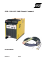 1
1
-
 2
2
-
 3
3
-
 4
4
-
 5
5
-
 6
6
-
 7
7
-
 8
8
-
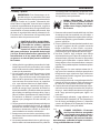 9
9
-
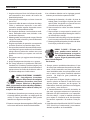 10
10
-
 11
11
-
 12
12
-
 13
13
-
 14
14
-
 15
15
-
 16
16
-
 17
17
-
 18
18
-
 19
19
-
 20
20
-
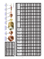 21
21
-
 22
22
-
 23
23
-
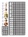 24
24
-
 25
25
-
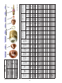 26
26
-
 27
27
-
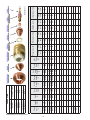 28
28
-
 29
29
-
 30
30
-
 31
31
-
 32
32
-
 33
33
-
 34
34
-
 35
35
-
 36
36
-
 37
37
-
 38
38
-
 39
39
-
 40
40
-
 41
41
-
 42
42
-
 43
43
-
 44
44


ESAB ESP-150 & PT-36R Direct Connect Manual de usuario
- Categoría
- Sistema de soldadura
- Tipo
- Manual de usuario
en otros idiomas
Artículos relacionados
-
ESAB PCC-14 Plumbing Box Manual de usuario
-
-
-
-
-
-
-
-
-
