GE JVM3162RJSS Guía de instalación
- Categoría
- Microondas
- Tipo
- Guía de instalación
Este manual también es adecuado para

READ CAREFULLY.
KEEP THESE INSTRUCTIONS.
Installation Over the Range
Instructions Microwave Oven
Read these instructions completely and carefully.
• IMPORTANT – Save these
instructions for local inspector’s use.
• IMPORTANT – Observe all
governing codes and ordinances.
• Note to Installer – Be sure to leave these
instructions with the Consumer.
BEFORE YOU BEGIN
• Note to Consumer – Keep these
instructions for future reference.
• Skill level – Installation of this appliance requires
basic mechanical and electrical skills.
• Proper installation is the responsibility of the installer.
• Product failure due to improper installation is not
covered under the Warranty.
31-7000173 Rev. 1 05-23 GEA

231-7000173 Rev. 1
IMPORTANT SAFETY INSTRUCTIONS
A qualified electrician must perform a ground
continuity check on the wall receptacle before
beginning the installation to ensure that the
outlet box is properly grounded. If not properly
grounded, or if the wall receptacle does not meet
electrical requirements noted (under ELECTRICAL
REQUIREMENTS), a qualified electrician should be
employed to correct any deficiencies.
Risk of Electric Shock.
Can cause injury
or death: Remove
house fuse or open
circuit breaker before
beginning installation
to avoid severe or fatal
shock injury.
Risk of Electric Shock.
Can cause injury or
death: THIS APPLIANCE
MUST BE PROPERLY
GROUNDED to avoid
severe or fatal shock.
The power cord of this appliance is equipped
with a three-prong (grounding) plug which mates
with a standard three-prong (grounding) wall
receptacle to minimize the possibility of electric
shock hazard from this appliance.
Where a standard two-prong wall receptacle is
encountered, it must be replaced with a properly
grounded three-prong wall receptacle, installed
by a qualified electrician.
Ensure
proper
ground
exists before
use
FOR YOUR SAFETY:
For personal safety, the
mounting surface must be
capable of supporting the cabinet load, in addition to
the added weight of this 63–85 pound product, plus
additional oven loads of up to 50 pounds or a total
weight of 113–135 pounds.
For personal safety, this product
cannot be installed in cabinet
arrangements such as an island or a peninsula. It
must be mounted to BOTH a top cabinet AND a wall.
To avoid the risk of personal
injury (back injury or other injuries
due to excessive weight of the microwave oven) or
property damage, you will need two people to install
this microwave oven.
This is the safety alert symbol. This symbol alerts you to potential hazards that can kill or hurt you and others.
All safety messages will follow the safety alert symbol and the word “DANGER”, “WARNING”, or “CAUTION”. These
words are defined as:
DANGER
Indicates a hazardous situation which, if not avoided, will result in death or serious injury.
WARNING Indicates a hazardous situation which, if not avoided, could result in death or serious injury.
CAUTION Indicates a hazardous situation which, if not avoided, could result in minor or moderate injury.
ELECTRICAL REQUIREMENTS
Product rating is 120 volts AC, 60 Hertz, 14.5 amps
and 1.7 kilowatts. This product must be connected to
a supply circuit of the proper voltage and frequency.
Wire size must conform to the requirements of
the National Electrical Code or the prevailing local
code for this kilowatt rating. The power supply cord
and plug should be brought to a separate 15- to
20-ampere branch circuit single grounded outlet. The
outlet box should be located in the cabinet above
the microwave oven. The outlet box and supply
circuit should be installed by a qualified electrician
and conform to the National Electrical Code or the
prevailing local code.
CAUTION
CAUTION
CAUTION
RISK OF ELECTRIC SHOCK
Can cause injury or death: DO
NOT, under any circumstances,
cut, deform or remove any of the prongs from the
power cord. Do not use with an extension cord.
Failure to comply may cause fire.
WARNING
WARNING
WARNING
Installation Instructions

31-7000173 Rev. 1 3
Installation Instructions
HOOD EXHAUST
The following chart describes an example of one possible ductwork installation.
NOTE: Read these next two pages only if you plan to vent your exhaust to the outside. If you plan to recirculate the air back
into the room, proceed to page 11.
OUTSIDE TOP EXHAUST (EXAMPLE ONLY)
NOTE: For back exhaust, care should be taken to align exhaust with space between studs, or wall
should be prepared at the time it is constructed by leaving enough space between the wall studs to
accommodate exhaust.
* IMPORTANT: If a rectangular-to-round transition adaptor is used, the bottom corners of the damper
will have to be cut to fit, using the tin snips, in order to allow free movement of the damper.
The following chart describes an example of one possible ductwork installation.
OUTSIDE BACK EXHAUST (EXAMPLE ONLY)
EQUIVALENT NUMBER
DUCT PIECES LENGTH x USED = LENGTH
Roof Cap 24 Ft. x (1) = 24 Ft.
12 Ft. Straight Duct 12 Ft. x (1) = 12 Ft.
Ǝ5RXQG
Rectangular-to-Round 5 Ft. x (1) = 5 Ft.
Transition Adaptor*
Equivalent lengths of duct pieces are based on actual tests and
reflect requirements for good venting performance with any vent hood.
Total Length = 41 Ft.
EQUIVALENT NUMBER
DUCT PIECES LENGTH* x USED = LENGTH
Wall Cap 40 Ft. x (1) = 40 Ft.
3 Ft. Straight Duct 3 Ft. x (1) = 3 Ft.
(31»4Ǝ[Ǝ5HFWDQJXODU
90° Elbow 10 Ft. x (2) = 20 Ft.
Equivalent lengths of duct pieces are based on actual tests and
reflect requirements for good venting performance with any vent hood.
Total Length = 63 Ft.

431-7000173 Rev. 1
Installation Instructions
EQUIVALENT NUMBER
DUCT PIECES LENGTH x USED = LENGTH
Rectangular-to-Round 5 Ft. x ( ) = Ft.
Transition Adaptor*
Wall Cap 40 Ft. x ( ) = Ft.
90° Elbow 10 Ft. x ( ) = Ft.
45° Elbow 5 Ft. x ( ) = Ft.
90° Elbow 25 Ft. x ( ) = Ft.
45° Elbow 5 Ft. x ( ) = Ft.
Roof Cap 24 Ft. x ( ) = Ft.
6WUDLJKW'XFWƎ5RXQGRU )W [ )W
3
1»4Ǝ[Ǝ5HFWDQJXODU
Total Ductwork = Ft.
Equivalent lengths of duct pieces are based on actual tests
and reflect requirements for good venting performance with
any vent hood.
* IMPORTANT: If a rectangular-to-round transition
adaptor is used, the bottom corners of the
damper will have to be cut to fit, using the tin
snips, in order to allow free movement of the
damper
.
NOTE: If you need to install ducts, note that the total
duct length of 31»4Ǝ[ƎUHFWDQJXODURUƎGLDPHWHUURXQG
duct should not exceed 140 equivalent feet.
Outside ventilation requires a HOOD EXHAUST DUCT.
Read the following carefully.
NOTE: It is important that venting be installed using
the most direct route and with as few elbows as possible.
This ensures clear venting of exhaust and helps prevent
blockages. Also, make sure dampers swing freely and
nothing is blocking the ducts.
Exhaust connection:
The hood exhaust has been designed to mate with
a standard 31»4Ǝ[ƎUHFWDQJXODUGXFW
If a round duct is required, a rectangular-to-round
transition adaptor must be used. Do not use less than
a 6Ǝ diameter duct.
Maximum duct length:
For satisfactory air movement, the total duct length of
31»4Ǝ[ƎUHFWDQJXODURUƎGLDPHWHUURXQGGXFWshould
not exceed 140 equivalent feet.
Elbows, transitions, wall and roof caps,
etc., present additional resistance to airflow and are
equivalent to a section of straight duct which is longer
than their actual physical size. When calculating the total
duct length, add the equivalent lengths of all transitions
and adaptors plus the length of all straight duct sections.
The chart below shows you how to calculate total
equivalent ductwork length using the approximate feet of
equivalent length of some typical ducts.

31-7000173 Rev. 1 5
Installation Instructions
MOUNTING SPACE •7KHVSDFHEHWZHHQWKHFDELQHWVPXVWEHƎZLGH
and free of obstructions.
• This oven is for installation over ranges up to
ƎZLGH
• If the space between the cabinets is greater than
30”, a Filler Panel Kit may be used to fill in the gap
between the microwave oven and the cabinets. Your
Owner’s Manual contains the kit number for your
model.
• If you are going to vent your oven to the outside, see
Hood Exhaust Section for exhaust duct preparation.
• When installing the oven beneath smooth, flat
cabinets, be careful to follow the instructions on the
top cabinet template for power cord clearance.
• * 13” max: for standard installation, 15” cabinet
depth requires additional steps using an additional
installation kit JX15BUMPWW/BB.
• For models with top venting holes: Do not allow
cabinetry or other objects to block the airflow of the vent.
• This microwave is suitable for installation over electric or
gas cooking appliances with a combined BTU of 63,000
BTU or less.
• Café branded gas cooking appliances should only be
installed in combination with a Café branded over-the-
range microwave.
• Monogram branded gas cooking appliances should only
be installed in combination with a Monogram branded
over-the-range microwave.
• Monogram branded gas cooking appliances with a
combined BTU greater than 66,000 BTU should not be
paired with an over-the-range microwave.
Backsplash
ƎRUPRUH
from the floor
to the top of
the oven
Ǝ
2Ǝ
Ǝ
min.
16-1»2Ǝ
Bottom edge of
cabinet needs
WREHƎRU
more from the
cooking surface
ƎPD[
TOOLS YOU WILL NEED
#1 and #2 Phillips
screwdriver
Pencil
Ruler or tape measure and
straight edge
Carpenter square
(optional)
Tin snips (for cutting
damper, if required)
Electric drill with 3»16Ǝ7»16Ǝ
1»2ƎDQG5»8ƎGULOOELWV
Hammer (optional)
Stud
finder
Filler blocks or scrap
wood pieces, if needed
for top cabinet spacing
(used on recessed
bottom cabinet
installations only)
Gloves Saw (saber, hole or keyhole)
Level Duct and masking
tape
Scissors (to cut
template, if necessary)
Safety goggles

631-7000173 Rev. 1
PARTS INCLUDED
You will find the installation hardware contained in a
packet with the unit. Check to make sure you have all
these parts.
NOTE: Some extra parts are included.
HARDWARE PACKET
ADDITIONAL PARTS
Installation Instructions - Straight Mounting Plate
DAMAGE – SHIPMENT INSTALLATION
•If the unit is damaged in shipment, return the
unit to the store in which it was bought for repair or
replacement.
•If the unit is damaged by the customer, repair or
replacement is the responsibility of the customer.
•If the unit is damaged by the installer (if other
than the customer), repair or replacement must
be made by arrangement between customer and
installer.
Part Quantity
Wood screws (1/4” x 2”) 2
Toggle bolts (and wind
nuts) (3/16” x 3”)
2
Self-aligning machine
screws (1/4” - 28 x 3
1/4”)
2
Nylon Grommet (for
metal cabinets)
1
Tapping screws (for
attaching the damper
duct connector)
2-3
One power cord clamp
and One dark-colored
mounting screw (to hold
the power cord)
1
Part Quantity
Top Cabinet
Template
1
Rear Wall
Template
1
Installation
Instructions
1
Separately
Packed Grease
Filter
2
Mounting Plate
(for supporting
the microwave
Oven)
1
Cover plate (for
Room Venting
installation)
1

31-7000173 Rev. 1 7
Find the studs, using one of the following
methods:
A. Stud finder – a magnetic device which
locates nails.
OR
B. Use a hammer to tap lightly across the
mounting surface to find a solid sound.
This will indicate a stud location.
After locating the stud(s), find the center by
probing the wall with a small nail to find the edges
of the stud. Then place a mark halfway between
the edges. The center of any adjacent studs
VKRXOGEHƎRUƎIURPWKLVPDUN
Draw a line down the center of the studs.
THE MICROWAVE MUST BE CONNECTED TO
AT LEAST ONE WALL STUD.
1
Remove the installation instructions, filters, glass
tray, mounting plate, and the small hardware bag.
Do not remove the foam protecting the front of the
oven.
Fold back all 4 carton flaps fully against carton
sides. Then carefully roll the oven and carton over
onto the top side. The oven should be resting in
the foam.
REMOVING THE MICROWAVE
OVEN FROM THE CARTON
FINDING THE WALL STUDS
A.
2
PLACEMENT OF THE MOUNTING PLATE
1
Wall
Studs
Center
3
Pull the carton up and off the oven.
Carton
Foam
Installation Instructions
2
3
Set the oven upright. Remove and properly discard
plastic bags and foam packing.
4
1
B.

831-7000173 Rev. 1
Installation Instructions
DETERMINING MOUNTING PLATE LOCATION UNDER YOUR CABINET
C
Plate Position – beneath flat bottom
cabinet Plate Position – beneath framed
recessed cabinet bottom
3
2
Draw a vertical line on the wall at the center of the
30” space.
Tape the Rear Wall Template onto the wall
matching the centerline and touching the bottom
cabinet frame.
30” to Cooktop
Plate Position – beneath recessed
bottom cabinet with front overhang.
30” to Cooktop
Draw a line on the
back wall equal to
the depth of the front
overhang
Your cabinets may have decorative trim that interferes
with the microwave installation. Remove the decorative
trim to install the microwave properly and to make it
level.
THE MICROWAVE MUST BE LEVEL
Use a level to make sure the cabinet bottom is level.
If the cabinets have a front overhang only, with no
back or side frame, install the mounting plate down the
same distance as the front overhang depth. This will
keep the microwave level.
Measure the inside depth of the front overhang.
Draw a horizontal line on the back wall an equal
distance below the cabinet bottom as the inside
depth of the front overhang.
For this type of installation with front overhang only,
align the Rear Wall Template with this horizontal
line, not touching the cabinet bottom as described
in Step D.
Draw a vertical line on the wall at the center of the
30” wide space. Tape the Rear Wall Template onto
the wall matching the centerline and touching the
bottom of the cabinet.
1

31-7000173 Rev. 1 9
Installation Instructions
MARKING THE MOUNTING HOLES
OPTION 1: USE PAPER REAR WALL TEMPLATE
WARNING Risk of electric shock. Can cause
injury or death. Take care to not drill into electrical
wiring inside walls or cabinets.
This Rear Wall Template serves to locate the mounting
holes for the bottom mounting plate and to locate the
horizontal exhaust outlet.
1. Use a level to check that the template is positioned
accurately.
2. Locate and mark at least one stud on the left or right
side of the centerline.
NOTE: It is important to use at least one wood screw
mounted firmly in a stud to support the weight of the
microwave.
3. Mark the hole location on the wall using the template
at holes A and B. Mark at least one hole location
in area C that lines up with the location of a stud. A
minimum of three holes must be used for mounting.
4. Drill holes in the marked locations. Where there is a
stud, drill a 3/16” hole for wood screws. For holes that
do not line up with a stud, drill 5/8” holes for toggle
bolts.
NOTE: DO NOT INSTALL THE MOUNTING PLATE AT
THIS TIME
5. Remove the template from the rear wall.
D
CAUTION Wear gloves to avoid cutting fingers
on sharp edges.
CUT HOLE THROUGH REAR WALL FOR EXHAUST ADAPTOR
12"
4"
NOTE: IT IS VERY IMPORTANT TO
READ AND FOLLOW THE DIRECTIONS
IN THE INSTALLATION INSTRUCTIONS
BEFORE PROCEEDING WITH THIS
REAR WALL TEMPLATE.
This Rear Wall Template serves to position the bottom
mounting plate and to locate the horizontal exhaust
outlet.
1. Use a level to check that the template is positioned
accurately.
2. Locate and mark at least one stud on the left or
right side of the centerline.
NOTE:It is important to use at least one wood
screw mounted firmly in a stud to support the weight
of the microwave. Mark two additional, evenly spaced
locations for the supplied toggle bolts.
3. Drill holes in the marked locations. Where there is
a stud, drill a 3/16" hole for wood screws. For holes
that do not line up with a stud, drill 5/8" holes for
toggle bolts.
NOTE::DO NOT INSTALL THE MOUNTING PLATE
AT THIS TIME.
4. Remove the template from the rear wall.
5. Review the Installation Instruction book for your
installation situation.
Darle vuelta a la hoja para consultar la
versión en Español.
CAUTION - IF EXHAUST ADAPTOR IS POSITIONED OUTSIDE
RECOMMENDED DIMENSION, GREASE-LADEN AIR WILL
DISCHARGE INTO HOUSE STRUCTURE
30” MINIMUM WIDTH REQUIRED
REAR WALL TEMPLATE
F. CUT OUT FOR HORIZONTAL
OUTSIDE EXHAUST
Locate and mark holes to align with holes in the
mounting plate.
IMPORTANT:
LOCATE AT LEAST ONE STUD ON EITHER SIDE OF
THE CENTERLINE.
MARK THE LOCATION FOR 2 ADDITIONAL, EVENLY
SPACED TOGGLE BOLTS IN THE MOUNTING PLATE
AREA.
Locate and mark holes to align with holes in the
mounting plate.
IMPORTANT:
LOCATE AT LEAST ONE STUD ON EITHER SIDE OF
THE CENTERLINE.
MARK THE LOCATION FOR 2 ADDITIONAL, EVENLY
SPACED TOGGLE BOLTS IN THE MOUNTING PLATE
AREA.
Trim the rear wall template along the dotted line.
3/8" TO EDGE
C
NOTES:
- 13” Max Cabinet Depth
- 15” deep cabinets require additional steps using
an additional installation kit: JX15BUMP
OPTION 1 OPTION 2
STEP 1: Installer uses bracket to make 2 marks. First
mark is made by using the stampled slot in bracket.
Second mark is made on the ouside edge of bracket.
STEP 3: Installer uses a level to draw a horizontal line
that connects the two marks made with the stamped
slot in the bracket.
STEP 2: Installer moves bracket to the other side of
the cabinets and makes 2 more marks. Marks are the
same as STEP 1, just opposite side.
STEP 4: Installer uses marks to install bracket in
correct position. The bracket is to be installed per
standard requirements (at least one wood screw
mounted in a stud, two additional evenly spaced
locations for toggle bolts). Mark hole location A,B, C and
D by placing the mounting bracket on the wall as shown
in the picture. Hole C and or D must be in a WALL STUD.
STEP 5: Set mounting bracket aside and drill holes at
all marked locations. If there is a stud, drill a 3/16” hole
for wood screws. For holes that do not line up with a
stud, drill a 5/8” hole for a toggle bolt.
Make a mark here, along
inside bottom of the
stamped slot provided.
Make a mark
here,
even with
bottom of
stamped
slot
Make a mark here, along
inside bottom of the
stamped slot provided
(same as Step 1).
Make a
mark here,
even with
bottom of
stamped
slot
Horizontal line
A
C
D
B
Place bracket within the lines created in previous steps.
Mark hole locations for A, B, C, and D.
NOTE: Refer to step C “DETERMINING MOUNTING PLATE LOCATION UNDER YOUR CABINET on page 10 for aligning instructions.
C
AB
30”

10 31-7000173 Rev. 1
Installation Instructions
D
STEP 2: Installer uses bracket to make 2 marks. First
mark is made by using the stamped slot in bracket. Second
mark is made on the outside edge of bracket.
STEP 1: Draw a vertical line on the wall at the center of
the 30” space. STEP 4: Installer uses a level to draw a horizontal line
that connects the two marks made with the stamped slot in
the bracket.
STEP 5: Installer places the mounting bracket on the wall
as shown in the picture. Draw circles on the wall at holes A
and B. Draw at least one circle in area C. At least one circle
MUST line up with a wall stud.
STEP 6: Set mounting bracket aside and drill holes at
all marked locations. If there is a stud, drill a 3/16” hole for
wood screws. For holes that do not line up with a stud, drill a
5/8” hole for a toggle bolt.
Make a mark here, along inside
bottom of the stamped slot
provided.
Make a mark
here on the
outside edge
of the bracket
Horizontal line
NOTE: Refer to step C “DETERMINING MOUNTING PLATE LOCATION UNDER YOUR CABINET on page 8 for aligning instructions.
MARKING THE MOUNTING HOLES
OPTION 2: USE METAL BRACKET AS TEMPLATE
STEP 3: Installer moves bracket to the other side of the
cabinets and makes 2 more marks. Marks are the same as
STEP 2, just opposite side.
Make a mark here, along
inside bottom of the
stamped slot provided
(same as Step 1).
Make a mark
here on the
outside edge of
the bracket
A
C
B
Place bracket within the lines created in previous steps.
Mark hole locations for
A, B, and area C.

31-7000173 Rev. 1 11
INSTALLATION TYPES
(Choose A, B or C)
This microwave oven is designed for adaptation to
the following three types of ventilation:
A. Recirculating (Non-Vented Ductless)
B. Outside Top Exhaust (Vertical Duct)
C. Outside Back Exhaust (Horizontal Duct)
NOTE: Select the type of ventilation required for your
installation and proceed to that section.
BOUTSIDE TOP EXHAUST
(VERTICAL DUCT)
See page 16
Adaptor in Place
for Outside Top
Exhaust
Installation Instructions
2
OUTSIDE BACK EXHAUST
(HORIZONTAL DUCT)
See page 20
C
RECIRCULATING
(NON-VENTED DUCTLESS)
See page 12
A Charcoal Filter Accessory Kit is required for the
non-vented exhaust. (See your Owner’s Manual for the
kit number.)
A

12 31-7000173 Rev. 1
Installation Instructions
USE TOP CABINET TEMPLATE
FOR PREPARATION OF TOP
CABINET
A2
RECIRCULATING (Non-Vented Ductless)
CUT HOLE THROUGH REAR WALL FOR EXHAUST ADAPTOR
12"
4"
NOTE: IT IS VERY IMPORTANT TO
READ AND FOLLOW THE DIRECTIONS
IN THE INSTALLATION INSTRUCTIONS
BEFORE PROCEEDING WITH THIS
REAR WALL TEMPLATE.
This Rear Wall Template serves to position the bottom
mounting plate and to locate the horizontal exhaust
outlet.
1. Use a level to check that the template is positioned
accurately.
2. Locate and mark at least one stud on the left or
right side of the centerline.
NOTE:
It is important to use at least one wood
screw mounted firmly in a stud to support the weight
of the microwave. Mark two additional, evenly spaced
locations for the supplied toggle bolts.
3. Drill holes in the marked locations. Where there is
a stud, drill a 3/16" hole for wood screws. For holes
that do not line up with a stud, drill 5/8" holes for
toggle bolts.
NOTE::
DO NOT INSTALL THE MOUNTING PLATE
AT THIS TIME.
4. Remove the template from the rear wall.
5. Review the Installation Instruction book for your
installation situation.
Darle vuelta a la hoja para consultar la
versión en Español.
CAUTION - IF EXHAUST ADAPTOR IS POSITIONED OUTSIDE
RECOMMENDED DIMENSION, GREASE-LADEN AIR WILL
DISCHARGE INTO HOUSE STRUCTURE
30” MINIMUM WIDTH REQUIRED
REAR WALL TEMPLATE
F. CUT OUT FOR HORIZONTAL
OUTSIDE EXHAUST
Locate and mark holes to align with holes in the
mounting plate.
IMPORTANT:
LOCATE AT LEAST ONE STUD ON EITHER SIDE OF
THE CENTERLINE.
MARK THE LOCATION FOR 2 ADDITIONAL, EVENLY
SPACED TOGGLE BOLTS IN THE MOUNTING PLATE
AREA.
Trim the rear wall template along the dotted line.
3/8" TO EDGE
C
A
C
D
B
NOTES:
- 13” Max Cabinet Depth
- 15” deep cabinets require additional steps using
an additional installation kit: JX36BUMP
OPTION 1
OPTION 2
STEP 1:
Installer uses bracket to make 2 marks. First
mark is made by using the stampled slot in bracket.
Second mark is made on the ouside edge of bracket.
STEP 2:
Installer moves bracket to the other side of
the cabinets and makes 2 more marks. Marks are the
same as STEP 1, just opposite side.
STEP 4:
Make a mark here, along
inside bottom of the
stamped slot provided.
Make a mark
here,
even with
bottom of
stamped
slot
Make a mark here, along
inside bottom of the
stamped slot provided
(same as Step 1).
Make a
mark here,
even with
bottom of
stamped
slot
Horizontal line
A
C
D
B
INSTALLATION OVERVIEW
A1. Attach Mounting Plate to Wall
A2. Prepare Top Cabinet
A3. Check Blower Orientation
A4. Adapting Microwave Blower For Recirculation
A5. Mount the Oven
A6. Installing The Charcoal Filter
• Read the instructions on the TOP CABINET
TEMPLATE.
• Tape it underneath the top cabinet.
• Drill the holes, following the instructions on the
TOP CABINET TEMPLATE.
CAUTION
Wear safety goggles when drilling
holes in the cabinet bottom.
You need to drill holes for the top support screws and
a hole large enough for the power cord to fit through.
A
Place the mounting plate against the wall and
insert the toggle wings into the holes in the wall to
mount the plate.
CAUTION Be careful to avoid pinching
fingers between the back of the mounting plate
and the wall.
Tighten all bolts. Pull the plate away from the wall
to help tighten the bolts.
3
ATTACH THE MOUNTING
PLATE TO THE WALL
A1
A
C
D
B
Attach the plate to the wall using toggle bolts and
wood screws. At least one wood screw must be
used to attach the plate to a wall stud.
Remove the toggle wings from the bolts.
Insert the bolts into the mounting plate through
the holes designated to go into drywall and
reattach the toggle wings to 3»4ƎRQWRHDFKEROW
1
4
To use toggle bolts:
Wall
Mounting
Plate
Spacing for Toggles More
Than Wall Thickness
Bolt End
Toggle
Bolt
Toggle Wings
2
IMPORTANT: Do NOT
remove the cardboard spacers
between the heat shield and
door

31-7000173 Rev. 1 13
Installation Instructions
AFTER: Fan Blade
Openings Facing
Forward
3
2
4
ADAPTING BLOWER
FOR RECIRCULATION
A4.
NOTE: The exhaust adaptor with damper is not needed
for recirculating models. You may want to save them
for possible future use.
Carefully pull out the blower unit. The wires will
extend far enough to allow you to adjust the blower
unit.
Roll the blower unit 90° so that fan blade openings
are facing toward the front of the oven.
Roll
Slide the blower plate from under its retaining
flange and lift it off. Remove the cover plate
installed on the back. Remove and save screws
that hold blower unit to the oven.
Remove and save screws that hold blower plate
to the oven.
BEFORE: Fan Blade
Openings Facing Up
1
Blower Plate
Back of
Oven
Cover Plate
Blower Plate Screws
CHECK BLOWER MOTOR
ORIENTATION
The blower fan blade opening should be facing the
front of the microwave. You will have to remove the
top cover plate to check the fan blade orientation.
If the fan opening is already facing the front of the
microwave, skip to step A5. Otherwise, continue to
Step A4 to adjust the fan motor orientation.
A3.
Blower
Plate
Retaining
Flange
Blower Motor
Screws
Cover Plate

14 31-7000173 Rev. 1
Installation Instructions
1
6
5
ADAPTING BLOWER FOR
RECIRCULATION (continued)
A4.
Replace blower motor screws removed in Step 2.
Slide cover plate into position on the back of the
unit. Replace blower plate and screws removed in
Step 1. Attach second cover plate on blower plate
(including one screw). 2Rotate front of oven
up against cabinet
bottom.
MOUNT THE OVEN
A5.
FOR EASIER INSTALLATION AND PERSONAL
SAFETY, WE RECOMMEND THAT TWO PEOPLE
INSTALL THIS OVEN.
IMPORTANT: Do not grip or use handle
during installation.
NOTE: If your cabinet is metal, use the nylon
grommet around the power cord hole to prevent
cutting of the cord.
NOTE: We recommend using filler blocks if the
cabinet front hangs below the cabinet bottom shelf.
IMPORTANT: If filler blocks are not used,
case damage may occur from over
tightening screws.
NOTE: When mounting
the oven, thread power
cord through hole in
bottom of top cabinet.
Keep it tight throughout
Steps 1–3. Do not pinch
cord or lift oven by pulling
cord.
Lift oven, tilt it
forward and hook
slots at back bottom
edge onto two lower
tabs of mounting plate.
Cabinet Front
Cabinet Bottom Shelf
Filler Block
Oven Top
Equivalent to
Depth of Cabinet
Recess
Self-Aligning Screw
Blower Plate
Back of
Oven
Blower
Plate
Screws
Blower Motor Screws
Cover Plate
Cover Plate
Place the blower unit back into the opening.
CAUTION Do not pull or stretch the
blower unit wiring. Make sure the wires are
not pinched.

31-7000173 Rev. 1 15
Installation Instructions
3
WHEN REPLACING THE
CHARCOAL FILTER
A6.
MOUNT THE OVEN
(continued)
A5.
Slide the old filter down and out to remove it.
Remove plastic and other outer wrapping from
the new filter and install the new filter. When
properly installed, the wire mesh of the filter
should be visible from the front.
Replace the grille and the 2 screws.
Close the door.
If the model is not vented to the outside, the air will
be recirculated through a disposable charcoal filter
that helps remove smoke and odors.
The charcoal filter should be replaced when it is
noticeably dirty or discolored (usually after 6 to
12 months, depending on hood usage). See your
Owner’s Manual for the filter kit number.
To replace the charcoal filter:
Open the microwave door.
Remove 2 screws from the top of the grille. (You
may need to open the cabinet doors to remove the
screws.
Slide the grille to the left and forward to remove.
5
4
Tighten the two screws to the top of the oven
completely. (While tightening screws, hold
the oven in place against the wall and the top
cabinet.)
Attach the oven to the top cabinet by inserting
2 self-aligning screws through outer top cabinet
holes. Turn two full turns on each screw. Be
sure to keep power cord tight. Be careful not
to pinch the cord, especially when mounting
flush to bottom of cabinet.
Install grease filters. See the Owner’s Manual
packed with the oven.
5
Insert filter mesh-side up
Charcoal
Filter
6
4
7
3
2
1

16 31-7000173 Rev. 1
OUTSIDE TOP EXHAUST
(Vertical Duct)
Insert the toggle wings into the holes in the wall
and place the mounting plate against the wall.
CAUTION Be careful to avoid pinching
fingers between the back of the mounting plate
and the wall.
Tighten all bolts. Pull the plate away from the wall
to help tighten the bolts.
3
B
4
ATTACH THE MOUNTING
PLATE TO THE WALL
B1
Attach the plate to the wall using toggle bolts and
wood screws. At least one wood screw must be used
to attach the plate to a wall stud.
Remove the toggle wings from the bolts.
Insert the bolts into the mounting plate through
the holes designated to go into drywall and reattach
the toggle wings to 3»4ƎRQWRHDFKEROW
1
CUT HOLE THROUGH REAR WALL FOR EXHAUST ADAPTOR
12"
4"
NOTE: IT IS VERY IMPORTANT TO
READ AND FOLLOW THE DIRECTIONS
IN THE INSTALLATION INSTRUCTIONS
BEFORE PROCEEDING WITH THIS
REAR WALL TEMPLATE.
This Rear Wall Template serves to position the bottom
mounting plate and to locate the horizontal exhaust
outlet.
1. Use a level to check that the template is positioned
accurately.
2. Locate and mark at least one stud on the left or
right side of the centerline.
NOTE:
It is important to use at least one wood
screw mounted firmly in a stud to support the weight
of the microwave. Mark two additional, evenly spaced
locations for the supplied toggle bolts.
3. Drill holes in the marked locations. Where there is
a stud, drill a 3/16" hole for wood screws. For holes
that do not line up with a stud, drill 5/8" holes for
toggle bolts.
NOTE::
DO NOT INSTALL THE MOUNTING PLATE
AT THIS TIME.
4. Remove the template from the rear wall.
5. Review the Installation Instruction book for your
installation situation.
Darle vuelta a la hoja para consultar la
versión en Español.
CAUTION - IF EXHAUST ADAPTOR IS POSITIONED OUTSIDE
RECOMMENDED DIMENSION, GREASE-LADEN AIR WILL
DISCHARGE INTO HOUSE STRUCTURE
30” MINIMUM WIDTH REQUIRED
REAR WALL TEMPLATE
F. CUT OUT FOR HORIZONTAL
OUTSIDE EXHAUST
Locate and mark holes to align with holes in the
mounting plate.
IMPORTANT:
LOCATE AT LEAST ONE STUD ON EITHER SIDE OF
THE CENTERLINE.
MARK THE LOCATION FOR 2 ADDITIONAL, EVENLY
SPACED TOGGLE BOLTS IN THE MOUNTING PLATE
AREA.
Trim the rear wall template along the dotted line.
3/8" TO EDGE
C
A
C
D
B
NOTES:
- 13” Max Cabinet Depth
- 15” deep cabinets require additional steps using
an additional installation kit: JX36BUMP
OPTION 1
OPTION 2
STEP 1:
Installer uses bracket to make 2 marks. First
mark is made by using the stampled slot in bracket.
Second mark is made on the ouside edge of bracket.
STEP 2:
Installer moves bracket to the other side of
the cabinets and makes 2 more marks. Marks are the
same as STEP 1, just opposite side.
STEP 4:
Make a mark here, along
inside bottom of the
stamped slot provided.
Make a mark
here,
even with
bottom of
stamped
slot
Make a mark here, along
inside bottom of the
stamped slot provided
(same as Step 1).
Make a
mark here,
even with
bottom of
stamped
slot
Horizontal line
A
C
D
B
INSTALLATION
OVERVIEW
B1. Attach Mounting Plate to Wall
B2. Prepare Top Cabinet
B3. Check Motor Orientation
B4. Adapting For Outside
Ventilation
B5. Assemble and Install Adaptor
B6. Mount the Microwave
B7. Adjust The Exhaust Adaptor
B8. Connecting Ductwork
To use toggle bolts:
2
Wall
Mounting
Plate
Mounting Plate
Spacing for Toggles More
Than Wall Thickness
Bolt End
Toggle
Bolt
Toggle Wings
Installation Instructions
IMPORTANT: Do NOT remove the
cardboard spacers between the
heat shield and door
A
C
D
B

31-7000173 Rev. 1 17
Installation Instructions
ADAPTING BLOWER FOR
OUTSIDE VENTILATION
CHECK BLOWER MOTOR
ORIENTATION
The blower fan blade opening should be facing the top
of the microwave. If the fan opening is already facing
the top of the microwave, skip to Step B5. Otherwise,
continue to Step B4 to adjust the motor orientation.
B3.
3
2
4
B4.
Carefully pull out the blower unit. The wires
will extend far enough to allow you to adjust the
blower unit.
Roll the blower unit 90° so that fan blade openings
are facing toward the top of the microwave.
Roll
Slide the blower plate from under its retaining
flange and lift it off. Remove the cover plate
installed on the back. Remove and save screws
that hold blower unit to the oven.
Remove the cover installed on the blower plate
(including one screw). Remove and save screws
holding blower plate to the oven.
BEFORE: Fan Blade
Openings Facing
Front
1
Blower
Plate
Cover Plate
Blower Motor Screws
Retaining
Flange
AFTER: Fan
Blade Openings
Facing Up
USE TOP CABINET TEMPLATE
FOR PREPARATION OF TOP
CABINET
You need to drill holes for the top support screws, a
hole large enough for the power cord to fit through,
and a cutout large enough for the exhaust adaptor.
B2
• Read the instructions on the TOP CABINET
TEMPLATE.
• Tape it underneath the top cabinet.
• Drill the holes, following the instructions on the TOP
CABINET TEMPLATE.
CAUTION Wear safety goggles when drilling
holes in the cabinet bottom.
A
C
D
B
Blower Plate
Back of
Oven
Blower
Plate
Screws
Blower Motor Screw
Cover Plate
Cover Plate

18 31-7000173 Rev. 1
Installation Instructions
ASSEMBLE AND
INSTALL ADAPTOR
MOUNT THE OVEN
B6.
B5.
FOR EASIER INSTALLATION AND PERSONAL
SAFETY, WE RECOMMEND THAT TWO PEOPLE
INSTALL THIS OVEN.
IMPORTANT: Do not grip or use handle
during installation.
NOTE: If your cabinet is metal, use the nylon
grommet around the power cord hole to prevent
cutting of the cord.
NOTE: We recommend using filler blocks if the
cabinet front hangs below the cabinet bottom shelf.
IMPORTANT: If filler blocks are not
used, case damage may occur from over
tightening screws.
Place the oven in its upright position, with the top of
the unit facing up.
NOTE: Make sure the blower fan blades are
visible and are pointing up.
Insert the tabs on each side of the damper into the
holes at the inside rear of the adaptor.
1
2
Damper
Back of
Oven
Cover Plate
Exhaust
Adaptor
Blower Plate
NOTE: On some models, the exhaust adaptor and
damper assembly may already be assembled to the
oven.
6
5
Replace blower motor screws removed in Step 2.
Slide cover plate into position on the back of the
unit. Replace blower plate and screws removed in
Step 1.
ADAPTING BLOWER FOR
OUTSIDE VENTILATION
(continued)
B4. Attach the exhaust adaptor to the blower plate
with the two bronze metal screws provided.
Make sure that the damper pivots easily before
mounting oven.
You will need to make adjustments to assure
proper alignment with your house exhaust duct
after the oven is installed.
3
Blower Plate
Back of
Oven
Blower Plate Screws
Blower Motor Screws
Cover Plate
NOTE: When mounting the microwave, thread
power cord through hole in bottom of top cabinet.
Keep it tight throughout Steps 1–3. Do not pinch
cord or lift microwave oven by pulling cord.
Lift microwave, tilt it forward, and hook slots
at back bottom edge onto four lower tabs of
mounting plate.
Rotate front of microwave oven up against
cabinet bottom.
1
2
Power Cord
Place the blower unit back into the opening.
CAUTION Do not pull or stretch the
blower unit wiring. Make sure the wires are
not pinched.

31-7000173 Rev. 1 19
Installation Instructions
Attach the oven to the top cabinet by inserting
2 self-aligning screws through outer top cabinet
holes. Turn two full turns on each screw. Be sure
to keep power cord tight. Be careful not to
pinch the cord, especially when mounting flush
to bottom of cabinet.
3
5
4
Tighten the two screws to the top of the oven
completely. (While tightening screws, hold
the oven in place against the wall and the top
cabinet.)
Install grease filters. See the Owner’s Manual
packed with the oven.
ADJUST THE EXHAUST
ADAPTOR
B7.
Open the top cabinet and adjust the exhaust adaptor
to connect to the house duct.
CONNECTING DUCTWORK
1
2
Extend the house duct down to connect to
the exhaust adaptor.
Seal exhaust duct joints using duct tape.
B8.
House Duct
Cabinet Front
Cabinet Bottom Shelf
Filler Block
Oven Top
Equivalent
to Depth
of Cabinet
Recess
Self-Aligning Screw
MOUNT THE OVEN (continued)
B6.
Back of
Oven
Damper
Cover Plate

20 31-7000173 Rev. 1
OUTSIDE BACK EXHAUST
(Horizontal Duct)
PREPARING THE REAR WALL
FOR OUTSIDE BACK EXHAUST
C1
INSTALLATION OVERVIEW
C1. Prepare Rear Wall
C2. Attach Mounting Plate to Wall
C3. Prepare Top Cabinet
C4. Adjust Blower
C5. Mount The Oven
Installation Instructions
C
ATTACH THE MOUNTING
PLATE TO THE WALL
C2
Attach the plate to the wall using toggle bolts and wood
screw. At least one wood screw must be used to attach
the plate to a wall stud.
Remove the toggle wings from the bolts.
Insert the bolts into the mounting plate through
the holes designated to go into drywall and reattach
the toggle wings to 3»4ƎRQWRHDFKEROW
1
2
You need to cut an opening in the rear wall for
outside exhaust.
• Read the instructions on the REAR WALL
TEMPLATE.
• Tape it to the rear wall, lining up with the holes
previously drilled for holes A and B in the
mounting plate.
• Cut the opening, following the instructions of the
REAR WALL TEMPLATE.
A
C
D
B
To use toggle bolts:
Wall
Mounting
Plate
Spacing for Toggles More
Than Wall Thickness
Toggle
Bolt
Toggle Wings
Bolt
End
Insert the toggle wings into the holes in the wall
to mount the plate and place the mounting plate
against the wall.
CAUTION Be careful to avoid pinching
fingers between the back of the
mounting plate and the wall.
Tighten all bolts. Pull the plate away from the wall
to help tighten the bolts.
3
4
CUT HOLE THROUGH REAR WALL FOR EXHAUST ADAPTOR
12"
4"
NOTE: IT IS VERY IMPORTANT TO
READ AND FOLLOW THE DIRECTIONS
IN THE INSTALLATION INSTRUCTIONS
BEFORE PROCEEDING WITH THIS
REAR WALL TEMPLATE.
This Rear Wall Template serves to position the bottom
mounting plate and to locate the horizontal exhaust
outlet.
1. Use a level to check that the template is positioned
accurately.
2. Locate and mark at least one stud on the left or
right side of the centerline.
NOTE:
It is important to use at least one wood
screw mounted firmly in a stud to support the weight
of the microwave. Mark two additional, evenly spaced
locations for the supplied toggle bolts.
3. Drill holes in the marked locations. Where there is
a stud, drill a 3/16" hole for wood screws. For holes
that do not line up with a stud, drill 5/8" holes for
toggle bolts.
NOTE::
DO NOT INSTALL THE MOUNTING PLATE
AT THIS TIME.
4. Remove the template from the rear wall.
5. Review the Installation Instruction book for your
installation situation.
Darle vuelta a la hoja para consultar la
versión en Español.
CAUTION - IF EXHAUST ADAPTOR IS POSITIONED OUTSIDE
RECOMMENDED DIMENSION, GREASE-LADEN AIR WILL
DISCHARGE INTO HOUSE STRUCTURE
30” MINIMUM WIDTH REQUIRED
REAR WALL TEMPLATE
F. CUT OUT FOR HORIZONTAL
OUTSIDE EXHAUST
Locate and mark holes to align with holes in the
mounting plate.
IMPORTANT:
LOCATE AT LEAST ONE STUD ON EITHER SIDE OF
THE CENTERLINE.
MARK THE LOCATION FOR 2 ADDITIONAL, EVENLY
SPACED TOGGLE BOLTS IN THE MOUNTING PLATE
AREA.
Trim the rear wall template along the dotted line.
3/8" TO EDGE
C
A
C
D
B
NOTES:
- 13” Max Cabinet Depth
- 15” deep cabinets require additional steps using
an additional installation kit: JX36BUMP
OPTION 1
OPTION 2
STEP 1:
Installer uses bracket to make 2 marks. First
mark is made by using the stampled slot in bracket.
Second mark is made on the ouside edge of bracket.
STEP 2:
Installer moves bracket to the other side of
the cabinets and makes 2 more marks. Marks are the
same as STEP 1, just opposite side.
STEP 4:
Make a mark here, along
inside bottom of the
stamped slot provided.
Make a mark
here,
even with
bottom of
stamped
slot
Make a mark here, along
inside bottom of the
stamped slot provided
(same as Step 1).
Make a
mark here,
even with
bottom of
stamped
slot
Horizontal line
A
C
D
B
A
C
D
B

31-7000173 Rev. 1 21
Installation Instructions
USE TOP CABINET TEMPLATE
FOR
PREPARATION OF TOP
CABINET
C3.
• Read the instructions on the TOP CABINET
TEMPLATE.
• Tape it underneath the top cabinet.
• Drill the holes, following the instructions on the
TOP CABINET TEMPLATE.
CAUTION Wear safety goggles when drilling
holes in the cabinet bottom.
A
C
D
B
You need to drill holes for the top support screws and
a hole large enough for the power cord to fit through.
Roll the blower unit 90° so that fan blade
openings are facing out the back of the oven.
4
2
1
Remove and save the two screws that hold the
blower plate in place. Slide blower plate from
under its retaining flange. Remove the cover
plate installed on the back. Remove and save
screws that hold blower unit to the oven
ADAPTING BLOWER FOR
OUTSIDE BACK EXHAUST
C4.
Carefully pull out the blower unit. The wires
will extend far enough to allow you to adjust
the blower unit.
Before Rolling
Back of
Oven
After Rolling
Back of
Oven
BEFORE: Fan Blade
Openings Facing Up
Back of
Oven
3
Rotate blower unit counterclockwise 180°.
Before Rotation
Back of
Oven
After Rotation
Back of
Oven
Blower
Plate
Retaining
Flange

22 31-7000173 Rev. 1
Installation Instructions
Locate the two “knockout” plates, on the rear
oven panel, near the top of the oven.
Using tin snips, carefully cut the web area from
the two holes side-by-side (that secure the
knockouts to the oven). Cut all four webs on both
rear knockouts; this will allow the ventilation fan
airflow to exhaust out the rear of the oven.
CAUTION Be sure to trim the sharp
edges from the openings after removing the
knockout plates.
Place the blower unit back into the opening.
AFTER: Fan
Blade Openings
Facing Back
Replace the blower plate in the same position
as before and replace the screws for the blower
plate and blower motor. Attach the cover on the
blower plate with screw.
CAUTION Do not pull or stretch the
blower unit wiring. Make sure the wires are
not pinched.
NOTE: The blower unit exhaust openings
should match exhaust openings on rear of oven.
6
7
Snip all 4 webs
on each knockout
panel and remove
the metal
knockouts for rear
airflow.
Oven Rear Panel
5
Blower Plate
Back of Oven
Blower
Plate
Screws
Blower Motor
Screws
Cover Plate
MOUNT THE OVEN
C5.
FOR EASIER INSTALLATION AND PERSONAL
SAFETY, WE RECOMMEND THAT TWO PEOPLE
INSTALL THIS OVEN.
IMPORTANT: Do not grip or use handle
during installation.
NOTE: If your cabinet is metal, use the nylon
grommet around the power cord hole to prevent
cutting of the cord.
NOTE: We recommend using filler blocks if the
cabinet front hangs below the cabinet bottom shelf.
IMPORTANT: If filler blocks are not
used, case damage may occur from over
tightening screws.
NOTE: When mounting the microwave, thread
power cord through hole in bottom of top cabinet.
Keep it tight throughout Steps 1–3. Do not pinch
cord or lift microwave oven by pulling cord.
Lift microwave, tilt it forward, and hook slots
at back bottom edge onto four lower tabs of
mounting plate.
Rotate front of microwave oven up against
cabinet bottom.
1
2
Power Cord

31-7000173 Rev. 1 23
Installation Instructions
Attach the oven to the top cabinet by inserting
2 self-aligning screws through outer top cabinet
holes. Turn two full turns on each screw. Be
sure to keep power cord tight. Be careful not
to pinch the cord, especially when mounting
flush to bottom of cabinet.
5
4
Tighten the two screws to the top of the oven
completely. (While tightening screws, hold
the oven in place against the wall and the top
cabinet.)
Install grease filters. See the Owner’s Manual
packed with the oven.
Cabinet Front
Cabinet Bottom Shelf
Filler Block
Oven Top
Equivalent
to Depth
of Cabinet
Recess
Self-Aligning Screw
3

24 31-7000173 Rev. 1
Installation Instructions - U-Shape Mounting Plate
DAMAGE – SHIPMENT/ INSTALLATION
• If the unit is damaged in shipment, return the unit to
the store in which it was bought for repair or replace-
ment.
• If the unit is damaged by the customer, repair or re-
placement is the responsibility of the customer.
• If the unit is damaged by the installer (if other than the
customer), repair or replacement must be made by
arrangement between customer and installer.
PARTS INCLUDED
HARDWARE PACKET
PART QUANTITY
Wood Screws
(1»4Ǝ[Ǝ
2
Toggle Bolts
(and wing nuts)
(1»4Ǝ[Ǝ
3
Self-aligning
Machine Screw
(1»4Ǝ[5»8Ǝ
4
Nylon Grommet
(for metal
cabinets)
2
Metal Screws
(1»8Ǝ[1»2Ǝ
1 black
3 bronze
<RXZLOO¿QGWKHLQVWDOODWLRQKDUGZDUHFRQWDLQHGLQD
packet with the unit. Check to make sure you have all
these parts.
NOTE: Some extra parts are included.
PARTS INCLUDED
ADDITIONAL PARTS
PART QUANTITY
Top Cabinet
Template
1
≤
≤
≤
Rear Wall
Template
1
Installation
Instructions
1
Separately
Packed
grease filters
2
Charcoal
Filter (on
some models)
1
Exhaust
Adaptor
1
Damper 1
(JVM3162 *** use only) Cover Plate 1

31-7000173 Rev. 1 25
Find the studs, using one of the following
methods:
A. Stud finder – a magnetic device which
locates nails.
OR
B. Use a hammer to tap lightly across the
mounting surface to find a solid sound.
This will indicate a stud location.
After locating the stud(s), find the center by
probing the wall with a small nail to find the edges
of the stud. Then place a mark halfway between
the edges. The center of any adjacent studs
VKRXOGEHƎRUƎIURPWKLVPDUN
Draw a line down the center of the studs.
THE MICROWAVE MUST BE CONNECTED TO
AT LEAST ONE WALL STUD.
1
Remove the installation instructions, filters, glass
tray, mounting plate, and the small hardware bag.
Do not remove the foam protecting the front of the
oven.
Fold back all 4 carton flaps fully against carton
sides. Then carefully roll the oven and carton over
onto the top side. The oven should be resting in
the foam.
REMOVING THE MICROWAVE
OVEN FROM THE CARTON
FINDING THE WALL STUDS
A.
2
PLACEMENT OF THE MOUNTING PLATE
1
Wall
Studs
Center
3
Pull the carton up and off the oven.
Carton
Foam
Installation Instructions
2
3
Set the oven upright. Remove and properly discard
plastic bags and foam packing.
4
1
B.

26 31-7000173 Rev. 1
DETERMINING WALL PLATE LOCATION UNDER YOUR CABINET
C.
Your cabinets may have decorative trim that interferes
with the oven installation. Remove the decorative trim
to install the oven properly and to make it level.
THE OVEN MUST BE LEVEL.
Use a level to make sure the cabinet bottom is level.
If the cabinets have a front overhang only, with no
back or side frame, install the mounting plate down
the same distance as the front overhang depth. This
will keep the oven level.
Measure the inside depth of the front overhang.
Draw a horizontal line on the back wall an equal
distance below the cabinet bottom as the inside
depth of the front overhang.
For this type of installation with front overhang only,
align the mounting tabs with this horizontal line, not
touching the cabinet bottom as described in Step D.
Plate position – beneath flat bottom
cabinet
Plate position – beneath recessed bottom
cabinet with front overhang
Plate position – beneath framed recessed
cabinet bottom
Installation Instructions
Mounting Plate
Tabs Touching the
Back Frame
30” to Cooktop
Mounting Plate
with Tabs Below
Cabinet Bottom the
Same Distance as
the Front Overhang
Depth
30” to Cooktop
1
2
3
Mounting Plate
Tabs
Touching the
Cabinet Bottom
At least 30”, up to 36”

31-7000173 Rev. 1 27
ALIGNING THE WALL PLATE
Draw a vertical line on the wall at the center of the 30”
wide space.
Use the mounting plate as the template for the rear
wall. Place the mounting plate on the wall, making
sure that the tabs are touching the bottom of the
cabinet or the level line drawn in Step C for
cabinets with front overhang. Line up the notch
and center line on the mounting plate to the center
line on the wall.
While holding the mounting plate with one hand,
draw circles on the wall at holes A, B, C and D (see
illustration above/actual plate marked with arrows) .
Four holes must be used for mounting.
NOTE: Holes C and D are inside area E. If neither
C nor D is in a stud, find a stud somewhere in area
E and draw a fifth circle to line up with the stud. It is
important to use at least one wood screw mounted
firmly in a stud to support the weight of the oven.
Set the mounting plate aside.
Drill holes on the circles. If there is a stud, drill a 3/16”
hole for wood screws. For holes that don’t line up with
a stud, drill a 5/8” hole for toggle bolts.
NOTE: DO NOT MOUNT THE PLATE
AT THIS TIME.
2
3
4
D.
Installation Instructions
1
Draw a
Vertical Line
on Wall from
Center of Top
Cabinet
Area E
Hole A
Hole B
Hole D
Hole C
NOTE: Appearance and shape of the mounting plate may vary from your model.
CAUTION Wear gloves to avoid cutting
fingers on sharp edges.

28 31-7000173 Rev. 1
INSTALLATION TYPES
(Choose A, B or C)
This microwave oven is designed for adaptation to
the following three types of ventilation:
A. Recirculating (Non-Vented Ductless)
B. Outside Top Exhaust (Vertical Duct)
C. Outside Back Exhaust (Horizontal Duct)
NOTE: Select the type of ventilation required for your
installation and proceed to that section.
BOUTSIDE TOP EXHAUST
(VERTICAL DUCT)
See page 16
Adaptor in Place
for Outside Top
Exhaust
Installation Instructions
2
OUTSIDE BACK EXHAUST
(HORIZONTAL DUCT)
See page 20
C
RECIRCULATING
(NON-VENTED DUCTLESS)
See page 12
A Charcoal Filter Accessory Kit is required for the
non-vented exhaust. (See your Owner’s Manual for the
kit number.)
A

31-7000173 Rev. 1 29
A
OUTSIDE TOP EXHAUST
(Vertical Duct)
INSTALLATION OVERVIEW
A1. Attach Mounting Plate to Wall
A2. Prepare Top Cabinet
A3. Install Adapter
A4. Mount Oven
A5. Adjust Exhaust Adaptor
A6. Connect Ductwork
Installation Instructions
Place the mounting plate against the wall and
insert the toggle wings into the holes in the wall to
mount the plate.
NOTE: Before tightening toggle bolts and wood
screw, make sure the tabs on the mounting plate
touch the bottom of the cabinet when pushed
flush against the wall and that the plate is properly
centered under the cabinet.
CAUTION Be careful to avoid pinching
fingers between the back of the mounting plate
and the wall.
Tighten all bolts. Pull the plate away from the wall
to help tighten the bolts.
3
4
ATTACH THE MOUNTING
PLATE TO THE WALL
A1
Attach the plate to the wall using toggle bolts. At
least one wood screw must be used to attach the
plate to a wall stud. Recommended locations on the
mounting plate are indicated by A, B, C and D.
Remove the toggle wings from the bolts.
Insert the bolts into the mounting plate through
the holes designated to go into drywall and
reattach the toggle wings to 3»4ƎRQWRHDFKEROW
1
To use toggle bolts:
Wall
Mounting
Plate
Spacing for
Toggles More Than
Wall Thickness
Bolt End
Toggle
Bolt
Toggle Wings
2
CD
B
A

30 31-7000173 Rev. 1
ADAPTING BLOWER FOR
OUTSIDE VENTILATION
CHECK BLOWER MOTOR
ORIENTATION
The blower fan blade opening should be facing the top
of the microwave. If the fan opening is already facing
the top of the microwave, skip to Step A5. Otherwise,
continue to Step A4 to adjust the motor orientation.
A3.
Installation Instructions
3
2
4
A4.
Carefully pull out the blower unit. The wires
will extend far enough to allow you to adjust the
blower unit.
Roll the blower unit 90° so that fan blade openings
are facing toward the top of the microwave.
Roll
Slide the blower plate from under its retaining
flange and lift it off.
Remove the cover installed on the blower plate
(include one screw) and remove the cover
installed on the back. Remove and save screws
that hold blower plate and blower unit to the oven.
BEFORE: Fan Blade
Openings Facing
Front
1
Blower
Plate
Retaining
Flange
AFTER: Fan
Blade Openings
Facing Up
USE TOP CABINET TEMPLATE
FOR PREPARATION OF TOP
CABINET
You need to drill holes for the top support screws, a
hole large enough for the power cord to fit through,
and a cutout large enough for the exhaust adaptor.
A2
• Read the instructions on the TOP CABINET
TEMPLATE.
• Tape it underneath the top cabinet.
• Drill the holes, following the instructions on the TOP
CABINET TEMPLATE.
CAUTION Wear safety goggles when drilling
holes in the cabinet bottom.
Blower Plate
Back of
Oven
Blower
Plate
Screws
Blower Motor Screw
Cover Plate
Cover Plate

31-7000173 Rev. 1 31
ASSEMBLE AND
INSTALL ADAPTOR
Rotate front of oven
up against cabinet
bottom.
1
MOUNT THE OVEN
A6.
A5.
FOR EASIER INSTALLATION AND PERSONAL
SAFETY, WE RECOMMEND THAT TWO PEOPLE
INSTALL THIS OVEN.
IMPORTANT: Do not grip or use handle
during installation.
NOTE: If your cabinet is metal, use the nylon
grommet around the power cord hole to prevent
cutting of the cord.
NOTE: We recommend using filler blocks if the
cabinet front hangs below the cabinet bottom shelf.
IMPORTANT: If filler blocks are not
used, case damage may occur from over
tightening screws.
NOTE: When mounting the
oven, thread power cord
through hole in bottom
of top cabinet. Keep it tight
throughout Steps 1–3.
Do not pinch cord or lift
oven by pulling cord. Lift oven, tilt it
forward and hook
slots at back bottom
edge onto two lower
tabs of mounting
plate.
Installation Instructions
Place the oven in its upright position, with the top of
the unit facing up.
NOTE: Make sure the blower fan blades are
visible and are pointing up.
Insert the tabs on each side of the damper into the
holes at the inside rear of the adaptor.
1
2
Damper
Back of
Oven
Cover Plate
Exhaust
Adaptor
Blower Plate
NOTE: On some models, the exhaust adaptor and
damper assembly may already be assembled to the
oven.
6
5
Reattach the cover plate on the back. Replace
blower plate and replace screws for blower plate
and blower motor removed in Step 1.
Blower Plate
Back of
Oven
Blower Plate Screws
Blower Motor Screw
ADAPTING BLOWER FOR
OUTSIDE VENTILATION
(continued)
A4. Attach the exhaust adaptor to the blower plate
with the two bronze metal screws provided.
Make sure that the damper pivots easily before
mounting oven.
You will need to make adjustments to assure
proper alignment with your house exhaust duct
after the oven is installed.
3
Cover Plate
Place the blower unit back into the opening.
CAUTION Do not pull or stretch the
blower unit wiring. Make sure the wires are
not pinched.
2

32 31-7000173 Rev. 1
Attach the oven to the top cabinet by inserting
2 self-aligning screws through outer top cabinet
holes. Turn two full turns on each screw. Be sure
to keep power cord tight. Be careful not to
pinch the cord, especially when mounting flush
to bottom of cabinet.
3
5
4
Tighten the two screws to the top of the oven
completely. (While tightening screws, hold
the oven in place against the wall and the top
cabinet.)
Install grease filters. See the Owner’s Manual
packed with the oven.
Installation Instructions
ADJUST THE EXHAUST
ADAPTOR
A7.
Open the top cabinet and adjust the exhaust adaptor
to connect to the house duct.
CONNECTING DUCTWORK
1
2
Extend the house duct down to connect to
the exhaust adaptor.
Seal exhaust duct joints using duct tape.
A8.
House Duct
Cabinet Front
Cabinet Bottom Shelf
Filler Block
Oven Top
Equivalent
to Depth
of Cabinet
Recess
Self-Aligning Screw
MOUNT THE OVEN (continued)
A6.
Back of
Oven
Damper
Cover Plate

31-7000173 Rev. 1 33
Attach the exhaust adaptor to the oven rear
panel by sliding it into the guides at the top
center of the back of the oven.
OUTSIDE BACK EXHAUST
(Horizontal Duct)
INSTALLATION
OVERVIEW
B1. Prepare Rear Wall
B2. Attach Exhaust Adaptor to
Wall Plate
B3. Attach Mounting Plate
to Wall
B4. Prepare Top Cabinet
B5. Adjust Blower
B6. Mount the Oven
Installation Instructions
B
Unscrew and remove the exhaust adaptor
assembly from the top of the oven. Remove the
cover plate installed on the back.
1
2
ATTACH THE EXHAUST
ADAPTOR TO THE OVEN REAR
PANEL
B2.
Exhaust Adaptor Damper
(hinge side up)
Locking
Tabs
Guide
Guide
Push in securely until it is in the lower locking tabs. Take
care to assure the damper hinge is installed so that it is
at the top and that the damper swings freely.
PREPARING THE REAR
WALL FOR OUTSIDE BACK
EXHAUST
B1.
Read the instructions on the REAR WALL
TEMPLATE.
Tape it to the rear wall, lining up with the holes
previously drilled for holes A and B in the wall plate.
Cut the opening, following the instructions of the
REAR WALL TEMPLATE.
3
2
1
You need to cut an opening in the rear wall for
outside exhaust.
Exhaust
Adaptor
Cover Plate

34 31-7000173 Rev. 1
USE TOP CABINET TEMPLATE
FOR
PREPARATION OF TOP
CABINET
B4.
• Read the instructions on the TOP CABINET
TEMPLATE.
• Tape it underneath the top cabinet.
• Drill the holes, following the instructions on the
TOP CABINET TEMPLATE.
CAUTION Wear safety goggles when drilling
holes in the cabinet bottom.
To use toggle bolts:
Wall
Mounting
Plate
Spacing for Toggles More
Than Wall Thickness
Toggle
Bolt
Toggle Wings
Bolt End
Installation Instructions
You need to drill holes for the top support screws and
a hole large enough for the power cord to fit through.
Place the mounting plate against the wall and
insert the toggle wings into the holes in the wall
to mount the plate.
NOTE: Before tightening toggle bolts and wood
screw, make sure the tabs on the mounting plate
touch the bottom of the cabinet when pushed
flush against the wall and that the plate is properly
centered under the cabinet.
CAUTION Be careful to avoid pinching
fingers between the back of the mounting plate
and the wall.
Tighten all bolts. Pull the plate away from the wall
to help tighten the bolts.
3
4
ATTACH THE MOUNTING
PLATE TO THE WALL
B3.
Attach the plate to the wall using toggle bolts. At least
one wood screw must be used to attach the plate to
a wall stud.
Remove the toggle wings from the bolts.
Insert the bolts into the mounting plate through the
holes designated to go into drywall and reattach
the toggle wings to 3/4” onto each bolt.
1
2

31-7000173 Rev. 1 35
Locate the two “knockout” plates, on the rear
oven panel, near the top of the oven.
Using tin snips, carefully cut the web area from
the two holes side-by-side (that secure the
knockouts to the oven). Cut all four webs on both
rear knockouts; this will allow the ventilation fan
airflow to exhaust out the rear of the oven.
CAUTION Be sure to trim the sharp
edges from the openings after removing the
knockout plates.
Place the blower unit back into the opening.
Roll the blower unit 90° so that fan blade
openings are facing out the back of the
oven.
4
AFTER: Fan
Blade Openings
Facing Back
2
1
Remove the two screws that hold the blower
plate and remove the screw holding the blower
motor to the oven. Slide blower plate from under
its retaining flange.
ADAPTING BLOWER FOR
OUTSIDE BACK EXHAUST
B5.
Carefully pull out the blower unit. The wires
will extend far enough to allow you to adjust
the blower unit.
Replace the blower plate in the same
position as before and replace the screws for
the blower plate and blower motor. Attach the
cover on the blower plate with screw.
Before Rolling
Back of
Oven
After Rolling
Back of
Oven
CAUTION Do not pull or stretch the
blower unit wiring. Make sure the wires are
not pinched.
NOTE: The blower unit exhaust openings
should match exhaust openings on rear of oven.
Installation Instructions
Blower
Plate
Retaining
Flange
BEFORE: Fan Blade
Openings Facing Up
Back of
Oven
3
Rotate blower unit counterclockwise 180°.
Before Rotation
Back of
Oven
After Rotation
Back of
Oven
6
7
Snip all 4 webs
on each knockout
panel and remove
the metal
knockouts for rear
airflow.
Oven Rear Panel
5
Blower Plate
Back of Oven
Blower
Plate
Screws
Blower Motor Screw
Cover Plate

36 31-7000173 Rev. 1
Attach the oven to the top cabinet by inserting
2 self-aligning screws through outer top cabinet
holes. Turn two full turns on each screw. Be
sure to keep power cord tight. Be careful not
to pinch the cord, especially when mounting
flush to bottom of cabinet.
Installation Instructions
2Rotate front of oven up
against cabinet bottom.
1
MOUNT THE OVEN
B6.
FOR EASIER INSTALLATION AND PERSONAL
SAFETY, WE RECOMMEND THAT TWO PEOPLE
INSTALL THIS OVEN.
IMPORTANT: Do not grip or use handle
during installation.
NOTE: If your cabinet is metal, use the nylon
grommet around the power cord hole to prevent
cutting of the cord.
NOTE: We recommend using filler blocks if the
cabinet front hangs below the cabinet bottom shelf.
IMPORTANT: If filler blocks are not
used, case damage may occur from over
tightening screws.
NOTE: When mounting
the oven, thread power
cord through hole in
bottom of top cabinet.
Keep it tight throughout
Steps 1–3. Do not pinch
cord or lift oven by pulling
cord.
Lift oven, tilt it
forward and hook
slots at back bottom
edge onto two lower
tabs of mounting plate.
5
4
Tighten the two screws to the top of the oven
completely. (While tightening screws, hold
the oven in place against the wall and the top
cabinet.)
Install grease filters. See the Owner’s Manual
packed with the oven.
Cabinet Front
Cabinet Bottom Shelf
Filler Block
Oven Top
Equivalent
to Depth
of Cabinet
Recess
Self-Aligning Screw
3

31-7000173 Rev. 1 37
USE TOP CABINET TEMPLATE
FOR PREPARATION OF TOP
CABINET
C2.
RECIRCULATING (Non-Vented Ductless)
INSTALLATION OVERVIEW
C1. Attach Mounting Plate to Wall
C2. Prepare Top Cabinet
C3. Adjust Blower
C4. Mount the Oven
C5. Install Charcoal Filter
• Read the instructions on the TOP CABINET
TEMPLATE.
• Tape it underneath the top cabinet.
• Drill the holes, following the instructions on the TOP
CABINET TEMPLATE.
CAUTION Wear safety goggles when drilling
holes in the cabinet bottom.
Installation Instructions
You need to drill holes for the top support screws and
a hole large enough for the power cord to fit through.
C
Place the mounting plate against the wall and
insert the toggle wings into the holes in the wall to
mount the plate.
NOTE: Before tightening toggle bolts and wood
screw, make sure the tabs on the mounting plate
touch the bottom of the cabinet when pushed
flush against the wall and that the plate is properly
centered under the cabinet.
CAUTION Be careful to avoid pinching
fingers between the back of the mounting plate
and the wall.
Tighten all bolts. Pull the plate away from the
wall to help tighten the bolts.
3
ATTACH THE MOUNTING
PLATE TO THE WALL
C1.
Attach the plate to the wall using toggle bolts. At
least one wood screw must be used to attach the
plate to a wall stud.
Remove the toggle wings from the bolts.
Insert the bolts into the mounting plate through
the holes designated to go into drywall and
reattach the toggle wings to 3/4” onto each bolt.
1
4
To use toggle bolts:
Wall
Mounting
Plate
Spacing for
Toggles More Than
Wall Thickness
Bolt End
Toggle
Bolt
Toggle Wings
2

38 31-7000173 Rev. 1
AFTER: Fan Blade
Openings Facing
Forward
3
2
4
ADAPTING BLOWER
FOR RECIRCULATION
C3.
NOTE: The exhaust adaptor with damper is not
needed for recirculating models. You may want to save
them for possible future use.
Roll the blower unit 90° so that fan blade openings
are facing toward the front of the oven.
Roll
Slide the blower plate from under its retaining
flange and lift it off.
Remove and save screws that hold blower plate
and blower unit to the oven. Remove the cover
plate installed on the back
Installation Instructions
BEFORE: Fan Blade
Openings Facing Up
1
Blower
Plate
Retaining
Flange
Blower Plate
Back of
Oven
Blower Plate Screws
Blower Motor Screw
Cover Plate
Carefully pull out the blower unit. The wires
will extend far enough to allow you to adjust the
blower unit.

31-7000173 Rev. 1 39
1
6
5
ADAPTING BLOWER FOR
RECIRCULATION (continued)
C3.
Replace blower plate and replace screws for
blower plate and blower motor removed in Step 1.
Attach the cover on the blower plate (include one
screw) reattach the cover plate on the back.
Installation Instructions
2Rotate front of oven
up against cabinet
bottom.
MOUNT THE OVEN
C4.
FOR EASIER INSTALLATION AND PERSONAL
SAFETY, WE RECOMMEND THAT TWO PEOPLE
INSTALL THIS OVEN.
IMPORTANT: Do not grip or use handle
during installation.
NOTE: If your cabinet is metal, use the nylon
grommet around the power cord hole to prevent
cutting of the cord.
NOTE: We recommend using filler blocks if the
cabinet front hangs below the cabinet bottom shelf.
IMPORTANT: If filler blocks are not used,
case damage may occur from over
tightening screws.
NOTE: When mounting
the oven, thread power
cord through hole in
bottom of top cabinet.
Keep it tight throughout
Steps 1–3. Do not pinch
cord or lift oven by pulling
cord.
Lift oven, tilt it
forward and hook
slots at back bottom
edge onto two lower
tabs of mounting plate.
Cabinet Front
Cabinet Bottom Shelf
Filler Block
Oven Top
Equivalent to
Depth of Cabinet
Recess
Self-Aligning Screw
Blower Plate
Back of
Oven
Blower
Plate
Screws
Blower Motor Screw
Cover Plate
Cover Plate
Place the blower unit back into the opening.
CAUTION Do not pull or stretch the
blower unit wiring. Make sure the wires are
not pinched.

40 31-7000173 Rev. 1
3
WHEN REPLACING THE
CHARCOAL FILTER
C5.
MOUNT THE OVEN
(continued)
C4.
If the model is not vented to the outside, the air will
be recirculated through a disposable charcoal filter
that helps remove smoke and odors.
The charcoal filter should be replaced when it is
noticeably dirty or discolored (usually after 6 to
12 months, depending on hood usage). See your
Owner’s Manual for the filter kit number.
To replace the charcoal filter:
Open the microwave door.
Remove 2 screws from the top of the grille. (You
may need to open the cabinet doors to remove the
screws.
Slide the grille to the left and forward to remove.
Installation Instructions
5
4
Tighten the two screws to the top of the oven
completely. (While tightening screws, hold
the oven in place against the wall and the top
cabinet.)
Attach the oven to the top cabinet by inserting
2 self-aligning screws through outer top cabinet
holes. Turn two full turns on each screw. Be
sure to keep power cord tight. Be careful not
to pinch the cord, especially when mounting
flush to bottom of cabinet.
Install grease filters. See the Owner’s Manual
packed with the oven.
Slide the old filter down and out to remove it.
Remove plastic and other outer wrapping from
the new filter and install the new filter. When
properly installed, the wire mesh of the filter
should be visible from the front.
Replace the grille and the 2 screws.
Close the door.
5
Insert filter mesh-side up
Charcoal
Filter
6
4
7
3
2
1

31-7000173 Rev. 1 41
Notes

42 31-7000173 Rev. 1
Printed in China
KEEP INSTALLATION INSTRUCTIONS
FOR THE LOCAL INSPECTOR’S USE.
Plug power cord into a dedicated 15- to
20-amp electrical outlet.
7.
Read the Owner’s Manual.
6.
Replace house fuse or turn breaker back on.
4.
Remove all packing material from the
microwave oven.
2.
Make sure the microwave oven has been
installed according to instructions.
1.
BEFORE YOU USE YOUR MICROWAVE
Ensure proper
ground exists
before use
Installation Instructions
Install turntable and ring in cavity.
3.
5.

31-7000173 Rev. 1 05-23 GEA
LEA CUIDADOSAMENTE.
GUARDE ESTAS INSTRUCCIONES.
Instrucciones
de instalación
Lea estas instrucciones completa y
cuidadosamente.
• IMPORTANTE – Guarde estas
instrucciones para el uso del inspector local.
• IMPORTANTE – Cumpla con todos
los códigos y ordenanzas gubernamentales.
• Nota para el instalador – Asegúrese de
dejar estas instrucciones con el consumidor.
ANTES DE EMPEZAR
• Nota para el consumidor – Guarde estas
instrucciones para futura referencia.
• Nivel de destrezas – La instalación de este aparato
requiere de destrezas básicas de mecánica y
electricidad.
• La instalación apropiada es responsabilidad
del instalador.
• La falla del producto debido a una instalación
inapropiada no está cubierta por la garantía.
Horno microondas para
colocar encima de la
estufa

231-7000173 Rev. 1
Instrucciones de Instalación
ADVERTENCIA
Riesgo de Descarga
Eléctrica. Puede ocasionar lesiones o la muerte:
NUNCA, bajo ninguna circunstancia, corte, deforme
o elimine ninguna de las puntas de los cables de
corriente. No use un prolongador. Si no se cumple
con esto, se podrán producir incendios.
PRECAUCIÓN
Por razones de seguridad, la
superficie de montaje deberá poder soportar la carga del
gabinete, sumado al peso agregado de este producto de
entre 63 y 85 libras, además de cargas adicionales en el
horno de hasta 50 libras o un peso total de entre 113 y
135 libras.
PRECAUCIÓN
Por razones de seguridad,
este producto no se puede instalar en arreglos de
gabinete tales como una isla o península. Se debe montar
TANTO a un gabinete superior COMO a una pared.
PRECAUCIÓN
A fin de evitar el riesgo de
lesión personal (lesión en la espalda u otras lesiones
debido a peso excesivo del horno de microondas) o
daños sobre el producto, deberá contar con la ayuda de
dos personas para instalar este horno de microondas.
Éste es el símbolo de alerta de seguridad. El mismo alerta sobre potenciales riesgos que le pueden producir la muerte o
lesiones tanto a usted como a otras personas. Todos los mensajes de seguridad estarán a continuación del símbolo de alerta de
seguridad y con la palabra “PELIGRO”, “ADVERTENCIA” o “PRECAUCIÓN”. Estas palabras se definen como:
PELIGRO Indica una situación de riesgo que, si no se evita, producirá la muerte o lesiones graves.
ADVERTENCIA Indica una situación de riesgo que, si no se evita, podría producir la muerte o lesiones graves.
PRECAUCIÓN Indica una situación de riesgo que, si no se evita, podría resultar en lesiones menores o moderadas.
INSTRUCCIONES DE SEGURIDAD IMPORTANTES
REQUISITOS ELÉCTRICOS
La clasificación del producto es de 120 vatios CA (AC), 60
hertz, 14.5 amperios, y 1.7 kilovatios. Este producto debe
estar conectado a un circuito de suministro del voltaje
y frecuencia apropiados. El tamaño del alambre debe
conformarse a los requisitos del National Electric Code o
al código local en efecto para este índice de kilovatios. El
cable eléctrico de alimentación y el interruptor deberán
llevarse a un tomacorriente único conectado a tierra
de 15 a 20 amperios. La caja del tomacorriente deberá
estar localizada en el gabinete encima del horno. La caja
del tomacorriente debe ser instalada por un electricista
calificado y debe conformarse al National Electrical Code
o al código local en efecto.
Este producto requiere un tomacorriente eléctrico de
tres patas conectado a tierra. El instalador debe llevar
a cabo una inspección de continuidad a tierra en la
caja eléctrica antes de comenzar la instalación para
asegurar que la caja tomacorriente está conectada
a tierra de manera apropiada. Si no lo está, o
si el tomacorriente no cumple con los requisitos
eléctricos indicados (bajo la sección REQUISITOS
ELÉCTRICOS), se deberá recurrir a un técnico
calificado para corregir cualquier deficiencia.
ADVERTENCIA
Riesgo de Descarga Eléctrica.
Para seguridad personal,
remueva el fusible de la casa
o abra el interruptor de
circuito antes de comenzar
la instalación para evitar
descargas eléctricas severas o
fatales.
ADVERTENCIA
Riesgo de Descarga
Eléctrica. Puede ocasionar
lesiones o la muerte:
ESTE
ELECTRODOMÉSTICO
SE
DEBE CONECTAR A
TIERRA DE FORMA
CORRECTA a fin de evitar
descargas severas o
mortales.
El cable de corriente de este electrodoméstico
contiene un enchufe de 3 patas (conexión a tierra)
que se conecta a un tomacorriente de pared
estándar de 3 cables (conexión a tierra) para
minimizar la posibilidad de riesgos de descargas
eléctricas por parte del mismo.
Cuando se encuentre un tomacorriente de pared
de dos enchufes, se deberá reemplazar por uno
conectado a tierra de forma adecuada de tres
cables, y deberá ser instalado por un electricista
calificado.
Asegúrese de
contar con una
conexión a
tierra adecuada
antes de usar.

31-7000173 Rev. 1 3
Instrucciones de Instalación
LONGITUD NÚMERO LONGITUD
PARTES DEL CONDUCTO EQUIVALENTE x USADO = EQUIVALENTE
Tapa del techo 24 pies x (1) = 24 pies
Conducto recto de
12 pies 12 pies x (1) = 12 pies
UHGRQGRGHƎ
Adaptador de transición 5 pies x (1) = 5 pies
de rectángulo a redondo*
La longitud de las partes de los conductos equivalentes está basada en pruebas reales
y reflejan los requisitos para lograr una buena ventilación con cualquier campana de escape.
Longitud total = 41 pies
CAMPANA DE ESCAPE
La siguiente tabla describe un ejemplo de una posible instalación de red de conductos.
NOTA: Lea las siguientes dos páginas solamente si planea ventilar el escape hacia el exterior. Si por el contrario planea
recircular el aire de vuelta hacia el salón, continúe en la página 30.
ESCAPE SUPERIOR EXTERNO (EJEMPLO SOLAMENTE)
NOTA: Para el escape posterior, se debe tener cuidado al alinear el escape entre los espacios de los postes de viga de la pared, o la pared
debería ser preparada en el momento de su construcción dejando suficiente espacio entre los postes de viga de la pared para acomodar el escape.
* IMPORTANTE: Si se usa un adaptador de transición de rectángulo a redondo, las esquinas del fondo
del regulador de tiros deberán cortarse para que encajen, usando las tijeras de corte, para permitir
el movimiento libre del regulador de tiros.
La siguiente tabla describe un ejemplo de una posible instalación de red de conductos.
ESCAPE POSTERIOR EXTERNO (EJEMPLO SOLAMENTE)
LONGITUD NÚMERO LONGITUD
PARTES DEL CONDUCTO EQUIVALENTE x USADO = EQUIVALENTE
Tapa de pared 40 pies x (1) = 40 pies
Conducto recto de 3 pies 3 pies x (1) = 3 pies
(rectangular de 31»4Ǝ[Ǝ
Codo de 90° 10 pies x (2) = 20 pies
La longitud de las partes de los conductos equivalentes está basada en pruebas
reales y reflejan los requisitos para lograr una buena ventilación con cualquier
campana de escape. Longitud total = 63 pies

431-7000173 Rev. 1
Instrucciones de Instalación
* IMPORTANTE: Si se usa un adaptador de transición
de rectángulo a redondo, las esquinas del fondo del
regulador de tiros deberán ser cortadas para que encajen,
usando las tijeras de corte, para permitir el movimiento
libre del regulador de tiros.
NOTA: Si usted necesita instalar conductos, tenga
pendiente que la longitud total del conducto rectangular de
31»4Ǝ[ƎRHOFRQGXFWRUHGRQGRGHƎGHGLiPHWURno debe
sobrepasar 140 pies equivalentes.
La ventilación externa requiere un CONDUCTO DE
CAMPANA DE ESCAPE. Lea lo siguiente cuidadosamente.
NOTA: Es importante que la ventilación sea instalada
usando la ruta más directa y con la menor cantidad de codos
posible. Esto asegura la ventilación del escape y ayuda a
prevenir bloqueos. También, cerciórese de que el regulador
de tiro pende libremente y nada bloquea los conductos.
Conexiones de escape:
La campana de escape ha sido diseñada para encajar con
un conducto rectangular de 31»4Ǝ[ƎHVWiQGDU
Si un conducto redondo es necesario, se debe usar un
adaptador de transición de rectangular a redondo. No use
un conducto menor de 6” de diámetro.
Longitud máxima del conducto:
Para lograr un movimiento satisfactorio del aire, la
longitud total del conducto rectangular de 31»4Ǝ[Ǝ
RHOFRQGXFWRUHGRQGRGHƎGHGLiPHWURno debe
sobrepasar 140 pies equivalentes.
Los codos, transiciones, paredes y tapas
de techo, etc., presentan resistencia adicional
al flujo de aire y son equivalentes a una sección de
conducto recto el cual es más largo que su tamaño
físico real. Cuando calcule la longitud total del
conducto, agregue las longitudes equivalentes de
todas las transicionesy adaptadores, más la longitud
de todas las secciones de conducto rectas. La tabla
más adelante muestra cómo puede calcular la longitud
aproximada de la red de conductos usando pies
aproximados de longitudes equivalentes de algunos
conductos típicos.
LONGITUD NÚMERO LONGITUD
PARTES DE CONDUCTO EQUIVALENTE x USADO = EQUIVALENTE
Adaptador de transición de 5 pies x ( ) = pies
rectángulo a redondo*
Tapa de pared 40 pies x ( ) = pies
Codo de 90° 10 pies x ( ) = pies
Codo de 45° 5 pies x ( ) = pies
Codo de 90° 25 pies x ( ) = pies
Codo de 45° 5 pies x ( ) = pies
Tapa de techo 24 pies x ( ) = pies
Conducto recto de
ƎUHGRQGR SLHV [ SLHV
o rectangular de 31»4Ǝ[Ǝ
La longitud de las partes de conductos equivalentes está
basada en pruebas reales y reflejan los requisitos para lograr
una buena ventilación con cualquier campana de escape.

31-7000173 Rev. 1 5
Instrucciones de Instalación
ESPACIO DE MONTAJE (OHVSDFLRHQWUHORVJDELQHWHVGHEHVHUGHƎGHDQFKR\GHEH
estar libre de obstrucciones.
• Este horno es para ser instalado por encima
GHHVWXIDVKDVWDƎGHDQFKR
• Si el espacio entre los gabinetes es mayor a 30 ”, se puede usar
un Kit de panel de relleno para llenar el espacio entre el horno de
microondas y los gabinetes. Su manual del propietario contiene el
número de kit para su modelo.
• Si usted se dispone a ventilar su horno hacia el exterior, ver
la Sección de Campana de Escape para la preparación del
conducto de escape.
• Cuando se instale el horno debajo de gabinetes de fondos
lisos y planos, tenga cuidado de seguir cuidadosamente las
instrucciones en
la plantilla del gabinete superior para el espacio de tolerancia del
cable eléctrico.
• * Máx. de 13”: para una instalación estándar, una
profundidad del gabinete de 15” requiere pasos adicionales
utilizando el kit de instalación adicional JX15BUMPWW/BB.
• Para modelos con hoyos de ventilación superiores: No permita
que el gabinete u otros objetos bloqueen el flujo de aire de la
ventilación.
• Este microondas es apto para su instalación sobre
electrodomésticos de cocción eléctrica o a gas con un
BTU combinado de 63,000 BTU o menos.
• Los electrodomésticos de cocción a gas de la marca
Café sólo se deberán instalar en combinación con un
microondas sobre la estufa de la marca Café.
• Los electrodomésticos de cocción a gas de la marca
Monogram sólo se deberán instalar en combinación con
un microondas sobre la estufa de la marca Monogram.
• Los electrodomésticos de cocción a gas de la marca
Monogram con un BTU combinado superior a 66,000
BTU no se deberán emparejar con un microondas sobre
la estufa.
Protector posterior de
salpicaduras
ƎRPiV
desde
el piso
hasta
la parte
superior
del horno
Ǝ
2Ǝ
Ǝ
min.
16-1»2Ǝ
El extremo
del fondo
del gabinete
necesita estar
DƎRPiV
a partir de la
superficie de la
estufa
ƎPD[
HERRAMIENTAS NECESARIAS
Destornillador
Phillips nº1 y nº2
Lápiz
Regla o cinta métrica y extremo
recto
Escuadra de
carpintero
(opcional)
Tijeras para hojalata
(para cortes en
reguladores, si se
requiere)
Taladro eléctrico con brocas
de 3/15”, 7/16”, 1/2”, y 5/8”
Martillo (opcional)
Detector de
montantes
Bloques de llenado o piezas de
fragmentos de madera, si son
necesarios para para generar
espacio en el gabinete superior
(usados en instalaciones de
gabinetes inferiores ahuecados
únicamente)
Guantes Sierra (sable, agujero o cerradura)
Nivel Cinta para conductos y
de mascarar
Tijeras (para cortar
plantillas, si es necesario)
Gafas de seguridad

631-7000173 Rev. 1
Instrucciones de Instalación - Placa de montaje recta
PARTE CANTIDAD
Plantilla del
Gabinete
Superior
1
Plantilla de la
Pared Trasera 1
Instrucciones
de Instalación 1
Filtros de
Grasa 2
Placa de
montaje (para
soportar el
horno de
microondas)
1
Placa de
cubierta (para
instalación de
ventilación de
habitación)
1
PARTE CANTIDAD
Tornillos de Madera
(3/16” x 2”) 2
Tornillos con resorte
y tuercas mariposa)
(1/4” x 3”)
4
Tornillo de Máquina
con Auto Alineación
(1/4”-28 x 3-1/4”)
3
Arandela Aislante
de Nylon (para
gabinetes
metálicos)
2
Tornillos de rosca
(para conectar
el conector del
conducto del
amortiguador)
2-3
Una abrazadera del
cable de corriente
y un tornillo de
montaje de color
oscuro (para
sostener el cable de
corriente)
1
• Si la unidad se daña durante el envío, devuelva
la unidad a la tienda donde fue comprada para su
reparación o reemplazo.
• Si la unidad es dañada por el cliente, la reparación
o reemplazo es responsabilidad del cliente.
• Si la unidad es dañada por el instalador (si no
es el cliente), la reparación o reemplazo deberá ser
realizado por arreglo entre el cliente y el instalador.
DAÑO – ENVÍO/ INSTALACIÓN PARTES INCLUIDAS
PIEZAS ADICIONALES
PARTES INCLUIDAS
Enconrará las piezas de instalación dentro de
un paquete con la unidad. Asegúrese de que se
encuentren todas las piezas.
NOTA: Se incluyen algunas piezas adicionales.
PAQUETE DE PIEZAS
≤
≤
≤

31-7000173 Rev. 1 7
Instrucciones de Instalación
Encuentre los postes, usando uno de los
métodos siguientes:
A. Use un detector de postes – un dispositivo
magnético que localiza clavos.
O
B. Use un martillo para golpear ligeramente
a través de la superficie de montaje hasta
encontrar un sonido sólido. Esto indicará que
hay un poste de viga en ese lugar.
Después de localizar el poste o los postes de
viga, encuentre el centro mediante el análisis de
la pared usando un clavo pequeño para darse
cuenta de dónde están los bordes del poste.
Luego coloque
una marca en el centro de los bordes. El centro de
cualquier poste adyacente deberá ser entre 16” ó
24” desde esta marca.
Trace una línea hacia abajo indicando el centro
del poste.
EL HORNO DEBE CONECTARSE POR LO MENOS
A UN POSTE DE LA PARED.
1
Remueva la caja que contiene las instrucciones
de instalación, los filtros, el adaptador de escape,
el regulador de tiro, estante y la pequeña bolsa
con los elementos de instalación. No remueva la
espuma de poliestireno que protege el frente del
horno.
Pliegue hacia atrás las alas de la caja. Luego,
cuidadosamente ruede el horno hasta que quede
apoyado sobre la parte superior. El horno deberá
descansar sobre la espuma de poliestireno.
CÓMO REMOVER EL HORNO
DEL EMBALAJE / CÓMO
REMOVER EL PLATO DE
MONTAJE
CÓMO ENCONTRAR LOS
POSTES DE VIGA EN LA PARED
B.
A.
2
CÓMO COLOCAR EL PLATO DE MONTAJE
1
Postes de viga
en la pared
Centro
3
Tire de la caja hacia arriba y retírela del horno.
Caja
Poliestireno
2
3
1
Ubique el horno de forma erguida. Retire y de
forma apropiada descarte las bolsas de plástico y
el embalaje de gomaespuma.
4

831-7000173 Rev. 1
Instrucciones de Instalación
DETERMINACIÓN DE LA UBICACIÓN DE LA PLACA DE MONTAJE
DEBAJO DE SU GABINETE
C
Posición de la Placa – debajo del
gabinete inferior plano Posición de la Placa – debajo del
gabinete inferior empotrado con marco
1
3
2
Dibuje una línea vertical en la pared en el centro
del espacio de 30”.
Encinte la Plantilla de la Pared Trasera sobre la
pared que coincide con la línea central y que toca
la parte inferior del marco del gabinete.
30” a la Placa de Cocción
Posición de la Placa – debajo del gabinete
inferior empotrado con frente saliente
30” a la Placa de Cocción
Dibuje una línea
sobre la pared trasera
equivalente a la
profundidad del frente
saliente.
Es posible que sus gabinetes posean bordes
decorativos que interfieran con la instalación del horno
microondas. Retire el borde decorativo para instalar
el horno microondas de forma adecuada y para que
quede nivelado.
EL HORNO MICROONDAS DEBERÁ ESTAR
NIVELADO
Use un nivel para asegurarse de que la parte inferior
del gabinete esté nivelada.
Si los gabinetes cuentan con un solo frente saliente,
sin marco trasero ni lateral, instale la placa de
montaje a la misma distancia que la profundidad del
frente saliente. Esto mantendrá el horno microondas
nivelado.
Mida la profundidad interna del frente saliente.
Dibuje una línea horizontal en la pared trasera
que posea la misma distancia debajo de la parte
inferior del gabinete que la profundidad interior del
frente saliente.
Dibuje una línea horizontal en la pared trasera
que posea la misma distancia debajo de la parte
inferior del gabinete que la profundidad interior del
frente saliente.
Dibuje una línea vertical en la pared en el centro
del espacio de 30” de ancho. Encinte la Plantilla
de la Pared Trasera sobre la pared que coincide
con la línea central y que toca la parte inferior del
gabinete.

31-7000173 Rev. 1 9
Instrucciones de Instalación
MARCA DE LOS AGUJEROS DE MONTAJE
OPCIÓN 1: USE LA PANTILLA DE PAPEL DE LA PARED TRASERA
ADVERTENCIA Riesgo de Descarga
Eléctrica. Puede ocasionar lesiones o la muerte.
Deberá tener cuidado de no taladrar sobre cableados
eléctricos dentro de paredes o gabinetes.
Esta Plantilla de la Pared Trasera sirve para ubicar los
agujeros de montaje de la placa de montaje inferior y
para ubicar la salida horizontal del escape.
1. Use un nivel para controlar que la plantilla esté
posicionada de forma correcta.
2. Ubique y marque por lo menos un montaje sobre el
lado izquierdo o derecho de la línea central.
NOTA: Es importante usar por lo menos un tornillo de
madera montado de manera firme en un montaje para
sostener el peso del horno microondas.
3. Marque la ubicación del agujero en la pared usando la
plantilla en los agujeros A y B. Marque al menos una
ubicación de agujero en el área C que se alinee con la
ubicación de un perno. Se debe utilizar un mínimo de
tres agujeros para el montaje.
4. Perfore agujeros en las ubicaciones marcadas. Donde
haya un montaje, haga un agujero de 3/16” para
tornillos de madera. Para aquellos agujeros que no
estén alineados con un montaje, haga agujeros de
5/8” para tornillos con resorte.
NOTA: NO INSTALE LA PLACA DE MONTAJE EN
ESTE MOMENTO.
5. Retire la plantilla de la pared trasera.
D
PRECAUCIÓN Use guantes para evitar
cortes de dedos en extremos puntiagudos.
30”
CUT HOLE THROUGH REAR WALL FOR EXHAUST ADAPTOR
12"
4"
NOTE: IT IS VERY IMPORTANT TO
READ AND FOLLOW THE DIRECTIONS
IN THE INSTALLATION INSTRUCTIONS
BEFORE PROCEEDING WITH THIS
REAR WALL TEMPLATE.
This Rear Wall Template serves to position the bottom
mounting plate and to locate the horizontal exhaust
outlet.
1. Use a level to check that the template is positioned
accurately.
2. Locate and mark at least one stud on the left or
right side of the centerline.
NOTE:It is important to use at least one wood
screw mounted firmly in a stud to support the weight
of the microwave. Mark two additional, evenly spaced
locations for the supplied toggle bolts.
3. Drill holes in the marked locations. Where there is
a stud, drill a 3/16" hole for wood screws. For holes
that do not line up with a stud, drill 5/8" holes for
toggle bolts.
NOTE::DO NOT INSTALL THE MOUNTING PLATE
AT THIS TIME.
4. Remove the template from the rear wall.
5. Review the Installation Instruction book for your
installation situation.
Darle vuelta a la hoja para consultar la
versión en Español.
CAUTION - IF EXHAUST ADAPTOR IS POSITIONED OUTSIDE
RECOMMENDED DIMENSION, GREASE-LADEN AIR WILL
DISCHARGE INTO HOUSE STRUCTURE
30” MINIMUM WIDTH REQUIRED
REAR WALL TEMPLATE
F. CUT OUT FOR HORIZONTAL
OUTSIDE EXHAUST
Locate and mark holes to align with holes in the
mounting plate.
IMPORTANT:
LOCATE AT LEAST ONE STUD ON EITHER SIDE OF
THE CENTERLINE.
MARK THE LOCATION FOR 2 ADDITIONAL, EVENLY
SPACED TOGGLE BOLTS IN THE MOUNTING PLATE
AREA.
Locate and mark holes to align with holes in the
mounting plate.
IMPORTANT:
LOCATE AT LEAST ONE STUD ON EITHER SIDE OF
THE CENTERLINE.
MARK THE LOCATION FOR 2 ADDITIONAL, EVENLY
SPACED TOGGLE BOLTS IN THE MOUNTING PLATE
AREA.
Trim the rear wall template along the dotted line.
3/8" TO EDGE
C
NOTES:
- 13” Max Cabinet Depth
- 15” deep cabinets require additional steps using
an additional installation kit: JX15BUMP
OPTION 1 OPTION 2
STEP 1: Installer uses bracket to make 2 marks. First
mark is made by using the stampled slot in bracket.
Second mark is made on the ouside edge of bracket.
STEP 3: Installer uses a level to draw a horizontal line
that connects the two marks made with the stamped
slot in the bracket.
STEP 2: Installer moves bracket to the other side of
the cabinets and makes 2 more marks. Marks are the
same as STEP 1, just opposite side.
STEP 4: Installer uses marks to install bracket in
correct position. The bracket is to be installed per
standard requirements (at least one wood screw
mounted in a stud, two additional evenly spaced
locations for toggle bolts). Mark hole location A,B, C and
D by placing the mounting bracket on the wall as shown
in the picture. Hole C and or D must be in a WALL STUD.
STEP 5: Set mounting bracket aside and drill holes at
all marked locations. If there is a stud, drill a 3/16” hole
for wood screws. For holes that do not line up with a
stud, drill a 5/8” hole for a toggle bolt.
Make a mark here, along
inside bottom of the
stamped slot provided.
Make a mark
here,
even with
bottom of
stamped
slot
Make a mark here, along
inside bottom of the
stamped slot provided
(same as Step 1).
Make a
mark here,
even with
bottom of
stamped
slot
Horizontal line
A
C
D
B
Place bracket within the lines created in previous steps.
Mark hole locations for A, B, C, and D.
NOTE: Refer to step C “DETERMINING MOUNTING PLATE LOCATION UNDER YOUR CABINET on page 10 for aligning instructions.
C
AB

10 31-7000173 Rev. 1
Instrucciones de Instalación
D
PASO 4: El instalador deberá usar un nivel para dibujar
una línea horizontal que conecte las dos marcas realizadas
con la ranura estampada en el soporte.
PASO 5: El instalador deberá colocar el soporte de
montaje sobre la pared, como se muestra en la imagen.
Dibuje círculos sobre la pared en los agujeros A y B. Dibuje
al menos un círculo en el área C. Al menos un círculo
DEBE alinearse con un poste de pared.
PASO 6: Ubique el soporte de montaje a un costado
y perfore agujeros en todas las ubicaciones marcadas. Si
hay un montaje, haga un agujero de 3/16” para tornillos de
madera. Para aquellos agujeros que no estén alineados
con un montaje, haga un agujero de 5/8” para tornillos con
resorte.
Línea horizontal
A
C
B
Coloque el soporte dentro de las líneas creadas en los pasos
previos.
Marque las ubicaciones
de los agujeros A, B, y zona C
NOTA: Para acceder a instrucciones de alineación, consulte el paso C “DETERMINACIÓN DE LA UBICACIÓN DE LA PLACA DE MONTAJE
DEBAJO DE SU GABINETE” en la página 8.
MARCA DE LOS AGUJEROS DE MONTAJE
OPCIÓN 2: USE EL SOPORTE METÁLICO COMO PLANTILLA
PASO 2: El instalador deberá usar el soporte para realizar 2
marcas. La primera marca es realizada usando la ranura estampada
en el soporte. La segunda marca es realizada en el extremo exterior
del soporte.
PASO 1: Dibuje una línea vertical en la pared en el centro
del espacio de 30 ”
Realice una marca aquí, junto
con la parte inferior interna de
la ranura estampada provista.
Realice una
marca aquí
sobre el extremo
exterior del
soporte.
PASO 3: El instalador deberá mover el soporte hasta
el otro lado de los gabinetes y realizar otras 2 marcas.
Las marcas son iguales que en el PASO 2, sólo que del
lado opuesto.
Realice una marca aquí, junto
con la parte inferior interna de
la ranura estampada provista
(igual que en el Paso 1).
Realice una marca
aquí sobre el
extremo exterior del
soporte.

31-7000173 Rev. 1 11
Instrucciones de Instalación
TIPOS DE INSTALACIÓN
(Escoja A, B o C)
Este horno microondas está diseñado para adaptarse a
los siguientes tres tipos de ventilación:
A. Recirculación (Sin conducto de ventilación)
B. Escape superior exterior (conducto vertical)
C. Escape posterior exterior (Conducto horizontal)
NOTA: Este horno microondas es enviado ya ensamblado
para un escape superior exterior (excepto para modelos
envìados con escape de recirculaciòn). Seleccione el tipo
de ventilación requerido para su instalación y proceda
a tal sección.
BESCAPE SUPERIOR EXTERIOR
(CONDUCTO VERTICAL)
Ver página 16
El adaptador está
en su lugar para
el escape superior
exterior
2
ESCAPE POSTERIOR
EXTERIOR (CONDUCTO
HORIZONTAL)
Ver página 20
C
RECIRCULACIÓN (SIN
CONDUCTO DE VENTILACIÓN)
Ver página 12
Un Kit de accesorios de filtro de carbonilla es necesario
para el sistema sin ventilación. (Consulte su Manual del
Propietario para obtener el número del kit.)
A

12 31-7000173 Rev. 1
Instrucciones de Instalación
USE LA PLANTILLA DEL GABINETE
SUPERIOR PARA LA PREPARACIÓN
DEL GABINETE SUPERIOR
A2
RECIRCULACIÓN (Sin Conductos No Ventilados)
CUT HOLE THROUGH REAR WALL FOR EXHAUST ADAPTOR
12"
4"
NOTE: IT IS VERY IMPORTANT TO
READ AND FOLLOW THE DIRECTIONS
IN THE INSTALLATION INSTRUCTIONS
BEFORE PROCEEDING WITH THIS
REAR WALL TEMPLATE.
This Rear Wall Template serves to position the bottom
mounting plate and to locate the horizontal exhaust
outlet.
1. Use a level to check that the template is positioned
accurately.
2. Locate and mark at least one stud on the left or
right side of the centerline.
NOTE:
It is important to use at least one wood
screw mounted firmly in a stud to support the weight
of the microwave. Mark two additional, evenly spaced
locations for the supplied toggle bolts.
3. Drill holes in the marked locations. Where there is
a stud, drill a 3/16" hole for wood screws. For holes
that do not line up with a stud, drill 5/8" holes for
toggle bolts.
NOTE::
DO NOT INSTALL THE MOUNTING PLATE
AT THIS TIME.
4. Remove the template from the rear wall.
5. Review the Installation Instruction book for your
installation situation.
Darle vuelta a la hoja para consultar la
versión en Español.
CAUTION - IF EXHAUST ADAPTOR IS POSITIONED OUTSIDE
RECOMMENDED DIMENSION, GREASE-LADEN AIR WILL
DISCHARGE INTO HOUSE STRUCTURE
30” MINIMUM WIDTH REQUIRED
REAR WALL TEMPLATE
F. CUT OUT FOR HORIZONTAL
OUTSIDE EXHAUST
Locate and mark holes to align with holes in the
mounting plate.
IMPORTANT:
LOCATE AT LEAST ONE STUD ON EITHER SIDE OF
THE CENTERLINE.
MARK THE LOCATION FOR 2 ADDITIONAL, EVENLY
SPACED TOGGLE BOLTS IN THE MOUNTING PLATE
AREA.
Trim the rear wall template along the dotted line.
3/8" TO EDGE
C
A
C
D
B
NOTES:
- 13” Max Cabinet Depth
- 15” deep cabinets require additional steps using
an additional installation kit: JX36BUMP
OPTION 1
OPTION 2
STEP 1:
Installer uses bracket to make 2 marks. First
mark is made by using the stampled slot in bracket.
Second mark is made on the ouside edge of bracket.
STEP 2:
Installer moves bracket to the other side of
the cabinets and makes 2 more marks. Marks are the
same as STEP 1, just opposite side.
STEP 4:
Make a mark here, along
inside bottom of the
stamped slot provided.
Make a mark
here,
even with
bottom of
stamped
slot
Make a mark here, along
inside bottom of the
stamped slot provided
(same as Step 1).
Make a
mark here,
even with
bottom of
stamped
slot
Horizontal line
A
C
D
B
VISIÓN GENERAL DE LA
INSTALACIÓN
A1. Adhera la placa de montaje a la pared
A2. Use la plantilla del gabinete superior para la
preparación del gabinete superior
A3. Ajuste el motor del calentador
A4. Cómo instalar el filtro de carbón
A5. Monte el horno microondas
A6. Instalación/ reemplazo del filtro de carbón sin
acceso a los tornillos superiores y la unidad ya
fue montada
• Lea las instrucciones sobre la PLANTILLA DEL
GABINETE SUPERIOR.
• Pegue la misma debajo del gabinete superior.
• Haga los agujeros siguiendo las instrucciones en la
PLANTILLA DEL GABINETE SUPERIOR.
Use gafas de seguridad al
realizar agujeros en la parte
inferior del gabinete.
Es necesario hacer agujeros para los tornillos del
soporte superior y un agujero lo suficientemente
grande para que el cable de corriente lo pueda
atravesar.
A
Coloque la placa de montaje contra la pared e
inserte las tuercas mariposa en los agujeros de la
pared para montar la placa.
PRECAUCIÓN Tenga cuidado para evitar
pellizcos en los dedos entre la parte trasera de la
placa de montaje y la pared.
Ajuste todos los tornillos. Empuje la placa hacia
afuera de la pared para ayudar a ajustar los tornillos.
3
ADHERA LA PLACA DE
MONTAJE A LA PAREDL
A1
A
C
D
B
Adhiera la placa a la pared usando tornillos con
resortes. Por lo menos un tornillo de madera deberá
ser usado para adherir la placa al montaje de pared.
Retire las tuercas mariposa de los tornillos.
Inserte los tornillos en la placa de montaje a
través de los agujeros designados para entrar
en la placa de yeso y vuelva a ajustar las
tuercas mariposa a 3/4” sobre cada tornillo.
1
4
2
IMPORTANTE: NO retire
los espaciadores de cartón
entre el protector de calor y la
puerta.
Para usar tornillos con resorte:
Pared
Placa de
Montaje
Espacio para Tornillos con Resorte
Superior al Grosor de la Pared
Extremo del
Tornillo
Tornillo
con
Resorte
Tuercas mariposa
PRECAUCIÓN

31-7000173 Rev. 1 13
Instrucciones de Instalación
3
2
4
CÓMO ADAPTAR EL
CALEFACTOR PARA
LA RECIRCULACIÓN
A4.
NOTA: El adaptador de escape con calefactor no es
necesario para los modelos de recirculación. Quizás
desee guardarlos para posibles usos futuros.
Cuidadosamente tire del calefactor. Los alambres
se extenderán lo suficiente para permitirle que
usted ajuste la unidad del calefactor.
Ruede la unidad del calefactor 90º de forma tal
que las aberturas de la paleta del ventilador estén
orientadas hacia el frente del horno.
Ruede
Deslice el plato calefactor por debajo de su
reborde de retención y remueva el. Retire la placa
de cubierta instalada en la parte posterior. Retire
y guarde los tornillos que sujetan la unidad de
soplador al horno
Retire y guarde los tornillos que sujetan la placa del
soplador al horno.
1
Plato
calefactor
Reborde de
retención
ANTES: Las aberturas del ventilador están
orientadas hacia arriba
DESPUES: Las aberturas de la paleta del
ventilador están orientadas hacia atrás
Plato del calefactor
Parte posterior
del horno
Tornillos del plato
del calefactor
Tornillo del motor
del calefactor
Placa de cubierta
CONTROLE LA
ORIENTACIÓN DEL MOTOR
DEL CALEFACTOR
La abertura de la cuchilla del flan del soplador debe estar
orientada hacia el frente del microondas. Deberá quitar
la placa de cubierta superior para verificar la orientación
de las aspas del ventilador. Si la abertura del ventilador
ya está orientada hacia el frente del microondas, salte al
paso A5. De lo contrario, continúe con el Paso A4 para
ajustar la orientación del motor del ventilador.
A3.

14 31-7000173 Rev. 1
Instrucciones de Instalación
1
6
5
CÓMO ADAPTAR EL
CALEFACTOR PARA LA
RECIRCULACIÓN (continuación)
A4.
Vuelva a colocar los tornillos del motor del ventilador
que retiró en el Paso 2. Deslice la placa de la cubierta
en su posición en la parte posterior de la unidad.
Vuelva a colocar la placa del ventilador y los tornillos
que retiró en el paso 1. Coloque la segunda placa de
cubierta en la placa del ventilador (incluido un tornillo).
2Gire el frente del horno
contra el fondo del
gabinete.
MONTAJE DEL HORNO
A5.
PARA UNA INSTALACIÓN MÁS FÁCIL Y EN POS DE LA
SEGURIDAD PERSONAL, SE RECOMIENDA QUE DOS
PERSONAS INSTALEN ESTE HORNO.
IMPORTANTE: No agarre ni use la manija de la puerta
durante la instalación.
NOTA: Si su gabinete es de metal, use la arandela de nilón
alrededor del cable eléctrico para evitar que el mismo sea
cortado.
NOTA: Recomendamos el uso de bloques de relleno si
el frente del gabinete cuelga por debajo del estante del fondo
del gabinete.
IMPORTANTE: Si no se usan bloques de relleno, podrían
ocurrir daños por apretar demasiado los tornillos.
NOTA: Cuando se encuentre
montando el horno, enrosque
el cable eléctrico a través
del agujero en el fondo del
gabinete superior. Manténgalo
tenso a través de los Pasos del
1-3. No pellizque el cable ni
tire el horno por el cable.
Levante el horno,
inclínelo hacia
adelante, y enganche
las ranuras en el
extremo inferior
posterior en dos
orejillas inferiores
del plato de montaje.
Frente del gabinete
Estante del fondo del gabinete
Bloque de relleno
Parte superior del horno
Equivalente a
la profundidad
del retroceso
del gabinete
Tornillos autoalineables
Plato del calefactor
Parte posterior
del horno
Tornillos
del plato
calefactor
Tornillos del motor
del calefactor
Placa de
cubierta
Placa de
cubierta
Coloque la unidad del calefactor de nuevo en la abertura
.
PRECAUCIÓN
No tire ni estire los
cables del calefactor.
Cerciórese de que los alambres no están
pellizcados.

31-7000173 Rev. 1 15
Instrucciones de Instalación
Si el modelo no tiene ventilación al exterior, el aire
recirculará por un filtro de carbonilla desechable que
ayuda a eliminar el humo y los olores.
El filtro de carbonilla debe reemplazarse cuando
esté visiblemente sucio o decolorado (por lo general,
después de 6 a 12 meses, según el uso que se le dé a
la campana). Consulte el Manual del Propietario para
obtener el número de kit del filtro.
Para reemplazar el filtro de carbonilla:
Abra la puerta del horno microondas.
Remueva los 2 tornillos en la parte superior de
la rejilla usando un destornillador de estrella.
(Puede ser que necesite abrir las puertas del
armario para quitar los tornillos.)
Deslice la rejilla hacia la izquierda y adelante para
retirar la misma.
3
QUANDO REEMPLACE EL
FILTRO DE CARBONILLA
A6.
MONTAJE DEL HORNO
(continuación)
A5.
5
4
Apriete totalmente los dos tornillos hacia el horno
superior. (Mientras aprieta los tornillos, mantenga
el horno en su lugar contra la pared y el gabinete
superior.)
Pegue el horno a la parte superior del gabinete
insertando dos tornillos autoalineables a través de
los agujeros exteriores superiores del horno. Gire
dos vueltas completas en cada tornillo. Cerciórese
de mantener el cable eléctrico estirado. Tenga
cuidado de no pellizcar el cable, especialmente
cuando se monte al nivel del fondo del gabinete.
Instale los filtros de grasa. Ver el Manual del
Propietario que viene con el horno.
Filtro de
carbonilla
Deslice el filtro viejo hacia el frente del horno y
retírelo.
Retire el plástico y la envoltura del nuevo filtro e
instálelo. Cuando se instala correctamente, la malla
de alambre del filtro debe ser visible desde el frente.
Reemplace la rejilla con los dos 2 tornillos.
Cierre la puerta.
5
6
4
7
Inserte la malla hacia abajo
2
1
3

16 31-7000173 Rev. 1
VENTILACIÓN SUPERIOR EXTERIOR (Conducto Vertical)
B
ADHIERA LA PLACA DE
MONTAJE A LA PARED
B1
Adhiera la placa a la pared usando tornillos con
resortes. Por lo menos un tornillo de madera deberá
ser usado para adherir la placa al montaje de pared.
Las ubicaciones recomendadas sobre la placa de
pared están indicadas por A, B, C y D.
Retire las tuercas mariposa de los tornillos.
Inserte los tornillos en la placa de montaje a
través de los agujeros designados para entrar
en la placa de yeso y vuelva a ajustar las
tuercas mariposa a 3/4” sobre cada tornillo.
1
CUT HOLE THROUGH REAR WALL FOR EXHAUST ADAPTOR
12"
4"
NOTE: IT IS VERY IMPORTANT TO
READ AND FOLLOW THE DIRECTIONS
IN THE INSTALLATION INSTRUCTIONS
BEFORE PROCEEDING WITH THIS
REAR WALL TEMPLATE.
This Rear Wall Template serves to position the bottom
mounting plate and to locate the horizontal exhaust
outlet.
1. Use a level to check that the template is positioned
accurately.
2. Locate and mark at least one stud on the left or
right side of the centerline.
NOTE:
It is important to use at least one wood
screw mounted firmly in a stud to support the weight
of the microwave. Mark two additional, evenly spaced
locations for the supplied toggle bolts.
3. Drill holes in the marked locations. Where there is
a stud, drill a 3/16" hole for wood screws. For holes
that do not line up with a stud, drill 5/8" holes for
toggle bolts.
NOTE::
DO NOT INSTALL THE MOUNTING PLATE
AT THIS TIME.
4. Remove the template from the rear wall.
5. Review the Installation Instruction book for your
installation situation.
Darle vuelta a la hoja para consultar la
versión en Español.
CAUTION - IF EXHAUST ADAPTOR IS POSITIONED OUTSIDE
RECOMMENDED DIMENSION, GREASE-LADEN AIR WILL
DISCHARGE INTO HOUSE STRUCTURE
30” MINIMUM WIDTH REQUIRED
REAR WALL TEMPLATE
F. CUT OUT FOR HORIZONTAL
OUTSIDE EXHAUST
Locate and mark holes to align with holes in the
mounting plate.
IMPORTANT:
LOCATE AT LEAST ONE STUD ON EITHER SIDE OF
THE CENTERLINE.
MARK THE LOCATION FOR 2 ADDITIONAL, EVENLY
SPACED TOGGLE BOLTS IN THE MOUNTING PLATE
AREA.
Trim the rear wall template along the dotted line.
3/8" TO EDGE
C
A
C
D
B
NOTES:
- 13” Max Cabinet Depth
- 15” deep cabinets require additional steps using
an additional installation kit: JX36BUMP
OPTION 1
OPTION 2
STEP 1:
Installer uses bracket to make 2 marks. First
mark is made by using the stampled slot in bracket.
Second mark is made on the ouside edge of bracket.
STEP 2:
Installer moves bracket to the other side of
the cabinets and makes 2 more marks. Marks are the
same as STEP 1, just opposite side.
STEP 4:
Make a mark here, along
inside bottom of the
stamped slot provided.
Make a mark
here,
even with
bottom of
stamped
slot
Make a mark here, along
inside bottom of the
stamped slot provided
(same as Step 1).
Make a
mark here,
even with
bottom of
stamped
slot
Horizontal line
A
C
D
B
VISIÓN GENERAL DE LA
INSTALACIÓN
B1. Adjunte la Placa de Montaje a la
Pared
B2. Prepare el Gabinete Superior
B3. Ajuste el Motor del Calentador
B4. Ventilación Externa
B5. Nstalación Del Adaptador
B6. Montar El Horno
B7. Cómo Ajustar El Adaptador
De Escape
B8. Cómo Conectar
El Conducto
2
Instrucciones de Instalación
IMPORTANTE: NO retire los
espaciadores de cartón entre el
protector de calor y la puerta.
A
C
D
B
Inserte las tuercas mariposa en los agujeros de la
pared y coloque la placa de montaje contra la pared.
PRECAUCIÓN
Tenga cuidado para evitar
pellizcos en los dedos
entre la parte trasera de la placa de montaje y la
pared.
Ajuste todos los tornillos. Empuje la placa hacia
afuera de la pared para ayudar a ajustar los
tornillos.
3
4
PARA USAR TORNILLOS CON RESORTE:
Pared
Placa
de
Montaje
Placa de Montaje
Espacio para Tornillos con Resorte
Superior al Grosor de la Pared
Extremo del Tornillo
Tornillo con
Resorte
Tuercas Mariposa

31-7000173 Rev. 1 17
Instrucciones de Instalación
USE LA PLANTILLA DEL
GABINETE SUPERIOR PARA
LA PREPARACIÓN DEL
GABINETE
Deberá perforar agujeros para los tornillos de apoyo
superiores, un agujero suficientemente grande
para que el cable eléctrico quepa, y un recorte lo
suficientemente grande como para que el adaptador
de escape pueda ser introducido.
B2.
• Lea las instrucciones sobre la PLANTILLA DEL
GABINETE SUPERIOR.
• Péguelo debajo del gabinete superior.
• Taladre los agujeros, siguiendo las instrucciones en
la PLANTILLA DEL GABINETE SUPERIOR.
PRECAUCIÓN
Use gafas de seguridad
cuando perfore los agujeros en el fondo del
gabinete.
A
C
D
B
ADAPTACIÓN DEL
CALEFACTOR PARA LA
VENTILACIÓN EXTERNA
CONTROLE LA
ORIENTACIÓN DEL MOTOR
DEL CALEFACTOR
La abertura de las paletas del ventilador del calefactor
deben apuntar hacia la parte superior del horno
microondas. Si la abertura del ventilador ya está
apuntada hacia la parte superior del horno microondas,
vaya directo al Paso B5. De otro modo, continúe con el
Paso B4 para ajustar la orientación del motor.
B3.
B4.
Retire la cubierta instalada en la placa del
ventilador (incluido un tornillo). Retire y guarde los
tornillos que sujetan la placa del soplador al horno.
1
3
2
4
Con cuidado, empuje hacia usted la unidad del
calefactor. Los cables se extenderán lo suficiente
como para permitirle ajustar la unidad del
calefactor.
Haga rodar la unidad del calefactor 90º, de modo
que las aberturas de las paletas del ventilador
enfrenten la parte superior del horno.
Girar
Deslice el plato calefactor por debajo de su
lengüeta de contención y levante el mismo. Retire
la placa de cubierta instalada en la parte posterior.
Retire y guarde los tornillos que sujetan la unidad
de soplador al horno
ANTES:
Aberturas de
las Paletas
del Ventilador
Hacia el
Frente
DESPUÉS:
Aberturas de
las Paletas
del Ventilador
Hacia Arriba
Plato Calefactor
Parte Trasera
del Horno
Tornillos
del Plato
Calefactor
Placa de
cubierta
Placa de
cubierta
Plato
calefactor
Reborde de
retención
Placa de
cubierta
Tornillos del motor
del calefactor

18 31-7000173 Rev. 1
Instrucciones de Instalación
CÓMO MONTAR EL HORNO
B6.
ENSAMBLAJE E INSTALACIÓN
DEL ADAPTADOR
B5.
PARA OBTENER UNA INSTALACIÓN MÁS FÁCIL
Y EN POS DE LA SEGURIDAD PERSONAL, SE
RECOMIENDA QUE DOS PERSONAS INSTALEN
ESTE HORNO.
IMPORTANTE: No agarre ni use la manija de la
puerta durante la instalación.
NOTA: Si su gabinete es de metal, use la arandela
de nilón alrededor del cable eléctrico para evitar
que el mismo sea cortado.
NOTA: Recomendamos el uso de bloques de
relleno si el frente del gabinete cuelga por debajo
del estante del fondo del gabinete.
IMPORTANTE: Si no se usan bloques de relleno,
podrían ocurrir daños por apretar demasiado los
tornillos.
Coloque el horno en su posición vertical, con la parte
superior hacia arriba.
NOTA: Cerciórese de que las paletas del ventilador
calefactor sean visibles y estén orientadas hacia arriba.
Inserte las orejillas en cada lado del regulador de tiro en
los agujeros en el interior posterior del adaptador.
Pegue el adaptador de escape al plato calefactor con los
dos tornillos de bronce que le proporcionamos.
Cerciórese de que el regulador de tiro gira fácilmente
antes de montar el horno.
Deberá hacer ajustes para asegurarse de que existe
alineación apropiada con el sistema de conductos de su
casa después de la instalación del horno.
1
2
3
NOTA: En algunos modelos, es posible que el adaptador de escape
y la unidad del regulador de tiro ya estén colocados en el horno.
Vuelva a colocar la unidad del calefactor en la
abertura.
PRECAUCIÓN
No empuje ni extienda
el cableado de la unidad del calefactor.
Asegúrese de que los cables no posean cortes.
6
5
Vuelva a colocar los tornillos del motor del
ventilador que retiró en el paso 2. Deslice la placa
de la cubierta en su posición en la parte posterior
de la unidad. Vuelva a colocar la placa del
ventilador y los tornillos que retiró en el paso 1.
CALEFACTOR PARA LA
VENTILACIÓN EXTERNA
(cont.)
B4.
Plato del
Calefactor
Parte Trasera
del Horno
Tornillos
del Plato
del
Calefactor
Tornillo del Motor
del Calefactor
Placa de
cubierta
Regulador de
tiro
Parte posterior
del horno
Adaptador
de escape
Plato del
calefactor
Placa de cubierta
Levante el horno microondas, incline el mismo
hacia adelante, y enganche las ranuras en
el extremo inferior trasero sobre las cuatro
lengüetas inferiores de la placa de montaje
Gire el frente del horno microondas contra la
parte inferior del gabinete.
Gire el frente del horno contra la parte inferior del
gabinete.
1
2
Cable de
Corriente

31-7000173 Rev. 1 19
Instrucciones de Instalación
4
Pegue el horno a la parte superior del gabinete
insertando dos tornillos autoalineables a través
de los agujeros exteriores superiores del horno.
Gire dos vueltas completas en cada tornillo.
Cerciórese de mantener el cable eléctrico
estirado. Tenga cuidado de no pellizcar el
cable, especialmente cuando se monte al nivel
del fondo del gabinete.
3
5
Apriete complemente los dos tornillos hacia la
parte de arriba del horno. (Mientras aprieta los
tornillos, mantenga el horno en su lugar contra la
parte y el gabinete superior).
Instale los filtros de grasa. Ver el Manual del
Propietario que viene con el horno.
Frente del gabinete
Estante del fondo del gabinete
Bloque de relleno
Parte superior del horno
Equivalente a
la profundidad
del retroceso
del gabinete
Tornillo autoalineable
CÓMO MONTAR EL HORNO
(continuación)
B6. CÓMO AJUSTAR EL
ADAPTADOR DE ESCAPE
B7.
Abra el gabinete superior y ajuste el adaptador de
escape para conectarlo al conducto de la casa.
CÓMO CONECTAR
EL CONDUCTO
1
2
Extienda el conducto de la casa hacia abajo
para conectarlo con el adaptador de escape.
Selle las juntas del conducto de escape usando
cinta adhesiva de conductos.
B8.
Conducto de la casa
Parte posterior
del horno
Regulador de tiro
Placa de
cubierta

20 31-7000173 Rev. 1
VENTILACIÓN EXTERIOR TRASERA (Conducto Horizontal)
VISIÓN GENERAL DE LA
INSTALACIÓN
C1. Prepare la Pared Trasera
C2. Adjunte la Placa de Montaje
a la Pared
C3. Prepare el Gabinete Superior
C4. Ajuste el Calentador
C5. Monte el Horno Microondas
Instrucciones de Instalación
C
CUT HOLE THROUGH REAR WALL FOR EXHAUST ADAPTOR
12"
4"
NOTE: IT IS VERY IMPORTANT TO
READ AND FOLLOW THE DIRECTIONS
IN THE INSTALLATION INSTRUCTIONS
BEFORE PROCEEDING WITH THIS
REAR WALL TEMPLATE.
This Rear Wall Template serves to position the bottom
mounting plate and to locate the horizontal exhaust
outlet.
1. Use a level to check that the template is positioned
accurately.
2. Locate and mark at least one stud on the left or
right side of the centerline.
NOTE:
It is important to use at least one wood
screw mounted firmly in a stud to support the weight
of the microwave. Mark two additional, evenly spaced
locations for the supplied toggle bolts.
3. Drill holes in the marked locations. Where there is
a stud, drill a 3/16" hole for wood screws. For holes
that do not line up with a stud, drill 5/8" holes for
toggle bolts.
NOTE::
DO NOT INSTALL THE MOUNTING PLATE
AT THIS TIME.
4. Remove the template from the rear wall.
5. Review the Installation Instruction book for your
installation situation.
Darle vuelta a la hoja para consultar la
versión en Español.
CAUTION - IF EXHAUST ADAPTOR IS POSITIONED OUTSIDE
RECOMMENDED DIMENSION, GREASE-LADEN AIR WILL
DISCHARGE INTO HOUSE STRUCTURE
30” MINIMUM WIDTH REQUIRED
REAR WALL TEMPLATE
F. CUT OUT FOR HORIZONTAL
OUTSIDE EXHAUST
Locate and mark holes to align with holes in the
mounting plate.
IMPORTANT:
LOCATE AT LEAST ONE STUD ON EITHER SIDE OF
THE CENTERLINE.
MARK THE LOCATION FOR 2 ADDITIONAL, EVENLY
SPACED TOGGLE BOLTS IN THE MOUNTING PLATE
AREA.
Trim the rear wall template along the dotted line.
3/8" TO EDGE
C
A
C
D
B
NOTES:
- 13” Max Cabinet Depth
- 15” deep cabinets require additional steps using
an additional installation kit: JX36BUMP
OPTION 1
OPTION 2
STEP 1:
Installer uses bracket to make 2 marks. First
mark is made by using the stampled slot in bracket.
Second mark is made on the ouside edge of bracket.
STEP 2:
Installer moves bracket to the other side of
the cabinets and makes 2 more marks. Marks are the
same as STEP 1, just opposite side.
STEP 4:
Make a mark here, along
inside bottom of the
stamped slot provided.
Make a mark
here,
even with
bottom of
stamped
slot
Make a mark here, along
inside bottom of the
stamped slot provided
(same as Step 1).
Make a
mark here,
even with
bottom of
stamped
slot
Horizontal line
A
C
D
B
PREPARACIÓN DE LA PARED
TRASERA PARA EL ESCAPE
EXTERNO TRASERO
C1 ADHIERA LA PLACA DE
MONTAJE A LA PARED
C2
Adhiera la placa a la pared usando tornillos con
resortes. Por lo menos un tornillo de madera deberá
ser usado para adherir la placa al montaje de pared.
Retire las tuercas mariposa de los tornillos.
Inserte los tornillos en la placa de montaje a través
de los agujeros designados para entrar en la placa
de yeso y vuelva a ajustar las tuercas mariposa a
3/4” sobre cada tornillo.
1
2
Es necesario cortar una abertura en la pared trasera
del escape externo.
• Lea las instrucciones sobre la PLANTILLA DE LA
PARED TRASERA.
• Pegue la misma a la pared trasera, alineándola
con los agujeros previamente perforados A y B
en la placa de montaje.
• Corte la apertura, siguiendo las instrucciones de
la PLANTILLA DE LA PARED TRASERA.
A
C
D
B
Para usar tornillos con resorte:
Pared
Placa de
Montaje
Espacio para Tornillos con Resorte
Superior al Grosor de la Pared
Tornillo con
Resorte
Tuercas Mariposa
Extremo del Tornillo
Coloque la placa de montaje contra la pared e
inserte las tuercas mariposa en los agujeros de la
pared para montar la placa
PRECAUCIÓN
Tenga cuidado para evitar
pellizcos en los dedos entre la parte trasera de la
placa de montaje y la pared.
Ajuste todos los tornillos. Empuje la placa hacia
afuera de la pared para ayudar a ajustar los tornillos.
3
4
A
C
D
B

31-7000173 Rev. 1 21
Instrucciones de Instalación
USE LA PLANTILLA DEL
GABINETE SUPERIOR PARA
PREPARAR EL GABINETE
SUPERIOR
C3.
• Lea las instrucciones sobre la PLANTILLA DEL
GABINETE SUPERIOR.
• Péguela debajo del gabinete superior.
• Taladre los agujeros, siguiendo las instrucciones en
la PLANTILLA DEL GABINETE SUPERIOR.
PRECAUCIÓN
Use gafas de seguridad
cuando perfore los agujeros en el fondo del
gabinete.
A
C
D
B
Necesita perforar agujeros para los tornillos de apoyo
superiores y un agujero suficientemente grande para
que el cable eléctrico quepa.
Ruede la unidad del calefactor 90º de forma tal
que las aberturas de la paleta del ventilador estén
orientadas hacia la parte posterior del horno.
4
2
1
Retire y guarde los dos tornillos que sujetan la
placa del ventilador en su lugar. Deslice la placa del
ventilador por debajo de su brida de retención. Retire
la placa de cubierta instalada en la parte posterior.
Retire y guarde los tornillos que sujetan la unidad de
soplador al horno.
CÓMO ADAPTAR EL
CALEFACTOR PARA EL ESCAPE
POSTERIOR EXTERNO
C4.
Cuidadosamente tire del calefactor. Los alambres
se extenderán lo suficiente como para permitirle
que usted ajuste la unidad del calefactor.
Antes de la rotación
Parte posterior
del horno
Después de la rotación
Parte posterior
del horno
Plato
calefactor
Reborde de
retención
ANTES: Las aberturas del ventilador están
orientadas hacia arriba
Parte posterior
del horno
3
Rote la unidad 180° en sentido contrario a las
agujas del reloj.
Antes de la rotación
Parte posterior
del horno
Después de la rotación
Parte posterior
del horno

22 31-7000173 Rev. 1
Instrucciones de Instalación
Localice los dos platos removibles en el panel
posterior del horno, cerca de la parte superior
del horno.
Usando tijeras, cuidadosamente corte el área
de telaraña de los dos agujeros lado a lado
(que aseguran los platos removibles al horno).
Corte las cuatro telarañas en ambos platos
removibles posteriores; esto permitirá que el
flujo de aire del ventilador escape hacia la parte
posterior del horno.
PRECAUCIÓN
Cerciórese de recortar
los extremos filosos de las aberturas después
de remover los platos.
5
Coloque el plato calefactor en la misma
posición como estaba antes y reinstale los
tornillos del plato calefactor y del motor del
calefactor. Retire la tapa instalada en la parte
posterior.
PRECAUCIÓN
No tire ni estire los cables
del calefactor. Cerciórese de que los alambres no
están pellizcados.
NOTA: Las aberturas del escape del calefactor
deberán encajar con las aberturas del escape en la
parte posterior del horno.
6
7
Corte con tijeras
las cuatro telarañas
de cada panel
removible y
remueva los discos
removibles de metal
para permitir el flujo
de aire posterior.
Parte posterior del horno
MONTAJE DEL HORNO
C5.
PARA UNA INSTALACIÓN MÁS FÁCIL Y EN POS
DE LA SEGURIDAD PERSONAL, SE RECOMIENDA
QUE DOS PERSONAS INSTALEN ESTE HORNO.
IMPORTANTE: No agarre ni use la manija de la
puerta durante la instalación.
NOTA: Si su gabinete es de metal, use la arandela
de nilón alrededor del cable eléctrico para evitar que
el mismo sea cortado.
NOTA: Recomendamos el uso de bloques de relleno
si el frente del gabinete cuelga por debajo del
estante del fondo del gabinete.
IMPORTANTE: Si no se usan bloques de relleno,
podrían ocurrir daños por apretar demasiado los
tornillos.
Levante el horno microondas, incline el mismo
hacia adelante, y enganche las ranuras en
el extremo inferior trasero sobre las cuatro
lengüetas inferiores de la placa de montaje
Rotate front of microwave oven up against
cabinet bottom.
Gire el frente del horno contra la parte inferior del
gabinete.
1
2
Cable de
Corriente
Plato calefactor
Parte posterior
del horno
Tornillos
del plato
calefactor
Tornillos del motor
de calefactor
Placa de
cubierta
DESPUES: Las aberturas de la paleta del
ventilador están orientadas hacia atrás
Coloque la unidad del calefactor de nuevo en
la abertura.

31-7000173 Rev. 1 23
Instrucciones de Instalación
Pegue el horno a la parte superior del gabinete
insertando dos tornillos autoalineables a través de
los agujeros exteriores superiores del horno. Gire
dos vueltas completas en cada tornillo. Cerciórese
de mantener el cable eléctrico estirado. Tenga
cuidado de no pellizcar el cable, especialmente
cuando se monte al nivel del fondo del gabinete.
5
4
Apriete totalmente los dos tornillos hacia el horno
superior. (Mientras aprieta los tornillos, mantenga
el horno en su lugar contra la pared y el gabinete
superior.)
Instale los filtros de grasa. Ver el Manual del
Propietario que viene con el horno.
Frente del gabinete
Estante del fondo del gabinete
Filler Block
Parte superior del horno
Equivalente
a la
profundidad
del retroceso
del gabinete
Tornillos autoalineables
3

24 31-7000173 Rev. 1
PARTE
CANTIDAD
Plantilla para
1
el gabinete
superior
Plantilla para
1
la pared
posterior
Instrucciones 1
de instalación
Filtros de 2
grasa
empacados
por separado
Filtro de 1
carbonilla
(en algunos
modelos)
Adaptador del
1
escape
Regulador 1
de tiro
PARTE CANTIDAD
Tornillos de madera 2
(¼” x 2”)
Tornillos basculantes 4
(y tuercas de mariposa)
(¼” x 3”)
Tornillos de máquina 3
autoalineables
(¼”-28 x 3¼”)
Arandela aislante de 2
nilón (para gabinetes
metálicos)
Tornillos para metal 1 negro
(
1/8”x 1/2”) 3 de bronce
• Si la unidad se daña durante el envío, devuelva
la unidad al almacén donde la adquirió para su
reparación o reemplazo.
• Si el cliente daña la unidad, la reparación o el
reemplazo es responsabilidad del cliente.
• Si el instalador daña la unidad (si no es el cliente),
la reparación o reemplazo se debe hacer por medio
de un arreglo entre el cliente y el instalador.
PARTES INCLUIDAS
PARTES ADICIONALES
Instrucciones de instalación - Placa de montaje en forma de U
PARTES INCLUIDAS
Usted encontrará los elementos de instalación en
un paquete junto con la unidad. Inspeccione para
cerciorarse de que tiene todas las partes.
NOTA: Se incluyen algunas partes adicionales.
PAQUETE DE ELEMENTOS
Placa de
cubierta
Solo uso JVM3162 1
DAÑOS – ENVÍO / INSTALACIÓN

31-7000173 Rev. 1 25
Instrucciones de Instalación
Encuentre los postes, usando uno de los
métodos siguientes:
A. Use un detector de postes – un dispositivo
magnético que localiza clavos.
O
B. Use un martillo para golpear ligeramente
a través de la superficie de montaje hasta
encontrar un sonido sólido. Esto indicará que
hay un poste de viga en ese lugar.
Después de localizar el poste o los postes de
viga, encuentre el centro mediante el análisis de
la pared usando un clavo pequeño para darse
cuenta de dónde están los bordes del poste.
Luego coloque
una marca en el centro de los bordes. El centro de
cualquier poste adyacente deberá ser entre 16” ó
24” desde esta marca.
Trace una línea hacia abajo indicando el centro
del poste.
EL HORNO DEBE CONECTARSE POR LO MENOS
A UN POSTE DE LA PARED.
1
Remueva la caja que contiene las instrucciones
de instalación, los filtros, el adaptador de escape,
el regulador de tiro, estante y la pequeña bolsa
con los elementos de instalación. No remueva la
espuma de poliestireno que protege el frente del
horno.
Pliegue hacia atrás las alas de la caja. Luego,
cuidadosamente ruede el horno hasta que quede
apoyado sobre la parte superior. El horno deberá
descansar sobre la espuma de poliestireno.
CÓMO REMOVER EL HORNO
DEL EMBALAJE / CÓMO
REMOVER EL PLATO DE
MONTAJE
CÓMO ENCONTRAR LOS
POSTES DE VIGA EN LA PARED
B.
A.
2
CÓMO COLOCAR EL PLATO DE MONTAJE
1
Postes de viga
en la pared
Centro
3
Tire de la caja hacia arriba y retírela del horno.
Caja
Poliestireno
2
3
1
Ubique el horno de forma erguida. Retire y de
forma apropiada descarte las bolsas de plástico y
el embalaje de gomaespuma.
4

26 31-7000173 Rev. 1
Instrucciones de instalación
C. CÓMO DETERMINAR LA LOCALIZACIÓN DEL PLATO DE
MONTAJE DEBAJO DE SU GABINETE
C.
Sus gabinetes podrían tener marcos de decoración
que interfieran con la instalación del horno. Remueva
los marcos decorativos para instalar el horno
apropiadamente y para hacer que quede nivelado.
EL HORNO DEBE QUEDAR NIVELADO.
Use un nivel para cerciorarse de que el fondo del
gabinete está nivelado.
Si los gabinetes tienen un saliente frontal solamente,
sin marco posterior o lateral, instale el plato de
montaje a la misma distancia de la profundidad del
saliente. Este mantendrá el horno nivelado.
Mida la profundidad interna del frente del saliente.
Trace una línea horizontal en la pared posterior a
una distancia debajo del fondo del gabinete igual
a la profundidad interna del frente saliente.
Para este tipo de instalación con saliente frontal
solamente, alinee las orejillas de montaje con la
línea horizontal, sin tocar el fondo del gabinete
como se describió en el Paso D.
Posición del plato – debajo de gabinetes
de fondo plano
Posición del plato – debajo de gabinetes de
fondo apoyado con frente saliente
Posición del plato – debajo de gabinetes
de fondo apoyado en un marco
Las orejillas del plato
de montaje tocan el
marco posterior
30” hasta la estufa
Plato de montaje
con orejillas por
debajo del fondo del
gabinete a la misma
distancia que la
profundidad
del saliente
30” hasta la estufa
1
2
3
Las orejillas del plato de
montaje tocan el fondo
del gabinete
Por lo menos 30”, hasta 36”

31-7000173 Rev. 1 27
Instrucciones de instalación
CÓMO ALINEAR EL PLATO DE MONTAJE SOBRE LA PARED
Trace una línea vertical en la pared en el centro del
espacio de 30” de ancho.
Use el plato de montaje como la plantilla para
la pared posterior. Coloque el plato de montaje
en la pared, cerciorándose de que las orejillas se
encuentran tocando el fondo del gabinete o la
línea marcada en el Paso C para los gabinetes
con salientes frontales. Alinee la muesca y línea
del centro en el plato de montaje con la línea de
centro en la pared.
Mientras sostiene el plato de montaje con una mano,
trace círculos en la pared en los agujeros A, B, C y D
(ver la ilustración anterior / la placa real está marcada
con flechas). Deben usarse cuatro agujeros para
el montaje.
NOTA: Los agujeros C y D van en el interior del
área E. Si ni el C ni el D están en un poste de viga,
encuentre un poste en algún otro lugar en el área
E y marque un quinto círculo para alinearse con el
poste. Es importante usar por lo menos un tornillo
de madera montado firmemente en un poste para
apoyar el peso del horno.
Aparte el plato de montaje.
Perfore agujeros en los círculos. Si hay un poste de
viga, perfore un agujero de 3/16” para los tornillos de
madera. Para los agujeros que no quedaron alineados
con el poste de viga, perfore un agujero de 5/8” para
los tornillos basculantes.
NOTA: TODAVÍA NO MONTE EL PLATO.
2
3
4
D.
PRECAUCIÓN
Use guantes de protección
para evitar cortaduras en sus dedos con los
extremos filosos.
1
Trace une línea
vertical en la
pared a partir
del centro
del gabinete
superior
Area E
Agujero A
Agujero B
Agujero
C
Agujero D
NOTA: La apariencia y la forma del plato de montaje puede variar de su modelo.

28 31-7000173 Rev. 1
Instrucciones de Instalación
TIPOS DE INSTALACIÓN
(Escoja A, B o C)
Este horno microondas está diseñado para adaptarse a
los siguientes tres tipos de ventilación:
A. Recirculación (Sin conducto de ventilación)
B. Escape superior exterior (conducto vertical)
C. Escape posterior exterior (Conducto horizontal)
NOTA: Este horno microondas es enviado ya ensamblado
para un escape superior exterior (excepto para modelos
envìados con escape de recirculaciòn). Seleccione el tipo
de ventilación requerido para su instalación y proceda
a tal sección.
BESCAPE SUPERIOR EXTERIOR
(CONDUCTO VERTICAL)
Ver página 16
El adaptador está
en su lugar para
el escape superior
exterior
2
ESCAPE POSTERIOR
EXTERIOR (CONDUCTO
HORIZONTAL)
Ver página 20
C
RECIRCULACIÓN (SIN
CONDUCTO DE VENTILACIÓN)
Ver página 12
Un Kit de accesorios de filtro de carbonilla es necesario
para el sistema sin ventilación. (Consulte su Manual del
Propietario para obtener el número del kit.)
A

31-7000173 Rev. 1 29
Instrucciones de instalación
Coloque el plato de montaje contra la pared e
inserte las alas de mariposa en los agujeros de la
pared para montar el plato.
NOTA: Antes de apretar los tornillos basculantes y
los tornillos de madera, cerciórese de que las orejillas
en el plato de montaje toquen el fondo del gabinete
cuando son empujadas contra la pared y de que
el plato esté centrado apropiadamente debajo del
gabinete.
PRECAUCIÓN
Tenga cuidado de evitar
pellizcar sus dedos entre la parte posterior del
plato de montaje y la pared.
Apriete todos los tornillos. Tire del plato en
dirección opuesta a la pared para ayudar a apretar
los tornillos.
3
A
4
CÓMO ADHERIR LA PLACA
DE MONTAJE A LA PARED
A1.
ESCAPE SUPERIOR EXTERIOR (Conducto vertical)
Pegue el plato a la pared usando los tornillos
basculantes. Por lo menos un tornillo de madera debe
ser usado para pegar el plato al poste de la pared.
Remueva las mariposas del basculante de los
tornillos.
Inserte los tornillos en el plato de montaje a
través de los agujeros diseñados para ser
insertados en la pared de mampostería seca y
pegue otra vez las mariposas de 3/4” en cada
tornillo.
1
PERSPECTIVA GENERAL
DE LA INSTALACIÓN
A1. Como adherir el plato de
montaje a la pared
A2. Prepare el gabinete superior
A3. Instale el adaptador
A4. Monte el horno
A5. Ajuste el adaptador
de escape
A6. Conecte el conducto
Para usar los tornillos basculantes:
Pared
Plato de
montaje
Espaciadores para los
basculantes mayores
que el ancho de la pared
Extremo del tornillo
Tornillo de
mariposa
Alas de mariposa
2

30 31-7000173 Rev. 1
Instrucciones de instalación
USE LA PLANTILLA DEL
GABINETE SUPERIOR PARA
LA PREPARACIÓN DEL
GABINETE
Deberá perforar agujeros para los tornillos de apoyo
superiores, un agujero suficientemente grande
para que el cable eléctrico quepa, y un recorte lo
suficientemente grande como para que el adaptador
de escape pueda ser introducido.
A2.
• Lea las instrucciones sobre la PLANTILLA DEL
GABINETE SUPERIOR.
• Péguelo debajo del gabinete superior.
• Taladre los agujeros, siguiendo las instrucciones en
la PLANTILLA DEL GABINETE SUPERIOR.
PRECAUCIÓN
Use gafas de seguridad
cuando perfore los agujeros en el fondo del
gabinete.
ADAPTACIÓN DEL
CALEFACTOR PARA LA
VENTILACIÓN EXTERNA
CONTROLE LA
ORIENTACIÓN DEL MOTOR
DEL CALEFACTOR
La abertura de las paletas del ventilador del calefactor
deben apuntar hacia la parte superior del horno
microondas. Si la abertura del ventilador ya está
apuntada hacia la parte superior del horno microondas,
vaya directo al Paso A5. De otro modo, continúe con el
Paso A4 para ajustar la orientación del motor.
A3.
A4.
Retire la cubierta instalada en la placa del soplador
(incluya un tornillo) y retire la cubierta instalada
en la parte posterior. Quite y guarde los tornillos
que sujetan la placa del ventilador y la unidad del
ventilador al horno.
1
3
2
4
Con cuidado, empuje hacia usted la unidad
del calefactor. Los cables se extenderán lo
suficiente como para permitirle ajustar la unidad
del calefactor.
Haga rodar la unidad del calefactor 90º, de modo
que las aberturas de las paletas del ventilador
enfrenten la parte superior del horno.
Girar
Deslice el plato calefactor por debajo de su
lengüeta de contención y levante el mismo.
ANTES:
Aberturas de
las Paletas
del Ventilador
Hacia el
Frente
DESPUÉS:
Aberturas de
las Paletas
del Ventilador
Hacia Arriba
Plato
calefactor
Reborde de
retención
Plato Calefactor
Parte Trasera
del Horno
Tornillos
del Plato
Calefactor
Tornillo del Motor
del Calefactor
Placa de
cubierta
Placa de
cubierta

31-7000173 Rev. 1 31
Instrucciones de instalación
2Gire el frente del horno
contra el fondo del gabinete.
1
CÓMO MONTAR EL HORNO
A6.
ENSAMBLAJE E INSTALACIÓN
DEL ADAPTADOR
A5.
PARA OBTENER UNA INSTALACIÓN MÁS FÁCIL
Y EN POS DE LA SEGURIDAD PERSONAL, SE
RECOMIENDA QUE DOS PERSONAS INSTALEN
ESTE HORNO.
IMPORTANTE: No agarre ni use la manija de la
puerta durante la instalación.
NOTA: Si su gabinete es de metal, use la arandela
de nilón alrededor del cable eléctrico para evitar que
el mismo sea cortado.
NOTA: Recomendamos el uso de bloques de relleno
si el frente del gabinete cuelga por debajo del estante
del fondo del gabinete.
IMPORTANTE: Si no se usan bloques de relleno,
podrían ocurrir daños por apretar demasiado los
tornillos.
NOTA: Cuando se encuentre
montando el horno, enrosque
el cable eléctrico a través del
agujero en el fondo del gabinete
superior. Manténgalo tenso a
través de los Pasos del 1-3.
No pellizque el cable ni tire del
horno por el cable.
Levante el horno,
inclínelo hacia
adelante, y enganche
las ranuras en el
extremo inferior
posterior en dos
orejillas inferiores del
plato de montaje.
Coloque el horno en su posición vertical, con la parte
superior hacia arriba.
NOTA: Cerciórese de que las paletas del ventilador
calefactor sean visibles y estén orientadas hacia arriba.
Inserte las orejillas en cada lado del regulador de tiro en
los agujeros en el interior posterior del adaptador.
Pegue el adaptador de escape al plato calefactor con los
dos tornillos de bronce que le proporcionamos.
Cerciórese de que el regulador de tiro gira fácilmente
antes de montar el horno.
Deberá hacer ajustes para asegurarse de que existe
alineación apropiada con el sistema de conductos de su
casa después de la instalación del horno.
1
2
3
NOTA: En algunos modelos, es posible que el adaptador de escape
y la unidad del regulador de tiro ya estén colocados en el horno.
Vuelva a colocar la unidad del calefactor en la
abertura.
PRECAUCIÓN
No empuje ni extienda
el cableado de la unidad del calefactor.
Asegúrese de que los cables no posean cortes.
6
5
Vuelva a colocar la tapa en la parte posterior.
Reemplace el plato calefactor y reemplace los
tornillos del plato calefactor y del motor del
calefactor, retirados en el Paso 1.
CALEFACTOR PARA LA
VENTILACIÓN EXTERNA
(cont.)
A4.
Plato del
Calefactor
Parte Trasera
del Horno
Tornillos
del Plato
del
Calefactor
Tornillo del Motor
del Calefactor
Placa de
cubierta
Regulador de
tiro
Parte posterior
del horno
Adaptador
de escape
Plato del
calefactor
Placa de cubierta

32 31-7000173 Rev. 1
4
3
5
Apriete complemente los dos tornillos hacia la
parte de arriba del horno. (Mientras aprieta los
tornillos, mantenga el horno en su lugar contra la
parte y el gabinete superior).
Instale los filtros de grasa. Ver el Manual del
Propietario que viene con el horno.
Instrucciones de instalación
Frente del gabinete
Estante del fondo del gabinete
Bloque de relleno
Parte superior del horno
Equivalente a
la profundidad
del retroceso
del gabinete
Tornillo autoalineable
CÓMO MONTAR EL HORNO
(continuación)
A6. CÓMO AJUSTAR EL
ADAPTADOR DE ESCAPE
A7.
Abra el gabinete superior y ajuste el adaptador de
escape para conectarlo al conducto de la casa.
CÓMO CONECTAR
EL CONDUCTO
1
2
Extienda el conducto de la casa hacia abajo
para conectarlo con el adaptador de escape.
Selle las juntas del conducto de escape usando
cinta adhesiva de conductos.
A8.
Conducto de la casa
Parte posterior
del horno
Regulador de tiro
Placa de
cubierta
Pegue el horno a la parte superior del gabinete
insertando dos tornillos autoalineables a través
de los agujeros exteriores superiores del horno.
Gire dos vueltas completas en cada tornillo.
Cerciórese de mantener el cable eléctrico
estirado. Tenga cuidado de no pellizcar el
cable, especialmente cuando se monte al nivel
del fondo del gabinete.

31-7000173 Rev. 1 33
CÓMO PREPARAR LA
PARED POSTERIOR PARA EL
ESCAPE POSTERIOR
B1.
Instrucciones de instalación
Lea las instrucciones en la PLANTILLA PARA LA
PARED POSTERIOR.
Péguela con cinta adhesiva a la pared posterior,
alineándola con los agujeros previamente perforados
para los agujeros A y B en el plato de la pared.
Corte la apertura, siguiendo las instrucciones de la
PLANTILLA PARA LA PARED POSTERIOR.
3
1
Desatornille y retire la unidad del adaptador de
escape de la parte superior del horno. Retire la tapa
instalada en la parte posterior.
1
2
FIJE EL ADAPTADOR DE LA
CAMPANA EXTRACTORA AL
PANEL POSTERIOR DEL HORNO
B2.
Adaptador
de escape Regulador de tiro
(bisagra hacia
arriba)
Orejillas
de cierre
Guía
Guía
Empuje firmemente hasta que esté en las orejillas
de cierre inferiores. Tanga cuidado de asegurarse de que
la bisagra del regulador de tiro esté instalada de forma
que esté en la parte superior y que el regulador de tiro
gire libremente.
ESCAPE POSTERIOR EXTERNO (Conducto horizontal)
PERSPECTIVA
GENERAL DE LA
INSTALACIÓN
B1. Prepare la pared posterior
B2. Como adherir el adaptador
de escape al plato de
montaje
B3. Pegue el plato de montaje
a la pared
B4. Prepare el gabinete superior
B5. Ajuste el calefactor
B6. Monte el horno
B
Necesita cortar una abertura en la pared posterior para
el escape exterior.
2
Fije el adaptador de la campana extractora al panel
posterior del horno deslizándolo por las guías de la
parte superior del centro de la parte posterior del
horno.
Adaptador
de escape
Placa de
cubierta

34 31-7000173 Rev. 1
USE LA PLANTILLA DEL
GABINETE SUPERIOR PARA
PREPARAR EL GABINETE
SUPERIOR
B4.
• Lea las instrucciones sobre la PLANTILLA DEL
GABINETE SUPERIOR.
• Péguela debajo del gabinete superior.
• Taladre los agujeros, siguiendo las instrucciones en la
PLANTILLA DEL GABINETE SUPERIOR.
PRECAUCIÓN
Use gafas de seguridad
cuando perfore los agujeros en el fondo del
gabinete.
Instrucciones de instalación
Necesita perforar agujeros para los tornillos de apoyo
superiores y un agujero suficientemente grande para
que el cable eléctrico quepa.
CÓMO ADHERIR EL PLATO
DE MONTAJE A LA PARED
B3.
Pegue el plato a la pared usando los tornillos basculantes.
Por lo menos un tornillo de madera debe ser usado para
pegar el plato al poste de viga de la pared.
Remueva las mariposas de los tornillos.
Inserte los tornillos en el plato de montaje a
través de los agujeros diseñados para colocarse
contra la pared de mampostería seca y pegue
otra vez las mariposas de 3/4” a cada tornillo.
1
2
Para usar los tornillos basculantes:
Pared
Plato de
montaje
Espaciadores para los basculantes
mayores que el ancho de la pared
Tornillo de
mariposa
Alas de mariposa
Extremo del tornillo
Coloque el plato de montaje contra la pared e
inserte las alas de mariposa en los agujeros de
la pared para montar el plato.
NOTA: Antes de apretar los tornillos basculantes y el
tornillo de madera, cerciórese de que las orejillas en el
plato de montaje toquen el fondo del gabinete cuando
se empujen contra la pared y de que el plato esté
centrado apropiadamente debajo del gabinete.
PRECAUCIÓN
Tenga cuidado de evitar
pellizcar sus dedos entre la parte posterior del
plato de montaje y la pared.
Apriete todos los tornillos. Tire del plato en dirección
opuesta a la pared para ayudar a apretar los tornillos.
3
4

31-7000173 Rev. 1 35
Coloque la unidad del calefactor de nuevo en
la abertura.
Localice los dos platos removibles en el panel
posterior del horno, cerca de la parte superior
del horno.
Usando tijeras, cuidadosamente corte el área
de telaraña de los dos agujeros lado a lado
(que aseguran los platos removibles al horno).
Corte las cuatro telarañas en ambos platos
removibles posteriores; esto permitirá que el
flujo de aire del ventilador escape hacia la parte
posterior del horno.
PRECAUCIÓN
Cerciórese de recortar
los extremos filosos de las aberturas
después de remover los platos.
5
Ruede la unidad del calefactor 90º de forma tal
que las aberturas de la paleta del ventilador estén
orientadas hacia la parte posterior del horno.
4
DESPUES: Las aberturas de la paleta del
ventilador están orientadas hacia atrás
2
1
Remueva los dos tornillos que sostienen el plato
del calefactor y el tornillo que sostiene el motor del
calefactor en el horno. Deslice el plato del calefactor
de abajo de su reborde de retención.
CÓMO ADAPTAR EL
CALEFACTOR PARA EL ESCAPE
POSTERIOR EXTERNO
B5.
Cuidadosamente tire del calefactor. Los alambres
se extenderán lo suficiente como para permitirle
que usted ajuste la unidad del calefactor.
Antes de la rotación
Parte posterior
del horno
Después de la rotación
Parte posterior
del horno
PRECAUCIÓN
No tire ni estire los
cables del calefactor. Cerciórese de que los
alambres no están pellizcados.
NOTA: Las aberturas del escape del calefactor
deberán encajar con las aberturas del escape en
la parte posterior del horno.
Instrucciones de instalación
Plato
calefactor
Reborde de
retención
ANTES: Las aberturas del ventilador están
orientadas hacia arriba
Parte posterior
del horno
3
Rote la unidad 180° en sentido contrario a las
agujas del reloj.
Antes de la rotación
Parte posterior
del horno
Después de la rotación
Parte posterior
del horno
6
7
Corte con tijeras
las cuatro telarañas
de cada panel
removible y
remueva los discos
removibles de metal
para permitir el flujo
de aire posterior.
Parte posterior del horno
Coloque el plato calefactor en la misma
posición como estaba antes y reinstale los
tornillos del plato calefactor y del motor del
calefactor. Retire la tapa instalada en la parte
posterior.
Plato calefactor
Parte posterior
del horno
Tornillos
del plato
calefactor
Tornillos del motor
de calefactor
Placa de
cubierta

36 31-7000173 Rev. 1
Pegue el horno a la parte superior del gabinete
insertando dos tornillos autoalineables a través de
los agujeros exteriores superiores del horno. Gire
dos vueltas completas en cada tornillo. Cerciórese
de mantener el cable eléctrico estirado. Tenga
cuidado de no pellizcar el cable, especialmente
cuando se monte al nivel del fondo del gabinete.
Instrucciones de instalación
2Gire el frente del horno contra
el fondo del gabinete.
1
MONTAJE DEL HORNO
B6.
PARA UNA INSTALACIÓN MÁS FÁCIL Y EN POS
DE LA SEGURIDAD PERSONAL, SE RECOMIENDA
QUE DOS PERSONAS INSTALEN ESTE HORNO.
IMPORTANTE: No agarre ni use la manija de la
puerta durante la instalación.
NOTA: Si su gabinete es de metal, use la arandela
de nilón alrededor del cable eléctrico para evitar que
el mismo sea cortado.
NOTA: Recomendamos el uso de bloques de relleno
si el frente del gabinete cuelga por debajo del
estante del fondo del gabinete.
IMPORTANTE: Si no se usan bloques de relleno,
podrían ocurrir daños por apretar demasiado los
tornillos.
NOTA: Cuando se encuentre
montando el horno, enrosque
el cable eléctrico a través del
agujero en el fondo del gabinete
superior. Manténgalo tenso a
través de los Pasos del 1-3.
No pellizque el cable ni tire del
horno por el cable. Levante el horno,
inclínelo hacia adelante,
y enganche las ranuras
en el extremo inferior
posterior en dos orejillas
inferiores del plato de
montaje.
5
4
Apriete totalmente los dos tornillos hacia el horno
superior. (Mientras aprieta los tornillos, mantenga
el horno en su lugar contra la pared y el gabinete
superior.)
Instale los filtros de grasa. Ver el Manual del
Propietario que viene con el horno.
Frente del gabinete
Estante del fondo del gabinete
Filler Block
Parte superior del horno
Equivalente
a la
profundidad
del retroceso
del gabinete
Tornillos autoalineables
3

31-7000173 Rev. 1 37
USE LA PLANTILLA DE
GABINETE SUPERIOR PARA LA
PREPARACIÓN DEL GABINETE
C2.
RECIRCULACIÓN (Sin conducto de ventilación)
PERSPECTIVA GENERAL
DE LA INSTALACIÓN
C1. Pegue el plato de montaje
a la pared
C2. Prepare el gabinete superior
C3. Ajuste el calefactor
C4. Monte el horno
C5. Instale el filtro de carbonilla
• Lea las instrucciones sobre la PLANTILLA DEL
GABINETE SUPERIOR.
• Péguela debajo del gabinete superior.
• Taladre un agujero, siguiendo las instrucciones en la
PLANTILLA DEL GABINETE SUPERIOR.
PRECAUCIÓN
Use gafas de seguridad
cuando perfore los
agujeros en el fondo del gabinete.
Instrucciones de instalación
Deberá perforar agujeros para los tornillos de apoyo
superiores y un agujero suficientemente grande para
que el cable eléctrico quepa.
C
Coloque el plato de montaje contra la pared e
inserte las alas de mariposa en los agujeros de la
pared para montar el plato.
NOTA: Antes de apretar los tornillos basculantes y los
tornillos de madera, cerciórese de que las orejillas en el
plato de montaje toquen el fondo del gabinete cuando
son empujadas contra la pared y de que el plato esté
centrado apropiadamente debajo del gabinete.
PRECAUCIÓN
Tenga cuidado de evitar
pellizcar sus dedos entre
la parte posterior del plato de montaje y la pared.
Apriete todos los tornillos. Tire del plato en dirección
opuesta a la pared para ayudar a apretar los tornillos.
3
CÓMO ADHERIR LA PLACA
DE MONTAJE A LA PARED
C1.
Pegue el plato a la pared usando los tornillos
basculantes. Por lo menos un tornillo de madera debe
ser usado para pegar el plato al poste de la pared.
Remueva las mariposas del basculante de los
tornillos.
Inserte los tornillos en el plato de montaje a través
de los agujeros diseñados para ser insertados en
la pared de mampostería seca y pegue otra vez
las mariposas de 3/4” en cada tornillo.
1
4
Para usar los tornillos basculantes:
Pared
Plato de
montaje
Espaciadores para los
basculantes mayores que
el ancho de la pared
Extremo del tornillo
Tornillo de
mariposa
Alas de mariposa
2

38 31-7000173 Rev. 1
3
2
4
CÓMO ADAPTAR EL
CALEFACTOR PARA
LA RECIRCULACIÓN
C3.
NOTA: El adaptador de escape con calefactor no es
necesario para los modelos de recirculación. Quizás
desee guardarlos para posibles usos futuros.
Cuidadosamente tire del calefactor. Los alambres
se extenderán lo suficiente para permitirle que
usted ajuste la unidad del calefactor.
Ruede la unidad del calefactor 90º de forma tal
que las aberturas de la paleta del ventilador estén
orientadas hacia el frente del horno.
Ruede
Deslice el plato calefactor por debajo de su
reborde de retención y remueva el.
Retire y guarde los tornillos que sostienen el plato
del calefactor y la unidad del calefactor en el
horno. Retire la tapa instalada en la parte posterior.
Instrucciones de instalación
1
Plato
calefactor
Reborde de
retención
ANTES: Las aberturas del ventilador están
orientadas hacia arriba
DESPUES: Las aberturas de la paleta del
ventilador están orientadas hacia atrás
Plato del calefactor
Parte posterior
del horno
Tornillos del plato
del calefactor
Tornillo del motor
del calefactor
Placa de
cubierta

31-7000173 Rev. 1 39
1
6
CÓMO ADAPTAR EL
CALEFACTOR PARA LA
RECIRCULACIÓN (continuación)
C3.
Reinstale el plato del calefactor y los tornillos del
plato del calefactor y del motor retirados en el Paso 1.
Coloque la cubierta en la placa del soplador (incluya
un tornillo), vuelva a colocar la placa en la parte
posterior.
Instrucciones de instalación
2Gire el frente del horno
contra el fondo del
gabinete.
MONTAJE DEL HORNO
C4.
PARA UNA INSTALACIÓN MÁS FÁCIL Y EN POS DE LA
SEGURIDAD PERSONAL, SE RECOMIENDA QUE DOS
PERSONAS INSTALEN ESTE HORNO.
IMPORTANTE: No agarre ni use la manija de la puerta
durante la instalación.
NOTA: Si su gabinete es de metal, use la arandela de
nilón alrededor del cable eléctrico para evitar que el
mismo sea cortado.
NOTA: Recomendamos el uso de bloques de relleno si
el frente del gabinete cuelga por debajo del estante del
fondo del gabinete.
IMPORTANTE: Si no se usan bloques de relleno, podrían
ocurrir daños por apretar demasiado los tornillos.
NOTA: Cuando se encuentre
montando el horno, enrosque
el cable eléctrico a través
del agujero en el fondo del
gabinete superior. Manténgalo
tenso a través de los Pasos del
1-3. No pellizque el cable ni
tire el horno por el cable.
Levante el horno,
inclínelo hacia
adelante, y enganche
las ranuras en el
extremo inferior
posterior en dos
orejillas inferiores
del plato de montaje.
Frente del gabinete
Estante del fondo del gabinete
Bloque de relleno
Parte superior del horno
Equivalente a
la profundidad
del retroceso
del gabinete
Tornillos autoalineables
Plato del calefactor
Parte posterior
del horno
Tornillos
del plato
calefactor
Tornillo del motor
del calefactor
Placa de
cubierta
Placa de
cubierta
Coloque la unidad del calefactor de nuevo en la abertura
.
PRECAUCIÓN
No tire ni estire los
cables del calefactor.
Cerciórese de que los alambres no están
pellizcados.
5

40 31-7000173 Rev. 1
Si el modelo no tiene ventilación al exterior, el aire
recirculará por un filtro de carbonilla desechable que
ayuda a eliminar el humo y los olores.
El filtro de carbonilla debe reemplazarse cuando
esté visiblemente sucio o decolorado (por lo general,
después de 6 a 12 meses, según el uso que se le dé a
la campana). Consulte el Manual del Propietario para
obtener el número de kit del filtro.
Para reemplazar el filtro de carbonilla:
Abra la puerta del horno microondas.
Remueva los 2 tornillos en la parte superior de
la rejilla usando un destornillador de estrella.
(Puede ser que necesite abrir las puertas del
armario para quitar los tornillos.)
Deslice la rejilla hacia la izquierda y adelante para
retirar la misma.
3
QUANDO REEMPLACE EL
FILTRO DE CARBONILLA
C5.
MONTAJE DEL HORNO
(continuación)
C4.
Instrucciones de instalación
5
4
Apriete totalmente los dos tornillos hacia el
horno superior. (Mientras aprieta los tornillos,
mantenga el horno en su lugar contra la pared
y el gabinete superior.)
Pegue el horno a la parte superior del gabinete
insertando dos tornillos autoalineables a través
de los agujeros exteriores superiores del horno.
Gire dos vueltas completas en cada tornillo.
Cerciórese de mantener el cable eléctrico
estirado. Tenga cuidado de no pellizcar el cable,
especialmente cuando se monte al nivel del
fondo del gabinete.
Instale los filtros de grasa. Ver el Manual del
Propietario que viene con el horno.
Filtro de
carbonilla
Deslice el filtro viejo hacia el frente del horno y
retírelo.
Retire el plástico y la envoltura del nuevo filtro
e instálelo. Cuando se instala correctamente, la
malla de alambre del filtro debe ser visible desde
el frente.
Reemplace la rejilla con los dos 2 tornillos.
Cierre la puerta.
5
6
4
7
Inserte la malla hacia abajo
2
1
3

31-7000173 Rev. 1 41
Notas

42 31-7000173 Rev. 1
MANTENGA LAS INSTRUCCIONES
DE INSTALACIÖN PARA USO DEL
INSPECTOR LOCAL.
Modelos de 120 V: Enchufe el cable de
corriente en un tomacorriente eléctrico
específico de 15 a 20 amp.
7
Lea la sección de Uso y Cuidado Rápido.
6
Reemplace el fusible del hogar o vuelva a
activar el disyuntor.
4
Retire todos los materiales de embalaje del horno
microondas.
2
Asegúrese de que el horno microondas haya
sido instalado de acuerdo con las instrucciones.
1
ANTES DE USAR EL HORNO MICROONDAS
QUICK
USE & CARE
Instrucciones de Instalación
Instale el plato giratorio y el anillo del plato
giratorio en la cavidad.
3
5
Asegúrese de contar
con una conexión
a tierra adecuada
antes de usar.
-
 1
1
-
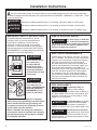 2
2
-
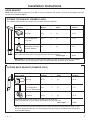 3
3
-
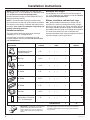 4
4
-
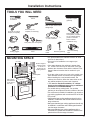 5
5
-
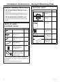 6
6
-
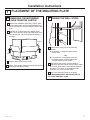 7
7
-
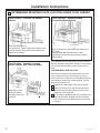 8
8
-
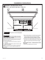 9
9
-
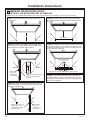 10
10
-
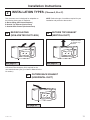 11
11
-
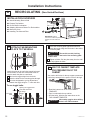 12
12
-
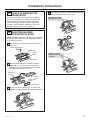 13
13
-
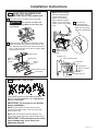 14
14
-
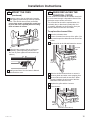 15
15
-
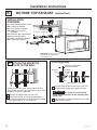 16
16
-
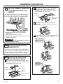 17
17
-
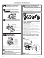 18
18
-
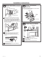 19
19
-
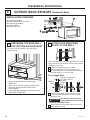 20
20
-
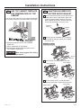 21
21
-
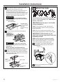 22
22
-
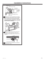 23
23
-
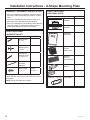 24
24
-
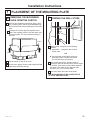 25
25
-
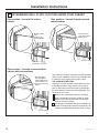 26
26
-
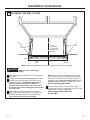 27
27
-
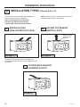 28
28
-
 29
29
-
 30
30
-
 31
31
-
 32
32
-
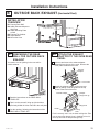 33
33
-
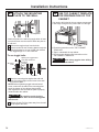 34
34
-
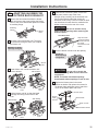 35
35
-
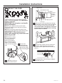 36
36
-
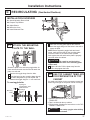 37
37
-
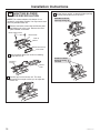 38
38
-
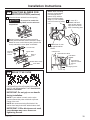 39
39
-
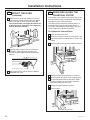 40
40
-
 41
41
-
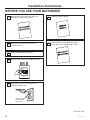 42
42
-
 43
43
-
 44
44
-
 45
45
-
 46
46
-
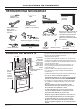 47
47
-
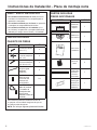 48
48
-
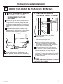 49
49
-
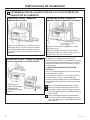 50
50
-
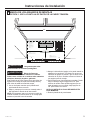 51
51
-
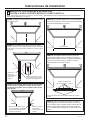 52
52
-
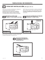 53
53
-
 54
54
-
 55
55
-
 56
56
-
 57
57
-
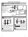 58
58
-
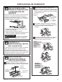 59
59
-
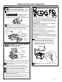 60
60
-
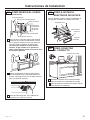 61
61
-
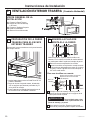 62
62
-
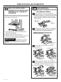 63
63
-
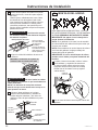 64
64
-
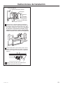 65
65
-
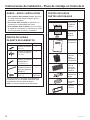 66
66
-
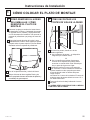 67
67
-
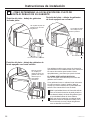 68
68
-
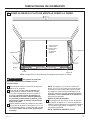 69
69
-
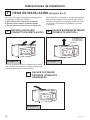 70
70
-
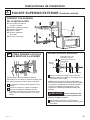 71
71
-
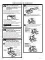 72
72
-
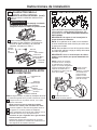 73
73
-
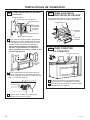 74
74
-
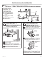 75
75
-
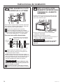 76
76
-
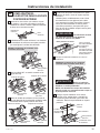 77
77
-
 78
78
-
 79
79
-
 80
80
-
 81
81
-
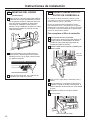 82
82
-
 83
83
-
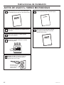 84
84


GE JVM3162RJSS Guía de instalación
- Categoría
- Microondas
- Tipo
- Guía de instalación
- Este manual también es adecuado para
en otros idiomas
- English: GE JVM3162RJSS Installation guide
Artículos relacionados
Otros documentos
-
GE Profile PVM9225SRSS Guía de instalación
-
Yes DMO30U970SS Guía de instalación
-
Dacor DMO30U970S Guía de instalación
-
Kenmore Pro 89393 Guía de instalación
-
Frigidaire FGMV176NTW Guía de instalación
-
Frigidaire FGBM19WNVF Guía de instalación
-
Frigidaire FGBM15WCVF Guía de instalación
-
Samsung ME11A7710DS Guía de instalación