Sanus LMT1 Manual de usuario
- Categoría
- Soportes de pared para panel plano
- Tipo
- Manual de usuario
Este manual también es adecuado para

Para Español ver página 14
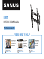
LMT1
INSTRUCTION MANUAL
Recommended placement
Our US-based
install experts
are standing
by to help.
Call us at:
1-855-734-7805
Get it right the
first time.
HeightFinder
™
shows you
where to drill.
Check it out at:
SANUS.com/2850
Want to watch a
video that shows
how easy this DIY
project will be?
Watch it now at:
SANUS.com/2845
WE’RE HERE TO HELP

2
80 lbs.
(36.3 kg)
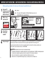
IMPORTANT SAFETY INSTRUCTIONS – SAVE THESE INSTRUCTIONS – PLEASE READ ENTIRE MANUAL PRIOR TO USE
Before getting started, let’s make sure this mount is perfect for you!
No
—
Perfect!
Yes
—
This mount is NOT compatible. Visit MountFinder.Sanus.com or call
1-855-734-7805 to find a compatible mount.
Please read through these instructions completely to be sure you’re comfortable with this easy install process.
Also check your TV owner’s manual to see if there are any special requirements for mounting your TV.
If you do not understand these instructions or have doubts about the safety of the installation, assembly or use
of this product, contact Customer Service at
1-855-734-7805.
Do you have
all the tools
needed?
1
2
3
4
What is your
wall made of?
Ready to begin?
Does your TV
(including accessories)
weigh more than
80 lbs. (36.3 kg)?
CAUTION:
DO NOT install
into drywall alone
Unsure?
Drywall with
wood studs?
Solid concrete or
concrete block?
Call Customer Service: 1-855-734-7805
Perfect!
CAUTION: Avoid potential personal injuries and property damage!
● This product is designed for use in wood stud, solid concrete, and concrete block walls - DO NOT install into drywall alone
● The wall must be capable of supporting five times the weight of the TV and mount combined
● Do not use this product for any purpose not explicitly specified by manufacturer
● Manufacturer is not responsible for damage or injury caused by incorrect assembly or use
Wood Stud Install
Concrete Install
Awl
Pencil Level
Stud Finder
Screwdriver
Tape
Measure
7/32 in.
(5.5 mm)
Wood
Drill Bit
Electric
Drill
Hammer
1/2 in.
(13 mm)
Socket
Wrench
Drill Bit
3/8 in.
(10 mm)
Concrete
Concrete Installation kit required (not included)

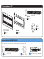
3
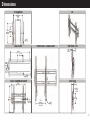
Dimensions
7.87in
200mm
MIN
0.35in
8.8mm
15.75in
400mm
MAX
7.87in
200mm
MIN
15.75in
400mm
MAX
4.75in
120.7mm
15.42in
391.7mm
2.93in
74.4mm
3.91in
99.4mm
0.33in
8.4mm
17.78in
451.6mm
16.93in
430mm
0.38in
9.7mm
OFFSET
7.87in
200mm
LATERAL SHIFT
AT 200 VESA
0.35in
8.8mm
6.50in
165.2mm
2.04in
51.8mm
LEVEL
ADJUST
SCREW
5deg
TIL
UP
10deg
TILT
DOWN
TV INTERFACE
WALL PLATE
FRONT VIEW - LATERAL SHIFT
3-D
SIDE VIEW - TILT
SIDE VIEW
FULLY ASSEMBLED MOUNT
Before getting started, let’s make sure this mount is perfect for you!

4
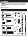
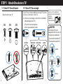
Parts and Hardware
WARNING: This product contains small items that could be a choking hazard if swallowed. Before starting assembly, verify all parts
are included and undamaged. If any parts are missing or damaged, do not return the damaged item to your dealer; contact Customer Service.
Never use damaged parts!
NOTE: Not all hardware included will be used.
STEP 1 Parts and Hardware
M6 x 12mm
M6 x 35mm
M6 x 20mm
M4 x 12mm
M4 x 35mm
M8 x 16mm M8 x 35mm
M8 x 25mm M8 x 50mm
TV Bracket
TV Screws
(qty. 4 each)
[Only one size fits your TV]
Washers
Spacer
[If necessary]
03
02
01
M6/M8
M4
M4/M6/M8
22 mm
M4/M6/M8
2.5 mm
M4
M6
M8
(qty. 1)
04
(qty. 1)
05
(qty. 4)
(qty. 4)

5
Wall Plate Template
Wall Plate
Concrete Installation Kit CMK1 (NOT INCLUDED)
Parts and Hardware for STEP 2
5/16 x 2¾ in.
.695 x .350 x .075 in.
5/16 x 2¾ in.
.695 x .350 x .075 in.
5/16 x 2¾ in.
.695 x .350 x .075 in.
5/16 in.
5/16 x 2 ¾ in.
Contact Customer Service to inquire about the CMK1 Concrete Installation Kit.
Fischer UX 10 x 60R Anchor
M4/M5 M6/M8
M4 x 12mm
M8 x 16mm
M8 x 20mm
M4 x 35mm
M8 x 35mm
M6 x 12mm
M6 x 35mm
M6 x 20mm
⁄ x 2 ⁄ in.
M5 x 12mm
M5 x 35mm
⁄ in.
Lag Bolt
Washer
09
5/16 x 2¾ in.
.695 x .350 x .075 in.
5/16 x 2 ¾ in.
08
5/16 in.
(qty. 1)
06
(qty. 1)
07
(qty. 2)
(qty. 2)
C1
(qty. 3)
C2
(qty. 3)
C3
(qty. 3)

6
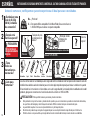
STEP 1 Attach Brackets to TV
FLAT BACK ROUND BACK CABLESINSET HOLES
1-1 Select TV
Screw Diameter
1-2 Select TV
Screw Length
a
b
If your TV has a flat back AND you want your TV closer to
the wall, use the shorter screws (a).
Use the spacers and longer screws (b) to accommodate:
● Round/irregular back TVs
● TVs with inset mounting holes
● Extra space needed for cables
Too Short
Too Long
CAUTION:
Verify adequate thread
engagement with the screw or
screw/spacer combination.
- Too short will not hold the TV.
- Too long will damage the TV.
Correct
M4
M6 M8
Only one size fits your TV.
If your TV included inset
spacers or wall mount adapters,
use them
UNDER the
mount hardware.

7
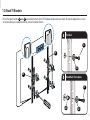
STEP 1 Attach Brackets to TV
1-3 Attach TV Brackets
Ensure that your brackets
04
and
05
are level on the back of the TV. Standard configurations are shown. For special applications, or if you
are unsure about your hardware selection, contact Customer Service.
a
Flat Back
b
Round Back / Extra Space
03
02
02
01
01
04
05

8
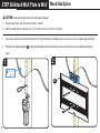
STEP 2A Attach Wall Plate to Wall
Wood Stud Option
CAUTION: Avoid potential personal injuries and property damage!
● Drywall covering the wall must not exceed 5/8 in. (16 mm)
● Minimum wood stud size: nominal 2 x 4 in. (51 x 102 mm) actual 1½ x 3½ in. (38 x 89 mm)
1. Locate your stud. Verify and mark the center of the stud by finding the stud edges using an awl, a thin nail, or an edge to edge stud finder.
2. Position the wall plate template
06
at your desired height and line up the holes with your stud center line. Level the template and tape in
place.
2
1
Max. 5/8 in.
(16 mm)
06

9
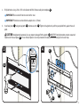
3. Drill pilot holes using a 7/32 in. (5.5 mm) diameter drill bit. Remove wall plate template
06
.
IMPORTANT: Be sure to drill into the center of the stud.
IMPORTANT: Pilot holes must be drilled to a depth of 3 in. (75 mm).
4. Install wall plate
07
using two lag bolts
08
and two washers
09
. Tighten the lag bolts only until they are pulled firmly against the wall
plate.
CAUTION: Avoid potential personal injury or property damage! Both lag bolts
08
MUST BE firmly tightened to prevent unwanted
movement of the wall plate
07
.
Ensure the wall plate is securely fastened to the wall before continuing on to the next step.
4
08
09
3
3 in.
(75 mm)
7/32 in.
(5.5 mm)
06
07

10
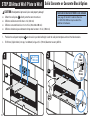
STEP 2B Attach Wall Plate to Wall
Solid Concrete or Concrete Block Option
2
1
002862.eps
Concrete Installation Kit CMK1 is not included
(see page 5) Contact Customer Service
at 1-855-734-7805 to inquire about the
additional hardware.
3/8 in.
(10 mm)
3 in.
(75 mm)
Min.
4 ¾ in.
(120.6 mm)
CAUTION: Avoid potential personal injuries and property damage!
● Mount the wall plate
07
directly onto the concrete surface
● Minimum solid concrete thickness: 8 in. (203 mm)
● Minimum concrete block size: 8 x 8 x 16 in. (203 x 203 x 406 mm)
● Minimum horizontal space between the top two fasteners: 4 ¾ in. (120.6 mm)
1. Position the wall plate template
06
on the wall at your desired height. Level the wall plate template and mark the hole locations.
2. Drill three (3) pilot holes (2 on top, 1 on bottom) using a 3/8 in. (10 mm) diameter masonry drill bit.
06
06

11
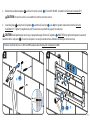
Solid Concrete or Concrete Block Option
43
*
*
3. Remove the wall plate template
06
and insert three (3) anchors
C3
(Fischer UX 10 x 60R - included in the Concrete Installation Kit*).
CAUTION: Be sure the anchors are seated flush with the concrete surface.
4. Install wall plate
07
using three (3) lag bolts
C1
and three (3) washers
C2
(use only the lag bolts and washers from the Concrete
Installation Kit*). Tighten the lag bolts only until the washers are pulled firmly against the wall plate.
CAUTION: Avoid potential personal injury or property damage! All three (3) lag bolts
C1
MUST BE firmly tightened to prevent unwanted
movement of the wall plate
07
.
Ensure the wall plate is securely fastened to the wall before continuing on to the next step.
*
Contact Customer Service at 1-855-734-7805 to inquire about the Concrete Installation Kit CMK1.
07
C3
C1
C2

12
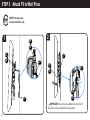
STEP 3 Attach TV to Wall Plate
HEAVY! You may need
assistance with this step.
IMPORTANT: You will hear an audible click when the TV
bracket is securely fastened to the wall plate.
07
07
07
07
04
05
04
05
04
05
04
05
2
1

13
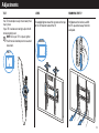
Adjustments
Pull down on the latches and lift
the TV up and out away from the
wall plate.
TILT
LEVEL
If needed, tighten one of the screws on the top
of the TV bracket to level the TV.
TILT REMOVING THE TVLEVEL
Your TV should adjust easily when moved, then
stay in place.
If your TV is too loose or too tight, adjust the tilt
tension knob by hand.
NOTE: Once your TV is in place, tighten
the tilt tension knob to prevent unwanted
movement.

14
36.3 kg
(80 lbs.)
Antes de comenzar, verifiquemos que este soporte sea el ideal para sus necesidades.
INSTRUCCIONES DE SEGURIDAD IMPORTANTES. CONSÉRVELAS. LEA TODO EL MANUAL ANTES DE UTILIZAR ESTE PRODUCTO.
ESPAÑOL
5,5 mm
(7/32'')
Madera
10 mm
(3/8'')
Hormigón
No
—
¡Perfecto!
Sí
—
Este soporte NO es compatible. Visite MountFinder.Sanus.com o llame al
1-855-734-7805 para encontrar un soporte compatible.
¿Su televisor pesa
más de 36.3 kg
(80 lb), incluidos
los accesorios?
Lea estas instrucciones en su totalidad para estar seguro de sentirse cómodo con este fácil proceso de instalación. Consulte
también el manual del usuario de su televisor para ver si existe algún requisito especial para instalar su televisor en la pared.
Si no entiende las instrucciones o si tiene dudas acerca de la seguridad de la instalación, del ensamblado o del uso del
producto, póngase en contacto con el servicio de atención al cliente al 1-855-734-7805.
¿Tiene
todas las
herramientas
necesarias?
1
2
3
4
¿De qué está
hecha su pared?
¿No está
seguro?
¿Hormigón sólido
o bloques de
cemento?
¿Listo para
comenzar?
13 mm
(1/2”)
¿Tabiques de yeso
con montantes de
madera?
Llame al 1-855-734-7805
¡Perfecto!
El Kit de instalación en hormigón no está incluido
DestornilladorCinta métrica Broca Broca
Taladro
eléctrico MartilloLlave de tubo
PRECAUCIÓN: Evite posibles lesiones personales y daños materiales.
● Este producto incluye instrucciones y elementos de sujeción para su instalación en paredes con montantes de madera,
en superficies de hormigón y sobre bloques de cemento. NO lo instale en tabiques únicamente de yeso.
● La pared debe soportar cinco veces el peso del televisor y del soporte juntos.
● No utilice este producto para ningún otro propósito que no sea el explícitamente especificado por el fabricante.
● El fabricante no se responsabiliza por ningún daño o lesión resultante del montaje incorrecto o de uso indebido.
PunzónLápiz Nivel
Localizador
de montantes
PRECAUCIÓN:
NO lo instale en
tabiques únicamente
de yeso
Paredes con
montantes de madera
paredes con de
hormigón

15
ESPAÑOL
NOTA: No todos los elementos de sujeción incluidos deberán utilizarse.
ADVERTENCIA: Este producto contiene piezas pequeñas que, si fuesen tragadas, podrían producir asfixia.
Antes de iniciar el ensamblaje, compruebe que todas las piezas estén incluidas y en buenas condiciones. Si faltan piezas o alguna está dañada,
no devuelva el artículo al distribuidor; póngase en contacto con el servicio de atención al cliente. Nunca utilice piezas deterioradas.
Asegúrese de que las placas de sujeción
04
y
05
queden niveladas en la parte posterior del televisor. Si necesita más espacio para cables,
concavidades o protuberancias, use los espaciadores (consulte la opción para dorso irregular en la siguiente página).
IMPORTANTE: Luego de fijar las placas de sujeción, ajuste las correas para nivelarlas con la parte inferior del televisor.
Piezas y elementos de sujeción suministrados
PASO 1 Colocar la placa de sujeción en el televisor
Dimensiones
Ver página 3
Ver página 4
Ver página 6
1-1 Seleccione el diámetro
de los tornillos para el televisor
1-2 Seleccione la longitud
de los tornillos para el televisor
1-3 Fije los soportes para televisor
Enrosque manualmente los tornillos en los encastres roscados del dorso del televisor a fin de determinar qué diámetro de tornillos (M4, M6 o M8) utilizar.
PRECAUCIÓN: Verifique que el tornillo o la combinación de tornillo y separador enrosquen correctamente. Si el tornillo es demasiado corto no sostendrá el
televisor y, si es demasiado largo, dañará el televisor.
Si el dorso del televisor es plano Y usted desea que el televisor quede más cerca de la pared, utilice los tornillos cortos (a).
Utilice los separadores y los tornillos largos (b) para: televisores con dorso irregular o redondeado, televisores con orificios de montaje intercalados o en el caso
de necesitar un espacio adicional para cables.
Si su televisor incluye espaciadores empotrados o adaptadores para soportes de pared, úselos BAJO el hardware de montaje.

16
ESPAÑOL
PRECAUCIÓN: Evite posibles lesiones personales y daños materiales.
● El yeso que recubre la pared no debe exceder los 16 mm (5/8 pulgada).
● Tamaño mínimo del montante de madera: común 51 mm x 102 mm (2 x 4 pulgadas) (nominal 38 mm x 89 mm [1½ x 3½ pulgadas])
1. Localice un montante. Busque los bordes del montante y marque el centro con un punzón o un clavo delgado, o bien utilice un detector de
bordes de montantes.
2. Ubique la plantilla de placa mural
06
a la altura deseada y alinee los orificios con la línea central de los montantes. Nivele la plantilla y fíjela
con cinta adhesiva en el lugar.
3. Realice los orificios guía con una mecha de 5,5 mm (7/32”) de diámetro. Retire la plantilla de la placa mural
06
.
IMPORTANTE: Asegúrese de perforar el centro del montante.
IMPORTANTE: Los orificios guía deben realizarse hasta una profundidad de 75 mm (3’’).
4. Instale el módulo de la placa mural
07
usando dos tornillos tirafondo
08
y dos arandelas
09
. Ajuste los tornillos tirafondo solamente
hasta que queden firmes contra la placa mural.
PRECAUCIÓN: El uso indebido podría reducir la capacidad de retención de los tornillos. NO ajuste en exceso los tornillos tirafondo.
PRECAUCIÓN: Evite posibles lesiones personales y daños materiales.
● Instale la placa mural
07
directamente sobre la superficie de hormigón.
● Espesor mínimo del hormigón: 203 mm (8 pulgadas)
● Tamaño mínimo del bloque de cemento: 203 x 203 x 406 mm (8 x 8 x 16 pulgadas)
● Espacio horizontal mínimo entre los dos sujetadores superiores: 120,6 mm (4 3/4 pulgadas)
1. Coloque la plantilla de la placa mural
06
en la pared a la altura que desee.
Nivele la plantilla de la placa mural y marque la ubicación de los orificios.
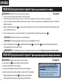
PASO 2A Fijar la placa mural a la pared - Opción para montantes de madera
PASO 2B Fijar la placa mural a la pared -
Opción para hormigón sólido o bloques de cemento
Ver página 8
Ver página 10
El Kit de instalación en hormigón CMK1 no
está incluido (Ver página 5) Comuníquese
con el servicio de atención al cliente al 1-855-
734-7805 para solicitar que le enviemos los
elementos de sujeción adicionales.

17
ESPAÑOL
¡ELEMENTO PESADO! Es posible que necesite ayuda
en este paso.
IMPORTANTE: Oirá un clic cuando la placa de sujeción del
televisor esté bien sujeta a la placa mural.
PASO 3 Instalar el televisor en la pared
Ajustes
Ver página 12
Ver página 13
AJUSTE DE LA INCLINACIÓN: Afloje la perilla
que se encuentra en la placa de sujeción del
televisor a fin de ajustar la inclinación de su
televisor. Ajuste la perilla cuando su televisor
tenga la inclinación deseada.
RETIRAR EL TELEVISOR: Jale hacia
abajo de las correas, levante el
televisor y retírelo de la placa mural.
AJUSTE DE LA NIVELACIÓN: Si es necesario,
ajuste uno de los tornillos de la parte superior
de la placa de sujeción del televisor para nivelar
el televisor.
PASO 2A Fijar la placa mural a la pared - Opción para montantes de madera
PASO 2B Fijar la placa mural a la pared -
Opción para hormigón sólido o bloques de cemento
2. Realice los orificios guía con una mecha para mampostería de 10 mm (3/8’’) de diámetro.
IMPORTANTE: Los orificios guía deben realizarse hasta una profundidad de 75 mm (3’’). Nunca perfore el cemento que une los bloques.
3. Retire la plantilla de la placa mural
06
e introduzca tres anclajes
C3
(Fischer UX 10 x 60R - incluidos en el Kit de instalación en hormigón CMK1*).
PRECAUCIÓN: Cerciórese de que los anclajes queden nivelados respecto de la superficie de hormigón.
4. Instale el módulo de la placa mural
07
usando tres tornillos tirafondo
C1
y tres arandelas
C2
(utilizar únicamente los tornillos tirafondo y las
arandelas del Kit de instalación en hormigón CMK1*). Ajuste los tornillos tirafondo solamente hasta que queden firmes contra la placa mural.
PRECAUCIÓN: El uso indebido podría reducir la capacidad de retención de los tornillos
C1
. NO ajuste en exceso los tornillos tirafondo.
*
Comuníquese con el servicio de atención al cliente al 1-855-734-7805 para solicitar que le enviemos el Kit de instalación en hormigón.

18

19

6901-602398 00
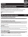
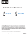
SAN.US/2845 1-855-734-7805
Watch the installation video or call our Customer Care team for help
Legrand AV Inc. and its aliated corporations and subsidiaries (collectively, “Legrand”), intend to make this manual accurate and complete. However, Legrand
makes no claim that the information contained herein covers all details, conditions, or variations. Nor does it provide for every possible contingency in connection
with the installation or use of this product. The information contained in this document is subject to change without notice or obligation of any kind. Legrand makes
no representation of warranty, expressed or implied, regarding the information contained herein. Legrand assumes no responsibility for accuracy, completeness or
suciency of the information contained in this document.
©2019 Legrand AV Inc. All rights reserved. Sanus is a division of Legrand. SANUS and the SANUS logo are registered trademarks.
Legrand AV Inc. • 6436 City West Parkway • Eden Prairie, MN 55344 USA
-
 1
1
-
 2
2
-
 3
3
-
 4
4
-
 5
5
-
 6
6
-
 7
7
-
 8
8
-
 9
9
-
 10
10
-
 11
11
-
 12
12
-
 13
13
-
 14
14
-
 15
15
-
 16
16
-
 17
17
-
 18
18
-
 19
19
-
 20
20


Sanus LMT1 Manual de usuario
- Categoría
- Soportes de pared para panel plano
- Tipo
- Manual de usuario
- Este manual también es adecuado para
en otros idiomas
- English: Sanus LMT1 User manual
Artículos relacionados
-
Sanus LLF122 Manual de usuario
-
-
-
Sanus LLT1 Guía de instalación
-
-
-
-
-
-

