
LLL1
Instruction Manual
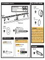
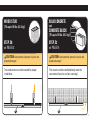
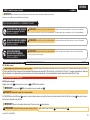
Recommended placement
Our US-based
install experts
are standing
by to help.
Call us at:
1-855-734-7805
Get it right the
first time.
HeightFinder
™
shows you
where to drill.
Check it out at:
SANUS.com/2850
Want to watch a
video that shows
how easy this DIY
project will be?
Watch it now at:
SANUS.com/2839
WE’RE HERE TO HELP
Para Español ver página 22

2
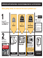
IMPORTANT SAFETY INSTRUCTIONS – PLEASE READ ENTIRE MANUAL PRIOR TO USE – SAVE THESE INSTRUCTIONS
...No?
=
...Ye s ?
=
This mount
is NOT compatible.
Visit:
MountFinder.Sanus.com
or call:
1-855-734-7805 to find a
compatible mount.
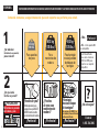
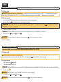
Before getting started, let’s make sure this mount is perfect for you!
1
2
What is your
wall made of?
Wood studs?
Drywall?
Perfect! Perfect!*
Perfect!
Perfect!
Does your TV
(including accessories)
weigh MORE than ...
Solid concrete or
concrete block?
Unsure?
Call Customer Service:
1-855-734-7805
for
Solid concrete or
concrete block?
for
Wood studs
for
Drywall
135 lbs.
(61.2 kg)
135 lbs.
(61.2 kg)
100 lbs.
(45.3 kg)
CAUTION:
DO NOT install into
plaster & lath walls
Metal Lath
Wood Lath
Rough Plaster Surface
*Concrete kit is NOT
INCLUDED. Call customer
service for kit #CMK3.

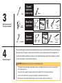
3
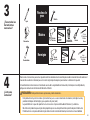
Please read through these instructions completely to be sure you’re comfortable with this easy install process.
Also check your TV owner’s manual to see if there are any special requirements for mounting your TV.
If you do not understand these instructions or have doubts about the safety of the installation, assembly
or use of this product, contact Customer Service.
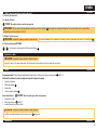
Do you have all of
the tools needed?
3
4
CAUTION: Avoid potential personal injuries and property damage!
● This product includes directions and hardware for use with wood studs, solid concrete and concrete block
walls,
and drywall only.
● The wall must be capable of supporting five times the weight of the TV and mount combined.
● Do not use this product for any purpose not explicitly specified by manufacturer.
● Manufacturer is not responsible for damage or injury caused by incorrect assembly or use.
Ready to begin?
Included
Included
1/8 in. (3.2 mm)
Wood
5/16 in. (8 mm)
Masonry
Screwdriver
Tape
Measure
Stud Finder
Hammer
Hammer
Awl
Pencil
Drill Bit
Drill Bit
Electric
Drill
Electric
Drill
Square Driver Bit
Square Driver Bit
Drywall
Applications
NO DRILL OPTION
Wood Stud
Applications
Concrete
Applications

4
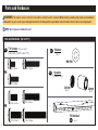
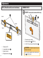
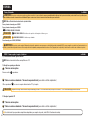
Parts and Hardware [for STEP 1]
Parts and Hardware
WARNING: This product contains small items that could be a choking hazard if swallowed. Before starting assembly, verify all parts are included and
undamaged. If any parts are missing or damaged, do not return the damaged item to your dealer; contact Customer Service. Never use damaged parts!
NOTE: Not all hardware included will be used.
01
03
02
04
M8 x 50mm
M8 x 25mm
M8 x 35mm
M8 x 16mm
M6 x 12mm
M6 x 20mm
M6 x 35mm
TV Screws (qty. 2 each)
[Only one size fits your TV]
Washer
Spacers
[If necessary]
TV Bracket
qty.1
qty.2
qty.4
M6
2.5mm
M8/M6
M8
qty.2
22mm

5
#10 x 2 ½ in.
Fischer UX8 x 50R
14 ga. x 1 ¼ in.
For CONCRETE installations ONLY For DRYWALL installations ONLY
Parts and Hardware [for STEP 2]
Parts [for STEP 3] (OPTIONAL)
Tools Included
*
WARNING: This product contains
a magnet. If an implanted medical device
such as a pacemaker or implantable
cardioverter defibrillator (ICD) is in use,
magnetic fields may aect the operation
of those devices, resulting in serious injury
or death. If you have an implanted medical
device, keep at least 13 cm (5 in.) between
your device and the magnet. Please
consult with your physician or medical
professional prior to using this product.
C1
Wall Plate
Concrete Anchor
Nail
Washer
(Wood Screw)
Stando
*
(Magnetic Leveling Foot)
Disc
(Adhesive backed)
Wood Screw (Wall Plate)
FOR STEP 2B and STEP 2C ONLY
Driver Bit
(Square)
CAUTION: FOR STEP 2C ONLY:
Do not use in drywall or wood.
CAUTION: FOR STEP 2A ONLY:
Do not use in concrete or plaster & lath.
Built-in Level
NOTE: These anchors are NOT INCLUDED.
Contact Customer Service for anchor kit #CMK3.
05
qty.1
06
qty.2
07
qty.2
08
qty.32
09
qty.2
10
qty.2
11
qty.1
qty.2
Locking Mechanism
KEEP IN THE LOCKED POSITION
until instructed.
UNLOCKED
LOCKED

6
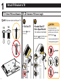
1
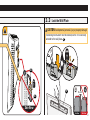
1 .1 Select TV Screw Diameter 1.2 Determine TV Screw Length
NOTE: Only one screw size fits your TV.
• Flat Back TV • Rounded Back TV
• Extra Space Needed
[for cables or inset holes]
A
Too Short
Too Long
CAUTION:
Verify adequate thread
engagement with your screw/
washer/spacer combination
AND TV Bracket
04
.
- Too short will not hold the TV.
- Too long will damage the TV.
Correct
B
spacers
03
are not
necessary.
Rounded
Back
Flat Back
Cable
Interference
Inset
Holes
Use spacers
03
to create extra space
between the TV and TV bracket.
03
03
Attach TV Bracket to TV
M6
M8
04
04

7
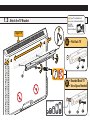
Attach TV Bracket to TV
1.3 Attach the TV Bracket
03
01
02
02
01
• Flat Back TV
A
B
• Rounded Back TV
• Extra Space Needed
Top of TV
Spacer Options
04
If your TV included inset
spacers or wall mount adapters,
use them
UNDER the
mount hardware.

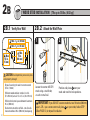
8
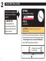
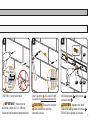
2
IMPORTANT:
You must determine
your wall construction to
correctly secure the wall
plate to the wall.
Attach Wall Plate to Wall
STEP 2A
on PAGE 10
DRYWALL
[TVs up to 100 lbs. (45.3 kg)]
CAUTION: Avoid potential personal injuries and
property damage!
Wood stud(s) are okay
to nail through
CAUTION:
DO NOT install into plaster & lath walls
Follow the corresponding
step for your installation
method.
● DO NOT mount to patched areas/drywall seams /uneven walls
● Drywall must be of sound construction with no water damage
If water damage ever occurs - remove the TV immediately
● Your TV MUST be centered on the wall plate
05

9
STEP 2B
on PAGE 12
WOOD STUD
[TVs up to 135 lbs. (61.2 kg)]
Two stud centers must be located for proper
installation.
CAUTION: Avoid potential personal injuries and
property damage!
Attach Wall Plate to Wall
STEP 2C
on PAGE 14
SOLID CONCRETE
and
CONCRETE BLOCK
[TVs up to 135 lbs. (61.2 kg)]
CAUTION: Avoid potential personal injuries and
property damage!
The mount must be installed directly onto the
concrete surface (no surface covering).
05 05

10
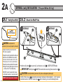
2A
CAUTION: Avoid potential
personal injuries and property damage!
●Drywall covering must be 3/8 in.
(9.5 mm) or greater
●Drywall must be mounted on studs, no
more than 24 in. (609 mm) on center,
[minimum stud size: nominal 2 x 4 in. (51 x
102 mm) actual 1½ x 3½ in. (38 x 89 mm)]
●Drywall must be sound with no water
damage. If water damage ever occurs
— remove the TV immediately
●DO NOT mount to patched areas,
on drywall seams or uneven walls
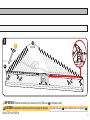
CAUTION: Avoid potential personal injuries and property damage!
If ANY of the 32 nails
08
encounter excessive resistance (metal object) - STOP and call
customer service. DO NOT reuse nails
08
after removing, or use store-bought nails.
2A.1 Verify Your Wall 2A. 2 Attach the Wall Plate
DRYWALL (only) INSTALLATION [TVs up to 100 lbs. (45.3 kg)]
Min.
3/8 in. (9.5 mm)
1 2
OUTER HOLE
OUTER HOLE
08
08
Position wall plate
05
on your wall, and secure a nail
08
in BOTH OUTER holes.
IMPORTANT: Wall plate
05
MUST be level when securing the second nail
08
.
● DO NOT install into plaster & lath walls
05
05
05

11
IMPORTANT: Alternate installing the remaining thirty (30) nails
08
from side to side.
CAUTION: Avoid potential personal injuries and property damage! Thirty-two (32)
nails
08
total, must be used in wall plate
05
.
Go to STEP 3 on PAGE 16.
3
(qty. 30)
08
05

12
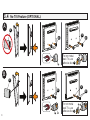
2B
CAUTION: Avoid potential personal injuries
and property damage!
● Drywall covering the wall must not exceed
5/8 in. (16 mm)
● Minimum wood stud size: nominal 2 x 4 in.
(51 x 102 mm) actual 1½ x 3 ½ in. (38 x 89 mm)
● Minimum horizontal space between fasteners:
16 in. (406 mm)
● Stud centers must be verified – not all walls
have conventional 16 in. (406 mm) stud spacing
2 B.1 Verify Your Wall
WOOD STUD INSTALLATION [TVs up to 135 lbs. (61.2 kg)]
1
Max.
5/8 in.
(16 mm)
Min.
16 in.
(406 mm)
Min. 1
½
in. (38 mm)
Min. 3
½
in. (89 mm)
2B.2 Attach the Wall Plate
2
Locate the center of BOTH
studs using a stud finder,
an awl or small nail.
Position wall plate
05
over your
studs and mark the hole positions.
IMPORTANT: If you DO NOT have two studs that are 16 inches (406 mm)
apart – OR – you cannot center wall plate
05
on your studs, follow STEP
2B on PAGE 12, for drywall installation.
05

13
3 4
CAUTION: Improper use could reduce the holding power
of screws
07
. DO NOT over-tighten the screws.
Go to STEP 3 on PAGE 16.
0711
05
06
IMPORTANT: Holes must be drilled to a depth
of 2 ½ in. (63 mm) — in the center of the stud.
Drill 1/8 in. (3.2 mm) pilot holes.
Install wall plate
05
with screws
07
and washers
06
.
2 ½ in. (63 mm)
1/8 in.
(3.2 mm)

14
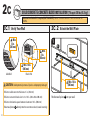
2C
2C.1 Verify Your Wall
SOLID CONCRETE / CONCRETE BLOCK INSTALLATION [TVs up to 135 lbs. (61.2 kg)]
CAUTION: Avoid potential personal injuries and property damage!
●Minimum solid concrete thickness: 8 in. (203 mm)
●Minimum concrete block size: 8 x 8 x 16 in. (203 x 203 x 406 mm)
●Minimum horizontal space between fasteners: 16 in. (406 mm)
●Mount wall plate
05
directly onto the concrete surface (no wall covering)
2C.2 Attach the Wall Plate
1
Min. 16 in.
(406 mm)
Min.
8 in.
(203 mm)
Min. 16 in.
(406 mm)
Min.
8 in.
(203 mm)
Position wall plate
05
on your wall.
Concrete Installation Kit is required [NOT INCLUDED]
Contact Customer Service 1-855-734-7805 for kit
#CMK3
.
Solid Wall Block Wall
05

15
SOLID CONCRETE / CONCRETE BLOCK INSTALLATION [TVs up to 135 lbs. (61.2 kg)]
IMPORTANT: Holes must be
drilled to a depth of 2¾ in. (70 mm).
Never drill into the mortar between blocks.
CAUTION: Be sure the anchors
C1
are seated flush with the
concrete surface.
CAUTION: Improper use could
reduce the holding power of screws
07
.
DO NOT over-tighten the screws.
002862.eps
5/16 in.
(8 mm)
2¾ in. (70 mm)
11 07
2 3 4
06
Drill 5/16 in. (8 mm) pilot holes.
Install wall plate
05
with screws
07
and washers
06
.
Insert anchors
C1
(Fischer UX8 x 50R –
included in the Concrete Installation Kit)
C1
05

16
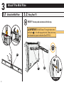
3
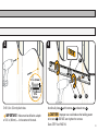
3 .1 Unlock the Wall Plate 3.2 Hang Your TV
HEAVY! You may need assistance with this step.
Side View
Attach TV to Wall Plate
IMPORTANT: DO NOT lower TV straight down onto
wall plate
05
-- this will engage the lock. Safety latch must
be released for proper installation (See STEP 3.1).
05
05
04
04
05

17
Side View
Attach TV to Wall Plate
3.3 Lock the Wall Plate
CAUTION: Avoid potential personal injury or property damage!
The locking mechanism must be locked, so the TV is securely
fastened to the wall plate
05
.
Side View Side View
Button
04
05
05

18
3.4 No Tilt Feature (OPTIONAL)
A
B
For non-metal
back TVs, use
adhesive disc
10
.
For non-metal
back TVs, use
adhesive disc
10
.
03
03
09 09
09
09
09
09
09
10
10
09
09
09
10
10

19
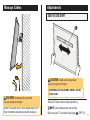
Manage Cables Adjustments
SIDE-TO-SIDE SHIFT
Slide the TV side to side to adjust positioning.
NOTE: Safety stops prevent over-shifting.
Make sure your TV is locked to wall plate
05
(STEP 3.3).
CAUTION: Avoid potential personal
injury or property damage!
DO NOT force open your TV when adding cables. STOP
lifting the bottom outward when you feel resistance.
CAUTION: Avoid potential personal
injury or property damage!
FOR DRYWALL INSTALLATIONS: DO NOT slide the
TV side-to-side.
05

20
REMOVE THE TV
1. Disconnect your cables.
2. Unlock wall plate
05
(STEP 3.1).
3. Lift the TV up and away from wall plate
05
.
CAUTION: Avoid potential personal injuries
and property damage!
DO NOT reuse this product after removing wall
plate
05
from the wall.
LEVEL [Wood Stud and Concrete Installations]
1. Remove the TV.
2. Loosen both screws
07
.
3. Adjust the level.
4. Retighten both screws
07
.
Loosen
Loosen
Tighten
Tighten
07
HEAVY! You may need assistance with this step.
Adjustments
05

21
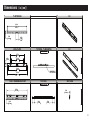
Dimensions
( in. [mm] )
24.61in
625mm
MAX
2.95in
75mm
MIN
1.54in
39.1mm
2.28in
57.9mm
16.00in
406.4mm
17.72in
450mm
23.62in
600mm
24.00in
609.6mm
2.84in
72.3mm
25.50in
647.7mm
1.18in
29.9mm
SIMULATED 60"
FLAT SCREEN TV
3.40in
86.4mm
3.40in
86.4mm
TV INTERFACE
WALL PLATE
TOP VIEW - TV MOUNTED
3-D
3-D
SIDE VIEW
TOP VIEW
FULLY ASSEMBLED MOUNT
WALL IS ON RIGHT
WALL IS ON RIGHT
WALL IS ON TOP
WALL IS ON TOP

22
*Se requiere el kit CMK3) [no
está incluido]. Llame al Servicio
de Atención al Cliente
INSTRUCCIONES IMPORTANTES DE SEGURIDAD: GUARDE ESTAS INSTRUCCIONES Y LEA TODO EL MANUAL ANTES DE UTILIZAR ESTE PRODUCTO.
ESPAÑOL
Antes de comenzar, asegurémonos de que este soporte sea perfecto para usted.
¿De qué está
hecha su pared?
¿Su televisor
(incluidos los accesorios)
pesa más de?
...No
=
...Sí
=
Este soporte NO
es compatible.
Visite MountFinder.
Sanus.com o llame al
1-855-734-7805 para
encontrar un soporte
compatible.
1
2
¿Paneles
de yeso con
montantes de
madera?
¿Paneles de yeso?
¡Perfecto! ¡Perfecto!*
¡Perfecto!
¡Perfecto!
¿Hormigón
macizo o bloque
de hormigón?
¿No está seguro?
Llame al
1-855-734-7805
Para hormigón
macizo/paredes
de bloques de
hormigón
Para
montantes de
madera
Para paneles
de yeso
61,2 kg
(135 lbs.)
61,2 kg
(135 lbs.)
45,3 kg
(100 lbs.
Método opcional para
instalaciones que NO SE
PUEDEN centrar sobre
dos montantes de madera.
PRECAUCIÓN:
NO instalar en paredes
de listones y yeso
Listón metálico
Listón de
madera
Superficie de yeso irregular

23
¿Tiene todas las
herramientas
necesarias?
¿Listo para
comenzar?
Revise estas instrucciones para estar seguro de sentirse cómodo con este sencillo proceso de instalación. Consulte además el
manual del usuario de su televisor para ver si existe algún requisito especial para montar su televisor en la pared.
Si no entiende las instrucciones o si tiene dudas acerca de la seguridad de la instalación, el montaje o el uso del producto,
póngase en contacto con el Servicio de Atención al Cliente.
3
4
PRECAUCIÓN: Evite posibles lesiones personales y daños materiales.
● Este producto incluye instrucciones y herramientas para su uso en montantes de madera, hormigón macizo y
paredes de bloques de hormigón y para paneles de yeso (solo).
● La pared debe ser capaz de soportar hasta cinco veces el peso combinado del televisor y la montura.
● No utilice este producto para ningún otro propósito que no sea el explícitamente especificado por el fabricante.
● El fabricante no se responsabiliza de ningún daño o lesión resultante del montaje incorrecto o el uso indebido.
Incluido
Paneles de
yeso
Hormigón
8 mm
(5/16 pulgadas)
Hormigón
Destornillador
Martillo
Martillo
Lápiz
Broca
Taladro
eléctrico
Broca de
desarmador
cuadrada
Incluido
Madera
3,2 mm
(1/8 pulgadas)
Madera
Cinta métrica
Localizador
de montantes
Punzón
Broca
Taladro
eléctrico
Broca de
desarmador
cuadrada

24
Si su televisor incluye espaciadores empotrados o adaptadores para soportes de pared, úselos BAJO el hardware de montaje.
ESPAÑOL
A
•
Televisor con dorso plano
A
•
Televisor con dorso plano
B
•
Televisor con dorso redondeado
•
Se necesita espacio adicional (para cables u orificios empotrados)
B
•
Televisor con dorso redondeado
•
Se necesita espacio adicional (para cables u orificios empotrados)
PASO 1 Cómo acoplar el soporte al televisor
1,1 Seleccione los tornillos para el televisor
1,2 Acople los soportes para televisor
PRECAUCIÓN: Verifique el enrosque del tornillo o del conjunto tornillo/espaciador.
–
Si es demasiado corto, no sujetará el televisor.
–
Si es demasiado largo, dañará el televisor.
Ver PÁGINA 6
ADVERTENCIA: Este producto contiene piezas pequeñas que podrían causar asfixia si se tragasen. Antes de comenzar a ensamblar la unidad, verifique que todas las piezas estén incluidas y en buen estado. En caso de que falten piezas o
alguna esté dañada, no devuelva el elemento defectuoso al distribuidor. Póngase en contacto con el servicio de atención al cliente. Nunca utilice piezas en mal estado.
Piezas y elementos de montaje para el PASO 1
Piezas y elementos de montaje para el PASO 2
Piezas de montaje para el PASO 3 (OPCIONAL)
NOTA: No se utilizarán todos los elementos de sujeción incluidos.
*
ADVERTENCIA: Este producto contiene un imán. Si utiliza un dispositivo médico implantado como un marcapasos o un desfibrilador automático implantable (DAI), los campos magnéticos pueden afectar el funcionamiento de esos
dispositivos, y causar heridas de gravedad o la muerte. Si tiene un dispositivo médico implantado, mantenga una distancia de al menos 13 cm (5 pulgadas) entre su dispositivo y el imán. Consulte a su médico antes de utilizar este producto.
Piezas y Elementos
Ver PÁGINA 4
1.3 Acople el soporte de TV
NOTA: Solo un tamaño de tornillo es compatible con su TV.
07
SOLO PARA EL PASO 2B Y EL PASO 2C
PRECAUCIÓN:
08
SOLO PARA EL PASO 2A: No utilizar sobre superficies de hormigón o de listones y yeso.
PRECAUCIÓN:
C1
SOLO PARA EL PASO 2C: No utilizar en yeso laminado
No se necesitan
03
separadores.
Utilice separadores
03
para crear un espacio adicional entre el TV y el soporte.

25
Piezas y elementos de montaje para el PASO 1
Piezas y elementos de montaje para el PASO 2
Piezas de montaje para el PASO 3 (OPCIONAL)
ESPAÑOL
PASO 2 Cómo fijar la placa a la pared
Ver PÁGINA 8
IMPORTANTE: Debe determinar cuál es la construcción de su pared para asegurar correctamente la placa mural a la pared.
Siga el paso correspondiente para la instalación de su placa mural.
PRECAUCIÓN: Evite posibles lesiones físicas y daños materiales. Para una instalación adecuada, deben localizarse los centros de los montantes.
PRECAUCIÓN: Evite posibles lesiones físicas y daños materiales. El soporte debe instalarse directamente en sobre la superficie de hormigón
(no en la superficie que recubre la pared).
PRECAUCIÓN: Evite posibles lesiones físicas y daños materiales. No instale el soporte en zonas parcheadas o en las uniones de los paneles de
yeso. Los paneles de yeso deben ser sólidos y no presentar humedades. Si en algún momento aparecen humedades, retire el televisor inmediatamente.
INSTALACIÓN EN MONTANTES DE MADERA
Para televisores de hasta 61,2 kg (135 lbs.)
PASO 2B en la PÁGINA 12
INSTALACIÓN EN HORMIGÓN
MACIZO Y BLOQUES DE HORMIGÓN
Para televisores de hasta 61,2 kg (135 lbs.)
PASO 2C en la PÁGINA 14
INSTALACIÓN EN PANELES DE YESO (SOLO)
Para televisores de hasta 45,3 kg (100 lbs.)
PASO 2A en la PÁGINA 10
Siga el paso correspondiente a su método de instalación.
PASO 2A Cómo fijar la placa a la pared
INSTALACIÓN EN PANELES DE YESO (solo)
2A,1 Verifique su pared
PRECAUCIÓN: Evite posibles lesiones físicas y daños materiales. • Los paneles de yeso que recubren la pared deben ser de 9.5 mm (3/8 pulg.) o más. • Los paneles de yeso deben instalarse sobre
montantes, con 406 mm (16 pulg.) de separación, [tamaño mínimo del montante de madera: nominal 51 x 102 mm (2 x 4 pulg.), real 38 x 89 mm (1½ x 3½ pulg.)]. • Los paneles de yeso deben ser sólidos y no
presentar humedades. Si en algún momento aparecen humedades, retire el televisor inmediatamente. • Espacio mínimo horizontal entre los elementos de sujeción: 305 mm (12 pulg.).
Ver PÁGINA 12
Vaya al PASO 3 en la PÁGINA 16.
2A,2 Fije la placa de pared
PRECAUCIÓN: Evite posibles lesiones físicas y daños materiales.
Si CUALQUIERA de los veinte (20) clavos
08
encuentra resistencia, deje de golpear con el martillo y llame al servicio de atención al cliente. NO reutilice los clavos
08
después de extraerlos
o utilice clavos comprados en una ferretería.
Coloque la placa mural
05
sobre la pared y clave un clavo
08
en AMBOS orificios exteriores.
IMPORTANTE: La placa mural
05
DEBE estar nivelada al clavar el segundo clavo
08
.
IMPORTANTE: Alterne la instalación de los dieciocho (18) clavos restantes
08
de un lado a otro.
PRECAUCIÓN: Evite posibles lesiones personales y daños materiales. Deben utilizarse veinte (20) clavos
08
en total en la placa mural
05
.
● NO instalar en paredes de listones y yeso

26
Se requiere el kit CMK3 [no está incluido]. Llame al Servicio de Atención al Cliente: 1-855-734-7805
ESPAÑOL
PASO 2C Cómo fijar la placa a la pared
Opción para hormigón macizo o bloque de hormigón
2C,1 Verifique su pared
2C,2 Fije la placa de pared
PRECAUCIÓN: Evite posibles lesiones físicas y daños materiales. • Grosor mínimo del hormigón macizo: 203 mm (8"). • Tamaño mínimo del bloque de hormigón: 203 x 203 x 406 mm (8 x 8 x 16").
• Espacio horizontal mínimo entre los elementos de sujeción: 406 mm (16"). • Instale la placa mural
05
directamente sobre la superficie de hormigón.
Ver PÁGINA 14
1. Coloque la placa mural
05
sobre la pared.
2. Taladre orificios piloto de 8 mm (5/16 pulg.).
IMPORTANTE
:
Los orificios DEBEN realizarse con una broca de 70 mm (2,75 pulgada) de diámetro hasta una profundidad de 8 mm (5/16 pulg.). Nunca taladre sobre el cemento entre los bloques.
3. Inserte los anclajes
C1
.
PRECAUCIÓN: Asegúrese de que los tacos estén asentados al mismo nivel de la superficie de hormigón.
4. Instale la placa mural
05
con tornillos
07
y arandelas
06
.
PRECAUCIÓN: El uso incorrecto podría reducir la capacidad de sujeción del perno tirafondo
07
. NO apriete excesivamente los pernos tirafondo.
PASO 2B Cómo fijar la placa a la pared
OPCIÓN PARA MONTANTES DE MADERA
2B,1 Verifique su pared
2B,2 Fije la placa de pared
PRECAUCIÓN: Evite posibles lesiones físicas y daños materiales. • La mampostería que cubre la pared no debe superar los 16 mm (5/8"). • Tamaño mínimo del montante de madera:
común 51 x 102 mm (2" x 4") nominal 38 x 89 mm (1½" x 3½"). • Espacio horizontal mínimo entre los elementos de sujeción: 406 mm (16"). • Debe verificarse el centro del montante.
PRECAUCIÓN: El uso incorrecto podría reducir la capacidad de sujeción del perno tirafondo
07
. NO apriete excesivamente los pernos tirafondo.
Vaya al PASO 3 en la PÁGINA 16.
Ver PÁGINA 10
1. Localice el centro de AMBOS montantes mediante un localizador de montantes, un punzón o un pequeño clavo.
2. Coloque la placa mural
05
sobre los montantes y marque las posiciones de los orificios.
3. Taladre orificios piloto de 3,2 mm (1/8 pulg.).
IMPORTANTE
:
Los orificios DEBEN realizarse con una broca de 63 mm (2,5 pulgada) de diámetro hasta una profundidad de 3,2 mm (1/8 pulg.).
4. Instale la placa mural
05
con tornillos
07
y arandelas
06
.
IMPORTANTE: Si NO tiene dos montantes con una separación de 406 mm (16 pulgadas) entre ellos – O – no puede centrar la placa mural
05
sobre los montantes, siga el PASO 2B
de la PÁGINA 12 para la instalación en yeso laminado.

27
ESPAÑOL
Para televisores sin dorso metálico, utilice la placa adhesiva
10
.
Desplazamiento lateral: Deslice el televisor horizontalmente. Asegúrese de que el televisor está fijado a la placa de pared
05
(PASO 3,3).
Nivelación [Para montantes de madera y hormigón macizo/paredes de bloques de hormigón]:
1. Cómo retirar el televisor.
2. Afloje ambos tornillos
07
.
3. Ajuste el nivel.
4. Vuelva a apretar los tornillos
07
.
Extracción del televisor:
1. Desconecte los cables.
2. Libere la placa de pared
05
(PASO 3,1).
3. Levante el televisor hacia arriba y retírelo.
PASO 3 Cómo fijar el televisor a la placa de pared
Ajustes
Dimensiones
Ver PÁGINA 21
Ver PÁGINA 16
3,1 Libere la placa de pared
3,2 Cuelgue el televisor
3,3 Bloquee la placa de pared
3,4 Opción antinclinación (OPCIONAL)
¡PESADO! Necesitará ayuda para realizar esta operación.
¡PESADO! Necesitará ayuda para realizar esta operación.
IMPORTANTE: NO baje el televisor dirigiéndolo directamente hacia la placa de pared
05
: esto enganchará la pestaña de bloqueo. Para una instalación correcta, el pestillo de
seguridad debe estar liberado (Véase PASO 3,1).
PRECAUCIÓN: Evite posibles lesiones personales o daños materiales. El pestillo de seguridad debe estar bloqueado, de modo que el televisor quede fijado con firmeza a la placa de pared
05
.
Ver PÁGINA 19
Ver PÁGINA 19
PRECAUCIÓN: Evite posibles lesiones personales o daños materiales.
PRECAUCIÓN: Evite posibles lesiones personales o daños materiales.
A
y
B
NO abra por la fuerza el TV cuando añada cables. Deje de levantar la parte inferior hacia fuera cuando note resistencia.
NO reutilice este producto después de retirar la placa mural
05
de la pared.
Organizar los cables

6901-602399 00
Legrand AV Inc. and its aliated corporations and subsidiaries (collectively, “Legrand”), intend to make this manual accurate and complete. However, Legrand makes no claim
that the information contained herein covers all details, conditions, or variations. Nor does it provide for every possible contingency in connection with the installation or use of
this product. The information contained in this document is subject to change without notice or obligation of any kind. Legrand makes no representation of warranty, expressed or
implied, regarding the information contained herein. Legrand assumes no responsibility for accuracy, completeness or suciency of the information contained in this document.
©2019 Legrand AV Inc. All rights reserved. Sanus is a division of Legrand. SANUS and the SANUS logo are registered trademarks.
SAN.US/2839 1-855-734-7805
Watch the installation video or call our Customer Care team for help
Legrand AV Inc. • 6436 City West Parkway • Eden Prairie, MN 55344 USA
-
 1
1
-
 2
2
-
 3
3
-
 4
4
-
 5
5
-
 6
6
-
 7
7
-
 8
8
-
 9
9
-
 10
10
-
 11
11
-
 12
12
-
 13
13
-
 14
14
-
 15
15
-
 16
16
-
 17
17
-
 18
18
-
 19
19
-
 20
20
-
 21
21
-
 22
22
-
 23
23
-
 24
24
-
 25
25
-
 26
26
-
 27
27
-
 28
28


Sanus LLL1 Manual de usuario
- Tipo
- Manual de usuario
- Este manual también es adecuado para
En otros idiomas
- English: Sanus LLL1 User manual
Documentos relacionados
-
Sanus LML1-B1 Guía de instalación
-
-
-
Sanus LLT1 Guía de instalación
-
-
-
-
-
-