Kichler Lighting 49518OZ Manual de usuario
- Tipo
- Manual de usuario

1) TURN OFF POWER.
IMPORTANT: Before you start, NEVER attempt any work
without shutting off the electricity until the work is done.
a) Go to the main fuse, or circuit breaker, box in your
home. Place the main power switch in the “OFF”
position.
b) Unscrew the fuse(s), or switch “OFF” the circuit breaker
switch(s), that control the power to the fixture or room
that you are working on.
c) Place the wall switch in the “OFF” position. If the fixture
to be replaced has a switch or pull chain, place those in
the “OFF” position.
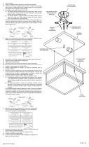
2) Find the appropriate threaded holes on mounting strap.
Assemble mounting screws into threaded holes.
3) Attach mounting strap to outlet box. (Screws not provided).
Mounting strap can be adjusted to suit position of fixture.
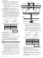
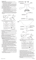
4) Grounding instructions: (See Illus. A or B).
A) On fixtures where mounting strap is provided with a hole
and two raise dimples. Wrap ground wire from outlet
box around green ground screw, and thread into hole.
B) On fixtures where a cupped washer is provided. Attach
ground wire from outlet box under cupped washer and
green ground screw, and thread into mounting strap.
If fixture is provided with ground wire. Connect fixture
ground wire to outlet box ground wire with wire connector.
(Not provided.) After following the above steps. Never connect
ground wire to black or white power supply wires.
5) Make wire connections (connectors not provided.) Reference
chart below for correct connections and wire accordingly.
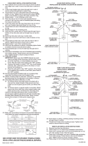
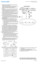
6) Push fixture to ceiling, carefully passing mounting screws
through holes in fixture.
7) Thread threaded balls onto mounting screw. Tighten
mounting screws to secure fixture to ceiling.
8) Insert recommended bulb.
9) Screw short end of threaded pipe with hexnut into coupling
at bottom of fixture.
10) Raise bottom glass up to fixture. Pass hole in bottom glass
over end of threaded pipe.
11) Slip rubber washer over end of threaded pipe. Thread
hexnut onto end of threaded pipe. Tighten hexnut to secure
bottom glass in place. (DO NOT over tighten.)
12) Pass hole in bottom trim over end of threaded pipe.
13) Thread finial onto end of threaded pipe. (DO NOT over
tighten.)
1) APAGAR LA ALIMENTACIÓN DE ENERGIE ELÈTRICA.
IMPORTANTE: Antes de comenzar, NUNCA trate de trabajar
sin antes desconectar la corriente hasta que el trabajo se
termine.
a) Vaya a la caja principal de fusibles, o interruptor o caja
de circuitos de su casa. Coloque el interruptor de la
corriente principal en posición de apagado “OFF”.
b) Desatornille el (los) fusible (s), o coloque el interruptor o
interruptores del breaker en posición de apagado “OFF”,
que controla (n) la corriente hacia el artefacto o habit
ación donde está trabajando.
c) Coloque el interruptor de pared en posición de apagado
“OFF”. Si el artefacto que se va a reemplazar tiene un
interruptor o cadena que se jala, colóquelos en la
posición de apagado “OFF”.
2) Encuentre los agujeros roscados apropiados en la abrazadera
de montaje. Monte los tornillos de montaje en los agujeros
roscados.
3) Acople la abrazadera de montaje a la caja de salida. (No se
provee tornillos). La abrazadera de montaje se puede ajustar
para acomodar la posición del artefacto.
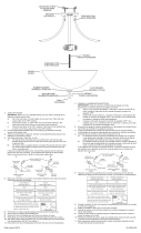
4) Instrucciones de conexión a tierra (Vea la ilustración A o B)
A) En artefactos donde se provee la abrazadera de
montaje con un agujero y dos depresiones onduladas:
Envuelva el alambre de tierra de la caja de salida
alrededor del tornillo de tierra verde y rosque en el
agujero.
B) En artefactos donde se provee una arandela cóncava.
Acople el alambre de tierra de la caja de salida debajo de
la arandela cóncava y del tornillo de tierra verde, y
rosque el tornillo en la abrazadera de montaje.
Si el artefacto está provisto con alambre de tierra: Conecte
el alambre de tierra del artefacto con el alambre de tierra de
la caja de salida con un conector de alambre. (No se provee.)
5) Haga las conexiones de alambres (No se provee conectores).
Vea la tabla de referencia de abajo para las conexiones
correctas y los alambres correspondientes.
6) Empuje el artefacto al cielo raso pasando cuidadosamente
los tornillos de montaje a través de los agujeros en el artefacto.
7) Atornille las bolas roscadas en los tornillos de montaje.
Ariete las bolas roscadas para sujetar el artefacto a la techo.
8) Inserte la bombilla recomendada.
9) Atornille el extremo del tubo roscado de cuenta en el
acoplamiento en la parte inferior del artefacto.
10) Pase el agujero en el vidrio sobre el extremo del tubo
roscada.
11) Resbale la arandela de caucho encima del tubo roscado.
Atornille el tuerca hexagonal en el tubo roscado. Apretar la
tuerca hexagonal para fijar el vidrio en su lugar. (NO apriete
excesivamente.)
12) Pase la guarnición inferior encima del tubo roscado
13) Atornille el capuchón al tubo roscado. (NO apriete
excesivamente.)
GREEN GROUND
SCREW
CUPPED
WASHER
A
B
OUTLET BOX
GROUND
FIXTURE
GROUND
DIMPLES
WIRE CONNECTOR
(NOT PROVIDED)
OUTLET BOX
GROUND
GREEN GROUND
SCREW
FIXTURE
GROUND
Connect Black or
Red Supply Wire to:
Connect
White Supply Wire to:
Black White
*Parallel cord (round & smooth) *Parallel cord (square & ridged)
Clear, Brown, Gold or Black
without tracer
Clear, Brown, Gold or Black
with tracer
Insulated wire (other than green)
with copper conductor
Insulated wire (other than green)
with silver conductor
*Note: When parallel wires (SPT I & SPT II)
are used. The neutral wire is square shaped
or ridged and the other wire will be round in
shape or smooth (see illus.)
Neutral Wire
ARANDELA
CONCAVA
A
B
TIERRA DE LA
CAJA DE SALIDA
TORNILLO DE TIERRA,
VERDE
DEPRESIONES
TIERRA
ARTEFACTO
CONECTOR DE ALAMBRE
(NO SE PROVEE)
TIERRA DE LA
CAJA DE SALIDA
TORNILLO DE TIERRA,
VERDE
TIERRA
ARTEFACTO
Conectar el alambre de
suministro negro o rojo al
Conectar el alambre de
suministro blanco al
Negro Blanco
*Cordon paralelo (redondo y liso)
*Cordon paralelo (cuadrado y estriado)
Claro, marrón, amarillio o negro
sin hebra identificadora
Claro, marrón, amarillio o negro
con hebra identificadora
Alambre aislado (diferente del verde)
con conductor de cobre
Alambre aislado (diferente del
verde) con conductor de plata
*Nota: Cuando se utiliza alambre paralelo
(SPT I y SPT II). El alambre neutro es de forma
cuadrada o estriada y el otro alambre será de
forma redonda o lisa. (Vea la ilustracíón).
Hilo Neutral
Date Issued: 8/23/13 IS-49518-US
MOUNTING STRAP
PLANCHA PARA MONTAR
FIXTURE
ARTEFACTO
THREADED BALL
BOLA ROSCADO
FINIAL
CAPUCHON
HEXNUT
TUERCA HEXAGONAL
RUBBER WASHER
ARANDELA DE CAUCHO
BOTTOM GLAS
VIDRIO
BOTTOM TRIM
GUARNICIÓN INFERIOR
HEXNUT
TUERCA HEXAGONAL
THREADED PIPE
TUBO ROSCADO
-
 1
1

Kichler Lighting 49518OZ Manual de usuario
- Tipo
- Manual de usuario
en otros idiomas
- English: Kichler Lighting 49518OZ User manual
Artículos relacionados
-
 Kichler Lighting 42565BK Manual de usuario
-
 Kichler Lighting 42563BPT Manual de usuario
-
 Kichler Lighting 3674OZ Manual de usuario
-
 Kichler Lighting 9811PR Manual de usuario
-
 Kichler Lighting 43232NI Manual de usuario
-
 Kichler Lighting 42386AP Manual de usuario
-
 Kichler Lighting 42900NI Manual de usuario
-
 Kichler Lighting 43191AUB Manual de usuario
-
 Kichler Lighting 42387AP Manual de usuario
-
 Kichler Lighting 8653NI Manual de usuario


