GYS MULTIWELD FV 220M-C El manual del propietario
- Categoría
- Sistema de soldadura
- Tipo
- El manual del propietario

C73520_V9_18/03/2021
FR
2-10 / 65-80
MULTIWELD
250T-C / 320T-C / FV 220M-C
www.gys.fr
Poste à souder MIG/MAG et MMA
MIG/MAG and MMA welding machine
MIG/MAG und E-Hand-Schweißgerät
Equipo de soldadura MIG/MAG y MMA
Сварочный аппарат МИГ/МАГ и ММА
MIG/MAG en MMA Lasapparaat
Dispositivo di saldatura MIG/MAG e MMA
EN
11-19 / 65-80
DE
20-28 / 65-80
ES
29-37 / 65-80
RU
38-46 / 65-80
NL
47-55 / 65-80
IT
56-64 / 65-80

2
MULTIWELD 250T-C / 320T-C / FV 220M-C
FR
AVERTISSEMENTS - RÈGLES DE SÉCURITÉ
CONSIGNE GÉNÉRALE
Ces instructions doivent être lues et bien comprises avant toute opération. Toute modi-
cation ou maintenance non indiquée dans le manuel ne doit pas être entreprise.
Tout dommage corporel ou matériel dû à une utilisation non-conforme aux instructions de ce manuel ne pourra être retenu à la
charge du fabricant. En cas de problème ou d’incertitude, consulter une personne qualiée pour manier correctement l’installation.
ENVIRONNEMENT
Ce matériel doit être utilisé uniquement pour faire des opérations de soudage dans les limites indiquées par la plaque signalétique
et/ou le manuel. Il faut respecter les directives relatives à la sécurité. En cas d’utilisation inadéquate ou dangereuse, le fabricant ne
pourra être tenu responsable.
L’installation doit être utilisée dans un local sans poussière, ni acide, ni gaz inammable ou autres substances corrosives de même
pour son stockage. S’assurer d’une circulation d’air lors de l’utilisation.
Plages de température :
Utilisation entre -10 et +40°C (+14 et +104°F).
Stockage entre -20 et +55°C (-4 et 131°F).
Humidité de l’air :
Inférieur ou égal à 50% à 40°C (104°F).
Inférieur ou égal à 90% à 20°C (68°F).
Altitude :
Jusqu’à 1000 m au-dessus du niveau de la mer (3280 pieds).
PROTECTION INDIVIDUELLE ET DES AUTRES
Le soudage à l’arc peut être dangereux et causer des blessures graves voire mortelles.
Le soudage expose les individus à une source dangereuse de chaleur, de rayonnement lumineux de l’arc, de champs électromagné-
tiques (attention au porteur de pacemaker), de risque d’électrocution, de bruit et d’émanations gazeuses.
Pour bien se protéger et protéger les autres, respecter les instructions de sécurité suivantes :
An de se protéger de brûlures et rayonnements, porter des vêtements sans revers, isolants, secs, ignifugés et en
bon état, qui couvrent l’ensemble du corps.
Utiliser des gants qui garantissent l’isolation électrique et thermique.
Utiliser une protection de soudage et/ou une cagoule de soudage d’un niveau de protection susant (variable selon
les applications). Protéger les yeux lors des opérations de nettoyage. Les lentilles de contact sont particulièrement
proscrites.
Il est parfois nécessaire de délimiter les zones par des rideaux ignifugés pour protéger la zone de soudage des rayons
de l’arc, des projections et des déchets incandescents.
Informer les personnes dans la zone de soudage de ne pas xer les rayons de l’arc ni les pièces en fusion et de porter
les vêtements adéquats pour se protéger.
Utiliser un casque contre le bruit si le procédé de soudage atteint un niveau de bruit supérieur à la limite autorisée
(de même pour toute personne étant dans la zone de soudage).
Tenir à distance des parties mobiles (ventilateur) les mains, cheveux, vêtements.
Ne jamais enlever les protections carter du groupe froid lorsque la source de courant de soudage est sous tension,
le fabricant ne pourrait être tenu pour responsable en cas d’accident.
Les pièces qui viennent d’être soudées sont chaudes et peuvent provoquer des brûlures lors de leur manipulation.
Lors d’intervention d’entretien sur la torche ou le porte-électrode, il faut s’assurer que celui-ci soit susamment froid
en attendant au moins 10 minutes avant toute intervention. Le groupe froid doit être allumé lors de l’utilisation d’une
torche refroidie eau an d’être sûr que le liquide ne puisse pas causer de brûlures.
Il est important de sécuriser la zone de travail avant de la quitter an de protéger les personnes et les biens.
FUMÉES DE SOUDAGE ET GAZ
Les fumées, gaz et poussières émis par le soudage sont dangereux pour la santé. Il faut prévoir une ventilation
susante, un apport d’air est parfois nécessaire. Un masque à air frais peut être une solution en cas d’aération
insusante.
Vérier que l’aspiration est ecace en la contrôlant par rapport aux normes de sécurité.

3
MULTIWELD 250T-C / 320T-C / FV 220M-C
FR
Attention le soudage dans des milieux de petites dimensions nécessite une surveillance à distance de sécurité. Par ailleurs le soudage
de certains matériaux contenant du plomb, cadmium, zinc ou mercure voire du béryllium peuvent être particulièrement nocifs,
dégraisser également les pièces avant de les souder.
Les bouteilles doivent être entreposées dans des locaux ouverts ou bien aérés. Elles doivent être en position verticale et maintenues
à un support ou sur un chariot.
Le soudage doit être proscrit à proximité de graisse ou de peinture.
RISQUE DE FEU ET D’EXPLOSION
Protéger entièrement la zone de soudage, les matières inammables doivent être éloignées d’au moins 11 mètres.
Un équipement anti-feu doit être présent à proximité des opérations de soudage.
Attention aux projections de matières chaudes ou d’étincelles et même à travers des ssures, elles peuvent être source d’incendie
ou d’explosion.
Éloigner les personnes, les objets inammables et les containers sous pressions à une distance de sécurité susante.
Le soudage dans des containers ou des tubes fermés est à proscrire et dans le cas où ils sont ouverts il faut les vider de toute matière
inammable ou explosive (huile, carburant, résidus de gaz …).
Les opérations de meulage ne doivent pas être dirigées vers la source de courant de soudage ou vers des matières inammables.
BOUTEILLES DE GAZ
Le gaz sortant des bouteilles peut être source de suocation en cas de concentration dans l’espace de soudage (bien
ventiler).
Le transport doit être fait en toute sécurité : bouteilles fermées et la source de courant de soudage éteinte. Elles doivent
être entreposées verticalement et maintenues par un support pour limiter le risque de chute.
Fermer la bouteille entre deux utilisations. Attention aux variations de température et aux expositions au soleil.
La bouteille ne doit pas être en contact avec une amme, un arc électrique, une torche, une pince de masse ou toutes
autres sources de chaleur ou d’incandescence.
Veiller à la tenir éloignée des circuits électriques et de soudage et donc ne jamais souder une bouteille sous pression.
Attention lors de l’ouverture du robinet de la bouteille, il faut éloigner la tête la robinetterie et s’assurer que le gaz utilisé
est approprié au procédé de soudage.
SÉCURITÉ ÉLECTRIQUE
Le réseau électrique utilisé doit impérativement avoir une mise à la terre. Utiliser la taille de fusible recommandée
sur le tableau signalétique. Une décharge électrique peut être une source d’accident grave direct ou indirect, voire
mortel.
Ne jamais toucher les parties sous tension à l’intérieur comme à l’extérieur de la source de courant sous-tension (Torches, pinces,
câbles, électrodes) car celles-ci sont branchées au circuit de soudage.
Avant d’ouvrir la source de courant de soudage, il faut la déconnecter du réseau et attendre 2 minutes. an que l’ensemble des
condensateurs soit déchargé.
Ne pas toucher en même temps la torche ou le porte-électrode et la pince de masse.
Veiller à changer les câbles, torches si ces derniers sont endommagés, par des personnes qualiées et habilitées. Dimensionner la
section des câbles en fonction de l’application. Toujours utiliser des vêtements secs et en bon état pour s’isoler du circuit de soudage.
Porter des chaussures isolantes, quel que soit le milieu de travail.
CLASSIFICATION CEM DU MATERIEL
Ce matériel de Classe A n’est pas prévu pour être utilisé dans un site résidentiel où le courant électrique est
fourni par le réseau public d’alimentation basse tension. Il peut y avoir des dicultés potentielles pour assurer la
compatibilité électromagnétique dans ces sites, à cause des perturbations conduites, aussi bien que rayonnées à
fréquence radioélectrique.
MULTIWELD 250T-C / 320T-C / FV 220M-C :
Ce matériel est conforme à la CEI 61000-3-11.
MULTIWELD 250T-C / 320T-C / FV 220M-C :
Ce matériel n’est pas conforme à la CEI 61000-3-12 et est destiné à être raccordé à des réseaux basse tension
privés connectés au réseau public d’alimentation seulement au niveau moyenne et haute tension. S’il est connecté
à un réseau public d’alimentation basse tension, il est de la responsabilité de l’installateur ou de l’utilisateur du
matériel de s’assurer, en consultant l’opérateur du réseau de distribution, que le matériel peut être connecté.

4
MULTIWELD 250T-C / 320T-C / FV 220M-C
FR
EMISSIONS ELECTRO-MAGNETIQUES
Le courant électrique passant à travers n’importe quel conducteur produit des champs électriques et magnétiques
(EMF) localisés. Le courant de soudage produit un champ électromagnétique autour du circuit de soudage et du
matériel de soudage.
Les champs électromagnétiques EMF peuvent perturber certains implants médicaux, par exemple les stimulateurs cardiaques. Des
mesures de protection doivent être prises pour les personnes portant des implants médicaux. Par exemple, restrictions d’accès pour
les passants ou une évaluation de risque individuelle pour les soudeurs.
Tous les soudeurs devraient utiliser les procédures suivantes an de minimiser l’exposition aux champs électromagnétiques provenant
du circuit de soudage:
• positionner les câbles de soudage ensemble – les xer les avec une attache, si possible;
• se positionner (torse et tête) aussi loin que possible du circuit de soudage;
• ne jamais enrouler les câbles de soudage autour du corps;
• ne pas positionner le corps entre les câbles de soudage. Tenir les deux câbles de soudage sur le même côté du corps;
• raccorder le câble de retour à la pièce mise en œuvre aussi proche que possible à la zone à souder;
• ne pas travailler à côté de la source de courant de soudage, ne pas s’assoir dessus ou ne pas s’y adosser ;
• ne pas souder lors du transport de la source de courant de soudage ou le dévidoir.
Les porteurs de stimulateurs cardiaques doivent consulter un médecin avant d’utiliser ce matériel.
L’exposition aux champs électromagnétiques lors du soudage peut avoir d’autres eets sur la santé que l’on ne
connaît pas encore.
RECOMMANDATIONS POUR EVALUER LA ZONE ET L’INSTALLATION DE SOUDAGE
Généralités
L’utilisateur est responsable de l’installation et de l’utilisation du matériel de soudage à l’arc suivant les instructions du fabricant. Si
des perturbations électromagnétiques sont détectées, il doit être de la responsabilité de l’utilisateur du matériel de soudage à l’arc
de résoudre la situation avec l’assistance technique du fabricant. Dans certains cas, cette action corrective peut être aussi simple
qu’une mise à la terre du circuit de soudage. Dans d’autres cas, il peut être nécessaire de construire un écran électromagnétique
autour de la source de courant de soudage et de la pièce entière avec montage de ltres d’entrée. Dans tous les cas, les perturbations
électromagnétiques doivent être réduites jusqu’à ce qu’elles ne soient plus gênantes.
Evaluation de la zone de soudage
Avant d’installer un matériel de soudage à l’arc, l’utilisateur doit évaluer les problèmes électromagnétiques potentiels dans la zone
environnante. Ce qui suit doit être pris en compte:
a) la présence au-dessus, au-dessous et à côté du matériel de soudage à l’arc d’autres câbles d’alimentation, de commande, de
signalisation et de téléphone;
b) des récepteurs et transmetteurs de radio et télévision;
c) des ordinateurs et autres matériels de commande;
d) du matériel critique de sécurité, par exemple, protection de matériel industriel;
e) la santé des personnes voisines, par exemple, emploi de stimulateurs cardiaques ou d’appareils contre la surdité;
f) du matériel utilisé pour l’étalonnage ou la mesure;
g) l’immunité des autres matériels présents dans l’environnement.
L’utilisateur doit s’assurer que les autres matériels utilisés dans l’environnement sont compatibles. Cela peut exiger des mesures de
protection supplémentaires;
h) l’heure du jour où le soudage ou d’autres activités sont à exécuter.
La dimension de la zone environnante à prendre en compte dépend de la structure du bâtiment et des autres activités qui s’y
déroulent. La zone environnante peut s’étendre au-delà des limites des installations.
Evaluation de l’installation de soudage
Outre l’évaluation de la zone, l’évaluation des installations de soudage à l’arc peut servir à déterminer et résoudre les cas de
perturbations. Il convient que l’évaluation des émissions comprenne des mesures in situ comme cela est spécié à l’Article 10 de la
CISPR 11. Les mesures in situ peuvent également permettre de conrmer l’ecacité des mesures d’atténuation.
RECOMMANDATIONS SUR LES METHODES DE REDUCTION DES EMISSIONS ELECTROMAGNETIQUES
a. Réseau public d’alimentation: Il convient de raccorder le matériel de soudage à l’arc au réseau public d’alimentation selon
les recommandations du fabricant. Si des interférences se produisent, il peut être nécessaire de prendre des mesures de prévention
supplémentaires telles que le ltrage du réseau public d’alimentation. Il convient d’envisager de blinder le câble d’alimentation dans
un conduit métallique ou équivalent d’un matériel de soudage à l’arc installé à demeure. Il convient d’assurer la continuité électrique
du blindage sur toute sa longueur. Il convient de raccorder le blindage à la source de courant de soudage pour assurer un bon contact
électrique entre le conduit et l’enveloppe de la source de courant de soudage.

5
MULTIWELD 250T-C / 320T-C / FV 220M-C
FR
b. Maintenance du matériel de soudage à l’arc : Il convient que le matériel de soudage à l’arc soit soumis à l’entretien de routine
suivant les recommandations du fabricant. Il convient que tous les accès, portes de service et capots soient fermés et correctement
verrouillés lorsque le matériel de soudage à l’arc est en service. Il convient que le matériel de soudage à l’arc ne soit modié en aucune
façon, hormis les modications et réglages mentionnés dans les instructions du fabricant. Il convient, en particulier, que l’éclateur d’arc
des dispositifs d’amorçage et de stabilisation d’arc soit réglé et entretenu suivant les recommandations du fabricant.
c. Câbles de soudage : Il convient que les câbles soient aussi courts que possible, placés l’un près de l’autre à proximité du sol ou
sur le sol.
d. Liaison équipotentielle : Il convient d’envisager la liaison de tous les objets métalliques de la zone environnante. Toutefois, des
objets métalliques reliés à la pièce à souder accroissent le risque pour l’opérateur de chocs électriques s’il touche à la fois ces éléments
métalliques et l’électrode. Il convient d’isoler l’opérateur de tels objets métalliques.
e. Mise à la terre de la pièce à souder : Lorsque la pièce à souder n’est pas reliée à la terre pour la sécurité électrique ou en raison
de ses dimensions et de son emplacement, ce qui est le cas, par exemple, des coques de navire ou des charpentes métalliques de
bâtiments, une connexion raccordant la pièce à la terre peut, dans certains cas et non systématiquement, réduire les émissions. Il
convient de veiller à éviter la mise à la terre des pièces qui pourrait accroître les risques de blessure pour les utilisateurs ou endommager
d’autres matériels électriques. Si nécessaire, il convient que le raccordement de la pièce à souder à la terre soit fait directement, mais
dans certains pays n’autorisant pas cette connexion directe, il convient que la connexion soit faite avec un condensateur approprié
choisi en fonction des réglementations nationales.
f. Protection et blindage : La protection et le blindage sélectifs d’autres câbles et matériels dans la zone environnante peuvent
limiter les problèmes de perturbation. La protection de toute la zone de soudage peut être envisagée pour des applications spéciales.
TRANSPORT ET TRANSIT DE LA SOURCE DE COURANT DE SOUDAGE
30°
La source de courant de soudage est équipée de deux poignées supérieures permettant le portage
à la main à deux personnes. Attention à ne pas sous-évaluer son poids.
Ne pas utiliser les câbles ou torche pour déplacer la source de courant de soudage. Elle doit être déplacée en position
verticale.
Ne pas faire transiter la source de courant au-dessus de personnes ou d’objets.
Ne jamais soulever une bouteille de gaz et la source de courant en même temps. Leurs normes de transport sont
distinctes.
Il est préférable d’enlever la bobine de l avant tout levage ou transport de la source de courant de soudage.
INSTALLATION DU MATERIEL
• Mettre la source de courant de soudage sur un sol dont l’inclinaison maximum est de 10°.
• Prévoir une zone susante pour aérer la source de courant de soudage et accéder aux commandes.
• Ne pas utiliser dans un environnement comportant des poussières métalliques conductrices.
• La source de courant de soudage doit être à l’abri de la pluie battante et ne pas être exposée aux rayons du soleil.
• Le matériel MULTIWELD 250T-C est de degré de protection IP21, signiant :
- une protection contre l’accès aux parties dangereuses des corps solides de diam >12.5 mm et,
- une protection contre les chutes verticales de gouttes d’eau
• Le matériel MULTIWELD 320T-C/220M-C est de degré de protection IP23, signiant :
- une protection contre l’accès aux parties dangereuses des corps solides de diam >12.5 mm et,
- une protection contre la pluie dirigée à 60° par rapport à la verticale.
Ce matériel peut donc être utilisé à l’extérieur en accord avec l’indice de protection IP23.
Les câbles d’alimentation, de rallonge et de soudage doivent être totalement déroulés an d’éviter toute surchaue.
Le fabricant n’assume aucune responsabilité concernant les dommages provoqués à des personnes et objets dus à
une utilisation incorrecte et dangereuse de ce matériel.
Les courants de soudage vagabonds peuvent détruire les conducteurs de terre, endommager l’équipement et les
dispositifs électriques et causer des échauements de composants pouvant entrainer un incendie.
- Toutes les connexions de soudages doivent être connectées fermement, les vérier régulièrement !
- S’assurer que la xation de la pièce est solide et sans problèmes électriques !
- Attacher ou suspendre tous les éléments conducteurs d’électricité de la source de soudage comme le châssis, le chariot et les
systèmes de levage pour qu’ils soient isolés !
- Ne pas déposer d’autres équipements comme des perceuses, dispositifs d’autage, etc sur la source de soudage, le chariot, ou les
systèmes de levage sans qu’ils soient isolés !
- Toujours déposer les torches de soudage ou portes électrodes sur une surface isolée quand ils ne sont pas utilisés !

6
MULTIWELD 250T-C / 320T-C / FV 220M-C
FR
ENTRETIEN / CONSEILS
• L’entretien ne doit être eectué que par une personne qualiée. Un entretien annuel est conseillé.
• Couper l’alimentation en débranchant la prise, et attendre deux minutes avant de travailler sur le matériel. A
l’intérieur, les tensions et intensités sont élevées et dangereuses.
• Régulièrement, enlever le capot et dépoussiérer à la souette. En proter pour faire vérier la tenue des
connexions électriques avec un outil isolé par un personnel qualié.
• Contrôler régulièrement l’état du cordon d’alimentation. Si le câble d’alimentation est endommagé, il doit
être remplacé par le fabricant, son service après-vente ou une personne de qualication similaire, an d’éviter
tout danger.
• Laisser les ouïes de la source de courant de soudage libres pour l’entrée et la sortie d’air.
• Ne pas utiliser cette source de courant/tension de soudage pour dégeler des canalisations, recharger des
batteries/accumulateurs ou démarrer des moteurs.
INSTALLATION – FONCTIONNEMENT PRODUIT
Seul le personnel expérimenté et habilité par le fabricant peut eectuer l’installation. Pendant l’installation, s’assurer que le générateur
est déconnecté du réseau.
Il est recommandé d’utiliser les câbles de soudage fournis avec l’appareil an d’obtenir les réglages optimum du produit.
DESCRIPTION
Merci de votre choix ! An de tirer le maximum de satisfaction de votre poste, veuillez lire avec attention ce qui suit :
Les postes de la gamme MULTIWELD sont des postes semi-automatiques MIG/MAG, l fourré et MMA. Ils sont à réglage manuel et
assistés de la grille d’ajustement présente sur le produit. Ils sont recommandés pour le soudage des aciers, inox et aluminium.
ALIMENTATION ELECTRIQUE
• Le MULTIWELD 250T-C/320T-C est livré avec une prise 16 A de type EN 60309-1 et doit être branché à une installation électrique
triphasée 400 V (50-60 Hz) à quatre ls avec le neutre relié à la terre.
• Le MULTIWELD FV 220M-C est livré avec une prise 16 A de type CEE7/7 et ne doit être utilisé que sur une installation électrique
monophasée 230 V (50 - 60 Hz) à trois ls avec un neutre relié à la terre.
Ce produit, doté d’un système « Flexible Voltage », peut s’alimenter sur une installation électrique avec terre, comprise entre 110V
et 230V (50 – 60Hz).
Le courant eectif absorbé (I1e) est indiqué sur le matériel, pour les conditions d’utilisation maximales. Vérier que l’alimentation
et ses protections (fusible et/ou disjoncteur) sont compatibles avec le courant nécessaire en utilisation. Dans certains pays, il peut
être nécessaire de changer la prise pour permettre une utilisation aux conditions maximales.
• Le MULTIWELD FV 220M-C est équipé de la fonction Protect 400 (P400) : l’appareil se met en protection (voyant de protection
clignote) si la tension d’alimentation est supérieure à 265 V. Le fonctionnement normal reprend dès que la tension d’alimentation
revient dans sa plage nominale.
UTILISATION DE RALLONGE ÉLECTRIQUE
Toutes les rallonges doivent avoir une taille et une section appropriées à la tension de l’appareil.
Utiliser une rallonge conforme aux réglementations nationales.
Tension d’entrée Section de la rallonge (<45m)
MULTIWELD 250T-C/320T-C
400 V - 3~ 2.5 mm²
MULTIWELD FV 220M-C
230 V - 1~
2.5 mm²
110 V - 1~
DESCRIPTION DU POSTE (FIG. I)
1- Support de bobine 7- Connecteur de pince de masse
2- Poignées 8- Anneaux d’élingage
3- Achage digital 9- Raccord gaz
4- Réglage des paramètres de soudage 10- Interrupteur on/o
5- Raccord de torche standard européen 11- Câble d'alimentation
6- Câble d’inversion de polarité 12- Grille externe
13- Prise 36V DC pour dispositif de préchauage de gaz

7
MULTIWELD 250T-C / 320T-C / FV 220M-C
FR
INTERFACE HOMME MACHINE (IHM) (FIG. V)
1-
Indicateur de surchaue/surtension (250T-C/320T-C)
Indicateur de surchaue/surtension/P400 (FV 220M-C)
7- Indicateur de fonction MIG
2- Achage de la tension 8- Bouton de sélection de fonction 2T/4T
3- Achage du courant et de la vitesse de l 9- Bouton de sélection MIG/MMA
4- Indicateur de courant 10- Réglage dynamique de l'arc de soudage
5- Indicateur de vitesse de l 11- Réglage de la vitesse du l (MIG) / réglage du courant (MMA)
6- Indicateur de fonction MMA 12- Réglage de la tension
MISE EN MARCHE
L’interrupteur marche/arrêt se trouve à l’arrière du produit, tourner sur «I» pour allumer le générateur. Cet interrupteur ne doit
jamais être tourné sur «O» pendant le soudage.
SOUDAGE SEMI-AUTOMATIQUE EN ACIER/INOX (MODE MAG)
Sélectionner la tension de sortie et régler la vitesse l selon les recommandations apparaissant dans la table gurant sur l’appareil
en fonction de l’épaisseur des pièces à souder (g. VI).
Le MULTIWELD 250T-C/320T-C peut souder du l acier de Ø 0.6/1.2 mm, et inox de Ø 0.8/1.2 mm.
Le MULTIWELD FV 220M-C peut souder du l acier de Ø 0.6/1.0 mm, et inox de Ø 0.8/1.0 mm.
L’appareil est livré d’origine pour fonctionner avec du l Ø 0,8 mm en acier (galet Ø 0.8/1.0). Le tube contact, la gorge du galet,
la gaine de la torche sont prévus pour cette application. Pour pouvoir souder du l de diamètre 0.6, utiliser une torche dont la lon-
gueur n’excède pas 3 m. Il convient de changer le tube contact (g. II-A) ainsi que le galet du motodévidoir par un modèle ayant
une gorge de 0,6 (ref. 042339). Dans ce cas, le positionner de telle façon à observer l’inscription 0.6.
L’utilisation en acier nécessite un gaz spécique au soudage (Ar+CO2). La proportion de CO2 peut varier selon le type de gaz uti-
lisé. Pour l’inox, utiliser un mélange à 2% de CO2 . En cas de soudage avec du CO2 pur, il est nécessaire de connecter un dispositif
de préchauage de gaz sur la bouteille de gaz (référence Gys 046511 pour une version 230V). Il est également possible d’utiliser
un module standard de préchauage (36V) qui peut être connecté à la prise d’alimentation 36V située à proximité de la bobine de
l de soudure, derrière la porte latérale (g. I-13). Veuillez noter que cette alimentation 36V DC est également compatible avec des
préchaueurs 36V AC. Pour des besoins spéciques en gaz, veuillez contacter votre distributeur de gaz. Le débit de gaz pour l’acier
est compris entre 8 et 12 litres / minute selon l’environnement.
SOUDAGE SEMI-AUTOMATIQUE ALUMINIUM (MODE MIG)
Sélectionner la tension de sortie et régler la vitesse l selon les recommandations apparaissant dans la table gurant sur l’appareil
en fonction de l’épaisseur des pièces à souder (g. VI).
Le MULTIWELD 250T-C/320T-C/FV 220M-C peut être équipé pour souder avec du l alu de Ø 0.8 et 1.0 mm (g. II-B).
L’utilisation en aluminium nécessite un gaz spécique argon pur (Ar). Pour le choix du gaz, demander conseil à un distributeur de
gaz. Le débit de gaz en aluminium se situe entre 15 et 25 l/min selon l’environnement et l’expérience du soudeur.
Voici les diérences entre les utilisations acier et aluminium :
- Utiliser des galets spéciques pour le soudage alu.
- Mettre un minimum de pression des galets presseurs du motodévidoir pour ne pas écraser le l.
- Utiliser le tube capillaire uniquement pour le soudage acier/inox.
- La préparation d’une torche alu demande une attention particulière. Elle possède une gaine téon an de réduire les frottements.
Ne pas couper la gaine au bord du raccord, elle doit dépasser de la longueur du tube capillaire qu’elle remplace et sert à guider le
l à partir des galets.
- Tube contact : utiliser un tube contact SPECIAL aluminium correspondant au diamètre du l.
SOUDAGE FIL « NO GAS »
Sélectionner la tension de sortie et régler la vitesse l selon les recommandations apparaissant dans la table gurant sur l’appareil
en fonction de l’épaisseur des pièces à souder (g VI).
Le MULTIWELD 250T-C/320T-C peut souder du l « No Gas » de Ø 0.9 à 1.2 mm à condition d’inverser la polarité (g. III - couple
de serrage maximum de 5 Nm). Pour paramétrer cette utilisation, se référer aux indications de la page 68. Souder du l fourré avec
une buse standard peut entraîner une surchaue et la détérioration de la torche. Enlever la buse d’origine (g. III).
SOUDAGE SEMI-AUTOMATIQUE MIG / MAG
BRANCHEMENT ET CONSEILS
• Branchez la pince de masse sur le connecteur de raccordement positif (+) ou négatif (-) en fonction du type de l utilisé (en règle
générale sur le -).
SÉLECTION DU MODE ET RÉGLAGE
Appuyer sur le bouton gauche pour sélectionner le mode de soudage MIG/MAG et appuyer sur le bouton droit pour choisir
le comportement de la gâchette : 2T ou 4T
(le comportement de la gâchette est disponible seulement pour le mode MIG)
.

8
MULTIWELD 250T-C / 320T-C / FV 220M-C
FR
1. Régler la tension de soudage :
Ajuster la tension de soudage à l’aide de la molette de gauche en fonction
du travail à eectuer. La consigne de tension est indiquée sur l’acheur
de gauche.
2. Régler la vitesse de l :
Ajuster la vitesse de l à l’aide de la molette centrale en fonction
du travail à eectuer. La consigne de vitesse est indiquée sur l’acheur
de droite.
3. Régler l’inductance :
Ajuster le niveau d’inductance à l’aide de la molette de droite , valeur
relative allant de MIN à MAX. Plus le niveau d’inductance est faible et plus l’arc
sera dur et directif, plus le niveau d’inductance est élevé et plus l’arc sera doux
avec peu de projections.
I
N
V
E
R
T
E
R
T
E
C
H
N
O
L
O
G
Y
MIG
m/min
V
V
2T 4TMMA MIG
Ø 2.5
Ø 2
Ø 4
Ø 5
+
–
+
–
MIG
MIG
Ø 3.2
M
A
X
M
I
N
2
3
4
5
6
7
MMA
M
I
N
M
A
X
inductance
A
Les zones de couleur noir ne sont pas utiles dans ce mode.
Sélectionner la tension de sortie et régler la vitesse l selon les recommandations apparaissant dans la table gurant sur l’appareil
en fonction de l’épaisseur des pièces à souder (g. VI).
INSTALLATION DE LA BOBINE ET CHARGEMENT DU FIL (FIG. IV)
Le MULTIWELD 250T-C/320T-C/FV 220M-C accueille des bobines Ø 200/300 mm (écologique).
• Ôter de la torche le tube contact (g. D) ainsi que la buse (g. E).
Fig A :
• Ouvrir la trappe du poste.
• Positionner la bobine sur son support (3).
• Régler le frein (4) pour éviter lors de l’arrêt de la soudure que l’inertie de la bobine n’emmêle le l. De manière générale, ne pas
trop serrer, ce qui provoquerait une surchaue du moteur.
Fig B :
• Les galets fournis sont des galets double gorge (0.8 et 1.0). Pour un l acier de 0,8 mm, utiliser la gorge en V.
• Pour du l fourré, retourner le galet pour utiliser la gorge en 0,9 mm.
• Pour le l aluminium de 0,8 mm, remplacer le galet par un modèle avec une gorge de 8 mm en U (non fourni).
Fig C :
Pour régler la pression du moto-dévidoir, procéder comme suit :
• Desserrer la molette (3) au maximum et l’abaisser, insérer le l, puis refermer le moto-dévidoir sans serrer.
• Actionner le moteur en appuyant sur la gâchette de la torche.
• Serrer la molette tout en restant appuyé sur la gâchette de la torche. Lorsque le l commence à être entrainé, arrêter le serrage.
Attention : pour le l aluminium mettre un minimum de pression an de ne pas écraser le l.
• Faire sortir le l de la torche d’environ 5 cm, puis mettre au bout de la torche le tube contact adapté au l utilisé (g. D), ainsi
que la buse (g. E).
RACCORDEMENT GAZ
- Monter un manodétendeur adapté sur la bouteille de gaz. Le raccorder au poste à souder avec le tuyau fourni. Mettre les 2 col-
liers de serrage an d’éviter les fuites.
- Régler le débit de gaz en ajustant la molette de réglage située sur le manodétendeur.
NB : pour faciliter le réglage du débit de gaz, actionner les galets moteurs en appuyant sur la gâchette de la torche (desserrer la
molette du motodévidoir pour ne pas entraîner de l). Pression maximale de gaz : 0.5 MPa (5 bars). Cette procédure ne s’applique
pas au soudage en mode « No Gas ».
RISQUE DE BLESSURE LIÉ AUX COMPOSANTS MOBILES!
Les dévidoirs sont pourvus de composants mobiles qui peuvent happer les mains, les cheveux, les vêtements ou
les outils et entraîner par conséquent des blessures !
• Ne pas porter la main aux composants pivotants ou mobiles ou encore aux pièces d’entraînement!
• Veiller à ce que les couvercles du carter ou couvercles de protection restent bien fermés pendant le fonctionne-
ment !
• Ne pas porter de gants lors de l’enlement du l d’apport et du changement de la bobine du l d’apport.

9
MULTIWELD 250T-C / 320T-C / FV 220M-C
FR
SOUDAGE A L’ÉLECTRODE ENROBÉE
BRANCHEMENT ET CONSEILS
• Brancher les câbles, porte-électrode et pince de masse dans les connecteurs de raccordement,
• Respecter les polarités et intensités de soudage indiquées sur les boîtes d’électrodes,
• Enlever l’électrode du porte-électrode lorsque le poste n’est pas utilisé.
SÉLECTION DU MODE ET RÉGLAGES
Appuyer sur le bouton gauche pour sélectionner le mode MMA.
Réglage de l’intensité de soudage :
Ajuster le courant de soudage à l’aide de la molette centrale en fonction
du diamètre d’électrode et du type d’assemblage à réaliser. La consigne de
courant est indiquée sur l’acheur de droite.
I
N
V
E
R
T
E
R
T
E
C
H
N
O
L
O
G
Y
MIG
m/min
V
V
2T 4TMMA MIG
Ø 2.5
Ø 2
Ø 4
Ø 5
+
–
+
–
MIG
MIG
Ø 3.2
M
A
X
M
I
N
2
3
4
5
6
7
MMA
M
I
N
M
A
X
inductance
A
Les zones de couleur noir ne sont pas utiles dans ce mode.
RÉGLAGE DU COURANT DE SOUDAGE
Les réglages qui suivent correspondent à la plage de courant utilisable en fonction du type et du diamètre d’électrode. Ces plages
sont assez larges car elles dépendent de l’application et de la position de soudure.
250T-C / 320T-C
Ø d’électrode
(mm)
Rutile E6013
(A)
Basique E7018
(A)
1.6 30-60 30-55
2.0 50-70 50-80
2.5 60-100 80-110
3.2 80-150 90-140
4.0 100-200 125-210
5 150-290 200-260
6.3 200-385 220-340
FV 220M-C
Ø d’électrode
(mm)
Rutile E6013
(A)
Basique E7018
(A)
1.6 30-60 30-55
2.0 50-70 50-80
2.5 60-100 80-110
3.2 80-150 90-140
4.0 100-200 125-210
5 150-220 200-220
SOUDAGE A L’ÉLECTRODE ENROBÉE
• Le câble d’inversion de polarité doit être déconnectée en MMA pour brancher les câbles porte électrode et pince de masse dans
les connecteurs. Respecter les polarités indiquées sur l’emballage des électrodes.
• Respecter les règles classiques du soudage.
• Votre appareil est muni d’une fonctionnalité spécique aux Inverters :
L’Anti-Sticking vous permet de décoller facilement votre électrode sans la faire rougir en cas de collage. La fonction anti-sticking,
après son déclenchement, nécessite un temps d’attente d’environ 3 secondes avant de pouvoir reprendre une soudure normale.
PROTECTIONS ET CONSEILS
1 - Surchaue :
Ce poste est équipé d’une ventilation régulée par la température de l’appareil. Lorsque le poste passe en protection thermique, il
ne délivre plus de courant. La LED orange (g. VI-1) s’allume tant que la température du poste n’est pas redevenue normale.
• Laisser les ouïes de l’appareil libres pour l’entrée et la sortie d’air.
• Laisser l’appareil branché après soudage et pendant la protection thermique pour permettre le refroidissement.
2 - Surintensité :
Ce poste est équipé d’une mesure de courant au primaire. En cas de surintensité, la LED orange (g. VI-1) s’allumera. Dans ce cas
il faut éteindre et redémarrer l’appareil.
3 - P400 (FV 220M-C uniquement) :
Ce poste est équipée d’une protection contre les surtension au primaire. Dans ce cas, La LED orange (g. VI-1) clignotera 1 fois par
seconde.
4 - Observations :
• Respecter les règles classiques du soudage.
• S’assurer que la ventilation soit susante.
• Ne pas travailler sur une surface humide. An d’éviter les fuites de gaz, utiliser les colliers fournis dans la boîte d’accessoires.

10
MULTIWELD 250T-C / 320T-C / FV 220M-C
FR
- Veiller à ce que la bouteille de gaz soit maintenue en place avec le collier de xation, voir g. V.
- Régler le débit de gaz en ajustant la molette de réglage située sur le manodétendeur.
ANOMALIES, CAUSES, REMÈDES
SYMPTOMES CAUSES POSSIBLES REMEDES
Le voyant de protection s’allume
Dépassement du facteur de marche
Température ambiante supérieure à 40°C
Entrées d’air obstruées
Attendre l’extinction du témoin pour
reprendre le soudage.
Respecter le facteur de marche et assurer
une bonne ventilation.
Le voyant de protection clignote
(MULTIWELD FV 220M-C seulement)
Tension secteur hors tolérance maximale
Faites contrôler votre installation élec-
trique par une personne habilitée.
Le débit du l de soudage n’est pas
constant.
Des grattons obstruent l’orice.
Nettoyer le tube contact ou le changer et
remettre du produit anti-adhésion.
Ref. 041806.
Le l patine dans les galets.
• Contrôler la pression des galets ou les
remplacer.
• Diamètre du l non conforme au galet.
• Gaine guide l dans la torche non
conforme
Le moteur de dévidage ne fonctionne
pas.
Frein de la bobine ou galet trop serré. Desserrer le frein et les galets.
Problème d’alimentation.
Vérier que le bouton de mise en service
est sur la position marche.
Mauvais dévidage du l.
Gaine guide l sale ou endommagée. Nettoyer ou remplacer.
Galet presseur pas assez serré. Serrer le galet davantage.
Frein de la bobine trop serré. Desserrer le frein.
Pas de courant de soudage.
Mauvais branchement de la prise secteur.
Voir le branchement de la prise et regar-
der si la prise est bien alimentée.
Mauvaise connexion de masse.
Contrôler le câble de masse (connexion
et état de la pince).
Contacteur de puissance inopérant. Contrôler la gâchette de la torche.
Le l bouchonne après les galets.
Gaine guide l écrasée. Vérier la gaine et corps de torche.
Blocage du l dans la torche. Remplacer ou nettoyer.
Pas de tube capillaire. Vérier la présence du tube capillaire.
Vitesse du l trop importante. Réduire la vitesse de l.
Le cordon de soudage est poreux.
Le débit de gaz est insusant.
Ajuster le débit de gaz (15 to 20 L / min)
Nettoyer le métal de base.
Bouteille de gaz vide. La remplacer
Qualité du gaz non satisfaisante. La remplacer
Circulation d’air ou inuence du vent.
Empêcher les courants d’air, protéger la
zone de soudage.
Buse gaz trop encrassée. Nettoyer la buse gaz ou la remplacer.
Mauvaise qualité du l.
Utiliser un l adapté au soudage MIG-
MAG.
État de la surface à souder de mauvaise
qualité (rouille, etc…)
Nettoyer la pièce avant de souder.
Particules d’étincelage très importantes.
Tension d’arc trop basse ou trop haute. Voir paramètres de soudage.
Mauvaise prise de masse.
Contrôler et positionner la pince de
masse au plus proche de la zone à sou-
der
Gaz de protection insusant. Ajuster le débit de gaz
Pas de gaz en sortie de torche. Mauvaise connexion du gaz.
Voir si le raccordement du gaz à côté du
moteur est bien connecté.
Vérier l’électrovanne.

11
MULTIWELD 250T-C / 320T-C / FV 220M-C
EN
WARNING - SAFETY RULES
GENERAL INSTRUCTIONS
Read and understand the following safety recommendations before using or servicing the
unit. Any change or servicing that is not specied in the instruction manual must not be
undertaken.
The manufacturer is not liable for any injury or damage due to non-compliance with the instructions featured in this manual.In the
event of problems or uncertainty, please consult a qualied person to handle the inspection properly.
ENVIRONMENT
This equipment must only be used for welding operations in accordance with the limits indicated on the descriptive panel and/or
in the user manual. The operator must respect the safety precautions that apply to this type of welding. In case of inedaquate or
unsafe use, the manufacturer cannot be held liable for damage or injury.
This equipment must be used and stored in a place protected from dust, acid or any other corrosive agent. Operate the machine in
an open, or well-ventilated area.
Operating temperature:
Use between -10 and +40°C (+14 and +104°F).
Store between -20 and +55°C (-4 and 131°F).
Air humidity:
Lower or equal to 50% at 40°C (104°F).
Lower or equal to 90% at 20°C (68°F).
Altitude:
Up to 1000 meters above sea level (3280 feet).
PROTECTION OF THE INDIVIDUALS
Arc welding can be dangerous and can cause serious and even fatal injuries.
Welding exposes the user to dangerous heat, arc rays, electromagnetic elds, noise, gas fumes, and electrical shocks. People wearing
pacemakers are advised to consult with their doctor before using this device.
To protect oneself as well as the other, ensure the following safety precautions are taken:
In order to protect you from burns and radiations, wear clothing without cus. These clothes must be insulated, dry,
reproof and in good condition, and cover the whole body.
Wear protective gloves which guarantee electrical and thermal insulation.
Use sucient welding protective gear for the whole body: hood, gloves, jacket, trousers... (varies depending on the
application/operation). Protect the eyes during cleaning operations. Do not operate whilst wearing contact lenses.
It may be necessary to install reproof welding curtains to protect the area against arc rays, weld spatters and
sparks.
Inform the people around the working area to never look at the arc nor the molten metal, and to wear protective
clothes.
Ensure ear protection is worn by the operator if the work exceeds the authorised noise limit (the same applies to any
person in the welding area).
Stay away from moving parts (e.g. engine, fan...) with hands, hair, clothes etc...
Never remove the safety covers from the cooling unit when the machine is plugged in - The manufacturer is not
responsible for any accident or injury that happens as a result of not following these safety precautions.
The pieces that have just been welded are hot and may cause burns when manipulated. During maintenance work
on the torch or the electrode holder, you should make sure it’s cold enough and wait at least 10 minutes before any
intervention. The cooling unit must be on when using a water cooled torch in order to ensure that the liquid does
not cause any burns.
ALWAYS ensure the working area is left as safe and secure as possible to prevent damage or accidents.
WELDING FUMES AND GAS
The fumes, gases and dust produced during welding are hazardous. It is mandatory to ensure adequate ventilation
and/or extraction to keep fumes and gases away from the work area. An air fed helmet is recommended in cases
of insucient air supply in the workplace.
Check that the air intake is in compliance with safety standards

12
MULTIWELD 250T-C / 320T-C / FV 220M-C
EN
Care must be taken when welding in small areas, and the operator will need supervision from a safe distance. Welding certain
pieces of metal containing lead, cadmium, zinc, mercury or beryllium can be extremely toxic. The user will also need to degrease the
workpiece before welding.
Gas cylinders must be stored in an open or ventilated area. The cylinders must be in a vertical position secured to a support or trolley.
Do not weld in areas where grease or paint are stored.
FIRE AND EXPLOSIONS RISKS
Protect the entire welding area. Compressed gas containers and other inammable material must be moved to a
minimum safe distance of 11 meters.
A re extinguisher must be readily available.
Be careful of spatter and sparks, even through cracks. It can be the source of a re or an explosion.
Keep people, ammable objects and containers under pressure at a safe distance.
Welding of sealed containers or closed pipes should not be undertaken, and if opened, the operator must remove any inammable
or explosive materials (oil, petrol, gas...).
Grinding operations should not be directed towards the device itself, the power supply or any ammable materials.
GAS BOTTLE
Gas leaking from the cylinder can lead to suocation if present in high concentrations around the work area.
Transport must be done safely: Cylinders closed and product o. Always keep cylinders in an upright position
securely chained to a xed support or trolley.
Close the bottle after any welding operation. Be wary of temperature changes or exposure to sunlight.
Cylinders should be located away from areas where they may be struck or subjected to physical damage.
Always keep gas bottles at a safe distance from arc welding or cutting operations, and any source of heat, sparks
or ames.
Be careful when opening the valve on the gas bottle, it is necessary to remove the tip of the valve and make sure
the gas meets your welding requirements.
ELECTRIC SAFETY
The machine must be connected to an earthed electrical supply. Use the recommended fuse size.
An electrical discharge can directly or indirectly cause serious or deadly accidents.
Do not touch any live part of the machine (inside or outside) when it is plugged in (Torches, earth cable, cables, electrodes) because
they are connected to the welding circuit.
Before opening the device, it is imperative to disconnect it from the mains and wait 2 minutes, so that all the capacitors are discharged.
Do not touch the torch or electrode holder and earth clamp at the same time.
Damaged cables and torches must be changed by a qualied and skilled professional. Make sure that the cable cross section is
adequate with the usage (extensions and welding cables). Always wear dry clothes in good condition, in order to be insulated from
the electrical circuit. Wear insulating shoes, regardless of the environment in which you work in.
EMC CLASSIFICATION
These Class A devices are not intended to be used on a residential site where the electric current is supplied by the
public network, with a low voltage power supply. There may be potential diculties in ensuring electromagnetic
compatibility on these sites, because of the interferences, as well as radio frequencies.
MULTIWELD 250T-C / 320T-C / FV 220M-C :
This equipment complies with the IEC 61000-3-11 standard.
MULTIWELD 250T-C / 320T-C / FV 220M-C :
This equipment does not comply with IEC 61000-3-12 and is intended to be connected to private low-voltage
systems interfacing with the public supply only at the medium- or high-voltage level. On a public low-voltage
power grid, it is the responsibility of the installer or user of the device to ensure, by checking with the operator
of the distribution network, which device can be connected.
ELECTROMAGNETIC INTERFERENCES
The electric currents owing through a conductor cause electrical and magnetic elds (EMF). The welding current
generates an EMF eld around the welding circuit and the welding equipment.
The EMF elds may disrupt some medical implants, such as pacemakers. Protection measures should be taken for people wearing
medical implants. For example, access restrictions for passers-by or an individual risk evaluation for the welders.

13
MULTIWELD 250T-C / 320T-C / FV 220M-C
EN
All welders should take the following precautions in order to minimise exposure to the electromagnetic elds (EMF) generated by the
welding circuit::
• position the welding cables together – if possible, attach them;
• keep your head and torso as far as possible from the welding circuit;
• never enroll the cables around your body;
• never position your body between the welding cables. Hold both welding cables on the same side of your body;
• connect the earth clamp as close as possible to the area being welded;
• do not work too close to, do not lean and do not sit on the welding machine
• do not weld when you’re carrying the welding machine or its wire feeder.
People wearing pacemakers are advised to consult their doctor before using this device.
Exposure to electromagnetic elds while welding may have other health eects which are not yet known.
RECOMMANDATIONS TO ASSES THE AREA AND WELDING INSTALLATION
Overview
The user is responsible for installing and using the arc welding equipment in accordance with the manufacturer’s instructions. If
electromagnetic disturbances are detected, it is the responsibility of the user of the arc welding equipment to resolve the situation
with the manufacturer’s technical assistance. In some cases, this remedial action may be as simple as earthing the welding circuit.
In other cases, it may be necessary to construct an electromagnetic shield around the welding power source and around the entire
piece by tting input lters. In all cases, electromagnetic interferences must be reduced until they are no longer bothersome.
Welding area assessment
Before installing the machine, the user must evaluate the possible electromagnetic problems that may arise in the area where the
installation is planned.
In particular, it should consider the following:
a) the presence of other power cables (power supply cables, telephone cables, command cable, etc...)above, below and on the sides
of the arc welding machine.
b) television transmitters and receivers ;
c) computers and other hardware;
d) critical safety equipment such as industrial machine protections;
e) the health and safety of the people in the area such as people with pacemakers or hearing aids;
f) calibration and measuring equipment
g) the isolation of the equipment from other machinery.
The user will have to make sure that the devices and equipments that are in the same room are compatible with each other. This
may require extra precautions;
h) make sure of the exact hour when the welding and/or other operations will take place.
The surface of the area to be considered around the device depends on the the building’s structure and other activities that take place
there. The area taken in consideration can be larger than the limits determined by the companies.
Welding area assessment
Besides the welding area, the assessment of the arc welding systems intallation itself can be used to identify and resolve cases
of disturbances. The assessment of emissions must include in situ measurements as specied in Article 10 of CISPR 11. In situ
measurements can also be used to conrm the eectiveness of mitigation measures.
RECOMMENDATION ON METHODS OF ELECTROMAGNETIC EMISSIONS REDUCTION
a. National power grid : The arc welding machine must be connected to the national power grid in accordance with the manufacturer’s
recommendation. If interferences occur, it may be necessary to take additional preventive measures such as the ltering of the power
suplly network. Consideration should be given to shielding the power supply cable in a metal conduit. It is necessary to ensure the
shielding’s electrical continuity along the cable’s entire length. The shielding should be connected to the welding current’s source to
ensure good electrical contact between the conduct and the casing of the welding current source.
b. Maintenance of the arc welding equipment : The arc welding machine should be be submitted to a routine maintenance
check according to the manufacturer’s recommendations. All accesses, service doors and covers should be closed and properly locked
when the arc welding equipment is on. The arc welding equipment must not be modied in any way, except for the changes and
settings outlined in the manufacturer’s instructions. The spark gap of the arc start and arc stabilization devices must be adjusted and
maintained according to the manufacturer’s recommendations.
c. Welding cables : Cables must be as short as possible, close to each other and close to the ground, if not on the ground.
d. Electrical bonding : consideration shoud be given to bonding all metal objects in the surrounding area. However, metal objects
connected to the workpiece increase the risk of electric shock if the operator touches both these metal elements and the electrode.
It is necessary to insulate the operator from such metal objects.
e. Earthing of the welded part : When the part is not earthed - due to electrical safety reasons or because of its size and its
location (which is the case with ship hulls or metallic building structures), the earthing of the part can, in some cases but not

14
MULTIWELD 250T-C / 320T-C / FV 220M-C
EN
systematically, reduce emissions It is preferable to avoid the earthing of parts that could increase the risk of injury to the users or
damage other electrical equipment. If necessary, it is appropriate that the earthing of the part is done directly, but in some countries
that do not allow such a direct connection, it is appropriate that the connection is made with a capacitor selected according to national
regulations.
f. Protection and plating : The selective protection and plating of other cables and devices in the area can reduce perturbation
issues. The protection of the entire welding area can be considered for specic situations.
TRANSPORT AND TRANSIT OF THE WELDING MACHINE
30°
The machine is equipped with two handles to facilitate transport, which requires two people. Be
careful not to underestimate the weight of the machine.
Do not use the cables or torch to move the machine. The welding equipment must be moved in an upright position.
Do not place/carry the unit over people or objects.
Never lift the machine while there is a gas cylinder on the support shelf. A clear path is available when moving the item.
The removal of the wire reel from the machine is recommended before undertaking any lifting operation.
EQUIPMENT INSTALLATION
• Put the machine on the oor (maximum incline of 10°.)
• Ensure the work area has sucient ventillation for welding, and that there is easy access to the control panel.
• The machine must not be used in an area with conductive metal dusts.
• The machine must be placed in a sheltered area away from rain or direct sunlight.
• The MULTIWELD 250T-C protection level is IP21, which means :
- Protection against acess to dangerous parts from solid bodies of a ≥12.5mm diameter and,
- Protection against vertically falling drops.
• The MULTIWELD 320T-C/220M-C protection level is IP23, which means :
- Protection against acess to dangerous parts from solid bodies of a ≥12.5mm diameter and,
- Protection against the rain inclined at 60° towards the vertical.
These devices can be used outside in accordance with the IP23 protection index.
The power cables, extensions and welding cables must be fully uncoiled to prevent overheating.
The manufacturer does not incur any responsability regarding damages to both objects and persons that result
from an incorrect and/or dangerous use of the machine.
Stray welding currents/voltages may destroy earth conductors, damage electrical equipment or cause components
to warm up which may cause a re.
- All welding connections must be rmly secured, check regularly !
- Check that the metal piece xation is strong and without any electrical problems !
- Attach or hang all the electrically conductive elements,such as the trolley in order to insulate them.
- Do not place any electrical equipment such as drills on top of the welding machine without insulating them !
- Always place welding torches or electrodes holders on an insulated surface when they’re not in use !
MAINTENANCE / RECOMMENDATIONS
• Maintenance should only be carried out by a qualied person. Annual maintenance is recommended.
• Ensure the machine is unplugged from the mains, and wait for two minutes before carrying out maintenance
work. DANGER High Voltage and Currents inside the machine.
• Remove the casing 2 or 3 times a year to remove any excess dust. Take this opportunity to have the electrical
connections checked by a qualied person, with an insulated tool.
• Regularly check the condition of the power supply cable. If the power cable is damaged, it must be replaced
by the manufacturer, its after sales service or an equally qualied person.
• Ensure the ventilation holes of the device are not blocked to allow adequate air circulation.
• Do not use this equipment to thaw pipes, to charge batteries, or to start any engine.

15
MULTIWELD 250T-C / 320T-C / FV 220M-C
EN
INSTALLATION – PRODUCT OPERATION
Only qualied personnel authorized by the manufacturer should perform the installation of the cutting equipment. During set up, the
operator must ensure that the machine is unplugged. Connecting generators in a series or a parallel circuit is forbidden.
It is recommended to use the welding cables supplied with the unit in order to obtain the optimum product settings.
DESCRIPTION
Thank you for chosing this machine. To get the best use from your machine, please read the following carefully :
The MULTIWELD range are semi-automatic MIG/MAG, MMA and ux cored wire welding stations. They are manual settings ma-
chine, with the help of the table printed on the product. They are recommended for welding steel, stainless steel and aluminium.
POWER SUPPLY
• The MULTIWELD 250T-C/320T-C is tted with a 16A socket type EN 60309-1 which must be connected to a three-phase 400V (50
- 60 Hz) power supply tted with four wires and one earthed neutral.
• The MULTIWELD FV 220M-C is supplied with a 16 A CEE7/7 plug and may only be used in a single-phase 230 V (50 - 60 Hz)
three-wire electrical installation with a grounded neutral conductor.
This product, equipped with a «Flexible Voltage» system, can be used on an earthed electrical installation between 110V and 230V
(50 - 60Hz).
The absorbed eective current (I1e) is displayed on the machine, for optimal use. Check that the power supply and its protection
(fuse and/or circuit breaker) are compatible with the current needed by the machine. In some countries, it may be necessary to
change the plug to allow the use at maximum settings.
• The MULTIWELD FV 220M-C is equipped with the Protect 400 function (P400): the device switches to protection (protection light
ashes) if the supply voltage is higher than 265V. Normal operation resumes as soon as the supply voltage returns to its nominal
range.
USE WITH EXTENSION CABLES
All extension cables must have an adequate size and section, relative to the machine’s voltage.
Use an extension that complies with national safety regulations.
Input voltage Wire section of extension cord (<45m)
MULTIWELD 250T-C/320T-C
400 V - 3~ 2.5 mm²
MULTIWELD FV 220M-C
230 V - 1~
2.5 mm²
110 V - 1~
DEVICE PRESENTATION (FIG. I)
1- Reel support 7- Earth clamp connector
2- Handles 8- Lifting eyes
3- Digital displays 9- Gas connector
4- Adjustement of welding settings 10- On/o switch
5- European standard torch connection 11- Power supply cable
6- Polarity reversal cable 12- External grill
13- Plug 36V DC for gas preheater
CONTROL BOARD MMI (FIG. V)
1-
Overheat/Overcurrent indicator (250T-C/320T-C)
Overheat/Overcurrent indicator/P400 (FV 220M-C)
7- MIG function indicator
2- Voltage display 8- 2T/4T function switch button
3- Current and wire speed display 9- MIG/MMA switch button
4- Current indicator 10- Welding arc dynamic adjustment
5- Wire speed indicator 11- Wire speed adjustment (MIG) / current setting adjustment (MMA)
6- MMA function indicator 12- Voltage setting adjustment
SWITCHING ON
The ON/OFF switch is located at the back of the machine. Turn the switch on the «I» position to start the generator. This switch
must not be turned o (to «O») while welding.

16
MULTIWELD 250T-C / 320T-C / FV 220M-C
EN
SEMI-AUTOMATIC FOR STEEL/STAINLESS STEEL (MAG MODE)
Set the voltage output and the wire speed according to the thickness of the weld piece, following the instructions/ recommenda-
tions printed on the front of the machine (g. VI).
The MULTIWELD 250T-C/320T-C can weld Steel wire 0.6/1.2 mm, and Stainless Steel of 0.8/1.2 mm.
The MULTIWELD FV 220M-C can weld Steel wire 0.6/1.0 mm, and Stainless Steel of 0.8/1.0 mm.
The products are tted to work with 0.8 mm steel wire (roller Ø 0.8/1.0). The contact tube, the groove of the roller and the sleeve
of the torch are all compatible with 0.8 mm wire. Should you wish to weld 0.6 wire, use a torch of maximum 3 m long. The contact
tip must be changed (g. II-A) as well as the wire feeder’s roller that must be replaced by an optional reference (042339) with a
0.6 diameter groove. In this case, the position in such a way to observe 0.6.
For use with Steel, the gas recommendation is argon + CO2. (Ar+CO2). The proportion of CO2 required will vary depending on
the use. For Stainless Steel, use the combination of 2% CO2. If welding using pure CO2 protection gas, you should connect a gas
preheater on the gas bottle (Gys reference 046511 for a 230 V version). You may also use a standard 36 V preheater module that
can be connected to the 36V power supply plug located nearby the soldering wire reel behind the lateral door (g. I-13). Note that
this 36V DC power supply is also compatible with 36 V AC preheaters. For other specic gas requirements, please contact your gas
distributor. The gas ow in steel is between 8 and 12 liters / minute depending on the environment.
SEMI-AUTOMATIC WELDING FOR ALUMINIUM (MIG MODE)
Set the voltage output and the wire speed according to the thickness of the weld piece, following the instructions/ recommenda-
tions printed on the front of the machine (g. VI).
The MULTIWELD 250T-C/320T-C/FV 220M-C can be equipped to weld with aluminium wire Ø 0.8 and 1.0 mm (g. II-B).
For use with aluminium, the gas requirement is pure argon (Ar). For the specic gas requirements please contact your distributor.
The gas ow in Aluminium is between 15 and 25 Litres/minute depending on the environment, and the experience of the welder.
Below are the dierences between welding with Steel and Aluminium :
- Specic rollers are needed for welding with Aluminium.
- Adjust the pressure of the drive rolls to prevent the wire being crushed.
- Only use a capilliary tube for welding with Steel or Stainless Steel.
- Use a special Aluminium Torch with a teon sheath to reduce friction.
DO NOT cut the sheath close to the joint, it is used to guide the wire from the the rollers.
- Contact Tube : Use a special aluminium contact tube specic to the diameter of wire being used.
GASLESS WIRE WELDING
Set the voltage output and the wire speed according to the thickness of the weld piece, following the instructions/ recommenda-
tions printed on the front of the machine (g VI).
The MULTIWELD 250T-C/320T-C/FV 220M-C can weld gasless wire to 0.9 to 1.2 mm, if the polarity is reversed (g. III) respecting
a maximum pressure of 5Nm. For parameters of use, please refer to the instructions indicated on page 68. Welding gasless wire
with a standard nozzle can lead to overheating and deterioration of the torch. Remove the genuine nozzle (g. III).
MIG / MAG SETTINGS PANEL
CONNECTION AND RECOMMENDATIONS
• Connect the earth clamp on the positive (+) or negative (-) terminal depending on the wire type
(in general on the -)
.
MODE SELECTION AND SETTINGS
Press the left button to select MIG/MAG welding and press the right button to choose the trigger modes : 2T or 4T
(trigger
modes only available on MIG Mode)
.
1. Setting the welding voltage :
Adjust the welding voltage using the voltage setting knob depending on
the work to be carried out. The voltage setpoint is indicated on the left side
display.
2. Setting the wire speed :
Adjust the wire speed using the central knob depending on the work to
be carried out. The speed setpoint is indicated on the central side display.
3. Inductance settings :
Adjust the inductance level using the inductance setting knob , a relative
value from MIN to MAX. The lower the inductance level, the harder and more
guiding the arc. The higher the inductance and the softer the arc with little
splatter.
I
N
V
E
R
T
E
R
T
E
C
H
N
O
L
O
G
Y
MIG
m/min
V
V
2T 4TMMA MIG
Ø 2.5
Ø 2
Ø 4
Ø 5
+
–
+
–
MIG
MIG
Ø 3.2
M
A
X
M
I
N
2
3
4
5
6
7
MMA
M
I
N
M
A
X
inductance
A
The black areas are not useful for this mode.
Set the voltage output and the wire speed according to the thickness of the weld piece, following the instructions/ recommenda-
tions printed on the front of the machine (g VI).

17
MULTIWELD 250T-C / 320T-C / FV 220M-C
EN
REEL AND TORCH ASSEMBLY (FIG. IV)
This product takes Ø 200/300 mm wire reel (ecological).
• Remove the contact tube and its support (g. D), and the nozzle (g. E) from the torch.
Fig A :
• Open the door of the machine.
• Place the reel on the drive pin (3) of the reel support.
• Adjust the reel brake (4) to avoid reel movement tangling the wire when the welding stops. Be careful not to tighten
too much - the reel must rotate without straining the motor.
Fig B :
• The drive rollers included have 2 grooves (0.8 and 1.0). For 0.8mm steel wire, use the V shaped groove.
• For ux cored wire, remove and reverse the roller to use the 0.9mm groove.
• For 0.8mm aluminium wire, remove and replace the roll with a model specically designed for aluminium with a U shaped groove
(not included).
Fig C :
To select the adjustment of the drive rollers.
• Loosen the drive roller knob (3) as far as possible and insert the wire, tighten the knob again slightly.
• Start the motor by pressing the trigger of the torch.
• Tighten the knob whilst pressing the trigger until the wire starts to move.
ATTENTION: When welding with Aluminium, use the minimum possible pressure to avoid crushing the wire.
• Leave about 5cm of wire out of the torch, then put the contact tube (g. D), and the nozzle (g. E) adapted to the wire to be
used at the extremity.
GAS CONNECTION
- Connect the manometer (owmeter) to the gas bottle if needed, then connect the gas hose to the gas connector. To avoid gas
leak, use collars supplied in the accessories box.
- Set the gas ow by adjusting the dial located on the pressure regulator.
NB : to help facilitate the adjustment of the gas ow, operate the drive rollers by pressing the trigger of the torch (ensure that the
drive roller is completely loose so the wire is not fed through). Maximum gas pressure 0.5 MPa (5 bars). This procedure does not
apply to «Gasless» welding mode.
RISK OF INJURY DUE TO MOVING PARTS
The wire feeders contain moving parts that may catch hand, hair, clothes or tools which can lead to injuries! Take
extra care.
• Do not lay a hand to swivel or moving components or parts to the drive!
• Ensure that the housing covers or protective covers remain closed during operation!
• Do not wear gloves when feeding the wire through or changing reel.
MMA SETTINGS PANEL
CONNECTIONS AND RECOMMENDATIONS
• Connect the cables, electrode holder and earth clamp in the connectors,
• Respect the welding polarities and intensities indicated on the electrodes boxes,
• Remove the electrode from the electrode holder when the machine is not in use.
MODE SELECTION AND SETTING
Press the left button to select MMA welding.
Setting the welding current :
Adjust the welding current using the central knob depending on the
work to be carried out. The current setpoint is indicated on the central side
display.
I
N
V
E
R
T
E
R
T
E
C
H
N
O
L
O
G
Y
MIG
m/min
V
V
2T 4TMMA MIG
Ø 2.5
Ø 2
Ø 4
Ø 5
+
–
+
–
MIG
MIG
Ø 3.2
M
A
X
M
I
N
2
3
4
5
6
7
MMA
M
I
N
M
A
X
inductance
A
The black areas are not useful for this mode.
WELDING CURRENT SETTINGS
The following settings concern the current range that may be used depending on the electrode’s type and diameter. These ranges are
quite large as they depend on the application and the welding position.

18
MULTIWELD 250T-C / 320T-C / FV 220M-C
EN
250T-C / 320T-C
Ø electrode
(mm)
Rutile E6013
(A)
Basic E7018
(A)
1.6 30-60 30-55
2.0 50-70 50-80
2.5 60-100 80-110
3.2 80-150 90-140
4.0 100-200 125-210
5 150-290 200-260
6.3 200-385 220-340
FV 220M-C
Ø electrode
(mm)
Rutile E6013
(A)
Basic E7018
(A)
1.6 30-60 30-55
2.0 50-70 50-80
2.5 60-100 80-110
3.2 80-150 90-140
4.0 100-200 125-210
5 150-220 200-220
ELECTRODE WELDING
• The reverse polarity cable must be disconnected in MMA (stick welding) mode in order to connect the electrode holder and earth
clamp. Connect the electrode holder and earth clamp as indicated on the electrode packaging.
• Respect the basic rules of welding.
• This device has 1 feature specic to Inverter machines :
- Anti-Sticking: Enables easy removal of the electrode from the metal. The anti-sticking feature, after its start, requires approxima-
tely a 3 seconds delay before resuming normal welding operations.
PROTECTION AND RECOMMENDATIONS
1 - Overheating:
This unit is equipped with a ventilation system regulated by the temperature of the device. When the unit switches to thermal
protection, it no longer delivers any current. The orange LED (g. VI-1) lights up until the temperature of the unit has returned to
normal.
• Ensure the ventilation holes of the unit are not blocked to allow adequate air circulation.
• Leave the unit switched on after welding and during thermal protection to allow cooling.
2 - Overcurrent:
This unit is equipped with a primary current measurement. In case of overcurrent, the orange LED (g. VI-1) lights up. In this case
the unit must be switched o and restarted.
3 - P400 (FV 220M-C only) :
This unit is equipped with primary overvoltage protection. In this case, the orange LED (g. VI-1) will ash once per second.
4 - Observations:
• Respect the basic rules of welding.
• Ensure that there is sucient ventilation.
• Do not work on a damp surface. To prevent gas leaks, use the clamps supplied in the accessory box.
- Make sure that the gas cylinder is held in place with the xing collar, see g. V.
- Set the gas ow rate by adjusting the control dial on the pressure regulator.
TROUBLESHOOTING
SYMPTOMS POSSIBLE CAUSES REMEDIES
The protection LED lights up
Exceeding the duty cycle
Ambient temperature above 40°C
Blocked air inlets
Wait for the indicator to turn o before
resuming welding operations.
Observe the operating factor and ensure
good ventilation
The protection LED ashes
(MULTIWELD FV 220M-C only)
Mains voltage outside maximum tole-
rance
Have your electrical installation checked
by a qualied person.
The welding wire speed is not constant.
Debris is blocking up the opening.
Clean out the contact batch or change it
and replace the anti-adherence product.
Ref. 041806.
The wire skids in the rollers.
• Control the roller pressure or replace it.
• Wire diameter non-compatible with
roller.
• Covering wire guide in the torch
non-compatible.

19
MULTIWELD 250T-C / 320T-C / FV 220M-C
EN
The wire-feeder motor doesn’t operate.
Reel or roller brake too tight. Release the brake and rollers.
Electrical supply problem.
Check that the power switch is in the
«On» position.
Bad wire feeding.
Covering wire guide dirty or damaged. Clean or replace
The drive roller is too loose Tighten the drive roller knob
Reel brake too tight Release the brake
No welding current
Bad connection to the main supply
Check the mains connection and look
if the plug is fed by power socket.
Bad earth connection.
Check the earth cable (connection and
clamp condition).
Torch trigger inoperative. Check the torch trigger / replace torch
The wire jams (after the rollers)
Guide wire sheath crushed. Check the sheath and torch body.
Wire jammed in the torch Clean or replace.
No capillary tube. Check the presence of capillary tube.
Wire speed too fast Reduce the wire speed
The welding bead is porous
The gas ow rate is not sucient.
Adjust ow range 15 to 20 L / min.
Clean the working metal.
Gas bottle empty. Replace it.
Gas quality unsatisfactory. Replace it.
Air ow or wind inuence. Prevent drafts, protect welding area.
Gas nozzle dirty. Clean or replace the gas nozzle.
Poor quality wire. Use suitable WIRE for MIG-MAG welding.
Surface to weld in bad condtion. (rust,
etc…)
Clean the metal before welding.
Very important ashing particules.
Arc voltage too low or too high. See welding settings.
Bad earth connection.
Adjust the earth cable for a better
connection.
Insucient gas ow. Adjust the gas ow.
No gas ow at the end of the torch. Bad gas connection.
Check the gas connection at the welding
machine.
Check the gas regulator and the
solenoid valves.

20
MULTIWELD 250T-C / 320T-C / FV 220M-C
DE
WARNHINWEISE - SICHERHEITSVORSCHRIFTEN
ALLGEMEINEANWEISUNG
Diese Anweisungen müssen vor dem Einsatz des Gerätes gelesen und richtig verstanden
werden. Nehen Sie nur die in der Anleitung beschriebenen Veränderungen und Wartun-
gen vor.
Der Hersteller haftet nicht für Personen- oder Sachschäden jeglicher Art, die auf eine nicht konforme Benutzung entgegen den
Anweisungen in diesem Handbuch zurückzuführen sind. Bei mangelnden Wissen zum Umgang muss eine Fachperson zum richtigen
Umgang mit der Anlage konsultiert werden.
UMFELD
Diese Anlage darf nur für Schweißarbeiten innerhalb des auf dem Typenschild und/oder im Handbuch angegeben begrenzten Rahmen
benutzt werden. Die Sicherheitsanweisungen sind zu beachten. Im Falle eines zweckwidrigen oder gefährlichen Gebrauchs über-
nimmt der Hersteller keine Haftung. Das Gerät muss in einem Raum benutzt werden, der frei ist von Staub, Säure, entzündbarem
Gas oder anderen korrosiven Substanzen. Das gleiche gilt für seine Lagerung. Eine ausreichende Luftzirkulation beim Gebrauch ist
sicherzustellen.
Temperaturbereich:Gebrauch zwischen -10 und +40 °C (+14 und +104 °F).
Lagerung zwischen -20 und +55 °C (-4 und 131 °F).
Luftfeuchtigkeit: Unter oder bis einschließlich 50 % bei 40 °C (104 °F).
Unter oder bis einschließlich 90 % bei 20 °C (68 °F).
Höhe: Bis zu 1000 m über Meeresspiegel (3280 Fuß).
INDIVIDUELLER SCHUTZ UND SCHUTZ FÜR ANDERE
Lichtbogenschweißen kann gefährlich sein und ernsthafte, sogar tötliche Verletzungen verursachen. Während des Schweißens ist
die Person einer gefährlichen Hitzequelle, Lichtbogenstrahlung, Magnetfeldern (Achtung beim Tragen von Schrittmachern), Elektro-
schockrisiken, Lärm und Gasausströmungen ausgesetzt. Um sich und andere richtig zu schützen, sind die folgenden Sicherheit-
sanweisungen zu befolgen:
Zum Schutz vor Verbrennungen und Strahlungen ist die richtige Kleidung zu tragen, die den gesamten Körper
abdeckt: ohne Aufschlag, isolierend, trocken, unentzündbar und in gutem Zustand.
Handschuhe tragen, die die elektrische und thermische Isolierung sicherstellen.
Schweißschutz und/oder Schweißschutzhaube mit ausreichend hohem Schutzniveau tragen (je nach Anwendung ver-
schieden). Bei Reinigungstätigkeiten die Augen schützen. Insbesondere Kontaktlinsen sind zu untersagen. Zur Absi-
cherung des Schweißbereiches gegen Lichtbogen, Spritzern und glühenden Abfallstoen kann es manchmal notwen-
dig sein, die Bereiche durch unentammbare Vorhänge abzugrenzen. Die
Personen im Schweißbereich sind zu informieren, dass sie weder in die Lichtbogenstrahlung noch auf die glühenden
Schweißstücke starren, und dass sie angemessene Schutzkleidung tragen.
Schutzhelm gegen den Lärm tragen, falls das Schweißverfahren einen Lärmpegel erreichen sollte, der die zugelas-
sene Grenze übersteigt.
Mit Händen, Haaren und Kleidern Abstand zu beweglichen Teilen (Ventilator) halten. Niemals die Schutzvorrichtun-
gen des Kühlaggregats entfernen, wenn die Schweißstromquelle unter Spannung steht. Der Hersteller übernimmt
im Falle eines Unfalls keine Haftung.
Die gerade geschweißten Werkstücke sind heiß und können bei der Handhabung Verbrennungen verursachen. Vor
jeder Wartung des Brenners oder des Elektrodenhalters ist zu überprüfen, ob diese kalt genug sind, was nach min-
destens 10 Minuten Wartezeit der Fall sein sollte. Das Kühlaggregat muss bei Einsatz eines wassergekühlten Bren-
ners eingeschaltet sein, um sicherzustellen, dass die Flüssigkeit keine Verbrennungen verursachen kann. Für den
Schutz von Personen und Sachen ist es wichtig, den Arbeitsbereich vor dem Verlassen abzusichern.
SCHWEISSRAUCH UND GAS
Beim Schweißen entstehender Rauch, Gas und Staub sind gesundheitsschädlich. Eine ausreichende Lüftung ist
vorzusehen, in manchen Fällen ist eine Luftzufuhr erforderlich. Im Falle einer unzureichender Belüftung kann eine
Frischluftmaske eine Lösung sein. Ezienz der Luftzufuhr gemäß Sicherheitsnormen überprüfen.
Achtung, auch in kleineren Bereichen ist zur Überwachung des Schweißprozesses ein Sicherheitsabstand einzuhalten. Außerdem
kann das Schweißen von gewissen Stoen schädlich sein, insbesondere, wenn sie Blei, Cadmium, Zink, Merkur oder sogar
Beryllium enthalten. Die Werkstücke sind vor dem Schweißen zu entfetten. Die Flaschen müssen in oenen oder gut gelüfteten
Bereichen gelagert werden. Sie müssen in vertikaler Position stehen und mit Halterungen oder auf einem Laufwagen befestigt sein.
Das Schweißen in der Nähe von Fett oder Farbe ist zu untersagen.

21
MULTIWELD 250T-C / 320T-C / FV 220M-C
DE
BRAND- UND EXPLOSIONSGEFAHR
Schweißbereich komplett absichern, entammbare Stoe in mindestens 11 Meter Entfernung aufbewahren.
Eine Brandschutzausrüstung muss in der Nähe der Schweißarbeiten vorhanden sein.
Vorsicht vor Spritzern von heißen Substanzen oder Funkensprühungen, sogar durch Risse hindurch. Sie können eine Brand- oder
Explosionsursache sein. Ausreichenden Sicherheitsabstand einhalten für Personen, brennbare Gegenstände und unter Druck
stehende Behälter. Das Schweißen in Containern oder geschlossenen Röhren ist zu untersagen. Sollten diese oen sein, sind sie
zu entleeren von allen brennbaren oder explosiven Substanzen (Öl, Treibsto, Gasrückstände, ...). Schleifvorgänge dürfen nicht zur
Schweißstromquelle oder zu den entzündbaren Stoen hin ausgerichtet sein.
GASFLASCHE
Aus den Flaschen strömendes Gas kann bei hoher Konzentration eine Erstickungsquelle im Schweißbereich
darstellen (gut lüften). Der Transport hat mit allen Sicherheitsvorkehrungen zu geschehen: geschlossene
Flaschen und abgeschaltete Schweißstromquelle. Flaschen müssen vertikal gelagert und durch Ständer befestigt
werden, um das Risiko des Umkippens zu begrenzen. Flasche zwischen zwei Arbeitsvorgängen wieder schließen.
Vorsicht vor Temperaturschwankungen und Sonneneinstrahlung. Die Flasche darf nicht in Berührung mit einer
Flamme, Lichtbogen, Brenner, Masseklemme oder irgendeiner anderen Wärme- oder Glühquelle kommen.
Darauf achten, dass Flaschen von elektrischen und Schweißstromkreisen ferngehalten werden und sie niemals
unter Druck verschweißen. Vorsicht beimr Önen des Gasventils an der Flasche. Der Armaturenkopf ist auf Abstand
zu halten. Das benutzte Gas muss für die Schweißung geeignet sein.
ELEKTRISCHE SICHERHEIT
Das Gerät darf nur an einem Anschluss mit vorschriftsmäßig angeschlossenem Schutzleiter betrieben werden. Die
in der abgebildeten Tabelle empfohlenen Sicherungsgrößen sind zu verwenden. Eine elektrische Entladung kann die
direkte oder indirekte Ursache für einen ernsten, sogar tödlichen Unfall sein.
Niemals spannungsführende Teile berühren, sowohl innerhalb als auch außerhalb der unter Spannung stehenden Stromquelle (Brenner,
Zangen, Kabel, Elektroden); denn diese sind an den Schweißstromkreis angeschlossen. Vor dem Önen der Schweißstromquelle
muss diese für mindestens zwei Minuten vom Stromnetz getrennt werden, damit sich alle Kondensatoren entladen können. Nicht
gleichzeitig Brenner oder Elektrodenhalter und Masseklemme berühren. Darauf achten, dass Kabel und Brenner, wenn sie beschädigt
sind, durch qualiziertes und geschultes Personal ausgetauscht werden. Die Größe des Kabelquerschnitts richtet sich nach der
jeweiligen Anwendung. Ausschließlich trockene und gut erhaltene Kleidung tragen, um sich vom Schweißstromkreis zu isolieren.
Isolierendes Schuhwerk tragen, unabhängig vom Arbeitsumfeld.
GERÄTEKLASSIFIZIERUNG
Geräte der Klasse A sind nicht für den Gebrauch in Wohngebieten mit Versorgung durch das öentliche
Niederspannungsnetz geeignet. Aufgrund von leitungsgebundenen Störaussendungen sowie Störstrahlungen im
Radiofrequenzbereich kann es zu Schwierigkeiten hinsichtlich der elektromechanischen Verträglichkeit in diesen
Gebieten kommen.
MULTIWELD 250T-C / 320T-C / FV 220M-C :
Dieses Gerät ist mit der Norm EN 61000-3-11 konform.
MULTIWELD 250T-C / 320T-C / FV 220M-C :
ACHTUNG! Dieses Gerät ist nicht mit der Norm IEC 61000-3-12 konform. Es ist dafür bestimmt, an private
Niederspannungsnetze angeschloßen zu werden, die an öentliche Stromnetze mit mittlerer und hoher Spannung
angeschlossen. Bei Betrieb am öentlichen Niederspannungsnetz, muss der Betreiber des Geräts sich beim
Versorgungsnetzbetreiber informieren, ob das Gerät für den Betrieb geeignet ist.
ELEKTROMAGNETISCHE FELDER
Elektrischer Strom verursacht beim Durchuss durch einen Leiter elektrische und magnetische Felder (EMF). Der
Schweißstrom produziert ein elektromagnetisches Feld um den Schweißstromkreis und um das Schweißgerät
herum.
Die elektromagnetischen Felder EMF können sich störend auf bestimmte medizinische Implantate auswirken, z.B. Herzschrittmacher.
Schutzmaßnahmen für Personen mit medizinischen Implantaten müssen getroen werden. Zum Beispiel, Zugangsbeschränkungen
für Passanten oder eine individuelle Risikobewertung für die Schweißer.
Wie folgt vorgehen, um die Wirkung elektromagnetische Feldern, die vom Schweißstromkreis ausgehen, zu minimieren:
• Kabel zusammen verlegen und mit Kabelbindern befestigen, wenn möglich;
• sich so weit wie möglich mit Kopf und Brustkorb vom Schweißstrom entfernt halten;

22
MULTIWELD 250T-C / 320T-C / FV 220M-C
DE
• Schweißkabel niemals um den Körper wickeln;
• den Körper nicht zwischen die Schweißkabel bringen;
• Massekabel am Werkstück so nahe wie möglich zum Schweißbereich anschließen
• nicht neben der Schweißstromquelle arbeiten, sich nicht darauf setzen oder anlehnen;
• nicht schweißen beim Transport der Schweißstromquelle oder des Drahtvorschubmotor.
Personen mit einem Herzschrittmacher müssen vor der Benutzung des Gerätes einen Arzt konsultieren.
Elektromagnetischen Feldern beim Schweißen können weitere, noch nicht bekannte Auswirkungen auf die Ge-
sundheit haben.
EMPFEHLUNGEN ZUR AUSWERTUNG DES SCHWEISSBEREICHS UND DER SCHWEISSANLAGE
Allgemeines
Anweisungen des Herstellers haftet der Benutzer für die Anlage und den Gebrauch des Lichtbogenschweißgerätes. Falls
elektromagnetische Störungen festgestellt werden, obliegt es dem Betreiber des Lichtbogenschweißgerätes die Situation mit
technischer Unterstützung des Herstellers zu lösen. In manchen Fällen kann die Korrekturmaßnahme einfach sein wie z.B. die
Erdung des Schweißstromkreises. In anderen Fällen kann es erforderlich sein, eine elektromagnetische Abschirmung, um die
Schweißstromquelle und den gesamten Raum herum zu errichten, mit Montage von Eingangsltern. Auf jeden Fall müssen die
elektromagnetischen Störungen soweit reduziert werden, bis sie nicht mehr beeinträchtigend wirken.
Bewertung des Schweißbereichs
Vor Installation eines Lichtbogenschweißgerätes muss der Benutzer die potentiellen elektromagnetischen Probleme im Umfeld
bewerten. Folgendes ist zu beachten:
a) gibt es über, unter und seitlich des Lichtbogenschweißgerätes weitere Netz-, Steuer-, Signal- und Telefonleitungen;
b) Radio- und Fernsehempfänger bzw. Radio- und Fernsehsender;
c) Computer und andere Steuergeräte;
d) kritische Sicherheitsgeräte, wie z.B. Schutz von Industrieapparaten
e) Gesundheit von Personenin der Nähe, zum Beispiel mit Herzschrittmachern oder Hörgeräten;
f) benutztes Material für die Kalibrierung und Messung;
g) Imunität gegenüber anderen Materialien in der Umgebung.
Der Benutzer muss sich vergewissern, dass die anderen Materialien, die in der Umgebung benutzt werden, kompatibel sind. Das kann
zusätzliche Schutzmaßnahmen erforderlich machen;
h) Tageszeit, wann das Schweißen oder die anderen Tätigkeiten auszuführen sind.
Die Größe des zu berücksichtigenden Umfelds ist abhängig von der Gebäudestruktur und den anderen Tätigkeiten, die dort stattnden.
Das Umfeld kann sich über den Bereich der Anlage hinaus weiter erstrecken.
Bewertung der Schweißanlage
Abgesehen von der Auswertung des Bereiches kann die Bewertung der Lichtbogenschweißanlagen dazu dienen, die Störfälle zu
ermitteln und zu lösen. Es ist ratsam, dass die Auswertung der Emissionen die Maßnahmen vor Ort einschließt, wie vorgeschrieben
in Artikel 10, CISPR 11. Die Maßnahmen vor Ort können auch ermöglichen, die Wirksamkeit der Abschwächungsmaßnahmen zu
bestätigen.
EMPFEHLUNGEN ZUR VERMINDERUNG ELEKTROMECHANISCHER FELDER
a. Öentliches Stromversorgungsnetz: Das Lichtbogenschweißgerät an das öentliche Versorgungsnetz gemäß den
Herstellerempfehlungen anschliessen. Falls Interferenzen entstehen, können zusätzliche Vorbeugemaßnahmen notwendig sein wie
Filterung des öentlichen Versorgungsnetzes. Die Netzleitung des Lichtbogenschweißgerätes in einem metallischen Schutzrohr oder
vergleichbarem dauerhaft abschirmen. Die Abschirmung über die gesamte Leitungslänge sicherstellen. Die Abschirmung sollte mit in
den Potentialausgleich einbezogenen werden.
b. Wartung des Lichtbogenschweißgerätes: Das Lichtbogenschweißgerät regelmäßig warten, unter Beachtung der Empfehlungen
des Herstellers. Alle Anschlussstellen, Serviceklappen und Hauben müssen im Betrieb geschlossen und korrekt verriegelt sein. Das
Lichbogenschweißgerät darf, bis auf in der Gebrauchsanweisungen beschriebenen Änderungen und Einstellungen, nicht verändert
werden.
c. Schweißkabel: Die Kabel sollten so kurz wie möglich sein, dicht nebeneinander, in Bodennähe oder auf dem Boden verlegt.
d. Potentialausgleich: Alle metallischen Gegenstände des Umfelds sollten mit in den Potentialausgleich einbezogen werden.
Metallische Gegenstände, die an Werkstück angeschlossen sind, erhöhen für den Benutzer das Risiko eines elektrischen Schlags, wenn
er gleichzeitig die metallischen Stücke und die Elektrode berührt. Der Benutzer sollte sich von solchen metallischen Gegenständen
isolieren.
e. Erdung des Werkstücks: Wenn das Werkstück aus Gründen der elektrischen Sicherheit, oder aufgrund seiner Abmessungen
und seines Standortes nicht geerdet werden kann, z.B. bei Schisrümpfen oder bei Metallgerüsten von Gebäuden, kann eine
Erdung des Werkstücks - in gewissen Fällen und nicht systematisch - die Emissionen vermindern. Das Erden von Werkstücken
sollte vermieden werden, wenn diese die Verletzungsgefahr für die Benutzer erhöhen oder weiteres elektrisches Material beschädigt
werden kann. Falls notwendig, sollte die Erdung des Werkstücks direkt erfolgen. In einigen Ländern ist der direkte Erdanschluss
nicht zugelassen, in diesem Fall sollte der Anschluss über einen für das jeweilige Land geeigneten und zugelassenen Kondensator
erfolgen.

23
MULTIWELD 250T-C / 320T-C / FV 220M-C
DE
f. Schutz und Abschirmung: Der selektive Schutz und die Abschirmung von anderen Kabeln und Geräten in der Umgebung können
die Störprobleme begrenzen. Der Schutz der gesamten Schweißzone kann für spezielle Anwendungen in Betracht gezogen werden.
TRANSPORT UND TRANSIT DER SCHWEISSSTROMQUELLE
30°
Das Schweißgerät lässt sich mit den zwei Tragegrien auf der Geräteoberseite bequem heben.
Unterschätzen Sie jedoch nicht dessen Eigengewicht!
Die Kabel oder den Brenner nicht verwenden, um die Schweißstromquelle zu bewegen. Sie darf nur aufrecht stehend
t r a n s p o r t i e r t w e r d e n . D i e S t r o m q u e l l e n i c h t ü b e r P e r s o n e n o d e r G e g e n s t ä n d e h i n w e g h e b e n .
Niemals Gasasche und Stromquelle gleichzeitig anheben. Die Vorschriften für den Transport sind unterschiedlich.
GERÄTEINSTALLATION
• Schweißstromquelle auf einen Untergrund mit höchstens 10° Neigung stellen.
• Für ausreichende Belüftung der Schweißstromquelle und den Zugri auf die Kontrollen sorgen.
• Nicht in einer Umgebung mit metallischen, leitfähigen Staubpartikeln benutzen.
• Die Schweißstromquelle muss vor Schlagregen geschützt und darf nicht direkt der Sonne ausgesetzt sein.
• Das Gerät MULTIWELD 250T-C erfüllt die Schutzklasse IP21:
- Schutz vor Eindringen von gefährlichen Festkörperpartikeln mit Durchmesser von > 12,5 mm
- Schutz vor vertikalem Wassertropfen.
• Das Gerät MULTIWELD 320T-C/220M-C ist IP23-Schutzart konform, d. h.:
- das Gerät schützt die eingebauten Teile vor Berührungen und mittelgroße Fremdkörpern mit einem Durchmesser >12,5 mm.
- Schutzgitter gegen Sprühwasser (beliebige Richtungen bis 60° Abweichung von der Senkrechten).
Dieses Gerät kann also im Freien verwendet werden gemäß der IP23-Schutzart.
Die Kabel für Netzanschluss, Verlängerung und das Schweißen müssen vollständig abgerollt sein, um jegliche Überhitzung zu
vermeiden.
Der Hersteller übernimmt keine Haftung für Beschädigungen, die durch falschen und gefährlichen Gebrauch des
Gerätes von Personen und Gegenständen verursacht wurden.
Schweißstreuströme können Schutzleiter, elektrische Geräte oder Installationen beschädigen und durch eine
Überhitzung einen Brand verursachen.
- Alle Schweißverbindungen müssen fest verbunden sein, und regelmäßig überprüft werden!
- Das Gerät muss stabil befestigt und frei von elektrischen Problemen sein!
- Alle elektrisch leitfähigen Teile der Schweißstromquelle, wie Gehäuse, Fahrwagen und Hebevorrichtungen festbinden oder aufhängen,
damit sie isoliert sind!
- Keine weiteren Gerätschaften wie Bohrer, Schleifvorrichtungen usw. auf die Schweißstromquelle, Fahrwagen oder Hebevorrichtungen
legen ohne sie vorher zu isolieren!
- Schweißbrenner oder Elektrodenhalter immer auf eine isolierte Fläche abstellen, wenn sie nicht benutzt werden.
WARTUNG / HINWEISE
• Die Wartung darf nur von einer qualizierten Person durchgeführt werden. Eine jährliche Wartung wird
empfohlen.
• Stromversorgung durch Herausziehen des Steckers unterbrechen. Zwei Minuten warten, bevor mit der Arbeit
begonnen wird. Im Innenbereich sind die Spannungen und Stromstärken hoch und gefährlich.
• Regelmäßig das Gehäuseoberteil abnehmen und entstauben. Dabei den Halt der elektrischen Verbindungen
mit einem isolierten Werkzeug durch eine qualizierte Person überprüfen
• Zustand der Netzleitungs regelmäßig kontrollieren. Ist diese beschädigt, muss sie vom Hersteller, seinem
Kundenservice oder einer anderen qualizierten Fachkraft ausgetauscht werden.
• Belüftungsönungen der Schweißstromquelle für die Luftzufuhr und -abfuhr frei lassen.
• Diese Stromquelle darf nicht zum Auftauen von gefrorenen Wasserleitungen, zur Batterieauadung und zum
Starten von Motoren benutzt werden.

24
MULTIWELD 250T-C / 320T-C / FV 220M-C
DE
INSTALLATION - PRODUKTFUNKTION
Nur vom Hersteller geschultes und erfahrenes Fachpersonal ist zur Durchführung der Installation befugt. Vor Installation ist
sicherzustellen, dass der Generator vom Netz abgeklemmt ist.
Es wird empfohlen, die mit dem Gerät mitgelieferten Schweißkabel zu verwenden, um die optimalen Produkteinstellungen zu erhalten.
BESCHREIBUNG
Danke für Ihre Wahl! Für ein Höchstmaß an Zufriedenheit mit Ihrem Gerät lesen Sie bitte aufmerksam das Folgende:
Die Geräte der Baureihe MULTIWELD sind halbautomatische Inverter MIG/MAG, Fülldraht- und E-Hand-Schweißgeräte. Sie haben
eine manuelle Einstellung mit der zugehörigen Justiertabelle auf den Geräten. Sie sind geeigent zum Schweißen von Stahl, Edels-
tahl und Aluminium.
STROMVERSORGUNG
• Das MULTIWELD 250T-C/320T-C wird mit einem 400V/16-A-Stecker, Typ EN 60309-1 (3P+N+PE) geliefert. Es muss an eine drei-
phasige 400V (50-60 Hz) Versorgung mit vorschriftsmäßig angeschlossenem Schutzleiter angeschlossen werden.
• Die MULTIWELD FV 220M-C ist mit einen Schutzkontaktstecker (Schukostecker) (EEC7/7) ausgestattet und muss an einer einpha-
sigen 230V/16A (50-60Hz) Schutzkontaktsteckdose mit vorschriftsmäßig angeschlossem Schutzleiter betrieben werden.
Dieses Gerät verfügt über die Funktion «Flexible Voltage» und kann an einer geerdeten Netzleitung zwischen 110V und 230V (50 -
60Hz) angeschlossen werden.
Der maximal aufgenommene Eektivstrom (I1e) Gerät angegeben. Überprüfen Sie, ob die Versorgung und deren Schutz (Siche-
rung und/oder Sicherungsautomat) diesem Strom entsprechen. In einigen Ländern kann es notwendig sein den Stecker auszutau-
schen, um mit der maximalen Leistung arbeiten zu können.
• Das MULTIWELD FV 220M-C verfügt über die Funktion Protect 400 (P400) : das Gerät begibt sich in einen geschützten Zustand
(Kontrollleuchte für die Schutzfunktion blinkt), wenn die angelegte Spannung über 265 V liegt. Die normale Funktionsweise wird
wieder aufgenommen, sobald die angelegte Spannung in den Nennbereich zurückkehrt.
GEBRAUCH DER ELEKTRISCHEN VERLÄNGERUNG
Alle Verlängerungen müssen die für die Spannungsversorgung des Gerätes geeignete Größe und Querschnitt haben.
Verlängerungsleitungen gemäß den nationalen Vorschriften verwenden
Eingangsspannung Querschnitt der Verlängerungsleitung (< 45 m).
MULTIWELD 250T-C/320T-C
400 V - 3~ 2.5 mm²
MULTIWELD FV 220M-C
230 V - 1~
2.5 mm²
110 V - 1~
GERÄTEBESCHREIBUNG (ABB. I)
1- Spulenhalterung 7- Ausgang Masseklemme
2- Grie 8- Kranösen
3- numerische Anzeige 9- Gasverbinder
4- Einstellung der Schweißparameter 10- Ein-/Ausschalter
5- Brenneranschluss EU Standard 11- Netzkabel
6- Polaritätswahlkabel 12- Externes Gitter
13- Steckdose 36 VDC für Gasvorwärmgerät
BEDIENUNG (IHM) (FIG. V)
1-
Anzeige für Überhitzung / Überstromstärke (250T-C/320T-C)
Anzeige für Überhitzung / Überstromstärke / P400 (FV 220M-C)
7- Anzeige MIG-Funktion
2- Spannungsanzeige 8- 2T/4T-Funktionsschalter
3- Anzeige für Drahtgeschwindigkeit und Strom 9- MIG/E-Hand-Schalter
4- Stromanzeiger 10- Dynamische Einstellung des Lichtbogens
5- Drahtgeschwindigkeitsanzeiger 11-
Einstellung der Drahtgeschwindigkeit (MIG) / Einstellung des
Stroms (E-Hand-Schweißen)
6- Anzeige E-Hand-Schweißfunktion 12- Einstellung der Schweißspannung
INBETRIEBNAHME
Der Ein-/Ausschalter bendet sich hinten am Gerät. Schalter auf «I» drehen, um den Generator anzustellen. Der Schalter darf
während des Schweißens keinesfalls auf «O» gedreht werden.

25
MULTIWELD 250T-C / 320T-C / FV 220M-C
DE
HALBAUTOMATISCHES SCHWEISSEN VON STAHL/EDELSTAHL (MAG-MODUS)
Ausgangsspannung auswählen und Drahtgeschwindigkeit einstellen anhand der Tabelle auf dem Gerät. Richten Sie sich nach der
Werkstückstärke (Abb. VI).
Das MULTIWELD 250T-C/320T-C kann Stahldraht Ø 0,6/1,2 mm und Fülldraht Ø 0,8/1,2 mm verschweißen.
Das MULTIWELD FV 220M-C kann Stahldraht Ø 0,6/1,0 mm und Fülldraht Ø 0,8/1,0 mm verschweißen.
Im Auslieferungszustand ist das Gerät auf Ø 0,8 mm Stahldraht (Rolle Ø 0,8/1,0) ausgerüstet. Das Kontaktrohr, die Nut der
Antriebsrolle und die Führungsseele des Brenners sind für auf diese Anwendung ausgewählt. Zum Schweißen mit einen Dra-
htdurchmesser von 0,6 mm, sollte der Brenner nicht länger als 3m sein. Das Kontaktrohr (Abb. II-A) und die Drahtförderrolle (Art.-
Nr. 042339) müssen ebenfalls gegen für 0,6mm Drahtdurchmesser geeignete Modelle getauscht werden. Die Rolle muss dann so
eingebaut werden, dass die Aufschrift 0,6 mm sichtbar ist.
Zum Stahlschweißen muss ein spezielles Schweißgas (Ar+CO2) benutzt. Das CO2-Verhältnis kann je nach Gastyp variieren. Zum
Edelstahlschweißen muss eine Mischung mit bis 2% CO2 zu verwenden. Wenn Sie mit reinem CO2-Schutzgas schweißen, müssen
Sie einen Gasvorwärmer an die Gasasche anschließen (Art.-Nr. Gys 046511 für 230V-Version). Sie können ebenso ein Standard
36V-Vorwärmer benutzen, der an die im Gerät bendliche 36V-Steckdose in der Nähe der Drahtspule hinter der Seitentür (Abb.
I-13) angeschlossen werden kann. An der 36V-Gleichspannungssteckdose können auch 36V Wechselspannungsvorwärmer be-
trieben werden. Für weiteren besonderen Bedarf kontaktieren Sie bitte den Gasfachhandel. Die Gasdurchussmenge beim Stahl-
schweißen liegt zwischen 8 und 12 Litern/Minute, je nach Umgebungsverhältnissen.
HALBAUTOMATISCHES ALUMINIUM-SCHWEISSEN (MIG-MODUS)
Ausgangsspannung auswählen und Drahtgeschwindigkeit einstellen anhand der Tabelle auf dem Gerät. Richten Sie sich nach der
Werkstückstärke (Abb. VI).
Das MULTIWELD 250T-C/320T-C/FV 220M-C kann Aluminiumdrähte in Ø 0,8 und 1,0 mm (Abb. II-B) verschweißen.
Zum Schweißen von Aluminium ist reines Argon-(Ar)Gas nötig. Fragen Sie im Gasfachhandel um Rat. Die Gasdurchussmenge bei
Aluminiumschweißen liegt zwischen 15 und 25 l/min, je nach den Umgebungsverhältnissen und der Erfahrung des Schweißers.
Die Unterschiede bei der Verwendung von Stahl und Aluminium:
- spezielle Drahtführungsrollen benutzen beim Alu-Schweißen.
- Nur geringen Druck auf die Anpressrollen für den Drahtvorschub ausüben, um den Draht nicht zu verformen.
- Das Kapillarrohr ausschließlich für Stahl-/Edelstahl-Schweißen verwenden.
- Die Vorbereitung eines Alu-Brenners erfordert eine besondere Sorgfalt. Er hat eine Teon-Führungsseele zur Verminderung von
Reibungen. Die Führungsseele nicht am Anschlussrand abschneiden. Sie muss über die Länge des Kapillarrohrs überstehen, das sie
ersetzt, und dient ab den Rollen an zur Drahtführung.
- Kontaktrohr: Ein dem Drahtdurchmesser entsprechendes SPEZIAL Aluminium Kontaktrohr benutzen.
FÜLLDRAHT-SCHWEISSEN «NO GAS»
Ausgangsspannung auswählen und Drahtgeschwindigkeit gemäß der Tabelle auf dem Gerät einstellen. Richten Sie sich nach der
Werkstückstärke (Abb. VI).
Der MULTIWELD 250T-C/320T-C/FV 220M-C ist zum Fülldraht-Schweißen «No Gas» Ø 0,9 bis 1,2 mm bei Wechsel der Polaritätn
(Abb. III - Anzugsdrehmoment max. 5 Nm). Für die Anwendung siehe Anweisungen auf Seite 68. Das Fülldrahtschweißen mit Stan-
darddüse kann eine Überhitzung zur Folge haben und den Brenner beschädigen. Die Originaldüse entfernen (Abb. III).
HALBAUTOMATISCHES MIG / MAG SCHWEISSEN
ANSCHLUSS UND HINWEISE
• Masseklemme an Anschlussbuchse anschließen, positiv (+) oder negativ (-), je nach Drahttyp (im allgemeinen an Minus).
MODUS-AUSWAHL UND EINSTELLUNG
Auf die linke Taste drücken, um den Schweißmodus MIG/MAG auszuwählen. Auf die rechte Taste drücken, um das Verhalten
des Brennertasters zu wählen: 2T oder 4T (das Einstellen der Brennertaste ist nur im MIG-Modus möglich).
1. Einstellen der Schweißspannung:
Schweißstrom mit Drehregler links je nach durchzuführender Arbeit jus-
tieren. Anweisungen zur Spannung auf der Anzeige links.
2. Einstellen der Drahtgeschwindigkeit:
Drahtgeschwindigkeit mit zentraler Drehregler je nach durchzuführender
Arbeit justieren. Anweisungen zur Geschwindigkeit auf der Anzeige rechts.
3. Einstellen der Induktivität (Drossel):
Induktivitätsniveau mit Drehregler rechts , justieren, relativer Wert von
MIN bis MAX. Je niedriger das Induktivitätsniveau, desto härter und gerichte-
ter wird der Lichtbogen wird. Je höher das Induktivitätsniveau desto weicher
wird der Lichtbogen mit wenigen Spritzern.
I
N
V
E
R
T
E
R
T
E
C
H
N
O
L
O
G
Y
MIG
m/min
V
V
2T 4TMMA MIG
Ø 2.5
Ø 2
Ø 4
Ø 5
+
–
+
–
MIG
MIG
Ø 3.2
M
A
X
M
I
N
2
3
4
5
6
7
MMA
M
I
N
M
A
X
inductance
A
Die schwarzen Zonen sind in diesem Modus nicht nutzbar.
Ausgangsspannung auswählen und Drahtgeschwindigkeit einstellen, gemäß den Empfehlungen, die in der Tabelle angezeigt wer-

26
MULTIWELD 250T-C / 320T-C / FV 220M-C
DE
den, die auf dem Gerät erscheint. Sie richten sich nach den zu schweißenden Werkstückstärken (Abb. VI).
EINBAU DER SPULE UND EINLEGEN DES DRAHTES (FIG.IV)
MULTIWELD 250T-C/320T-C/FV 220M-C mit Aufnahmevorrichtung für Drahtspulen Ø 200/300 mm.
• Kontaktrohr (Abb. D) und Düse (Abb.D) vom Brenner entfernen
Abb. A:
• Geräteklappe önen
• Drahtspule auf Aufnahmedorn anbringen
• Drahtrollenbremse justieren (4), um ein Nachdrehen der Rolle und das Verheddern des Drahtes beim Schweißstopp zu verhin-
dern. Bremse generell nicht zu fest anziehen, um eine Überhitzung des Motors zu vermeiden.
Abb B:
• Die mitgelieferten Antriebsrollen sind mit zwei Führungsnuten (0,8 und 1,0) versehen. V-Nut verwenden für Stahldraht von
0,8mm.
• Für Fülldraht, Rolle ersetzen durch eine mit 0,9mm-Nut.
• Für 0,8mm-Aluminiumdraht, Rolle durch ein Modell mit 0,8mm U-Nut ersetzen (nicht mitgeliefert)
Abb. C:
Zum Einstellen des Anpressdrucks des Drahtvorschubs wie folgt vorgehen:
• Lockern der Rändelschraube (3) bis zum Maximum und abnehmen, Draht einfügen und Drahtantrieb wieder schließen ohne
festzuziehen.
• Drahtantrieb starten durch Drücken des Brennertasters
• Rändelschraube anziehen und dabei den Brennertaster gedrückt gehalten. Sobald der Draht transportiert wird, nicht mehr
anziehen.
Achtung: Bei Verwendung von Aluminiumdraht nur ein Minimum an Druck einstellen, um den Draht nicht zu verfor-
men.
• Draht ungefähr 5 cm aus dem Brenner überstehen lassen, Das für den Draht passende Kontaktrohr (Abb. D) sowie die passende
Düse (Abb. E) am Brennerkopf anbringen.
GASANSCHLUSS
- Den für die jeweilige Gasasche passenden Druckminderer anbringen. Ihn am Schweißgerät mit den mitgeliefertem Schlauch
anschließen und die beiden Schlauchschellen verwenden, um Undichtigkeiten zu vermeiden.
- Gasdurchussmenge am Druckminderer einstellen.
NB: Um die Einstellung der Gasdurchussmenge zu erleichtern, Antriebsrollen durch Drücken des Brennertasters aktivieren (Rän-
delrad am Drahtvorschub lockern, um den Draht nicht zu transportieren). Maximaler Gasdruck: 0,5MPa (5bar). Diese Vorgehens-
weise ist Schweissmodus «No Gas» nicht erforderlich.
VERLETZUNGSGEFAHR DURCH BEWEGLICHE TEILE !
Die Drahtvorschübe haben bewegliche Teile, die Hände, Haare, Kleidung oder Werkzeuge erfassen und mitreißen,
und somit Verletzungen verursachen können!
• Nicht die Hand nach schwenkenden, beweglichen oder angetriebenen Teilen ausstrecken
• Darauf achten, dass der Gehäusedeckel oder die Schutzabdeckungen während des Betriebs geschlossen bleiben!
• Das Tragen von Handschuhen bei der Zuführung und Einfädelung des Schweißdrahtes sowie der Auswechslung
der Drahtspule ist nicht erforderlich.
SCHWEISSEN MIT UMHÜLLTER ELEKTRODE
ANSCHLUSS UND HINWEISE
• Kabel, Elektrodenhalter und Masseklemme an Anschlussbuchse anschließen
• Auf den Elektroden-Gehäusen angegebene Polaritäten und Schweißstromstärken beachten,
• Elektrode aus Elektrodenhalter entfernen, wenn das Gerät nicht benutzt wird.
MODUS-AUSWAHL UND EINSTELLUNGEN

27
MULTIWELD 250T-C / 320T-C / FV 220M-C
DE
Linke Taste drücken zur Auswahl des E-Hand-Modus.
Einstellung der Schweißstromstärke:
Schweißstrom mit zentraler Drehregler je nach Elektrodendurchmesser
und Schweißart einstellen. Hinweise sind auf der Anzeige rechts gegeben.
I
N
V
E
R
T
E
R
T
E
C
H
N
O
L
O
G
Y
MIG
m/min
V
V
2T 4TMMA MIG
Ø 2.5
Ø 2
Ø 4
Ø 5
+
–
+
–
MIG
MIG
Ø 3.2
M
A
X
M
I
N
2
3
4
5
6
7
MMA
M
I
N
M
A
X
inductance
A
Die schwarzen Zonen sind in diesem Modus nicht nutzbar.
EINSTELLEN DES SCHWEISSSTROMS
Die folgenden Einstellungen entsprechen dem nutzbaren Strombereich gemäß dem Elektrodentyp und -durchmesser. Die Bereiche
sind ziemlich weitgefasst, denn sie sind abhängig von der Anwendung und der Position des Schweißvorgangs.
250T-C / 320T-C
Ø der Elektrode (mm) Rutilelektrode E6013 (A)
Basiselektrode E7018 (A)
1.6 30-60 30-55
2.0 50-70 50-80
2.5 60-100 80-110
3.2 80-150 90-140
4.0 100-200 125-210
5 150-290 200-260
6.3 200-385 220-340
FV 220M-C
Ø der Elektrode (mm) Rutilelektrode E6013 (A)
Basiselektrode E7018 (A)
1.6 30-60 30-55
2.0 50-70 50-80
2.5 60-100 80-110
3.2 80-150 90-140
4.0 100-200 125-210
5 150-220 200-220
SCHWEISSEN MIT UMHÜLLTER ELEKTRODE
• Das Polaritätswahlkabel darf beim E-Hand-Schweißen nicht angeschlossen sein, um Elektroden- und Massekabel an den
entsprechenden Buchsen anschließen zu können.
• Allgemeingültige Regeln beim Schweißen beachten.
• Das Gerät ist mit einer speziellen Inverter-Funktion ausgestattet: Anti-Sticking ermöglicht ein leichtes Lösen der Elektrode, ohne
sie im Falle des Festbrennens auszuglühen. Nach Aktivierung der Anti-Sticking-Funktion ungefähr drei Sekunden warten, bis der
normale Schweißvorgang wieder aufgenommen werden kann.
SCHUTZFUNKTIONEN UND EMPFEHLUNGEN
1 - Überhitzung :
Dieses Gerät verfügt über eine Lüftung, welche auf die Temperatur des Geräts reagiert. Wenn der Thermoschutz ausgelöst ist,
liefert es kein Strom mehr. Die orangefarbene LED (Fig. VI-1) leuchtet, solange die Temperatur des Geräts nicht wieder auf den
normalen Bereich abgesunken ist.
• Die Lüftungsschlitze dürfen nicht abgedeckt werden, damit der Ein- und Austritt der Luft nicht beeinträchtigt wird.
• Lassen Sie das Gerät nach dem Schweißvorgang und solange der Thermoschutz aktiviert ist eingeschaltet, so dass die Abkühlung
erfolgen kann.
2 - Zu hoher Schweißstrom :
Dieses Gerät misst den Primärstrom. Ist der Schweißstrom zu hoch, so leuchtet die orangefarbene LED (Fig. VI-1). In diesem Fall
muss das Gerät aus- und wieder eingeschaltet werden.
3 - P400 (nur am Modell FV 220M-C) :
Dieses Gerät verfügt über einen Schutz vor zu hoher Primärspannung. In diesem Fall blinkt die orangefarbene LED (Fig. VI-1)
einmal pro Sekunde.
4 - Empfehlungen :
• Beachten Sie die herkömmlichen Richtlinien für das Schweissen.
• Stellen Sie sicher, dass die Belüftung ausreichend ist.
• Arbeiten Sie nicht auf feuchten Oberächen. Verwenden Sie die in der Zubehörbox mitgelieferten Schellen, um Gasaustritt zu
vermeiden.
- Achten Sie darauf, dass die Gasasche vorschriftsmässig befestigt ist wie gezeigt auf Fig. V.
- Regulieren Sie den Gasdurchsatz durch den Regler auf dem Druckminderer.

28
MULTIWELD 250T-C / 320T-C / FV 220M-C
DE
AUFFÄLLIGKEITEN, URSACHEN, ABHILFEN
AUFFÄLLIGKEIT MÖGLICHE URSACHE ABHILFE
Die Kontrollleuchte für die Schutzfunk-
tion wird aktiviert.
Überschreitung der Einschaltdauer
Umgebungstemperatur höher als 40°C
verstopfte Lufteinlässe
Warten bis Kontrollleuchte erlischt, erst
dann weiter schweißen.
Einschaltdauer beachten und für gute
Belüftung sorgen.
Die Kontrollleuchte für die Schutzfunk-
tion blinkt.
(nur MULTIWELD FV 220M-C)
Netzspannung oberhalb des Maxima-
lwertes.
Elektrische Anlage von einer qualilzierten
Person überprüfen lassen.
Drahtvorschubgeschwindigkeit ist nicht
konstant
Fette verstopfen die Önung des
Kontaktrohrs.
Kontaktrohr reinigen oder austauschen,
Antihaftspray benutzen, Art.-Nr. 041806
Der Draht rutscht in den Antriebsrollen
durch.
• Druck des Rollenantriebs kontrollieren
oder Rollen ersetzen
• Drahtdurchmesser entspricht nicht der Rolle
• Falsche Drahtseele im Brenner
Drahtvorschubmotor funktioniert nicht.
Bremse der Drahtrolle oder Rollenantrieb
zu fest.
Bremse und Rollenantrieb lockern
Problem in der Stromversorgung
Prüfen, ob der Schalter auf Position "EIN"
steht
Schlechte Drahtförderung
Drahtführungsschlauch veschmutzt oder
beschädigt
Reinigen oder ersetzen
Anpressdruck der Rollen unzureichend Anpressdruck der Rollen erhöhen
Drahtrollenbremse zu fest Bremse lockern
Kein Schweißstrom
Fehlerhafter Anschluss an Netzversor-
gung
Anschluss überprüfen und ob Spannung
auf allen Phasen ist.
Fehlerhafte Masseverbindung
Massekabel prüfen (Anschluss und Zustand
der Klemme)
Leistungsschütz funktioniert nicht Brennertaster kontrollieren
Drahtstau in Antriebsrollen
Führungsseele verformt
Führungsseele und Körper des Brenners
überprüfen
Draht blockiert im Brenner Ersetzen oder reinigen
Fehlendes Kapillarrohr
Vorhandensein des Kapillarrohrs über-
prüfen
Drahtgeschwindigkeit zu hoch Drahtgeschwindigkeit reduzieren
Schweißnaht ist porös
Gasdurchussmenge unzureichend
Gasdurchussmenge justieren (15 bis 20
ltr/min)
Werkstück reinigen
Gasasche leer Austauschen
Gasqualität unzureichend Austauschen
Luftzirkulation oder Windeinuss Luftzug vermeiden, Schweißzone schützen.
Gasdüse verschmutzt Gasdüse reinigen oder austauschen
Schlechte Drahtqualität
Geeigneten Schweißdraht für MIG-MAG
verwenden
Schweißäche von schlechter Qualität
(Rost usw.)
Werkstück vor dem Schweißen reinigen
Zu hohe Spritzerbildung durch Funken
Lichtbogenspannung zu niedrig oder zu
hoch
Schweißparameter überprüfen
Massekontakt schlecht
Masseklemme kontrollieren und so nah wie
möglich an der Schweißstelle positionieren
Schutzgas unzureichend Gasdurchussmenge justieren
Kein Gas am Brennerausgang Fehlerhafte Gasverbindung
Gasanschluss überprüfen.
Magnetventil überprüfen

29
MULTIWELD 250T-C / 320T-C / FV 220M-C
ES
ADVERTENCIAS - NORMAS DE SEGURIDAD
CONSIGNA GENERAL
Estas instrucciones se deben leer y comprender antes de toda operación.
Toda modicación o mantenimiento no indicado en el manual no se debe llevar a cabo.
Todo daño físico o material debido a un uso no conforme con las instrucciones de este manual no podrá atribuírsele al fabricante. En
caso de problema o de incertidumbre, consulte con una persona cualicada para manejar correctamente el aparato.
ENTORNO
Este material se debe utilizar solamente para realizar operaciones de soldadura dentro de los límites indicados en el aparato y el
manual. Se deben respetar las instrucciones relativas a la seguridad. En caso de uso inadecuado o peligroso, el fabricante no podrá
considerarse responsable.
La instalación se debe hacer en un local sin polvo, ni ácido, ni gas inamable u otras sustancias corrosivas incluso donde se almacene
el producto. Hay que asegurarse de que haya una buena circulación de aire cuando se esté utilizando.
Zona de temperatura :
Uso entre -10 y +40°C (+14 y +104°F).
Almacenado entre -20 y +55°C (-4 y 131°F).
Humedad del aire :
Inferior o igual a 50% a 40°C (104°F).
Inferior o igual a 90% a 20°C (68°F).
Altitud:
Hasta 1000m por encima del nivel del mar (3280 pies).
PROTECCIÓN INDIVIDUAL Y DE LOS OTROS
La soldadura al arco puede ser peligrosa y causar lesiones graves e incluso mortales.
La soldadura expone a los individuos a una fuente peligrosa de calor, de radiación lumínica del arco, de campos electromagnéticos
(atención a los que lleven marcapasos), de riesgo de electrocución, de ruido y de emisiones gaseosas.
Para protegerse correctamente y proteger a los demás, siga las instrucciones de seguridad siguientes:
Para protegerse de quemaduras y de radiaciones, lleve ropas sin solapas, aislantes, secos, ignífugos y en buen
estado que cubran todo el cuerpo.
Utilice guantes que aseguren el aislamiento eléctrico y térmico.
Utilice una protección de soldadura y/o una capucha de soldadura de un nivel de protección suciente (variable según apli-
caciones). Protéjase los ojos durante operaciones de limpieza. Las lentillas de contacto están particularmente prohibidas.
A veces es necesario delimitar las zonas mediante cortinas ignífugas para prote-
ger la zona de soldadura de los rayos del arco, proyecciones y de residuos incandescentes.
Informe a las personas en la zona de soldadura de que no miren los rayos del arco ni las piezas en fusión y que lleven
ropas adecuadas para protegerse.
Utilice un casco contra el ruido si el proceso de soldadura alcanza un nivel de ruido superior al límite autorizado (así
como cualquier otra persona que estuviera en la zona de soldadura).
Las manos, el cabello y la ropa deben estar a distancia de las partes móviles (ventilador).
No quite nunca el cárter del grupo de refrigeración del aparato estando bajo tensión, el fabricante no podrá ser
considerado responsable en caso de accidente.
Las piezas soldadas están caliente y pueden provocar quemaduras durante su manipulación. Cuando se
hace un mantenimiento de la antorcha o portaelectrodos, se debe asegurar que esta esté lo sucientemente
fría y espere al menos 10 minutos antes de toda intervención. El grupo de refrigeración se debe encen-
der cuando se utilice una antorcha refrigerada por líquido para que el líquido no pueda causar quemaduras.
Es importante asegurar la zona de trabajo antes de dejarla para proteger las personas y los bienes materiales.
HUMOS DE SOLDADURA Y GAS
El humo, el gas y el polvo que se emite durante la soldadura son peligrosos para la salud. Hay que prever una
ventilación suciente y en ocasiones puede ser necesario un aporte de aire. Una máscara de aire puede ser una
solución en caso de aireación insuciente.
Compruebe que la aspiración es ecaz controlándola conforme a las normas de seguridad.
Atención, la soldadura en los lugares de pequeñas dimensiones requiere una vigilancia a distancia de seguridad. La soldadura de
algunos materiales que contengan plomo, cadmio, zinc, mercurio o berilio pueden ser particularmente nocivos. Desengrase las piezas

30
MULTIWELD 250T-C / 320T-C / FV 220M-C
ES
antes de soldarlas.
Las botellas se deben colocar en locales abiertos o bien aireados. Se deben colocar en posición vertical y sujetadas con un soporte
o sobre un carro.
La soldadura no se debe efectuar cerca de grasa o de pintura.
RIESGO DE FUEGO Y DE EXPLOSIÓN
Proteja completamente la zona de soldadura, los materiales inamables deben alejarse al menos 11 metros.
Cerca de la zona de operaciones de soldadura debe haber un anti-incendios.
Atención a las proyecciones de materiales calientes o chispas incluso a través de las suras. Pueden generar un incendio o una
explosión.
Aleje las personas, objetos inamables y contenedores a presión a una distancia de seguridad suciente.
La soldadura en contenedores o tubos cerrados está prohibida y en caso de que estén abiertos se les debe vaciar de cualquier
material inamable o explosivo (aceite, carburante, residuos de gas...).
Las operaciones de pulido no se deben dirigir hacia la fuente de energía de soldadura o hacia materiales inamables.
BOTELLAS DE GAS
El gas que sale de las botella puede ser una fuente de sofocamiento en caso de concentración en el espacio de
soldadura (comprobar bien).
El transporte de este se debe hacer con toda seguridad: botellas cerradas y el aparato apagado. Se deben colocar
verticalmente y sujetadas con un soporte para limitar el riesgo de caída.
Cierre la botella entre dos usos. Atención a las variaciones de temperatura y a las exposiciones al sol.
La botella no debe entrar en contacto con una llama, un arco eléctrico, una antorcha, una pinza de masa o cualquier
otra fuente de calor o de incandescencia.
Manténgalas alejadas de los circuitos eléctricos y del circuito de soldadura y no efectúe nunca una soldadura sobre
una botella a presión.
Cuidado al abrir la válvula de una botella, hay que alejar la cabeza de la válvula y asegurarse de que el gas utilizado
es el apropiado para el proceso de soldadura.
SEGURIDAD ELÉCTRICA
La red eléctrica utilizada de tener imperativamente una conexión a tierra. Utilice el tamaño de fusible recomendado
sobre la tabla de indicaciones. Una descarga eléctrica puede ser una fuente de accidente grave directo o indirecto,
incluso mortal.
No toque nunca las partes bajo tensión tanto en el interior como en el exterior del generador de corriente cuando este está encendido
(antorchas, pinzas, cables, electrodos) ya que están conectadas al circuito de soldadura.
Antes de abrir el aparato, es necesario desconectarlo de la red eléctrica y esperar dos minutos, para que el conjunto de los
condensadores se descarguen.
No toque al mismo tiempo la antorcha o el portaelectrodos y la pinza de masa.
Cambie los cables y antorcha si estos están dañados, acudiendo a una persona cualicada. Dimensione la sección de los cables de
forma adecuada a la aplicación. Utilizar siempre ropas secas y en buen estado para aislarse del circuito de soldadura. Lleve zapatos
aislantes, sin importar el lugar donde trabaje.
CLASIFICACIÓN CEM DEL MATERIAL
Este aparato de Clase A no está previstos para ser utilizado en un lugar residencial donde la corriente eléctrica
está suministrada por la red eléctrica pública de baja tensión. En estos lugares puede encontrar dicultades a
nivel de potencia para asegurar una compatibilidad electromagnética, debido a las interferencias propagadas por
conducción y por radiación con frecuencia radioeléctrica.
MULTIWELD 250T-C / 320T-C / FV 220M-C :
Este material es conforme a la norma CEI 61000-3-11.
MULTIWELD 250T-C / 320T-C / FV 220M-C :
Este material no se ajusta a la norma CEI 61000-3-12 y está destinado a ser usado en redes de baja tensión
privadas conectadas a la red pública de alimentación de media y alta tensión. En una red eléctrica pública
de baja tensión, es responsabilidad del instalador o del usuario del material asegurarse, si fuera necesario
consultando al distribuidor, de que el aparato se puede conectar.

31
MULTIWELD 250T-C / 320T-C / FV 220M-C
ES
EMISIONES ELECTROMAGNÉTICAS
La corriente eléctrica causa campos electromagnéticos (EMF) localizados al pasar por cualquier conductor. La
corriente de soldadura produce un campo electromagnético alrededor del circuito de soldadura y del material de
soldadura.
Los campos electromagnéticos EMF pueden alterar algunos implantes médicos, como los estimuladores cardíacos. Se deben tomar
medidas de protección para personas con implantes médicos. Por ejemplo, restricciones de acceso para las visitas o una evaluación
de riesgo individual para los soldadores.
Todos los soldadores deberían utilizar los procedimiento siguientes para minimizar la exposición a los campos electromagnéticos que
provienen del circuito de soldadura:
• Coloque los cables de soldadura juntos - fíjelos con una brida si es posible;
• Coloque su torso y su cabeza lo más lejos posible del circuito de soldadura;
• No enrolle nunca los cables de soldadura alrededor de su cuerpo;
• No coloque su cuerpo entre los cables de soldadura. Mantenga los dos cables de soldadura sobre el mismo lado de su cuerpo;
• conecte el cable a la pieza lo más cerca posible de zona a soldar;
• no trabaje junto al generador, no se siente sobre este, ni se coloque muy cerca de este.
• no suelde cuando transporte el generador de soldadura o la devanadera.
Las personas con marcapasos deben consultar un médico antes de utilizar este aparato.
La exposición a los campos electromagnéticos durante la soldadura puede tener otros efectos sobre la salud que
se desconocen hasta ahora.
RECOMENDACIONES PARA EVALUAR LA ZONA Y LA INSTALACIÓN DE SOLDADURA
Generalidades
El usuario se responsabiliza de instalar y usar el aparato siguiendo las instrucciones del fabricante. Si se detectan alteraciones
electromagnéticas, el usuario debe resolver la situación siguiendo las recomendaciones del manual de usuario o consultando el
servicio técnico del fabricante. En algunos casos, esta acción correctiva puede ser tan simple como una conexión a tierra del circuito
de soldadura. En otros casos, puede ser necesario construir una pantalla electromagnética alrededor de la fuente de corriente de
soldadura y de la pieza entera con ltros de entrada. En cualquier caso, las perturbaciones electromagnéticas deben reducirse hasta
que no sean nocivas.
Evaluación de la zona de soldadura
Antes de instalar el aparato de soldadura al arco, el usuario deberá evaluar los problemas electromagnéticos potenciales que podría
haber en la zona donde se va a instalar. Lo que se debe tener en cuenta:
a) la presencia, encima, abajo y en los laterales del material de soldadura al arco de otros cables de red eléctrica, control, de
señalización y de teléfono;
b) receptores y transmisores de radio y televisión;
c) ordenadores y otros materiales de control;
d) material crítico, por ejemplo, protección de material industrial;
e) la salud de personas cercanas, por ejemplo, que lleven estimuladores cardíacos o aparatos de audición;
f) material utilizado para el calibrado o la medición;
g) la inmunidad de los otros materiales presentes en el entorno.
El usuario deberá asegurarse de que los aparatos del local sean compatibles entre ellos. Ello puede requerir medidas de protección
complementarias;
h) la hora del día en el que la soldadura u otras actividades se ejecutan.
La dimensión de la zona conjunta a tomar en cuenta depende de la estructura del edicio y de las otras actividades que se lleven a
cabo en el lugar. La zona se puede extender más allá de los límites de las instalaciones.
Evaluación de la instalación de soldadura
Además de la evaluación de la zona, la evaluación de las instalaciones de soldadura al arco puede servir para determinar y resolver los
problemas de alteraciones. Conviene que la evaluación de las emisiones incluya las medidas hechas en el lugar como especicado en
el Artículo 10 de la CISPR 11. Las medidas hechas en el lugar pueden permitir al mismo tiempo conrmar la ecacia de las medidas
de mitigación.
RECOMENDACIONES SOBRE LOS MÉTODOS DE REDUCCIÓN DE EMISIONES ELECTROMAGNÉTICAS
a. Red eléctrica pública: conviene conectar el equipo de soldadura a la red eléctrica pública según las recomendaciones del
fabricante. Si se produjeran interferencias, podría ser necesario tomar medidas de prevención suplementarias como el ltrado de la
red pública de alimentación eléctrica. Se recomienda apantallar el cable de red eléctrica en un conducto metálico o equivalente para
material de soldadura instalado de forma ja. Conviene asegurar la continuidad eléctrica del apantallado sobre toda la longitud. Se
recomienda conectar el cable apantallado al generador de soldadura para asegurar un buen contacto eléctrico entre el conducto y la
fuente de soldadura.

32
MULTIWELD 250T-C / 320T-C / FV 220M-C
ES
b. Mantenimiento del material de soldadura al arco: conviene que el material de soldadura al arco esté sometido a un
mantenimiento regular según las recomendaciones del fabricante. Los accesos, aperturas y carcasas metálicas estén correctamente
cerradas cuando se utilice el material de soldadura al arco. El material de soldadura al arco no se debe modicar de ningún modo,
salvo modicaciones y ajustes mencionados en el manual de instrucciones del fabricante. Se recomienda, en particular, que los
dispositivos de cebado y de estabilización de arco se ajusten y se les haga un mantenimiento siguiendo las recomendaciones del
fabricante.
c. Cables de soldadura: Conviene que los cables sean lo más cortos posible, colocados cerca y a proximidad del suelo sobre este.
d. Conexión equipotencial: Se recomienda comprobar los objetos metálicos de la zona de alrededor que pudieran crear un paso
de corriente. En cualquier caso, los objetos metálicos junto a la pieza que se va a soldar incrementan el riesgo del operador a sufrir
descargas eléctricas si toca estos elementos metálicos y el hilo a la vez. Conviene aislar al operador de esta clase de objetos metálicos.
e. Conexión a tierra de la pieza a soldar: Cuando la pieza a soldar no está conectada a tierra para la seguridad eléctrica o debido
a su dimensiones y lugar, como es el caso, por ejemplo de carcasas metálicas de barcos o en la carpintería metálica de edicios, una
conexión a tierra de la pieza puede reducir en algunos casos las emisiones. Conviene evitar la conexión a tierra de piezas que podrían
incrementar el riesgo de heridas para los usuarios o dañar otros materiales eléctricos. Si fuese necesario, conviene que la conexión
a tierra de la pieza a soldar se haga directamente, pero en algunos países no se autoriza este conexión directa, por lo que conviene
que la conexión se haga con un condensador apropiado seleccionado en función de la normativa nacional.
f. Protección y blindaje: La protección y el blindaje selectivo de otros cables y materiales de la zona puede limitar los problemas
de alteraciones. La protección de toda la zona de soldadura puedes ser necesaria para aplicaciones especiales.
TRANSPORTE Y TRÁNSITO DE LA FUENTE DE CORRIENTE DE SOLDADURA
30°
El aparato está equipado de dos mangos en la parte superior que permiten transportarlo con la
mano. No se debe subestimar su peso.
No utilice los cables o la antorcha para desplazar el aparato. Se debe desplazar en posición vertical.
No transporte el generador de corriente por encima de otras personas u objetos.
No eleve una botella de gas y el generador al mismo tiempo. Sus normas de transporte son distintas.
Es preferible quitar la bobina antes de elevar o transportar el generador.
INSTALACIÓN DEL MATERIAL
• La fuente de corriente de soldadura se debe colocar sobre una supercie cuya inclinación máxima sea 10°.
• Coloque la máquina en una zona lo sucientemente amplia para airearla y acceder a los comandos.
• No utilice en un entorno con polvos metálicos conductores.
• La máquina debe ser protegida de la lluvia y no se debe exponer a los rayos del sol.
• El material MULTIWELD 250T-C tiene un grado de protección IP21, lo cual signica:
- una protección contra el acceso a las partes peligrosas con objetos sólidos con un diámetro superior a 12.5mm.
- una protección contra gotas de agua verticales.
• El material MULTIWELD 320T-C/220M-C tiene un grado de protección IP23, lo cual signica:
- una protección contra el acceso a las partes peligrosas con un dedo y contra objetos sólidos con un diámetro superior o igual a 12.5mm.
- una protección contra la lluvia que cae a 60° respecto a la vertical.
El material se puede utilizar en el exterior según el índice de protección IP23.
Los cables de alimentación, de prolongación y de soldadura deben estar completamente desenrollados para evitar cualquier
sobrecalentamiento.
El fabricante no asume ninguna responsabilidad respecto a daños provocados a personas y objetos debido a un uso
incorrecto y peligroso de este aparato.
Las corrientes vagabundas de soldadura pueden destruir los conductores de tierra, dañar el equipo y los dispositivos
eléctricos y provocar el calentamiento de los componentes, pudiendo causar un incendio.
- Todas las conexiones de soldadura deben conectarse con rmeza, compruebe con regularidad.
- Asegúrese de que la jación de la pieza es sólida y sin problemas eléctricos.
- Fije o deje en suspensión todos los elementos conductores de electricidad de la fuente de soldadura como el chasis, carrito y los
sistemas de elevado para que estén aislados.
- No coloque otros equipos como taladros, aparatos de alado, etc sobre la fuente de soldadura, el carrito o los sistemas de elevado
sin que estén aislados.
- Coloque siempre las antorcha de soldadura o los portaelectrodos sobre una supercie aislada cuando no estén siendo utilizados.

33
MULTIWELD 250T-C / 320T-C / FV 220M-C
ES
MANTENIMIENTO / CONSEJOS
• El mantenimiento sólo debe realizarse por personal cualicado. Se aconseja efectuar un mantenimiento
anual.
• Corte el suministro eléctrico, luego desconecte el enchufe y espere 2 minutos antes de trabajar sobre el
aparato. En su interior, la tensión y la intensidad son elevadas y peligrosas.
• De forma regular, quite el capó y desempolve con un soplador de aire. Aproveche la ocasión para pedir a
un personal cualicado que compruebe que las conexiones eléctricas estén bien en sitio con una herramienta
aislada.
• Compruebe regularmente el estado del cable de alimentación. Si el cable de alimentación está dañado,
debe ser sustituido por el fabricante, su servicio post-venta o una persona con cualicación similar, para evitar
cualquier peligro.
• Deje los oricios del equipo libres para la entrada y la salida de aire.
• No utilice este generador de corriente para deshelar cañerías, recargar baterías/acumuladores o arrancar
motores.
INSTALACIÓN - FUNCIONAMIENTO DEL PRODUCTO
Solo el personal experimentado y habilitado por el fabricante puede efectuar la instalación. Durante la instalación, asegúrese que el
generador está desconectado de la red eléctrica.
Se recomienda utilizar los cables de soldadura suministrados con la unidad para obtener los ajustes óptimos del producto.
DESCRIPCIÓN
¡Gracias por su elección! Para sacar el mayor provecho de su equipo, lea atentamente lo siguiente:
Los equipos de la gama MULTIWELD son equipos de soldadura semiautomáticos MIG/MAG, hilo tubular y MMA (electrodo reves-
tido). Son de ajuste manual con la ayuda de una tabla presente en el producto. Recomendados para la soldadura de acero, acero
inoxidable y aluminio.
ALIMENTACIÓN ELÉCTRICA
• El modelo MULTIWELD 250T-C/320T-C incluye una clavija de 16 A de tipo EN 60309-1 y se debe conectar a una instalación eléc-
trica trifásica de 400V (50-60 Hz) de cuatro hilos con el neutro conectado a tierra.
• El modelo MULTIWELD FV 220M-C incluye una clavija de 16 A de tipo CEE7/7 y se debe conectar a una instalación eléctrica
monofásica de 230V (50-60 Hz) de tres hilos con el neutro conectado a tierra.
Este producto, disponiendo de un sistema « Flexible Voltage », se puede alimentar en una instalación eléctrica con tierra, entre
110V y 230V (50 – 60Hz).
La corriente efectiva consumida (I1e) está indicada sobre el aparato para asegurar condiciones de uso máximas. Compruebe que
la alimentación y sus protecciones (fusible y/o disyuntor) sean compatibles con la corriente necesaria durante su uso. En ciertos
países puede ser necesario cambiar la toma de corriente para condiciones de uso máximas.
• El MULTIWELD FV 220M-C está equipado con la función Protect 400 (P400): el dispositivo cambia a protección (la luz de protec-
ción parpadea) si la tensión de alimentación es superior a 265V. El funcionamiento normal se reanuda tan pronto como la tensión
de alimentación vuelve a su rango nominal.
USO DE PROLONGADOR ELÉCTRICO
Todos los prolongadores deben tener un tamaño de sección apropiados a la tensión del aparato.
Utilice un prolongador que se ajuste a las normativas nacionales.
Tensión de entrada Sección de la prolongación (<45m)
MULTIWELD 250T-C/320T-C
400 V - 3~ 2.5 mm²
MULTIWELD FV 220M-C
230 V - 1~
2.5 mm²
110 V - 1~
DESCRIPCIÓN DEL EQUIPO (FIG I)
1- Soporte de bobina 7- Salida pinza de masa
2- Mangos 8- Anillas de suspensión
3- Indicadores digitales 9- Conector de gas
4- Ajuste de parámetros de soldadura 10- Interruptor encendido / apagado
5- Conexión de antorcha estándar europea 11- Cable de alimentación eléctrica
6- Cable de inversión de polaridad 12- Rejilla exterior
13- Toma de 36V DC para dispositivo de precalentamiento de gas

34
MULTIWELD 250T-C / 320T-C / FV 220M-C
ES
INTERFAZ HOMBRE-MÁQUINA (IHM) (FIG-V)
1-
Indicador de sobrecalentamiento / sobreintensidad (250T-C/320T-C)
Indicador de sobrecalentamiento / sobreintensidad / P400 (FV 220M-C)
7- Indicador de función MIG
2- Indicador de tensión 8- Botón de cambio 2T/4T
3- Indicador de la velocidad de hilo y de corriente 9- Botón cambio MIG/MAG
4- Indicador de corriente 10- Ajuste dinámico del arco de soldadura
5- Indicador de velocidad de hilo 11- Ajuste de la velocidad de hilo (MIG) / Ajuste de corriente (MMA)
6- Indicador de función MMA 12- Ajuste de la tensión de soldadura
PUESTA EN MARCHA
El interruptor encendido/apagado se encuentra detrás del producto, presione hacia «I» para encender el generador. Este interrup-
tor nunca debe presionarse hacia «O» durante la soldadura.
SOLDADURA SEMI-AUTOMATICA CON ACERO / ACERO INOXIDABLE (MODO MAG)
Seleccione la tensión de salida y ajuste la velocidad de hilo según las recomendaciones que aparecen en la tabla que gura sobre
el aparato en función del grosor de las piezas a soldar (g. VI).
El MULTIWELD 250T-C/320T-C puede soldar hilo de acero de 0,6/1,2 mm o de acero inoxidable de 0,8/1,2 mm.
El MULTIWELD FV 220M-C puede soldar hilo de acero de 0,6/1,0 mm o de acero inoxidable de 0,8/1,0 mm.
El equipo está entregado de origen para funcionar con hilo de acero de 0,8 mm (rodillo Ø 0,8/1,0). El tubo de contacto, la ranura
del rodillo y la funda de la antorcha están diseñados para esta aplicación. Para soldar con hilo de diámetro de 0,6, utilice una antor-
cha cuya longitud no supere 3m. Conviene cambiar el tubo de contacto (g. II A) y el rodillo de la devanadera por un modelo con
ranura de 0,6 (ref. 042339). En este caso, colóquelo de manera que se pueda leer 0,6.
La utilización en modo acero requiere un gas especíco para la soldadura (Ar+CO2). La proporción de CO2 puede variar según el
tipo de gas utilizado. Para el acero inoxidable, utilice una mezcla de 2% de CO². Si suelda con gas de protección CO2 puro, debe
conectar un precalentador de gas sobre la botella de gas (referencia GYS 046511 para una versión 230V). También puede utilizar
un módulo estándar de precalentador de 36V que se puede conectar a la toma de alimentación de 36V situada cerca de la bobina
de hilo tras el panel lateral (g. I-13). Tenga en cuenta que esta alimentación 36V DC es compatible igualmente con precalenta-
dores 36V AC. Para otras necesidades especícas, contacte su distribuidor de gas. El caudal de gas de acero se sitúa entre 8 y 12
litros / minuto según el ambiente.
SOLDADURA SEMI-AUTOMATICA CON ALUMINIO (MODO MIG)
Seleccione la tensión de salida y ajuste la velocidad de hilo según las recomendaciones que aparecen en la tabla que gura sobre
el aparato en función del grosor de las piezas a soldar (g. VI).
El MULTIWELD 250T-C/320T-C/FV 220M-C se puede equipar para soldar con hilo de aluminio de Ø 0,8 y 1,0 mm (g. II-B).
El uso en aluminio requiere un gas especíco de argón puro (Ar). Para la elección del gas, pida consejo a un distribuidor. El caudal
de gas para el acero está entre 15 y 25 L/min según el entorno y la experiencia del soldador.
Estas son las diferencias entre la utilización en acero y en aluminio:
- Rodillos: utilice rodillos especícos para la soldadura de aluminio.
- Coloque una presión mínima en los rodillos de la motodevanadera para no aplastar el hilo.
- Utilice el tubo capilar solo para la soldadura de acero/acero inoxidable.
- La preparación de una antorcha aluminio requiere una atención particular. Esta antorcha tiene una funda de teón para reducir
las fricciones. No corte la funda en la punta del conector. Esta funda sirve para guiar el hilo desde los rodillos.
- Tubo contacto: utilice un tubo de contacto ESPECIAL aluminio adaptado al diámetro de hilo.
SOLDADURA CON HILO « NO GAS »
Seleccione la tensión de salida y ajuste la velocidad de hilo según las recomendaciones que aparecen en la tabla que gura sobre
el aparato en función del grosor de las piezas a soldar (g. VI).
El MULTIWELD 250T-C/320T-C/FV 220M-C puede soldar hilo «No Gas» de Ø 0,9 a 1.2mm si se invierte la polaridad (g. III - par de
apriete máximo de 5 Nm). Para congurar esta utilización, reérase a las indicaciones de la página 68. Soldar hilo tubular con una
boquilla estándar puede ocasionar un sobrecalentamiento y provocar la deterioro de la antorcha. Quite la boquilla de origen (Fig.
III).
SOLDADURA SEMI-AUTOMÁTICA MIG / MAG
CONEXIONES Y CONSEJOS
• Conecte la pinza de masa sobre el conector positivo (+) o negativo (-) en función del tipo de hilo utilizado (generalmente sobre el -)
SELECCIÓN DEL MODO Y AJUSTE
Presione sobre el botón izquierdo para seleccionar el modo de soldadura MIG/MAG y presione sobre el botón derecho para
seleccionar el comportamiento del gatillo: 2T o 4T
(el comportamiento del gatillo está disponible solo sobre el modo MIG).

35
MULTIWELD 250T-C / 320T-C / FV 220M-C
ES
1. Regular la tensión de soldadura:
Ajuste la tensión de soldadura mediante la ruedecilla izquierda en fun-
ción del trabajo a realizar. La consigna de tensión se indica en la pantalla de
la izquierda.
2. Regulación de la velocidad del hilo:
Ajuste la velocidad de hilo mediante la ruedecilla central en función del
trabajo a realizar. La consigna de velocidad se indica en la pantalla de la
derecha.
3. Regular la inductancia:
Ajuste el nivel de inductancia mediante la ruedecilla derecha ), valor
relativo de MIN a MAX. Cuanto más débil es el nivel de la inductancia más
duro y direccional será el arco. Al contrario, cuanto más alto es el nivel de
inductancia, mas suave será el arco y con menos proyecciones.
I
N
V
E
R
T
E
R
T
E
C
H
N
O
L
O
G
Y
MIG
m/min
V
V
2T 4TMMA MIG
Ø 2.5
Ø 2
Ø 4
Ø 5
+
–
+
–
MIG
MIG
Ø 3.2
M
A
X
M
I
N
2
3
4
5
6
7
MMA
M
I
N
M
A
X
inductance
A
Las zonas de color negro no son útiles en este modo.
Seleccione la tensión de salida y ajuste la velocidad de hilo según las recomendaciones que aparecen en la tabla que gura sobre
el aparato en función del grosor de las piezas a soldar (g. VI).
INSTALACIÓN DE LA BOBINA Y CARGA DEL HILO (FIG. IV)
El MULTIWELD 250T-C/320T-C/FV 220M-C puede utilizar bobinas de Ø 200/300 mm (ecológica).
• Quite la boquilla de la antorcha (g. D), así como la boquilla (g. E).
Fig A :
• Abra la trampilla del equipo.
• Coloque la bobina en su soporte (3).
• Ajuste el freno (4) para evitar que la inercia de la bobina enrede el hilo cuando se pare la soldadura. Evite apretar demasiado,
pues podría provocar un sobrecalentamiento del motor.
Fig B :
• Los rodillos de origen son rodillos de doble ranura (0,8 y 1,0). Para hilo de acero de 0,8mm, utilice el rodillo con ranura en V.
• Para hilo revestido, dele la vuelta al rodillo para utilizar la ranura de 0,9mm.
• Para hilo de aluminio de 0,8 mm, reemplace el rodillo por un modelo con una ranura de 8 mm en U (no incluido).
Fig C :
Para ajustar la presión de la devanadera, proceda como sigue :
• Desaoje la ruedecilla (3) al máximo, bájela, inserte el hilo y cierre la devanadera sin apretar.
• Accione el motor presionando el gatillo de la antorcha.
• Apriete la ruedecilla apretando el gatillo de la antorcha. Cuando el hilo empiece a moverse, deje de apretar.
ATENCIÓN : para el hilo de aluminio, coloque una presión mínima para no aplastar el hilo.
• Saque el hilo aproximadamente 5 cm de la antorcha, luego coloque en el extremo de la antorcha el tubo de contacto adecuado al
hilo utilizado (g. D), así como la boquilla (g. E).
CONEXIÓN GAS
- Monte un manorreductor adaptado sobre la botella de gas. Conéctelo al equipo con el conducto incluido. Ponga las 2 abrazaderas
de jación para evitar fugas.
- Ajuste el caudal de gas ajustando la ruedecilla de ajuste situada en el manorreductor.
NB : para facilitar el ajuste del caudal de gas, accione los rodillos apoyando sobre el gatillo de la antorcha (aoje la ruedecilla de la
motodevanadera para que no arrastre hilo). Presión máxima de gas: 0.5 MPa (5 bars). Este procedimiento no se aplica a la solda-
dura en modo «No Gas».
RIESGO DE HERIDA DEBIDO A COMPONENTES MÓVILES.
Las devanaderas contienen componentes móviles que pueden atrapar las manos, el cabello, la ropa o las herra-
mientas y provocar heridas.
• No coloque su mano sobre componentes giratorios o móviles, o piezas de arrastre.
• Asegúrese de que la carcasa del aparato o cubiertas de protección estén cerradas durante el funcionamiento.
• No lleve guantes cuando coloque el hilo de soldadura y cuando cambie la bobina de hilo.
SOLDADURA AL ELECTRODO REVESTIDO
CONEXIÓN Y CONSEJOS
• Conectar los cables, portaelectrodos y pinza de masa a los conectores,
• Respete las polaridades e intensidades de soldadura indicadas en las cajas de electrodos,
• Quite el electrodo del portaelectrodos cuando el equipo no está siendo utilizado.

36
MULTIWELD 250T-C / 320T-C / FV 220M-C
ES
SELECCIÓN DEL MODO Y AJUSTES
Presione sobre el botón izquierdo para seleccionar el modo MMA.
Ajuste de intensidad de soldadura:
Ajuste la corriente de soldadura con la ayuda de la ruedecilla central en
función del diámetro de electrodo y del tipo de ensamble a realizar. La consi-
gna de corriente se indica en la pantalla de la derecha.
I
N
V
E
R
T
E
R
T
E
C
H
N
O
L
O
G
Y
MIG
m/min
V
V
2T 4TMMA MIG
Ø 2.5
Ø 2
Ø 4
Ø 5
+
–
+
–
MIG
MIG
Ø 3.2
M
A
X
M
I
N
2
3
4
5
6
7
MMA
M
I
N
M
A
X
inductance
A
Las zonas de color negro no son útiles en este modo.
AJUSTE DE LA CORRIENTE DE SOLDADURA
Los ajustes siguientes corresponden a la zona de corriente utilizable en función del tipo y del diámetro del electrodo. Estas zonas son
bastante amplias ya que dependen de la aplicación y de la posición de soldadura.
250T-C / 320T-C
Ø de electrodo
(mm)
Rutilo E6013
(A)
Básico E7018 (A)
1.6 30-60 30-55
2.0 50-70 50-80
2.5 60-100 80-110
3.2 80-150 90-140
4.0 100-200 125-210
5 150-290 200-260
6.3 200-385 220-340
FV 220M-C
Ø de electrodo
(mm)
Rutilo E6013
(A)
Básico E7018 (A)
1.6 30-60 30-55
2.0 50-70 50-80
2.5 60-100 80-110
3.2 80-150 90-140
4.0 100-200 125-210
5 150-220 200-220
SOLDADURA AL ELECTRODO REVESTIDO
• El cable de inversión de polaridad tiene que estar desconectado en MMA para que conecte los cables del portaelectrodo y de la
pinza de masa en los conectores. Respete las polaridades indicadas sobre el embalaje de los electrodos.
• Respete las reglas clásicas de la soldadura.
• Su aparato posee una función especíca de los inverters:
El Anti-Sticking le permite despegar fácilmente su electrodo sin que tenga que calentarlo en caso de pegamiento. La función anti-
sticking, tras su activación, requiere un tiempo de espera de unos 3 segundos antes de poder continuar con una soldadura normal.
PROTECCIÓN Y CONSEJOS
1 - Sobrecalentamiento :
Este equipo posee una ventilación regulada por la temperatura del aparato. Cuando el equipo se pone en protección térmica, no
libera más corriente. El LED naranja (g. VI-1) se enciende hasta que la temperatura vuelva a un nivel normal.
• Deje los oricios del equipo libres para la entrada y la salida de aire.
• Deje el equipo conectado después de la soldadura y durante la protección térmica para que se enfríe.
2 - Sobreintensidad :
Este equipo posee una medida de corriente al primario. En caso de sobre intensidad, el LED naranja (g. VI-1) se enciende. En
este caso, hay que apagar y re iniciar el aparato.
3 - P400 (FV 220M-C únicamente) :
Este equipo esta equipado de una protección contra las sobre tensiones al primario. En este caso, el LED naranja (g. VI-1) parpa-
deara 1 vez por segundo.
4 - Observaciones :
• Respetar las reglas clásicas de soldadura.
• Asegurarse que la ventilación sea suciente.
• No trabajar en una supercie húmeda. Para evitar los escapes de gas, utilizar los collares suministrados en la caja de accesorios.
- Verique que la botella de gas sea mantenida en su sitio con el collar de jación, ver g. V.
- Ajustar el caudal de gas ajustando la ruedecilla situada en el regulador de presión.

37
MULTIWELD 250T-C / 320T-C / FV 220M-C
ES
ANOMALÍAS, CAUSAS Y SOLUCIONES
Anomalías Causas posibles Soluciones
Protección térmica se enciende
Superación del ciclo de trabajo
Temperatura ambiente superior a 40°C
Entradas de aire bloqueadas
Espere a que se apague el testigo luminoso para
reiniciar la soldadura.
Respete el ciclo de trabajo y asegura una buena
ventilación.
Protección térmica parpadea
(MULTIWELD FV 220M-C sola-
mente)
Tensión máxima de red eléctrica fuera del
umbral.
Haga que una persona cualicada compruebe su
instalación eléctrica.
La velocidad del hilo de soldadura
no es constante.
El oricio está obstruido por salpicaduras.
Limpie el tubo de contacto o cámbielo y vuelva a
poner producto anti-adherente.
Ref. 041806.
El hilo patina en los rodillos.
• Controle la presión de los rodillos o reemplá-
celos.
• El diámetro del hilo no coincide con el rodillo.
• La funda pasa-hilos no es la correcta.
Le motor de devanado no fun-
ciona.
El freno de la bobina o el rodillo están
demasiado apretados.
Aoje el freno y los rodillos
Problema de red eléctrica.
Compruebe que el botón de encendido está
activado.
Mal devanado del hilo.
Funda pasa-hilos sucia o dañada. Límpiela o reemplácela.
El rodillo de presión no está suciente-
mente apretado
Apriete el rodillo.
Freno de la bobina demasiado apretado. Aoje el freno.
No hay corriente de soldadura.
Mala conexión de la toma de corriente. Compruebe la conexión de la toma.
Mala conexión de masa.
Compruebe el cable de masa (conexión y estado
de la pinza).
El contacto de potencia no funciona. Compruebe el gatillo de la antorcha.
El hilo se tapona tras los rodillos.
La funda pasa-hilos está aplastada. Compruebe la funda y el cuerpo de la antorcha.
Bloqueo del hilo en la antorcha. Límpiela o reemplácela.
No hay tubo capilar. Compruebe el tubo capilar.
Velocidad demasiado alta. Reduzca la velocidad del hilo.
El cordón de soldadura es poroso.
El caudal de gas es insuciente.
Ajuste del caudal de gas (15 a 20L / min)
Limpie el metal de base.
Botella de gas vacía. Reemplácela
Calidad del gas insuciente. Reemplácela
Corriente de aire o inuencia del viento.
Evite corrientes de aire, proteja la zona de
soldadura.
Boquilla de gas demasiado ensuciada. Limpie la boquilla de gas o reemplácela.
Mala calidad de hilo. Utilice un hilo adaptado a la soldadura MIG-MAG.
Mal estado de la supercie que se va a
soldar (óxido, etc...)
Limpie la pieza antes de soldar.
Partículas de chisporroteo impor-
tantes
Tensión del arco demasiado baja o dema-
siado alta.
Ver parámetros de soldadura.
La masa no está bien colocada.
Compruebe y posicione la pinza de masa lo más
cerca posible de la zona donde se va a soldar.
Gas de protección insuciente. Ajuste el caudal de gas
No sale gas de la antorcha. Mala conexión del gas.
Compruebe que la conexión de gas junto al
motor está bien conectada.
Compruebe la electro-válvula.

38
MULTIWELD 250T-C / 320T-C / FV 220M-C
RU
ПРЕДОСТЕРЕЖЕНИЯ - ПРАВИЛА БЕЗОПАСНОСТИ
ОБЩИЕ УКАЗАНИЯ
Эти указания должны быть прочтены и поняты до начала сварочных работ. Изменения
и ремонт, не указанные в этой инструкции, не должны быть предприняты.
Производитель не несет ответственности за травмы и материальные повреждения связанные с несоответствующим данной
инструкции использованием аппарата. В случае проблемы или сомнений, обратитесь к квалифицированному специалисту
для правильного использования установки.
ОКРУЖАЮЩАЯ СРЕДА
Это оборудование должно быть использовано исключительно для сварочных работ, ограничиваясь указаниями заводской
таблички и/или инструкции. Необходимо соблюдать директивы по мерам безопасности. В случае ненадлежащего или
опасного использования производитель не несет ответственности.
Аппарат должен быть установлен в помещении без пыли, кислоты, возгораемых газов, или других коррозийных веществ.
Такие же условия должны быть соблюдены для его хранения. Убедитесь в присутствии вентиляции при использовании
аппарата.
Температурные пределы:
Использование: от -10 до +40°C (от +14 до +104°F).
Хранение: от -20 до +55°C (от -4 до 131°F).
Влажность воздуха:
50% или ниже при 40°C (104°F).
90% или ниже при 20°C (68°F).
Высота над уровнем моря:
До 1000м высоты над уровнем моря (3280 футов).
ИНДИВИДУАЛЬНАЯ ЗАЩИТА И ЗАЩИТА ОКРУЖАЮЩИХ
Дуговая сварка может быть опасной и вызвать тяжелые и даже смертельные ранения.
Сварочные работы подвергают пользователя воздействию опасного источника тепла, светового излучения дуги,
электромагнитных полей (особое внимание лицам, имеющим электрокардиостимулятор), сильному шуму, выделениям газа,
а также могут стать причиной поражения электрическим током.
Что бы правильно защитить себя и защитить окружающих, соблюдайте следующие правила безопасности:
Чтобы защитить себя от ожогов и облучения при работе с аппаратом, надевайте сухую рабочую защитную
одежду (в хорошем состоянии) из огнеупорной ткани, без отворотов, которая покрывает полностью все тело.
Работайте в защитных рукавицах, обеспечивающие электро- и термоизоляцию.
Используйте средства защиты для сварки и/или шлем для сварки соответствующего уровня защиты (в
зависимости от использования). Защитите глаза при операциях очистки. Ношение контактных линз воспрещается.
В некоторых случаях необходимо окружить зону огнеупорными шторами,
чтобы защитить зону сварки от лучей, брызг и накаленного шлака.
Предупредите окружающих не смотреть на дугу и обрабатываемые детали и надевать защитную рабочую
одежду.
Носите наушники против шума, если сварочный процесс достигает звукового уровня выше дозволенного (это
же относится ко всем лицам, находящимся в зоне сварки).
Держите руки, волосы, одежду подальше от подвижных частей (двигатель, вентилятор…).
Никогда не снимайте защитный корпус с системы охлаждения, когда источник под напряжением. Производитель
не несет ответственности в случае несчастного случая.
Только что сваренные детали горячи и могут вызвать ожоги при контакте с ними. Во время
техобслуживания горелки или электрододержателя убедитесь, что они достаточно охладились и
подождите как минимум 10 минут перед началом работ. При использовании горелки с жидкостным
охлаждением система охлаждения должна быть включена, чтобы не обжечься жидкостью.
Очень важно обезопасить рабочую зону перед тем, как ее покинуть, чтобы защитить людей и имущество.
СВАРОЧНЫЕ ДЫМ И ГАЗ
Выделяемые при сварке дым, газ и пыль опасны для здоровья. Вентиляция должна быть достаточной, и может
потребоваться дополнительная подача воздуха. При недостаточной вентиляции можно воспользоваться
маской сварщика-респиратором.
Проверьте, чтобы всасывание воздуха было эффективным в соответствии с нормами безопасности.

39
MULTIWELD 250T-C / 320T-C / FV 220M-C
RU
Будьте внимательны: сварка в небольших помещениях требует наблюдения на безопасном расстоянии. Кроме того, сварка
некоторых металлов, содержащих свинец, кадмий, цинк, ртуть или даже бериллий, может быть чрезвычайно вредной.
Следует очистить от жира детали перед сваркой.
Газовые баллоны должны храниться в открытых или хорошо проветриваемых помещениях. Они должны быть в вертикальном
положении и закреплены на стойке или тележке.
Ни в коем случае не варить вблизи жира или краски.
РИСК ПОЖАРА И ВЗРЫВА
Полностью защитите зону сварки. Возгораемые материалы должны быть удалены как минимум на 11 метров.
Противопожарное оборудование должно находиться вблизи проведения сварочных работ.
Осторожно с брызгами горячего материала или искр, даже через щели. Они могут повлечь за собой пожар или взрыв.
Удалите людей, возгораемые предметы и все емкости под давлением на безопасное расстояние.
Ни в коем случае не варите в контейнерах или закрытых трубах. В случае, если они открыты, то перед сваркой их нужно
освободить от всех взрывчатых или возгораемых веществ (масло, топливо, остаточные газы …).
Во время операции шлифования не направляйте инструмент в сторону источника сварочного тока или возгораемых
материалов.
ГАЗОВЫЕ БАЛЛОНЫ
Газом, выходящим из газовых баллонов, можно задохнуться в случае его концентрации в помещении сварки
(хорошо проветривайте).
Транспортировка должна быть безопасной : при закрытых газовых баллонов и выключенном источнике.
Баллоны должны быть в вертикальном положении и закреплены на подставке, чтобы ограничить риск
падения.
Закрывайте баллон в перерыве между двумя использованиями. Будьте внимательны к изменению
температуры и пребыванию на солнце.
Баллон не должен соприкасаться с пламенем, электрической дугой, горелкой, зажимом массы или с любым
другим источником тепла или свечения.
Держите его подальше от электрических и сварочных цепей и, следовательно, никогда не варите баллон
под давлением.
Будьте внимательны: при открытии вентиля баллона уберите голову от вентиля и убедитесь, что
используемый газ соответствует методу сварки.
ЭЛЕКТРИЧЕСКАЯ БЕЗОПАСНОСТЬ
Используемая электрическая сеть должна обязательно быть заземленной. Соблюдайте калибр предохранителя
указанный на аппарате. Электрический разряд может вызвать прямые или косвенные ранения, и даже
смерть.
Никогда не дотрагивайтесь до частей под напряжением как внутри, так и снаружи источника, когда он под напряжением
(горелки, зажимы, кабели, электроды), т.к. они подключены к сварочной цепи.
Перед тем, как открыть источник, его нужно отключить от сети и подождать 2 минуты для того, чтобы все конденсаторы
разрядились.
Никогда не дотрагивайтесь одновременно до горелки или электрододержателя и до зажима массы.
Если кабели, горелки повреждены, попросите квалифицированных и уполномоченных специалистов их заменить. Размеры
сечения кабелей должны соответствовать применению. Всегда носите сухую одежду в хорошем состоянии для изоляции от
сварочной цепи. Носите изолирующую обувь независимо от той среды, где вы работаете.
КЛАССИФИКАЦИЯ ЭЛЕКТРОМАГНИТНОЙ СОВМЕСТИМОСТИ
Это оборудование класса A не подходит для использования в жилых кварталах, где электрический ток
подается общественной системой питания низкого напряжения. В таких кварталах могут возникнуть
трудности обеспечения электромагнитную совместимость из-за кондуктивных и индуктивных помех на
радиочастоте.
MULTIWELD 250T-C / 320T-C / FV 220M-C :
Этот аппарат соответствует норме CEI 61000-3-11.
MULTIWELD 250T-C / 320T-C / FV 220M-C :
Этот аппарат не соответствует директиве CEI 61000-3-12 и предназначен для работы от частных
электросетей, подведенных к общественным электросетям только среднего и высокого напряжения.
Специалист, установивший аппарат, или пользователь, должны убедиться, обратившись при надобности
к организации, отвечающей за эксплуатацию системы питания, в том, что он может к ней подключиться.

40
MULTIWELD 250T-C / 320T-C / FV 220M-C
RU
МАГНИТНЫЕ ПОЛЯ
Электрический ток, проходящий через любой проводник вызывает локализованные электромагнитные
поля (EMF). Сварочный ток вызывает электромагнитное поле вокруг сварочной цепи и сварочного
оборудования.
Электромагнитные поля EMF могут создать помехи для некоторых медицинских имплантатов, например
электрокардиостимуляторов. Меры безопасности должны быть приняты для людей, носящих медицинские имплантаты.
Например: ограничение доступа для прохожих, или оценка индивидуального риска для сварщика.
Чтобы свести к минимуму воздействие электромагнитных полей сварочных цепей, сварщики должны следовать следующим
указаниям:
• сварочные кабели должны находиться вместе; если возможно соедините их хомутом;
• ваше туловище и голова должны находиться как можно дальше от сварочной цепи;
• не обматывайте сварочные кабели вокруг вашего тела;
• ваше тело не должно быть расположено между сварочными кабелями. Оба сварочных кабеля должны быть расположены
по одну сторону от вашего тела;
• закрепите кабель заземления на свариваемой детали как можно ближе с зоне сварки;
• не работаете рядом, не сидите и не облокачивайтесь на источник сварочного тока;
• не варите, когда вы переносите источник сварочного тока или устройство подачи проволоки.
Лица, использующие электрокардиостимуляторы, должны проконсультироваться у врача перед работой с
данным оборудованием.
Воздействие электромагнитного поля в процессе сварки может иметь и другие, еще не известные науке,
последствия для здоровья.
РЕКОМЕНДАЦИИ ДЛЯ ОЦЕНКИ ЗОНЫ СВАРКИ И СВАРОЧНОЙ УСТАНОВКИ
Общие положения
Пользователь отвечает за установку и использование установки ручной дуговой сварки, следуя указаниям производителя.
При обнаружении электромагнитных излучений пользователь аппарата ручной дуговой сварки должен разрешить проблему с
помощью технической поддержки производителя. В некоторых случаях это корректирующее действие может быть достаточно
простым, например заземление сварочной цепи. В других случаях возможно потребуется создание электромагнитного экрана
вокруг источника сварочного тока и всей свариваемой детали путем монтирования входных фильтров. В любом случае
электромагнитные излучения должны быть уменьшены так, чтобы они больше не создавали помех.
Оценка зоны сварки
Перед установкой оборудования дуговой сварки пользователь должен оценить возможные электромагнитные проблемы,
которые могу возникнуть в окружающей среде. Следующие моменты должны быть приняты во внимание:
а) наличие над, под или рядом с оборудованием для дуговой сварки, других кабелей питания, управления, сигнализации и
телефона;
b) приемники и передатчики радио и телевидения;
c) компьютеров и других устройств управления;
d) оборудование для безопасности, например, защита промышленного оборудования;
e) здоровье находящихся по-близости людей, например, использующих кардиостимуляторы и устройства от глухоты;
f) инструмент, используемый для калибровки или измерения;
g) помехоустойчивость другого оборудования, находящегося поблизости.
Пользователь должен убедиться в том, что все аппараты в помещении совместимы друг с другом. Это может потребовать
соблюдения дополнительных мер защиты:
h) определенное время дня, когда сварка или другие работы можно будет выполнить.
Размеры рассматриваемой зоны сварки зависят от структуры здания и других работ, которые в нем проводятся. Рассматриваемая
зона может простираться за пределы размещения установки.
Оценка сварочной установки
Помимо оценки зоны, оценка аппаратов ручной дуговой сварки может помочь определить и решить случаи электромагнитных
помех. Оценка излучений должна учитывать измерения в условиях эксплуатации, как это указано в Статье 10 CISPR 11.
Измерения в условиях эксплуатации могут также позволить подтвердить эффективность мер по смягчению воздействия.
РЕКОМЕНДАЦИИ ПО МЕТОДИКЕ СНИЖЕНИЯ ЭЛЕКТРОМАГНИТНОГО ИЗЛУЧЕНИЯ
a. Общественная система питания: аппарат ручной дуговой сварки нужно подключить к общественной сети питания,
следуя рекомендациям производителя. В случае возникновения помех возможно будет необходимо принять дополнительные
предупредительные меры, такие как фильтрация общественной системы питания. Возможно защитить шнур питания
аппарата с помощью экранизирующей оплётки, либо похожим приспособлением (в случае если аппарат ручной дуговой
сварки постоянно находится на определенном рабочем месте). Необходимо обеспечить электрическую непрерывность

41
MULTIWELD 250T-C / 320T-C / FV 220M-C
RU
экранизирующей оплётки по всей длине. Необходимо подсоединить экранизирующую оплётку к источнику сварочного тока
для обеспечения хорошего электрического контакта между шнуром и корпусом источника сварочного тока.
b. Техобслуживание аппарата ручной дуговой сварки: аппарат ручной дуговой сварки нужно необходимо периодически
обслуживать согласно рекомендациям производителя. Необходимо, чтобы все доступы, люки и откидывающиеся части
корпуса были закрыты и правильно закреплены, когда аппарат ручной дуговой сварки готов к работе или находится в
рабочем состоянии. Необходимо, чтобы аппарат ручной дуговой сварки не был переделан каким бы то ни было образом,
за исключением настроек, указанных в руководстве производителя. В частности, следует отрегулировать и обслуживать
искровой промежуток дуги устройств поджига и стабилизации дуги в соответствии с рекомендациями производителя.
c. Сварочные кабели : кабели должны быть как можно короче и помещены друг рядом с другом вблизи от пола или на
полу.
d. Эквипотенциальные соединения: необходимо обеспечить соединение всех металлических предметов окружающей
зоны. Тем не менее, металлические предметы, соединенные со свариваемой деталью, увеличивают риск для пользователя
удара электрическим током, если он одновременно коснется этих металлических предметов и электрода. Оператор должен
быть изолирован он таких металлических предметов.
e. Заземление свариваемой детали: В случае, если свариваемая деталь не заземлена по соображениям электрической
безопасности или в силу своих размеров и своего расположения, как, например, в случае корпуса судна или металлоконструкции
промышленного объекта, то соединение детали с землей, может в некоторых случаях, но не систематически, сократить
выбросы. Необходимо избегать заземление деталей, которые могли бы увеличить для пользователей риски ранений или
же повредить другие электроустановки. При надобности, следует напрямую подсоединить деталь к земле, но в некоторых
странах, которые не разрешают прямое подсоединение, его нужно сделать с помощью подходящего конденсатора, выбранного
в зависимости от национального законодательства.
f. Защита и экранизирующая оплётка: выборочная защита и экранизирующая оплётка других кабелей и оборудования,
находящихся в близлежащем рабочем участке, поможет ограничить проблемы, связанные с помехами. Защита всей сварочной
зоны может рассматриваться в некоторых особых случаях.
ТРАНСПОРТИРОВКА И ТРАНЗИТ ИСТОЧНИКА СВАРОЧНОГО ТОКА
30°
Источника сварочного тока оснащен ручками для транспортировки, позволяющими
переносить аппарат. Будьте внимательны: не недооценивайте вес аппарата.
Не пользуйтесь кабелями или горелкой для переноса источника сварочного тока. Его можно переносить только
в вертикальном положении.
Не переносить источник тока над людьми или предметами.
Никогда не поднимайте газовый баллон и источник тока одновременно. Их транспортные нормы различаются.
Желательно снять бобину проволоки перед тем, как поднимать или переносить источник сварочного тока.
УСТАНОВКА АППАРАТА
• Поставьте источник сварочного тока на пол, максимальный наклон которого 10°.
• Предусмотрите достаточно большое пространство для хорошего проветривания источника сварочного тока и доступа к
управлению.
• Не использовать в среде содержащей металлическую пыль-проводник.
• Источник сварочного тока должен быть укрыт от проливного дождя и не стоять на солнце.
• Оборудование MULTIWELD 250T-C имеет защиту IP21, что означает:
- защиту от попадания в опасные зоны твердых тел диаметром >12,5 мм и
- защиту от вертикальных капель воды
• Оборудование MULTIWELD 320T-C/220M-C имеет защиту IP23, что означает:
- Защиту от попадания в опасные зоны твердых тел диаметром ≥12,5мм и,
- Защиту против капель дождя, направленных под углом 60° относительно вертикали.
Это оборудование может быть использовано вне помещения соответственно степени защиты IP23.
Шнур питания, удлинитель и сварочные кабели должны быть полностью раскручены во избежание перегрева.
Производитель не несет ответственности относительно ущерба, нанесенного лицам или предметам, из-за
неправильного и опасного использования этого оборудования.
Блуждающие сварочные токи могут разрушить заземляющие провода, повредить оборудование и
электрические приборы и вызвать нагревание комплектующих, что может привести к пожару.
- Все сварочные соединения должны крепко держаться. Проверяйте их регулярно!
- Убедитесь в том, что крепление детали прочное и без проблем электрики!
- Соедините вместе или подвесьте все элементы сварочного источника, проводящие электричество, такие, как шасси, тележка
и подъемные элементы, чтобы изолировать их!
- Не кладите на сварочный источник, на тележку или на подъемные элементы такие приборы, как дрели, точильные машинки
и т.д., если они не изолированы1

42
MULTIWELD 250T-C / 320T-C / FV 220M-C
RU
- Всегда кладите сварочные горелки или электрододержатели на изолированную поверхность, когда вы их не используете!
ОБСЛУЖИВАНИЕ / СОВЕТЫ
• Техническое обслуживание должно производиться только квалифицированным специалистом.
Советуется проводить ежегодное техобслуживание.
• Отключите питание, выдернув вилку из розетки, и подождите 2 минуты перед тем, как приступить к
техобслуживанию. Внутри аппарата высокие и опасные напряжение и ток.
• Регулярно открывайте аппарат и продувайте его, чтобы очистить от пыли. Необходимо также
проверять все электрические соединения с помощью изолированного инструмента. Проверка должна
осуществляться квалифицированным специалистом.
• Регулярно проверяйте состояние шнура питания. Если шнур питания поврежден, он должен быть
заменен производителем, его сервисной службой или квалифицированным специалистом во избежание
опасности.
• Оставляйте отверстия источника сварочного тока свободными для прохождения воздуха.
• Не использовать данный аппарат для разморозки труб, зарядки батарей/аккумуляторов или запуска
двигателей.
УСТАНОВКА И ПРИНЦИП ДЕЙСТВИЯ
Только опытный и уполномоченный производителем специалист может осуществлять установку. Во время установки
убедитесь, что источник отключен от сети.
Для получения оптимальных настроек изделия рекомендуется использовать сварочные кабели, поставляемые в комплекте
с устройством.
ОПИСАНИЕ
Благодарим за ваш выбор! Чтобы полностью использовать возможности аппарата, пожалуйста, внимательно ознакомьтесь
с данной инструкцией:
Линейка MULTIWELD - это универсальные сварочные аппараты для полуавтоматической сварки МИГ/МАГ, сварки
порошковой проволокой и ММА. Они настраиваются вручную с помощью таблицы настроек на передней панели аппаратов.
Они рекомендуются для сварки стали, нержавейки и алюминия.
ЭЛЕКТРОПИТАНИЕ
• Аппарат MULTIWELD 250T-C/320T-C поставляется с вилкой 16 A типа EN 60309-1 и должен быть подключен к трехфазной
электрической установке 400В (50-60 Гц) с четырьмя проводами и с заземленным нулевым проводом.
• MULTIWELD FV 220M-C поставляется с розеткой типа CEE7 / 7 на 16 А и должен использоваться только в однофазной
трехпроводной электрической установке 230 В (50-60 Гц) с нейтралью, подключенной к земле.
Этот аппарат, оснащенный системой «Flexible Voltage», может питаться от заземленной электрической установки в
диапазоне от 110 В до 230 В (50-60 Гц).
Эффективное значение потребляемого тока (I1e) для использования в максимальных условиях указано на аппарате.
Проверьте что питание и его защиты (плавкий предохранитель и/или прерыватель) совместимы с током, необходимым
для работы аппарата. В некоторых странах возможно понадобится поменять вилку для использования при максимальных
условиях.
• MULTIWELD FV 220M-C оснащен функцией Protect 400 (P400): устройство переходит в режим защиты (индикатор защиты
мигает), если напряжение питания превышает 265 В. Нормальная работа возобновляется, как только напряжение питания
возвращается к своему номинальному диапазону.
ИСПОЛЬЗОВАНИЕ УДЛИНИТЕЛЯ
Удлинители должны иметь размер и сечение в соответствии с напряжением аппарата.
Используйте удлинитель, отвечающий национальным нормам.
Напряжение на входе Сечение удлинителя (<45м)
MULTIWELD 250T-C/320T-C
400 B - 3~ 2.5 mm²
MULTIWELD FV 220M-C
230 B - 1~
2.5 mm²
110 B - 1~
ОПИСАНИЕ АППАРАТА (FIG. I)
1- Держатель бобины 7- Выход зажима массы
2- Ручки 8- Строповочные кольца
3- Цифровой дисплей 9- Коннектор подачи газа
4- Настройка сварочных параметров 10- Переключатель ВКЛ/ВЫКЛ
5- Разъем для горелки европейского стандарта 11- Шнур питания
6- Кабель инверсии полярности 12- Внешняя решетка
13- Разъем 36V DC для системы предварительного нагрева газа

43
MULTIWELD 250T-C / 320T-C / FV 220M-C
RU
ИНТЕРФЕЙС ЧЕЛОВЕК/МАШИНА (IHM) (FIG. V)
1-
Индикатор перегрева / сверхтока (250T-C/320T-C)
Индикатор перегрева / сверхтока / P400 (FV 220M-C)
7- Индикатор функции MIG
2- Индикатор напряжения 8- Кнопка переключателя функции 2T/4T
3- Индикатор скорости подачи и тока 9- Кнопка переключателя MIG/MMA
4- Индикатор тока 10- Динамичная настройка сварочной дуги
5- Индикатор скорости подачи 11- Настройка скорости подачи проволоки (MIG) / настройка тока (MMA)
6- Индикатор функции MMA 12- Настройка сварочного напряжения
ВКЛЮЧЕНИЕ
Выключатель ВКЛ/ВЫКЛ расположен сзади аппарата. Чтобы включить источник, поставьте его в положение «I». Этот
выключатель никогда не должен находиться в положении «O» во время сварки.
ПОЛУАВТОМАТИЧЕСКАЯ СВАРКА СТАЛИ / НЕРЖАВЕЮЩЕЙ СТАЛИ (РЕЖИМ МАГ)
Выберите выходное напряжение и настройте скорость подачи проволоки в зависимости от толщины свариваемых деталей,
как указано в рекомендациях в расположенной на аппарате таблице (g. VI).
MULTIWELD 250T-C/320T-C может варить стальную проволоку Ø 0.6/1.2 мм и нержавейку Ø 0.8/1.2 мм.
MULTIWELD FV 220M-C может варить стальную проволоку Ø 0.6/1.0 мм и нержавейку Ø 0.8/1.0 мм.
Аппарат изначально укомплектован, чтобы варить стальной проволокой Ø 0,8 мм (ролики Ø 0.8/1.0). Контактная трубка,
желоб ролика и шланг горелки предназначены для этого применения. Чтобы варить проволокой диаметром 0,6 мм,
используйте горелку длиной не больше 3 м. Контактную трубку следует заменить (g. II-A), а также ролик подающего
механизма на другой с желобом 0,6 (арт. 042339). В этом случае, его нужно установить таким образом, чтобы была видна
надпись 0,6.
Использование аппарата для сварки стали требует специфический газ (Ar + CO2). Пропорция CO2 может меняться в
зависимости от типа используемого газа. Для нержавейки используйте смесь с 2%-содержанием CO2. Если вы используете
в качестве защитного газа CO2 без примесей, то на газовый баллон нужно установить подогреватель газа (арт. Gys 046511
для модели 230 В). Вы также можете использовать стандартный модуль подогревателя 36 В, который можно подсоединить
к гнезду питания 36 В, расположенному рядом с катушкой за боковой дверцей (g. I-13). Это питание 36V DC также
подходить для подогревателей 36V AC. Для других конкретных требований спросите совета специалиста по продаже газа.
Расход газа при сварке стали от 8 до 12 л/мин в зависимости от окружающей среды.
ПОЛУАВТОМАТИЧЕСКАЯ СВАРКА АЛЮМИНИЯ (РЕЖИМ MIG)
Выберите выходное напряжение и настройте скорость подачи проволоки в зависимости от толщины свариваемых деталей,
как указано в рекомендациях в расположенной на аппарате таблице (g. VI).
MULTIWELD 250T-C/320T-C/FV 220M-C может быть укомплектован для сварки алиминиевой проволокой Ø 0.8 и 1.0 мм (g. II-B).
Использование аппарата для сварки алюминия требует специфический газ - чистый аргон (Ar). Для выбора газа спросите
совета специалиста по продаже газа. Расход газа при сварке алюминия от 15 до 25 л/мин в зависимости от окружающей
среды и опыта сварщика.
Ниже приведены различия между использованием аппарата для сварки стали и для сварки алюминия :
- Для алюминия используйте специальные ролики.
- Отрегулируйте давление нажимных роликов подающего механизма на минимум, чтобы не раздавить проволоку.
- Капиллярную трубку нужно использовать только при сварке стали/нержавейки.
- Подготовка горелки для алюминия требует особого внимания. Она оснащена тефлоновым шлангом, ограничивающим
трения. Не обрезать шланг по краю стыка. Он должен высовываться на длину капиллярной трубки, которую заменяет, и
используется для направления проволоки от роликов.
- Контактная трубка : используйте СПЕЦИАЛЬНУЮ контактную трубку для алюминия, соответствующую диаметру
проволоки.
СВАРКА ПОРОШКОВОЙ ПРОВОЛОКОЙ « NO GAS »
Выберите выходное напряжение и настройте скорость подачи проволоки в зависимости от толщины свариваемых деталей,
как указано в таблице на аппарате (g. VI).
MULTIWELD 250T-C/320T-C/FV 220M-C может варить порошковой проволокой « No Gas » диаметром от 0.9 до 1.2 мм, если
поменять полярность (g. III - максимальный момент затяжки 5 Нм). Чтобы сконфигурировать эту функцию, читайте
указания на стр. 68. Варить порошковой проволокой с обычным соплом может привести к перегреву и повреждению
горелки. Же снять первоначальное сопло (g. III).
ПОЛУАВТОМАТИЧЕСКАЯ СВАРКА MIG/MAG
ПОДКЛЮЧЕНИЕ И СОВЕТЫ
• Подключите зажим массы к положительному (+) или к отрицательному (-) коннектору подсоединения в зависимости от
типа используемой проволоки (как правило, к -).

44
MULTIWELD 250T-C / 320T-C / FV 220M-C
RU
ВЫБОР РЕЖИМА И НАСТРОЙКА
Нажмите на кнопку слева для выбора режима MIG/MAG и на кнопку справа для выбора работы курка: 2T или 4T
(управление триггером возможно только в режиме МИГ).
1. Настройте сварочное напряжение:
Отрегулируйте сварочное напряжение с помощью левого колесика
в зависимости от выполняемых сварочных работ. Заданное напряжения
указано на левом экране.
2. Настройте скорость подачи:
Отрегулируйте скорость подачи с помощью центрального колесика
в зависимости от выполняемых сварочных работ. Заданная скорость
подачи указана на правом экране.
3. Настройка индуктивности:
Настроить уровень индуктивности с помощью правого колесика .
Относительная величина от MIN до MAX. Чем меньше уровень
индуктивности, тем больше дуга будет неэластичной и направленной.
Чем выше уровень индуктивности, тем мягче будет дуга и тем меньше
будет брызг.
I
N
V
E
R
T
E
R
T
E
C
H
N
O
L
O
G
Y
MIG
m/min
V
V
2T 4TMMA MIG
Ø 2.5
Ø 2
Ø 4
Ø 5
+
–
+
–
MIG
MIG
Ø 3.2
M
A
X
M
I
N
2
3
4
5
6
7
MMA
M
I
N
M
A
X
inductance
A
Зоны черного цвета не применяются в данном режиме.
Выберите выходное напряжение и настройте скорость подачи проволоки в зависимости от толщины свариваемых деталей,
как указано в рекомендациях в расположенной на аппарате таблице (g. VI).
УСТАНОВКА БОБИНЫ И ЗАПРАВКА ПРОВОЛОКИ (FIG. IV)
К аппарату MULTIWELD 250T-C/320T-C/FV 220M-C подходят бобины Ø 200/300 мм (экологические).
• Снимите с горелки контактную трубку (g. D) и сопло (g. E).
Fig A :
• Откройте люк бобины аппарата.
• Установите бобину на держатель (3).
• Отрегулируйте тормоз бобины (4) так, чтобы при остановке сварки бобина по инерции не запутала проволоку. Не
зажимайте слишком сильно. Это может привести к перегреву двигателя.
Fig B :
• Поставляемые ролики - двухжелобчатые (0,8 и 1,0). Для стальной проволоки 0,8 мм используйте V-образый желоб.
• Для порошковой проволоки переверните ролик, чтобы использовать желоб 0,9 мм.
• Для алюминиевой проволоки 0,8 мм замените ролик на другой с U-образным желобом 0,8 мм (не идет в комплекте).
Fig C :
Чтобы отрегулировать давление подающего механизма действуйте следующим образом:
• Отвинтите колесико (3) до предела и опустите его, вставьте проволоку и затем закройте подающий механизм, не
затягивая слишком туго.
• Включите мотор нажатием на триггер горелки.
• Завинтите колесико, продолжая нажимать на кнопку горелки. Как начнется подача проволоки, прекратите завинчивание.
ВНИМАНИЕ: для алюминия отрегулируйте давление на минимум, чтобы не раздавить проволоку.
• Выпустите проволоку из горелки примерно на 5 см и насадите на кончик горелки контактную трубку, подходящую для
используемой проволоки (g. D), и сопло (g. E).
ПОДКЛЮЧЕНИЕ ГАЗА
- Привинтите подходящий сварочный редуктор к газовому баллону. Соедините его со сварочным аппаратом с помощью
шланга (поставляется в комплекте). Установите 2 затяжных хомута, чтобы не было утечек.
- Отрегулируйте расход газа с помощью колесика на редукторе.
NB : для упрощения регулировки расхода газа приведите в действие ведущие ролики нажатием на кнопку горелки
(ослабьте колесико моторизированного подающего механизма, чтобы проволока не подавалась). Максимальное давление
газа: 0,5 MПа (5 бар). Этот алгоритм не работает для сварки в режиме « No Gas ».
РИСК ОЖОГОВ, СВЯЗАННЫЙ С ПОДВИЖНЫМИ ЭЛЕМЕНТАМИ!
Подающие устройства имеют подвижные элементы, в которые могут попасть руки, волосы, одежда или
инструменты и таким образом привести к ранениям!
• Не приближайте руки к подвижным или поворачивающимся элементам, а также к деталям привода!
• Проследите за тем, чтобы все крышки корпуса или защитные крышки были закрыты во время работы!
• Не носите перчатки, когда продеваете проволоку или заменяете катушку.

45
MULTIWELD 250T-C / 320T-C / FV 220M-C
RU
СВАРКА ЭЛЕКТРОДОМ С ОБМАЗКОЙ
ПОДКЛЮЧЕНИЕ И СОВЕТЫ
• Подключите кабели электрододержателя и зажима массы к коннекторам подсоединения,
• Соблюдайте полярность и сварочные токи, указанные на коробке с электродами,
• Снимайте электрод с электрододержателя, когда аппарат не используется.
ВЫБОР РЕЖИМА И НАСТРОЙКИ
Для выбора режима ММА нажмите на левую кнопку .
Настройка сварочного тока:
Отрегулируйте сварочный ток с помощью центрального колесика
соответственно диаметру электрода и типу сварочного соединения.
Значение тока указано на правом экране.
I
N
V
E
R
T
E
R
T
E
C
H
N
O
L
O
G
Y
MIG
m/min
V
V
2T 4TMMA MIG
Ø 2.5
Ø 2
Ø 4
Ø 5
+
–
+
–
MIG
MIG
Ø 3.2
M
A
X
M
I
N
2
3
4
5
6
7
MMA
M
I
N
M
A
X
inductance
A
Зоны черного цвета не применяются в данном режиме.
НАСТРОЙКА СВАРОЧНОГО ТОКА
Нижеописанные настройки соответствуют диапазону тока в зависимости от типа и диаметра электрода. Эти диапазоны
достаточно широки, так как они зависят от применения и положения сварки.
250T-C / 320T-C
Ø электрода
(мм)
Рутиловый E6013
(A)
С основной обмазкой E7018 (A)
1.6 30-60 30-55
2.0 50-70 50-80
2.5 60-100 80-110
3.2 80-150 90-140
4.0 100-200 125-210
5 150-290 200-260
6.3 200-385 220-340
FV 220M-C
Ø электрода
(мм)
Рутиловый E6013
(A)
С основной обмазкой E7018 (A)
1.6 30-60 30-55
2.0 50-70 50-80
2.5 60-100 80-110
3.2 80-150 90-140
4.0 100-200 125-210
5 150-220 200-220
СВАРКА ЭЛЕКТРОДОМ С ОБМАЗКОЙ
• В режиме ММА, кабель инверсии полярности должен быть отключен для подключения кабелей держателя электрода и
зажима массы через коннекторы. Соблюдайте полярности, указанные на упаковке электродов.
• Соблюдайте общепринятые правила сварки.
• Этот сварочный аппарат имеет функции инверторов:
Anti-Sticking служит для предупреждения прокаливания электрода при его залипании и легкого отрыва залипшего электрода.
После срабатывания функция anti-sticking требует примерно 3-секундного ожидания перед тем, как продолжать варить.
ЗАЩИТА И РЕКОМЕНДАЦИИ
1-Перегрев:
Этот аппарат оснащен вентиляцией, регулируемой температурой устройства. Когда в аппарате срабатывает тепловая
защита, то он не выдает тока. Оранжевый светодиод (g. VI-1) включается и горит пока температура аппарата не
понизится.
• Оставляйте отверстия в аппарате свободными для свободного прохождения воздуха.
• После сварки и во время срабатывания тепловой защиты оставляйте аппарат подключенным для охлаждения.
2 - Перенапряжение:
Эта станция оснащена устройством измерения первичного тока. В случае чрезмерной интенсивности оранжевый светодиод
(рис. VI-1) загорится. В этом случае необходимо выключить и перезапустить устройство.
3 - P400 (только FV 220M-C) :
Этот пост оборудована первичной защитой от перенапряжения. В этом случае оранжевый индикатор (рис. VI-1) будет
мигать 1 раз в секунду.
4 - Наблюдения:
• Соблюдайте классические правила сварки.
• Убедитесь, что вентиляция достаточная.
• Не работайте по влажной поверхности. Чтобы предотвратить утечку газа, используйте зажимы из коробки с
принадлежностями.

46
MULTIWELD 250T-C / 320T-C / FV 220M-C
RU
- Убедитесь, что газовый баллон удерживается фиксирующим хомутом, см. Рис. V.
-.Настройка потока газа с помощью регулировочного колеса, расположенного на регуляторе.
НЕИСПРАВНОСТИ, ИХ ПРИЧИНЫ И УСТРАНЕНИЕ
ПОЛОМКИ ВОЗМОЖНЫЕ ПРИЧИНЫ УСТРАНЕНИЕ
Загорается индикатор защиты
Превышение продолжительности включения.
Температура окружающей среды превышает 40°C.
Воздухозаборники засорены.
Подождать пока погаснет светодиод, прежде чем
возобновить сварку.
Соблюдайте рабочий цикл и обеспечивайте
хорошую вентиляцию.
Индикатор защиты мигает
Напряжение сети за пределами максимальных
допускаемых отклонений
Проверьте вашу электрическую установку
квалифицированным специалистом.
Подача сварочной проволоки
неравномерна.
Наплавы металла забивают отверстие.
Очистите контактную трубку или поменяйте ее и
смажьте составом против прилипания.
Арт. 041806.
Проволока прокручивается в роликах.
• Проверьте давление роликов или замените их.
• Диаметр проволоки не соответствует ролику.
• Нитенаправляющая трубка в горелке не
подходит.
Двигатель подачи не работает.
Тормозное устройство бобины или ролик слишком
туго затянуты.
Разожмите тормоз и ролики
Проблема с питанием Проверьте, что кнопка пуска в положении ВКЛ.
Плохая подача проволоки.
Нитенаправляющая трубка загрязнена или
повреждена.
Очистите или замените ее.
Нажимной ролик не достаточно затянут Затяните ролик потуже
Тормозное устройство бобины слишком туго
затянуто.
Разожмите тормоз.
Отсутствует сварочный ток.
Аппарат неправильно подключен к сети. Проверьте подключение к сети
Неправильное подключение массы.
Проверьте состояние кабеля массы
(подсоединение и зажим).
Силовой контактор не работает. Проверьте кнопку горелки.
Проволока застревает после
прохода через ролики.
Нитенаправляющая трубка расплющена.
Проверьте нитенаправляющую трубку и корпус
горелки.
Проволока застревает в горелке. Очистите или замените ее.
Нет капиллярной трубки. Проверьте наличие капиллярной трубки.
Скорость подачи проволоки слишком высокая. Сбавьте скорость подачи
Пористый сварочный шов.
Недостаточный расход газа.
Отрегулируйте расход газа (от 15 до 20 л/мин)
Зачистите основной металл.
В баллоне закончился газ. Замените ее
Неудовлетворительное качество газа. Замените ее
Циркуляция воздуха или воздействие ветра.
Предотвратите сквозняки, защитите сварочную
зону.
Газовое сопло слишком загрязнено. Очистите сопло или замените его.
Проволока плохого качества.
Используйте подходящую для сварки МИГ/МАГ
проволоку.
Свариваемая поверхность в плохом состоянии
(ржавчина и т.п.)
Зачистите деталь перед сваркой
Многочисленные частички
искрения.
Напряжение дуги слишком низкое или слишком
высокое.
См. сварочные параметры.
Неправильное закрепление массы.
Проверить и установить зажим массы как можно
ближе к зоне сварки.
Защитного газа недостаточно. Отрегулируйте расход газа
Отсутствие газа на выходе
горелки
Газ неправильно подключен.
Проверьте правильно ли подключено соединение
газа рядом с двигателем.
Проверьте электроклапан.

47
MULTIWELD 250T-C / 320T-C / FV 220M-C
NL
WAARSCHUWINGEN - VEILIGHEIDSINSTRUCTIES
ALGEMENE INSTRUCTIES
Voor het in gebruik nemen van het apparaat moeten deze instructies gelezen en goed
begrepen worden. Voer geen wijzigingen of onderhoud uit die niet in de handleiding ver-
meld staan.
Geen enkel lichamelijk letsel of schade, veroorzaakt door het niet naleven van de instructies in deze handleiding, kan verhaald worden
op de fabrikant van het apparaat. Raadpleeg, in geval van problemen of onzekerheid over het gebruik, een bevoegd persoon om het
apparaat correct te installeren.
OMGEVING
Dit apparaat mag enkel gebruikt worden om te lassen, en uitsluitend volgens de in de handleiding en/of op het typeplaatje vermelde
instructies. De veiligheidsvoorschriften moeten gerespecteerd worden. In geval van onjuist of gevaarlijk gebruik kan de fabrikant niet
aansprakelijk worden gesteld.
De installatie mag alleen worden gebruikt en bewaard in een stof- en zuurvrije ruimte, en in afwezigheid van ontvlambaar gas of
andere corrosieve substanties. Zorg voor voldoende ventilatie tijdens het gebruik.
Gebruikstemperatuur :
Gebruik tussen -10 en +40°C (+14 en +104°F).
Opslag tussen -20 en +55°C (-4 en 131°F).
Luchtvochtigheid :
Lager of gelijk aan 50% bij 40°C (104°F).
Lager of gelijk aan 90% bij 20°C (68°F).
Hoogte :
Tot 1000 m boven de zeespiegel (3280 voet).
PERSOONLIJKE BESCHERMING EN BESCHERMING VAN ANDEREN
Booglassen kan gevaarlijk zijn en ernstige en zelfs dodelijke verwondingen veroorzaken.
Tijdens het lassen worden de individuen blootgesteld aan een gevaarlijke warmtebron, aan de lichtstraling van de lasboog, aan
elektro-magnetische velden (waarschuwing voor dragers van een pacemaker), aan elektrocutie gevaar, aan lawaai en aan uitstoting
van gassen. Bescherm uzelf en bescherm anderen, respecteer de volgende veiligheidsinstructies :
Draag, om uzelf te beschermen tegen brandwonden en straling, droge, goed isolerende kleding zonder omslagen,
brandwerend en in goede staat, die het gehele lichaam bedekt.
Draag handschoenen die de elektrische en thermische isolatie garanderen.
Draag een lasbescherming en/of een lashelm die voldoende bescherming biedt (afhankelijk van de lastoe-
passing). Bescherm uw ogen tijdens schoonmaakwerkzaamheden. Contactlenzen zijn uitdrukkelijk verboden.
Soms is het nodig om het lasgebied met brandwerende gordijnen af te scher-
men tegen stralingen, projectie en wegspattende gloeiende deeltjes.
Informeer de personen in het lasgebied om niet naar de boog of naar gesmolten stukken te staren, en om aange-
paste kleding te dragen die voldoende bescherming biedt.
Gebruik een bescherming tegen lawaai als het lassen een hoger geluidsniveau bereikt dan de toegestane norm (dit
geldt tevens voor alle personen die zich in de las-zone bevinden).
Houd uw handen, haar en kleding op voldoende afstand van bewegende delen (ventilator).
Verwijder nooit de behuizing van het koelelement wanneer de las-installatie aan een elektrische voedingsbron is
aangesloten en onder spanning staat. De fabrikant kan in dit geval niet verantwoordelijk worden gehouden in geval
van een ongeluk.
De elementen die net gelast zijn zijn heet en kunnen brandwonden veroorzaken bij het aanraken. Zorg ervoor
dat, tijdens onderhoudswerkzaamheden aan de toorts of de elektrode-houder, deze voldoende afgekoeld zijn en
wacht ten minste 10 minuten alvorens met de werkzaamheden te beginnen. De koelgroep moet in werking zijn
tijdens het gebruik van een watergekoelde toorts, om te voorkomen dat de vloeistof brandwonden veroorzaakt.
Het is belangrijk om, voor vertrek, het werkgebied veilig achter te laten, om mensen en goederen te beschermen.
LASDAMPEN EN GAS
Dampen, gassen en stof uitgestoten tijdens het lassen zijn gevaarlijk voor de gezondheid. Zorg voor voldoende
ventilatie, soms is toevoer van verse lucht tijdens het lassen noodzakelijk. Een lashelm met verse luchtaanvoer kan
een oplossing zijn als er onvoldoende ventilatie is.
Controleer of de zuigkracht voldoende is, en verieer of deze aan de gerelateerde veiligheidsnormen voldoet.

48
MULTIWELD 250T-C / 320T-C / FV 220M-C
NL
Waarschuwing: bij het lassen in kleine ruimtes moet de veiligheid op afstand gecontroleerd worden. Bovendien kan het lassen van
materialen die bepaalde stoen zoals lood, cadmium, zink, kwik of beryllium bevatten bijzonder schadelijk zijn. Ontvet de te lassen
materialen voor aanvang van de laswerkzaamheden.
De gasessen moeten worden opgeslagen in een open of goed geventileerde ruimte. Ze moeten in verticale positie gehouden worden,
in een houder of op een trolley.
Het lassen in de buurt van vet of verf is verboden.
BRAND EN EXPLOSIE-RISICO
Scherm het lasgebied volledig af, brandbare stoen moeten op minimaal 11 meter afstand geplaatst worden.
Een brandblusinstallatie moet aanwezig zijn in de buurt van laswerkzaamheden.
Pas op voor projectie van hete onderdelen of vonken, zelfs door kieren heen. Ze kunnen brand of explosies veroorzaken.
Houd personen, ontvlambare voorwerpen en containers onder druk op veilige en voldoende afstand.
Het lassen in containers of gesloten buizen moet worden verboden, en als ze open zijn dan moeten ze ontdaan worden van ieder
ontvlambaar of explosief product (olie, brandstof, gas residuen....).
Slijpwerkzaamheden mogen niet worden gericht naar het lasapparaat, of in de richting van brandbare materialen.
GASFLESSEN
Het gas dat uit de gasessen komt kan, in geval van hoge concentratie in de lasruimte, verstikking veroorzaken
(goed ventileren is noodzakelijk).
Vervoer moet veilig gebeuren: de essen goed afgesloten en het lasapparaat uitgeschakeld. Deze moeten verticaal
bewaard worden en door een ondersteuning rechtop gehouden worden, om te voorkomen dat ze omvallen.
Sluit de es na ieder gebruik. Let op temperatuurveranderingen en blootstelling aan zonlicht.
De es mag niet in contact komen met een vlam, een elektrische boog, een toorts, een massa-klem of een andere
warmtebron of gloeiend voorwerp.
Uit de buurt houden van elektrische circuits en lascircuits, en dus nooit een es onder druk lassen.
Wees voorzichtig bij het openen van het ventiel van de es, houd uw hoofd ver verwijderd van het ventiel en
controleer of het gas geschikt is om mee te lassen.
ELEKTRISCHE VEILIGHEID
Het elektrische netwerk dat wordt gebruikt moet altijd geaard zijn. Gebruik het op de veiligheidstabel aanbevolen
type zekering. Een elektrische schok kan, direct of indirect, ernstige en zelfs dodelijke ongelukken veroorzaken.
Raak nooit delen aan de binnen- of buitenkant van de machine aan (toortsen, klemmen, kabels, elektrodes) die onder spanning staan.
Deze delen zijn aangesloten op het lascircuit.
Koppel, voor het openen van het lasapparaat, dit los van het stroom-netwerk en wacht 2 minuten totdat alle condensatoren ontladen
zijn.
Raak nooit tegelijkertijd de toorts of de elektrodehouder en de massa-klem aan.
Zorg ervoor dat, als de kabels of toortsen beschadigd zijn, deze vervangen worden door gekwaliceerde en bevoegde personen.
Gebruik alleen kabels met de geschikte doorsnede. Draag altijd droge, in goede staat verkerende kleren om uzelf van het lascircuit te
isoleren. Draag isolerend schoeisel, waar u ook werkt.
EMC CLASSIFICATIE VAN HET MATERIAAL
Dit Klasse A materiaal is niet geschikt voor gebruik in een woonomgeving waar de stroom wordt geleverd
door een openbaar laagspanningsnet. Het is mogelijk dat er problemen ontstaan met de elektromagnetische
compatibiliteit in deze omgevingen, vanwege storingen of radio-frequente straling.
MULTIWELD 250T-C / 320T-C / FV 220M-C :
Dit materiaal voldoet aan de CEI 61000-3-11 norm.
MULTIWELD 250T-C / 320T-C / FV 220M-C :
Dit materiaal is niet conform aan de CEI 61000-3-12 norm en is bedoeld om aangesloten te worden op private
laagspanningsnetwerken, aangesloten op een openbaar netwerk met uitsluitend midden of hoogspanning. Als
het apparaat aangesloten wordt op een openbaar laagspanningsnetwerk is het de verantwoordelijkheid van de
installateur of de gebruiker van het apparaat om de stroomleverancier te contacteren en zich ervan te verzekeren
dat het apparaat daadwerkelijk op het netwerk aangesloten kan worden.

49
MULTIWELD 250T-C / 320T-C / FV 220M-C
NL
ELEKTROMAGNETISCHE EMISSIES
Elektrische stroom die door een geleider gaat veroorzaakt elektrische en magnetische velden (EMF). De lasstroom
wekt een elektromagnetisch veld op rondom de laszone en het lasmateriaal.
De elektromagnetische velden, EMF, kunnen de werking van bepaalde medische apparaten, zoals pacemakers, verstoren. Voor
mensen met medische implantaten moeten veiligheidsmaatregelen in acht genomen worden. Bijvoorbeeld : toegangsbeperking voor
voorbijgangers of een individuele risico-evaluatie voor de lassers.
Alle lassers zouden de volgende procedures moeten opvolgen, om een blootstelling aan elektromagnetische straling veroorzaakt door
het lassen zo beperkt mogelijk te houden :
• plaats de laskabels dicht bij elkaar – bind ze indien mogelijk aan elkaar;
• houd uw hoofd en uw romp zo ver mogelijk van het lascircuit af;
• wikkel nooit de kabels om uw lichaam;
• zorg ervoor dat u zich niet tussen de laskabels bevindt. Houd de twee laskabels aan dezelfde kant van uw lichaam;
• bevestig de geaarde kabel zo dicht als mogelijk is bij de lasplek;
• voer geen werkzaamheden uit dichtbij de laszone, ga niet zitten op of leun niet tegen het lasapparaat;
• niet lassen wanneer u het lasapparaat of het draadaanvoersysteem draagt.
Personen met een pacemaker moeten een arts raadplegen voor gebruik van het apparaat.
Blootstelling aan elektromagnetische straling tijdens het lassen kan gevolgen voor de gezondheid hebben die nog
niet bekend zijn.
AANBEVELINGEN OM DE LASZONE EN DE LASINSTALLATIE TE EVALUEREN
Algemene aanbevelingen
De gebruiker is verantwoordelijk voor het installeren en het gebruik van het booglasmateriaal volgens de instructies van de fabrikant.
Als elektromagnetische storingen worden geconstateerd, is het de verantwoordelijkheid van de gebruiker van het booglasmateriaal
om het probleem op te lossen, met hulp van de technische dienst van de fabrikant. In sommige gevallen kan de oplossing liggen in een
eenvoudige aarding van het lascircuit. In andere gevallen kan het nodig zijn om met behulp van lters een elektromagnetisch schild
rondom de stroomvoorziening en om het vertrek te creëren. In ieder geval moeten de storingen veroorzaakt door elektromagnetische
stralingen beperkt worden tot een aanvaardbaar niveau.
Evaluatie van de las-zone
Voor het installeren van een booglas-installatie moet de gebruiker de mogelijke elektro-magnetische problemen in de omgeving
evalueren. Daarbij moeten de volgende gegevens in acht genomen worden :
a) de aanwezigheid boven, onder, of naast het booglasmateriaal van andere voedingskabels, van besturingskabels, signaleringskabels
of telefoonkabels;
b) ontvangers en zenders voor radio en televisie;
c) computers en ander besturingsapparatuur;
d) essentiële beveiligingsinstallaties, zoals bijvoorbeeld beveiliging van industriële apparatuur;
e) de gezondheid van personen in de omgeving, bijvoorbeeld bij gebruik van pacemakers of gehoorapparaten;
f) materiaal dat gebruikt wordt bij het kalibreren of meten;
g) de immuniteit van overig aanwezig materiaal.
De gebruiker moet zich ervan verzekeren dat alle apparatuur in de werkruimte compatibel is. Dit kan aanvullende veiligheidsmaatregelen
vereisen;
h) het tijdstip waarop het lassen of andere activiteiten moeten plaatsvinden.
De afmeting van het omliggende gebied dat in acht genomen moet worden hangt af van de structuur van het gebouw en van de
overige activiteiten die er plaatsvinden. Het omliggende gebied kan groter zijn dan de begrenzing van de installatie.
Evaluatie van de lasinstallatie
Naast een evaluatie van de laszone kan een evaluatie van de booglasinstallaties elementen aanreiken om storingen vast te stellen en
op te lossen. Bij het evalueren van de emissies moeten de werkelijke resultaten worden bekeken, zoals die zijn gemeten in de reële
situatie, zoals vermeld in Artikel 10 van de CISPR 11. De metingen in de specieke situatie, op een specieke plek, kunnen tevens
helpen de eciëntie van de maatregelen te bevestigen.
AANBEVELINGEN VOOR METHODES OM ELEKTROMAGNETISCHE EMISSIES TE REDUCEREN
a. Openbare spanningsnet : Het lasmateriaal moet aangesloten worden op het openbare net volgens de aanbevelingen van
de fabrikant. Als er storingen plaatsvinden kan het nodig zijn om extra voorzorgsmaatregelen te nemen, zoals het lteren van het
openbare stroomnetwerk. Er kan overwogen worden om de voedingskabel van de lasinstallatie af te schermen in een metalen
leiding of een equivalent daarvan. Het is wenselijk de elektrische continuïteit van het omhulsel te verzekeren over de hele lengte.
De bescherming moet aangekoppeld worden aan de lasstroomvoeding, om er zeker van te zijn dat er een goed elektrisch contact is
tussen de geleider en het omhulsel van de lasstroomvoeding.

50
MULTIWELD 250T-C / 320T-C / FV 220M-C
NL
b. Onderhoud van het booglasapparaat : Onderhoud regelmatig het booglasmateriaal, en volg daarbij de aanbevelingen van de
fabrikant op. Alle toegangen, service ingangen en kleppen moeten gesloten en correct vergrendeld zijn wanneer het booglasmateriaal
in werking is. Het booglasmateriaal mag op geen enkele wijze veranderd worden, met uitzondering van veranderingen en instellingen
zoals genoemd in de handleiding van de fabrikant. Let u er in het bijzonder op dat het vonkenhiaat van de toorts correct afgesteld is
en goed onderhouden wordt, volgens de aanbevelingen van de fabrikant.
c. Laskabels : De kabels moeten zo kort mogelijk zijn, en dichtbij elkaar en vlakbij of, indien mogelijk, op de grond gelegd worden.
d. Potentiaal-vereening : Het is wenselijk om alle metalen objecten in en om de werkomgeving te aarden. Waarschuwing : de
metalen objecten verbonden aan het te lassen voorwerp vergroten het risico op elektrische schokken voor de gebruiker, wanneer hij
tegelijkertijd deze objecten en de elektrode aanraakt. Het wordt aangeraden de gebruiker van deze voorwerpen te isoleren.
e. Aarding van het te lassen voorwerp : Wanneer het te lassen voorwerp niet geaard is, vanwege elektrische veiligheid of
vanwege de afmetingen en de locatie, zoals bijvoorbeeld het geval kan zijn bij scheepsrompen of metalen structuren van gebouwen,
kan een verbinding tussen het voorwerp en de aarde, in sommige gevallen maar niet altijd, de emissies verkleinen. Vermijd het
aarden van voorwerpen, wanneer daarmee het risico op verwondingen van de gebruikers of op beschadigingen van ander elektrisch
materiaal vergroot wordt. Indien nodig, is het wenselijk dat het aarden van het te lassen voorwerp rechtstreeks plaatsvindt, maar in
sommige landen waar deze directe aarding niet toegestaan is is het aan te raden te aarden met een daarvoor geschikte condensator,
die voldoet aan de reglementen in het betreende land.
f. Beveiliging en afscherming : Selectieve afscherming en bescherming van andere kabels en materiaal in de omgeving kan
problemen verminderen. De beveiliging van de gehele laszone kan worden overwogen voor speciale toepassingen.
TRANSPORT EN VERVOER VAN DE LASSTROOMVOEDING
30°
De lasstroomvoeding is uitgerust met één of meerdere handvatten waarmee het apparaat met de
hand gedragen kan worden. Let op : onderschat het gewicht niet.
Gebruik de kabels of de toorts niet om het apparaat te verplaatsen. Het apparaat moet in verticale positie verplaatst
worden.
Til nooit het apparaat boven personen of voorwerpen.
Til nooit een gases en het materiaal tegelijk op. De vervoersnormen zijn verschillend.
Het is beter om de spoel te verwijderen voor het optillen of transporteren van de lasstroomvoeding.
INSTALLATIE VAN HET MATERIAAL
• Plaats de voeding op een ondergrond met een helling van minder dan 10°.
• Zorg dat er voldoende ruimte is om de machine te ventileren en om toegang te hebben tot het controlepaneel.
• Niet geschikt voor gebruik in een ruimte waar stroomgeleidend metaalstof aanwezig is.
• Plaats het lasapparaat niet in de stromende regen, en stel het niet bloot aan zonlicht.
• Dit materiaal MULTIWELD 250T-C heeft beveiligingsgraad IP21, wat betekent dat :
- het beveiligd is tegen toegang in gevaarlijke delen van solide voorwerpen met een diameter >12.5 mm en
- het beveiligd is tegen verticaal vallende regendruppels.
• Het apparaat MULTIWELD 320T-C/220M-C heeft een beveiligingsgraad IP23, wat betekent dat :
- het beveiligd is tegen toegang in gevaarlijke delen van solide voorwerpen waarvan de diameter >12.5 mm en
- dat het beveiligd is tegen vallende waterdruppels (60° ten opzichte van een verticale lijn).
Deze apparaten kunnen dus buiten gebruikt worden in overeenstemming met veiligheidsindicatie IP23.
De voedingskabels, verlengkabels en laskabels moeten volledig uitgerold zijn om oververhitting te voorkomen.
De fabrikant kan niet verantwoordelijk gesteld worden voor lichamelijk letsel of schade aan voorwerpen veroorzaakt
door niet correct of gevaarlijk gebruik van dit materiaal.
Niet gecontroleerde lasstroom kan de aardgeleiders vernietigen, gereedschap en elektrische installaties beschadigen
en onderdelen verhitten, wat kan leiden tot brand.
- Alle lasverbindingen moeten goed en stevig op elkaar aangesloten zijn. Controleer dit regelmatig !
- Verzekert u zich ervan dat de bevestiging van het werkstuk solide is en geen elektrische problemen heeft !
- Zet alle elektrisch geleidende elementen van het lasapparaat zoals het chassis, de trolley en de hefsystemen goed vast of hang ze
op zodat ze geïsoleerd zijn !
- Leg of zet geen ander gereedschap zoals boormachines, slijpgereedschap enz. op het lasapparaat, op de trolley of op de hefsystemen
als deze niet geïsoleerd zijn !
- Leg altijd de lastoortsen of elektrodehouders op een geïsoleerd oppervlak wanneer ze niet gebruikt worden !

51
MULTIWELD 250T-C / 320T-C / FV 220M-C
NL
ONDERHOUD / ADVIES
• Het onderhoud mag alleen door gekwaliceerd personeel uitgevoerd worden. Een jaarlijkse onderhoudsbeurt
wordt aangeraden.
• Haal de stekker uit het stopcontact om de elektriciteitsvoorziening te onderbreken en wacht twee minuten
alvorens werkzaamheden op het apparaat te verrichten. De spanning en de stroomsterkte binnen het toestel
zijn hoog en gevaarlijk.
• De kap regelmatig afnemen en met een blazer stofvrij maken. Maak van deze gelegenheid gebruik om met
behulp van geïsoleerd gereedschap ook de elektrische verbindingen te laten controleren door gekwaliceerd
personeel.
• Controleer regelmatig de voedingskabel. Als de voedingskabel beschadigd is, moet deze door de fabrikant,
zijn reparatie dienst of een gekwaliceerde technicus worden vervangen, om ieder gevaar te vermijden.
• Laat de ventilatieopening vrij zodat de lucht gemakkelijk kan circuleren.
• De voeding is niet geschikt voor het ontdooien van leidingen, het opladen van batterijen/accu’s of het
opstarten van motoren.
INSTALLATIE - GEBRUIK VAN HET PRODUKT
Alleen ervaren en door de fabrikant gekwaliceerd personeel mag de installatie uitvoeren. Verzekert u zich ervan dat de generator
tijdens het installeren niet op het stroomnetwerk aangesloten is.
Het wordt aanbevolen om de bij het apparaat geleverde laskabels te gebruiken om de optimale productinstellingen te verkrijgen.
OMSCHRIJVING
Hartelijk dank u voor uw keuze! Leest u, voor een optimaal gebruik van dit apparaat, aandachtig het volgende door :
De apparaten van de MULTIWELD serie zijn semi-automatische MIG/MAG,en MMA lasapparaten. Handmatige afstelling, met behulp
van de tabel op het apparaat. Ze worden aanbevolen voor het lassen van staal, RVS en aluminium.
ELEKTRISCHE VOEDING
• De MULTIWELD 250T-C/320T-C wordt geleverd met een 16A aansluiting type EN 60309-1 en moet aangesloten worden op een
driefasige 400V (50-60 Hz) elektrische installatie met vier kabels waarvan één geaard.
• De MULTIWELD FV 220M-C wordt geleverd met een 16 A aansluiting type CEE7/7, en mag alleen worden aangesloten op een
enkelfase 230 V (50 - 60 Hz) geaarde elektrische installatie.
Dit apparaat is uitgerust met een « Flexible Voltage » systeem en kan worden aangesloten op een geaarde elektrische installatie
tussen de 110V en 230V (50 – 60Hz).
De eectieve stroomafname (l1e) wordt aangegeven op het toestel bij optimaal gebruik. Controleer of de stroomvoorziening en
de bijbehorende beveiligingen (netzekering en/of hoofdschakelaar) compatibel zijn met de stroom die nodig is voor het gebruik van
dit apparaat. In sommige landen kan het nodig zijn om de elektrische aansluiting te wijzigen om het toestel optimaal te kunnen
gebruiken.
• De MULTIWELD FV 220M-C is uitgerust met de functie Protect 400 (P400): het apparaat schakelt over op beveiliging (beveili-
gingslampje knippert) als de voedingsspanning hoger is dan 265V. De normale werking wordt hervat zodra de voedingsspanning
terugkeert naar het nominale bereik.
GEBRUIK VAN VERLENGSNOER
Alle gebruikte verlengsnoeren moeten de voor het apparaat geschikte afmeting en kabelsectie hebben.
Gebruik een verlengsnoer dat conform is aan de nationale regelgeving.
Ingangsspanning Doorsnede van het verlengsnoer (<45m)
MULTIWELD 250T-C/320T-C
400 V - 3~ 2.5 mm²
MULTIWELD FV 220M-C
230 V - 1~
2.5 mm²
110 V - 1~
BESCHRIJVING VAN HET APPARAAT (FIG. I)
1- Spoelhouder 7- Uitgang massaklem
2- Handvaten 8- Hijsringen
3- Digitale displays 9- Gasaansluiting
4- Ingeven lasinstellingen 10- Schakelaar aan/uit
5- Aansluiting standaard Europese toorts 11- Voedingskabel
6- Polariteit inversie kabel 12- Buitenste rooster
13- 36V gelijkstroom aansluiting, voor apparatuur voor het voorverwarmen van gas

52
MULTIWELD 250T-C / 320T-C / FV 220M-C
NL
MAN MACHINE INTERACTION (MMI) (FIG. V)
1-
Indicator oververhitting / overbelasting (250T-C/320T-C)
Indicator oververhitting / overbelasting / P400 (FV 220M-C)
7- MIG functie weergave
2- Weergave spanning 8- 2T/4T functie switch knop
3- Weergave draadsnelheid en stroom 9- MIG/MMA switch knop
4- Weergave stroom 10- Afstellen lasboogdynamiek
5- Weergave draadsnelheid 11- Instellen draadsnelheid (MIG) / Instellen stroom (MMA)
6- MMA functie weergave 12- Instellen van de lasspanning
OPSTARTEN
De aan/uit schakelaar bevindt zich aan de achterkant van het apparaat, draai op «I» voor het inschakelen van het lasapparaat.
Deze schakelaar mag nooit op «O» staan tijdens het lassen.
SEMI-AUTOMATISCH LASSEN IN STAAL/INOX (MAG MODULE)
Kies de gewenste uitgaande spanning en stel de draadsnelheid in volgens de aanbevelingen zoals vermeld in de tabel op het appa-
raat, en naar gelang de dikte van de te lassen elementen (g. VI).
De MULTIWELD 250T-C/320T-C is geschikt voor het lassen van staaldraad van Ø 0.6/1.2 mm en inox van Ø 0.8/1.2 mm.
De MULTIWELD FV 220M-C is geschikt voor het lassen van staaldraad van Ø 0.6/1.0 mm en inox van Ø 0.8/1.0 mm.
Het apparaat is standaard uitgerust voor een gebruik met Ø 0,8 mm staaldraad (roller Ø 0.8/1.0). De contactbuis, de groef van de
rol, en de mantel van de toorts zijn geschikt voor deze toepassing. Gebruik voor het lassen met een draad diameter van 0.6 een
toorts die niet langer is dan 3 m. De contactbuis moet verwisseld worden (g. II-A), evenals de rol van de draadaanvoer, door een
model met een groef van 0.6 (art. code 042339). Plaats de aandrijfrol zo dat het getal 0.6 leesbaar is.
Voor het lassen van staal dient u een speciaal lasgas (Ar+CO2) te gebruiken. De CO2 verhouding kan variëren, afhankelijk van
het gebruikte type gas. Voor het lassen van inox moet een mengsel met 2% CO2 gebruikt worden. Als u last met een puur CO2
beschermgas moet u een gas voorverwarmer aansluiten op de gases (art. code Gys 046511 voor een 230 V versie). U kunt ook
een standaard 36V module voorverwarmer gebruiken, die aangesloten kan worden op de 36V voeding, die zich dichtbij de draads-
poel achter de zijklep bevindt (g. I-13). Deze 36V DC voeding is tevens geschikt voor 36V AC voorverwarmers. Voor overige spe-
cieke toepassingen kunt u contact opnemen met uw gasleverancier. De gastoevoer voor staal ligt tussen 8 en 12 liter per minuut,
afhankelijk van de omgeving.
SEMI-AUTOMATISCH LASSEN VAN ALUMINIUM (MIG MODUS)
Kies de gewenste uitgaande spanning en stel de draadsnelheid in volgens de aanbevelingen zoals vermeld in de tabel op het appa-
raat, en naar gelang de dikte van de te lassen elementen (g. VI).
De MULTIWELD 250T-C/320T-C/FV 220M-C kan worden uitgerust om te lassen met aluminium draad van Ø 0.8 en 1.0 mm (g. II-B).
Voor aluminium dient u een speciek zuiver Argon (Ar) gas te gebruiken. Om het juiste gas te kiezen, kunt u advies vragen aan
uw gasleverancier. De gastoevoer bij aluminium ligt tussen 15 en 25 liter per minuut, afhankelijk van de omgeving en de ervaring
van de lasser.
De verschillen tussen het gebruik van staal en aluminium:
- Gebruik specieke aanvoerrollen voor het lassen van aluminium.
- Zet minimale druk op de rollen van de draadaanvoer zodat u de draad niet beschadigt.
- Gebruik de capillaire buis alleen voor het lassen van staal/inox.
- Het prepareren van een aluminium toorts vereist speciale aandacht. Deze heeft een teon mantel om wrijvingen te verminderen.
De mantel niet bij de aansluiting afknippen, deze moet langer zijn dan de capillaire buis die ze vervangt en dient om de draad
vanaf de aanvoerrollen te geleiden.
- Contact buis: gebruik de contact buis SPECIAAL aluminium die overeenkomt met de diameter van de draad.
LASSEN MET « NO GAS » LASDRAAD
Kies de gewenste uitgaande spanning en stel de draadsnelheid in volgens de aanbevelingen vermeld in de tabel op het apparaat,
en naar gelang de dikte van de te lassen elementen (g VI).
De MULTIWELD 250T-C/320T-C/FV 220M-C is geschikt voor het lassen van « No Gas » lasdraad Ø 0.9 tot 1.2 mm, op voorwaarde
dat de polariteit omgekeerd is (g. III - aanhaalmoment maximum 5 Nm). Voor het instellen van deze toepassing kunt u de aanwi-
jzingen op pagina 68 opvolgen. Lassen met gevuld draad met een standaard nozzle kan oververhitting en beschadiging van de
toorts veroorzaken. Verwijder de oorspronkelijke nozzle (g. III).
SEMI-AUTOMATISCH MIG / MAG LASSEN
AANSLUITING EN ADVIEZEN
• Sluit de massakabel aan op de positieve (+) of de negatieve (-) aansluiting, afhankelijk van het type draad dat gebruikt wordt (over
het algemeen op de -).
KEUZE VAN MODULE EN INSTELLING
Druk op de linkerknop om de gewenste MIG/MAG lasmodule te kiezen, en druk op de rechterknop om de gewenste trek-
kermodule te kiezen : 2T of 4T (de bediening van de trekker is alleen beschikbaar voor de MIG-module).

53
MULTIWELD 250T-C / 320T-C / FV 220M-C
NL
1. Lasspanning instellen :
Stel de lasspanning in met behulp van de linker draaiknop , afhankelijk
van de uit te voeren werkzaamheden. De aanbevolen spanning wordt aange-
geven op de linker display.
2. Instellen van de draadsnelheid :
Pas de garensnelheid aan met de middelste knop , afhankelijk van het te
verrichten werk. Het toerentalsetpoint wordt op de rechter display weerge-
geven.
3. Instellen van de inductie :
Pas het inductie-niveau, een relatieve waarde tussen MIN en MAX,.aan met
behulp van de rechter draaiknop . Hoe lager het inductie-niveau, hoe
harder en gerichter de boog zal zijn. Een hoger inductie-niveau geeft een
zachtere boog met weinig projectie.
I
N
V
E
R
T
E
R
T
E
C
H
N
O
L
O
G
Y
MIG
m/min
V
V
2T 4TMMA MIG
Ø 2.5
Ø 2
Ø 4
Ø 5
+
–
+
–
MIG
MIG
Ø 3.2
M
A
X
M
I
N
2
3
4
5
6
7
MMA
M
I
N
M
A
X
inductance
A
De zwart-gekleurde zones worden in deze module niet gebruikt.
Kies de gewenste uitgaande spanning en stel de draadsnelheid in volgens de aanbevelingen zoals vermeld in de tabel op het appa-
raat, en naar gelang de dikte van de te lassen elementen (g. VI).
INSTALLATIE VAN DE SPOEL EN INBRENGEN VAN DE DRAAD (FIG. IV)
De MULTIWELD 250T-C/320T-C/FV 220M-C is geschikt voor spoelen van Ø 200/300 mm (ecologisch).
• Haal de contactbuis van de toorts af (g. D), evenals het mondstuk (g. E).
Fig A :
• Open het klepje van het apparaat.
• Plaats de spoel op de houder (3).
• Stel de rem (4) af, om te voorkomen dat tijdens de lasstop de draad in de war raakt. Draai, over het algemeen, niet te strak aan.
Dit kan de motor oververhitten.
Fig B :
• De meegeleverde rollen hebben een dubbele groef (0.8 en 1.0). Voor staaldraad van 0,8 mm moet een groef in V-vorm gebruikt
worden.
• Draai, wanneer u met gevuld draad last, de rol om zodat u de 0,9 groef kunt gebruiken.
• Voor het gebruik met Aluminium draad van 0,8 mm moet de rol vervangen worden door een model met een groef van 8 mm in
U-vorm (niet standaard meegeleverd).
Fig C :
Voor het afstellen van de druk van de aanvoerrollen gaat u als volgt te werk :
• Draai het wieltje (3) zo ver mogelijk los en laat het zakken, breng de draad in, en sluit de aanvoerrollen weer, zonder strak aan te
draaien.
• Start de motor door op de trekker van de toorts te drukken.
• Draai het wieltje aan en blijf de hendel van de toorts ingedrukt houden. Stop met aandraaien wanneer de draad meegetrokken
wordt.
LET OP : houd voor het lassen met aluminium de druk minimaal, zodat het draad niet beschadigd wordt.
• Laat de lasdraad ongeveer 5cm uit de toorts komen, plaats daarna de bij de draad passende contact buis (g. D), en
het mondstuk (g. E).
AANSLUITING GAS
- Installeer een geschikte drukregelaar op de gases. Sluit deze aan op het lasapparaat met de bijgeleverde slang. Bevestig de
twee klemmen om eventuele lekkages te voorkomen.
- Regel de gastoevoer door aan het wieltje op de drukregelaar te draaien.
NB : om de gastoevoer eenvoudiger te kunnen regelen, kunt u op de trekker van de toorts drukken om de rollen aan te drijven
(wieltje van de draadaanvoer losser draaien om zo het draad niet mee te trekken). Maximale gasdruk : 0.5 MPa (5 bars). Deze
procedure is niet van toepassing op het lassen in de « No Gas » mode.
RISICO OP VERWONDINGEN VEROORZAAKT DOOR BEWEGENDE ONDERDELEN !
De draadaanvoersystemen zijn voorzien van bewegende delen die handen, haar, kleding en gereedschap kunnen
grijpen en die ernstige verwondingen kunnen veroorzaken !
• Raak met uw hand(en) geen bewegende, draaiende of aandrijvende onderdelen aan.
• Let goed op dat de behuizing en de deksels van het apparaat correct gesloten blijven wanneer het apparaat in
werking is !
• Draag geen handschoenen tijdens het afwikkelen van de lasdraad en het verwisselen van de spoelen.

54
MULTIWELD 250T-C / 320T-C / FV 220M-C
NL
LASSEN MET BEKLEDE ELEKTRODE
ANSLUITING EN ADVIEZEN
• Sluit de kabels, de elektrodehouder en de aardingsklem aan aan de desbetreende aansluitingen,
• Respecteer de polariteiten en de lasintensiteit zoals aangegeven op de verpakking van de elektroden,
• Verwijder de elektrode uit de elektrodehouder wanneer het materiaal niet gebruikt wordt.
KEUZE VAN DE MODULES EN INSTELLINGEN
Druk op de linkerknop om de MMA module te kiezen.
Instellen van de las-intensiteit :
Pas de lasstroom aan met behulp van de middelste draaiknop , afhan-
kelijk van de diameter van de elektrode en het type laswerk. De aanbevolen
stroom wordt vermeld op het rechter display.
I
N
V
E
R
T
E
R
T
E
C
H
N
O
L
O
G
Y
MIG
m/min
V
V
2T 4TMMA MIG
Ø 2.5
Ø 2
Ø 4
Ø 5
+
–
+
–
MIG
MIG
Ø 3.2
M
A
X
M
I
N
2
3
4
5
6
7
MMA
M
I
N
M
A
X
inductance
A
De zwart-gekleurde zones worden in deze module niet gebruikt.
INSTELLEN VAN DE LASSTROOM
De instellingen die volgen komen overeen met het stroombereik dat gebruikt dient te worden naar gelang het type en de diameter
van de elektrode. Deze zijn betrekkelijk ruim, daar ze afhangen van de toepassing en de laspositie.
250T-C / 320T-C
Ø van de elektrode
(mm)
Rutiel E6013
(A)
Basisch E7018 (A)
1.6 30-60 30-55
2.0 50-70 50-80
2.5 60-100 80-110
3.2 80-150 90-140
4.0 100-200 125-210
5 150-290 200-260
6.3 200-385 220-340
FV 220M-C
Ø van de elektrode
(mm)
Rutiel E6013
(A)
Basisch E7018 (A)
1.6 30-60 30-55
2.0 50-70 50-80
2.5 60-100 80-110
3.2 80-150 90-140
4.0 100-200 125-210
5 150-220 200-220
LASSEN MET BEKLEDE ELEKTRODE
• In MMA dient de polariteitskabel losgekoppeld te worden, om de elektrode-houder kabel en de massa-klem in de aansluitingen te
bevestigen. Respecteer de polariteit zoals aangegeven op de elektrode verpakking.
• Volg de standaardregels van het lassen.
• Uw lasapparaat heeft een specieke Inverter functie :
De Anti-Sticking functie vergemakkelijkt het losmaken van de elektrode bij vastplakken zonder uitgloeien van de elektrode. Na het
activeren van de anti-sticking functie moet u ongeveer 3 seconden wachten, alvorens u uw normale laswerk weer kunt hervatten.
VEILIGHEIDSMAATREGELEN EN ADVIEZEN
1 - Oververhitting :
Dit apparaat is uitgerust met een ventilatie-systeem dat gereguleerd wordt door de temperatuur van het apparaat. Wanneer het
thermisch beveiligingsniveau bereikt wordt levert het apparaat geen stroom meer. Het oranje LED lampje (g. VI-1) blijft branden
zolang de temperatuur van het apparaat niet tot z’n normale waarde is gedaald.
• Laat de ventilatie-openingen van het apparaat vrij zodat de lucht goed kan circuleren.
• Laat na het lassen en tijdens de thermische beveiliging het toestel aanstaan om het af te laten koelen.
2 - Overstroom :
Dit apparaat is uitgerust met een beveiliging tegen primaire overstroom. In geval van een te hoge stroomtoevoer zal het oranje
lampje (g. VI-1) gaan branden. In dit geval moet het apparaat uitgeschakeld en weer opnieuw aangezet worden.
3 - P400 (uitsluitend FV 220M-C) :
Dit apparaat is uitgerust met een beveiliging tegen primaire overspanning. In dit geval zal het oranje LED lampje (g. VI-1) gaan
knipperen (1 keer per seconde).
4 - Opmerkingen :
• Respecteer de standaard lasregels.
• Verzekert u zich ervan dat er voldoende ventilatie is.
• Niet op een natte ondergrond werken. Gebruik, om gaslekkages te voorkomen, de klembanden uit de accessoire-doos.
- Zorg ervoor dat de gases goed op z’n plaats wordt gehouden met behulp van de bevestigingsband, zie g. V.

55
MULTIWELD 250T-C / 320T-C / FV 220M-C
NL
- Regel de gastoevoer door aan het wieltje op de drukregelaar te draaien.
AFWIJKINGEN, OORZAKEN, OPLOSSINGEN
SYMPTOMEN MOGELIJKE OORZAKEN OPLOSSINGEN
Het beschermingslicht gaat aan
Overschrijden inschakelduur
Omgevingstemperatuur hoger dan 40°C
Lucht-ingangen geblokkeerd
Wacht tot het waarschuwingslampje uit is
alvorens de laswerkzaamheden te hervat-
ten.
Respecteer de inschakelduur en zorg voor
de juiste ventilatie
Beveiligingslampje knippert
(Alleen MULTIWELD FV 220M-C)
Netspanning hoger dan maximaal toegestaan
Laat uw elektrische installatie controleren
door een gekwaliceerde persoon.
De draadaanvoer is niet constant.
Spatten verstoppen de opening.
Vervang de contactbuis of maak deze
schoon, en breng daarna anti-hechtmiddel
aan. Art. code 041806
De draad glijdt niet goed mee met de rollers.
• Controleer de druk van de rollers, of
vervang deze.
• Diameter van de draad niet geschikt voor
de rol.
• Mantel in de toorts niet geschikt
De motor van het draadaanvoer-
systeem werkt niet.
De rem van de spoel of van de rollers zit te strak. De rem en de rollen losser afstellen.
Probleem met de stroomvoorziening.
Controleer of de aan/uit schakelaar op
"aan" staat.
Slechte draadaanvoer.
De mantel die de draad leidt is vies of beschadigd. Reinigen of vervangen.
Drukrol zit te los. Draai de rol strakker aan.
De rem van de draadspoel is te strak afgesteld. Stel de rem losser af.
Geen lasstroom.
Stopcontact en stekker zijn niet correct aangeslo-
ten.
Controleer de aansluiting van de stekker en
kijk of het stopcontact gevoed wordt.
Slechte aarding.
Controleer de massa kabel (aansluiting en
staat van de klem).
Vermogensschakelaar werkt niet. Controleer de trekker van de toorts.
De draad blokkeert na de rollers.
De mantel die de draad leidt is geplet. Controleer de mantel en de toorts.
De draad blokkeert in de toorts. Vervangen of schoonmaken.
Geen capillaire buis.
Controleer de aanwezigheid van de capil-
laire buis.
De snelheid van de draadaanvoer is te hoog. Verlaag de draadaanvoer.
De lasrups is poreus.
De gastoevoer is te laag.
Pas de gastoevoer aan (15 tot 20 liter per
minuut)
Reinigen van het basismetaal.
Gases is leeg. Vervangen
De kwaliteit van het gas is onvoldoende. Vervangen
Luchtstroom of invloed wind.
Voorkom tocht, scherm het lasgebied goed
af.
Gasbuis is vies. Maak de gasbuis schoon of vervang deze.
Slechte draadkwaliteit.
Gebruik een lasdraad dat geschikt is voor
MIG-MAG lassen.
Het te lassen oppervlak is van slechte kwaliteit
(roest, enz....)
Het werkstuk schoonmaken voor het lassen.
Zeer grote vonkdelen.
Boogspanning is te laag of te hoog. Lasinstellingen controleren.
Slechte aarding.
Controleer en plaats de aardklem zo dicht
mogelijk bij de las-zone.
Beschermgas is onvoldoende. Pas de gastoevoer aan
Geen gas aan de uitgang van de
toorts.
Probleem met de gasaansluiting.
Controleer of de gasaansluiting aan de kant
van de motor correct aangesloten is.
Controleer de elektroklep.

56
MULTIWELD 250T-C / 320T-C / FV 220M-C
IT
AVVERTENZE - NORME DI SICUREZZA
ISTRUZIONI GENERALI
Queste istruzioni devono essere lette e comprese prima dell’uso.
Ogni modica o manutenzione non indicata nel manuale non deve essere eettuata.
Ogni danno sico o materiale dovuto ad un uso non conforme alle istruzioni presenti in questo manuale non potrà essere considerato
a carico del fabbricante. In caso di problema o incertezza, consultare una persona qualicata per manipolare correttamente l’instal-
lazione.
AMBIENTE
Questo dispositivo deve essere utilizzato solamente per fare delle operazioni di saldatura nei limiti indicati sulla targhetta indicativa
e/o sul manuale. Bisogna rispettare le direttive relative alla sicurezza. In caso di uso inadeguato o pericoloso, il fabbricante non potrà
essere ritenuto responsabile.
Il dispositivo deve essere utilizzato in un locale senza polvere, né acido, né gas inammabili o altre sostanze corrosive, e lo stesso
vale per il suo stoccaggio. Assicurarsi che durante l’utilizzo ci sia una buona circolazione d’aria.
Intervallo di temperatura :
Utilizzo tra -10 e +40°C (+14 e +104°F).
Stoccaggio fra -20 e +55°C (-4 e 131°F).
Umidità dell’aria:
Inferiore o uguale a 50% a 40°C (104°F).
Inferiore o uguale a 90% a 20°C (68°F).
Altitudine :
Fino a 1000 m sopra il livello del mare (3280 piedi).
PROTEZIONE INDIVIDUALE E DEI TERZI
La saldatura ad arco può essere pericolosa e causare ferite gravi o mortali.
La saldatura espone gli individui ad una fonte pericolosa di calore , di radiazione luminosa dell’arco, di campi elettromagnetici (atten-
zione ai portatori di pacemaker), di rischio di folgorazione, di rumore e di emanazioni gassose.
Proteggere voi e gli altri, rispettate le seguenti istruzioni di sicurezza:
Per proteggervi da ustioni e radiazioni, portare vestiti senza risvolto, isolanti, asciutti, ignifugati e in buono stato, che
coprano tutto il corpo.
Usare guanti che garantiscano l'isolamento elettrico e termico.
Utilizzare una protezione di saldatura e/o un casco per saldatura di livello di protezione suciente (variabile a seconda delle
applicazioni). Proteggere gli occhi durante le operazioni di pulizia. Le lenti a contatto sono particolarmente sconsigliate.
Potrebbe essere necessario limitare le aree con delle tende ignifughe per proteg-
gere la zona di saldatura dai raggi dell'arco, dalle proiezioni e dalle scorie incandescenti.
Informare le persone della zona di saldatura di non ssare le radiazioni d'arco e neanche i pezzi in fusione e di portare
vestiti adeguati per proteggersi.
Utilizzare un casco contro il rumore se le procedure di saldatura arrivano ad un livello sonoro superiore al limite
autorizzato (lo stesso per tutte le persone in zona saldatura).
Mantenere a distanza dalle parti mobili (ventilatore) le mani, i capelli, i vestiti.
Non togliere mai le protezioni carter dall'unità di refrigerazione quando la fonte di corrente di saldatura è collegata
alla presa di corrente, il fabbricante non potrà essere ritenuto responsabile in caso d'incidente.
I pezzi appena saldati sono caldi e possono causare ustioni durante la manipolazione. Quando s'inter-
viene sulla torcia o sul porta-elettrodo, bisogna assicurarsi che questi siano sucientemente freddi e as-
pettare almeno 10 minuti prima di qualsiasi intervento. L'unità di rareddamento deve essere acce-
sa prima dell'uso di una torcia a rareddamento liquido per assicurarsi che il liquido non causi ustioni.
È importate rendere sicura la zona di lavoro prima di abbandonarla per proteggere le persone e gli oggetti.
FUMI DI SALDATURA E GAS
I fumi, gas e polveri emessi dalla saldatura sono pericolosi per la salute. È necessario prevedere una ventilazione
suciente e a volte è necessario un apporto d’aria. Una maschera ad aria fresca potrebbe essere una soluzione in
caso di aerazione insuciente.
Vericare che l’aspirazione sia ecace controllandola in relazione alle norme di sicurezza.

57
MULTIWELD 250T-C / 320T-C / FV 220M-C
IT
Attenzione, la saldatura in ambienti di piccola dimensione necessita di una sorveglianza a distanza di sicurezza. Inoltre il taglio di certi
materiali contenenti piombo, cadmio, zinco, mercurio o berillio può essere particolarmente nocivo; pulire e sgrassare le parti prima
di tagliarle.
Le bombole devono essere posizionate in locali aperti ed aerati. Devono essere in posizione verticale su supporto o su un carrello.
La saldatura è proibita se eettuata in prossimità di grasso o vernici.
RISCHIO DI INCENDIO E DI ESPLOSIONE
Proteggere completamente la zona di saldatura, i materiali inammabili devono essere allontanati di almeno 11
metri. Un’attrezzatura antincendio deve essere presente in prossimità delle operazioni di saldatura.
Attenzione alle proiezioni di materia calda o di scintille anche attraverso le fessure, queste possono essere causa di incendio o di
esplosione.
Allontanare le persone, gli oggetti inammabili e i contenitori sotto pressione ad una distanza di sicurezza suciente.
La saldatura nei container o tubature chiuse è proibita e se essi sono aperti devono prima essere svuotati di ogni materiale inammabile
o esplosivo (olio, carburante, residui di gas...).
Le operazioni di molatura non devono essere dirette verso la fonte di corrente di saldatura o verso dei materiali inammabili.
BOMBOLE DI GAS
Il gas uscendo dalle bombole potrebbe essere fonte di asssia in caso di concentrazione nello spazio di saldatura
(ventilare correttamente).
Il trasporto deve essere fatto in sicurezza: bombole chiuse e dispositivo spento. Queste devono essere messe
verticalmente su un supporto per limitare il rischio di cadute.
Chiudere la bombola tra un utilizzo ed un altro. Attenzione alle variazioni di temperatura e alle esposizioni al sole.
La bombola non deve essere in contatto con amme, arco elettrico, torce, morsetti di terra o ogni altra fonte di
calore o d’incandescenza.
Tenerla lontano dai circuiti elettrici e di saldatura e mai saldare una bombola sotto pressione.
Attenzione durante l’apertura della valvola di una bombola, bisogna allontanare la testa dai raccordi e assicurarsi
che il gas usato sia appropriato al procedimento di saldatura.
SICUREZZA ELETTRICA
La rete elettrica usata deve imperativamente avere una messa a terra. Usare la taglia di fusibile consigliata sulla
tabella segnaletica. Una scarica elettrica potrebbe essere fonte di un grave incidente diretto, indiretto, o anche
mortale.
Non toccare mai le parti sotto tensione all’interno o all’esterno della fonte di corrente di saldatura quando quest’ultima è alimentata
(Torce,pinze, cavi, elettrodi) perché sono collegate al circuito di saldatura.
Prima di aprire la fonte di corrente di saldatura, bisogna disconnetterla dalla rete e attendere 2 min. anché l’insieme dei condensatori
sia scarico.
Non toccare nello stesso momento la torcia e il morsetto di massa.
Far sostituire i cavi e le torce danneggiati solo da persone abilitate e qualicate. Dimensionare la sezione dei cavi in funzione
dell’applicazione. Utilizzare sempre vestiti secchi e in buono stato per isolarsi dal circuito di saldatura. Portare scarpe isolanti,
indierentemente dall’ambiente di lavoro.
CLASSIFICAZIONE CEM DEL MATERIALE
Questo materiale di Classe A non è fatto per essere usato in una zona residenziale dove la corrente elettrica è
fornita dal sistema pubblico di alimentazione a basa tensione. Potrebbero esserci dicoltà potenziali per assicurare
la compatibilità elettromagnetica in questi siti, a causa delle perturbazioni condotte o irradiate.
MULTIWELD 250T-C / 320T-C / FV 220M-C :
Questi dispositivi sono conformi alla CEI 61000-3-11.
MULTIWELD 250T-C / 320T-C / FV 220M-C :
Questo materiale non è conforme alla CEI 61000-3-12 ed è destinato ad essere collegato alle reti private di
bassa tensione collegate a loro volta alla rete pubblica di alimentazione soltanto a livello di media e alta tensione.
Se è collegato al sistema pubblico di alimentazione di bassa tensione, è di responsabilità dell’installatore o
dell’utilizzatore del materiale di assicurarsi, consultando l’operatore della rete pubblica di distribuzione, che il
materiale possa essere collegato ad esso.

58
MULTIWELD 250T-C / 320T-C / FV 220M-C
IT
EMISSIONI ELETTRO-MAGNETICHE
La corrente elettrica che attraversa un qualsiasi conduttore produce dei campi elettrici e magnetici (EMF) localiz-
zati. La corrente di saldatura produce un campo elettromagnetico attorno al circuito di saldatura e al dispositivo
di saldatura.
I campi elettromagnetici EMF possono disturbare alcuni impianti medici, per esempio i pacemaker. Devono essere attuate delle misure
di protezione per le persone che portano impianti medici. Per esempio, restrizioni di accesso per i passanti o una valutazione del
rischio individuale per i saldatori.
Tutti i saldatori dovranno attenersi alle procedure seguenti al ne di minimizzare l’esposizione ai campi elettromagnetici provenienti
dal circuito di saldatura:
• posizionate i cavi di saldatura insieme - ssateli con una fascetta, se possibile;
• posizionate il vostro busto e la vostra testa il più lontano possibile dal circuito di saldatura;
• non avvolgete mai i cavi di saldatura attorno al corpo;
• non posizionate il vostro corpo tra i cavi di saldatura. Tenete i due cavi di saldatura sullo stesso lato del vostro corpo;
• collegate il cavo di ritorno al pezzo da lavorare il più vicino possibile alla zona da saldare;
• non lavorate a anco, né sedetevi sopra, né addossatevi alla fonte di corrente della saldatura;
• non saldate quando spostate la fonte di corrente di saldatura o il trainalo.
I portatori di pacemaker devono consultare un medico prima di usare questo dispositivo di saldatura.
L’esposizione ai campi elettromagnetici durante la saldatura potrebbe avere altri eetti sulla salute che non sono
ancora conosciuti.
RACCOMMANDAZIONI PER VALUTARE LA ZONA E L’INSTALLAZIONE DI SALDATURA
Generalità
L’utente è responsabile dell’installazione e dell’uso del dipsositivo di saldatura ad arco secondo le istruzioni del fabbricante. Se delle
perturbazioni elettromagnetiche sono rilevate, è responsabilità dell’utente del dispositivo di saldatura ad arco risolvere la situazione
con l’assistenza tecnica del fabbricante. In certi casi, questa azione correttiva potrebbe essere molto semplice come ad esempio la
messa a terra del circuito di saldatura. In altri casi, potrebbe essere necessario costruire uno schermo elettromagnetico intorno alla
fonte di corrente di saldatura e al pezzo completo con montaggio di ltri d’entrata. In ogni caso, le perturbazioni elettromagnetiche
devono essere ridotte no a non essere più fastidiose.
Valutazione della zona di saldatura
Prima di installare un dispositivo di saldatura all’arco, l’utente deve valutare i potenziali problemi elettromagnetici nella zona circostante.
Bisogna tenere conto di ciò che segue:
a) la presenza sopra, sotto e accanto al dispositivo di saldatura all’arco di altri cavi di alimentazione, di comando, di segnalazione e
telefonici;
b) di ricettori e trasmettitori radio e televisione;
c) di computer e altri dispositivi di comando;
d) di dispositivi critici di sicurezza, per esempio, protezione di dispositivi industriali;
e) la salute delle persone vicine, per esempio, l’azione di pacemaker o di apparecchi uditivi;
f) di dispositivi utilizzati per la calibratura o la misurazione;
g) l’immunità degli altri dispositivi presenti nell’ambiente.
L’utente deve assicurarsi che gli altri dispositivi usati nell’ambiente siano compatibili. Questo potrebbe richiedere delle misure di
protezione supplementari;
h) l’orario della giornata in cui la saldatura o altre attività devono essere eseguite.
La dimensione della zona circostante da prendere in considerazione dipende dalla struttura degli edici e dalle altre attività svolte sul
posto. La zona circostante può estendersi oltre ai limiti delle installazioni.
Valuta dell’installazione di saldatura
Oltre alla valuta della zona, la valuta delle installazioni di saldatura all’arco possono servire a determinare e risolvere i casi di
perturbazioni. Conviene che la valutazione delle emissioni includa delle misurazioni sul posto come specicato all’Articolo 10 della
CISPR 11. Le misurazioni sul posto possono anche permettere di confermare l’ecacia delle misure di attenuazione.
CONSIGLI SUI METODI DI RIDUZIONE DELLE EMISSIONI ELETTROMAGNETICHE
a. Rete pubblica di alimentazione: Conviene collegare il materiale di saldatura ad arco a una rete pubblica di alimentazione
secondo le raccomandazioni del fabbricante. Se ci sono interferenze, potrebbe essere necessario prendere misure di prevenzione
supplementari, come il ltraggio della rete pubblica di rifornimento [elettrico]. Converrebbe prendere in considerazione di schermare
il cavo della presa elettrica passandolo in un condotto metallico o equivalente di un materiale di saldatura ad arco ssati stabilmente.
Converrebbe anche assicurarsi della continuità della schermatura elettrica su tutta la sua lunghezza. Conviene collegare il blindaggio
alla fonte di corrente di saldatura per assicurare il buon contatto elettrico fra il condotto e l’involucro della fonte di corrente di saldatura.

59
MULTIWELD 250T-C / 320T-C / FV 220M-C
IT
b. Manutenzione del dispositivo di saldatura ad arco: È opportuno che le manutenzioni del dispositivo di saldatura ad arco
siano eseguite seguendo le raccomandazioni del fabbricante. È opportuno che ogni accesso, porte di servizio e coperchi siano chiusi
e correttamente bloccati quando il dispositivo di saldatura ad arco è in funzione. È opportuno che il dispositivo di saldatura ad arco
non sia modicato in alcun modo, tranne le modiche e regolazioni menzionati nelle istruzioni del fabbricante. È opportuno, in
particolar modo, che lo spinterometro dell’arco dei dispositivi di avviamento e di stabilizzazione siano regolati e mantenuti secondo
le raccomandazioni del fabbricante.
c. Cavi di saldatura: è opportuno che i cavi siano i più corti possibili, piazzati l’uno vicino all’altro in prossimità del suolo o sul suolo.
d. Collegamento equipotenziale: Converrebbe considerare il collegamento di tutti gli oggetti metallici della zona circostante.
Tuttavia, oggetti metallici collegati al pezzo da saldare potrebbero accrescere il rischio per l’operatore di scosse elettriche se costui
tocca contemporaneamente questi oggetti metallici e l’elettrodo. È opportuno isolare l’operatore di tali oggetti metallici.
e. Messa a terra del pezzo da saldare: Quando il pezzo da saldare non è collegato a terra per sicurezza elettrica o a causa
delle dimensioni e del posto dove si trova, come, ad esempio, gli sca delle navi o le strutture metalliche di edici, una connessione
collegando il pezzo alla terra può, in certi casi e non sistematicamente, ridurre le emissioni. È opportuno assicurarsi di evitare la messa
a terra dei pezzi che potrebbero accrescere i rischi di ferire gli utenti o danneggiare altri materiali elettrici. Se necessario, è opportuno
che collegamento fra il pezzo da saldare la terra sia fatto direttamente, ma in certi paesi che non autorizzano questo collegamento
diretto, si consiglia che la connessione sia fatta con un condensatore appropriato scelto in funzione delle regole nazionali.
f. Protezione e schermatura: La protezione e la schermatura selettiva di altri cavi, dispositivi e materiali nella zona circostante
può limitare i problemi di perturbazioni. La protezione di tutta la zona di saldatura può essere considerata per applicazioni speciali.
TRASPORTO E SPOSTAMENTO DELLA FONTE DI CORRENTE DI SALDATURA
30°
La fonte di corrente di saldatura è fornita con delle impugnature superiori permettendo il trasporto
manuale. Attenzione a non sottovalutare il peso.
Non usare i cavi o la torcia per spostare la fonte di corrente di saldatura. Deve essere spostata in posizione verticale.
Non far passare la fonte di corrente di saldatura sopra a persone o oggetti.
Mai sollevare una bombola di gas e la fonte di corrente di saldatura nello stesso momento. Le loro norme di trasporto
sono distinte.
È preferibile togliere la bobina prima di ogni sollevamento o trasporto del dispositivo di corrente di saldatura.
INSTALLAZIONE DEL DISPOSITIVO
• Mettere la fonte di corrente di saldatura su un suolo inclinato al massimo di 10°.
• Prevedere una zona suciente per aerare il dispositivo di corrente di saldatura e accedere ai comandi.
• Non utilizzare in un ambiente con polveri metalliche conduttrici.
• La fonte di corrente di saldatura deve essere al riparo dalla pioggia e non deve essere esposta ai raggi del sole.
• Il materiale MULTIWELD 250T-C è di grado di protezione IP21, ciò signica :
- protezione contro l’accesso alle parti pericolose di corpi solidi di diametro >12.5mm e,
- protezione contro le cadute verticali di gocce d’acqua
• Il materiale MULTIWELD 320T-C/220M-C è di grado di protezione IP23, che signica:
- aree pericolose protette per impedire il contatto con corpi solidi di diam >12.5 mm et,
- protezione contro la pioggia diretta a 60° in relazione alla verticale.
Questo materiale potrebbe essere usato all’aperto con l’indice di protezione IP23.
I cavi d’alimentazione, di prolunga e di saldaturadevono essere totalmente srotolati per evitare qualsiasi surriscaldamento.
Il fabbricante non si assume alcuna responsabilità circa i danni provocati a persone e oggetti dovuti ad un uso
incorretto e pericoloso di questo dispositivo.
Le correnti di saldatura vaganti possono distruggere i conduttori di terra, danneggiare le apparecchiature e i
dispositivi elettrici e causare il surriscaldamento dei componenti che possono causare un incendio.
- Tutte le connessioni di saldatura devono essere collegate fermamente, vericarlo regolarmente!
- Assicurarsi che il ssaggio del pezzo sia solido e senza problemi elettrici!
- Attaccare o sospendere tutti gli elementi conduttori di elettricità della fonte di saldatura, come il telaio, il carrello e i sistemi di
sollevamento in modo tale che essi siano isolati!
- Non depositare altra attrezzatura come trapani, dispositivi di alatura, ecc., sulla fonte di saldatura, il carrello, o i sistemi di
sollevamento senza che essi siano stati previamente isolati!
- Collocare sempre le torce di saldatura o porta elettrodi su supercie isolata quando non sono in uso!

60
MULTIWELD 250T-C / 320T-C / FV 220M-C
IT
MANUTENZIONE / CONSIGLI
• Le manutenzioni devono essere eettuate solo da personale qualicato. È consigliata una manutenzione
annuale.
• Interrompere l’alimentazione staccando la presa, e attendere due minuti prima di lavorare sul dispositivo.
All’interno, le tensioni e l’intensità sono elevate e pericolose.
• Regolarmente, togliere il coperchio e spolverare con l’aiuto di una pistola ad aria. Cogliere l’occasione per far
vericare le connessioni elettriche con un utensile isolato da persone qualicate.
• Vericare regolarmente lo stato del cavo di alimentazione. Se il cavo di alimentazione è danneggiato, deve
essere sostituito dal fabbricante, dal suo servizio post-vendita o da una persona di qualica simile, per evitare
pericoli.
• Lasciare le uscite d’aria della fonte di corrente del dispositivo libere per l’entrata e l’uscita d’aria.
• Non usare questa fonte di corrente di saldatura per scongelare tubature, ricaricare batterie/accumulatori né
per avviare motori.
INSTALLAZIONE - FUNZIONAMENTO DEL PRODOTTO
Solo le persone esperte e abilitate dal fabbricante possono eettuare l’installazione. Durante l’installazione, assicurarsi che il
generatore sia scollegato dalla rete. Si raccomanda di utilizzare i cavi di saldatura forniti con l’unità per ottenere le impostazioni
ottimali del prodotto
DESCRIZIONE
Grazie per la Vostra scelta ! Per trarre il massimo di soddisfazione da questo dispositivo, leggere attentamente ciò che segue:
I dispositivi della gamma MULTIWELD sono delle macchine semi-automatiche MIG/MAG, lo animato e MMA. Sono a regolazione
manuale assistita dalla griglia delle regolazioni presente sul prodotto. Sono consigliati per la saldatura di acciai, inox ed alluminio.
ALIMENTAZIONE ELETTRICA
• Il MULTIWELD 250T-C/320T-C è fornito con una presa 16 A di tipo EN 60309-1 e dev’essere collegato ad una installazione elet-
trica trifase 400 V (50-60 Hz) a quattro li con il neutro collegato a terra.
• Il MULTIWELD FV 220M-C viene fornito con una presa 16 A di tipo CEE7/7 e deve essere utilizzato solamente su un’installazione
elettrica monofase 230 V ( 50 - 60 Hz) a tre li con un neutro collegato a terra.
QUesto prodotto, dotato di un sistema « Flexible Voltage » può essere alimentato su un’installazione elettrica con messa a terra
compresa tra 110V e 230V (50 - 60 Hz).
La corrente eettiva assorbita (I1e) è indicata sul dispositivo, per le condizioni d’uso ottimali. Vericare che l’alimentazione e le
protezioni (fusibile e/o disgiuntore) siano compatibili con la corrente necessaria in uso. In certi paesi, potrebbe essere necessario
cambiare la spina per permettere l’uso del dispositivo in condizioni ottimali.
• Il MULTIWELD FV 220M-C è dotato della funzione Protect 400 (P400): il dispositivo passa alla protezione (la luce di protezione
lampeggia) se la tensione di alimentazione è superiore a 265V. Il normale funzionamento riprende non appena la tensione di ali-
mentazione ritorna nel suo campo nominale.
USO DELLA PROLUNGA ELETTRICA
Tutte le prolunghe devono avere una dimensione e una sezione appropriate alla tensione del dispositivo.
Usare una prolunga in conformità con le regolamentazioni nazionali.
Tensione d'entrata Sezione della prolunga (<45m)
MULTIWELD 250T-C/320T-C
400 V - 3~ 2.5 mm²
MULTIWELD FV 220M-C
230 V - 1~
2.5 mm²
110 V - 1~
DESCRIZIONE DEL DISPOSITIVO (FIG. I)
1- Supporto bobina 7- Uscita morsetto di massa
2- Impugnature 8- Anelli per imbragatura
3- Schermi digitali 9- Connettore gas
4- Regolazione dei parametri di saldatura 10- Interruttore avvio/stop
5- Connessione torcia standard europeo 11- Cavo di alimentazione
6- Cavo d'inversione di polarità 12- Rejilla exterior
13- Presa 36V DC per dispositivo di preriscaldaento del gas

61
MULTIWELD 250T-C / 320T-C / FV 220M-C
IT
INTERFACCIA UOMO MACCHINA (IHM) (FIG. V)
1-
Indicatore di surriscaldamento / sovratensione (250T-C/320T-C)
Indicatore di surriscaldamento / sovratensione / P400 (FV 220M-C)
7- Indicatore funzione MIG
2- Visualizzazione della tensione 8- pulsante switch funzione 2T/4T
3- Visualizzazione della velocità lo e della corrente 9- pulsante switch MIG/MMA
4- Indicatore di corrente 10- Regolazione dinamica dell’arco di saldatura
5- Indicatore di velocità del lo 11-
Regolazione della velocità del lo (MIG) / regolazione di corrente
(MMA)
6- Indicatore funzione MMA 12- Regolazione della tensione di saldatura
MESSA IN FUNZIONE
L’interruttore Avvio/Stop è nella parte posteriore del dispositivo, girare su «I» per accendere il generatore. Questo interruttore non
deve mai essere girato su «O» durante la saldatura.
SALDATURA SEMI-AUTOMATICA IN ACCIAIO / INOX (MODO MAG)
Selezionare la tensione di uscita e regolare la velocità lo a seconda dei suggerimenti che appaiono nella tabella sull’apparecchio in
funzione dello spessore dei pezzi da saldare (g. VI).
Il MULTIWELD 250T-C/320T-C può saldare del lo acciaio da Ø 0.6/1.2 mm, e inox da Ø 0.8/1.2 mm.
Il MULTIWELD FV 220M-C può saldare del lo acciaio da Ø 0.6/1.0 mm, e inox da Ø 0.8/1.0 mm.
L’apparecchio è fornito impostato per funzionare con del lo Ø 0,8 mm in acciaio (rullo Ø 0.8/1.0). La punta di contatto, l’incavo del
rullo, la guaina della torcia sono predisposte per questa applicazione. Per poter saldare del lo di diametro 0.6, utilizzare una torcia
la cui lunghezza non superi i 3 m. Conviene cambiare la punta di contatto (g. II-A) così come il rullo del trainalo con un modello
avente un incavo da 0.6 (rif. 042339). In questo caso, posizionarlo in modo tale da osservare la scritta 0,6.
L’uso in acciaio necessita un gas specico alla saldatura (Ar+CO2). La proporzione di CO2 può variare a seconda del tipo di gas
usato. Per l’inox, utilizzare una miscela al 2% di CO2 . Se saldate con del gas di protezione CO2 puro, dovete raccordare un preris-
caldatore di gas sulla bombola del gas (riferimento Gys 046511 per una versione 230 V). Potete ugualmente utilizzare un modulo
standard di preriscaldamento 36 V che può essere collegato alla presa di alimentazione 36 V situata in prossimità della bobina del
lo dietro la porta laterale (g. I-13). Si noti che questo alimentatore a 36V DC è ugualmente compatibile con preriscaldatori a 36V
AC. Per altre speciche necessità, vogliate contattare il vostro distributore di gas. Il usso del gas per l’acciaio è compreso tra 8 e
12 litri / minuto a seconda dell’ambiente.
SALDATURA SEMI-AUTOMATICA ALLUMINIO (MODO MIG)
Selezionare la tensione di uscita e regolare la velocità lo a seconda dei suggerimenti che appaiono nella tabella sull’apparecchio in
funzione dello spessore dei pezzi da saldare (g. VI).
Lo MULTIWELD 250T-C/320T-C/FV 220M-C può essere equipaggiato per saldare con del lo di alluminio da Ø 0.8 e 1.0 mm (g. II-B).
L’uso su alluminio necessita di un gas specico Argo puro (Ar). Per la scelta del gas, farsi consigliare da un distributore di gas. Il
usso del gas per alluminio si pone tra 15 e 25 l/min a seconda dell’ambiente e dell’esperienza del saldatore.
Ecco le dierenze fra gli usi specici acciaio e alluminio:
- Usare i rulli specici per la saldatura alluminio.
- Mettere al minimo la pressione dei rulli pressori del trainalo per non schiacciare il lo.
- Utilizzare il tubo capillare solo per la saldatura acciaio/inox.
- La preparazione d’una torcia alluminio richiede una particolare attenzione. Quest’ultima possiede una guaina in teon per ridurre
la frizione. Non tagliare la guaina ai bordi del raccordo; la guaina deve sorpassare la lunghezza del tubo capillare poiché essa sosti-
tuisce e serve a guidare il lo a partire dai rulli.
- Punta di contatto : utilizzare una punta di contatto SPECIALE in alluminio adatta al diametro del lo.
SALDATURA FILO «NO GAS»
Selezionare la tensione di uscita e regolare la velocità lo a seconda dei suggerimenti che si trovano nella tabella sull’apparecchio,
in funzione dello spessore dei pezzi da saldare (g VI).
Il MULTIWELD 2250T-C/320T-C/FV 220M-C può saldare lo « No Gas » da Ø 0.9 a 1.2 mm a condizione d’invertire la polarità (g.
III - coppia di serraggio massimo 5 Nm). Per parametrare questo utilizzo, far riferimento alle indicazioni di pagina 68. Saldare lo
animato con un ugello standard può provcare un surriscaldamento e il deterioramento della torcia. Rimuovere l’ugello originale (g.
III).
SALDATURA SEMI-AUTOMATICA MIG / MAG
COLLEGAMENTO E CONSIGLI
• Collegare il morsetto di massa sul connettore di raccordo positivo (+) o negativo (-) in funzione del tipo di lo utilizzato (di solito
sul -).
SELEZIONE DELLA MODALITÀ E REGOLAZIONE
Premere sul pulsante sinistro per selezionare il modo di saldatura MIG/MAG e premere sul pulsante destro per scegliere il
comportamento del pulsante : 2T o 4T (le funzionalità del pulsante sono disponibile solo in modo MIG).

62
MULTIWELD 250T-C / 320T-C / FV 220M-C
IT
1. Regolare la tensione di saldatura :
Regolare la tensione di saldatura usando la rotella di sinistra in fun-
zione del lavoro da eettuare. Il valore di tensione impostato è indicato sullo
schermo di destra.
2. Regolare la velocità del lo :
Regolare la velocità del lo usando la rotella centrale in funzione del
lavoro da eettuare. Il valore della velocità è indicato sullo schermo di destra.
3. Regolare l’induttanza :
Regolare il livello d’nduttanza con l’aiuto della manopola di destra , valore
relativo che va dal MIN al MAX. Più il livello di induttanza è basso e più l’arco
sarà duro e direzionale, più il livello di induttanza è elevato e più l’arco sarà
dolce con poche proiezioni.
I
N
V
E
R
T
E
R
T
E
C
H
N
O
L
O
G
Y
MIG
m/min
V
V
2T 4TMMA MIG
Ø 2.5
Ø 2
Ø 4
Ø 5
+
–
+
–
MIG
MIG
Ø 3.2
M
A
X
M
I
N
2
3
4
5
6
7
MMA
M
I
N
M
A
X
inductance
A
Le zone in nero non sono utili in questa modalità.
Selezionare la tensione di uscita e regolare la velocità lo a seconda dei suggerimenti che appaiono nella tabella sull’apparecchio in
funzione dello spessore dei pezzi da saldare (g. VI).
INSTALLAZIONE DELLA BOBINA E CARICAMENTO DEL FILO (FIG. IV)
Il MULTIWELD 250T-C/320T-C/FV 220M-C accoglie bobine di Ø 200/300 mm (ecologico).
• Togliere dalla torcia la punta di contatto (g. D) e anche l’ugello (g. E).
Fig A :
• Aprire lo sportello del dispositivo.
• Posizionare la bobina sul suo supporto (3).
• Regolare il freno (4) per evitare che, nel momento di arresto della saldatura, l’inerzia della boina aggrovigli il lo. Generalmente,
non stringere troppo, ciò provocherebbe un surriscaldamento del motore.
Fig B :
• I rulli forniti sono a doppia gola (0.8 e 1.0). Per un lo acciaio da 0,8 mm, utilizzare la gola a V.
• Pour du l fourré, retourner le galet pour utiliser la gorge en 0,9 mm.
• Per il lo di alluminio da 0,8 mm, sostituire il rullo con un modello con gola da 8 mm a U (non fornito).
Fig C :
Per regolare la pressione del trainalo, procedere come segue :
• Allentare la manopola (3) al massimo e abbassarla, inserire il lo, poi richiudere il trainalo senza stringere.
• Azionare il motore premendo il pulsante della torcia.
• Stringere la manopola tenendo contemporaneamente premuto il pulsante della torcia. Quando il lo comincia ad essere in azione,
interrompere il serraggio.
ATTENZIONE: per lo alluminio mettere il minimo di pressione per non schiacciare il lo.
• Far uscire il lo dalla torcia di circa 5cm, poi mettere la punta di contatto adatta al lo usato sulla punta della torcia (g. D), e
anche l’ugello (g. E).
CONNESSIONE GAS
- Montare un regolatore di pressione adatto alla bombola di gas. Collegarlo al dispositivo di saldatura con il tubo fornito. Mettere le
2 fascette di serraggio per evitare perdite.
- Regolare il usso del gas con la manopola di regolazione situata sul riduttore di pressione.
NB: per facilitare la regolazione del usso di gas, azionare i rulli motori premendo sul pulsante della torcia (allentare le manopole
del trainalo per non trascinare il lo). Pressione massima del gas : 0.5 MPa (5 bars). Questo procedimento non si applica alla
saldatura in modo «No Gas».
RISCHIO DI LESIONI LEGATE AI COMPONENTI MOBILI!
I trainalo sono provvisti di componenti mobili che possono agganciare mani, capelli, vestiti o utensili e di
conseguenza causare ferite!
• Non portare la mano verso le parti ruotanti o mobili o verso i pezzi da trascinamento!
• Assicurarsi che i coperchi carter o i coperchi di protezione restino ben chiusi durante il funzionamento!
• Non indossare guanti durante l’avvolgimento del lo e per il cambio della bobine del lo di apporto.
SALDATURA ALL’ELETTRODO RIVESTITO
COLLEGAMENTO E CONSIGLIO
• Collegare i cavi, posta elettrodo e morsetto di terra nei connettori di collegamento,
• Rispettare le polarità e intensità di saldatura indicati sulle scatole di elettrodi,
• Togliere l’elettrodo dal porta-elettrodo quando il dispositivo non è in uso.

63
MULTIWELD 250T-C / 320T-C / FV 220M-C
SELEZIONE DEL MODO E IMPOSTAZIONI
Premere sul pulsante sinistro per selezionare il modo MMA.
Regolazione dell’intensità di saldatura :
Regolare la corrente di saldatura usando la manopola centrale in
funzione del diametro dell’elettrodo e del tipo d’assemblaggio da realizzare.
Il valore della corrente è indicato sullo schermo di destra.
I
N
V
E
R
T
E
R
T
E
C
H
N
O
L
O
G
Y
MIG
m/min
V
V
2T 4TMMA MIG
Ø 2.5
Ø 2
Ø 4
Ø 5
+
–
+
–
MIG
MIG
Ø 3.2
M
A
X
M
I
N
2
3
4
5
6
7
MMA
M
I
N
M
A
X
inductance
A
Le zone in nero non sono utili in questa modalità.
REGOLAZIONE DELLA CORRENTE DI SALDATURA
Le regolazioni seguenti corrispondono all’intervallo di corrente utilizzabile in funzione del tipo e del diametro dell’elettrodo. Questi
intervalli sono abbastanza ampi perché dipendono dall’applicazione e dalla posizione della saldatura.
250T-C / 320T-C
Ø dell’elettrodo
(mm)
Rutilo E6013
(A)
Basico E7018 (A)
1.6 30-60 30-55
2.0 50-70 50-80
2.5 60-100 80-110
3.2 80-150 90-140
4.0 100-200 125-210
5 150-290 200-260
6.3 200-385 220-340
FV 220M-C
Ø dell’elettrodo
(mm)
Rutilo E6013
(A)
Basico E7018 (A)
1.6 30-60 30-55
2.0 50-70 50-80
2.5 60-100 80-110
3.2 80-150 90-140
4.0 100-200 125-210
5 150-220 200-220
SALDATURA ALL’ELETTRODO RIVESTITO
• Il cavo d’inversione di polarità deve essere scollegato in MMA per collegare i cavi porta elettrodo e messa a terra nei collegamen-
ti. Rispettare le polarità indicate sull’imballaggio degli elettrodi.
• Rispettare le regole classiche della saldatura.
• Il vostro apparecchio è munito di una funzionalità specica degli Inverters :
L’Anti-Sticking vi permette di scollare facilmente il vostro elettrodo senza farlo arrossire in caso di incollatura. La funzione anti-stic-
king, dopo essere attivata, necessita di un tempo d’attesa di circa 3 secondi prima di poter riprendere una saldatura normale.
PROTEZIONI E CONSIGLI
1 - Surriscaldamento :
Questo dispositivo è provvisto di ventilazione regolata alla temperatura del dispositivo. Quando il dispositivo passa in protezione
termica, non rilascia più corrente. Il LED arancione (g. VI-1) si accende quando la temperatura del dispositivo non è ritornata nor-
male.
• Lasciare le fessure del dispositivo libere per l’entrata e l’uscita d’aria.
• Lasciare il dispositivo collegato dopo la saldatura e durante la protezione termica per permetterne il rareddamento.
2 - Sovracorrente:
Questo dispositivo è dotato di una misura di corrente primaria. In caso di sovracorrente, il LED arancione (g. VI-1) si accenderà.
In questo caso bisogna spegnere e riaccendere il dispositivo.
3 - P400 (FV 220M-C unicamente) :
Questo dispositivo è dotato di una protezione contro la sovracorrente primaria. In questo caso, il La LED arancione (g. VI-1) lam-
peggerà 1 volta al secondo.
4 - Osservazioni:
• Rispettare le regole classiche di saldatura.
• Assicurarsi che la ventilazione sia suciente.
• Non lavorare su superci umide. Al ne di evitare le perdite di gas, utilizzare le fasciette fornite nella scatola degli accessori.
- Controllate che la bombola di gas sia tenuta in posizione ssandola con la fascietta di ssaggio, vedere g. V.
- Regolare il usso del gas con la manopola di regolazione situata sul riduttore di pressione.
IT

64
MULTIWELD 250T-C / 320T-C / FV 220M-C
ANOMALIE, CAUSE, RIMEDI
SINTOMI POSSIBILI CAUSE RIMEDI
La luce di protezione si accende
Sorpasso del ciclo di lavoro
Temperatura ambiente superiore a 40°C
Entrate d’aria ostruite.
Attendere l’estinzione della spia per
riprendere la saldatura.
Rispettare il fattore di marcia e assicurare
una buona ventilazione
La luce di protezione lampeggia
(Solo MULTIWELD FV 220M-C)
Tensione settore fuori tolleranza massima
Fate controllare la vostra installazione
elettrica da una persona abilitata.
Il usso del lo di saldatura non è cos-
tante.
Dei residui ostruiscono l'orizio.
Pulire la punta di contatto oppure cam-
biarla e rimettere del prodotto anti-ade-
sione.
Rif. 041806.
Il lo scivola nei rulli.
• Controllare la pressione dei rulli o
sostituirli.
• Diametro del lo non conforme al rullo.
• Guaina guida lo nella torcia non
conforme
Il motore di traino non funziona.
Freno della bobina o rullo troppo stretto. Allentare il freno e i rulli.
Problema d’alimentazione.
Vericare che il pulsante di messa in
servizio sia sulla posizione avvio.
Traino del lo scadente.
Guaina guida lo sporca o danneggiata. Pulire o sostituire.
Rullo pressore non abbastanza stretto. Stringere maggiormente il rullo.
Freno della bobina troppo stretto. Allentare il freno.
Nessuna corrente di saldatura.
Collegamento presa elettrica sbagliato.
Controllare il collegamento della presa e
controllare che sia correttamente alimen-
tata.
Collegamento messa a terra sbagliato.
Controllare il morsetto di terra (collega-
mento e condizioni del morsetto).
Collegamento di potenza non operativo. Controllare il pulsante della torcia.
Il lo si arrotola dopo i rulli.
Guaina lo schiacciata. Vericare la guaina e il corpo della torcia.
Bloccaggio del lo nella torcia. Sostituire o pulire.
Nessun tubo capillare. Vericare la presenza del tubo capillare.
Velocità lo troppo elevata. Ridurre la velocità del lo.
Il cordone di saldatura è poroso.
Il usso di gas è insuciente.
Regolare il usso del gas (da 15 a 20 L /
min)
Pulire il metallo di base.
Bombola gas vuota. Sostituirla
Qualità gas non suciente. Sostituirla
Circolazione d'aria o inuenza del vento.
Evitare correnti d'aria, proteggere la zona
di saldatura.
Condotto gas schiacciato. Pulire il condotto gas oppure sostituirlo.
Qualità lo scadente.
Usare un lo adattato alla saldatura MIG-
MAG.
Stato della supercie da saldare di qualità
scadente (ruggine, ecc.)
Pulire il pezzo prima di saldare.
Particelle di scintille importanti
Tensione d'arco troppo bassa o troppo
alta.
Vedere i parametri di saldatura.
Presa di terra sbagliata.
Controllare e posizionare il morsetto di
terra il più vicino possibile alla zona da
saldare
Gas di protezione insuciente. Regolare il usso gas.
Nessun gas all'uscita della torcia Errato collegamento del gas.
Vedere se il raccordo del gas accanto al
motore è collegato correttamente.
Vericare l'elettrovalvola.
IT

65
MULTIWELD 250T-C / 320T-C / FV 220M-C
GARANTIE
La garantie couvre tous défauts ou vices de fabrication pendant 2 ans, à compter de la date d’achat (pièces et main d’oeuvre).
La garantie ne couvre pas :
• Toutes autres avaries dues au transport.
• L’usure normale des pièces (Ex. : câbles, pinces, etc.).
• Les incidents dus à un mauvais usage (erreur d’alimentation, chute, démontage).
• Les pannes liées à l’environnement (pollution, rouille, poussière).
En cas de panne, retourner l’appareil à votre distributeur, en y joignant :
- un justicatif d’achat daté (ticket de sortie de caisse, facture….)
- une note explicative de la panne.
WARRANTY
The warranty covers faulty workmanship for 2 years from the date of purchase (parts and labour).
The warranty does not cover:
• Transit damage.
• Normal wear of parts (eg. : cables, clamps, etc..).
• Damages due to misuse (power supply error, dropping of equipment, disassembling).
• Environment related failures (pollution, rust, dust).
In case of failure, return the unit to your distributor together with:
- The proof of purchase (receipt etc ...)
- A description of the fault reported.
GARANTIE
Die Garantieleistung des Herstellers erfolgt ausschließlich bei Fabrikations- oder Materialfehlern, die binnen 24 Monate nach Kauf
angezeigt werden (Nachweis Kaufbeleg).
Die Garantieleistung erfolgt nicht bei:
• Durch Transport verursachten Beschädigungen.
• Normalem Verschleiß der Teile (z.B. : Kabel, Klemmen, usw.) sowie Gebrauchsspuren.
• Von unsachgemäßem Gebrauch verursachten Defekten (Sturz, harte Stöße, Demontage).
• Durch Umwelteinüsse entstandene Defekte (Verschmutzung, Rost, Staub).
Die Reparatur erfolgt erst nach Erhalt einer schriftlichen Akzeptanz (Unterschrift) des zuvor vorgelegten Kostenvoranschlages durch
den Besteller. Im Fall einer Garantieleistung trägt GYS ausschließlich die Kosten für den Rückversand an den Fachhändler.
GARANTÍA
La garantía cubre todos los defectos o vicios de fabricación durante 2 años, a partir de la fecha de compra (piezas y mano de obra)
La garantía no cubre:
• Todas las otras averías resultando del transporte
• El desgaste normal de las piezas (cables, pinzas…)
• Los incidentes resultando de un mal uso (error de alimentación, caída, desmontaje)
• Los fallos relacionados con el entorno (polución, oxidación, polvo…)
En caso de fallo, regresen la maquina a su distribuidor, adjuntando:
• Un justicativo de compra con fecha (recibo, factura…)
• Una nota explicativa del fallo.
ГАРАНТИЯ
Гарантия распространяется на любой заводской дефект или брак в течение 2х лет с даты покупки изделия (запчасти и
рабочая сила).
Гарантия не распространяется на:
• Любые поломки, вызванные транспортировкой.
• Нормальный износ деталей (Например : кабели, зажимы и т.д.).
• Случаи неправильного использования (ошибка питания, падение, разборка).
• Случаи выхода из строя из-за окружающей среды (загрязнение воздуха, коррозия, пыль).
При выходе из строя, обратитесь в пункт покупки аппарата с предъявлением следующих документов:
- документ, подтверждающий покупку (с датой): кассовый чек, инвойс....
- описание поломки.
GARANTIE
De garantie dekt alle gebreken en fabricagefouten gedurende twee jaar vanaf de aankoopdatum (onderdelen en arbeidsloon).
De garantie dekt niet :
• Alle overige schade als gevolg van vervoer.
• De gebruikelijke slijtage van onderdelen (Bijvoorbeeld : kabels, klemmen, enz.).
• Incidenten als gevolg van verkeerd gebruik (verkeerde elektrische voeding, vallen, ontmanteling).
• Gebreken ten gevolge van de gebruiksomgeving (vervuiling, roest, stof).
In geval van storing moet het apparaat teruggestuurd worden naar uw distributeur, samen met:
- Een gedateerd aankoopbewijs (betaalbewijs, factuur ...).
- Een beschrijving van de storing.

66
MULTIWELD 250T-C / 320T-C / FV 220M-C
GARANZIA
La garanzia copre qualsiasi difetto di fabbricazione per 2 anni, a partire dalla data d’acquisto (pezzi e mano d’opera).
La garanzia non copre:
• Danni dovuti al trasporto.
• La normale usura dei pezzi (Es. : cavi, morsetti, ecc.).
• Gli incidenti causati da uso improprio (errore di alimentazione, cadute, smontaggio).
• I guasti legati all’ambiente (inquinamento, ruggine, polvere).
In caso di guasto, rinviare il dispositivo al distributore, allegando:
- la prova d’acquisto con data (scontrino, fattura...)
- una nota esplicativa del guasto.

MULTIWELD 250T-C / 320T-C / FV 220M-C
I
67
II
MIG-MAG
FR - Vérier la polarité de l’électrode sur l’emballage.
EN - Check the electrode polarity on the packaging.
DE - Beachten Sie die auf der Elektrodenverpackung beschriebenen Angaben
zur Polarität.
ES - Compruebe la polaridad del electrodo sobre el embalaje.
RU - Проверить полярность электрода на упаковке.
NL - Controleer de polariteit van de elektrode aangegeven op de verpakking.
IT - Vericare la polarità dell’elettrodo sulla confezione.
MMA
A Acier - Steel - Stahl - Acero - Staal - Aço B Alu
7
6
1
10
11
9
12
13
3
4
5
2
8
NO GAS GAS

MULTIWELD 250T-C / 320T-C / FV 220M-C
III
ED
IV
NO GAS
68
C
B
3
3
2
4
3
A
3
3
MULTIWELD 250T-C
MULTIWELD 320T-C / FV 220M-C

69
MULTIWELD 250T-C / 320T-C / FV 220M-C
I
N
V
E
R
T
E
R
T
E
C
H
N
O
L
O
G
Y
MIG
m/min
V
V
2T 4TMMA MIG
A
Ø 2.5
Ø 2
Ø 4
Ø 5
+
–
+
–
MIG
MIG
Ø 3.2
M
A
X
M
I
N
2
3
4
5
6
7
MMA
M
I
N
M
A
X
inductance
V
2
1
4 5
8
9
12 11 10
3 6 7
I
N
V
E
R
T
E
R
T
E
C
H
N
O
L
O
G
Y
MIG
m/min
V
V
2T 4TMMA MIG
A
+
–
+
–
MIG
MIG
M
A
X
M
I
N
2
3
4
5
6
7
MMA
M
I
N
M
A
X
inductance
2
1
4 5
8
9
12 11 10
3 6 7
FV 220M-C :
250T-C / 320T-C :

70
MULTIWELD 250T-C / 320T-C / FV 220M-C
ACIER / STEEL
INOX / STAINLESS ACIER / STEELALU
Ar ArCO2 CO2
0.8
1
1.5
0.8
1.0
0.8
1.0
0.8
1.0
3
>
5
3
>
5
5
>
8
3
>
5
8
>
10
5
>
8
15
>
17
16
>
18
16
>
18
17
>
19
17
>
19
18
>
20
2
0.8
1.0
10
>
12
8
>
10
18
>
20
19
>
21
V V
4
6
8
0.8
1.0
1.0
1.0
11
>
13
10
>
12
11
>
13
12
>
15
20
>
22
20
>
22
21
>
23
22
>
24
0.8
1
1.5
0.6
0.8
1.0
0.6
0.8
1.0
0.6
0.8
1.0
2
>
5
2
>
4
2
>
4
2
>
5
2
>
4
2
>
4
4
>
6
3
>
5
3
>
5
13
>
15
15
>
17
17
>
19
15
>
17
16
>
18
18
>
20
16
>
18
17
>
19
19
>
21
V V
2
4
6
8
0.6
0.8
1.0
0.8
1.0
1.0
1.0
5
>
8
5
>
8
5
>
8
8
>
10
8
>
10
10
>
12
12
>
14
17
>
19
18
>
20
20
>
22
20
>
22
21
>
23
22
>
25
22
>
25
0.8
1
1.5
0.6
0.8
1.0
0.6
0.8
1.0
0.6
0.8
1.0
2
>
5
2
>
4
2
>
4
3
>
5
2
>
4
2
>
4
5
>
7
4
>
6
3
>
5
15
>
17
16
>
18
18
>
20
16
>
18
17
>
19
19
>
21
17
>
19
18
>
20
20
>
22
V V
2
4
6
8
0.6
0.8
1.0
0.8
1.0
1.0
1.0
6
>
9
6
>
9
5
>
8
9
>
11
8
>
10
10
>
12
12
>
15
18
>
20
19
>
21
21
>
23
20
>
22
22
>
24
23
>
26
23
>
26
VI
ACIER / STEEL
INOX / STAINLESS ACIER / STEELALU
Ar ArCO2 CO2
0.8
1
1.5
0.8
1.0
0.8
1.0
0.8
1.0
6
>
7
5
>
6
6
>
7
5
>
6
7
>
8
6
>
7
15
>
16
15
>
16
15
>
16
15
>
16
16
>
17
15
>
16
2
0.8
1.0
8
>
9
6
>
7
17
>
18
15
>
16
V
1.2
5
>
6
15
>
16
V
4
6
8
0.8
1.0
0.8
0.8
10
>
12
9
>
11
13
>
15
16
>
18
18
>
19
18
>
20
19
>
21
22
>
24
1.2
7
>
8
16
>
18
1.0
12
>
13
21
>
23
1.2
9
>
11
18
>
20
1.0
14
>
16
24
>
26
1.2
12
>
14
22
>
25
10
1.2
16
>
18
26
>
29
0.8
1
1.5
0.8
1.0
0.8
1.0
0.8
1.0
1.2
3
>
4
2
>
4
3
>
5
2
>
4
5
>
6
3
>
5
3
>
4
16
>
18
17
>
19
16
>
18
17
>
20
18
>
20
20
>
22
18
>
20
V
2
0.8
1.0
1.2
6
>
8
5
>
8
3
>
4
19
>
20
22
>
23
20
>
21
V
4
6
8
10
0.8
1.0
1.2
0.8
1.0
0.8
1.2
9
>
11
9
>
10
5
>
6
12
>
14
11
>
13
15
>
17
9
>
11
21
>
23
23
>
25
23
>
24
25
>
27
25
>
27
29
>
31
28
>
31
1.2
6
>
7
25
>
26
1.0
12
>
16
25
>
28
1.2
7
>
9
27
>
31
0.8
1
1.5
0.8
1.0
0.8
1.0
0.8
1.0
1.2
3
>
4
3
>
4
3
>
5
3
>
4
4
>
6
4
>
5
3
>
4
15
>
16
17
>
19
15
>
17
17
>
19
17
>
18
19
>
20
17
>
19
V V
2
4
8
10
0.8
1.0
1.2
0.8
1.0
0.8
1.2
6
>
9
6
>
8
3
>
4
8
>
10
9
>
11
15
>
17
9
>
11
18
>
20
21
>
22
18
>
19
19
>
23
22
>
23
28
>
30
25
>
30
1.2
5
>
6
20
>
22
1.0
14
>
15
24
>
27
1.2
7
>
9
24
>
27
6
0.8
11
>
13
24
>
25
1.0
11
>
13
23
>
26
1.2
6
>
7
23
>
24
MULTIWELD 320T-C
MULTIWELD 250T-C
ACIER / STEEL
INOX / STAINLESS
ArCO2
V
V
4
0.8
1.0
12
>
14
6
>
8
23
>
25
20
>
21
6
1.0 8
>
1023
>
25
0.8
0.6
0.8
4
>
5
3
>
4
14
>
15
14
>
15
1.0 3
>
415
>
16
2
0.6
0.8
6
>
9
7
>
9
17
>
19
18
>
21
1.0 5
>
618
>
19
1
0.6
0.8
4
>
5
4
>
5
15
>
16
15
>
17
1.0 3
>
416
>
17
1.5
0.6
0.8
5
>
7
5
>
7
16
>
18
17
>
19
1.0 3
>
417
>
19
ALU
Ar
V
V
0.8
0.8
1.0
6
>
7
5
>
6
14
>
15
14
>
15
4
0.8
1.0
10
>
12
9
>
11
18
>
19
18
>
20
1
0.8
1.0
6
>
7
5
>
6
15
>
16
15
>
16
1.5
0.8
1.0
7
>
8
6
>
7
16
>
17
15
>
16
2
0.8
1.0
8
>
9
6
>
7
17
>
18
15
>
16
6
1.0 12
>
1321
>
22
4
0.8
1.0
12
>
14
6
>
8
23
>
25
21
>
22
6
1.0 8
>
1023
>
25
0.8
0.6
0.8
4
>
5
3
>
4
15
>
16
15
>
16
1.0 3
>
416
>
17
1.5
0.6
0.8
5
>
7
5
>
7
17
>
19
18
>
20
1.0 3
>
418
>
20
1
0.6
0.8
4
>
5
4
>
5
16
>
17
16
>
17
1.0 3
>
417
>
18
2
0.6
0.8
6
>
9
7
>
9
18
>
20
19
>
22
1.0 5
>
619
>
22
ACIER / STEEL
CO2
V
V
MULTIWELD FV 220M-C

71
MULTIWELD 250T-C / 320T-C / FV 220M-C
PIÈCES DE RECHANGE / SPARE PARTS / ERSATZTEILE / PIEZAS DE REPUESTO / ЗАПЧАСТИ /
RESERVE ONDERDELEN / PEZZI DI RICAMBIO / ERSATZTEILE
1
Prise de réchaueur de gaz / GAS Heating Socket / Toma de calentador de gas / Гнездо подогревателя газа / Stekker gasve-
rwarmer / Presa di riscaldamento del gas / Gasvorwärmeranschluss
53436
2
Porte-fusible / Fuse Holder / Porta-fusibles / Патрон плавкого предохранителя / Zekeringhouder / Porta-fusibile / Sicherungs-
halter
53348
3 Tube poignée / Handle tube / Grirohr / Tubo del mango / Трубка ручки / Handgreep / Tubo maniglia 90951GF
4
Support de bobine de l / Wire Reel Support / Soporte bobina de hilo / Держатель бобины / Spoelhouder / Supporto bobina del
lo / Halterung der Drahtspule
71608
56056
5 Pied / Feet / Pié / Fuß / Ножка / Pootje / Pié 56120
6
Moto-dévidoir / Wire feeder / Motodevanadera / Моторизированный подающий механизм / Draadaanvoersysteem / Trainalo /
Drahtvorschubmotor
C51093
7 Connecteur Texas / Texas Connector / Conector Texas / Разъем Texas / Texas koppeling / Connettore Texas / Texas-Stecker 51469
8
Câble d’inversion de polarité / Polarity invertion cable / Cable de inversión de polaridad / Кабель инверсии полярности / Polari-
teit inversie kabel / Cavo d’inversione di polarità / Polaritätswahlkabel
71918
9 Bouton noir / Black button / Schwarze Taste / Botón negro / Черная кнопка / Zwarte knop / Pulsante nero (Ø 31mm x 2) 73009
10 Bouton noir / Black button / Schwarze Taste / Botón negro / Черная кнопка / Zwarte knop / Pulsante nero (x 1) 73099
11 Support de poignée / Handle support / Handgrihalterung / Soporte mango / Подпорки ручки / Draaggreep / Soporte mango 56190
12 Support de poignée / Handle support / Handgrihalterung / Soporte mango / Подпорки ручки / Draaggreep / Soporte mango 56191
13 Carte d’achage / Display PCBA / Tarjeta de vídeo / Плата индикации / Videokaart / Scheda video / Display-Platine 53572
14
Carte de contrôle / Control PCBA / Tarjeta de control / Контрольная плата / Controle-kaart / Scheda di controllo / Kontroll-Pla-
tine
53573
15
Inductance de sortie / Output Inductor / Inductancia de salida / Индуктивность на выходе / Output Inductor / Induttanza
d’uscita / Ausgangsspule
53571
16
Transformateur principal / Main Transformer / Transformador principal / Основной трансформатор / Hoofdtransformateur /
Trasformatore principale / Haupt-Transformator
53570
17 Condensateur / Capacitor / Condensador / Конденсатор / Condensator / Condensatore / Kondensator 53576
18 Carte IGBT / IGBT PCBA / Tarjeta IGBT / Плата IGBT / IGBT kaart / Scheda IGBT / IGBT Platine 53575
19
Redresseur secondaire PCBA / Secondary Rectier PCBA / Recticador secundario PCBA / Вспомогательный выпрямитель PCBA
/ Secondaire gelijkrichter PCB / Raddrizzatore secondario PCBA / Sekundärgleichrichter PCBA
53569
20 Ventilateur / Fan / Ventilador / Вентилятор / Ventilator / Ventilatore / Ventilator C16533
21 Grille externe / External grill / Externes Gitter / Rejilla exterior / Внешняя решетка / Buitenste rooster / Rejilla exterior 56094
22
Câble d’alimentation / Power Cable / Cable de alimentación eléctrica / Шнур питания / Voedingskabel / Cavo di alimentazione /
Netzleitung
B3037
23 Commutateur / Logic Switch / Conmutador / Переключатель / Schakelaar / Commutatore / Schalter 53578
24 Electrovanne / Solenoid valve / Electroválvula / Электроклапан / Magneetventiel / Elettrovalvola / Elektromagnetisches Ventil
71542
71702
71703
25
Carte primaire pont de diodes / Diode bridge primary board / Diodenbrücke Primärplatine / Tablero primario de puente de diodos
/ Диодный мост первичная плата / Diodebrug primaire printplaat / Scheda primaria a ponte di diodi
53574
7
6
4
13
17
18
14
24
23
22
21
16
15
20
19
8
3
11
12
5
9
10
2
1
MULTIWELD 250T-C :
25

72
MULTIWELD 250T-C / 320T-C / FV 220M-CMULTIWELD 250T-C / 320T-C / FV 220M-C
PIÈCES DE RECHANGE / SPARE PARTS / ERSATZTEILE / PIEZAS DE REPUESTO / ЗАПЧАСТИ /
RESERVE ONDERDELEN / PEZZI DI RICAMBIO / ERSATZTEILE
1
Prise de réchaueur de gaz / GAS Heating Socket / Toma de calentador de gas / Гнездо подогревателя газа / Stekker
gasverwarmer / Presa di riscaldamento del gas / Gasvorwärmeranschluss
53436
2
Porte-fusible / Fuse Holder / Porta-fusibles / Патрон плавкого предохранителя / Zekeringhouder / Porta-fusibile / Siche-
rungshalter
53348
3 Tube poignée / Handle tube / Grirohr / Tubo del mango / Трубка ручки / Handgreep / Tubo maniglia 90951GF
4
Support de bobine de l / Wire Reel Support / Soporte bobina de hilo / Держатель бобины / Spoelhouder / Supporto bobina
del lo / Halterung der Drahtspule
71608
56056
5 Pied / Feet / Pié / Fuß / Ножка / Pootje / Pié 56120
6
Moto-dévidoir / Wire feeder / Motodevanadera / Моторизированный подающий механизм / Draadaanvoersysteem / Traina-
lo / Drahtvorschubmotor
53589
7 Connecteur Texas / Texas Connector / Conector Texas / Разъем Texas / Texas koppeling / Connettore Texas / Texas-Stecker 51478
8
Câble d’inversion de polarité / Polarity invertion cable / Cable de inversión de polaridad / Кабель инверсии полярности /
Polariteit inversie kabel / Cavo d’inversione di polarità / Polaritätswahlkabel
53596
9 Bouton noir / Black button / Schwarze Taste / Botón negro / Черная кнопка / Zwarte knop / Pulsante nero (Ø 31mm x 2) 73009
10 Bouton noir / Black button / Schwarze Taste / Botón negro / Черная кнопка / Zwarte knop / Pulsante nero (x 1) 73099
11
Support de poignée / Handle support / Handgrihalterung / Soporte mango / Подпорки ручки / Draaggreep / Soporte
mango
56190
12
Support de poignée / Handle support / Handgrihalterung / Soporte mango / Подпорки ручки / Draaggreep / Soporte
mango
56191
13 Carte d’achage / Display PCBA / Tarjeta de vídeo / Плата индикации / Videokaart / Scheda video / Display-Platine 53572
14
Carte de contrôle / Control PCBA / Tarjeta de control / Контрольная плата / Controle-kaart / Scheda di controllo / Kontroll-
Platine
53593
15
Inductance de sortie / Output Inductor / Inductancia de salida / Индуктивность на выходе / Output Inductor / Induttanza
d’uscita / Ausgangsspule
53591
16
Transformateur principal / Main Transformer / Transformador principal / Основной трансформатор / Hoofdtransformateur /
Trasformatore principale / Haupt-Transformator
53590
17 Pilote IGBT PCBA / IGBT driver PCBA 53595
18 Carte IGBT / IGBT PCBA / Tarjeta IGBT / Плата IGBT / IGBT kaart / Scheda IGBT / IGBT Platine 53594
19
Redresseur secondaire PCBA / Secondary Rectier PCBA / Recticador secundario PCBA / Вспомогательный выпрямитель
PCBA / Secondaire gelijkrichter PCB / Raddrizzatore secondario PCBA / Sekundärgleichrichter PCBA
B4084
20 Ventilateur / Fan / Ventilador / Вентилятор / Ventilator / Ventilatore / Ventilator 53592
21 Grille externe / External grill / Externes Gitter / Rejilla exterior / Внешняя решетка / Buitenste rooster / Rejilla exterior 56094
22
Câble d’alimentation / Power Cable / Cable de alimentación eléctrica / Шнур питания / Voedingskabel / Cavo di alimenta-
zione / Netzleitung
B3104
23 Commutateur / Logic Switch / Conmutador / Переключатель / Schakelaar / Commutatore / Schalter 53578
24
Electrovanne / Solenoid valve / Electroválvula / Электроклапан / Magneetventiel / Elettrovalvola / Elektromagnetisches Ventil
71542
71702
71703
25 Input Inductor C32562
26
Carte redresseur primaire / Primary Rectier PCBA / Tarjeta de recticador primario / Первичная плата выпрямителя /
Kaart primaire gelijkrichter / Scheda raddrizzatore primaria / Primärgleichrichter-Platine
53574
27 Carte ltre / Filter PCBA / Tarjeta ltro / Плата фильтра / Filter kaart / Scheda ltro / Filterplatine 53577
4
3
2
1
11
12
5
7
6
8
9
10
13
14
18
16
15
19
25
24
23
22
21
20
17
26
27
MULTIWELD 320T-C :

73
MULTIWELD 250T-C / 320T-C / FV 220M-C
PIÈCES DE RECHANGE / SPARE PARTS / ERSATZTEILE / PIEZAS DE REPUESTO / ЗАПЧАСТИ /
RESERVE ONDERDELEN / PEZZI DI RICAMBIO / ERSATZTEILE
1
Prise de réchaueur de gaz / GAS Heating Socket / Toma de calentador de gas / Гнездо подогревателя газа / Stekker
gasverwarmer / Presa di riscaldamento del gas / Gasvorwärmeranschluss
53436
2
Porte-fusible / Fuse Holder / Porta-fusibles / Патрон плавкого предохранителя / Zekeringhouder / Porta-fusibile / Siche-
rungshalter
53348
3 Tube poignée / Handle tube / Grirohr / Tubo del mango / Трубка ручки / Handgreep / Tubo maniglia 90951GF
4
Support de bobine de l / Wire Reel Support / Soporte bobina de hilo / Держатель бобины / Spoelhouder / Supporto bobina
del lo / Halterung der Drahtspule
71608
56056
5 Pied / Feet / Pié / Fuß / Ножка / Pootje / Pié 56120
6
Moto-dévidoire / Wire feeder / Motodevanadera / Моторизированный подающий механизм / Draadaanvoersysteem / Trai-
nalo / Drahtvorschubmotor
C51563
7 Connecteur Texas / Texas Connector / Conector Texas / Разъем Texas / Texas koppeling / Connettore Texas / Texas-Stecker 51468
8
Câble d’inversion de polarité / Polarity invertion cable / Cable de inversión de polaridad / Кабель инверсии полярности /
Polariteit inversie kabel / Cavo d’inversione di polarità / Polaritätswahlkabel
B3125
9 Bouton noir / Black button / Schwarze Taste / Botón negro / Черная кнопка / Zwarte knop / Pulsante nero (Ø 31mm x 2) 73009
10 Bouton noir / Black button / Schwarze Taste / Botón negro / Черная кнопка / Zwarte knop / Pulsante nero (x 1) 73099
11
Support de poignée / Handle support / Handgrihalterung / Soporte mango / Подпорки ручки / Draaggreep / Soporte
mango
56190
12
Support de poignée / Handle support / Handgrihalterung / Soporte mango / Подпорки ручки / Draaggreep / Soporte
mango
56191
13 Carte d’achage / Disply PCBA / Tarjeta de vídeo / Плата индикации / Videokaart / Scheda video / Display-Platine B4096
14 PFC inductor. 63691
15 Carte principale / Main circuit board / Hauptplatine / Tarjeta principal / Основная плата / Hoofd printplaat / Carta principale B4097
16 Ventilateur / Fan / Ventilador / Вентилятор / Ventilator / Ventilatore / Ventilator C16533
17 Grille externe / External grill / Externes Gitter / Rejilla exterior / Внешняя решетка / Buitenste rooster / Rejilla exterior 56094
18
Câble d’alimentation / Power Cable / Cable de alimentación eléctrica / Шнур питания / Voedingskabel / Cavo di
alimentazione / Netzleitung
C51142
19 Interrupteur /Switch / An/ Aus- Schalter /Interruptor / Переключатель / Schakelaar / Interruttore / Schakelaar C51545
20
Electrovanne / Solenoid valve / Electroválvula / Электроклапан / Magneetventiel / Elettrovalvola / Elektromagne-tisches
Ventil
71542
71702
71703
2
1
MULTIWELD FV 220M-C :
4
5
3
12
11
6
7
8
9
10
20
19
18
17
16
15
13
14

74
MULTIWELD 250T-C / 320T-C / FV 220M-C
SCHÉMA ÉLECTRIQUE / CIRCUIT DIAGRAM /SCHALTPLAN/ DIAGRAMA ELECTRICO
/ЭЛЕКТРИЧЕСКАЯ СХЕМА / ELEKTRISCHE SCHEMA / SCEMA ELETTRICO
MULTIWELD 250T-C :

75
MULTIWELD 250T-C / 320T-C / FV 220M-C
SCHÉMA ÉLECTRIQUE / CIRCUIT DIAGRAM /SCHALTPLAN/ DIAGRAMA ELECTRICO
/ЭЛЕКТРИЧЕСКАЯ СХЕМА / ELEKTRISCHE SCHEMA / SCEMA ELETTRICO
Solenoid Gas Valve 24V DC
51478
Fiche texas CX0059
Thermostat
51478
wire feeder
C16548
Fan 24V DC
70ĀC
Thermostat
Mutual Inductor
l1
l2
l3
Power Cable
B3104
36V Connector
B4036
B4078
B4038
B4083
Primary Rectier Board
Control board
Display Board
IGBT board
C51545
LW-26 Switch
C32535
C32536
inductor
71540
C51562
C21355
C32558
Transformer
C51513
C21524
Shunt 400A/75mV
C32559IND2
Inductor
Male Connector
B3111
Polarity Reverse Device
C21438
Heatsink
C21439
Heatsink
Feedback
B4080
Filter board
B4082
DRIVER board
Fiche texas CX0059
B4084
B4084
Secondary absorpt board
Secondary absorpt board
G1
E1
G2
E2
C13358
C13358
Fast recovery module
Fast recovery module
RC
RC
+
-
+
M
Red
Green
Soldering
Soldering
D11S03
D11S04
D11S15
D11S18
R11S01
R11S06
R11S32
R11S33
S11S01
S11S02
R11S39
R11S38
Q11S08
C11S13
C11S01
C11S02
C11S03
C11S04
C11S05
C11S06
C11S07
C11S09
D11S01
D11S02
D11S05
D11S06
D11S07
D11S08
D11S09
D11S10
D11S11
D11S12
D11S13
D11S16
D11S17
Q11S01
Q11S02
Q11S03
Q11S04
Q11S05
Q11S06
Q11S07
R11S02
R11S03
R11S04
R11S05
R11S07
R11S08
R11S09
R11S10
R11S11
R11S12
R11S13
R11S14
R11S15
R11S16
R11S17
R11S18
R11S19
R11S20
R11S21
R11S22
R11S23
R11S24
R11S25
R11S26
R11S27
R11S28
R11S29
R11S30
R11S31
R11S34
U11S01
U11S02
C11S14
D11S14
D11S20
C11S08
RV11S03
RV11S02
RV11S01
CN11P01
H1
H2
Soldering
Soldering
R31P172
R31P171
R31P170
R31P169
R31P168
R31P167
D31S68
-
C31S55
R61S12
D61S05
R31S160
Q31P32
D31S82
D31S81
D31S80
CON12
C31S74
L31P01
C31P80
C31P79
RT31S07
CON9
R31P151
R31S151
C31S12
C31S73
C31S22
R31S129
C31S69
C35S01
C35S02
C35S03
C35S04
C35S05
CON8
D35S01
T
F35S01
G D S
Q35S01
R35S01
R35S02
R35S03
R35S04
R35S05 R35S06
U35S01
CON4
D35P03
D35S04
R31P02
R31P01
R31X02
R31X01
R31S58
Q31S30
D31S79
C31S65
TP2
R31S175
TP1
R31S174
R31S173
R31S172
R31S171
R31S169
R31S168
R31S167
D31S78
D31S77
R31P250
U31S18
U31S17
U31P16
U31S15
U31P13
U31S12
U31S11
U31S10
U31S08
U31S07
U31S06
U31S05
U31S04
U31S03
U31S02
U31S01
T31X02
RT31S01
RT31S06
RT31S03
RT31S02
R31S157R31S152
R31P166
R31P165
R31P164
R31P163
R31P162
R31P161
R31P160
R31S158
R31P157
R31S155
R31S154
R31S153
R31P152
R31P150
R31P149
R31S148
R31S147
R31S146
R31S145
R31S144
R31S143
R31S142
R31S141
R31S140
R31S139
R31S138
R31S137
R31S136
RT31S05
R31S134
R31S133
R31S132
R31S131
R31S130
R31S128
R31S127
R31S126
R31S125
R31S124
R31S123
R31S122
R31S121
R31S120
R31S119
R31S118
R31S117
R31S116
R31S115
R31S114
R31S113
R31S112
R31S111
R31S110
R31S109
R31S108
R31S107
R31S106
R31S105
R31S104
R31S103
R31S102
R31S101
R31S100
R31S99
R31S98
R31S97
R31S96
R31S95
R31S94
RT31S04
R31S92
R31S91
R31S90
R31S89
R31S88
R31S87
R31S86
R31S85
R31S84
R31S83
R31S82
R31S81
R31S80
R31S79
R31S78
R31S77
R31S76
R31S75
R31S74
R31S73
R31S72
R31S71
R31S70
R31S69
R31S68
R31S67
R31S66
R31S65
R31S64
R31S63
R31S62
R31S61
R31S60
R31S59
R31P58
R31P57
R31S38
R31S37
R31S36
R31S35
R31S34
R31S33
R31S32
R31S31
R31S30
R31S29
R31S27
R31S26
R31S25
R31S24
R31S23
R31S22
R31S21
R31S20
R31S19
R31S18
R31S17
R31S16
R31S15
R31S14
R31S13
R31S12
R31S11
R31S10
R31S09
R31S08
R31S07
R31S06
R31S05
R31S04
R31S03
R31S02
R31S01
Q31P31
Q31S29
Q31S28
Q31S27
Q31S26
Q31S25
Q31S24
Q31S23
Q31S22
Q31S21 Q31S20
Q31S19
Q31S18
Q31S17
Q31S16
Q31S08
Q31S07
Q31S06
Q31S05
Q31S03
Q31S02
Q31S01
J31S02
J31S01
F31S01
D31S76
D31P75
D31S74
D31S71
D31S70
D31S69
D31P68
D31S66
D31S65
D31S64
D31S63
D31S62
D31S61
D31S60
D31S59
D31S58
D31S57
D31S56
D31S55
D31S54
D31S53
D31S52
D31S51
D31S50
D31S49
D31S48
D31S47
D31S46
D31S45
D31S44
D31S43
D31S42
D31S41
D31S40
D31S39
D31S38
D31S37
D31S36
D31S35
D31S34
D31S33
D31S32
D31S31
D31S23
D31S22
D31S21
D31S20
D31S19
D31S18
D31S17
D31S16
D31S15
D31S13
D31S12
D31S11
D31S10
D31S09
D31S08
D31S07
D31S06
D31S05
D31S04
D31S03
D31S02
D31S01
CON18
CON16
CON14
CON13
CON11
CON10
CON7
CON6
CON5
CON3
CON2
CON1
C31S90
C31S89
C31S88
C31P87
C31S86
C31S85
C31S84
C31S83
C31S82
C31S81
C31S80
C31P78
C31P77
C31P76
C31P75
C31P74
C31P73
C31S71
C31S70
C31S68
C31S66
C31P65
C31S64
C31S63
C31S62
C31S61
C31S60
C31S59
C31S58
C31S57
C31S56
C31S54
C31S53
C31S52
C31S51
C31S50
C31S49
C31S48
C31S47
C31S46
C31S45
C31S44
C31S43
C31S42
C31S41
C31S40
C31S39
C31S38
C31S37
C31S36
C31S35
C31S34
C31S33
C31S32
C31S31
C31S30
C31S29
C31S28
C31S17
C31S16
C31S15
C31S14
C31S13
C31S11
C31S10
C31S09
C31S08
C31S07
C31S72
C31S05
C31S04
C31S03
C31S02
C31S01
R31S93
C31X01
D31P03
R31S28
R31S150
R31S57
R31S156
R31S149
R31S135
R31S176
R31P03
Q31S04
U31S09
R31S56
R31S55
R31S54
R31S53
R31S52
R31S51
R31S50
R31S49
R31S48
R31S47
R31S46
R31S45
R31S44
R31S43
R31S42
R31S41
R31S40
R31S39
Q31S15
Q31S14
Q31S13
Q31S12
Q31S11
Q31S10
Q31S09
D31S67
D31S30
D31S29
D31S27
D31S26
D31S25
D31S24
C31S06
C31S27
C31S26
C31S25
C31S24
C31S23
C31S21
C31S20
C31S19
C31S18
R31S159
C61S01
D61S01
D61S02
R61S02
R61S03
R61S04
R61S06
C61S02
D61S03
R61S05
R61S07
R61S08
R61S09
Q61S01
R61S01
D35S02
D31S14
C61S03
D61S04
Q61S02
R61S10
R61S11
C31S67
T31X01
2D
R21P16
PCON10
K21P01
R21P15
R21P14
R21P13
R21P12
R21P11
R21P10
R21P09
R21P08
L21P01
D21P01
RV21P01
PCON7
PCON5
C21P08
PCON8
R21P06
C21P07
R21P07
H2
PCON6
C21P09
C21P10
C21P11
PCON4
R21P03
R21P02
R21P01
PCON1
PCON2
PCON3
C21P04
C21P05
C21P06
R21P05
R21P04
PCON9
C21P12
H1
H3
C21P13
R21P17
R21P18
R21P19
C21P01
C21P02
C21P03
1
2
3
4
1
2
1
2
4
3
5
6
MULTIWELD 320T-C :

76
MULTIWELD 250T-C / 320T-C / FV 220M-C
MULTIWELD FV 220M-C :
Main board
Display circuit board
C16533
B4096
B4097
+
51468
-
51468
C51142
C51545
B4057
1 2
3 4
63691IND4
71540
M
C51563
C21355
36V
C13740
C13740
C13517
Bri dge

MULTIWELD 250T-C / 320T-C / FV 220M-C
SPÉCIFICATIONS TECHNIQUES / TECHNICAL SPECIFICATIONS / TECHNISCHE DATEN /
ESPECIFICACIONES TÉCNICAS / ТЕХНИЧЕСКИЕ СПЕЦИФИКАЦИИ / TECHNISCHE GEGEVENS /
SPECIFICHE TECNICHE
MULTIWELD
250T-C
MULTIWELD
320T-C
Primaire / Primary / Primär / Primario / Первичка / Primario / Primaire
Tension d’alimentation / Power supply voltage / Stromversorgung / Tensione di alimentazione / Напряжение питания / Tensión
de red eléctrica / Voedingsspanning
400 V +/- 15% 400 V +/- 15%
Fréquence secteur / Mains frequency / Netzfrequenz / Frequenza settore / Частота сети / Frecuencia / Frequentie sector
50 / 60 Hz 50 / 60 Hz
Fusible disjoncteur / Fuse / Sicherung / Fusibile / Плавкий предохранитель / Fusible / Zekering
16 A 16 A
Secondaire / Secondary / Sekundär / Secondario / Вторичка / Secundario / Secondair
MMA MIG-MAG MMA MIG-MAG
Tension à vide / No load voltage / Leerlaufspannung / Tensione a vuoto / Напряжение холостого хода / Tensión al vacío /
Nullastspanning
59 V 64 V
Courant de sortie nominal (I
2
) / Normal current output (I
2
) / nominaler Ausgangsstrom (I
2
) / Corrente di uscita nominale (I
2
) /
Номинальный выходной ток (I
2
) / Corriente de salida nominal (I
2
) / Nominale uitgangsstroom (I2)
40
220 A 40
250 A 40
300 A 40
320 A
Tension de sortie conventionnelle (U
2
) / Conventional voltage output (U
2
) / entsprechende Arbeitsspannung (U
2
) / Tensione
di uscita convenzionale (U
2
) / Условное выходные напряжения (U
2
) / Tensión de salida convencional (U
2
) / Conventionele
uitgangsspanning (U2)
21.6
28.8 V 16
26.5 V 21.6
32 V 16
30 V
Facteur de marche à 40°C (10 min)*
Norme EN60974-1.
Duty cycle at 40°C (10 min)*
Standard EN60974-1.
Einschaltdauer @ 40°C (10 min)*
EN60974-1 -Norm.
Ciclo de trabajo a 40°C (10 min)*
Norma EN60974-1
ПВ% при 40°C (10 мин)*
Норма EN60974-1
Ciclo di lavoro a 40°C (10 min)*
Norma EN60974-1
Imax 20% 20 %
100% 120 A 130 A 140 A 160 A
60% 150 A 170 A 180 A 200 A
Vitesse de moteur / Motor speed / Velocidad de motor / Скорость двигателя / Snelheid motor / Velocità del motore
2 > 15 m/min 3 > 18 m/min
Bobines supportées / Supported wire reels / Bobinas soportadas / Подходящие бобины / Ondersteunde spoelen / Bobine supportate Ø 200 - 300 mm Ø 200 - 300 mm
Pression maximale de gaz (Pmax) 0.5 MPa (5 bars) 0.5 MPa (5 bars)
Type de galet / Drive roller type / Drahtführungsrolle-Typ / Tipo de rodillo / Тип ролика / Type draadaanvoerrol / Tipo di rullo A B
Température de fonctionnement / Functionning temperature / Betriebstemperatur / Temperatura de funcionamiento / Рабочая
температура / Gebruikstemperatuur / Temperatura di funzionamento
-10°C
+40°C -10°C
+40°C
Température de stockage / Storage temperature / Lagertemperatur / Temperatura de almacenaje / Температура хранения / Bewaartem-
peratuur / Temperatura di stoccaggio
-25°C
+55°C -25°C
+55°C
Degré de protection / Protection level / Schutzart / Grado de protección / Степень защиты / Beschermingsklasse / Grado di protezione IP21 IP23
Dimensions (Lxlxh) / Dimensions (LxWxH) / Abmessungen (Lxbxt) / Dimensiones (Lxlxh) / Размеры (ДхШхВ) / Afmetingen (Lxlxh) /
Dimensioni (Lxlxh)
58 x 52 x 32 cm 65 x 52 x 34 cm
Poids / Weight / Gewicht / Вес / Peso / Gewicht / Peso 32 kg 38 kg
*Les facteurs de marche sont réalisés selon la norme EN60974-1 à 40°C et sur un cycle de 10 min.
Lors d’utilisation intensive (> au facteur de marche) la protection thermique peut s’enclencher, dans ce cas, l’arc s’éteint et le témoin s’allume.
Laissez l’appareil alimenté pour permettre son refroidissement jusqu’à annulation de la protection.
L’appareil est de type «courant constant» (caractéristique tombante) en MMA et de type «tension constante» (caractéristique plate) en MIG.
*The duty cycles are measured according to standard EN60974-1 à 40°C and on a 10 min cycle.
While under intense use (> to duty cycle) the thermal protection can turn on, which switches the arc o and the indicator switches on.
Keep the machine’s supply on, to enable cooling until protection cancellation.
The machine has a specication with a “dropping current output” in MMA and with a “constant current output” in MIG/MAG.
* Einschaltdauer gemäß EN 60974-1 (10 Minuten – 40°C).
Bei sehr intensivem Gebrauch (>Einschaltdauer) kann der Thermoschutz ausgelöst werden. In diesem Fall wird der Lichtbogen abgeschaltet und die entsprechende Warnung erscheint auf der Anzeige.
Das Gerät zum Abkühlen nicht ausschalten und laufen lassen bis das Gerät wieder bereit ist.
Die Stromquelle besitzt im MMA-Modus eine fallende Ausgangkennlini und im im MIG/MAG-Verfahren eine ache.
*Los ciclos de trabajo están realizados en acuerdo con la norma EN60974-1 a 40ºC y sobre un ciclo de diez minutos.
Durante un uso intensivo (> que el ciclo de trabajo), se puede activar la protección térmica. En este caso, el arco se apaga y el indicador se enciende.
Deje el aparato conectado para permitir que se enfríe hasta que se anule la protección.
El aparato es de tipo «corriente constante» (característica descendente) en MMA y de tipo «tensión constante» (característica plana) en MIG.
*ПВ% указаны по норме EN60974-1 при 40°C и для 10-минутного цикла.
При интенсивном использовании (> ПВ%) может включиться тепловая защита. В этом случае дуга погаснет и загорится индикатор .
Оставьте аппарат подключенным к питанию, чтобы он остыл до полной отмены защиты.
В режиме ММА аппарат имеет выходную характеристику типа «постоянный ток» (падающая характеристика), а в режиме MIG - типа «постоянное напряжение» (плоская характеристика).
*I cicli di lavoro sono realizzati secondo la norma EN60974-1 a 40°C e su un ciclo di 10 min.
Durante l’uso intensivo (> al ciclo di lavoro) la protezione termica può attivarsi, in questo caso, l’arco si spegne e la spia si illumina.
Lasciare il dispositivo collegato alla presa per permettere il suo rareddamento no all’annullamento della protezione.
L’apparecchio è di tipo « corrente costante » (caratteristica discendente) in MMA e di tipo « tensione costante » (caratteristica piatta) in MIG.
* De inschakelduur is gemeten volgens de norm EN60974-1 bij een temperatuur van 40°C en bij een cyclus van 10 minuten.
Bij intensief gebruik (superieur aan de inschakelduur) kan de thermische beveiliging zich in werking stellen. In dat geval gaat de boog uit en gaat het beveiligingslampje gaat branden.
Laat het apparaat aan de netspanning staan om het te laten afkoelen, totdat de beveiliging afslaat.
De vermogensbron beschrijft een dalende uitgangskarakterstiek in MMA en een vlakke uitgangskarakteristiek in MIG / MAG.
77

78
MULTIWELD 250T-C / 320T-C / FV 220M-C
SPÉCIFICATIONS TECHNIQUES / TECHNICAL SPECIFICATIONS / TECHNISCHE DATEN /
ESPECIFICACIONES TÉCNICAS / ТЕХНИЧЕСКИЕ СПЕЦИФИКАЦИИ / TECHNISCHE GEGEVENS /
SPECIFICHE TECNICHE
MULTIWELD FV 220M-C
Primaire / Primary / Primär / Primario / Первичка / Primario / Primaire
Tension d’alimentation / Power supply voltage / Stromversorgung / Tensione di alimentazione / Напряжение питания /
Tensión de red eléctrica / Voedingsspanning
110 V +/- 15% 230 V +/- 15%
Fréquence secteur / Mains frequency / Netzfrequenz / Frequenza settore / Частота сети / Frecuencia / Frequentie sector
50 / 60 Hz
Fusible disjoncteur / Fuse / Sicherung / Fusibile / Плавкий предохранитель / Fusible / Zekering
32 A 16 A
Secondaire / Secondary / Sekundär / Secondario / Вторичка / Secundario / Secondair
MMA MIG-MAG MMA MIG-MAG
Tension à vide / No load voltage / Leerlaufspannung / Tensione a vuoto / Напряжение холостого хода / Tensión al vacío /
Nullastspanning
67 V 75 V
Courant de sortie nominal (I
2
) / Normal current output (I
2
) / nominaler Ausgangsstrom (I
2
) / Corrente di uscita nominale (I
2
)
/ Номинальный выходной ток (I
2
) / Corriente de salida nominal (I
2
) / Nominale uitgangsstroom (I2)
30
120 A 30
140 A 30
200 A 30
220 A
Tension de sortie conventionnelle (U
2
) / Conventional voltage output (U
2
) / entsprechende Arbeitsspannung (U
2
) / Tensione
di uscita convenzionale (U
2
) / Условное выходные напряжения (U
2
) / Tensión de salida convencional (U
2
) / Conventionele
uitgangsspanning (U2)
21.2
24.8 V
15.5
21 V
21.2
28 V
15.5
25 V
Facteur de marche à 40°C (10 min)*
Norme EN60974-1.
Duty cycle at 40°C (10 min)*
Standard EN60974-1.
Einschaltdauer @ 40°C (10 min)*
EN60974-1 -Norm.
Ciclo de trabajo a 40°C (10 min)*
Norma EN60974-1
ПВ% при 40°C (10 мин)*
Норма EN60974-1
Ciclo di lavoro a 40°C (10 min)*
Norma EN60974-1
Imax 30% 20%
100% 80 A 90 A 100 A 120 A
60% 100 A 110 A 140 A 160 A
Vitesse de moteur / Motor speed / Velocidad de motor / Скорость двигателя / Snelheid motor / Velocità del motore
2 > 11 m/min 2 > 15 m/min
Bobines supportées / Supported wire reels / Bobinas soportadas / Подходящие бобины / Ondersteunde spoelen / Bobine supportate Ø 200 - 300 mm
Pression maximale de gaz (Pmax) 0.5 MPa (5 bars)
Type de galet / Drive roller type / Drahtführungsrolle-Typ / Tipo de rodillo / Тип ролика / Type draadaanvoerrol / Tipo di rullo A
Température de fonctionnement / Functionning temperature / Betriebstemperatur / Temperatura de funcionamiento / Рабочая
температура / Gebruikstemperatuur / Temperatura di funzionamento
-10°C
+40°C
Température de stockage / Storage temperature / Lagertemperatur / Temperatura de almacenaje / Температура хранения / Bewaar-
temperatuur / Temperatura di stoccaggio
-25°C
+55°C
Degré de protection / Protection level / Schutzart / Grado de protección / Степень защиты / Beschermingsklasse / Grado di prote-
zione
IP23
Dimensions (Lxlxh) / Dimensions (LxWxH) / Abmessungen (Lxbxt) / Dimensiones (Lxlxh) / Размеры (ДхШхВ) / Afmetingen (Lxlxh) /
Dimensioni (Lxlxh)
58 x 52 x 34 cm
Poids / Weight / Gewicht / Вес / Peso / Gewicht / Peso 24 kg
*Les facteurs de marche sont réalisés selon la norme EN60974-1 à 40°C et sur un cycle de 10 min.
Lors d’utilisation intensive (> au facteur de marche) la protection thermique peut s’enclencher, dans ce cas, l’arc s’éteint et le témoin s’allume.
Laissez l’appareil alimenté pour permettre son refroidissement jusqu’à annulation de la protection.
L’appareil est de type «courant constant» (caractéristique tombante) en MMA et de type «tension constante» (caractéristique plate) en MIG.
*The duty cycles are measured according to standard EN60974-1 à 40°C and on a 10 min cycle.
While under intense use (> to duty cycle) the thermal protection can turn on, which switches the arc o and the indicator switches on.
Keep the machine’s supply on, to enable cooling until protection cancellation.
The machine has a specication with a “dropping current output” in MMA and with a “constant current output” in MIG/MAG.
* Einschaltdauer gemäß EN 60974-1 (10 Minuten – 40°C).
Bei sehr intensivem Gebrauch (>Einschaltdauer) kann der Thermoschutz ausgelöst werden. In diesem Fall wird der Lichtbogen abgeschaltet und die entsprechende Warnung erscheint auf der Anzeige.
Das Gerät zum Abkühlen nicht ausschalten und laufen lassen bis das Gerät wieder bereit ist.
Die Stromquelle besitzt im MMA-Modus eine fallende Ausgangkennlini und im im MIG/MAG-Verfahren eine ache.
*Los ciclos de trabajo están realizados en acuerdo con la norma EN60974-1 a 40ºC y sobre un ciclo de diez minutos.
Durante un uso intensivo (> que el ciclo de trabajo), se puede activar la protección térmica. En este caso, el arco se apaga y el indicador se enciende.
Deje el aparato conectado para permitir que se enfríe hasta que se anule la protección.
El aparato es de tipo «corriente constante» (característica descendente) en MMA y de tipo «tensión constante» (característica plana) en MIG.
*ПВ% указаны по норме EN60974-1 при 40°C и для 10-минутного цикла.
При интенсивном использовании (> ПВ%) может включиться тепловая защита. В этом случае дуга погаснет и загорится индикатор .
Оставьте аппарат подключенным к питанию, чтобы он остыл до полной отмены защиты.
В режиме ММА аппарат имеет выходную характеристику типа «постоянный ток» (падающая характеристика), а в режиме MIG - типа «постоянное напряжение» (плоская характеристика).
*I cicli di lavoro sono realizzati secondo la norma EN60974-1 a 40°C e su un ciclo di 10 min.
Durante l’uso intensivo (> al ciclo di lavoro) la protezione termica può attivarsi, in questo caso, l’arco si spegne e la spia si illumina.
Lasciare il dispositivo collegato alla presa per permettere il suo rareddamento no all’annullamento della protezione.
L’apparecchio è di tipo « corrente costante » (caratteristica discendente) in MMA e di tipo « tensione costante » (caratteristica piatta) in MIG.
* De inschakelduur is gemeten volgens de norm EN60974-1 bij een temperatuur van 40°C en bij een cyclus van 10 minuten.
Bij intensief gebruik (superieur aan de inschakelduur) kan de thermische beveiliging zich in werking stellen. In dat geval gaat de boog uit en gaat het beveiligingslampje gaat branden.
Laat het apparaat aan de netspanning staan om het te laten afkoelen, totdat de beveiliging afslaat.
De vermogensbron beschrijft een dalende uitgangskarakterstiek in MMA en een vlakke uitgangskarakteristiek in MIG / MAG.

79
MULTIWELD 250T-C / 320T-C / FV 220M-C
ICÔNES / SYMBOLS / ZEICHENERKLÄRUNG / SÍMBOLOS / СИМВОЛЫ / PICTOGRAMMEN / ICONE
- Attention ! Lire le manuel d’instruction avant utilisation.
- Caution ! Read the user manual.
- Achtung! Lesen Sie die Betriebsanleitung.
- Cuidado, leer las instrucciones de utilización.
- Внимание ! Читайте инструкцию по использованию.
- Let op! Lees voorzichtig de gebruiksaanwijzing.
- Attenzione! Leggere il manuale d’istruzioni prima dell’uso
f
f
1
2
3
- Transformateur-redresseur triphasé.
- Three-phase transformer/rectier.
- Dreiphasiger Trafo/Frequenzumwandler
- Transformador trifásico.
- Трехфазный трансформатор-выпрямитель.
- Driefase transformator-gelijkrichter.
- Trasformatore-raddrizzatore trifase.
- Source de courant de technologie onduleur délivrant un courant continu.
- Inverter current technology based source delivering direct curent.
- Invertergleichstromquelle.
- Fuente de corriente de tecnología ondulador que libera corriente continua.
- Источник тока с технологией преобразователя, выдающий постоянный ток.
- Stroombron met UPS technologie, levert gelijkstroom.
- Fonte di corrente con tecnologia inverter che rilascia una corrente continua.
EN60974-1
EN60974-5
EN60974-10
Class A
- La source de courant de soudage est conforme aux normes EN60974-1/-5/-10 et de classe A.
- This welding machine is compliant with standard EN60974-1/-5/-10 of class A.
- Die Stromquelle entspricht der Norm EN60974-1/-5/-10. Gerät Klasse A.
- El aparato es conforme a las normas EN60974-1/-5/-10 y de clase A.
- Источник сварочного тока отвечает нормам EN60974-1/-5/-10 и относится к классу A.
- De lasstroomvoorziening is conform aan de EN60974-1/-5/-10 en klasse A norm.
- La fonte di corrente di saldatura è conforme alle norme EN60974-1/-5/-10 e di classe A.
- Soudage à l’électrode enrobée (MMA – Manual Metal Arc)
- MMA welding (Manual Metal Arc)
- Schweißen mit umhüllter Elektrode (E-Handschweißen)
- Soldadura con electrodo revestido (MMA - Manual Metal Arc)
- Сварка электродом с обмазкой (MMA – Manual Metal Arc)
- Booglassen met beklede elektrode (MMA – Manual Metal Arc)
- Saldatura ad elettrodo rivestito (MMA – Manual Metal Arc)
- Soudage MIG / MAG
- MIG / MAG welding
- MIG / MAG-Schweißen
- Soldadura MIG / MAG
- Сварка MIG / MAG
- MIG / MAG lassen
- Saldatura MIG / MAG
- Convient au soudage dans un environnement avec risque accru de choc électrique. La source de courant elle-même ne doit toutefois pas être placée dans de tels
locaux.
- Suitable for welding in environment with an increased risk of electric shock. Such a current source must not however be placed in the welding room or in the
surroundings.
- Geeignet für Schweißarbeiten im Bereich mit erhöhten elektrischen Risiken. Trotzdem sollte die Schweißquelle nicht unbedingt in solchen Bereichen betrieben
werden.
- Adaptado para soldadura en lugar con riesgo de choque eléctrico. Sin embargo, la fuente eléctrica no debe estar presente en dichos lugares.
- Подходит для резки в среде с повышенным риском удара электрическим током. В этом случае сам источник тока не должен находиться в таком
помещении.
- Geschikt voor snijwerkzaamheden in een ruimte met een verhoogd risico op elektrische schokken. De voedingsbron zelf moet echter niet in een dergelijke ruimte
worden geplaatst.
- Adatto al taglio in un ambiente a grande rischio di scosse elettriche. La fonte di corrente non deve essere localizzata in tale posto.
IP21
Protégé contre l’accès aux parties dangereuses des corps solides de diam>12,5mm (équivalent doigt de la main) et contre les chutes verticales de gouttes d’eau. /
Protected against rain and against ngers access to dangerous parts. / Schutz vor Eindringen von festen Fremdkörpern (Durchmesser >12,5mm = Finger einer Hand).
Schutz gegen Berühren mit einem Finger und senkrecht fallendes Tropfwasser. / Protegido contra el acceso a partes peligrosas con el dedo, y contra las caídas verticales
de gotas de agua. / Защищен против доступа твердых тел диаметром > 12,5 мм (размером с палец руки) в опасные места. Защищен против доступа пальцев
в опасные места и против вертикального попадания капель воды. / Beschermd tegen toegang tot gevaarlijke delen met een vinger en tegen verticaal vallende
waterdruppels. / Aree Pericolose protette per impedire il contatto con l’utente, e contro cadute verticali di gocce d’acqua.
IP23
- Protection contre l’accès aux parties dangereuses des corps solides de Ø ≥12,5mm et chute d’eau (60% par rapport à la verticale).
- Protected against the access of dangerous parts from solid bodies of a Ø ≥12,5mm and water (60% towards the vertical).
- Das Gerät schützt die eingebauten Teile vor Berührungen und mittelgroße Fremdkörpern mit einem Durchmesser >12,5mm. Schutzgitter gegen Sprühwasser
(beliebige Richtungen bis 60° Abweichung von der Senkrechten).
- Una protección contra el acceso a las partes peligrosas de objetos sólidos con un diámetro superior o igual a 12.5mm y caída de agua (una protección contra la
lluvia que cae a 60% respecto a la vertical).
- Защита от попадания в опасные зоны твердых тел Ø ≥12,5мм и капель воды (горизонтальный наклон 60%).
- Protezione contro l’accesso alle aree pericolose di corpi solidi di Ø ≥12,5mm e cadute d’acqua (60% rispetto alla verticale).
- Beveiligd tegen toegang tot gevaarlijke delen van Ø ≥12,5mm, en tegen regendruppels (60% ten opzichte van een verticale lijn).
- Courant de soudage continu.
- Direct welding current.
- Gleichschweißstrom
- Corriente de soldadura continua.
- Постоянный сварочный ток.
- DC lasstroom
- Corrente di saldatura continua.
U0
- Tension assignée à vide - No-load voltage - Leerlaufspannung - Tensión asignada en vacío - Номинальное напряжение холостого хода - Nullastspanning - Ten-
sione nominale a vuoto
X(40°C)
- Facteur de marche selon la norme EN60974-1 (10 minutes – 40°C).
- Duty cycle according to standard EN 60974-1 (10 minutes – 40°C).
- Einschaltdauer: 10 min - 40°C, richtlinienkonform EN60974-1
- Ciclo de trabajo según la norma EN60974-1 (10 minutos – 40°C).
- ПВ% согласно норме EN 60974-1 (10 минут – 40°C).
- Inschakelduur volgens de norm EN60974-1 (10 minuten – 40°C).
- Ciclo di lavoro conforme alla norma EN60974-1 (10 minuti – 40°C).
I2
I2: Courant de soudage conventionnel correspondant / I2: corresponding conventional welding current / I2: entsprechender Schweißstrom / I2: corriente de
soldadura convencional correspondiente. / I2: соответствующий номинальный сварочный ток. / I2 : overeenkomstige conventionele lasstroom / I2: corrente di
saldatura convenzionale corrispondente.
A
Ampères - Amperes - Ampere - Amperios - Амперы - Ampère - Ampere
U2
- U2: Tensions conventionnelles en charges correspondantes / U2: Conventional voltage in corresponding loads / U2: entsprechende Arbeitsspannung / U2: Ten-
siones convencionales en cargas correspondientes. / U2: Номинальные напряжения при соответствующих нагрузках. / U2 : conventionele spanning in correspon-
derende belasting / U2: Tensioni convenzionali in cariche corrispondenti.
V
Volt - Volt - Volt - Voltio - Вольт - Volt
Hz
Hertz - Hertz - Hertz - Hercios - Герц - Hertz

80
MULTIWELD 250T-C / 320T-C / FV 220M-C
- Alimentation électrique triphasée 50 ou 60Hz.
- Three-phase power supply 50 or 60Hz
- Dreiphasige Netzversorgung mit 50 oder 60 Hz
- Alimentación eléctrica trifásica 50 o 60Hz
- Трехфазное электропитание 50 или 60Гц.
- Driefasen elektrische voeding 50 of 60 Hz.
- Alimentazione elettrica trifase 50 o 60Hz.
- Alimentation électrique monophasée 50 ou 60Hz.
- Single phase power supply 50 or 60Hz.
- Einphasige Netzversorgung mit 50 oder 60Hz.
- Alimentación eléctrica monofásica 50 o 60 Hz.
- Однофазное напряжение 50 или 60Гц.
- Enkel fase elektrische voeding 50Hz of 60Hz.
- Alimentazione elettrica monofase 50 ou 60Hz.
U1
- Tension assignée d’alimentation.
- Rated power supply voltage.
- Netzspannung
- Tensión asignada de alimentación eléctrica.
- Номинальное напряжение питания.
- Nominale voedingsspanning.
- Tensione nominale di alimentazione.
I1max
- Courant d’alimentation assigné maximal (valeur ecace).
- Maximum rated power supply current (eective value).
- Maximaler Versorgungsstrom (Eektivwert).
- Corriente de alimentación eléctrica asignada máxima (valor ecaz).
- Максимальный сетевой ток (эффективное значение).
- Nominale maximale voedingsstroom (eectieve waarde).
- Corrente di alimentazione nominale massima (valore ecace).
I1e
- Courant d’alimentation eectif maximal.
- Maximum eective rated power supply current.
- Maximaler tatsächlicher Versorgungsstrom.
- Corriente de alimentación eléctrica máxima.
- Максимальная эффективная подача тока.
- Maximale eectieve voedingsstroom
- Corrente di alimentazione eettiva massima.
- Matériel conforme aux directives européennes. La déclaration UE de conformité est disponible sur notre site (voir à la page de couverture).
- Device(s) compliant with European directives. The certicate of compliance is available on our website.
- Die Geräte entsprechen die europäischen Richtlinien. Die Konformitätserklärung nden Sie auf unsere Webseite.
- Aparato (s) conforme (s) a las directivas europeas. La declaración de conformidad está disponible en nuestra página Web.
- Устройство соответствует директивам Евросоюза. Декларация UE о соответствии доступна для просмотра на нашем сайте (ссылка на обложке).
- Het apparaat is in overeenstemming met met de Europese richtlijnen. De conformiteitsverklaring is te vinden op onze internetsite.
- Dispositivo conforme alle direttive europee La dichiarazione UE di conformità è disponibile sul nostro sito internet (vedere alla pagina di copertina).
- Marque de conformité EAC (Communauté économique Eurasienne).
- EAC Conformity marking (Eurasian Economic Community).
- EAC-Konformitätszeichen (Eurasische Wirtschaftsgemeinschaft)
- Marca de conformidad EAC (Comunidad económica euroasiática).
- Знак соответствия EAC (Евразийское экономическое сообщество).
- EAC (Euraziatische Economische Gemeenschap) merkteken van overeenstem-
ming
- Marchio di conformità EAC (Comunità Economica Eurasiatica).
- Matériel conforme aux exigences britanniques. La déclaration de conformité britannique est disponible sur notre site (voir à la page de couverture).
- Equipment in compliance with British requirements. The British Declaration of Conformity is available on our website (see home page).
- Das Gerät entspricht den britischen Richtlinien und Normen. Die Konformitätserklärung für Grossbritannien ist auf unserer Internetseite verfügbar (siehe Titelseite).
- Equipo conforme a los requisitos británicos. La Declaración de Conformidad Británica está disponible en nuestra página web (véase la portada).
- Материал соответствует требованиям Великобритании. Заявление о соответствии для Великобритании доступно на нашем веб-сайте (см. главную
страницу).
- Materiaal conform aan de Britse eisen. De Britse verklaring van overeenkomt is beschikbaar op onze website (zie omslagpagina).
- Materiale conforme alla esigenze britanniche. La dichiarazione di conformità britannica è disponibile sul nostro sito (vedere pagina di copertina).
Entrée gaz / Entrada de gas / Разъем подачи газа / Ingang gas / Entrata del gas / Gaszufuhr
- Ce matériel fait l’objet d’une collecte sélective selon la directive européenne 2012/19/UE. Ne pas jeter dans une poubelle domestique !
- This hardware is subject to waste collection according to the European directives 2002/96/UE. Do not throw out in a domestic bin !
- Für die Entsorgung Ihres Gerätes gelten besondere Bestimmungen (Sondermüll) gemäß europäische Bestimmung 2012/19/EU. Es darf nicht mit dem Hausmüll
entsorgt werden.
- Este material requiere una recogida de basuras selectiva según la directiva europea 2012/19/UE. ¡No tirar este producto a la basura doméstica!
- Это оборудование подлежит переработке согласно директиве Евросоюза 2012/19/UE. Не выбрасывать в общий мусоросборник!
- Afzonderlijke inzameling vereist volgens de Europese richtlijn 2012/19/UE. Gooi het apparaat niet bij het huishoudelijk afval !
- Questo dispositivo è oggetto di raccolta dierenziata secondo la direttiva europea 2012/19/UE. Non smaltire con i riuti domestici.
- Produit recyclable qui relève d’une consigne de tri.
- Producto reciclable que requiere una separación determinada.
- Этот продукт подлежит утилизации.
- Product recyclebaar, niet met het huishoudelijk afval weggooien.
- Prodotto riciclabile soggetto a raccolta dierenziata.
- Recyclebares Produkt, das sich zur Mülltrennung eignet
- Matériel conforme aux normes Marocaines. La déclaration Cم (CMIM) de conformité est disponible sur notre site (voir à la page de couverture).
- Equipment in conformity with Moroccan standards. The declaration Cم (CMIM) of conformity is available on our website (see cover page).
- Das Gerät entspricht die marokkanischen Standards. Die Konformitätserklärung Cم (CMIM) ist auf unserer Webseite verfügbar (siehe Titelseite).
- Equipamiento conforme a las normas marroquíes. La declaración de conformidad Cم (CMIM) está disponible en nuestra página web (ver página de portada).
- Товар соответствует нормам Марокко. Декларация Cم (CMIM) доступна для скачивания на нашем сайте (см на титульной странице).
- Dit materiaal voldoet aan de Marokkaanse normen. De verklaring Cم (CMIM) van overeenstemming is beschikbaar op onze internet site (vermeld op de omslag).
- Materiale conforme alle normative marocchine. La dichiarazione Cم (CMIM) di conformità è disponibile sul nostro sito (vedi scheda del prodotto)
- Information sur la température (protection thermique).
- Temperature information (thermal protection).
- Information zur Temperatur (Thermoschutz).
- Información sobre la temperatura (protección térmica)
- Информация по температуре (термозащита).
- Informatie over de temperatuur (thermische beveiliging).
- Informazioni sulla temperatura (protezione termica).
GYS SAS
1, rue de la Croix des Landes
CS 54159
53941 SAINT-BERTHEVIN Cedex
France
Transcripción de documentos
FR 2-10 / 65-80 EN 11-19 / 65-80 DE 20-28 / 65-80 ES 29-37 / 65-80 RU 38-46 / 65-80 MULTIWELD 250T-C / 320T-C / FV 220M-C Poste à souder MIG/MAG et MMA MIG/MAG and MMA welding machine MIG/MAG und E-Hand-Schweißgerät Equipo de soldadura MIG/MAG y MMA Сварочный аппарат МИГ/МАГ и ММА MIG/MAG en MMA Lasapparaat Dispositivo di saldatura MIG/MAG e MMA NL 47-55 / 65-80 IT 56-64 / 65-80 C73520_V9_18/03/2021 www.gys.fr MULTIWELD 250T-C / 320T-C / FV 220M-C FR AVERTISSEMENTS - RÈGLES DE SÉCURITÉ CONSIGNE GÉNÉRALE Ces instructions doivent être lues et bien comprises avant toute opération. Toute modification ou maintenance non indiquée dans le manuel ne doit pas être entreprise. Tout dommage corporel ou matériel dû à une utilisation non-conforme aux instructions de ce manuel ne pourra être retenu à la charge du fabricant. En cas de problème ou d’incertitude, consulter une personne qualifiée pour manier correctement l’installation. ENVIRONNEMENT Ce matériel doit être utilisé uniquement pour faire des opérations de soudage dans les limites indiquées par la plaque signalétique et/ou le manuel. Il faut respecter les directives relatives à la sécurité. En cas d’utilisation inadéquate ou dangereuse, le fabricant ne pourra être tenu responsable. L’installation doit être utilisée dans un local sans poussière, ni acide, ni gaz inflammable ou autres substances corrosives de même pour son stockage. S’assurer d’une circulation d’air lors de l’utilisation. Plages de température : Utilisation entre -10 et +40°C (+14 et +104°F). Stockage entre -20 et +55°C (-4 et 131°F). Humidité de l’air : Inférieur ou égal à 50% à 40°C (104°F). Inférieur ou égal à 90% à 20°C (68°F). Altitude : Jusqu’à 1000 m au-dessus du niveau de la mer (3280 pieds). PROTECTION INDIVIDUELLE ET DES AUTRES Le soudage à l’arc peut être dangereux et causer des blessures graves voire mortelles. Le soudage expose les individus à une source dangereuse de chaleur, de rayonnement lumineux de l’arc, de champs électromagnétiques (attention au porteur de pacemaker), de risque d’électrocution, de bruit et d’émanations gazeuses. Pour bien se protéger et protéger les autres, respecter les instructions de sécurité suivantes : Afin de se protéger de brûlures et rayonnements, porter des vêtements sans revers, isolants, secs, ignifugés et en bon état, qui couvrent l’ensemble du corps. Utiliser des gants qui garantissent l’isolation électrique et thermique. Utiliser une protection de soudage et/ou une cagoule de soudage d’un niveau de protection suffisant (variable selon les applications). Protéger les yeux lors des opérations de nettoyage. Les lentilles de contact sont particulièrement proscrites. Il est parfois nécessaire de délimiter les zones par des rideaux ignifugés pour protéger la zone de soudage des rayons de l’arc, des projections et des déchets incandescents. Informer les personnes dans la zone de soudage de ne pas fixer les rayons de l’arc ni les pièces en fusion et de porter les vêtements adéquats pour se protéger. Utiliser un casque contre le bruit si le procédé de soudage atteint un niveau de bruit supérieur à la limite autorisée (de même pour toute personne étant dans la zone de soudage). Tenir à distance des parties mobiles (ventilateur) les mains, cheveux, vêtements. Ne jamais enlever les protections carter du groupe froid lorsque la source de courant de soudage est sous tension, le fabricant ne pourrait être tenu pour responsable en cas d’accident. Les pièces qui viennent d’être soudées sont chaudes et peuvent provoquer des brûlures lors de leur manipulation. Lors d’intervention d’entretien sur la torche ou le porte-électrode, il faut s’assurer que celui-ci soit suffisamment froid en attendant au moins 10 minutes avant toute intervention. Le groupe froid doit être allumé lors de l’utilisation d’une torche refroidie eau afin d’être sûr que le liquide ne puisse pas causer de brûlures. Il est important de sécuriser la zone de travail avant de la quitter afin de protéger les personnes et les biens. FUMÉES DE SOUDAGE ET GAZ Les fumées, gaz et poussières émis par le soudage sont dangereux pour la santé. Il faut prévoir une ventilation suffisante, un apport d’air est parfois nécessaire. Un masque à air frais peut être une solution en cas d’aération insuffisante. Vérifier que l’aspiration est efficace en la contrôlant par rapport aux normes de sécurité. 2 MULTIWELD 250T-C / 320T-C / FV 220M-C FR Attention le soudage dans des milieux de petites dimensions nécessite une surveillance à distance de sécurité. Par ailleurs le soudage de certains matériaux contenant du plomb, cadmium, zinc ou mercure voire du béryllium peuvent être particulièrement nocifs, dégraisser également les pièces avant de les souder. Les bouteilles doivent être entreposées dans des locaux ouverts ou bien aérés. Elles doivent être en position verticale et maintenues à un support ou sur un chariot. Le soudage doit être proscrit à proximité de graisse ou de peinture. RISQUE DE FEU ET D’EXPLOSION Protéger entièrement la zone de soudage, les matières inflammables doivent être éloignées d’au moins 11 mètres. Un équipement anti-feu doit être présent à proximité des opérations de soudage. Attention aux projections de matières chaudes ou d’étincelles et même à travers des fissures, elles peuvent être source d’incendie ou d’explosion. Éloigner les personnes, les objets inflammables et les containers sous pressions à une distance de sécurité suffisante. Le soudage dans des containers ou des tubes fermés est à proscrire et dans le cas où ils sont ouverts il faut les vider de toute matière inflammable ou explosive (huile, carburant, résidus de gaz …). Les opérations de meulage ne doivent pas être dirigées vers la source de courant de soudage ou vers des matières inflammables. BOUTEILLES DE GAZ Le gaz sortant des bouteilles peut être source de suffocation en cas de concentration dans l’espace de soudage (bien ventiler). Le transport doit être fait en toute sécurité : bouteilles fermées et la source de courant de soudage éteinte. Elles doivent être entreposées verticalement et maintenues par un support pour limiter le risque de chute. Fermer la bouteille entre deux utilisations. Attention aux variations de température et aux expositions au soleil. La bouteille ne doit pas être en contact avec une flamme, un arc électrique, une torche, une pince de masse ou toutes autres sources de chaleur ou d’incandescence. Veiller à la tenir éloignée des circuits électriques et de soudage et donc ne jamais souder une bouteille sous pression. Attention lors de l’ouverture du robinet de la bouteille, il faut éloigner la tête la robinetterie et s’assurer que le gaz utilisé est approprié au procédé de soudage. SÉCURITÉ ÉLECTRIQUE Le réseau électrique utilisé doit impérativement avoir une mise à la terre. Utiliser la taille de fusible recommandée sur le tableau signalétique. Une décharge électrique peut être une source d’accident grave direct ou indirect, voire mortel. Ne jamais toucher les parties sous tension à l’intérieur comme à l’extérieur de la source de courant sous-tension (Torches, pinces, câbles, électrodes) car celles-ci sont branchées au circuit de soudage. Avant d’ouvrir la source de courant de soudage, il faut la déconnecter du réseau et attendre 2 minutes. afin que l’ensemble des condensateurs soit déchargé. Ne pas toucher en même temps la torche ou le porte-électrode et la pince de masse. Veiller à changer les câbles, torches si ces derniers sont endommagés, par des personnes qualifiées et habilitées. Dimensionner la section des câbles en fonction de l’application. Toujours utiliser des vêtements secs et en bon état pour s’isoler du circuit de soudage. Porter des chaussures isolantes, quel que soit le milieu de travail. CLASSIFICATION CEM DU MATERIEL Ce matériel de Classe A n’est pas prévu pour être utilisé dans un site résidentiel où le courant électrique est fourni par le réseau public d’alimentation basse tension. Il peut y avoir des difficultés potentielles pour assurer la compatibilité électromagnétique dans ces sites, à cause des perturbations conduites, aussi bien que rayonnées à fréquence radioélectrique. MULTIWELD 250T-C / 320T-C / FV 220M-C : Ce matériel est conforme à la CEI 61000-3-11. MULTIWELD 250T-C / 320T-C / FV 220M-C : Ce matériel n’est pas conforme à la CEI 61000-3-12 et est destiné à être raccordé à des réseaux basse tension privés connectés au réseau public d’alimentation seulement au niveau moyenne et haute tension. S’il est connecté à un réseau public d’alimentation basse tension, il est de la responsabilité de l’installateur ou de l’utilisateur du matériel de s’assurer, en consultant l’opérateur du réseau de distribution, que le matériel peut être connecté. 3 MULTIWELD 250T-C / 320T-C / FV 220M-C FR EMISSIONS ELECTRO-MAGNETIQUES Le courant électrique passant à travers n’importe quel conducteur produit des champs électriques et magnétiques (EMF) localisés. Le courant de soudage produit un champ électromagnétique autour du circuit de soudage et du matériel de soudage. Les champs électromagnétiques EMF peuvent perturber certains implants médicaux, par exemple les stimulateurs cardiaques. Des mesures de protection doivent être prises pour les personnes portant des implants médicaux. Par exemple, restrictions d’accès pour les passants ou une évaluation de risque individuelle pour les soudeurs. Tous les soudeurs devraient utiliser les procédures suivantes afin de minimiser l’exposition aux champs électromagnétiques provenant du circuit de soudage: • positionner les câbles de soudage ensemble – les fixer les avec une attache, si possible; • se positionner (torse et tête) aussi loin que possible du circuit de soudage; • ne jamais enrouler les câbles de soudage autour du corps; • ne pas positionner le corps entre les câbles de soudage. Tenir les deux câbles de soudage sur le même côté du corps; • raccorder le câble de retour à la pièce mise en œuvre aussi proche que possible à la zone à souder; • ne pas travailler à côté de la source de courant de soudage, ne pas s’assoir dessus ou ne pas s’y adosser ; • ne pas souder lors du transport de la source de courant de soudage ou le dévidoir. Les porteurs de stimulateurs cardiaques doivent consulter un médecin avant d’utiliser ce matériel. L’exposition aux champs électromagnétiques lors du soudage peut avoir d’autres effets sur la santé que l’on ne connaît pas encore. RECOMMANDATIONS POUR EVALUER LA ZONE ET L’INSTALLATION DE SOUDAGE Généralités L’utilisateur est responsable de l’installation et de l’utilisation du matériel de soudage à l’arc suivant les instructions du fabricant. Si des perturbations électromagnétiques sont détectées, il doit être de la responsabilité de l’utilisateur du matériel de soudage à l’arc de résoudre la situation avec l’assistance technique du fabricant. Dans certains cas, cette action corrective peut être aussi simple qu’une mise à la terre du circuit de soudage. Dans d’autres cas, il peut être nécessaire de construire un écran électromagnétique autour de la source de courant de soudage et de la pièce entière avec montage de filtres d’entrée. Dans tous les cas, les perturbations électromagnétiques doivent être réduites jusqu’à ce qu’elles ne soient plus gênantes. Evaluation de la zone de soudage Avant d’installer un matériel de soudage à l’arc, l’utilisateur doit évaluer les problèmes électromagnétiques potentiels dans la zone environnante. Ce qui suit doit être pris en compte: a) la présence au-dessus, au-dessous et à côté du matériel de soudage à l’arc d’autres câbles d’alimentation, de commande, de signalisation et de téléphone; b) des récepteurs et transmetteurs de radio et télévision; c) des ordinateurs et autres matériels de commande; d) du matériel critique de sécurité, par exemple, protection de matériel industriel; e) la santé des personnes voisines, par exemple, emploi de stimulateurs cardiaques ou d’appareils contre la surdité; f) du matériel utilisé pour l’étalonnage ou la mesure; g) l’immunité des autres matériels présents dans l’environnement. L’utilisateur doit s’assurer que les autres matériels utilisés dans l’environnement sont compatibles. Cela peut exiger des mesures de protection supplémentaires; h) l’heure du jour où le soudage ou d’autres activités sont à exécuter. La dimension de la zone environnante à prendre en compte dépend de la structure du bâtiment et des autres activités qui s’y déroulent. La zone environnante peut s’étendre au-delà des limites des installations. Evaluation de l’installation de soudage Outre l’évaluation de la zone, l’évaluation des installations de soudage à l’arc peut servir à déterminer et résoudre les cas de perturbations. Il convient que l’évaluation des émissions comprenne des mesures in situ comme cela est spécifié à l’Article 10 de la CISPR 11. Les mesures in situ peuvent également permettre de confirmer l’efficacité des mesures d’atténuation. RECOMMANDATIONS SUR LES METHODES DE REDUCTION DES EMISSIONS ELECTROMAGNETIQUES 4 a. Réseau public d’alimentation: Il convient de raccorder le matériel de soudage à l’arc au réseau public d’alimentation selon les recommandations du fabricant. Si des interférences se produisent, il peut être nécessaire de prendre des mesures de prévention supplémentaires telles que le filtrage du réseau public d’alimentation. Il convient d’envisager de blinder le câble d’alimentation dans un conduit métallique ou équivalent d’un matériel de soudage à l’arc installé à demeure. Il convient d’assurer la continuité électrique du blindage sur toute sa longueur. Il convient de raccorder le blindage à la source de courant de soudage pour assurer un bon contact électrique entre le conduit et l’enveloppe de la source de courant de soudage. MULTIWELD 250T-C / 320T-C / FV 220M-C FR b. Maintenance du matériel de soudage à l’arc : Il convient que le matériel de soudage à l’arc soit soumis à l’entretien de routine suivant les recommandations du fabricant. Il convient que tous les accès, portes de service et capots soient fermés et correctement verrouillés lorsque le matériel de soudage à l’arc est en service. Il convient que le matériel de soudage à l’arc ne soit modifié en aucune façon, hormis les modifications et réglages mentionnés dans les instructions du fabricant. Il convient, en particulier, que l’éclateur d’arc des dispositifs d’amorçage et de stabilisation d’arc soit réglé et entretenu suivant les recommandations du fabricant. c. Câbles de soudage : Il convient que les câbles soient aussi courts que possible, placés l’un près de l’autre à proximité du sol ou sur le sol. d. Liaison équipotentielle : Il convient d’envisager la liaison de tous les objets métalliques de la zone environnante. Toutefois, des objets métalliques reliés à la pièce à souder accroissent le risque pour l’opérateur de chocs électriques s’il touche à la fois ces éléments métalliques et l’électrode. Il convient d’isoler l’opérateur de tels objets métalliques. e. Mise à la terre de la pièce à souder : Lorsque la pièce à souder n’est pas reliée à la terre pour la sécurité électrique ou en raison de ses dimensions et de son emplacement, ce qui est le cas, par exemple, des coques de navire ou des charpentes métalliques de bâtiments, une connexion raccordant la pièce à la terre peut, dans certains cas et non systématiquement, réduire les émissions. Il convient de veiller à éviter la mise à la terre des pièces qui pourrait accroître les risques de blessure pour les utilisateurs ou endommager d’autres matériels électriques. Si nécessaire, il convient que le raccordement de la pièce à souder à la terre soit fait directement, mais dans certains pays n’autorisant pas cette connexion directe, il convient que la connexion soit faite avec un condensateur approprié choisi en fonction des réglementations nationales. f. Protection et blindage : La protection et le blindage sélectifs d’autres câbles et matériels dans la zone environnante peuvent limiter les problèmes de perturbation. La protection de toute la zone de soudage peut être envisagée pour des applications spéciales. TRANSPORT ET TRANSIT DE LA SOURCE DE COURANT DE SOUDAGE 30° La source de courant de soudage est équipée de deux poignées supérieures permettant le portage à la main à deux personnes. Attention à ne pas sous-évaluer son poids. Ne pas utiliser les câbles ou torche pour déplacer la source de courant de soudage. Elle doit être déplacée en position verticale. Ne pas faire transiter la source de courant au-dessus de personnes ou d’objets. Ne jamais soulever une bouteille de gaz et la source de courant en même temps. Leurs normes de transport sont distinctes. Il est préférable d’enlever la bobine de fil avant tout levage ou transport de la source de courant de soudage. INSTALLATION DU MATERIEL • Mettre la source de courant de soudage sur un sol dont l’inclinaison maximum est de 10°. • Prévoir une zone suffisante pour aérer la source de courant de soudage et accéder aux commandes. • Ne pas utiliser dans un environnement comportant des poussières métalliques conductrices. • La source de courant de soudage doit être à l’abri de la pluie battante et ne pas être exposée aux rayons du soleil. • Le matériel MULTIWELD 250T-C est de degré de protection IP21, signifiant : - une protection contre l’accès aux parties dangereuses des corps solides de diam >12.5 mm et, - une protection contre les chutes verticales de gouttes d’eau • Le matériel MULTIWELD 320T-C/220M-C est de degré de protection IP23, signifiant : - une protection contre l’accès aux parties dangereuses des corps solides de diam >12.5 mm et, - une protection contre la pluie dirigée à 60° par rapport à la verticale. Ce matériel peut donc être utilisé à l’extérieur en accord avec l’indice de protection IP23. Les câbles d’alimentation, de rallonge et de soudage doivent être totalement déroulés afin d’éviter toute surchauffe. Le fabricant n’assume aucune responsabilité concernant les dommages provoqués à des personnes et objets dus à une utilisation incorrecte et dangereuse de ce matériel. Les courants de soudage vagabonds peuvent détruire les conducteurs de terre, endommager l’équipement et les dispositifs électriques et causer des échauffements de composants pouvant entrainer un incendie. - Toutes les connexions de soudages doivent être connectées fermement, les vérifier régulièrement ! - S’assurer que la fixation de la pièce est solide et sans problèmes électriques ! - Attacher ou suspendre tous les éléments conducteurs d’électricité de la source de soudage comme le châssis, le chariot et les systèmes de levage pour qu’ils soient isolés ! - Ne pas déposer d’autres équipements comme des perceuses, dispositifs d’affutage, etc sur la source de soudage, le chariot, ou les systèmes de levage sans qu’ils soient isolés ! - Toujours déposer les torches de soudage ou portes électrodes sur une surface isolée quand ils ne sont pas utilisés ! 5 MULTIWELD 250T-C / 320T-C / FV 220M-C FR ENTRETIEN / CONSEILS • L’entretien ne doit être effectué que par une personne qualifiée. Un entretien annuel est conseillé. • Couper l’alimentation en débranchant la prise, et attendre deux minutes avant de travailler sur le matériel. A l’intérieur, les tensions et intensités sont élevées et dangereuses. • Régulièrement, enlever le capot et dépoussiérer à la soufflette. En profiter pour faire vérifier la tenue des connexions électriques avec un outil isolé par un personnel qualifié. • Contrôler régulièrement l’état du cordon d’alimentation. Si le câble d’alimentation est endommagé, il doit être remplacé par le fabricant, son service après-vente ou une personne de qualification similaire, afin d’éviter tout danger. • Laisser les ouïes de la source de courant de soudage libres pour l’entrée et la sortie d’air. • Ne pas utiliser cette source de courant/tension de soudage pour dégeler des canalisations, recharger des batteries/accumulateurs ou démarrer des moteurs. INSTALLATION – FONCTIONNEMENT PRODUIT Seul le personnel expérimenté et habilité par le fabricant peut effectuer l’installation. Pendant l’installation, s’assurer que le générateur est déconnecté du réseau. Il est recommandé d’utiliser les câbles de soudage fournis avec l’appareil afin d’obtenir les réglages optimum du produit. DESCRIPTION Merci de votre choix ! Afin de tirer le maximum de satisfaction de votre poste, veuillez lire avec attention ce qui suit : Les postes de la gamme MULTIWELD sont des postes semi-automatiques MIG/MAG, fil fourré et MMA. Ils sont à réglage manuel et assistés de la grille d’ajustement présente sur le produit. Ils sont recommandés pour le soudage des aciers, inox et aluminium. ALIMENTATION ELECTRIQUE • Le MULTIWELD 250T-C/320T-C est livré avec une prise 16 A de type EN 60309-1 et doit être branché à une installation électrique triphasée 400 V (50-60 Hz) à quatre fils avec le neutre relié à la terre. • Le MULTIWELD FV 220M-C est livré avec une prise 16 A de type CEE7/7 et ne doit être utilisé que sur une installation électrique monophasée 230 V (50 - 60 Hz) à trois fils avec un neutre relié à la terre. Ce produit, doté d’un système « Flexible Voltage », peut s’alimenter sur une installation électrique avec terre, comprise entre 110V et 230V (50 – 60Hz). Le courant effectif absorbé (I1eff) est indiqué sur le matériel, pour les conditions d’utilisation maximales. Vérifier que l’alimentation et ses protections (fusible et/ou disjoncteur) sont compatibles avec le courant nécessaire en utilisation. Dans certains pays, il peut être nécessaire de changer la prise pour permettre une utilisation aux conditions maximales. • Le MULTIWELD FV 220M-C est équipé de la fonction Protect 400 (P400) : l’appareil se met en protection (voyant de protection clignote) si la tension d’alimentation est supérieure à 265 V. Le fonctionnement normal reprend dès que la tension d’alimentation revient dans sa plage nominale. UTILISATION DE RALLONGE ÉLECTRIQUE Toutes les rallonges doivent avoir une taille et une section appropriées à la tension de l’appareil. Utiliser une rallonge conforme aux réglementations nationales. MULTIWELD 250T-C/320T-C MULTIWELD FV 220M-C Tension d’entrée Section de la rallonge (<45m) 400 V - 3~ 2.5 mm² 230 V - 1~ 110 V - 1~ 2.5 mm² DESCRIPTION DU POSTE (FIG. I) 123456- 6 Support de bobine Poignées Affichage digital Réglage des paramètres de soudage Raccord de torche standard européen Câble d’inversion de polarité 78910111213- Connecteur de pince de masse Anneaux d’élingage Raccord gaz Interrupteur on/off Câble d'alimentation Grille externe Prise 36V DC pour dispositif de préchauffage de gaz MULTIWELD 250T-C / 320T-C / FV 220M-C FR INTERFACE HOMME MACHINE (IHM) (FIG. V) 123456- Indicateur de surchauffe/surtension (250T-C/320T-C) Indicateur de surchauffe/surtension/P400 (FV 220M-C) Affichage de la tension Affichage du courant et de la vitesse de fil Indicateur de courant Indicateur de vitesse de fil Indicateur de fonction MMA 7- Indicateur de fonction MIG 89101112- Bouton de sélection de fonction 2T/4T Bouton de sélection MIG/MMA Réglage dynamique de l'arc de soudage Réglage de la vitesse du fil (MIG) / réglage du courant (MMA) Réglage de la tension MISE EN MARCHE L’interrupteur marche/arrêt se trouve à l’arrière du produit, tourner sur «I» pour allumer le générateur. Cet interrupteur ne doit jamais être tourné sur «O» pendant le soudage. SOUDAGE SEMI-AUTOMATIQUE EN ACIER/INOX (MODE MAG) Sélectionner la tension de sortie et régler la vitesse fil selon les recommandations apparaissant dans la table figurant sur l’appareil en fonction de l’épaisseur des pièces à souder (fig. VI). Le MULTIWELD 250T-C/320T-C peut souder du fil acier de Ø 0.6/1.2 mm, et inox de Ø 0.8/1.2 mm. Le MULTIWELD FV 220M-C peut souder du fil acier de Ø 0.6/1.0 mm, et inox de Ø 0.8/1.0 mm. L’appareil est livré d’origine pour fonctionner avec du fil Ø 0,8 mm en acier (galet Ø 0.8/1.0). Le tube contact, la gorge du galet, la gaine de la torche sont prévus pour cette application. Pour pouvoir souder du fil de diamètre 0.6, utiliser une torche dont la longueur n’excède pas 3 m. Il convient de changer le tube contact (fig. II-A) ainsi que le galet du motodévidoir par un modèle ayant une gorge de 0,6 (ref. 042339). Dans ce cas, le positionner de telle façon à observer l’inscription 0.6. L’utilisation en acier nécessite un gaz spécifique au soudage (Ar+CO2). La proportion de CO2 peut varier selon le type de gaz utilisé. Pour l’inox, utiliser un mélange à 2% de CO2 . En cas de soudage avec du CO2 pur, il est nécessaire de connecter un dispositif de préchauffage de gaz sur la bouteille de gaz (référence Gys 046511 pour une version 230V). Il est également possible d’utiliser un module standard de préchauffage (36V) qui peut être connecté à la prise d’alimentation 36V située à proximité de la bobine de fil de soudure, derrière la porte latérale (fig. I-13). Veuillez noter que cette alimentation 36V DC est également compatible avec des préchauffeurs 36V AC. Pour des besoins spécifiques en gaz, veuillez contacter votre distributeur de gaz. Le débit de gaz pour l’acier est compris entre 8 et 12 litres / minute selon l’environnement. SOUDAGE SEMI-AUTOMATIQUE ALUMINIUM (MODE MIG) Sélectionner la tension de sortie et régler la vitesse fil selon les recommandations apparaissant dans la table figurant sur l’appareil en fonction de l’épaisseur des pièces à souder (fig. VI). Le MULTIWELD 250T-C/320T-C/FV 220M-C peut être équipé pour souder avec du fil alu de Ø 0.8 et 1.0 mm (fig. II-B). L’utilisation en aluminium nécessite un gaz spécifique argon pur (Ar). Pour le choix du gaz, demander conseil à un distributeur de gaz. Le débit de gaz en aluminium se situe entre 15 et 25 l/min selon l’environnement et l’expérience du soudeur. Voici les différences entre les utilisations acier et aluminium : - Utiliser des galets spécifiques pour le soudage alu. - Mettre un minimum de pression des galets presseurs du motodévidoir pour ne pas écraser le fil. - Utiliser le tube capillaire uniquement pour le soudage acier/inox. - La préparation d’une torche alu demande une attention particulière. Elle possède une gaine téflon afin de réduire les frottements. Ne pas couper la gaine au bord du raccord, elle doit dépasser de la longueur du tube capillaire qu’elle remplace et sert à guider le fil à partir des galets. - Tube contact : utiliser un tube contact SPECIAL aluminium correspondant au diamètre du fil. SOUDAGE FIL « NO GAS » Sélectionner la tension de sortie et régler la vitesse fil selon les recommandations apparaissant dans la table figurant sur l’appareil en fonction de l’épaisseur des pièces à souder (fig VI). Le MULTIWELD 250T-C/320T-C peut souder du fil « No Gas » de Ø 0.9 à 1.2 mm à condition d’inverser la polarité (fig. III - couple de serrage maximum de 5 Nm). Pour paramétrer cette utilisation, se référer aux indications de la page 68. Souder du fil fourré avec une buse standard peut entraîner une surchauffe et la détérioration de la torche. Enlever la buse d’origine (fig. III). SOUDAGE SEMI-AUTOMATIQUE MIG / MAG BRANCHEMENT ET CONSEILS • Branchez la pince de masse sur le connecteur de raccordement positif (+) ou négatif (-) en fonction du type de fil utilisé (en règle générale sur le -). SÉLECTION DU MODE ET RÉGLAGE Appuyer sur le bouton gauche pour sélectionner le mode de soudage MIG/MAG et appuyer sur le bouton droit pour choisir le comportement de la gâchette : 2T ou 4T (le comportement de la gâchette est disponible seulement pour le mode MIG). 7 FR MULTIWELD 250T-C / 320T-C / FV 220M-C 1. Régler la tension de soudage : Ajuster la tension de soudage à l’aide de la molette de gauche en fonction du travail à effectuer. La consigne de tension est indiquée sur l’afficheur de gauche. A V 2. Régler la vitesse de fil : MMA MIG 2T 4T MMA Ø 3.2 MIG MIG .5 Ø4 Ajuster la vitesse de fil à l’aide de la molette centrale en fonction du travail à effectuer. La consigne de vitesse est indiquée sur l’afficheur de droite. Ø2 3 V MIG 4 5 6 2 INVERTER IN – + M MA X M inductance AX Ø5 7 IN M + Ø2 – 3. Régler l’inductance : Ajuster le niveau d’inductance à l’aide de la molette de droite , valeur relative allant de MIN à MAX. Plus le niveau d’inductance est faible et plus l’arc sera dur et directif, plus le niveau d’inductance est élevé et plus l’arc sera doux avec peu de projections. m/min T E C H N O LO G Y Les zones de couleur noir ne sont pas utiles dans ce mode. Sélectionner la tension de sortie et régler la vitesse fil selon les recommandations apparaissant dans la table figurant sur l’appareil en fonction de l’épaisseur des pièces à souder (fig. VI). INSTALLATION DE LA BOBINE ET CHARGEMENT DU FIL (FIG. IV) Le MULTIWELD 250T-C/320T-C/FV 220M-C accueille des bobines Ø 200/300 mm (écologique). • Ôter de la torche le tube contact (fig. D) ainsi que la buse (fig. E). Fig A : • Ouvrir la trappe du poste. • Positionner la bobine sur son support (3). • Régler le frein (4) pour éviter lors de l’arrêt de la soudure que l’inertie de la bobine n’emmêle le fil. De manière générale, ne pas trop serrer, ce qui provoquerait une surchauffe du moteur. Fig B : • Les galets fournis sont des galets double gorge (0.8 et 1.0). Pour un fil acier de 0,8 mm, utiliser la gorge en V. • Pour du fil fourré, retourner le galet pour utiliser la gorge en 0,9 mm. • Pour le fil aluminium de 0,8 mm, remplacer le galet par un modèle avec une gorge de 8 mm en U (non fourni). Fig C : Pour régler la pression du moto-dévidoir, procéder comme suit : • Desserrer la molette (3) au maximum et l’abaisser, insérer le fil, puis refermer le moto-dévidoir sans serrer. • Actionner le moteur en appuyant sur la gâchette de la torche. • Serrer la molette tout en restant appuyé sur la gâchette de la torche. Lorsque le fil commence à être entrainé, arrêter le serrage. Attention : pour le fil aluminium mettre un minimum de pression afin de ne pas écraser le fil. • Faire sortir le fil de la torche d’environ 5 cm, puis mettre au bout de la torche le tube contact adapté au fil utilisé (fig. D), ainsi que la buse (fig. E). RACCORDEMENT GAZ - Monter un manodétendeur adapté sur la bouteille de gaz. Le raccorder au poste à souder avec le tuyau fourni. Mettre les 2 colliers de serrage afin d’éviter les fuites. - Régler le débit de gaz en ajustant la molette de réglage située sur le manodétendeur. NB : pour faciliter le réglage du débit de gaz, actionner les galets moteurs en appuyant sur la gâchette de la torche (desserrer la molette du motodévidoir pour ne pas entraîner de fil). Pression maximale de gaz : 0.5 MPa (5 bars). Cette procédure ne s’applique pas au soudage en mode « No Gas ». RISQUE DE BLESSURE LIÉ AUX COMPOSANTS MOBILES! Les dévidoirs sont pourvus de composants mobiles qui peuvent happer les mains, les cheveux, les vêtements ou les outils et entraîner par conséquent des blessures ! • Ne pas porter la main aux composants pivotants ou mobiles ou encore aux pièces d’entraînement! • Veiller à ce que les couvercles du carter ou couvercles de protection restent bien fermés pendant le fonctionnement ! • Ne pas porter de gants lors de l’enfilement du fil d’apport et du changement de la bobine du fil d’apport. 8 FR MULTIWELD 250T-C / 320T-C / FV 220M-C SOUDAGE A L’ÉLECTRODE ENROBÉE BRANCHEMENT ET CONSEILS • Brancher les câbles, porte-électrode et pince de masse dans les connecteurs de raccordement, • Respecter les polarités et intensités de soudage indiquées sur les boîtes d’électrodes, • Enlever l’électrode du porte-électrode lorsque le poste n’est pas utilisé. SÉLECTION DU MODE ET RÉGLAGES A V m/min MMA MIG 2T 4T pour sélectionner le mode MMA. MMA Ø 3.2 MIG MIG .5 Ø4 Réglage de l’intensité de soudage : Ø2 3 V 6 2 Ø5 7 M INVERTER IN – + inductance M MA X + IN M – Ø2 Ajuster le courant de soudage à l’aide de la molette centrale en fonction du diamètre d’électrode et du type d’assemblage à réaliser. La consigne de courant est indiquée sur l’afficheur de droite. MIG 4 5 AX Appuyer sur le bouton gauche T E C H N O LO G Y Les zones de couleur noir ne sont pas utiles dans ce mode. FV 220M-C 250T-C / 320T-C RÉGLAGE DU COURANT DE SOUDAGE Les réglages qui suivent correspondent à la plage de courant utilisable en fonction du type et du diamètre d’électrode. Ces plages sont assez larges car elles dépendent de l’application et de la position de soudure. Ø d’électrode (mm) Rutile E6013 (A) Basique E7018 (A) 1.6 30-60 30-55 2.0 50-70 50-80 2.5 60-100 80-110 3.2 80-150 90-140 4.0 100-200 125-210 5 150-290 200-260 6.3 200-385 220-340 Ø d’électrode (mm) 1.6 2.0 2.5 3.2 4.0 5 Rutile E6013 (A) 30-60 50-70 60-100 80-150 100-200 150-220 Basique E7018 (A) 30-55 50-80 80-110 90-140 125-210 200-220 SOUDAGE A L’ÉLECTRODE ENROBÉE • Le câble d’inversion de polarité doit être déconnectée en MMA pour brancher les câbles porte électrode et pince de masse dans les connecteurs. Respecter les polarités indiquées sur l’emballage des électrodes. • Respecter les règles classiques du soudage. • Votre appareil est muni d’une fonctionnalité spécifique aux Inverters : L’Anti-Sticking vous permet de décoller facilement votre électrode sans la faire rougir en cas de collage. La fonction anti-sticking, après son déclenchement, nécessite un temps d’attente d’environ 3 secondes avant de pouvoir reprendre une soudure normale. PROTECTIONS ET CONSEILS 1 - Surchauffe : Ce poste est équipé d’une ventilation régulée par la température de l’appareil. Lorsque le poste passe en protection thermique, il ne délivre plus de courant. La LED orange (fig. VI-1) s’allume tant que la température du poste n’est pas redevenue normale. • Laisser les ouïes de l’appareil libres pour l’entrée et la sortie d’air. • Laisser l’appareil branché après soudage et pendant la protection thermique pour permettre le refroidissement. 2 - Surintensité : Ce poste est équipé d’une mesure de courant au primaire. En cas de surintensité, la LED orange (fig. VI-1) s’allumera. Dans ce cas il faut éteindre et redémarrer l’appareil. 3 - P400 (FV 220M-C uniquement) : Ce poste est équipée d’une protection contre les surtension au primaire. Dans ce cas, La LED orange (fig. VI-1) clignotera 1 fois par seconde. 4 - Observations : • Respecter les règles classiques du soudage. • S’assurer que la ventilation soit suffisante. • Ne pas travailler sur une surface humide. Afin d’éviter les fuites de gaz, utiliser les colliers fournis dans la boîte d’accessoires. 9 FR MULTIWELD 250T-C / 320T-C / FV 220M-C - Veiller à ce que la bouteille de gaz soit maintenue en place avec le collier de fixation, voir fig. V. - Régler le débit de gaz en ajustant la molette de réglage située sur le manodétendeur. ANOMALIES, CAUSES, REMÈDES SYMPTOMES CAUSES POSSIBLES REMEDES Le voyant de protection s’allume Dépassement du facteur de marche Température ambiante supérieure à 40°C Entrées d’air obstruées Attendre l’extinction du témoin pour reprendre le soudage. Respecter le facteur de marche et assurer une bonne ventilation. Le voyant de protection clignote (MULTIWELD FV 220M-C seulement) Tension secteur hors tolérance maximale Faites contrôler votre installation électrique par une personne habilitée. Des grattons obstruent l’orifice. Nettoyer le tube contact ou le changer et remettre du produit anti-adhésion. Ref. 041806. Le fil patine dans les galets. • Contrôler la pression des galets ou les remplacer. • Diamètre du fil non conforme au galet. • Gaine guide fil dans la torche non conforme Frein de la bobine ou galet trop serré. Desserrer le frein et les galets. Problème d’alimentation. Vérifier que le bouton de mise en service est sur la position marche. Gaine guide fil sale ou endommagée. Nettoyer ou remplacer. Galet presseur pas assez serré. Serrer le galet davantage. Frein de la bobine trop serré. Desserrer le frein. Mauvais branchement de la prise secteur. Voir le branchement de la prise et regarder si la prise est bien alimentée. Mauvaise connexion de masse. Contrôler le câble de masse (connexion et état de la pince). Contacteur de puissance inopérant. Contrôler la gâchette de la torche. Gaine guide fil écrasée. Vérifier la gaine et corps de torche. Blocage du fil dans la torche. Remplacer ou nettoyer. Pas de tube capillaire. Vérifier la présence du tube capillaire. Vitesse du fil trop importante. Réduire la vitesse de fil. Le débit du fil de soudage n’est pas constant. Le moteur de dévidage ne fonctionne pas. Mauvais dévidage du fil. Pas de courant de soudage. Le fil bouchonne après les galets. Le débit de gaz est insuffisant. Le cordon de soudage est poreux. Particules d’étincelage très importantes. Pas de gaz en sortie de torche. 10 Ajuster le débit de gaz (15 to 20 L / min) Nettoyer le métal de base. Bouteille de gaz vide. La remplacer Qualité du gaz non satisfaisante. La remplacer Circulation d’air ou influence du vent. Empêcher les courants d’air, protéger la zone de soudage. Buse gaz trop encrassée. Nettoyer la buse gaz ou la remplacer. Mauvaise qualité du fil. Utiliser un fil adapté au soudage MIGMAG. État de la surface à souder de mauvaise qualité (rouille, etc…) Nettoyer la pièce avant de souder. Tension d’arc trop basse ou trop haute. Voir paramètres de soudage. Mauvaise prise de masse. Contrôler et positionner la pince de masse au plus proche de la zone à souder Gaz de protection insuffisant. Ajuster le débit de gaz Mauvaise connexion du gaz. Voir si le raccordement du gaz à côté du moteur est bien connecté. Vérifier l’électrovanne. MULTIWELD 250T-C / 320T-C / FV 220M-C EN WARNING - SAFETY RULES GENERAL INSTRUCTIONS Read and understand the following safety recommendations before using or servicing the unit. Any change or servicing that is not specified in the instruction manual must not be undertaken. The manufacturer is not liable for any injury or damage due to non-compliance with the instructions featured in this manual.In the event of problems or uncertainty, please consult a qualified person to handle the inspection properly. ENVIRONMENT This equipment must only be used for welding operations in accordance with the limits indicated on the descriptive panel and/or in the user manual. The operator must respect the safety precautions that apply to this type of welding. In case of inedaquate or unsafe use, the manufacturer cannot be held liable for damage or injury. This equipment must be used and stored in a place protected from dust, acid or any other corrosive agent. Operate the machine in an open, or well-ventilated area. Operating temperature: Use between -10 and +40°C (+14 and +104°F). Store between -20 and +55°C (-4 and 131°F). Air humidity: Lower or equal to 50% at 40°C (104°F). Lower or equal to 90% at 20°C (68°F). Altitude: Up to 1000 meters above sea level (3280 feet). PROTECTION OF THE INDIVIDUALS Arc welding can be dangerous and can cause serious and even fatal injuries. Welding exposes the user to dangerous heat, arc rays, electromagnetic fields, noise, gas fumes, and electrical shocks. People wearing pacemakers are advised to consult with their doctor before using this device. To protect oneself as well as the other, ensure the following safety precautions are taken: In order to protect you from burns and radiations, wear clothing without cuffs. These clothes must be insulated, dry, fireproof and in good condition, and cover the whole body. Wear protective gloves which guarantee electrical and thermal insulation. Use sufficient welding protective gear for the whole body: hood, gloves, jacket, trousers... (varies depending on the application/operation). Protect the eyes during cleaning operations. Do not operate whilst wearing contact lenses. It may be necessary to install fireproof welding curtains to protect the area against arc rays, weld spatters and sparks. Inform the people around the working area to never look at the arc nor the molten metal, and to wear protective clothes. Ensure ear protection is worn by the operator if the work exceeds the authorised noise limit (the same applies to any person in the welding area). Stay away from moving parts (e.g. engine, fan...) with hands, hair, clothes etc... Never remove the safety covers from the cooling unit when the machine is plugged in - The manufacturer is not responsible for any accident or injury that happens as a result of not following these safety precautions. The pieces that have just been welded are hot and may cause burns when manipulated. During maintenance work on the torch or the electrode holder, you should make sure it’s cold enough and wait at least 10 minutes before any intervention. The cooling unit must be on when using a water cooled torch in order to ensure that the liquid does not cause any burns. ALWAYS ensure the working area is left as safe and secure as possible to prevent damage or accidents. WELDING FUMES AND GAS The fumes, gases and dust produced during welding are hazardous. It is mandatory to ensure adequate ventilation and/or extraction to keep fumes and gases away from the work area. An air fed helmet is recommended in cases of insufficient air supply in the workplace. Check that the air intake is in compliance with safety standards 11 MULTIWELD 250T-C / 320T-C / FV 220M-C EN Care must be taken when welding in small areas, and the operator will need supervision from a safe distance. Welding certain pieces of metal containing lead, cadmium, zinc, mercury or beryllium can be extremely toxic. The user will also need to degrease the workpiece before welding. Gas cylinders must be stored in an open or ventilated area. The cylinders must be in a vertical position secured to a support or trolley. Do not weld in areas where grease or paint are stored. FIRE AND EXPLOSIONS RISKS Protect the entire welding area. Compressed gas containers and other inflammable material must be moved to a minimum safe distance of 11 meters. A fire extinguisher must be readily available. Be careful of spatter and sparks, even through cracks. It can be the source of a fire or an explosion. Keep people, flammable objects and containers under pressure at a safe distance. Welding of sealed containers or closed pipes should not be undertaken, and if opened, the operator must remove any inflammable or explosive materials (oil, petrol, gas...). Grinding operations should not be directed towards the device itself, the power supply or any flammable materials. GAS BOTTLE Gas leaking from the cylinder can lead to suffocation if present in high concentrations around the work area. Transport must be done safely: Cylinders closed and product off. Always keep cylinders in an upright position securely chained to a fixed support or trolley. Close the bottle after any welding operation. Be wary of temperature changes or exposure to sunlight. Cylinders should be located away from areas where they may be struck or subjected to physical damage. Always keep gas bottles at a safe distance from arc welding or cutting operations, and any source of heat, sparks or flames. Be careful when opening the valve on the gas bottle, it is necessary to remove the tip of the valve and make sure the gas meets your welding requirements. ELECTRIC SAFETY The machine must be connected to an earthed electrical supply. Use the recommended fuse size. An electrical discharge can directly or indirectly cause serious or deadly accidents. Do not touch any live part of the machine (inside or outside) when it is plugged in (Torches, earth cable, cables, electrodes) because they are connected to the welding circuit. Before opening the device, it is imperative to disconnect it from the mains and wait 2 minutes, so that all the capacitors are discharged. Do not touch the torch or electrode holder and earth clamp at the same time. Damaged cables and torches must be changed by a qualified and skilled professional. Make sure that the cable cross section is adequate with the usage (extensions and welding cables). Always wear dry clothes in good condition, in order to be insulated from the electrical circuit. Wear insulating shoes, regardless of the environment in which you work in. EMC CLASSIFICATION These Class A devices are not intended to be used on a residential site where the electric current is supplied by the public network, with a low voltage power supply. There may be potential difficulties in ensuring electromagnetic compatibility on these sites, because of the interferences, as well as radio frequencies. MULTIWELD 250T-C / 320T-C / FV 220M-C : This equipment complies with the IEC 61000-3-11 standard. MULTIWELD 250T-C / 320T-C / FV 220M-C : This equipment does not comply with IEC 61000-3-12 and is intended to be connected to private low-voltage systems interfacing with the public supply only at the medium- or high-voltage level. On a public low-voltage power grid, it is the responsibility of the installer or user of the device to ensure, by checking with the operator of the distribution network, which device can be connected. ELECTROMAGNETIC INTERFERENCES The electric currents flowing through a conductor cause electrical and magnetic fields (EMF). The welding current generates an EMF field around the welding circuit and the welding equipment. 12 The EMF fields may disrupt some medical implants, such as pacemakers. Protection measures should be taken for people wearing medical implants. For example, access restrictions for passers-by or an individual risk evaluation for the welders. MULTIWELD 250T-C / 320T-C / FV 220M-C EN All welders should take the following precautions in order to minimise exposure to the electromagnetic fields (EMF) generated by the welding circuit:: • position the welding cables together – if possible, attach them; • keep your head and torso as far as possible from the welding circuit; • never enroll the cables around your body; • never position your body between the welding cables. Hold both welding cables on the same side of your body; • connect the earth clamp as close as possible to the area being welded; • do not work too close to, do not lean and do not sit on the welding machine • do not weld when you’re carrying the welding machine or its wire feeder. People wearing pacemakers are advised to consult their doctor before using this device. Exposure to electromagnetic fields while welding may have other health effects which are not yet known. RECOMMANDATIONS TO ASSES THE AREA AND WELDING INSTALLATION Overview The user is responsible for installing and using the arc welding equipment in accordance with the manufacturer’s instructions. If electromagnetic disturbances are detected, it is the responsibility of the user of the arc welding equipment to resolve the situation with the manufacturer’s technical assistance. In some cases, this remedial action may be as simple as earthing the welding circuit. In other cases, it may be necessary to construct an electromagnetic shield around the welding power source and around the entire piece by fitting input filters. In all cases, electromagnetic interferences must be reduced until they are no longer bothersome. Welding area assessment Before installing the machine, the user must evaluate the possible electromagnetic problems that may arise in the area where the installation is planned. In particular, it should consider the following: a) the presence of other power cables (power supply cables, telephone cables, command cable, etc...)above, below and on the sides of the arc welding machine. b) television transmitters and receivers ; c) computers and other hardware; d) critical safety equipment such as industrial machine protections; e) the health and safety of the people in the area such as people with pacemakers or hearing aids; f) calibration and measuring equipment g) the isolation of the equipment from other machinery. The user will have to make sure that the devices and equipments that are in the same room are compatible with each other. This may require extra precautions; h) make sure of the exact hour when the welding and/or other operations will take place. The surface of the area to be considered around the device depends on the the building’s structure and other activities that take place there. The area taken in consideration can be larger than the limits determined by the companies. Welding area assessment Besides the welding area, the assessment of the arc welding systems intallation itself can be used to identify and resolve cases of disturbances. The assessment of emissions must include in situ measurements as specified in Article 10 of CISPR 11. In situ measurements can also be used to confirm the effectiveness of mitigation measures. RECOMMENDATION ON METHODS OF ELECTROMAGNETIC EMISSIONS REDUCTION a. National power grid : The arc welding machine must be connected to the national power grid in accordance with the manufacturer’s recommendation. If interferences occur, it may be necessary to take additional preventive measures such as the filtering of the power suplly network. Consideration should be given to shielding the power supply cable in a metal conduit. It is necessary to ensure the shielding’s electrical continuity along the cable’s entire length. The shielding should be connected to the welding current’s source to ensure good electrical contact between the conduct and the casing of the welding current source. b. Maintenance of the arc welding equipment : The arc welding machine should be be submitted to a routine maintenance check according to the manufacturer’s recommendations. All accesses, service doors and covers should be closed and properly locked when the arc welding equipment is on. The arc welding equipment must not be modified in any way, except for the changes and settings outlined in the manufacturer’s instructions. The spark gap of the arc start and arc stabilization devices must be adjusted and maintained according to the manufacturer’s recommendations. c. Welding cables : Cables must be as short as possible, close to each other and close to the ground, if not on the ground. d. Electrical bonding : consideration shoud be given to bonding all metal objects in the surrounding area. However, metal objects connected to the workpiece increase the risk of electric shock if the operator touches both these metal elements and the electrode. It is necessary to insulate the operator from such metal objects. e. Earthing of the welded part : When the part is not earthed - due to electrical safety reasons or because of its size and its location (which is the case with ship hulls or metallic building structures), the earthing of the part can, in some cases but not 13 MULTIWELD 250T-C / 320T-C / FV 220M-C EN systematically, reduce emissions It is preferable to avoid the earthing of parts that could increase the risk of injury to the users or damage other electrical equipment. If necessary, it is appropriate that the earthing of the part is done directly, but in some countries that do not allow such a direct connection, it is appropriate that the connection is made with a capacitor selected according to national regulations. f. Protection and plating : The selective protection and plating of other cables and devices in the area can reduce perturbation issues. The protection of the entire welding area can be considered for specific situations. TRANSPORT AND TRANSIT OF THE WELDING MACHINE 30° The machine is equipped with two handles to facilitate transport, which requires two people. Be careful not to underestimate the weight of the machine. Do not use the cables or torch to move the machine. The welding equipment must be moved in an upright position. Do not place/carry the unit over people or objects. Never lift the machine while there is a gas cylinder on the support shelf. A clear path is available when moving the item. The removal of the wire reel from the machine is recommended before undertaking any lifting operation. EQUIPMENT INSTALLATION • Put the machine on the floor (maximum incline of 10°.) • Ensure the work area has sufficient ventillation for welding, and that there is easy access to the control panel. • The machine must not be used in an area with conductive metal dusts. • The machine must be placed in a sheltered area away from rain or direct sunlight. • The MULTIWELD 250T-C protection level is IP21, which means : - Protection against acess to dangerous parts from solid bodies of a ≥12.5mm diameter and, - Protection against vertically falling drops. • The MULTIWELD 320T-C/220M-C protection level is IP23, which means : - Protection against acess to dangerous parts from solid bodies of a ≥12.5mm diameter and, - Protection against the rain inclined at 60° towards the vertical. These devices can be used outside in accordance with the IP23 protection index. The power cables, extensions and welding cables must be fully uncoiled to prevent overheating. The manufacturer does not incur any responsability regarding damages to both objects and persons that result from an incorrect and/or dangerous use of the machine. Stray welding currents/voltages may destroy earth conductors, damage electrical equipment or cause components to warm up which may cause a fire. - All welding connections must be firmly secured, check regularly ! Check that the metal piece fixation is strong and without any electrical problems ! Attach or hang all the electrically conductive elements,such as the trolley in order to insulate them. Do not place any electrical equipment such as drills on top of the welding machine without insulating them ! Always place welding torches or electrodes holders on an insulated surface when they’re not in use ! MAINTENANCE / RECOMMENDATIONS • Maintenance should only be carried out by a qualified person. Annual maintenance is recommended. • Ensure the machine is unplugged from the mains, and wait for two minutes before carrying out maintenance work. DANGER High Voltage and Currents inside the machine. • Remove the casing 2 or 3 times a year to remove any excess dust. Take this opportunity to have the electrical connections checked by a qualified person, with an insulated tool. • Regularly check the condition of the power supply cable. If the power cable is damaged, it must be replaced by the manufacturer, its after sales service or an equally qualified person. • Ensure the ventilation holes of the device are not blocked to allow adequate air circulation. • Do not use this equipment to thaw pipes, to charge batteries, or to start any engine. 14 MULTIWELD 250T-C / 320T-C / FV 220M-C EN INSTALLATION – PRODUCT OPERATION Only qualified personnel authorized by the manufacturer should perform the installation of the cutting equipment. During set up, the operator must ensure that the machine is unplugged. Connecting generators in a series or a parallel circuit is forbidden. It is recommended to use the welding cables supplied with the unit in order to obtain the optimum product settings. DESCRIPTION Thank you for chosing this machine. To get the best use from your machine, please read the following carefully : The MULTIWELD range are semi-automatic MIG/MAG, MMA and flux cored wire welding stations. They are manual settings machine, with the help of the table printed on the product. They are recommended for welding steel, stainless steel and aluminium. POWER SUPPLY • The MULTIWELD 250T-C/320T-C is fitted with a 16A socket type EN 60309-1 which must be connected to a three-phase 400V (50 - 60 Hz) power supply fitted with four wires and one earthed neutral. • The MULTIWELD FV 220M-C is supplied with a 16 A CEE7/7 plug and may only be used in a single-phase 230 V (50 - 60 Hz) three-wire electrical installation with a grounded neutral conductor. This product, equipped with a «Flexible Voltage» system, can be used on an earthed electrical installation between 110V and 230V (50 - 60Hz). The absorbed effective current (I1eff) is displayed on the machine, for optimal use. Check that the power supply and its protection (fuse and/or circuit breaker) are compatible with the current needed by the machine. In some countries, it may be necessary to change the plug to allow the use at maximum settings. • The MULTIWELD FV 220M-C is equipped with the Protect 400 function (P400): the device switches to protection (protection light flashes) if the supply voltage is higher than 265V. Normal operation resumes as soon as the supply voltage returns to its nominal range. USE WITH EXTENSION CABLES All extension cables must have an adequate size and section, relative to the machine’s voltage. Use an extension that complies with national safety regulations. MULTIWELD 250T-C/320T-C MULTIWELD FV 220M-C Input voltage Wire section of extension cord (<45m) 400 V - 3~ 2.5 mm² 230 V - 1~ 2.5 mm² 110 V - 1~ DEVICE PRESENTATION (FIG. I) 123456- Reel support Handles Digital displays Adjustement of welding settings European standard torch connection Polarity reversal cable 78910111213- Earth clamp connector Lifting eyes Gas connector On/off switch Power supply cable External grill Plug 36V DC for gas preheater 7- MIG function indicator 89101112- 2T/4T function switch button MIG/MMA switch button Welding arc dynamic adjustment Wire speed adjustment (MIG) / current setting adjustment (MMA) Voltage setting adjustment CONTROL BOARD MMI (FIG. V) 123456- Overheat/Overcurrent indicator (250T-C/320T-C) Overheat/Overcurrent indicator/P400 (FV 220M-C) Voltage display Current and wire speed display Current indicator Wire speed indicator MMA function indicator SWITCHING ON The ON/OFF switch is located at the back of the machine. Turn the switch on the «I» position to start the generator. This switch must not be turned off (to «O») while welding. 15 EN MULTIWELD 250T-C / 320T-C / FV 220M-C SEMI-AUTOMATIC FOR STEEL/STAINLESS STEEL (MAG MODE) Set the voltage output and the wire speed according to the thickness of the weld piece, following the instructions/ recommendations printed on the front of the machine (fig. VI). The MULTIWELD 250T-C/320T-C can weld Steel wire 0.6/1.2 mm, and Stainless Steel of 0.8/1.2 mm. The MULTIWELD FV 220M-C can weld Steel wire 0.6/1.0 mm, and Stainless Steel of 0.8/1.0 mm. The products are fitted to work with 0.8 mm steel wire (roller Ø 0.8/1.0). The contact tube, the groove of the roller and the sleeve of the torch are all compatible with 0.8 mm wire. Should you wish to weld 0.6 wire, use a torch of maximum 3 m long. The contact tip must be changed (fig. II-A) as well as the wire feeder’s roller that must be replaced by an optional reference (042339) with a 0.6 diameter groove. In this case, the position in such a way to observe 0.6. For use with Steel, the gas recommendation is argon + CO2. (Ar+CO2). The proportion of CO2 required will vary depending on the use. For Stainless Steel, use the combination of 2% CO2. If welding using pure CO2 protection gas, you should connect a gas preheater on the gas bottle (Gys reference 046511 for a 230 V version). You may also use a standard 36 V preheater module that can be connected to the 36V power supply plug located nearby the soldering wire reel behind the lateral door (fig. I-13). Note that this 36V DC power supply is also compatible with 36 V AC preheaters. For other specific gas requirements, please contact your gas distributor. The gas flow in steel is between 8 and 12 liters / minute depending on the environment. SEMI-AUTOMATIC WELDING FOR ALUMINIUM (MIG MODE) Set the voltage output and the wire speed according to the thickness of the weld piece, following the instructions/ recommendations printed on the front of the machine (fig. VI). The MULTIWELD 250T-C/320T-C/FV 220M-C can be equipped to weld with aluminium wire Ø 0.8 and 1.0 mm (fig. II-B). For use with aluminium, the gas requirement is pure argon (Ar). For the specific gas requirements please contact your distributor. The gas flow in Aluminium is between 15 and 25 Litres/minute depending on the environment, and the experience of the welder. Below are the differences between welding with Steel and Aluminium : - Specific rollers are needed for welding with Aluminium. - Adjust the pressure of the drive rolls to prevent the wire being crushed. - Only use a capilliary tube for welding with Steel or Stainless Steel. - Use a special Aluminium Torch with a teflon sheath to reduce friction. DO NOT cut the sheath close to the joint, it is used to guide the wire from the the rollers. - Contact Tube : Use a special aluminium contact tube specific to the diameter of wire being used. GASLESS WIRE WELDING Set the voltage output and the wire speed according to the thickness of the weld piece, following the instructions/ recommendations printed on the front of the machine (fig VI). The MULTIWELD 250T-C/320T-C/FV 220M-C can weld gasless wire to 0.9 to 1.2 mm, if the polarity is reversed (fig. III) respecting a maximum pressure of 5Nm. For parameters of use, please refer to the instructions indicated on page 68. Welding gasless wire with a standard nozzle can lead to overheating and deterioration of the torch. Remove the genuine nozzle (fig. III). MIG / MAG SETTINGS PANEL CONNECTION AND RECOMMENDATIONS • Connect the earth clamp on the positive (+) or negative (-) terminal depending on the wire type (in general on the -). MODE SELECTION AND SETTINGS Press the left button to select MIG/MAG welding and press the right button modes only available on MIG Mode). to choose the trigger modes : 2T or 4T (trigger 1. Setting the welding voltage : Adjust the welding voltage using the voltage setting knob depending on the work to be carried out. The voltage setpoint is indicated on the left side display. A V 2. Setting the wire speed : 16 MIG Ø2 .5 3 V 4T MIG 4 5 6 2 + M INVERTER IN – + M MA X – inductance AX Ø5 7 IN M Adjust the inductance level using the inductance setting knob , a relative value from MIN to MAX. The lower the inductance level, the harder and more guiding the arc. The higher the inductance and the softer the arc with little splatter. 2T MMA Ø 3.2 MIG Ø2 3. Inductance settings : MMA MIG Ø4 Adjust the wire speed using the central knob depending on the work to be carried out. The speed setpoint is indicated on the central side display. m/min T E C H N O LO G Y The black areas are not useful for this mode. Set the voltage output and the wire speed according to the thickness of the weld piece, following the instructions/ recommendations printed on the front of the machine (fig VI). EN MULTIWELD 250T-C / 320T-C / FV 220M-C REEL AND TORCH ASSEMBLY (FIG. IV) This product takes Ø 200/300 mm wire reel (ecological). • Remove the contact tube and its support (fig. D), and the nozzle (fig. E) from the torch. Fig A : • Open the door of the machine. • Place the reel on the drive pin (3) of the reel support. • Adjust the reel brake (4) to avoid reel movement tangling the wire when the welding stops. Be careful not to tighten too much - the reel must rotate without straining the motor. Fig B : • The drive rollers included have 2 grooves (0.8 and 1.0). For 0.8mm steel wire, use the V shaped groove. • For flux cored wire, remove and reverse the roller to use the 0.9mm groove. • For 0.8mm aluminium wire, remove and replace the roll with a model specifically designed for aluminium with a U shaped groove (not included). Fig C : To select the adjustment of the drive rollers. • Loosen the drive roller knob (3) as far as possible and insert the wire, tighten the knob again slightly. • Start the motor by pressing the trigger of the torch. • Tighten the knob whilst pressing the trigger until the wire starts to move. ATTENTION: When welding with Aluminium, use the minimum possible pressure to avoid crushing the wire. • Leave about 5cm of wire out of the torch, then put the contact tube (fig. D), and the nozzle (fig. E) adapted to the wire to be used at the extremity. GAS CONNECTION - Connect the manometer (flowmeter) to the gas bottle if needed, then connect the gas hose to the gas connector. To avoid gas leak, use collars supplied in the accessories box. - Set the gas flow by adjusting the dial located on the pressure regulator. NB : to help facilitate the adjustment of the gas flow, operate the drive rollers by pressing the trigger of the torch (ensure that the drive roller is completely loose so the wire is not fed through). Maximum gas pressure 0.5 MPa (5 bars). This procedure does not apply to «Gasless» welding mode. RISK OF INJURY DUE TO MOVING PARTS The wire feeders contain moving parts that may catch hand, hair, clothes or tools which can lead to injuries! Take extra care. • Do not lay a hand to swivel or moving components or parts to the drive! • Ensure that the housing covers or protective covers remain closed during operation! • Do not wear gloves when feeding the wire through or changing reel. MMA SETTINGS PANEL CONNECTIONS AND RECOMMENDATIONS • Connect the cables, electrode holder and earth clamp in the connectors, • Respect the welding polarities and intensities indicated on the electrodes boxes, • Remove the electrode from the electrode holder when the machine is not in use. MODE SELECTION AND SETTING A V m/min MMA MIG 2T 4T to select MMA welding. MMA Ø 3.2 MIG MIG .5 Ø4 Setting the welding current : Ø2 3 V 6 2 Ø5 7 INVERTER IN – IN inductance M MA X M + M – + Ø2 Adjust the welding current using the central knob depending on the work to be carried out. The current setpoint is indicated on the central side display. MIG 4 5 AX Press the left button T E C H N O LO G Y The black areas are not useful for this mode. WELDING CURRENT SETTINGS The following settings concern the current range that may be used depending on the electrode’s type and diameter. These ranges are quite large as they depend on the application and the welding position. 17 EN 250T-C / 320T-C Ø electrode (mm) 1.6 2.0 2.5 3.2 4.0 5 6.3 Rutile E6013 (A) 30-60 50-70 60-100 80-150 100-200 150-290 200-385 Basic E7018 (A) 30-55 50-80 80-110 90-140 125-210 200-260 220-340 FV 220M-C MULTIWELD 250T-C / 320T-C / FV 220M-C Ø electrode (mm) 1.6 2.0 2.5 3.2 4.0 5 Rutile E6013 (A) 30-60 50-70 60-100 80-150 100-200 150-220 Basic E7018 (A) 30-55 50-80 80-110 90-140 125-210 200-220 ELECTRODE WELDING • The reverse polarity cable must be disconnected in MMA (stick welding) mode in order to connect the electrode holder and earth clamp. Connect the electrode holder and earth clamp as indicated on the electrode packaging. • Respect the basic rules of welding. • This device has 1 feature specific to Inverter machines : - Anti-Sticking: Enables easy removal of the electrode from the metal. The anti-sticking feature, after its start, requires approximately a 3 seconds delay before resuming normal welding operations. PROTECTION AND RECOMMENDATIONS 1 - Overheating: This unit is equipped with a ventilation system regulated by the temperature of the device. When the unit switches to thermal protection, it no longer delivers any current. The orange LED (fig. VI-1) lights up until the temperature of the unit has returned to normal. • Ensure the ventilation holes of the unit are not blocked to allow adequate air circulation. • Leave the unit switched on after welding and during thermal protection to allow cooling. 2 - Overcurrent: This unit is equipped with a primary current measurement. In case of overcurrent, the orange LED (fig. VI-1) lights up. In this case the unit must be switched off and restarted. 3 - P400 (FV 220M-C only) : This unit is equipped with primary overvoltage protection. In this case, the orange LED (fig. VI-1) will flash once per second. 4 - Observations: • Respect the basic rules of welding. • Ensure that there is sufficient ventilation. • Do not work on a damp surface. To prevent gas leaks, use the clamps supplied in the accessory box. - Make sure that the gas cylinder is held in place with the fixing collar, see fig. V. - Set the gas flow rate by adjusting the control dial on the pressure regulator. TROUBLESHOOTING SYMPTOMS POSSIBLE CAUSES The protection LED lights up Exceeding the duty cycle Ambient temperature above 40°C Blocked air inlets Wait for the indicator to turn off before resuming welding operations. Observe the operating factor and ensure good ventilation The protection LED flashes (MULTIWELD FV 220M-C only) Mains voltage outside maximum tolerance Have your electrical installation checked by a qualified person. Debris is blocking up the opening. Clean out the contact batch or change it and replace the anti-adherence product. Ref. 041806. The wire skids in the rollers. • Control the roller pressure or replace it. • Wire diameter non-compatible with roller. • Covering wire guide in the torch non-compatible. The welding wire speed is not constant. 18 REMEDIES MULTIWELD 250T-C / 320T-C / FV 220M-C The wire-feeder motor doesn’t operate. Bad wire feeding. No welding current The wire jams (after the rollers) Reel or roller brake too tight. Release the brake and rollers. Electrical supply problem. Check that the power switch is in the «On» position. Covering wire guide dirty or damaged. Clean or replace The drive roller is too loose Tighten the drive roller knob Reel brake too tight Release the brake Bad connection to the main supply Check the mains connection and look if the plug is fed by power socket. Bad earth connection. Check the earth cable (connection and clamp condition). Torch trigger inoperative. Check the torch trigger / replace torch Guide wire sheath crushed. Check the sheath and torch body. Wire jammed in the torch Clean or replace. No capillary tube. Check the presence of capillary tube. Wire speed too fast Reduce the wire speed The gas flow rate is not sufficient. The welding bead is porous Very important flashing particules. No gas flow at the end of the torch. EN Adjust flow range 15 to 20 L / min. Clean the working metal. Gas bottle empty. Replace it. Gas quality unsatisfactory. Replace it. Air flow or wind influence. Prevent drafts, protect welding area. Gas nozzle dirty. Clean or replace the gas nozzle. Poor quality wire. Use suitable WIRE for MIG-MAG welding. Surface to weld in bad condtion. (rust, etc…) Clean the metal before welding. Arc voltage too low or too high. See welding settings. Bad earth connection. Adjust the earth cable for a better connection. Insufficient gas flow. Adjust the gas flow. Bad gas connection. Check the gas connection at the welding machine. Check the gas regulator and the solenoid valves. 19 MULTIWELD 250T-C / 320T-C / FV 220M-C DE WARNHINWEISE - SICHERHEITSVORSCHRIFTEN ALLGEMEINEANWEISUNG Diese Anweisungen müssen vor dem Einsatz des Gerätes gelesen und richtig verstanden werden. Nehen Sie nur die in der Anleitung beschriebenen Veränderungen und Wartungen vor. Der Hersteller haftet nicht für Personen- oder Sachschäden jeglicher Art, die auf eine nicht konforme Benutzung entgegen den Anweisungen in diesem Handbuch zurückzuführen sind. Bei mangelnden Wissen zum Umgang muss eine Fachperson zum richtigen Umgang mit der Anlage konsultiert werden. UMFELD Diese Anlage darf nur für Schweißarbeiten innerhalb des auf dem Typenschild und/oder im Handbuch angegeben begrenzten Rahmen benutzt werden. Die Sicherheitsanweisungen sind zu beachten. Im Falle eines zweckwidrigen oder gefährlichen Gebrauchs übernimmt der Hersteller keine Haftung. Das Gerät muss in einem Raum benutzt werden, der frei ist von Staub, Säure, entzündbarem Gas oder anderen korrosiven Substanzen. Das gleiche gilt für seine Lagerung. Eine ausreichende Luftzirkulation beim Gebrauch ist sicherzustellen. Temperaturbereich:Gebrauch zwischen -10 und +40 °C (+14 und +104 °F). Lagerung zwischen -20 und +55 °C (-4 und 131 °F). Luftfeuchtigkeit: Unter oder bis einschließlich 50 % bei 40 °C (104 °F). Unter oder bis einschließlich 90 % bei 20 °C (68 °F). Höhe: Bis zu 1000 m über Meeresspiegel (3280 Fuß). INDIVIDUELLER SCHUTZ UND SCHUTZ FÜR ANDERE Lichtbogenschweißen kann gefährlich sein und ernsthafte, sogar tötliche Verletzungen verursachen. Während des Schweißens ist die Person einer gefährlichen Hitzequelle, Lichtbogenstrahlung, Magnetfeldern (Achtung beim Tragen von Schrittmachern), Elektroschockrisiken, Lärm und Gasausströmungen ausgesetzt. Um sich und andere richtig zu schützen, sind die folgenden Sicherheitsanweisungen zu befolgen: Zum Schutz vor Verbrennungen und Strahlungen ist die richtige Kleidung zu tragen, die den gesamten Körper abdeckt: ohne Aufschlag, isolierend, trocken, unentzündbar und in gutem Zustand. Handschuhe tragen, die die elektrische und thermische Isolierung sicherstellen. Schweißschutz und/oder Schweißschutzhaube mit ausreichend hohem Schutzniveau tragen (je nach Anwendung verschieden). Bei Reinigungstätigkeiten die Augen schützen. Insbesondere Kontaktlinsen sind zu untersagen. Zur Absicherung des Schweißbereiches gegen Lichtbogen, Spritzern und glühenden Abfallstoffen kann es manchmal notwendig sein, die Bereiche durch unentflammbare Vorhänge abzugrenzen. Die Personen im Schweißbereich sind zu informieren, dass sie weder in die Lichtbogenstrahlung noch auf die glühenden Schweißstücke starren, und dass sie angemessene Schutzkleidung tragen. Schutzhelm gegen den Lärm tragen, falls das Schweißverfahren einen Lärmpegel erreichen sollte, der die zugelassene Grenze übersteigt. Mit Händen, Haaren und Kleidern Abstand zu beweglichen Teilen (Ventilator) halten. Niemals die Schutzvorrichtungen des Kühlaggregats entfernen, wenn die Schweißstromquelle unter Spannung steht. Der Hersteller übernimmt im Falle eines Unfalls keine Haftung. Die gerade geschweißten Werkstücke sind heiß und können bei der Handhabung Verbrennungen verursachen. Vor jeder Wartung des Brenners oder des Elektrodenhalters ist zu überprüfen, ob diese kalt genug sind, was nach mindestens 10 Minuten Wartezeit der Fall sein sollte. Das Kühlaggregat muss bei Einsatz eines wassergekühlten Brenners eingeschaltet sein, um sicherzustellen, dass die Flüssigkeit keine Verbrennungen verursachen kann. Für den Schutz von Personen und Sachen ist es wichtig, den Arbeitsbereich vor dem Verlassen abzusichern. SCHWEISSRAUCH UND GAS Beim Schweißen entstehender Rauch, Gas und Staub sind gesundheitsschädlich. Eine ausreichende Lüftung ist vorzusehen, in manchen Fällen ist eine Luftzufuhr erforderlich. Im Falle einer unzureichender Belüftung kann eine Frischluftmaske eine Lösung sein. Effizienz der Luftzufuhr gemäß Sicherheitsnormen überprüfen. 20 Achtung, auch in kleineren Bereichen ist zur Überwachung des Schweißprozesses ein Sicherheitsabstand einzuhalten. Außerdem kann das Schweißen von gewissen Stoffen schädlich sein, insbesondere, wenn sie Blei, Cadmium, Zink, Merkur oder sogar Beryllium enthalten. Die Werkstücke sind vor dem Schweißen zu entfetten. Die Flaschen müssen in offenen oder gut gelüfteten Bereichen gelagert werden. Sie müssen in vertikaler Position stehen und mit Halterungen oder auf einem Laufwagen befestigt sein. Das Schweißen in der Nähe von Fett oder Farbe ist zu untersagen. MULTIWELD 250T-C / 320T-C / FV 220M-C DE BRAND- UND EXPLOSIONSGEFAHR Schweißbereich komplett absichern, entflammbare Stoffe in mindestens 11 Meter Entfernung aufbewahren. Eine Brandschutzausrüstung muss in der Nähe der Schweißarbeiten vorhanden sein. Vorsicht vor Spritzern von heißen Substanzen oder Funkensprühungen, sogar durch Risse hindurch. Sie können eine Brand- oder Explosionsursache sein. Ausreichenden Sicherheitsabstand einhalten für Personen, brennbare Gegenstände und unter Druck stehende Behälter. Das Schweißen in Containern oder geschlossenen Röhren ist zu untersagen. Sollten diese offen sein, sind sie zu entleeren von allen brennbaren oder explosiven Substanzen (Öl, Treibstoff, Gasrückstände, ...). Schleifvorgänge dürfen nicht zur Schweißstromquelle oder zu den entzündbaren Stoffen hin ausgerichtet sein. GASFLASCHE Aus den Flaschen strömendes Gas kann bei hoher Konzentration eine Erstickungsquelle im Schweißbereich darstellen (gut lüften). Der Transport hat mit allen Sicherheitsvorkehrungen zu geschehen: geschlossene Flaschen und abgeschaltete Schweißstromquelle. Flaschen müssen vertikal gelagert und durch Ständer befestigt werden, um das Risiko des Umkippens zu begrenzen. Flasche zwischen zwei Arbeitsvorgängen wieder schließen. Vorsicht vor Temperaturschwankungen und Sonneneinstrahlung. Die Flasche darf nicht in Berührung mit einer Flamme, Lichtbogen, Brenner, Masseklemme oder irgendeiner anderen Wärme- oder Glühquelle kommen. Darauf achten, dass Flaschen von elektrischen und Schweißstromkreisen ferngehalten werden und sie niemals unter Druck verschweißen. Vorsicht beimr Öffnen des Gasventils an der Flasche. Der Armaturenkopf ist auf Abstand zu halten. Das benutzte Gas muss für die Schweißung geeignet sein. ELEKTRISCHE SICHERHEIT Das Gerät darf nur an einem Anschluss mit vorschriftsmäßig angeschlossenem Schutzleiter betrieben werden. Die in der abgebildeten Tabelle empfohlenen Sicherungsgrößen sind zu verwenden. Eine elektrische Entladung kann die direkte oder indirekte Ursache für einen ernsten, sogar tödlichen Unfall sein. Niemals spannungsführende Teile berühren, sowohl innerhalb als auch außerhalb der unter Spannung stehenden Stromquelle (Brenner, Zangen, Kabel, Elektroden); denn diese sind an den Schweißstromkreis angeschlossen. Vor dem Öffnen der Schweißstromquelle muss diese für mindestens zwei Minuten vom Stromnetz getrennt werden, damit sich alle Kondensatoren entladen können. Nicht gleichzeitig Brenner oder Elektrodenhalter und Masseklemme berühren. Darauf achten, dass Kabel und Brenner, wenn sie beschädigt sind, durch qualifiziertes und geschultes Personal ausgetauscht werden. Die Größe des Kabelquerschnitts richtet sich nach der jeweiligen Anwendung. Ausschließlich trockene und gut erhaltene Kleidung tragen, um sich vom Schweißstromkreis zu isolieren. Isolierendes Schuhwerk tragen, unabhängig vom Arbeitsumfeld. GERÄTEKLASSIFIZIERUNG Geräte der Klasse A sind nicht für den Gebrauch in Wohngebieten mit Versorgung durch das öffentliche Niederspannungsnetz geeignet. Aufgrund von leitungsgebundenen Störaussendungen sowie Störstrahlungen im Radiofrequenzbereich kann es zu Schwierigkeiten hinsichtlich der elektromechanischen Verträglichkeit in diesen Gebieten kommen. MULTIWELD 250T-C / 320T-C / FV 220M-C : Dieses Gerät ist mit der Norm EN 61000-3-11 konform. MULTIWELD 250T-C / 320T-C / FV 220M-C : ACHTUNG! Dieses Gerät ist nicht mit der Norm IEC 61000-3-12 konform. Es ist dafür bestimmt, an private Niederspannungsnetze angeschloßen zu werden, die an öffentliche Stromnetze mit mittlerer und hoher Spannung angeschlossen. Bei Betrieb am öffentlichen Niederspannungsnetz, muss der Betreiber des Geräts sich beim Versorgungsnetzbetreiber informieren, ob das Gerät für den Betrieb geeignet ist. ELEKTROMAGNETISCHE FELDER Elektrischer Strom verursacht beim Durchfluss durch einen Leiter elektrische und magnetische Felder (EMF). Der Schweißstrom produziert ein elektromagnetisches Feld um den Schweißstromkreis und um das Schweißgerät herum. Die elektromagnetischen Felder EMF können sich störend auf bestimmte medizinische Implantate auswirken, z.B. Herzschrittmacher. Schutzmaßnahmen für Personen mit medizinischen Implantaten müssen getroffen werden. Zum Beispiel, Zugangsbeschränkungen für Passanten oder eine individuelle Risikobewertung für die Schweißer. Wie folgt vorgehen, um die Wirkung elektromagnetische Feldern, die vom Schweißstromkreis ausgehen, zu minimieren: • Kabel zusammen verlegen und mit Kabelbindern befestigen, wenn möglich; • sich so weit wie möglich mit Kopf und Brustkorb vom Schweißstrom entfernt halten; 21 MULTIWELD 250T-C / 320T-C / FV 220M-C • • • • • DE Schweißkabel niemals um den Körper wickeln; den Körper nicht zwischen die Schweißkabel bringen; Massekabel am Werkstück so nahe wie möglich zum Schweißbereich anschließen nicht neben der Schweißstromquelle arbeiten, sich nicht darauf setzen oder anlehnen; nicht schweißen beim Transport der Schweißstromquelle oder des Drahtvorschubmotor. Personen mit einem Herzschrittmacher müssen vor der Benutzung des Gerätes einen Arzt konsultieren. Elektromagnetischen Feldern beim Schweißen können weitere, noch nicht bekannte Auswirkungen auf die Gesundheit haben. EMPFEHLUNGEN ZUR AUSWERTUNG DES SCHWEISSBEREICHS UND DER SCHWEISSANLAGE Allgemeines Anweisungen des Herstellers haftet der Benutzer für die Anlage und den Gebrauch des Lichtbogenschweißgerätes. Falls elektromagnetische Störungen festgestellt werden, obliegt es dem Betreiber des Lichtbogenschweißgerätes die Situation mit technischer Unterstützung des Herstellers zu lösen. In manchen Fällen kann die Korrekturmaßnahme einfach sein wie z.B. die Erdung des Schweißstromkreises. In anderen Fällen kann es erforderlich sein, eine elektromagnetische Abschirmung, um die Schweißstromquelle und den gesamten Raum herum zu errichten, mit Montage von Eingangsfiltern. Auf jeden Fall müssen die elektromagnetischen Störungen soweit reduziert werden, bis sie nicht mehr beeinträchtigend wirken. Bewertung des Schweißbereichs Vor Installation eines Lichtbogenschweißgerätes muss der Benutzer die potentiellen elektromagnetischen Probleme im Umfeld bewerten. Folgendes ist zu beachten: a) gibt es über, unter und seitlich des Lichtbogenschweißgerätes weitere Netz-, Steuer-, Signal- und Telefonleitungen; b) Radio- und Fernsehempfänger bzw. Radio- und Fernsehsender; c) Computer und andere Steuergeräte; d) kritische Sicherheitsgeräte, wie z.B. Schutz von Industrieapparaten e) Gesundheit von Personenin der Nähe, zum Beispiel mit Herzschrittmachern oder Hörgeräten; f) benutztes Material für die Kalibrierung und Messung; g) Imunität gegenüber anderen Materialien in der Umgebung. Der Benutzer muss sich vergewissern, dass die anderen Materialien, die in der Umgebung benutzt werden, kompatibel sind. Das kann zusätzliche Schutzmaßnahmen erforderlich machen; h) Tageszeit, wann das Schweißen oder die anderen Tätigkeiten auszuführen sind. Die Größe des zu berücksichtigenden Umfelds ist abhängig von der Gebäudestruktur und den anderen Tätigkeiten, die dort stattfinden. Das Umfeld kann sich über den Bereich der Anlage hinaus weiter erstrecken. Bewertung der Schweißanlage Abgesehen von der Auswertung des Bereiches kann die Bewertung der Lichtbogenschweißanlagen dazu dienen, die Störfälle zu ermitteln und zu lösen. Es ist ratsam, dass die Auswertung der Emissionen die Maßnahmen vor Ort einschließt, wie vorgeschrieben in Artikel 10, CISPR 11. Die Maßnahmen vor Ort können auch ermöglichen, die Wirksamkeit der Abschwächungsmaßnahmen zu bestätigen. EMPFEHLUNGEN ZUR VERMINDERUNG ELEKTROMECHANISCHER FELDER a. Öffentliches Stromversorgungsnetz: Das Lichtbogenschweißgerät an das öffentliche Versorgungsnetz gemäß den Herstellerempfehlungen anschliessen. Falls Interferenzen entstehen, können zusätzliche Vorbeugemaßnahmen notwendig sein wie Filterung des öffentlichen Versorgungsnetzes. Die Netzleitung des Lichtbogenschweißgerätes in einem metallischen Schutzrohr oder vergleichbarem dauerhaft abschirmen. Die Abschirmung über die gesamte Leitungslänge sicherstellen. Die Abschirmung sollte mit in den Potentialausgleich einbezogenen werden. b. Wartung des Lichtbogenschweißgerätes: Das Lichtbogenschweißgerät regelmäßig warten, unter Beachtung der Empfehlungen des Herstellers. Alle Anschlussstellen, Serviceklappen und Hauben müssen im Betrieb geschlossen und korrekt verriegelt sein. Das Lichbogenschweißgerät darf, bis auf in der Gebrauchsanweisungen beschriebenen Änderungen und Einstellungen, nicht verändert werden. c. Schweißkabel: Die Kabel sollten so kurz wie möglich sein, dicht nebeneinander, in Bodennähe oder auf dem Boden verlegt. d. Potentialausgleich: Alle metallischen Gegenstände des Umfelds sollten mit in den Potentialausgleich einbezogen werden. Metallische Gegenstände, die an Werkstück angeschlossen sind, erhöhen für den Benutzer das Risiko eines elektrischen Schlags, wenn er gleichzeitig die metallischen Stücke und die Elektrode berührt. Der Benutzer sollte sich von solchen metallischen Gegenständen isolieren. 22 e. Erdung des Werkstücks: Wenn das Werkstück aus Gründen der elektrischen Sicherheit, oder aufgrund seiner Abmessungen und seines Standortes nicht geerdet werden kann, z.B. bei Schiffsrümpfen oder bei Metallgerüsten von Gebäuden, kann eine Erdung des Werkstücks - in gewissen Fällen und nicht systematisch - die Emissionen vermindern. Das Erden von Werkstücken sollte vermieden werden, wenn diese die Verletzungsgefahr für die Benutzer erhöhen oder weiteres elektrisches Material beschädigt werden kann. Falls notwendig, sollte die Erdung des Werkstücks direkt erfolgen. In einigen Ländern ist der direkte Erdanschluss nicht zugelassen, in diesem Fall sollte der Anschluss über einen für das jeweilige Land geeigneten und zugelassenen Kondensator erfolgen. MULTIWELD 250T-C / 320T-C / FV 220M-C DE f. Schutz und Abschirmung: Der selektive Schutz und die Abschirmung von anderen Kabeln und Geräten in der Umgebung können die Störprobleme begrenzen. Der Schutz der gesamten Schweißzone kann für spezielle Anwendungen in Betracht gezogen werden. TRANSPORT UND TRANSIT DER SCHWEISSSTROMQUELLE 30° Das Schweißgerät lässt sich mit den zwei Tragegriffen auf der Geräteoberseite bequem heben. Unterschätzen Sie jedoch nicht dessen Eigengewicht! Die Kabel oder den Brenner nicht verwenden, um die Schweißstromquelle zu bewegen. Sie darf nur aufrecht stehend transportiert werden. Die Stromquelle nicht über Personen oder Gegenstände hinweg heben. Niemals Gasflasche und Stromquelle gleichzeitig anheben. Die Vorschriften für den Transport sind unterschiedlich. GERÄTEINSTALLATION • Schweißstromquelle auf einen Untergrund mit höchstens 10° Neigung stellen. • Für ausreichende Belüftung der Schweißstromquelle und den Zugriff auf die Kontrollen sorgen. • Nicht in einer Umgebung mit metallischen, leitfähigen Staubpartikeln benutzen. • Die Schweißstromquelle muss vor Schlagregen geschützt und darf nicht direkt der Sonne ausgesetzt sein. • Das Gerät MULTIWELD 250T-C erfüllt die Schutzklasse IP21: - Schutz vor Eindringen von gefährlichen Festkörperpartikeln mit Durchmesser von > 12,5 mm - Schutz vor vertikalem Wassertropfen. • Das Gerät MULTIWELD 320T-C/220M-C ist IP23-Schutzart konform, d. h.: - das Gerät schützt die eingebauten Teile vor Berührungen und mittelgroße Fremdkörpern mit einem Durchmesser >12,5 mm. - Schutzgitter gegen Sprühwasser (beliebige Richtungen bis 60° Abweichung von der Senkrechten). Dieses Gerät kann also im Freien verwendet werden gemäß der IP23-Schutzart. Die Kabel für Netzanschluss, Verlängerung und das Schweißen müssen vollständig abgerollt sein, um jegliche Überhitzung zu vermeiden. Der Hersteller übernimmt keine Haftung für Beschädigungen, die durch falschen und gefährlichen Gebrauch des Gerätes von Personen und Gegenständen verursacht wurden. Schweißstreuströme können Schutzleiter, elektrische Geräte oder Installationen beschädigen und durch eine Überhitzung einen Brand verursachen. - Alle Schweißverbindungen müssen fest verbunden sein, und regelmäßig überprüft werden! - Das Gerät muss stabil befestigt und frei von elektrischen Problemen sein! - Alle elektrisch leitfähigen Teile der Schweißstromquelle, wie Gehäuse, Fahrwagen und Hebevorrichtungen festbinden oder aufhängen, damit sie isoliert sind! - Keine weiteren Gerätschaften wie Bohrer, Schleifvorrichtungen usw. auf die Schweißstromquelle, Fahrwagen oder Hebevorrichtungen legen ohne sie vorher zu isolieren! - Schweißbrenner oder Elektrodenhalter immer auf eine isolierte Fläche abstellen, wenn sie nicht benutzt werden. WARTUNG / HINWEISE • Die Wartung darf nur von einer qualifizierten Person durchgeführt werden. Eine jährliche Wartung wird empfohlen. • Stromversorgung durch Herausziehen des Steckers unterbrechen. Zwei Minuten warten, bevor mit der Arbeit begonnen wird. Im Innenbereich sind die Spannungen und Stromstärken hoch und gefährlich. • Regelmäßig das Gehäuseoberteil abnehmen und entstauben. Dabei den Halt der elektrischen Verbindungen mit einem isolierten Werkzeug durch eine qualifizierte Person überprüfen • Zustand der Netzleitungs regelmäßig kontrollieren. Ist diese beschädigt, muss sie vom Hersteller, seinem Kundenservice oder einer anderen qualifizierten Fachkraft ausgetauscht werden. • Belüftungsöffnungen der Schweißstromquelle für die Luftzufuhr und -abfuhr frei lassen. • Diese Stromquelle darf nicht zum Auftauen von gefrorenen Wasserleitungen, zur Batterieaufladung und zum Starten von Motoren benutzt werden. 23 MULTIWELD 250T-C / 320T-C / FV 220M-C DE INSTALLATION - PRODUKTFUNKTION Nur vom Hersteller geschultes und erfahrenes Fachpersonal ist zur Durchführung der Installation befugt. Vor Installation ist sicherzustellen, dass der Generator vom Netz abgeklemmt ist. Es wird empfohlen, die mit dem Gerät mitgelieferten Schweißkabel zu verwenden, um die optimalen Produkteinstellungen zu erhalten. BESCHREIBUNG Danke für Ihre Wahl! Für ein Höchstmaß an Zufriedenheit mit Ihrem Gerät lesen Sie bitte aufmerksam das Folgende: Die Geräte der Baureihe MULTIWELD sind halbautomatische Inverter MIG/MAG, Fülldraht- und E-Hand-Schweißgeräte. Sie haben eine manuelle Einstellung mit der zugehörigen Justiertabelle auf den Geräten. Sie sind geeigent zum Schweißen von Stahl, Edelstahl und Aluminium. STROMVERSORGUNG • Das MULTIWELD 250T-C/320T-C wird mit einem 400V/16-A-Stecker, Typ EN 60309-1 (3P+N+PE) geliefert. Es muss an eine dreiphasige 400V (50-60 Hz) Versorgung mit vorschriftsmäßig angeschlossenem Schutzleiter angeschlossen werden. • Die MULTIWELD FV 220M-C ist mit einen Schutzkontaktstecker (Schukostecker) (EEC7/7) ausgestattet und muss an einer einphasigen 230V/16A (50-60Hz) Schutzkontaktsteckdose mit vorschriftsmäßig angeschlossem Schutzleiter betrieben werden. Dieses Gerät verfügt über die Funktion «Flexible Voltage» und kann an einer geerdeten Netzleitung zwischen 110V und 230V (50 60Hz) angeschlossen werden. Der maximal aufgenommene Effektivstrom (I1eff) Gerät angegeben. Überprüfen Sie, ob die Versorgung und deren Schutz (Sicherung und/oder Sicherungsautomat) diesem Strom entsprechen. In einigen Ländern kann es notwendig sein den Stecker auszutauschen, um mit der maximalen Leistung arbeiten zu können. • Das MULTIWELD FV 220M-C verfügt über die Funktion Protect 400 (P400) : das Gerät begibt sich in einen geschützten Zustand (Kontrollleuchte für die Schutzfunktion blinkt), wenn die angelegte Spannung über 265 V liegt. Die normale Funktionsweise wird wieder aufgenommen, sobald die angelegte Spannung in den Nennbereich zurückkehrt. GEBRAUCH DER ELEKTRISCHEN VERLÄNGERUNG Alle Verlängerungen müssen die für die Spannungsversorgung des Gerätes geeignete Größe und Querschnitt haben. Verlängerungsleitungen gemäß den nationalen Vorschriften verwenden MULTIWELD 250T-C/320T-C MULTIWELD FV 220M-C Eingangsspannung Querschnitt der Verlängerungsleitung (< 45 m). 400 V - 3~ 2.5 mm² 230 V - 1~ 2.5 mm² 110 V - 1~ GERÄTEBESCHREIBUNG (ABB. I) 123456- Spulenhalterung Griffe numerische Anzeige Einstellung der Schweißparameter Brenneranschluss EU Standard Polaritätswahlkabel 78910111213- Ausgang Masseklemme Kranösen Gasverbinder Ein-/Ausschalter Netzkabel Externes Gitter Steckdose 36 VDC für Gasvorwärmgerät BEDIENUNG (IHM) (FIG. V) 234- Anzeige für Überhitzung / Überstromstärke (250T-C/320T-C) Anzeige für Überhitzung / Überstromstärke / P400 (FV 220M-C) Spannungsanzeige Anzeige für Drahtgeschwindigkeit und Strom Stromanzeiger 5- Drahtgeschwindigkeitsanzeiger 11- 6- Anzeige E-Hand-Schweißfunktion 12- 1- 7- Anzeige MIG-Funktion 8910- 2T/4T-Funktionsschalter MIG/E-Hand-Schalter Dynamische Einstellung des Lichtbogens Einstellung der Drahtgeschwindigkeit (MIG) / Einstellung des Stroms (E-Hand-Schweißen) Einstellung der Schweißspannung INBETRIEBNAHME Der Ein-/Ausschalter befindet sich hinten am Gerät. Schalter auf «I» drehen, um den Generator anzustellen. Der Schalter darf während des Schweißens keinesfalls auf «O» gedreht werden. 24 DE MULTIWELD 250T-C / 320T-C / FV 220M-C HALBAUTOMATISCHES SCHWEISSEN VON STAHL/EDELSTAHL (MAG-MODUS) Ausgangsspannung auswählen und Drahtgeschwindigkeit einstellen anhand der Tabelle auf dem Gerät. Richten Sie sich nach der Werkstückstärke (Abb. VI). Das MULTIWELD 250T-C/320T-C kann Stahldraht Ø 0,6/1,2 mm und Fülldraht Ø 0,8/1,2 mm verschweißen. Das MULTIWELD FV 220M-C kann Stahldraht Ø 0,6/1,0 mm und Fülldraht Ø 0,8/1,0 mm verschweißen. Im Auslieferungszustand ist das Gerät auf Ø 0,8 mm Stahldraht (Rolle Ø 0,8/1,0) ausgerüstet. Das Kontaktrohr, die Nut der Antriebsrolle und die Führungsseele des Brenners sind für auf diese Anwendung ausgewählt. Zum Schweißen mit einen Drahtdurchmesser von 0,6 mm, sollte der Brenner nicht länger als 3m sein. Das Kontaktrohr (Abb. II-A) und die Drahtförderrolle (Art.Nr. 042339) müssen ebenfalls gegen für 0,6mm Drahtdurchmesser geeignete Modelle getauscht werden. Die Rolle muss dann so eingebaut werden, dass die Aufschrift 0,6 mm sichtbar ist. Zum Stahlschweißen muss ein spezielles Schweißgas (Ar+CO2) benutzt. Das CO2-Verhältnis kann je nach Gastyp variieren. Zum Edelstahlschweißen muss eine Mischung mit bis 2% CO2 zu verwenden. Wenn Sie mit reinem CO2-Schutzgas schweißen, müssen Sie einen Gasvorwärmer an die Gasflasche anschließen (Art.-Nr. Gys 046511 für 230V-Version). Sie können ebenso ein Standard 36V-Vorwärmer benutzen, der an die im Gerät befindliche 36V-Steckdose in der Nähe der Drahtspule hinter der Seitentür (Abb. I-13) angeschlossen werden kann. An der 36V-Gleichspannungssteckdose können auch 36V Wechselspannungsvorwärmer betrieben werden. Für weiteren besonderen Bedarf kontaktieren Sie bitte den Gasfachhandel. Die Gasdurchflussmenge beim Stahlschweißen liegt zwischen 8 und 12 Litern/Minute, je nach Umgebungsverhältnissen. HALBAUTOMATISCHES ALUMINIUM-SCHWEISSEN (MIG-MODUS) Ausgangsspannung auswählen und Drahtgeschwindigkeit einstellen anhand der Tabelle auf dem Gerät. Richten Sie sich nach der Werkstückstärke (Abb. VI). Das MULTIWELD 250T-C/320T-C/FV 220M-C kann Aluminiumdrähte in Ø 0,8 und 1,0 mm (Abb. II-B) verschweißen. Zum Schweißen von Aluminium ist reines Argon-(Ar)Gas nötig. Fragen Sie im Gasfachhandel um Rat. Die Gasdurchflussmenge bei Aluminiumschweißen liegt zwischen 15 und 25 l/min, je nach den Umgebungsverhältnissen und der Erfahrung des Schweißers. Die Unterschiede bei der Verwendung von Stahl und Aluminium: - spezielle Drahtführungsrollen benutzen beim Alu-Schweißen. - Nur geringen Druck auf die Anpressrollen für den Drahtvorschub ausüben, um den Draht nicht zu verformen. - Das Kapillarrohr ausschließlich für Stahl-/Edelstahl-Schweißen verwenden. - Die Vorbereitung eines Alu-Brenners erfordert eine besondere Sorgfalt. Er hat eine Teflon-Führungsseele zur Verminderung von Reibungen. Die Führungsseele nicht am Anschlussrand abschneiden. Sie muss über die Länge des Kapillarrohrs überstehen, das sie ersetzt, und dient ab den Rollen an zur Drahtführung. - Kontaktrohr: Ein dem Drahtdurchmesser entsprechendes SPEZIAL Aluminium Kontaktrohr benutzen. FÜLLDRAHT-SCHWEISSEN «NO GAS» Ausgangsspannung auswählen und Drahtgeschwindigkeit gemäß der Tabelle auf dem Gerät einstellen. Richten Sie sich nach der Werkstückstärke (Abb. VI). Der MULTIWELD 250T-C/320T-C/FV 220M-C ist zum Fülldraht-Schweißen «No Gas» Ø 0,9 bis 1,2 mm bei Wechsel der Polaritätn (Abb. III - Anzugsdrehmoment max. 5 Nm). Für die Anwendung siehe Anweisungen auf Seite 68. Das Fülldrahtschweißen mit Standarddüse kann eine Überhitzung zur Folge haben und den Brenner beschädigen. Die Originaldüse entfernen (Abb. III). HALBAUTOMATISCHES MIG / MAG SCHWEISSEN ANSCHLUSS UND HINWEISE • Masseklemme an Anschlussbuchse anschließen, positiv (+) oder negativ (-), je nach Drahttyp (im allgemeinen an Minus). MODUS-AUSWAHL UND EINSTELLUNG Auf die linke Taste drücken, um den Schweißmodus MIG/MAG auszuwählen. Auf die rechte Taste drücken, um das Verhalten des Brennertasters zu wählen: 2T oder 4T (das Einstellen der Brennertaste ist nur im MIG-Modus möglich). 1. Einstellen der Schweißspannung: Schweißstrom mit Drehregler links je nach durchzuführender Arbeit justieren. Anweisungen zur Spannung auf der Anzeige links. A V m/min MMA MIG 2T 4T 2. Einstellen der Drahtgeschwindigkeit: MMA .5 Ø2 3 V MIG 4 5 6 2 7 M INVERTER IN – + IN inductance AX Ø5 + M MA X – M Induktivitätsniveau mit Drehregler rechts , justieren, relativer Wert von MIN bis MAX. Je niedriger das Induktivitätsniveau, desto härter und gerichteter wird der Lichtbogen wird. Je höher das Induktivitätsniveau desto weicher wird der Lichtbogen mit wenigen Spritzern. MIG Ø2 3. Einstellen der Induktivität (Drossel): Ø 3.2 MIG Ø4 Drahtgeschwindigkeit mit zentraler Drehregler je nach durchzuführender Arbeit justieren. Anweisungen zur Geschwindigkeit auf der Anzeige rechts. T E C H N O LO G Y Die schwarzen Zonen sind in diesem Modus nicht nutzbar. Ausgangsspannung auswählen und Drahtgeschwindigkeit einstellen, gemäß den Empfehlungen, die in der Tabelle angezeigt wer- 25 MULTIWELD 250T-C / 320T-C / FV 220M-C DE den, die auf dem Gerät erscheint. Sie richten sich nach den zu schweißenden Werkstückstärken (Abb. VI). EINBAU DER SPULE UND EINLEGEN DES DRAHTES (FIG.IV) MULTIWELD 250T-C/320T-C/FV 220M-C mit Aufnahmevorrichtung für Drahtspulen Ø 200/300 mm. • Kontaktrohr (Abb. D) und Düse (Abb.D) vom Brenner entfernen Abb. A: • Geräteklappe öffnen • Drahtspule auf Aufnahmedorn anbringen • Drahtrollenbremse justieren (4), um ein Nachdrehen der Rolle und das Verheddern des Drahtes beim Schweißstopp zu verhindern. Bremse generell nicht zu fest anziehen, um eine Überhitzung des Motors zu vermeiden. Abb B: • Die mitgelieferten Antriebsrollen sind mit zwei Führungsnuten (0,8 und 1,0) versehen. V-Nut verwenden für Stahldraht von 0,8mm. • Für Fülldraht, Rolle ersetzen durch eine mit 0,9mm-Nut. • Für 0,8mm-Aluminiumdraht, Rolle durch ein Modell mit 0,8mm U-Nut ersetzen (nicht mitgeliefert) Abb. C: Zum Einstellen des Anpressdrucks des Drahtvorschubs wie folgt vorgehen: • Lockern der Rändelschraube (3) bis zum Maximum und abnehmen, Draht einfügen und Drahtantrieb wieder schließen ohne festzuziehen. • Drahtantrieb starten durch Drücken des Brennertasters • Rändelschraube anziehen und dabei den Brennertaster gedrückt gehalten. Sobald der Draht transportiert wird, nicht mehr anziehen. Achtung: Bei Verwendung von Aluminiumdraht nur ein Minimum an Druck einstellen, um den Draht nicht zu verformen. • Draht ungefähr 5 cm aus dem Brenner überstehen lassen, Das für den Draht passende Kontaktrohr (Abb. D) sowie die passende Düse (Abb. E) am Brennerkopf anbringen. GASANSCHLUSS - Den für die jeweilige Gasflasche passenden Druckminderer anbringen. Ihn am Schweißgerät mit den mitgeliefertem Schlauch anschließen und die beiden Schlauchschellen verwenden, um Undichtigkeiten zu vermeiden. - Gasdurchflussmenge am Druckminderer einstellen. NB: Um die Einstellung der Gasdurchflussmenge zu erleichtern, Antriebsrollen durch Drücken des Brennertasters aktivieren (Rändelrad am Drahtvorschub lockern, um den Draht nicht zu transportieren). Maximaler Gasdruck: 0,5MPa (5bar). Diese Vorgehensweise ist Schweissmodus «No Gas» nicht erforderlich. VERLETZUNGSGEFAHR DURCH BEWEGLICHE TEILE ! Die Drahtvorschübe haben bewegliche Teile, die Hände, Haare, Kleidung oder Werkzeuge erfassen und mitreißen, und somit Verletzungen verursachen können! • Nicht die Hand nach schwenkenden, beweglichen oder angetriebenen Teilen ausstrecken • Darauf achten, dass der Gehäusedeckel oder die Schutzabdeckungen während des Betriebs geschlossen bleiben! • Das Tragen von Handschuhen bei der Zuführung und Einfädelung des Schweißdrahtes sowie der Auswechslung der Drahtspule ist nicht erforderlich. SCHWEISSEN MIT UMHÜLLTER ELEKTRODE ANSCHLUSS UND HINWEISE • Kabel, Elektrodenhalter und Masseklemme an Anschlussbuchse anschließen • Auf den Elektroden-Gehäusen angegebene Polaritäten und Schweißstromstärken beachten, • Elektrode aus Elektrodenhalter entfernen, wenn das Gerät nicht benutzt wird. MODUS-AUSWAHL UND EINSTELLUNGEN 26 DE MULTIWELD 250T-C / 320T-C / FV 220M-C A V Linke Taste drücken m/min MMA MIG 2T 4T zur Auswahl des E-Hand-Modus. MMA Ø 3.2 MIG MIG .5 Ø4 Einstellung der Schweißstromstärke: Ø2 3 V 6 2 M INVERTER IN – + M MA X + inductance AX Ø5 7 IN M – Ø2 Schweißstrom mit zentraler Drehregler je nach Elektrodendurchmesser und Schweißart einstellen. Hinweise sind auf der Anzeige rechts gegeben. MIG 4 5 T E C H N O LO G Y Die schwarzen Zonen sind in diesem Modus nicht nutzbar. FV 220M-C 250T-C / 320T-C EINSTELLEN DES SCHWEISSSTROMS Die folgenden Einstellungen entsprechen dem nutzbaren Strombereich gemäß dem Elektrodentyp und -durchmesser. Die Bereiche sind ziemlich weitgefasst, denn sie sind abhängig von der Anwendung und der Position des Schweißvorgangs. Ø der Elektrode (mm) Rutilelektrode E6013 (A) Basiselektrode E7018 (A) 1.6 30-60 30-55 2.0 50-70 50-80 2.5 60-100 80-110 3.2 80-150 90-140 4.0 100-200 125-210 5 150-290 200-260 6.3 200-385 220-340 Ø der Elektrode (mm) 1.6 2.0 2.5 3.2 4.0 5 Rutilelektrode E6013 (A) 30-60 50-70 60-100 80-150 100-200 150-220 Basiselektrode E7018 (A) 30-55 50-80 80-110 90-140 125-210 200-220 SCHWEISSEN MIT UMHÜLLTER ELEKTRODE • Das Polaritätswahlkabel darf beim E-Hand-Schweißen nicht angeschlossen sein, um Elektroden- und Massekabel an den entsprechenden Buchsen anschließen zu können. • Allgemeingültige Regeln beim Schweißen beachten. • Das Gerät ist mit einer speziellen Inverter-Funktion ausgestattet: Anti-Sticking ermöglicht ein leichtes Lösen der Elektrode, ohne sie im Falle des Festbrennens auszuglühen. Nach Aktivierung der Anti-Sticking-Funktion ungefähr drei Sekunden warten, bis der normale Schweißvorgang wieder aufgenommen werden kann. SCHUTZFUNKTIONEN UND EMPFEHLUNGEN 1 - Überhitzung : Dieses Gerät verfügt über eine Lüftung, welche auf die Temperatur des Geräts reagiert. Wenn der Thermoschutz ausgelöst ist, liefert es kein Strom mehr. Die orangefarbene LED (Fig. VI-1) leuchtet, solange die Temperatur des Geräts nicht wieder auf den normalen Bereich abgesunken ist. • Die Lüftungsschlitze dürfen nicht abgedeckt werden, damit der Ein- und Austritt der Luft nicht beeinträchtigt wird. • Lassen Sie das Gerät nach dem Schweißvorgang und solange der Thermoschutz aktiviert ist eingeschaltet, so dass die Abkühlung erfolgen kann. 2 - Zu hoher Schweißstrom : Dieses Gerät misst den Primärstrom. Ist der Schweißstrom zu hoch, so leuchtet die orangefarbene LED (Fig. VI-1). In diesem Fall muss das Gerät aus- und wieder eingeschaltet werden. 3 - P400 (nur am Modell FV 220M-C) : Dieses Gerät verfügt über einen Schutz vor zu hoher Primärspannung. In diesem Fall blinkt die orangefarbene LED (Fig. VI-1) einmal pro Sekunde. 4 - Empfehlungen : • Beachten Sie die herkömmlichen Richtlinien für das Schweissen. • Stellen Sie sicher, dass die Belüftung ausreichend ist. • Arbeiten Sie nicht auf feuchten Oberflächen. Verwenden Sie die in der Zubehörbox mitgelieferten Schellen, um Gasaustritt zu vermeiden. - Achten Sie darauf, dass die Gasflasche vorschriftsmässig befestigt ist wie gezeigt auf Fig. V. - Regulieren Sie den Gasdurchsatz durch den Regler auf dem Druckminderer. 27 MULTIWELD 250T-C / 320T-C / FV 220M-C DE AUFFÄLLIGKEITEN, URSACHEN, ABHILFEN AUFFÄLLIGKEIT ABHILFE Die Kontrollleuchte für die Schutzfunktion wird aktiviert. Überschreitung der Einschaltdauer Umgebungstemperatur höher als 40°C verstopfte Lufteinlässe Warten bis Kontrollleuchte erlischt, erst dann weiter schweißen. Einschaltdauer beachten und für gute Belüftung sorgen. Die Kontrollleuchte für die Schutzfunktion blinkt. (nur MULTIWELD FV 220M-C) Netzspannung oberhalb des Maximalwertes. Elektrische Anlage von einer qualilfizierten Person überprüfen lassen. Fette verstopfen die Öffnung des Kontaktrohrs. Kontaktrohr reinigen oder austauschen, Antihaftspray benutzen, Art.-Nr. 041806 Der Draht rutscht in den Antriebsrollen durch. • Druck des Rollenantriebs kontrollieren oder Rollen ersetzen • Drahtdurchmesser entspricht nicht der Rolle • Falsche Drahtseele im Brenner Bremse der Drahtrolle oder Rollenantrieb zu fest. Bremse und Rollenantrieb lockern Problem in der Stromversorgung Prüfen, ob der Schalter auf Position "EIN" steht Drahtführungsschlauch veschmutzt oder beschädigt Reinigen oder ersetzen Anpressdruck der Rollen unzureichend Anpressdruck der Rollen erhöhen Drahtrollenbremse zu fest Bremse lockern Fehlerhafter Anschluss an Netzversorgung Anschluss überprüfen und ob Spannung auf allen Phasen ist. Fehlerhafte Masseverbindung Massekabel prüfen (Anschluss und Zustand der Klemme) Leistungsschütz funktioniert nicht Brennertaster kontrollieren Führungsseele verformt Führungsseele und Körper des Brenners überprüfen Draht blockiert im Brenner Ersetzen oder reinigen Fehlendes Kapillarrohr Vorhandensein des Kapillarrohrs überprüfen Drahtgeschwindigkeit zu hoch Drahtgeschwindigkeit reduzieren Gasdurchflussmenge unzureichend Gasdurchflussmenge justieren (15 bis 20 ltr/min) Gasflasche leer Austauschen Gasqualität unzureichend Austauschen Luftzirkulation oder Windeinfluss Luftzug vermeiden, Schweißzone schützen. Gasdüse verschmutzt Gasdüse reinigen oder austauschen Schlechte Drahtqualität Geeigneten Schweißdraht für MIG-MAG verwenden Schweißfläche von schlechter Qualität (Rost usw.) Werkstück vor dem Schweißen reinigen Lichtbogenspannung zu niedrig oder zu hoch Schweißparameter überprüfen Massekontakt schlecht Masseklemme kontrollieren und so nah wie möglich an der Schweißstelle positionieren Schutzgas unzureichend Gasdurchflussmenge justieren Fehlerhafte Gasverbindung Gasanschluss überprüfen. Magnetventil überprüfen Drahtvorschubgeschwindigkeit ist nicht konstant Drahtvorschubmotor funktioniert nicht. Schlechte Drahtförderung Kein Schweißstrom Drahtstau in Antriebsrollen Schweißnaht ist porös Zu hohe Spritzerbildung durch Funken Kein Gas am Brennerausgang 28 MÖGLICHE URSACHE Werkstück reinigen MULTIWELD 250T-C / 320T-C / FV 220M-C ES ADVERTENCIAS - NORMAS DE SEGURIDAD CONSIGNA GENERAL Estas instrucciones se deben leer y comprender antes de toda operación. Toda modificación o mantenimiento no indicado en el manual no se debe llevar a cabo. Todo daño físico o material debido a un uso no conforme con las instrucciones de este manual no podrá atribuírsele al fabricante. En caso de problema o de incertidumbre, consulte con una persona cualificada para manejar correctamente el aparato. ENTORNO Este material se debe utilizar solamente para realizar operaciones de soldadura dentro de los límites indicados en el aparato y el manual. Se deben respetar las instrucciones relativas a la seguridad. En caso de uso inadecuado o peligroso, el fabricante no podrá considerarse responsable. La instalación se debe hacer en un local sin polvo, ni ácido, ni gas inflamable u otras sustancias corrosivas incluso donde se almacene el producto. Hay que asegurarse de que haya una buena circulación de aire cuando se esté utilizando. Zona de temperatura : Uso entre -10 y +40°C (+14 y +104°F). Almacenado entre -20 y +55°C (-4 y 131°F). Humedad del aire : Inferior o igual a 50% a 40°C (104°F). Inferior o igual a 90% a 20°C (68°F). Altitud: Hasta 1000m por encima del nivel del mar (3280 pies). PROTECCIÓN INDIVIDUAL Y DE LOS OTROS La soldadura al arco puede ser peligrosa y causar lesiones graves e incluso mortales. La soldadura expone a los individuos a una fuente peligrosa de calor, de radiación lumínica del arco, de campos electromagnéticos (atención a los que lleven marcapasos), de riesgo de electrocución, de ruido y de emisiones gaseosas. Para protegerse correctamente y proteger a los demás, siga las instrucciones de seguridad siguientes: Para protegerse de quemaduras y de radiaciones, lleve ropas sin solapas, aislantes, secos, ignífugos y en buen estado que cubran todo el cuerpo. Utilice guantes que aseguren el aislamiento eléctrico y térmico. Utilice una protección de soldadura y/o una capucha de soldadura de un nivel de protección suficiente (variable según aplicaciones). Protéjase los ojos durante operaciones de limpieza. Las lentillas de contacto están particularmente prohibidas. A veces es necesario delimitar las zonas mediante cortinas ignífugas para proteger la zona de soldadura de los rayos del arco, proyecciones y de residuos incandescentes. Informe a las personas en la zona de soldadura de que no miren los rayos del arco ni las piezas en fusión y que lleven ropas adecuadas para protegerse. Utilice un casco contra el ruido si el proceso de soldadura alcanza un nivel de ruido superior al límite autorizado (así como cualquier otra persona que estuviera en la zona de soldadura). Las manos, el cabello y la ropa deben estar a distancia de las partes móviles (ventilador). No quite nunca el cárter del grupo de refrigeración del aparato estando bajo tensión, el fabricante no podrá ser considerado responsable en caso de accidente. Las piezas soldadas están caliente y pueden provocar quemaduras durante su manipulación. Cuando se hace un mantenimiento de la antorcha o portaelectrodos, se debe asegurar que esta esté lo suficientemente fría y espere al menos 10 minutos antes de toda intervención. El grupo de refrigeración se debe encender cuando se utilice una antorcha refrigerada por líquido para que el líquido no pueda causar quemaduras. Es importante asegurar la zona de trabajo antes de dejarla para proteger las personas y los bienes materiales. HUMOS DE SOLDADURA Y GAS El humo, el gas y el polvo que se emite durante la soldadura son peligrosos para la salud. Hay que prever una ventilación suficiente y en ocasiones puede ser necesario un aporte de aire. Una máscara de aire puede ser una solución en caso de aireación insuficiente. Compruebe que la aspiración es eficaz controlándola conforme a las normas de seguridad. Atención, la soldadura en los lugares de pequeñas dimensiones requiere una vigilancia a distancia de seguridad. La soldadura de algunos materiales que contengan plomo, cadmio, zinc, mercurio o berilio pueden ser particularmente nocivos. Desengrase las piezas 29 MULTIWELD 250T-C / 320T-C / FV 220M-C ES antes de soldarlas. Las botellas se deben colocar en locales abiertos o bien aireados. Se deben colocar en posición vertical y sujetadas con un soporte o sobre un carro. La soldadura no se debe efectuar cerca de grasa o de pintura. RIESGO DE FUEGO Y DE EXPLOSIÓN Proteja completamente la zona de soldadura, los materiales inflamables deben alejarse al menos 11 metros. Cerca de la zona de operaciones de soldadura debe haber un anti-incendios. Atención a las proyecciones de materiales calientes o chispas incluso a través de las fisuras. Pueden generar un incendio o una explosión. Aleje las personas, objetos inflamables y contenedores a presión a una distancia de seguridad suficiente. La soldadura en contenedores o tubos cerrados está prohibida y en caso de que estén abiertos se les debe vaciar de cualquier material inflamable o explosivo (aceite, carburante, residuos de gas...). Las operaciones de pulido no se deben dirigir hacia la fuente de energía de soldadura o hacia materiales inflamables. BOTELLAS DE GAS El gas que sale de las botella puede ser una fuente de sofocamiento en caso de concentración en el espacio de soldadura (comprobar bien). El transporte de este se debe hacer con toda seguridad: botellas cerradas y el aparato apagado. Se deben colocar verticalmente y sujetadas con un soporte para limitar el riesgo de caída. Cierre la botella entre dos usos. Atención a las variaciones de temperatura y a las exposiciones al sol. La botella no debe entrar en contacto con una llama, un arco eléctrico, una antorcha, una pinza de masa o cualquier otra fuente de calor o de incandescencia. Manténgalas alejadas de los circuitos eléctricos y del circuito de soldadura y no efectúe nunca una soldadura sobre una botella a presión. Cuidado al abrir la válvula de una botella, hay que alejar la cabeza de la válvula y asegurarse de que el gas utilizado es el apropiado para el proceso de soldadura. SEGURIDAD ELÉCTRICA La red eléctrica utilizada de tener imperativamente una conexión a tierra. Utilice el tamaño de fusible recomendado sobre la tabla de indicaciones. Una descarga eléctrica puede ser una fuente de accidente grave directo o indirecto, incluso mortal. No toque nunca las partes bajo tensión tanto en el interior como en el exterior del generador de corriente cuando este está encendido (antorchas, pinzas, cables, electrodos) ya que están conectadas al circuito de soldadura. Antes de abrir el aparato, es necesario desconectarlo de la red eléctrica y esperar dos minutos, para que el conjunto de los condensadores se descarguen. No toque al mismo tiempo la antorcha o el portaelectrodos y la pinza de masa. Cambie los cables y antorcha si estos están dañados, acudiendo a una persona cualificada. Dimensione la sección de los cables de forma adecuada a la aplicación. Utilizar siempre ropas secas y en buen estado para aislarse del circuito de soldadura. Lleve zapatos aislantes, sin importar el lugar donde trabaje. CLASIFICACIÓN CEM DEL MATERIAL Este aparato de Clase A no está previstos para ser utilizado en un lugar residencial donde la corriente eléctrica está suministrada por la red eléctrica pública de baja tensión. En estos lugares puede encontrar dificultades a nivel de potencia para asegurar una compatibilidad electromagnética, debido a las interferencias propagadas por conducción y por radiación con frecuencia radioeléctrica. MULTIWELD 250T-C / 320T-C / FV 220M-C : Este material es conforme a la norma CEI 61000-3-11. MULTIWELD 250T-C / 320T-C / FV 220M-C : Este material no se ajusta a la norma CEI 61000-3-12 y está destinado a ser usado en redes de baja tensión privadas conectadas a la red pública de alimentación de media y alta tensión. En una red eléctrica pública de baja tensión, es responsabilidad del instalador o del usuario del material asegurarse, si fuera necesario consultando al distribuidor, de que el aparato se puede conectar. 30 MULTIWELD 250T-C / 320T-C / FV 220M-C ES EMISIONES ELECTROMAGNÉTICAS La corriente eléctrica causa campos electromagnéticos (EMF) localizados al pasar por cualquier conductor. La corriente de soldadura produce un campo electromagnético alrededor del circuito de soldadura y del material de soldadura. Los campos electromagnéticos EMF pueden alterar algunos implantes médicos, como los estimuladores cardíacos. Se deben tomar medidas de protección para personas con implantes médicos. Por ejemplo, restricciones de acceso para las visitas o una evaluación de riesgo individual para los soldadores. Todos los soldadores deberían utilizar los procedimiento siguientes para minimizar la exposición a los campos electromagnéticos que provienen del circuito de soldadura: • Coloque los cables de soldadura juntos - fíjelos con una brida si es posible; • Coloque su torso y su cabeza lo más lejos posible del circuito de soldadura; • No enrolle nunca los cables de soldadura alrededor de su cuerpo; • No coloque su cuerpo entre los cables de soldadura. Mantenga los dos cables de soldadura sobre el mismo lado de su cuerpo; • conecte el cable a la pieza lo más cerca posible de zona a soldar; • no trabaje junto al generador, no se siente sobre este, ni se coloque muy cerca de este. • no suelde cuando transporte el generador de soldadura o la devanadera. Las personas con marcapasos deben consultar un médico antes de utilizar este aparato. La exposición a los campos electromagnéticos durante la soldadura puede tener otros efectos sobre la salud que se desconocen hasta ahora. RECOMENDACIONES PARA EVALUAR LA ZONA Y LA INSTALACIÓN DE SOLDADURA Generalidades El usuario se responsabiliza de instalar y usar el aparato siguiendo las instrucciones del fabricante. Si se detectan alteraciones electromagnéticas, el usuario debe resolver la situación siguiendo las recomendaciones del manual de usuario o consultando el servicio técnico del fabricante. En algunos casos, esta acción correctiva puede ser tan simple como una conexión a tierra del circuito de soldadura. En otros casos, puede ser necesario construir una pantalla electromagnética alrededor de la fuente de corriente de soldadura y de la pieza entera con filtros de entrada. En cualquier caso, las perturbaciones electromagnéticas deben reducirse hasta que no sean nocivas. Evaluación de la zona de soldadura Antes de instalar el aparato de soldadura al arco, el usuario deberá evaluar los problemas electromagnéticos potenciales que podría haber en la zona donde se va a instalar. Lo que se debe tener en cuenta: a) la presencia, encima, abajo y en los laterales del material de soldadura al arco de otros cables de red eléctrica, control, de señalización y de teléfono; b) receptores y transmisores de radio y televisión; c) ordenadores y otros materiales de control; d) material crítico, por ejemplo, protección de material industrial; e) la salud de personas cercanas, por ejemplo, que lleven estimuladores cardíacos o aparatos de audición; f) material utilizado para el calibrado o la medición; g) la inmunidad de los otros materiales presentes en el entorno. El usuario deberá asegurarse de que los aparatos del local sean compatibles entre ellos. Ello puede requerir medidas de protección complementarias; h) la hora del día en el que la soldadura u otras actividades se ejecutan. La dimensión de la zona conjunta a tomar en cuenta depende de la estructura del edificio y de las otras actividades que se lleven a cabo en el lugar. La zona se puede extender más allá de los límites de las instalaciones. Evaluación de la instalación de soldadura Además de la evaluación de la zona, la evaluación de las instalaciones de soldadura al arco puede servir para determinar y resolver los problemas de alteraciones. Conviene que la evaluación de las emisiones incluya las medidas hechas en el lugar como especificado en el Artículo 10 de la CISPR 11. Las medidas hechas en el lugar pueden permitir al mismo tiempo confirmar la eficacia de las medidas de mitigación. RECOMENDACIONES SOBRE LOS MÉTODOS DE REDUCCIÓN DE EMISIONES ELECTROMAGNÉTICAS a. Red eléctrica pública: conviene conectar el equipo de soldadura a la red eléctrica pública según las recomendaciones del fabricante. Si se produjeran interferencias, podría ser necesario tomar medidas de prevención suplementarias como el filtrado de la red pública de alimentación eléctrica. Se recomienda apantallar el cable de red eléctrica en un conducto metálico o equivalente para material de soldadura instalado de forma fija. Conviene asegurar la continuidad eléctrica del apantallado sobre toda la longitud. Se recomienda conectar el cable apantallado al generador de soldadura para asegurar un buen contacto eléctrico entre el conducto y la fuente de soldadura. 31 MULTIWELD 250T-C / 320T-C / FV 220M-C ES b. Mantenimiento del material de soldadura al arco: conviene que el material de soldadura al arco esté sometido a un mantenimiento regular según las recomendaciones del fabricante. Los accesos, aperturas y carcasas metálicas estén correctamente cerradas cuando se utilice el material de soldadura al arco. El material de soldadura al arco no se debe modificar de ningún modo, salvo modificaciones y ajustes mencionados en el manual de instrucciones del fabricante. Se recomienda, en particular, que los dispositivos de cebado y de estabilización de arco se ajusten y se les haga un mantenimiento siguiendo las recomendaciones del fabricante. c. Cables de soldadura: Conviene que los cables sean lo más cortos posible, colocados cerca y a proximidad del suelo sobre este. d. Conexión equipotencial: Se recomienda comprobar los objetos metálicos de la zona de alrededor que pudieran crear un paso de corriente. En cualquier caso, los objetos metálicos junto a la pieza que se va a soldar incrementan el riesgo del operador a sufrir descargas eléctricas si toca estos elementos metálicos y el hilo a la vez. Conviene aislar al operador de esta clase de objetos metálicos. e. Conexión a tierra de la pieza a soldar: Cuando la pieza a soldar no está conectada a tierra para la seguridad eléctrica o debido a su dimensiones y lugar, como es el caso, por ejemplo de carcasas metálicas de barcos o en la carpintería metálica de edificios, una conexión a tierra de la pieza puede reducir en algunos casos las emisiones. Conviene evitar la conexión a tierra de piezas que podrían incrementar el riesgo de heridas para los usuarios o dañar otros materiales eléctricos. Si fuese necesario, conviene que la conexión a tierra de la pieza a soldar se haga directamente, pero en algunos países no se autoriza este conexión directa, por lo que conviene que la conexión se haga con un condensador apropiado seleccionado en función de la normativa nacional. f. Protección y blindaje: La protección y el blindaje selectivo de otros cables y materiales de la zona puede limitar los problemas de alteraciones. La protección de toda la zona de soldadura puedes ser necesaria para aplicaciones especiales. TRANSPORTE Y TRÁNSITO DE LA FUENTE DE CORRIENTE DE SOLDADURA 30° El aparato está equipado de dos mangos en la parte superior que permiten transportarlo con la mano. No se debe subestimar su peso. No utilice los cables o la antorcha para desplazar el aparato. Se debe desplazar en posición vertical. No transporte el generador de corriente por encima de otras personas u objetos. No eleve una botella de gas y el generador al mismo tiempo. Sus normas de transporte son distintas. Es preferible quitar la bobina antes de elevar o transportar el generador. INSTALACIÓN DEL MATERIAL • La fuente de corriente de soldadura se debe colocar sobre una superficie cuya inclinación máxima sea 10°. • Coloque la máquina en una zona lo suficientemente amplia para airearla y acceder a los comandos. • No utilice en un entorno con polvos metálicos conductores. • La máquina debe ser protegida de la lluvia y no se debe exponer a los rayos del sol. • El material MULTIWELD 250T-C tiene un grado de protección IP21, lo cual significa: - una protección contra el acceso a las partes peligrosas con objetos sólidos con un diámetro superior a 12.5mm. - una protección contra gotas de agua verticales. • El material MULTIWELD 320T-C/220M-C tiene un grado de protección IP23, lo cual significa: - una protección contra el acceso a las partes peligrosas con un dedo y contra objetos sólidos con un diámetro superior o igual a 12.5mm. - una protección contra la lluvia que cae a 60° respecto a la vertical. El material se puede utilizar en el exterior según el índice de protección IP23. Los cables de alimentación, de prolongación y de soldadura deben estar completamente desenrollados para evitar cualquier sobrecalentamiento. El fabricante no asume ninguna responsabilidad respecto a daños provocados a personas y objetos debido a un uso incorrecto y peligroso de este aparato. Las corrientes vagabundas de soldadura pueden destruir los conductores de tierra, dañar el equipo y los dispositivos eléctricos y provocar el calentamiento de los componentes, pudiendo causar un incendio. - Todas las conexiones de soldadura deben conectarse con firmeza, compruebe con regularidad. - Asegúrese de que la fijación de la pieza es sólida y sin problemas eléctricos. - Fije o deje en suspensión todos los elementos conductores de electricidad de la fuente de soldadura como el chasis, carrito y los sistemas de elevado para que estén aislados. - No coloque otros equipos como taladros, aparatos de afilado, etc sobre la fuente de soldadura, el carrito o los sistemas de elevado sin que estén aislados. - Coloque siempre las antorcha de soldadura o los portaelectrodos sobre una superficie aislada cuando no estén siendo utilizados. 32 MULTIWELD 250T-C / 320T-C / FV 220M-C ES MANTENIMIENTO / CONSEJOS • El mantenimiento sólo debe realizarse por personal cualificado. Se aconseja efectuar un mantenimiento anual. • Corte el suministro eléctrico, luego desconecte el enchufe y espere 2 minutos antes de trabajar sobre el aparato. En su interior, la tensión y la intensidad son elevadas y peligrosas. • De forma regular, quite el capó y desempolve con un soplador de aire. Aproveche la ocasión para pedir a un personal cualificado que compruebe que las conexiones eléctricas estén bien en sitio con una herramienta aislada. • Compruebe regularmente el estado del cable de alimentación. Si el cable de alimentación está dañado, debe ser sustituido por el fabricante, su servicio post-venta o una persona con cualificación similar, para evitar cualquier peligro. • Deje los orificios del equipo libres para la entrada y la salida de aire. • No utilice este generador de corriente para deshelar cañerías, recargar baterías/acumuladores o arrancar motores. INSTALACIÓN - FUNCIONAMIENTO DEL PRODUCTO Solo el personal experimentado y habilitado por el fabricante puede efectuar la instalación. Durante la instalación, asegúrese que el generador está desconectado de la red eléctrica. Se recomienda utilizar los cables de soldadura suministrados con la unidad para obtener los ajustes óptimos del producto. DESCRIPCIÓN ¡Gracias por su elección! Para sacar el mayor provecho de su equipo, lea atentamente lo siguiente: Los equipos de la gama MULTIWELD son equipos de soldadura semiautomáticos MIG/MAG, hilo tubular y MMA (electrodo revestido). Son de ajuste manual con la ayuda de una tabla presente en el producto. Recomendados para la soldadura de acero, acero inoxidable y aluminio. ALIMENTACIÓN ELÉCTRICA • El modelo MULTIWELD 250T-C/320T-C incluye una clavija de 16 A de tipo EN 60309-1 y se debe conectar a una instalación eléctrica trifásica de 400V (50-60 Hz) de cuatro hilos con el neutro conectado a tierra. • El modelo MULTIWELD FV 220M-C incluye una clavija de 16 A de tipo CEE7/7 y se debe conectar a una instalación eléctrica monofásica de 230V (50-60 Hz) de tres hilos con el neutro conectado a tierra. Este producto, disponiendo de un sistema « Flexible Voltage », se puede alimentar en una instalación eléctrica con tierra, entre 110V y 230V (50 – 60Hz). La corriente efectiva consumida (I1eff) está indicada sobre el aparato para asegurar condiciones de uso máximas. Compruebe que la alimentación y sus protecciones (fusible y/o disyuntor) sean compatibles con la corriente necesaria durante su uso. En ciertos países puede ser necesario cambiar la toma de corriente para condiciones de uso máximas. • El MULTIWELD FV 220M-C está equipado con la función Protect 400 (P400): el dispositivo cambia a protección (la luz de protección parpadea) si la tensión de alimentación es superior a 265V. El funcionamiento normal se reanuda tan pronto como la tensión de alimentación vuelve a su rango nominal. USO DE PROLONGADOR ELÉCTRICO Todos los prolongadores deben tener un tamaño de sección apropiados a la tensión del aparato. Utilice un prolongador que se ajuste a las normativas nacionales. MULTIWELD 250T-C/320T-C MULTIWELD FV 220M-C Tensión de entrada Sección de la prolongación (<45m) 400 V - 3~ 2.5 mm² 230 V - 1~ 110 V - 1~ 2.5 mm² DESCRIPCIÓN DEL EQUIPO (FIG I) 123456- Soporte de bobina Mangos Indicadores digitales Ajuste de parámetros de soldadura Conexión de antorcha estándar europea Cable de inversión de polaridad 78910111213- Salida pinza de masa Anillas de suspensión Conector de gas Interruptor encendido / apagado Cable de alimentación eléctrica Rejilla exterior Toma de 36V DC para dispositivo de precalentamiento de gas 33 MULTIWELD 250T-C / 320T-C / FV 220M-C ES INTERFAZ HOMBRE-MÁQUINA (IHM) (FIG-V) 123456- Indicador Indicador Indicador Indicador Indicador Indicador Indicador de de de de de de de sobrecalentamiento / sobreintensidad (250T-C/320T-C) sobrecalentamiento / sobreintensidad / P400 (FV 220M-C) tensión la velocidad de hilo y de corriente corriente velocidad de hilo función MMA 7- Indicador de función MIG 89101112- Botón de cambio 2T/4T Botón cambio MIG/MAG Ajuste dinámico del arco de soldadura Ajuste de la velocidad de hilo (MIG) / Ajuste de corriente (MMA) Ajuste de la tensión de soldadura PUESTA EN MARCHA El interruptor encendido/apagado se encuentra detrás del producto, presione hacia «I» para encender el generador. Este interruptor nunca debe presionarse hacia «O» durante la soldadura. SOLDADURA SEMI-AUTOMATICA CON ACERO / ACERO INOXIDABLE (MODO MAG) Seleccione la tensión de salida y ajuste la velocidad de hilo según las recomendaciones que aparecen en la tabla que figura sobre el aparato en función del grosor de las piezas a soldar (fig. VI). El MULTIWELD 250T-C/320T-C puede soldar hilo de acero de 0,6/1,2 mm o de acero inoxidable de 0,8/1,2 mm. El MULTIWELD FV 220M-C puede soldar hilo de acero de 0,6/1,0 mm o de acero inoxidable de 0,8/1,0 mm. El equipo está entregado de origen para funcionar con hilo de acero de 0,8 mm (rodillo Ø 0,8/1,0). El tubo de contacto, la ranura del rodillo y la funda de la antorcha están diseñados para esta aplicación. Para soldar con hilo de diámetro de 0,6, utilice una antorcha cuya longitud no supere 3m. Conviene cambiar el tubo de contacto (fig. II A) y el rodillo de la devanadera por un modelo con ranura de 0,6 (ref. 042339). En este caso, colóquelo de manera que se pueda leer 0,6. La utilización en modo acero requiere un gas específico para la soldadura (Ar+CO2). La proporción de CO2 puede variar según el tipo de gas utilizado. Para el acero inoxidable, utilice una mezcla de 2% de CO². Si suelda con gas de protección CO2 puro, debe conectar un precalentador de gas sobre la botella de gas (referencia GYS 046511 para una versión 230V). También puede utilizar un módulo estándar de precalentador de 36V que se puede conectar a la toma de alimentación de 36V situada cerca de la bobina de hilo tras el panel lateral (fig. I-13). Tenga en cuenta que esta alimentación 36V DC es compatible igualmente con precalentadores 36V AC. Para otras necesidades específicas, contacte su distribuidor de gas. El caudal de gas de acero se sitúa entre 8 y 12 litros / minuto según el ambiente. SOLDADURA SEMI-AUTOMATICA CON ALUMINIO (MODO MIG) Seleccione la tensión de salida y ajuste la velocidad de hilo según las recomendaciones que aparecen en la tabla que figura sobre el aparato en función del grosor de las piezas a soldar (fig. VI). El MULTIWELD 250T-C/320T-C/FV 220M-C se puede equipar para soldar con hilo de aluminio de Ø 0,8 y 1,0 mm (fig. II-B). El uso en aluminio requiere un gas específico de argón puro (Ar). Para la elección del gas, pida consejo a un distribuidor. El caudal de gas para el acero está entre 15 y 25 L/min según el entorno y la experiencia del soldador. Estas son las diferencias entre la utilización en acero y en aluminio: - Rodillos: utilice rodillos específicos para la soldadura de aluminio. - Coloque una presión mínima en los rodillos de la motodevanadera para no aplastar el hilo. - Utilice el tubo capilar solo para la soldadura de acero/acero inoxidable. - La preparación de una antorcha aluminio requiere una atención particular. Esta antorcha tiene una funda de teflón para reducir las fricciones. No corte la funda en la punta del conector. Esta funda sirve para guiar el hilo desde los rodillos. - Tubo contacto: utilice un tubo de contacto ESPECIAL aluminio adaptado al diámetro de hilo. SOLDADURA CON HILO « NO GAS » Seleccione la tensión de salida y ajuste la velocidad de hilo según las recomendaciones que aparecen en la tabla que figura sobre el aparato en función del grosor de las piezas a soldar (fig. VI). El MULTIWELD 250T-C/320T-C/FV 220M-C puede soldar hilo «No Gas» de Ø 0,9 a 1.2mm si se invierte la polaridad (fig. III - par de apriete máximo de 5 Nm). Para configurar esta utilización, refiérase a las indicaciones de la página 68. Soldar hilo tubular con una boquilla estándar puede ocasionar un sobrecalentamiento y provocar la deterioro de la antorcha. Quite la boquilla de origen (Fig. III). SOLDADURA SEMI-AUTOMÁTICA MIG / MAG CONEXIONES Y CONSEJOS • Conecte la pinza de masa sobre el conector positivo (+) o negativo (-) en función del tipo de hilo utilizado (generalmente sobre el -) SELECCIÓN DEL MODO Y AJUSTE Presione sobre el botón izquierdo para seleccionar el modo de soldadura MIG/MAG y presione sobre el botón derecho para seleccionar el comportamiento del gatillo: 2T o 4T (el comportamiento del gatillo está disponible solo sobre el modo MIG). 34 ES MULTIWELD 250T-C / 320T-C / FV 220M-C 1. Regular la tensión de soldadura: Ajuste la tensión de soldadura mediante la ruedecilla izquierda en función del trabajo a realizar. La consigna de tensión se indica en la pantalla de la izquierda. A V 2. Regulación de la velocidad del hilo: 2T 4T MMA .5 Ø4 MIG Ø2 3 V MIG 4 5 6 2 INVERTER IN – inductance AX Ø5 7 IN M MA X M + M – + 3. Regular la inductancia: Ajuste el nivel de inductancia mediante la ruedecilla derecha ), valor relativo de MIN a MAX. Cuanto más débil es el nivel de la inductancia más duro y direccional será el arco. Al contrario, cuanto más alto es el nivel de inductancia, mas suave será el arco y con menos proyecciones. MMA MIG Ø 3.2 MIG Ø2 Ajuste la velocidad de hilo mediante la ruedecilla central en función del trabajo a realizar. La consigna de velocidad se indica en la pantalla de la derecha. m/min T E C H N O LO G Y Las zonas de color negro no son útiles en este modo. Seleccione la tensión de salida y ajuste la velocidad de hilo según las recomendaciones que aparecen en la tabla que figura sobre el aparato en función del grosor de las piezas a soldar (fig. VI). INSTALACIÓN DE LA BOBINA Y CARGA DEL HILO (FIG. IV) El MULTIWELD 250T-C/320T-C/FV 220M-C puede utilizar bobinas de Ø 200/300 mm (ecológica). • Quite la boquilla de la antorcha (fig. D), así como la boquilla (fig. E). Fig A : • Abra la trampilla del equipo. • Coloque la bobina en su soporte (3). • Ajuste el freno (4) para evitar que la inercia de la bobina enrede el hilo cuando se pare la soldadura. Evite apretar demasiado, pues podría provocar un sobrecalentamiento del motor. Fig B : • Los rodillos de origen son rodillos de doble ranura (0,8 y 1,0). Para hilo de acero de 0,8mm, utilice el rodillo con ranura en V. • Para hilo revestido, dele la vuelta al rodillo para utilizar la ranura de 0,9mm. • Para hilo de aluminio de 0,8 mm, reemplace el rodillo por un modelo con una ranura de 8 mm en U (no incluido). Fig C : Para ajustar la presión de la devanadera, proceda como sigue : • Desafloje la ruedecilla (3) al máximo, bájela, inserte el hilo y cierre la devanadera sin apretar. • Accione el motor presionando el gatillo de la antorcha. • Apriete la ruedecilla apretando el gatillo de la antorcha. Cuando el hilo empiece a moverse, deje de apretar. ATENCIÓN : para el hilo de aluminio, coloque una presión mínima para no aplastar el hilo. • Saque el hilo aproximadamente 5 cm de la antorcha, luego coloque en el extremo de la antorcha el tubo de contacto adecuado al hilo utilizado (fig. D), así como la boquilla (fig. E). CONEXIÓN GAS - Monte un manorreductor adaptado sobre la botella de gas. Conéctelo al equipo con el conducto incluido. Ponga las 2 abrazaderas de fijación para evitar fugas. - Ajuste el caudal de gas ajustando la ruedecilla de ajuste situada en el manorreductor. NB : para facilitar el ajuste del caudal de gas, accione los rodillos apoyando sobre el gatillo de la antorcha (afloje la ruedecilla de la motodevanadera para que no arrastre hilo). Presión máxima de gas: 0.5 MPa (5 bars). Este procedimiento no se aplica a la soldadura en modo «No Gas». RIESGO DE HERIDA DEBIDO A COMPONENTES MÓVILES. Las devanaderas contienen componentes móviles que pueden atrapar las manos, el cabello, la ropa o las herramientas y provocar heridas. • No coloque su mano sobre componentes giratorios o móviles, o piezas de arrastre. • Asegúrese de que la carcasa del aparato o cubiertas de protección estén cerradas durante el funcionamiento. • No lleve guantes cuando coloque el hilo de soldadura y cuando cambie la bobina de hilo. SOLDADURA AL ELECTRODO REVESTIDO CONEXIÓN Y CONSEJOS • Conectar los cables, portaelectrodos y pinza de masa a los conectores, • Respete las polaridades e intensidades de soldadura indicadas en las cajas de electrodos, • Quite el electrodo del portaelectrodos cuando el equipo no está siendo utilizado. 35 ES MULTIWELD 250T-C / 320T-C / FV 220M-C SELECCIÓN DEL MODO Y AJUSTES A V MMA MIG 2T 4T para seleccionar el modo MMA. MMA Ø 3.2 MIG MIG .5 Ø4 Ajuste de intensidad de soldadura: Ø2 3 V 6 2 7 Ø5 M INVERTER IN – + IN inductance M MA X + M – Ø2 Ajuste la corriente de soldadura con la ayuda de la ruedecilla central en función del diámetro de electrodo y del tipo de ensamble a realizar. La consigna de corriente se indica en la pantalla de la derecha. MIG 4 5 AX Presione sobre el botón izquierdo m/min T E C H N O LO G Y Las zonas de color negro no son útiles en este modo. FV 220M-C 250T-C / 320T-C AJUSTE DE LA CORRIENTE DE SOLDADURA Los ajustes siguientes corresponden a la zona de corriente utilizable en función del tipo y del diámetro del electrodo. Estas zonas son bastante amplias ya que dependen de la aplicación y de la posición de soldadura. Ø de electrodo (mm) Rutilo E6013 (A) Básico E7018 (A) 1.6 30-60 30-55 2.0 50-70 50-80 2.5 60-100 80-110 3.2 80-150 90-140 4.0 100-200 125-210 5 150-290 200-260 6.3 200-385 220-340 Ø de electrodo (mm) 1.6 2.0 2.5 3.2 4.0 5 Rutilo E6013 (A) 30-60 50-70 60-100 80-150 100-200 150-220 Básico E7018 (A) 30-55 50-80 80-110 90-140 125-210 200-220 SOLDADURA AL ELECTRODO REVESTIDO • El cable de inversión de polaridad tiene que estar desconectado en MMA para que conecte los cables del portaelectrodo y de la pinza de masa en los conectores. Respete las polaridades indicadas sobre el embalaje de los electrodos. • Respete las reglas clásicas de la soldadura. • Su aparato posee una función específica de los inverters: El Anti-Sticking le permite despegar fácilmente su electrodo sin que tenga que calentarlo en caso de pegamiento. La función antisticking, tras su activación, requiere un tiempo de espera de unos 3 segundos antes de poder continuar con una soldadura normal. PROTECCIÓN Y CONSEJOS 1 - Sobrecalentamiento : Este equipo posee una ventilación regulada por la temperatura del aparato. Cuando el equipo se pone en protección térmica, no libera más corriente. El LED naranja (fig. VI-1) se enciende hasta que la temperatura vuelva a un nivel normal. • Deje los orificios del equipo libres para la entrada y la salida de aire. • Deje el equipo conectado después de la soldadura y durante la protección térmica para que se enfríe. 2 - Sobreintensidad : Este equipo posee una medida de corriente al primario. En caso de sobre intensidad, el LED naranja (fig. VI-1) se enciende. En este caso, hay que apagar y re iniciar el aparato. 3 - P400 (FV 220M-C únicamente) : Este equipo esta equipado de una protección contra las sobre tensiones al primario. En este caso, el LED naranja (fig. VI-1) parpadeara 1 vez por segundo. 4 - Observaciones : • Respetar las reglas clásicas de soldadura. • Asegurarse que la ventilación sea suficiente. • No trabajar en una superficie húmeda. Para evitar los escapes de gas, utilizar los collares suministrados en la caja de accesorios. - Verifique que la botella de gas sea mantenida en su sitio con el collar de fijación, ver fig. V. - Ajustar el caudal de gas ajustando la ruedecilla situada en el regulador de presión. 36 MULTIWELD 250T-C / 320T-C / FV 220M-C ES ANOMALÍAS, CAUSAS Y SOLUCIONES Anomalías Protección térmica se enciende Protección térmica parpadea (MULTIWELD FV 220M-C solamente) La velocidad del hilo de soldadura no es constante. Le motor de devanado no funciona. Mal devanado del hilo. No hay corriente de soldadura. El hilo se tapona tras los rodillos. Causas posibles Superación del ciclo de trabajo Temperatura ambiente superior a 40°C Entradas de aire bloqueadas Partículas de chisporroteo importantes No sale gas de la antorcha. Espere a que se apague el testigo luminoso para reiniciar la soldadura. Respete el ciclo de trabajo y asegura una buena ventilación. Tensión máxima de red eléctrica fuera del Haga que una persona cualificada compruebe su umbral. instalación eléctrica. El orificio está obstruido por salpicaduras. Limpie el tubo de contacto o cámbielo y vuelva a poner producto anti-adherente. Ref. 041806. El hilo patina en los rodillos. • Controle la presión de los rodillos o reemplácelos. • El diámetro del hilo no coincide con el rodillo. • La funda pasa-hilos no es la correcta. El freno de la bobina o el rodillo están demasiado apretados. Afloje el freno y los rodillos Problema de red eléctrica. Compruebe que el botón de encendido está activado. Funda pasa-hilos sucia o dañada. Límpiela o reemplácela. El rodillo de presión no está suficientemente apretado Apriete el rodillo. Freno de la bobina demasiado apretado. Afloje el freno. Mala conexión de la toma de corriente. Compruebe la conexión de la toma. Mala conexión de masa. Compruebe el cable de masa (conexión y estado de la pinza). El contacto de potencia no funciona. Compruebe el gatillo de la antorcha. La funda pasa-hilos está aplastada. Compruebe la funda y el cuerpo de la antorcha. Bloqueo del hilo en la antorcha. Límpiela o reemplácela. No hay tubo capilar. Compruebe el tubo capilar. Velocidad demasiado alta. Reduzca la velocidad del hilo. El caudal de gas es insuficiente. El cordón de soldadura es poroso. Soluciones Ajuste del caudal de gas (15 a 20L / min) Limpie el metal de base. Botella de gas vacía. Reemplácela Calidad del gas insuficiente. Reemplácela Corriente de aire o influencia del viento. Evite corrientes de aire, proteja la zona de soldadura. Boquilla de gas demasiado ensuciada. Limpie la boquilla de gas o reemplácela. Mala calidad de hilo. Utilice un hilo adaptado a la soldadura MIG-MAG. Mal estado de la superficie que se va a soldar (óxido, etc...) Limpie la pieza antes de soldar. Tensión del arco demasiado baja o demaVer parámetros de soldadura. siado alta. La masa no está bien colocada. Compruebe y posicione la pinza de masa lo más cerca posible de la zona donde se va a soldar. Gas de protección insuficiente. Ajuste el caudal de gas Mala conexión del gas. Compruebe que la conexión de gas junto al motor está bien conectada. Compruebe la electro-válvula. 37 MULTIWELD 250T-C / 320T-C / FV 220M-C RU ПРЕДОСТЕРЕЖЕНИЯ - ПРАВИЛА БЕЗОПАСНОСТИ ОБЩИЕ УКАЗАНИЯ Эти указания должны быть прочтены и поняты до начала сварочных работ. Изменения и ремонт, не указанные в этой инструкции, не должны быть предприняты. Производитель не несет ответственности за травмы и материальные повреждения связанные с несоответствующим данной инструкции использованием аппарата. В случае проблемы или сомнений, обратитесь к квалифицированному специалисту для правильного использования установки. ОКРУЖАЮЩАЯ СРЕДА Это оборудование должно быть использовано исключительно для сварочных работ, ограничиваясь указаниями заводской таблички и/или инструкции. Необходимо соблюдать директивы по мерам безопасности. В случае ненадлежащего или опасного использования производитель не несет ответственности. Аппарат должен быть установлен в помещении без пыли, кислоты, возгораемых газов, или других коррозийных веществ. Такие же условия должны быть соблюдены для его хранения. Убедитесь в присутствии вентиляции при использовании аппарата. Температурные пределы: Использование: от -10 до +40°C (от +14 до +104°F). Хранение: от -20 до +55°C (от -4 до 131°F). Влажность воздуха: 50% или ниже при 40°C (104°F). 90% или ниже при 20°C (68°F). Высота над уровнем моря: До 1000м высоты над уровнем моря (3280 футов). ИНДИВИДУАЛЬНАЯ ЗАЩИТА И ЗАЩИТА ОКРУЖАЮЩИХ Дуговая сварка может быть опасной и вызвать тяжелые и даже смертельные ранения. Сварочные работы подвергают пользователя воздействию опасного источника тепла, светового излучения дуги, электромагнитных полей (особое внимание лицам, имеющим электрокардиостимулятор), сильному шуму, выделениям газа, а также могут стать причиной поражения электрическим током. Что бы правильно защитить себя и защитить окружающих, соблюдайте следующие правила безопасности: Чтобы защитить себя от ожогов и облучения при работе с аппаратом, надевайте сухую рабочую защитную одежду (в хорошем состоянии) из огнеупорной ткани, без отворотов, которая покрывает полностью все тело. Работайте в защитных рукавицах, обеспечивающие электро- и термоизоляцию. Используйте средства защиты для сварки и/или шлем для сварки соответствующего уровня защиты (в зависимости от использования). Защитите глаза при операциях очистки. Ношение контактных линз воспрещается. В некоторых случаях необходимо окружить зону огнеупорными шторами, чтобы защитить зону сварки от лучей, брызг и накаленного шлака. Предупредите окружающих не смотреть на дугу и обрабатываемые детали и надевать защитную рабочую одежду. Носите наушники против шума, если сварочный процесс достигает звукового уровня выше дозволенного (это же относится ко всем лицам, находящимся в зоне сварки). Держите руки, волосы, одежду подальше от подвижных частей (двигатель, вентилятор…). Никогда не снимайте защитный корпус с системы охлаждения, когда источник под напряжением. Производитель не несет ответственности в случае несчастного случая. Только что сваренные детали горячи и могут вызвать ожоги при контакте с ними. Во время техобслуживания горелки или электрододержателя убедитесь, что они достаточно охладились и подождите как минимум 10 минут перед началом работ. При использовании горелки с жидкостным охлаждением система охлаждения должна быть включена, чтобы не обжечься жидкостью. Очень важно обезопасить рабочую зону перед тем, как ее покинуть, чтобы защитить людей и имущество. СВАРОЧНЫЕ ДЫМ И ГАЗ 38 Выделяемые при сварке дым, газ и пыль опасны для здоровья. Вентиляция должна быть достаточной, и может потребоваться дополнительная подача воздуха. При недостаточной вентиляции можно воспользоваться маской сварщика-респиратором. Проверьте, чтобы всасывание воздуха было эффективным в соответствии с нормами безопасности. MULTIWELD 250T-C / 320T-C / FV 220M-C RU Будьте внимательны: сварка в небольших помещениях требует наблюдения на безопасном расстоянии. Кроме того, сварка некоторых металлов, содержащих свинец, кадмий, цинк, ртуть или даже бериллий, может быть чрезвычайно вредной. Следует очистить от жира детали перед сваркой. Газовые баллоны должны храниться в открытых или хорошо проветриваемых помещениях. Они должны быть в вертикальном положении и закреплены на стойке или тележке. Ни в коем случае не варить вблизи жира или краски. РИСК ПОЖАРА И ВЗРЫВА Полностью защитите зону сварки. Возгораемые материалы должны быть удалены как минимум на 11 метров. Противопожарное оборудование должно находиться вблизи проведения сварочных работ. Осторожно с брызгами горячего материала или искр, даже через щели. Они могут повлечь за собой пожар или взрыв. Удалите людей, возгораемые предметы и все емкости под давлением на безопасное расстояние. Ни в коем случае не варите в контейнерах или закрытых трубах. В случае, если они открыты, то перед сваркой их нужно освободить от всех взрывчатых или возгораемых веществ (масло, топливо, остаточные газы …). Во время операции шлифования не направляйте инструмент в сторону источника сварочного тока или возгораемых материалов. ГАЗОВЫЕ БАЛЛОНЫ Газом, выходящим из газовых баллонов, можно задохнуться в случае его концентрации в помещении сварки (хорошо проветривайте). Транспортировка должна быть безопасной : при закрытых газовых баллонов и выключенном источнике. Баллоны должны быть в вертикальном положении и закреплены на подставке, чтобы ограничить риск падения. Закрывайте баллон в перерыве между двумя использованиями. Будьте внимательны к изменению температуры и пребыванию на солнце. Баллон не должен соприкасаться с пламенем, электрической дугой, горелкой, зажимом массы или с любым другим источником тепла или свечения. Держите его подальше от электрических и сварочных цепей и, следовательно, никогда не варите баллон под давлением. Будьте внимательны: при открытии вентиля баллона уберите голову от вентиля и убедитесь, что используемый газ соответствует методу сварки. ЭЛЕКТРИЧЕСКАЯ БЕЗОПАСНОСТЬ Используемая электрическая сеть должна обязательно быть заземленной. Соблюдайте калибр предохранителя указанный на аппарате. Электрический разряд может вызвать прямые или косвенные ранения, и даже смерть. Никогда не дотрагивайтесь до частей под напряжением как внутри, так и снаружи источника, когда он под напряжением (горелки, зажимы, кабели, электроды), т.к. они подключены к сварочной цепи. Перед тем, как открыть источник, его нужно отключить от сети и подождать 2 минуты для того, чтобы все конденсаторы разрядились. Никогда не дотрагивайтесь одновременно до горелки или электрододержателя и до зажима массы. Если кабели, горелки повреждены, попросите квалифицированных и уполномоченных специалистов их заменить. Размеры сечения кабелей должны соответствовать применению. Всегда носите сухую одежду в хорошем состоянии для изоляции от сварочной цепи. Носите изолирующую обувь независимо от той среды, где вы работаете. КЛАССИФИКАЦИЯ ЭЛЕКТРОМАГНИТНОЙ СОВМЕСТИМОСТИ Это оборудование класса A не подходит для использования в жилых кварталах, где электрический ток подается общественной системой питания низкого напряжения. В таких кварталах могут возникнуть трудности обеспечения электромагнитную совместимость из-за кондуктивных и индуктивных помех на радиочастоте. MULTIWELD 250T-C / 320T-C / FV 220M-C : Этот аппарат соответствует норме CEI 61000-3-11. MULTIWELD 250T-C / 320T-C / FV 220M-C : Этот аппарат не соответствует директиве CEI 61000-3-12 и предназначен для работы от частных электросетей, подведенных к общественным электросетям только среднего и высокого напряжения. Специалист, установивший аппарат, или пользователь, должны убедиться, обратившись при надобности к организации, отвечающей за эксплуатацию системы питания, в том, что он может к ней подключиться. 39 MULTIWELD 250T-C / 320T-C / FV 220M-C RU МАГНИТНЫЕ ПОЛЯ Электрический ток, проходящий через любой проводник вызывает локализованные электромагнитные поля (EMF). Сварочный ток вызывает электромагнитное поле вокруг сварочной цепи и сварочного оборудования. Электромагнитные поля EMF могут создать помехи для некоторых медицинских имплантатов, например электрокардиостимуляторов. Меры безопасности должны быть приняты для людей, носящих медицинские имплантаты. Например: ограничение доступа для прохожих, или оценка индивидуального риска для сварщика. Чтобы свести к минимуму воздействие электромагнитных полей сварочных цепей, сварщики должны следовать следующим указаниям: • сварочные кабели должны находиться вместе; если возможно соедините их хомутом; • ваше туловище и голова должны находиться как можно дальше от сварочной цепи; • не обматывайте сварочные кабели вокруг вашего тела; • ваше тело не должно быть расположено между сварочными кабелями. Оба сварочных кабеля должны быть расположены по одну сторону от вашего тела; • закрепите кабель заземления на свариваемой детали как можно ближе с зоне сварки; • не работаете рядом, не сидите и не облокачивайтесь на источник сварочного тока; • не варите, когда вы переносите источник сварочного тока или устройство подачи проволоки. Лица, использующие электрокардиостимуляторы, должны проконсультироваться у врача перед работой с данным оборудованием. Воздействие электромагнитного поля в процессе сварки может иметь и другие, еще не известные науке, последствия для здоровья. РЕКОМЕНДАЦИИ ДЛЯ ОЦЕНКИ ЗОНЫ СВАРКИ И СВАРОЧНОЙ УСТАНОВКИ Общие положения Пользователь отвечает за установку и использование установки ручной дуговой сварки, следуя указаниям производителя. При обнаружении электромагнитных излучений пользователь аппарата ручной дуговой сварки должен разрешить проблему с помощью технической поддержки производителя. В некоторых случаях это корректирующее действие может быть достаточно простым, например заземление сварочной цепи. В других случаях возможно потребуется создание электромагнитного экрана вокруг источника сварочного тока и всей свариваемой детали путем монтирования входных фильтров. В любом случае электромагнитные излучения должны быть уменьшены так, чтобы они больше не создавали помех. Оценка зоны сварки Перед установкой оборудования дуговой сварки пользователь должен оценить возможные электромагнитные проблемы, которые могу возникнуть в окружающей среде. Следующие моменты должны быть приняты во внимание: а) наличие над, под или рядом с оборудованием для дуговой сварки, других кабелей питания, управления, сигнализации и телефона; b) приемники и передатчики радио и телевидения; c) компьютеров и других устройств управления; d) оборудование для безопасности, например, защита промышленного оборудования; e) здоровье находящихся по-близости людей, например, использующих кардиостимуляторы и устройства от глухоты; f) инструмент, используемый для калибровки или измерения; g) помехоустойчивость другого оборудования, находящегося поблизости. Пользователь должен убедиться в том, что все аппараты в помещении совместимы друг с другом. Это может потребовать соблюдения дополнительных мер защиты: h) определенное время дня, когда сварка или другие работы можно будет выполнить. Размеры рассматриваемой зоны сварки зависят от структуры здания и других работ, которые в нем проводятся. Рассматриваемая зона может простираться за пределы размещения установки. Оценка сварочной установки Помимо оценки зоны, оценка аппаратов ручной дуговой сварки может помочь определить и решить случаи электромагнитных помех. Оценка излучений должна учитывать измерения в условиях эксплуатации, как это указано в Статье 10 CISPR 11. Измерения в условиях эксплуатации могут также позволить подтвердить эффективность мер по смягчению воздействия. РЕКОМЕНДАЦИИ ПО МЕТОДИКЕ СНИЖЕНИЯ ЭЛЕКТРОМАГНИТНОГО ИЗЛУЧЕНИЯ 40 a. Общественная система питания: аппарат ручной дуговой сварки нужно подключить к общественной сети питания, следуя рекомендациям производителя. В случае возникновения помех возможно будет необходимо принять дополнительные предупредительные меры, такие как фильтрация общественной системы питания. Возможно защитить шнур питания аппарата с помощью экранизирующей оплётки, либо похожим приспособлением (в случае если аппарат ручной дуговой сварки постоянно находится на определенном рабочем месте). Необходимо обеспечить электрическую непрерывность MULTIWELD 250T-C / 320T-C / FV 220M-C RU экранизирующей оплётки по всей длине. Необходимо подсоединить экранизирующую оплётку к источнику сварочного тока для обеспечения хорошего электрического контакта между шнуром и корпусом источника сварочного тока. b. Техобслуживание аппарата ручной дуговой сварки: аппарат ручной дуговой сварки нужно необходимо периодически обслуживать согласно рекомендациям производителя. Необходимо, чтобы все доступы, люки и откидывающиеся части корпуса были закрыты и правильно закреплены, когда аппарат ручной дуговой сварки готов к работе или находится в рабочем состоянии. Необходимо, чтобы аппарат ручной дуговой сварки не был переделан каким бы то ни было образом, за исключением настроек, указанных в руководстве производителя. В частности, следует отрегулировать и обслуживать искровой промежуток дуги устройств поджига и стабилизации дуги в соответствии с рекомендациями производителя. c. Сварочные кабели : кабели должны быть как можно короче и помещены друг рядом с другом вблизи от пола или на полу. d. Эквипотенциальные соединения: необходимо обеспечить соединение всех металлических предметов окружающей зоны. Тем не менее, металлические предметы, соединенные со свариваемой деталью, увеличивают риск для пользователя удара электрическим током, если он одновременно коснется этих металлических предметов и электрода. Оператор должен быть изолирован он таких металлических предметов. e. Заземление свариваемой детали: В случае, если свариваемая деталь не заземлена по соображениям электрической безопасности или в силу своих размеров и своего расположения, как, например, в случае корпуса судна или металлоконструкции промышленного объекта, то соединение детали с землей, может в некоторых случаях, но не систематически, сократить выбросы. Необходимо избегать заземление деталей, которые могли бы увеличить для пользователей риски ранений или же повредить другие электроустановки. При надобности, следует напрямую подсоединить деталь к земле, но в некоторых странах, которые не разрешают прямое подсоединение, его нужно сделать с помощью подходящего конденсатора, выбранного в зависимости от национального законодательства. f. Защита и экранизирующая оплётка: выборочная защита и экранизирующая оплётка других кабелей и оборудования, находящихся в близлежащем рабочем участке, поможет ограничить проблемы, связанные с помехами. Защита всей сварочной зоны может рассматриваться в некоторых особых случаях. ТРАНСПОРТИРОВКА И ТРАНЗИТ ИСТОЧНИКА СВАРОЧНОГО ТОКА 30° Источника сварочного тока оснащен ручками для транспортировки, позволяющими переносить аппарат. Будьте внимательны: не недооценивайте вес аппарата. Не пользуйтесь кабелями или горелкой для переноса источника сварочного тока. Его можно переносить только в вертикальном положении. Не переносить источник тока над людьми или предметами. Никогда не поднимайте газовый баллон и источник тока одновременно. Их транспортные нормы различаются. Желательно снять бобину проволоки перед тем, как поднимать или переносить источник сварочного тока. УСТАНОВКА АППАРАТА • Поставьте источник сварочного тока на пол, максимальный наклон которого 10°. • Предусмотрите достаточно большое пространство для хорошего проветривания источника сварочного тока и доступа к управлению. • Не использовать в среде содержащей металлическую пыль-проводник. • Источник сварочного тока должен быть укрыт от проливного дождя и не стоять на солнце. • Оборудование MULTIWELD 250T-C имеет защиту IP21, что означает: - защиту от попадания в опасные зоны твердых тел диаметром >12,5 мм и - защиту от вертикальных капель воды • Оборудование MULTIWELD 320T-C/220M-C имеет защиту IP23, что означает: - Защиту от попадания в опасные зоны твердых тел диаметром ≥12,5мм и, - Защиту против капель дождя, направленных под углом 60° относительно вертикали. Это оборудование может быть использовано вне помещения соответственно степени защиты IP23. Шнур питания, удлинитель и сварочные кабели должны быть полностью раскручены во избежание перегрева. Производитель не несет ответственности относительно ущерба, нанесенного лицам или предметам, из-за неправильного и опасного использования этого оборудования. Блуждающие сварочные токи могут разрушить заземляющие провода, повредить оборудование и электрические приборы и вызвать нагревание комплектующих, что может привести к пожару. - Все сварочные соединения должны крепко держаться. Проверяйте их регулярно! - Убедитесь в том, что крепление детали прочное и без проблем электрики! - Соедините вместе или подвесьте все элементы сварочного источника, проводящие электричество, такие, как шасси, тележка и подъемные элементы, чтобы изолировать их! - Не кладите на сварочный источник, на тележку или на подъемные элементы такие приборы, как дрели, точильные машинки и т.д., если они не изолированы1 41 MULTIWELD 250T-C / 320T-C / FV 220M-C RU - Всегда кладите сварочные горелки или электрододержатели на изолированную поверхность, когда вы их не используете! ОБСЛУЖИВАНИЕ / СОВЕТЫ • Техническое обслуживание должно производиться только квалифицированным специалистом. Советуется проводить ежегодное техобслуживание. • Отключите питание, выдернув вилку из розетки, и подождите 2 минуты перед тем, как приступить к техобслуживанию. Внутри аппарата высокие и опасные напряжение и ток. • Регулярно открывайте аппарат и продувайте его, чтобы очистить от пыли. Необходимо также проверять все электрические соединения с помощью изолированного инструмента. Проверка должна осуществляться квалифицированным специалистом. • Регулярно проверяйте состояние шнура питания. Если шнур питания поврежден, он должен быть заменен производителем, его сервисной службой или квалифицированным специалистом во избежание опасности. • Оставляйте отверстия источника сварочного тока свободными для прохождения воздуха. • Не использовать данный аппарат для разморозки труб, зарядки батарей/аккумуляторов или запуска двигателей. УСТАНОВКА И ПРИНЦИП ДЕЙСТВИЯ Только опытный и уполномоченный производителем специалист может осуществлять установку. Во время установки убедитесь, что источник отключен от сети. Для получения оптимальных настроек изделия рекомендуется использовать сварочные кабели, поставляемые в комплекте с устройством. ОПИСАНИЕ Благодарим за ваш выбор! Чтобы полностью использовать возможности аппарата, пожалуйста, внимательно ознакомьтесь с данной инструкцией: Линейка MULTIWELD - это универсальные сварочные аппараты для полуавтоматической сварки МИГ/МАГ, сварки порошковой проволокой и ММА. Они настраиваются вручную с помощью таблицы настроек на передней панели аппаратов. Они рекомендуются для сварки стали, нержавейки и алюминия. ЭЛЕКТРОПИТАНИЕ • Аппарат MULTIWELD 250T-C/320T-C поставляется с вилкой 16 A типа EN 60309-1 и должен быть подключен к трехфазной электрической установке 400В (50-60 Гц) с четырьмя проводами и с заземленным нулевым проводом. • MULTIWELD FV 220M-C поставляется с розеткой типа CEE7 / 7 на 16 А и должен использоваться только в однофазной трехпроводной электрической установке 230 В (50-60 Гц) с нейтралью, подключенной к земле. Этот аппарат, оснащенный системой «Flexible Voltage», может питаться от заземленной электрической установки в диапазоне от 110 В до 230 В (50-60 Гц). Эффективное значение потребляемого тока (I1eff) для использования в максимальных условиях указано на аппарате. Проверьте что питание и его защиты (плавкий предохранитель и/или прерыватель) совместимы с током, необходимым для работы аппарата. В некоторых странах возможно понадобится поменять вилку для использования при максимальных условиях. • MULTIWELD FV 220M-C оснащен функцией Protect 400 (P400): устройство переходит в режим защиты (индикатор защиты мигает), если напряжение питания превышает 265 В. Нормальная работа возобновляется, как только напряжение питания возвращается к своему номинальному диапазону. ИСПОЛЬЗОВАНИЕ УДЛИНИТЕЛЯ Удлинители должны иметь размер и сечение в соответствии с напряжением аппарата. Используйте удлинитель, отвечающий национальным нормам. MULTIWELD 250T-C/320T-C MULTIWELD FV 220M-C Напряжение на входе Сечение удлинителя (<45м) 400 B - 3~ 2.5 mm² 230 B - 1~ 110 B - 1~ 2.5 mm² ОПИСАНИЕ АППАРАТА (FIG. I) 123456- 42 Держатель бобины Ручки Цифровой дисплей Настройка сварочных параметров Разъем для горелки европейского стандарта Кабель инверсии полярности 78910111213- Выход зажима массы Строповочные кольца Коннектор подачи газа Переключатель ВКЛ/ВЫКЛ Шнур питания Внешняя решетка Разъем 36V DC для системы предварительного нагрева газа MULTIWELD 250T-C / 320T-C / FV 220M-C RU ИНТЕРФЕЙС ЧЕЛОВЕК/МАШИНА (IHM) (FIG. V) 123456- Индикатор Индикатор Индикатор Индикатор Индикатор Индикатор Индикатор перегрева / сверхтока (250T-C/320T-C) перегрева / сверхтока / P400 (FV 220M-C) напряжения скорости подачи и тока тока скорости подачи функции MMA 7- Индикатор функции MIG 89101112- Кнопка переключателя функции 2T/4T Кнопка переключателя MIG/MMA Динамичная настройка сварочной дуги Настройка скорости подачи проволоки (MIG) / настройка тока (MMA) Настройка сварочного напряжения ВКЛЮЧЕНИЕ Выключатель ВКЛ/ВЫКЛ расположен сзади аппарата. Чтобы включить источник, поставьте его в положение «I». Этот выключатель никогда не должен находиться в положении «O» во время сварки. ПОЛУАВТОМАТИЧЕСКАЯ СВАРКА СТАЛИ / НЕРЖАВЕЮЩЕЙ СТАЛИ (РЕЖИМ МАГ) Выберите выходное напряжение и настройте скорость подачи проволоки в зависимости от толщины свариваемых деталей, как указано в рекомендациях в расположенной на аппарате таблице (fig. VI). MULTIWELD 250T-C/320T-C может варить стальную проволоку Ø 0.6/1.2 мм и нержавейку Ø 0.8/1.2 мм. MULTIWELD FV 220M-C может варить стальную проволоку Ø 0.6/1.0 мм и нержавейку Ø 0.8/1.0 мм. Аппарат изначально укомплектован, чтобы варить стальной проволокой Ø 0,8 мм (ролики Ø 0.8/1.0). Контактная трубка, желоб ролика и шланг горелки предназначены для этого применения. Чтобы варить проволокой диаметром 0,6 мм, используйте горелку длиной не больше 3 м. Контактную трубку следует заменить (fig. II-A), а также ролик подающего механизма на другой с желобом 0,6 (арт. 042339). В этом случае, его нужно установить таким образом, чтобы была видна надпись 0,6. Использование аппарата для сварки стали требует специфический газ (Ar + CO2). Пропорция CO2 может меняться в зависимости от типа используемого газа. Для нержавейки используйте смесь с 2%-содержанием CO2. Если вы используете в качестве защитного газа CO2 без примесей, то на газовый баллон нужно установить подогреватель газа (арт. Gys 046511 для модели 230 В). Вы также можете использовать стандартный модуль подогревателя 36 В, который можно подсоединить к гнезду питания 36 В, расположенному рядом с катушкой за боковой дверцей (fig. I-13). Это питание 36V DC также подходить для подогревателей 36V AC. Для других конкретных требований спросите совета специалиста по продаже газа. Расход газа при сварке стали от 8 до 12 л/мин в зависимости от окружающей среды. ПОЛУАВТОМАТИЧЕСКАЯ СВАРКА АЛЮМИНИЯ (РЕЖИМ MIG) Выберите выходное напряжение и настройте скорость подачи проволоки в зависимости от толщины свариваемых деталей, как указано в рекомендациях в расположенной на аппарате таблице (fig. VI). MULTIWELD 250T-C/320T-C/FV 220M-C может быть укомплектован для сварки алиминиевой проволокой Ø 0.8 и 1.0 мм (fig. II-B). Использование аппарата для сварки алюминия требует специфический газ - чистый аргон (Ar). Для выбора газа спросите совета специалиста по продаже газа. Расход газа при сварке алюминия от 15 до 25 л/мин в зависимости от окружающей среды и опыта сварщика. Ниже приведены различия между использованием аппарата для сварки стали и для сварки алюминия : - Для алюминия используйте специальные ролики. - Отрегулируйте давление нажимных роликов подающего механизма на минимум, чтобы не раздавить проволоку. - Капиллярную трубку нужно использовать только при сварке стали/нержавейки. - Подготовка горелки для алюминия требует особого внимания. Она оснащена тефлоновым шлангом, ограничивающим трения. Не обрезать шланг по краю стыка. Он должен высовываться на длину капиллярной трубки, которую заменяет, и используется для направления проволоки от роликов. - Контактная трубка : используйте СПЕЦИАЛЬНУЮ контактную трубку для алюминия, соответствующую диаметру проволоки. СВАРКА ПОРОШКОВОЙ ПРОВОЛОКОЙ « NO GAS » Выберите выходное напряжение и настройте скорость подачи проволоки в зависимости от толщины свариваемых деталей, как указано в таблице на аппарате (fig. VI). MULTIWELD 250T-C/320T-C/FV 220M-C может варить порошковой проволокой « No Gas » диаметром от 0.9 до 1.2 мм, если поменять полярность (fig. III - максимальный момент затяжки 5 Нм). Чтобы сконфигурировать эту функцию, читайте указания на стр. 68. Варить порошковой проволокой с обычным соплом может привести к перегреву и повреждению горелки. Же снять первоначальное сопло (fig. III). ПОЛУАВТОМАТИЧЕСКАЯ СВАРКА MIG/MAG ПОДКЛЮЧЕНИЕ И СОВЕТЫ • Подключите зажим массы к положительному (+) или к отрицательному (-) коннектору подсоединения в зависимости от типа используемой проволоки (как правило, к -). 43 RU MULTIWELD 250T-C / 320T-C / FV 220M-C ВЫБОР РЕЖИМА И НАСТРОЙКА Нажмите на кнопку слева для выбора режима MIG/MAG и на кнопку (управление триггером возможно только в режиме МИГ). справа для выбора работы курка: 2T или 4T 1. Настройте сварочное напряжение: Отрегулируйте сварочное напряжение с помощью левого колесика в зависимости от выполняемых сварочных работ. Заданное напряжения указано на левом экране. A V 2. Настройте скорость подачи: MMA MIG 2T 4T MMA Ø 3.2 MIG MIG .5 Ø4 Отрегулируйте скорость подачи с помощью центрального колесика в зависимости от выполняемых сварочных работ. Заданная скорость подачи указана на правом экране. Ø2 3 V MIG 4 5 6 2 INVERTER IN + – M MA X M inductance AX Ø5 7 IN M + Ø2 – 3. Настройка индуктивности: Настроить уровень индуктивности с помощью правого колесика . Относительная величина от MIN до MAX. Чем меньше уровень индуктивности, тем больше дуга будет неэластичной и направленной. Чем выше уровень индуктивности, тем мягче будет дуга и тем меньше будет брызг. m/min T E C H N O LO G Y Зоны черного цвета не применяются в данном режиме. Выберите выходное напряжение и настройте скорость подачи проволоки в зависимости от толщины свариваемых деталей, как указано в рекомендациях в расположенной на аппарате таблице (fig. VI). УСТАНОВКА БОБИНЫ И ЗАПРАВКА ПРОВОЛОКИ (FIG. IV) К аппарату MULTIWELD 250T-C/320T-C/FV 220M-C подходят бобины Ø 200/300 мм (экологические). • Снимите с горелки контактную трубку (fig. D) и сопло (fig. E). Fig A : • Откройте люк бобины аппарата. • Установите бобину на держатель (3). • Отрегулируйте тормоз бобины (4) так, чтобы при остановке сварки бобина по инерции не запутала проволоку. Не зажимайте слишком сильно. Это может привести к перегреву двигателя. Fig B : • Поставляемые ролики - двухжелобчатые (0,8 и 1,0). Для стальной проволоки 0,8 мм используйте V-образый желоб. • Для порошковой проволоки переверните ролик, чтобы использовать желоб 0,9 мм. • Для алюминиевой проволоки 0,8 мм замените ролик на другой с U-образным желобом 0,8 мм (не идет в комплекте). Fig C : Чтобы отрегулировать давление подающего механизма действуйте следующим образом: • Отвинтите колесико (3) до предела и опустите его, вставьте проволоку и затем закройте подающий механизм, не затягивая слишком туго. • Включите мотор нажатием на триггер горелки. • Завинтите колесико, продолжая нажимать на кнопку горелки. Как начнется подача проволоки, прекратите завинчивание. ВНИМАНИЕ: для алюминия отрегулируйте давление на минимум, чтобы не раздавить проволоку. • Выпустите проволоку из горелки примерно на 5 см и насадите на кончик горелки контактную трубку, подходящую для используемой проволоки (fig. D), и сопло (fig. E). ПОДКЛЮЧЕНИЕ ГАЗА - Привинтите подходящий сварочный редуктор к газовому баллону. Соедините его со сварочным аппаратом с помощью шланга (поставляется в комплекте). Установите 2 затяжных хомута, чтобы не было утечек. - Отрегулируйте расход газа с помощью колесика на редукторе. NB : для упрощения регулировки расхода газа приведите в действие ведущие ролики нажатием на кнопку горелки (ослабьте колесико моторизированного подающего механизма, чтобы проволока не подавалась). Максимальное давление газа: 0,5 MПа (5 бар). Этот алгоритм не работает для сварки в режиме « No Gas ». РИСК ОЖОГОВ, СВЯЗАННЫЙ С ПОДВИЖНЫМИ ЭЛЕМЕНТАМИ! 44 Подающие устройства имеют подвижные элементы, в которые могут попасть руки, волосы, одежда или инструменты и таким образом привести к ранениям! • Не приближайте руки к подвижным или поворачивающимся элементам, а также к деталям привода! • Проследите за тем, чтобы все крышки корпуса или защитные крышки были закрыты во время работы! • Не носите перчатки, когда продеваете проволоку или заменяете катушку. RU MULTIWELD 250T-C / 320T-C / FV 220M-C СВАРКА ЭЛЕКТРОДОМ С ОБМАЗКОЙ ПОДКЛЮЧЕНИЕ И СОВЕТЫ • Подключите кабели электрододержателя и зажима массы к коннекторам подсоединения, • Соблюдайте полярность и сварочные токи, указанные на коробке с электродами, • Снимайте электрод с электрододержателя, когда аппарат не используется. ВЫБОР РЕЖИМА И НАСТРОЙКИ A V Для выбора режима ММА нажмите на левую кнопку m/min MMA MIG 2T 4T . MMA Ø 3.2 MIG MIG .5 Ø4 Настройка сварочного тока: Ø2 3 V 6 2 M INVERTER IN + – M MA X + inductance AX Ø5 7 IN M – Ø2 Отрегулируйте сварочный ток с помощью центрального колесика соответственно диаметру электрода и типу сварочного соединения. Значение тока указано на правом экране. MIG 4 5 T E C H N O LO G Y Зоны черного цвета не применяются в данном режиме. FV 220M-C 250T-C / 320T-C НАСТРОЙКА СВАРОЧНОГО ТОКА Нижеописанные настройки соответствуют диапазону тока в зависимости от типа и диаметра электрода. Эти диапазоны достаточно широки, так как они зависят от применения и положения сварки. Ø электрода (мм) Рутиловый E6013 (A) С основной обмазкой E7018 (A) 1.6 30-60 30-55 2.0 50-70 50-80 2.5 60-100 80-110 3.2 80-150 90-140 4.0 100-200 125-210 5 150-290 200-260 6.3 200-385 220-340 Ø электрода (мм) 1.6 2.0 2.5 3.2 4.0 5 Рутиловый E6013 (A) 30-60 50-70 60-100 80-150 100-200 150-220 С основной обмазкой E7018 (A) 30-55 50-80 80-110 90-140 125-210 200-220 СВАРКА ЭЛЕКТРОДОМ С ОБМАЗКОЙ • В режиме ММА, кабель инверсии полярности должен быть отключен для подключения кабелей держателя электрода и зажима массы через коннекторы. Соблюдайте полярности, указанные на упаковке электродов. • Соблюдайте общепринятые правила сварки. • Этот сварочный аппарат имеет функции инверторов: Anti-Sticking служит для предупреждения прокаливания электрода при его залипании и легкого отрыва залипшего электрода. После срабатывания функция anti-sticking требует примерно 3-секундного ожидания перед тем, как продолжать варить. ЗАЩИТА И РЕКОМЕНДАЦИИ 1-Перегрев: Этот аппарат оснащен вентиляцией, регулируемой температурой устройства. Когда в аппарате срабатывает тепловая защита, то он не выдает тока. Оранжевый светодиод (fig. VI-1) включается и горит пока температура аппарата не понизится. • Оставляйте отверстия в аппарате свободными для свободного прохождения воздуха. • После сварки и во время срабатывания тепловой защиты оставляйте аппарат подключенным для охлаждения. 2 - Перенапряжение: Эта станция оснащена устройством измерения первичного тока. В случае чрезмерной интенсивности оранжевый светодиод (рис. VI-1) загорится. В этом случае необходимо выключить и перезапустить устройство. 3 - P400 (только FV 220M-C) : Этот пост оборудована первичной защитой от перенапряжения. В этом случае оранжевый индикатор (рис. VI-1) будет мигать 1 раз в секунду. 4 - Наблюдения: • Соблюдайте классические правила сварки. • Убедитесь, что вентиляция достаточная. • Не работайте по влажной поверхности. Чтобы предотвратить утечку газа, используйте зажимы из коробки с принадлежностями. 45 MULTIWELD 250T-C / 320T-C / FV 220M-C RU - Убедитесь, что газовый баллон удерживается фиксирующим хомутом, см. Рис. V. -.Настройка потока газа с помощью регулировочного колеса, расположенного на регуляторе. НЕИСПРАВНОСТИ, ИХ ПРИЧИНЫ И УСТРАНЕНИЕ ПОЛОМКИ ВОЗМОЖНЫЕ ПРИЧИНЫ Загорается индикатор защиты Превышение продолжительности включения. Температура окружающей среды превышает 40°C. Воздухозаборники засорены. Подождать пока погаснет светодиод, прежде чем возобновить сварку. Соблюдайте рабочий цикл и обеспечивайте хорошую вентиляцию. Индикатор защиты мигает Напряжение сети за пределами максимальных допускаемых отклонений Проверьте вашу электрическую установку квалифицированным специалистом. Наплавы металла забивают отверстие. Очистите контактную трубку или поменяйте ее и смажьте составом против прилипания. Арт. 041806. Проволока прокручивается в роликах. • Проверьте давление роликов или замените их. • Диаметр проволоки не соответствует ролику. • Нитенаправляющая трубка в горелке не подходит. Тормозное устройство бобины или ролик слишком туго затянуты. Разожмите тормоз и ролики Проблема с питанием Проверьте, что кнопка пуска в положении ВКЛ. Нитенаправляющая трубка загрязнена или повреждена. Очистите или замените ее. Нажимной ролик не достаточно затянут Затяните ролик потуже Тормозное устройство бобины слишком туго затянуто. Разожмите тормоз. Аппарат неправильно подключен к сети. Проверьте подключение к сети Неправильное подключение массы. Проверьте состояние кабеля массы (подсоединение и зажим). Силовой контактор не работает. Проверьте кнопку горелки. Нитенаправляющая трубка расплющена. Проверьте нитенаправляющую трубку и корпус горелки. Проволока застревает в горелке. Очистите или замените ее. Нет капиллярной трубки. Проверьте наличие капиллярной трубки. Скорость подачи проволоки слишком высокая. Сбавьте скорость подачи Подача сварочной проволоки неравномерна. Двигатель подачи не работает. Плохая подача проволоки. Отсутствует сварочный ток. Проволока застревает после прохода через ролики. Недостаточный расход газа. Пористый сварочный шов. Многочисленные частички искрения. Отсутствие газа на выходе горелки 46 УСТРАНЕНИЕ Отрегулируйте расход газа (от 15 до 20 л/мин) Зачистите основной металл. В баллоне закончился газ. Замените ее Неудовлетворительное качество газа. Замените ее Циркуляция воздуха или воздействие ветра. Предотвратите сквозняки, защитите сварочную зону. Газовое сопло слишком загрязнено. Очистите сопло или замените его. Проволока плохого качества. Используйте подходящую для сварки МИГ/МАГ проволоку. Свариваемая поверхность в плохом состоянии (ржавчина и т.п.) Зачистите деталь перед сваркой Напряжение дуги слишком низкое или слишком высокое. См. сварочные параметры. Неправильное закрепление массы. Проверить и установить зажим массы как можно ближе к зоне сварки. Защитного газа недостаточно. Отрегулируйте расход газа Газ неправильно подключен. Проверьте правильно ли подключено соединение газа рядом с двигателем. Проверьте электроклапан. MULTIWELD 250T-C / 320T-C / FV 220M-C NL WAARSCHUWINGEN - VEILIGHEIDSINSTRUCTIES ALGEMENE INSTRUCTIES Voor het in gebruik nemen van het apparaat moeten deze instructies gelezen en goed begrepen worden. Voer geen wijzigingen of onderhoud uit die niet in de handleiding vermeld staan. Geen enkel lichamelijk letsel of schade, veroorzaakt door het niet naleven van de instructies in deze handleiding, kan verhaald worden op de fabrikant van het apparaat. Raadpleeg, in geval van problemen of onzekerheid over het gebruik, een bevoegd persoon om het apparaat correct te installeren. OMGEVING Dit apparaat mag enkel gebruikt worden om te lassen, en uitsluitend volgens de in de handleiding en/of op het typeplaatje vermelde instructies. De veiligheidsvoorschriften moeten gerespecteerd worden. In geval van onjuist of gevaarlijk gebruik kan de fabrikant niet aansprakelijk worden gesteld. De installatie mag alleen worden gebruikt en bewaard in een stof- en zuurvrije ruimte, en in afwezigheid van ontvlambaar gas of andere corrosieve substanties. Zorg voor voldoende ventilatie tijdens het gebruik. Gebruikstemperatuur : Gebruik tussen -10 en +40°C (+14 en +104°F). Opslag tussen -20 en +55°C (-4 en 131°F). Luchtvochtigheid : Lager of gelijk aan 50% bij 40°C (104°F). Lager of gelijk aan 90% bij 20°C (68°F). Hoogte : Tot 1000 m boven de zeespiegel (3280 voet). PERSOONLIJKE BESCHERMING EN BESCHERMING VAN ANDEREN Booglassen kan gevaarlijk zijn en ernstige en zelfs dodelijke verwondingen veroorzaken. Tijdens het lassen worden de individuen blootgesteld aan een gevaarlijke warmtebron, aan de lichtstraling van de lasboog, aan elektro-magnetische velden (waarschuwing voor dragers van een pacemaker), aan elektrocutie gevaar, aan lawaai en aan uitstoting van gassen. Bescherm uzelf en bescherm anderen, respecteer de volgende veiligheidsinstructies : Draag, om uzelf te beschermen tegen brandwonden en straling, droge, goed isolerende kleding zonder omslagen, brandwerend en in goede staat, die het gehele lichaam bedekt. Draag handschoenen die de elektrische en thermische isolatie garanderen. Draag een lasbescherming en/of een lashelm die voldoende bescherming biedt (afhankelijk van de lastoepassing). Bescherm uw ogen tijdens schoonmaakwerkzaamheden. Contactlenzen zijn uitdrukkelijk verboden. Soms is het nodig om het lasgebied met brandwerende gordijnen af te schermen tegen stralingen, projectie en wegspattende gloeiende deeltjes. Informeer de personen in het lasgebied om niet naar de boog of naar gesmolten stukken te staren, en om aangepaste kleding te dragen die voldoende bescherming biedt. Gebruik een bescherming tegen lawaai als het lassen een hoger geluidsniveau bereikt dan de toegestane norm (dit geldt tevens voor alle personen die zich in de las-zone bevinden). Houd uw handen, haar en kleding op voldoende afstand van bewegende delen (ventilator). Verwijder nooit de behuizing van het koelelement wanneer de las-installatie aan een elektrische voedingsbron is aangesloten en onder spanning staat. De fabrikant kan in dit geval niet verantwoordelijk worden gehouden in geval van een ongeluk. De elementen die net gelast zijn zijn heet en kunnen brandwonden veroorzaken bij het aanraken. Zorg ervoor dat, tijdens onderhoudswerkzaamheden aan de toorts of de elektrode-houder, deze voldoende afgekoeld zijn en wacht ten minste 10 minuten alvorens met de werkzaamheden te beginnen. De koelgroep moet in werking zijn tijdens het gebruik van een watergekoelde toorts, om te voorkomen dat de vloeistof brandwonden veroorzaakt. Het is belangrijk om, voor vertrek, het werkgebied veilig achter te laten, om mensen en goederen te beschermen. LASDAMPEN EN GAS Dampen, gassen en stof uitgestoten tijdens het lassen zijn gevaarlijk voor de gezondheid. Zorg voor voldoende ventilatie, soms is toevoer van verse lucht tijdens het lassen noodzakelijk. Een lashelm met verse luchtaanvoer kan een oplossing zijn als er onvoldoende ventilatie is. Controleer of de zuigkracht voldoende is, en verifieer of deze aan de gerelateerde veiligheidsnormen voldoet. 47 MULTIWELD 250T-C / 320T-C / FV 220M-C NL Waarschuwing: bij het lassen in kleine ruimtes moet de veiligheid op afstand gecontroleerd worden. Bovendien kan het lassen van materialen die bepaalde stoffen zoals lood, cadmium, zink, kwik of beryllium bevatten bijzonder schadelijk zijn. Ontvet de te lassen materialen voor aanvang van de laswerkzaamheden. De gasflessen moeten worden opgeslagen in een open of goed geventileerde ruimte. Ze moeten in verticale positie gehouden worden, in een houder of op een trolley. Het lassen in de buurt van vet of verf is verboden. BRAND EN EXPLOSIE-RISICO Scherm het lasgebied volledig af, brandbare stoffen moeten op minimaal 11 meter afstand geplaatst worden. Een brandblusinstallatie moet aanwezig zijn in de buurt van laswerkzaamheden. Pas op voor projectie van hete onderdelen of vonken, zelfs door kieren heen. Ze kunnen brand of explosies veroorzaken. Houd personen, ontvlambare voorwerpen en containers onder druk op veilige en voldoende afstand. Het lassen in containers of gesloten buizen moet worden verboden, en als ze open zijn dan moeten ze ontdaan worden van ieder ontvlambaar of explosief product (olie, brandstof, gas residuen....). Slijpwerkzaamheden mogen niet worden gericht naar het lasapparaat, of in de richting van brandbare materialen. GASFLESSEN Het gas dat uit de gasflessen komt kan, in geval van hoge concentratie in de lasruimte, verstikking veroorzaken (goed ventileren is noodzakelijk). Vervoer moet veilig gebeuren: de flessen goed afgesloten en het lasapparaat uitgeschakeld. Deze moeten verticaal bewaard worden en door een ondersteuning rechtop gehouden worden, om te voorkomen dat ze omvallen. Sluit de fles na ieder gebruik. Let op temperatuurveranderingen en blootstelling aan zonlicht. De fles mag niet in contact komen met een vlam, een elektrische boog, een toorts, een massa-klem of een andere warmtebron of gloeiend voorwerp. Uit de buurt houden van elektrische circuits en lascircuits, en dus nooit een fles onder druk lassen. Wees voorzichtig bij het openen van het ventiel van de fles, houd uw hoofd ver verwijderd van het ventiel en controleer of het gas geschikt is om mee te lassen. ELEKTRISCHE VEILIGHEID Het elektrische netwerk dat wordt gebruikt moet altijd geaard zijn. Gebruik het op de veiligheidstabel aanbevolen type zekering. Een elektrische schok kan, direct of indirect, ernstige en zelfs dodelijke ongelukken veroorzaken. Raak nooit delen aan de binnen- of buitenkant van de machine aan (toortsen, klemmen, kabels, elektrodes) die onder spanning staan. Deze delen zijn aangesloten op het lascircuit. Koppel, voor het openen van het lasapparaat, dit los van het stroom-netwerk en wacht 2 minuten totdat alle condensatoren ontladen zijn. Raak nooit tegelijkertijd de toorts of de elektrodehouder en de massa-klem aan. Zorg ervoor dat, als de kabels of toortsen beschadigd zijn, deze vervangen worden door gekwalificeerde en bevoegde personen. Gebruik alleen kabels met de geschikte doorsnede. Draag altijd droge, in goede staat verkerende kleren om uzelf van het lascircuit te isoleren. Draag isolerend schoeisel, waar u ook werkt. EMC CLASSIFICATIE VAN HET MATERIAAL Dit Klasse A materiaal is niet geschikt voor gebruik in een woonomgeving waar de stroom wordt geleverd door een openbaar laagspanningsnet. Het is mogelijk dat er problemen ontstaan met de elektromagnetische compatibiliteit in deze omgevingen, vanwege storingen of radio-frequente straling. MULTIWELD 250T-C / 320T-C / FV 220M-C : Dit materiaal voldoet aan de CEI 61000-3-11 norm. MULTIWELD 250T-C / 320T-C / FV 220M-C : Dit materiaal is niet conform aan de CEI 61000-3-12 norm en is bedoeld om aangesloten te worden op private laagspanningsnetwerken, aangesloten op een openbaar netwerk met uitsluitend midden of hoogspanning. Als het apparaat aangesloten wordt op een openbaar laagspanningsnetwerk is het de verantwoordelijkheid van de installateur of de gebruiker van het apparaat om de stroomleverancier te contacteren en zich ervan te verzekeren dat het apparaat daadwerkelijk op het netwerk aangesloten kan worden. 48 MULTIWELD 250T-C / 320T-C / FV 220M-C NL ELEKTROMAGNETISCHE EMISSIES Elektrische stroom die door een geleider gaat veroorzaakt elektrische en magnetische velden (EMF). De lasstroom wekt een elektromagnetisch veld op rondom de laszone en het lasmateriaal. De elektromagnetische velden, EMF, kunnen de werking van bepaalde medische apparaten, zoals pacemakers, verstoren. Voor mensen met medische implantaten moeten veiligheidsmaatregelen in acht genomen worden. Bijvoorbeeld : toegangsbeperking voor voorbijgangers of een individuele risico-evaluatie voor de lassers. Alle lassers zouden de volgende procedures moeten opvolgen, om een blootstelling aan elektromagnetische straling veroorzaakt door het lassen zo beperkt mogelijk te houden : • plaats de laskabels dicht bij elkaar – bind ze indien mogelijk aan elkaar; • houd uw hoofd en uw romp zo ver mogelijk van het lascircuit af; • wikkel nooit de kabels om uw lichaam; • zorg ervoor dat u zich niet tussen de laskabels bevindt. Houd de twee laskabels aan dezelfde kant van uw lichaam; • bevestig de geaarde kabel zo dicht als mogelijk is bij de lasplek; • voer geen werkzaamheden uit dichtbij de laszone, ga niet zitten op of leun niet tegen het lasapparaat; • niet lassen wanneer u het lasapparaat of het draadaanvoersysteem draagt. Personen met een pacemaker moeten een arts raadplegen voor gebruik van het apparaat. Blootstelling aan elektromagnetische straling tijdens het lassen kan gevolgen voor de gezondheid hebben die nog niet bekend zijn. AANBEVELINGEN OM DE LASZONE EN DE LASINSTALLATIE TE EVALUEREN Algemene aanbevelingen De gebruiker is verantwoordelijk voor het installeren en het gebruik van het booglasmateriaal volgens de instructies van de fabrikant. Als elektromagnetische storingen worden geconstateerd, is het de verantwoordelijkheid van de gebruiker van het booglasmateriaal om het probleem op te lossen, met hulp van de technische dienst van de fabrikant. In sommige gevallen kan de oplossing liggen in een eenvoudige aarding van het lascircuit. In andere gevallen kan het nodig zijn om met behulp van filters een elektromagnetisch schild rondom de stroomvoorziening en om het vertrek te creëren. In ieder geval moeten de storingen veroorzaakt door elektromagnetische stralingen beperkt worden tot een aanvaardbaar niveau. Evaluatie van de las-zone Voor het installeren van een booglas-installatie moet de gebruiker de mogelijke elektro-magnetische problemen in de omgeving evalueren. Daarbij moeten de volgende gegevens in acht genomen worden : a) de aanwezigheid boven, onder, of naast het booglasmateriaal van andere voedingskabels, van besturingskabels, signaleringskabels of telefoonkabels; b) ontvangers en zenders voor radio en televisie; c) computers en ander besturingsapparatuur; d) essentiële beveiligingsinstallaties, zoals bijvoorbeeld beveiliging van industriële apparatuur; e) de gezondheid van personen in de omgeving, bijvoorbeeld bij gebruik van pacemakers of gehoorapparaten; f) materiaal dat gebruikt wordt bij het kalibreren of meten; g) de immuniteit van overig aanwezig materiaal. De gebruiker moet zich ervan verzekeren dat alle apparatuur in de werkruimte compatibel is. Dit kan aanvullende veiligheidsmaatregelen vereisen; h) het tijdstip waarop het lassen of andere activiteiten moeten plaatsvinden. De afmeting van het omliggende gebied dat in acht genomen moet worden hangt af van de structuur van het gebouw en van de overige activiteiten die er plaatsvinden. Het omliggende gebied kan groter zijn dan de begrenzing van de installatie. Evaluatie van de lasinstallatie Naast een evaluatie van de laszone kan een evaluatie van de booglasinstallaties elementen aanreiken om storingen vast te stellen en op te lossen. Bij het evalueren van de emissies moeten de werkelijke resultaten worden bekeken, zoals die zijn gemeten in de reële situatie, zoals vermeld in Artikel 10 van de CISPR 11. De metingen in de specifieke situatie, op een specifieke plek, kunnen tevens helpen de efficiëntie van de maatregelen te bevestigen. AANBEVELINGEN VOOR METHODES OM ELEKTROMAGNETISCHE EMISSIES TE REDUCEREN a. Openbare spanningsnet : Het lasmateriaal moet aangesloten worden op het openbare net volgens de aanbevelingen van de fabrikant. Als er storingen plaatsvinden kan het nodig zijn om extra voorzorgsmaatregelen te nemen, zoals het filteren van het openbare stroomnetwerk. Er kan overwogen worden om de voedingskabel van de lasinstallatie af te schermen in een metalen leiding of een equivalent daarvan. Het is wenselijk de elektrische continuïteit van het omhulsel te verzekeren over de hele lengte. De bescherming moet aangekoppeld worden aan de lasstroomvoeding, om er zeker van te zijn dat er een goed elektrisch contact is tussen de geleider en het omhulsel van de lasstroomvoeding. 49 MULTIWELD 250T-C / 320T-C / FV 220M-C NL b. Onderhoud van het booglasapparaat : Onderhoud regelmatig het booglasmateriaal, en volg daarbij de aanbevelingen van de fabrikant op. Alle toegangen, service ingangen en kleppen moeten gesloten en correct vergrendeld zijn wanneer het booglasmateriaal in werking is. Het booglasmateriaal mag op geen enkele wijze veranderd worden, met uitzondering van veranderingen en instellingen zoals genoemd in de handleiding van de fabrikant. Let u er in het bijzonder op dat het vonkenhiaat van de toorts correct afgesteld is en goed onderhouden wordt, volgens de aanbevelingen van de fabrikant. c. Laskabels : De kabels moeten zo kort mogelijk zijn, en dichtbij elkaar en vlakbij of, indien mogelijk, op de grond gelegd worden. d. Potentiaal-vereffening : Het is wenselijk om alle metalen objecten in en om de werkomgeving te aarden. Waarschuwing : de metalen objecten verbonden aan het te lassen voorwerp vergroten het risico op elektrische schokken voor de gebruiker, wanneer hij tegelijkertijd deze objecten en de elektrode aanraakt. Het wordt aangeraden de gebruiker van deze voorwerpen te isoleren. e. Aarding van het te lassen voorwerp : Wanneer het te lassen voorwerp niet geaard is, vanwege elektrische veiligheid of vanwege de afmetingen en de locatie, zoals bijvoorbeeld het geval kan zijn bij scheepsrompen of metalen structuren van gebouwen, kan een verbinding tussen het voorwerp en de aarde, in sommige gevallen maar niet altijd, de emissies verkleinen. Vermijd het aarden van voorwerpen, wanneer daarmee het risico op verwondingen van de gebruikers of op beschadigingen van ander elektrisch materiaal vergroot wordt. Indien nodig, is het wenselijk dat het aarden van het te lassen voorwerp rechtstreeks plaatsvindt, maar in sommige landen waar deze directe aarding niet toegestaan is is het aan te raden te aarden met een daarvoor geschikte condensator, die voldoet aan de reglementen in het betreffende land. f. Beveiliging en afscherming : Selectieve afscherming en bescherming van andere kabels en materiaal in de omgeving kan problemen verminderen. De beveiliging van de gehele laszone kan worden overwogen voor speciale toepassingen. TRANSPORT EN VERVOER VAN DE LASSTROOMVOEDING 30° De lasstroomvoeding is uitgerust met één of meerdere handvatten waarmee het apparaat met de hand gedragen kan worden. Let op : onderschat het gewicht niet. Gebruik de kabels of de toorts niet om het apparaat te verplaatsen. Het apparaat moet in verticale positie verplaatst worden. Til nooit het apparaat boven personen of voorwerpen. Til nooit een gasfles en het materiaal tegelijk op. De vervoersnormen zijn verschillend. Het is beter om de spoel te verwijderen voor het optillen of transporteren van de lasstroomvoeding. INSTALLATIE VAN HET MATERIAAL • Plaats de voeding op een ondergrond met een helling van minder dan 10°. • Zorg dat er voldoende ruimte is om de machine te ventileren en om toegang te hebben tot het controlepaneel. • Niet geschikt voor gebruik in een ruimte waar stroomgeleidend metaalstof aanwezig is. • Plaats het lasapparaat niet in de stromende regen, en stel het niet bloot aan zonlicht. • Dit materiaal MULTIWELD 250T-C heeft beveiligingsgraad IP21, wat betekent dat : - het beveiligd is tegen toegang in gevaarlijke delen van solide voorwerpen met een diameter >12.5 mm en - het beveiligd is tegen verticaal vallende regendruppels. • Het apparaat MULTIWELD 320T-C/220M-C heeft een beveiligingsgraad IP23, wat betekent dat : - het beveiligd is tegen toegang in gevaarlijke delen van solide voorwerpen waarvan de diameter >12.5 mm en - dat het beveiligd is tegen vallende waterdruppels (60° ten opzichte van een verticale lijn). Deze apparaten kunnen dus buiten gebruikt worden in overeenstemming met veiligheidsindicatie IP23. De voedingskabels, verlengkabels en laskabels moeten volledig uitgerold zijn om oververhitting te voorkomen. De fabrikant kan niet verantwoordelijk gesteld worden voor lichamelijk letsel of schade aan voorwerpen veroorzaakt door niet correct of gevaarlijk gebruik van dit materiaal. Niet gecontroleerde lasstroom kan de aardgeleiders vernietigen, gereedschap en elektrische installaties beschadigen en onderdelen verhitten, wat kan leiden tot brand. - Alle lasverbindingen moeten goed en stevig op elkaar aangesloten zijn. Controleer dit regelmatig ! - Verzekert u zich ervan dat de bevestiging van het werkstuk solide is en geen elektrische problemen heeft ! - Zet alle elektrisch geleidende elementen van het lasapparaat zoals het chassis, de trolley en de hefsystemen goed vast of hang ze op zodat ze geïsoleerd zijn ! - Leg of zet geen ander gereedschap zoals boormachines, slijpgereedschap enz. op het lasapparaat, op de trolley of op de hefsystemen als deze niet geïsoleerd zijn ! - Leg altijd de lastoortsen of elektrodehouders op een geïsoleerd oppervlak wanneer ze niet gebruikt worden ! 50 MULTIWELD 250T-C / 320T-C / FV 220M-C NL ONDERHOUD / ADVIES • Het onderhoud mag alleen door gekwalificeerd personeel uitgevoerd worden. Een jaarlijkse onderhoudsbeurt wordt aangeraden. • Haal de stekker uit het stopcontact om de elektriciteitsvoorziening te onderbreken en wacht twee minuten alvorens werkzaamheden op het apparaat te verrichten. De spanning en de stroomsterkte binnen het toestel zijn hoog en gevaarlijk. • De kap regelmatig afnemen en met een blazer stofvrij maken. Maak van deze gelegenheid gebruik om met behulp van geïsoleerd gereedschap ook de elektrische verbindingen te laten controleren door gekwalificeerd personeel. • Controleer regelmatig de voedingskabel. Als de voedingskabel beschadigd is, moet deze door de fabrikant, zijn reparatie dienst of een gekwalificeerde technicus worden vervangen, om ieder gevaar te vermijden. • Laat de ventilatieopening vrij zodat de lucht gemakkelijk kan circuleren. • De voeding is niet geschikt voor het ontdooien van leidingen, het opladen van batterijen/accu’s of het opstarten van motoren. INSTALLATIE - GEBRUIK VAN HET PRODUKT Alleen ervaren en door de fabrikant gekwalificeerd personeel mag de installatie uitvoeren. Verzekert u zich ervan dat de generator tijdens het installeren niet op het stroomnetwerk aangesloten is. Het wordt aanbevolen om de bij het apparaat geleverde laskabels te gebruiken om de optimale productinstellingen te verkrijgen. OMSCHRIJVING Hartelijk dank u voor uw keuze! Leest u, voor een optimaal gebruik van dit apparaat, aandachtig het volgende door : De apparaten van de MULTIWELD serie zijn semi-automatische MIG/MAG,en MMA lasapparaten. Handmatige afstelling, met behulp van de tabel op het apparaat. Ze worden aanbevolen voor het lassen van staal, RVS en aluminium. ELEKTRISCHE VOEDING • De MULTIWELD 250T-C/320T-C wordt geleverd met een 16A aansluiting type EN 60309-1 en moet aangesloten worden op een driefasige 400V (50-60 Hz) elektrische installatie met vier kabels waarvan één geaard. • De MULTIWELD FV 220M-C wordt geleverd met een 16 A aansluiting type CEE7/7, en mag alleen worden aangesloten op een enkelfase 230 V (50 - 60 Hz) geaarde elektrische installatie. Dit apparaat is uitgerust met een « Flexible Voltage » systeem en kan worden aangesloten op een geaarde elektrische installatie tussen de 110V en 230V (50 – 60Hz). De effectieve stroomafname (l1eff) wordt aangegeven op het toestel bij optimaal gebruik. Controleer of de stroomvoorziening en de bijbehorende beveiligingen (netzekering en/of hoofdschakelaar) compatibel zijn met de stroom die nodig is voor het gebruik van dit apparaat. In sommige landen kan het nodig zijn om de elektrische aansluiting te wijzigen om het toestel optimaal te kunnen gebruiken. • De MULTIWELD FV 220M-C is uitgerust met de functie Protect 400 (P400): het apparaat schakelt over op beveiliging (beveiligingslampje knippert) als de voedingsspanning hoger is dan 265V. De normale werking wordt hervat zodra de voedingsspanning terugkeert naar het nominale bereik. GEBRUIK VAN VERLENGSNOER Alle gebruikte verlengsnoeren moeten de voor het apparaat geschikte afmeting en kabelsectie hebben. Gebruik een verlengsnoer dat conform is aan de nationale regelgeving. MULTIWELD 250T-C/320T-C Ingangsspanning Doorsnede van het verlengsnoer (<45m) 400 V - 3~ 2.5 mm² 230 V - 1~ MULTIWELD FV 220M-C 110 V - 1~ 2.5 mm² BESCHRIJVING VAN HET APPARAAT (FIG. I) 123456- Spoelhouder Handvaten Digitale displays Ingeven lasinstellingen Aansluiting standaard Europese toorts Polariteit inversie kabel 78910111213- Uitgang massaklem Hijsringen Gasaansluiting Schakelaar aan/uit Voedingskabel Buitenste rooster 36V gelijkstroom aansluiting, voor apparatuur voor het voorverwarmen van gas 51 NL MULTIWELD 250T-C / 320T-C / FV 220M-C MAN MACHINE INTERACTION (MMI) (FIG. V) 123456- Indicator oververhitting / overbelasting (250T-C/320T-C) Indicator oververhitting / overbelasting / P400 (FV 220M-C) Weergave spanning Weergave draadsnelheid en stroom Weergave stroom Weergave draadsnelheid MMA functie weergave 7- MIG functie weergave 89101112- 2T/4T functie switch knop MIG/MMA switch knop Afstellen lasboogdynamiek Instellen draadsnelheid (MIG) / Instellen stroom (MMA) Instellen van de lasspanning OPSTARTEN De aan/uit schakelaar bevindt zich aan de achterkant van het apparaat, draai op «I» voor het inschakelen van het lasapparaat. Deze schakelaar mag nooit op «O» staan tijdens het lassen. SEMI-AUTOMATISCH LASSEN IN STAAL/INOX (MAG MODULE) Kies de gewenste uitgaande spanning en stel de draadsnelheid in volgens de aanbevelingen zoals vermeld in de tabel op het apparaat, en naar gelang de dikte van de te lassen elementen (fig. VI). De MULTIWELD 250T-C/320T-C is geschikt voor het lassen van staaldraad van Ø 0.6/1.2 mm en inox van Ø 0.8/1.2 mm. De MULTIWELD FV 220M-C is geschikt voor het lassen van staaldraad van Ø 0.6/1.0 mm en inox van Ø 0.8/1.0 mm. Het apparaat is standaard uitgerust voor een gebruik met Ø 0,8 mm staaldraad (roller Ø 0.8/1.0). De contactbuis, de groef van de rol, en de mantel van de toorts zijn geschikt voor deze toepassing. Gebruik voor het lassen met een draad diameter van 0.6 een toorts die niet langer is dan 3 m. De contactbuis moet verwisseld worden (fig. II-A), evenals de rol van de draadaanvoer, door een model met een groef van 0.6 (art. code 042339). Plaats de aandrijfrol zo dat het getal 0.6 leesbaar is. Voor het lassen van staal dient u een speciaal lasgas (Ar+CO2) te gebruiken. De CO2 verhouding kan variëren, afhankelijk van het gebruikte type gas. Voor het lassen van inox moet een mengsel met 2% CO2 gebruikt worden. Als u last met een puur CO2 beschermgas moet u een gas voorverwarmer aansluiten op de gasfles (art. code Gys 046511 voor een 230 V versie). U kunt ook een standaard 36V module voorverwarmer gebruiken, die aangesloten kan worden op de 36V voeding, die zich dichtbij de draadspoel achter de zijklep bevindt (fig. I-13). Deze 36V DC voeding is tevens geschikt voor 36V AC voorverwarmers. Voor overige specifieke toepassingen kunt u contact opnemen met uw gasleverancier. De gastoevoer voor staal ligt tussen 8 en 12 liter per minuut, afhankelijk van de omgeving. SEMI-AUTOMATISCH LASSEN VAN ALUMINIUM (MIG MODUS) Kies de gewenste uitgaande spanning en stel de draadsnelheid in volgens de aanbevelingen zoals vermeld in de tabel op het apparaat, en naar gelang de dikte van de te lassen elementen (fig. VI). De MULTIWELD 250T-C/320T-C/FV 220M-C kan worden uitgerust om te lassen met aluminium draad van Ø 0.8 en 1.0 mm (fig. II-B). Voor aluminium dient u een specifiek zuiver Argon (Ar) gas te gebruiken. Om het juiste gas te kiezen, kunt u advies vragen aan uw gasleverancier. De gastoevoer bij aluminium ligt tussen 15 en 25 liter per minuut, afhankelijk van de omgeving en de ervaring van de lasser. De verschillen tussen het gebruik van staal en aluminium: - Gebruik specifieke aanvoerrollen voor het lassen van aluminium. - Zet minimale druk op de rollen van de draadaanvoer zodat u de draad niet beschadigt. - Gebruik de capillaire buis alleen voor het lassen van staal/inox. - Het prepareren van een aluminium toorts vereist speciale aandacht. Deze heeft een teflon mantel om wrijvingen te verminderen. De mantel niet bij de aansluiting afknippen, deze moet langer zijn dan de capillaire buis die ze vervangt en dient om de draad vanaf de aanvoerrollen te geleiden. - Contact buis: gebruik de contact buis SPECIAAL aluminium die overeenkomt met de diameter van de draad. LASSEN MET « NO GAS » LASDRAAD Kies de gewenste uitgaande spanning en stel de draadsnelheid in volgens de aanbevelingen vermeld in de tabel op het apparaat, en naar gelang de dikte van de te lassen elementen (fig VI). De MULTIWELD 250T-C/320T-C/FV 220M-C is geschikt voor het lassen van « No Gas » lasdraad Ø 0.9 tot 1.2 mm, op voorwaarde dat de polariteit omgekeerd is (fig. III - aanhaalmoment maximum 5 Nm). Voor het instellen van deze toepassing kunt u de aanwijzingen op pagina 68 opvolgen. Lassen met gevuld draad met een standaard nozzle kan oververhitting en beschadiging van de toorts veroorzaken. Verwijder de oorspronkelijke nozzle (fig. III). SEMI-AUTOMATISCH MIG / MAG LASSEN AANSLUITING EN ADVIEZEN • Sluit de massakabel aan op de positieve (+) of de negatieve (-) aansluiting, afhankelijk van het type draad dat gebruikt wordt (over het algemeen op de -). KEUZE VAN MODULE EN INSTELLING 52 Druk op de linkerknop om de gewenste MIG/MAG lasmodule te kiezen, en druk op de rechterknop kermodule te kiezen : 2T of 4T (de bediening van de trekker is alleen beschikbaar voor de MIG-module). om de gewenste trek- NL MULTIWELD 250T-C / 320T-C / FV 220M-C 1. Lasspanning instellen : Stel de lasspanning in met behulp van de linker draaiknop , afhankelijk van de uit te voeren werkzaamheden. De aanbevolen spanning wordt aangegeven op de linker display. A V 2. Instellen van de draadsnelheid : MIG .5 Ø2 3 V 4T MIG 4 5 6 2 + M IN – INVERTER + M MA X – inductance AX Ø5 7 IN M behulp van de rechter draaiknop . Hoe lager het inductie-niveau, hoe harder en gerichter de boog zal zijn. Een hoger inductie-niveau geeft een zachtere boog met weinig projectie. 2T MMA Ø4 3. Instellen van de inductie : Pas het inductie-niveau, een relatieve waarde tussen MIN en MAX,.aan met MMA MIG Ø 3.2 MIG Ø2 Pas de garensnelheid aan met de middelste knop , afhankelijk van het te verrichten werk. Het toerentalsetpoint wordt op de rechter display weergegeven. m/min T E C H N O LO G Y De zwart-gekleurde zones worden in deze module niet gebruikt. Kies de gewenste uitgaande spanning en stel de draadsnelheid in volgens de aanbevelingen zoals vermeld in de tabel op het apparaat, en naar gelang de dikte van de te lassen elementen (fig. VI). INSTALLATIE VAN DE SPOEL EN INBRENGEN VAN DE DRAAD (FIG. IV) De MULTIWELD 250T-C/320T-C/FV 220M-C is geschikt voor spoelen van Ø 200/300 mm (ecologisch). • Haal de contactbuis van de toorts af (fig. D), evenals het mondstuk (fig. E). Fig A : • Open het klepje van het apparaat. • Plaats de spoel op de houder (3). • Stel de rem (4) af, om te voorkomen dat tijdens de lasstop de draad in de war raakt. Draai, over het algemeen, niet te strak aan. Dit kan de motor oververhitten. Fig B : • De meegeleverde rollen hebben een dubbele groef (0.8 en 1.0). Voor staaldraad van 0,8 mm moet een groef in V-vorm gebruikt worden. • Draai, wanneer u met gevuld draad last, de rol om zodat u de 0,9 groef kunt gebruiken. • Voor het gebruik met Aluminium draad van 0,8 mm moet de rol vervangen worden door een model met een groef van 8 mm in U-vorm (niet standaard meegeleverd). Fig C : Voor het afstellen van de druk van de aanvoerrollen gaat u als volgt te werk : • Draai het wieltje (3) zo ver mogelijk los en laat het zakken, breng de draad in, en sluit de aanvoerrollen weer, zonder strak aan te draaien. • Start de motor door op de trekker van de toorts te drukken. • Draai het wieltje aan en blijf de hendel van de toorts ingedrukt houden. Stop met aandraaien wanneer de draad meegetrokken wordt. LET OP : houd voor het lassen met aluminium de druk minimaal, zodat het draad niet beschadigd wordt. • Laat de lasdraad ongeveer 5cm uit de toorts komen, plaats daarna de bij de draad passende contact buis (fig. D), en het mondstuk (fig. E). AANSLUITING GAS - Installeer een geschikte drukregelaar op de gasfles. Sluit deze aan op het lasapparaat met de bijgeleverde slang. Bevestig de twee klemmen om eventuele lekkages te voorkomen. - Regel de gastoevoer door aan het wieltje op de drukregelaar te draaien. NB : om de gastoevoer eenvoudiger te kunnen regelen, kunt u op de trekker van de toorts drukken om de rollen aan te drijven (wieltje van de draadaanvoer losser draaien om zo het draad niet mee te trekken). Maximale gasdruk : 0.5 MPa (5 bars). Deze procedure is niet van toepassing op het lassen in de « No Gas » mode. RISICO OP VERWONDINGEN VEROORZAAKT DOOR BEWEGENDE ONDERDELEN ! De draadaanvoersystemen zijn voorzien van bewegende delen die handen, haar, kleding en gereedschap kunnen grijpen en die ernstige verwondingen kunnen veroorzaken ! • Raak met uw hand(en) geen bewegende, draaiende of aandrijvende onderdelen aan. • Let goed op dat de behuizing en de deksels van het apparaat correct gesloten blijven wanneer het apparaat in werking is ! • Draag geen handschoenen tijdens het afwikkelen van de lasdraad en het verwisselen van de spoelen. 53 NL MULTIWELD 250T-C / 320T-C / FV 220M-C LASSEN MET BEKLEDE ELEKTRODE ANSLUITING EN ADVIEZEN • Sluit de kabels, de elektrodehouder en de aardingsklem aan aan de desbetreffende aansluitingen, • Respecteer de polariteiten en de lasintensiteit zoals aangegeven op de verpakking van de elektroden, • Verwijder de elektrode uit de elektrodehouder wanneer het materiaal niet gebruikt wordt. KEUZE VAN DE MODULES EN INSTELLINGEN A V m/min MMA MIG 2T 4T om de MMA module te kiezen. MMA Ø 3.2 MIG MIG .5 Ø4 Instellen van de las-intensiteit : Ø2 3 V 6 2 Ø5 7 M INVERTER IN – + inductance M MA X + IN M – Ø2 Pas de lasstroom aan met behulp van de middelste draaiknop , afhankelijk van de diameter van de elektrode en het type laswerk. De aanbevolen stroom wordt vermeld op het rechter display. MIG 4 5 AX Druk op de linkerknop T E C H N O LO G Y De zwart-gekleurde zones worden in deze module niet gebruikt. FV 220M-C 250T-C / 320T-C INSTELLEN VAN DE LASSTROOM De instellingen die volgen komen overeen met het stroombereik dat gebruikt dient te worden naar gelang het type en de diameter van de elektrode. Deze zijn betrekkelijk ruim, daar ze afhangen van de toepassing en de laspositie. Ø van de elektrode (mm) Rutiel E6013 (A) Basisch E7018 (A) 1.6 30-60 30-55 2.0 50-70 50-80 2.5 60-100 80-110 3.2 80-150 90-140 4.0 100-200 125-210 5 150-290 200-260 6.3 200-385 220-340 Ø van de elektrode (mm) 1.6 2.0 2.5 3.2 4.0 5 Rutiel E6013 (A) 30-60 50-70 60-100 80-150 100-200 150-220 Basisch E7018 (A) 30-55 50-80 80-110 90-140 125-210 200-220 LASSEN MET BEKLEDE ELEKTRODE • In MMA dient de polariteitskabel losgekoppeld te worden, om de elektrode-houder kabel en de massa-klem in de aansluitingen te bevestigen. Respecteer de polariteit zoals aangegeven op de elektrode verpakking. • Volg de standaardregels van het lassen. • Uw lasapparaat heeft een specifieke Inverter functie : De Anti-Sticking functie vergemakkelijkt het losmaken van de elektrode bij vastplakken zonder uitgloeien van de elektrode. Na het activeren van de anti-sticking functie moet u ongeveer 3 seconden wachten, alvorens u uw normale laswerk weer kunt hervatten. VEILIGHEIDSMAATREGELEN EN ADVIEZEN 1 - Oververhitting : Dit apparaat is uitgerust met een ventilatie-systeem dat gereguleerd wordt door de temperatuur van het apparaat. Wanneer het thermisch beveiligingsniveau bereikt wordt levert het apparaat geen stroom meer. Het oranje LED lampje (fig. VI-1) blijft branden zolang de temperatuur van het apparaat niet tot z’n normale waarde is gedaald. • Laat de ventilatie-openingen van het apparaat vrij zodat de lucht goed kan circuleren. • Laat na het lassen en tijdens de thermische beveiliging het toestel aanstaan om het af te laten koelen. 2 - Overstroom : Dit apparaat is uitgerust met een beveiliging tegen primaire overstroom. In geval van een te hoge stroomtoevoer zal het oranje lampje (fig. VI-1) gaan branden. In dit geval moet het apparaat uitgeschakeld en weer opnieuw aangezet worden. 3 - P400 (uitsluitend FV 220M-C) : Dit apparaat is uitgerust met een beveiliging tegen primaire overspanning. In dit geval zal het oranje LED lampje (fig. VI-1) gaan knipperen (1 keer per seconde). 54 4 - Opmerkingen : • Respecteer de standaard lasregels. • Verzekert u zich ervan dat er voldoende ventilatie is. • Niet op een natte ondergrond werken. Gebruik, om gaslekkages te voorkomen, de klembanden uit de accessoire-doos. - Zorg ervoor dat de gasfles goed op z’n plaats wordt gehouden met behulp van de bevestigingsband, zie fig. V. MULTIWELD 250T-C / 320T-C / FV 220M-C NL - Regel de gastoevoer door aan het wieltje op de drukregelaar te draaien. AFWIJKINGEN, OORZAKEN, OPLOSSINGEN SYMPTOMEN Het beschermingslicht gaat aan Beveiligingslampje knippert (Alleen MULTIWELD FV 220M-C) MOGELIJKE OORZAKEN Overschrijden inschakelduur Omgevingstemperatuur hoger dan 40°C Lucht-ingangen geblokkeerd Netspanning hoger dan maximaal toegestaan Laat uw elektrische installatie controleren door een gekwalificeerde persoon. Spatten verstoppen de opening. Vervang de contactbuis of maak deze schoon, en breng daarna anti-hechtmiddel aan. Art. code 041806 De draad glijdt niet goed mee met de rollers. • Controleer de druk van de rollers, of vervang deze. • Diameter van de draad niet geschikt voor de rol. • Mantel in de toorts niet geschikt De rem van de spoel of van de rollers zit te strak. De rem en de rollen losser afstellen. Probleem met de stroomvoorziening. Controleer of de aan/uit schakelaar op "aan" staat. De mantel die de draad leidt is vies of beschadigd. Reinigen of vervangen. Drukrol zit te los. Draai de rol strakker aan. De rem van de draadspoel is te strak afgesteld. Stel de rem losser af. Stopcontact en stekker zijn niet correct aangesloten. Controleer de aansluiting van de stekker en kijk of het stopcontact gevoed wordt. Slechte aarding. Controleer de massa kabel (aansluiting en staat van de klem). Vermogensschakelaar werkt niet. Controleer de trekker van de toorts. De mantel die de draad leidt is geplet. Controleer de mantel en de toorts. De draad blokkeert in de toorts. Vervangen of schoonmaken. Geen capillaire buis. Controleer de aanwezigheid van de capillaire buis. De snelheid van de draadaanvoer is te hoog. Verlaag de draadaanvoer. De gastoevoer is te laag. Pas de gastoevoer aan (15 tot 20 liter per minuut) Gasfles is leeg. Vervangen De kwaliteit van het gas is onvoldoende. Vervangen Luchtstroom of invloed wind. Voorkom tocht, scherm het lasgebied goed af. Gasbuis is vies. Maak de gasbuis schoon of vervang deze. Slechte draadkwaliteit. Gebruik een lasdraad dat geschikt is voor MIG-MAG lassen. Het te lassen oppervlak is van slechte kwaliteit (roest, enz....) Het werkstuk schoonmaken voor het lassen. Boogspanning is te laag of te hoog. Lasinstellingen controleren. Slechte aarding. Controleer en plaats de aardklem zo dicht mogelijk bij de las-zone. Beschermgas is onvoldoende. Pas de gastoevoer aan Probleem met de gasaansluiting. Controleer of de gasaansluiting aan de kant van de motor correct aangesloten is. Controleer de elektroklep. De draadaanvoer is niet constant. De motor van het draadaanvoersysteem werkt niet. Slechte draadaanvoer. Geen lasstroom. De draad blokkeert na de rollers. De lasrups is poreus. Zeer grote vonkdelen. Geen gas aan de uitgang van de toorts. OPLOSSINGEN Wacht tot het waarschuwingslampje uit is alvorens de laswerkzaamheden te hervatten. Respecteer de inschakelduur en zorg voor de juiste ventilatie Reinigen van het basismetaal. 55 MULTIWELD 250T-C / 320T-C / FV 220M-C IT AVVERTENZE - NORME DI SICUREZZA ISTRUZIONI GENERALI Queste istruzioni devono essere lette e comprese prima dell’uso. Ogni modifica o manutenzione non indicata nel manuale non deve essere effettuata. Ogni danno fisico o materiale dovuto ad un uso non conforme alle istruzioni presenti in questo manuale non potrà essere considerato a carico del fabbricante. In caso di problema o incertezza, consultare una persona qualificata per manipolare correttamente l’installazione. AMBIENTE Questo dispositivo deve essere utilizzato solamente per fare delle operazioni di saldatura nei limiti indicati sulla targhetta indicativa e/o sul manuale. Bisogna rispettare le direttive relative alla sicurezza. In caso di uso inadeguato o pericoloso, il fabbricante non potrà essere ritenuto responsabile. Il dispositivo deve essere utilizzato in un locale senza polvere, né acido, né gas infiammabili o altre sostanze corrosive, e lo stesso vale per il suo stoccaggio. Assicurarsi che durante l’utilizzo ci sia una buona circolazione d’aria. Intervallo di temperatura : Utilizzo tra -10 e +40°C (+14 e +104°F). Stoccaggio fra -20 e +55°C (-4 e 131°F). Umidità dell’aria: Inferiore o uguale a 50% a 40°C (104°F). Inferiore o uguale a 90% a 20°C (68°F). Altitudine : Fino a 1000 m sopra il livello del mare (3280 piedi). PROTEZIONE INDIVIDUALE E DEI TERZI La saldatura ad arco può essere pericolosa e causare ferite gravi o mortali. La saldatura espone gli individui ad una fonte pericolosa di calore , di radiazione luminosa dell’arco, di campi elettromagnetici (attenzione ai portatori di pacemaker), di rischio di folgorazione, di rumore e di emanazioni gassose. Proteggere voi e gli altri, rispettate le seguenti istruzioni di sicurezza: Per proteggervi da ustioni e radiazioni, portare vestiti senza risvolto, isolanti, asciutti, ignifugati e in buono stato, che coprano tutto il corpo. Usare guanti che garantiscano l'isolamento elettrico e termico. Utilizzare una protezione di saldatura e/o un casco per saldatura di livello di protezione sufficiente (variabile a seconda delle applicazioni). Proteggere gli occhi durante le operazioni di pulizia. Le lenti a contatto sono particolarmente sconsigliate. Potrebbe essere necessario limitare le aree con delle tende ignifughe per proteggere la zona di saldatura dai raggi dell'arco, dalle proiezioni e dalle scorie incandescenti. Informare le persone della zona di saldatura di non fissare le radiazioni d'arco e neanche i pezzi in fusione e di portare vestiti adeguati per proteggersi. Utilizzare un casco contro il rumore se le procedure di saldatura arrivano ad un livello sonoro superiore al limite autorizzato (lo stesso per tutte le persone in zona saldatura). Mantenere a distanza dalle parti mobili (ventilatore) le mani, i capelli, i vestiti. Non togliere mai le protezioni carter dall'unità di refrigerazione quando la fonte di corrente di saldatura è collegata alla presa di corrente, il fabbricante non potrà essere ritenuto responsabile in caso d'incidente. I pezzi appena saldati sono caldi e possono causare ustioni durante la manipolazione. Quando s'interviene sulla torcia o sul porta-elettrodo, bisogna assicurarsi che questi siano sufficientemente freddi e aspettare almeno 10 minuti prima di qualsiasi intervento. L'unità di raffreddamento deve essere accesa prima dell'uso di una torcia a raffreddamento liquido per assicurarsi che il liquido non causi ustioni. È importate rendere sicura la zona di lavoro prima di abbandonarla per proteggere le persone e gli oggetti. FUMI DI SALDATURA E GAS I fumi, gas e polveri emessi dalla saldatura sono pericolosi per la salute. È necessario prevedere una ventilazione sufficiente e a volte è necessario un apporto d’aria. Una maschera ad aria fresca potrebbe essere una soluzione in caso di aerazione insufficiente. Verificare che l’aspirazione sia efficace controllandola in relazione alle norme di sicurezza. 56 MULTIWELD 250T-C / 320T-C / FV 220M-C IT Attenzione, la saldatura in ambienti di piccola dimensione necessita di una sorveglianza a distanza di sicurezza. Inoltre il taglio di certi materiali contenenti piombo, cadmio, zinco, mercurio o berillio può essere particolarmente nocivo; pulire e sgrassare le parti prima di tagliarle. Le bombole devono essere posizionate in locali aperti ed aerati. Devono essere in posizione verticale su supporto o su un carrello. La saldatura è proibita se effettuata in prossimità di grasso o vernici. RISCHIO DI INCENDIO E DI ESPLOSIONE Proteggere completamente la zona di saldatura, i materiali infiammabili devono essere allontanati di almeno 11 metri. Un’attrezzatura antincendio deve essere presente in prossimità delle operazioni di saldatura. Attenzione alle proiezioni di materia calda o di scintille anche attraverso le fessure, queste possono essere causa di incendio o di esplosione. Allontanare le persone, gli oggetti infiammabili e i contenitori sotto pressione ad una distanza di sicurezza sufficiente. La saldatura nei container o tubature chiuse è proibita e se essi sono aperti devono prima essere svuotati di ogni materiale infiammabile o esplosivo (olio, carburante, residui di gas...). Le operazioni di molatura non devono essere dirette verso la fonte di corrente di saldatura o verso dei materiali infiammabili. BOMBOLE DI GAS Il gas uscendo dalle bombole potrebbe essere fonte di asfissia in caso di concentrazione nello spazio di saldatura (ventilare correttamente). Il trasporto deve essere fatto in sicurezza: bombole chiuse e dispositivo spento. Queste devono essere messe verticalmente su un supporto per limitare il rischio di cadute. Chiudere la bombola tra un utilizzo ed un altro. Attenzione alle variazioni di temperatura e alle esposizioni al sole. La bombola non deve essere in contatto con fiamme, arco elettrico, torce, morsetti di terra o ogni altra fonte di calore o d’incandescenza. Tenerla lontano dai circuiti elettrici e di saldatura e mai saldare una bombola sotto pressione. Attenzione durante l’apertura della valvola di una bombola, bisogna allontanare la testa dai raccordi e assicurarsi che il gas usato sia appropriato al procedimento di saldatura. SICUREZZA ELETTRICA La rete elettrica usata deve imperativamente avere una messa a terra. Usare la taglia di fusibile consigliata sulla tabella segnaletica. Una scarica elettrica potrebbe essere fonte di un grave incidente diretto, indiretto, o anche mortale. Non toccare mai le parti sotto tensione all’interno o all’esterno della fonte di corrente di saldatura quando quest’ultima è alimentata (Torce,pinze, cavi, elettrodi) perché sono collegate al circuito di saldatura. Prima di aprire la fonte di corrente di saldatura, bisogna disconnetterla dalla rete e attendere 2 min. affinché l’insieme dei condensatori sia scarico. Non toccare nello stesso momento la torcia e il morsetto di massa. Far sostituire i cavi e le torce danneggiati solo da persone abilitate e qualificate. Dimensionare la sezione dei cavi in funzione dell’applicazione. Utilizzare sempre vestiti secchi e in buono stato per isolarsi dal circuito di saldatura. Portare scarpe isolanti, indifferentemente dall’ambiente di lavoro. CLASSIFICAZIONE CEM DEL MATERIALE Questo materiale di Classe A non è fatto per essere usato in una zona residenziale dove la corrente elettrica è fornita dal sistema pubblico di alimentazione a basa tensione. Potrebbero esserci difficoltà potenziali per assicurare la compatibilità elettromagnetica in questi siti, a causa delle perturbazioni condotte o irradiate. MULTIWELD 250T-C / 320T-C / FV 220M-C : Questi dispositivi sono conformi alla CEI 61000-3-11. MULTIWELD 250T-C / 320T-C / FV 220M-C : Questo materiale non è conforme alla CEI 61000-3-12 ed è destinato ad essere collegato alle reti private di bassa tensione collegate a loro volta alla rete pubblica di alimentazione soltanto a livello di media e alta tensione. Se è collegato al sistema pubblico di alimentazione di bassa tensione, è di responsabilità dell’installatore o dell’utilizzatore del materiale di assicurarsi, consultando l’operatore della rete pubblica di distribuzione, che il materiale possa essere collegato ad esso. 57 MULTIWELD 250T-C / 320T-C / FV 220M-C IT EMISSIONI ELETTRO-MAGNETICHE La corrente elettrica che attraversa un qualsiasi conduttore produce dei campi elettrici e magnetici (EMF) localizzati. La corrente di saldatura produce un campo elettromagnetico attorno al circuito di saldatura e al dispositivo di saldatura. I campi elettromagnetici EMF possono disturbare alcuni impianti medici, per esempio i pacemaker. Devono essere attuate delle misure di protezione per le persone che portano impianti medici. Per esempio, restrizioni di accesso per i passanti o una valutazione del rischio individuale per i saldatori. Tutti i saldatori dovranno attenersi alle procedure seguenti al fine di minimizzare l’esposizione ai campi elettromagnetici provenienti dal circuito di saldatura: • posizionate i cavi di saldatura insieme - fissateli con una fascetta, se possibile; • posizionate il vostro busto e la vostra testa il più lontano possibile dal circuito di saldatura; • non avvolgete mai i cavi di saldatura attorno al corpo; • non posizionate il vostro corpo tra i cavi di saldatura. Tenete i due cavi di saldatura sullo stesso lato del vostro corpo; • collegate il cavo di ritorno al pezzo da lavorare il più vicino possibile alla zona da saldare; • non lavorate a fianco, né sedetevi sopra, né addossatevi alla fonte di corrente della saldatura; • non saldate quando spostate la fonte di corrente di saldatura o il trainafilo. I portatori di pacemaker devono consultare un medico prima di usare questo dispositivo di saldatura. L’esposizione ai campi elettromagnetici durante la saldatura potrebbe avere altri effetti sulla salute che non sono ancora conosciuti. RACCOMMANDAZIONI PER VALUTARE LA ZONA E L’INSTALLAZIONE DI SALDATURA Generalità L’utente è responsabile dell’installazione e dell’uso del dipsositivo di saldatura ad arco secondo le istruzioni del fabbricante. Se delle perturbazioni elettromagnetiche sono rilevate, è responsabilità dell’utente del dispositivo di saldatura ad arco risolvere la situazione con l’assistenza tecnica del fabbricante. In certi casi, questa azione correttiva potrebbe essere molto semplice come ad esempio la messa a terra del circuito di saldatura. In altri casi, potrebbe essere necessario costruire uno schermo elettromagnetico intorno alla fonte di corrente di saldatura e al pezzo completo con montaggio di filtri d’entrata. In ogni caso, le perturbazioni elettromagnetiche devono essere ridotte fino a non essere più fastidiose. Valutazione della zona di saldatura Prima di installare un dispositivo di saldatura all’arco, l’utente deve valutare i potenziali problemi elettromagnetici nella zona circostante. Bisogna tenere conto di ciò che segue: a) la presenza sopra, sotto e accanto al dispositivo di saldatura all’arco di altri cavi di alimentazione, di comando, di segnalazione e telefonici; b) di ricettori e trasmettitori radio e televisione; c) di computer e altri dispositivi di comando; d) di dispositivi critici di sicurezza, per esempio, protezione di dispositivi industriali; e) la salute delle persone vicine, per esempio, l’azione di pacemaker o di apparecchi uditivi; f) di dispositivi utilizzati per la calibratura o la misurazione; g) l’immunità degli altri dispositivi presenti nell’ambiente. L’utente deve assicurarsi che gli altri dispositivi usati nell’ambiente siano compatibili. Questo potrebbe richiedere delle misure di protezione supplementari; h) l’orario della giornata in cui la saldatura o altre attività devono essere eseguite. La dimensione della zona circostante da prendere in considerazione dipende dalla struttura degli edifici e dalle altre attività svolte sul posto. La zona circostante può estendersi oltre ai limiti delle installazioni. Valuta dell’installazione di saldatura Oltre alla valuta della zona, la valuta delle installazioni di saldatura all’arco possono servire a determinare e risolvere i casi di perturbazioni. Conviene che la valutazione delle emissioni includa delle misurazioni sul posto come specificato all’Articolo 10 della CISPR 11. Le misurazioni sul posto possono anche permettere di confermare l’efficacia delle misure di attenuazione. CONSIGLI SUI METODI DI RIDUZIONE DELLE EMISSIONI ELETTROMAGNETICHE 58 a. Rete pubblica di alimentazione: Conviene collegare il materiale di saldatura ad arco a una rete pubblica di alimentazione secondo le raccomandazioni del fabbricante. Se ci sono interferenze, potrebbe essere necessario prendere misure di prevenzione supplementari, come il filtraggio della rete pubblica di rifornimento [elettrico]. Converrebbe prendere in considerazione di schermare il cavo della presa elettrica passandolo in un condotto metallico o equivalente di un materiale di saldatura ad arco fissati stabilmente. Converrebbe anche assicurarsi della continuità della schermatura elettrica su tutta la sua lunghezza. Conviene collegare il blindaggio alla fonte di corrente di saldatura per assicurare il buon contatto elettrico fra il condotto e l’involucro della fonte di corrente di saldatura. MULTIWELD 250T-C / 320T-C / FV 220M-C IT b. Manutenzione del dispositivo di saldatura ad arco: È opportuno che le manutenzioni del dispositivo di saldatura ad arco siano eseguite seguendo le raccomandazioni del fabbricante. È opportuno che ogni accesso, porte di servizio e coperchi siano chiusi e correttamente bloccati quando il dispositivo di saldatura ad arco è in funzione. È opportuno che il dispositivo di saldatura ad arco non sia modificato in alcun modo, tranne le modifiche e regolazioni menzionati nelle istruzioni del fabbricante. È opportuno, in particolar modo, che lo spinterometro dell’arco dei dispositivi di avviamento e di stabilizzazione siano regolati e mantenuti secondo le raccomandazioni del fabbricante. c. Cavi di saldatura: è opportuno che i cavi siano i più corti possibili, piazzati l’uno vicino all’altro in prossimità del suolo o sul suolo. d. Collegamento equipotenziale: Converrebbe considerare il collegamento di tutti gli oggetti metallici della zona circostante. Tuttavia, oggetti metallici collegati al pezzo da saldare potrebbero accrescere il rischio per l’operatore di scosse elettriche se costui tocca contemporaneamente questi oggetti metallici e l’elettrodo. È opportuno isolare l’operatore di tali oggetti metallici. e. Messa a terra del pezzo da saldare: Quando il pezzo da saldare non è collegato a terra per sicurezza elettrica o a causa delle dimensioni e del posto dove si trova, come, ad esempio, gli scafi delle navi o le strutture metalliche di edifici, una connessione collegando il pezzo alla terra può, in certi casi e non sistematicamente, ridurre le emissioni. È opportuno assicurarsi di evitare la messa a terra dei pezzi che potrebbero accrescere i rischi di ferire gli utenti o danneggiare altri materiali elettrici. Se necessario, è opportuno che collegamento fra il pezzo da saldare la terra sia fatto direttamente, ma in certi paesi che non autorizzano questo collegamento diretto, si consiglia che la connessione sia fatta con un condensatore appropriato scelto in funzione delle regole nazionali. f. Protezione e schermatura: La protezione e la schermatura selettiva di altri cavi, dispositivi e materiali nella zona circostante può limitare i problemi di perturbazioni. La protezione di tutta la zona di saldatura può essere considerata per applicazioni speciali. TRASPORTO E SPOSTAMENTO DELLA FONTE DI CORRENTE DI SALDATURA 30° La fonte di corrente di saldatura è fornita con delle impugnature superiori permettendo il trasporto manuale. Attenzione a non sottovalutare il peso. Non usare i cavi o la torcia per spostare la fonte di corrente di saldatura. Deve essere spostata in posizione verticale. Non far passare la fonte di corrente di saldatura sopra a persone o oggetti. Mai sollevare una bombola di gas e la fonte di corrente di saldatura nello stesso momento. Le loro norme di trasporto sono distinte. È preferibile togliere la bobina prima di ogni sollevamento o trasporto del dispositivo di corrente di saldatura. INSTALLAZIONE DEL DISPOSITIVO • Mettere la fonte di corrente di saldatura su un suolo inclinato al massimo di 10°. • Prevedere una zona sufficiente per aerare il dispositivo di corrente di saldatura e accedere ai comandi. • Non utilizzare in un ambiente con polveri metalliche conduttrici. • La fonte di corrente di saldatura deve essere al riparo dalla pioggia e non deve essere esposta ai raggi del sole. • Il materiale MULTIWELD 250T-C è di grado di protezione IP21, ciò significa : - protezione contro l’accesso alle parti pericolose di corpi solidi di diametro >12.5mm e, - protezione contro le cadute verticali di gocce d’acqua • Il materiale MULTIWELD 320T-C/220M-C è di grado di protezione IP23, che significa: - aree pericolose protette per impedire il contatto con corpi solidi di diam >12.5 mm et, - protezione contro la pioggia diretta a 60° in relazione alla verticale. Questo materiale potrebbe essere usato all’aperto con l’indice di protezione IP23. I cavi d’alimentazione, di prolunga e di saldaturadevono essere totalmente srotolati per evitare qualsiasi surriscaldamento. Il fabbricante non si assume alcuna responsabilità circa i danni provocati a persone e oggetti dovuti ad un uso incorretto e pericoloso di questo dispositivo. Le correnti di saldatura vaganti possono distruggere i conduttori di terra, danneggiare le apparecchiature e i dispositivi elettrici e causare il surriscaldamento dei componenti che possono causare un incendio. - Tutte le connessioni di saldatura devono essere collegate fermamente, verificarlo regolarmente! - Assicurarsi che il fissaggio del pezzo sia solido e senza problemi elettrici! - Attaccare o sospendere tutti gli elementi conduttori di elettricità della fonte di saldatura, come il telaio, il carrello e i sistemi di sollevamento in modo tale che essi siano isolati! - Non depositare altra attrezzatura come trapani, dispositivi di affilatura, ecc., sulla fonte di saldatura, il carrello, o i sistemi di sollevamento senza che essi siano stati previamente isolati! - Collocare sempre le torce di saldatura o porta elettrodi su superficie isolata quando non sono in uso! 59 MULTIWELD 250T-C / 320T-C / FV 220M-C IT MANUTENZIONE / CONSIGLI • Le manutenzioni devono essere effettuate solo da personale qualificato. È consigliata una manutenzione annuale. • Interrompere l’alimentazione staccando la presa, e attendere due minuti prima di lavorare sul dispositivo. All’interno, le tensioni e l’intensità sono elevate e pericolose. • Regolarmente, togliere il coperchio e spolverare con l’aiuto di una pistola ad aria. Cogliere l’occasione per far verificare le connessioni elettriche con un utensile isolato da persone qualificate. • Verificare regolarmente lo stato del cavo di alimentazione. Se il cavo di alimentazione è danneggiato, deve essere sostituito dal fabbricante, dal suo servizio post-vendita o da una persona di qualifica simile, per evitare pericoli. • Lasciare le uscite d’aria della fonte di corrente del dispositivo libere per l’entrata e l’uscita d’aria. • Non usare questa fonte di corrente di saldatura per scongelare tubature, ricaricare batterie/accumulatori né per avviare motori. INSTALLAZIONE - FUNZIONAMENTO DEL PRODOTTO Solo le persone esperte e abilitate dal fabbricante possono effettuare l’installazione. Durante l’installazione, assicurarsi che il generatore sia scollegato dalla rete. Si raccomanda di utilizzare i cavi di saldatura forniti con l’unità per ottenere le impostazioni ottimali del prodotto DESCRIZIONE Grazie per la Vostra scelta ! Per trarre il massimo di soddisfazione da questo dispositivo, leggere attentamente ciò che segue: I dispositivi della gamma MULTIWELD sono delle macchine semi-automatiche MIG/MAG, filo animato e MMA. Sono a regolazione manuale assistita dalla griglia delle regolazioni presente sul prodotto. Sono consigliati per la saldatura di acciai, inox ed alluminio. ALIMENTAZIONE ELETTRICA • Il MULTIWELD 250T-C/320T-C è fornito con una presa 16 A di tipo EN 60309-1 e dev’essere collegato ad una installazione elettrica trifase 400 V (50-60 Hz) a quattro fili con il neutro collegato a terra. • Il MULTIWELD FV 220M-C viene fornito con una presa 16 A di tipo CEE7/7 e deve essere utilizzato solamente su un’installazione elettrica monofase 230 V ( 50 - 60 Hz) a tre fili con un neutro collegato a terra. QUesto prodotto, dotato di un sistema « Flexible Voltage » può essere alimentato su un’installazione elettrica con messa a terra compresa tra 110V e 230V (50 - 60 Hz). La corrente effettiva assorbita (I1eff) è indicata sul dispositivo, per le condizioni d’uso ottimali. Verificare che l’alimentazione e le protezioni (fusibile e/o disgiuntore) siano compatibili con la corrente necessaria in uso. In certi paesi, potrebbe essere necessario cambiare la spina per permettere l’uso del dispositivo in condizioni ottimali. • Il MULTIWELD FV 220M-C è dotato della funzione Protect 400 (P400): il dispositivo passa alla protezione (la luce di protezione lampeggia) se la tensione di alimentazione è superiore a 265V. Il normale funzionamento riprende non appena la tensione di alimentazione ritorna nel suo campo nominale. USO DELLA PROLUNGA ELETTRICA Tutte le prolunghe devono avere una dimensione e una sezione appropriate alla tensione del dispositivo. Usare una prolunga in conformità con le regolamentazioni nazionali. Tensione d'entrata Sezione della prolunga (<45m) 400 V - 3~ 2.5 mm² MULTIWELD 250T-C/320T-C MULTIWELD FV 220M-C 230 V - 1~ 110 V - 1~ 2.5 mm² DESCRIZIONE DEL DISPOSITIVO (FIG. I) 123456- 60 Supporto bobina Impugnature Schermi digitali Regolazione dei parametri di saldatura Connessione torcia standard europeo Cavo d'inversione di polarità 78910111213- Uscita morsetto di massa Anelli per imbragatura Connettore gas Interruttore avvio/stop Cavo di alimentazione Rejilla exterior Presa 36V DC per dispositivo di preriscaldaento del gas MULTIWELD 250T-C / 320T-C / FV 220M-C IT INTERFACCIA UOMO MACCHINA (IHM) (FIG. V) 234- Indicatore di surriscaldamento / sovratensione (250T-C/320T-C) Indicatore di surriscaldamento / sovratensione / P400 (FV 220M-C) Visualizzazione della tensione Visualizzazione della velocità filo e della corrente Indicatore di corrente 5- Indicatore di velocità del filo 11- 6- Indicatore funzione MMA 12- 1- 7- Indicatore funzione MIG 8910- pulsante switch funzione 2T/4T pulsante switch MIG/MMA Regolazione dinamica dell’arco di saldatura Regolazione della velocità del filo (MIG) / regolazione di corrente (MMA) Regolazione della tensione di saldatura MESSA IN FUNZIONE L’interruttore Avvio/Stop è nella parte posteriore del dispositivo, girare su «I» per accendere il generatore. Questo interruttore non deve mai essere girato su «O» durante la saldatura. SALDATURA SEMI-AUTOMATICA IN ACCIAIO / INOX (MODO MAG) Selezionare la tensione di uscita e regolare la velocità filo a seconda dei suggerimenti che appaiono nella tabella sull’apparecchio in funzione dello spessore dei pezzi da saldare (fig. VI). Il MULTIWELD 250T-C/320T-C può saldare del filo acciaio da Ø 0.6/1.2 mm, e inox da Ø 0.8/1.2 mm. Il MULTIWELD FV 220M-C può saldare del filo acciaio da Ø 0.6/1.0 mm, e inox da Ø 0.8/1.0 mm. L’apparecchio è fornito impostato per funzionare con del filo Ø 0,8 mm in acciaio (rullo Ø 0.8/1.0). La punta di contatto, l’incavo del rullo, la guaina della torcia sono predisposte per questa applicazione. Per poter saldare del filo di diametro 0.6, utilizzare una torcia la cui lunghezza non superi i 3 m. Conviene cambiare la punta di contatto (fig. II-A) così come il rullo del trainafilo con un modello avente un incavo da 0.6 (rif. 042339). In questo caso, posizionarlo in modo tale da osservare la scritta 0,6. L’uso in acciaio necessita un gas specifico alla saldatura (Ar+CO2). La proporzione di CO2 può variare a seconda del tipo di gas usato. Per l’inox, utilizzare una miscela al 2% di CO2 . Se saldate con del gas di protezione CO2 puro, dovete raccordare un preriscaldatore di gas sulla bombola del gas (riferimento Gys 046511 per una versione 230 V). Potete ugualmente utilizzare un modulo standard di preriscaldamento 36 V che può essere collegato alla presa di alimentazione 36 V situata in prossimità della bobina del filo dietro la porta laterale (fig. I-13). Si noti che questo alimentatore a 36V DC è ugualmente compatibile con preriscaldatori a 36V AC. Per altre specifiche necessità, vogliate contattare il vostro distributore di gas. Il flusso del gas per l’acciaio è compreso tra 8 e 12 litri / minuto a seconda dell’ambiente. SALDATURA SEMI-AUTOMATICA ALLUMINIO (MODO MIG) Selezionare la tensione di uscita e regolare la velocità filo a seconda dei suggerimenti che appaiono nella tabella sull’apparecchio in funzione dello spessore dei pezzi da saldare (fig. VI). Lo MULTIWELD 250T-C/320T-C/FV 220M-C può essere equipaggiato per saldare con del filo di alluminio da Ø 0.8 e 1.0 mm (fig. II-B). L’uso su alluminio necessita di un gas specifico Argo puro (Ar). Per la scelta del gas, farsi consigliare da un distributore di gas. Il flusso del gas per alluminio si pone tra 15 e 25 l/min a seconda dell’ambiente e dell’esperienza del saldatore. Ecco le differenze fra gli usi specifici acciaio e alluminio: - Usare i rulli specifici per la saldatura alluminio. - Mettere al minimo la pressione dei rulli pressori del trainafilo per non schiacciare il filo. - Utilizzare il tubo capillare solo per la saldatura acciaio/inox. - La preparazione d’una torcia alluminio richiede una particolare attenzione. Quest’ultima possiede una guaina in teflon per ridurre la frizione. Non tagliare la guaina ai bordi del raccordo; la guaina deve sorpassare la lunghezza del tubo capillare poiché essa sostituisce e serve a guidare il filo a partire dai rulli. - Punta di contatto : utilizzare una punta di contatto SPECIALE in alluminio adatta al diametro del filo. SALDATURA FILO «NO GAS» Selezionare la tensione di uscita e regolare la velocità filo a seconda dei suggerimenti che si trovano nella tabella sull’apparecchio, in funzione dello spessore dei pezzi da saldare (fig VI). Il MULTIWELD 2250T-C/320T-C/FV 220M-C può saldare filo « No Gas » da Ø 0.9 a 1.2 mm a condizione d’invertire la polarità (fig. III - coppia di serraggio massimo 5 Nm). Per parametrare questo utilizzo, far riferimento alle indicazioni di pagina 68. Saldare filo animato con un ugello standard può provcare un surriscaldamento e il deterioramento della torcia. Rimuovere l’ugello originale (fig. III). SALDATURA SEMI-AUTOMATICA MIG / MAG COLLEGAMENTO E CONSIGLI • Collegare il morsetto di massa sul connettore di raccordo positivo (+) o negativo (-) in funzione del tipo di filo utilizzato (di solito sul -). SELEZIONE DELLA MODALITÀ E REGOLAZIONE Premere sul pulsante sinistro per selezionare il modo di saldatura MIG/MAG e premere sul pulsante destro comportamento del pulsante : 2T o 4T (le funzionalità del pulsante sono disponibile solo in modo MIG). per scegliere il 61 IT MULTIWELD 250T-C / 320T-C / FV 220M-C 1. Regolare la tensione di saldatura : Regolare la tensione di saldatura usando la rotella di sinistra in funzione del lavoro da effettuare. Il valore di tensione impostato è indicato sullo schermo di destra. MIG .5 Ø4 2T Ø2 3 4T V MIG 4 5 6 2 + M INVERTER IN + – M MA X – inductance AX Ø5 7 IN M Regolare il livello d’nduttanza con l’aiuto della manopola di destra , valore relativo che va dal MIN al MAX. Più il livello di induttanza è basso e più l’arco sarà duro e direzionale, più il livello di induttanza è elevato e più l’arco sarà dolce con poche proiezioni. MMA MIG Ø 3.2 MIG Ø2 3. Regolare l’induttanza : m/min MMA 2. Regolare la velocità del filo : Regolare la velocità del filo usando la rotella centrale in funzione del lavoro da effettuare. Il valore della velocità è indicato sullo schermo di destra. A V T E C H N O LO G Y Le zone in nero non sono utili in questa modalità. Selezionare la tensione di uscita e regolare la velocità filo a seconda dei suggerimenti che appaiono nella tabella sull’apparecchio in funzione dello spessore dei pezzi da saldare (fig. VI). INSTALLAZIONE DELLA BOBINA E CARICAMENTO DEL FILO (FIG. IV) Il MULTIWELD 250T-C/320T-C/FV 220M-C accoglie bobine di Ø 200/300 mm (ecologico). • Togliere dalla torcia la punta di contatto (fig. D) e anche l’ugello (fig. E). Fig A : • Aprire lo sportello del dispositivo. • Posizionare la bobina sul suo supporto (3). • Regolare il freno (4) per evitare che, nel momento di arresto della saldatura, l’inerzia della boina aggrovigli il filo. Generalmente, non stringere troppo, ciò provocherebbe un surriscaldamento del motore. Fig B : • I rulli forniti sono a doppia gola (0.8 e 1.0). Per un filo acciaio da 0,8 mm, utilizzare la gola a V. • Pour du fil fourré, retourner le galet pour utiliser la gorge en 0,9 mm. • Per il filo di alluminio da 0,8 mm, sostituire il rullo con un modello con gola da 8 mm a U (non fornito). Fig C : Per regolare la pressione del trainafilo, procedere come segue : • Allentare la manopola (3) al massimo e abbassarla, inserire il filo, poi richiudere il trainafilo senza stringere. • Azionare il motore premendo il pulsante della torcia. • Stringere la manopola tenendo contemporaneamente premuto il pulsante della torcia. Quando il filo comincia ad essere in azione, interrompere il serraggio. ATTENZIONE: per filo alluminio mettere il minimo di pressione per non schiacciare il filo. • Far uscire il filo dalla torcia di circa 5cm, poi mettere la punta di contatto adatta al filo usato sulla punta della torcia (fig. D), e anche l’ugello (fig. E). CONNESSIONE GAS - Montare un regolatore di pressione adatto alla bombola di gas. Collegarlo al dispositivo di saldatura con il tubo fornito. Mettere le 2 fascette di serraggio per evitare perdite. - Regolare il flusso del gas con la manopola di regolazione situata sul riduttore di pressione. NB: per facilitare la regolazione del flusso di gas, azionare i rulli motori premendo sul pulsante della torcia (allentare le manopole del trainafilo per non trascinare il filo). Pressione massima del gas : 0.5 MPa (5 bars). Questo procedimento non si applica alla saldatura in modo «No Gas». RISCHIO DI LESIONI LEGATE AI COMPONENTI MOBILI! I trainafilo sono provvisti di componenti mobili che possono agganciare mani, capelli, vestiti o utensili e di conseguenza causare ferite! • Non portare la mano verso le parti ruotanti o mobili o verso i pezzi da trascinamento! • Assicurarsi che i coperchi carter o i coperchi di protezione restino ben chiusi durante il funzionamento! • Non indossare guanti durante l’avvolgimento del filo e per il cambio della bobine del filo di apporto. SALDATURA ALL’ELETTRODO RIVESTITO 62 COLLEGAMENTO E CONSIGLIO • Collegare i cavi, posta elettrodo e morsetto di terra nei connettori di collegamento, • Rispettare le polarità e intensità di saldatura indicati sulle scatole di elettrodi, • Togliere l’elettrodo dal porta-elettrodo quando il dispositivo non è in uso. IT MULTIWELD 250T-C / 320T-C / FV 220M-C SELEZIONE DEL MODO E IMPOSTAZIONI A V MMA MIG 2T 4T per selezionare il modo MMA. MMA Ø 3.2 MIG MIG .5 Ø4 Regolazione dell’intensità di saldatura : Ø2 3 V 6 2 Ø5 7 M INVERTER IN – + inductance M MA X + IN M – Ø2 Regolare la corrente di saldatura usando la manopola centrale in funzione del diametro dell’elettrodo e del tipo d’assemblaggio da realizzare. Il valore della corrente è indicato sullo schermo di destra. MIG 4 5 AX Premere sul pulsante sinistro m/min T E C H N O LO G Y Le zone in nero non sono utili in questa modalità. FV 220M-C 250T-C / 320T-C REGOLAZIONE DELLA CORRENTE DI SALDATURA Le regolazioni seguenti corrispondono all’intervallo di corrente utilizzabile in funzione del tipo e del diametro dell’elettrodo. Questi intervalli sono abbastanza ampi perché dipendono dall’applicazione e dalla posizione della saldatura. Ø dell’elettrodo (mm) Rutilo E6013 (A) Basico E7018 (A) 1.6 30-60 30-55 2.0 50-70 50-80 2.5 60-100 80-110 3.2 80-150 90-140 4.0 100-200 125-210 5 150-290 200-260 6.3 200-385 220-340 Ø dell’elettrodo (mm) 1.6 2.0 2.5 3.2 4.0 5 Rutilo E6013 (A) 30-60 50-70 60-100 80-150 100-200 150-220 Basico E7018 (A) 30-55 50-80 80-110 90-140 125-210 200-220 SALDATURA ALL’ELETTRODO RIVESTITO • Il cavo d’inversione di polarità deve essere scollegato in MMA per collegare i cavi porta elettrodo e messa a terra nei collegamenti. Rispettare le polarità indicate sull’imballaggio degli elettrodi. • Rispettare le regole classiche della saldatura. • Il vostro apparecchio è munito di una funzionalità specifica degli Inverters : L’Anti-Sticking vi permette di scollare facilmente il vostro elettrodo senza farlo arrossire in caso di incollatura. La funzione anti-sticking, dopo essere attivata, necessita di un tempo d’attesa di circa 3 secondi prima di poter riprendere una saldatura normale. PROTEZIONI E CONSIGLI 1 - Surriscaldamento : Questo dispositivo è provvisto di ventilazione regolata alla temperatura del dispositivo. Quando il dispositivo passa in protezione termica, non rilascia più corrente. Il LED arancione (fig. VI-1) si accende quando la temperatura del dispositivo non è ritornata normale. • Lasciare le fessure del dispositivo libere per l’entrata e l’uscita d’aria. • Lasciare il dispositivo collegato dopo la saldatura e durante la protezione termica per permetterne il raffreddamento. 2 - Sovracorrente: Questo dispositivo è dotato di una misura di corrente primaria. In caso di sovracorrente, il LED arancione (fig. VI-1) si accenderà. In questo caso bisogna spegnere e riaccendere il dispositivo. 3 - P400 (FV 220M-C unicamente) : Questo dispositivo è dotato di una protezione contro la sovracorrente primaria. In questo caso, il La LED arancione (fig. VI-1) lampeggerà 1 volta al secondo. 4 - Osservazioni: • Rispettare le regole classiche di saldatura. • Assicurarsi che la ventilazione sia sufficiente. • Non lavorare su superfici umide. Al fine di evitare le perdite di gas, utilizzare le fasciette fornite nella scatola degli accessori. - Controllate che la bombola di gas sia tenuta in posizione fissandola con la fascietta di fissaggio, vedere fig. V. - Regolare il flusso del gas con la manopola di regolazione situata sul riduttore di pressione. 63 IT MULTIWELD 250T-C / 320T-C / FV 220M-C ANOMALIE, CAUSE, RIMEDI SINTOMI POSSIBILI CAUSE RIMEDI La luce di protezione si accende Sorpasso del ciclo di lavoro Temperatura ambiente superiore a 40°C Entrate d’aria ostruite. Attendere l’estinzione della spia per riprendere la saldatura. Rispettare il fattore di marcia e assicurare una buona ventilazione La luce di protezione lampeggia (Solo MULTIWELD FV 220M-C) Tensione settore fuori tolleranza massima Fate controllare la vostra installazione elettrica da una persona abilitata. Dei residui ostruiscono l'orifizio. Pulire la punta di contatto oppure cambiarla e rimettere del prodotto anti-adesione. Rif. 041806. Il filo scivola nei rulli. • Controllare la pressione dei rulli o sostituirli. • Diametro del filo non conforme al rullo. • Guaina guida filo nella torcia non conforme Freno della bobina o rullo troppo stretto. Allentare il freno e i rulli. Problema d’alimentazione. Verificare che il pulsante di messa in servizio sia sulla posizione avvio. Guaina guida filo sporca o danneggiata. Pulire o sostituire. Rullo pressore non abbastanza stretto. Stringere maggiormente il rullo. Freno della bobina troppo stretto. Allentare il freno. Collegamento presa elettrica sbagliato. Controllare il collegamento della presa e controllare che sia correttamente alimentata. Collegamento messa a terra sbagliato. Controllare il morsetto di terra (collegamento e condizioni del morsetto). Collegamento di potenza non operativo. Controllare il pulsante della torcia. Guaina filo schiacciata. Verificare la guaina e il corpo della torcia. Bloccaggio del filo nella torcia. Sostituire o pulire. Nessun tubo capillare. Verificare la presenza del tubo capillare. Velocità filo troppo elevata. Ridurre la velocità del filo. Il flusso di gas è insufficiente. Regolare il flusso del gas (da 15 a 20 L / min) Bombola gas vuota. Sostituirla Qualità gas non sufficiente. Sostituirla Circolazione d'aria o influenza del vento. Evitare correnti d'aria, proteggere la zona di saldatura. Condotto gas schiacciato. Pulire il condotto gas oppure sostituirlo. Qualità filo scadente. Usare un filo adattato alla saldatura MIGMAG. Il flusso del filo di saldatura non è costante. Il motore di traino non funziona. Traino del filo scadente. Nessuna corrente di saldatura. Il filo si arrotola dopo i rulli. Il cordone di saldatura è poroso. Pulire il metallo di base. Stato della superficie da saldare di qualità Pulire il pezzo prima di saldare. scadente (ruggine, ecc.) Particelle di scintille importanti Nessun gas all'uscita della torcia 64 Tensione d'arco troppo bassa o troppo alta. Vedere i parametri di saldatura. Presa di terra sbagliata. Controllare e posizionare il morsetto di terra il più vicino possibile alla zona da saldare Gas di protezione insufficiente. Regolare il flusso gas. Errato collegamento del gas. Vedere se il raccordo del gas accanto al motore è collegato correttamente. Verificare l'elettrovalvola. MULTIWELD 250T-C / 320T-C / FV 220M-C GARANTIE La garantie couvre tous défauts ou vices de fabrication pendant 2 ans, à compter de la date d’achat (pièces et main d’oeuvre). La garantie ne couvre pas : • Toutes autres avaries dues au transport. • L’usure normale des pièces (Ex. : câbles, pinces, etc.). • Les incidents dus à un mauvais usage (erreur d’alimentation, chute, démontage). • Les pannes liées à l’environnement (pollution, rouille, poussière). En cas de panne, retourner l’appareil à votre distributeur, en y joignant : - un justificatif d’achat daté (ticket de sortie de caisse, facture….) - une note explicative de la panne. WARRANTY The warranty covers faulty workmanship for 2 years from the date of purchase (parts and labour). The warranty does not cover: • Transit damage. • Normal wear of parts (eg. : cables, clamps, etc..). • Damages due to misuse (power supply error, dropping of equipment, disassembling). • Environment related failures (pollution, rust, dust). In case of failure, return the unit to your distributor together with: - The proof of purchase (receipt etc ...) - A description of the fault reported. GARANTIE Die Garantieleistung des Herstellers erfolgt ausschließlich bei Fabrikations- oder Materialfehlern, die binnen 24 Monate nach Kauf angezeigt werden (Nachweis Kaufbeleg). Die Garantieleistung erfolgt nicht bei: • Durch Transport verursachten Beschädigungen. • Normalem Verschleiß der Teile (z.B. : Kabel, Klemmen, usw.) sowie Gebrauchsspuren. • Von unsachgemäßem Gebrauch verursachten Defekten (Sturz, harte Stöße, Demontage). • Durch Umwelteinflüsse entstandene Defekte (Verschmutzung, Rost, Staub). Die Reparatur erfolgt erst nach Erhalt einer schriftlichen Akzeptanz (Unterschrift) des zuvor vorgelegten Kostenvoranschlages durch den Besteller. Im Fall einer Garantieleistung trägt GYS ausschließlich die Kosten für den Rückversand an den Fachhändler. GARANTÍA La garantía cubre todos los defectos o vicios de fabricación durante 2 años, a partir de la fecha de compra (piezas y mano de obra) La garantía no cubre: • Todas las otras averías resultando del transporte • El desgaste normal de las piezas (cables, pinzas…) • Los incidentes resultando de un mal uso (error de alimentación, caída, desmontaje) • Los fallos relacionados con el entorno (polución, oxidación, polvo…) En caso de fallo, regresen la maquina a su distribuidor, adjuntando: • Un justificativo de compra con fecha (recibo, factura…) • Una nota explicativa del fallo. ГАРАНТИЯ Гарантия распространяется на любой заводской дефект или брак в течение 2х лет с даты покупки изделия (запчасти и рабочая сила). Гарантия не распространяется на: • Любые поломки, вызванные транспортировкой. • Нормальный износ деталей (Например : кабели, зажимы и т.д.). • Случаи неправильного использования (ошибка питания, падение, разборка). • Случаи выхода из строя из-за окружающей среды (загрязнение воздуха, коррозия, пыль). При выходе из строя, обратитесь в пункт покупки аппарата с предъявлением следующих документов: - документ, подтверждающий покупку (с датой): кассовый чек, инвойс.... - описание поломки. GARANTIE De garantie dekt alle gebreken en fabricagefouten gedurende twee jaar vanaf de aankoopdatum (onderdelen en arbeidsloon). De garantie dekt niet : • Alle overige schade als gevolg van vervoer. • De gebruikelijke slijtage van onderdelen (Bijvoorbeeld : kabels, klemmen, enz.). • Incidenten als gevolg van verkeerd gebruik (verkeerde elektrische voeding, vallen, ontmanteling). • Gebreken ten gevolge van de gebruiksomgeving (vervuiling, roest, stof). In geval van storing moet het apparaat teruggestuurd worden naar uw distributeur, samen met: - Een gedateerd aankoopbewijs (betaalbewijs, factuur ...). - Een beschrijving van de storing. 65 MULTIWELD 250T-C / 320T-C / FV 220M-C GARANZIA La garanzia copre qualsiasi difetto di fabbricazione per 2 anni, a partire dalla data d’acquisto (pezzi e mano d’opera). La garanzia non copre: • Danni dovuti al trasporto. • La normale usura dei pezzi (Es. : cavi, morsetti, ecc.). • Gli incidenti causati da uso improprio (errore di alimentazione, cadute, smontaggio). • I guasti legati all’ambiente (inquinamento, ruggine, polvere). In caso di guasto, rinviare il dispositivo al distributore, allegando: - la prova d’acquisto con data (scontrino, fattura...) - una nota esplicativa del guasto. 66 MULTIWELD 250T-C / 320T-C / FV 220M-C I 1 2 8 3 13 4 9 5 10 11 6 12 7 II A Acier - Steel - Stahl - Acero - Staal - Aço B Alu MIG-MAG NO GAS GAS MMA FR - Vérifier la polarité de l’électrode sur l’emballage. EN - Check the electrode polarity on the packaging. DE - Beachten Sie die auf der Elektrodenverpackung beschriebenen Angaben zur Polarität. ES - Compruebe la polaridad del electrodo sobre el embalaje. RU - Проверить полярность электрода на упаковке. NL - Controleer de polariteit van de elektrode aangegeven op de verpakking. IT - Verificare la polarità dell’elettrodo sulla confezione. 67 MULTIWELD 250T-C / 320T-C / FV 220M-C III NO GAS IV 3 MULTIWELD 250T-C 3 3 A B C 3 2 MULTIWELD 320T-C / FV 220M-C 3 4 D 68 E MULTIWELD 250T-C / 320T-C / FV 220M-C V 250T-C / 320T-C : 3 4 5 6 A V m/min 7 MMA MIG 2T 4T 2 8 MMA MIG 9 MIG MIG 4 5 Ø2 .5 Ø4 1 Ø 3.2 3 V 6 2 Ø5 IN 12 M MA INVERTER AX IN X M + – M Ø2 + – inductance 7 T E C H N O LO G Y 11 10 FV 220M-C : 3 4 5 6 A V m/min 7 MMA MIG 2T 4T 2 8 MMA 1 MIG 9 MIG 3 V MIG 4 5 6 2 7 INVERTER 12 IN 11 IN AX + – M MA X M M + – inductance T E C H N O LO G Y 10 69 MULTIWELD 250T-C / 320T-C / FV 220M-C VI MULTIWELD 250T-C ACIER / STEEL INOX / STAINLESS ALU ArCO2 V V V V 11 > 13 0.8 0.6 15 > 17 2>5 2 0.6 18 > 20 3>5 10 > 12 0.8 16 > 18 2>4 0.8 19 > 21 6>9 1.0 18 > 20 2>4 1.0 21 > 23 5>8 1 0.6 16 > 18 3>5 4 0.8 20 > 22 9 > 11 0.8 17 > 19 2>4 1.0 22 > 24 8 > 10 1.0 19 > 21 2>4 6 1.0 23 > 26 10 > 12 1.5 0.6 17 > 19 5>7 0.8 18 > 20 4>6 8 1.0 23 > 26 12 > 15 1.0 20 > 22 3>5 5>8 1.0 17 > 19 2>4 1.0 20 > 22 5>8 1 0.8 16 > 18 5>8 6 1.0 21 > 23 11 > 13 1 0.6 15 > 17 2>5 4 0.8 20 > 22 8 > 10 0.8 16 > 18 2>4 1.0 21 > 23 8 > 10 1.0 17 > 19 3>5 8 1.0 22 > 24 12 > 15 1.0 18 > 20 2>4 1.5 0.8 17 > 19 8 > 10 1.5 0.6 16 > 18 4>6 1.0 18 > 20 5>8 0.8 17 > 19 3>5 1.0 19 > 21 3>5 8 1.0 22 > 25 12 > 14 ALU ArCO2 V V 0.8 0.8 15 > 16 3 >4 4 0.8 19 > 23 8 > 10 1.0 17 > 19 3 >4 1.0 22 > 23 9 > 11 1 0.8 15 > 17 3 >5 1.2 20 > 22 5 >6 1.0 17 > 19 3 >4 6 0.8 24 > 25 11 > 13 4 >6 1.0 23 > 26 11 > 13 1.0 19 > 20 4 >5 1.2 23 > 24 1.2 17 > 19 3 >4 8 0.8 28 > 30 15 > 17 6 >9 1.0 24 > 27 14 > 15 1.0 21 > 22 6 >8 1.2 24 > 27 7 >9 1.2 18 > 19 3 >4 10 1.2 25 > 30 9 > 11 1.5 0.8 17 > 18 2 0.8 18 > 20 ACIER / STEEL INOX / STAINLESS 2 0.8 18 > 20 10 > 12 1.0 19 > 21 V 6 >7 1.0 15 > 16 5 >6 6 >7 1.0 15 > 16 5 >6 1.5 0.8 16 > 17 7 >8 1.0 15 > 16 6 >7 2 0.8 17 > 18 8 >9 1.0 15 > 16 6 >7 1.2 15 > 16 5 >6 V ACIER / STEEL Ar 1 0.8 15 > 16 ALU ArCO2 V 6 >7 8 > 10 MULTIWELD 320T-C 0.8 0.8 15 > 16 4 >5 2 0.6 17 > 19 6 >9 0.8 0.8 14 > 15 6 >7 3 >4 0.8 18 > 21 7 >9 1.0 14 > 15 5 >6 1.0 15 > 16 3 >4 1.0 18 > 19 5 >6 1 0.6 15 > 16 4 >5 0.8 15 > 17 4 >5 1.0 16 > 17 3 >4 1.5 0.6 16 > 18 5 >7 0.8 17 > 19 5 >7 1.0 17 > 19 3 >4 6 >8 6 1.0 23 > 25 8 > 10 CO2 V V 0.8 0.8 16 > 18 3 >4 4 0.8 21 > 23 9 > 11 9 > 11 1.0 17 > 19 2 >4 1.0 23 > 25 9 > 10 1.2 16 > 18 7 >8 1 0.8 16 > 18 3 >5 1.2 23 > 24 5 >6 6 0.8 19 > 21 13 > 15 1.0 21 > 23 12 > 13 1.2 18 > 20 9 > 11 8 0.8 22 > 24 16 > 18 1.0 17 > 20 2 >4 1.5 0.8 18 > 20 5 >6 1.0 25 > 27 11 > 13 1.0 20 > 22 3 >5 1.2 25 > 26 6 >7 1.2 18 > 20 3 >4 12 > 16 5 >8 7 >9 1.2 20 > 21 3 >4 10 1.2 28 > 31 9 > 11 ACIER / STEEL 2 0.8 19 > 20 6 >8 1.2 22 > 25 12 > 14 1.0 22 > 23 10 1.2 26 > 29 16 > 18 4 0.8 18 > 19 10 > 12 8 0.8 29 > 31 15 > 17 1.2 27 > 31 14 > 16 V 6 0.8 25 > 27 12 > 14 1.0 25 > 28 1.0 24 > 26 V 6>9 1.0 18 > 20 4 0.8 18 > 19 10 > 12 Ar 0.8 14 > 15 1.0 20 > 21 V MULTIWELD FV 220M-C 0.8 0.6 14 > 15 4 0.8 23 > 25 12 > 14 V 1.0 20 > 22 5>8 0.8 18 > 20 1.0 16 > 18 V 4 0.8 20 > 22 2 0.6 17 > 19 2>4 0.8 0.8 15 > 17 CO2 3>5 2>5 0.8 15 > 17 6 1.0 22 > 25 10 > 12 ACIER / STEEL Ar 0.8 0.6 13 > 15 ACIER / STEEL INOX / STAINLESS 70 CO2 V V 0.8 0.6 15 > 16 4 >5 2 0.6 18 > 20 6 >9 9 > 11 0.8 15 > 16 3 >4 0.8 19 > 22 7 >9 6 1.0 21 > 22 12 > 13 1.0 16 > 17 3 >4 1.0 19 > 22 5 >6 1.0 18 > 20 1 0.8 15 > 16 6 >7 1.0 15 > 16 5 >6 1 0.6 16 > 17 4 >5 1.5 0.8 16 > 17 7 >8 0.8 16 > 17 4 >5 1.0 15 > 16 6 >7 1.0 17 > 18 3 >4 2 0.8 17 > 18 8 >9 1.5 0.6 17 > 19 5 >7 1.0 15 > 16 6 >7 0.8 18 > 20 5 >7 1.0 18 > 20 3 >4 4 0.8 23 > 25 12 > 14 1.0 21 > 22 6 >8 6 1.0 23 > 25 8 > 10 MULTIWELD 250T-C / 320T-C / FV 220M-C PIÈCES DE RECHANGE / SPARE PARTS / ERSATZTEILE / PIEZAS DE REPUESTO / ЗАПЧАСТИ / RESERVE ONDERDELEN / PEZZI DI RICAMBIO / ERSATZTEILE MULTIWELD 250T-C : 12 3 1 11 25 2 4 10 13 9 14 24 23 8 22 21 7 5 20 6 15 16 17 18 19 1 Prise de réchauffeur de gaz / GAS Heating Socket / Toma de calentador de gas / Гнездо подогревателя газа / Stekker gasverwarmer / Presa di riscaldamento del gas / Gasvorwärmeranschluss 53436 2 Porte-fusible / Fuse Holder / Porta-fusibles / Патрон плавкого предохранителя / Zekeringhouder / Porta-fusibile / Sicherungshalter 53348 3 Tube poignée / Handle tube / Griffrohr / Tubo del mango / Трубка ручки / Handgreep / Tubo maniglia 4 Support de bobine de fil / Wire Reel Support / Soporte bobina de hilo / Держатель бобины / Spoelhouder / Supporto bobina del filo / Halterung der Drahtspule 71608 56056 5 Pied / Feet / Pié / Fuß / Ножка / Pootje / Pié 56120 6 Moto-dévidoir / Wire feeder / Motodevanadera / Моторизированный подающий механизм / Draadaanvoersysteem / Trainafilo / Drahtvorschubmotor 7 Connecteur Texas / Texas Connector / Conector Texas / Разъем Texas / Texas koppeling / Connettore Texas / Texas-Stecker 51469 8 Câble d’inversion de polarité / Polarity invertion cable / Cable de inversión de polaridad / Кабель инверсии полярности / Polariteit inversie kabel / Cavo d’inversione di polarità / Polaritätswahlkabel 71918 90951GF C51093 9 Bouton noir / Black button / Schwarze Taste / Botón negro / Черная кнопка / Zwarte knop / Pulsante nero (Ø 31mm x 2) 73009 10 Bouton noir / Black button / Schwarze Taste / Botón negro / Черная кнопка / Zwarte knop / Pulsante nero (x 1) 73099 11 Support de poignée / Handle support / Handgriffhalterung / Soporte mango / Подпорки ручки / Draaggreep / Soporte mango 56190 12 Support de poignée / Handle support / Handgriffhalterung / Soporte mango / Подпорки ручки / Draaggreep / Soporte mango 56191 13 Carte d’affichage / Display PCBA / Tarjeta de vídeo / Плата индикации / Videokaart / Scheda video / Display-Platine 53572 14 Carte de contrôle / Control PCBA / Tarjeta de control / Контрольная плата / Controle-kaart / Scheda di controllo / Kontroll-Platine 53573 15 Inductance de sortie / Output Inductor / Inductancia de salida / Индуктивность на выходе / Output Inductor / Induttanza d’uscita / Ausgangsspule 53571 16 Transformateur principal / Main Transformer / Transformador principal / Основной трансформатор / Hoofdtransformateur / Trasformatore principale / Haupt-Transformator 53570 17 Condensateur / Capacitor / Condensador / Конденсатор / Condensator / Condensatore / Kondensator 53576 18 Carte IGBT / IGBT PCBA / Tarjeta IGBT / Плата IGBT / IGBT kaart / Scheda IGBT / IGBT Platine 53575 19 Redresseur secondaire PCBA / Secondary Rectifier PCBA / Rectificador secundario PCBA / Вспомогательный выпрямитель PCBA / Secondaire gelijkrichter PCB / Raddrizzatore secondario PCBA / Sekundärgleichrichter PCBA 53569 20 Ventilateur / Fan / Ventilador / Вентилятор / Ventilator / Ventilatore / Ventilator 21 Grille externe / External grill / Externes Gitter / Rejilla exterior / Внешняя решетка / Buitenste rooster / Rejilla exterior 56094 22 Câble d’alimentation / Power Cable / Cable de alimentación eléctrica / Шнур питания / Voedingskabel / Cavo di alimentazione / Netzleitung B3037 23 Commutateur / Logic Switch / Conmutador / Переключатель / Schakelaar / Commutatore / Schalter 53578 24 Electrovanne / Solenoid valve / Electroválvula / Электроклапан / Magneetventiel / Elettrovalvola / Elektromagnetisches Ventil 71542 71702 71703 25 Carte primaire pont de diodes / Diode bridge primary board / Diodenbrücke Primärplatine / Tablero primario de puente de diodos / Диодный мост первичная плата / Diodebrug primaire printplaat / Scheda primaria a ponte di diodi 53574 C16533 71 MULTIWELD 250T-C / 320T-C / FV 220M-C PIÈCES DE RECHANGE / SPARE PARTS / ERSATZTEILE / PIEZAS DE REPUESTO / ЗАПЧАСТИ / RESERVE ONDERDELEN / PEZZI DI RICAMBIO / ERSATZTEILE MULTIWELD 320T-C : 12 3 1 11 2 10 13 9 14 8 26 24 23 4 22 7 5 21 6 20 27 72 25 15 16 18 19 17 1 Prise de réchauffeur de gaz / GAS Heating Socket / Toma de calentador de gas / Гнездо подогревателя газа / Stekker gasverwarmer / Presa di riscaldamento del gas / Gasvorwärmeranschluss 53436 2 Porte-fusible / Fuse Holder / Porta-fusibles / Патрон плавкого предохранителя / Zekeringhouder / Porta-fusibile / Sicherungshalter 53348 3 Tube poignée / Handle tube / Griffrohr / Tubo del mango / Трубка ручки / Handgreep / Tubo maniglia 4 Support de bobine de fil / Wire Reel Support / Soporte bobina de hilo / Держатель бобины / Spoelhouder / Supporto bobina del filo / Halterung der Drahtspule 71608 56056 5 Pied / Feet / Pié / Fuß / Ножка / Pootje / Pié 56120 6 Moto-dévidoir / Wire feeder / Motodevanadera / Моторизированный подающий механизм / Draadaanvoersysteem / Trainafilo / Drahtvorschubmotor 53589 7 Connecteur Texas / Texas Connector / Conector Texas / Разъем Texas / Texas koppeling / Connettore Texas / Texas-Stecker 51478 8 Câble d’inversion de polarité / Polarity invertion cable / Cable de inversión de polaridad / Кабель инверсии полярности / Polariteit inversie kabel / Cavo d’inversione di polarità / Polaritätswahlkabel 53596 9 Bouton noir / Black button / Schwarze Taste / Botón negro / Черная кнопка / Zwarte knop / Pulsante nero (Ø 31mm x 2) 73009 10 Bouton noir / Black button / Schwarze Taste / Botón negro / Черная кнопка / Zwarte knop / Pulsante nero (x 1) 73099 11 Support de poignée / Handle support / Handgriffhalterung / Soporte mango / Подпорки ручки / Draaggreep / Soporte mango 56190 12 Support de poignée / Handle support / Handgriffhalterung / Soporte mango / Подпорки ручки / Draaggreep / Soporte mango 56191 13 Carte d’affichage / Display PCBA / Tarjeta de vídeo / Плата индикации / Videokaart / Scheda video / Display-Platine 53572 14 Carte de contrôle / Control PCBA / Tarjeta de control / Контрольная плата / Controle-kaart / Scheda di controllo / KontrollPlatine 53593 15 Inductance de sortie / Output Inductor / Inductancia de salida / Индуктивность на выходе / Output Inductor / Induttanza d’uscita / Ausgangsspule 53591 16 Transformateur principal / Main Transformer / Transformador principal / Основной трансформатор / Hoofdtransformateur / Trasformatore principale / Haupt-Transformator 53590 17 Pilote IGBT PCBA / IGBT driver PCBA 53595 18 Carte IGBT / IGBT PCBA / Tarjeta IGBT / Плата IGBT / IGBT kaart / Scheda IGBT / IGBT Platine 53594 19 Redresseur secondaire PCBA / Secondary Rectifier PCBA / Rectificador secundario PCBA / Вспомогательный выпрямитель PCBA / Secondaire gelijkrichter PCB / Raddrizzatore secondario PCBA / Sekundärgleichrichter PCBA B4084 20 Ventilateur / Fan / Ventilador / Вентилятор / Ventilator / Ventilatore / Ventilator 53592 21 Grille externe / External grill / Externes Gitter / Rejilla exterior / Внешняя решетка / Buitenste rooster / Rejilla exterior 56094 22 Câble d’alimentation / Power Cable / Cable de alimentación eléctrica / Шнур питания / Voedingskabel / Cavo di alimentazione / Netzleitung B3104 23 Commutateur / Logic Switch / Conmutador / Переключатель / Schakelaar / Commutatore / Schalter 53578 24 Electrovanne / Solenoid valve / Electroválvula / Электроклапан / Magneetventiel / Elettrovalvola / Elektromagnetisches Ventil 71542 71702 71703 25 Input Inductor 26 Carte redresseur primaire / Primary Rectifier PCBA / Tarjeta de rectificador primario / Первичная плата выпрямителя / Kaart primaire gelijkrichter / Scheda raddrizzatore primaria / Primärgleichrichter-Platine 53574 27 Carte filtre / Filter PCBA / Tarjeta filtro / Плата фильтра / Filter kaart / Scheda filtro / Filterplatine 53577 90951GF C32562 MULTIWELD 250T-C / 320T-C / FV 220M-C PIÈCES DE RECHANGE / SPARE PARTS / ERSATZTEILE / PIEZAS DE REPUESTO / ЗАПЧАСТИ / RESERVE ONDERDELEN / PEZZI DI RICAMBIO / ERSATZTEILE MULTIWELD FV 220M-C : 13 12 1 2 3 14 11 20 10 19 9 4 18 17 5 6 7 8 15 16 1 Prise de réchauffeur de gaz / GAS Heating Socket / Toma de calentador de gas / Гнездо подогревателя газа / Stekker gasverwarmer / Presa di riscaldamento del gas / Gasvorwärmeranschluss 53436 2 Porte-fusible / Fuse Holder / Porta-fusibles / Патрон плавкого предохранителя / Zekeringhouder / Porta-fusibile / Sicherungshalter 53348 3 Tube poignée / Handle tube / Griffrohr / Tubo del mango / Трубка ручки / Handgreep / Tubo maniglia 4 Support de bobine de fil / Wire Reel Support / Soporte bobina de hilo / Держатель бобины / Spoelhouder / Supporto bobina del filo / Halterung der Drahtspule 71608 56056 5 Pied / Feet / Pié / Fuß / Ножка / Pootje / Pié 56120 6 Moto-dévidoire / Wire feeder / Motodevanadera / Моторизированный подающий механизм / Draadaanvoersysteem / Trainafilo / Drahtvorschubmotor C51563 7 Connecteur Texas / Texas Connector / Conector Texas / Разъем Texas / Texas koppeling / Connettore Texas / Texas-Stecker 51468 8 Câble d’inversion de polarité / Polarity invertion cable / Cable de inversión de polaridad / Кабель инверсии полярности / Polariteit inversie kabel / Cavo d’inversione di polarità / Polaritätswahlkabel B3125 9 Bouton noir / Black button / Schwarze Taste / Botón negro / Черная кнопка / Zwarte knop / Pulsante nero (Ø 31mm x 2) 73009 10 Bouton noir / Black button / Schwarze Taste / Botón negro / Черная кнопка / Zwarte knop / Pulsante nero (x 1) 73099 11 Support de poignée / Handle support / Handgriffhalterung / Soporte mango / Подпорки ручки / Draaggreep / Soporte mango 56190 12 Support de poignée / Handle support / Handgriffhalterung / Soporte mango / Подпорки ручки / Draaggreep / Soporte mango 56191 13 Carte d’affichage / Disply PCBA / Tarjeta de vídeo / Плата индикации / Videokaart / Scheda video / Display-Platine B4096 14 PFC inductor. 63691 15 Carte principale / Main circuit board / Hauptplatine / Tarjeta principal / Основная плата / Hoofd printplaat / Carta principale B4097 16 Ventilateur / Fan / Ventilador / Вентилятор / Ventilator / Ventilatore / Ventilator C16533 17 Grille externe / External grill / Externes Gitter / Rejilla exterior / Внешняя решетка / Buitenste rooster / Rejilla exterior 18 Câble d’alimentation / Power Cable / Cable de alimentación eléctrica / Шнур питания / Voedingskabel / Cavo di alimentazione / Netzleitung C51142 19 Interrupteur /Switch / An/ Aus- Schalter /Interruptor / Переключатель / Schakelaar / Interruttore / Schakelaar C51545 20 Electrovanne / Solenoid valve / Electroválvula / Электроклапан / Magneetventiel / Elettrovalvola / Elektromagne-tisches Ventil 90951GF 56094 71542 71702 71703 73 MULTIWELD 250T-C / 320T-C / FV 220M-C SCHÉMA ÉLECTRIQUE / CIRCUIT DIAGRAM /SCHALTPLAN/ DIAGRAMA ELECTRICO /ЭЛЕКТРИЧЕСКАЯ СХЕМА / ELEKTRISCHE SCHEMA / SCEMA ELETTRICO MULTIWELD 250T-C : 74 C11S08 C11S09 C11S03 U11S02 C11S01 R11S04 R11S25 D11S10 R11S20 R11S02 R11S26 R11S08 R11S13 l3 l1 l2 R11S11 B3104 Power Cable RV11S01 D11S02 D11S09 H2 R11S09 C11S05 C11S04 C11S14 Q11S01 R11S05 D11S07 C11S06 C11S02 R11S07 R11S03 R11S15 Soldering D11S01 RV11S02 R11S14 Soldering D11S05 Display Board 1 2 3 C51545 LW-26 Switch B4036 U11S01 D11S16 R11S34 R11S31 D11S20 Q11S06 R11S30 D11S17 R11S06 R11S10 R11S12 C11S13 Q11S07 R11S28 R11S01 S11S01 Q11S08 D11S13 D11S04 R11S17 Q11S04 R11S29 D11S14 R11S38 R11S27 R11S39 D11S11 D11S12 R11S16 R11S18 R11S24 R11S21 R11S22 R11S33 RV11S03 R11S19 D11S03 Q11S02 Q11S03 C11S07 R11S23 D11S06 D11S08 Q11S05 S11S02 D11S18 R11S32 D11S15 H1 CN11P01 - M 71540 Solenoid Gas Valve 24V DC C51562 wire feeder 6 5 4 B4078 Control board RT31S06 CON11 RT31S07 R31S32 CON2 CON16 CON18 D31S22 C31S13 R31S152 R31S157 R31S19 R31S136 U31S05 C31S17 C31S16 R31S23 R31S20 Q31S06 C31S54 R31S146 R31S02 R31S34 R31S117 R31S35 C31S01 R31S18 R31S12 D35S04 C31S08 D31S04 R31S36 R31S17 R31S37 Q31S01 R31S08 Q31S07 D31S05 R31S126 C31S09 Q31S03 D31S13 D31S16 R31S31 D31S18 R31S03 R31S139 C31S05 U31S06 G C31S10 U31S07 C31S03 Q35S01 R31S10 R31S09 C31S02 D31S61 R31S21 R31S96 D31S12 C31S11 R31S151 R31S01 Q31S04 Q31S05 R31S11 D31S20 D C31S52 R31S93 R31S13 D31S15 Q31S02 C31S73 D31S08 D31S02 R31S14 R31S154 D31S55 R35S03 D31S56 R31S102 R35S02 RT31S03 R31S80 D31S50 C31S35 R31S72 D35S01 D35P03 Q31S23 R31S116 Q31S17 D31S01 R31S108 U35S01 C35S02 C31S83 D31S44 R31S142 R35S05 R35S06 C35S01 D35S02 R35S04 U31S15 C35S03 C31S89 C31S86 R61S06 R31S147 CON4 C35S04 C31S68 U31S18 C31S90 F35S01 D31S69 D31S76 C31S67 C31S81 C35S05 R61S02 C61S02 D31S71 T R31S47 D31S25 Q31S21 Q31S18 R31S158 Q31S20 Q31S19 D31S74 T31X02 R31S155 C31X01 C31S88 R31X01 R31X02 U31P16 CON8 TP2 Q31P32 C31P80 D61S05 R31S63 R61S11 R61S10 C31P78 C31S29 R61S12 R31P57 R31S64 D31P75 Q31P31 R31P165 R31P160 D31S31 D31S36 R31P164 R31P02 L31P01 D31P68 Thermostat Q31S30 R31S58 C31S65 J31S01 C32536 inductor C21355 36V Connector C31S82 C31S66 D61S03 R61S03 R61S01 C31S24 R31S40 D31S24 D31S67 S R31S83 R31S16 D31S10 R31S04 R31S149 R31S99 R31S103 D31S58 R35S01 C31S70 D61S01 R31S148 R31S145 R31S74 R61S07 R61S04 D31S70 R61S09 C61S01 Q31S14 C31S20 Q31S15 R31S53 R31S95 C31S21 R31S50 R31S150 R31S76 C31S39 Q61S02 R31P03 R31S62 C31S74 R31P162 R31S160 C31P76 D31S32 R31P01 C31P79 R31P157 C31P74 C31P65 D31P03 D31S82 U31P13 R31P161 C31P75 C31P73 R31P151 R31P152 R31P163 C31P77 CON1 C31P87 R31P150 R31P166 CON7 CON12 H1 Feedback D31S17 D31S19 D31S64 U31S12 Q31S22 F31S01 D31S23 D31S78 R31S175 D31S14 C31S04 D31S11 R31S38 R31S144 R31S174 D31S63 C31S59 D31S09 R31S114 R31S88 R31S167 R31S60 R31S111 R31S92 D31S49 R31S06 R31S29 C31S07 R31S07 C31S63 C31S64 R31S131 R31S133 R31S105 R31S73 D31S65 R31P167 D31S07 R31S05 U31S03 R31S104 D31S51 R31S70 D31S03 D31S06 TP1 R31S107 C31S47 C31S30 R31P172 R31P171 R31S33 R31S27 R31S30 RT31S01 C31S61 Q31S08 R31S143 C31S56 RT31S02 R31S125 D31S68 C31S15C31S14 U31S08 D31S21 R31S22 R31S171 R31S169 R31S176 C31S55 D31S62 R31S123 R31S25 R31S28 D31S77 R31S168 R31S132 R31S138 R31S172 R31S128 D31S66 R31S130 R31S124 Q31S25 R31S100 C31S38 D31S41 D31S42 U31S17 R31S115 R31S82 C31S41 C31S28 U31S11 R31S140 R31S69 R31S153 C31S12 C31S37 Q61S01 R61S08 D31S60 C31S51 Q31S10 Q31S13 Q31S09 C31S69 C31S62 D31S43 R31S91 D31S29 R31S48 C31S19 R31S41 D31S30 R31S56 R31S43 C31S84 Q31S29 C31S49 C31S33 R31S86 C31S85 U31S04 U31S10 R31S66 R31S61 D31S79 D31S27 D31S26 R31S55 C31S27 R31S54 Q31S12 R31S52 C31S80 C31S60 C31S36 D31S39 R31S67 R31S89 R31S71 C31S18 R31S39 R31S42 C31S71 D61S02 D31S38 Q31S16 R31S44 R31S45 R31S49 Q31S11 C31S26 R31S51 R31S57 C31S42 D61S04 D31S80 B4038 CON14 RT31S05 R31S173 Q31S27 Q31S28 R31S121 R31S120 Q31S24 R31S129 C31S57 R31S106 U31S01 R31S75 D31S52 C31S50 U31S02 R31S68 R31S84 C31S48 R31S97 R31S156 D31S46 R61S05 C31S32 C31S31 R31S79 C31S34 D31S59 R31S90 R31S94 D31S48 D31S47 R31S87 R31S112 D31S57 R31S141 R31S110 U31S09 R31S46 R31S15 R31S109 C31S44 R31S77 R31S137 R31S101 R31S98 D31S45 R31S78 R31S81 C31S40 R31S85 CON5 D31S35 D31S33 D31S34 D31S40 C31S53 D31S53 C31S22 C31S23 C31S25 CON9 C31S45 C31S06 R31S65 R31S59 R31S135 D31S37 C61S03 D31S81 R21P07 R31P149 R31P250 R31P58 PCON7 CON10 Primary Rectifier Board Soldering CON3 RT31S04 R31S24 Q31S26 R31S122 C31S58 R31S134 R31S127 J31S02 R31S119 R31S118 - R31P168 CON6 R31P170 R31P169 C31S46 T31X01 PCON5 C21P10 R21P06 C21P11 R31S159 PCON4 R21P19 RV21P01 C21P08 C21P09 R21P04 R21P05 C31S43 K21P01 D21P01 PCON6 R31S113 PCON8 C21P12 H2 D31S54 PCON10 L21P01 R21P16 R31S26 R21P02 2D C21P06 C21P04 C31S72 C21P02 H3 PCON2 PCON3 C21P01 PCON1 C21P03 PCON9 R21P03 R21P14 R21P15 R21P13 R21P12 R21P11 C21P05 R21P17 R21P10 R21P08 R21P09 R21P18 C21P07 C21P13 75 Green + Red R21P01 2 1 CON13 Soldering Fan 24V DC C16548 70ĀC C51513 Heatsink E1 G1 B4083 IGBT board C21438 Thermostat G2 E2 B4082 DRIVER board Mutual Inductor C32535 4 3 2 1 C32558 Transformer C21524 Shunt 400A/75mV 51478 Fiche texas CX0059 + 51478 Fiche texas CX0059 B3111 Male Connector Polarity Reverse Device B4080 Filter board C32559IND2 Inductor RC B4084 Secondary absorpt board RC C21439 Heatsink B4084 Secondary absorpt board C13358 Fast recovery module C13358 Fast recovery module MULTIWELD 320T-C : SCHÉMA ÉLECTRIQUE / CIRCUIT DIAGRAM /SCHALTPLAN/ DIAGRAMA ELECTRICO /ЭЛЕКТРИЧЕСКАЯ СХЕМА / ELEKTRISCHE SCHEMA / SCEMA ELETTRICO MULTIWELD 250T-C / 320T-C / FV 220M-C C51142 76 2 4 1 3 C51545 B4057 C13517 Bri dge 71540 Main board B4097 63691IND4 C51563 M C21355 36V C16533 51468 51468 + - C13740 C13740 Display circuit board B4096 MULTIWELD 250T-C / 320T-C / FV 220M-C MULTIWELD FV 220M-C : MULTIWELD 250T-C / 320T-C / FV 220M-C SPÉCIFICATIONS TECHNIQUES / TECHNICAL SPECIFICATIONS / TECHNISCHE DATEN / ESPECIFICACIONES TÉCNICAS / ТЕХНИЧЕСКИЕ СПЕЦИФИКАЦИИ / TECHNISCHE GEGEVENS / SPECIFICHE TECNICHE MULTIWELD 250T-C MULTIWELD 320T-C 400 V +/- 15% 400 V +/- 15% 50 / 60 Hz 50 / 60 Hz Primaire / Primary / Primär / Primario / Первичка / Primario / Primaire Tension d’alimentation / Power supply voltage / Stromversorgung / Tensione di alimentazione / Напряжение питания / Tensión de red eléctrica / Voedingsspanning Fréquence secteur / Mains frequency / Netzfrequenz / Frequenza settore / Частота сети / Frecuencia / Frequentie sector Fusible disjoncteur / Fuse / Sicherung / Fusibile / Плавкий предохранитель / Fusible / Zekering 16 A Secondaire / Secondary / Sekundär / Secondario / Вторичка / Secundario / Secondair MMA Tension à vide / No load voltage / Leerlaufspannung / Tensione a vuoto / Напряжение холостого хода / Tensión al vacío / Nullastspanning 59 V Courant de sortie nominal (I2) / Normal current output (I2) / nominaler Ausgangsstrom (I2) / Corrente di uscita nominale (I2) / Номинальный выходной ток (I2) / Corriente de salida nominal (I2) / Nominale uitgangsstroom (I2) Tension de sortie conventionnelle (U2) / Conventional voltage output (U2) / entsprechende Arbeitsspannung (U2) / Tensione di uscita convenzionale (U2) / Условное выходные напряжения (U2) / Tensión de salida convencional (U2) / Conventionele uitgangsspanning (U2) Facteur de marche à 40°C (10 min)* Norme EN60974-1. Duty cycle at 40°C (10 min)* Standard EN60974-1. Einschaltdauer @ 40°C (10 min)* EN60974-1 -Norm. Ciclo de trabajo a 40°C (10 min)* Norma EN60974-1 ПВ% при 40°C (10 мин)* Норма EN60974-1 Ciclo di lavoro a 40°C (10 min)* Norma EN60974-1 16 A MIG-MAG 40 220 A MMA MIG-MAG 64 V 40 250 A 40 300 A 21.6 28.8 V 16 26.5 V 21.6 32 V Imax 20% 40 320 A 16 30 V 20 % 100% 120 A 130 A 140 A 160 A 60% 150 A 170 A 180 A 200 A Vitesse de moteur / Motor speed / Velocidad de motor / Скорость двигателя / Snelheid motor / Velocità del motore 2 > 15 m/min 3 > 18 m/min Bobines supportées / Supported wire reels / Bobinas soportadas / Подходящие бобины / Ondersteunde spoelen / Bobine supportate Ø 200 - 300 mm Ø 200 - 300 mm Pression maximale de gaz (Pmax) 0.5 MPa (5 bars) 0.5 MPa (5 bars) Type de galet / Drive roller type / Drahtführungsrolle-Typ / Tipo de rodillo / Тип ролика / Type draadaanvoerrol / Tipo di rullo A B Température de fonctionnement / Functionning temperature / Betriebstemperatur / Temperatura de funcionamiento / Рабочая температура / Gebruikstemperatuur / Temperatura di funzionamento -10°C +40°C -10°C +40°C Température de stockage / Storage temperature / Lagertemperatur / Temperatura de almacenaje / Температура хранения / Bewaartemperatuur / Temperatura di stoccaggio -25°C +55°C -25°C +55°C IP21 IP23 58 x 52 x 32 cm 65 x 52 x 34 cm 32 kg 38 kg Degré de protection / Protection level / Schutzart / Grado de protección / Степень защиты / Beschermingsklasse / Grado di protezione Dimensions (Lxlxh) / Dimensions (LxWxH) / Abmessungen (Lxbxt) / Dimensiones (Lxlxh) / Размеры (ДхШхВ) / Afmetingen (Lxlxh) / Dimensioni (Lxlxh) Poids / Weight / Gewicht / Вес / Peso / Gewicht / Peso *Les facteurs de marche sont réalisés selon la norme EN60974-1 à 40°C et sur un cycle de 10 min. Lors d’utilisation intensive (> au facteur de marche) la protection thermique peut s’enclencher, dans ce cas, l’arc s’éteint et le témoin s’allume. Laissez l’appareil alimenté pour permettre son refroidissement jusqu’à annulation de la protection. L’appareil est de type «courant constant» (caractéristique tombante) en MMA et de type «tension constante» (caractéristique plate) en MIG. *The duty cycles are measured according to standard EN60974-1 à 40°C and on a 10 min cycle. While under intense use (> to duty cycle) the thermal protection can turn on, which switches the arc off and the indicator switches on. Keep the machine’s supply on, to enable cooling until protection cancellation. The machine has a specification with a “dropping current output” in MMA and with a “constant current output” in MIG/MAG. * Einschaltdauer gemäß EN 60974-1 (10 Minuten – 40°C). Bei sehr intensivem Gebrauch (>Einschaltdauer) kann der Thermoschutz ausgelöst werden. In diesem Fall wird der Lichtbogen abgeschaltet und die entsprechende Warnung erscheint auf der Anzeige. Das Gerät zum Abkühlen nicht ausschalten und laufen lassen bis das Gerät wieder bereit ist. Die Stromquelle besitzt im MMA-Modus eine fallende Ausgangkennlini und im im MIG/MAG-Verfahren eine flache. *Los ciclos de trabajo están realizados en acuerdo con la norma EN60974-1 a 40ºC y sobre un ciclo de diez minutos. Durante un uso intensivo (> que el ciclo de trabajo), se puede activar la protección térmica. En este caso, el arco se apaga y el indicador se enciende. Deje el aparato conectado para permitir que se enfríe hasta que se anule la protección. El aparato es de tipo «corriente constante» (característica descendente) en MMA y de tipo «tensión constante» (característica plana) en MIG. *ПВ% указаны по норме EN60974-1 при 40°C и для 10-минутного цикла. При интенсивном использовании (> ПВ%) может включиться тепловая защита. В этом случае дуга погаснет и загорится индикатор . Оставьте аппарат подключенным к питанию, чтобы он остыл до полной отмены защиты. В режиме ММА аппарат имеет выходную характеристику типа «постоянный ток» (падающая характеристика), а в режиме MIG - типа «постоянное напряжение» (плоская характеристика). *I cicli di lavoro sono realizzati secondo la norma EN60974-1 a 40°C e su un ciclo di 10 min. Durante l’uso intensivo (> al ciclo di lavoro) la protezione termica può attivarsi, in questo caso, l’arco si spegne e la spia si illumina. Lasciare il dispositivo collegato alla presa per permettere il suo raffreddamento fino all’annullamento della protezione. L’apparecchio è di tipo « corrente costante » (caratteristica discendente) in MMA e di tipo « tensione costante » (caratteristica piatta) in MIG. * De inschakelduur is gemeten volgens de norm EN60974-1 bij een temperatuur van 40°C en bij een cyclus van 10 minuten. Bij intensief gebruik (superieur aan de inschakelduur) kan de thermische beveiliging zich in werking stellen. In dat geval gaat de boog uit en gaat het beveiligingslampje gaat branden. Laat het apparaat aan de netspanning staan om het te laten afkoelen, totdat de beveiliging afslaat. De vermogensbron beschrijft een dalende uitgangskarakterstiek in MMA en een vlakke uitgangskarakteristiek in MIG / MAG. 77 MULTIWELD 250T-C / 320T-C / FV 220M-C SPÉCIFICATIONS TECHNIQUES / TECHNICAL SPECIFICATIONS / TECHNISCHE DATEN / ESPECIFICACIONES TÉCNICAS / ТЕХНИЧЕСКИЕ СПЕЦИФИКАЦИИ / TECHNISCHE GEGEVENS / SPECIFICHE TECNICHE MULTIWELD FV 220M-C Primaire / Primary / Primär / Primario / Первичка / Primario / Primaire Tension d’alimentation / Power supply voltage / Stromversorgung / Tensione di alimentazione / Напряжение питания / Tensión de red eléctrica / Voedingsspanning 110 V +/- 15% 230 V +/- 15% Fréquence secteur / Mains frequency / Netzfrequenz / Frequenza settore / Частота сети / Frecuencia / Frequentie sector 50 / 60 Hz Fusible disjoncteur / Fuse / Sicherung / Fusibile / Плавкий предохранитель / Fusible / Zekering 32 A MMA Secondaire / Secondary / Sekundär / Secondario / Вторичка / Secundario / Secondair Tension à vide / No load voltage / Leerlaufspannung / Tensione a vuoto / Напряжение холостого хода / Tensión al vacío / Nullastspanning Courant de sortie nominal (I2) / Normal current output (I2) / nominaler Ausgangsstrom (I2) / Corrente di uscita nominale (I2) / Номинальный выходной ток (I2) / Corriente de salida nominal (I2) / Nominale uitgangsstroom (I2) Tension de sortie conventionnelle (U2) / Conventional voltage output (U2) / entsprechende Arbeitsspannung (U2) / Tensione di uscita convenzionale (U2) / Условное выходные напряжения (U2) / Tensión de salida convencional (U2) / Conventionele uitgangsspanning (U2) Facteur de marche à 40°C (10 min)* Norme EN60974-1. Duty cycle at 40°C (10 min)* Standard EN60974-1. Einschaltdauer @ 40°C (10 min)* EN60974-1 -Norm. Ciclo de trabajo a 40°C (10 min)* Norma EN60974-1 ПВ% при 40°C (10 мин)* Норма EN60974-1 Ciclo di lavoro a 40°C (10 min)* Norma EN60974-1 16 A MIG-MAG MMA 67 V MIG-MAG 75 V 30 120 A 30 140 A 30 200 A 30 220 A 21.2 24.8 V 15.5 21 V 21.2 28 V 15.5 25 V Imax 30% 20% 100% 80 A 90 A 100 A 120 A 60% 100 A 110 A 140 A 160 A Vitesse de moteur / Motor speed / Velocidad de motor / Скорость двигателя / Snelheid motor / Velocità del motore 2 > 11 m/min 2 > 15 m/min Bobines supportées / Supported wire reels / Bobinas soportadas / Подходящие бобины / Ondersteunde spoelen / Bobine supportate Ø 200 - 300 mm Pression maximale de gaz (Pmax) 0.5 MPa (5 bars) Type de galet / Drive roller type / Drahtführungsrolle-Typ / Tipo de rodillo / Тип ролика / Type draadaanvoerrol / Tipo di rullo A Température de fonctionnement / Functionning temperature / Betriebstemperatur / Temperatura de funcionamiento / Рабочая температура / Gebruikstemperatuur / Temperatura di funzionamento -10°C +40°C Température de stockage / Storage temperature / Lagertemperatur / Temperatura de almacenaje / Температура хранения / Bewaartemperatuur / Temperatura di stoccaggio -25°C +55°C Degré de protection / Protection level / Schutzart / Grado de protección / Степень защиты / Beschermingsklasse / Grado di protezione Dimensions (Lxlxh) / Dimensions (LxWxH) / Abmessungen (Lxbxt) / Dimensiones (Lxlxh) / Размеры (ДхШхВ) / Afmetingen (Lxlxh) / Dimensioni (Lxlxh) Poids / Weight / Gewicht / Вес / Peso / Gewicht / Peso IP23 58 x 52 x 34 cm 24 kg *Les facteurs de marche sont réalisés selon la norme EN60974-1 à 40°C et sur un cycle de 10 min. Lors d’utilisation intensive (> au facteur de marche) la protection thermique peut s’enclencher, dans ce cas, l’arc s’éteint et le témoin s’allume. Laissez l’appareil alimenté pour permettre son refroidissement jusqu’à annulation de la protection. L’appareil est de type «courant constant» (caractéristique tombante) en MMA et de type «tension constante» (caractéristique plate) en MIG. *The duty cycles are measured according to standard EN60974-1 à 40°C and on a 10 min cycle. While under intense use (> to duty cycle) the thermal protection can turn on, which switches the arc off and the indicator switches on. Keep the machine’s supply on, to enable cooling until protection cancellation. The machine has a specification with a “dropping current output” in MMA and with a “constant current output” in MIG/MAG. * Einschaltdauer gemäß EN 60974-1 (10 Minuten – 40°C). Bei sehr intensivem Gebrauch (>Einschaltdauer) kann der Thermoschutz ausgelöst werden. In diesem Fall wird der Lichtbogen abgeschaltet und die entsprechende Warnung erscheint auf der Anzeige. Das Gerät zum Abkühlen nicht ausschalten und laufen lassen bis das Gerät wieder bereit ist. Die Stromquelle besitzt im MMA-Modus eine fallende Ausgangkennlini und im im MIG/MAG-Verfahren eine flache. *Los ciclos de trabajo están realizados en acuerdo con la norma EN60974-1 a 40ºC y sobre un ciclo de diez minutos. Durante un uso intensivo (> que el ciclo de trabajo), se puede activar la protección térmica. En este caso, el arco se apaga y el indicador se enciende. Deje el aparato conectado para permitir que se enfríe hasta que se anule la protección. El aparato es de tipo «corriente constante» (característica descendente) en MMA y de tipo «tensión constante» (característica plana) en MIG. *ПВ% указаны по норме EN60974-1 при 40°C и для 10-минутного цикла. При интенсивном использовании (> ПВ%) может включиться тепловая защита. В этом случае дуга погаснет и загорится индикатор . Оставьте аппарат подключенным к питанию, чтобы он остыл до полной отмены защиты. В режиме ММА аппарат имеет выходную характеристику типа «постоянный ток» (падающая характеристика), а в режиме MIG - типа «постоянное напряжение» (плоская характеристика). *I cicli di lavoro sono realizzati secondo la norma EN60974-1 a 40°C e su un ciclo di 10 min. Durante l’uso intensivo (> al ciclo di lavoro) la protezione termica può attivarsi, in questo caso, l’arco si spegne e la spia si illumina. Lasciare il dispositivo collegato alla presa per permettere il suo raffreddamento fino all’annullamento della protezione. L’apparecchio è di tipo « corrente costante » (caratteristica discendente) in MMA e di tipo « tensione costante » (caratteristica piatta) in MIG. * De inschakelduur is gemeten volgens de norm EN60974-1 bij een temperatuur van 40°C en bij een cyclus van 10 minuten. Bij intensief gebruik (superieur aan de inschakelduur) kan de thermische beveiliging zich in werking stellen. In dat geval gaat de boog uit en gaat het beveiligingslampje gaat branden. Laat het apparaat aan de netspanning staan om het te laten afkoelen, totdat de beveiliging afslaat. De vermogensbron beschrijft een dalende uitgangskarakterstiek in MMA en een vlakke uitgangskarakteristiek in MIG / MAG. 78 MULTIWELD 250T-C / 320T-C / FV 220M-C ICÔNES / SYMBOLS / ZEICHENERKLÄRUNG / SÍMBOLOS / СИМВОЛЫ / PICTOGRAMMEN / ICONE 3 f1 f2 EN60974-1 EN60974-5 EN60974-10 Class A - Attention ! Lire le manuel d’instruction avant utilisation. Caution ! Read the user manual. Achtung! Lesen Sie die Betriebsanleitung. Cuidado, leer las instrucciones de utilización. - Внимание ! Читайте инструкцию по использованию. - Let op! Lees voorzichtig de gebruiksaanwijzing. - Attenzione! Leggere il manuale d’istruzioni prima dell’uso - Transformateur-redresseur triphasé. Three-phase transformer/rectifier. Dreiphasiger Trafo/Frequenzumwandler Transformador trifásico. - Трехфазный трансформатор-выпрямитель. - Driefase transformator-gelijkrichter. - Trasformatore-raddrizzatore trifase. - Source de courant de technologie onduleur délivrant un courant continu. Inverter current technology based source delivering direct curent. Invertergleichstromquelle. Fuente de corriente de tecnología ondulador que libera corriente continua. - Источник тока с технологией преобразователя, выдающий постоянный ток. - Stroombron met UPS technologie, levert gelijkstroom. - Fonte di corrente con tecnologia inverter che rilascia una corrente continua. - La source de courant de soudage est conforme aux normes EN60974-1/-5/-10 et de classe A. This welding machine is compliant with standard EN60974-1/-5/-10 of class A. Die Stromquelle entspricht der Norm EN60974-1/-5/-10. Gerät Klasse A. El aparato es conforme a las normas EN60974-1/-5/-10 y de clase A. Источник сварочного тока отвечает нормам EN60974-1/-5/-10 и относится к классу A. De lasstroomvoorziening is conform aan de EN60974-1/-5/-10 en klasse A norm. La fonte di corrente di saldatura è conforme alle norme EN60974-1/-5/-10 e di classe A. - Soudage à l’électrode enrobée (MMA – Manual Metal Arc) MMA welding (Manual Metal Arc) Schweißen mit umhüllter Elektrode (E-Handschweißen) Soldadura con electrodo revestido (MMA - Manual Metal Arc) Сварка электродом с обмазкой (MMA – Manual Metal Arc) Booglassen met beklede elektrode (MMA – Manual Metal Arc) Saldatura ad elettrodo rivestito (MMA – Manual Metal Arc) - Soudage MIG / MAG MIG / MAG welding MIG / MAG-Schweißen Soldadura MIG / MAG Сварка MIG / MAG MIG / MAG lassen Saldatura MIG / MAG - Convient au soudage dans un environnement avec risque accru de choc électrique. La source de courant elle-même ne doit toutefois pas être placée dans de tels locaux. - Suitable for welding in environment with an increased risk of electric shock. Such a current source must not however be placed in the welding room or in the surroundings. - Geeignet für Schweißarbeiten im Bereich mit erhöhten elektrischen Risiken. Trotzdem sollte die Schweißquelle nicht unbedingt in solchen Bereichen betrieben werden. - Adaptado para soldadura en lugar con riesgo de choque eléctrico. Sin embargo, la fuente eléctrica no debe estar presente en dichos lugares. - Подходит для резки в среде с повышенным риском удара электрическим током. В этом случае сам источник тока не должен находиться в таком помещении. - Geschikt voor snijwerkzaamheden in een ruimte met een verhoogd risico op elektrische schokken. De voedingsbron zelf moet echter niet in een dergelijke ruimte worden geplaatst. - Adatto al taglio in un ambiente a grande rischio di scosse elettriche. La fonte di corrente non deve essere localizzata in tale posto. IP21 Protégé contre l’accès aux parties dangereuses des corps solides de diam>12,5mm (équivalent doigt de la main) et contre les chutes verticales de gouttes d’eau. / Protected against rain and against fingers access to dangerous parts. / Schutz vor Eindringen von festen Fremdkörpern (Durchmesser >12,5mm = Finger einer Hand). Schutz gegen Berühren mit einem Finger und senkrecht fallendes Tropfwasser. / Protegido contra el acceso a partes peligrosas con el dedo, y contra las caídas verticales de gotas de agua. / Защищен против доступа твердых тел диаметром > 12,5 мм (размером с палец руки) в опасные места. Защищен против доступа пальцев в опасные места и против вертикального попадания капель воды. / Beschermd tegen toegang tot gevaarlijke delen met een vinger en tegen verticaal vallende waterdruppels. / Aree Pericolose protette per impedire il contatto con l’utente, e contro cadute verticali di gocce d’acqua. IP23 - Protection contre l’accès aux parties dangereuses des corps solides de Ø ≥12,5mm et chute d’eau (60% par rapport à la verticale). - Protected against the access of dangerous parts from solid bodies of a Ø ≥12,5mm and water (60% towards the vertical). - Das Gerät schützt die eingebauten Teile vor Berührungen und mittelgroße Fremdkörpern mit einem Durchmesser >12,5mm. Schutzgitter gegen Sprühwasser (beliebige Richtungen bis 60° Abweichung von der Senkrechten). - Una protección contra el acceso a las partes peligrosas de objetos sólidos con un diámetro superior o igual a 12.5mm y caída de agua (una protección contra la lluvia que cae a 60% respecto a la vertical). - Защита от попадания в опасные зоны твердых тел Ø ≥12,5мм и капель воды (горизонтальный наклон 60%). - Protezione contro l’accesso alle aree pericolose di corpi solidi di Ø ≥12,5mm e cadute d’acqua (60% rispetto alla verticale). - Beveiligd tegen toegang tot gevaarlijke delen van Ø ≥12,5mm, en tegen regendruppels (60% ten opzichte van een verticale lijn). - U0 X(40°C) Courant de soudage continu. Direct welding current. Gleichschweißstrom Corriente de soldadura continua. Постоянный сварочный ток. DC lasstroom Corrente di saldatura continua. - Tension assignée à vide - No-load voltage - Leerlaufspannung - Tensión asignada en vacío - Номинальное напряжение холостого хода - Nullastspanning - Tensione nominale a vuoto - Facteur de marche selon la norme EN60974-1 (10 minutes – 40°C). Duty cycle according to standard EN 60974-1 (10 minutes – 40°C). Einschaltdauer: 10 min - 40°C, richtlinienkonform EN60974-1 Ciclo de trabajo según la norma EN60974-1 (10 minutos – 40°C). ПВ% согласно норме EN 60974-1 (10 минут – 40°C). Inschakelduur volgens de norm EN60974-1 (10 minuten – 40°C). Ciclo di lavoro conforme alla norma EN60974-1 (10 minuti – 40°C). I2 I2: Courant de soudage conventionnel correspondant / I2: corresponding conventional welding current / I2: entsprechender Schweißstrom / I2: corriente de soldadura convencional correspondiente. / I2: соответствующий номинальный сварочный ток. / I2 : overeenkomstige conventionele lasstroom / I2: corrente di saldatura convenzionale corrispondente. A Ampères - Amperes - Ampere - Amperios - Амперы - Ampère - Ampere U2 V Hz - U2: Tensions conventionnelles en charges correspondantes / U2: Conventional voltage in corresponding loads / U2: entsprechende Arbeitsspannung / U2: Tensiones convencionales en cargas correspondientes. / U2: Номинальные напряжения при соответствующих нагрузках. / U2 : conventionele spanning in corresponderende belasting / U2: Tensioni convenzionali in cariche corrispondenti. Volt - Volt - Volt - Voltio - Вольт - Volt Hertz - Hertz - Hertz - Hercios - Герц - Hertz 79 MULTIWELD 250T-C / 320T-C / FV 220M-C U1 I1max I1eff - Alimentation électrique triphasée 50 ou 60Hz. Three-phase power supply 50 or 60Hz Dreiphasige Netzversorgung mit 50 oder 60 Hz Alimentación eléctrica trifásica 50 o 60Hz - Трехфазное электропитание 50 или 60Гц. - Driefasen elektrische voeding 50 of 60 Hz. - Alimentazione elettrica trifase 50 o 60Hz. - Alimentation électrique monophasée 50 ou 60Hz. Single phase power supply 50 or 60Hz. Einphasige Netzversorgung mit 50 oder 60Hz. Alimentación eléctrica monofásica 50 o 60 Hz. - Однофазное напряжение 50 или 60Гц. - Enkel fase elektrische voeding 50Hz of 60Hz. - Alimentazione elettrica monofase 50 ou 60Hz. - Tension assignée d’alimentation. Rated power supply voltage. Netzspannung Tensión asignada de alimentación eléctrica. - Номинальное напряжение питания. - Nominale voedingsspanning. - Tensione nominale di alimentazione. - Courant d’alimentation assigné maximal (valeur efficace). Maximum rated power supply current (effective value). Maximaler Versorgungsstrom (Effektivwert). Corriente de alimentación eléctrica asignada máxima (valor eficaz). - Courant d’alimentation effectif maximal. Maximum effective rated power supply current. Maximaler tatsächlicher Versorgungsstrom. Corriente de alimentación eléctrica máxima. - Matériel conforme aux directives européennes. La déclaration UE de conformité est disponible sur notre site (voir à la page de couverture). Device(s) compliant with European directives. The certificate of compliance is available on our website. Die Geräte entsprechen die europäischen Richtlinien. Die Konformitätserklärung finden Sie auf unsere Webseite. Aparato (s) conforme (s) a las directivas europeas. La declaración de conformidad está disponible en nuestra página Web. Устройство соответствует директивам Евросоюза. Декларация UE о соответствии доступна для просмотра на нашем сайте (ссылка на обложке). Het apparaat is in overeenstemming met met de Europese richtlijnen. De conformiteitsverklaring is te vinden op onze internetsite. Dispositivo conforme alle direttive europee La dichiarazione UE di conformità è disponibile sul nostro sito internet (vedere alla pagina di copertina). - Marque de conformité EAC (Communauté économique Eurasienne). EAC Conformity marking (Eurasian Economic Community). EAC-Konformitätszeichen (Eurasische Wirtschaftsgemeinschaft) Marca de conformidad EAC (Comunidad económica euroasiática). - Максимальный сетевой ток (эффективное значение). - Nominale maximale voedingsstroom (effectieve waarde). - Corrente di alimentazione nominale massima (valore efficace). - Максимальная эффективная подача тока. - Maximale effectieve voedingsstroom - Corrente di alimentazione effettiva massima. - Знак соответствия EAC (Евразийское экономическое сообщество). - EAC (Euraziatische Economische Gemeenschap) merkteken van overeenstemming - Marchio di conformità EAC (Comunità Economica Eurasiatica). - Matériel conforme aux exigences britanniques. La déclaration de conformité britannique est disponible sur notre site (voir à la page de couverture). - Equipment in compliance with British requirements. The British Declaration of Conformity is available on our website (see home page). - Das Gerät entspricht den britischen Richtlinien und Normen. Die Konformitätserklärung für Grossbritannien ist auf unserer Internetseite verfügbar (siehe Titelseite). - Equipo conforme a los requisitos británicos. La Declaración de Conformidad Británica está disponible en nuestra página web (véase la portada). - Материал соответствует требованиям Великобритании. Заявление о соответствии для Великобритании доступно на нашем веб-сайте (см. главную страницу). - Materiaal conform aan de Britse eisen. De Britse verklaring van overeenkomt is beschikbaar op onze website (zie omslagpagina). - Materiale conforme alla esigenze britanniche. La dichiarazione di conformità britannica è disponibile sul nostro sito (vedere pagina di copertina). Entrée gaz / Entrada de gas / Разъем подачи газа / Ingang gas / Entrata del gas / Gaszufuhr - Ce matériel fait l’objet d’une collecte sélective selon la directive européenne 2012/19/UE. Ne pas jeter dans une poubelle domestique ! - This hardware is subject to waste collection according to the European directives 2002/96/UE. Do not throw out in a domestic bin ! - Für die Entsorgung Ihres Gerätes gelten besondere Bestimmungen (Sondermüll) gemäß europäische Bestimmung 2012/19/EU. Es darf nicht mit dem Hausmüll entsorgt werden. - Este material requiere una recogida de basuras selectiva según la directiva europea 2012/19/UE. ¡No tirar este producto a la basura doméstica! - Это оборудование подлежит переработке согласно директиве Евросоюза 2012/19/UE. Не выбрасывать в общий мусоросборник! - Afzonderlijke inzameling vereist volgens de Europese richtlijn 2012/19/UE. Gooi het apparaat niet bij het huishoudelijk afval ! - Questo dispositivo è oggetto di raccolta differenziata secondo la direttiva europea 2012/19/UE. Non smaltire con i rifiuti domestici. 80 - Produit recyclable qui relève d’une consigne de tri. Producto reciclable que requiere una separación determinada. Этот продукт подлежит утилизации. Product recyclebaar, niet met het huishoudelijk afval weggooien. Prodotto riciclabile soggetto a raccolta differenziata. Recyclebares Produkt, das sich zur Mülltrennung eignet - Matériel conforme aux normes Marocaines. La déclaration C( مCMIM) de conformité est disponible sur notre site (voir à la page de couverture). Equipment in conformity with Moroccan standards. The declaration C( مCMIM) of conformity is available on our website (see cover page). Das Gerät entspricht die marokkanischen Standards. Die Konformitätserklärung C( مCMIM) ist auf unserer Webseite verfügbar (siehe Titelseite). Equipamiento conforme a las normas marroquíes. La declaración de conformidad C( مCMIM) está disponible en nuestra página web (ver página de portada). Товар соответствует нормам Марокко. Декларация C( مCMIM) доступна для скачивания на нашем сайте (см на титульной странице). Dit materiaal voldoet aan de Marokkaanse normen. De verklaring C( مCMIM) van overeenstemming is beschikbaar op onze internet site (vermeld op de omslag). Materiale conforme alle normative marocchine. La dichiarazione C( مCMIM) di conformità è disponibile sul nostro sito (vedi scheda del prodotto) - Information sur la température (protection thermique). Temperature information (thermal protection). Information zur Temperatur (Thermoschutz). Información sobre la temperatura (protección térmica) - Информация по температуре (термозащита). - Informatie over de temperatuur (thermische beveiliging). - Informazioni sulla temperatura (protezione termica). GYS SAS 1, rue de la Croix des Landes CS 54159 53941 SAINT-BERTHEVIN Cedex France-
 1
1
-
 2
2
-
 3
3
-
 4
4
-
 5
5
-
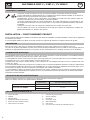 6
6
-
 7
7
-
 8
8
-
 9
9
-
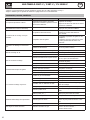 10
10
-
 11
11
-
 12
12
-
 13
13
-
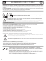 14
14
-
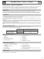 15
15
-
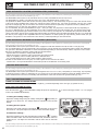 16
16
-
 17
17
-
 18
18
-
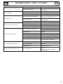 19
19
-
 20
20
-
 21
21
-
 22
22
-
 23
23
-
 24
24
-
 25
25
-
 26
26
-
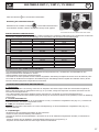 27
27
-
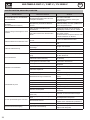 28
28
-
 29
29
-
 30
30
-
 31
31
-
 32
32
-
 33
33
-
 34
34
-
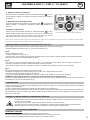 35
35
-
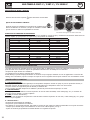 36
36
-
 37
37
-
 38
38
-
 39
39
-
 40
40
-
 41
41
-
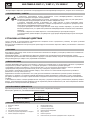 42
42
-
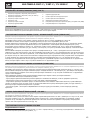 43
43
-
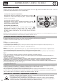 44
44
-
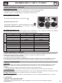 45
45
-
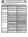 46
46
-
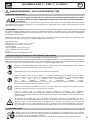 47
47
-
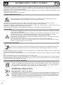 48
48
-
 49
49
-
 50
50
-
 51
51
-
 52
52
-
 53
53
-
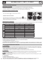 54
54
-
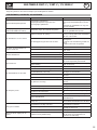 55
55
-
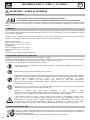 56
56
-
 57
57
-
 58
58
-
 59
59
-
 60
60
-
 61
61
-
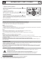 62
62
-
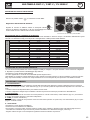 63
63
-
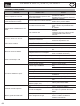 64
64
-
 65
65
-
 66
66
-
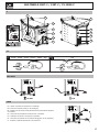 67
67
-
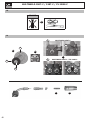 68
68
-
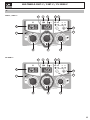 69
69
-
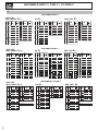 70
70
-
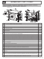 71
71
-
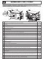 72
72
-
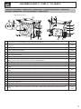 73
73
-
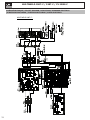 74
74
-
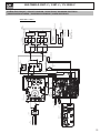 75
75
-
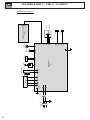 76
76
-
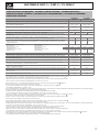 77
77
-
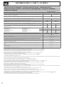 78
78
-
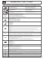 79
79
-
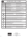 80
80


GYS MULTIWELD FV 220M-C El manual del propietario
- Categoría
- Sistema de soldadura
- Tipo
- El manual del propietario
en otros idiomas
- français: GYS MULTIWELD FV 220M-C Le manuel du propriétaire
- italiano: GYS MULTIWELD FV 220M-C Manuale del proprietario
- English: GYS MULTIWELD FV 220M-C Owner's manual
- Deutsch: GYS MULTIWELD FV 220M-C Bedienungsanleitung
- русский: GYS MULTIWELD FV 220M-C Инструкция по применению
- Nederlands: GYS MULTIWELD FV 220M-C de handleiding
Artículos relacionados
-
GYS MULTIWELD MIG/MAG and MMA Welding Machine Guía del usuario
-
-
-
-
-
-
GYS MULTIWELD FV 220M-C Ficha de datos
-
-
-
GYS INVERTER 3200 Ficha de datos