Kichler Lighting 12674AZ Manual de usuario
- Tipo
- Manual de usuario

INSTALLATION INSTRUCTIONS
LED Step Light
Models: 12672/CP300910 (dimmable), 12682/CP300917 (non-dimmable)
12673/CP300911 (dimmable), 12683/CP300918 (non-dimmable)
12674/CP300912 (dimmable), 12684/CP300919 (non-dimmable)
WARNING: Turn off power.
IMPORTANT: Before you start, NEVER attempt any work without
shutting off the electricity until the work is done.
a) Go to the main fuse or circuit breaker box in your home. Place
the main power switch in the “OFF” position.
b) Unscrew the fuse(s), or switch “OFF” the circuit breaker switch(s),
that control the power to the fixture or room that you are working in.
NOTES:
•Suitableforinteriordryordamplocationsonly.Notsuitableforexterior
use.
•Installation must comply with all local code and NEC requirements.
If you are not familiar with code requirements, installation by a
certified electrician is recommended.
•Suitableforconnectiontocopperbranchcircuitconductorsonly.
•Suitableforinsulatedwallorceilinglocations.(TypeIC)
•Dimmablemodelsmaybedimmedwithmostincandescent(triac)
or electronic low voltage dimmers.
•Thislightxturemustbeinstalledinasingle-gangreceptacleor
switch box (not supplied).
The box capacity must be 14 cubic inches or larger. Metal or
plastic boxes are acceptable.
INSTALLATION:
1. At the desired fixture location, mount the receptacle box. If wall
mounting, the box should be mounted horizontally.
2. For optimum light output when wall mounted, the receptacle box
centerline should be 18” above the floor.
3. Install 120 VAC 15 or 20 amp branch circuit electrical power into the
receptacle box.
4. For new construction, the drywall or wall surface must be in place
and preferably finished before the fixture can be installed.
5. Wireconnectionstothexturearemadeusingthe3push-inwire
connectors provided. These connectors are suitable for solid or
stranded copper conductors, #12 AWG to #20 AWG. Branch circuit
wires must have 1/2” of insulation cleanly removed from the ends.
Grip wire firmly and push each exposed conductor into an available
port on each connector until they are fully inserted. Match insulation
color from branch circuit wires to colors on fixture wires. Join black
wire to black, hite to white, and green or bare conductor to green.
6. Verify that each branch circuit wire is fully inserted to the back of the
connector.
7. Carefully push all wire and connectors into the back of the receptacle
box.
8. Place the fixture into the box and secure with the screws provided. If
wall mounting, note the fixture label that indicates which side of the
fixture must face up.
9. Place the trim plate over the upper flange, pivot down and secure
with set screw.
INSTRUCCIONES DE INSTALACIÓN
Luz de escalón de LED
Modelos: 12672/CP300910 (c/reductor), 12682/CP300917 (sin reductor)
12673/CP300911 (c/reductor), 12683/CP300918 (sin reductor), 12674/
CP300912 (c/reductor) 12684/CP300919 (sin reductor)
ADVERTENCIA: Apague la alimentación eléctrica.
IMPORTANTE: Antes de comenzar; NUNCA intente hacer ningún trabajo
sin apagar la alimentación eléctrica hasta que esté terminado el trabajo.
a) Vaya al fusible principal o al cortacircuitos de su casa.
Ponga el interruptor principal de alimentación en posición
“APAGADA”(“OFF”)
b) Destornilleel(los)fusible(s),o“APAGUE”losinterruptores
de circuito que controlan la alimentación eléctrica al
artefacto o al cuarto donde esté trabajando.
NOTAS:
•Adecuadosóloparalugaresdeinteriorhúmedososecos.Noes
adecuado para uso exterior.
•Lainstalacióndebesatisfacertodoslosrequisitosdeloscódigos
localesydelNEC.Siustednoestáfamiliarizadoconlosrequisitos
del código, se recomienda que la instalación la haga un electricista
licenciado.
•Adecuadosóloparaconexiónaconductoresdecircuitode
derivación de cobre.
•Adecuadoparalugaresdelcielorasooparaparedconaislamiento.
(Tipo IC)
•Losmodelosconreductoresdeintensidadluminosapuedenusarse
con la mayoría de los reductores de intensidad luminosa de bajo
voltaje electrónicos o con bombillas incandescentes (triac)
•Esteartefactoluminososedebeinstalarenunreceptáculodesalida
simpleoenlacajadedistribución(nosesuministra).Lacapacidad
delacajadebeserde14pulgadascúbicasomayor.Lascajasde
metalodeplásticosonaceptables.
INSTALACIÓN:
1. En el lugar donde se desee poner el artefacto, monte el tomacorriente.
Sisemontaenlapared,eltomacorrientesedebemontarhorizontalmente.
2. Para el rendimiento luminoso óptimo, cuando se monte en la pared,
el centro del tomacorriente debe estar 18” arriba del piso.
3. Instale la potencia eléctrica del circuito de derivación de 120 VAC de
15 ó 20 amperios en el tomacorriente.
4. Para una construcción nueva, la pared sin mortero o la superficie de
la pared debe estar lista y preferentemente acabada antes de que se
pueda instalar el artefacto.
5. Lasconexionesdealambresalartefactosepuedenhacerusando
los 3 conectores de alambre de presionar que se proveen. Estos
conectores son adecuados para conductores de cobre trenzados o
sólidos,desdeelNo.12AWGhastael20AWG.Losalambresdel
circuito derivado deben tener 1/2” de aislamiento quitado limpiamente
de los extremos. Firmemente sujete el alambre y empuje cada
conductor expuesto en el acceso de cada conector hasta que estén
insertados a fondo. Haga coincidir el color del aislamiento de cada
alambre del circuito de derivación con los colores de los alambres
del artefacto. Una el alambre negro al negro, el blanco al blanco y el
verde al conductor verde sin aislamiento.
6. Verifique que cada alambre del circuito de derivación esté insertado
a fondo en la parte posterior del conector.
7. Cuidadosamente empuje todos los alambres y conectores en la
parte posterior de la caja de derivación.
8. Ponga el artefacto en la caja y sujete con los tornillos que se
proveen.Sisemontaenlapared,notelaetiquetadelartefactoque
indicacuálladodelartefactodebemirarhaciaarriba.
9. Coloque la placa de adorno sobre el reborde superior, gire hacia
abajo y asegure con tornillo de presión.
IS-12672-USDateIssued:5/10/13
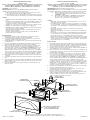
GREEN WIRE
ALAMBREVERDE
BLACKWIRE
ALAMBRENEGRO
WHITE WIRE
ALAMBREBLANCO
RECEPTACLEBOX
CAJADEDERIVACIÓN
FIXTURE
ARTEFACTO
Limited10YearWarranty.Formoredetails,visitwww.kichler.com
Garantíalimitadade10años.Paramásdetalles,visite:www.kichler.com
SETSCREW
TORNILLODEPRESIÓN
TRIMPLATE(STYLEMAYVARY)
PLACADEGUARNICIÓN
(ESTILOPUEDENVARIAR)
UPPERFLANGE
REBORDESUPERIOR
Transcripción de documentos
INSTALLATION INSTRUCTIONS LED Step Light Models: 12672/CP300910 (dimmable), 12682/CP300917 (non-dimmable) 12673/CP300911 (dimmable), 12683/CP300918 (non-dimmable) 12674/CP300912 (dimmable), 12684/CP300919 (non-dimmable) INSTRUCCIONES DE INSTALACIÓN Luz de escalón de LED Modelos: 12672/CP300910 (c/reductor), 12682/CP300917 (sin reductor) 12673/CP300911 (c/reductor), 12683/CP300918 (sin reductor), 12674/ CP300912 (c/reductor) 12684/CP300919 (sin reductor) WARNING: Turn off power. IMPORTANT: Before you start, NEVER attempt any work without shutting off the electricity until the work is done. a) Go to the main fuse or circuit breaker box in your home. Place the main power switch in the “OFF” position. b) Unscrew the fuse(s), or switch “OFF” the circuit breaker switch(s), that control the power to the fixture or room that you are working in. ADVERTENCIA: Apague la alimentación eléctrica. IMPORTANTE: Antes de comenzar; NUNCA intente hacer ningún trabajo sin apagar la alimentación eléctrica hasta que esté terminado el trabajo. a) Vaya al fusible principal o al cortacircuitos de su casa. Ponga el interruptor principal de alimentación en posición “APAGADA” (“OFF”) b) Destornille el (los) fusible(s), o “APAGUE” los interruptores de circuito que controlan la alimentación eléctrica al artefacto o al cuarto donde esté trabajando. NOTES: • Suitable for interior dry or damp locations only. Not suitable for exterior use. • Installation must comply with all local code and NEC requirements. If you are not familiar with code requirements, installation by a certified electrician is recommended. • Suitable for connection to copper branch circuit conductors only. • Suitable for insulated wall or ceiling locations. (Type IC) • Dimmable models may be dimmed with most incandescent (triac) or electronic low voltage dimmers. • This light fixture must be installed in a single-gang receptacle or switch box (not supplied). The box capacity must be 14 cubic inches or larger. Metal or plastic boxes are acceptable. INSTALLATION: 1. At the desired fixture location, mount the receptacle box. If wall mounting, the box should be mounted horizontally. 2. For optimum light output when wall mounted, the receptacle box centerline should be 18” above the floor. 3. Install 120 VAC 15 or 20 amp branch circuit electrical power into the receptacle box. 4. For new construction, the drywall or wall surface must be in place and preferably finished before the fixture can be installed. 5. Wire connections to the fixture are made using the 3 push-in wire connectors provided. These connectors are suitable for solid or stranded copper conductors, #12 AWG to #20 AWG. Branch circuit wires must have 1/2” of insulation cleanly removed from the ends. Grip wire firmly and push each exposed conductor into an available port on each connector until they are fully inserted. Match insulation color from branch circuit wires to colors on fixture wires. Join black wire to black, hite to white, and green or bare conductor to green. 6. Verify that each branch circuit wire is fully inserted to the back of the connector. 7. Carefully push all wire and connectors into the back of the receptacle box. 8. Place the fixture into the box and secure with the screws provided. If wall mounting, note the fixture label that indicates which side of the fixture must face up. 9. Place the trim plate over the upper flange, pivot down and secure with set screw. NOTAS: • Adecuado sólo para lugares de interior húmedos o secos. No es adecuado para uso exterior. • La instalación debe satisfacer todos los requisitos de los códigos locales y del NEC. Si usted no está familiarizado con los requisitos del código, se recomienda que la instalación la haga un electricista licenciado. • Adecuado sólo para conexión a conductores de circuito de derivación de cobre. • Adecuado para lugares del cielo raso o para pared con aislamiento. (Tipo IC) • Los modelos con reductores de intensidad luminosa pueden usarse con la mayoría de los reductores de intensidad luminosa de bajo voltaje electrónicos o con bombillas incandescentes (triac) • Este artefacto luminoso se debe instalar en un receptáculo de salida simple o en la caja de distribución (no se suministra). La capacidad de la caja debe ser de 14 pulgadas cúbicas o mayor. Las cajas de metal o de plástico son aceptables. INSTALACIÓN: 1. En el lugar donde se desee poner el artefacto, monte el tomacorriente. Si se monta en la pared, el tomacorriente se debe montar horizontalmente. 2. Para el rendimiento luminoso óptimo, cuando se monte en la pared, el centro del tomacorriente debe estar 18” arriba del piso. 3. Instale la potencia eléctrica del circuito de derivación de 120 VAC de 15 ó 20 amperios en el tomacorriente. 4. Para una construcción nueva, la pared sin mortero o la superficie de la pared debe estar lista y preferentemente acabada antes de que se pueda instalar el artefacto. 5. Las conexiones de alambres al artefacto se pueden hacer usando los 3 conectores de alambre de presionar que se proveen. Estos conectores son adecuados para conductores de cobre trenzados o sólidos, desde el No.12 AWG hasta el 20 AWG. Los alambres del circuito derivado deben tener 1/2” de aislamiento quitado limpiamente de los extremos. Firmemente sujete el alambre y empuje cada conductor expuesto en el acceso de cada conector hasta que estén insertados a fondo. Haga coincidir el color del aislamiento de cada alambre del circuito de derivación con los colores de los alambres del artefacto. Una el alambre negro al negro, el blanco al blanco y el verde al conductor verde sin aislamiento. 6. Verifique que cada alambre del circuito de derivación esté insertado a fondo en la parte posterior del conector. 7. Cuidadosamente empuje todos los alambres y conectores en la parte posterior de la caja de derivación. 8. Ponga el artefacto en la caja y sujete con los tornillos que se proveen. Si se monta en la pared, note la etiqueta del artefacto que indica cuál lado del artefacto debe mirar hacia arriba. 9. Coloque la placa de adorno sobre el reborde superior, gire hacia abajo y asegure con tornillo de presión. BLACK WIRE ALAMBRE NEGRO GREEN WIRE ALAMBRE VERDE RECEPTACLE BOX CAJA DE DERIVACIÓN WHITE WIRE ALAMBRE BLANCO UPPER FLANGE REBORDE SUPERIOR FIXTURE ARTEFACTO TRIM PLATE (STYLE MAY VARY) PLACA DE GUARNICIÓN (ESTILO PUEDEN VARIAR) SET SCREW TORNILLO DE PRESIÓN Date Issued: 5/10/13 Limited 10 Year Warranty. For more details, visit www.kichler.com Garantía limitada de 10 años. Para más detalles, visite: www.kichler.com IS-12672-US-
 1
1

Kichler Lighting 12674AZ Manual de usuario
- Tipo
- Manual de usuario
en otros idiomas
- English: Kichler Lighting 12674AZ User manual


