WARRANTY INFORMATION
PLEASE READ AND SAVE THESE IMPORTANT INSTRUCTIONS
Owner’s Guide
HPF650/650MC
HPF651/651MC
WARRANTY INFORMATION
Outdoor Patio Fan
Printed In China
FEATURES - OPERATIONS
ADJUSTMENT INSTRUCTIONS
TILT-ADJUSTMENT
Follow these instructions to tilt the Fan Head for upward angle air movement.
1. To change the tilting angle of the fan head, simply loosen the Tilt-Adjustment Knob (K) by turning it counter-
clockwise.
2. Move the fan head to the desired angle and firmly tighten the Tilt-Adjustment Knob (K) to lock into place.
CLEANING/MAINTENANCE INSTRUCTIONS
Follow these instructions to correctly and safely care for your fan. Please remember:
• Always unplug the fan before cleaning or disassembling.
• Do not allow water to drip on or into the fan motor housing.
• Do not use any of the following as a cleaner: gasoline, thinner, benzene.
FAN BLADE CLEANING
1. To access the fan blade, remove the front grill and securing screw.
2. Clean the fan blade, front and rear grills with a soft, moist cloth.
3. Replace blade, tighten screw and securely fasten the front grill.
FAN HEAD, BASE AND POLE CLEANING
Using a soft, moist cloth, with or without a mild soap solution, carefully clean the fan base, pole and head. Please use
caution around the motor housing area. Do not allow the motor or other electrical components to be exposed to water.
FAN STORAGE INSTRUCTIONS
Your fan should be stored indoors in the off-season.
Please DO NOT attempt to open or repair the fan. Please see the Warranty Information section or
contact consumer service at 1-800-546-5637.
INFORMACIÓN DE LA GARANTÍA INFORMACIÓN DE LA GARANTÍA
INSTRUCCIONES PARA REPARACIONES
1. NO intente reparar o ajustar ninguna función eléctrica o mecánica de esta unidad. El hacerlo invalidará la garantía.
2. Si tuviese cualquier pregunta sobre la operación de esta unidad o considera que la misma requiere alguna
reparación, escríbale a nuestro departamento de servicios al cliente.
3. Si necesita cambiar la unidad, devuélvala en su caja original, con el recibo de compra, a la tienda donde la haya
comprado. Si devuelve la unidad más de 30 días después de la fecha de compra, vea la garantía adjunta.
4. Si tiene algún comentario o pregunta acerca del funcionamiento de la unidad, o cree que debe ser reparada, escriba
a nuestro departamento de servicio al consumidor o visite nuestro sitio de Internet en
www.holmesproducts.com.
SUNBEAM PRODUCTS, INC. OPERANDO COMO JARDEN CONSUMER SOLUTIONS
303 NELSON AVENUE
NEOSHO, MO 64850
Grape o adjunte su recibo de compra a este manual para no perderlo. También, tómese un momento para anotar a
continuación el nombre/dirección del negocio y la fecha de compra.
NOMBRE DE LA TIENDA:
DIRECCIÓN:
FECHA DE COMPRA:
(GRAPE EL RECIBO AQUÍ)
9100010008157 HPF650/651/MC06ESM1 Impreso en China
Manual del propietario
LEA Y CONSERVE ESTAS INSTRUCCIONES IMPORTANTES
Ventilador para Jardines
y Patios Exteriores
HPF650/650MC
HPF651/651MC
CARACTERÍSTICAS Y FUNCIONAMIENTO
INSTRUCCIONES PARA LA REGULACIÓN
REGULACIÓN DE LA INCLINACIÓN
Siga estas instrucciones al inclinar el cabezal del ventilador para que el aire circule hacia arriba.
1. Para cambiar el ángulo de inclinación del cabezal, simplemente afloje la perilla reguladora de inclinación (K)
girándola en sentido contrario a las manecillas del reloj.
2. Mueva el cabezal al ángulo deseado y fíjelo ajustando firmemente la perilla reguladora de inclinación (K).
INSTRUCCIONES PARA LA LIMPIEZA Y EL MANTENIMIENTO
Siga estas instrucciones para el cuidado correcto y seguro del ventilador, recordando lo siguiente:
• Siempre desenchufe el ventilador antes de limpiarlo o desmontarlo.
• No permita que gotee agua sobre ni dentro del casco del motor del ventilador.
• No use limpiadores tales como gasolina, diluyente de pintura, bencina, etc.
LIMPIEZA DE LA HÉLICE DEL VENTILADOR
1. Para tener acceso a la hélice, saque la rejilla frontal y el tornillo de sujeción.
2. Limpie la hélice y las rejillas con un trapo suave húmedo.
3. Reinstale la hélice, ajuste el tornillo, reinstale la rejilla frontal y asegúrela.
LIMPIEZA DEL CABEZAL, LA BASE Y EL POSTE
Limpie la base, el poste y el cabezal cuidadosamente con un trapo humedecido sólo con agua o con una solución de
jabón. Tenga cuidado al limpiar alrededor del motor. No exponga el motor ni otros componentes eléctricos al agua.
ALMACENAJE DEL VENTILADOR
Al final de la temporada guarde el ventilador en un ambiente interior.
NO intente abrir o reparar el ventilador. Por favor, vea la garantía para las instrucciones de reparación
o llame al servicio de atención al cliente al 1-800-546-5637.
Fan head moves during operation. Tilt Adjustment Knob not tightened
properly.
Tighten Tilt Adjustment Knob by
turning it clockwise after Fan Head
is in desired position.
Fan will not operate even though I
am turning on the fan with the
Speed Control Knob.
Fan is not plugged in. Plug the power cord into a 120 V AC
Outlet. Be sure the Speed Control
Knob is in the off position prior to
plugging in the fan.
All Parts listed in Figure 1 are not
included.
Parts missing or lost. Contact our Consumer Service
Department. (see Warranty section)
ISSUE POTENTIAL CAUSE POTENTIAL SOLUTION
El cabezal del ventilador se mueve
durante el funcionamiento.
La perilla reguladora de inclinación
no está ajustada correctamente.
Ajuste la perilla reguladora de inclinación
girándola en el sentido de las manecillas
del reloj después de que el cabezal del
ventilador esté en la posición deseada.
El ventilador no funcionará aunque
lo prenda con la perilla del control
de velocidad.
El ventilador no está enchufado. Enchufe el cable de electricidad en un
tomacorriente de 120 V de CA.
Asegúrese de que la perilla del control
de velocidad esté en la posición de
apagado antes de conectar el ventilador.
Las piezas detalladas en la Figura 1
no están incluidas.
Faltan piezas o se perdieron piezas. Póngase en contacto con nuestro
Departamento de Servicio al Cliente.
(vea la GARANTIA)
PROBLEMA CAUSA POTENCIAL POSIBLE SOLUCION
SERVICE INSTRUCTIONS
1. DO NOT attempt to repair or adjust any electrical or mechanical functions on this unit. Doing so will void the
warranty.
2. If you have any questions regarding this unit’s operation or believe any repair is necessary, please write to our
Consumer Service Department.
3. If you need to exchange the unit, please return it in its original carton, with a sales receipt, to the store where you
purchased it. If you are returning the unit more than 30 days after the date of purchase, please see the enclosed
warranty.
4. If you have any other questions or comments, see our correspondence below or visit our website at
www.holmesproducts.com.
SUNBEAM PRODUCTS, INC. DOING BUSINESS AS JARDEN CONSUMER SOLUTIONS
303 NELSON AVENUE
NEOSHO, MO 64850
For your own records, staple or attach your sales receipt to this manual. Also, please take a moment to write the store
name/location and date purchase below.
STORE NAME:
LOCATION:
DATE PURCHASED:
(STAPLE RECEIPT HERE)
3 YEAR LIMITED WARRANTY
Sunbeam Products, Inc.
doing business as
Jarden Consumer Solutions or if in Canada, Sunbeam Corporation (Canada)
Limited doing business as Jarden Consumer Solutions (collectively “JCS”) warrants that for a period of three years from
the date of purchase, this product will be free from defects in material and workmanship. JCS, at its option, will repair
or replace this product or any component of the product found to be defective during the warranty period. Replacement
will be made with a new or remanufactured product or component. If the product is no longer available, replacement
may be made with a similar product of equal or greater value. This is your exclusive warranty. Do NOT attempt to
repair or adjust any electrical or mechanical functions on this product. Doing so will void this warranty.
This warranty is valid for the original retail purchaser from the date of initial retail purchase and is not transferable.
Keep the original sales receipt. Proof of purchase is required to obtain warranty performance. JCS dealers, service centers,
or retail stores selling JCS products do not have the right to alter, modify or any way change the terms and conditions of this
warranty.
This warranty does not cover normal wear of parts or damage resulting from any of the following: negligent use or
misuse of the product, use on improper voltage or current, use contrary to the operating instructions, disassembly, repair
or alteration by anyone other than JCS or an authorized JCS service center. Further, the warranty does not cover: Acts
of God, such as fire, flood, hurricanes and tornadoes.
What are the limits on JCS’s Liability?
JCS shall not be liable for any incidental or consequential damages caused by the breach of any express, implied or
statutory warranty or condition.
Except to the extent prohibited by applicable law, any implied warranty or condition of merchantability or fitness for a
particular purpose is limited in duration to the duration of the above warranty.
JCS disclaims all other warranties, conditions or representations, express, implied, statutory or otherwise.
JCS shall not be liable for any damages of any kind resulting from the purchase, use or misuse of, or inability to use the
product including incidental, special, consequential or similar damages or loss of profits, or for any breach of contract,
fundamental or otherwise, or for any claim brought against purchaser by any other party.
Some provinces, states or jurisdictions do not allow the exclusion or limitation of incidental or consequential damages or
limitations on how long an implied warranty lasts, so the above limitations or exclusion may not apply to you.
This warranty gives you specific legal rights, and you may also have other rights that vary from province to province,
state to state or jurisdiction to jurisdiction.
How to Obtain Warranty Service
In the U.S.A.
If you have any question regarding this warranty or would like to obtain warranty service, please call 1-800-546-5637
and a convenient service center address will be provided to you.
In Canada
If you have any question regarding this warranty or would like to obtain warranty service, please call 1-800-546-5637
and a convenient service center address will be provided to you.
In the U.S.A., this warranty is offered by Sunbeam Products, Inc
doing business as
Jarden Consumer Solutions located in
Boca Raton, Florida 33431. In Canada, this warranty is offered by Sunbeam Corporation (Canada) Limited doing
business as Jarden Consumer Solutions, located at 5975 Falbourne Street, Mississauga, Ontario L5R 3V8. If you have
any other problem or claim in connection with this product, please write our Consumer Service Department. PLEASE
DO NOT RETURN THIS PRODUCT TO ANY OF THESE ADDRESSES OR TO THE PLACE OF PURCHASE.
© 2006 Sunbeam Products, Inc.doing business as Jarden Consumer Solutions. All Rights Reserved.
© 2006 Sunbeam Products, Inc. operando como Jarden Consumer Solutions. Todos los derechos reservados
GARANTÍA LIMITADA DE 3 AÑO
Sunbeam Products, Inc. operando como Jarden Consumer Solutions o en Canadá, Sunbeam Corporation (Canada) Limited
operando como Jarden Consumer Solutions (colectivamente "JCS") garantiza que durante un período de tres años a partir de
la fecha de compra, este producto no presentará defectos de materiales o de fabricación. JCS, a su criterio, reparará o
reemplazará este producto o cualquier componente del producto que presente defectos durante el período de garantía. El
reemplazo se realizará con un producto o componente nuevo o reacondicionado. Si no se puede conseguir el mismo producto,
se lo reemplazará por otro similar de igual o mayor valor. Esta es su garantía exclusiva. NO intente reparar o ajustar ninguna
función eléctrica o mecánica de este producto. El hacerlo invalidará esta garantía.
Esta garantía es válida para el comprador original a partir de la fecha original de compra y no es transferible. Conserve el
recibo original de compra. Necesitará un comprobante de compra para obtener servicio de garantía. Los distribuidores de JCS,
centros de servicio o tiendas de venta de productos JCS no tienen derecho a modificar, alterar o de cambiar de ninguna forma
los términos y condiciones de esta garantía.
Esta garantía no cubre el desgaste normal de las partes o el daño debido a cualquiera de las siguientes condiciones: Uso
negligente o abuso del producto, utilización con voltaje o corriente inadecuados, uso contrario a las instrucciones de operación,
desarmado, reparación o alteración por alguien que no sea JCS o un centro de servicio autorizado por JCS. Además, la garantía
no cubre: Casos fortuitos, como incendios, inundaciones, huracanes y tornados.
¿Cuáles son las limitaciones de responsabilidad de JCS?
JCS no se hará responsable por ningún daño indirecto, incidental o consecuente causado por el incumplimiento de cualquier
garantía o condición explícita, implícita o legal.
Excepto en los casos prohibidos por las leyes vigentes, toda garantía o condición de comerciabilidad o aptitud para un fin
determinado implícita queda limitada en su duración al término de esta garantía.
JCS renuncia a cualquier otra garantía, condición o representación, explícita, implícita, legal o de cualquier otro tipo.
JCS no será responsable por ningún daño de ninguna clase causado por la compra, uso o abuso del producto, o por la
inhabilidad de usar el producto incluyendo daños incidentales, especiales, indirectos o similares o por lucro cesante, o por
cualquier incumplimiento de contrato, fundamental o no, o por cualquier reclamo presentado contra el comprador por cualquier
otra persona.
Algunas provincias, estados o jurisdicciones no permiten la exclusión o limitación de daños incidentales o indirectos o la
limitación con respecto a cuanto dura una garantía implícita, por lo tanto las exclusiones o limitaciones anteriores pueden no
aplicarse en su caso.
Esta garantía le otorga derechos legales específicos, y usted puede también tener otros derechos los que varían de estado a
estado, de provincia a provincia o de jurisdicción a jurisdicción.
Cómo obtener servicio de garantía
En los Estados Unidos
Si tiene alguna pregunta con respecto a esta garantía o desea obtener servicio de garantía, llame al 1-800-546-5637 y le
daremos la dirección del centro de servicio más conveniente para usted.
En Canadá
Si tiene alguna pregunta con respecto a esta garantía o desea obtener servicio de garantía, llame al 1-800-546-5637 y le
daremos la dirección del centro de servicio más conveniente para usted.
En los Estados Unidos, esta garantía se ofrece a través de Sunbeam Products, Inc. operando como Jarden Consumer Solutions
ubicado en Boca Raton, Florida 33431. En Canadá, esta garantía se ofrece a través de Sunbeam Corporation (Canada) Limited
operando como Jarden Consumer Solutions ubicado en 5975 Falbourne Street, Mississauga, Ontario L5R 3V8. Si tiene cualquier
otro problema o reclamo con relación a este producto, por favor escriba a nuestro Departamento de Servicio al Consumidor.
POR FAVOR, NO RETORNE ESTE PRODUCTO A NINGUNA DE ESAS DIRECCIONES O AL LUGAR DONDE LO HAYA COMPRADO.
HPF650/651/MC06ESM1.QXD 9/29/06 15:15 Page 1

• Phillips Head Screws (R)
•Washers (T)
1. Place the Lower Pole assembly (L), which includes the
Lower Pole with the Mounted Weight and Conical Base
(as shipped in Box 1) on the floor, lying down on its side.
2. Slide the Leg Bracket (P) over the end of the Lower
Pole Assembly (L). Be sure the Leg Bracket holes line
up with the screw holes on the Lower Pole Assembly. (See
Figure 2)
3. Screw 3 of the Phillips Head Screws (R ) through each
hole (3) in the leg bracket, into the Lower Pole
Assembly (L). (See Figure 3)
4. Place the Conical Base End Cap (N) over the Leg
Bracket (P) so that the slots fit around the Leg Bracket.
5. Secure the Conical Base End Cap (N) to the Lower Base
Assembly (L) using one (1) Phillips Head Screw (R).
(See Figure 4)
6. With the leg and base assembly still lying on the floor,
make sure one of the three Legs (O) is facing up,
position one of the three legs so that the end with one
hole aligns with the hole in the Lower Base Assembly
Flange (L). Secure the Leg (O) to the assembly using
three (3) Bolts ( S ) and Washers (T).(See Figure 5)
NOTE: the end with two (2) holes will line up
with the two (2) holes in the Leg Bracket (P).
7. Rotate and repeat this for each of the three legs.
NOTE: When all three legs are attached, go back and
make sure all the screws are tight.
8. Stand the unit upright so the legs are on the floor.
9. Take the Upper Pole (Q) and insert into the Lower Base
Assembly (L) with the recessed slot on the top of the
upper pole showing. (See Figure 6)
10. Align the holes and secure with Phillips Head Screws
(R).
11. Slide the Decorative Cap (M) over the Upper Pole (Q)
Line up and insert the posts of the Decorative Cap (M)
with the holes in the Flange (L). Turn the Decorative
Cap clockwise to lock. Refer to Figure 6.
NOTE: The Holmes
®
logo will be facing the front of
the fan. Now you are ready to assembly the fan head.
FAN HEAD ASSEMBLY
You will need the following parts:
• Motor Housing (H)
• Front Grill (B)
• Fan Blade (C)
•Fan Blade Securing Screw (D)
BOX LISTING
BOX 1
• Conical Base and Lower Pole with Mounted Weight and
Flange
BOX 2
• Front Grill
• Rear Grill
• Fan Blade
BOX 3
• Leg Bracket
• Upper Pole
BOX 4
•Hardware Kit
- Wrench
- Phillips Head Screws (6)
- Leg Assembly Mounting Bolts (9)
- Flat Washers (9)
• Conical Base Decorative Cap
• Conical Base End Cap
•* INCLUDED WITH HPF650MC/ HPF651MC ONLY.
* Misting Kit Accessory
* Storage Cover
BOX 5
• Motor Housing with Rear Grill Mounting Nut
BOX 6
• Legs (3)
ASSEMBLY INSTRUCTIONS
Approximate assembly time: 20-30 minutes
Tools Required: Wrench (Provided in Hardware Kit) &
Phillips Head Screwdriver.
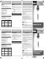
Carefully unpack all contents from the carton. Please note
the location of all parts as above.
ASSEMBLY
• Carefully unpack and lay out all of the parts described
in Figure 1 and Figure 11 (Hardware Kit).
• Ensure you have all parts.
• If you do not, please contact our Consumer Service
Dept. (see Warranty Section in this manual) or visit our
website at www.holmesproducts.com.
LEG & BASE ASSEMBLY
You will need the following parts:
• Legs – all 3 (O)
• Leg Bracket (P)
• Leg Assembly Mounting Bolts (S)
• Conical Base and Lower Pole Assembly with Mounted
Weight and Flange (L) (shipped together)
• Conical Base Decorative Cap (M)
• Upper Pole (Q)
• Conical Base End Cap (N)
PLEASE READ AND SAVE THESE
IMPORTANT SAFETY INSTRUCTIONS
FEATURES - OPERATIONS
When using electrical appliances, basic safety precautions
should always be followed to reduce the risk of fire,
electric shock, and injury to persons, including the
following:
1. Read all instructions before using this appliance.
2. Use fan only for purposes described in the instruction
manual.
3. To protect against electrical shock do not immerse unit,
plug or cord in water or spray with liquids and plug
the appliance directly into a 120V AC electrical outlet.
4. Close supervision is necessary when any appliance is
used by or near children.
5. Unplug from outlet when not in use, when moving fan
from one location to another, before putting on or
taking off parts and before cleaning.
6. Avoid contact with moving parts.
7. Do not operate in the presence of explosive and/or
flammable fumes.
8. To avoid fire hazard, NEVER place the cord under rugs
or any parts near an open flame, cooking or other
heating appliance.
9. Do not operate any appliance with a damaged cord or
plug after the appliance malfunctions, or has been
dropped/damaged in any manner.
10. The use of attachments not recommended or sold by
the appliance manufacturer may cause hazards.
11. Do not let the cord hang over the edge of a table,
counter or come in contact with hot surfaces or leave
exposed to high traffic areas.
12. To disconnect, grip plug and pull from wall outlet.
Never yank on cord.
13. Always use on a dry, level surface.
14. Do not operate fan until fully assembled with all parts
properly in place.
15. This product is intended for household use ONLY and
not for commercial or industrial applications.
16. WARNING: To reduce the risk of electrical shock and
injury to persons, do not use in window.
17. WARNING: To reduce the risk of fire or electric
shock, DO NOT use this fan with any solid-state speed
control device.
Thank you for purchasing this Holmes
®
product. We
understand the value of quality and are committed to
making superior products that stand the test of time. We
trust this product will exceed your expectations of quality
and reliability. We hope that you enjoy this product and
will consider purchasing another Holmes
®
product in the
future.
To see our full product line or if you have any questions or
comments about this product, please visit our website at:
www.holmesproducts.com.
PLEASE READ AND SAVE
THESE IMPORTANT SAFETY
INSTRUCTIONS
CONSUMER SAFETY INFORMATION
NOTE: This is an electrical appliance and requires
attention when in use.
NOTE: DO NOT block air intake grill or filtered air outlet.
CAUTION: Use Only with GFCI Protected Receptacles.
FEATURES - OPERATIONS
This product is for use on 120 volts. The cord has a plug (A) as shown. An adapter
(C) is available for connecting three-blade grounding-type plugs to two-slot
receptacles (B). The green grounding lug extending from the adapter must be
connected to a permanent ground such as a properly grounded outlet box. The
adapter should not be used if a three-slot grounded receptacle is available.
FEATURES - OPERATIONS
•Rear Grill (F)
• Rear Grill Mounting Nut (E)
• Phillips Head Screws (R)
1. Place the Motor Housing (H) over the Upper Pole (
Align the stem of the Motor Housing with the notch in
the Upper Pole (Q). )
2. Secure the Motor Housing to the Upper Pole using one
of the Phillips Head Screws ( R ). (See Figure 7)
3. Remove the Rear Grill Mounting Nut (E) from the
Motor Housing (H).
4. Place the Rear Grill (F) over the Motor Shaft (G) of the
Motor Housing. Line up the cross spokes on the Rear
Grill (F) with the 4 mounting slots on the Motor
Housing.
5. Place the Rear Grill Mounting Nut (E) over the Rear
Grill (F) and turn clockwise to tighten. (See Figure 8)
6. Slide the Fan Blade (C ) over the Motor Shaft (G) with the
Fan Blade Securing Screw (D) facing toward the Rear Grill
(F). Align the Fan Blade Securing Screw over the recessed
groove in the Motor Shaft (G) until it is firmly in place.
7. Tighten the Fan Blade Securing Screw (D) into the
Motor Shaft (G) so that the Fan Blade is secure. (See
Figure 9)
8. Pick up the Front Grill (B) and release all Grill Clips
(U).
9. Hold Front Grill (B) with Hanging Bracket positioned
at the top. (See Figure 10)
10. With the Hanging Bracket positioned at the top of the
grill, align the Front and Rear Grills so the grill spokes
match up. Lock the two grills in place by pressing the
Grill Clips (U) down over both grills.
MISTING KIT ASSEMBLY INSTRUCTIONS
1. Before attaching misting kit, please ensure that the
fan is in the off position.
2. Unwind misting kit nozzle.
3. Attach the misting nozzles to the fan by snapping the
clip located behind each misting nozzle to the spokes
of the front grill. (See Figure 12, 13)
4. Attach the misting kit hose to a standard garden hose.
(See Figure 14)
5. Turn water on and return to the fan.
6. Turn fan on and enjoy natural evaporative cooling process.
OPERATING INSTRUCTIONS
1. Set fan base on a dry, level surface.
2. Plug cord into any standard 120 volt AC outlet. Please
make sure the Speed Control Knob (I) is in the OFF
position. Selector (Speed) Control is located at the rear
of the Fan Motor Housing.
3. The SPEED is adjusted by turning the control knob to
the desired setting, O-III-II-I.
4. The OSCILLATION Control Knob (J) is located on the
top of the Fan Motor Housing (H). To start oscillation,
push Oscillation Control Knob (J) down. To stop
oscillation, pull Oscillation Control Knob (J) up.
A. Grill Plate
B. Front Grill
C. Fan Blade
D. Fan Blade Securing
Screw
E. Rear Grill Mounting Nut
F. Rear Grill
G. Motor Shaft
H. Motor Housing
I. Speed Control Knob
(not shown)
J. Oscillation Control Knob
K. Tilt Adjustment Knob
L. Conical Base with Lower
Pole with Mounted
Weight and Flange
M. Conical Base Decorative
Cap
N. Conical Base End Cap
O. Legs (3)
P. Leg Bracket
Q. Upper Pole
R. Phillips Head Screws (6)
S. Leg Assembly Bolts (9)
T. Washers (9)
U. Grill Clips
Figure 1
B
F
C
J
H
Q
N
O
D
G
K
M
R
E
A
U
L
S & T
P
I
Figure 2
Figure 3
Figure 4
Fig. 5
S/T (9)
Figure 5
Fig. 6
R (1)
Fig. 7
R (1)
Figure 6
Figure 7
Figure 9
Figure 10
Fig. 8
Figure 8
Figure 11
Phillips Head Screws (6)
Leg Assembly Bolts (9)
Washers (9)
LEA Y CONSERVE ESTAS INSTRUCCIONES
IMPORTANTES DE SEGURIDAD
Siempre que se usen artefactos eléctricos, se deben tomar
precauciones básicas de seguridad, incluyendo las
siguientes:
1. Lea todas las instrucciones antes de usar este
artefacto.
2. Sólo utilice el ventilador para el propósito descrito en
este manual.
3. Para evitar los riesgos de choque eléctrico, no sumerja
la unidad, el enchufe ni el cordón en agua ni les rocíe
líquidos. Enchufe el artefacto directamente a un
tomacorriente de 120 V de CA.
4. Se necesita supervisión estrecha cuando los niños usen
cualquier artefacto o se usen cerca de ellos.
5. Siempre desenchufe el ventilador cuando no esté en
uso, antes de moverlo a otro lugar, instalarle o
quitarle piezas o limpiarlo.
6. Evite el contacto con las piezas movibles.
7. NO opere esta unidad en presencia de gases o vapores
explosivos y/o inflamables.
8. Para evitar el riesgo de incendio NUNCA coloque el
cordón debajo de alfombras ni parte alguna cerca de
llamas abiertas, hornillas ni otros artefactos que
generen calor.
9. No opere artefacto alguno con el cordón o el enchufe
dañados, después de haber funcionado mal, de
haberse caído o dañado de cualquier forma.
10. El uso de accesorios o dispositivos no recomendados o
vendidos por el fabricante puede generar riesgos.
11. No permita que el cordón cuelgue de la mesa o
mostrador, que haga contacto con superficies calientes,
ni lo deje expuesto en áreas de mucho tránsito.
12. Para desenchufar el ventilador, jale del enchufe,
nunca del cordón.
13. Siempre colóquelo sobre una superficie seca y
nivelada.
14. No opere el ventilador hasta que esté totalmente
ensamblado y con todas sus piezas instaladas
adecuadamente en su lugar.
15. Este artefacto sólo es para uso doméstico y no para
uso comercial ni industrial.
16. ADVERTENCIA: Para reducir el riesgo de incendio,
choque eléctrico o lesiones personales, NO lo coloque
en ventanas, NI use dispositivos de estado sólido para
control de velocidad.
17. ADVERTENCIA: Para reducir el riesgo de incendio,
choque eléctrico o lesiones personales, NO lo coloque
en ventanas, NI use dispositivos de estado sólido para
control de velocidad.
Gracias por comprar este producto Holmes
®
. Nosotros
entendemos el valor de la calidad y nos comprometemos a
hacer productos superiores que soportan el paso del
tiempo. Confiamos que este producto superará sus
expectativas de calidad y confiabilidad. Esperamos que
disfrute este producto y que considere adquirir otros
productos Holmes
®
en el futuro. Para ver nuestra línea
completa de productos o si tiene alguna pregunta o
comentario acerca de este producto,visite nuestro sitio
Web: www.holmesproducts.com.
LEA Y CONSERVE ESTAS
INSTRUCCIONES
IMPORTANTES DE SEGURIDAD
INFORMACIÓN DE SEGURIDAD PARA EL
CONSUMIDOR
NOTA: Éste es un artefacto eléctrico y requiere atención
durante su uso.
NOTA: NO bloquee la rejilla de entrada de aire.
PRECAUCIÓN: Utilice solamente en receptáculos
protegidos GFCI.
Este artefacto se usa con corriente de 120 voltios.El cordón tiene un enchufe (A)
como se muestra. Se dispone de un adaptador (C) para conectar enchufes de tres
espigas para conexión a tierra a tomacorriente de dos orificios (B). La pestaña
verde para conexión a tierra que sobresale del adaptador debe conectarse
permanentemente a tierra, como a la caja de un tomacorriente debidamente
conectado a tierra. No debe utilizarse el adaptador si se dispone de un
tomacorriente de tres orificios conectado a tierra.
CARACTERÍSTICAS Y FUNCIONAMIENTO CARACTERÍSTICAS Y FUNCIONAMIENTO CARACTERÍSTICAS Y FUNCIONAMIENTO
CONTENIDO DE LAS CAJAS
CAJA 1
• Base con la sección inferior del poste, la pesa y la
brida instaladas (se despacha como un conjunto)
CAJA 2
• Rejilla frontal
• Rejilla posterior
• Hélice
CAJA 3
• Soporte de las patas
• Sección superior del poste
CAJA 4
• Juego de elementos de fijación
- Llave de tuercas
- Tornillos con cabeza de ranura en cruz (6)
- Pernos para fijación de las patas (9)
- Arandelas planas (9)
•Tapa cónica decorativa de la base
•Tapa cónica del extremo de la base
•* INCLUIDO SÓLO EN EL MODELO HPF650MC/
HPF651MC
* Juego atomizador
* Funda para guardar
CAJA 5
• Motor en su casco y tuerca sujetadora de la rejilla
posterior
CAJA 6
• Patas (3)
INSTRUCCIONES DE ENSAMBLAJE
Tiempo aproximado de ensamblaje: 20 a 30 minutos
Herramientas requeridas: Llave de tuercas (incluida en el
juego de elementos de fijación) y atornillador de punta en
cruz.
Desempaque el contenido de las cajas y ubique todas las
piezas según lo indicado anteriormente.
ENSAMBLAJE
• Desempaque todas las piezas cuidadosamente e
identifíquelas contra las Figuras 1 y 11.
• Cerciórese de tener todas las piezas.
• Si so estuviesen completas, comuníquese con nuestro
Dpto. de Servicios al Cliente (vea la sección de la
Garantía en este manual) o visítenos en la internet
www.holmesproducts.com
ENSAMBLAJE DE LAS PATAS Y LA BASE
Necesita las siguientes piezas:
• Las 3 patas (O)
• Soporte de patas (P)
• Pernos para montaje de las patas (S)
• Base con sección inferior del poste, pesa y brida (L) (se
despachan ensambladas)
•Tapa cónica decorativa de la base (M)
• Sección superior del poste (Q)
•Tapa cónica del extremo de la base (N)
•Tornillos con cabeza en cruz (R)
• Arandelas (T)
1. Coloque la base (L) que incluye la sección inferior del
poste, y la pesa (como vino en la caja 1) en forma
horizontal sobre el piso.
2. Deslice el soporte de las patas (P) en el extremo
inferior de la base (L), alineando los agujeros. (Vea la
Figura 2).
3. Instale 3 de los tornillos de cabeza en cruz (R) uno en
cada agujero (3) del soporte de las patas y en la base
(L) (Vea la Figura 3).
4. Instale la tapa cónica del extremo de la base (N) con sus
ranuras alrededor de los dedos del soporte de las patas
(P).
5. Asegure la tapa cónica (N) en el extremo inferior de
la base (L) con un (1) tornillo con cabeza en cruz (R).
6. Con la pata y la base ensamblada y aún colocadas en
el piso en posición horizontal, asegúrese de que una
de las tres patas (O) quede hacia arriba; posicione una
de las tres patas de manera que el extremo con el
agujero quede alineado con el agujero de la brida
ensamblada en la parte inferior de la base(L).
NOTA: El extremo de la pata con dos (2)
orificios se alinea con los dos (2) orificios en el
soporte de las patas (P).
7. Rote el conjunto y repita el procedimiento para las
otras dos patas. NOTA: Cuando las tres patas estén
instaladas, asegúrese que todos los pernos y tornillos
estén bien ajustados.
8. Ponga la unidad de pie con las patas sobre el piso.
9. Inserte la sección superior del poste (Q) en la base (L)
haciendo que se vea la ranura encima de la sección
superior del poste. (Vea la Figura 6)
10. Alinee los orificios y asegure con los tornillos con
cabeza en cruz (R).
11. Deslice la tapa decorativa (M) sobre la sección superior
del poste (Q), alinee e inserte los postes de la cubierta
decorativa (M) procurando que coincidan con los
agujeros de la brida (L). Gire la tapa decorativa en
sentido a las manecillas del reloj para asegurarla. Vea
la figura 6.
NOTA: El logotipo de Holmes
®
quedará hacia el
frente del ventilador (Vea la Figura 6). Ahora ya se
puede comenzar a ensamblar el cabezal del
ventilador.
ENSAMBLAJE DEL CABEZAL
Necesita las siguientes piezas:
• Motor (H)
• Rejilla frontal (B)
• Hélice (C)
•Tornillo de fijación de la hélice (D)
• Rejilla posterior (E)
•Tuerca de montaje de la rejilla posterior (E)
•Tornillos con cabeza en cruz (R)
1. Coloque el motor (H) sobre el poste, alineando su clavija en
el casco con la ranura en la sección superior del poste (Q).
2. Asegure el motor al poste con uno de los tornillos con
cabeza en cruz (R). (Vea la Figura 7).
3. Saque la tuerca (E) para montaje de la rejilla posterior
que está en el eje del motor (H).
4. Coloque la rejilla posterior (F) en el eje (G) del motor
alineando los rayos cruzados de la rejilla con las 4
ranuras de montaje en el casco del motor.
5. Instale la tuerca de montaje (E) en el eje del motor (G) y
sobre la rejilla posterior (F), y ajústela girándola en el
sentido de las manecillas reloj. (Vea la Figura 8).
6. Deslice la hélice (C) en el eje (G) del motor con su tornillo
de sujeción (D) hacia la rejilla posterior (F). Alinee el
tornillo de sujeción (D) con la ranura en el eje (G) del
motor hasta que quede firme en posición.
7. Asegure la hélice (C) en el eje (G) del motor ajustando el
tornillo de sujeción (D). (Vea la Figura 9).
8. Tome la Rejilla Frontal (B) y suelte los (U) sujetadores de
las rejillas.
9. Sostenga la rejilla frontal (B) con el soporte colgador
hacia arriba (Vea la Figura 10).
10. Alinee los rayos de las dos rejillas y asegúrelas en
posición presionando los sujetadores (U) hacia abajo
sobre ambas rejillas.
INSTRUCCIONES PARA EL CONJUNTO
ATOMIZADOR
1. Antes de instalar el conjunto atomizador, cerciórese
que el ventilador esté apagado.
2. Desenrosque la boquilla del atomizador.
3. Instale las boquillas atomizadoras en el ventilador
enganchando el sujetador detrás de cada boquilla a
los rayos de la rejilla frontal. (Vea la Figura 12, 13)
4. Instale la manguera del atomizador a una manguera
estándar de jardín. (Vea la Figura 14)
5. Abra la llave del agua y regrese al ventilador.
6. Encienda el ventilador y disfrute de un proceso
evaporizador natural.
INSTRUCCIONES DE OPERACIÓN
1. Coloque la base en una superficie seca y nivelada.
2. Enchufe el cordón en cualquier tomacorriente
estándar de 120 voltios de CA. Cerciórese que el
ventilador esté en la posición de apagado (OFF). El
Selector de velocidades está localizado en la parte
posterior del casco del motor.
3. La VELOCIDAD se regula girando la perilla a la
posición deseada de O-III-II-I.
4. La Perilla de Control de OSCILACIÓN (J) está sobre el
casco del motor (H). Para iniciar la oscilación, presione
la Perilla (J) y levántela para detener la oscilación.
A. Placa de la rejilla
B. Rejilla frontal
C. Hélice
D. Tornillo de sujeción de la
hélice
E. Tuerca de montaje de la
rejilla posterior
F. Rejilla posterior
G. Eje del motor
H. Motor (con su casco)
I. Interruptor/Selector de
velocidad (no se
muestra)
J. Perilla de control de
oscilación
K. Perilla reguladora de
inclinación
L. Base (con sección
inferior del poste, pesa y
brida).
M. Tapa cónica decorativa
de la base
N. Tapa cónica del extremo
de la base
O. Patas (3)
P. Soporte de las patas
Q. Sección superior del
poste
R. Tornillos con cabeza en
cruz (6)
S. Pernos de fijación de las
patas (9)
T. Arandelas (9)
U. Sujetadores de las rejillas
Figura 1
B
F
C
J
H
Q
N
O
D
G
K
M
R
E
A
U
L
S & T
P
I
Figura 2
Figura 3
Figura 4
Fig. 5
S/T (9)
Figura 5
Fig. 6
R (1)
Fig. 7
R (1)
Figura 6
Figura 7
Figura 9
Figura 10
Fig. 8
Figura 8
Figura 11
Tornillos con cabeza en cruz (6)
Pernos de fijación de las patas (9)
Arandelas (9)
CLAVIJA PARA
TIERRA
ADAPTADOR
MEDIO DE CONEXIÓN
A TIERRA
TORNILLO DE METAL
PLACA DE
TOMACORRIENTE
CONECTADO A
TIERRA
Fig. 12
Figure 12
Figure 13
Figure 14
Fig. 12
Figura 12
Figura 13
Figura 14
R(1)
R(3)
S/T (9)
R(1)
R(1)
R(1)
R(3)
S/T (9)
R(1)
R(1)
HPF650/651/MC06ESM1.QXD 9/29/06 15:15 Page 2
Transcripción de documentos
HPF650/651/MC06ESM1.QXD 9/29/06 15:15 Page 1 F E AT U R E S - O P E R AT I O N S WA R R A N T Y I N F O R M AT I O N SERVICE INSTRUCTIONS TILT-ADJUSTMENT Follow these instructions to tilt the Fan Head for upward angle air movement. 1. To change the tilting angle of the fan head, simply loosen the Tilt-Adjustment Knob (K) by turning it counterclockwise. 2. Move the fan head to the desired angle and firmly tighten the Tilt-Adjustment Knob (K) to lock into place. 1. DO NOT attempt to repair or adjust any electrical or mechanical functions on this unit. Doing so will void the warranty. 2. If you have any questions regarding this unit’s operation or believe any repair is necessary, please write to our Consumer Service Department. 3. If you need to exchange the unit, please return it in its original carton, with a sales receipt, to the store where you purchased it. If you are returning the unit more than 30 days after the date of purchase, please see the enclosed warranty. 4. If you have any other questions or comments, see our correspondence below or visit our website at www.holmesproducts.com. SUNBEAM PRODUCTS, INC. DOING BUSINESS AS JARDEN CONSUMER SOLUTIONS 303 NELSON AVENUE NEOSHO, MO 64850 For your own records, staple or attach your sales receipt to this manual. Also, please take a moment to write the store name/location and date purchase below. Follow these instructions to correctly and safely care for your fan. Please remember: • Always unplug the fan before cleaning or disassembling. • Do not allow water to drip on or into the fan motor housing. • Do not use any of the following as a cleaner: gasoline, thinner, benzene. FAN BLADE CLEANING 1. To access the fan blade, remove the front grill and securing screw. 2. Clean the fan blade, front and rear grills with a soft, moist cloth. 3. Replace blade, tighten screw and securely fasten the front grill. FAN HEAD, BASE AND POLE CLEANING Using a soft, moist cloth, with or without a mild soap solution, carefully clean the fan base, pole and head. Please use caution around the motor housing area. Do not allow the motor or other electrical components to be exposed to water. STORE NAME: LOCATION: DATE PURCHASED: (STAPLE RECEIPT HERE) FAN STORAGE INSTRUCTIONS Your fan should be stored indoors in the off-season. Please DO NOT attempt to open or repair the fan. Please see the Warranty Information section or contact consumer service at 1-800-546-5637. ISSUE POTENTIAL CAUSE POTENTIAL SOLUTION Fan head moves during operation. Tilt Adjustment Knob not tightened properly. Fan will not operate even though I am turning on the fan with the Speed Control Knob. Fan is not plugged in. Tighten Tilt Adjustment Knob by turning it clockwise after Fan Head is in desired position. Plug the power cord into a 120 V AC Outlet. Be sure the Speed Control Knob is in the off position prior to plugging in the fan. All Parts listed in Figure 1 are not included. Parts missing or lost. INSTRUCCIONES PARA REPARACIONES REGULACIÓN DE LA INCLINACIÓN Siga estas instrucciones al inclinar el cabezal del ventilador para que el aire circule hacia arriba. 1. Para cambiar el ángulo de inclinación del cabezal, simplemente afloje la perilla reguladora de inclinación (K) girándola en sentido contrario a las manecillas del reloj. 2. Mueva el cabezal al ángulo deseado y fíjelo ajustando firmemente la perilla reguladora de inclinación (K). 1. NO intente reparar o ajustar ninguna función eléctrica o mecánica de esta unidad. El hacerlo invalidará la garantía. 2. Si tuviese cualquier pregunta sobre la operación de esta unidad o considera que la misma requiere alguna reparación, escríbale a nuestro departamento de servicios al cliente. 3. Si necesita cambiar la unidad, devuélvala en su caja original, con el recibo de compra, a la tienda donde la haya comprado. Si devuelve la unidad más de 30 días después de la fecha de compra, vea la garantía adjunta. 4. Si tiene algún comentario o pregunta acerca del funcionamiento de la unidad, o cree que debe ser reparada, escriba a nuestro departamento de servicio al consumidor o visite nuestro sitio de Internet en www.holmesproducts.com. SUNBEAM PRODUCTS, INC. OPERANDO COMO JARDEN CONSUMER SOLUTIONS 303 NELSON AVENUE NEOSHO, MO 64850 Grape o adjunte su recibo de compra a este manual para no perderlo. También, tómese un momento para anotar a continuación el nombre/dirección del negocio y la fecha de compra. NOMBRE DE LA TIENDA: DIRECCIÓN: FECHA DE COMPRA: (GRAPE EL RECIBO AQUÍ) ALMACENAJE DEL VENTILADOR Al final de la temporada guarde el ventilador en un ambiente interior. NO intente abrir o reparar el ventilador. Por favor, vea la garantía para las instrucciones de reparación o llame al servicio de atención al cliente al 1-800-546-5637. PROBLEMA CAUSA POTENCIAL POSIBLE SOLUCION El cabezal del ventilador se mueve durante el funcionamiento. La perilla reguladora de inclinación no está ajustada correctamente. El ventilador no funcionará aunque lo prenda con la perilla del control de velocidad. El ventilador no está enchufado. Las piezas detalladas en la Figura 1 no están incluidas. Faltan piezas o se perdieron piezas. Ajuste la perilla reguladora de inclinación girándola en el sentido de las manecillas del reloj después de que el cabezal del ventilador esté en la posición deseada. Enchufe el cable de electricidad en un tomacorriente de 120 V de CA. Asegúrese de que la perilla del control de velocidad esté en la posición de apagado antes de conectar el ventilador. Póngase en contacto con nuestro Departamento de Servicio al Cliente. (vea la GARANTIA) In the U.S.A., this warranty is offered by Sunbeam Products, Inc doing business as Jarden Consumer Solutions located in Boca Raton, Florida 33431. In Canada, this warranty is offered by Sunbeam Corporation (Canada) Limited doing business as Jarden Consumer Solutions, located at 5975 Falbourne Street, Mississauga, Ontario L5R 3V8. If you have any other problem or claim in connection with this product, please write our Consumer Service Department. PLEASE DO NOT RETURN THIS PRODUCT TO ANY OF THESE ADDRESSES OR TO THE PLACE OF PURCHASE. Printed In China INFORMACIÓN DE LA GARANTÍA INSTRUCCIONES PARA LA REGULACIÓN Siga estas instrucciones para el cuidado correcto y seguro del ventilador, recordando lo siguiente: • Siempre desenchufe el ventilador antes de limpiarlo o desmontarlo. • No permita que gotee agua sobre ni dentro del casco del motor del ventilador. • No use limpiadores tales como gasolina, diluyente de pintura, bencina, etc. LIMPIEZA DE LA HÉLICE DEL VENTILADOR 1. Para tener acceso a la hélice, saque la rejilla frontal y el tornillo de sujeción. 2. Limpie la hélice y las rejillas con un trapo suave húmedo. 3. Reinstale la hélice, ajuste el tornillo, reinstale la rejilla frontal y asegúrela. LIMPIEZA DEL CABEZAL, LA BASE Y EL POSTE Limpie la base, el poste y el cabezal cuidadosamente con un trapo humedecido sólo con agua o con una solución de jabón. Tenga cuidado al limpiar alrededor del motor. No exponga el motor ni otros componentes eléctricos al agua. What are the limits on JCS’s Liability? JCS shall not be liable for any incidental or consequential damages caused by the breach of any express, implied or statutory warranty or condition. Except to the extent prohibited by applicable law, any implied warranty or condition of merchantability or fitness for a particular purpose is limited in duration to the duration of the above warranty. JCS disclaims all other warranties, conditions or representations, express, implied, statutory or otherwise. JCS shall not be liable for any damages of any kind resulting from the purchase, use or misuse of, or inability to use the product including incidental, special, consequential or similar damages or loss of profits, or for any breach of contract, fundamental or otherwise, or for any claim brought against purchaser by any other party. Some provinces, states or jurisdictions do not allow the exclusion or limitation of incidental or consequential damages or limitations on how long an implied warranty lasts, so the above limitations or exclusion may not apply to you. This warranty gives you specific legal rights, and you may also have other rights that vary from province to province, state to state or jurisdiction to jurisdiction. In Canada If you have any question regarding this warranty or would like to obtain warranty service, please call 1-800-546-5637 and a convenient service center address will be provided to you. © 2006 Sunbeam Products, Inc.doing business as Jarden Consumer Solutions. All Rights Reserved. INSTRUCCIONES PARA LA LIMPIEZA Y EL MANTENIMIENTO Sunbeam Products, Inc. doing business as Jarden Consumer Solutions or if in Canada, Sunbeam Corporation (Canada) Limited doing business as Jarden Consumer Solutions (collectively “JCS”) warrants that for a period of three years from the date of purchase, this product will be free from defects in material and workmanship. JCS, at its option, will repair or replace this product or any component of the product found to be defective during the warranty period. Replacement will be made with a new or remanufactured product or component. If the product is no longer available, replacement may be made with a similar product of equal or greater value. This is your exclusive warranty. Do NOT attempt to repair or adjust any electrical or mechanical functions on this product. Doing so will void this warranty. This warranty is valid for the original retail purchaser from the date of initial retail purchase and is not transferable. Keep the original sales receipt. Proof of purchase is required to obtain warranty performance. JCS dealers, service centers, or retail stores selling JCS products do not have the right to alter, modify or any way change the terms and conditions of this warranty. This warranty does not cover normal wear of parts or damage resulting from any of the following: negligent use or misuse of the product, use on improper voltage or current, use contrary to the operating instructions, disassembly, repair or alteration by anyone other than JCS or an authorized JCS service center. Further, the warranty does not cover: Acts of God, such as fire, flood, hurricanes and tornadoes. How to Obtain Warranty Service In the U.S.A. If you have any question regarding this warranty or would like to obtain warranty service, please call 1-800-546-5637 and a convenient service center address will be provided to you. Contact our Consumer Service Department. (see Warranty section) CARACTERÍSTICAS Y FUNCIONAMIENTO HPF650/650MC HPF651/651MC 3 Y E A R L I M I T E D WA R R A N T Y ADJUSTMENT INSTRUCTIONS CLEANING/MAINTENANCE INSTRUCTIONS Owner’s Guide WA R R A N T Y I N F O R M AT I O N PLEASE READ AND SAVE THESE IMPORTANT INSTRUCTIONS Manual del propietario INFORMACIÓN DE LA GARANTÍA HPF650/650MC HPF651/651MC G A R A N T Í A L I M I TA D A D E 3 A Ñ O Sunbeam Products, Inc. operando como Jarden Consumer Solutions o en Canadá, Sunbeam Corporation (Canada) Limited operando como Jarden Consumer Solutions (colectivamente "JCS") garantiza que durante un período de tres años a partir de la fecha de compra, este producto no presentará defectos de materiales o de fabricación. JCS, a su criterio, reparará o reemplazará este producto o cualquier componente del producto que presente defectos durante el período de garantía. El reemplazo se realizará con un producto o componente nuevo o reacondicionado. Si no se puede conseguir el mismo producto, se lo reemplazará por otro similar de igual o mayor valor. Esta es su garantía exclusiva. NO intente reparar o ajustar ninguna función eléctrica o mecánica de este producto. El hacerlo invalidará esta garantía. Esta garantía es válida para el comprador original a partir de la fecha original de compra y no es transferible. Conserve el recibo original de compra. Necesitará un comprobante de compra para obtener servicio de garantía. Los distribuidores de JCS, centros de servicio o tiendas de venta de productos JCS no tienen derecho a modificar, alterar o de cambiar de ninguna forma los términos y condiciones de esta garantía. Esta garantía no cubre el desgaste normal de las partes o el daño debido a cualquiera de las siguientes condiciones: Uso negligente o abuso del producto, utilización con voltaje o corriente inadecuados, uso contrario a las instrucciones de operación, desarmado, reparación o alteración por alguien que no sea JCS o un centro de servicio autorizado por JCS. Además, la garantía no cubre: Casos fortuitos, como incendios, inundaciones, huracanes y tornados. ¿Cuáles son las limitaciones de responsabilidad de JCS? JCS no se hará responsable por ningún daño indirecto, incidental o consecuente causado por el incumplimiento de cualquier garantía o condición explícita, implícita o legal. Excepto en los casos prohibidos por las leyes vigentes, toda garantía o condición de comerciabilidad o aptitud para un fin determinado implícita queda limitada en su duración al término de esta garantía. JCS renuncia a cualquier otra garantía, condición o representación, explícita, implícita, legal o de cualquier otro tipo. JCS no será responsable por ningún daño de ninguna clase causado por la compra, uso o abuso del producto, o por la inhabilidad de usar el producto incluyendo daños incidentales, especiales, indirectos o similares o por lucro cesante, o por cualquier incumplimiento de contrato, fundamental o no, o por cualquier reclamo presentado contra el comprador por cualquier otra persona. Algunas provincias, estados o jurisdicciones no permiten la exclusión o limitación de daños incidentales o indirectos o la limitación con respecto a cuanto dura una garantía implícita, por lo tanto las exclusiones o limitaciones anteriores pueden no aplicarse en su caso. Esta garantía le otorga derechos legales específicos, y usted puede también tener otros derechos los que varían de estado a estado, de provincia a provincia o de jurisdicción a jurisdicción. Cómo obtener servicio de garantía En los Estados Unidos Si tiene alguna pregunta con respecto a esta garantía o desea obtener servicio de garantía, llame al 1-800-546-5637 y le daremos la dirección del centro de servicio más conveniente para usted. En Canadá Si tiene alguna pregunta con respecto a esta garantía o desea obtener servicio de garantía, llame al 1-800-546-5637 y le daremos la dirección del centro de servicio más conveniente para usted. © 2006 Sunbeam Products, Inc. operando como Jarden Consumer Solutions. Todos los derechos reservados Outdoor Patio Fan En los Estados Unidos, esta garantía se ofrece a través de Sunbeam Products, Inc. operando como Jarden Consumer Solutions ubicado en Boca Raton, Florida 33431. En Canadá, esta garantía se ofrece a través de Sunbeam Corporation (Canada) Limited operando como Jarden Consumer Solutions ubicado en 5975 Falbourne Street, Mississauga, Ontario L5R 3V8. Si tiene cualquier otro problema o reclamo con relación a este producto, por favor escriba a nuestro Departamento de Servicio al Consumidor. POR FAVOR, NO RETORNE ESTE PRODUCTO A NINGUNA DE ESAS DIRECCIONES O AL LUGAR DONDE LO HAYA COMPRADO. 9100010008157 HPF650/651/MC06ESM1 Impreso en China Ventilador para Jardines y Patios Exteriores LEA Y CONSERVE ESTAS INSTRUCCIONES IMPORTANTES HPF650/651/MC06ESM1.QXD 9/29/06 15:15 Page 2 P L E A S E R E A D A N D S AV E T H E S E I M P O R TA N T S A F E T Y I N S T R U C T I O N S When using electrical appliances, basic safety precautions should always be followed to reduce the risk of fire, electric shock, and injury to persons, including the following: 1. Read all instructions before using this appliance. 2. Use fan only for purposes described in the instruction manual. 3. To protect against electrical shock do not immerse unit, plug or cord in water or spray with liquids and plug the appliance directly into a 120V AC electrical outlet. 4. Close supervision is necessary when any appliance is used by or near children. 5. Unplug from outlet when not in use, when moving fan from one location to another, before putting on or taking off parts and before cleaning. 6. Avoid contact with moving parts. 7. Do not operate in the presence of explosive and/or flammable fumes. 8. To avoid fire hazard, NEVER place the cord under rugs or any parts near an open flame, cooking or other heating appliance. 9. Do not operate any appliance with a damaged cord or plug after the appliance malfunctions, or has been dropped/damaged in any manner. 10. The use of attachments not recommended or sold by the appliance manufacturer may cause hazards. 11. Do not let the cord hang over the edge of a table, counter or come in contact with hot surfaces or leave exposed to high traffic areas. 12. To disconnect, grip plug and pull from wall outlet. Never yank on cord. 13. Always use on a dry, level surface. 14. Do not operate fan until fully assembled with all parts properly in place. 15. This product is intended for household use ONLY and not for commercial or industrial applications. 16. WARNING: To reduce the risk of electrical shock and injury to persons, do not use in window. 17. WARNING: To reduce the risk of fire or electric shock, DO NOT use this fan with any solid-state speed control device. Thank you for purchasing this Holmes® product. We understand the value of quality and are committed to making superior products that stand the test of time. We trust this product will exceed your expectations of quality and reliability. We hope that you enjoy this product and will consider purchasing another Holmes® product in the future. To see our full product line or if you have any questions or comments about this product, please visit our website at: www.holmesproducts.com. BOX LISTING BOX 1 • Conical Base and Lower Pole with Mounted Weight and Flange BOX 2 • Front Grill • Rear Grill • Fan Blade BOX 3 • Leg Bracket • Upper Pole Figure 1 TORNILLO DE METAL ADAPTADOR MEDIO DE CONEXIÓN A TIERRA PLACA DE TOMACORRIENTE CONECTADO A TIERRA H K B R Q M U E S&T Approximate assembly time: 20-30 minutes Tools Required: Wrench (Provided in Hardware Kit) & Phillips Head Screwdriver. Carefully unpack all contents from the carton. Please note the location of all parts as above. O P N A. B. C. D. E. F. G. H. I. J. K. adecuadamente en su lugar. 15. Este artefacto sólo es para uso doméstico y no para uso comercial ni industrial. 16. ADVERTENCIA: Para reducir el riesgo de incendio, choque eléctrico o lesiones personales, NO lo coloque en ventanas, NI use dispositivos de estado sólido para control de velocidad. 17. ADVERTENCIA: Para reducir el riesgo de incendio, choque eléctrico o lesiones personales, NO lo coloque en ventanas, NI use dispositivos de estado sólido para control de velocidad. Gracias por comprar este producto Holmes®. Nosotros entendemos el valor de la calidad y nos comprometemos a hacer productos superiores que soportan el paso del tiempo. Confiamos que este producto superará sus expectativas de calidad y confiabilidad. Esperamos que disfrute este producto y que considere adquirir otros productos Holmes® en el futuro. Para ver nuestra línea completa de productos o si tiene alguna pregunta o comentario acerca de este producto,visite nuestro sitio Web: www.holmesproducts.com. LEA Y CONSERVE ESTAS INSTRUCCIONES IMPORTANTES DE SEGURIDAD INFORMACIÓN DE SEGURIDAD PARA EL CONSUMIDOR NOTA: Éste es un artefacto eléctrico y requiere atención durante su uso. NOTA: NO bloquee la rejilla de entrada de aire. PRECAUCIÓN: Utilice solamente en receptáculos protegidos GFCI. Este artefacto se usa con corriente de 120 voltios.El cordón tiene un enchufe (A) como se muestra. Se dispone de un adaptador (C) para conectar enchufes de tres espigas para conexión a tierra a tomacorriente de dos orificios (B). La pestaña verde para conexión a tierra que sobresale del adaptador debe conectarse permanentemente a tierra, como a la caja de un tomacorriente debidamente conectado a tierra. No debe utilizarse el adaptador si se dispone de un tomacorriente de tres orificios conectado a tierra. BOX 4 • Hardware Kit - Wrench - Phillips Head Screws (6) - Leg Assembly Mounting Bolts (9) - Flat Washers (9) • Conical Base Decorative Cap • Conical Base End Cap • * INCLUDED WITH HPF650MC/ HPF651MC ONLY. * Misting Kit Accessory * Storage Cover BOX 5 • Motor Housing with Rear Grill Mounting Nut BOX 6 • Legs (3) ASSEMBLY INSTRUCTIONS L L E A Y C O N S E R V E E S TA S I N S T R U C C I O N E S I M P O R TA N T E S D E S E G U R I D A D CLAVIJA PARA TIERRA J A CONSUMER SAFETY INFORMATION This product is for use on 120 volts. The cord has a plug (A) as shown. An adapter (C) is available for connecting three-blade grounding-type plugs to two-slot receptacles (B). The green grounding lug extending from the adapter must be connected to a permanent ground such as a properly grounded outlet box. The adapter should not be used if a three-slot grounded receptacle is available. Siempre que se usen artefactos eléctricos, se deben tomar precauciones básicas de seguridad, incluyendo las siguientes: 1. Lea todas las instrucciones antes de usar este artefacto. 2. Sólo utilice el ventilador para el propósito descrito en este manual. 3. Para evitar los riesgos de choque eléctrico, no sumerja la unidad, el enchufe ni el cordón en agua ni les rocíe líquidos. Enchufe el artefacto directamente a un tomacorriente de 120 V de CA. 4. Se necesita supervisión estrecha cuando los niños usen cualquier artefacto o se usen cerca de ellos. 5. Siempre desenchufe el ventilador cuando no esté en uso, antes de moverlo a otro lugar, instalarle o quitarle piezas o limpiarlo. 6. Evite el contacto con las piezas movibles. 7. NO opere esta unidad en presencia de gases o vapores explosivos y/o inflamables. 8. Para evitar el riesgo de incendio NUNCA coloque el cordón debajo de alfombras ni parte alguna cerca de llamas abiertas, hornillas ni otros artefactos que generen calor. 9. No opere artefacto alguno con el cordón o el enchufe dañados, después de haber funcionado mal, de haberse caído o dañado de cualquier forma. 10. El uso de accesorios o dispositivos no recomendados o vendidos por el fabricante puede generar riesgos. 11. No permita que el cordón cuelgue de la mesa o mostrador, que haga contacto con superficies calientes, ni lo deje expuesto en áreas de mucho tránsito. 12. Para desenchufar el ventilador, jale del enchufe, nunca del cordón. 13. Siempre colóquelo sobre una superficie seca y nivelada. 14. No opere el ventilador hasta que esté totalmente ensamblado y con todas sus piezas instaladas F G C D I PLEASE READ AND SAVE THESE IMPORTANT SAFETY INSTRUCTIONS NOTE: This is an electrical appliance and requires attention when in use. NOTE: DO NOT block air intake grill or filtered air outlet. CAUTION: Use Only with GFCI Protected Receptacles. F E AT U R E S - O P E R AT I O N S F E AT U R E S - O P E R AT I O N S Grill Plate Front Grill Fan Blade Fan Blade Securing Screw Rear Grill Mounting Nut Rear Grill Motor Shaft Motor Housing Speed Control Knob (not shown) Oscillation Control Knob Tilt Adjustment Knob L. M. N. O. P. Q. R. S. T. U. CARACTERÍSTICAS Y FUNCIONAMIENTO • Hélice CAJA 3 CAJA 1 • Base con la sección inferior del poste, la pesa y la • Soporte de las patas • Sección superior del poste brida instaladas (se despacha como un conjunto) CAJA 4 CAJA 2 • Juego de elementos de fijación • Rejilla frontal - Llave de tuercas • Rejilla posterior - Tornillos con cabeza de ranura en cruz (6) - Pernos para fijación de las patas (9) Figura 1 - Arandelas planas (9) H D C F G J • Tapa cónica decorativa de la base I • Tapa cónica del extremo de la base • * INCLUIDO SÓLO EN EL MODELO HPF650MC/ K A HPF651MC R * Juego atomizador * Funda para guardar Q B CAJA 5 U M E • Motor en su casco y tuerca sujetadora de la rejilla posterior S&T CAJA 6 O • Patas (3) L CONTENIDO DE LAS CAJAS INSTRUCCIONES DE ENSAMBLAJE N A. B. C. D. E. F. G. H. I. J. K. Placa de la rejilla Rejilla frontal Hélice Tornillo de sujeción de la hélice Tuerca de montaje de la rejilla posterior Rejilla posterior Eje del motor Motor (con su casco) Interruptor/Selector de velocidad (no se muestra) Perilla de control de oscilación Perilla reguladora de inclinación L. Base (con sección inferior del poste, pesa y brida). M. Tapa cónica decorativa de la base N. Tapa cónica del extremo de la base O. Patas (3) P. Soporte de las patas Q. Sección superior del poste R. Tornillos con cabeza en cruz (6) S. Pernos de fijación de las patas (9) T. Arandelas (9) U. Sujetadores de las rejillas 7. Rotate and repeat this for each of the three legs. NOTE: When all three legs are attached, go back and make sure all the screws are tight. 8. Stand the unit upright so the legs are on the floor. 9. Take the Upper Pole (Q) and insert into the Lower Base Assembly (L) with the recessed slot on the top of the upper pole showing. (See Figure 6) 10. Align the holes and secure with Phillips Head Screws (R). 11. Slide the Decorative Cap (M) over the Upper Pole (Q) Line up and insert the posts of the Decorative Cap (M) with the holes in the Flange (L). Turn the Decorative Cap clockwise to lock. Refer to Figure 6. NOTE: The Holmes® logo will be facing the front of the fan. Now you are ready to assembly the fan head. FAN HEAD ASSEMBLY You will need the following parts: • Motor Housing (H) • Front Grill (B) • Fan Blade (C) • Fan Blade Securing Screw (D) Figure 6 Figure Fig. 7 7 Fig. 6 ASSEMBLY • Carefully unpack and lay out all of the parts described in Figure 1 and Figure 11 (Hardware Kit). • Ensure you have all parts. • If you do not, please contact our Consumer Service Dept. (see Warranty Section in this manual) or visit our website at www.holmesproducts.com. Conical Base with Lower Pole with Mounted Weight and Flange LEG & BASE ASSEMBLY Conical Base Decorative You will need the following parts: Cap • Legs – all 3 (O) Conical Base End Cap • Leg Bracket (P) Legs (3) • Leg Assembly Mounting Bolts (S) Leg Bracket • Conical Base and Lower Pole Assembly with Mounted Upper Pole Weight and Flange (L) (shipped together) Phillips Head Screws (6) Leg Assembly Bolts (9) • Conical Base Decorative Cap (M) • Upper Pole (Q) Washers (9) • Conical Base End Cap (N) Grill Clips P • Phillips Head Screws (R) • Washers (T) 1. Place the Lower Pole assembly (L), which includes the Lower Pole with the Mounted Weight and Conical Base (as shipped in Box 1) on the floor, lying down on its side. 2. Slide the Leg Bracket (P) over the end of the Lower Pole Assembly (L). Be sure the Leg Bracket holes line up with the screw holes on the Lower Pole Assembly. (See Figure 2) 3. Screw 3 of the Phillips Head Screws (R ) through each hole (3) in the leg bracket, into the Lower Pole Assembly (L). (See Figure 3) 4. Place the Conical Base End Cap (N) over the Leg Bracket (P) so that the slots fit around the Leg Bracket. 5. Secure the Conical Base End Cap (N) to the Lower Base Assembly (L) using one (1) Phillips Head Screw (R). (See Figure 4) 6. With the leg and base assembly still lying on the floor, make sure one of the three Legs (O) is facing up, position one of the three legs so that the end with one hole aligns with the hole in the Lower Base Assembly Flange (L). Secure the Leg (O) to the assembly using three (3) Bolts ( S ) and Washers (T).(See Figure 5) NOTE: the end with two (2) holes will line up with the two (2) holes in the Leg Bracket (P). F E AT U R E S - O P E R AT I O N S Tiempo aproximado de ensamblaje: 20 a 30 minutos Herramientas requeridas: Llave de tuercas (incluida en el juego de elementos de fijación) y atornillador de punta en cruz. Desempaque el contenido de las cajas y ubique todas las piezas según lo indicado anteriormente. Figure 3 Figure 2 R (1) R(1) Fig. 8 8 Figure Rear Grill (F) Rear Grill Mounting Nut (E) Phillips Head Screws (R) Place the Motor Housing (H) over the Upper Pole ( Align the stem of the Motor Housing with the notch in the Upper Pole (Q). ) 2. Secure the Motor Housing to the Upper Pole using one of the Phillips Head Screws ( R ). (See Figure 7) 3. Remove the Rear Grill Mounting Nut (E) from the Motor Housing (H). 4. Place the Rear Grill (F) over the Motor Shaft (G) of the Motor Housing. Line up the cross spokes on the Rear Grill (F) with the 4 mounting slots on the Motor Housing. 5. Place the Rear Grill Mounting Nut (E) over the Rear Grill (F) and turn clockwise to tighten. (See Figure 8) 6. Slide the Fan Blade (C ) over the Motor Shaft (G) with the Fan Blade Securing Screw (D) facing toward the Rear Grill (F). Align the Fan Blade Securing Screw over the recessed groove in the Motor Shaft (G) until it is firmly in place. 7. Tighten the Fan Blade Securing Screw (D) into the Motor Shaft (G) so that the Fan Blade is secure. (See Figure 9) 8. Pick up the Front Grill (B) and release all Grill Clips (U). 9. Hold Front Grill (B) with Hanging Bracket positioned at the top. (See Figure 10) 10. With the Hanging Bracket positioned at the top of the grill, align the Front and Rear Grills so the grill spokes match up. Lock the two grills in place by pressing the Grill Clips (U) down over both grills. Phillips Head Screws (6) Figure 11 MISTING KIT ASSEMBLY INSTRUCTIONS 1. Before attaching misting kit, please ensure that the fan is in the off position. 2. Unwind misting kit nozzle. 3. Attach the misting nozzles to the fan by snapping the clip located behind each misting nozzle to the spokes of the front grill. (See Figure 12, 13) 4. Attach the misting kit hose to a standard garden hose. (See Figure 14) 5. Turn water on and return to the fan. 6. Turn fan on and enjoy natural evaporative cooling process. OPERATING INSTRUCTIONS 1. Set fan base on a dry, level surface. 2. Plug cord into any standard 120 volt AC outlet. Please make sure the Speed Control Knob (I) is in the OFF position. Selector (Speed) Control is located at the rear of the Fan Motor Housing. 3. The SPEED is adjusted by turning the control knob to the desired setting, O-III-II-I. 4. The OSCILLATION Control Knob (J) is located on the top of the Fan Motor Housing (H). To start oscillation, push Oscillation Control Knob (J) down. To stop oscillation, pull Oscillation Control Knob (J) up. Figure 12 Figure 13 Fig. 5 5 Figure Figure 4 Figure 10 R(1) S/T S/T(9) (9) Leg Assembly Bolts (9) Figure 9 CARACTERÍSTICAS Y FUNCIONAMIENTO • Soporte de patas (P) • Pernos para montaje de las patas (S) • Base con sección inferior del poste, pesa y brida (L) (se despachan ensambladas) • Tapa cónica decorativa de la base (M) • Sección superior del poste (Q) • Tapa cónica del extremo de la base (N) • Tornillos con cabeza en cruz (R) • Arandelas (T) 1. Coloque la base (L) que incluye la sección inferior del poste, y la pesa (como vino en la caja 1) en forma horizontal sobre el piso. 2. Deslice el soporte de las patas (P) en el extremo inferior de la base (L), alineando los agujeros. (Vea la Figura 2). 3. Instale 3 de los tornillos de cabeza en cruz (R) uno en cada agujero (3) del soporte de las patas y en la base (L) (Vea la Figura 3). 4. Instale la tapa cónica del extremo de la base (N) con sus ranuras alrededor de los dedos del soporte de las patas (P). 5. Asegure la tapa cónica (N) en el extremo inferior de la base (L) con un (1) tornillo con cabeza en cruz (R). 6. Con la pata y la base ensamblada y aún colocadas en el piso en posición horizontal, asegúrese de que una de las tres patas (O) quede hacia arriba; posicione una de las tres patas de manera que el extremo con el agujero quede alineado con el agujero de la brida ensamblada en la parte inferior de la base(L). NOTA: El extremo de la pata con dos (2) orificios se alinea con los dos (2) orificios en el soporte de las patas (P). 7. Rote el conjunto y repita el procedimiento para las otras dos patas. NOTA: Cuando las tres patas estén instaladas, asegúrese que todos los pernos y tornillos estén bien ajustados. 8. Ponga la unidad de pie con las patas sobre el piso. 9. Inserte la sección superior del poste (Q) en la base (L) haciendo que se vea la ranura encima de la sección superior del poste. (Vea la Figura 6) 10. Alinee los orificios y asegure con los tornillos con cabeza en cruz (R). 11. Deslice la tapa decorativa (M) sobre la sección superior del poste (Q), alinee e inserte los postes de la cubierta decorativa (M) procurando que coincidan con los agujeros de la brida (L). Gire la tapa decorativa en sentido a las manecillas del reloj para asegurarla. Vea la figura 6. NOTA: El logotipo de Holmes® quedará hacia el frente del ventilador (Vea la Figura 6). Ahora ya se puede comenzar a ensamblar el cabezal del ventilador. Figura 6 Figura Fig. 7 7 Fig. 6 Figura 3 Figura 2 R (1) R(1) Figure 14 Fig. 8 8 Figura R (1) R(1) Washers (9) CARACTERÍSTICAS Y FUNCIONAMIENTO ENSAMBLAJE DEL CABEZAL Necesita las siguientes piezas: • Motor (H) • Rejilla frontal (B) • Hélice (C) • Tornillo de fijación de la hélice (D) • Rejilla posterior (E) • Tuerca de montaje de la rejilla posterior (E) • Tornillos con cabeza en cruz (R) 1. Coloque el motor (H) sobre el poste, alineando su clavija en el casco con la ranura en la sección superior del poste (Q). 2. Asegure el motor al poste con uno de los tornillos con cabeza en cruz (R). (Vea la Figura 7). 3. Saque la tuerca (E) para montaje de la rejilla posterior que está en el eje del motor (H). 4. Coloque la rejilla posterior (F) en el eje (G) del motor alineando los rayos cruzados de la rejilla con las 4 ranuras de montaje en el casco del motor. 5. Instale la tuerca de montaje (E) en el eje del motor (G) y sobre la rejilla posterior (F), y ajústela girándola en el sentido de las manecillas reloj. (Vea la Figura 8). 6. Deslice la hélice (C) en el eje (G) del motor con su tornillo de sujeción (D) hacia la rejilla posterior (F). Alinee el tornillo de sujeción (D) con la ranura en el eje (G) del motor hasta que quede firme en posición. 7. Asegure la hélice (C) en el eje (G) del motor ajustando el tornillo de sujeción (D). (Vea la Figura 9). 8. Tome la Rejilla Frontal (B) y suelte los (U) sujetadores de las rejillas. 9. Sostenga la rejilla frontal (B) con el soporte colgador hacia arriba (Vea la Figura 10). Tornillos con cabeza en cruz (6) Figura 11 10. Alinee los rayos de las dos rejillas y asegúrelas en posición presionando los sujetadores (U) hacia abajo sobre ambas rejillas. INSTRUCCIONES PARA EL CONJUNTO ATOMIZADOR 1. Antes de instalar el conjunto atomizador, cerciórese que el ventilador esté apagado. 2. Desenrosque la boquilla del atomizador. 3. Instale las boquillas atomizadoras en el ventilador enganchando el sujetador detrás de cada boquilla a los rayos de la rejilla frontal. (Vea la Figura 12, 13) 4. Instale la manguera del atomizador a una manguera estándar de jardín. (Vea la Figura 14) 5. Abra la llave del agua y regrese al ventilador. 6. Encienda el ventilador y disfrute de un proceso evaporizador natural. INSTRUCCIONES DE OPERACIÓN 1. Coloque la base en una superficie seca y nivelada. 2. Enchufe el cordón en cualquier tomacorriente estándar de 120 voltios de CA. Cerciórese que el ventilador esté en la posición de apagado (OFF). El Selector de velocidades está localizado en la parte posterior del casco del motor. 3. La VELOCIDAD se regula girando la perilla a la posición deseada de O-III-II-I. 4. La Perilla de Control de OSCILACIÓN (J) está sobre el casco del motor (H). Para iniciar la oscilación, presione la Perilla (J) y levántela para detener la oscilación. Figura 12 R(3) Figura 5 Figura 4 Fig. 5 Figura 10 Figura 14 ENSAMBLAJE DE LAS PATAS Y LA BASE Necesita las siguientes piezas: • Las 3 patas (O) Fig. 12 R(3) ENSAMBLAJE • Desempaque todas las piezas cuidadosamente e identifíquelas contra las Figuras 1 y 11. • Cerciórese de tener todas las piezas. • Si so estuviesen completas, comuníquese con nuestro Dpto. de Servicios al Cliente (vea la sección de la Garantía en este manual) o visítenos en la internet www.holmesproducts.com R (1) R(1) • • • 1. R(1) S/T S/T(9) (9) Figura 9 Pernos de fijación de las patas (9) Arandelas (9) Fig. 12 Figura 13-
 1
1
-
 2
2


Holmes HPF651MC Manual de usuario
- Tipo
- Manual de usuario
en otros idiomas
- English: Holmes HPF651MC User manual
Artículos relacionados
-
Holmes HASF-1710 Manual de usuario
-
-
Jarden HCF0611A Manual de usuario
-
-
-
-
-
-