
Dell™ PowerEdge™
1950 Systems
Information Update

Notes, Cautions, and Warnings
NOTE: A NOTE indicates important information that helps you make better use
of your computer.
CAUTION: A CAUTION indicates potential damage to hardware or loss of data
if instructions are not followed.
WARNING: A WARNING indicates a potential for property damage,
personal injury, or death.
____________________
Information in this document is subject to change without notice.
©2006–2009 Dell Inc. All rights reserved.
Reproduction of these materials in any manner whatsoever without the written permission of Dell Inc.
is strictly forbidden.
Trademarks used in this text: Dell, the DELL logo, and PowerEdge are trademarks of Dell Inc.; Intel
and Xeon are registered trademarks of Intel Corporation; Microsoft, Windows, and Windows Server
are either trademarks or registered trademarks of Microsoft Corporation in the United States and/or
other countries; Red Hat and Red Hat Enterprise Linux are registered trademarks of Red Hat, Inc.;
SUSE is a registered trademark of Novell Inc.
Other trademarks and trade names may be used in this document to refer to either the entities claiming
the marks and names or their products. Dell Inc. disclaims any proprietary interest in trademarks and
trade names other than its own.
November 2009 Rev. A09

Contents 3
Contents
Non-Optimal Memory Configurations . . . . . . . . . . . 5
PowerEdge 1950 III – New System Features
. . . . . . . 5
New Performance Features
. . . . . . . . . . . . . 5
New High-Efficiency Power Supply
and Power Monitoring Features
. . . . . . . . . . . 5
New I/O and Storage Features
. . . . . . . . . . . . 6
New Security Features
. . . . . . . . . . . . . . . . 6
Optional Internal USB Memory Key
. . . . . . . . . . . . 6
Installing the Optional Internal USB Memory Key
. . 8
Support for 8-GB Memory Modules –
PowerEdge 1950 III Systems
. . . . . . . . . . . . . . . . 9
Processor Upgrades – PowerEdge 1950 II
and PowerEdge 1950 III Systems
. . . . . . . . . . . . . 9
System Board Replacement –
Safeguarding Encrypted Data
. . . . . . . . . . . . . . 10
System Message Update
. . . . . . . . . . . . . . . . . 10
LCD Status Messages Update
. . . . . . . . . . . . . . 15

4 Contents
System Setup Program Update. . . . . . . . . . . . . . 21
Memory Screen
. . . . . . . . . . . . . . . . . . . 21
CPU Information Screen
. . . . . . . . . . . . . . 22
Integrated Devices Screen
. . . . . . . . . . . . . 22
System Security Screen
. . . . . . . . . . . . . . 23
Operating System Information
. . . . . . . . . . . . . . 25
Enumeration of NICs
. . . . . . . . . . . . . . . . 25
RHEL – Incorrect Processor Information
. . . . . . 25
System Support for Microsoft Windows 2000
. . . 25
Hardware Owner’s Manual Updates . . . . . . . . . . 26
Installing the Processor
. . . . . . . . . . . . . . . 26
System Diagnostics Custom Test Options
. . . . . 26

Information Update 5
Non-Optimal Memory Configurations
The POST may halt when a non-optimal memory configuration is detected
and the following message is displayed:
Non-Optimal Memory Configuration
Press F1 to continue or F2 for Setup
NOTE: Mixing DIMMs of different speeds renders the memory configuration
non6Hoptimal. The system clocks down the performance to the slowest speed
in the DIMM set for the channel.
PowerEdge 1950 III – New System Features
New Performance Features
• Two dual-core or quad-core Intel
®
Xeon
®
5400 Series and 5300 Series
processors.
• 8-GB memory module support.
New High-Efficiency Power Supply and Power Monitoring Features
• Higher system efficiency on power conversion across workloads.
• Baseboard Management Control (BMC) power monitoring monitors
current, voltage, and power utilization in the system.

6 Information Update
New I/O and Storage Features
• Optional Intel quad-port Gigabit Ethernet NIC, capable of supporting
10-Mbps, 100-Mbps, and 1000-Mbps data rates and iSCSI remote boot.
• Support for 10-Gb Ethernet cards.
• One internal USB 2.0-compliant connector supporting an optional
bootable USB flash drive or USB memory key.
• Support for optional SAS 6i/R and PERC 6/i adapters.
New Security Features
• Trusted Program Module (TPM) support for improved security.
• Optional support for iSCSI boot.
Optional Internal USB Memory Key
The PowerEdge 1950 III system provides an internal USB connector located
on the system board for use with a USB flash memory key (see Figure 1-1).
The USB memory key can be used as a boot device, security key, or mass
storage device. To use the internal USB connector, the Internal USB Port
option must be enabled in the Integrated Devices screen of the System Setup
program. See "Integrated Devices Screen" on page 22.

Information Update 7
Figure 1-1. Internal USB Connector Location
To boot from the USB memory key, you must configure the USB memory
key with a boot image and then specify the USB memory key in the boot
sequence in the System Setup program. See
"Using the System Setup
Program" in the
Hardware Owner’s Manual
. For information on creating
a bootable file on the USB memory key, see the user documentation that
accompanied the USB memory key.
NOTE: USB keys that contain multiple LUNs (Logical Unit Numbers) must be
formatted using the format utility provided by the key manufacturer.
NOTE: To avoid interference with components inside the system, the USB key must
conform to the following maximum dimensions: 11.68mm thick (0.46") x 24.89mm
width (0.98") x 66.8mm length (2.63").
1 system board 2 internal USB connector location
1
2

8 Information Update
Installing the Optional Internal USB Memory Key
WARNING: Only trained service technicians are authorized to remove the system
cover and access any of the components inside the system. See your Product
Information Guide for complete information about safety precautions,
working inside the computer, and protecting against electrostatic discharge.
1
Turn off the system, including any attached peripherals, and disconnect
the system from its electrical outlet.
2
Open the system. See "Opening the System" in the
Hardware Owner’s
Manual
.
3
Remove the memory cooling shroud. See "Removing the Memory Cooling
Shroud" in the
Hardware Owner’s Manual
.
4
Locate the USB connector on the system board and insert the USB
memory key into the USB connector. See Figure 1-2.
Figure 1-2. Installing an Internal USB Key
1 USB memory key 2 internal USB connector
1
2

Information Update 9
5
Replace the memory cooling shroud.
6
Close the system. See "Closing the System" in the
Hardware Owner’s
Manual
.
7
Reconnect the system to power and restart the system.
8
Enter the System Setup program and verify that the USB key has been
detected by the system. See "Using the System Setup Program" in the
Hardware Owner’s Manual
.
Support for 8-GB Memory Modules –
PowerEdge 1950 III Systems
PowerEdge 1950 III systems have added support for the following approved
8-GB memory configurations:
• 64 GB — 8 x 8-GB quad-rank memory modules
• 48 GB — 4 x 8-GB quad-rank and 4 x 4-GB dual-rank memory modules
If 64 GB of memory is installed, the system only recognizes and displays
63.75 GB during POST.
NOTE: Prior to upgrading your system, verify that the latest system BIOS version is on your
system. Loading the latest BIOS version ensures that your system is fully supported.
NOTE: Some operating systems cannot support more than 4 GB of physical memory. For
more information on memory support requirements and restrictions, refer to the operating
system documentation that ships with your system.
Processor Upgrades – PowerEdge 1950 II
and PowerEdge 1950 III Systems
• If the front of your system chassis is labeled with a "II," your system is
upgradeable to the 5100 series of dual-core Intel Xeon processors and
the 5300 series of quad-core Intel Xeon processors.
• If the front of your system chassis is labeled with a "III," your system is
upgradeable to the 5100 and 5200 series of dual-core Intel Xeon processors
and the 5300 and 5400 series of quad-core Intel Xeon processors.
See support.dell.com for information on the latest processor upgrade options
for your system.

10 Information Update
System Board Replacement – Safeguarding
Encrypted Data
On PowerEdge 1950 III systems using Windows Server
®
2008, you can use
encryption programs, such as the BitLocker utility, to secure the contents
of the hard drive.
If you are using the TPM with an encryption application, you are prompted
to create a recovery key during system setup. Be sure to store this recovery key.
If you replace the system board, you must supply the recovery key when you
restart your system before you can access the encrypted files on your hard
drive(s).
System Message Update
Table 1-1 lists new system messages for the PowerEdge 1950 III system and
the probable cause and corrective action when the message appears.
WARNING: Only trained service technicians are authorized to remove the system
cover and access any of the components inside the system. See your Product
Information Guide for complete information about safety precautions,
working inside the computer, and protecting against electrostatic discharge

Information Update 11
Table 1-1. System Messages
Message Causes Corrective Actions
Alert! Node
Interleaving
disabled! Memory
configuration does
not support Node
Interleaving.
The memory configuration
does not support node
interleaving, or the
configuration has changed
(for example, a failed
DIMM) so that node
interleaving cannot be
supported. The system
runs but with reduced
functionality.
Ensure that the memory
modules are installed in a
configuration that supports
node interleaving. Check
other system messages for
additional information
for possible causes. For
memory configuration
information, see "General
Memory Module
Installation Guidelines"
in the Hardware Owner’s
Manual. If the problem
persists, see
"Troubleshooting System
Memory" in the Hardware
Owner’s Manual.
!!*** Error: Remote
Access Controller
initialization
failure *** RAC
virtual USB devices
may not be
available...
Remote Access Controller
initialization failure.
Ensure that the Remote
Access Controller is
properly installed. See
"Installing a RAC Card"
in the Hardware Owner’s
Manual.
Invalid PCIe card
found in the
Internal_Storage
slot!
The system halted because
an invalid PCIe expansion
card is installed in the
dedicated storage
controller slot.
Remove the PCIe
expansion card and install
the internal SAS controller
in the dedicated slot.
No boot device
available
Faulty or missing optical
drive subsystem, hard
drive, or hard-drive
subsystem, or no bootable
USB key installed.
Use a bootable USB key,
CD, or hard drive. See
"Using the System Setup
Program" in the Hardware
Owner’s Manual for
information on setting
the order of boot devices.

12 Information Update
PCI BIOS failed to
install
PCIe device BIOS (Option
ROM) checksum failure
detected during shadowing.
Cables to expansion card(s)
loose; faulty or improperly
installed expansion card(s).
Reseat the expansion
card(s). Ensure that all
appropriate cables are
securely connected to the
expansion card(s). If the
problem persists, see
"Troubleshooting System
Expansion Cards" in the
Hardware Owner’s Manual.
PCIe Degraded Link
Width Error:
Embedded device
Expected Link Width
is n
Actual Link Width
is n
Faulty system board or riser
board.
See "Getting Help" in the
Hardware Owner’s Manual.
PCIe Degraded Link
Width Error:
Integrated device
Expected Link Width
is n
Actual Link Width
is n
The specified PCIe device
is faulty or improperly
installed.
For a SAS controller
daughter card, reseat the
card in the dedicated PCIe
connector. See "Installing a
SAS Controller Daughter
Card" in the Hardware
Owner’s Manual. If the
problem persists, see
"Getting Help" in the
Hardware Owner’s Manual.
PCIe Degraded Link
Width Error: Slot n
Expected Link Width
is n
Actual Link Width
is n
Faulty or improperly
installed PCIe card in
the specified slot.
Reseat the PCIe card in the
specified slot number. See
"Expansion Cards" in the
Hardware Owner’s Manual.
If the problem persists,
see "Getting Help" in the
Hardware Owner’s Manual.
PCIe Training
Error: Embedded
device
Faulty system board
or riser board.
See "Getting Help" in the
Hardware Owner’s Manual.
Table 1-1. System Messages (continued)
Message Causes Corrective Actions

Information Update 13
PCIe Training
Error: Integrated
device
The specified PCIe device
is faulty or improperly
installed.
For a SAS controller
daughter card, reseat the
card in the dedicated PCIe
connector. See "Installing
a SAS Controller Daughter
Card" in the Hardware
Owner’s Manual. If the
problem persists, see
"Getting Help" in the
Hardware Owner’s Manual.
PCIe Training
Error: Slot n
Faulty or improperly
installed PCIe card in the
specified slot.
Reseat the PCIe card in the
specified slot number. See
"Expansion Cards" in the
Hardware Owner’s Manual.
If the problem persists, see
"Getting Help" in the
Hardware Owner’s Manual.
Remote Access
Controller cable
error or incorrect
card in the RAC
slot.
RAC cables not connected,
or RAC card installed in
wrong expansion slot.
Check that the RAC cables
are connected, and that the
RAC card is installed in the
correct expansion slot. See
"Installing a RAC Card" in
the Hardware Owner’s
Manual.
NOTE: All TPM information messages appear after the BMC option ROM has been
loaded during POST.
TPM configuration
operation honored.
System now resets. Information only.
TPM Failure A Trusted Platform Module
(TPM) function has failed.
See "Getting Help" in the
Hardware Owner’s Manual.
Table 1-1. System Messages (continued)
Message Causes Corrective Actions

14 Information Update
TPM operation is
pending. Press I to
Ignore or M to
Modify to allow
this change and
reset the system.
WARNING: Modifying
could prevent
security.
Configuration change has
been requested.
Press I to continue system
boot. Press M to modify
the TPM setting and
restart.
Warning: Following
faulty DIMMs are
disabled:
DIMM n
1
n
2
Total memory size
is reduced.
Faulty or improperly seated
memory module(s).
DIMMs are disabled in
pairs, as indicated by the n
1
and n
2
. Check both
DIMMs for a possible fault.
See "Troubleshooting
System Memory" in the
Hardware Owner’s Manual.
Warning: A fatal
error has caused
system reset!
Please check the
system event log!
A fatal system error
occurred and caused the
system to restart.
Check the SEL for
information that was
logged during the error.
See the applicable
troubleshooting section in
See "Troubleshooting Your
System" in the Hardware
Owner’s Manual. for any
faulty components
specified in the SEL.
Warning! No micro
code update loaded
for processor n
Micro code update failed. Update the BIOS firmware.
See "Getting Help" in the
Hardware Owner’s Manual.
Table 1-1. System Messages (continued)
Message Causes Corrective Actions

Information Update 15
LCD Status Messages Update
Table 1-2 lists updates to the LCD status messages that can occur on
the PowerEdge 1950 III system and the probable cause for each message.
The LCD messages refer to events recorded in the system event log (SEL).
For information on the SEL and configuring system management settings,
see your systems management software documentation.
Warning: The
installed memory
configuration is
not optimal. For
more information on
valid memory
configurations,
please see the
system
documentation on
the technical
support web site.
Invalid memory
configuration. The system
runs but with reduced
functionality.
Ensure that the memory
modules are installed in a
valid configuration. See
"General Memory Module
Installation Guidelines"
in the Hardware Owner’s
Manual. If the problem
persists, see
"Troubleshooting System
Memory" in the Hardware
Owner’s Manual.
Write fault
Write fault on
selected drive
Faulty USB device, USB
medium, optical drive
assembly, hard drive, or
hard-drive subsystem.
Replace the faulty media.
Reseat the USB device or
USB cable. For hard drive
problems, see
"Troubleshooting a Hard
Drive" in the Hardware
Owner’s Manual.
Table 1-1. System Messages (continued)
Message Causes Corrective Actions

16 Information Update
Table 1-2. LCD Status Messages
Code Text Causes Corrective Actions
N/A SYSTEM NAME A 62-character
string that can be
defined by the user
in the System Setup
program.
The SYSTEM NAME
is displayed under
the following
conditions:
• The system is
powered on.
• The power is off
and active errors
are displayed.
This message is for
information only.
You can change the
system ID and
name in the System
Setup program. See
"Using the System
Setup Program" in
the Hardware
Owner’s Manual.
E1000 FAILSAFE, Call
Support
Check the system
event log for critical
failure events.
See "Getting Help"
in the Hardware
Owner’s Manual.
E1118 CPU Temp
Interface
The BMC is unable
to determine
the CPU(s)
temperature status.
Consequently, the
BMC increases
the CPU fan speed
to maximum
as a precautionary
measure.
Turn off power to
the system and
restart the system.
If the problem
persists, see
"Getting Help"
in the Hardware
Owner’s Manual.
E1211 ROMB Batt RAID battery is
either missing, bad,
or unable to
recharge due to
thermal issues.
Reseat the RAID
battery connector.
See the "RAID
Battery" and see
"Troubleshooting
System Cooling
Problems" in the
Hardware Owner’s
Manual.

Information Update 17
E1625 PS AC Current Power source is out
of acceptable range.
Check the AC
power source.
E1711 PCI PERR B##
D## F##
The system BIOS
has reported a PCI
parity error on a
component that
resides in PCI
configuration space
at bus ##, device
##, function ##.
Remove and reseat
the PCIe expansion
cards. If the
problem persists,
see
"Troubleshooting
an Expansion Card"
in the Hardware
Owner’s Manual.
PCI PERR Slot
#
The system BIOS
has reported a PCI
parity error on a
component that
resides in the
specified PCIe slot.
Reinstall the
expansion-card riser.
See "Expansion
Card Risers" in the
Hardware Owner’s
Manual.
If the problem
persists, the riser
card or system board
is faulty. See
"Getting Help"
in the Hardware
Owner’s Manual.
Table 1-2. LCD Status Messages (continued)
Code Text Causes Corrective Actions

18 Information Update
E1712 PCI SERR B##
D## F##
The system BIOS
has reported a PCI
system error on a
component that
resides in PCI
configuration space
at bus ##, device
##, function ##.
Remove and reseat
the PCIe expansion
cards. If the
problem persists,
see
"Troubleshooting
Expansion Cards"
in the Hardware
Owner’s Manual.
PCI SERR
Slot #
The system BIOS
has reported a PCI
system error on a
component that
resides in the
specified slot.
Reinstall the
expansion-card riser.
See "Expansion
Card Risers" in the
Hardware Owner’s
Manual.
If the problem
persists, the riser
card or system board
is faulty. See
"Getting Help"
in the Hardware
Owner’s Manual.
Table 1-2. LCD Status Messages (continued)
Code Text Causes Corrective Actions

Information Update 19
E171F PCIE Fatal Err
B## D## F##
The system BIOS
has reported a PCIe
fatal error on a
component that
resides in PCIe
configuration space
at bus ##, device
##, function ##.
Remove and reseat
the PCIe expansion
cards. If the
problem persists,
see
"Troubleshooting
Expansion Cards"
in the Hardware
Owner’s Manual.
PCIE Fatal Err
Slot #
The system BIOS
has reported a PCIe
fatal error on a
component that
resides in the
specified slot.
Reinstall the
expansion-card riser.
See "Expansion
Card Risers" in the
Hardware Owner’s
Manual.
If the problem
persists, the riser
card or system board
is faulty. See
"Getting Help"
in the Hardware
Owner’s Manual.
E1914 DRAC5 Conn2
Cbl
DRAC 5 cable is
missing or
disconnected.
Reconnect the
cable. See
"Installing a RAC
Card" in the
Hardware Owner’s
Manual.
E1B01 USB#
Overcurrent
Device plugged in
the specified USB
port caused an
overcurrent
condition.
Reseat the device
cable. If the
problem persists,
replace or remove
the device.
Table 1-2. LCD Status Messages (continued)
Code Text Causes Corrective Actions

20 Information Update
E2110 MBE DIMM # & # One of the two
indicated DIMMs
has had a memory
multi-bit error
(MBE).
See
"Troubleshooting
System Memory"
in the Hardware
Owner’s Manual.
E2111 SBE Log
Disable DIMM #
The system BIOS
has disabled
memory single-bit
error (SBE) logging,
and does not
resume logging
further SBEs until
the system is
restarted. "#"
represents the
DIMM implicated
by the BIOS.
See
"Troubleshooting
System Memory"
in the Hardware
Owner’s Manual.
E2112 Mem Spare
DIMM #
The system BIOS
has spared the
memory because it
has determined that
the memory had too
many errors. "# &
#" represents the
DIMM pair
implicated by
the BIOS.
See
"Troubleshooting
System Memory"
in the Hardware
Owner’s Manual.
I1915 Video Off
(LCD lights with
a blue or amber
background.)
The video has been
turned off by the
RAC remote user.
Information only.
I1916 Video Off
in ##
(LCD lights with
a blue or amber
background.)
The video was
turned off in xx
seconds by the RAC
remote user.
Information only.
Table 1-2. LCD Status Messages (continued)
Code Text Causes Corrective Actions

Information Update 21
System Setup Program Update
Memory Screen
Table 1-3 lists the descriptions for the information fields that appear on
the Memory Information screen.
Table 1-3. Memory Information Screen Options
Option Description
System Memory Size Displays the amount of system memory.
System Memory Type Displays the type of system memory.
System Memory Speed Displays the system memory speed.
Video Memory Displays the amount of video memory.
System Memory Testing Specifies whether system memory tests are run at system
boot. Options are Enabled and Disabled.
Redundant Memory
(Disabled default)
Enables or disables the redundant memory feature.
When set to Spare Mode, the first rank of memory on
each DIMM is reserved for memory sparing. Redundant
memory feature is disabled if the Node Interleaving field
is enabled.
Node Interleaving
(Disabled default)
If this field is set to Enabled, memory interleaving is
supported if a symmetric memory configuration is
installed. If this field is set to Disabled, the system can
support Non-Uniform Memory architecture (NUMA)
(asymmetric) memory configurations.
NOTE: The Node Interleaving field must be set to Disabled
when using the redundant memory feature.
Low Power Mode
(Disabled default)
Enables or disables the low power mode of the memory.
When set to Disabled, the memory runs at full speed.
When set to Enabled, the memory runs at a reduced
speed to conserve energy.

22 Information Update
CPU Information Screen
Table 1-4 updates the description for the Demand-Based Power Management
option.
Integrated Devices Screen
Table 1-5 lists new Integrated Devices screen options.
Table 1-4. CPU Information Screen
Option Description
Demand-Based Power
Management
(Enabled default)
NOTE: Check your operating system documentation to
verify if the operating system supports this feature.
Enables or disables demand-based power management.
When enabled, the CPU Performance State tables are
reported to the operating system; when disabled, the
CPU Performance State tables are not reported to the
operating system. If any of the CPUs do not support
demand-based power management, the field becomes
read-only, and is automatically set to Disabled.
Table 1-5. Integrated Devices Screen Options
Option Description
Internal USB Port
(On default)
Enables or disables the system’s internal USB port.
NOTE: You can only enable the internal USB port if the User
Accessible USB Ports option on this screen is set to All ports
On (the default value).
OS Watchdog
Timer
(Disabled default)
NOTE: This feature is usable only with operating systems that
support WDAT implementations of the Advanced Configuration
and Power Interface (ACPI) 3.0b specification. Microsoft
®
Windows Server
®
2008 supports this feature, but Windows
Server 2003 does not.
Sets a timer that monitors the operating system for activity
and aids in recovery if the system stops responding. When
this field is set to Enabled, the operating system is allowed
to initialize the timer. When set to Disabled, the timer is
not initialized.

Information Update 23
System Security Screen
Table 1-6 lists new options for the PowerEdge 1950 III system.
NOTE: Systems that are shipping in China are not equipped with TPM.
CAUTION: Before enabling the TPM Security option, ensure that the operating
system supports TPM.
I/OAT DMA
Engine
(Disabled default)
Enables or disables the I/O Acceleration Technology (I/OAT)
option. When set to Enabled, I/OAT reduces system CPU
usage for applications that use TCP by offloading part of TCP
receive operation to the DMA engine.
System Interrupts
Assignment
(Standard default)
This field controls the interrupt assignment for PCI devices
in the system. When set to Distributed, interrupt routing is
swizzled to minimize IRQ sharing among devices.
Table 1-6. New System Security Screen Options
Option Description
TPM Security
(Off default)
Sets the reporting of the Trusted Platform Module
(TPM) in the system.
When set to Off (default), presence of the TPM is
not reported to the operating system.
When set to On with Pre-boot Measurements, the
system reports the TPM to the operating system and
stores the pre-boot measurements (compliant with
Trusted Computing Group standards) to the TPM during
POST.
When set to On without Pre-boot Measurements, the
system reports the TPM to the operating system and
bypasses pre-boot measurements.
Table 1-5. Integrated Devices Screen Options (continued)
Option Description

24 Information Update
Table 1-7 lists the updated information on the default Failsafe Baud Rate.
TPM Activation Changes the operational state of the TPM.
When set to Activate, the TPM is enabled and activated
at default settings.
When set to Deactivate, the TPM is disabled and
deactivated.
The No Change state initiates no action. The operational
state of the TPM remains unchanged (all user settings for
the TPM are preserved).
NOTE: This field is read-only when TPM Security is set
to Off.
TPM Clear
(No default)
CAUTION: Clearing the TPM causes loss of all
encryption keys in the TPM. This prevents booting to
the operating system and results in loss of data if the
encryption keys cannot be restored. Be sure to back
up the TPM keys prior to enabling this option.
When set to Yes, all the contents of the TPM are cleared.
NOTE: This field is read-only when TPM Security is set
to Off.
Table 1-7. Serial Communication Screen Option
Option Description
Failsafe Baud
Rate (115200
default)
Displays the failsafe baud rate used for console redirection when
the baud rate cannot be negotiated automatically with the remote
terminal. This rate should not be adjusted.
Table 1-6. New System Security Screen Options (continued)
Option Description

Information Update 25
Operating System Information
Enumeration of NICs
Linux operating system versions that use the udev kernel device manager
enumerate the NICs differently than earlier Linux versions that used the
devfs device manager. Although this does not affect system functionality,
when using Red Hat
®
Enterprise Linux
®
(version 4 or version 5) or SUSE
®
Linux Enterprise Server 9 or 10 operating systems, the NICs are enumerated
in reverse: NIC1 is configured as eth1 instead of eth0, and NIC2 is configured
as eth0 instead of eth1. For information on how to change the default device
enumerations, see the "Network Interface Card Naming" white paper
available at linux.dell.com.
RHEL – Incorrect Processor Information
• If an Intel Xeon 54xx processor is installed in a system running RHEL
Version 4 Update 5 and Demand-Based Switching is enabled in the BIOS,
cat/proc/cpuinfo
and
cat/sys/devices/system/cpu/cpuxx/cpufreq/scaling_
cur_freq
displays an incorrect processor frequency. (The actual
processor speed is not affected.)
• If an Intel Xeon 54
xx
processor is installed in a system running RHEL
Version 3 Update 9, incorrect processor information is displayed in
/proc/cpuinfo
. (The actual processor speed is not affected.)
This behavior will be corrected in a future RHEL 4 Update.
System Support for Microsoft Windows 2000
If you run the System Build and Update Utility, Microsoft
®
Windows
®
2000
is included in the list of operating systems on the Server OS Install tab.
This operating system is supported by the PowerEdge 1950 and 1950 II
systems, but not by the PowerEdge 1950 III system.

26 Information Update
Hardware Owner’s Manual Updates
Installing the Processor
When installing the processor, the processor shield must be closed before
securing the processor with the socket release lever.
System Diagnostics Custom Test Options
In the Customize window of the system diagnostics, the Log output file
pathname option e
nables you to specify the diskette drive or USB memory key
where the test log file is saved. You cannot save the file to a hard drive.

Dell™ PowerEdge™
1950 系统
信息更新

注、小心和警告
注:“注”表示可以帮助您更好地使用计算机的重要信息。
小心:“小心”表示如果不遵循说明,就有可能损坏硬件或
导致数据丢失。
警告:
“警告”表示可能会造成财产损失、人身伤害甚至死亡。
____________________
本说明文件中的信息如有更改,恕不另行通知。
© 2006
–
2009 Dell Inc.
版权所有,翻印必究。
未经
Dell Inc.
书面许可,严禁以任何形式复制这些材料。
本文中使用的商标:
Dell
、
DELL
徽标和
PowerEdge
是
Dell Inc.
的商标;
Intel
和
Xeon
是
Intel
Corporation
的注册商标;
Microsoft
、
Windows
和
Windows Server
是
Microsoft Corporation
在美
国和
/
或其它国家
/
地区的商标或注册商标;
Red Hat
和
Red Hat Enterprise Linux
是
Red Hat, Inc.
的注册商标;
SUSE
是
Novell Inc.
的注册商标。
本说明文件中述及的其它商标和产品名称是指拥有相应商标和产品名称的公司或其制造的
产品。
Dell Inc.
对本公司的商标和产品名称之外的其它商标和产品名称不拥有任何专有权。
2009
年
11
月
Rev. A09

目录 29
目录
非优化的内存配置 . . . . . . . . . . . . . . . . . . .
31
PowerEdge 1950 III –
全新系统功能
. . . . . . . . . .
31
全新性能
. . . . . . . . . . . . . . . . . . . . . . 31
全新高效电源设备和电源监测功能
. . . . . . . 31
全新 I/O 和存储功能
. . . . . . . . . . . . . . . . 31
全新安全保护功能
. . . . . . . . . . . . . . . . 32
可选的内部
USB
存储钥匙
. . . . . . . . . . . . . . .
32
安装可选的内部 USB 存储钥匙
. . . . . . . . . 33
支持
8 GB
内存模块
– PowerEdge 1950 III
系统
. . . .
35
处理器升级
– PowerEdge 1950 II
和
PowerEdge 1950 III
系统
. . . . . . . . . . . . . . . .
35
系统板更换
–
保护加密数据
. . . . . . . . . . . . . .
35
系统信息更新
. . . . . . . . . . . . . . . . . . . . . .
36
LCD
状态信息更新
. . . . . . . . . . . . . . . . . . .
41

30 目录
系统设置程序更新 . . . . . . . . . . . . . . . . . . .
45
内存屏幕
. . . . . . . . . . . . . . . . . . . . . . 45
CPU Information (CPU 信息)屏幕
. . . . . . . 46
Integrated Devices (集成设备)屏幕
. . . . . . 46
System Security (系统安全保护)屏幕
. . . . . 47
操作系统信息
. . . . . . . . . . . . . . . . . . . . . .
49
枚举 NIC
. . . . . . . . . . . . . . . . . . . . . . 49
RHEL – 错误的处理器信息
. . . . . . . . . . . . 49
Microsoft Windows 2000 的系统支持
. . . . . . . 49
《硬件用户手册》更新
. . . . . . . . . . . . . . . . .
50
安装处理器
. . . . . . . . . . . . . . . . . . . . . 50
系统诊断程序自定义检测选项
. . . . . . . . . . 50

信息更新 31
非优化的内存配置
当系统检测到非优化的内存配置,
POST
可能会中止,并显示以下
信息时:
Non-Optimal Memory Configuration
(非优化的内存配置)
Press F1 to continue or F2 for Setup
(按
F1
继续,按
F2
进行设置)
注:混合使用不同速度的
DIMM
会导致内存配置非优化。系统会将性能降
低到通道的
DIMM
集中最慢的速度。
PowerEdge 1950 III –
全新系统功能
全新性能
•
两个双核或四核
Intel
®
Xeon
®
5400
系列和
5300
系列处理器。
•
8 GB
内存模块支持。
全新高效电源设备和电源监测功能
•
在不同的工作负载之间进行功率转换,以使系统效率更高。
•
底板管理控制器
(BMC)
电源监测可监测电流、电压以及系统中的电源
使用。
全新
I/O
和存储功能
•
可选
Intel
四端口千兆位以太网
NIC
,可支持
10 Mbps
、
100 Mbps
和
1000 Mbps
数据速率以及
iSCSI
远程引导。
•
支持
10 Gb
以太网卡。
•
一个内部
USB 2.0
兼容连接器,支持可引导
USB
快擦写驱动器或
USB
存储钥匙(可选)。
•
支持
SAS 6i/R
和
PERC 6/i
适配器(可选)。

32 信息更新
全新安全保护功能
•
受信任的平台模块
(TPM)
,支持增强的安全保护级别。
•
支持
iSCSI
引导(可选)。
可选的内部
USB
存储钥匙
PowerEdge 1950 III
系统提供了一个位于系统板上的内部
USB
连接器,可配
合
USB
快擦写存储钥匙使用 (请参阅图
1-1
)。
USB
存储钥匙可用作引导
设备、安全保护密钥或大容量存储设备。要使用内部
USB
连接器,必须启
用系统设置程序的
Integrated Devices
(集成设备)屏幕中的
Internal USB
Port
(内部
USB
端口)选项。请参阅第
46
页上的 “
Integrated Devices
(集成设备)屏幕”。
图
1-1.
内部
USB
连接器位置
1
系统板
2
内部
USB
连接器位置
1
2

信息更新 33
要从
USB
存储钥匙引导,必须为
USB
存储钥匙配置一个引导映像,然后在
系统设置程序的引导顺序中指定
USB
存储钥匙。请参阅《硬件用户手册》
中的“使用系统设置程序”。有关在
USB
存储钥匙上创建可引导文件的
信息,请参阅
USB
存储钥匙随附的用户说明文件。
注:必须使用钥匙制造商提供的格式化公用程序对包含多个
LUN
(逻辑单元
号码)的
USB
钥匙进行格式化。
注:为了避免与系统内部的组件相冲突,
USB
钥匙不能超出以下规格上限:
11.68
毫米厚(
0.46
英寸)
x 24.89
毫米宽(
0.98
英寸)
x 66.8
毫米长
(
2.63
英寸)。
安装可选的内部
USB
存储钥匙
警告:
只有经过培训的维修技术人员才能卸下系统护盖并拆装系统内部的
任何组件。有关安全预防措施、拆装计算机内部组件以及防止静电损害的完
整信息,请参阅 《产品信息指南》。
1
关闭系统和所有连接的外围设备,并断开系统与电源插座的连接。
2
打开系统护盖。请参阅《硬件用户手册》中的“打开系统护盖”。
3
卸下内存冷却导流罩。请参阅《硬件用户手册》中的“卸下内存冷却
导流罩”。
4
找到系统板上的
USB
连接器,然后将
USB
存储钥匙插入
USB
连
接器。请参阅图
1-2
。

34 信息更新
1
2
图
1-2.
安装内部
USB
钥匙
5
装回内存冷却导流罩。
6
合上系统护盖。请参阅《硬件用户手册》中的“合上系统护盖”。
7
将系统重新连接至电源,然后重新启动系统。
8
进入系统设置程序,并验证系统是否检测到
USB
钥匙。请参阅
《硬件用户手册》中的“使用系统设置程序”。
1
USB
存储钥匙
2
内部
USB
连接器

信息更新 35
支持
8 GB
内存模块
– PowerEdge 1950 III
系统
PowerEdge 1950 III
系统添加了对以下经过许可的
8 GB
内存配置的支持:
•
64 GB
—
8 x 8 GB
四排内存模块
•
48 GB
—
4 x 8 GB
四排和
4 x 4 GB
双排内存模块
如果安装了
64 GB
的内存,则在
POST
期间,系统仅识别并显示
63.75 GB
。
注:
在升级系统之前,请验证系统上的系统
BIOS
是否为最新版本。载入最新的
BIOS
版本可以确保系统得到全面支持。
注:
某些操作系统无法支持超过
4 GB
的物理内存。有关内存支持要求和限制的详情,
请参阅系统附带的操作系统说明文件。
处理器升级
– PowerEdge 1950 II
和
PowerEdge 1950 III
系统
•
如果系统机箱前面有“
II
”标记,则表明您的系统可升级到具有双
核
Intel Xeon
处理器的
5100
系列和具有四核
Intel Xeon
处理器的
5300
系列。
•
如果系统机箱前面有“
III
”标记,则表明您的系统可升级到具有双核
Intel Xeon
处理器的
5100
和
5200
系列以及具有四核
Intel Xeon
处理器
的
5300
和
5400
系列。
有关系统最新处理器升级选项的信息,请参阅
support.dell.com
。
系统板更换
–
保护加密数据
在使用
Windows Server
®
2008
的
PowerEdge 1950 III
系统上,您可以使用加
密程序(如
BitLocker
公用程序)保护硬盘驱动器上内容的安全。
如果您将
TPM
与加密应用程序配合使用,系统会提示您在系统设置过程中
创建一个恢复密钥。请确保好好存储此恢复密钥。如果更换系统板,您必须
在重新启动系统时提供恢复密钥,才能访问硬盘驱动器上的加密文件。

36 信息更新
系统信息更新
表
1-1
列出
PowerEdge 1950 III
系统新的系统信息、出现这些信息的可能原
因以及纠正措施。
警告:
只有经过培训的维修技术人员才能卸下系统护盖并拆装系统的任何
内部组件。有关安全预防措施、拆装计算机内部组件以及防止静电释放的完
整信息,请参阅 《产品信息指南》。
表
1-1.
系统信息
信息 原因 纠正措施
Alert!Node
Interleaving
disabled! Memory
configuration does
not support Node
Interleaving.
(警报!节点交叉存取已
禁用!内存配置不支持节
点交叉存取。)
内存配置不支持节点交叉
存取,或配置已更改
(例如,
DIMM
出现故障)
导致无法支持节点交叉
存取。
系统会继续运行,
但功能有所降低。
请确保将内存模块安装在
支持节点交叉存取的配
置中。请查看其它系统
信息,以获取有关可能原
因的更多信息。有关内存
配置的信息,请参阅《硬
件用户手册》中的“一般
内存模块安装原则”。
如果问题仍然存在,请参
阅《硬件用户手册》中的
“系统内存故障排除”。
!!*** Error: Remote
Access Controller
initialization
failure *** RAC
virtual USB devices
may not be
available...
(
!!***
错误:远程访
问控制器初始化失败
***
RAC
虚拟
USB
设备可能
不可用
...
)
远程访问控制器初始化
失败。
确保远程访问控制器已
正确安装。请参阅《硬件
用户手册》中的“安装
RAC
卡”。
Invalid PCIe card
found in the
Internal_Storage
slot!
(在
Internal_Storage
插槽中找到无效的
PCIe
卡!)
由于在专用存储控制器插
槽中安装了无效的
PCIe
扩
充卡,因此系统停机。
卸下
PCIe
扩充卡,在专
用插槽中安装内部
SAS
控
制器。

信息更新 37
No boot device
available
(无可用的引
导设备)
光盘驱动器子系统、硬盘
驱动器或硬盘驱动器子系
统出现故障或丢失,或没
有安装可引导
USB
钥匙。
请使用可引导
USB
钥匙、
CD
或硬盘驱动器。有关
设置引导设备顺序的信
息,请参阅《硬件用户
手册》中的“使用系统设
置程序”。
PCI BIOS failed to
install
(无法安装
PCI BIOS
)
在
shadowing
效率增强
期间检测到
PCIe
设备
BIOS
(选项
ROM
)校验
和故障。
扩充卡的电缆松动;
扩充卡出现故障或未正确
安装。
请重置扩充卡。请确保所
有相应电缆都已稳固地连
接至扩充卡。如果问题仍
然存在,请参阅《硬件用
户手册》中的“系统扩充
卡故障排除”。
PCIe Degraded Link
Width Error:
Embedded device
(
PCIe
降级链路宽度错
误:嵌入式设备)
Expected Link Width
is n
(预期的链路宽度为
n
)
Actual Link Width
is n
(实际链路宽度为
n
)
系统板或提升板出现
故障。
请参阅《硬件用户手册》
中的“获得帮助”。
PCIe Degraded Link
Width Error:
Integrated device
(
PCIe
降级链路宽度错
误:集成设备)
Expected Link Width
is n
(预期的链路宽度为
n
)
Actual Link Width
is n
(实际链路宽度为
n
)
指定
PCIe
设备出现故障或
安装不正确。
对于
SAS
控制器子卡,请
在专用
PCIe
连接器中重置
该卡。请参阅《硬件用户
手册》中的“安装
SAS
控制器子卡”。如果问题
仍然存在,请参阅《硬件
用户手册》中的“获得
帮助”。
表
1-1.
系统信息
(续)
信息 原因 纠正措施

38 信息更新
PCIe Degraded Link
Width Error: Slot n
(
PCIe
降级链路宽度错
误:插槽
n
)
Expected Link Width
is n
(预期的链路宽度为
n
)
Actual Link Width
is n
(实际链路宽度为
n
)
指定插槽中的
PCIe
卡出现
故障或未正确安装。
请在指定编号的插槽中
重置
PCIe
卡。请参阅
《硬件用户手册》中的
“扩充卡”。如果问题
仍然存在,请参阅
《硬件用户手册》中的
“获得帮助”。
PCIe Training
Error: Embedded
device
(
PCIe
对准错
误:嵌入式设备)
系统板或提升板出现
故障。
请参阅《硬件用户手册》
中的“获得帮助”。
PCIe Training
Error: Integrated
device
(
PCIe
对准错
误:集成设备)
指定
PCIe
设备出现故障或
安装不正确。
对于
SAS
控制器子卡,
请在专用
PCIe
连接器中重
置该卡。请参阅《硬件用
户手册》中的“安装
SAS
控制器子卡”。如果问
题仍然存在,请参阅
《硬件用户手册》中的
“获得帮助”。
PCIe Training
Error: Slot n
(
PCIe
对准错误:
插槽
n
)
指定插槽中的
PCIe
卡出现
故障或未正确安装。
请在指定编号的插槽中重
置
PCIe
卡。请参阅
《硬件用户手册》中的
“扩充卡”。如果问题仍然
存在,请参阅 《硬件用户
手册》中的 “获得帮助”。
Remote Access
Controller cable
error or incorrect
card in the RAC
slot.(远程访问控制器
电缆错误或
RAC
插槽中
安装的卡不正确。)
RAC
电缆未连接,
或
RAC
卡安装在错误的扩
充槽中。
检查
RAC
电缆是否已连
接,
RAC
卡是否安装在正
确的扩充槽中。请参阅
《硬件用户手册》中的
“安装
RAC
卡”。
注:所有
TPM
信息均在
POST
期间载入
BMC
选项
ROM
后才能显示。
表
1-1.
系统信息
(续)
信息 原因 纠正措施

信息更新 39
TPM configuration
operation honored.
(
TPM
配置操作已
执行。)
系统会立即重设。 仅供参考。
TPM Failure
(
TPM
故障)
受信任的平台模块
(TPM)
功能出现故障。
请参阅《硬件用户手册》
中的“获得帮助”。
TPM operation is
pending.Press I to
Ignore or M to
Modify to allow
this change and
reset the
system.WARNING:
Modifying could
prevent security.
(
TPM
操作挂起。按
I
忽略,或按
M
修改,
以允许进行此更改并重设
系统。警告:修改可能会
影响安全性。)
请求更改配置。 按
I
继续系统引导。
按
M
修改
TPM
设置并重
新启动。
Warning: Following
faulty DIMMs are
disabled:
(警告:以下出现故障的
DIMM
被禁用:)
DIMM
n
1
n
2
Total memory size
is reduced.
(总内存大小减小。)
内存模块出现故障或未
正确就位。
DIMM
成对
禁用,以
n
1
和
n
2
表示。
分别检查两个
DIMM
,找
出可能的故障。
请参阅《硬件用户手册》
中的“系统内存故障
排除”。
Warning: A fatal
error has caused
system reset!Please
check the system
event log!
(警告:
致命错误导致系统重设!
请检查系统事件日志!)
出现严重系统错误,导致
系统重新启动。
请查看
SEL
以获取在出错
过程中记录的信息。有关
SEL
中指定的任何出现故
障的组件,请参阅《硬件
用户手册》的“系统故障
排除”中相应的故障排除
部分。
表
1-1.
系统信息
(续)
信息 原因 纠正措施

40 信息更新
Warning! No micro
code update loaded
for processor n
(警告!未载入处理器
n
的微代码更新)
微代码更新失败。 请更新
BIOS
固件。请参阅
《硬件用户手册》中的
“获得帮助”。
Warning: The
installed memory
configuration is
not optimal. For
more information on
valid memory
configurations,
please see the
system
documentation on
the technical
support web site.
(警告:当前安装的不是
最佳的内存配置。有关有
效的内存配置的详情,请
参阅技术支持网站上的系
统说明文件。)
内存配置无效。系统会
继续运行,但功能有所
降低。
请确保内存模块安装在有
效的配置中。请参阅《硬
件用户手册》中的“一般
内存模块安装原则”。
如果问题仍然存在,请参
阅《硬件用户手册》中的
“系统内存故障排除”。
Write fault
(写入故障)
Write fault on
selected drive
(选定
驱动器出现写入故障)
USB
设备、
USB
介质、光
盘驱动器部件、硬盘驱动
器或硬盘驱动器子系统出
现故障。
更换出现故障的介质。
重置
USB
设备或
USB
电缆。有关硬盘驱动器的
问题,请参阅《硬件用户
手册》中的“硬盘驱动器
故障排除”。
表
1-1.
系统信息
(续)
信息 原因 纠正措施

信息更新 41
LCD
状态信息更新
表
1-2
列出可能出现在
PowerEdge 1950 III
系统中的
LCD
状态信息的更新,
以及每条信息的可能原因。
LCD
信息引用系统事件日志
(SEL)
中记录的
事件。有关
SEL
和配置系统管理设置的信息,请参阅系统管理软件说明
文件。
表
1-2. LCD
状态信息
代码 文本 原因 纠正措施
无
SYSTEM NAME
由
62
个字符组成的
字符串,可由用户
在系统设置程序中
定义。
出现以下情况时会
显示
SYSTEM
NAME
:
•
打开系统电源。
•
关闭系统电源并
显示活动错误。
此信息仅供参考。
您可以在系统设置
程序中更改系统
ID
和名称。请参阅
《硬件用户手册》
中的“使用系统设
置程序”。
E1000 FAILSAFE, Call
Support
查看系统事件日志
以了解严重故障
事件。
请参阅《硬件用户
手册》中的“获得
帮助”。
E1118 CPU Temp
Interface
BMC
无法确
定
CPU
温度状态。
因此,作为预防措
施,
BMC
将
CPU
风扇的速度增加到
最大。
关闭系统电源并重
新启动系统。如果
问题仍然存在,请
参阅《硬件用户手
册》中的“获得
帮助”。
E1211 ROMB Batt
RAID
电池丢失、损
坏或因温度问题而
无法再充电。
重置
RAID
电池连
接器。请参阅《硬
件用户手册》中的
“
RAID
电池”和
“系统冷却问题故
障排除”。
E1625 PS AC Current
电源超出可接受
范围。
检查交流电源。

42 信息更新
E1711 PCI PERR B##
D## F##
系统
BIOS
已报告
组件发生
PCI
奇偶
校验错误,该组件
位于总线
##
设备
##
功能
##
的
PCI
配置空间。
请卸下并重置
PCIe
扩充卡。如果问题
仍然存在,请参阅
《硬件用户手册》
中的“扩充卡故障
排除”。
PCI PERR
Slot #
系统
BIOS
已报告
组件发生
PCI
奇偶
校验错误,该组件
位于指定的
PCI
插槽。
请重新安装扩充卡
提升板。请参阅
《硬件用户手册》
中的“扩充卡提
升板”。
如果问题仍然
存在,则表示提升
卡或系统板出现
故障。请参阅《硬件
用户手册》中的
“获得帮助”。
E1712 PCI SERR B##
D## F##
系统
BIOS
已报告
组件发生
PCI
系统
错误,该组件位于
总线
##
设备
##
功能
##
的
PCI
配
置空间。
请卸下并重置
PCIe
扩充卡。如果问题
仍然存在,请参阅
《硬件用户手册》
中的“扩充卡故障
排除”。
PCI SERR
Slot #
系统
BIOS
已报告
组件发生
PCI
系统
错误,该组件位于
指定的插槽。
请重新安装扩充卡
提升板。请参阅
《硬件用户手册》
中的“扩充卡提
升板”。
如果问题仍然
存在,则表示提
升卡或系统板出现
故障。请参阅
《硬件用户手册》
中的 “获得
帮助”。
表
1-2. LCD
状态信息
(续)
代码 文本 原因 纠正措施

信息更新 43
E171F PCIE Fatal Err
B## D## F##
系统
BIOS
已报告
组件发生
PCIe
致命
错误,该组件位于
总线
##
、设备
##
、功能
##
的
PCIe
配置空间。
请卸下并重置
PCIe
扩充卡。如果问题
仍然存在,请参阅
《硬件用户手册》
中的“扩充卡故障
排除”。
PCIE Fatal Err
Slot #
系统
BIOS
已报告
组件发生
PCIe
致命
错误,该组件位于
指定的插槽。
请重新安装扩充卡
提升板。请参阅
《硬件用户手册》
中的“扩充卡提
升板”。
如果问题仍然存
在,则表示提升
卡或系统板出现
故障。请参阅
《硬件用户手册》
中的“获得
帮助”。
E1914 DRAC5 Conn2
Cbl
DRAC 5
电缆丢失
或断开连接。
重新连接电缆。
请参阅《硬件用户
手册》中的“安装
RAC
卡”。
E1B01 USB#
Overcurrent
插入指定
USB
端口
的设备导致出现过
流条件。
重置设备电缆。
如果问题仍然
存在,请更换或卸
下设备。
E2110 MBE DIMM # & #
两个指定
DIMM
中
的一个出现内存多
位错误
(MBE)
。
请参阅《硬件用户
手册》中的“系统
内存故障排除”。
表
1-2. LCD
状态信息
(续)
代码 文本 原因 纠正措施

44 信息更新
E2111 SBE Log
Disable DIMM #
系统
BIOS
已禁用
内存单位错误
(SBE)
记录,在重
新启动系统之前,
不会再记录更多的
SBE
。“
#
”表示
BIOS
指示的
DIMM
。
请参阅《硬件用户
手册》中的“系统
内存故障排除”。
E2112 Mem Spare
DIMM #
系统
BIOS
已确定
内存中有太多错
误,因此已将内存
释放。“
# & #
”
表示
BIOS
指示的
DIMM
对。
请参阅《硬件用户
手册》中的“系统
内存故障排除”。
I1915 Video Off
(
LCD
亮起时具
有蓝色或琥珀色
背景。)
视频已被
RAC
远程
用户关闭。
仅供参考。
I1916 Video Off in
##
(
LCD
亮起时具
有蓝色或琥珀色
背景。)
视频被
RAC
远程
用户在
xx
秒钟内
关闭。
仅供参考。
表
1-2. LCD
状态信息
(续)
代码 文本 原因 纠正措施

信息更新 45
系统设置程序更新
内存屏幕
表
1-3
列出了
Memory Information
(内存信息)屏幕上显示的信息字段的
说明。
表
1-3. Memory Information
(内存信息)屏幕选项
选项 说明
System Memory Size
(系统内存大小)
显示系统内存容量。
System Memory Type
(系统内存类型)
显示系统内存类型。
System Memory Speed
(系统内存速度)
显示系统内存速度。
Video Memory
(视频内存)
显示视频内存容量。
System Memory Testing
(系统内存检测)
指定是否在系统引导时运行系统内存检测。选项为
Enabled
(已启用)和
Disabled
(已禁用)。
Redundant Memory
(冗余内存)
(默认设置为
Disabled
[
已禁用
]
)
启用或禁用冗余内存功能。设置为
Spare Mode
(备用
模式)时,每个
DIMM
中的第一列内存将保留用于
备用内存。如果已启用
Node Interleaving
(节点交叉
存取)字段,则将禁用冗余内存功能。
Node Interleaving
(节点交叉存取)
(默认设置为
Disabled
[
已禁用
]
)
当此字段设置为
Enabled
(已启用)时,如果安装了对
称内存配置,则支持内存交叉存取。如果此字段设置为
Disabled
(已禁用),则系统可支持非一致性存取内存
体系结构
(NUMA)
(非对称)内存配置。
注:使用冗余内存功能时,必须将
Node Interleaving
(节点交叉存取)字段设置为
Disabled
(已禁用)。
Low Power Mode
(低功率模式)
(默认设置为
Disabled
[
已禁用
]
)
启用或禁用内存的低功率模式。设置为
Disabled
(已禁用)时,内存以全速运行。设置为
Enabled
(已启用)时,内存以较低的速度运行,从而实现
节能。

46 信息更新
CPU Information
(
CPU
信息)屏幕
表
1-4
更新针对
Demand-Based Power Management
(基于需求的电源管理)
选项的说明。
Integrated Devices
(集成设备)屏幕
表
1-5
列出新的
Integrated Devices
(集成设备)屏幕选项。
表
1-4. CPU Information
(
CPU
信息)屏幕
选项 说明
Demand-Based Power
Management
(基于需求的
电源管理)
(默认设置为
Enabled
[
已启用
]
)
注:请查看您的操作系统说明文件,验证操作系统是
否支持此功能。
启用或禁用基于需求的电源管理。启用时,会向操作系
统报告
CPU
性能状态表;禁用时,则不向操作系统报
告
CPU
性能状态表。如果任何
CPU
不支持基于需求的
电源管理,该字段会变为只读字段,并自动设置为
Disabled
(已禁用)。
表
1-5. Integrated Devices
(集成设备)屏幕选项
选项 说明
Internal USB Port
(内部
USB
端口)
(默认设置为
On
[
开
]
)
启用或禁用系统的内部
USB
端口。
注:如果此屏幕上的
User Accessible USB Ports
(用户可访
问的
USB
端口)选项设置为
All ports On
(启用所有端口)
(默认值),则您仅可以启用内部
USB
端口。
OS Watchdog Timer
(
OS
监视器计时器)
(默认设置为
Disabled [
已禁用
]
)
注:只有支持高级配置和电源接口
(ACPI) 3.0b
规格的
WDAT
实现的操作系统才能使用此功能。
Microsoft
®
Windows Server
®
2008
支持此功能,而
Windows Server 2003
不支持。
设置一个计时器,用于监测操作系统的活动,并在系统停
止响应时帮助系统恢复。如果此字段设置为
Enabled
(已启用),操作系统可以初始化计时器。如果设置为
Disabled
(已禁用),则不可初始化计时器。

信息更新 47
System Security
(系统安全保护)屏幕
表
1-6
列出针对
PowerEdge 1950 III
系统的全新选项。
注:
在中国发货的系统未附带
TPM
。
小心:启用
TPM Security
(
TPM
安全保护)选项之前,请确保操作系统
支持
TPM
。
I/OAT DMA Engine
(
I/OAT DMA
引擎)
(默认设置为
Disabled [
已禁用
]
)
启用或禁用
I/O Acceleration Technology (I/OAT)
(
I/O
加速技
术
[I/OAT]
)选项。如果设置为
Enabled
(已启用),对于
使用
TCP
的应用程序,
I/OAT
通过将部分
TCP
接收操作减
负到
DMA
引擎,以减少系统
CPU
的使用。
System Interrupts
Assignment
(系统中断分配)
(默认设置为
Standard [
标准
]
)
此字段控制系统中
PCI
设备的中断分配。如果设置为
Distributed
(分布式),中断路由会进行重排以最小化设备
间的
IRQ
共享。
表
1-6.
新的
System Security
(系统安全保护)屏幕选项
选项 说明
TPM Security
(
TPM
安全
保护)
(默认设置为
Off [
关
]
)
设置系统中受信任的平台模块
(TPM)
的报告。
如果设置为
Off
(关闭)(默认),将不向操作系统报
告
TPM
是否存在。
设置为
On with Pre-boot Measurements
(开,进行预
引导测试)时,系统将在
POST
期间向操作系统报
告
TPM
并将预引导测试数据(符合受信任的计算组
标准)存储至
TPM
。
设置为
On without Pre-boot Measurements
(开,不进行
预引导测试)时,系统将向操作系统报告
TPM
,
且不经过预引导测试。
表
1-5. Integrated Devices
(集成设备)屏幕选项
(续)
选项 说明

48 信息更新
表
1-7
列出有关默认
Failsafe Baud Rate
(故障保护波特率)的更新信息。
TPM Activation
(
TPM
激活)
更改
TPM
的操作状态。
设置为
Activate
(激活)时,在默认设置下启用并
激活
TPM
。
设置为
Deactivate
(取消激活)时,禁用并取消激
活
TPM
。
No Change
(无更改)状态不启动任何操作。
TPM
的操
作状态保持不变(
TPM
的所有用户设置将会保留)。
注:
TPM Security
(
TPM
安全保护)设置为
Off
(关)
时,该字段为只读。
TPM Clear
(
TPM
清除)
(默认设置为
No [
否
]
)
小心:清除
TPM
会导致
TPM
中的所有加密密钥
丢失。如果无法恢复加密密钥,此选项会导致无
法引导到操作系统并导致数据丢失。在启用此选
项之前,请确保备份
TPM
密钥。
设置为
Yes
(是)时,
TPM
的所有内容都将清除。
注:
TPM Security
(
TPM
安全保护)设置为
Off
(关)
时,该字段为只读。
表
1-7. Serial Communication
(串行通信)屏幕选项
选项 说明
Failsafe Baud Rate
(故障保护波特率)
(默认设置为
115200
)
无法自动与远程终端协商波特率时,显示用于控制台重定向
的故障保护波特率。此速率不可调整。
表
1-6.
新的
System Security
(系统安全保护)屏幕选项
(续)
选项 说明

信息更新 49
操作系统信息
枚举
NIC
与使用
devfs
设备管理器的早期
Linux
版本相比,使用
udev
内核设备管理器
的
Linux
操作系统版本枚举
NIC
的方式不同。尽管这不会影响系统功能,
但使用
Red Hat
®
E
nterprise Linux
®
(版本
4
或版本
5
)或
SUSE
®
Linux
Enterprise Server 9
或
10
操作系统时,枚举
NIC
的方式完全相反:
NIC1
被
配置为
eth1
,而不是
eth0
;
NIC2
被配置为
eth0
,而不是
eth1
。有关如何
更改默认设备枚举的信息,请参阅位于
linux.dell.com
上的
Network
Interface Card Naming
(网络接口卡命名)白皮书。
RHEL –
错误的处理器信息
•
如果在运行
RHEL
版本
4
更新
5
的系统中安装
Intel Xeon 54xx
处
理器,并在
BIOS
中启用按需切换,
cat/proc/cpuinfo
和
cat/sys/devices/system/cpu/cpuxx/cpufreq/scaling_
cur_freq
均显示为错误的处理频率。(不影响实际处理器速度。)
•
如果在运行
RHEL
版本
3
更新
9
的系统中安装
Intel Xeon 54
xx
处
理器,会在
/proc/cpuinfo
中显示错误的处理器信息。(不影响实
际处理器速度。)
在将来的
RHEL 4
更新中,此问题会得到解决。
Microsoft Windows 2000
的系统支持
如果运行
System Build and Update Utility
(系统构建和更新公用程序),
Microsoft
®
Windows
®
2000
将位于
Server OS Install
(服务器操作系统
安装)选项卡上的操作系统列表中。
PowerEdge 1950
和
1950 II
系统支持
此操作系统,但
PowerEdge 1950 III
系统不支持此操作系统。

50 信息更新
《硬件用户手册》更新
安装处理器
安装处理器时,在使用插槽释放拉杆固定处理器之前,必须合上处理器
护盖。
系统诊断程序自定义检测选项
在系统诊断程序的
Customize
(自定义)窗口中,
Log output file pathname
(日志输出文件路径名)选项允许您指定用于保存检测日志文件的软盘驱动
器或
USB
存储钥匙。您不能将文件保存在硬盘驱动器上。

Systèmes Dell™
PowerEdge™ 1950
Mise à jour
des informations

Remarques, précautions et avertissements
REMARQUE : Une REMARQUE indique des informations importantes qui peuvent
vous aider à mieux utiliser votre ordinateur.
PRÉCAUTION : Une PRÉCAUTION vous avertit d'un risque de dommage matériel
ou de perte de données en cas de non-respect des instructions données.
AVERTISSEMENT : Un AVERTISSEMENT vous avertit d'un risque d'endom-
magement du matériel, de blessure corporelle ou de mort.
____________________
Les informations contenues dans ce document sont sujettes à modification sans préavis.
© 2006-2009 Dell Inc. Tous droits réservés.
La reproduction de ce document de quelque manière que ce soit sans l'autorisation écrite de Dell Inc.
est strictement interdite.
Marques mentionnées dans ce document :
Dell
, le logo
DELL
et
PowerEdge
sont des marques de
Dell Inc. ;
Intel
et
Xeon
sont des marques déposées de Intel Corporation ;
Microsoft
,
Windows
et
Windows Server
sont des marques ou des marques déposées de Microsoft Corporation aux États-Unis et/
ou dans d'autres pays ;
Red Hat
et
Red Hat
Enterprise Linux
sont des marques déposées de Red Hat, Inc. ;
SUSE
est une marque déposée de Novell Inc.
D'autres marques commerciales et noms de marque peuvent être utilisés dans ce document pour faire
référence aux entités se réclamant de ces marques et de ces noms ou de leurs produits. Dell Inc. dénie
tout intérêt propriétaire vis-à-vis des marques commerciales et des noms de marque autres que les siens.
Novembre 2009 Rév. A09

Table des matières 53
Table des matières
Configurations de mémoire non optimales . . . . . . . 55
Nouvelles fonctionnalités des systèmes
PowerEdge 1950 III
. . . . . . . . . . . . . . . . . . . . 55
Nouvelles fonctions d'optimisation
des performances
. . . . . . . . . . . . . . . . . 55
Nouvelles fonctionnalités haute efficacité
pour l'alimentation et le contrôle
de l'alimentation
. . . . . . . . . . . . . . . . . . 55
Nouvelles fonctions d'E/S et de stockage
. . . . . 56
Nouvelles fonctions de sécurité
. . . . . . . . . . 56
Clé de mémoire USB interne (en option)
. . . . . . . . 56
Installation de la clé de mémoire USB interne
en option
. . . . . . . . . . . . . . . . . . . . . . 58
Prise en charge de barrettes de mémoire 8 Go -
Systèmes PowerEdge 1950 III
. . . . . . . . . . . . . . 59
Mises à niveau du processeur pour les systèmes
PowerEdge 1950 II et III
. . . . . . . . . . . . . . . . . 60
Remplacement de la carte système -
Sauvegarde des données cryptées
. . . . . . . . . . . 60
Mise à jour des messages système
. . . . . . . . . . . 61
Mise à jour concernant les messages d'état
affichés sur l'écran LCD
. . . . . . . . . . . . . . . . . 67

54 Table des matières
Mise à jour du programme de configuration
du système
. . . . . . . . . . . . . . . . . . . . . . . . 73
Écran relatif à la mémoire
. . . . . . . . . . . . . 73
Écran CPU Information
(Informations sur le processeur)
. . . . . . . . . . 75
Écran Integrated Devices
(Périphériques intégrés)
. . . . . . . . . . . . . . 75
Écran System Security
(Sécurité du système)
. . . . . . . . . . . . . . . . 77
Informations concernant le système d'exploitation. . . 79
Énumération des NIC
. . . . . . . . . . . . . . . . 79
Informations relatives au processeur
incorrectes sous RHEL
. . . . . . . . . . . . . . . 79
Support système pour Microsoft
Windows 2000
. . . . . . . . . . . . . . . . . . . . 80
Mises à jour du document Manuel du propriétaire . . . 80
Installation du processeur
. . . . . . . . . . . . . 80
Options disponibles dans les tests
personnalisés des diagnostics du système
. . . . . 80

Mise à jour des informations 55
Configurations de mémoire non optimales
Lorsqu'une configuration de mémoire non optimale est détectée, le système
peut interrompre le POST et afficher le message suivant :
Non-Optimal Memory Configuration
(Configuration de mémoire non optimale)
Press F1 to continue or F2 for Setup
(Appuyez sur F1 pour poursuivre ou sur F2 pour accéder au menu
de configuration)
REMARQUE : l'utilisation de barrettes DIMM de cadences différentes rend la
configuration de la mémoire non optimale. Le système réduit la cadence système
à celle du jeu de barrettes DIMM la plus basse pour le canal.
Nouvelles fonctionnalités des systèmes
PowerEdge 1950 III
Nouvelles fonctions d'optimisation des performances
• Deux processeurs double coeur ou quadruple coeur Intel
®
Xeon
®
séries 5400 et 5300
• Prise en charge de barrettes de mémoire 8 Go
Nouvelles fonctionnalités haute efficacité pour l'alimentation
et le contrôle de l'alimentation
• Efficacité renforcée de la gestion énergétique selon la charge de travail
• Contrôleur de gestion d'alimentation BMC (Baseboard Management
Controller) permettant de contrôler le courant, la tension et la puissance
utilisés par le système.

56 Mise à jour des informations
Nouvelles fonctions d'E/S et de stockage
• Carte NIC Ethernet Gigabit Intel en option (quatre ports) prenant en
charge des débits de 10, 100 et 1000 Mbps, ainsi que l'amorçage iSCSI
à distance
• Prise en charge des cartes Ethernet 10 Go
• Connecteur USB interne compatible 2.0 prenant en charge un lecteur
flash USB amorçable ou une clé de mémoire USB, tous deux disponibles
en option
• Prise en charge d'adaptateurs SAS 6i/R et PERC 6/i supplémentaires
Nouvelles fonctions de sécurité
• Puce TPM (Trusted Program Module) pour une sécurité renforcée
• Prise en charge de l'amorçage iSCSI (en option)
Clé de mémoire USB interne (en option)
Le PowerEdge 1950 III contient un connecteur USB interne situé sur la carte
système utilisable avec une clé de mémoire flash USB (voir figure 1-1).
Cette clé peut être utilisée de différentes façons (périphérique d'amorçage,
clé de sécurité ou périphérique de stockage). Pour que vous puissiez utiliser
le connecteur USB interne, l'option Internal USB Port (Port USB interne)
doit être activée dans l'écran Integrated Devices (Périphériques intégrés)
du programme de configuration du système. Voir “Écran Integrated Devices
(Périphériques intégrés)”, page 75.

Mise à jour des informations 57
Figure 1-1. Emplacement du connecteur USB interne
Pour pouvoir démarrer le système à partir d'une clé de mémoire USB,
vous devez configurer celle-ci avec une image d'amorçage et la spécifier
dans la séquence d'amorçage définie dans le programme de configuration
du système. Voir “Utilisation du programme de configuration du système”
dans le document Manuel du propriétaire. Pour connaître la marche à suivre
afin de créer un fichier d'amorçage sur la clé de mémoire USB, voir la
documentation fournie avec cette dernière.
REMARQUE : Les clés USB qui contiennent plusieurs LUN (numéros d'unité
logique) doivent être formatées à l'aide de l'utilitaire fourni à cet effet par
leur constructeur.
REMARQUE : Pour éviter toute interférence avec les composants internes
du système, la clé USB doit avoir les dimensions maximales suivantes : 11,68 mm
d'épaisseur (0,46 pouce) x 24,89 mm de largeur (0,98 pouce) x 66,8 mm de longueur
(2,63 pouces).
1 Carte système 2 Emplacement du connecteur USB interne
1
2

58 Mise à jour des informations
Installation de la clé de mémoire USB interne en option
AVERTISSEMENT : Seuls les techniciens de maintenance qualifiés sont
habilités à retirer le capot du système pour accéder aux composants internes.
Voir le document Guide d'information sur le produit pour obtenir des informations
détaillées sur les consignes de sécurité, les interventions dans l'ordinateur
et la protection contre les décharges électrostatiques.
1
Éteignez le système et les périphériques qui y sont connectés,
puis débranchez-le de la prise secteur.
2
Ouvrez le système. Voir “Ouverture du système” dans le document
Manuel
du propriétaire
.
3
Retirez le carénage de refroidissement des modules de mémoire.
Voir “Retrait du protecteur de ventilation de la mémoire” dans le
document
Manuel du propriétaire
.
4
Identifiez le connecteur USB sur la carte système et insérez la clé
de mémoire USB dans ce connecteur. Voir la figure figure 1-2.
Figure 1-2. Installation d'une clé USB interne
1 Clé de mémoire USB 2 Connecteur USB interne
1
2

Mise à jour des informations 59
5
Réinstallez le carénage de refroidissement de la mémoire.
6
Refermez le système. Voir “Fermeture du système” dans le document
Manuel du propriétaire
.
7
Rebranchez le système sur la prise secteur et redémarrez-le.
8
Accédez au programme de configuration du système et vérifiez que
la clé USB a été détectée. Voir “Utilisation du programme de configuration
du système” dans le document
Manuel du propriétaire
.
Prise en charge de barrettes de mémoire 8 Go -
Systèmes PowerEdge 1950 III
Les systèmes PowerEdge 1950 III prennent également en charge les
configurations avec barrettes de mémoire de 8 Go approuvées ci-dessous :
• 64 Go : barrettes de mémoire 8 x 8 Go à quatre rangées de connexion
• 48 Go - Barrettes de mémoire 4 x 8 Go à quatre rangées de connexion
et 4 x 4 Go à double rangée de connexions
Si la capacité de mémoire installée est de 64 Go, le système ne reconnaîtra
et n'affichera que 63,75 Go pendant l'autotest de démarrage.
REMARQUE : Avant de procéder à une mise à niveau du système, vérifiez que la
version la plus récente du BIOS est installée. Le chargement de la dernière version
garantira une prise en charge totale du système.
REMARQUE : Certains systèmes d'exploitation ne peuvent pas prendre en charge
plus de 4 Go de mémoire physique. Pour plus d'informations sur la configuration
requise et les restrictions concernant la mémoire, voir la documentation du système
d'exploitation fournie avec votre système.

60 Mise à jour des informations
Mises à niveau du processeur pour les systèmes
PowerEdge 1950 II et III
• Si la mention “II” figure à l'avant du châssis, le système peut être mis
à niveau via l'installation de processeurs Intel Xeon double cœur de la
série 5100, ou de processeurs Intel Xeon quadruple cœur de la série 5300.
• Si la mention “III” figure à l'avant du châssis, le système peut être
mis à niveau via l'installation de processeurs Intel Xeon double cœur
des séries 5100 et 5200, ou de processeurs Intel Xeon quadruple cœur
des séries 5300 et 5400.
Rendez-vous sur le site support.dell.com pour obtenir des informations sur
les options de mise à niveau du processeur les plus récentes disponibles pour
votre système.
Remplacement de la carte système -
Sauvegarde des données cryptées
Sur les systèmes PowerEdge 1950 III équipés de Windows Server
®
2008,
vous pouvez utiliser des programmes de chiffrement, tels que BitLocker
pour protéger le contenu du disque dur.
Si vous utilisez la puce TPM avec une application de chiffrement, vous êtes
invité à créer une clé de récupération pendant l'installation du système.
Veillez à conserver cette clé de récupération. Si vous êtes un jour amené à
remplacer la carte système, vous devrez fournir cette clé lors du redémarrage
du système afin de pouvoir accéder aux données chiffrées qui se trouvent sur
le ou les disques durs.

Mise à jour des informations 61
Mise à jour des messages système
Le tableau 1-1 répertorie les nouveaux messages système du PowerEdge 1950 III.
Il indique également leur cause probable, ainsi que les mesures correctives
appropriées.
AVERTISSEMENT : Seuls les techniciens de maintenance qualifiés sont
habilités à retirer le capot du système pour accéder aux composants internes.
Voir le document Guide d'information sur le produit pour obtenir des informations
détaillées sur les consignes de sécurité, les interventions dans l'ordinateur
et la protection contre les décharges électrostatiques.
Tableau 1-1. Messages système
Message Causes Actions correctives
Alert! Node
Interleaving
disabled! Memory
configuration does
not support Node
Interleaving.
La configuration de la
mémoire ne prend pas en
charge l'imbrication des
nœuds, ou bien celle-ci
ne peut plus être prise en
charge en raison d'un
changement intervenu
dans la configuration
(barrette DIMM en panne,
par exemple). Le système
fonctionne mais de façon
restreinte.
Les modules de mémoire
doivent être installés dans
une configuration prenant
en charge l'entrelacement
des nœuds. Voir les autres
messages du système afin
d'obtenir plus d'infor-
mations quant aux causes
éventuelles. Pour plus
d'informations, voir
“Consignes générales pour
l'installation des barrettes
de mémoire” dans le
document Manuel du
propriétaire. Si l'incident
persiste, voir “Dépannage
de la mémoire système”
dans le document Manuel
du propriétaire.
!!*** Error: Remote
Access Controller
initialization
failure *** RAC
virtual USB devices
may not be
available...
Échec de l'initialisation
du contrôleur d'accès
distant (DRAC).
Assurez-vous que le
contrôleur DRAC est
correctement installé.
Voir “Installation
d'une carte RAC” dans
le document Manuel du
propriétaire.

62 Mise à jour des informations
Invalid PCIe card
found in the
Internal_Storage
slot!
Le système s'est arrêté, car
une carte d'extension PCIe
non valide est installée
dans l'emplacement dédié
au contrôleur de stockage.
Retirez la carte
d'extension PCIe installée
dans l'emplacement réservé
et remplacez-la par le
contrôleur SAS.
No boot device
available
Sous-système du lecteur
optique ou du disque dur
défectueux ou manquant ;
disque dur défectueux ou
manquant ; aucune
clé USB amorçable
installée.
Utilisez une clé USB,
un CD ou un disque dur
amorçable. Voir
“Utilisation du programme
de configuration du
système” dans le document
Manuel du propriétaire
pour plus d'informations
sur la définition de la
séquence d'amorçage.
PCI BIOS failed
to install
Un échec de la somme
de contrôle du BIOS du
périphérique PCIe (ROM
d'option) a été détecté lors
de la duplication miroir.
Connexion incorrecte
des câbles de carte(s)
d'extension ; carte(s)
d'extension défectueuse(s)
ou mal installée(s).
Réinstallez la ou les cartes
d'extension en place.
Vérifiez que tous les câbles
sont fermement raccordés
aux cartes d'extension.
Si l'incident persiste, voir
“Dépannage des cartes
d'extension du système”
dans le document Manuel
du propriétaire.
PCIe Degraded Link
Width Error:
Embedded device
Expected Link Width
is n
Actual Link Width
is n
Carte système ou carte
de montage défectueuse.
Voir “Obtention d'aide”
dans le document Manuel
du propriétaire.
Tableau 1-1. Messages système (suite)
Message Causes Actions correctives

Mise à jour des informations 63
PCIe Degraded Link
Width Error:
Integrated device
Expected Link Width
is n
Actual Link Width
is n
Le périphérique PCIe
indiqué est défectueux
ou mal installé.
Pour une carte contrôleur
fille SAS, remboîtez la carte
dans le connecteur PCIe
approprié. Voir
“Installation d'une carte
contrôleur fille SAS” dans
le document Manuel du
propriétaire. Si l'incident
persiste, voir “Obtention
d'aide” dans le document
Manuel du propriétaire.
PCIe Degraded Link
Width Error: Slot n
Expected Link Width
is n
Actual Link Width
is n
Carte PCIe défectueuse
ou mal installée dans le
support spécifié.
Réinstallez la carte PCIe
dans le logement indiqué.
Voir “Cartes d'extension”
dans le document Manuel
du propriétaire. Si l'incident
persiste, voir “Obtention
d'aide” dans le document
Manuel du propriétaire.
PCIe Training
Error: Embedded
device
Carte système ou carte
de montage défectueuse.
Voir “Obtention d'aide”
dans le document Manuel
du propriétaire.
PCIe Training
Error: Integrated
device
Le périphérique PCIe
indiqué est défectueux
ou mal installé.
Pour une carte contrôleur
fille SAS, remboîtez la carte
dans le connecteur PCIe
approprié. Voir “Instal-
lation d'une carte contrô-
leur fille SAS” dans le
document Manuel du
propriétaire. Si l'incident
persiste, voir “Obtention
d'aide” dans le document
Manuel du propriétaire.
Tableau 1-1. Messages système (suite)
Message Causes Actions correctives

64 Mise à jour des informations
PCIe Training
Error: Slot n
Carte PCIe défectueuse
ou mal installée dans
le support spécifié.
Réinstallez la carte PCIe
dans le logement indiqué.
Voir “Cartes d'extension”
dans le document Manuel
du propriétaire. Si l'incident
persiste, voir “Obtention
d'aide” dans le document
Manuel du propriétaire.
Remote Access
Controller cable
error or incorrect
card in the RAC
slot.
Les câbles de la carte RAC
sont déconnectés, ou bien
celle-ci a été installée dans
un logement d'extension
incorrect.
Vérifiez que les câbles
de la carte RAC sont
correctement connectés et
que celle-ci est installée
dans le logement
d'extension approprié.
Voir “Installation
d'une carte RAC” dans
le document Manuel du
propriétaire.
REMARQUE : Tous les messages d'information relatifs à la puce TPM apparaîtront
une fois la ROM d'option du contrôleur BMC chargée au cours du POST.
TPM configuration
operation honored.
Réinitialisation du système Pour information
uniquement.
TPM Failure Une fonction TPM
(Trusted Platform Module)
a échoué.
Voir “Obtention d'aide”
dans le document Manuel
du propriétaire.
TPM operation is
pending. Press I to
Ignore or M to
Modify to allow
this change and
reset the system.
WARNING: Modifying
could prevent
security.
Une modification
de la configuration a été
demandée.
Appuyez sur I pour
poursuivre l'amorçage
du système. Appuyez sur M
pour modifier le
paramétrage de la puce
TPM et redémarrer
le système.
Tableau 1-1. Messages système (suite)
Message Causes Actions correctives

Mise à jour des informations 65
Warning: Following
faulty DIMMs are
disabled:
DIMM n
1
n
2
Total memory size
is reduced.
Modules de mémoire
défectueux ou mal
installés. Les barrettes
DIMM sont désactivées
deux par deux, comme
indiqué par n
1
et n
2
.
Vérifiez les deux barrettes
DIMM pour détecter
une panne éventuelle.
Voir “Dépannage de la
mémoire système” dans
le document Manuel du
propriétaire.
Warning: A fatal
error has caused
system reset!
Please check the
system event log!
Une erreur fatale a
provoqué le redémarrage
du système.
Voir les informations qui
ont été consignées dans le
journal d'événements du
système (SEL) lorsque
cette erreur s'est produite.
Voir la section de
dépannage du système
dans le document Manuel
du propriétaire pour les
composants défectueux
signalés dans le journal
d'événements du système.
Warning! No micro
code update loaded
for processor n
La mise à jour du
microcode a échoué.
Mettez le micrologiciel
du BIOS à jour. Voir
“Obtention d'aide” dans
le document Manuel du
propriétaire.
Tableau 1-1. Messages système (suite)
Message Causes Actions correctives

66 Mise à jour des informations
Warning: The
installed memory
configuration is
not optimal. For
more information on
valid memory
configurations,
please see the
system
documentation on
the technical
support web site.
Configuration de mémoire
non valide. Le système
fonctionne mais de façon
restreinte.
Assurez-vous que la
configuration des modules
de mémoire est valide. Voir
“Consignes générales pour
l'installation des barrettes
de mémoire” dans le
document Manuel du
propriétaire. Si l'incident
persiste, voir “Dépannage
de la mémoire système”
dans le document Manuel
du propriétaire.
Write fault
Write fault on
selected drive
Périphérique USB,
support USB, assemblage
du lecteur optique, disque
dur ou sous-système de
disque dur défectueux.
Remplacez le support
défectueux. Remboîtez
le périphérique USB ou
le câble USB dans son
connecteur. En cas
d'incident lié au disque dur,
voir “Dépannage d'un
disque dur” dans le
document Manuel du
propriétaire.
Tableau 1-1. Messages système (suite)
Message Causes Actions correctives

Mise à jour des informations 67
Mise à jour concernant les messages d'état
affichés sur l'écran LCD
Le tableau 1-2 répertorie les nouveaux messages d'état qui peuvent s'afficher
sur l'écran LCD du système PowerEdge 1950 III. Il indique également leur
cause probable. Les messages de l'écran LCD se rapportent aux éléments
enregistrés dans le journal d'événements du système. Pour plus d'informations
sur ce journal et sur la configuration des paramètres de gestion du système,
voir la documentation du logiciel de gestion de systèmes.
Tableau 1-2. Messages d'état affichés sur l'écran LCD
Code Texte Causes Actions correctives
N/A SYSTEM NAME Chaîne de
62 caractères pouvant
être définie par
l'utilisateur dans
le programme de
configuration du
système.
Le SYSTEM NAME
(Nom du système)
s'affiche dans les cas
suivants :
• Mise sous tension
du système
• Mise hors tension
du système alors
que des erreurs
actives sont
affichées.
Ce message est
affiché uniquement
pour information.
Vous pouvez
modifier l'ID et le
nom du système
dans le programme
de configuration
du système. Voir
“Utilisation du
programme de
configuration du
système” dans le
document Manuel
du propriétaire.
E1000 FAILSAFE, Call
Support
Vérifiez si des événe-
ments critiques sont
consignés dans
le journal d'événe-
ments du système et
contactez le support.
Voir “Obtention
d'aide” dans le
document Manuel
du propriétaire.

68 Mise à jour des informations
E1118 CPU Temp
Interface
Le contrôleur BMC
ne parvient pas à
déterminer la tempé-
rature des processeurs.
Il augmente donc
la vitesse des ventila-
teurs correspondants,
par mesure de précau-
tion.
Éteignez le système
et redémarrez-le.
Si l'incident
persiste, voir
“Obtention d'aide”
dans le document
Manuel du
propriétaire.
E1211 ROMB Batt La batterie RAID
est manquante ou
endommagée, ou bien
elle ne peut pas se
recharger suite à un
problème lié aux
conditions
thermiques.
Réinstallez le
connecteur de la
batterie RAID.
Voir “Batterie
RAID” et
“Dépannage des
incidents liés au
refroidissement du
système” dans le
document Manuel
du propriétaire.
E1625 PS AC Current La source
d'alimentation est en
dehors des limites
autorisées.
Vérifiez la source
d'alimentation
en CA.
Tableau 1-2. Messages d'état affichés sur l'écran LCD (suite)
Code Texte Causes Actions correctives

Mise à jour des informations 69
E1711 PCI PERR B##
D## F##
Le BIOS du système a
renvoyé une erreur de
parité PCI liée à un
composant résidant
dans l'espace de
configuration PCI du
bus ##, périphérique
##, fonction ##.
Retirez les cartes
d'extension PCIe et
remboîtez-les dans
leur connecteur.
Si l'incident
persiste, voir
“Dépannage des
cartes d'extension”
dans le document
Manuel du
propriétaire.
PCI PERR
Slot #
Le BIOS du système a
renvoyé une erreur de
parité PCI liée à un
composant installé
dans le logement PCIe
indiqué.
Réinstallez la carte
de montage pour
cartes d'extension.
Voir “Cartes de
montage pour cartes
d'extension” dans le
document Manuel
du propriétaire.
Si le problème
persiste, la carte de
montage ou la carte
système est
défectueuse.
Voir “Obtention
d'aide” dans le
document Manuel
du propriétaire.
Tableau 1-2. Messages d'état affichés sur l'écran LCD (suite)
Code Texte Causes Actions correctives

70 Mise à jour des informations
E1712 PCI SERR B##
D## F##
Le BIOS du système a
renvoyé une erreur de
parité PCI liée à un
composant résidant
dans l'espace de
configuration PCI du
bus ##, périphérique
##, fonction ##.
Retirez les cartes
d'extension PCIe et
remboîtez-les dans
leur connecteur.
Si l'incident
persiste, voir
“Dépannage des
cartes d'extension”
dans le document
Manuel du
propriétaire.
PCI SERR
Slot #
Le BIOS du système a
renvoyé une erreur de
parité PCI liée à un
composant installé
dans le logement PCIe
indiqué.
Réinstallez la carte
de montage pour
cartes d'extension.
Voir “Cartes de
montage pour cartes
d'extension” dans le
document Manuel
du propriétaire.
Si le problème
persiste, la carte
de montage ou
la carte système est
défectueuse.
Voir “Obtention
d'aide” dans le
document Manuel
du propriétaire.
Tableau 1-2. Messages d'état affichés sur l'écran LCD (suite)
Code Texte Causes Actions correctives

Mise à jour des informations 71
E171F PCIE Fatal Err
B## D## F##
Le BIOS du système a
renvoyé une erreur de
parité PCIe liée à un
composant résidant
dans l'espace de
configuration PCIe du
bus ##, périphérique
##, fonction ##.
Retirez les cartes
d'extension PCIe et
remboîtez-les dans
leur connecteur.
Si l'incident
persiste, voir
“Dépannage des
cartes d'extension”
dans le document
Manuel du
propriétaire.
PCIE Fatal Err
Slot #
Le BIOS du système a
renvoyé une erreur de
parité PCIe liée à un
composant installé
dans le logement PCIe
indiqué.
Réinstallez la carte
de montage pour
cartes d'extension.
Voir “Cartes de
montage pour cartes
d'extension” dans
le document
Manuel du
propriétaire.
Si le problème
persiste, la carte
de montage ou la
carte système est
défectueuse. Voir
“Obtention d'aide”
dans le document
Manuel du
propriétaire.
E1914 DRAC5 Conn2
Cbl
Le câble du
contrôleur DRAC 5
est manquant ou
déconnecté.
Reconnectez le
câble. Voir
“Installation d'une
carte RAC” dans le
document Manuel
du propriétaire.
Tableau 1-2. Messages d'état affichés sur l'écran LCD (suite)
Code Texte Causes Actions correctives

72 Mise à jour des informations
E1B01 USBn
Overcurrent
Le périphérique
connecté au port USB
indiqué a provoqué
une surtension.
Remboîtez le câble
du périphérique.
Si l'incident
persiste, remplacez
le périphérique ou
retirez-le.
E2110 MBE DIMM # & # L'une des deux
barrettes DIMM du
groupe indiqué
présente une erreur de
mémoire multi-bits
(MBE).
Voir “Dépannage de
la mémoire
système” dans le
document Manuel
du propriétaire.
E2111 SBE Log
Disable DIMM #
Le BIOS du système
a désactivé la
consignation des
erreurs de mémoire
portant sur un seul bit
(SBE) jusqu'au
prochain redémarrage
du système. “#”
représente la
barrette DIMM
indiquée par le BIOS.
Voir “Dépannage
de la mémoire
système” dans le
document Manuel
du propriétaire.
E2112 Mem Spare
DIMM #
Le BIOS du système a
activé la mémoire de
réserve car il a détecté
un nombre d'erreurs
trop important.
“# & #” représente
la paire de barrettes
DIMM indiquée par
le BIOS.
Voir “Dépannage de
la mémoire
système” dans le
document Manuel
du propriétaire.
Tableau 1-2. Messages d'état affichés sur l'écran LCD (suite)
Code Texte Causes Actions correctives

Mise à jour des informations 73
Mise à jour du programme de configuration
du système
Écran relatif à la mémoire
Le tableau 1-3 répertorie les options et les descriptions des champs qui
apparaissent dans l'écran Memory Information (Informations sur la
mémoire).
I1915 Video Off
(L'écran LCD
affiche un arrière-
plan bleu ou
orange.)
La vidéo a été
désactivée par
l'utilisateur du
contrôleur RAC.
Pour information
uniquement.
I1916 Video Off
in ##
(L'écran LCD
affiche un arrière-
plan bleu ou
orange.)
La vidéo sera
désactivée dans xx
secondes par
l'utilisateur du
contrôleur RAC.
Pour information
uniquement.
Tableau 1-3. Options de l'écran Memory Information
(Informations sur la mémoire)
Option Description
System Memory Size
(Taille de la mémoire
système)
Affiche la taille de la mémoire système.
System Memory Type
(Type de mémoire
système)
Affiche le type de mémoire système.
System Memory Speed
(Vitesse de la mémoire
système)
Affiche la vitesse de la mémoire système.
Tableau 1-2. Messages d'état affichés sur l'écran LCD (suite)
Code Texte Causes Actions correctives

74 Mise à jour des informations
Video Memory
(Mémoire vidéo)
Affiche la taille de la mémoire vidéo.
System Memory Testing
(Test de la mémoire
système)
Indique si la mémoire système doit être testée à chaque
amorçage. Les options disponibles sont Enabled
(Activé) et Disabled (Désactivé).
Redundant Memory
(Mémoire redondante)
(Option par défaut :
Disabled [Désactivé])
Active ou désactive la fonction de mémoire redondante.
Lorsque l'option Spare Mode (Mode réserve) est
sélectionnée, la première rangée de chaque
barrette DIMM est dédiée à la mémoire de réserve.
Lorsque le champ Node Interleaving (Imbrication des
nœuds) est activé, la fonction de mémoire redondante
est désactivée.
Node Interleaving (Option
par défaut : Disabled
[Désactivé])
Lorsque ce champ est défini sur Enabled (Activé),
l'imbrication de mémoire est prise en charge si une
configuration de mémoire symétrique est installée.
Si ce champ est défini sur Disabled (Désactivé),
le système peut prendre en charge l'accès mémoire
NUMA (Non-Uniform Memory Architecture
[Architecture mémoire non uniforme]).
REMARQUE : Si vous utilisez la fonction de mémoire
redondante, le champ Node Interleaving (Imbrication
de nœuds) doit être défini sur Disabled (Désactivé).
Low Power Mode (Mode
d'économie d'énergie)
(Option par défaut :
Disabled [Désactivé])
Active ou désactive le mode d'économie d'énergie pour
la mémoire. Si l'option Disabled (Désactivé) est
sélectionnée, la mémoire fonctionne à sa vitesse
maximale. Si l'option Enabled (Activé) est sélectionnée,
la mémoire fonctionne à vitesse réduite afin
d'économiser de l'énergie.
Tableau 1-3. Options de l'écran Memory Information
(Informations sur la mémoire) (suite)
Option Description

Mise à jour des informations 75
Écran CPU Information (Informations sur le processeur)
Le tableau 1-4 met à jour la description des options associées à la gestion
de l'alimentation en fonction de la demande.
Écran Integrated Devices (Périphériques intégrés)
Le tableau 1-5 répertorie les nouvelles options de l'écran Integrated Devices
(Périphériques intégrés).
Tableau 1-4. Écran CPU Information (Informations sur le processeur)
Option Description
Demand-Based Power
Management (Gestion
de l'alimentation à la
demande)
(Option par défaut :
Enabled [Activé])
REMARQUE : Voir la documentation du système
d'exploitation pour vérifier que cette fonction est prise en
charge.
Active ou désactive la gestion de l'alimentation à la
demande. Si cette option est activée, les tables d'état
des performances du processeur sont envoyées au
système d'exploitation. Dans le cas contraire, aucune
n'est envoyée. Si l'un des processeurs ne prend pas en
charge la gestion de l'alimentation en fonction de la
demande, le champ est en lecture seule et est défini
sur Disabled (Désactivé).
Tableau 1-5. Options de l'écran Integrated Devices (Périphériques intégrés)
Option Description
Internal USB Port
(Port USB interne)
(Option par
défaut : On
[Activé])
Active ou désactive le port USB interne du système.
REMARQUE : Le port USB interne ne peut être activé que si
l'option User Accessible USB Ports (Ports USB accessibles
à l'utilisateur) est définie sur All ports On (Tous ports activés),
qui est également la valeur par défaut.

76 Mise à jour des informations
OS Watchdog
Timer
(Temporisateur de
surveillance du
système
d'exploitation)
(Option par
défaut : Disabled
[Désactivé])
REMARQUE : Cette fonctionnalité est utilisable uniquement
avec les systèmes d'exploitation prenant en charge les
implémentations WDAT de la spécification ACPI (Advanced
Configuration and Power Interface) 3.0b. Microsoft
®
Windows
Server
®
2008 prend cette fonction en charge, mais pas
Windows Server 2003.
Elle définit un temporisateur qui surveille l'activité du
système d'exploitation et aide à sa restauration si le système
cesse de répondre. Si l'option Enabled (Activé) est
sélectionnée, le système d'exploitation est autorisé à initialiser
ce temporisateur. Si l'option Disabled (Désactivé) est
sélectionnée, le temporisateur n'est pas initialisé.
I/OAT DMA
Engine (Moteur
DMA I/OAT)
(Option par
défaut : Disabled
[Désactivé])
Active ou désactive la technologie d'accélération des E/S
(I/OAT). Si vous sélectionnez Enabled (Activé),
la technologie I/OAT libère partiellement le processeur du
travail de réception effectué pour le compte des applications
utilisant TCP. Pour ce faire, elle décharge une partie de ce
travail sur le moteur DMA.
System Interrupts
Assignment
(Option par
défaut : Standard)
Ce champ contrôle l'affectation des interruptions associées
aux périphériques PCI du système. L'option Distributed
(Distribué) redéfinit le routage des interruptions de manière
à réduire au maximum le partage des IRQ.
Tableau 1-5. Options de l'écran Integrated Devices (Périphériques intégrés) (suite)
Option Description

Mise à jour des informations 77
Écran System Security (Sécurité du système)
Le tableau 1-6 répertorie les nouvelles options disponibles pour le système
PowerEdge 1950 III.
REMARQUE : Les systèmes livrés en Chine ne sont pas équipés d'une puce TPM.
PRÉCAUTION : Avant d'activer l'option TPM Security (Sécurité TPM),
vérifiez que le système d'exploitation prend cette fonction en charge.
Tableau 1-6. Nouvelles options de l'écran System Security (Sécurité du système)
Option Description
TPM Security
(Sécurité TPM)
(Option par défaut : Off
[Désactivé])
Définit les modalités de déclaration de la puce TPM
(Trusted Platform Module) dans le système.
Lorsque l'option Off (Désactivé) est sélectionnée,
la présence de la puce TPM n'est pas signalée au système
d'exploitation.
Lorsque l'option On with Pre-boot Measurements
(Activée avec mesures pré-amorçage) est sélectionnée,
le système signale la présence de la puce TPM au système
d'exploitation et stocke les mesures pré-amorçage dans
cette puce lors de l'autotest de démarrage, conformément
aux normes du Trusted Computing Group.
Lorsque l'option On without Pre-boot Measurements
(Activé sans mesures pré-amorçage) est sélectionnée,
le système signale la présence de la puce TPM au système
d'exploitation mais n'effectue aucune mesure de pré-
amorçage.

78 Mise à jour des informations
Le tableau 1-7 contient une mise à jour des informations concernant l'option
par défaut associée au champ du débit de la ligne de secours.
TPM Activation
(Activation de la puce
TPM)
Modifie l'état de fonctionnement de la puce TPM.
Lorsque l'option Activate (Activer) est sélectionnée,
la puce TPM est activée par défaut.
Lorsque l'option Deactivate (Désactiver) est
sélectionnée, la puce TPM est désactivée.
L'état No Change (Pas de changement) ne lance aucune
action. L'état de fonctionnement de la puce TPM reste
inchangé (tous les paramètres utilisateur correspondants
sont conservés).
REMARQUE : Lorsque le champ TPM Security (Sécurité
TPM) est défini sur Off (Désactivé), ce champ est
uniquement accessible en lecture.
TPM Clear (Effacement
TPM)
(Option par défaut : No)
PRÉCAUTION : L'effacement de la puce TPM
entraîne la perte de toutes les clés de cryptage
qu'elle contient. Cette option empêche le démarrage
du système d'exploitation. Si les clés de cryptage ne
peuvent pas être restaurées, des données risquent
d'être perdues. Vous devez donc impérativement
créer une copie de sauvegarde des clés TPM avant
d'activer cette option.
Si l'option Yes (Oui) est sélectionnée, le contenu intégral
des clés TPM est effacé.
REMARQUE : Lorsque le champ TPM Security
(Sécurité TPM) est défini sur Off (Désactivé), ce champ
est uniquement accessible en lecture.
Tableau 1-6. Nouvelles options de l'écran System Security (Sécurité du système)
Option Description

Mise à jour des informations 79
Informations concernant le système
d'exploitation
Énumération des NIC
Dans les versions du système d'exploitation Linux utilisant le gestionnaire
de périphériques du noyau udev, les NIC ne sont pas répertoriés de la même
façon que sous les versions précédentes utilisant le gestionnaire de périphé-
riques devfs. Sous Red Hat
®
Enterprise Linux
®
(version 4 ou 5) ou SUSE
®
Linux Enterprise Server 9 ou 10, l'ordre des NIC est inversé, ce qui n'a aucune
incidence sur le fonctionnement du système. Par exemple, le NIC1 est
configuré comme eth1 au lieu de eth0, le NIC2 comme eth0 au lieu de eth1,
etc. Pour savoir comment modifier l'ordre d'énumération par défaut des
périphériques, voir le livre blanc “Dénomination des cartes d'interface
réseau”, disponible sur le site linux.dell.com.
Informations relatives au processeur incorrectes sous RHEL
• Si un processeur Intel Xeon 54xx est installé sur un système équipé
de RHEL version 4 update 5 et si la commutation basée sur la demande
(DBS) est activée dans le BIOS, la fréquence indiquée par
cat/proc/cpuinfo
et
cat/sys/devices/system/cpu/
cpuxx/cpufreq/scaling_cur_freq
pour le processeur est
incorrecte. (La vitesse réelle du processeur n'est pas affectée.)
• Si un processeur Intel Xeon 54
xx
est installé sur un système équipé de
RHEL version 3 update 9, les informations sur le processeur affichées par
/proc/cpuinfo
sont incorrectes (la vitesse réelle du processeur n'est
pas affectée).
Cet incident sera résolu dans une prochaine mise à jour de RHEL version 4.
Tableau 1-7. Option de l'écran Serial Communication (Communication série)
Option Description
Failsafe Baud
Rate (115200
default) - Débit
de la ligne de
secours (par
défaut 115200)
Indique le débit de la ligne de secours utilisé pour la redirection
de console lorsque ce débit ne peut pas etre négocié automati-
quement avec le terminal distant. Ce débit ne doit pas être
modifié.

80 Mise à jour des informations
Support système pour Microsoft Windows 2000
Si vous faites appel à l'outil System Build and Update Utility (Utilitaire de
mise à jour et de compilation du système), Microsoft
®
Windows
®
2000 est
inclus dans la liste des systèmes d'exploitation répertoriés dans l'onglet Server
OS Install (Installation du système d'exploitation). Ce système d'exploitation
est pris en charge par les systèmes PowerEdge 1950 et 1950 II, mais pas par
le système PowerEdge 1950 III.
Mises à jour du document Manuel du propriétaire
Installation du processeur
Lors de l'installation du processeur, vous devez fermer le cadre de protection
avant de repositionner le levier d'éjection.
Options disponibles dans les tests personnalisés des diagnostics
du système
Dans la fenêtre Customize (Personnaliser) des diagnostics du système,
l'option Log output file pathname (Chemin du journal de sortie) vous
permet de
définir l'emplacement dans lequel le journal de test doit être
sauvegardé sur la disquette ou la clé de mémoire USB. Ce fichier ne peut pas
être enregistré sur le disque dur.

Dell™ PowerEdge™
1950 Systeme
Informationsaktualisierung

Anmerkungen, Vorsichtshinweise und Warnungen
ANMERKUNG: Eine ANMERKUNG macht auf wichtige Informationen
aufmerksam, mit denen Sie das System besser einsetzen können.
VORSICHTSHINWEIS: Hiermit werden Sie auf mögliche Gefahrenquellen
hingewiesen, die Hardwareschäden oder Datenverlust zur Folge haben können,
wenn die Anweisungen nicht befolgt werden.
WARNUNG: Durch eine WARNUNG werden Sie auf Gefahrenquellen
hingewiesen, die materielle Schäden, Verletzungen oder sogar den Tod
von Personen zur Folge haben können.
____________________
Irrtümer und technische Änderungen vorbehalten.
©2006–2009 Dell Inc. Alle Rechte vorbehalten.
Die Vervielfältigung oder Wiedergabe dieser Materialien in jeglicher Weise ohne vorherige schriftliche
Genehmigung von Dell Inc. ist strengstens untersagt.
Marken in diesem Text:
Dell
, das
DELL
Logo und
PowerEdge
sind Marken von Dell Inc.;
Intel
und
Xeon
sind eingetragene Marken der Intel Corporation;
Microsoft
,
Windows
und
Windows Server
sind Marken
oder eingetragene Marken der Microsoft Corporation in den USA und/oder anderen Ländern;
Red Hat
und
Red Hat Enterprise Linux
sind eingetragene Marken von Red Hat, Inc.;
SUSE
ist eine eingetragene
Marke von Novell Inc.
Alle anderen in dieser Dokumentation genannten Marken und Handelsbezeichnungen sind Eigentum
der entsprechenden Hersteller und Firmen. Dell Inc. erhebt keinen Anspruch auf Markenzeichen und
Handelsbezeichnungen mit Ausnahme der eigenen.
November 2009 Rev. A09

Inhalt 83
Inhalt
Nicht-optimale Speicherkonfigurationen. . . . . . . . 85
PowerEdge 1950 III – Neue Systemmerkmale
. . . . . . 85
Neue Leistungsmerkmale
. . . . . . . . . . . . . 85
Neue Netzteil- und Energieüberwachungs-
merkmale zur Effizienzmaximierung
. . . . . . . . 85
Neue E/A- und Datenspeicherungsmerkmale
. . . 86
Neue Sicherheitsmerkmale
. . . . . . . . . . . . 86
Optionaler interner USB-Speicherstick
. . . . . . . . . 86
Installieren des optionalen internen
USB-Speichersticks
. . . . . . . . . . . . . . . . 88
Unterstützung von 8-GB-Speichermodulen –
PowerEdge 1950 III-Systeme
. . . . . . . . . . . . . . 89
Prozessor-Upgrades – PowerEdge 1950 II-
und PowerEdge 1950 III-Systeme
. . . . . . . . . . . . 90
Systemplatinenaustausch –
Schutz verschlüsselter Daten
. . . . . . . . . . . . . . 90
Aktualisierung von Systemmeldungen
. . . . . . . . . 91
Ergänzende Informationen
zu LCD-Statusmeldungen
. . . . . . . . . . . . . . . . 98

84 Inhalt
Aktualisierung des System-Setup-Programms . . . . 104
Bildschirm „Memory“ (Speicher)
. . . . . . . . . 104
Bildschirm „CPU-Information“
(Prozessorinformationen)
. . . . . . . . . . . . . 105
Bildschirm „Integrated Devices“
(Integrierte Geräte)
. . . . . . . . . . . . . . . . 106
Bildschirm „System Security“
(Systemsicherheit)
. . . . . . . . . . . . . . . . 107
Informationen zum Betriebssystem
. . . . . . . . . . 109
Nummerierung der NICs
. . . . . . . . . . . . . 109
RHEL – Unzutreffende
Prozessor-Informationen
. . . . . . . . . . . . . 109
System-Support für Microsoft
Windows 2000
. . . . . . . . . . . . . . . . . . . 109
Aktualisierungen des Hardware-
Benutzerhandbuchs
. . . . . . . . . . . . . . . . . . 110
Prozessor installieren
. . . . . . . . . . . . . . . 110
Benutzerdefinierte Systemdiagnose-
Testoptionen
. . . . . . . . . . . . . . . . . . . 110

Informationsaktualisierung 85
Nicht-optimale Speicherkonfigurationen
Der POST wird möglicherweise unterbrochen, wenn eine nicht-optimale
Speicherkonfiguration erkannt wird. Folgende Meldung wird angezeigt:
Non-Optimal Memory Configuration
Press F1 to continue or F2 for Setup
ANMERKUNG: Der Einsatz von DIMM-Modulen unterschiedlicher Taktraten
bedeutet, dass die Speicherkonfiguration nicht optimal ist. Das System betreibt den
DIMM-Satz des Kanals mit der niedrigsten Taktrate und entsprechend verminderter
Leistung.
PowerEdge 1950 III – Neue Systemmerkmale
Neue Leistungsmerkmale
• Zwei Dual-Core- oder Quad-Core-Prozessoren der Reihe Intel
®
Xeon
®
5400 und 5300
• Unterstützung von 8-GB-Speichermodulen
Neue Netzteil- und Energieüberwachungsmerkmale
zur Effizienzmaximierung
• Höhere Systemeffizienz bei der Leistungsumwandlung über Lasten
• BMC-Energieüberwachung (BMC = Baseboard Management Control)
kontrolliert Stromstärke, Spannung und Energieausnutzung im System

86 Informationsaktualisierung
Neue E/A- und Datenspeicherungsmerkmale
• Optionaler Gigabit-Ethernet-Netzwerkadapter mit vier Ports; unterstützt
Datenübertragungsraten von 10 MBit/s, 100 MBit/s und 1000-MBit/s
und Fernstart über iSCSI
• Unterstützung für 10-GB-Ethernet-Karten
• Ein interner USB 2.0-konformer Anschluss für ein optionales startfähiges
USB-Flash-Laufwerk oder einen USB-Speicherstick
• Unterstützung für optionale SAS 6i/R- und PERC 6/i-Adapter
Neue Sicherheitsmerkmale
• TPM (Trusted Program Module)-Unterstützung für zusätzliche Sicherheit
• Optionale Unterstützung für Systemstart über iSCSI
Optionaler interner USB-Speicherstick
Das PowerEdge 1950 III-System verfügt über einen internen USB-Anschluss
auf der Systemplatine für einen USB-Speicherstick (siehe Abbildung 1-1).
Der USB-Speicherstick lässt sich als Startgerät, Sicherheitsschlüssel oder
Massenspeichergerät einsetzen. Um den internen USB-Anschluss zu
verwenden, muss die Option Internal USB Port (Interner USB-Port) im
Bildschirm Integrated Devices (Integrierte Geräte) des System-Setup-
Programms aktiviert sein. Siehe „Bildschirm „Integrated Devices“ (Integrierte
Geräte)“ auf Seite 106.

Informationsaktualisierung 87
Abbildung 1-1. Position des internen USB-Anschlusses
Um vom USB-Speicherstick zu starten, müssen Sie den USB-Speicherstick
mit einem Boot-Image konfigurieren und den USB-Speicherstick in der
Startreihenfolge des System-Setup-Programms spezifizieren. Siehe
„Verwenden des System-Setup-Programms“ im
Hardware-Benutzerhandbuch.
Informationen zum Erstellen einer startfähigen Datei auf dem USB-
Speicherstick finden Sie in der zugehörigen Dokumentation.
ANMERKUNG: USB-Sticks, die mehrere LUNs (logische Einheitnummern)
enthalten, müssen mit dem vom Hersteller des betreffenden Sticks bereitgestellten
Formatierungsprogramm formatiert werden.
ANMERKUNG: Um eine gegenseitige Behinderung mit anderen Systemkompo-
nenten zu vermeiden, darf der USB-Stick maximal die folgenden Abmessungen
aufweisen: 11,68 mm Stärke x 24,89 mm Breite x 66,8 mm Länge.
1 Systemplatine 2 Position des internen USB-Anschlusses
1
2

88 Informationsaktualisierung
Installieren des optionalen internen USB-Speichersticks
WARNUNG: Nur ausgebildete Service-Techniker dürfen die Gehäuseabdeckung
entfernen und auf die Komponenten im Inneren des Systems zugreifen.
Ausführliche Informationen zu den Sicherheitsvorkehrungen beim Arbeiten
im Innern des Computers und zum Schutz vor elektrischer Entladung finden
Sie im Produktinformationshandbuch.
1
Schalten Sie das System und alle angeschlossenen Peripheriegeräte
aus und trennen Sie das System vom Stromnetz.
2
Öffnen Sie das System. Siehe „Öffnen des Systems“ im
Hardware-
Benutzerhandbuch
.
3
Entfernen Sie das Speicherkühlgehäuse. Siehe „Entfernen des Speicher-
kühlgehäuses“ im
Hardware-Benutzerhandbuch
.
4
Machen Sie den USB-Anschluss auf der Systemplatine ausfindig,
und setzen Sie den USB-Speicherstick in den USB-Anschluss ein.
Siehe Abbildung 1-2.
Abbildung 1-2. Internen USB-Stick installieren
1 USB-Speicherstick 2 Interner USB-Anschluss
1
2

Informationsaktualisierung 89
5
Setzen Sie das Speicherkühlgehäuse wieder ein.
6
Schließen Sie das System. Siehe „Schließen des Systems“ im
Hardware-
Benutzerhandbuch
.
7
Verbinden Sie das System mit dem Netzstrom und starten Sie das System
neu.
8
Rufen Sie das System-Setup-Programm auf und überprüfen Sie, ob der
USB-Stick vom System erkannt wurde. Siehe „Verwenden des System-
Setup-Programms“ im
Hardware-Benutzerhandbuch
.
Unterstützung von 8-GB-Speichermodulen –
PowerEdge 1950 III-Systeme
PowerEdge 1950 III-Systemen wurde Unterstützung der folgenden
zugelassenen 8-GB-Speicherkonfigurationen hinzugefügt:
• 64 GB — 8 x 8-GB Vierfach-Speichermodule
• 48 GB — 4 x 8-GB Vierfach- und 4 x 4-GB Dual-Speichermodule
Wenn 64 GB Speicher installiert sind, erkennt das System beim POST
nur 63,75 GB und zeigt diese an.
ANMERKUNG: Überprüfen Sie vor dem Upgrade des Systems, ob die aktuelle
BIOS-Version auf dem System installiert ist. Mit der aktuellen BIOS-Version ist
sichergestellt, dass das System uneingeschränkt unterstützt wird.
ANMERKUNG: Einige Betriebssysteme unterstützen nicht mehr als 4 GB
physischen Speicher. Weitere Informationen zu den Anforderungen und
Einschränkungen der Speicherunterstützung finden Sie in der Dokumentation
zum Betriebssystem, das Sie mit dem System erhalten haben.

90 Informationsaktualisierung
Prozessor-Upgrades – PowerEdge 1950 II-
und PowerEdge 1950 III-Systeme
• Wenn Ihr Systemgehäuse an der Vorderseite mit einer „II“ gekennzeichnet
ist, kann Ihr System auf die Dual Core-Prozessoren der Reihe Intel
Xeon 5100 und die Quad-Core-Prozessoren der Reihe Intel Xeon 5300
aktualisiert werden.
• Ist Ihr Systemgehäuse an der Vorderseite mit einer „III“ gekennzeichnet,
so kann Ihr System auf die Dual Core-Prozessoren der Reihen Intel
Xeon 5100 und 5200 sowie die Quad-Core-Prozessoren der Reihen Intel
Xeon 5300 und 5400 aktualisiert werden.
Informationen über die neuesten Prozessorupgrade-Optionen für Ihr System
erhalten Sie unter support.dell.com.
Systemplatinenaustausch – Schutz verschlüsselter
Daten
Bei PowerEdge 1950 III-Systemen mit dem Betriebssystem Windows
Server
®
2008 können Sie den Festplatteninhalt mit Verschlüsselungspro-
grammen wie BitLocker schützen.
Wenn Sie das TPM mit einem Verschlüsselungsprogramm verwenden,
werden Sie aufgefordert, während des System-Setups einen Wiederherstel-
lungsschlüssel zu erstellen. Speichern Sie diesen Wiederherstellungsschlüssel,
und verwahren Sie ihn sorgfältig. Sollte es einmal erforderlich sein, die
Systemplatine zu ersetzen, müssen Sie den Wiederherstellungsschlüssel zum
Neustarten des Systems angeben, bevor Sie auf die verschlüsselten Dateien
auf den Festplattenlaufwerken zugreifen können.

Informationsaktualisierung 91
Aktualisierung von Systemmeldungen
Tabelle 1-1 enthält neue Systemmeldungen für PowerEdge 1950 III-Systeme
sowie die wahrscheinliche Ursache und die geeignete Korrekturmaßnahme,
wenn die betreffende Meldung angezeigt wird.
WARNUNG: Nur zugelassene Servicetechniker dürfen die Gehäuseabdeckung
entfernen und auf die Komponenten im Innern des Systems zugreifen. Ausführliche
Informationen zu den Sicherheitsvorkehrungen beim Arbeiten im Innern
des Computers und zum Schutz vor elektrischer Entladung finden Sie im
Produktinformationshandbuch.
Tabelle 1-1. Systemmeldungen
Meldung Ursachen Korrekturmaßnahmen
Alert! Node
Interleaving
disabled! Memory
configuration does
not support Node
Interleaving.
Die Speicherkonfiguration
unterstützt kein Knoten-
Interleaving, oder die
Konfiguration wurde
geändert (zum Beispiel ein
defektes DIMM-Modul),
sodass kein Knoten-
Interleaving erfolgen kann.
Das System läuft, jedoch
mit eingeschränkter
Funktionalität.
Stellen Sie sicher, dass die
Speichermodule in einer
Konfiguration installiert
werden, die Knoten-
Interleaving unterstützt.
Überprüfen Sie weitere
Systemmeldungen, um
mögliche andere Ursachen
zu erkennen. Hinweise zur
Speicherkonfiguration
finden Sie unter
„Allgemeine Richtlinien
zur Installation von
Speichermodulen“ im
Hardware-Benutzerhand-
buch. Wenn das Problem
weiterhin besteht, lesen Sie
den Abschnitt „Fehler-
behebung beim System-
speicher“ im Hardware-
Benutzerhandbuch.

92 Informationsaktualisierung
!!*** Error: Remote
Access Controller
initialization
failure *** RAC
virtual USB devices
may not be
available...
Initialisierungsfehler
des Remote-Access-
Controllers.
Stellen Sie sicher, dass der
Remote-Access-Controller
ordnungsgemäß installiert
ist. Siehe „Installieren einer
RAC-Karte“ im Hardware-
Benutzerhandbuch.
Invalid PCIe card
found in the
Internal_Storage
slot!
Das System wurde
angehalten, weil eine
unzulässige PCIe-
Erweiterungskarte im
dedizierten Speicher-
controllersteckplatz
installiert ist.
Entfernen Sie die PCIe-
Erweiterungskarte, und
installieren Sie den
internen SAS-Controller
im vorgesehenen
Steckplatz.
No boot device
available
Fehlerhaftes Subsystem
für optisches Laufwerk,
defekte Festplatte oder
fehlerhaftes Festplatten-
subsystem, oder kein start-
fähiger USB-Stick
installiert.
Verwenden Sie einen start-
fähigen USB-Stick, eine
startfähige CD oder ein
startfähiges Festplatten-
laufwerk. Hinweise
zum Festlegen der Start-
laufwerk-Reihenfolge
finden Sie unter
„Verwenden des System-
Setup-Programms“ im
Hardware-Benutzerhand-
buch.
Tabelle 1-1. Systemmeldungen (fortgesetzt)
Meldung Ursachen Korrekturmaßnahmen

Informationsaktualisierung 93
PCI BIOS failed to
install
Prüfsummenfehler
bei PCIe-Geräte-BIOS
(Options-ROM) während
des Shadowing erkannt.
Lose Kabelverbindungen
zu Erweiterungskarte(n);
fehlerhafte oder falsch
installierte Erweiterungs-
karte(n).
Setzen Sie die
Erweiterungskarte(n) neu
ein. Stellen Sie sicher,
dass alle erforderlichen
Kabel sicher mit den
Erweiterungskarten
verbunden sind. Wenn das
Problem weiterhin besteht,
lesen Sie den Abschnitt
„Fehlerbehebung bei
System-Erweiterungs-
karten“ im Hardware-
Benutzerhandbuch.
PCIe Degraded Link
Width Error:
Embedded device
Expected Link Width
is n
Actual Link Width
is n
Fehlerhafte Systemplatine
oder Riserplatine.
Lesen Sie den Abschnitt
„Wie Sie Hilfe bekommen“
im Hardware-Benutzer-
handbuch.
PCIe Degraded Link
Width Error:
Integrated device
Expected Link Width
is n
Actual Link Width
is n
Das angegebene PCIe-
Gerät ist fehlerhaft oder
falsch installiert.
Falls es sich um eine SAS-
Controllerzusatzkarte
handelt, setzen Sie die
Karte im dedizierten PCIe-
Anschluss neu ein. Siehe
„Installation einer SAS-
Controllerzusatzkarte“ im
Hardware-Benutzerhand-
buch. Wenn das Problem
weiterhin besteht, lesen Sie
den Abschnitt „Wie Sie
Hilfe bekommen“ im
Hardware-Benutzerhand-
buch.
Tabelle 1-1. Systemmeldungen (fortgesetzt)
Meldung Ursachen Korrekturmaßnahmen

94 Informationsaktualisierung
PCIe Degraded Link
Width Error: Slot n
Expected Link Width
is n
Actual Link Width
is n
Fehlerhafte oder nicht
ordnungsgemäß installierte
PCIe-Erweiterungskarte im
angegebenen Steckplatz.
Setzen Sie die PCIe-Karte
neu in den angegebenen
Steckplatz ein. Nähere
Hinweise erhalten Sie im
Abschnitt „Erweiterungs-
karten“ im Hardware-
Benutzerhandbuch. Wenn
das Problem weiterhin
besteht, lesen Sie den
Abschnitt „Wie Sie Hilfe
bekommen“ im Hardware-
Benutzerhandbuch.
PCIe Training
Error: Embedded
device
Fehlerhafte Systemplatine
oder Riserplatine.
Lesen Sie den Abschnitt
„Wie Sie Hilfe bekommen“
im Hardware-Benutzer-
handbuch.
PCIe Training
Error: Integrated
device
Das angegebene PCIe-
Gerät ist fehlerhaft oder
falsch installiert.
Falls es sich um eine SAS-
Controllerzusatzkarte
handelt, setzen Sie die
Karte im dedizierten PCIe-
Anschluss neu ein. Siehe
„Installation einer SAS-
Controllerzusatzkarte“ im
Hardware-Benutzerhand-
buch. Wenn das Problem
weiterhin besteht, lesen Sie
den Abschnitt „Wie Sie
Hilfe bekommen“ im
Hardware-Benutzerhand-
buch.
Tabelle 1-1. Systemmeldungen (fortgesetzt)
Meldung Ursachen Korrekturmaßnahmen

Informationsaktualisierung 95
PCIe Training
Error: Slot n
Fehlerhafte oder nicht
ordnungsgemäß installierte
PCIe-Erweiterungskarte im
angegebenen Steckplatz.
Setzen Sie die PCIe-Karte
neu in den angegebenen
Steckplatz ein. Nähere
Hinweise erhalten Sie im
Abschnitt „Erweiterungs-
karten“ im Hardware-
Benutzerhandbuch. Wenn
das Problem weiterhin
besteht, lesen Sie den
Abschnitt „Wie Sie Hilfe
bekommen“ im Hardware-
Benutzerhandbuch.
Remote Access
Controller cable
error or incorrect
card in the RAC
slot.
Die RAC-Kabel sind nicht
angeschlossen, oder die
RAC-Karte ist im falschen
Erweiterungssteckplatz
installiert.
Stellen Sie sicher, dass die
RAC-Kabel angeschlossen
sind und die RAC-Karte
im vorgesehenen
Erweiterungssteckplatz
installiert ist. Siehe „Instal-
lieren einer RAC-Karte“ im
Hardware-
Benutzerhandbuch.
ANMERKUNG: Alle TPM-Informationshinweise werden angezeigt, nachdem das BMC-
Options-ROM während des POST geladen wurde.
TPM configuration
operation honored.
Das System wird jetzt
zurückgesetzt.
Dient nur zur Information.
TPM Failure Eine TPM-Funktion ist
fehlgeschlagen (Trusted
Platform Module).
Lesen Sie den Abschnitt
„Wie Sie Hilfe bekommen“
im Hardware-Benutzer-
handbuch.
Tabelle 1-1. Systemmeldungen (fortgesetzt)
Meldung Ursachen Korrekturmaßnahmen

96 Informationsaktualisierung
TPM operation is
pending. Press I to
Ignore or M to
Modify to allow
this change and
reset the system.
WARNING: Modifying
could prevent
security.
Es wurde eine
Konfigurationsänderung
angefordert.
Drücken Sie auf I, um den
Systemstart fortzusetzen.
Drücken Sie auf M, um die
TPM-Einstellung zu
ändern und neu zu starten.
Warning: Following
faulty DIMMs are
disabled:
DIMM n
1
n
2
Total memory size
is reduced.
Fehlerhafte oder falsch
eingesetzte Speicher-
module. DIMMs werden
paarweise deaktiviert,
wie angegeben durch n
1
und n
2
. Überprüfen Sie
beide DIMMs auf
möglichen Defekt.
Siehe „Fehlerbehebung
beim System“ im
Hardware-Benutzerhand-
buch.
Warning: A fatal
error has caused
system reset!
Please check the
system event log!
Ein schwerwiegender
Systemfehler ist
aufgetreten und führte
zum Systemneustart.
Überprüfen Sie das SEL
auf Informationen,
die während des Fehlers
protokolliert wurden.
Im entsprechenden
Abschnitt zur Fehler-
behebung unter
„Störungen des Systems
beheben“ im Hardware-
Benutzerhandbuch finden
Sie Informationen zu
defekten Komponenten,
die im SEL vermerkt sind.
Warning! No micro
code update loaded
for processor n
Microcode-Update
fehlgeschlagen.
Aktualisieren Sie die BIOS-
Firmware. Lesen Sie den
Abschnitt „Wie Sie Hilfe
bekommen“ im Hardware-
Benutzerhandbuch.
Tabelle 1-1. Systemmeldungen (fortgesetzt)
Meldung Ursachen Korrekturmaßnahmen

Informationsaktualisierung 97
Warning: The
installed memory
configuration is
not optimal. For
more information on
valid memory
configurations,
please see the
system
documentation on
the technical
support web site.
Unzulässige Speicher-
konfiguration erkannt.
Das System läuft, jedoch
mit eingeschränkter
Funktionalität.
Stellen Sie sicher, dass die
Speichermodule in einer
gültigen Konfiguration
installiert sind. Siehe
„Allgemeine Richtlinien
zur Installation von
Speichermodulen“ im
Hardware-Benutzerhand-
buch. Wenn das Problem
weiterhin besteht, lesen Sie
den Abschnitt „Fehler-
behebung beim System-
speicher“ im Hardware-
Benutzerhandbuch.
Write fault
Write fault on
selected drive
Fehlerhaftes USB-Gerät,
USB-Medium, optisches
Laufwerk, Festplattenlauf-
werk oder Festplattensub-
system.
Ersetzen Sie das fehler-
hafte Medium. Schließen
Sie das USB-Gerät bzw.
USB-Kabel neu an.
Bei Problemen mit dem
Festplattenlaufwerk lesen
Sie den Abschnitt „Fehler-
behebung bei einem Fest-
plattenlaufwerk“ im
Hardware-Benutzerhand-
buch.
Tabelle 1-1. Systemmeldungen (fortgesetzt)
Meldung Ursachen Korrekturmaßnahmen

98 Informationsaktualisierung
Ergänzende Informationen zu LCD-
Statusmeldungen
Tabelle 1-2 enthält aktualisierte Meldungen der LCD-Statusanzeige,
die bei PowerEdge 1950 III-Systemen angezeigt werden können, sowie
Informationen zu den möglichen Ursachen. Die LCD-Meldungen beziehen
sich auf Ereignisse, die im Systemereignisprotokoll (System Event Log =
SEL) aufgezeichnet werden. Informationen über das SEL und über die
Konfiguration der Systemverwaltungseinstellungen finden Sie in der
Dokumentation der Systemverwaltungssoftware.
Tabelle 1-2. Meldungen der LCD-Statusanzeige
Code Text Ursachen Korrekturmaßnahmen
- SYSTEM NAME Eine 62-stellige
Zeichenkette, die
im System-Setup-
Programm definiert
werden kann.
Der SYSTEMNAME
wird unter den
folgenden
Bedingungen
angezeigt:
• Das System ist
eingeschaltet.
• Die Stromzufuhr
ist ausgeschaltet,
und aktive Fehler
werden angezeigt.
Diese Meldung dient
ausschließlich zur
Information.
Sie können die
System-ID und den
Namen im System-
Setup-Programm
ändern. Siehe
„Verwenden des
System-Setup-
Programms“ im
Hardware-Benutzer-
handbuch.
E1000 FAILSAFE, Call
Support
Überprüfen Sie das
Systemereignisproto
koll auf kritische
Fehlerereignisse.
Lesen Sie den
Abschnitt „Wie Sie
Hilfe bekommen“ im
Hardware-Benutzer-
handbuch.

Informationsaktualisierung 99
E1118 CPU Temp
Interface
Der BMC kann den
Temperaturzustand
der CPU(s) nicht
bestimmen.
Zur Vorbeugung
maximiert der BMC
die CPU-Lüfter-
drehzahl.
Schalten Sie das
System aus und
starten Sie das
System neu. Wenn
das Problem weiter-
hin besteht, lesen Sie
den Abschnitt „Wie
Sie Hilfe bekommen“
im Hardware-
Benutzerhandbuch.
E1211 ROMB Batt RAID-Akku ist
nicht vorhanden,
fehlerhaft, oder lässt
sich aufgrund von
Temperaturproblem
en nicht aufladen.
Setzen Sie den RAID-
Akkustecker neu ein.
Lesen Sie die
Abschnitte „RAID-
Batterie“ und
„Störungen der
Systemkühlung
beheben“ im
Hardware-Benutzer-
handbuch.
E1625 PS AC Current Die Spannungs-
quelle ist außerhalb
des zulässigen
Bereichs.
Überprüfen Sie
die Wechselstrom-
Spannungsquelle.
Tabelle 1-2. Meldungen der LCD-Statusanzeige (fortgesetzt)
Code Text Ursachen Korrekturmaßnahmen

100 Informationsaktualisierung
E1711 PCI PERR B##
D## F##
Das System-BIOS
hat einen PCI-
Paritätsfehler
bei einer
Komponente
im PCI-
Konfigurations-
raum bei Bus Nr.
##, Gerät Nr. ##,
Funktion Nr. ##
gemeldet.
Entfernen Sie die
PCIe-Erweiterungs-
karten, und setzen Sie
sie neu ein. Wenn das
Problem weiterhin
besteht, lesen Sie den
Abschnitt „Fehler-
behebung bei einer
Erweiterungskarte“
im Hardware-
Benutzerhandbuch.
PCI PERR
Slot #
Das System-BIOS
hat einen PCI-
Paritätsfehler bei
einer Komponente
im angegebenen
PCIe-Steckplatz
gemeldet.
Installieren Sie den
Erweiterungskarten-
Riser. Nähere
Hinweise erhalten Sie
im Abschnitt
„Erweiterungskarten-
Riser“ im Hardware-
Benutzerhandbuch.
Wenn das Problem
weiterhin besteht, ist
die Riser-Karte oder
die Systemplatine
defekt. Lesen Sie den
Abschnitt „Wie Sie
Hilfe bekommen“ im
Hardware-Benutzer-
handbuch.
Tabelle 1-2. Meldungen der LCD-Statusanzeige (fortgesetzt)
Code Text Ursachen Korrekturmaßnahmen

Informationsaktualisierung 101
E1712 PCI SERR B##
D## F##
Das System-BIOS
hat einen PCI-
Systemfehler
bei einer
Komponente
im PCI-
Konfigurationsraum
bei Bus Nr. ##,
Gerät Nr. ##,
Funktion Nr. ##
gemeldet.
Entfernen Sie die
PCIe-Erweiterungs-
karten, und setzen Sie
sie neu ein. Wenn das
Problem weiterhin
besteht, lesen Sie den
Abschnitt „Fehler-
behebung bei
Erweiterungskarten“
im Hardware-
Benutzerhandbuch.
PCI SERR
Slot #
Das System-BIOS
hat einen PCI-
Systemfehler bei
einer Komponente
im angegebenen
Steckplatz
gemeldet.
Installieren Sie den
Erweiterungskarten-
Riser. Nähere
Hinweise erhalten Sie
im Abschnitt
„Erweiterungskarten-
Riser“ im Hardware-
Benutzerhandbuch.
Wenn das Problem
weiterhin besteht, ist
die Riser-Karte oder
die Systemplatine
defekt. Lesen Sie den
Abschnitt „Wie Sie
Hilfe bekommen“ im
Hardware-Benutzer-
handbuch.
Tabelle 1-2. Meldungen der LCD-Statusanzeige (fortgesetzt)
Code Text Ursachen Korrekturmaßnahmen

102 Informationsaktualisierung
E171F PCIE Fatal Err
B## D## F##
Das System-BIOS
hat einen
schwerwiegenden
PCIe-Fehler
bei einer
Komponente
im PCIe-
Konfigurationsraum
bei Bus Nr. ##,
Gerät Nr. ##,
Funktion Nr. ##
gemeldet.
Entfernen Sie die
PCIe-Erweiterungs-
karten, und setzen Sie
sie neu ein. Wenn das
Problem weiterhin
besteht, lesen Sie den
Abschnitt „Fehler-
behebung bei
Erweiterungskarten“
im Hardware-
Benutzerhandbuch.
PCIE Fatal Err
Slot #
Das System-BIOS
hat einen
schwerwiegenden
PCIe-Fehler bei
einer Komponente
im angegebenen
Steckplatz
gemeldet.
Installieren Sie den
Erweiterungskarten-
Riser. Nähere
Hinweise erhalten Sie
im Abschnitt
„Erweiterungskarten-
Riser“ im Hardware-
Benutzerhandbuch.
Wenn das Problem
weiterhin besteht, ist
die Riser-Karte oder
die Systemplatine
defekt. Lesen Sie den
Abschnitt „Wie Sie
Hilfe bekommen“ im
Hardware-Benutzer-
handbuch.
E1914 DRAC5 Conn2
Cbl
DRAC-5-Kabel
nicht vorhanden
oder getrennt.
Schließen Sie das
Kabel wieder an.
Siehe „Installieren
einer RAC-Karte“ im
Hardware-Benutzer-
handbuch.
Tabelle 1-2. Meldungen der LCD-Statusanzeige (fortgesetzt)
Code Text Ursachen Korrekturmaßnahmen

Informationsaktualisierung 103
E1B01 USB#
Overcurrent
Gerät am
angegebenen USB-
Port hat einen
Überstromzustand
verursacht.
Schließen Sie das
Gerätekabel neu an.
Wenn das Problem
weiterhin besteht,
ersetzen oder
entfernen Sie das
Gerät.
E2110 MBE DIMM # & # Eines der beiden
angegebenen
DIMM-Speicher-
module weist einen
Speicher-Mehrfach-
bitfehler (Multi-Bit
Error = MBE) auf.
Siehe „Fehler-
behebung beim
System“ im
Hardware-Benutzer-
handbuch.
E2111 SBE Log
Disable DIMM #
Das System-BIOS
hat die
Protokollierung
von Speicher-
Einfachbitfehlern
(Single-Bit Error =
SBE) deaktiviert
und setzt die SBE-
Protokollierung erst
beim nächsten
Neustart fort. „#“
ist das betreffende
DIMM-Modul.
Siehe „Fehler-
behebung beim
System“ im
Hardware-Benutzer-
handbuch.
E2112 Mem Spare
DIMM #
Das System-BIOS
hat den Speicher
ausgelassen, weil
darin zu viele Fehler
festgestellt wurden.
„# & #“ ist das
betreffende DIMM-
Modulpaar.
Siehe „Fehler-
behebung beim
System“ im
Hardware-Benutzer-
handbuch.
Tabelle 1-2. Meldungen der LCD-Statusanzeige (fortgesetzt)
Code Text Ursachen Korrekturmaßnahmen

104 Informationsaktualisierung
Aktualisierung des System-Setup-Programms
Bildschirm „Memory“ (Speicher)
Tabelle 1-3 enthält die Beschreibungen zu den Informationsfeldern, die im
Bildschirm Memory Information (Speicherinformationen) angezeigt werden.
I1915 Video Off
(LCD leuchtet mit
blauem oder gelbem
Hintergrund.)
Die Bildschirm-
ausgabe wurde vom
RAC-Remote-
benutzer
ausgeschaltet.
Dient nur zur
Information.
I1916 Video Off
in ##
(LCD leuchtet mit
blauem oder gelbem
Hintergrund.)
Die Bildschirm-
ausgabe wird in xx
Sekunden vom
RAC-Remote-
benutzer
ausgeschaltet.
Dient nur zur
Information.
Tabelle 1-3. Optionen im Bildschirm „Memory Information“ (Speicherinformationen)
Option Beschreibung
System Memory Size Zeigt die Größe des Systemspeichers an.
System Memory Type Zeigt den Typ des Systemspeichers an.
System Memory Speed Zeigt die Systemspeichertaktrate an.
Video Memory Zeigt die Größe des Grafikspeichers an.
System Memory Testing Legt fest, ob Systemspeichertests beim Start ausgeführt
werden. Die Optionen sind Enabled und Disabled.
Redundant Memory
(Standardeinstellung
Disabled)
Aktiviert oder deaktiviert die Funktion Redundanter
Speicher. Bei der Einstellung Spare Mode
(Ersatzspeichermodus) wird der erste Rang auf
jedem DIMM-Modul als Ersatzspeicher reserviert.
Die Speicherredundanz ist deaktiviert, wenn das Feld
für Node-Interleaving aktiviert ist.
Tabelle 1-2. Meldungen der LCD-Statusanzeige (fortgesetzt)
Code Text Ursachen Korrekturmaßnahmen

Informationsaktualisierung 105
Bildschirm „CPU-Information“ (Prozessorinformationen)
Tabelle 1-4 enthält aktualisierte Beschreibungen zur Option Demand-Based
Power Management (Bedarfsorientierte Energieverwaltung).
Node Interleaving
(Standardeinstellung
Disabled)
Wenn diese Option aktiv ist (Einstellung Enabled),
wird Speicher-Interleaving unterstützt, wenn eine
symmetrische Speicherkonfiguration installiert ist.
Wenn die Option deaktiviert ist (Einstellung Disabled),
unterstützt das System asymmetrische Speicher-
konfigurationen (NUMA = Non-Uniform Memory
Architecture).
ANMERKUNG: Das Feld für Knoten-Interleaving muss
auf Disabled gesetzt sein, wenn Speicherredundanz
verwendet wird.
Low Power Mode
(Standardeinstellung
Disabled)
Aktiviert oder deaktiviert den Energiesparbetrieb für den
Speicher. Bei der Einstellung Disabled (Deaktiviert)
wird der Speicher bei voller Geschwindigkeit betrieben.
Wenn diese Option auf Enabled (Aktiviert) gesetzt ist,
wird der Speicher bei geringerer Geschwindigkeit
betrieben, um Energie zu sparen.
Tabelle 1-4. Bildschirm „CPU-Information“ (Prozessorinformationen)
Option Beschreibung
Demand-Based Power
Management
(Standardeinstellung
Enabled)
ANMERKUNG: Überprüfen Sie anhand der
Dokumentation zum Betriebssystem, ob das
Betriebssystem diese Funktion unterstützt.
Aktiviert oder deaktiviert die bedarfsbasierte Energie-
verwaltung. Im aktivierten Zustand werden die CPU-
Auslastungsdaten an das Betriebssystem gemeldet;
im deaktivierten Zustand werden die CPU-Auslastungs-
daten nicht an das Betriebssystem gemeldet. Wenn einer
der Prozessoren bedarfsbasierte Energieverwaltung
nicht unterstützt, ist das Feld schreibgeschützt und
automatisch auf Disabled (Deaktiviert) gesetzt.
Tabelle 1-3. Optionen im Bildschirm „Memory Information“ (Speicherinformationen)
(fortgesetzt)
Option Beschreibung

106 Informationsaktualisierung
Bildschirm „Integrated Devices“ (Integrierte Geräte)
In Tabelle 1-5 sind neue Optionen des Bildschirms „Integrated Devices“
(Integrierte Geräte) aufgeführt.
Tabelle 1-5. Optionen des Bildschirms „Integrated Devices“ (Integrierte Geräte)
Option Beschreibung
Internal USB Port
(Standardeinstellung
On)
Aktiviert oder deaktiviert den internen USB-Port des Systems.
ANMERKUNG: Der interne USB-Port kann nur aktiviert
werden, wenn die Option User Accessible USB Ports
(Benutzerzugängliche USB-Anschlüsse) in diesem Bildschirm
auf All ports on gesetzt ist (Vorgabewert).
OS Watchdog Timer
(Standardeinstellung
Disabled)
ANMERKUNG: Diese Funktion ist nur nutzbar bei
Betriebssystemen, die WDAT-Implementierungen der Advanced
Configuration and Power Interface (ACPI) 3.0b-Spezifikation
unterstützen. Die Funktion wird von Microsoft
®
Windows
Server
®
2008 unterstützt, nicht jedoch von Windows
Server 2003.
Setzt einen Timer, der das Betriebssystem auf Aktivität
überwacht und bei der Wiederherstellung nützlich ist,
wenn das System nicht mehr reagiert. Wenn dieses Feld
auf Enabled (Aktiviert) gesetzt ist, kann das Betriebssystem
den Timer initialisieren. Bei der Einstellung Disabled
(Deaktiviert) wird der Timer nicht initialisiert.
I/OAT DMA Engine
(Standardeinstellung
Disabled)
Aktiviert oder deaktiviert die Option für I/O Acceleration
Technology (I/OAT). Wenn auf Enabled (Aktiviert) gesetzt,
wird mit I/OAT die Nutzung des Systemprozessors für
Anwendungen reduziert, die TCP verwenden, indem ein Teil
der TCP-Empfangsbetriebs auf die DMA-Engine übergeht.
System Interrupts
Assignment
(Standard
(Vorgabeeinstellung)
Über dieses Feld wird die Interruptzuweisung für die PCI-
Geräte im System gesteuert. Bei der Einstellung Distributed
(Verteilt) wird das Interrupt-Routing so umgestellt, dass die
gemeinsame IRQ-Nutzung durch mehrere Geräte minimiert
wird.

Informationsaktualisierung 107
Bildschirm „System Security“ (Systemsicherheit)
Tabelle 1-6 enthält neue Optionen für das PowerEdge 1950 III-System.
ANMERKUNG: In China ausgelieferte Systeme sind nicht mit TPM ausgerüstet.
VORSICHTSHINWEIS: Bevor Sie die Option TPM Security aktivieren,
vergewissern Sie sich, dass das Betriebssystem TPM unterstützt.
Tabelle 1-6. Neue Optionen des Bildschirms „System Security“ (Systemsicherheit)
Option Beschreibung
TPM Security
(Standardeinstellung Off)
Legt das Meldewesen des Trusted Platform Module
(TPM) im System fest.
Bei der Standardeinstellung Off (Deaktiviert) wird
das Vorhandensein von TPM dem Betriebssystem nicht
gemeldet.
Bei On with Pre-boot Measurements (Ein mit Vorstart-
Messungen) wird das TPM dem Betriebssystem
gemeldet, und die Vorstart-Messungen des TPM werden
während des POST gespeichert (kompatibel mit Trusted
Computing Group-Standards).
Bei On without Pre-boot Measurements (Ein ohne
Vorstart-Messungen) wird das TPM dem Betriebssystem
gemeldet und die Vorstart-Messungen werden
übersprungen.
TPM Activation Ändert den Betriebszustand des TPM.
Bei der Einstellung Activate ist das TPM mit
Standardeinstellungen aktiviert.
Bei Deactivate ist das TPM deaktiviert.
Im Zustand No Change (Keine Änderung) wird keine
Aktion veranlasst. Der Betriebszustand des TPM
verbleibt unverändert (alle Benutzereinstellungen für
das TPM bleiben erhalten).
ANMERKUNG: Dieses Feld ist schreibgeschützt, wenn
TPM Security auf Off eingestellt ist.

108 Informationsaktualisierung
In Tabelle 1-7 sind die aktualisierten Informationen zur Standardeinstellung
für die ausfallsichere Baudrate aufgeführt.
TPM Clear
(Standardeinstellung No)
VORSICHTSHINWEIS: Löschen des TPM führt
zum Verlust aller Schlüssel im TPM. Dies verhindert,
dass das Betriebssystem gestartet werden kann und
führt zu Datenverlusten, falls sich die Schlüssel
nicht wiederherstellen lassen. Achten Sie darauf,
die TPM-Schlüssel zu sichern, bevor Sie diese
Option aktivieren.
Bei der Einstellung Yes (Ja) werden alle Inhalte des TPM
gelöscht.
ANMERKUNG: Dieses Feld ist schreibgeschützt, wenn
TPM Security auf Off eingestellt ist.
Tabelle 1-7. Option im Bildschirm „Serial Communication“ (Serielle Kommunikation)
Option Beschreibung
Failsafe Baud Rate
(Standardeinstellung
115200)
Zeigt die ausfallsichere Baudrate für Konsolenumleitung an,
wenn die Baudrate nicht automatisch mit dem entfernten
Terminal verhandelt werden kann. Dieser Wert sollte nicht
verändert werden.
Tabelle 1-6. Neue Optionen des Bildschirms „System Security“ (Systemsicherheit)
Option Beschreibung

Informationsaktualisierung 109
Informationen zum Betriebssystem
Nummerierung der NICs
Bei Linux-Betriebssystemen mit dem udev-Kernel-Gerätemanager erfolgt
die Nummerierung der NICs anders als bei früheren Linux-Versionen mit
dem devfs-Gerätemanager. Wenngleich dadurch die Systemfunktion nicht
beeinträchtigt wird, werden unter Red Hat
®
Enterprise Linux
®
(Version 4
oder 5) und SUSE
®
Linux Enterprise Server 9 oder 10 die NICs in
umgekehrter Reihenfolge nummeriert: NIC1 wird als eth1 statt eth0
konfiguriert, und NIC2 wird als eth0 statt eth1 konfiguriert. Informationen
zum Ändern der Standard-Gerätenummerierung finden Sie im Whitepaper
„Network Interface Card Naming“ (Benennung von Netzwerkschnittstellen-
karten), das unter linux.dell.com bereitgestellt ist.
RHEL – Unzutreffende Prozessor-Informationen
• Wenn ein Prozessor der Reihe Intel Xeon 54xx in einem System installiert
ist, auf dem RHEL Version 4 Update 5 läuft und bei dem im BIOS das
bedarfsorientiere Switching (Demand-Based Switching) aktiviert ist,
zeigen
cat/proc/cpuinfo
und
cat/sys/devices/system/
cpu/cpuxx/cpufreq/scaling_cur_freq
die Prozessortaktrate
nicht korrekt an. (Dies hat keine Auswirkungen auf die tatsächliche
Prozessortaktrate.)
• Wenn ein Prozessor der Reihe Intel Xeon 54
xx
in einem System installiert
ist, auf dem RHEL Version 3 Update 9 läuft, zeigt
/proc/cpuinfo
die Prozessortaktrate nicht korrekt an. (Dies hat keine Auswirkungen auf
die tatsächliche Prozessortaktrate.)
Dieses Verhalten wird in einem künftigen Update zu RHEL 4 korrigiert.
System-Support für Microsoft Windows 2000
Wenn Sie das System Build and Update Utility ausführen, wird Microsoft
®
Windows
®
2000 in der Liste der Betriebssysteme auf der Registerkarte
Server OS Install (Server-Betriebssysteminstallation) aufgeführt.
Dieses Betriebssystem wird von den Systemen PowerEdge 1950 und 1950 II,
nicht jedoch vom System PowerEdge 1950 III unterstützt.

110 Informationsaktualisierung
Aktualisierungen des Hardware-
Benutzerhandbuchs
Prozessor installieren
Bei der Installation des Prozessors muss die Prozessorabdeckung geschlossen
werden, bevor der Prozessor mit dem Sicherungshebel des Sockels befestigt
wird.
Benutzerdefinierte Systemdiagnose-Testoptionen
Im Fenster Customizing (Anpassen) der Systemdiagnose befindet sich
die Option Log output file pathname (Verzeichnisname der Protokollausga-
bedatei). Hier können Sie
das Diskettenlaufwerk bzw. den USB-Speicherstick
festlegen, auf dem die Testprotokolldatei gespeichert wird. Die Datei kann nicht
auf Festplatte gespeichert werden.

Dell™ PowerEdge™
1950 システム
アップデート情報

メモ、注意、警告
メモ: コンピュータを使いやすくするための重要な情報を説明し
ています。
注意 : 手順に従わない場合は、ハードウェアの損傷やデータの損
失の可能性があることを示しています。
警告: 物的損害、けが、または死亡の原因となる可能性がある
ことを示しています。
____________________
本書の内容は予告なく変更されることがあります。
© 2006
~
2009
すべての著作権は
Dell Inc.
にあります。
Dell Inc.
の書面による許可のない複製は、いかなる形態においても厳重に禁じられてい
ます。
本書に使用されている商標:
Dell
、
DELL
ロゴ、および
PowerEdge
は
Dell Inc.
の商標
です。
Intel
および
Xeon
は
Intel
Corporation
の登録商標です。
Microsoft
、
Windows
およ
び
Windows
Server
は米国その他の国における
Microsoft Corporation
の商標または登録商
標です。
Red Hat
および
Red Hat Enterprise Linux
は
Red Hat, Inc.
の登録商標です。
SUSE
は
Novell Inc.
の登録商標です。
商標または製品の権利を主張する事業体を表すためにその他の商標および社名が使用されて
いることがあります。
Dell Inc.
はデル以外の商標や社名に対する所有権を一切否認し
ます。
2009 年 11 月 Rev. A09

目次 113
目次
最適でないメモリ構成 . . . . . . . . . . . . . . . . 115
PowerEdge 1950 III – 新しいシステム機能
. . . . . . 115
新しい性能特性
. . . . . . . . . . . . . . . . . . 115
新しい高能率電源ユニットと電源
監視機能
. . . . . . . . . . . . . . . . . . . . . . 115
I/O とストレージの新機能
. . . . . . . . . . . . 116
新しいセキュリティ機能
. . . . . . . . . . . . 116
オプションの内蔵 USB メモリキー
. . . . . . . . . 116
オプションの内蔵 USB メモリキー
の取り付け
. . . . . . . . . . . . . . . . . . . . 118
8 GB メモリモジュールのサポート –
PowerEdge 1950 III システム
. . . . . . . . . . . . . . 119
プロセッサのアップグレード –
PowerEdge 1950 II/III システム
. . . . . . . . . . . . . 120
システム基板の交換 – 暗号化されたデー
タの保護
. . . . . . . . . . . . . . . . . . . . . . . . . 120
システムメッセージのアップデート
. . . . . . . . 121
LCD ステータスメッセージのアップデート . . . . 127

114 目次
セットアップユーティリティのアップデー
ト情報
. . . . . . . . . . . . . . . . . . . . . . . . . 132
メモリ画面
. . . . . . . . . . . . . . . . . . . . 132
CPU Information(CPU 情報)
画面
. . . . . . . . . . . . . . . . . . . . . . . . 133
Integrated Devices(内蔵デバイス)
画面
. . . . . . . . . . . . . . . . . . . . . . . . 133
System Security(システムセキュリティ)
画面
. . . . . . . . . . . . . . . . . . . . . . . . 135
OS の情報
. . . . . . . . . . . . . . . . . . . . . . . 137
NIC の列挙
. . . . . . . . . . . . . . . . . . . . 137
RHEL – 正しくないプロセッサ情報
. . . . . . 137
Microsoft Windows 2000
のシステムサポート
. . . . . . . . . . . . . . 137
『ハードウェアオーナーズマニュアル』
のアップデート
. . . . . . . . . . . . . . . . . . . . 138
プロセッサの取り付け
. . . . . . . . . . . . . 138
システム診断プログラムのカスタ
ムテストオプション
. . . . . . . . . . . . . . 138

アップデート情報 115
最適でないメモリ構成
メモリ構成が最適でないことが検知されると
POST
が中断され、
次のメッセージが表示されます。
Non-Optimal Memory Configuration
(メモリ構成が最適ではありません)
Press F1 to continue or F2 for Setup
(続行するには
F1
を、セットアップに進むには
F2
を押します)
メモ: 速度の異なる DIMM を混在させると、メモリ構成が最適でなくな
ります。システムは、チャネルの DIMM セット内の最も遅い DIMM に合わ
せてパフォーマンスをクロックダウンします。
PowerEdge 1950 III – 新しいシステム機能
新しい性能特性
•
デュアルコア
/
クアッドコア
Intel
®
Xeon
®
5400
シリーズおよび
5300
シリーズのプロセッサが
2
個。
•
8 GB
メモリモジュール対応。
新しい高能率電源ユニットと電源監視機能
•
さまざまな負荷に応じた出力変換によるシステム効率の向上。
•
ベースボード管理コントローラ(
BMC
)による電源監視機能による、
システム内の電流、電圧、および電力利用率の監視。

116 アップデート情報
I/O とストレージの新機能
•
10-Mbps
、
100-Mbps
、および
1000-Mbps
のデータ転送速度と
iSCSI
リモートブートをサポートするオプションの
Intel
クアッドポートギ
ガビットイーサネット
NIC
。
•
10 Gb
イーサネットカードに対応。
•
オプションの起動可能
USB
フラッシュドライブまたは
USB
メモリ
キーをサポートする内蔵
USB 2.0
対応コネクタ
1
個。
•
オプションの
SAS 6i/R
および
PERC 6/i
アダプタに対応。
新しいセキュリティ機能
•
セキュリティ強化のための
Trusted Program Module
(
TPM
)(信頼
済みプログラムモジュール)に対応。
•
iSCSI
起動用のオプションのサポート。
オプションの内蔵 USB メモリキー
PowerEdge 1950 III システムのシステム基板には、USB フラッシュメ
モリキーに使用する内部 USB コネクタがあります(図 1-1 を参照)。
USB メモリキーは、起動デバイス、セキュリティキー、または大容量
ストレージデバイスとして使用できます。内部 USB コネクタを使用す
るには、セットアップユーティリティの Integrated Devices(内蔵デ
バイス)画面で Internal USB Port(内部 USB ポート)オプションを
有効にする必要があります。133 ページの「Integrated Devices(内蔵
デバイス)画面」を参照してください。

アップデート情報 117
図 1-1. 内部 USB コネクタの位置
USB メモリキーから起動するには、起動イメージを使用して USB メモ
リキーを設定し、セットアップユーティリティの起動順序で USB メモ
リキーを指定する必要があります。『ハードウェアオーナーズマニュア
ル』の
「セットアップユーティリティの使い方」を参照してください
。
USB メモリキー上に起動可能ファイルを作成する方法については、
USB メモリキーに付属のユーザーマニュアルを参照してください。
メモ: 複数の LUN を持つ USB キーは、キーの製造元が提供するフォー
マットユーティリティを使用してフォーマットする必要があります。
メモ: システム内部のコンポーネントとの干渉を避けるために、
USB キーは最大サイズ(厚み 11.68 mm x 幅 24.89 mm x 長さ 66.8 mm)
に準拠している必要があります。
1
システム基板
2
内部 USB コネクタの位置
1
2

118 アップデート情報
オプションの内蔵 USB メモリキーの取り付け
警告: システムのカバーを取り外して内部の部品に手を触れる作
業は、トレーニングを受けたサービス技術者のみが行ってください。
安全上の注意、コンピュータ内部の作業、および静電気障害への対処
の詳細については、『製品情報ガイド』を参照してください。
1
システムと周辺機器の電源を切り、システムをコンセントから外し
ます。
2
システムカバーを開きます。『ハードウェアオーナーズマニュアル』
の「システムカバーの取り外し」を参照してください。
3
メモリ冷却用エアフローカバーを取り外します。『ハードウェアオー
ナーズマニュアル』の「メモリ冷却用エアフローカバーの取り外し」
を参照してください。
4
システム基板上の
USB
コネクタの位置を確認し、
USB
メモリキーを
USB
コネクタに挿入します。図
1-2
を参照してください。
図 1-2. 内蔵 USB キーの取り付け
1
USB メモリキー
2
内部 USB コネクタ
1
2

アップデート情報 119
5
メモリ冷却用エアフローカバーを取り付けます。
6
システムカバーを閉じます。『ハードウェアオーナーズマニュアル』
の「システムカバーの取り付け」を参照してください。
7
システムを電源に接続し、システムの電源を入れます。
8
セットアップユーティリティを起動し、
USB
キーがシステムによっ
て検出されたことを確認します。『ハードウェアオーナーズマニュ
アル』の「セットアップユーティリティの使い方」を参照してくだ
さい。
8 GB メモリモジュールのサポート –
PowerEdge 1950 III システム
PowerEdge 1950 III システムでは、認定された次の 8 GB メモリ構成が
新たにサポートされます。
•
64 GB — 8 GB
クアッドランクのメモリモジュール
8
枚
•
48 GB — 8 GB
クアッドランクおよび
4 GB
デュアルランクのメモリ
モジュール各
4
枚
64 GB のメモリが取り付けられている場合、POST 中に認識されて表示
されるのは 63.75 GB のみです。
メモ: システムをアップグレードする前に、お使いのシステムにインストールさ
れているシステム BIOS が最新バージョンであることを確認してください。最新
バージョンの BIOS をロードすれば、システムは完全にサポートされます。
メモ: 一部の OS は、4 GB を超える物理メモリをサポートしていません。サポー
トされるメモリの要件と制限事項の詳細については、システムに付属の OS のマ
ニュアルを参照してください。

120 アップデート情報
プロセッサのアップグレード – PowerEdge
1950 II/III システム
•
システムシャーシの前面に「
II
」のラベルがある場合、お使いのシス
テムは、デュアルコア
Intel Xeon
プロセッサの
5100
シリーズ、お
よびクアッドコア
Intel Xeon
プロセッサの
5300
シリーズにアップ
グレードできます。
•
システムシャーシの前面に「
III
」のラベルがある場合、お使いのシ
ステムは、デュアルコア
Intel Xeon
プロセッサの
5100/5200
シリー
ズ、およびクアッドコア
Intel Xeon
プロセッサの
5300/5400
シリー
ズにアップグレードできます。
お使いのシステムで利用できる最新のプロセッサアップグレードオプ
ションについては、support.dell.com を参照してください。
システム基板の交換 – 暗号化されたデータの
保護
Windows Server
®
2008 を使用している PowerEdge 1950 III システム
では、BitLocker ユーティリティなどの暗号化プログラムを使用して、
ハードドライブの内容を保護することができます。
暗号化プログラムと共に TPM を使用している場合は、システムのセッ
トアップ中にリカバリキーの作成を求められます。このリカバリキーは
必ず保管しておいてください。システム基板を交換した場合は、システ
ムの再起動時にリカバリキーを入力しないと、ハードドライブ上の暗号
化されたファイルにアクセスできません。

アップデート情報 121
システムメッセージのアップデート
PowerEdge 1950 III システム用の新しいシステムメッセージ、および
メッセージが表示された場合の考えられる原因と対応処置のリストを
表 1-1 に示します。
警告: システムのカバーを取り外して内部の部品に手を触れる作
業は、トレーニングを受けたサービス技術者のみが行ってください。
安全上の注意、コンピュータ内部の作業、および静電気障害への対処
の詳細については、『製品情報ガイド』を参照してください。
表 1-1. システムメッセージ
メッセージ 原因 対応処置
Alert! Node
Interleaving
disabled! Memory
configuration does
not support Node
Interleaving.
メモリ構成がノードのイ
ンタリービングをサポー
トしていないか、(いず
れかの DIMM に障害が発
生したなど)構成が変更
された結果、ノードのイ
ンタリービングがサポー
トされなくなった。 シス
テムは使用できるが、機
能が低下する。
メモリモジュールがノー
ドのインタリービングを
サポートする構成で取り
付けられていることを確
認します。考えられる原
因に関するその他の情報
については、ほかのシス
テムメッセージを確認し
てください。メモリ構成
については、『ハード
ウェアオーナーズマニュ
アル』の「メモリモ
ジュール取り付けの一般
的ガイドライン」を参照
してください。問題が解
決しない場合は、『ハー
ドウェアオーナーズマ
ニュアル』の「システム
メモリのトラブルシュー
ティング」を参照してく
ださい。

122 アップデート情報
!!*** Error: Remote
Access Controller
initialization
failure *** RAC
virtual USB devices
may not be
available...
Remote Access
Controller の初期化エ
ラー。
Remote Access
Controller が正しく取り
付けられていることを確
認します。『ハードウェ
アオーナーズマニュア
ル』の「RAC カードの取
り付け」を参照してくだ
さい。
Invalid PCIe card
found in the
Internal_Storage
slot!
無効な PCIe 拡張カード
が専用のストレージコン
トローラスロットに取り
付けられているために、
システムが停止した。
PCIe 拡張カードを取り外
し、内蔵 SAS コントロー
ラを専用スロットに取り
付けます。
No boot device
available
オプティカルドライブサ
ブシステム、ハードドラ
イブ、またはハードドラ
イブサブシステムに障害
があるか、または取り付
けられていない。また
は、起動可能な USB キ
ーが取り付けられてい
ない。
起動可能な USB キー、
CD、またはハードドライ
ブを使用します。起動デ
バイスの順序の設定につ
いては、『ハードウェア
オーナーズマニュアル』
の「セットアップユー
ティリティの使い方」を
参照してください。
PCI BIOS failed to
install
シャドウイング中に PCIe
デバイス BIOS(オプショ
ン ROM)チェックサム
エラーが検出された。
拡張カードのケーブルに
緩みがある。拡張カード
に障害があるか、または
正しく取り付けられてい
ない。
拡張カードを抜き差しし
ます。適切なケーブルが
すべてしっかりと拡張
カードに接続されている
ことを確認します。問題
が解決しない場合は、
『ハードウェアオーナー
ズマニュアル』の「シス
テムの拡張カードのトラ
ブルシューティング」を
参照してください。
表 1-1. システムメッセージ (続き)
メッセージ 原因 対応処置

アップデート情報 123
PCIe Degraded Link
Width Error:
Embedded デバイス
Expected Link
Width is n
Actual Link
Width is n
システム基板またはラ
イザーボードに障害が
ある。
『ハードウェアオーナー
ズマニュアル』の「困っ
たときは」を参照してく
ださい。
PCIe Degraded Link
Width Error:
Integrated デバイス
Expected Link
Width is n
Actual Link
Width is n
表示されている PCIe デ
バイスに障害があるか、
または正しく取り付けら
れていない。
SAS コントローラドー
ターカードの場合は、
専用 PCIe コネクタに挿
入されているカードを抜
き差しします。『ハード
ウェアオーナーズマニュ
アル』の「SAS コント
ローラドーターカードの
取り付け」を参照してく
ださい。問題が解決しな
い場合は、『ハードウェ
アオーナーズマニュア
ル』の「困ったときは」
を参照してください。
PCIe Degraded Link
Width Error: Slot n
Expected Link
Width is n
Actual Link
Width is n
表示されているスロット
の PCIe カードに障害が
あるか、または正しく取
り付けられていない。
該当するスロット番号の
PCIe カードを抜き差しし
ます。『ハードウェア
オーナーズマニュアル』
の「拡張カード」を参照
してください。問題が解
決しない場合は、『ハー
ドウェアオーナーズマ
ニュアル』の「困ったと
きは」を参照してくだ
さい。
PCIe Training
Error: Embedded
デバイス
システム基板またはラ
イザーボードに障害が
ある。
『ハードウェアオーナー
ズマニュアル』の「困っ
たときは」を参照してく
ださい。
表 1-1. システムメッセージ (続き)
メッセージ 原因 対応処置

124 アップデート情報
PCIe Training
Error: Integrated
デバイス
表示されている PCIe デ
バイスに障害があるか、
または正しく取り付けら
れていない。
SAS コントローラドー
ターカードの場合は、
専用 PCIe コネクタに挿
入されているカードを抜
き差しします。『ハード
ウェアオーナーズマニュ
アル』の「SAS コント
ローラドーターカードの
取り付け」を参照してく
ださい。問題が解決しな
い場合は、『ハードウェ
アオーナーズマニュア
ル』の「困ったときは」
を参照してください。
PCIe Training
Error: Slot n
表示されているスロット
の PCIe カードに障害が
あるか、または正しく取
り付けられていない。
該当するスロット番号の
PCIe カードを抜き差しし
ます。『ハードウェア
オーナーズマニュアル』
の「拡張カード」を参照
してください。問題が解
決しない場合は、『ハー
ドウェアオーナーズマ
ニュアル』の「困ったと
きは」を参照してくだ
さい。
Remote Access
Controller cable
error or incorrect
card in the RAC
slot.
RAC ケーブルが接続され
ていないか、RAC カード
を取り付けた拡張スロッ
トが間違っている。
RAC ケーブルが接続され
ていること、および RAC
カードが正しい拡張ス
ロットに取り付けられて
いることを確認します。
『ハードウェアオーナー
ズマニュアル』の「RAC
カードの取り付け」を参
照してください。
メモ: どの TPM 情報メッセージも、POST 中に BMC オプション ROM がロード
された後で表示されます。
表 1-1. システムメッセージ (続き)
メッセージ 原因 対応処置

アップデート情報 125
TPM configuration
operation honored.
システムがここでリセッ
トされる。
情報表示のみです。
TPM Failure
信頼済みプラットフォー
ムモジュール(TPM)の
機能に障害が発生した。
『ハードウェアオーナー
ズマニュアル』の「困っ
たときは」を参照してく
ださい。
TPM operation is
pending. Press I to
Ignore or M to
Modify to allow
this change and
reset the system.
WARNING: Modifying
could prevent
security.
構成の変更が要求さ
れた。
システムの起動を続行す
るには I を押します。
TPM 設定を変更して再起
動するには、M を押し
ます。
Warning: Following
faulty DIMMs are
disabled:
DIMM n
1
n
2
Total memory size
is reduced.
メモリモジュールに障
害があるか、または装着
されていない。
n
1
およ
び
n
2
に示されているよ
うに、DIMM がペアで無
効になっている。障害
が発生していないかど
うか、両方の DIMM を
チェックします。
『ハードウェアオーナー
ズマニュアル』の「シス
テムメモリのトラブル
シューティング」を参照
してください。
Warning: A fatal
error has caused
system reset!
Please check the
system event log!
致命的なシステムエラー
が発生した結果、システ
ムが再起動した。
エラー発生中に記録され
た情報については、SEL
を確認してください。
SEL
に記録されている障
害の発生したコンポーネ
ントについては、『ハー
ドウェアオーナーズマ
ニュアル』の「システ
ムのトラブルシューティ
ング」で、該当するトラ
ブルシューティングの項
を参照してください。
表 1-1. システムメッセージ (続き)
メッセージ 原因 対応処置

126 アップデート情報
Warning! No micro
code update loaded
for processor n
マイクロコードのアップ
デートに失敗した。
BIOS ファームウェアを
アップデートします。
『ハードウェアオーナー
ズマニュアル』の「困っ
たときは」を参照してく
ださい。
Warning: The
installed memory
configuration is
not optimal. For
more information
on valid memory
configurations,
please see the
system
documentation on
the technical
support web site.
メモリの構成が無効。シ
ステムは使用できるが、
機能が低下する。
メモリモジュールが有効
な構成で取り付けられて
いることを確認します。
『ハードウェアオーナー
ズマニュアル』の「メモ
リモジュール取り付けの
一般的ガイドライン」を
参照してください。問題
が解決しない場合は、
『ハードウェアオーナー
ズマニュアル』の「シス
テムメモリのトラブル
シューティング」を参照
してください。
Write fault
Write fault on
selected drive
USB デバイス、USB メ
ディア、オプティカルド
ライブアセンブリ、ハー
ドドライブ、またはハー
ドドライブサブシステム
に障害がある。
問題のあるメディアを交
換します。USB デバイス
または USB ケーブルを
抜き差しします。ハード
ドライブの問題につい
ては、『ハードウェア
オーナーズマニュアル』
の「ハードドライブのト
ラブルシューティング」
を参照してください。
表 1-1. システムメッセージ (続き)
メッセージ 原因 対応処置

アップデート情報 127
LCD ステータスメッセージのアップデート
PowerEdge 1950 III システムで表示される可能性のある LCD ステータ
スメッセージとその考えられる原因のアップデート情報を 表 1-2 に示
します。LCD メッセージは、システムイベントログ(SEL)に記録され
たイベントに基づきます。SEL およびシステム管理設定の詳細につい
ては、システム管理ソフトウェアのマニュアルを参照してください。
表 1-2. LCD ステータスメッセージ
コード メッセージ 原因 対応処置
-
システム名 ユーザーがセット
アップユーティリ
ティ内で定義でき
る 62 文字のスト
リング。
システム名 は、以
下の状況で表示さ
れます。
•
システムの電源
が入っている。
•
電源が切れて
おり、アクティ
ブエラーが表示
されている。
このメッセージは情
報の表示のみです。
システムの ID と名前
はセットアップユー
ティリティで変更で
きます。『ハードウェ
アオーナーズマニュ
アル』の「セット
アップユーティリ
ティの使い方」を参
照してくだ
さい。
E1000 FAILSAFE,
Call Support
重大なエラーイベ
ントがないか、シ
ステムイベントロ
グを確認します。
『ハードウェアオー
ナーズマニュアル』
の「困ったときは」
を参照してくだ
さい。
E1118 CPU Temp
Interface
BMC が CPU の温
度状況を判定でき
ない。そのため、
BMC は予防措置と
して CPU ファン
の速度を最大に
する。
システムの電源
を切り、再度電源を
入れます。問題が解
決しない場合は、
『ハードウェアオー
ナーズマニュアル』
の「困ったときは」
を参照してくだ
さい。

128 アップデート情報
E1211 ROMB Batt
RAID バッテリー
がないか、不良で
あるか、または温
度が正常でないた
めに再充電でき
ない。
RAID バッテリーコ
ネクタを抜き差しし
ます。『ハードウェア
オーナーズマニュア
ル』の「RAID バッテ
リー」および「シス
テム冷却問題のトラ
ブルシューティング」
を参照してください。
E1625 PS AC Current
電源が許容範
囲外。
AC 電源を確認し
ます。
E1711 PCI PERR B##
D## F##
システム BIOS に
よって、バス ##、
デバイス ##、機 能
## の PCI 設定ス
ペースにあるコン
ポーネントにつ
いて、PCI パリ
ティエラーが報告
された。
PCIe 拡張カードを取
り外して装着しなお
します。問題が解決
しない場合は、『ハー
ドウェアオーナーズ
マニュアル』の「拡
張カードのトラブル
シューティング」を
参照してください。
PCI PERR
Slot #
システム BIOS に
よって、表示され
ている PCIe ス
ロットにあるコン
ポーネントについ
て、PCI パリティ
エラーが報告さ
れた。
拡張カードライザー
を取り付けなおし
ます。『ハードウェア
オーナーズマニュア
ル』の「拡張カード
ライザー」を参照し
てください。
問題が解決しない場
合は、ライザ × カード
またはシステム基板
に障害があります。
『ハードウェアオー
ナーズマニュアル』
の「困ったときは」
を参照してください。
表 1-2. LCD ステータスメッセージ (続き)
コード メッセージ 原因 対応処置

アップデート情報 129
E1712 PCI SERR B##
D## F##
システム BIOS に
よって、バス ##、
デバイス ##、機 能
## の PCI 設定ス
ペースにあるコン
ポーネントにつ
いて、PCI システ
ムエラーが報告さ
れた。
PCIe 拡張カードを取
り外して装着しなお
します。問題が解決
しない場合は、『ハー
ドウェアオーナーズ
マニュアル』の「シ
ステムの拡張カード
のトラブルシュー
ティング」を参照し
てください。
PCI SERR
Slot #
システム BIOS に
よって、表示され
ているスロットに
あるコンポーネン
トについて、PCI
システムエラーが
報告された。
拡張カードライザー
を取り付けなおし
ます。『ハードウェア
オーナーズマニュア
ル』の「拡張カード
ライザー」を参照し
てください。
問題が解決しない場
合は、ライザ × カード
またはシステム基板
に障害があります。
『ハードウェアオー
ナーズマニュアル』
の「困ったときは」
を参照してください。
表 1-2. LCD ステータスメッセージ (続き)
コード メッセージ 原因 対応処置

130 アップデート情報
E171F PCIE Fatal
Err B## D##
F##
システム BIOS に
よって、バス ##、
デバイス ##、機 能
## の PCIe 設定ス
ペースにあるコン
ポーネントにつ
いて、PCIe の致命
的なエラーが報告
された。
PCIe 拡張カードを取
り外して装着しなお
します。問題が解決
しない場合は、『ハー
ドウェアオーナーズ
マニュアル』の「シ
ステムの拡張カード
のトラブルシュー
ティング」を参照し
てください。
PCIE Fatal
Err Slot #
システム BIOS に
よって、表示され
ているスロットに
あるコンポーネン
トについて、PCIe
の致命的なエラー
が報告された。
拡張カードライザー
を取り付けなおし
ます。『ハードウェア
オーナーズマニュア
ル』の「拡張カード
ライザー」を参照し
てください。
問題が解決しない場
合は、ライザ × カード
またはシステム基板
に障害があります。
『ハードウェアオー
ナーズマニュアル』
の「困ったときは」
を参照してください。
E1914 DRAC5 Conn2
Cbl
DRAC 5 ケーブル
がないか、または
外れている。
ケーブルを接続しな
おします。『ハード
ウェアオーナーズマ
ニュアル』の「RAC
カードの取り付け」
を参照してください。
E1B01 USB#
Overcurrent
表示されている
USB ポートに接続
されているデバイ
スが過電流の原因
になっている。
デバイスケーブルを
抜き差しします。
問題が解決しない場
合は、ドライブを取
り外すかまたは交換
します。
表 1-2. LCD ステータスメッセージ (続き)
コード メッセージ 原因 対応処置

アップデート情報 131
E2110 MBE DIMM # & #
表示されている
2 枚の DIMM のう
ち 1 枚にメモリ
MBE(マルチビッ
トエラー)が発生
した。
『ハードウェアオー
ナーズマニュアル』
の「システムメモリ
のトラブルシュー
ティング」を参照し
てください。
E2111 SBE Log
Disable
DIMM #
システム BIOS が
メモリ SBE(シン
グルビットエ
ラー)のロギング
を無効にした。シ
ステムを再起動す
るまで、残りの
SBE のロギングは
再開されない。
"#" は BIOS に
よって示される
DIMM を表す。
『ハードウェアオー
ナーズマニュアル』
の「システムメモリ
のトラブルシュー
ティング」を参照し
てください。
E2112 Mem Spare
DIMM #
システム BIOS が
メモリのエラーが
多すぎると判断し
たため、メモリの
使用を控えた。
"# & #" は BIOS に
よって示される
DIMM のペアを
表す。
『ハードウェアオー
ナーズマニュアル』
の「システムメモリ
のトラブルシュー
ティング」を参照し
てください。
I1915 Video Off
(青色または黄色
を背景に LCD が
点灯する。)
RAC リモートユー
ザーによってビデ
オの電源が切ら
れた。
情報表示のみです。
I1916 Video Off in
##
(青色または黄色
を背景に LCD が
点灯する。)
RAC リモートユー
ザーによってビデ
オの電源が
xx
秒
後に切られた。
情報表示のみです。
表 1-2. LCD ステータスメッセージ (続き)
コード メッセージ 原因 対応処置

132 アップデート情報
セットアップユーティリティのアップデート
情報
メモリ画面
Memory Information(メモリ情報)画面の情報フィールドに表示さ
れる説明を 表 1-3 に示します。
表 1-3. Memory Information(メモリ情報)画面のオプション
オプション 説明
System Memory Size
システムメモリの容量が表示されます。
System Memory Type
システムメモリのタイプが表示されます。
System Memory Speed
システムメモリの速度が表示されます。
Video Memory
ビデオメモリの容量が表示されます。
System Memory Testing
システム起動時にシステムメモリテストを実行する
かどうかを指定します。オプションは Enabled
(有効)および Disabled(無効)です。
Redundant Memory
(デフォルトは
Disabled)
冗長メモリ機能の有効 / 無効を切り替えます。
Spare Mode に設定すると、各 DIMM の第 1 ラ
ンクのメモリがメモリスペアリング用に予約され
ます。Node Interleaving フィールドを有効に設定
すると、冗長メモリ機能は無効になります。
Node Interleaving
(デフォルトは
Disabled)
対称的なメモリ構成の場合、このフィールドが有効
に設定されていると、メモリのインタリービングが
サポートされます。このファイルが無効に設定され
ていると、システムは NUMA(Non-Uniform
Memory Architecture)(非対称)メモリ構成をサ
ポートします。
メモ: 冗長メモリ機能を使用する際には、Node
Interleaving(ノードのインタリービング)フィール
ドは Disabled(無効)に設定する必要があります。
Low Power Mode
(デフォルトは
Disabled)
メモリの Low Power Mode の有効 / 無効を切り替え
ます。Disabled(無効)に設定すると、メモリは
最大速度で動作します。Enabled(有効)に設定す
ると、メモリは節電のために低速で動作します。

アップデート情報 133
CPU Information(CPU 情報)画面
Demand-Based Power Management(デマンドベースの電力管理)
オプションの最新の説明を 表 1-4 に示します。
Integrated Devices(内蔵デバイス)画面
新しくなった Integrated Devices(内蔵デバイス)画面のオプション
を 表 1-5 に示します。
表 1-4. CPU Information(CPU 情報)画面
オプション 説明
Demand-Based Power
Management
(デフォルトは
Enabled)
メモ: OS のマニュアルを参照し、この機能をサ
ポートしているかどうかを確認します。
デマンドベースの電力管理を有効または無効にし
ます。有効時には、CPU パフォーマンス状態を示す
表が OS に報告されます。無効時には、CPU パ
フォーマンス状態を示す表は OS に報告されません。
デマンドベースの電力管理をサポートしない CPU が
1 つでもある場合は、フィールドは読み取り専用と
なり、自動的に Disabled(無効)に設定されます。
表 1-5. Integrated Devices(内蔵デバイス)画面のオプション
オプション 説明
Internal USB Port
(デフォルトは
On)
システムの内部 USB ポートの有効 / 無効を切り替え
ます。
メモ: 内部 USB ポートは、この画面の User Accessible
USB Ports(ユーザーによるアクセスが可能な USB ポ
ート)オプションがデフォルトの All ports On(すべて
のポートをオン)に設定されている場合にのみ有効にで
きます。

134 アップデート情報
OS Watchdog
Timer
(デフォルトは
Disabled)
メモ: この機能は、ACPI 3.0b 仕様の WDAT 実装をサポー
トする OS でのみ使用できます。この機能は Microsoft
®
Windows Server
®
2008 ではサポートされていますが、
Windows Server 2003 ではサポートされていません。
OS の動作を監視し、システムが反応しなくなった場合
のリカバリに役立つタイマーを設定します。このフィー
ルドが Enabled(有効)に設定されていると、OS から
タイマーを初期化することができます。Disabled
(無効)に設定されていると、タイマーは初期化されま
せん。
I/OAT DMA
Engine
(デフォルトは
Disabled)
I/O アクセラレーションテクノロジ(I/OAT)オプション
の有効 / 無効を切り替えます。Enabled(有効)に設定
すると、I/OAT は、TCP 受信処理の一部を DMA エンジ
ンにオフロードすることによって、TCP を使用するアプ
リケーションに対するシステム CPU の使用を抑えます。
System
Interrupts
Assignment
(デフォルトは
Standard)
システム内の PCI デバイスの割り込み要求割り当てを制
御します。Distributed(分散)に設定すると、割り込
みルーティングがスイズル(swizzle)され、デバイス間
の IRQ 共有が最小限に抑えられます。
表 1-5. Integrated Devices(内蔵デバイス)画面のオプション (続き)
オプション 説明

アップデート情報 135
System Security(システムセキュリティ)画面
PowerEdge 1950 III システムの新しいオプションを 表 1-6 に示します。
メモ: 中国に出荷されるシステムには TPM が装備されていません。
注意 : TPM Security(TPM セキュリティ)オプションを有効にする前に、
OS が TPM に対応していることを確認してください。
表 1-6.
System Security
(システムセキュリティ)画面の新しいオプション
オプション 説明
TPM Security
(デフォルトは Off)
システムの Trusted Platform Module(TPM)(信頼済
みプラットフォームモジュール)のレポートを設定し
ます。
Off(オフ)(デフォルト)に設定すると、TPM の存在
が OS に報告されません。
On with Pre-boot Measurements(起動前測定あ
りでオン)に設定すると、TPM が OS に報告され、
POST 中に起動前測定(TCG 規格準拠)が TPM に保存
されます。
On without Pre-boot Measurements(起動前
測定なしでオン)に設定すると、TPM が OS に報告
され、起動前測定は省略されます。
TPM Activation
TPM の動作状態を変更します。
Activate(有効にする)に設定すると、TPM はデフォ
ルト設定で有効になり、アクティブになります。
Deactivate(無効にする)に設定すると、TPM は無
効になり、非アクティブになります。
No Change(変更なし)状態の場合、処理は何も実行
されません。TPM の動作状態は不変です(TPM のすべ
てのユーザー設定が保存されます)。
メモ: TPM Security(TPM セキュリティ)が Off
(オフ)に設定されている場合、このフィールドは読み
取り専用です。

136 アップデート情報
デフォルトの Failsafe Baud Rate(フェイルセーフボーレート)に関す
るアップデート情報を表 1-7 に示します。
TPM Clear
(デフォルトは No)
注意 : TPM をクリアすると、TPM 内のすべての暗
号化キーが失われます。このオプションを選択す
ると OS からの起動ができなくなり、暗号化キー
が復元できない場合はデータが失われます。
このオプションを有効にする前に必ず TPM キー
をバックアップしてください。
Yes(はい)に設定すると、TPM の内容がすべてクリ
アされます。
メモ: TPM Security(TPM セキュリティ)が Off(オフ)
に設定されている場合、このフィールドは読み取り専
用です。
表 1-7. Serial Communication(シリアル通信)画面のオプション
オプション 説明
Failsafe Baud
Rate(デフォル
トは 115200)
ボーレートがリモートターミナルによって自動的にネゴシ
エートできない場合にコンソールリダイレクションに使用さ
れるフェイルセーフボーレートを表示します。このレートは
調節しないでください。
表 1-6.
System Security
(システムセキュリティ)画面の新しいオプション
(続き)
オプション 説明

アップデート情報 137
OS の情報
NIC の列挙
udev カーネルデバイスマネージャを使用するバージョンの Linux OS
では、NIC を列挙する順序が devfs デバイスマネージャを使用する旧
バージョンの Linux とは異なります。システムの機能は影響を受けませ
んが、Red Hat
®
Enterprise Linux
®
(バージョン 4 またはバージョン 5)
もしくは SUSE
®
Linux Enterprise Server 9 または 10 を使用している場
合は、NIC が逆順に列挙され、NIC1 が eth0 ではなく eth1 として、
NIC2 が eth1 ではなく eth0 として設定されます。デバイスの既定の
列挙順序を変更する方法については、linux.dell.com でホワイトペー
パー『Network Interface Card Naming』(ネットワークインタフェー
スカードの命名)を参照してください。
RHEL – 正しくないプロセッサ情報
•
RHEL
バージョン
4
アップデート
5
が実行されているシステムに
Intel Xeon 54xx
プロセッサが取り付けられており、
BIOS
で
Demand-Based Switching
(デマンドベースの切り替え)が有効に設
定されている場合、
cat/proc/cpuinfo
および
cat/sys/devices/system/cpu/cpuxx/cpufreq/scaling_
cur_freq
に正しくないプロセッサ周波数が表示されます
(実際の
プロセッサの速度に影響はありません)。
•
RHEL
バージョン
3
アップデート
9
が実行されているシステムに
Intel Xeon 54
xx
プロセッサが取り付けられている場合、
/proc/cpuinfo
に正しくないプロセッサ情報が表示されます
(実際のプロセッサの速度に影響はありません)。
この問題は、今後の RHEL 4 アップデートでは解決される予定です。
Microsoft Windows 2000 のシステムサポート
System Build and Update Utility
を実行すると、Server OS Install
(サーバー OS インストール)タブの OS のリストに Microsoft
®
Windows
®
2000 が含まれます。PowerEdge 1950/1950 II システム
はこの OS をサポートしていますが、PowerEdge 1950 III システム
はサポートしていません。

138 アップデート情報
『ハードウェアオーナーズマニュアル』の
アップデート
プロセッサの取り付け
プロセッサの取り付けの際には、ソケットリリースレバーでプロセッサ
を固定する前にプロセッサシールドを閉じる必要があります。
システム診断プログラムのカスタムテストオプション
システム診断プログラムの Customize(カスタマイズ)ウィンド
ウで、Log output file pathname
(ログ出力ファイルのパス名)オプ
ションを使用すると、テストログファイルが保存されるディスケットドラ
イブまたは
USB
メモリキーを指定することができます。このファイルを
ハードドライブに保存することはできません。

Dell™ PowerEdge™
1950 시스템
설명서 갱신본

주 , 주의 및 경고
주: 주는 컴퓨터를 보다 효율적으로 사용하는 데 도움을 주는 중요 정보를 제
공합니다.
주의: 주의는 지침을 준수하지 않을 경우의 하드웨어 손상이나 데이터 손실
위험을 설명합니다.
경고 : 경고는 재산상의 피해나 심각한 부상 또는 사망을 유발할 수 있는 위험
이 있음을 알려줍니다 .
____________________
이 문서의 정보는 사전 통보 없이 변경될 수 있습니다.
© 2006–2009 Dell Inc. 저작권본사소유.
Dell Inc.의 서면 승인 없이 어떠한 경우에도 무단 복제하는 것을 엄격히 금합니다.
본 설명서에 사용된 상표인 Dell, DELL 로고 및 PowerEdge는 Dell Inc.의 상표이며; Intel 및 Xeon
은 Intel Corporation의 등록 상표입니다. Microsoft, Windows 및 Windows Server는 미국 및/또는
기타 국가에서 Microsoft Corporation의
상표 또는 등록 상표입니다. Red Hat 및 Red Hat
Enterprise Linux는 Red Hat, Inc.의 등록 상표이며, SUSE는 Novell Inc.의 등록 상표입니다.
본 문서에서 특정 회사의 표시나 제품 이름을 지칭하기 위해 기타 상표나 상호를 사용할 수도
있습니다. Dell Inc.는 자사가 소유하고 있는 것 이외에 기타 모든 상표 및 상호에 대한 어떠한
소유권도 없습니다.
2009 년 11 월 Rev. A09

차례 141
차례
최적이 아닌 메모리 구성 . . . . . . . . . . . . . . . 143
PowerEdge 1950 III – 새 시스템 기능
. . . . . . . . . 143
새로운 성능 기능
. . . . . . . . . . . . . . . . . 143
높은 효율성의 새로운 전원 공급
장치 및 전원 모니터링 기능
. . . . . . . . . . . 143
새로운 I/O 및 저장 기능
. . . . . . . . . . . . . . 144
새 보안 기능
. . . . . . . . . . . . . . . . . . . . 144
내장형 USB 메모리 키 옵션
. . . . . . . . . . . . . . 144
내부 USB 메모리 키 옵션 설치
. . . . . . . . . . 146
8GB 메모리 모듈 지원 - PowerEdge 1950 III
시스템
. . . . . . . . . . . . . . . . . . . . . . . . . . 147
프로세서 업그레이드 - PowerEdge 1950 II
및 PowerEdge 1950 III 시스템
. . . . . . . . . . . . . 147
시스템 보드 교체 – 암호화된 데이터 보호
. . . . . . 148
시스템 메시지 업데이트
. . . . . . . . . . . . . . . . 148
LCD 상태 메시지 업데이트
. . . . . . . . . . . . . . . 153

142 차례
System Setup 프로그램 업데이트 . . . . . . . . . . 158
메모리 화면
. . . . . . . . . . . . . . . . . . . 158
CPU 정보 화면
. . . . . . . . . . . . . . . . . . 159
통합 장치 화면
. . . . . . . . . . . . . . . . . . 159
시스템 보안 화면
. . . . . . . . . . . . . . . . 160
운영 체제 정보
. . . . . . . . . . . . . . . . . . . . 162
NIC 열거
. . . . . . . . . . . . . . . . . . . . . 162
RHEL – 잘못된 프로세서 정보
. . . . . . . . . 162
Microsoft Windows 2000
에 대한 시스템 지원
. . . . . . . . . . . . . . . 162
하드웨어 소유자 설명서 업데이트
. . . . . . . . . 163
프로세서 설치
. . . . . . . . . . . . . . . . . . 163
시스템 진단 사용자 지정 테스트 옵션
. . . . 163

정보 갱신본 143
최적이 아닌 메모리 구성
최적
상태가
아닌
메모리
구성이
감지되면
POST
가
중지되고
다음과
같은
메
시지가
나타납니다
.
Non-Optimal Memory Configuration
최적이 아닌 메모리 구성
Press F1 to continue or F2 for Setup
계속하려면F1을 누르거나 설정하려면 F2를 누릅니다.
주: 속도가 다른 DIMM을 혼합하면 메모리 구성이 최적 상태가 아니게 됩
니다. 시스템이 성능 속도를 채널에 대한 DIMM 설정에서 가장 낮은 속도로
낮춥니다.
PowerEdge 1950 III – 새 시스템 기능
새로운 성능 기능
•
듀얼
코어
또는
쿼드
코어
Intel
®
Xeon
®
5400
시리즈
및
5300
시리즈
프
로세서
•8GB
메모리
모듈
지원
높은 효율성의 새로운 전원 공급 장치 및 전원 모니터링 기능
•
작업
부하
시
전력
보존에
대한
보다
높은
시스템
효율성
.
• BMC (Baseboard Management Control)
전원
모니터링은
전류
,
전압
및
시스템의
전원
이용에
대해
모니터링합니다
.

144 정보 갱신본
새로운 I/O 및 저장 기능
• 10-Mbps, 100-Mbps
및
1000-Mbps
데이터
전송률
및
iSCSI
원격
부팅을
지원하는
Intel 4
중
포트
Gigabit Ethernet NIC
옵션
1
개
.
• 10-Gb Ethernet
카드
지원
.
•
부팅
가능한
USB
플래시
드라이브
옵션
또는
USB
메모리
키를
지원하
는
USB 2.0
규격의
내장형
커넥터
1
개
.
• SAS 6i/R
옵션
및
PERC 6/i
어댑터
옵션
지원
.
새 보안 기능
•
향상된
보안을
위해
TPM (Trusted Program Module)
지원
.
• iSCSI
부팅
선택적
지원
.
내장형 USB 메모리 키 옵션
PowerEdge 1950 III
시스템은
USB
플래시
메모리
키와
함께
사용할
시스템
보
드에
위치한
내장형
USB
커넥터를
제공합니다
(
그림
1-1
참조
). USB
메모리
키는
부팅
장치
,
보안
키
또는
대용량
저장
장치로
사용할
수
있습니다
.
내부
USB
커넥터를
사용하려면
Internal USB Port
(
내부
USB
포트
)
옵션이
System
Setup
프로그램의
Integrated Devices
(
내장형
장치
)
화면에서
활성화되어
있
어야
합니다
. 159
페이지의
"
통합
장치
화면
"
을
참조하십시오
.

정보 갱신본 145
그림 1-1. 내장형 USB 커넥터 위치
USB
메모리
키에서
부팅하려면
부팅
이미지로
USB
메모리
키를
구성한
다음
시스템
설치
프로그램의
부팅
순서에서
USB
메모리
키를
지정해야
합
니다
.
하드웨어
소유자
설명서의
"System Setup
프로그램
사용
"
을
참조하십
시오
. USB
메모리
키에서
부팅
파일을
작성하는
방법에
대한
내용은
USB
메
모리
키와
함께
제공된
사용
설명서를
참조하십시오
.
주: 여러 LUN (Logical Unit Numbers)이 포함된 USB 키는 키 제조업체에서 제공
하는 포맷 유틸리티를 사용하여 포맷해야 합니다.
주: 시스템 내부의 구성부품 간섭을 피하려면 USB 키는 다음과 같은 최대
크기를 준수해야 합니다. 11.68mm 두께(0.46") x 24.89mm 너비(0.98") x 66.8mm
길이(2.63").
1
시스템 보드
2
내장형 USB 커넥터 위치
1
2

146 정보 갱신본
내부 USB 메모리 키 옵션 설치
경고 : 숙련된 서비스 기술자만 시스템 덮개를 분리하고 시스템 내부의
구성요소에 액세스해야 합니다 . 안전 지침 , 컴퓨터 내부 작업 및 정전기
방전 방지에 대한 자세한 내용은 제품 정보 안내를 참조하십시오 .
1
시스템
및
시스템에
장착된
모든
주변
장치의
전원을
끄고
시스템을
전
원
콘센트에서
분리합니다
.
2
시스템을
엽니다
.
하드웨어
소유자
설명서의
"
시스템
열기
"
를
참조하십
시오
.
3
메모리
냉각
덮개를
분리하십시오
.
하드웨어
소유자
설명서의
"
메모리
냉각
덮개
분리
"
를
참조하십시오
.
4
시스템
보드의
USB
커넥터를
찾은
다음
USB
커넥터에
USB
메모리
키
를
삽입하십시오
.
그림
1-2
를
참조하십시오
.
그림 1-2. 내장형 USB 키 설치
1
USB 메모리 키
2
내부 USB 커넥터
1
2

정보 갱신본 147
5
메모리
냉각
덮개를
교체하십시오
.
6
시스템을
닫습니다
.
하드웨어
소유자
설명서의
"
시스템
닫기
"
를
참조하
십시오
.
7
시스템을
전원에
다시
연결하고
시스템을
재시작합니다
.
8
시스템
설치
프로그램을
시작하고
시스템에서
USB
키를
감지했는지
확
인합니다
.
하드웨어
소유자
설명서의
"System Setup
프로그램
사용
"
을
참조하십시오
.
8GB 메모리 모듈 지원 - PowerEdge 1950 III
시스템
PowerEdge 1950 III
시스템은
다음과
같이
승인된
8GB
메모리
구성을
추가로
지원합니다
.
• 64GB — 8 x 8GB 4
중
등급
메모리
모듈
• 48GB — 4 x 8GB 4
중
등급
및
4 x 4GB 2
중
등급
메모리
모듈
64GB
의
메모리가
설치되어
있을
경우
시스템에서는
POST
도중
63.75GB
만
인식하여
표시합니다
.
참고 : 시스템을 업그레이드하기 전에 시스템의 BIOS 가 최신 버전인지 확인하십
시오 . 최신 BIOS 버전을 로드하면 시스템이 완벽하게 지원됩니다 .
참고 : 일부 운영 체제는 4GB 이상의 실제 메모리를 지원할 수 없습니다 . 메모리 지원
요구사항 및 제한사항에 대한 자세한 내용은 시스템과 함께 제공되는 운영 체제 설명서
를 참조하십시오 .
프로세서 업그레이드 - PowerEdge 1950 II
및 PowerEdge 1950 III 시스템
•
시스템
섀시의
전면이
"II"
라고
표시되어
있을
경우
시스템은
듀얼
코어
Intel Xeon
프로세서의
5100
시리즈
및
쿼드
코어
Intel Xeon
프로세서의
5300
시리즈로
업그레이드할
수
있습니다
.
•
시스템
섀시의
전면이
"III"
라고
표시되어
있을
경우
시스템은
듀얼
코어
Intel Xeon
프로세서의
5100, 5200
시리즈
및
쿼드
코어
Intel Xeon
프로
세서의
5300, 5400
시리즈로
업그레이드할
수
있습니다
.
시스템의
최신
프로세서
업그레이드
옵션에
대한
내용은
support.dell.com
을
참조하십시오
.

148 정보 갱신본
시스템 보드 교체 – 암호화된 데이터 보호
Windows Server
®
2008
을
사용하는
PowerEdge 1950 III
시스템에서
BitLocker
유틸리티
등의
암호화
프로그램을
사용하여
하드
드라이브의
내용을
보호할
수
있습니다
.
암호화
응용프로그램으로
TPM
을
사용
중인
경우
시스템
설치
도중
복구
키
를
작성하라는
메시지가
나타납니다
.
이
복구
키는
반드시
저장하십시오
.
시스템
보드를
교체할
경우
하드
드라이브의
암호화된
파일을
액세스하기
전에
시스템을
다시
시작할
때
복구
키를
입력해야
합니다
.
시스템 메시지 업데이트
표
1-1
에는
메시지가
나타날
때
PowerEdge 1950 III
시스템에
대한
새
시스템
메시지
,
발생
가능한
원인
및
조치
목록이
표시됩니다
.
경고 : 숙련된 서비스 기술자만 시스템 덮개를 분리하고 시스템 내부
의 구성부품에 액세스해야 합니다 . 안전 지침 , 컴퓨터 내부 작업 및 정전
기 방전 보호에 대한 자세한 내용은 제품 정보 안내를 참조하십시오 .
표 1-1. 시스템 메시지
메시지 원인 수정 조치
Alert! Node
Interleaving
disabled! Memory
configuration does
not support Node
Interleaving.
메모리
구성이
노드
인터리
빙을
지원하지
않거나
노드
인터리빙을
지원할
수
없도
록
구성이
변경되었습니다
(
예
: DIMM
실패
).
시스템
은
실행되지만
기능이
감소
됩니다
.
메모리
모듈이
노드
인터리
빙을
지원하는
구성으로
설
치되어
있는지
확인합니다
.
가능한
원인에
대한
자세한
내용은
기타
시스템
메시지
를
확인합니다
.
메모리
구
성에
대한
내용은
하드웨어
소유자
설명서의
"
일반
메
모리
모듈
설치
지침
"
을
참
조하십시오
.
문제가
지속될
경우
하드웨어
소유자
설명
서의
"
시스템
메모리
문제
해결
"
을
참조하십시오
.

정보 갱신본 149
!!*** Error: Remote
Access Controller
initialization
failure *** RAC
virtual USB devices
may not be
available...
원격
액세스
컨트롤러
초기
화가
실패했습니다
.
원격
액세스
컨트롤러가
올
바르게
설치되었는지
확인
합니다
.
하드웨어
소유자
설명서의
"RAC
카드
설치
"
를
참조하십시오
.
Invalid PCIe card
found in the
Internal_Storage
slot!
전용
저장
컨트롤러
슬롯에
잘못된
PCIe
확장
카드가
설치되어
있으므로
시스템
이
정지되었습니다
.
PCIe
확장
카드를
분리하
고
전용
슬롯에
내장형
SAS
컨트롤러를
설치하십시오
.
No boot device
available
광학
드라이브
하위
시
스템
,
하드
드라이브
또는
하드
드라이브
하위
시스템
에
오류가
있거나
설치되지
않았거나
,
부팅
USB
키가
설치되지
않았습니다
.
부팅
USB
키
, CD
또는
하
드
드라이브를
사용합니다
.
부팅
장치의
순서
설정에
대한
내용은
하드웨어
소유
자
설명서의
"System Setup
프로그램
사용
"
을
참조하
십시오
.
PCI BIOS failed to
install
섀도잉
중에
PCIe
장치
BIOS(
옵션
ROM)
검사
합
오류가
감지되었습니다
.
확장
카드에
연결된
케이블
이
느슨하게
되었습니다
.
확장
카드에
결함이
있거나
잘못
설치되었습니다
.
확장
카드를
다시
장착합
니다
.
해당
케이블이
모두
확장
카드에
단단히
연결
되어
있는지
확인합니다
.
문제가
지속될
경우
하드웨
어
소유자
설명서의
"
시스
템
확장
카드
문제
해결
"
을
참조하십시오
.
PCIe Degraded Link
Width Error:
Embedded device
Expected Link Width
is n
Actual Link Width
is n
시스템
보드
또는
라이저
보드가
잘못되었습니다
.
하드웨어
소유자
설명서의
"
도움말
얻기
"
를
참조하십
시오
.
표 1-1. 시스템 메시지 ( 계속 )
메시지 원인 수정 조치

150 정보 갱신본
PCIe Degraded Link
Width Error:
Integrated device
Expected Link Width
is n
Actual Link Width
is n
특정
PCIe
장치가
잘못되
었거나
제대로
설치되어
있
지
않습니다
.
SAS
컨트롤러
도터
카드의
경우
전용
PCIe
커넥터에
카드를
다시
장착하십시오
.
하드웨어
소유자
설명서의
"SAS
컨트롤러
도터
카드
설치
"
를
참조하십시오
.
문제가
지속될
경우
하드웨
어
소유자
설명서의
"
도움
말
얻기
"
를
참조하십시오
.
PCIe Degraded Link
Width Error: Slot n
Expected Link Width
is n
Actual Link Width
is n
지정된
슬롯에
설치된
PCIe
카드에
오류가
있거
나
잘못
설치되었습니다
.
지정된
슬롯
번호에
PCIe
카드를
다시
장착합니다
.
하드웨어
소유자
설명서의
"
확장
카드
"
를
참조하십
시오
.
문제가
지속될
경우
하드웨어
소유자
설명서의
"
도움말
얻기
"
를
참조하십
시오
.
PCIe Training
Error: Embedded
device
시스템
보드
또는
라이저
보드가
잘못되었습니다
.
하드웨어
소유자
설명서의
"
도움말
얻기
"
를
참조하십
시오
.
PCIe Training
Error: Integrated
device
특정
PCIe
장치가
잘못되
었거나
제대로
설치되어
있
지
않습니다
.
SAS
컨트롤러
도터
카드의
경우
전용
PCIe
커넥터에
카드를
다시
장착하십시오
.
하드웨어
소유자
설명서의
"SAS
컨트롤러
도터
카드
설치
"
를
참조하십시오
.
문제가
지속될
경우
하드웨
어
소유자
설명서의
"
도움
말
얻기
"
를
참조하십시오
.
PCIe Training
Error: Slot n
지정된
슬롯에
설치된
PCIe
카드에
오류가
있거
나
잘못
설치되었습니다
.
지정된
슬롯
번호에
PCIe
카드를
다시
장착합니다
.
하드웨어
소유자
설명서의
"
확장
카드
"
를
참조하십
시오
.
문제가
지속될
경우
하드웨어
소유자
설명서의
"
도움말
얻기
"
를
참조하십
시오
.
표 1-1. 시스템 메시지 ( 계속 )
메시지 원인 수정 조치

정보 갱신본 151
Remote Access
Controller cable
error or incorrect
card in the RAC
slot.
RAC
케이블이
연결되어
있
지
않거나
RAC
카드가
잘
못된
확장
슬롯에
설치되어
있습니다
.
RAC
케이블이
연결되어
있
는지
, RAC
카드가
올바른
확장
슬롯에
설치되어
있는
지
확인합니다
.
하드웨어
소유자
설명서의
"RAC
카
드
설치
"
를
참조하십시오
.
주: POST 중에 BMC 옵션 ROM이 로드된 후 모든 TPM 정보 메시지가 나타납니다.
TPM configuration
operation honored.
시스템이
지금
재설정됩
니다
.
참조용으로만
제공됩니다
.
TPM Failure
TPM(
신뢰할
수
있는
플랫
폼
모듈
)
기능이
실패했습
니다
.
하드웨어
소유자
설명서의
"
도움말
얻기
"
를
참조하십
시오
.
TPM operation is
pending. Press I to
Ignore or M to
Modify to allow
this change and
reset the system.
WARNING: Modifying
could prevent
security.
구성
변경이
요청되었습
니다
.
I
키를
눌러
시스템
부팅을
계속합니다
.
M
키를
눌러
TPM
설정을
수정하고
다
시
시작합니다
.
Warning: Following
faulty DIMMs are
disabled:
DIMM n
1
n
2
Total memory size
is reduced.
설치된
메모리
모듈에
결함
이
있거나
잘못
설치되었습
니다
. DIMM
은
n
1
및
n
2
에
나타난
대로
쌍으로
비활성
화되어
있습니다
. DIMM
둘
다
잘못될
수
있는지
확
인하십시오
.
하드웨어
소유자
설명서의
"
시스템
메모리
문제
해결
"
을
참조하십시오
.
Warning: A fatal
error has caused
system reset!
Please check the
system event log!
치명적
시스템
오류가
발생
하여
시스템이
다시
시작됩
니다
.
SEL
에서
오류
발생
시
기록
된
정보를
확인합니다
. SEL
에서
잘못된
특정
구성부품
의
경우
하드웨어
소유자
설명서의
"
시스템
문제
해결
"
에서
해당되는
문제
해결
부분을
참조하십시오
.
표 1-1. 시스템 메시지 ( 계속 )
메시지 원인 수정 조치

152 정보 갱신본
Warning! No micro
code update loaded
for processor n
마이크로
코드
업데이트가
실패했습니다
.
BIOS
펌웨어를
업데이트합
니다
.
하드웨어
소유자
설
명서의
"
도움말
얻기
"
를
참
조하십시오
.
Warning: The
installed memory
configuration is
not optimal. For
more information on
valid memory
configurations,
please see the
system
documentation on
the technical
support web site.
잘못된
메모리
구성입니다
.
시스템은
실행되지만
기능
이
감소됩니다
.
메모리
모듈이
올바른
구성
으로
설치되어
있는지
확인
합니다
.
하드웨어
소유자
설명서의
"
일반
메모리
모
듈
설치
지침
"
을
참조하십
시오
.
문제가
지속될
경우
하드웨어
소유자
설명서의
"
시스템
메모리
문제
해결
"
을
참조하십시오
.
Write fault
Write fault on
selected drive
USB
장치
, USB
매체
,
광학
드라이브
조립품
,
하드
드
라이브
또는
하드
드라이브
하위
시스템에
오류가
있습
니다
.
잘못된
매체를
교체하십시
오
. USB
장치
또는
USB
케
이블을
다시
장착하십시오
.
하드
드라이브
문제는
하드웨어
소유자
설명서의
"
하드
드라이브
문제
해결
"
을
참조하십시오
.
표 1-1. 시스템 메시지 ( 계속 )
메시지 원인 수정 조치

정보 갱신본 153
LCD 상태 메시지 업데이트
표
1-2
에는
PowerEdge 1950 III
시스템에서
발생할
수
있는
LCD
상태
메시지
및
각
메시지의
가능한
원인에
대한
업데이트
목록이
표시됩니다
. LCD
메시
지는
SEL(
시스템
이벤트
로그
)
에
기록된
이벤트를
나타냅니다
. SEL
및
시스
템
관리
설정
구성에
대한
자세한
내용은
시스템
관리
소프트웨어
설명서를
참조하십시오
.
표 1-2. LCD 상태 메시지
코드 텍스트 원인 수정 조치
N/A SYSTEM NAME
시스템
설치
프로그
램에서
사용자가
정
의할
수
있는
62
개의
문자열입니다
.
SYSTEM NAME
은
다음과
같은
조건에
서
표시됩니다
:
•
시스템의
전원이
켜진
경우
•
전원이
꺼지고
활
성
오류가
표시된
경우
이
메시지는
참조
전
용입니다
.
시스템
설치
프로그
램에서
시스템
ID
와
이름을
변경할
수
있
습니다
.
하드웨어
소
유자
설명서의
"System Setup
프로
그램
사용
"
을
참조
하십시오
.
E1000 FAILSAFE,
Call Support
시스템
이벤트
로그
를
검사하여
치명적
인
오류
이벤트가
있
는지
확인합니다
.
하드웨어
소유자
설명서의
"
도움말
얻기
"
를
참조하십
시오
.
E1118 CPU Temp
Interface
(CPU 임시 인터페
이스 )
BMC
가
CPU
온도
상태를
확인할
수
없습니다
.
따라서
BMC
는 예방조치
로
CPU
팬
속도를
최대로
늘립니다
.
시스템의
전원을
끄
고
시스템을
다시
시
작합니다
.
문제가
지
속될
경우
하드웨어
소유자
설명서의
"
도움말
얻기
"
를
참
조하십시오
.

154 정보 갱신본
E1211 ROMB Batt
RAID
전지가
장착
되지
않았거나
불량
이거나
열
문제로
재
충전할
수
없습니다
.
RAID
전지
커넥터
를
다시
장착합니다
.
하드웨어
소유자
설명서의
"RAID
배
터리
"
및
"
시스템
냉
각
문제
해결
"
을
참
조하십시오
.
E1625 PS AC Current
전원이
적당한
범위
를
벗어났습니다
.
AC
전원을
검사합
니다
.
E1711 PCI PERR B##
D## F##
시스템
BIOS
에서
PCI
구성
공간
(
버스
##,
장치
##,
기능
##)
에
있는
구성요
소에
대한
PCI
패리
티
오류를
보고했습
니다
.
PCIe
확장
카드를
분리하고
다시
장착
합니다
.
문제가
지속
될
경우
하드웨어
소유자
설명서의
"
확장
카드
문제
해
결
"
을
참조하십
시오
.
PCI PERR
Slot #
지정된
PCIe
슬롯에
상주한
구성부품의
PCI
패리티
오류가
시스템
BIOS
에
보
고되었습니다
.
확장
카드
라이저를
다시
설치합니다
.
하드웨어
소유자
설
명서의
"
확장
카드
라이저
"
를
참조하십
시오
.
문제가
지속되면
시
스템
보드의
라이저
카드에
결함이
있는
것입니다
.
하드웨
어
소유자
설명서의
"
도움말
얻기
"
를
참
조하십시오
.
표 1-2. LCD 상태 메시지 ( 계속 )
코드 텍스트 원인 수정 조치

정보 갱신본 155
E1712 PCI SERR B##
D## F##
시스템
BIOS
에서
PCI
구성
공간
(
버스
##,
장치
##,
기능
##)
에
있는
구성요
소에
대한
PCI
시스
템
오류를
보고했습
니다
.
PCIe
확장
카드를
분리하고
다시
장
착합니다
.
문제가
지
속될
경우
하드웨
어
소유자
설명서의
"
확장
카드
문제
해
결
"
을
참조하십
시오
.
PCI SERR
Slot #
지정된
슬롯에
있는
구성요소의
PCI
시
스템
오류가
시스템
BIOS
에
보고되었습
니다
.
확장
카드
라이저를
다시
설치합니다
.
하드웨어
소유자
설
명서의
"
확장
카드
라이저
"
를
참조하십
시오
.
문제가
지속되면
시
스템
보드의
라이저
카드에
결함이
있는
것입니다
.
하드웨
어
소유자
설명서의
"
도움말
얻기
"
를
참
조하십시오
.
표 1-2. LCD 상태 메시지 ( 계속 )
코드 텍스트 원인 수정 조치

156 정보 갱신본
E171F PCIE Fatal Err
B## D## F##
PCIe
구성
공간
(
버스
##,
장치
##,
기능
##)
에
상주한
구성부품의
PCIe
치
명적인
오류가
시스
템
BIOS
에
보고되
었습니다
.
PCIe
확장
카드를
분리하고
다시
장착
합니다
.
문제가
지
속될
경우
하드웨
어
소유자
설명서의
"
확장
카드
문제
해
결
"
을
참조하십
시오
.
PCIE Fatal Err
Slot #
지정된
슬롯에
있는
구성요소의
PCIe
치
명적인
오류가
시스
템
BIOS
에
보고되
었습니다
.
확장
카드
라이저를
다시
설치합니다
.
하드웨어
소유자
설
명서의
"
확장
카드
라이저
"
를
참조하십
시오
.
문제가
지속되면
시
스템
보드의
라이저
카드에
결함이
있
는
것입니다
.
하드웨
어
소유자
설명서의
"
도움말
얻기
"
를
참
조하십시오
.
E1914 DRAC5 Conn2
Cbl
DRAC 5
케이블이
없거나
분리되었습
니다
.
케이블을
다시
연결
합니다
.
하드웨어
소유자
설명서의
"RAC
카드
설치
"
를
참조하십시오
.
E1B01 USB#
Overcurrent
지정된
USB
포트에
연결된
장치로
인해
과전류
상태가
발생
했습니다
.
장치
케이블을
다시
연결합니다
.
문제가
지속되면
장치를
교
체하거나
분리합
니다
.
E2110 MBE DIMM # & #
2
개의
DIMM
중
하
나에
메모리
MBE
(Multi-bit Errror)
오
류가
발생하였습니
다
.
하드웨어
소유자
설
명서의
"
시스템
메
모리
문제
해결
"
을
참조하십시오
.
표 1-2. LCD 상태 메시지 ( 계속 )
코드 텍스트 원인 수정 조치

정보 갱신본 157
E2111 SBE Log
Disable DIMM #
시스템
BIOS
가
메
모리
단일
비트
오류
(SBE)
로깅을
비활
성화했으며
시스템
이
재시작될
때까지
추가
SBE
로깅을
재
시작하지
않습니다
.
"#"
는
BIOS
와
관련
된
DIMM
을
표시합
니다
.
하드웨어
소유자
설
명서의
"
시스템
메
모리
문제
해결
"
을
참조하십시오
.
E2112 Mem Spare
DIMM #
메모리에
오류가
너
무
많이
존재함을
확
인했기
때문에
시스
템
BIOS
는
메모리
를
스페어링했습
니다
. "# & #"
는
BIOS
와
관련된
DIMM
쌍을
표시
합니다
.
하드웨어
소유자
설
명서의
"
시스템
메
모리
문제
해결
"
을
참조하십시오
.
I1915 Video Off
( 비디오 끄기 )
(LCD
가
청색
또는
호박색
배경에서
켜짐
)
RAC
원격
사용자가
비디오를
껐습니다
.
참조용으로만
제공
됩니다
.
I1916 Video Off
in ##
(LCD
가
청색
또는
호박색
배경에서
켜짐
)
비디오가
RAC
원격
사용자에
의해
xx
초
내에
꺼졌습니다
.
참조용으로만
제공
됩니다
.
표 1-2. LCD 상태 메시지 ( 계속 )
코드 텍스트 원인 수정 조치

158 정보 갱신본
System Setup 프로그램 업데이트
메모리 화면
표
1-3
은
Memory Information
(
메모리
정보
)
화면에
나타나는
정보
필드에
대한
설명을
나열합니다
.
표 1-3. 메모리 정보 화면 옵션
옵션 설명
System Memory Size
(
시스템
메모리
크기
)
시스템
메모리의
크기를
표시합니다
.
System Memory Type
(
시스템
메모리
종류
)
시스템
메모리의
종류를
표시합니다
.
System Memory Speed
(
시스템
메모리
속도
)
시스템
메모리의
속도를
표시합니다
.
Video Memory
(
비디오
메모리
)
비디오
메모리의
크기를
표시합니다
.
System Memory Testing
(
시스템
메모리
검사
)
시스템
부팅
시
시스템
메모리
검사를
실행할지
여부를
지정합니다
.
옵션으로
Enabled
(
활성화
)
및
Disabled
(
비활성화
)
가
있습니다
.
Redundant Memory
(
중복
메모리
)
(
기본값
:
Disabled
(
비활성화
))
중복
메모리
기능을
활성화하거나
비활성화합니다
.
Spare Mode
(
교체
모드
)
로
설정되어
있으면
각
DIMM
의
첫
번째
메모리
등급이
메모리
교체를
위해
예약됩니
다
. Node Interleaving(
노드
인터리빙
)
필드가
활성화되
는
경우
중복
메모리
기능은
비활성화됩니다
.
Node Interleaving
(
노드
인터리빙
)
(
기본값
:
Disabled
(
비활성화
))
이
필드가
Enabled
(
사용
)
로
설정되어
있으면
대칭
메모
리
구성이
설치되어
있을
경우
메모리
인터리빙이
지원
됩니다
.
이
필드가
Disabled
(
사용
안
함
)
로
설정되어
있
으면
시스템에서
NUMA (Non-Uniform Memory
Architecture)(
비대칭
)
메모리
구성을
지원할
수
있습
니다
.
주: 중복 메모리 기능을 사용할 때 Node Interleaving
(노드 인터리빙) 필드는 Disabled (비활성화)로 설정해
야 합니다.
Low Power Mode
(
저전원
모드
)
(
기본값
:
Disabled
(
비활성화
))
메모리의
저전원
모드를
활성화하거나
비활성화합니다
.
Disabled
(
비활성화
)
로
설정할
경우
메모리가
전속으로
작동합니다
.
Enabled
(
활성화
)
로
설정할
경우
메모리가
에너지
절약을
위해
감소된
속도로
작동합니다
.

정보 갱신본 159
CPU 정보 화면
표
1-4
는
Demand-Based Power Management (
요구
기반의
전원
관리
)
옵션에
대한
설명을
업데이트합니다
.
통합 장치 화면
표
1-5
에는
새
Integrated Devices
(
통합
장치
)
화면
옵션
목록이
표시됩니다
.
표 1-4. CPU 정보 화면
옵션 설명
Demand-Based Power
Management
(
수요
기반
전원
관리
)
(
기본값
:
Enabled
(
활성화
))
주: 운영 체제가 이 기능을 지원하는지 확인하려면 운
영 체제 설명서를 참조하십시오.
수요
기반
전원
관리
기능을
활성화하거나
비활성화합
니다
.
활성화된
경우
CPU
성능
상태
표가
운영
체제에
보고되고
비활성화된
경우
CPU
성능
상태
표가
운영
체
제에
보고되지
않습니다
.
일부
CPU
가
수요
기반
전원
관
리를
지원하지
않을
경우
필드는
읽기
전용으로
되며
자
동으로
Disabled
(
비활성화
)
로
설정됩니다
.
표 1-5. 통합 장치 화면 옵션
옵션 설명
Internal USB Port
(
내부
USB
포트
)
(
기본값
:
On
(
켜기
))
시스템의
내부
USB
포트를
활성화하거나
비활성화합니다
.
주: 이 화면의 User Accessible USB Ports (사용자 액세스 가
능한 USB 포트) 옵션이 All ports On (모든 포트 켜짐)(기본값)
으로 설정되어 있을 경우 내장형 USB 포트만 사용할 수 있
습니다.
OS Watchdog
Timer(OS
Watchdog
타이머
)
(
기본값
:
Disabled
(
비활성화
))
주: 이 기능은 ACPI(고급 구성 및 전원 인터페이스) 3.0b 사양
의 WDAT 구현을 지원하는 운영 체제에서만 사용할 수 있습
니다. Microsoft
®
Windows Server
®
2008은 이 기능을 지원하
지만 Windows Server 2003은 지원하지 않습니다.
운영
체제의
작동을
모니터링하고
시스템이
응답을
멈추는
경우
복구를
도와주는
타이머를
설정합니다
.
이
필드를
Enabled
(
활성화
)
로
설정하면
운영
체제에서
타이머를
초기
화할
수
있습니다
.
Disabled
(
비활성화
)
로
설정하면
타이머가
초기화되지
않습니다
.

160 정보 갱신본
시스템 보안 화면
표
1-6
에는
PowerEdge 1950 III
시스템의
새
옵션
목록이
표시됩니다
.
참고 : 중국에서 운송되는 시스템은 TPM 을 갖추고 있지 않습니다 .
주의 : TPM Security (TPM 보안 ) 옵션을 활성화하기 전에 운영 체제가 TPM 을
지원해야 합니다 .
I/OAT DMA
Engine(I/OAT
DMA
엔진
)
(
기본값
:
Disabled
(
비활성화
))
I/OAT(I/O Acceleration Technology)
옵션을
활성화
또는
비활
성화합니다
.
Enabled
(
사용
)
로
설정되어
있으면
I/OAT
가
DMA
엔진에
대한
TCP
수신
동작의
일부를
오프로드하여
TCP
를
사용하는
응용프로그램에
대한
시스템
CPU
이용률
을
줄입니다
.
System Interrupts
Assignment(
시스템
인터럽트
할당
)
(
Standard
(
표준
)
기본값
)
이
필드는
시스템의
PCI
장치에
대한
인터럽트
할당을
제어
합니다
.
Distributed
(
배포
)
로
설정되어
있으면
인터럽트
라
우팅이
다시
구성되어
장치
간의
IRQ
공유를
최소화합니다
.
표 1-6. 새 시스템 보안 화면 옵션
옵션 설명
TPM Security (TPM
보안
)
(
기본값
:
Off
(
끄기
))
시스템에서
신뢰할
수
있는
플랫폼
모듈
(TPM)
보고를
설
정합니다
.
Off
(
끄기
)(
기본값
)
로
설정하는
경우
TPM
의
존재
여부가
운영
체제에
보고되지
않습니다
.
On with Pre-boot Measurements
(
사전
부팅
검사를
통해
켜기
)
로
설정하는
경우
시스템이
운영
체제에
TPM
을
보
고하고
POST
중에
사전
부팅
검사
(
신뢰할
수
있는
컴퓨
팅
그룹
표준
준수
)
를
TPM
에
저장합니다
.
On without Pre-boot Measurements
(
사전
부팅
검사
없이
켜기
)
로
설정하는
경우
시스템은
운영
체제에
TPM
을
보
고하고
사전
부팅
검사를
무시합니다
.
표 1-5. 통합 장치 화면 옵션 ( 계속 )
옵션 설명

정보 갱신본 161
표
1-7
에는
기본
안전
보드율에서
업데이트된
정보가
나열되어
있습니다
.
TPM Activation
(TPM
활성화
)
TPM
의
작동
상태를
변경합니다
.
Activate
(
활성화
)
로
설정하는
경우
TPM
이
기본
설정으
로
사용되고
활성화됩니다
.
Deactivate
(
비활성화
)
로
설정하는
경우
TPM
이
사용되
지
않고
비활성화됩니다
.
No Change
(
변경
없음
)
상태에서는
아무런
동작도
시작
되지
않습니다
. TPM
의
작동
상태는
변경되지
않은
상태
로
유지됩니다
(TPM
에
대한
모든
사용자
설정이
유지됨
).
주: TPM Security (TPM 보안)를 Off (끄기)로 설정하는 경
우 이 필드는 읽기 전용입니다.
TPM Clear(TPM
지우기
)
(
기본값
:
No
(
아니오
))
주의 : TPM 을 지우면 TPM 의 모든 암호화 키가
유실됩니다 . 이 옵션은 운영 체제로 부팅하는 것
을 방지하므로 암호화 키를 복원할 수 없는 경우
데이터가 유실됩니다 . 이 옵션을 활성화하기 전
에 TPM 키를 백업하도록 합니다 .
Yes
(
예
)
로
설정하는
경우
TPM
의
모든
내용이
지워집
니다
.
주: TPM Security (TPM 보안)를 Off (끄기)로 설정하는 경
우 이 필드는 읽기 전용입니다.
표 1-7. 직렬 통신 화면 옵션
옵션 설명
안전
보드율
(
기본값
: 115200)
원격
터미널과
자동으로
보드율을
교섭할
수
없는
경우
콘솔
재지
정에
사용되는
안전
보드율을
표시합니다
.
이
보드율은
조정할
수
없습니다
.
표 1-6. 새 시스템 보안 화면 옵션 ( 계속 )
옵션 설명

162 정보 갱신본
운영 체제 정보
NIC 열거
udev
커널
장치
관리자를
사용하는
Linux
운영
체제
버전은
devfs
장치
관리
자를
사용한
이전
Linux
버전보다
다르게
NIC
를
열거합니다
.
시스템
기능에
아무런
영향을
주지
않아도
Red Hat
®
Enterprise Linux
®
(version 4
또는
version 5)
또는
SUSE
®
Linux Enterprise Server 9
또는
10
운영
체제를
사용하
면
NIC
가
거꾸로
열거됩니다
. NIC1
은
eth0
대신
eth1
로
, NIC2
는
eth1
대신
eth0
으로
구성됩니다
.
기본
장치
열거
변경
방법에
대한
내용은
linux.dell.com
에서
사용
가능한
"
네트워크
인터페이스
카드
이름
지정
"
백서
를
참조하십시오
.
RHEL – 잘못된 프로세서 정보
• Intel Xeon 54xx
프로세서가
RHEL
버전
4
업데이트
5
를
실행하는
시스
템에
설치되어
있고
요구
기반의
스위칭이
BIOS
에
활성화되어
있을
경
우
cat/proc/cpuinfo
및
cat/sys/devices/system/cpu/
cpuxx/cpufreq/scaling_cur_freq
는
잘못된
프로세서
주파수
를
표시합니다
. (
실제
프로세서
속도에는
영향을
주지
않습니다
.)
• Intel Xeon 54
xx
프로세서가
RHEL
버전
3
업데이트
9
를
실행하는
시스
템에
설치되어
있을
경우
잘못된
프로세서
정보가
/proc/cpuinfo
에
표시됩니다
. (
실제
프로세서
속도에는
영향을
주지
않습니다
.)
이
동작은
추후
RHEL 4 Update
에서
수정될
것입니다
.
Microsoft Windows 2000 에 대한 시스템 지원
시스템
구성
및
업데이트
유틸리티를
실행할
경우
Microsoft
®
Windows
®
2000
이
Server OS Install
(
서버
OS
설치
)
탭의
운영
체제
목록
에
포함됩니다
.
이
운영
체제는
PowerEdge 1950 III
대신
PowerEdge 1950
및
1950 II
시스템에서
지원됩니다
.

정보 갱신본 163
하드웨어 소유자 설명서 업데이트
프로세서 설치
프로세서를
설치할
때
소켓
분리
레버로
프로세서를
고정하기
전에
프로세
서
실드를
닫아야
합니다
.
시스템 진단 사용자 지정 테스트 옵션
시스템
진단
프로그램의
사용자
지정
창에서
출력
파일
경로
이름
기록
옵션
을
사용하면
테스트
로그
파일이
저장되는
위치에
디스켓
드라이브
또는
USB
메모리
키를
지정할
수
있습니다
.
하드
드라이브에는
파일을
저장할
수
없습니다
.

164 정보 갱신본

Sistemas Dell™
PowerEdge™ 1950
Actualización
de información

Notas, precauciones y avisos
NOTA: Una NOTA proporciona información importante que le ayudará a utilizar
mejor el ordenador.
PRECAUCIÓN: Un mensaje de PRECAUCIÓN indica la posibilidad de daños
en el hardware o la pérdida de datos si no se siguen las instrucciones.
AVISO: Un mensaje de AVISO indica el riesgo de daños materiales,
lesiones o incluso la muerte.
____________________
La información contenida en este documento puede modificarse sin previo aviso.
© 2006–2009 Dell Inc. Todos los derechos reservados.
Queda estrictamente prohibida la reproducción de este material en cualquier forma sin la autorización
por escrito de Dell Inc.
Marcas comerciales utilizadas en este texto: Dell, el logotipo de DELL y PowerEdge son marcas
comerciales de Dell Inc.; Intel y Xeon son marcas comerciales registradas de Intel Corporation;
Microsoft, Windows y Windows Server son marcas comerciales o marcas comerciales registradas de
Microsoft Corporation en los Estados Unidos o en otros países; Red Hat y Red Hat Enterprise Linux
son marcas comerciales registradas de Red Hat, Inc.; SUSE es una marca comercial registrada de
Novell Inc.
Otras marcas y otros nombres comerciales pueden utilizarse en este documento para hacer referencia
a las entidades que los poseen o a sus productos. Dell Inc. renuncia a cualquier interés sobre la
propiedad de marcas y nombres comerciales que no sean los suyos.
Noviembre de 2009 Rev. A09

Contenido 167
Contenido
Configuraciones de memoria no óptimas . . . . . . . . 169
PowerEdge 1950 III: Nuevas funciones del sistema
. . 169
Nuevas funciones de rendimiento
. . . . . . . . . 169
Nuevas funciones de supervisión
de energía y fuente de alimentación
de alta eficiencia
. . . . . . . . . . . . . . . . . . 169
Nuevas funciones de E/S y almacenamiento
. . . 170
Nuevas funciones de seguridad
. . . . . . . . . . 170
Memoria USB interna opcional
. . . . . . . . . . . . . 170
Instalación de la memoria
USB interna opcional
. . . . . . . . . . . . . . . . 172
Compatibilidad con módulos de memoria
de 8 GB para los sistemas PowerEdge 1950 III
. . . . . 173
Actualizaciones de procesador para
los sistemas PowerEdge 1950 II
y PowerEdge 1950 III
. . . . . . . . . . . . . . . . . . . 174
Sustitución de la placa base:
Protección de los datos cifrados
. . . . . . . . . . . . 174
Actualización de los mensajes del sistema
. . . . . . 175
Actualización de los mensajes de estado
de la pantalla LCD
. . . . . . . . . . . . . . . . . . . . 181

168 Contenido
Actualización del programa de configuración
del sistema
. . . . . . . . . . . . . . . . . . . . . . . 187
Pantalla de memoria
. . . . . . . . . . . . . . . 187
Pantalla de información de la CPU
. . . . . . . . 189
Pantalla Integrated Devices
. . . . . . . . . . . 189
Pantalla de seguridad del sistema
. . . . . . . . 190
Información sobre el sistema operativo
. . . . . . . . 193
Enumeración de NIC
. . . . . . . . . . . . . . . 193
RHEL: Información incorrecta del procesador
. . 193
Compatibilidad del sistema
con Microsoft Windows 2000
. . . . . . . . . . . 193
Actualizaciones del Manual del propietario
del hardware
. . . . . . . . . . . . . . . . . . . . . . 194
Instalación del procesador
. . . . . . . . . . . . 194
Opciones de prueba personalizada
de los diagnósticos del sistema
. . . . . . . . . 194

Actualización de información 169
Configuraciones de memoria no óptimas
Si se detecta una configuración de memoria que no es óptima, es posible
que la POST se detenga y que aparezca el mensaje siguiente:
Non-Optimal Memory Configuration
(Configuración de memoria no óptima).
Press F1 to continue or F2 for Setup
(Pulse F1 para continuar o F2 para abrir el programa de configuración
del sistema)
NOTA: Si se combinan módulos DIMM de velocidades distintas, la configuración
de la memoria pasa a ser no óptima. El sistema ajusta la frecuencia a la velocidad
del módulo DIMM más lento del canal.
PowerEdge 1950 III: Nuevas funciones
del sistema
Nuevas funciones de rendimiento
• Dos procesadores Intel
®
Xeon
®
serie 5400 y serie 5300 de dos o cuatro
núcleos.
• Compatibilidad con módulos de memoria de 8 GB.
Nuevas funciones de supervisión de energía y fuente de alimentación
de alta eficiencia
• Mayor eficiencia del sistema en la conversión de energía hacia todas
las cargas.
• Supervisión de energía de la controladora de administración de la placa
base (BMC), que supervisa la corriente, el voltaje y la utilización de
energía del sistema.

170 Actualización de información
Nuevas funciones de E/S y almacenamiento
• Una NIC Ethernet Gigabit Intel de cuatro puertos opcional que admite
velocidades de datos de 10 Mbps, 100 Mbps y 1 000 Mbps y el inicio
remoto iSCSI.
• Compatibilidad con tarjetas Ethernet Gigabit 10.
• Un conector interno compatible con USB 2.0 que admite una unidad flash
USB de inicio opcional o una memoria USB.
• Compatibilidad con adaptadores SAS 6i/R y PERC 6/i opcionales.
Nuevas funciones de seguridad
• Compatibilidad con el módulo de programa seguro (TPM) para una mayor
seguridad.
• Compatibilidad opcional con inicio iSCSI.
Memoria USB interna opcional
El sistema PowerEdge 1950 III proporciona un conector USB interno que se
encuentra en la placa base para su utilización junto con la memoria USB flash
(vea la ilustración 1-1). La memoria USB se puede utilizar como dispositivo
de inicio, llave de seguridad o dispositivo de almacenamiento masivo. Para
utilizar el conector USB interno, la opción Internal USB Port (Puerto USB
interno) de la pantalla Integrated Devices (Dispositivos integrados) del
programa de configuración del sistema debe estar habilitada. Consulte
“Pantalla Integrated Devices” en la página 189.

Actualización de información 171
Ilustración 1-1. Ubicación del conector USB interno
Para iniciar desde la memoria USB, debe configurarla con una imagen de
inicio y luego especificarla en la secuencia de inicio mediante el programa
de configuración del sistema. Consulte
“Uso del programa de configuración
del sistema” en el
Manual del propietario del hardware. Para obtener
información sobre cómo crear un archivo de inicio en la memoria USB,
consulte la documentación del usuario incluida con la memoria USB.
NOTA: Las memorias USB que contienen varios LUN (números de unidad lógica)
deben formatearse con la utilidad de formateo proporcionada por el fabricante
de la memoria.
NOTA: Para evitar interferencias con los componentes del interior del sistema,
la memoria USB debe ajustarse a las dimensiones máximas siguientes: 11,68 mm
de grosor x 24,89 mm de anchura x 66,8 mm de longitud.
1 Placa base 2 Ubicación del conector USB interno
1
2

172 Actualización de información
Instalación de la memoria USB interna opcional
AVISO: Los técnicos de servicio especializados son las únicas personas
autorizadas para retirar las cubiertas y acceder a los componentes internos del
sistema. Consulte la Guía de información del producto para obtener información
completa sobre las precauciones de seguridad, la manipulación de las piezas
internas del ordenador y la protección contra descargas electrostáticas.
1
Apague el sistema, incluidos los periféricos conectados, y desconecte
el sistema de la toma eléctrica.
2
Abra el sistema. Consulte “Apertura del sistema” en el
Manual del
propietario del hardware
.
3
Retire la cubierta de refrigeración de la memoria. Consulte “Extracción de
la cubierta de refrigeración de la memoria” en el
Manual del propietario del
hardware
.
4
Localice el conector USB de la placa base e inserte la memoria USB en
dicho conector. Vea la ilustración 1-2.
Ilustración 1-2. Instalación de una memoria USB interna
1 Memoria USB 2 Conector USB interno
1
2

Actualización de información 173
5
Vuelva a colocar la cubierta de refrigeración de la memoria.
6
Cierre el sistema. Consulte “Cierre del sistema” en el
Manual
del propietario del hardware
.
7
Vuelva a conectar el sistema a la alimentación y reinícielo.
8
Abra el programa de configuración del sistema y compruebe que el sistema
haya detectado la memoria USB. Consulte “Uso del programa de
configuración del sistema” en el
Manual del propietario del hardware
.
Compatibilidad con módulos de memoria de 8 GB
para los sistemas PowerEdge 1950 III
Los sistemas PowerEdge 1950 III admiten las siguientes configuraciones
de memoria de 8 GB aprobadas:
• 64 GB: 8 módulos de memoria cuádruples de 8 GB
• 48 GB: cuatro módulos de memoria cuádruples de 8 GB y 4 x módulos
de memoria duales de 4 GB
Si se instalan 64 GB de memoria, el sistema sólo reconoce y visualiza
63,75 GB durante la POST.
NOTA: Antes de actualizar el sistema, verifique que el sistema tenga la última
versión de BIOS. Al cargar la última versión del BIOS, se garantiza la plena
compatibilidad del sistema.
NOTA: Algunos sistemas operativos no admiten más de 4 GB de memoria física.
Para obtener más información sobre los requisitos y las restricciones de
compatibilidad de memoria, consulte la documentación del sistema operativo
entregada con el sistema.

174 Actualización de información
Actualizaciones de procesador para los sistemas
PowerEdge 1950 II y PowerEdge 1950 III
• Si la parte frontal del chasis del sistema contiene la identificación “II”,
significa que el sistema puede actualizarse a los procesadores de doble
núcleo Intel Xeon serie 5100 y a los procesadores de cuatro núcleos Intel
Xeon serie 5300.
• Si la parte frontal del chasis del sistema contiene la identificación “III”,
significa que el sistema puede actualizarse a los procesadores de doble
núcleo Intel Xeon serie 5100 y 5200 y a los procesadores de cuatro núcleos
Intel Xeon serie 5300 y 5400.
En support.dell.com encontrará información sobre las opciones de
actualización de procesadores más recientes correspondientes a su sistema.
Sustitución de la placa base: Protección
de los datos cifrados
En los sistemas PowerEdge 1950 III que utilizan Windows Server
®
2008,
puede utilizar programas de cifrado, como la utilidad BitLocker, para proteger
el contenido de la unidad de disco duro.
Si utiliza el TPM con una aplicación de cifrado, se le solicitará que cree una
clave de recuperación durante la configuración del sistema. No olvide guardar
esta clave de recuperación. Si sustituye la placa base, deberá proporcionar esta
clave de recuperación al reiniciar el sistema para poder acceder a los archivos
cifrados de las unidades de disco duro.

Actualización de información 175
Actualización de los mensajes del sistema
En la tabla 1-1 se enumeran los nuevos mensajes del sistema para el sistema
PowerEdge 1950 III, así como la causa probable y la acción correctiva que
debe llevarse a cabo cuando aparezca cada mensaje.
AVISO: Los técnicos de servicio especializados son las únicas personas
autorizadas para retirar las cubiertas y acceder a los componentes internos del
sistema. Consulte la Guía de información del producto para obtener información
completa sobre las precauciones de seguridad, la manipulación de las piezas
internas del ordenador y la protección contra descargas electrostáticas.
Tabla 1-1. Mensajes del sistema
Mensaje Causas Acciones correctivas
Alert! Node
Interleaving
disabled! Memory
configuration does
not support Node
Interleaving.
La configuración de la
memoria no admite el
intercalado de nodos,
o bien la configuración ha
cambiado (por ejemplo, un
error de DIMM) y ahora no
se admite el intercalado de
nodos. El sistema funciona,
pero de forma reducida.
Asegúrese de que los
módulos de memoria estén
instalados en una configu-
ración que admite el
intercalado de nodos.
Compruebe si hay otros
mensajes del sistema para
obtener información
adicional sobre las posibles
causas. Para obtener
información sobre la confi-
guración de la memoria,
consulte “Pautas generales
para la instalación de
módulos de memoria” en
el Manual del propietario
del hardware. Si el
problema persiste, consulte
“Solución de problemas de
la memoria del sistema” en
el Manual del propietario
del hardware.

176 Actualización de información
!!*** Error: Remote
Access Controller
initialization
failure *** RAC
virtual USB devices
may not be
available...
Error de inicialización de
la controladora de acceso
remoto.
Asegúrese de que la
controladora de acceso
remoto está instalada
correctamente. Consulte
“Instalación de una tarjeta
RAC” en el Manual del
propietario del hardware.
Invalid PCIe card
found in the
Internal_Storage
slot!
El sistema se ha detenido
porque se ha instalado una
tarjeta de expansión PCIe
no válida en la ranura
dedicada para la
controladora de
almacenamiento.
Extraiga la tarjeta de
expansión PCIe e instale
la controladora SAS interna
en la ranura dedicada.
No boot device
available
Falta un subsistema de
unidad óptica, una unidad
de disco duro o un
subsistema de unidad
de disco duro, o son
defectuosos, o bien no
se ha instalado ninguna
memoria USB de inicio.
Utilice una memoria USB,
un CD o una unidad de
disco duro de inicio.
Consulte “Uso del
programa de configuración
del sistema” en el Manual
del propietario del hardware
para obtener información
sobre cómo establecer el
orden de los dispositivos
de inicio.
PCI BIOS failed to
install
Se ha detectado un error
de suma de comprobación
del BIOS (ROM opcional)
de un dispositivo PCIe
durante la duplicación.
Hay cables sueltos en
las tarjetas de expansión,
o éstas son defectuosas
o se han instalado
incorrectamente.
Recoloque las tarjetas
de expansión. Asegúrese
de que todos los cables
pertinentes estén
conectados firmemente a
las tarjetas de expansión.
Si el problema persiste,
consulte “Solución de
problemas de tarjetas de
expansión” en el Manual
del propietario del
hardware.
Tabla 1-1. Mensajes del sistema (continuación)
Mensaje Causas Acciones correctivas

Actualización de información 177
PCIe Degraded Link
Width Error:
Embedded
dispositivo
Expected Link Width
is n
Actual Link Width
is n
La placa base o la tarjeta
vertical son defectuosas.
Consulte “Obtención de
ayuda” en el Manual del
propietario del hardware.
PCIe Degraded Link
Width Error:
Integrated
dispositivo
Expected Link Width
is n
Actual Link Width
is n
El dispositivo PCIe
especificado es defectuoso
o se ha instalado
incorrectamente.
En el caso de una tarjeta
controladora secundaria
SAS, vuelva a colocar la
tarjeta en el conector PCIe
dedicado. Consulte
“Instalación de una tarjeta
controladora secundaria
SAS” en el Manual del
propietario del hardware.
Si el problema persiste,
consulte “Obtención de
ayuda” en el Manual del
propietario del hardware.
PCIe Degraded Link
Width Error: Slot n
Expected Link Width
is n
Actual Link Width
is n
La tarjeta PCIe es
defectuosa o se ha
instalado incorrectamente
en la ranura especificada.
Recoloque la tarjeta PCIe
en el número de ranura
especificado. Consulte
“Tarjetas de expansión”
en el Manual del
propietario del hardware.
Si el problema persiste,
consulte “Obtención de
ayuda” en el Manual del
propietario del hardware.
PCIe Training
Error: Embedded
dispositivo
La placa base o la tarjeta
vertical son defectuosas.
Consulte “Obtención de
ayuda” en el Manual del
propietario del hardware.
Tabla 1-1. Mensajes del sistema (continuación)
Mensaje Causas Acciones correctivas

178 Actualización de información
PCIe Training
Error: Integrated
dispositivo
El dispositivo PCIe
especificado es defectuoso
o se ha instalado
incorrectamente.
En el caso de una tarjeta
controladora secundaria
SAS, vuelva a colocar la
tarjeta en el conector PCIe
dedicado. Consulte
“Instalación de una tarjeta
controladora secundaria
SAS” en el Manual del
propietario del hardware.
Si el problema persiste,
consulte “Obtención de
ayuda” en el Manual del
propietario del hardware.
PCIe Training
Error: Slot n
La tarjeta PCIe es
defectuosa o se ha
instalado incorrectamente
en la ranura especificada.
Recoloque la tarjeta PCIe
en el número de ranura
especificado. Consulte
“Tarjetas de expansión”
en el Manual del
propietario del hardware.
Si el problema persiste,
consulte “Obtención de
ayuda” en el Manual del
propietario del hardware.
Remote Access
Controller cable
error or incorrect
card in the RAC
slot.
Los cables de la RAC no
están conectados, o bien se
ha instalado la tarjeta RAC
en una ranura de expansión
incorrecta.
Compruebe que los cables
de la RAC están conectados
y que la tarjeta RAC está
instalada en la ranura
de expansión correcta.
Consulte “Instalación
de una tarjeta RAC” en el
Manual del propietario
del hardware.
NOTA: Todos los mensajes de información del TPM aparecen después de que se haya
cargado la ROM opcional de la BMC durante la POST.
Tabla 1-1. Mensajes del sistema (continuación)
Mensaje Causas Acciones correctivas

Actualización de información 179
TPM configuration
operation honored.
El sistema se restablecerá
ahora.
Mensaje meramente
informativo.
TPM Failure Se ha producido un error
en una función del módulo
de plataforma segura
(TPM).
Consulte “Obtención de
ayuda” en el Manual del
propietario del hardware.
TPM operation is
pending. Press I to
Ignore or M to
Modify to allow
this change and
reset the system.
WARNING: Modifying
could prevent
security.
Se ha solicitado un cambio
de configuración.
Pulse I para continuar con
el inicio del sistema.
Pulse M para modificar
la configuración del TPM
y reiniciar.
Following faulty
DIMMs are disabled:
DIMM n
1
n
2
Total memory size
is reduced.
Los módulos de memoria
son defectuosos o se han
insertado incorrectamente.
Los módulos DIMM se han
desactivado por pares,
tal como indican n
1
y n
2
.
Compruebe los dos
módulos DIMM para ver
si hay un error.
Consulte “Solución de
problemas de la memoria
del sistema” en el Manual
del propietario del
hardware.
Warning: A fatal
error has caused
system reset!
Please check the
system event log!
Se ha producido un error
grave en el sistema que ha
provocado su reinicio.
Compruebe el registro de
eventos del sistema (SEL)
para ver la información
registrada durante el error.
Consulte “Solución de
problemas del sistema” en
el Manual del propietario
del hardware y localice los
apartados correspondientes
a los componentes
defectuosos especificados
en el SEL.
Tabla 1-1. Mensajes del sistema (continuación)
Mensaje Causas Acciones correctivas

180 Actualización de información
Warning! No micro
code update loaded
for processor n
La actualización del
microcódigo ha fallado.
Actualice el firmware
del BIOS. Consulte
“Obtención de ayuda” en
el Manual del propietario
del hardware.
Warning: The
installed memory
configuration is
not optimal. For
more information on
valid memory
configurations,
please see the
system
documentation on
the technical
support web site.
La configuración de la
memoria no es válida.
El sistema funciona, pero
de forma reducida.
Asegúrese de que los
módulos de memoria estén
instalados en una configu-
ración válida. Consulte
“Pautas generales para la
instalación de módulos de
memoria” en el Manual del
propietario del hardware.
Si el problema persiste,
consulte “Solución de
problemas de la memoria
del sistema” en el Manual
del propietario del
hardware.
Write fault
Write fault on
selected drive
El dispositivo USB,
el medio USB, el conjunto
de unidad óptica, la unidad
de disco duro o el
subsistema de unidad de
disco duro son defectuosos.
Sustituya el medio
defectuoso. Vuelva a
colocar el dispositivo USB
o el cable USB. Si se
producen problemas con
la unidad de disco duro,
consulte “Solución de
problemas de una unidad
de disco duro” en el
Manual del propietario
del hardware.
Tabla 1-1. Mensajes del sistema (continuación)
Mensaje Causas Acciones correctivas

Actualización de información 181
Actualización de los mensajes de estado
de la pantalla LCD
En la tabla 1-2 se enumeran las actualizaciones de los mensajes de estado
de la pantalla LCD que pueden producirse en el sistema PowerEdge 1950 III
y la causa probable de aparición de cada mensaje. Los mensajes de la pantalla
LCD se refieren a los eventos guardados en el registro de eventos del sistema
(SEL). Para obtener información sobre el SEL y la configuración de las
opciones de administración del sistema, consulte la documentación
del software de administración de sistemas.
Tabla 1-2. Mensajes de estado de la pantalla LCD
Código Texto Causas Acciones
correctivas
N/D SYSTEM NAME Cadena de
62 caracteres que
el usuario puede
definir en el
programa de
configuración
del sistema.
Aparece SYSTEM
NAME en las
siguientes
condiciones:
• El sistema está
encendido.
• La alimentación
está desconectada
y se muestran
errores activos.
Este mensaje
es meramente
informativo.
Puede modificar
la ID y el nombre
del sistema en
el programa de
configuración del
sistema. Consulte
“Uso del programa
de configuración
del sistema” en
el Manual del
propietario del
hardware.
E1000 FAILSAFE,
Call Support
Compruebe si se
han producido
errores graves en el
registro de eventos
del sistema.
Consulte
“Obtención
de ayuda” en
el Manual
del propietario
del hardware.

182 Actualización de información
E1118 CPU Temp
Interface
La BMC no puede
determinar el estado
de la temperatura
de las CPU.
Por lo tanto,
la BMC aumenta
la velocidad del
ventilador de la
CPU al máximo
como medida
cautelar.
Apague y reinicie
el sistema. Si el
problema persiste,
consulte
“Obtención
de ayuda” en
el Manual
del propietario
del hardware.
E1211 ROMB Batt Falta la batería
RAID, está dañada o
no puede recargarse
debido a problemas
térmicos.
Recoloque el
conector de la
batería RAID.
Consulte “Batería
RAID” y “Solución
de problemas
de refrigeración
del sistema”
en el Manual
del propietario
del hardware.
E1625 PS AC Current La fuente de energía
se encuentra fuera
del intervalo
aceptable.
Compruebe la
fuente de energía
de CA.
Tabla 1-2. Mensajes de estado de la pantalla LCD (continuación)
Código Texto Causas Acciones
correctivas

Actualización de información 183
E1711 PCI PERR B##
D## F##
El BIOS del sistema
ha notificado un
error de paridad PCI
en un componente
que se encuentra
en el espacio de
configuración PCI
en el bus,
dispositivo
y función
especificados.
Extraiga y recoloque
las tarjetas de
expansión PCIe.
Si el problema
persiste, consulte
“Solución
de problemas
de una tarjeta
de expansión”
en el Manual
del propietario
del hardware.
PCI PERR
Slot #
El BIOS del sistema
ha notificado un
error de paridad PCI
en un componente
que se encuentra en
la ranura PCIe
especificada.
Vuelva a instalar
la tarjeta vertical
de expansión.
Consulte “Tarjetas
verticales de
expansión”
en el Manual
del propietario
del hardware.
Si el problema
persiste, la tarjeta
vertical o la
placa base son
defectuosas.
Consulte
“Obtención
de ayuda” en
el Manual
del propietario
del hardware.
Tabla 1-2. Mensajes de estado de la pantalla LCD (continuación)
Código Texto Causas Acciones
correctivas

184 Actualización de información
E1712 PCI SERR B##
D## F##
El BIOS del sistema
ha notificado un
error del sistema
PCI en un
componente que
se encuentra en
el espacio de
configuración PCI
en el bus,
dispositivo y
función
especificados.
Extraiga y recoloque
las tarjetas de
expansión PCIe.
Si el problema
persiste, consulte
“Solución de
problemas de
tarjetas de
expansión”
en el Manual
del propietario
del hardware.
PCI SERR
Slot #
El BIOS del sistema
ha notificado un
error del sistema
PCI en un
componente que se
encuentra en la
ranura especificada.
Vuelva a instalar
la tarjeta vertical de
expansión. Consulte
“Tarjetas verticales
de expansión”
en el Manual
del propietario
del hardware.
Si el problema
persiste, la tarjeta
vertical o la placa
base son
defectuosas.
Consulte
“Obtención
de ayuda” en
el Manual
del propietario
del hardware.
Tabla 1-2. Mensajes de estado de la pantalla LCD (continuación)
Código Texto Causas Acciones
correctivas

Actualización de información 185
E171F PCIE Fatal Err
B## D## F##
El BIOS del sistema
ha notificado un
error grave PCIe en
un componente que
se encuentra en el
espacio de
configuración PCIe
en el bus,
dispositivo y
función
especificados.
Extraiga y recoloque
las tarjetas de
expansión PCIe.
Si el problema
persiste, consulte
“Solución
de problemas
de tarjetas
de expansión”
en el Manual
del propietario
del hardware.
PCIE Fatal Err
Slot #
El BIOS del sistema
ha notificado un
error grave PCIe en
un componente que
se encuentra en la
ranura especificada.
Vuelva a instalar
la tarjeta vertical de
expansión. Consulte
“Tarjetas verticales
de expansión” en
el Manual del
propietario del
hardware.
Si el problema
persiste, la tarjeta
vertical o la placa
base son defec-
tuosas. Consulte
“Obtención
de ayuda” en el
Manual del propie-
tario del hardware.
E1914 DRAC5 Conn2
Cbl
Falta el cable
DRAC 5 o está
desconectado.
Vuelva a conectar
el cable. Consulte
“Instalación de
una tarjeta RAC”
en el Manual
del propietario
del hardware.
Tabla 1-2. Mensajes de estado de la pantalla LCD (continuación)
Código Texto Causas Acciones
correctivas

186 Actualización de información
E1B01 USB#
Overcurrent
El dispositivo
conectado al puerto
USB especificado ha
provocado una
sobrecorriente.
Vuelva a colocar
el cable del
dispositivo. Si el
problema persiste,
sustituya o extraiga
el dispositivo.
E2110 MBE DIMM # & # Se ha producido un
error de varios bits
(MBE) de memoria
en uno de los dos
módulos DIMM
indicados.
Consulte “Solución
de problemas de la
memoria del
sistema” en el
Manual del
propietario del
hardware.
E2111 SBE Log
Disable DIMM #
El BIOS del sistema
ha deshabilitado el
registro de errores
de un solo bit (SBE)
de la memoria y no
reanuda este
registro hasta que se
reinicie el sistema.
“#” representa el
módulo DIMM
denotado por el
BIOS.
Consulte “Solución
de problemas de la
memoria del
sistema” en el
Manual del
propietario del
hardware.
E2112 Mem Spare
DIMM #
El BIOS del sistema
ha sustituido la
memoria ya que ha
determinado que
tenía demasiados
errores. “# & #”
representa el par de
DIMM denotado
por el BIOS.
Consulte “Solución
de problemas de la
memoria del
sistema” en el
Manual del
propietario del
hardware.
Tabla 1-2. Mensajes de estado de la pantalla LCD (continuación)
Código Texto Causas Acciones
correctivas

Actualización de información 187
Actualización del programa de configuración
del sistema
Pantalla de memoria
En la tabla 1-3 se muestran las descripciones de los campos de información
que aparecen en la pantalla Memory Information (Información de la
memoria).
I1915 Video Off
(La pantalla LCD se
ilumina con una luz
de fondo azul o
ámbar.)
El usuario remoto
de la RAC ha
apagado el vídeo.
Mensaje
meramente
informativo.
I1916 Video Off
in ##
(La pantalla LCD se
ilumina con una luz
de fondo azul o
ámbar.)
El usuario remoto
de la RAC ha
apagado el vídeo
tras xx segundos.
Mensaje
meramente
informativo.
Tabla 1-3. Opciones de la pantalla de información de la memoria
Opción Descripción
System Memory Size Muestra el tamaño de la memoria del sistema.
System Memory Type Muestra el tipo de memoria del sistema.
System Memory Speed Muestra la velocidad de la memoria del sistema.
Video Memory Muestra el tamaño de la memoria de vídeo.
System Memory Testing Especifica si se ejecutan las pruebas de memoria del
sistema al iniciar el sistema. Las opciones son Enabled
(Habilitada) y Disabled (Deshabilitada).
Tabla 1-2. Mensajes de estado de la pantalla LCD (continuación)
Código Texto Causas Acciones
correctivas

188 Actualización de información
Redundant Memory
(valor predeterminado:
Disabled)
Habilita o deshabilita la función de memoria
redundante. Si se establece en Spare Mode (Modo
de repuesto), se reserva el primer rango de memoria
de cada módulo DIMM para la sustitución de memoria.
Si el campo Node Interleaving (Intercalado de nodos)
está activado, la función de memoria redundante estará
desactivada.
Node Interleaving
(valor predeterminado:
Disabled)
Si el valor de este campo es Enabled (Activado),
se admite el intercalado de memoria cuando hay
instalada una configuración de memoria simétrica.
Si el valor de este campo es Disabled (Desactivado),
el sistema puede admitir configuraciones de memoria
NUMA (asimétrica).
NOTA: El campo Node Interleaving (Intercalado de nodos)
debe establecerse en Disabled (Deshabilitado) cuando se
utiliza la función de memoria redundante.
Low Power Mode
(valor predeterminado:
Disabled)
Activa o desactiva el modo de bajo consumo de la
memoria. Si se establece en Disabled (Desactivado),
la memoria funciona a velocidad completa. Si se
establece en Enabled (Activado), la memoria funciona
a una velocidad reducida para ahorrar energía.
Tabla 1-3. Opciones de la pantalla de información de la memoria (continuación)
Opción Descripción

Actualización de información 189
Pantalla de información de la CPU
En la tabla 1-4 se actualiza la descripción de la opción de administración
de energía basada en la demanda.
Pantalla Integrated Devices
En la tabla 1-5 se enumeran las nuevas opciones de la pantalla Integrated
Devices (Dispositivos integrados).
Tabla 1-4. Pantalla de información de la CPU
Opción Descripción
Demand-Based Power
Management
(valor predeterminado:
Enabled)
NOTA: Consulte la documentación del sistema operativo
para verificar si admite esta función.
Activa o desactiva la administración de energía basada
en la demanda. Si está activada, las tablas de estado del
rendimiento de la CPU se notifican al sistema operativo;
si está desactivada, las tablas de estado del rendimiento
de la CPU no se notifican al sistema operativo.
Si ninguna de las CPU admite la administración de
energía basada en la demanda, el campo pasa a ser de
sólo lectura y se establece automáticamente en Disabled
(Desactivada).
Tabla 1-5. Opciones de la pantalla de dispositivos integrados
Opción Descripción
Internal USB Port
(valor
predeterminado:
On)
Habilita o deshabilita el puerto USB interno del sistema.
NOTA: Sólo es posible activar el puerto USB interno si la opción
User Accessible USB Ports (Puertos USB accesibles al usuario)
de esta pantalla tiene el valor All ports On (Todos los puertos
activados) (valor predeterminado).

190 Actualización de información
Pantalla de seguridad del sistema
En la tabla 1-6 se muestran las nuevas opciones del sistema
PowerEdge 1950 III.
NOTA: Los sistemas comercializados en China no están equipados con TPM.
PRECAUCIÓN: Antes de activar la opción TPM Security (Seguridad del TPM),
compruebe que el sistema operativo sea compatible con el TPM.
OS Watchdog
Timer
(valor
predeterminado:
Disabled)
NOTA: Esta función sólo se puede utilizar con sistemas operativos
compatibles con implementaciones WDAT de la especificación
3.0b de la interfaz avanzada de configuración y energía (ACPI).
Microsoft
®
Windows Server
®
2008 admite esta función, pero
Windows Server 2003 no.
Establece un temporizador que supervisa la actividad del sistema
operativo y permite la recuperación si el sistema no responde.
Si se define este campo como Enabled (Habilitado), se permite
que el sistema operativo inicialice el temporizador. Si se define
como Disabled (Desactivado), no se inicializa el temporizador.
I/OAT DMA
Engine
(valor
predeterminado:
Disabled)
Activa o desactiva la opción I/OAT (tecnología de aceleración
de E/S). Cuando está activada (Enabled), I/OAT reduce la
utilización de la CPU del sistema para aplicaciones que utilizan
TCP mediante la descarga de parte de la operación de recepción
de TCP en el motor DMA.
System Interrupts
Assignment
(valor
predeterminado:
Standard)
Este campo controla la asignación de interrupciones de los
dispositivos PCI del sistema. Cuando el valor es Distributed
(Distribuido), se conmuta el enrutamiento de interrupciones
para minimizar el uso compartido de IRQ entre dispositivos.
Tabla 1-5. Opciones de la pantalla de dispositivos integrados (continuación)
Opción Descripción

Actualización de información 191
Tabla 1-6. Nuevas opciones de la pantalla de seguridad del sistema
Opción Descripción
TPM Security
(valor predeterminado:
Off)
Define las notificaciones del módulo de plataforma
segura (TPM) en el sistema.
Si se establece en Off (Desactivar) (valor predetermi-
nado), no se notifica la presencia del TPM al sistema
operativo.
Si se establece en On with Pre-boot Measurements
(Activar con medidas de preinicio), el sistema informa
sobre el TPM al sistema operativo y almacena las medidas
de preinicio (que cumplen los estándares de Trusted
Computing Group) en el TPM durante la POST.
Si se establece en On without Pre-boot Measurements
(Activar sin medidas de preinicio), el sistema informa
sobre el TPM al sistema operativo e ignora las medidas
de preinicio.
TPM Activation Cambia el estado operativo del TPM.
Si se establece en Activate (Activar), el TPM se habilita
y activa con la configuración predeterminada.
Si se establece en Deactivate (Desactivar), el TPM se
deshabilita.
El estado No Change (Sin cambios) no inicia ninguna
acción. No se modifica el estado operativo del TPM
(se conserva toda la configuración de usuario del TPM).
NOTA: Este campo es de sólo lectura si la opción TPM
Security (Seguridad del TPM) se establece en Off
(Desactivar).

192 Actualización de información
En la tabla 1-7 se muestra información actualizada sobre la velocidad
predeterminada en baudios a prueba de fallos.
TPM Clear
(valor predeterminado:
No)
PRECAUCIÓN: Si se borra el TPM, se pierden todas
las claves de cifrado del TPM. De este modo se
impide que se inicie desde el sistema operativo y se
pierden los datos si no es posible restablecer las
claves de cifrado. Realice una copia de seguridad
de las claves del TPM antes de activar esta opción.
Si se establece en Yes (Sí), se borra todo el contenido
del TPM.
NOTA: Este campo es de sólo lectura si la opción TPM
Security (Seguridad del TPM) se establece en Off
(Desactivar).
Tabla 1-7. Opción de la pantalla Serial Communication
Opción Descripción
Failsafe Baud
Rate (valor
predeterminado:
115200)
Muestra la velocidad en baudios a prueba de fallos utilizada para
la redirección de consola cuando la velocidad en baudios no puede
negociarse automáticamente con el terminal remoto. Esta
velocidad no debe ajustarse.
Tabla 1-6. Nuevas opciones de la pantalla de seguridad del sistema (continuación)
Opción Descripción

Actualización de información 193
Información sobre el sistema operativo
Enumeración de NIC
Las versiones del sistema operativo Linux que utilizan el administrador de
dispositivos kernel udev enumeran las NIC de forma distinta a las versiones
anteriores de Linux, que utilizaban el administrador de dispositivos devfs.
Aunque esto no afecta al funcionamiento del sistema, al utilizar los sistemas
operativos Red Hat
®
Enterprise Linux
®
(versión 4 o 5) o SUSE
®
Linux
Enterprise Server 9 o 10, las NIC se enumeran en orden inverso: la NIC1 se
configura como eth1 en lugar de eth0, y la NIC2 se configura como eth0 en
lugar de eth1. Para obtener información sobre cómo cambiar las enumera-
ciones predeterminadas de los dispositivos, consulte el documento técnico
“Network Interface Card Naming” (Asignación de nombres a tarjetas de
interfaz de red) disponible en linux.dell.com.
RHEL: Información incorrecta del procesador
• Si hay instalado un procesador Intel Xeon 54xx en un sistema que ejecuta
la versión 4 y actualización 5 de RHEL y en el BIOS está activado
Demand-Based Switching (Conmutación basada en la demanda),
cat/proc/cpuinfo
y
cat/sys/devices/system/cpu/
cpuxx/cpufreq/scaling_cur_freq
muestran una frecuencia del
procesador incorrecta. La velocidad real del procesador no se ve afectada.
• Si hay instalado un procesador Intel Xeon 54
xx
en un sistema que
ejecuta la versión 3 y actualización 9 de RHEL, en
/proc/cpuinfo
se muestra información incorrecta sobre el procesador. La velocidad real
del procesador no se ve afectada.
Este comportamiento se corregirá en una próxima actualización de RHEL 4.
Compatibilidad del sistema con Microsoft Windows 2000
Si ejecuta System Build and Update Utility (Utilidad de creación y
actualización de sistemas), Microsoft
®
Windows
®
2000 se incluye en la lista
de sistemas operativos de la ficha Server OS Install (Instalación del sistema
operativo del servidor). Este sistema operativo es compatible con los sistemas
PowerEdge 1950 y 1950 II, pero no con el sistema PowerEdge 1950 III.

194 Actualización de información
Actualizaciones del Manual del propietario
del hardware
Instalación del procesador
Al instalar el procesador, debe cerrarse el protector del procesador antes
de fijar el procesador con la palanca de liberación del zócalo.
Opciones de prueba personalizada de los diagnósticos del sistema
En la ventana Customize (Personalizar) de los diagnósticos del sistema,
la opción Log output file pathname (Ruta del archivo de salida de registro)
permite
especificar la unidad de disquete o la memoria USB en la que se guarda
el archivo de registro de la prueba. No se puede guardar el archivo de registro en
una unidad de disco duro.
-
 1
1
-
 2
2
-
 3
3
-
 4
4
-
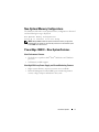 5
5
-
 6
6
-
 7
7
-
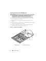 8
8
-
 9
9
-
 10
10
-
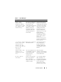 11
11
-
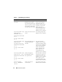 12
12
-
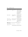 13
13
-
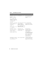 14
14
-
 15
15
-
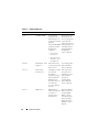 16
16
-
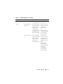 17
17
-
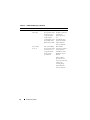 18
18
-
 19
19
-
 20
20
-
 21
21
-
 22
22
-
 23
23
-
 24
24
-
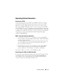 25
25
-
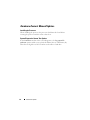 26
26
-
 27
27
-
 28
28
-
 29
29
-
 30
30
-
 31
31
-
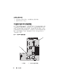 32
32
-
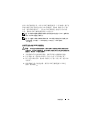 33
33
-
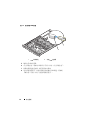 34
34
-
 35
35
-
 36
36
-
 37
37
-
 38
38
-
 39
39
-
 40
40
-
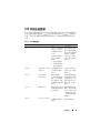 41
41
-
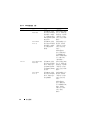 42
42
-
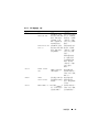 43
43
-
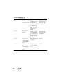 44
44
-
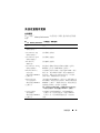 45
45
-
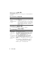 46
46
-
 47
47
-
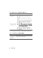 48
48
-
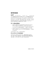 49
49
-
 50
50
-
 51
51
-
 52
52
-
 53
53
-
 54
54
-
 55
55
-
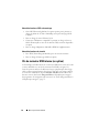 56
56
-
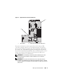 57
57
-
 58
58
-
 59
59
-
 60
60
-
 61
61
-
 62
62
-
 63
63
-
 64
64
-
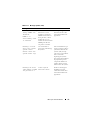 65
65
-
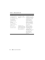 66
66
-
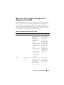 67
67
-
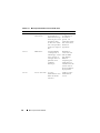 68
68
-
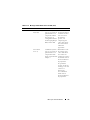 69
69
-
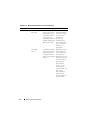 70
70
-
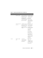 71
71
-
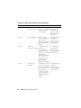 72
72
-
 73
73
-
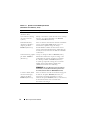 74
74
-
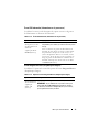 75
75
-
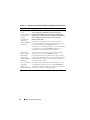 76
76
-
 77
77
-
 78
78
-
 79
79
-
 80
80
-
 81
81
-
 82
82
-
 83
83
-
 84
84
-
 85
85
-
 86
86
-
 87
87
-
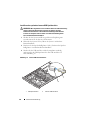 88
88
-
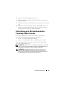 89
89
-
 90
90
-
 91
91
-
 92
92
-
 93
93
-
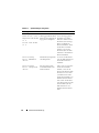 94
94
-
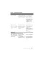 95
95
-
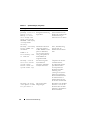 96
96
-
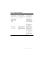 97
97
-
 98
98
-
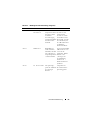 99
99
-
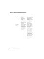 100
100
-
 101
101
-
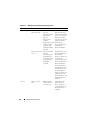 102
102
-
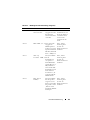 103
103
-
 104
104
-
 105
105
-
 106
106
-
 107
107
-
 108
108
-
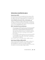 109
109
-
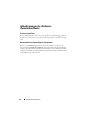 110
110
-
 111
111
-
 112
112
-
 113
113
-
 114
114
-
 115
115
-
 116
116
-
 117
117
-
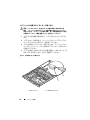 118
118
-
 119
119
-
 120
120
-
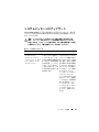 121
121
-
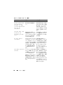 122
122
-
 123
123
-
 124
124
-
 125
125
-
 126
126
-
 127
127
-
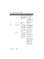 128
128
-
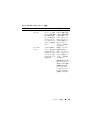 129
129
-
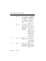 130
130
-
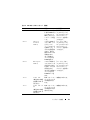 131
131
-
 132
132
-
 133
133
-
 134
134
-
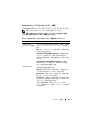 135
135
-
 136
136
-
 137
137
-
 138
138
-
 139
139
-
 140
140
-
 141
141
-
 142
142
-
 143
143
-
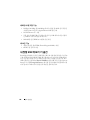 144
144
-
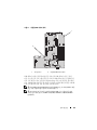 145
145
-
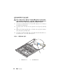 146
146
-
 147
147
-
 148
148
-
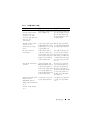 149
149
-
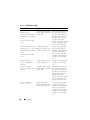 150
150
-
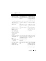 151
151
-
 152
152
-
 153
153
-
 154
154
-
 155
155
-
 156
156
-
 157
157
-
 158
158
-
 159
159
-
 160
160
-
 161
161
-
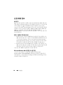 162
162
-
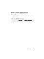 163
163
-
 164
164
-
 165
165
-
 166
166
-
 167
167
-
 168
168
-
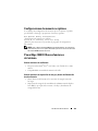 169
169
-
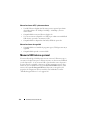 170
170
-
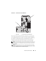 171
171
-
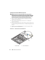 172
172
-
 173
173
-
 174
174
-
 175
175
-
 176
176
-
 177
177
-
 178
178
-
 179
179
-
 180
180
-
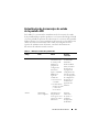 181
181
-
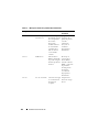 182
182
-
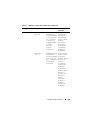 183
183
-
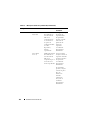 184
184
-
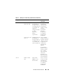 185
185
-
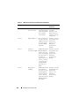 186
186
-
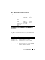 187
187
-
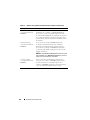 188
188
-
 189
189
-
 190
190
-
 191
191
-
 192
192
-
 193
193
-
 194
194


en otros idiomas
- français: Dell PowerEdge 1950 Mode d'emploi
- English: Dell PowerEdge 1950 User guide
- Deutsch: Dell PowerEdge 1950 Benutzerhandbuch
- 日本語: Dell PowerEdge 1950 ユーザーガイド
Artículos relacionados
-
Dell PowerEdge 2900 Guía del usuario
-
Dell PowerEdge R900 Guía del usuario
-
-
-
-
-
-
-
-