Iluminarc LOGIC Wall Panel Guia de referencia
- Categoría
- Focos
- Tipo
- Guia de referencia

English EN
Español ES
Français FR
Deutsch DE
Nederlands NL
Quick Reference Guide
Model ID: LOGICWALLPANEL16PORT
Scan the QR code to
access the product page,
warranty terms, and the
complete User Manual
Wall Panel 16-Port

1
EN
QUICK REFERENCE GUIDE
LΩGIC Wall Panel 16- Port QRG Rev. 2
Safety Notes
These Safety Notes include important information about installation, use, and maintenance of the LΩGIC Wall Panel 16-
Port.
FCC Statement of Compliance
This device complies with Part 15 Part B of the FCC rules. Operation is subject to the following two conditions:
1. This device may not cause harmful interference, and
2. This device must accept any interference received, including interference that may cause undesired operation.
This equipment has been tested and found to comply with the limits for a Class B digital device, pursuant to Part 15 of the
FCC Rules. These limits are designed to provide reasonable protection against harmful interference in a residential
installation. This equipment generates uses and can radiate radio frequency energy and, if not installed and used in
accordance with the instructions, may cause harmful interference to radio communications. However, there is no
guarantee that interference will not occur in a particular installation. If this equipment does cause harmful interference to
radio or television reception, which can be determined by turning the equipment off and on, the user is encouraged to try
to correct the interference by one or more of the following measures:
• Reorient or relocate the receiving antenna.
• Increase the separation between the equipment and receiver.
• Connect the equipment into an outlet on a circuit different from that to which the receiver is connected.
• Consult the dealer or an experienced radio/TV technician for help.
Any changes or modifications not expressly approved by the party responsible for compliance could void the user’s
authority to operate the equipment.
What is Included
AC Power
This product has an auto-ranging power supply that can work with an input voltage range of 200–240 VAC, 50/60 Hz.
AC Plug
• CAUTION:
• This product’s housing may be hot when operating. Mount this product in a location with adequate
ventilation, at least 20 in (50 cm) from adjacent surfaces.
• When transferring the product from extreme temperature environments, (e.g., cold truck to warm humid
ballroom) condensation may form on the internal electronics of the product. To avoid causing a failure,
allow the product to fully acclimate to the surrounding environment before connecting it to power.
• Only qualified and competent persons should open this product for servicing. Turn off power before
servicing!
• An external breaker and/or fuse branch-type overcurrent protection is required when running the product
under a municipal electric environment.
• ALWAYS:
• Use a safety cable when mounting this product overhead.
• Connect this product to a grounded and protected circuit.
•DO NOT:
• Leave any flammable material within 0.3 m of this product while operating or connected to power.
• Connect this product to a dimmer or rheostat.
• Operate this product if the housing or cables appear damaged.
• Operate this product outdoors or in any location where dust, excessive heat, water, or humidity may affect
it. (IP20)
• The maximum ambient temperature is 113 °F (45 °C). Do not operate this product at higher temperatures.
• The minimum ambient temperature is -4°F (-20°C). Do not operate the product at lower temperatures.
• To eliminate unnecessary wear and improve its lifespan, during periods of non-use completely disconnect the
product from power via breaker or by unplugging it.
• In the event of a serious operating problem, stop using immediately.
•LΩGIC Wall Panel 16- Port
• Door keys (X2)
• Quick Reference Guide
Connection Wire (U.S.) Wire (Europe) Screw Color
AC Live Black Brown Yellow/Brass
AC Neutral White Blue Silver
AC Ground Green/Yellow Green/Yellow Green

EN
2
LΩGIC Wall Panel 16- Port QRG Rev. 2
QUICK REFERENCE GUIDE
Product Overview
Front Overview
#Name Function
1 LED indicators
POWER: green, indicates power connection
ETHERNET: yellow, indicates ethernet connection
ACTIVITY (control): white, indicates controller signal
ERROR/ALERT: disconnected fixtures cause this LED to light, among other alerts. Red,
indicates an error (see Warning Messages in the menu)
2
MENU/ENTER
Rotate to navigate upwards or downwards through the menu list, and increase or decrease a
selected numeric value. Push to enable the currently displayed menu option or set the currently
selected value into the selected function.
3 <BACK> button Exits the current menu or function
4LOGIC FIXTURE
OUTPUTS IEEE 802.3bt POE RJ45 connector for output LΩGIC products
5
WALL CON
OUTPUT 1/2
RJ12 connectors for LΩGIC Wall Controller
6 DMX IN 5-pin phoenix connector for DMX input
7 DMX THRU 5-pin phoenix connector for DMX output
8NETWORK IN/
THRU RJ45 connectors for Ethernet input and through
Door
handle
LCD Display
Breakers
Door closed Door open
3
2
Lock
1
4
5678
Rack/ mounting ears

3
EN
QUICK REFERENCE GUIDE
LΩGIC Wall Panel 16- Port QRG Rev. 2
Side Overview
2 in
51 mm
1.75 in
44 mm
1.5 in
38 mm
1.25 in
32 mm
knockout dimensions
1 in
25 mm

EN
4
LΩGIC Wall Panel 16- Port QRG Rev. 2
QUICK REFERENCE GUIDE
LΩGIC Wall Controller
Each LΩGIC Wall Panel 16- Port comes with a wall-mounted control panel (LΩGIC Wall Controller) which can plug into
the RJ12 connector on the back of the product. Download the User Manual from www.iluminarc.com for more
information.
• Buttons 1–8 trigger playback of the corresponding recorded programs.
• Buttons 9 and 10 decrease and increase the brightness of the connected LOGIC products.
• 5-bit DIP switches set the address of the LΩGIC Wall Controller.
DMX Linking
The LΩGIC Wall Panel 16- Port will work with a DMX controller using a 5-pin phoenix connector. A DMX Primer is
available from www.iluminarc.com.
DMX Connection
The LΩGIC Wall Panel 16- Port provides a DMX 512 connection using a 5-pin phoenix connector. See the User Manual
for information about connecting and configuring the product for DMX operation.
1–8
910
RJ12 with flipped/ reverse wiring
DIP switches use binary addressing
DIP switches
5=1
4=2
3=4
2=8
1=16
Example:
5-1 (ON)
4-0
3-1 (ON) = 00101 = 5
2-0
1-0
1. Ground
2. Data 1 -
3. Data 1 +
4. Not used
5. Not used
DMX Output Signal Connector

5
EN
QUICK REFERENCE GUIDE
LΩGIC Wall Panel 16- Port QRG Rev. 2
Remote Device Management
Remote Device Management, or RDM, is a standard for allowing DMX-enabled devices to communicate bi-directionally
along existing DMX cabling. Check the DMX controller’s User Manual or with the manufacturer as not all DMX controllers
have this capability. The LΩGIC Wall Panel 16- Port supports RDM protocol that allows feedback to make changes to
menu map options. Download the User Manual from www.iluminarc.com for more details and an RDM chart.
Signal Connection
The LΩGIC Wall Panel 16- Port can link to controller software using an Ethernet connection. If using other Art-Net™ or
sACN -compatible products with the LΩGIC Wall Panel 16- Port, you can control each individually on a single network.
See the User Manual for information about how to connect and configure the product for these signals.
Art-Net™ Connection
Art-Net™ is an Ethernet protocol that uses TCP/IP which transfers a large amount of DMX512 data using an RJ45
connection over a large network. An Art-Net™ protocol document is available from www.iluminarc.com.
Art-Net™ designed by and copyright Artistic Licence Holdings Ltd.
sACN Connection
Also known as ANSI E1.31, Streaming-ACN is an Ethernet protocol that uses the layering and formatting of Architecture
for Control Networks to transport DMX512 data over IP or any other ACN compatible network.
Mounting
Before mounting this product, read the Safety Notes. The LΩGIC Wall Panel 16- Port:
• Can be mounted using a wall mount.
• can be mounted using a rack mount.
Make sure the mounting hardware is capable of supporting the weight of the product.
Mounting Diagram
It is possible to detach the rack ears and move them to the front of the product for rack mount
installation.
M8 bolts,
or
1/4 In bolts/screws,
or
3/8 in bolt/screws

EN
6
LΩGIC Wall Panel 16- Port QRG Rev. 2
QUICK REFERENCE GUIDE
Menu Map
Refer to the LΩGIC Wall Panel 16- Port product page on www.iluminarc.com for the latest menu map.
Main Level Programming Levels Description
Protocol
DMX512
Selects the control protocolArtNet
sACN
Local
Output
Status Output 1-32
Status
Status: _ _ _ _ _ Shows Normal or Fault
Connect: _ _ _ Shows On or Off
CLASS: _ _ _ _ Shows None or 1–8
V1: _._ V Cur 1: _._ mA Shows voltage and current of output
V2: _._ V Cur 2: _._ mA
Power: _._ W Shows power of output
Net Switch 2.X.X.X Selects the first value of the IP
address
10.X.X.X
Universe 000–255 / 001–256
Selects universe
(Art-Net™) (sACN)
Password ON Enables/disables password lock:
123456
OFF
Priority Control panel Wall Con input has priority
Signal Signal input has priority
History
List _ _ _ _ _ Displays connected product history
Clear No Cancel clear
Yes Clear history
Wall Con
Zone
Wall Con
Zone One Group 1-16 Wall Con
1-4
0–31
Sets zone and group of selected Wall
Con, or disables it
OFF
Wall Con
Zone Two Group 1-16 Wall Con
1-4
0–31
OFF
Local Info
Version V _._ _ Shows current firmware version
IP Address _ _ _._ _ _._ _ _._ _ _ Shows the IP address
Fixture
Hours
_ hours Shows length of time product has
been on
_ _minutes
_ _ seconds
Label LOGIC Wall Panel Shows device label
Device UID _ _ _ _ _ _-_ _ _ _ _ _ _ _ Shows device UID
MAC Address
_ _ _ _ _ _ _ _ _ _ _ _ _ _ Shows the MAC address
Temperature _ _._ °C Shows the current temperature in °C
Power 1
Temperature _ _._ °C Shows NTC 1 temperature in °C
Power 2
Temperature _ _._ °C Shows NTC 2 temperature in °C
Power 3
Temperature _ _._ °C Shows NTC 3 temperature in °C
Power 4
Temperature _ _._ °C Shows NTC 4 temperature in °C

7
EN
QUICK REFERENCE GUIDE
LΩGIC Wall Panel 16- Port QRG Rev. 2
Local
(cont.)
Local Info
(cont.) Warning
Messages
0. 1=DMX signal lost; 2=Network
disconnect; 3= Artnet signal lost;
4= Sacn signal lost;
1. Output 1 Overcurrent
2. Output 2 Overcurrent
3. Output 1-Short Circuit
4. Output 2-Short Circuit
5. POE Device No longer connected
(may have failed)
6. POE Device Error-undefined
7. POE Hardware Error-undefined
8. Internal network hardware error
9. DRIVER 2X Overheat
10. POE Device overheat (detail
which device when selected)
Shows current error(s), e.g. “DMX
Signal Lost” or “Devices No Longer
Detected”
System
Reset
No Resets the LΩGIC Wall Panel 16-
Port to factory default settings
Yes
Match Net No Sets fixture segment to driver
segment
Yes
Linked
Fixture
Order 1- _ Displays order of connected fixtures
Output 1-32 Displays fixture port
Model _ _ _ _ _ Displays fixture name
Personality
RED 1-channel: dimmer (red only)
GREEN 1-channel: dimmer (green only)
BLUE 1-channel: dimmer (blue only)
WHITE 1-channel: dimmer
TW 2-channel, Tunable White: dimmer,
color temperature
RGB 3-channel: RGB
RGBW 4-channel: RGBW
RGBW+D 5-channel: dimmer, RGBW
FULL 10-channel: dimmer, RGBW, color
macros, strobe, auto programs and
speed, dimmer speed
DMX
Address 001–512 Sets DMX address
Universe 0–255 Sets universe
Version v_._ _ Displays current version
Discover _ _ _ Search for device
Fixture
Network Net Switch
2. _ . _ . _
Sets the IP address
10 . _ . _ . _
IP Address 2 . _ . _ . _ Shows the linked device IP address
Device UID _ _ _ _ _ _ _ _ _ _ _ _ _ _ Shows the linked device UID
MAC
Address 0 _ _ _ _ _ _ _ _ _ _ _ _ _ _ Shows the linked device MAC
address
Temperature _ . _°C Displays linked device temperature
Label _ _ _ Displays linked device name
Fixture
Hours _ _ _ hours Displays working hours of linked
device
Factory
Reset
No Resets linked device
Yes
Main Level Programming Levels Description

EN
8
LΩGIC Wall Panel 16- Port QRG Rev. 2
QUICK REFERENCE GUIDE
Static
Red 000–255 Temporary manual control of all
connected products. Combine red,
green, blue, and white to make a
custom color.
Green 000–255
Blue 000–255
White 000–255
Strobe 000–255 Sets standalone strobe speed
Record
Play Record1–64
_ _: _ _: _ _ Record 1–64: Play/
pause
Plays back recorded input. Press the
<Encoder> knob to toggle play and
stop.
Record Record1–64 Record 1–64 Clr Captures/records live controller input
to selected Record slot. Press the
<Encoder> knob to start and stop.
System
Clock
Schedule
Everyday Turn on Turn off Schedules daily times to turn on and
off (stackable with other schedule
options)
00–23:00–59:00–59
By date
Turn on Turn off
Schedules a date and time to turn on
and off (stackable with other schedule
options)
Month:01–12 Month:01–
12
Day:01–31 Day:01–31
Year:2000–99 Year:2000–
99
By week
Mon :
Schedules which days of the week to
be on or off (stackable with other
schedule options)
Tues :
Wed :
Thur :
Fri :
Sat :
Sun :
Setting
Clock
SysClock: 24 hours Shows system clock is 24-hour
Date: 01–12:01–31:2000–2099 Sets the current date
Time: 00–23:00–59:00–59 Sets the current time
Week: 1–7 Sets the current day of the week
Fade In/Out
Fade In On-instant Sets fade in to instant
On-3second fade Sets fade in to 3-second fade
Fade Out Off-instant Sets fade out to instant
Off-3second fade Sets fade out to 3-second fade
Enable
Clock
No Enables/disables clock functions
Yes
Main Level Programming Levels Description

9
EN
QUICK REFERENCE GUIDE
LΩGIC Wall Panel 16- Port QRG Rev. 2
RDM Chart
Refer to the LΩGIC Wall Panel 16- Port product page on www.iluminarc.com for the latest RDM Chart.
GET SET
Category RDM Parameter IDs (Slot 21-22) Value
Required
Detail
Network
Management
DISC_UNIQUE_BRANCH 0x0001
DISC_MUTE 0x0002
DISC_UN_MUTE 0x0003
RDM
Information
QUEUED_MESSAGE 0x0020
SUPPORTED_PARAMETERS 0x0050
IDENTIFY_DEVICE, DEVICE_INFO,
SOFTWARE_VERSION_LABEL,
SUPPORTED_PARAMETERS,
DMX_START_ADDRESS,
DEVICE_MODEL_DESCRIPTION,
MANUFACTURER_LABEL,
DEVICE_LABEL, DMX_PERSONALITY,
PERSONALITY_DESCRIPTION,
SENSOR_DEFINITION, SENSOR_VALUE
PARAMETER_DESCRIPTION 0x0051
Product
Information
DEVICE_INFO 0x0060
1, RDM Protocol Version: V1.0;
2, Device_Mode_ID: 0x21A408B9;
3, Product Category Defines:
PRODUCT_CATEGORY_FIXTURE_FIXED;
4, Software Version ID;
5, DMX512 Footprint;
6, DMX512 Personality;
7, DMX512 Start Address;
8, Sensor Count;
PRODUCT_DETAIL_ID_LIST 0x0070
DEVICE_MODEL_DESCRIPTION 0x0080 LOGIC WALL PANEL
MANUFACTURER_LABEL 0x0081 ILUMINARC
DEVICE_LABEL 0x0082 LOGIC WALL PANEL
SOFTWARE_VERSION_LABEL 0x00C0 V_._
FACTORY_DEFAULTS FACTORY_DEFAULTS : yes
DMX Setup
DMX_PERSONALITY 0x00E0 9pcs persons
DMX_PERSONALITY_DESCRIPTION
0x00E1 RED/1CH, GREEN/1CH, BLUE/1CH,
WHITE/1CH, TW/2CH, RGB/3CH, RGBW/
4CH, RGBW+D/5CH, FULL/10CH
DMX_START_ADDRESS 0x00F0 1-503
Sensors SENSOR_DEFINITION 0x0200 0.) Product Temperature _ _ °C
SENSOR_VALUE 0x0201 —20° —100°
Control IDENTIFY_DEVICE 0x1000 Identify State: Off

ES
10
LOGIC Wall Panel 16- Port GRR Rev. 2
GUÍA DE REFERENCIA RÁPIDA
Notas de seguridad
Estas notas de seguridad incluyen información importante sobre la instalación, el uso y el mantenimiento del
LOGIC Wall Panel 16- Port.
Declaración de conformidad de la FCC
Este dispositivo cumple con la Parte 15 Parte B de las normas de la FCC. El funcionamiento está sujeto a las dos
condiciones siguientes:
1. Este dispositivo no puede causar interferencias perjudiciales, y
2. Este dispositivo debe aceptar cualquier interferencia recibida, incluyendo las que puedan causar un
funcionamiento no deseado.
Este equipo ha sido probado y cumple los límites establecidos para los dispositivos digitales de Clase B, de conformidad
con la Parte 15 de las normas de la FCC. Estos límites están diseñados para proporcionar una protección razonable
contra las interferencias perjudiciales en una instalación residencial. Este equipo genera, utiliza y puede irradiar energía
de radiofrecuencia y, si no se instala y utiliza de acuerdo con las instrucciones, puede causar interferencias perjudiciales
en las comunicaciones por radio. Sin embargo, no hay garantía de que no se produzcan interferencias en una instalación
concreta. Si este equipo causa interferencias perjudiciales en la recepción de radio o televisión, lo cual puede
determinarse apagando y encendiendo el equipo, se recomienda al usuario que intente corregir las interferencias
mediante una o varias de las siguientes medidas:
• Reorientar o reubicar la antena receptora.
• Aumentar la separación entre el equipo y el receptor.
• Conectar el equipo a una toma de corriente de un circuito distinto al que está conectado el receptor.
• Consulte al distribuidor o a un técnico experto en radio/TV para obtener ayuda.
Cualquier cambio o modificación que no esté expresamente aprobado por la parte responsable del cumplimiento podría
anular la autoridad del usuario para operar el equipo.
Qué se incluye
Corriente Alterna
Este producto tiene una fuente de alimentación con detección automática que.uede funcionar con un rango de tensión
de entrada de 200 a 240 VCA, 50/60 Hz.
• PRECAUCIÓN:
• Solo personal calificado y competente debe abrir este producto para su mantenimiento.
¡Desconecte la
alimentación antes de realizar el mantenimiento!
•
La carcasa de este producto puede estar caliente durante su funcionamiento. Monte este producto en un lugar
con una ventilación adecuada, a una distancia mínima de 50 cm (20 pulg.) de las superficies adyacentes.
• Cuando se transfiere el producto desde entornos con temperaturas extremas (por ejemplo, de un camión
refrigerado a un salón de baile cálido y húmedo), puede formarse condensación en los componentes
electrónicos internos del producto. Para evitar que se produzca una falla, deje que el producto se aclimate
completamente al entorno antes de conectarlo a la corriente.
•Se requiere una protección contra sobrecorriente de tipo ramal mediante disyuntor externo y/o fusible
cuando el producto funciona en un entorno eléctrico municipal.
•SIEMPRE:
• Utilice un cable de seguridad cuando monte este producto por encima de la cabeza.
• Conecte este producto a un circuito con toma de tierra y protegido.
• NO HACER:
• Dejar cualquier material inflamable a menos de 0.3 m de este producto mientras esté en funcionamiento
o conectado a la corriente.
• Conectar este producto a un regulador o reostato.
• Utilizar este producto si la carcasa o los cables parecen estar dañados.
• Utilizar este producto al aire libre o en cualquier lugar donde el polvo, el calor excesivo, el agua o la
humedad puedan afectarlo. (IP20)
• La temperatura ambiente máxima es de 45 °C (113 °F). No utilice este producto a temperaturas más altas.
• La temperatura de ambiente mínima es de -20 °C (-4 °F). No utilice este producto a temperaturas más bajas.
• Para eliminar el desgaste innecesario y mejorar su vida útil, durante los periodos en que no lo utilice,
desconecte completamente el producto de la corriente mediante un disyuntor o desenchufándolo.
• En caso de un problema grave de funcionamiento, deje de usarlo inmediatamente.
• LOGIC Wall Panel 16- Port
• Llaves de puetra (X2)
• Guía de Referencia Rápida

11
ES
GUÍA DE REFERENCIA RÁPIDA
LOGIC Wall Panel 16- Port GRR Rev. 2
Enchufe CA
Vista general del producto
Vista frontal
Conexión Cable (EE.UU.) Cable (Europa) Color del tornillo
CA Cargado Negro Marrón Amarillo/Latón
CA Neutro Blanco Azul Plata
CA Tierra Verde/Amarillo Verde/Amarillo Verde
#Nombre Función
1 LED indicators
POWER: verde, indica conexión de alimentación
NET: amarillo, indica conexión Ethernet
ACT: blanco, indica señal del controlador
ERROR/ALERT: Los dispositivos desconectados hacen que se encienda este LED, entre otras
alertas.rojo, indica un error (ver Warning Messages en el menú)
2
MENU/ENTER
Gire para desplazarse hacia adelante o hacia atrás por la lista de menú, y aumente o disminuya
un valor numérico seleccionado. Pulse para habilitar la opción de menú actualmente visualizada
o configurar el valor seleccionado actualmente dentro de la función seleccionada.
3 <BACK> button Sale del menú o función actual
4LOGIC FIXTURE
OUTPUTS Conector RJ45 POE IEEE 802.3bt para productos LΩGIC de salida.
5
WALL CON
OUTPUT 1/2
Conector RJ12 para LΩGIC Wall Controller
Tirador
de
puerta
LCD Display
Disyuntores
Puerta cerrada Puerta abierta
3
2
Cerradura
1
4
5678
Bastidor/ orejetas de montaje

ES
12
LOGIC Wall Panel 16- Port GRR Rev. 2
GUÍA DE REFERENCIA RÁPIDA
6 DMX IN Conector Phoenix de 5 pines para entrada DMX
7 DMX THRU Conector Phoenix de 5 pines para salida DMX
8NETWORK IN/
THRU Conectores RJ45 para entrada y paso de Ethernet
#Nombre Función

13
ES
GUÍA DE REFERENCIA RÁPIDA
LOGIC Wall Panel 16- Port GRR Rev. 2
Descripción general lateral
2’’
51 mm
1.75‘’
44 mm
1.5’’
38 mm
1.25’’
32 mm
Dimensiones de perforación
1’’
25 mm

ES
14
LOGIC Wall Panel 16- Port GRR Rev. 2
GUÍA DE REFERENCIA RÁPIDA
LΩGIC Wall Controller
Cada LOGIC Wall Panel 16- Port viene con un panel de control de montaje mural (LΩGIC Wall Controller) que se
conecta a un conector RJ12 en la parte posterior del producto.
• Los botones 1-8 activan la reproducción de los correspondientes programas grabados.
• Los botones 9 y 10 aumentan o disminuyen el brillo de los productos LΩGIC conectados.
Conmutadores DIP de 5 bits configuran la dirección del LΩGIC Wall Controller
Enlace DMX
El LOGIC Wall Panel 16- Port funcionará con un controlador DMX usando una conector phoenix de 5 pines. Hay un
Manual DMX disponible en www.iluminarc.com.
Conexión DMX
El LOGIC Wall Panel 16- Port dispone de conexión DMX 512 mediante un conector Phoenix de 5 pines. Vea el Manual
de usuario para conectar y configurar para funcionamiento DMX.
1–8
910
RJ12 con cableado cruzado
Interruptores DIP utilizan
direccionamiento binario
Interruptores
DIP 5=1
4=2
3=4
2=8
1=16
Ejemplo:
5-1 (ON)
4-0
3-1 (ON) = 00101 = 5
2-0
1-0
1. Tierra
2. Datos -
3. Datos +
4. Sin uso
5. Sin uso
Salida DMX Conector de señal

15
ES
GUÍA DE REFERENCIA RÁPIDA
LOGIC Wall Panel 16- Port GRR Rev. 2
gestión remota del dispositivo
Remote Device Management (gestión remota del dispositivo) o RDM, es un estándar que permite a los dispositivos con
capacidad DMX una comunicación bidireccional por un cableado DMX existente. El LOGIC Wall Panel 16- Port admite
protocolo RDM, que posibilita información para supervisar cambiar las opciones del mapa de menú. Descargue el
manual de usuario de www.iluminarc.com para una información más detallada y un gráfico de RDM.
Conexiones de señal
Puede enlazar el LOGIC Wall Panel 16- Port a un controlador o software controlador usando una conexión Ethernet. Si está
usando otros
productos compatibles con Art-Net™ o sACN con el LOGIC Wall Panel 16- Port, puede controlar cada uno
individualmente en una sola
red. Consulte el Manual de usuario para obtener información sobre cómo conectar y configurar el
producto para estas señales.
Conexión Art-Net™
Art-Net™ es un protocolo Ethernet que utiliza TCP/IP para transferir gran cantidad de datos DMX512 usando una conexión
ethernet sobre una red de gran tamaño. Hay disponible un documento sobre el protocolo Art-Net™ desde www.iluminarc.com.
Art-Net™ diseñado y copyright por Artistic Licence Holdings Ltd.
Conexión sACN
También conocido como ANSI E1.31, el streaming ACN es un protocolo Ethernet que usa las capas y formato de
Architecture for Control Networks (arquitectura para redes de control) para transportar datos DMX512 sobre IP o
cualquier otra red compatible con ACN.
Montaje
Antes de montar este producto, lea las Notas de seguridad. El
LOGIC Wall Panel 16- Port:
• Se puede montar con un soporte de pared.
• Se puede montar con un soporte de bastidor.
Asegúrese de que los hardware de montaje son capaces de soportar el peso del producto.
Diagrama de Montaje
Es posible desmontar las orejetas de bastidor y moverlas a la parte frontal del producto para su
instalación en bastidor.
Pernos M8, o
pernos/tornillos
de ¼ pulg., o
tornillos de 3/8
pulg.

ES
16
LOGIC Wall Panel 16- Port GRR Rev. 2
GUÍA DE REFERENCIA RÁPIDA
Menu Map
Refer to the LOGIC Wall Panel 16- Port product page on www.iluminarc.com for the latest menu map.
Nivel
Principal
Niveles de Programación Descripción
Protocol
DMX512
Selecciona el protocolo de controlArtNet
sACN
Local
Output
Status Output 1-32
Status
Status: _ _ _ _ _ Muestra Normal o Fault
Connect: _ _ _ Muestra On o Off
CLASS: _ _ _ _ Muestra None o 1–8
V1: _._ V Cur 1: _._ mA Muestra la tensión y corriente de
salida
V2: _._ V Cur 2: _._ mA
Power: _._ W Muestra la potencia de salida
Net Switch 2.X.X.X Selecciona el primer valor de la
dirección IP
10.X.X.X
Universe 000–255 / 001–256 Selecciona el universo
(Art-Net™) (sACN)
Password ON Habilita/deshabilita el bloqueo de
contraseña: 123456
OFF
Priority Control panel El entrada da Wall Con tiene prioridad
Signal La entrada de señal tiene prioridad
History
List _ _ _ _ _
Muestra el historial de productos
conectados
Clear No Cancelar borrado
Yes Borrar historial
Wall Con
Zone
Wall Con
Zone One Group 1-16 Wall Con
1-4
0–31
Establece la zona de Wall Con
seleccionada o la desactiva
OFF
Wall Con
Zone Two Group 1-16 Wall Con
1-4
0–31
OFF
Local Info
Version V _._ _ Muestra instalada la versión de
firmware
IP Address _ _ _._ _ _._ _ _._ _ _ Muestra la dirección IP
Fixture
Hours
_ hours Muestra el nombre total de las horas
del producto
_ _minutes
_ _ seconds
Label LOGIC Wall Panel Muestra la etiqueta del producto
Device UID _ _ _ _ _ _-_ _ _ _ _ _ _ _ Muestra la UID del producto
MAC Address
_ _ _ _ _ _ _ _ _ _ _ _ _ _ Muestra la dirección MAC
Temperature _ _._ °C Muestra la temperatura actual en °C
Power 1
Temperature _ _._ °C Muestra la temperatura de NTC 1 en
°C
Power 2
Temperature _ _._ °C Muestra la temperatura de NTC 2 en
°C
Power 3
Temperature _ _._ °C Muestra la temperatura de NTC 3 en
°C
Power 4
Temperature _ _._ °C Muestra la temperatura de NTC 4 en
°C

17
ES
GUÍA DE REFERENCIA RÁPIDA
LOGIC Wall Panel 16- Port GRR Rev. 2
Local
(cont.)
Local Info
(cont.) Warning
Messages
0. 1=DMX signal lost; 2=Network
disconnect; 3= Artnet signal lost;
4= Sacn signal lost;
1. Output 1 Overcurrent
2. Output 2 Overcurrent
3. Output 1-Short Circuit
4. Output 2-Short Circuit
5. POE Device No longer connected
(may have failed)
6. POE Device Error-undefined
7. POE Hardware Error-undefined
8. Internal network hardware error
9. DRIVER 2X Overheat
10. POE Device overheat (detail
which device when selected)
Muestra los errores actuales, p. ej.,
“DMX
Signal Lost” o “Devices No
Longer Detected”
System
Reset
No Restablece el LOGIC Wall Panel 16-
Port a la configuración
predeterminada de fábric
Yes
Match Net No Establece el segmento de dispositivo
como segmento de controlador
Yes
Linked
Fixture
Order 1- _ Muestra el orden de los dispositivos
conectados
Output 1-32 Muestra el puerto del dispositivo
Model _ _ _ _ _ Muestra el nombre del dispositivo
Personality
RED 1 canal: atenuador (solamente rojo)
GREEN 1 canal: atenuador (solamente verde)
BLUE 1 canal: atenuador (solamente azul)
WHITE 1 canal: atenuador
TW 2 canales, Blanca Ajustable:
atenuador, temperatura de color
RGB 3 canales: control RGB
RGBW 4 canales: control RGBW
RGBW+D 5 canales: atenuador, control RGBW
FULL
10 canales: atenuador, RGBW,
macros de
color, estroboscopio,
programas automáticos
y velocidad,
velocidad de atenuador
DMX
Address 001–512 Establece la dirección DMX
Universe 0–255 Establece el universo
Version v_._ _ Muestra la versión actual
Discover _ _ _ Búsqueda de dispositivo
Nivel
Principal
Niveles de Programación Descripción

ES
18
LOGIC Wall Panel 16- Port GRR Rev. 2
GUÍA DE REFERENCIA RÁPIDA
Linked
Fixture
(cont.) Fixture
Network Net Switch
2. _ . _ . _
Establece la dirección IP
10 . _ . _ . _
IP Address 2 . _ . _ . _ Muestra la dirección IP del dispositivo
vinculado
Device UID _ _ _ _ _ _ _ _ _ _ _ _ _ _ Muestra la UID del dispositivo
vinculado
MAC
Address 0 _ _ _ _ _ _ _ _ _ _ _ _ _ _ Muestra la dirección MAC del
dispositivo vinculado
Temperature _ . _°C Muestra la temperatura del dispositivo
vinculado
Label _ _ _ Muestra el nombre del dispositivo
vinculado
Fixture
Hours _ _ _ hours Muestra las horas de funcionamiento
del dispositivo vinculado
Factory
Reset
No Restablece el dispositivo vinculado
Yes
Static
Red 000–255 Control manual temporal de todos los
productos conectados. Combina rojo,
verde, azul y blanco para generar un
color personalizado
Green 000–255
Blue 000–255
White 000–255
Strobe 000–255 Establece la frecuencia del
estroboscopio
Record
Play Record1–64
_ _: _ _: _ _ Record 1–64: Play/
pause
Reproduce la entrada grabada. Pulse
<MENU>
para cambiar entre
reproducción y pausa.
Record Record1–64 Record 1–64 Clr
Captura/graba la entrada de
controlador en vivo a la ranura de
Grabación seleccionada Pulse
<MENU> para iniciar y detener.
Nivel
Principal
Niveles de Programación Descripción

19
ES
GUÍA DE REFERENCIA RÁPIDA
LOGIC Wall Panel 16- Port GRR Rev. 2
System
Clock
Schedule
Everyday Turn on Turn off Programa las horas diarias para
encender y apagar (acumulable con
otras opciones)
00–23:00–59:00–59
By date
Turn on Turn off
Programa una fecha y hora para
encender y apagar (acumulable con
otras opciones de programación)
Month:01–12 Month:01–
12
Day:01–31 Day:01–31
Year:2000–99 Year:2000–
99
By week
Mon :
Programa qué días de la semana
estará encendido o apagado
(acumulable con otras opciones de
programación)
Tues :
Wed :
Thur :
Fri :
Sat :
Sun :
Setting
Clock
SysClock: 24 hours
Muestra que el reloj del sistema es de 24
horas
Date: 01–12:01–31:2000–2099 Establece la fecha actual
Time: 00–23:00–59:00–59 Establece la hora actual
Week: 1–7 Establece el día actual de la semana
Fade In/Out
Fade In
On-instant Configura el fade in en instantáneo
On-3second fade Configura el fade in en un fade de 3
segundos
Fade Out
Off-instant Configura el fade out en instantáneo
Off-3second fade Configura el fade out en un fade de 3
segundos
Enable
Clock
No Habilita/deshabilita las funciones del
reloj
Yes
Nivel
Principal
Niveles de Programación Descripción

ES
20
LOGIC Wall Panel 16- Port GRR Rev. 2
GUÍA DE REFERENCIA RÁPIDA
Gráfico RDM
Consulte la página del producto LOGIC Wall Panel 16- Port en www.iluminarc.com para ver el último gráfico RDM.
GET SET
Category RDM Parameter IDs (Slot 21-22) Value
Required
Detail
Network
Management
DISC_UNIQUE_BRANCH 0x0001
DISC_MUTE 0x0002
DISC_UN_MUTE 0x0003
RDM
Information
QUEUED_MESSAGE 0x0020
SUPPORTED_PARAMETERS 0x0050
IDENTIFY_DEVICE, DEVICE_INFO,
SOFTWARE_VERSION_LABEL,
SUPPORTED_PARAMETERS,
DMX_START_ADDRESS,
DEVICE_MODEL_DESCRIPTION,
MANUFACTURER_LABEL,
DEVICE_LABEL, DMX_PERSONALITY,
PERSONALITY_DESCRIPTION,
SENSOR_DEFINITION, SENSOR_VALUE
PARAMETER_DESCRIPTION 0x0051
Product
Information
DEVICE_INFO 0x0060
1, RDM Protocol Version: V1.0;
2, Device_Mode_ID: 0x21A408B9;
3, Product Category Defines:
PRODUCT_CATEGORY_FIXTURE_FIXED;
4, Software Version ID;
5, DMX512 Footprint;
6, DMX512 Personality;
7, DMX512 Start Address;
8, Sensor Count;
PRODUCT_DETAIL_ID_LIST 0x0070
DEVICE_MODEL_DESCRIPTION 0x0080 LOGIC WALL PANEL
MANUFACTURER_LABEL 0x0081 ILUMINARC
DEVICE_LABEL 0x0082 LOGIC WALL PANEL
SOFTWARE_VERSION_LABEL 0x00C0 V_._
FACTORY_DEFAULTS FACTORY_DEFAULTS : yes
DMX Setup
DMX_PERSONALITY 0x00E0 9pcs persons
DMX_PERSONALITY_DESCRIPTION
0x00E1 RED/1CH, GREEN/1CH, BLUE/1CH,
WHITE/1CH, TW/2CH, RGB/3CH, RGBW/
4CH, RGBW+D/5CH, FULL/10CH
DMX_START_ADDRESS 0x00F0 1-503
Sensors SENSOR_DEFINITION 0x0200 0.) Product Temperature _ _ °C
SENSOR_VALUE 0x0201 —20° —100°
Control IDENTIFY_DEVICE 0x1000 Identify State: Off

21
FR
GUIDE DE RÉFÉRENCE RAPIDE
LOGIC Wall Panel 16- Port GRR Rev. 2
Consignes de sécurité
Ces consignes de sécurité contiennent des informations importantes sur l’installation, l’utilisation et l’entretien de
LOGIC Wall Panel 16- Port.
Déclaration de conformité à la FCC
Cet appareil est conforme à la partie 15, partie B des règles de la FCC. Le fonctionnement est soumis aux deux conditions suivantes
:
1. Cet appareil ne doit pas causer d’interférences nuisibles et
2. Cet appareil doit accepter toute interférence reçue, y compris les interférences susceptibles de provoquer un
fonctionnement indésirable.
Cet équipement a été testé et déclaré conforme aux limites d’un appareil numérique de classe B, conformément à la
partie 15 des règles de la FCC. Ces limites sont établies pour fournir une protection raisonnable contre les interférences
nuisibles dans une installation résidentielle. Cet équipement génère des utilisations et peut émettre de l’énergie de
radiofréquence et, s’il n’est pas installé et utilisé conformément aux instructions, il peut causer des interférences nuisibles
aux communications radio. Cependant, il n’y a aucune garantie que des interférences ne se produiront pas dans une
installation particulière. Si cet équipement cause des interférences nuisibles à la réception radio ou télévision, ce qui peut
être déterminé en éteignant et en rallumant l’équipement, l’utilisateur est encouragé à essayer de corriger l’interférence
par une ou plusieurs des mesures suivantes :
• Réorienter ou déplacer l’antenne de réception.
• Augmenter la distance entre l’équipement et le récepteur.
• Brancher l’équipement à une prise sur un circuit différent de celui auquel le récepteur est connecté.
• Consulter le revendeur ou un technicien radio/TV expérimenté afin d’obtenir de l’aide.
Tout changement ou modification non expressément approuvé(e) par la partie responsable de la conformité pourrait
annuler l’autorité de l’utilisateur à faire fonctionner l’équipement.
Contenu de la boîte
Alimentation CA
Cet appareil est doté d'une alimentation universelle prenant charge toute tension d'entrée comprise entre 200 et 240 VCA, 50/60 Hz.
• ATTENTION :
• Seules des personnes qualifiées et compétentes doivent ouvrir ce produit pour maintenance. Coupez le
courant avant toute maintenance!
• Le boîtier de ce produit peut être chaud lorsqu’il fonctionne. Montez ce produit dans un endroit avec une
ventilation adéquate, à au moins 20 po (50 cm) des surfaces adjacentes.
• Lors du transfert d’un produit à partir d’environnements à température extrême (par exemple, un camion
froid vers une salle de réception chaude et humide), de la condensation peut se former sur les composants
électroniques internes du produit. Pour éviter de provoquer une panne, laissez le produit s’acclimater
complètement au milieu environnant avant de le brancher.
•Une protection contre les surintensités de type disjoncteur externe et/ou fusible est requise lors du
fonctionnement du produit dans un environnement électrique municipal.
• TOUJOURS :
• Utiliser un câble de sécurité lors du montage de ce produit en hauteur.
• Brancher ce produit à un circuit relié à la terre et protégé.
•NE PAS:
• Laisser de matériau inflammable à moins de 0.3 m de ce produit lorsqu’il fonctionne ou s’il est branché.
• Brancher ce produit à un variateur ou à un rhéostat.
• Utiliser ce produit si le boîtier ou les câbles semblent endommagés.
• Utiliser ce produit à l’extérieur ou dans un endroit où la poussière, la chaleur excessive, l’eau ou l’humidité
peuvent l’affecter. (IP20)
• La température ambiante maximale est de 113 °F (45 °C). Ne faites pas fonctionner ce produit à des
températures plus élevées.
• La température ambiante minimale est de -4 °F (-20 °C). Ne faites pas fonctionner ce produit à des
températures plus basses.
• Pour éviter toute usure inutile et améliorer sa durée de vie, débranchez complètement le produit via le
disjoncteur ou le débrancher pendant les périodes d’inutilisation.
• En cas de problème de fonctionnement grave, arrêter immédiatement de l’utiliser.
• LOGIC Wall Panel 16- Port
•Cles de porte (X2)
• Manuel de Référence

FR
22
LOGIC Wall Panel 16- Port GRR Rev. 2
GUIDE DE RÉFÉRENCE RAPIDE
Prise CA
Connexion Câble (États-Unis) Câble (Europe) Couleur de la vis
Conducteur CA Noir Marron Jaune/Cuivré
Neutre CA Blanc Bleu Argenté
Terre CA Vert/Jaune Vert/Jaune Vert

23
FR
GUIDE DE RÉFÉRENCE RAPIDE
LOGIC Wall Panel 16- Port GRR Rev. 2
Vue d'ensemble de la produit
Vue d'ensemble de la face avant
#Nom Fonction
1 LED indicators
POWER: vert, indique la connexion à l’alimentation
NET: jaune, indique une connexion Ethernet
ACT: blanc, indique un signal du contrôleur
ERROR/ALERT: les appareils déconnectés provoquent l’allumage de ce témoin, entre autres
alertes. Rouge, indique une erreur (voir Warning Messages dans le menu)
2
MENU/ENTER
Tourner pour naviguer vers le haut ou vers le bas dans la liste du menu et augmenter ou
diminuer une valeur numérique sélectionnée. Appuyer pour activer l'élément de menu
actuellement affiché ou pour confirmer la valeur actuellement sélectionnée pour la fonction
sélectionnée.
3 <BACK> button Permet de sortir du menu ou de la fonction en cours.
4LOGIC FIXTURE
OUTPUTS Connecteur IEEE 802.3bt POE RJ45 pour produits LΩGIC de sortie
5
WALL CON
OUTPUT 1/2
Connecteur RJ12 pour LΩGIC Wall Controller
6 DMX IN Connecteur phoenix 5 broches pour entrée DMX
7 DMX THRU Connecteur phoenix 5 broches pour sortie DMX
8NETWORK IN/
THRU Connecteurs RJ45 pour entrée et sortie Ethernet
Poignee
de porte
LCD Display
Disjoncteurs
Porte fermée Porte ouverte
3
2
Verouillage
1
4
5678
Rack/ oreilles de montage

FR
24
LOGIC Wall Panel 16- Port GRR Rev. 2
GUIDE DE RÉFÉRENCE RAPIDE
Schéma de présentation latérale
2 po
51 mm
1,75 po
44 mm
1,5 po
38 mm
1,25 po
32 mm
Dimensions de la
perforation
1 po
25 mm

25
FR
GUIDE DE RÉFÉRENCE RAPIDE
LOGIC Wall Panel 16- Port GRR Rev. 2
LΩGIC Wall Controller
Chaque LOGIC Wall Panel 16- Port est livré avec un panneau de commande mural (LΩGIC Wall Controller) qui se
branche sur un connecteur RJ12 à l’arrière du produit.
• Les boutons 1 à 8 déclenchent la lecture des programmes enregistrés correspondants.
• Les boutons 9 et 10 permettent de diminuer et d’augmenter la luminosité des produits LΩGIC connectés.
• Les commutateurs DIP 5 bits définissent l'adresse du LΩGIC Wall Controller
Raccordement DMX
Le LOGIC Wall Panel 16- Port fonctionnera avec une console DMX au moyen d'une connecteur phoenix à 5 broches.
Une introduction au DMX est à votre disposition sur www.iluminarc.com.
Connexion DMX
Le LOGIC Wall Panel 16- Port dispose d’une connexion DMX 512 utilisant un connecteur phoenix à 5 broches.
Consultez le manuel d’utilisation pour connecter et configurer le système DMX.
1–8
910
RJ12 avec cablage croise
Commutateurs DIP utilisent un
adressage binaire
Commutateurs
DIP 5=1
4=2
3=4
2=8
1=16
Exemple:
5-1 (ON)
4-0
3-1 (ON) = 00101 = 5
2-0
1-0
1. Terre
2. Données -
3. Données +
4. Non utilisé
5. Non utilisé
Sortie DMX Connecteur de signal

FR
26
LOGIC Wall Panel 16- Port GRR Rev. 2
GUIDE DE RÉFÉRENCE RAPIDE
Gestion des périphériques à distance
Le protocole RDM (gestion des périphériques à distance) est un standard pour la communication bidirectionnelle des
appareils dotés de fonctions DMX dans un câblage DMX existant. Le LOGIC Wall Panel 16- Port supporte le protocole
RDM permettant un retour d'information pour la surveillance et des changements des options de menu. Veuillez
télécharger le manuel de l'utilisateur à partir du site internet www.iluminarc.com pour plus de détails.
Connexions du signal
Vous pouvez relier le LOGIC Wall Panel 16- Port à un contrôleur ou à un logiciel de contrôle à l'aide d'une connexion
Ethernet. En cas d'utilisation du LOGIC Wall Panel 16- Port conjointement avec d'autres appareils compatibles avec les
protocoles Art-Net™ ou sACN, vous gardez le contrôle individuel sur un même réseau. Veuillez consulter le manuel
d'utilisation pour plus d'informations sur la connexion et la configuration de l'appareil avec ces signaux.
Connexions Art-Net™
Art-Net™ est un protocole Ethernet par TCP/IP qui permet de transférer de grandes quantités de données DMX512 en
utilisant une connexion etherCON RJ45 sur un grand réseau. Une introduction au protocole Art-Net™ est disponible sur
le site internet www.iluminarc.com.
Art-Net™ conçu et droit d'auteur par Artistic Licence Holdings Ltd.
Connexions sACN
Également appelé ANSI E1.31, le streaming ACN est un protocole Ethernet qui utilise les couches et le formatage de
l'Architecture for Control Networks pour. transporter des données DMX512 par IP ou tout autre réseau compatible ACN.
Installation
Avant de monter cet appareil, lisez et assimilez les Consignes de sécurité. Le LOGIC Wall Panel 16- Port :
• Peut être monté à l’aide d’un support mural.
• Peut être monté à l’aide d’un support en rack.
Soyez sûr que les matériels de montage sont capables de supporter le poids du produit.
Schéma de Montage de l'Appareil
Il est possible de détacher les oreilles de montage et de les déplacer vers l’avant du produit pour
une installation en rack.
Boulons M8, ou
boulons/vis ¼
entrée, ou vis 3/8
entrée

27
FR
GUIDE DE RÉFÉRENCE RAPIDE
LOGIC Wall Panel 16- Port GRR Rev. 2
Menu Map
Refer to the LOGIC Wall Panel 16- Port product page on www.iluminarc.com for the latest menu map.
Menu
Principal Niveaux de Programmation Description
Protocol
DMX512
Définit le protocole de contrôleArtNet
sACN
Local
Output
Status Output 1-32
Status
Status: _ _ _ _ _ Affiche Normal ou Fault
Connect: _ _ _ Affiche On ou Off
CLASS: _ _ _ _ Affiche None ou 1–8
V1: _._ V Cur 1: _._ mA Indique la tension et le courant de
sortie
V2: _._ V Cur 2: _._ mA
Power: _._ W Indique la puissance de sortie
Net Switch 2.X.X.X Sélectionne la première valeur de
l’adresse IP
10.X.X.X
Universe 000–255 / 001–256 Sélectionne l'univers
(Art-Net™) (sACN)
Password ON Active/désactive le verrouillage par
mot de passe : 123456
OFF
Priority Control panel Le Wall Con est prioritaire
Signal L’entrée du signal est prioritaire
History
List _ _ _ _ _ Affiche l'historique des produits
connectés
Clear No Annuler Effacer
Yes Effacer l’historique
Wall Con
Zone
Wall Con
Zone One Group 1-16 Wall Con
1-4
0–31
Définit la zone du Wall Con
sélectionné ou la désactive
OFF
Wall Con
Zone Two Group 1-16 Wall Con
1-4
0–31
OFF
Local Info
Version V _._ _ Affiche la version du micrologiciel
IP Address _ _ _._ _ _._ _ _._ _ _ Affiche l'adresse IP
Fixture
Hours
_ hours Affiche le temps pendant lequel
l'appareil est resté allumé
_ _minutes
_ _ seconds
Label LOGIC Wall Panel Affiche l'étiquette du produit
Device UID _ _ _ _ _ _-_ _ _ _ _ _ _ _ Affiche l'UID de l'appareil
MAC Address
_ _ _ _ _ _ _ _ _ _ _ _ _ _ Affiche l'adresse MAC actuelle
Temperature _ _._ °C Affiche la température actuelle en °C
Power 1
Temperature _ _._ °C Affiche la température NTC 1 en °C
Power 2
Temperature _ _._ °C Affiche la température NTC 2 en °C
Power 3
Temperature _ _._ °C Affiche la température NTC 3 en °C
Power 4
Temperature _ _._ °C Affiche la température NTC 4 en °C

FR
28
LOGIC Wall Panel 16- Port GRR Rev. 2
GUIDE DE RÉFÉRENCE RAPIDE
Local
(suite)
Local Info
(suite) Warning
Messages
0. 1=DMX signal lost; 2=Network
disconnect; 3= Artnet signal lost;
4= Sacn signal lost;
1. Output 1 Overcurrent
2. Output 2 Overcurrent
3. Output 1-Short Circuit
4. Output 2-Short Circuit
5. POE Device No longer connected
(may have failed)
6. POE Device Error-undefined
7. POE Hardware Error-undefined
8. Internal network hardware error
9. DRIVER 2X Overheat
10. POE Device overheat (detail
which device when selected)
Indique la ou les erreurs en cours, par
exemple “DMX
Signal Lost” ou
“Devices No Longer Detected”
System
Reset
No Réinitialise les paramètres d’usine par
défaut du LOGIC Wall Panel 16- Port
Yes
Match Net No Définit le segment de l’appareil sur le
segment pilote
Yes
Linked
Fixture
Order 1- _ Affiche l’ordre des appareils
connectés
Output 1-32 Affiche le port de l’appareil
Model _ _ _ _ _ Affiche le nom de l’appareil
Personality
RED 1 canal: gradateur (rouge seulement)
GREEN 1 canal: gradateur (vert seulement)
BLUE 1 canal: gradateur (bleu seulement)
WHITE 1 canal: gradateur
TW 2 canaux, Réglable Blanc: gradateur,
température de couleur
RGB 3 canaux: contrôle RGB
RGBW 4 canaux: contrôle RGBW
RGBW+D 5 canaux: gradateur, contrôle RGBW
FULL
10 canaux: gradateur, RGBW, macros
de couleur, stroboscope, programmes
automatiques et vitesse, vitesse du
gradateur
DMX
Address 001–512 Définit l’adresse DMX
Universe 0–255 Définit des univers
Version v_._ _ Affiche la version actuelle
Discover _ _ _ Rechercher un appareil
Menu
Principal Niveaux de Programmation Description

29
FR
GUIDE DE RÉFÉRENCE RAPIDE
LOGIC Wall Panel 16- Port GRR Rev. 2
Linked
Fixture
(suite) Fixture
Network Net Switch
2. _ . _ . _
Définit l’adresse IP
10 . _ . _ . _
IP Address 2 . _ . _ . _ Affiche l’adresse IP de l’appareil
associé
Device UID _ _ _ _ _ _ _ _ _ _ _ _ _ _ Affiche l’UID de l’appareil associé
MAC
Address 0 _ _ _ _ _ _ _ _ _ _ _ _ _ _ Affiche l’adresse MAC de l’appareil
associé
Temperature _ . _°C Affiche la température de l’appareil
associé
Label _ _ _ Affiche le nom de l’appareil associé
Fixture
Hours _ _ _ hours Affiche les heures de travail de
l’appareil associé
Factory
Reset
No Réinitialise l’appareil associé
Yes
Static
Red 000–255 onnectés. Combine les couleurs
rouge, vert, bleu et blanc pour un
résultat personnalisé.
Green 000–255
Blue 000–255
White 000–255
Strobe 000–255 Règle la fréquence de stroboscope
Record
Play Record1–64
_ _: _ _: _ _ Record 1–64: Play/
pause
Lecture des entrées enregistrées.
Appuyez sur
<MENU>
pour basculer
entre la lecture et la pause.
Record Record1–64 Record 1–64 Clr
Capture / enregistre l’entrée du
contrôleur en direct
dans
l’emplacement d’enregistrement
sélectionné.
Appuyez sur <MENU>
pour démarrer et arrêter.
Menu
Principal Niveaux de Programmation Description

FR
30
LOGIC Wall Panel 16- Port GRR Rev. 2
GUIDE DE RÉFÉRENCE RAPIDE
System
Clock
Schedule
Everyday Turn on Turn off Programmation des heures
quotidiennes d’allumage et
d’extinction (cumulable avec d’autres
options de programmation)
00–23:00–59:00–59
By date
Turn on Turn off
Programmation d’une date et d’une
heure d’allumage et d’extinction
(cumulable avec d’autres options de
programmation)
Month:01–12 Month:01–
12
Day:01–31 Day:01–31
Year:2000–99 Year:2000–
99
By week
Mon :
Programmation des jours de la
semaine à activer ou désactiver
(cumulable avec d’autres options de
programmation)
Tues :
Wed :
Thur :
Fri :
Sat :
Sun :
Setting
Clock
SysClock: 24 hours Affiche l’horloge système en mode 24
heures
Date: 01–12:01–31:2000–2099 Définit la date du jour
Time: 00–23:00–59:00–59 Définit l’heure actuelle
Week: 1–7 Définit le jour actuel de la semaine
Fade In/Out
Fade In
On-instant Définit l’apparition en fondu sur
immédiat
On-3second fade Définit l'apparition en fondu sur 3
secondes
Fade Out
Off-instant Définit la disparition en fondu sur
immédiat
Off-3second fade Définit la disparition en fondu sur 3
secondes
Enable
Clock
No Permet d'activer/désactiver les
fonctions de programmation horaire
Yes
Menu
Principal Niveaux de Programmation Description

31
FR
GUIDE DE RÉFÉRENCE RAPIDE
LOGIC Wall Panel 16- Port GRR Rev. 2
Graphique RDM
Reportez-vous à la page du produit LOGIC Wall Panel 16- Port sur
www.iluminarc.com pour la dernière graphique RDM..
GET SET
Category RDM Parameter IDs (Slot 21-22) Value
Required
Detail
Network
Management
DISC_UNIQUE_BRANCH 0x0001
DISC_MUTE 0x0002
DISC_UN_MUTE 0x0003
RDM
Information
QUEUED_MESSAGE 0x0020
SUPPORTED_PARAMETERS 0x0050
IDENTIFY_DEVICE, DEVICE_INFO,
SOFTWARE_VERSION_LABEL,
SUPPORTED_PARAMETERS,
DMX_START_ADDRESS,
DEVICE_MODEL_DESCRIPTION,
MANUFACTURER_LABEL,
DEVICE_LABEL, DMX_PERSONALITY,
PERSONALITY_DESCRIPTION,
SENSOR_DEFINITION, SENSOR_VALUE
PARAMETER_DESCRIPTION 0x0051
Product
Information
DEVICE_INFO 0x0060
1, RDM Protocol Version: V1.0;
2, Device_Mode_ID: 0x21A408B9;
3, Product Category Defines:
PRODUCT_CATEGORY_FIXTURE_FIXED;
4, Software Version ID;
5, DMX512 Footprint;
6, DMX512 Personality;
7, DMX512 Start Address;
8, Sensor Count;
PRODUCT_DETAIL_ID_LIST 0x0070
DEVICE_MODEL_DESCRIPTION 0x0080 LOGIC WALL PANEL
MANUFACTURER_LABEL 0x0081 ILUMINARC
DEVICE_LABEL 0x0082 LOGIC WALL PANEL
SOFTWARE_VERSION_LABEL 0x00C0 V_._
FACTORY_DEFAULTS FACTORY_DEFAULTS : yes
DMX Setup
DMX_PERSONALITY 0x00E0 9pcs persons
DMX_PERSONALITY_DESCRIPTION
0x00E1 RED/1CH, GREEN/1CH, BLUE/1CH,
WHITE/1CH, TW/2CH, RGB/3CH, RGBW/
4CH, RGBW+D/5CH, FULL/10CH
DMX_START_ADDRESS 0x00F0 1-503
Sensors SENSOR_DEFINITION 0x0200 0.) Product Temperature _ _ °C
SENSOR_VALUE 0x0201 —20° —100°
Control IDENTIFY_DEVICE 0x1000 Identify State: Off

DE
32
LOGIC Wall Panel 16- Port KA Rev. 2
KURZANLEITUNG
Sicherheitshinweise
Diese Sicherheitshinweise enthalten wichtige Informationen zu Installation, Nutzung und Wartung des LOGIC Wall Panel 16- Port.
FCC Konformitätserklärung
Dieses Gerät entspricht Teil 15 Abschnitt B der FCC-Vorschriften. Der Betrieb unterliegt den folgenden zwei Bedingungen
:
1. Dieses Gerät darf keine schädlichen Störungen verursachen, und
2. Dieses Gerät muss alle empfangenen Interferenzen aufnehmen, einschließlich Interferenzen, die einen
unerwünschten Betrieb verursachen können.
Dieses Gerät wurde getestet und entspricht gemäß Teil 15 der FCC-Vorschriften den Grenzwerten für ein digitales Gerät
der Klasse B. Diese Grenzwerte sollen einen angemessenen Schutz gegen schädliche Störungen in Wohngebieten
gewährleisten. Dieses Gerät erzeugt und verwendet Hochfrequenzenergie und kann diese ausstrahlen. Wenn es nicht
gemäß den Anweisungen installiert und verwendet wird, kann es schädliche Störungen des Funkverkehrs verursachen.
Es kann jedoch nicht garantiert werden, dass bei einer bestimmten Installation keine Störungen auftreten. Wenn dieses
Gerät den Radio- oder Fernsehempfang stört, was durch Aus- und Einschalten des Geräts festgestellt werden kann,
sollte der Benutzer versuchen, die Störung durch eine oder mehrere der folgenden Maßnahmen zu beheben:
• Neuausrichtung oder Versetzen der Empfangsantenne.
• Vergrößern des Abstands zwischen dem Gerät und dem Empfänger.
•
Anschließen des Geräts an eine Steckdose, die zu einem anderen Stromkreis gehört als die Steckdose des Empfängers
.
• Wenden Sie sich ggf. an den Händler oder einen erfahrenen Radio-/Fernsehtechniker.
Jegliche Änderungen oder Modifikationen, die nicht ausdrücklich von der für die Einhaltung der Vorschriften
verantwortlichen Partei genehmigt wurden, können dazu führen, dass der Benutzer die Berechtigung zum Betrieb des
Geräts verliert.
Lieferumfang
Wechselstrom
Dieses Gerät verfügt über ein Vorschaltgerät, das automatisch die anliegende Spannung erkennt, sobald der Netzstecker
in die Schukosteckdose gesteckt wird, und kann mit einer Eingangsspannung von 200~240 V AC, 50/60 Hz arbeiten.
•VORSICHT!
• Dieses Produkt darf nur von qualifiziertem und kompetentem Personen für Wartungsarbeiten geöffnet
werden. Vor allen Arbeiten an dem Produkt muss die Spannungsversorgung ausgeschaltet werden!
•
Das Gehäuse dieses Produkts kann heiß sein, wenn es Betrieb ist. Montieren Sie dieses Produkt immer an einem Ort
mit ausreichender Belüftung und mit einem Mindestabstand von 50 cm (20 Zoll) zu angrenzenden Flächen.
• Wenn das Produkt von einer Umgebung mit extremen Temperaturen (z. B. von einem kalten LKW in einen
warmen, feuchten Ballsaal) transportiert wird, kann sich auf der internen Elektronik des Produkts
Kondensation bilden. Um einen Ausfall zu vermeiden, geben Sie dem Produkt Zeit, sich an die neue
Umgebungstemperatur anzupassen, bevor Sie es an das Stromnetz anschließen.
•Wenn das Produkt in einer städtischen Stromumgebung betrieben wird, ist ein externer
Leistungsschalter und/oder eine Abzweigsicherung erforderlich.
• FOLGENDES SOLLTEN SIE IMMER TUN:
• Verwenden Sie unbedingt ein Sicherheitskabel, wenn Sie dieses Produkt über Kopf montieren.
• Schließen Sie dieses Produkt an einen geerdeten und geschützten Stromkreis an.
• FOLGENDES SOLLTEN SIE NIEMALS TUN:
• Brennbares Material in einem Umkreis von 0.3 m um das Gerät herum liegen lassen, während es in
Betrieb ist oder an das Stromnetz angeschlossen ist.
• Dieses Produkt an einen Dimmer oder Rheostat anschließen.
• Das Gerät betreiben, wenn das Gehäuse oder die Kabel beschädigt sind.
• Dieses Produkt im Freien oder an einem Ort betreiben, an dem es durch Staub, übermäßige Hitze, Wasser
oder Feuchtigkeit beeinträchtigt werden kann. (IP20)
• Die maximale Umgebungstemperatur beträgt 45 °C (113 °F). Betreiben Sie dieses Produkt nicht bei höheren Temperaturen.
• Die minimale Umgebungstemperatur beträgt -20 °C (-4 °F). Betreiben Sie dieses Produkt nicht bei niedrigeren
Temperaturen.
•
Um unnötigen Verschleiß zu vermeiden und die Lebensdauer des Geräts zu verlängern, sollten Sie das Gerät bei
Nichtgebrauch über einen Unterbrecher oder durch Ziehen des Netzsteckers vollständig von der Stromversorgung trennen.
• Im Falle einer schwerwiegenden Störung ist der Betrieb sofort einzustellen.
• LOGIC Wall Panel 16- Port
•T
ü
rschl
ü
ssel (x2)
• Kurzanleitung

33
DE
KURZANLEITUNG
LOGIC Wall Panel 16- Port KA Rev. 2
Wechselstromstecker
Anschluss Draht (USA) Draht (Europa) Schraubenfarbe
Stromführender AC-Leiter Schwarz Braun Gelb/Messingfarben
AC-Neutralleiter Weiß Blau Silber
AC-Erdungsleiter Grün/Gelb Grün/Gelb Grün

DE
34
LOGIC Wall Panel 16- Port KA Rev. 2
KURZANLEITUNG
Produktübersicht
Vorderansicht
#Name Funktion
1 LED indicators
POWER: grün, zeigt Verbindung zur Stromversorgung an
NET: gelb, zeigt Ethernet-Verbindung an
ACT: weiß, zeigt Controller-Signal an
ERROR/ALERT: das Trennen von Geräten führt neben anderen Alarmen dazu, dass diese LED
aufleuchtet. Rot, zeigt einen Fehler an (siehe Warning Messages im Menü)
2
MENU/ENTER
Drehen Sie diesen Knopf, um nach oben oder unten durch die Menüliste zu scrollen und um
einen ausgewählten numerischen Wert zu erhöhen oder zu verringern. Drücken Sie diese Taste,
um die aktuell angezeigte Menüoption zu aktivieren oder den aktuell ausgewählte Wert in einer
Funktion einzustellen.
3 <BACK> button Damit verlassen Sie das aktuelle Menü oder die Funktion
4LOGIC FIXTURE
OUTPUTS IEEE 802.3bt POE RJ45-Stecker für den Ausgang von LΩGIC-Produkten
5
WALL CON
OUTPUT 1/2
RJ12-Steckverbinder für LΩGIC Wall Controller
6 DMX IN 5-poliger Phoenix-Steckverbinder für DMX-Eingang
7 DMX THRU 5-poliger Phoenix-Steckverbinder für DMX-Ausgang
8NETWORK IN/
THRU RJ45-Steckverbinder für Ethernet-Eingang und -Durchgang
T
ürgriff
LCD Display
Schutzchalter
T
ür geschlossen
T
ür offen
3
2
Verriegelung
1
4
5678
Rack/Montageosen

35
DE
KURZANLEITUNG
LOGIC Wall Panel 16- Port KA Rev. 2
Seitenansicht
2 zoll
51 mm
1,75 zoll
44 mm
1,5 zoll
38 mm
1,25 zoll
32 mm
Abmessungen des
Knock-Outs
1 zoll
25 mm

DE
36
LOGIC Wall Panel 16- Port KA Rev. 2
KURZANLEITUNG
LΩGIC Wall Controller
Jeder LOGIC Wall Panel 16- Port wird mit einem Bedienfeld für die Wandmontage (LΩGIC Wall Controller) geliefert, das
in einen RJ12-Anschluss auf der Rückseite des Geräts eingesteckt wird.
• Tasten 1 bis 8 lösen Wiedergabe der entsprechend aufgezeichneten Programme aus.
• Tasten 9 und 10 erhöhen oder verringern die Helligkeit der angeschlossenen LΩGIC-Geräte.
• 5-Bit DIP-Schalter legen die Adresse des LΩGIC Wall Controller fest.
DMX-Verbindung
Der LOGIC Wall Panel 16- Port kann mit einem DMX-Controller betrieben werden, wenn eine 5-polige Phoenix-Stecker
zum Einsatz kommt. Sie können sich eine Einführung in DMX unter www.iluminarc.com herunterladen.
DMX-Anschluss
Der LOGIC Wall Panel 16- Port verfügt über einen DMX-512-Anschluss unter Verwendung eines 5-poligen Phoenix-
Steckverbinders. Informationen zum Anschließen und Konfigurieren des Geräts für einen DMX-Betrieb finden Sie in der
Bedienungsanleitung.
1–8
910
RJ12 mit umgekehrter Verdrahtung
DIP-Schalter verwenden eine
binaire Adressierung
DIP-Schalter
5=1
4=2
3=4
2=8
1=16
Beispiel:
5-1 (ON)
4-0
3-1 (ON) = 00101 = 5
2-0
1-0
1. Erder
2. Daten -
3. Daten +
4. Nicht belegt
5. Nicht belegt
DMX-Ausgang Signalanschluss

37
DE
KURZANLEITUNG
LOGIC Wall Panel 16- Port KA Rev. 2
Remote Gerateverwaltung
Remote Gerateverwaltung. RDM ist ein Standard, mit dem DMX-aktivierte Geräte bidirektional entlang bestehender
DMX-Kabel kommunizieren können. Lesen Sie die Bedienungsanleitung des DMX-Controllers oder wenden Sie sich an
den Hersteller, da nicht alle DMX-Controller über diese Funktion verfügt. Der LOGIC Wall Panel 16- Port unterstützt das
RDM-Protokoll, das ein Feedback zur Vornahme von Änderungen der Menüoptionen erlaubt. Laden Sie für
weiterführende Informationen unter www.iluminarc.com das Benutzerhandbuch herunter.
Signalanschlüsse
Sie können den LOGIC Wall Panel 16- Port per Ethernet mit einer Controller-Software verbinden. Werden an de mit Art-
Net™ oder sACN kompatible Produkte zusammen mit dem LOGIC Wall Panel 16- Port verwendet, können Sie jedes der
Produkte innerhalb eines einzigen Netzwerks ansteuern. Informationen zum Anschließen und Konfigurieren des
Produkts für diese Signale finden Sie in der Bedienungsanleitung.
Art-Net™-Verbindung
Art-Net™ ist ein Ethernet-Protokoll, das mit TCP/IP eine große Menge an DMX512-Daten über ein großes Netzwerk an
eine Neutrik® etherCON® RJ45-Verbindung überträgt. Das Dokument des Art-Net™-Protokolls können Sie unter
www.iluminarc.com herunterladen.
Art-Net™-Design und -Copyright Artistic Licence Holdings Ltd.
sACN-Verbindung
Das auch als ANSI E1.31 bekannte Streaming-ACN ist ein Ethernet-Protokoll, das auf das Layering und die
Formatierung von Architecture for Control Networks zurückgreift, um DMX512-Daten “over IP” oder ein anderes mit ACN
kompatibles Netzwerk übermittelt.
Montage
Lesen Sie vor der Montage dieses Geräts die Sicherheitshinweise durch. Der LOGIC Wall Panel 16- Port:
• Kann mit einer Wandbefestigung montiert werden.
• Kann mit einer Rack-Befestigung montiert werden.
Stellen Sie sicher, dass die Befestigungsteile dafür ausgelegt sind, das Produktgewicht tragen zu können.
Montageansicht
Es ist möglich, die Rack-Ösen zu entfernen und für eine Rack-Montage an der Vorderseite des
Produkts zu befestigen.
M8-
Schrauben
oder ¼"-
Schrauben
oder 3/8"-
Schrauben

DE
38
LOGIC Wall Panel 16- Port KA Rev. 2
KURZANLEITUNG
Menu Map
Refer to the LOGIC Wall Panel 16- Port product page on www.iluminarc.com for the latest menu map.
Hauptebene Programmierebenen Beschreibung
Protocol
DMX512 Legt das Steuerungsprotokoll fest
ArtNet
sACN
Local
Output
Status Output 1-32
Status
Status: _ _ _ _ _ Zeigt Normal oder Fault
Connect: _ _ _ Zeigt On oder Off
CLASS: _ _ _ _ Zeigt None oder 1–8
V1: _._ V Cur 1: _._ mA Zeigt die Spannung und Stromstärke
des Ausgangs an
V2: _._ V Cur 2: _._ mA
Power: _._ W Zeigt die Leistung des Ausgangs an
Net Switch 2.X.X.X Damit wählen Sie den ersten Wert
der IP-Adresse aus
10.X.X.X
Universe 000–255 / 001–256 Legt das Universum fest
(Art-Net™) (sACN)
Password ON Damit aktivieren/deaktivieren Sie die
Passwortsperre: 123456
OFF
Priority Control panel Wall Con hat Priorität
Signal Signaleingang hat Priorität
History
List _ _ _ _ _ Zeigt den Verlauf der
angeschlossenen Produkte an
Clear No Löschen abbrechen
Yes Verlauf löschen
Wall Con
Zone
Wall Con
Zone One Group 1-16 Wall Con
1-4
0–31
Stellt die Zone des ausgewählten
Wall Con ein oder deaktiviert sie
OFF
Wall Con
Zone Two Group 1-16 Wall Con
1-4
0–31
OFF
Local Info
Version V _._ _ Zeigt die Firmware-Version an
IP Address _ _ _._ _ _._ _ _._ _ _ Zeigt die aktuelle IP-Adresse an
Fixture
Hours
_ hours Zeigt an, wie lange das Gerät
eingeschaltet gewesen ist
_ _minutes
_ _ seconds
Label LOGIC Wall Panel Zeigt das Produktetikett an
Device UID _ _ _ _ _ _-_ _ _ _ _ _ _ _ Zeigt die Geräte-UID an
MAC Address
_ _ _ _ _ _ _ _ _ _ _ _ _ _ Zeigt die aktuelle MAC-Adresse an
Temperature _ _._ °C Zeigt die aktuelle Temperatur in °C
an
Power 1
Temperature _ _._ °C Zeigt die NTC 1-Temperatur in °C an
Power 2
Temperature _ _._ °C Zeigt die NTC 2-Temperatur in °C an
Power 3
Temperature _ _._ °C Zeigt die NTC 3-Temperatur in °C an
Power 4
Temperature _ _._ °C Zeigt die NTC 4-Temperatur in °C an

39
DE
KURZANLEITUNG
LOGIC Wall Panel 16- Port KA Rev. 2
Local
(
Fortsetzung)
Local Info
(Fortsetzung
.) Warning
Messages
0. 1=DMX signal lost; 2=Network
disconnect; 3= Artnet signal lost;
4= Sacn signal lost;
1. Output 1 Overcurrent
2. Output 2 Overcurrent
3. Output 1-Short Circuit
4. Output 2-Short Circuit
5. POE Device No longer connected
(may have failed)
6. POE Device Error-undefined
7. POE Hardware Error-undefined
8. Internal network hardware error
9. DRIVER 2X Overheat
10. POE Device overheat (detail
which device when selected)
Zeigt aktuelle Fehler an, z. B. „DMX
Signal Lost“ oder „Devices No
Longer Detected”
System
Reset
No Damit setzen Sie den
LOGIC Wall Panel 16- Port auf die
Werkseinstellungen zurück
Yes
Match Net No Setzt das Gerätesegment auf das
Treibersegment
Yes
Linked
Fixture
Order 1- _ Zeigt die Reihenfolge der
angeschlossenen Geräte an
Output 1-32 Zeigt den Geräteanschluss an
Model _ _ _ _ _ Zeigt die Gerätebezeichnung an
Personality
RED 1 Kanal: Dimmer (nur rot)
GREEN 1 Kanal: Dimmer (nur grün)
BLUE 1 Kanal: Dimmer (nur blau)
WHITE 1 Kanal: Dimmer
TW
2 Kanäle, Einstellbar Weiß: Dimmer,
Farbtemperatur
RGB 3 Kanäle: RGB-Steuerung
RGBW 4 Kanäle: RGBW-Steuerung
RGBW+D 5 Kanäle: Dimmer, RGBW-Steuerung
FULL
10 Kanäle: Dimmer, RGBW,
Farbmakro, Stroboskop, Auto-
Programme und Geschwindigkeit,
Dimmergeschwindigkeit
DMX
Address 001–512 Legt die DMX-Adresse fest
Universe 0–255 Legt Universe fest
Version v_._ _ Zeigt die aktuelle Version an
Discover _ _ _ Suche nach Gerät
Hauptebene Programmierebenen Beschreibung

DE
40
LOGIC Wall Panel 16- Port KA Rev. 2
KURZANLEITUNG
Linked
Fixture
(Fortsetzung)
Fixture
Network Net Switch
2. _ . _ . _
Legt die IP-Adresse fest
10 . _ . _ . _
IP Address 2 . _ . _ . _ Zeigt die IP-Adresse des
verbundenen Geräts an
Device UID _ _ _ _ _ _ _ _ _ _ _ _ _ _ Zeigt die UID des verbundenen
Geräts an
MAC
Address 0 _ _ _ _ _ _ _ _ _ _ _ _ _ _ Zeigt die MAC-Adresse des
verbundenen Geräts an
Temperature _ . _°C Zeigt die Temperatur des
verbundenen Geräts an
Label _ _ _ Zeigt die Bezeichnung des
verbundenen Geräts an
Fixture
Hours _ _ _ hours Zeigt die Betriebsstunden des
verbundenen Geräts an
Factory
Reset
No Setzt das verbundene Gerät zurück
Yes
Static
Red 000–255 Temporäre manuelle Steuerung aller
verbundenen Geräte. Kombiniert
rote, grüne, blaue und weiße Farben
zu einer benutzerdefinierten Farbe.
Green 000–255
Blue 000–255
White 000–255
Strobe 000–255 Legt die Stroboskop-Frequenz fest
Record
Play Record1–64
_ _: _ _: _ _ Record 1–64: Play/
pause
Damit geben Sie einen
aufgezeichneten Eingang wieder
Drücken Sie auf <MENU>, um
zwischen Wiedergabe und Pause zu
wechseln.
Record Record1–64 Record 1–64 Clr
Damit erfassen/zeichnen Sie den
Live-Controller-Eingang im
ausgewählten Steckplatz für das
Aufzeichnen auf. Drücken Sie auf
<MENU>, um zu starten und zu
stoppen.
Hauptebene Programmierebenen Beschreibung

41
DE
KURZANLEITUNG
LOGIC Wall Panel 16- Port KA Rev. 2
System
Clock
Schedule
Everyday Turn on Turn off
Damit planen Sie die täglichen Zeiten
des Ein- und
Ausschaltens (stapelbar
mit anderen Optionen)
00–23:00–59:00–59
By date
Turn on Turn off
Damit planen Sie ein Datum und die
Uhrzeit des Ein- und Ausschaltens
(stapelbar mit anderen
Planungsoptionen)
Month:01–12 Month:01–
12
Day:01–31 Day:01–31
Year:2000–99 Year:2000–
99
By week
Mon :
Damit planen Sie, an welchen
Wochentagen ein- und ausgeschaltet
wird (stapelbar mit anderen
Planungsoptionen)
Tues :
Wed :
Thur :
Fri :
Sat :
Sun :
Setting
Clock
SysClock: 24 hours Zeigt an, dass die Systemuhr im 24-
Stunden-Format ist
Date: 01–12:01–31:2000–2099 Damit stellen Sie das aktuelle Datum
ein
Time: 00–23:00–59:00–59 Damit stellen Sie die aktuelle Zeit ein
Week: 1–7 Damit stellen Sie den aktuellen
Wochentag
Fade In/Out
Fade In
On-instant Damit stellen Sie Fade-In auf „Sofort“
ein
On-3second fade
Damit stellen Sie Fade-In auf einen 3-
Sekunden-Fade ein
Fade Out
Off-instant Damit stellen Sie Fade-Out auf
„Sofort“ ein
Off-3second fade Damit stellen Sie Fade-Out auf einen
3-Sekunden-Fade ein
Enable
Clock
No Damit aktivieren/deaktivieren Sie die
Uhrenfunktionen
Yes
Hauptebene Programmierebenen Beschreibung

DE
42
LOGIC Wall Panel 16- Port KA Rev. 2
KURZANLEITUNG
RDM-Diagramm
Die neueste RDM-Diagramm finden Sie auf der LOGIC Wall Panel 16- Port-Produktseite unter www.iluminarc.com
GET SET
Category RDM Parameter IDs (Slot 21-22) Value
Required
Detail
Network
Management
DISC_UNIQUE_BRANCH 0x0001
DISC_MUTE 0x0002
DISC_UN_MUTE 0x0003
RDM
Information
QUEUED_MESSAGE 0x0020
SUPPORTED_PARAMETERS 0x0050
IDENTIFY_DEVICE, DEVICE_INFO,
SOFTWARE_VERSION_LABEL,
SUPPORTED_PARAMETERS,
DMX_START_ADDRESS,
DEVICE_MODEL_DESCRIPTION,
MANUFACTURER_LABEL,
DEVICE_LABEL, DMX_PERSONALITY,
PERSONALITY_DESCRIPTION,
SENSOR_DEFINITION, SENSOR_VALUE
PARAMETER_DESCRIPTION 0x0051
Product
Information
DEVICE_INFO 0x0060
1, RDM Protocol Version: V1.0;
2, Device_Mode_ID: 0x21A408B9;
3, Product Category Defines:
PRODUCT_CATEGORY_FIXTURE_FIXED;
4, Software Version ID;
5, DMX512 Footprint;
6, DMX512 Personality;
7, DMX512 Start Address;
8, Sensor Count;
PRODUCT_DETAIL_ID_LIST 0x0070
DEVICE_MODEL_DESCRIPTION 0x0080 LOGIC WALL PANEL
MANUFACTURER_LABEL 0x0081 ILUMINARC
DEVICE_LABEL 0x0082 LOGIC WALL PANEL
SOFTWARE_VERSION_LABEL 0x00C0 V_._
FACTORY_DEFAULTS FACTORY_DEFAULTS : yes
DMX Setup
DMX_PERSONALITY 0x00E0 9pcs persons
DMX_PERSONALITY_DESCRIPTION
0x00E1 RED/1CH, GREEN/1CH, BLUE/1CH,
WHITE/1CH, TW/2CH, RGB/3CH, RGBW/
4CH, RGBW+D/5CH, FULL/10CH
DMX_START_ADDRESS 0x00F0 1-503
Sensors SENSOR_DEFINITION 0x0200 0.) Product Temperature _ _ °C
SENSOR_VALUE 0x0201 —20° —100°
Control IDENTIFY_DEVICE 0x1000 Identify State: Off

43
NL
BEKNOPTE HANDLEIDING
LOGIC Wall Panel 16- Port Beknopte handleiding Rev. 2
Veiligheidsvoorschriften
Deze veiligheidsvoorschriften bevatten belangrijke informatie over de installatie, het gebruik en het onderhoud van de
LOGIC Wall Panel 16- Port.
FCC Verklaring van Overeenstemming
Dit apparaat voldoet aan Deel 15 Deel B van de FCC-voorschriften. Het gebruik ervan is onderworpen aan de volgende
twee voorwaarden:
1. Dit apparaat mag geen schadelijke interferentie veroorzaken, en
2. Dit apparaat moet ontvangen interferentie accepteren, met inbegrip van interferentie die ongewenste werking
kan veroorzaken.
Deze apparatuur is getest en conform de limieten bevonden voor een digitaal apparaat van klasse B, overeenkomstig
Deel 15 van de FCC-voorschriften. Deze limieten zijn vastgesteld om een redelijke bescherming te bieden tegen
schadelijke interferentie in installaties in een woonomgeving. Deze apparatuur genereert en gebruikt radiofrequentie-
energie en kan deze uitstralen en kan, als ze niet geïnstalleerd en gebruikt wordt in overeenstemming met de instructies,
schadelijke interferentie veroorzaken voor radiocommunicatie. Echter, er is geen garantie dat de interferentie niet zal
optreden in een bepaalde installatie. Als deze apparatuur schadelijke interferentie veroorzaakt in de ontvangst van radio
of tv, wat kan worden vastgesteld door de apparatuur uit en in te schakelen, wordt de gebruiker uitgenodigd om de
interferentie te corrigeren door een of meer van de volgende maatregelen:
• De ontvangstantenne anders richten of verplaatsen.
• De afstand tussen apparatuur en de ontvanger vergroten.
• De apparatuur aansluiten op een stopcontact in een ander circuit dan waarop de ontvanger is aangesloten.
• Raadpleeg de dealer of een ervaren radio-/tv-technicus voor hulp.
Wijzigingen of aanpassingen die niet uitdrukkelijk zijn goedgekeurd door de partij die verantwoordelijk is voor naleving
van de voorwaarden, kunnen de bevoegdheid van de gebruiker om het apparaat te bedienen ongeldig maken.
In de verpakking
AC-stroom
Dit product heeft een voeding met automatisch bereik die werkt met een ingangsspanning van 200–240 VAC, 50/60 Hz.
• WAARSCHUWING:
• Alleen gekwalificeerde, competente personen mogen dit product openen voor onderhoud. Schakel de
stroom uit alvorens onderhoud te verrichten!
• De behuizing van dit product kan heet zijn als het in werking is. Monteer dit product op een plaats met
voldoende ventilatie, op ten minste 50 cm van aangrenzende oppervlakken.
• Wanneer het product tijdens de verplaatsing extreme temperatuurverschillen ondergaat, bijvoorbeeld van
een koude truck naar een warme, vochtige feestzaal, kan condensatie ontstaan op de interne elektronica
van het product. Laat het product, om storing te voorkomen, volledig acclimatiseren in de omgeving
alvorens het op het stroomnet aan te sluiten.
•Een externe schakelaar en/of een selectieve overstroombeveiliging met zekering is vereist wanneer het
product wordt gebruikt in een gemeentelijke elektrische omgeving.
•ALTIJD:
• Een veiligheidskabel gebruiken wanneer het product hoog wordt gemonteerd.
• Dit product aansluiten op een geaard en beveiligd circuit.
• NOOIT:
• Brandbaar materiaal achterlaten binnen 0.3 m tot dit product wanneer het in werking is of is aangesloten
op het stroomnet.
• Dit product aansluiten op een dimmer of regelweerstand.
• Dit product gebruiken als de behuizing of kabels beschadigd lijken.
• Dit product gebruiken in de open lucht of op een locatie waar stof, extreme hitte, water of vochtigheid van
invloed kunnen zijn. (IP20)
• De maximum omgevingstemperatuur is 45 °C. Gebruik dit product niet bij hogere temperaturen.
• De minimum omgevingstemperatuur is -20 °C. Gebruik dit product niet bij lagere temperaturen.
• Om onnodige slijtage te voorkomen en de levensduur te verlengen, verdient het aanbeveling om het product
tijdens perioden dat dit niet in gebruik is, volledig van de stroom af te sluiten via een stroomonderbreker of
door de stekker uit het stopcontact te halen.
• Stop het gebruik onmiddellijk bij een ernstig probleem in de werking.
• LOGIC Wall Panel 16- Port
• Deursleutels (X2)
• Beknopte handleiding

NL
44
LOGIC Wall Panel 16- Port Beknopte handleiding Rev. 2
BEKNOPTE HANDLEIDING
AC-stekker
Aansluiting Snoer (VS) Snoer (Europa) Schroefkleur
AC Live Zwart Bruin Geel/messing
AC Neutraal Wit Blauw Zilver
AC Aarde Groen/geel Groen/geel Groen

45
NL
BEKNOPTE HANDLEIDING
LOGIC Wall Panel 16- Port Beknopte handleiding Rev. 2
Productoverzicht
Overzicht frontpanel
#Naam Functie
1 LED indicators
POWER: groen, geeft stroomaansluiting aan
NET: geel, geeft ethernetverbinding aan
ACT: wit, geeft signaal vanaf de bedieningseenheid aan
ERROR/ALERT: deze led brandt als er losgekoppelde armaturen zijn, afgezien van andere
waarschuwingen. Rood, geeft een fout aan (zie Warning Messages in het menu)
2
MENU/ENTER
Draaien om omhoog of omlaag door de menulijst te navigeren en een geselecteerde numerieke
waarde te verhogen of te verlagen. Drukken om het huidige getoonde menu in te drukken of de
huidige geselecteerde waarde in de geselecteerde functie te plaatsen.
3 <BACK> button Sluit het huidige menu of functie af
4LOGIC FIXTURE
OUTPUTS IEEE 802.3bt POE RJ45-connector voor output LΩGIC-producten
5
WALL CON
OUTPUT 1/2
RJ12-connector voor LΩGIC Wall Controller
6 DMX IN 5-polige phoenix-connector voor DMX-invoer
7 DMX THRU 5-polige phoenix-connector voor DMX-uitvoer
8NETWORK IN/
THRU RJ45-connectors voor ethernet-invoer en doorvoer
Deurhandgreep
LCD Display
Onderbrekers
Deur gesloten Deur open
3
2
Slot
1
4
5678
Rack/ bevestigingsbeugels

NL
46
LOGIC Wall Panel 16- Port Beknopte handleiding Rev. 2
BEKNOPTE HANDLEIDING
Overzichtsschema zijkant
2 in
51 mm
1,75 in
44 mm
1,5 in
38 mm
1,25 in
32 mm
Afmetingen uitsparing
1 in
25 mm

47
NL
BEKNOPTE HANDLEIDING
LOGIC Wall Panel 16- Port Beknopte handleiding Rev. 2
LΩGIC Wall Controller
Elke LOGIC Wall Panel 16- Port wordt geleverd met een wandgemonteerd bedieningspaneel (LΩGIC Wall Controller) die
op de achterkant van het product in een RJ12-connector gestoken kan worden.
• Knoppen 1–8 triggeren het afspelen van de corresponderende opgenomen programma's.
• Knoppen 9 en 10 verlagen en verhogen de helderheid van de aangesloten LΩGIC-producten.
• 5-bit DIP-schakelaars stellen het adres in van de LΩGIC Wall Controller.
DMX-koppeling
De LOGIC Wall Panel 16- Port kan met een DMX-controller werken met een 5-pins phoenix connector. Op
www.iluminarc.com is een DMX basishandleiding verkrijgbaar.
DMX-aansluiting
De LOGIC Wall Panel 16- Port biedt een DMX 512-verbinding met behulp van een 5-polige phoenix-connector.
Zie de
gebruikershandleiding om te verbinden en te configureren voor DMX-werking.
1–8
910
RJ12 met omgekeerde bedrading
DIP switches maken gebruik van
binaire adressering
DIP switches
5=1
4=2
3=4
2=8
1=16
Voorbeeld:
5-1 (ON)
4-0
3-1 (ON) = 00101 = 5
2-0
1-0
1. Aarde
2. Data -
3. Data +
4. Niet gebruikt
5. Niet gebruikt
DMX-uitgang Signaalconnector

NL
48
LOGIC Wall Panel 16- Port Beknopte handleiding Rev. 2
BEKNOPTE HANDLEIDING
apparaatbeheer op afstand
Remote Device Management of RDM (apparaatbeheer op afstand) is een standaard die het voor DMX-apparaten
mogelijk maakt om in twee richtingen te communiceren over bestaande DMX-kabels. De LOGIC Wall Panel 16- Port
ondersteunt het RDM-protocol dat zorgt feedback toelaat bij de bewaking van wijzigingen aan de menu map-opties van.
Download de gebruikershandleiding op www.iluminarc.com voor meer informatie.
Signaal-verbindingen
U kunt de LOGIC Wall Panel 16- Port aansluiten op een controller of controllersoftware met behulp van een ethernetverbinding. Bij
het gebruik
van andere Art-Net™ of sACN-compatible producten met de LOGIC Wall Panel 16- Port, kunt u deze individueel
aansturen op een enkel
netwerk. Zie de gebruikershandleiding voor meer informatie over het verbinden en configureren van het
product voor deze signalen.
Art-Net™ aansluiting
Art-Net™ is een ethernet-protocol dat gebruikmaakt van TCP/IP dat over een groot netwerk grote hoeveelheden DMX512-gegevens
verzendt met behulp van een etherCON RJ45-verbinding. Een Art-Net™-protocoldocument is te verkrijgen op www.iluminarc.com.
Art-Net™ ontworpen en auteursrecht door Artistic Licence Holdings Ltd.
sACN aansluiting
Streaming-ACN staat ook wel bekend als ANSI E1.31 en is een ethernetprotocol dat de laag- en opmaakstructuur gebruikt van
Architecture for Control Networks om DMX512-gegevens te transporteren over IP of een ander ACN compatibel netwerk
Montage
Lees alvorens dit product te monteren alle Veiligheidsvoorschriften.
De LOGIC Wall Panel 16- Port:
• Kan worden gemonteerd met een muurbevestiging.
• Kan worden gemonteerd met een rack-bevestiging.
Controleer of de montagemateriaal het gewicht van het product
kan dragen.
Montagediagram van het product
De beugels van het rack kunnen worden losgemaakt en naar de voorkant van het product worden
verplaatst voor installatie met rack-bevestiging.
M8 bouten, of
¼ inch
bouten/
schroeven, of
3/8 inch
schroeven

49
NL
BEKNOPTE HANDLEIDING
LOGIC Wall Panel 16- Port Beknopte handleiding Rev. 2
Menumap
Raadpleeg de productpagina van LOGIC Wall Panel 16- Port op
www.iluminarc.com voor de nieuwste menukaart.
Hoofdniveau Programmeerniveaus Beschrikving
Protocol
DMX512
Stelt het besturingsprotocol inArtNet
sACN
Local
Output
Status Output 1-32
Status
Status: _ _ _ _ _ Toon t Normal of Fault
Connect: _ _ _ Toont On of Off
CLASS: _ _ _ _ Toont None of 1–8
V1: _._ V Cur 1: _._ mA Toont de spanning en stroom van de
uitvoer
V2: _._ V Cur 2: _._ mA
Power: _._ W Toont het vermogen van de uitvoer
Net Switch 2.X.X.X Selecteert de eerste waarde van het
IP-adres
10.X.X.X
Universe 000–255 / 001–256 Selecteert de universe
(Art-Net™) (sACN)
Password ON Schakelt wachtwoordvergrendeling in-
/uit: 123456
OFF
Priority Control panel Wall Con heeft prioriteit
Signal De signaalinvoer heeft prioriteit
History
List _ _ _ _ _ Toont de geschiedenis van het
verbonden product
Clear No Wissen annuleren
Yes Geschiedenis wissen
Wall Con
Zone
Wall Con
Zone One Group 1-16 Wall Con
1-4
0–31
Stelt de zone van de geselecteerde
Wall Con in of schakelt deze uit
OFF
Wall Con
Zone Two Group 1-16 Wall Con
1-4
0–31
OFF
Local Info
Version V _._ _ Toont de geïnstalleerde
firmwareversie
IP Address _ _ _._ _ _._ _ _._ _ _ Toont het huidige IP-adres
Fixture
Hours
_ hours Toont het aantal uren dat het product
is ingeschakeld
_ _minutes
_ _ seconds
Label LOGIC Wall Panel Toont het productetiket
Device UID _ _ _ _ _ _-_ _ _ _ _ _ _ _ Geeft de huidige UID
MAC Address
_ _ _ _ _ _ _ _ _ _ _ _ _ _ Toont het MAC-adres
Temperature _ _._ °C Toont de huidige temperatuur in °C
Power 1
Temperature _ _._ °C Toont temperatuur van NTC 1 in °C
Power 2
Temperature _ _._ °C Toont temperatuur van NTC 2 in °C
Power 3
Temperature _ _._ °C Toont temperatuur van NTC 3 in °C
Power 4
Temperature _ _._ °C Toont temperatuur van NTC 4 in °C

NL
50
LOGIC Wall Panel 16- Port Beknopte handleiding Rev. 2
BEKNOPTE HANDLEIDING
Local
(vervolg)
Local Info
(vervolg) Warning
Messages
0. 1=DMX signal lost; 2=Network
disconnect; 3= Artnet signal lost;
4= Sacn signal lost;
1. Output 1 Overcurrent
2. Output 2 Overcurrent
3. Output 1-Short Circuit
4. Output 2-Short Circuit
5. POE Device No longer connected
(may have failed)
6. POE Device Error-undefined
7. POE Hardware Error-undefined
8. Internal network hardware error
9. DRIVER 2X Overheat
10. POE Device overheat (detail
which device when selected)
Toont huidige fout(en), bijv. “DMX
Signal Lost” of “Devices No Longer
Detected”
System
Reset
No Reset de LOGIC Wall Panel 16- Port
terug naar fabrieksinstellingen
Yes
Match Net No Stelt armatuursegment in op
driversegment
Yes
Linked
Fixture
Order 1- _ Geeft volgorde van aangesloten
armaturen weer
Output 1-32 Geeft armatuurpoort weer
Model _ _ _ _ _ Geeft armatuurnaam weer
Personality
RED 1 kanaal: dimmer (alleen rood)
GREEN 1 kanaal: dimmer (alleen groen)
BLUE 1 kanaal: dimmer (alleen blauw)
WHITE 1 kanaal: dimmer
TW 2 kanalen, Verstelbaar Wit: dimmer,
kleurtemperatuur
RGB 3 kanalen: RGB-besturing
RGBW 4 kanalen: RGBW-besturing
RGBW+D 5 kanalen: dimmer, RGBW-besturing
FULL
10 kanalen: dimmer, RGBW,
kleurmacro, stroboscoop,
automatische programma's en
snelheid, dimmer snelheid
DMX
Address 001–512 Stelt DMX-adres in
Universe 0–255 Stelt universum in
Version v_._ _ Geeft huidige versie weer
Discover _ _ _ Zoeken naar apparaat
Hoofdniveau Programmeerniveaus Beschrikving

51
NL
BEKNOPTE HANDLEIDING
LOGIC Wall Panel 16- Port Beknopte handleiding Rev. 2
Linked
Fixture
(vervolg) Fixture
Network Net Switch
2. _ . _ . _
Stelt het IP-adres in
10 . _ . _ . _
IP Address 2 . _ . _ . _ Toont het IP-adres van het
gekoppelde apparaat
Device UID _ _ _ _ _ _ _ _ _ _ _ _ _ _ Toont het UID van het gekoppelde
apparaat
MAC
Address 0 _ _ _ _ _ _ _ _ _ _ _ _ _ _ Toont het MAC-adres van het
gekoppelde apparaat
Temperature _ . _°C Geeft temperatuur van gekoppeld
apparaat weer
Label _ _ _ Geeft naam van gekoppeld apparaat
weer
Fixture
Hours _ _ _ hours Geeft bedrijfsuren van gekoppeld
apparaat weer
Factory
Reset
No Reset gekoppeld apparaat
Yes
Static
Red 000–255 Tijdelijke handmatige bediening van
alle verbonden producten.
Combineert rood, groen, blauw en wit
om een aangepaste kleur te
genereren
Green 000–255
Blue 000–255
White 000–255
Strobe 000–255 Stelt de stroboscoopfrequentie in
Record
Play Record1–64
_ _: _ _: _ _ Record 1–64: Play/
pause
Speelt opgenomen invoer af. Druk op
<MENU>
om tussen afspelen en
pauzeren te schakelen.
Record Record1–64 Record 1–64 Clr
Neemt de live
bedieningselementinvoer op naar het
geselecteerde opnameslot. Druk op
<MENU> om te starten en te stoppen.
Hoofdniveau Programmeerniveaus Beschrikving

NL
52
LOGIC Wall Panel 16- Port Beknopte handleiding Rev. 2
BEKNOPTE HANDLEIDING
System
Clock
Schedule
Everyday Turn on Turn off
Plant dagelijkse tijden om in en uit te
schakelen
(stapelbaar met andere
planningsopties)
00–23:00–59:00–59
By date
Turn on Turn off
Plant een datum en tijd om in en uit te
schakelen (stapelbaar met andere
planningsopties)
Month:01–12 Month:01–
12
Day:01–31 Day:01–31
Year:2000–99 Year:2000–
99
By week
Mon :
Plant welke dagen van de week het
apparaat aan of uit moet staan
(stapelbaar met andere
planningsopties)
Tues :
Wed :
Thur :
Fri :
Sat :
Sun :
Setting
Clock
SysClock: 24 hours
Geeft aan dat de systeemklok in 24-uren
modus is
Date: 01–12:01–31:2000–2099 Stelt de huidige datum in
Time: 00–23:00–59:00–59 Stelt de huidige tijd in
Week: 1–7 Stelt de huidige dag van de week in
Fade In/Out
Fade In
On-instant Stelt “fade-in” in op onmiddellijk
On-3second fade
Stelt “fade-in” in op een vervaging van 3
seconden
Fade Out
Off-instant Stelt “fade-out” in op onmiddellijk
Off-3second fade Stelt “fade-out” in op een vervaging
van 3 seconden
Enable
Clock
No Schakelt klokfuncties in/uit
Yes
Hoofdniveau Programmeerniveaus Beschrikving

53
NL
BEKNOPTE HANDLEIDING
LOGIC Wall Panel 16- Port Beknopte handleiding Rev. 2
RDM-kaart
Raadpleeg de productpagina van LOGIC Wall Panel 16- Port op www.iluminarc.com voor de nieuwste RDM-kaart.
GET SET
Category RDM Parameter IDs (Slot 21-22) Value
Required
Detail
Network
Management
DISC_UNIQUE_BRANCH 0x0001
DISC_MUTE 0x0002
DISC_UN_MUTE 0x0003
RDM
Information
QUEUED_MESSAGE 0x0020
SUPPORTED_PARAMETERS 0x0050
IDENTIFY_DEVICE, DEVICE_INFO,
SOFTWARE_VERSION_LABEL,
SUPPORTED_PARAMETERS,
DMX_START_ADDRESS,
DEVICE_MODEL_DESCRIPTION,
MANUFACTURER_LABEL,
DEVICE_LABEL, DMX_PERSONALITY,
PERSONALITY_DESCRIPTION,
SENSOR_DEFINITION, SENSOR_VALUE
PARAMETER_DESCRIPTION 0x0051
Product
Information
DEVICE_INFO 0x0060
1, RDM Protocol Version: V1.0;
2, Device_Mode_ID: 0x21A408B9;
3, Product Category Defines:
PRODUCT_CATEGORY_FIXTURE_FIXED;
4, Software Version ID;
5, DMX512 Footprint;
6, DMX512 Personality;
7, DMX512 Start Address;
8, Sensor Count;
PRODUCT_DETAIL_ID_LIST 0x0070
DEVICE_MODEL_DESCRIPTION 0x0080 LOGIC WALL PANEL
MANUFACTURER_LABEL 0x0081 ILUMINARC
DEVICE_LABEL 0x0082 LOGIC WALL PANEL
SOFTWARE_VERSION_LABEL 0x00C0 V_._
FACTORY_DEFAULTS FACTORY_DEFAULTS : yes
DMX Setup
DMX_PERSONALITY 0x00E0 9pcs persons
DMX_PERSONALITY_DESCRIPTION
0x00E1 RED/1CH, GREEN/1CH, BLUE/1CH,
WHITE/1CH, TW/2CH, RGB/3CH, RGBW/
4CH, RGBW+D/5CH, FULL/10CH
DMX_START_ADDRESS 0x00F0 1-503
Sensors SENSOR_DEFINITION 0x0200 0.) Product Temperature _ _ °C
SENSOR_VALUE 0x0201 —20° —100°
Control IDENTIFY_DEVICE 0x1000 Identify State: Off

Intentionally Left Blank Page
Multi-Language
QUICK REFERENCE GUIDE
54
LOGIC Wall Panel 16- Port QRG Rev. 2

Multi-Language
QUICK REFERENCE GUIDE
55 LOGIC Wall Panel 16- Port QRG Rev. 2
Contact Us
Visit the applicable website above to verify our contact information and instructions to request support. Outside the U.S.,
U. K., Ireland, Mexico, France, Germany, or Benelux, contact the dealer of record.
General Information Technical Support
Chauvet World Headquarters
Address: 3360 Davie Rd. Suite 509 Voice: (844) 393-7575
Davie, FL 33314 Fax: (954) 756-8015
Voice: (954) 577-4455 Email: support@iluminarc.com
Fax: (954) 929-5560
Toll Free: (800) 762-1084 Website: www.iluminarc.com
Chauvet U.K.
Address: Pod 1 EVO Park Email: UKtech@chauvetlighting.eu
Little Oak Drive, Sherwood Park
Nottinghamshire, NG15 0EB Website: www.iluminarc.com
UK
Voice: +44 (0) 1773 511115
Fax: +44 (0) 1773 511110
Chauvet Benelux
Address: Stokstraat 18 Email: [email protected]u
9770 Kruishoutem
Belgium Website: www.iluminarc.com
Voice: +32 9 388 93 97
Chauvet France
Address: 3, Rue Ampère
91380 Chilly-Mazarin Email: [email protected]
France Website: www.iluminarc.com
Voice: +33 1 78 85 33 59
Chauvet Germany
Address: Bruno-Bürgel-Str. 11
28759 Bremen Email: DEtech@chauvetlighting.de
Germany Website: www.iluminarc.com
Voice: +49 421 62 60 20
Chauvet Mexico
Address: Av. de las Partidas 34 - 3B
(Entrance by Calle 2) Email: [email protected]
Zona Industrial Lerma Website: www.iluminarc.com
Lerma, Edo. de México, CP 52000
Voice: +52 (728) 690-2010
UL 1573
CSA C22.2 No. 166
E113093
-
 1
1
-
 2
2
-
 3
3
-
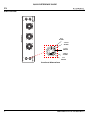 4
4
-
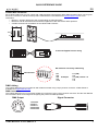 5
5
-
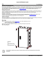 6
6
-
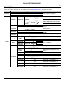 7
7
-
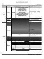 8
8
-
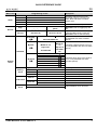 9
9
-
 10
10
-
 11
11
-
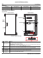 12
12
-
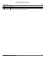 13
13
-
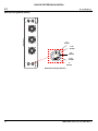 14
14
-
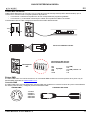 15
15
-
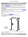 16
16
-
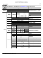 17
17
-
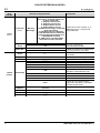 18
18
-
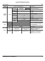 19
19
-
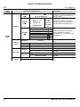 20
20
-
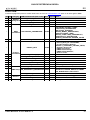 21
21
-
 22
22
-
 23
23
-
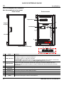 24
24
-
 25
25
-
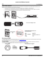 26
26
-
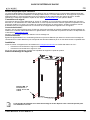 27
27
-
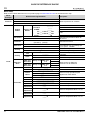 28
28
-
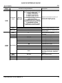 29
29
-
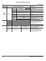 30
30
-
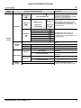 31
31
-
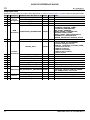 32
32
-
 33
33
-
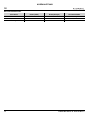 34
34
-
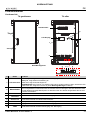 35
35
-
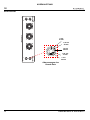 36
36
-
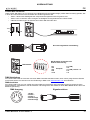 37
37
-
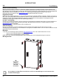 38
38
-
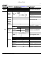 39
39
-
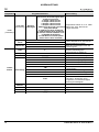 40
40
-
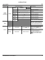 41
41
-
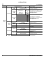 42
42
-
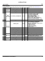 43
43
-
 44
44
-
 45
45
-
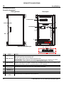 46
46
-
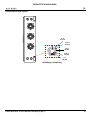 47
47
-
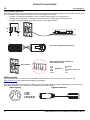 48
48
-
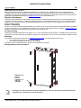 49
49
-
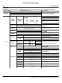 50
50
-
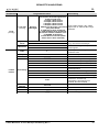 51
51
-
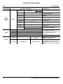 52
52
-
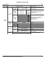 53
53
-
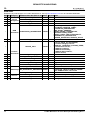 54
54
-
 55
55
-
 56
56


Iluminarc LOGIC Wall Panel Guia de referencia
- Categoría
- Focos
- Tipo
- Guia de referencia
en otros idiomas
- français: Iluminarc LOGIC Wall Panel Guide de référence
- English: Iluminarc LOGIC Wall Panel Reference guide
- Deutsch: Iluminarc LOGIC Wall Panel Referenzhandbuch
- Nederlands: Iluminarc LOGIC Wall Panel Referentie gids
Artículos relacionados

Otros documentos
-
Chauvet Professional ONAIRPANEL1IP Guía del usuario
-
Chauvet ÉPIX Guia de referencia
-
Chauvet MAVERICK Guia de referencia
-
Chauvet Professional OVATION Guia de referencia
-
-
-
Chauvet Professional COLORado Solo Batten 4 Guia de referencia
-
-
Chauvet Professional Maverick Force 2 Profile Guia de referencia