ESAB Feed 302 M11 Manual de usuario
- Categoría
- Sistema de soldadura
- Tipo
- Manual de usuario

US
Valid for serial no. 620-xxx-xxxx, 917-xxx-xxxx0459 206 187 US 100323
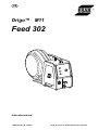
Origo™ M11
Feed 302
Instruction manual

DECLARATION OF CONFORMITY
according to the Low Voltage Directive 2006/95/EC, according to the EMC Directive 2004/108/EC
FÖRSÄKRAN OM ÖVERENSSTÄMMELSE
enligt Lågspänningsdirektivet 2006/95/EG, enligt EMC−Direktivet 2004/108/EG
Type of equipment Materialslag
Wire feeder
Brand name or trade mark Fabrikatnamn eller varumärke
ESAB
Type designation etc. Typbeteckning etc.
Feed 302 with MMC panel M11, from serial number 620 xxx xxxx (2006 week 20)
Feed 302 is a member of the ESAB product family Origo
Manufacturer or his authorised representative established within the EEA
Name, address, telephone No, telefax No: Tillverkarens namn, adress, telefon, telefax:
ESAB AB, Welding Equipment
Esabvägen, SE−695 81 LAXÅ, Sweden
Phone: +46 584 81 000, Fax: +46 584 411 924
The following harmonised standard in force within the EEA has been used in the design:
Följande harmoniserande standarderhar använts i konstruktionen:
EN 60974−5, Arc welding equipment – Part 5: Wire feeders
EN 60974−10, Arc welding equipment – Part 10: Electromagnetic compatibility (EMC) requirements
Additional information: Restrictive use, Class A equipment, intended for use in locations other than residential
By signing this document, the undersigned declares as manufacturer, or the manufacturer’s authorised
representative established within the EEA, that the equipment in question complies with the safety requirements
stated above.
Genom att underteckna detta dokument försäkrar undertecknad såsom tillverkare, eller tillverkarens representant inom
EES, att angiven materiel
uppfyller säkerhetskraven angivna ovan.
Date / Datum
Laxå 2007−03−14
Signature / Underskrift Position / Befattning
Global Director
Equipment and Automation
Kent Eimbrodt
Clarification
- 2 -

- 3 -
TOCa
Rights reserved to alter specifications without notice.
1 USER RESPONSIBILITY 4. . . . . . . . . . . . . . . . . . . . . . . . . . . . . . . . . . . . . . . . . . . .
2 SAFETY PRECAUTIONS - English 4. . . . . . . . . . . . . . . . . . . . . . . . . . . . . . . . . . .
3 PRECAUCION DE SEGURIDAD - Spanish 8. . . . . . . . . . . . . . . . . . . . . . . . . . . .
4 MESURES DE SECURITE - French 12. . . . . . . . . . . . . . . . . . . . . . . . . . . . . . . . . .
5 SAFETY 16. . . . . . . . . . . . . . . . . . . . . . . . . . . . . . . . . . . . . . . . . . . . . . . . . . . . . . . . . . .
6 INTRODUCTION 18. . . . . . . . . . . . . . . . . . . . . . . . . . . . . . . . . . . . . . . . . . . . . . . . . . .
6.1 Equipment 18. . . . . . . . . . . . . . . . . . . . . . . . . . . . . . . . . . . . . . . . . . . . . . . . . . . . . . . . . . . . . . . .
7 TECHNICAL DATA 18. . . . . . . . . . . . . . . . . . . . . . . . . . . . . . . . . . . . . . . . . . . . . . . . .
8 INSTALLATION 19. . . . . . . . . . . . . . . . . . . . . . . . . . . . . . . . . . . . . . . . . . . . . . . . . . . .
8.1 Lifting instructions 19. . . . . . . . . . . . . . . . . . . . . . . . . . . . . . . . . . . . . . . . . . . . . . . . . . . . . . . . .
9 OPERATION 20. . . . . . . . . . . . . . . . . . . . . . . . . . . . . . . . . . . . . . . . . . . . . . . . . . . . . . .
9.1 Connections and control devices 22. . . . . . . . . . . . . . . . . . . . . . . . . . . . . . . . . . . . . . . . . . . .
9.2 Water connection 23. . . . . . . . . . . . . . . . . . . . . . . . . . . . . . . . . . . . . . . . . . . . . . . . . . . . . . . . . .
9.3 Function explanations 23. . . . . . . . . . . . . . . . . . . . . . . . . . . . . . . . . . . . . . . . . . . . . . . . . . . . . .
9.4 Wire feed pressure 24. . . . . . . . . . . . . . . . . . . . . . . . . . . . . . . . . . . . . . . . . . . . . . . . . . . . . . . .
9.5 Changing / loading wire 25. . . . . . . . . . . . . . . . . . . . . . . . . . . . . . . . . . . . . . . . . . . . . . . . . . . .
9.6 Changing feed roller 25. . . . . . . . . . . . . . . . . . . . . . . . . . . . . . . . . . . . . . . . . . . . . . . . . . . . . . .
10 MAINTENANCE 26. . . . . . . . . . . . . . . . . . . . . . . . . . . . . . . . . . . . . . . . . . . . . . . . . . . .
10.1 Inspection and cleaning 26. . . . . . . . . . . . . . . . . . . . . . . . . . . . . . . . . . . . . . . . . . . . . . . . . . . .
11 ORDERING SPARE PARTS 27. . . . . . . . . . . . . . . . . . . . . . . . . . . . . . . . . . . . . . . . .
SCHEMATIC DIAGRAM 28. . . . . . . . . . . . . . . . . . . . . . . . . . . . . . . . . . . . . . . . . . . . . . . .
ORDERING NUMBER 30. . . . . . . . . . . . . . . . . . . . . . . . . . . . . . . . . . . . . . . . . . . . . . . . .
WEAR COMPONENTS 32. . . . . . . . . . . . . . . . . . . . . . . . . . . . . . . . . . . . . . . . . . . . . . . . .
ACCESSORIES 34. . . . . . . . . . . . . . . . . . . . . . . . . . . . . . . . . . . . . . . . . . . . . . . . . . . . . . .

- 4 -
US warnings
Be sure this information reaches the operator.
You can get extra copies through your supplier.
These INSTRUCTIONS are for experienced operators. If you are not fully familiar with the
principles of operation and safe practices for arc welding equipment, we urge you to read
our booklet, “Precations and Safe Practices for Arc, Cutting and Gouging, “Form 52-529.
Do NOT permit untrained persons to install, operate, or maintain this equipment. Do NOT
attempt to install or operate this equipment until you have read and fully understand these
instructions. If you do not fully understand these instructions, contact your supplier for
further information. Be sure to read the Safety Precautions before installing or operating
this equipment.
1 USER RESPONSIBILITY
This equipment will perform in conformity with the description thereof contained in this manual and
accompanying labels and/or insert when installed, operated, maintained and repaired in accordance
with the instruction provided. This equipment must be checked periodically. Malfunctioning or poorly
maintained equipment should not be used. Parts that are broken, missing, worn, distorted or
contaminated should be replaced immediately. Should such repair or replacement become necessary,
the manufacturer recommends that a telephone or written request for service advice be made to the
Authorized Distributor from whom it was purchased.
This equipment or any of its parts should not be altered without the prior written approval of the
manufacturer. The user of this equipment shall have the sole responsibility for any malfunction which
results from improper use, faulty maintenance, damage improper repair or alteration by anyone other
than the manufacturer or a service facility designated by the manufacturer.
2 SAFETY PRECAUTIONS - English
WARNING: These Safety Precautions are for your protection. They summarize precautionary
information from the references listed in Additional Safety Information section. Before performing any
installation or operating procedures, be sure to read and follow the safety precautions listed below as
well as all other manuals, material safety data sheets, labels, etc. Failure to observe Safety
Precautions can result in injury or death.
PROTECT YOURSELF AND OTHERS
Some welding, cutting and gouging precesses are noisy and require ear
protection. The arc, like the sun, emits ultraviolet (UV) and other radiation
and can injure skin and eyes. Hot metal can cause burns. Training in the
proper use of the processes and equipment is essential to prevent accidents.
Therefore:
1. Always wear safety glasses with side shields in any work area, even if welding helmets face
shields and goggles are also required.
2. Use a face shield fitted with the correct filter and cover plates to protect your eyes, face, neck
and ears from sparks and rays of the arc when operating or observing operations. Warn
bystanders not to watch the arc and not to expose themselves to the rays of the electric-arc or
hot metal.
3. Wear flameproof gauntlet type gloves, heavy long-sleeve shirt, cuffless trousers, high-topped
shoes and a welding helmet or cap for protection, to protect against arc rays and hot sparks or
hot metal. A flameproof apron may also be desirable as protection against radiated heat and
sparks.
US

- 5 -
US warnings
4. Hot sparks or metal can lodge in rolled up sleeves, trouser cuffs, or pockets. Sleeves and collars
should be kept buttoned and open pockets eliminated from the front of clothing.
5. Protect other personnel from arc rays and hot sparks with a suitable nonflammable partition or
curtains.
6. Use goggles over safety glasses when chipping slag or grinding. Chipped slag may be hot and
can fly far. Bystanders should also wear goggles over safety glasses.
FIRES AND EXPLOSIONS
Heat from flames and arcs can start fires. Hot slag or sparks can also cause
fires and explosions. Therefore:
1. Remove all combustible materials well away from the work area or cover the materials with a
protective nonflammable covering. Combusible materials include wood, clot, sawdust, liquid and
gas fuels, solvents, pants and coatings papper, etc.
2. Hot sparks or hot metal can fall through cracks or crevices in floors or wall openings and cause a
hidden smoldering fire or fires on the floor below. Make certain that such openings are protected
from hot sparks and metal.
3. Do not weld, cut or perform other hot work until the workpiece has been completely cleaned so
that there are no substances on the workpiece which might produce flammable or toxic vapors.
Do not do hot work on closed containers. They may explode.
4. Have fire extinguishing equipment handy for instant use, such as a garden hose, water pail, sand
bucket, or portable fire extinguisher. Be sure you are trained in its use.
5. Do not use equipment beyond its ratings. For example, overloaded welding cable can overheat
and create a fire hazard.
6. After completing operations, inspect the work area to make certain there are no hot sparks or hot
metal which could cause a later fire. Use fire watchers when necessary.
7. For additional information refer to NFPA Standard 51B, “Fire Prevention in Use of Cutting and
Welding Processes”, available from the National Fire Protection Association, Batterymarch Park,
Quincy, MA 02269.
ELECTRICAL SHOCK
Contact with live electrical parts and ground can cause severe injury or
death. DO NOT use AC welding current in damp areas, if movement is
confined, or if there is danger of falling. Therefore:
1. Be sure the power source frame (chassis) is connected to the ground system of the input power.
2. Connect the workpiece to a good electrical ground.
3. Connect the work cable to the workpiece. A poor or missing connection can expose you or others
to a fatal shock.
4. Use well-maintained equipment. Replace worn or damaged cables.
5. Keep everything dry, including clothing, work area, cables, torch/electrode holder and power
source.
6. Make sure that all parts of your bady are insulated from work and from ground.
7. Do not stand directly on metal or the earth while working in tight quarters or a damp area; stand
on dry boards or an insulating platform and wear rubber-soled shoes.
8. Put on dry, hole-free gloves before turning on the power.
9. Turn off the power before removing your gloves.
10. Refer to ANSI/ASC Standard Z49.1 (listed on next page) for specific grounding
recommendations. Do not mistake the work lead for a ground cable.
US

- 6 -
US warnings
ELECTRIC AND MAGNETIC FIELDS
May be dangerous. Electric current flowing through any conductor causes
localized Electric and Magnetic Fields (EMF). Welding and cutting current
creates EMF around welding cables and welding machines.
Therefore:
1. Welders having pacemakers should consult their physician before welding. EMF may interfere
with some pacemakers.
2. Exposure to EMF may have other health effects which are unknown.
3. Welders should use the following procedures to minimize exposure to EMF:
a. Route the electrode and work cables together. Secure them with tape when possible.
b. Never coil the torch or work cable around your body.
c. Do not place your body between the torch and work cables. Route cables on the same side
of your body.
d. Connect the work cable to the workpiece as close as possible to the area being welded.
e. Keep welding power source and cables as far away from your body as possible.
FUMES AND GASES
Fumes and gases, can cause discomfort or harm, particularly in confined
spaces. Do not breathe fumes and gases. Shielding gases can cause
asphyxiation.
Therfore:
1. Always provide adequate ventilation in the work area by natural or mechanical means. Do not
weld, cut or gouge on materials such as galvanized steel, stainless steel, cooper, zinc, lead
beryllium or cadmium unless positive mechanical ventilation is provided. Do not breathe fumes
from these materials.
2. Do not operate near degreasing and spraying operations. The heat or arc can react with
chlorinated hydrocarbon vapors to form phosgene, a highly toxic gas and other irritant gases.
3. If you develop momentary eye, nose or throat irritation while operating, this is an indication that
ventilation is not adequate. Stop work and take necessary steps to improve ventilation in the work
area. Do not continue to operate if physical discomfort persists.
4. Refer to ANSI/ASC Standard Z49.1 (see listing below) for specific ventilation recommendations.
5. WARNING: This product when used for welding or cutting, produces fumes or gases which
contain chemicals known to the State of Californa to cause birth defects and in some cases
cancer (California Health & Safety Code §25249.5 et seq.)
CYLINDER HANDLING
Cylinders, if mishandled, can rupture and violently release gas. Sudden
rupture of cylinder valve or relief device can injure or kill.
Therefore:
1. Use the proper gas for the process and use the proper pressure reducing regulator designed to
operate from the compressed gas cylinder. Do not use adaptors. Maintain hoses and fittings in
good condition. Follow manufacturer's operating instructions for mounting regulator to a
compressed gas cylinder.
2. Always secure cylinders in an upright position by chain or strap to suitable hand trucks,
undercarriages, benches, wall, post or racks. Never secure cylinders to work tables or fixtures
where they may become part of an electrical circuit.
3. When not in use, keep cylinder valves closed. Have valve protection cap in place if regulator is
not connected. Secure and move cylinders by using suitable hand trucks.
4. Locate cylinders away from heat, sparks and flames. Never strike an arc on a cylinder.
5. For additional information, refer to CGA Standard P-1, “Precations for Safe Handling of
Comporessed Gases in Cylinders”, which is available from Compressed Gas Association, 1235
Jefferson Davis Highway, Arlington, VA 22202.
US

- 7 -
US warnings
EQUIPMENT MAINTENANCE
Faulty or improperly maintained equipment can cause injury or death. Therefore:
1. Always have qualified personnel perform the installaion, troubleshooting and maintenance work.
Do not perform any electrical work unless you are qualified to perform such work.
2. Before performing any maintenance work inside a power source, disconnect the power source
from the incoming electrical power.
3. Maintain cables, grounding wire, connections, power cord and power supply in safe working
order. Do not operate any equipment in faulty condition.
4. Do not abuse any equipment or accessories. Keep equipment away from heat sources such as
furnaces, wet conditions such as water puddles, oil or grease, corrosive atmospheres and
inclement weather.
5. Keep all safety devices and cabinet covers in position and in good repair.
6. Use equipment only for its intended purpose. Do not modify it in any manner.
ADDITIONAL SAFETY INFORMATION
For more information on safe practices for electric arc welding and cutting equipment,
ask your supplier for a copy of “Precautions and Safe Practices for Arc Welding,
Cutting and Gouging”, Form 52-529.
The following publications, which are available from the American Welding Society, 550 N.W. LeJuene
Road, Miami, FL 33126, are recommended to you:
1. ANSI/ASC Z49.1 - “Safety in Welding and Cutting”
2. AWS C5.1 . “Recommended Practices for Plasma Arc Welding”
3. AWS C5.2 - “Recommended Practices for Plasma Arc Cutting“
4. AWS C5.3 - “Recommended Practices for Air Carbon, Arc Gouging and Cutting”
5. AWS C5.5 - “Recommended Practices for Gas Tungsten Arc Welding”
6. AWS C5.6 - “Recommended Practices for Gas Metal Arc welding”
7. AWS SP - “Safe practices” - Reprint, Welding Handbook
8. ANSI/AWS F4.1 - “Recommended Safe Practices for Welding and Cutting of Containers That
Have Held Hazardous Substances”
MEANING OF SYMBOLS
As used throughout this manual: Means Attention! Be Alert!
Means immediate hazards which, if not avoided, will result in
immediate, serious personal injury or loss of life.
Means potential hazards which could result in personal injury or loss
of life.
Means hazards which could result in minor personal injury.
US

- 8 -
US warnings
3 PRECAUCION DE SEGURIDAD - Spanish
ADVERTENCIA: Estas Precauciones de Seguridad son para su protección. Ellas hacen
resumen de información proveniente de las referencias listadas en la sección ”Información Adicional
Sobre La Seguridad”. Antes de hacer cualquier instalación o procedimiento de operación, asegúrese
de leer y seguir las precauciones de seguridad listadas a continuación así como también todo manual,
hoja de datos de seguridad del material, calcomanias, etc. El no observar las Precauciones de
Seguridad puede resultar en daño a la persona o muerte.
PROTEJASE USTED Y A LOS DEMAS
Algunos procesos de soldadura, corte y ranurado son ruidosos y requiren
protección para los oídos. El arco, como el sol , emite rayos ultravioleta (UV)
y otras radiaciones que pueden dañar la piel y los ojos. El metal caliente
causa quemaduras. EL entrenamiento en el uso propio de los equipos y sus
procesos es esencial para prevenir accidentes.
Por lo tanto:
1. Utilice gafas de seguridad con protección a los lados siempre que esté en el área de trabajo, aún
cuando esté usando careta de soldar, protector para su cara u otro tipo de protección.
2. Use una careta que tenga el filtro correcto y lente para proteger sus ojos, cara, cuello, y oídos de
las chispas y rayos del arco cuando se esté operando y observando las operaciones. Alerte a
todas las personas cercanas de no mirar el arco y no exponerse a los rayos del arco eléctrico o
el metal fundido.
3. Use guantes de cuero a prueba de fuego, camisa pesada de mangas largas, pantalón de ruedo
liso, zapato alto al tobillo, y careta de soldar con capucha para el pelo, para proteger el cuerpo
de los rayos y chispas calientes provenientes del metal fundido. En ocaciones un delantal a
prueba de fuego es necesario para protegerse del calor radiado y las chispas.
4. Chispas y partículas de metal caliente puede alojarse en las mangas enrolladas de la camisa, el
ruedo del pantalón o los bolsillos. Mangas y cuellos deberán mantenerse abotonados, bolsillos al
frente de la camisa deberán ser cerrados o eliminados.
5. Proteja a otras personas de los rayos del arco y chispas calientes con una cortina adecuada
no-flamable como división.
6. Use careta protectora además de sus gafas de seguridad cuando esté removiendo escoria o
puliendo. La escoria puede estar caliente y desprenderse con velocidad. Personas cercanas
deberán usar gafas de seguridad y careta protectora.
FUEGO Y EXPLOSIONES
El calor de las flamas y el arco pueden ocacionar fuegos. Escoria caliente y
las chispas pueden causar fuegos y explosiones.
Por lo tanto:
1. Remueva todo material combustible lejos del área de trabajo o cubra los materiales con una
cobija a prueba de fuego. Materiales combustibles incluyen madera, ropa, líquidos y gases
flamables, solventes, pinturas, papel, etc.
2. Chispas y partículas de metal pueden introducirse en las grietas y agujeros de pisos y paredes
causando fuegos escondidos en otros niveles o espacios. Asegúrese de que toda grieta y
agujero esté cubierto para proteger lugares adyacentes contra fuegos.
3. No corte, suelde o haga cualquier otro trabajo relacionado hasta que la pieza de trabajo esté
totalmente limpia y libre de substancias que puedan producir gases inflamables o vapores
tóxicos. No trabaje dentro o fuera de contenedores o tanques cerrados. Estos pueden explotar si
contienen vapores inflamables.
4. Tenga siempre a la mano equipo extintor de fuego para uso instantáneo, como por ejemplo una
manguera con agua, cubeta con agua, cubeta con arena, o extintor portátil. Asegúrese que usted
esta entrenado para su uso.
5. No use el equipo fuera de su rango de operación. Por ejemplo, el calor causado por cable
sobrecarga en los cables de soldar pueden ocasionar un fuego.
6. Después de termirar la operación del equipo, inspeccione el área de trabajo para cerciorarse de
que las chispas o metal caliente ocasionen un fuego más tarde. Tenga personal asignado para
vigilar si es necesario.
US

- 9 -
US warnings
7. Para información adicional , haga referencia a la publicación NFPA Standard 51B, “Fire
Prevention in Use of Cutting and Welding Processes”, available from the National Fire Protection
Association, Batterymarch Park, Quincy, MA 02269.
CHOQUE ELECTRICO
El contacto con las partes eléctricas energizadas y tierra puede causar daño
severo o muerte. NO use soldadura de corriente alterna (AC) en áreas
húmedas, de movimiento confinado en lugares estrechos o si hay posibilidad
de caer al suelo.
Por lo tanto:
1. Asegúrese de que el chasis de la fuente de poder esté conectado a tierra através del sistema de
electricidad primario.
2. Conecte la pieza de trabajo a un buen sistema de tierra física.
3. Conecte el cable de retorno a la pieza de trabajo. Cables y conductores expuestos o con malas
conexiones pueden exponer al operador u otras personas a un choque eléctrico fatal.
4. Use el equipo solamente si está en buenas condiciones. Reemplaze cables rotos, dañados o con
conductores expuestos.
5. Mantenga todo seco, incluyendo su ropa, el área de trabajo, los cables, antorchas, pinza del
electrodo, y la fuente de poder.
6. Asegúrese que todas las partes de su cuerpo están insuladas de ambos, la pieza de trabajo y
tierra.
7. No se pare directamente sobre metal o tierra mientras trabaja en lugares estrechos o áreas
húmedas; trabaje sobre un pedazo de madera seco o una plataforma insulada y use zapatos con
suela de goma.
8. Use guantes secos y sin agujeros antes de energizar el equipo.
9. Apage el equipo antes de quitarse sus guantes.
10. RUse como referencia la publicación ANSI/ASC Standard Z49.1 (listado en la próxima página)
para recomendaciones específicas de como conectar el equipo a tierra. No confunda el cable de
soldar a la pieza de trabajo con el cable a tierra.
CAMPOS ELECTRICOS Y MAGNETICOS
Son peligrosos. La corriente eléctrica fluye através de cualquier conductor
causando a nivel local Campos Eléctricos y Magnéticos (EMF). Las
corrientes en el área de corte y soldadura, crean EMF alrrededor de los
cables de soldar y las maquinas.
Por lo tanto:
1. Soldadores u Operadores que use marca-pasos para el corazón deberán consultar a su médico
antes de soldar. El Campo Electromagnético (EMF) puede interferir con algunos marcapasos.
2. Exponerse a campos electromagnéticos (EMF) puede causar otros efectos de salud aún
desconocidos.
3. Los soldadores deberán usar los siguientes procedimientos para minimizar exponerse al EMF:
a. Mantenga el electrodo y el cable a la pieza de trabajo juntos, hasta llegar a la pieza que
usted quiere soldar. Asegúrelos uno junto al otro con cinta adhesiva cuando sea posible.
b. Nunca envuelva los cables de soldar alrededor de su cuerpo.
c. Nunca ubique su cuerpo entre la antorcha y el cable, a la pieza de trabajo. Mantega los
cables a un sólo lado de su cuerpo.
d. Conecte el cable de trabajo a la pieza de trabajo lo más cercano posible al área de la
soldadura.
e. Mantenga la fuente de poder y los cables de soldar lo más lejos posible de su cuerpo.
US

- 10 -
US warnings
HUMO Y GASES
El humo y los gases, pueden causar malestar o daño, particularmente en
espacios sin ventilación. No inhale el humo o gases. El gas de protección
puede causar falta de oxígeno.
Por lo tanto:
1. Siempre provea ventilación adecuada en el área de trabajo por medio natural o mecánico. No
solde, corte, o trabajo por medio natural o mecánico. No solde, corte, o ranure materiales con
hierro galvanizado, acero inoxidable, cobre, zinc, plomo, berílio, o cadmio a menos que provea
ventilación mecánica positiva. No respire los gases producidos por estos materiales.
2. No opere cerca de lugares donde se aplique substancias químicas en aerosol. El calor de los
rayos del arco pueden reaccionar con los vapores de hidrocarburo clorinado para formar un
fosfógeno, o gas tóxico, y otros irritant es.
3. Si momentáneamente desarrolla inrritación de ojos, nariz o garganta mientras est á operando,
es indicación de que la ventilación no es apropiada. Pare de trabajar y tome las medidas
necesarias para mejorar la ventilación en el área de trabajo. No continúe operando si el
malestar físico persiste.
4. Haga referencia a la publicación ANSI/ASC Standard Z49.1 (Vea la lista a continuación) para
recomendaciones específicas en la ventilación.
5. ADVERTENCIA-Este producto cuando se utiliza para soldaduras o cortes, produce humos o
gases, los cuales contienen químicos conocidos por el Estado de California de causar defectos
en el nacimiento, o en algunos casos, Cancer. (California Health & Safety Code §25249.5 et
seq.)
MANEJO DE CILINDROS
Los cilindros, si no son manejados correctamente, pueden romperse y liberar
violentamente gases. Rotura repentina del cilindro, válvula, o válvula de
escape puede causar daño o muerte.
Por lo tanto:
1. Utilize el gas apropiado para el proceso y utilize un regulador diseñado para operar y reducir la
presión del cilindro de gas. No utilice adaptadores. Mantenga las mangueras y las conexiones en
buenas condiciones. Observe las instrucciones de operación del manufacturero para montar el
regulador en el cilindro de gas comprimido.
2. Asegure siempre los cilindros en posición vertical y amárrelos con una correa o cadena
adecuada para asegurar el cilindro al carro, transportes, tablilleros, paredes, postes, o armazón.
Nunca asegure los cilindros a la mesa de trabajo o las piezas que son parte del circuito de
soldadura. Este puede ser parte del circuito elélectrico.
3. Cuando el cilindro no está en uso, mantenga la válvula del cilindro cerrada. Ponga el capote de
protección sobre la válvula si el regulador no está conectado. Asegure y mueva los cilindros
utilizando un carro o transporte adecuado. Evite el manejo brusco de los
4. Localize los cilindros lejos del calor, chispas, y flamas. Nunca establezca un arco en el cilindro.
5. Para información adicional, haga referncia a la publicación CGA Standard P-1, “Precations for
Safe Handling of Comporessed Gases in Cylinders”, disponible através del Compressed Gas
Association, 1235 Jefferson Davis Highway, Arlington, VA 22202.
MANTENIMIENTO DEL EQUIPO
Equipo defectuoso o mal mantenido puede causar daño o muerte.
Por lo tanto:
1. Siempre tenga personal cualificado para efectuar la instalación, diagnóstico, y mantenimiento del
equipo. No ejecute ningún trabajo eléctrico a menos que usted esté cualificado para hacer el
trabajo.
2. Antes de dar mantenimiento en el interior de la fuente de poder, desconecte la fuente de poder
del suministro de electricidad primaria.
3. Mantenga los cables, cable a tierra, conexciones, cable primario, y cualquier otra fuente de poder
en buen estado operacional. No opere ningún equipo en malas condiciones.
4. No abuse del equipo y sus accesorios. Mantenga el equipo lejos de cosas que generen calor
como hornos, también lugares húmedos como charcos de agua, aceite o grasa, atmósferas
corrosivas y las inclemencias del tiempo.
5. Mantenga todos los artículos de seguridad y coverturas del equipo en su posición y en buenas
condiciones.
US

- 11 -
US warnings
6. Use el equipo sólo para el propósito que fue diseñado. No modifique el equipo en ninguna
manera.
INFORMACION ADICIONAL DE SEGURIDAD
Para más información sobre las prácticas de seguridad de los equipos de arco eléctrico
para soldar y cortar, pregunte a su suplidor por una copia de “Precautions and Safe
Practices for Arc Welding, Cutting and Gouging”, Form 52-529.
Las siguientes publicaciones, disponibles através de la American Welding Society, 550 N.W. LeJuene
Road, Miami, FL 33126, son recomendadas para usted:
1. ANSI/ASC Z49.1 - “Safety in Welding and Cutting”
2. AWS C5.1 . “Recommended Practices for Plasma Arc Welding”
3. AWS C5.2 - “Recommended Practices for Plasma Arc Cutting“
4. AWS C5.3 - “Recommended Practices for Air Carbon, Arc Gouging and Cutting”
5. AWS C5.5 - “Recommended Practices for Gas Tungsten Arc Welding”
6. AWS C5.6 - “Recommended Practices for Gas Metal Arc welding”
7. AWS SP - “Safe practices” - Reprint, Welding Handbook
8. ANSI/AWS F4.1 - “Recommended Safe Practices for Welding and Cutting of Containers That
Have Held Hazardous Substances”
SIGNIFICADO DE LOS SIMBOLOS
Según usted avanza en la lectura de este folleto: Los Símbolos Significan ¡Atención!
¡Esté Alerta! Se trata de su seguridad.
Significa riesgo inmediato que, de no ser evadido, puede resultar
inmediatamente en serio daño personal o la muerte.
Significa el riesgo de un peligro potencial que puede resultar en serio
daño personal o la muerte.
Significa el posible riesgo que puede resultar en menores daños a la
persona.
US

- 12 -
US warnings
4 MESURES DE SECURITE - French
ATTENTION : ces règles de sécurité ont pour objet d'assurer votre protection. Elles constituent
une synthèse des mesures de sécurité contenues dans les ouvrages de référence repris au chapitre
Informations complémentaires relatives à la Sécurité. Avant toute installation ou utilisation du matériel,
veillez à lire et à respecter les règles de sécurité énoncées ci-dessous ainsi que dans les divers
manuels, fiches de sécurité du matériel, étiquettes, etc. Le non-respect de ces précautions risque
d'entraîner des blessures graves ou mortelles.
PROTECTION INDIVIDUELLE ET DE L'ENTOURAGE
Certains procédés de soudage, découpage et gougeage sont bruyants et
requièrent le port de protections auditives. L'arc, tout comme le soleil, émet
des ultraviolets (UV) et d'autres rayonnements susceptibles de provoquer des
lésions oculaires et dermatologiques. Le métal chaud peut être à l'origine de
brûlures. Une formation à l'utilisation correcte des procédés et équipements
est essentielle pour prévenir les accidents. En conséquence :
1. Porter impérativement des lunettes avec écrans latéraux dans les zones de travail, même
lorsque le port du casque de soudage, de l'écran facial et des lunettes de protection est
obligatoire
2. Tant pour exécuter les travaux que pour y assister, porter un écran facial muni de plaques
protectrices et de verres filtrants appropriés pour protéger les yeux, le visage, le cou et les
oreilles des étincelles et du rayonnement de l'arc. Avertir les personnes se trouvant à proximité
qu'elles ne doivent pas regarder l'arc, ni s'exposer à son rayonnement ou à celui du métal
incandescent.
3. Porter des gants ignifuges à crispins, une tunique épaisse à longues manches, des pantalons
sans rebord, des chaussures à embout d'acier et un casque de soudage ou une casquette pour
se protéger du rayonnement de l'arc, des étincelles et du métal incandescent. Le port d'un tablier
ininflammable est également recommandé afin de se protéger des étincelles et du rayonnement
thermique.
4. Les étincelles ou projections de métal en fusion risquent de se loger dans les manches
retroussées, les bords relevés de pantalons ou dans les poches. Il convient donc de boutonner
complètement les manches et le col, et de porter des vêtements sans poches à l'avant.
5. Protéger du rayonnement de l'arc et des étincelles les personnes se trouvant à proximité à l'aide
d'un écran ou d'un rideau ininflammable approprié.
6. Porter des oculaires et des lunettes de protection pendant le meulage du laitier. Les particules
meulées, souvent brûlantes, peuvent être projetées à des distances importantes, de sorte que
les personnes se trouvant à proximité doivent également porter des lunettes de protection.
INCENDIES ET EXPLOSIONS
La chaleur dégagée par les flammes et les arcs peuvent être à l'origine
d'incendies. Le laitier incandescent et les étincelles peuvent également
provoquer incendies et explosions. En conséquence :
1. Éloigner suffisamment tous les matériaux combustibles de la zone de travail ou les recouvrir
complètement d'une bâche ignifuge. Ce type de matériaux comprend le bois, les vêtements, la
sciure, les carburants sous forme liquide et gazeuse, les peintures, les enduits, le papier, etc.
2. Les étincelles ou projections de métal en fusion peuvent tomber dans les fissures du sol ou des
murs et déclencher une combustion lente dans les planchers ou à l'étage inférieur. Veiller à
protéger ces ouvertures pour que les étincelles et projections n'y pénètrent pas.
3. Ne pas procéder à des travaux de soudage, de découpage et autres travaux à chaud tant que la
surface n'est pas complètement nettoyée et débarrassée des substances susceptibles de
produire des vapeurs inflammables ou toxiques. Ne pas effectuer de travaux à chaud sur des
conteneurs fermés pour éviter tout risque d'explosion.
4. Conserver à portée de main un équipement d'extinction – tuyau d'arrosage, seau d'eau ou de
sable, extincteur portatif, etc. et s'assurer d'en connaître l'utilisation.
5. Ne pas utiliser l'équipement au-delà de ses spécifications. Par exemple, un câble de soudage
surchargé est susceptible de surchauffer et d'être à l'origine d'un incendie.
US

- 13 -
US warnings
6. Une fois le travail terminé, inspecter la zone de travail pour s'assurer qu'aucune étincelle ou
projection de métal ne risque de déclencher un incendie. Le cas échéant, utiliser des systèmes
de détection d'incendie.
7. Pour toute information supplémentaire, voir la norme NFPA 51B relative à la prévention des
incendies lors de travaux de découpage et de soudage, disponible auprès de la National Fire
Protection Association, Batterymarch Park, Quincy, MA 02269 – USA.
CHOC ELECTRIQUE
Tout contact avec des éléments sous tension et la masse peut provoquer des
blessures graves ou mortelles. NE PAS utiliser de courant de soudage CA
dans des zones humides, des lieux exigus ou lorsqu'il existe un risque de
chute. En conséquence :
1. Vérifier que le châssis du générateur est bien relié au dispositif de mise à la masse de
l'alimentation.
2. Assurer une mise à la masse correcte de la pièce à souder.
3. Connecter le câble de soudage à la pièce à souder. Un raccordement médiocre ou inexistant
constitue un risque mortel pour l'utilisateur et son entourage.
4. Utiliser du matériel correctement entretenu. Remplacer les câbles usés ou endommagés.
5. Empêcher l'apparition de toute humidité, notamment sur les vêtements, dans la zone de travail,
sur les câbles, la torche de soudage, le porte-électrode et le générateur.
6. S'assurer que le corps est totalement isolé de la pièce à souder et de la masse.
7. Éviter tout contact direct avec du métal ou la masse lors de travaux dans des endroits exigus et
en zone humide ; se tenir sur des panneaux ou sur une plate-forme isolante et porter des
chaussures à semelles en caoutchouc.
8. Enfiler des gants secs et sans trous avant de mettre l'équipement sous tension.
9. Mettre l'équipement hors tension avant de retirer les gants.
10. Voir la norme ANSI/ASC Z49.1 (voir page suivante) pour les recommandations de mise à la
masse. Ne pas confondre le câble de soudage et le câble de masse.
CHAMPS ELECTRIQUES ET MAGNETIQUES
Danger. Le courant électrique parcourant les conducteurs génère localement
des champs électriques et magnétiques (EMF). Le courant de soudage et de
découpe crée des EMF autour des câbles de soudage et des postes à souder.
En conséquence :
1. Les porteurs de stimulateurs cardiaques consulteront leur médecin avant d'effectuer des travaux
de soudage. Les EMF peuvent en effet provoquer des interférences.
2. L'exposition aux EMF peut également avoir des effets méconnus sur la santé.
3. Les soudeurs respecteront les procédures suivantes pour réduire l'exposition aux EMF :
a. Rassembler en faisceau les câbles de soudage et d'électrode. Si possible, les attacher avec
du ruban adhésif.
b. Ne jamais enrouler le câble de la torche ou le câble de soudage autour du corps.
c. L'utilisateur ne doit jamais se trouver entre le câble de la torche et le câble de soudage.
Faire passer tous les câbles du même côté du corps.
d. Connecter le câble de soudage à la pièce à souder, au plus près de l'endroit du soudage.
e. S'éloigner au maximum du générateur et des câbles.
US

- 14 -
US warnings
FUMEES ET GAZ
L'inhalation des fumées et gaz peut provoquer des malaises et des
dommages corporels, surtout lors de travaux dans les espaces confinés. Ne
pas les respirer. Les gaz inertes peuvent causer l'asphyxie.
En conséquence :
1. Assurer une aération adéquate de la zone de travail par une ventilation naturelle ou mécanique.
Ne pas effectuer de travaux de soudage, découpage ou gougeage sur des matériaux tels que
l'acier galvanisé, le cuivre, le zinc, le plomb, le béryllium et le cadmium en l'absence d'une
ventilation mécanique adéquate. Ne pas inhaler les fumées dégagées par ces matériaux.
2. Ne pas travailler à proximité d'opérations de dégraissage et de pulvérisation étant donné que la
chaleur dégagée et l'arc peut réagir avec les hydrocarbures chlorés pour former du phosgène –
un gaz particulièrement toxique – et d'autres gaz irritants.
3. Une irritation momentanée des yeux, du nez ou de la gorge provoquée par les travaux est le
signe d'une ventilation inappropriée. Dans ce cas, il convient d'arrêter le travail et de prendre les
mesures nécessaires pour améliorer l'aération. Ne pas poursuivre le travail si le malaise persiste.
4. Voir la norme ANSI/ASC Z49.1 (voir ci-dessous) pour les recommandations de ventilation.
5. ATTENTION : utilisé dans des opérations de soudage et de découpage, ce produit dégage des
fumées et gaz qui contiennent des substances chimiques reconnues par l'État de Californie
comme pouvant être à l'origine de malformations congénitales et de cancers (California Health &
Safety Code §25249.5 et seq.).
MANIPULATION DES BOUTEILLES DE GAZ
Une erreur de manutention des bouteilles de gaz peut les endommager et
entraîner une libération violente du gaz. La rupture soudaine de la soupape
ou du détendeur peut provoquer des blessures graves ou mortelles.
En conséquence :
1. Utiliser le gaz approprié à la pression adéquate, celle-ci étant réglée par un détendeur adapté au
type de bouteille utilisée. Ne pas utiliser d'adaptateurs. Garder les tuyaux et accessoires en bon
état. Pour le montage du détendeur sur une bouteille de gaz comprimé, suivre les instructions du
fabricant.
2. Fixer les bouteilles verticalement – au moyen d'une chaîne ou d'une sangle – à un chariot à bras,
un châssis de roulement, un banc, un mur, un piquet ou un rack. Ne jamais attacher les
bouteilles aux établis et éléments susceptibles de les intégrer à un circuit électrique.
3. Conserver les bouteilles fermées lorsqu'elles ne sont pas utilisées. Les fermer par un bouchon
lorsqu'elles ne sont pas raccordées. Attacher et déplacer les bouteilles à l'aide de chariots
adéquats.
4. Éloigner les bouteilles des sources de chaleur, d'étincelles et de flammes nues. Ne jamais
déclencher d'arc sur une bouteille de gaz.
5. Pour plus d'informations sur les précautions d'utilisation des bouteilles de gaz comprimé, voir la
norme CGA P-1, disponible auprès de la Compressed Gas Association, 1235 Jefferson Davis
Highway, Arlington, VA 22202 – USA.
ENTRETIEN DE L'EQUIPEMENT
Un équipement mal entretenu peut provoquer des blessures graves ou mortelles. En
conséquence :
1. Confier l'installation, les dépannages et l'entretien à du personnel qualifié. Ne pas effectuer de
travaux électriques si vous ne possédez pas les compétences requises.
2. Mettre l'équipement hors tension avant toute intervention d'entretien sur le générateur.
3. Maintenir en bon état de fonctionnement les câbles, câbles de masse, connexions, cordons
d'alimentation et générateurs. Ne jamais utiliser d'équipements défectueux.
4. Ne jamais surcharger les équipements et accessoires. Conserver les équipements à l'écart des
sources de chaleur – notamment des fours –, des flaques d'eau, des traces d'huile ou de graisse,
des atmosphères corrosives et des intempéries.
5. Laisser en place tous les dispositifs de sécurité et tous les panneaux du tableau de commande
en veillant à les garder en bon état.
6. Utiliser l'équipement conformément à l'usage prévu ; n'y apporter aucune modification
quelconque.
US

- 15 -
US warnings
INFORMATIONS COMPLEMENTAIRES RELATIVES A LA SECURITE Pour plus
d'informations relatives aux règles de sécurité pour les travaux de gougeage, de
découpage et de soudage à l'arc électrique, demander au fournisseur une copie du
formulaire 52/529.
L'American Welding Society, 550 N.W. LeJuene Road, Miami, FL 33126 – USA, publie les documents
suivants dont la lecture est également recommandée :
1. ANSI/ASC Z49.1 - ”Safety in Welding and Cutting”
2. AWS C5.1 . ”Recommended Practices for Plasma Arc Welding”
3. AWS C5.2 - ”Recommended Practices for Plasma Arc Cutting”
4. AWS C5.3 - ”Recommended Practices for Air Carbon, Arc Gouging and Cutting”
5. AWS C5.5 - ”Recommended Practices for Gas Tungsten Arc Welding”
6. AWS C5.6 - ”Recommended Practices for Gas Metal Arc welding”
7. AWS SP - ”Safe practices” - Réédition, Manuel de soudage
8. ANSI/AWS F4.1 - ”Recommended Safe Practices for Welding and Cutting of Containers That
Have Held Hazardous Substances”
SYMBOLES
Signification des symboles utilisés dans ce manuel : = Attention ! Rester prudent !
= danger immédiat ; risque de blessures graves ou mortelles.
= danger potentiel ; risque de blessures graves ou mortelles.
= danger ; risque de blessures légères.
US

- 16 -
bm36d1aa
5 SAFETY
Users of ESAB welding equipment have the ultimate responsibility for ensuring that anyone who
works on or near the equipment observes all the relevant safety precautions. Safety precautions
must meet the requirements that apply to this type of welding equipment. The following recommen
dations should be observed in addition to the standard regulations that apply to the workplace.
All work must be carried out by trained personnel well-acquainted with the operation of the welding
equipment. Incorrect operation of the equipment may lead to hazardous situations which can result
in injury to the operator and damage to the equipment.
1. Anyone who uses the welding equipment must be familiar with:
its operation
location of emergency stops
its function
relevant safety precautions
welding
2. The operator must ensure that:
no unauthorized person is stationed within the working area of the equipment when it is
started up.
no-one is unprotected when the arc is struck
3. The workplace must:
be suitable for the purpose
be free from drafts
4. Personal safety equipment
Always wear recommended personal safety equipment, such as safety glasses, flame-proof
clothing, safety gloves. Note! Do not use safety gloves when replacing wire.
Do not wear loose-fitting items, such as scarves, bracelets, rings, etc., which could become
trapped or cause burns.
5. General precautions
Make sure the ground cable is connected securely.
Work on high voltage equipment may only be carried out by a qualified electrician.
Appropriate fire extinquishing equipment must be clearly marked and close at hand.
Lubrication and maintenance must not be carried out on the equipment during operation.
Read and understand the instruction manual
before installing or operating.
Class A equipment is not intended for use in residential locations
where the electrical power is provided by the public low-voltage
supply system. There may be potential difficulties in ensuring
electromagnic compatibility of class A equipment in those locations,
due to conducted as well as radiated disturbances.
US

- 17 -
bm36d1aa
This product is solely intended for arc welding. Any other use may result in personal
injury and / or equipment damage.
READ AND UNDERSTAND THE INSTRUCTION MANUAL BEFORE INSTALLING OR OPERATING.
ARC WELDING AND CUTTING CAN BE INJURIOUS TO YOURSELF AND OTHERS. TAKE
PRECAUSIONS WHEN WELDING. ASK FOR YOUR EMPLOYER'S SAFETY PRACTICES
WHICH SHOULD BE BASED ON MANUFACTURERS' HAZARD DATA.
ELECTRIC SHOCK - CAN KILL
INSTALL AND EARTH THE WELDING UNIT IN ACCORDANCE WITH APPLICABLE
STANDARDS.
DO NOT TOUCH LIVE ELECTRICAL PARTS OR ELECTRODES WITH BARE SKIN,
WET GLOVES OR WET CLOTHING.
INSULATE YOURSELF FROM EARTH AND THE WORKPIECE.
ENSURE YOUR WORKING STANCE IS SAFE.
FUMES AND GASES - CAN BE DANGEROUS TO HEALTH
KEEP YOUR HEAD OUT OF THE FUMES.
USE VENTILATION, EXTRACTION AT THE ARC, OR BOTH, TO TAKE FUMES AND
GASES AWAY FROM YOUR BREATHING ZONE AND THE GENERAL AREA.
ARC RAYS - CAN INJURE EYES AND BURN SKIN.
PROTECT YOUR EYES AND BODY. USE THE CORRECT WELDING SCREEN AND
FILTER LENS AND WEAR PROTECTIVE CLOTHING.
PROTECT BYSTANDERS WITH SUITABLE SCREENS OR CURTAINS.
FIRE HAZARD
SPARKS (SPATTER) CAN CAUSE FIRE. MAKE SURE THEREFORE THAT THERE ARE
NO INFLAMMABLE MATERIALS NEARBY.
NOISE - EXCESSIVE NOISE CAN DAMAGE HEARING
PROTECT YOUR EARS. USE EARMUFFS OR OTHER HEARING PROTECTION.
WARN BYSTANDERS OF THE RISK.
MALFUNCTION - CALL FOR EXPERT ASSISTANCE IN THE EVENT OF MALFUNCTION.
PROTECT YOURSELF AND OTHERS!
Do not dispose of electrical equipment together with normal waste!
In observance of European Directive 2002/96/EC on Waste Electrical and Electronic
Equipment and its implementation in accordance with national law, electrical equipment
that has reached the end of its life must be collected separately and returned to an
environmentally compatible recycling facility. As the owner of the equipment, you should
get information on approved collection systems from our local representative.
By applying this European Directive you will improve the environment and human
health!
ESAB can provide you with all necessary welding protection and accessories.
US

- 18 -
bm36d1aa
6 INTRODUCTION
The Feed 302 wire feed unit with control panel M11 is
intended for MIG/MAG-welding together with step controlled
welding power sources.
They come in different variants, see the spare parts list on
page 30.
The wire feed units are sealed and contain two-wheel
drive wire feed mechanisms as well as control electronics.
They can be used together with wire on ESAB's
MarathonPac, or on wire bobbin (standard Ø 12 inch, accessory Ø 17 inch).
The wire feed unit can be installed either at the power source, suspended above the
workplace, on a support arm or on the floor with or without wheel set.
ESAB's accessories for the product can be found on page 34.
6.1 Equipment
The Feed 302 wire feed unit is supplied with:
Instruction manual
Stickers with recommended wear parts.
Instruction manuals in other languages can be downloaded from the website,
www.esab.com.
7 TECHNICAL DATA
Feed 302
Power supply 42 V 50 - 60 Hz
Power requirement 150 VA
Motor current I
max
3.5 A
Settings data
Wire feed speed
Burnback time
Creep start
2/4 stroke
75-984 inch/min
0-0.5 s
OFF or ON
2 stroke or 4 stroke
Welding gun connection EURO
Max. diameter wire bobbin 12 inch (*17 inch)
Wire dimension .023 - .045 inch
Weight 31.5 Ibs
Dimensions (l x w x h) 27.2 x 10.8 x 16.6 inch
Shielding gas
max pressure
All types intended for MIG/MAG welding
73 PSI
Coolant
max pressure
50% water / 50% glycol
73 PSI
Permissible load at
35% duty cycle
400 A
Enclosure class
with wire bobin *440mm
IP23
IP2X
US

- 19 -
bm36d1aa
* Accessory, see page 34.
Duty cycle
The duty cycle refers to the time as a percentage of a ten-minute period that you can weld at a cer
tain load without overloading. The duty cycle is valid for 104° F.
Enclosure class
The IP code indicates the enclosure class, i. e. the degree of protection against penetration by solid
objects or water. Equipment marked IP 23 is designed for indoor and outdoor use.
Equipment marked IP2X is designed for indoor use.
8 INSTALLATION
The installation must be done by a professional.
WHEN WELDING IN AN ENVIRONMENT WITH INCREASED ELECTRICAL DANGER,
ONLY POWER SOURCES INTENDED FOR THIS ENVIRONMENT MAY BE USED.
THESE POWER SOURCES ARE MARKED WITH THE SYMBOL
8.1 Lifting instructions
To avoid personal injury and / or equipment damage, lift using method and
attachment points shown here.
US

- 20 -
bm36d1aa
Ordering number for the lifting eye can be found on page 34.
Note! If another mounting device is used, this should be insulated from the wire feed
unit.
If equipment is placed on a surface that slopes more than 10°, toppling over may
occur. Personal injury and / or significant damage to equipment is possible
9 OPERATION
General safety regulations for the handling of the equipment can be found on
page 4. Read through before you start using the equipment!
TO AVOID SHOCK, DO NOT TOUCH ELECTRODE WIRE OR PARTS IN
CONTACT WITH IT, OR UNINSULATED CABLE OR CONNECTIONS.
ASSURE THAT THE SIDE PANELS ARE CLOSED DURING OPERATION.
TO PREVENT THE REEL FROM SLIDING OFF THE HUB:
LOCK THE REEL IN PLACE BY TURNING THE RED
KNOB AS SHOWN ON THE WARNING LABEL
ATTACHED NEXT TO THE HUB.
ROTATING PARTS CAN CAUSE INJURY, TAKE GREAT CARE.
THERE IS A RISK OF TIPPING IF THE WIRE FEED UNIT IS FITTED WITH A
COUNTERBALANCE ARM. SECURE THE EQUIPMENT, ESPECIALLY IF USED ON
AN UNEVEN OR SLOPING SURFACE.
US

- 21 -
bm36d1aa
BEFORE MAKING ANY CONNECTIONS BETWEEN THE WIRE FEEDER AND THE
WELDING POWER SOURCE, TURN OFF POWER TO THE WELDING POWER
SOURCE AND THE WIRE FEEDER.
BE SURE TO PROPERLY INSULATE THIS CONNECTION BEFORE APPLYING
POWER TO THE POWER SOURC. UNINSULATED CABLE AND PARTS CAN ARC
WHEN CONTACTING A GROUNDED SURGACE. THE ARC MAY DAMAGE EYES OR
START A FIRE. BODY CONTACT WITH AN UNINSULATED WELD CABLE
CONNECTOR, OR UNCOVERED CONDUCTOR CAN SHOCK, POSSIBLY FATALLY.
UNLESS STARTING TO WELD, DO NOT ALLOW THE WELDING WIRE TO TOUCH A
GROUNDED METAL SURFACE. THE WELDING WIRE BECOMES ELECTRICALLY
HOT WHEN THE SEDONDARY CONTACT IS CLOSED. KEEP FINGERS CLEAR OF
THE DRIVE ROLLS; THEY WILL START TURNING WHEN THE TORCH TRIGGER IS
PRESSED.
WHEN THE POWER SWITCH IS ON, AND TORCH TRIGGER IS DEPRESSED, THE
ELECTRODE WIRE BECOMES ELECTRICALLY HOT AND THE WIRE FEED ROLLS
ARE ACTIVATED. DO NOT TOUCH THE WIRE AS IT MAY CAUSE A POSSIBILY
FATAL SHOCK. UNLESS WELDING, DO NOT ALLOW WIRE TO TOUCH A
GROUNDED METAL SURFACE AS IT WILL CAUSE AN ARC FLASH. KEEP CLEAR
OF FEED ROLLS AND DRIVE GEARS.
PRIOR TO WELDING, IT IS IMPERATIVE THAT PROPER PROTECTIVE CLOTHING
(WELDING COAT AND GLOVES) AND EYE PROTECTION (GLASSES AND/OR
WELDING HELMET) BE PUT ON. FAILURE TO COMPLY MAY RESULT IN SERIOUS
INJURY.
FAILURE TO SHUT OFF SHIELD GAS IN A CONFINED SPACE MAY RESULT IN A
BUILD-UP OF FUMES, DISPLACING OXYGEN.
US

- 22 -
bm36d1aa
Do not terminate the arc by removing the torch from the weld area. Release the
torch trigger to stop welding before removing the torch.
When moving the equipment use intended handle. Never pull on the gun.
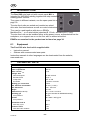
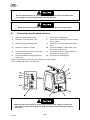
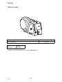
9.1 Connections and control devices
1 Knob for setting burnback time 7 Connection for welding gun
2 Switch for creep start OFF / ON 8 Connection for welding current from power
source, (OKC)
3 Knob for setting wire feed speed. 9 Connection for control cable from power
source
4 Switch for 2-stroke / 4-stroke 10 Connection RED for cooling water to po
wer source (cooling unit)
5 Connection BLUE, with ELP* for cooling
water to the welding gun
11 Connection BLUE for cooling water from
power source (cooling unit)
6 Connection RED for cooling water from
welding gun
12 Connection for shielding gas
NOTE! Cooling water connections only available on certain models.
* ELP = ESAB Logic Pump, see point 9.2.
Make sure the torch chosen is of the proper rating for the welding current to be
used, has the proper size and type of liner, the proper contact tip and the proper
guide tube.
US

- 23 -
bm36d1aa
9.2 Water connection
When connecting a water-cooled welding gun, the power source's main power
supply switch must be in the Off position and the cooling unit switch must be in
position “ELP/0”.
The wire feed unit with water connection is equipped with a detection system ELP
(ESAB Logic Pump) which checks that the water hoses are connected. When
connecting a water-cooled welding gun, the water pump starts.
Detection only works with power sources that are equipped with ELP.
9.3 Function explanations
Burnback time
Burnback time is a delay between the time when the wire starts to brake until the
time when the power source switches off the welding voltage. Too short burnback
time results in a long wire stickout after completion of welding, with a risk of the wire
being caught in the solidifying weld pool. Too long a burnback time results in a
shorter stickout, with increased risk of the arc striking back to the contact tip.
Slow run in
Slow run in start means that the wire is fed at low speed until it comes into electrical
contact with the workpiece and then the speed increases to the set speed.
2 stroke
With 2 stroke, the gas flow and wire feed start when the trigger switch is pressed in
and end when it is released.
4 stroke
With 4 stroke, the gas flow starts when the trigger switch is pressed in and the wire
feed starts when it is released. The welding process continues until the switch is
pressed in again, the wire feed stops and when the switch is released the gas stops
flowing.
Wire feed speed
This sets the required feed speed of the filler wire in m/minute.
US

- 24 -
bm36d1aa
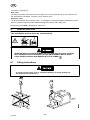
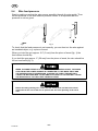
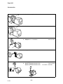
9.4 Wire feed pressure
Start by making sure that the wire moves smoothly through the wire guide. Then
set the pressure of the wire feeder's pressure rollers. It is important that the
pressure is not too great.
Fig 1 Fig 2
To check that the feed pressure is set correctly, you can feed out the wire against
an insolated object, e.g. a piece of wood.
When you hold the gun approx. 0.2” (5 mm) from the piece of wood (fig. 1) the
feed rollers should slip.
If you hold the gun approx. 2” (50 mm) from the piece of wood, the wire should be
fed out and bend (fig. 2).
WHEN THE WIRE FEEDER IS CONNECTED TO THE POWER SOURCE, THE WORK
LEAD FROM THE POWER SOURCE IS CONNECTED TO THE WORK PIECE AND
THE POWER SOURCE IS ENERGICED, CLOSING THE TORCH TRIGGER WILL
CAUSE THE WELDING WIRE TO BECOME ELECTRICALLY HOT AND WILL CAUSE
THE DRIVE ROLLS TO TURN. KEEP FINGERS CLEAR!
Before threading welding wire, make sure the chisel point and burrs have been
removed from the end of the wire to prevent the wire from jamming in the torch
liner.
US

- 25 -
bm36d1aa
9.5 Changing / loading wire
RISK OF CRUSHING! DO NOT USE SAFETY GLOVES WHEN REPLACING
WIRE, FEED ROLLERS AND WIRE BOBBINS.
Open the side panel.
Disconnect the pressure sensor by folding it backwards, the pressure rollers
slide up.
Straighten out the new wire 4-8 inch. File away burrs and sharp edges from the
end of the wire before inserting it into the wire feed unit.
Make sure that the wire goes properly into the feed roller's track and into the
outflow nozzle or wire guide.
Secure the pressure sensor.
Close the side panel.
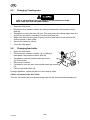
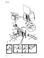
9.6 Changing feed roller
Open the side panel.
Disconnect the pressure sensor (1) by folding it
backwards, the pressure rollers slide up.
Completely undo the socket head cap screw
(2) in the centre.
Remove the washer.
Completely undo the two outer socket head cap screws
(3).
Pull out the feed rollers (4).
During installation, repeat the above in the reverse order.
Choice of tracks in the feed roller
Turn the feed roller with the dimensioning mark for the required track towards you.
US

- 26 -
bm36d1aa
10 MAINTENANCE
BE SURE THE BRANCH CIRCUIT OR MAIN DISCONNECT SWITCH IS OFF OR
ELECTRICAL INPUT CIRCUIT FUSES ARE REMOVED FROM THE POWER SOURCE
MAIN SUPPLY BEFORE ATTEMPTING ANY INSPECTION OR WORK ON THE
INSIDE OF THE WIRE FEEDER. PLACING THE POWER SWITCH ON THE WELDING
MACHINE IN THE OFF POSISION DOES NOT REMOVE ALL POWER FROM INSIDE
OF THE EQUIPMENT.
INSPECTION, TROUBLESHOOTING, AND REPAIR OF THIS EQUIPMENT SHOULD
BE UNDERTAKEN BY A COMPETENT INDIVIDUAL HAVING AT LEAST GENERAL
EXPERIENCE IN THE MAINTENANCE AND REPAIR OF SEMI-CONDUCTOR
ELECTRONIC EQUIPMENT. MAINTENANCE OR REPAIR SHOULD NOT BE
UNDERTAKEN BY ANYONE NOT HAVING SUCH QUALIFICATIONS.
Supplier warranty is void if customer attempts any work on product during the
warranty period.
Regular maintenance is important for safe, reliable operation.
10.1 Inspection and cleaning
IF UNINSULATED CABLE AND PARTS ARE NOT REPLACED, AN ARC CAUSED BY
A BARED CABLE OR PART TOUCHING A GROUNDED SURFACE MAY DAMAGE
UNPROTECTED EYES OR START A FIRE. BODY CONTACT WITH A BARED
CABLE, CONNECTOR, OR UNCOVERED CONDUCTOR CAN SHOCK, POSSIBLY
FATALLY.
Wire feed unit
Check regularly to insure that the wire feed unit is not clogged with dirt.
Cleaning and replacement of the wire feed unit mechanism's worn parts should
take place at regular intervals in order to achieve trouble-free wire feed. Note
that if pre-tensioning is set too high, this can result in abnormal wear on the
pressure roller, feed roller and wire guide.
US

- 27 -
bm36d1aa
The brake hub
The hub is adjusted when delivered, if
readjustment is required, follow the instructions
below. Adjust the brake hub so that wire is slightly
slack when wire feed stops.
Adjusting the braking torque:
Turn the red handle to the locked position.
Insert a screwdriver into the springs in the hub.
Turn the springs clockwise to reduce the braking torque
Turn the springs counter clockwise to increase the braking torque.
NB: Turn both springs the same amount.
Welding gun
Cleaning and replacement of the welding gun's wear parts should take place at
regular intervals in order to achieve trouble-free wire feed. Blow the wire guide
clean regularly and clean the contact tip.
11 ORDERING SPARE PARTS
Do not make any repairs to equipment unless you are fully qualified, as described
in the maintenance section.
Feed 302 is designed and tested in accordance with the international and European
standards IEC/EN 60974-5 and IEC/EN 60974-10. It is the obligation of the service unit
which has carried out the service or repair work to make sure that the product still
conforms to the said standard.
When ordering replacement parts, order by part number and part name, as
illustrated on the figure. Always provide the series or serial number on the unit on
which the parts will be used. The serial number is stamped on the rating plate.
US

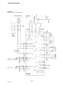
Schematic diagram
- 28 -
bm36e11a
Feed 302
valid for serial no. 620-xxx-xxxx

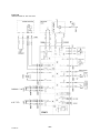
- 29 -
bm36e11a
Feed 302
valid for serial no. 917-xxx-xxxx

Feed 302
Ordering number
- 30 -
bm36oa
1.
Type Ordering number
Origo Feed 302, M11 0459 116 381
Type File name
Spare parts list 0459 206 990
The spare parts list is available on the Internet at www.esab.com

- 31 -
p

Feed 302
Wear components
- 32 -
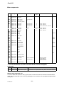
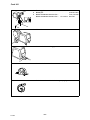
bm36whk1a
Item Ordering no. Denomination Wire type Groove
type
Wire dimensions Notes
HK1 0455 889 001* Insert tube Fe, Ss & cored
0455 894 001* Insert tube Al
HK2 0455 886 001* Outlet nozzle Fe, Ss & cored
0455 885 001* Outlet nozzle Al
HK3 0369 716 001 Feed roller geared
HK4 0369 557 001 Feed roller Fe, Ss & cored V Ø .023 - .030 inch
0369 557 002 Feed roller Fe, Ss & cored V Ø .030 - .040 inch
0369 557 003 Feed roller Fe, Ss & cored V Ø .040 / .045 & .052 / 1/16 inch
0369 557 004 Feed roller Cored V-Knurled Ø .040 - .045 inch
0369 557 011 Feed roller Al U Ø .030 - .035 inch
0369 557 006 Feed roller Al U Ø .040 - .045 inch
HK5 0193 104 002 Washer
HK6 0455 898 001
0215 201 202
Screw
O-ring
(M5x12)
HK7 0455 881 001 Cover plate
HK8 Screw M4x12
HK9 Screw M3x16
HK10 0466 074 001 Insert tube
HK11 0369 728 001 Pressure roller Flat
0466 262 001 Pressure roller Knurled
HK12 0455 053 880 Geared adapter
HK13 Locking washer SGA D8
HK14 Holder
HK15 Shaft
HK16 0455 896 001 Spring
HK17 Nut M10
HK18 0458 748 002 Insulating washer
HK19 0458 748 001 Insulating bushing
HK20 0156 602 001
0332 318 001
Inlet nozzle
Inlet nozzle
Fe, Ss, Al & Cored
Fe, Ss & Cored
Ø 5/64 inch plastic
for .023-1/16 inch
Ø 3/32 inch steel
for .045 - 5/64 inch
HK21 0191 496 114 Woodruff wedge
* Insert tube 0455 889 001 and outlet nozzle 0455 886 001 must be used together.
Insert tube 0455 894 001 and outlet nozzle 0455 885 001 must be used together.
PARTS SET
Item Ordering no. Denomination Notes
HK100 0469 833 880 Pressure arm complete Includes items HK11 (flat pressure roller), HK12, HK13, HK14 and HK15
Welding with aluminium wire
In order to weld with aluminium wire, proper rollers, nozzles and liners for aluminium wire MUST be
used, It is recommended to use 10 ft long welding gun for aluminium wire, equipped with appropriate
wear parts.

Feed 302
- 33 -
bm36whk1a

Feed 302
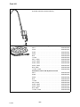
Accessories
- 34 -
bm36aa
1 Bobbin cover, plastic Ø 12 inch . . . . . . . . . . . . 0458 674 880
1 Bobbin cover, metal Ø 12 inch . . . . . . . . . . . . . 0459 431 880
1
2
Bobbin holder . . . . . . . . . . . . . . . . . . . . . . . . . . .
Adapter for 11 Ibs bobbin . . . . . . . . . . . . . . . . . .
0458 704 880
0455 410 001
1 Adapter for 17 inch bobbin . . . . . . . . . . . . . . . . . 0459 233 880
1
2
Lifting eye . . . . . . . . . . . . . . . . . . . . . . . . . . . . . . .
Quick connector MarathonPac . . . . . . . . . . .
Quick connector MarathonPac US version
0458 706 880
F102 440 880
899 F50

Feed 302
- 35 -
bm36aa
1
2
3
Turning piece . . . . . . . . . . . . . . . . . . . . . . . . . . . .
Guide pin . . . . . . . . . . . . . . . . . . . . . . . . . . . . . . . .
Quick connector MarathonPac . . . . . . . . . . .
Quick connector MarathonPac US version
0458 703 880
0156 654 883
F102 440 880
899 F50
1 Wheel kit . . . . . . . . . . . . . . . . . . . . . . . . . . . . . . . . 0458 707 880
1 Strain relief for welding gun . . . . . . . . . . . . . . 0457 341 881
Strain relief bracket for connection set . . . . 0459 234 880
Push button for cold wire feed or gas purging 0459 465 880

Feed 302
- 36 -
bm36aa
Counter balance device . . . . . . . . . . . . . . . . . .
(includes mast and counter balance)
0458 705 880
Connection set for 400 A power sources
5.6 ft . . . . . . . . . . . . . . . . . . . . . . . . . . . . . . . . . . . . .
16.4 ft . . . . . . . . . . . . . . . . . . . . . . . . . . . . . . . . . . .
32.8 ft . . . . . . . . . . . . . . . . . . . . . . . . . . . . . . . . . . .
49.2 ft . . . . . . . . . . . . . . . . . . . . . . . . . . . . . . . . . . .
82 ft . . . . . . . . . . . . . . . . . . . . . . . . . . . . . . . . . . . . .
114.8 ft . . . . . . . . . . . . . . . . . . . . . . . . . . . . . . . . . .
5.6 ft, water . . . . . . . . . . . . . . . . . . . . . . . . . . . . . .
16.4 ft, water . . . . . . . . . . . . . . . . . . . . . . . . . . . . .
32.8 ft, water . . . . . . . . . . . . . . . . . . . . . . . . . . . . .
49.2 ft, water . . . . . . . . . . . . . . . . . . . . . . . . . . . . .
82 ft, water . . . . . . . . . . . . . . . . . . . . . . . . . . . . . . .
114.8 ft , water . . . . . . . . . . . . . . . . . . . . . . . . . . . .
0469 836 880
0469 836 981
0469 836 881
0469 836 882
0469 836 883
0469 836 884
0469 836 885
0469 836 983
0469 836 886
0469 836 887
0469 836 888
0469 836 889
Connection set for 500 A power sources
5.6 ft . . . . . . . . . . . . . . . . . . . . . . . . . . . . . . . . . . . . .
32.8 ft . . . . . . . . . . . . . . . . . . . . . . . . . . . . . . . . . . .
49.2 ft . . . . . . . . . . . . . . . . . . . . . . . . . . . . . . . . . . .
82 ft . . . . . . . . . . . . . . . . . . . . . . . . . . . . . . . . . . . . .
114.8 ft . . . . . . . . . . . . . . . . . . . . . . . . . . . . . . . . . .
5.6 ft, water . . . . . . . . . . . . . . . . . . . . . . . . . . . . . . .
32.8 ft, water . . . . . . . . . . . . . . . . . . . . . . . . . . . . .
49.2 ft, water . . . . . . . . . . . . . . . . . . . . . . . . . . . . .
82 ft, water . . . . . . . . . . . . . . . . . . . . . . . . . . . . . . .
114.8 ft , water . . . . . . . . . . . . . . . . . . . . . . . . . . . .
0469 836 890
0469 836 891
0469 836 892
0469 836 893
0469 836 894
0469 836 895
0469 836 896
0469 836 897
0469 836 898
0469 836 899

Feed 302
- 37 -
bm36aa
Welding gun with EURO connection
Self cooled
Type Ordering no. Max welding current Wire dimensions, inch
Hose length
9.8 ft
Hose length
14.7 ft
CO
2
Mix Ar Fe Ss Cored Al
PSF 250 0368 100 882 0368 100 883 250A 60% 225A 60% .023 - .030 .023 - .040 .040 .040
PSF 305 0458 401 880 0458 401 881 315A 60& 285A 60% .030 - .040 .030 - .045 .040- .045 .040- .045
PSF 405 0458 401 882 0458 401 883 380A 60% 325A 60% .030 - 1/16 .030- .045 .040- 1/16 .040- 1/16
PSF 505 0458 401 884 0458 401 885 475A 60% 410A 60% .040 - 3/32 .040 - 1/16 .040- 3/32 .045 - 3/32
Water cooled
Type Ordering no. Max welding current Wire dimensions
Hose length
9.8 ft
Hose length
14.7 ft
CO
2
Mix Ar Fe Ss Cored Al
PSF 410W 0458 400 882 0458 400 883 425A 100% 400A 100% .030 - 1/16 .030 - .045 .040 - 1/16 .040 - 1/16
PSF 510W 0458 400 884 0458 400 885 500A 100% 440A 100% .040 - 3/32 .040 - 1/16 .040 - 3/32 .045 - 3/32

- 38 -
backp3us
ESAB Welding & Cutting Products, Florence, SC Welding Equipment
COMMUNICATION GUIDE - CUSTOMER SERVICES
A CUSTOMER SERVICE QUESTIONS:
Telephone: (800) 362-7080 / Fax: (800) 634-7548 Hours: 8.00 AM to 7:00 PM EST
Order Entry Product Availability Pricing Order Information Returns
B ENGINEERING SERVICE:
Telephone: (834) 664-4416 / Fax: (800) 446-5693 Hours: 7.30 AM to 5:00 PM EST
Warranty Returns Authorized Repair Stations Welding Equipment Troubleshooting
C TECHNICAL SERVICE:
Telephone: (800) ESAB-123 / Fax: (843) 664-4452 Hours: 8.00 AM to 5:00 PM EST
Part Numbers Technical Applications Specifications Equipment Recommendations
D LITERATURE REQUESTS:
Telephone: (843) 664-5562 / Fax: (843) 664-5548 Hours: 7.30 AM to 4:00 PM EST
E WELDING EQUIPMENT REPAIRS:
Telephone: (843) 664-4487 / Fax: (843) 664-5557 Hours: 7.30 AM to 3:30 PM EST
Repair Estimates Repair Status
F WELDING EQUIPMENT TRAINING:
Telephone: (843) 664-4428 / Fax: (843) 679-5864 Hours: 7.30 AM to 4:00 PM EST
Training School Information and Registrations
G WELDING PROCESS ASSISTANCE:
Telephone: (800) ESAB-123 Hours: 7.30 AM to 4:00 PM EST
H TECHNICAL ASST. CONSUMABLES:
Telephone: (800) 933-7070 Hours: 7.30 AM to 5:00 PM EST
IF YOU DO NOT KNOW WHOM TO CALL
Telephone: (800) ESAB-123
Fax: (843) 664-4452
Hours: 7:30 AM to 5:00 PM EST
or
visit us on the web at http://www.esabna.com
The ESAB web site offers:
Comprehensive Product Information
Material Safety Data Sheets
Warranty Registration
Instruction Literature Download Library
Distributor Locator
Global Company Information
Press Releases
Customer Feedback & Support
100323
ESAB Welding & Cutting Products
PO BOX 100545, Florence SC 29501-0545
-
 1
1
-
 2
2
-
 3
3
-
 4
4
-
 5
5
-
 6
6
-
 7
7
-
 8
8
-
 9
9
-
 10
10
-
 11
11
-
 12
12
-
 13
13
-
 14
14
-
 15
15
-
 16
16
-
 17
17
-
 18
18
-
 19
19
-
 20
20
-
 21
21
-
 22
22
-
 23
23
-
 24
24
-
 25
25
-
 26
26
-
 27
27
-
 28
28
-
 29
29
-
 30
30
-
 31
31
-
 32
32
-
 33
33
-
 34
34
-
 35
35
-
 36
36
-
 37
37
-
 38
38


ESAB Feed 302 M11 Manual de usuario
- Categoría
- Sistema de soldadura
- Tipo
- Manual de usuario
en otros idiomas
- français: ESAB Feed 302 M11 Manuel utilisateur
- English: ESAB Feed 302 M11 User manual


