Yamaha AVENTAGE RX-A2050 El manual del propietario
- Categoría
- Receptores AV
- Tipo
- El manual del propietario

English
AV Receiver
Owner’s Manual
Read the supplied booklet “Safety Brochure” before using the unit.

En 2
CONTENTS
Accessories . . . . . . . . . . . . . . . . . . . . . . . . . . . . . . . . . . . . . . . . . . . . . . . . . . . . . . 5
FEATURES 6
What you can do with the unit . . . . . . . . . . . . . . . . . . . . . . . . . . . . . . . . . . . . 6
Useful applications . . . . . . . . . . . . . . . . . . . . . . . . . . . . . . . . . . . . . . . . . . . . . . . . . . . . . . . . . . . . . . . . . . . . . . . . . . . . . . . . 11
Part names and functions . . . . . . . . . . . . . . . . . . . . . . . . . . . . . . . . . . . . . . . 12
Front panel . . . . . . . . . . . . . . . . . . . . . . . . . . . . . . . . . . . . . . . . . . . . . . . . . . . . . . . . . . . . . . . . . . . . . . . . . . . . . . . . . . . . . . . 12
Front display (indicators) . . . . . . . . . . . . . . . . . . . . . . . . . . . . . . . . . . . . . . . . . . . . . . . . . . . . . . . . . . . . . . . . . . . . . . . . . . 14
Rear panel . . . . . . . . . . . . . . . . . . . . . . . . . . . . . . . . . . . . . . . . . . . . . . . . . . . . . . . . . . . . . . . . . . . . . . . . . . . . . . . . . . . . . . . . 15
Remote control . . . . . . . . . . . . . . . . . . . . . . . . . . . . . . . . . . . . . . . . . . . . . . . . . . . . . . . . . . . . . . . . . . . . . . . . . . . . . . . . . . . 17
PREPARATIONS 18
General setup procedure . . . . . . . . . . . . . . . . . . . . . . . . . . . . . . . . . . . . . . . . 18
1 Connecting speakers . . . . . . . . . . . . . . . . . . . . . . . . . . . . . . . . . . . . . . . . . . 19
Basic speaker configuration . . . . . . . . . . . . . . . . . . . . . . . . . . . . . . . . . . . . . . . . . . . . . . . . . . . . . . . . . . . . . . . . . . . . . . . 20
Advanced speaker configuration . . . . . . . . . . . . . . . . . . . . . . . . . . . . . . . . . . . . . . . . . . . . . . . . . . . . . . . . . . . . . . . . . . 28
Input/output jacks and cables . . . . . . . . . . . . . . . . . . . . . . . . . . . . . . . . . . . 38
2 Connecting a TV . . . . . . . . . . . . . . . . . . . . . . . . . . . . . . . . . . . . . . . . . . . . . . . 39
3 Connecting playback devices . . . . . . . . . . . . . . . . . . . . . . . . . . . . . . . . . . 42
Connecting video devices (such as BD/DVD players) . . . . . . . . . . . . . . . . . . . . . . . . . . . . . . . . . . . . . . . . . . . . . . . 42
Connecting audio devices (such as CD players) . . . . . . . . . . . . . . . . . . . . . . . . . . . . . . . . . . . . . . . . . . . . . . . . . . . . . 44
Connecting to the jacks on the front panel . . . . . . . . . . . . . . . . . . . . . . . . . . . . . . . . . . . . . . . . . . . . . . . . . . . . . . . . . 45
4 Connecting the FM/AM antennas . . . . . . . . . . . . . . . . . . . . . . . . . . . . . . . 46
5 Connecting a network cable or preparing the wireless antenna . . . . 47
Connecting the network cable . . . . . . . . . . . . . . . . . . . . . . . . . . . . . . . . . . . . . . . . . . . . . . . . . . . . . . . . . . . . . . . . . . . . . 47
Preparing the wireless antenna . . . . . . . . . . . . . . . . . . . . . . . . . . . . . . . . . . . . . . . . . . . . . . . . . . . . . . . . . . . . . . . . . . . . 47
6 Connecting other devices . . . . . . . . . . . . . . . . . . . . . . . . . . . . . . . . . . . . . . 48
Connecting a device compatible with the trigger function . . . . . . . . . . . . . . . . . . . . . . . . . . . . . . . . . . . . . . . . . . 48
7 Connecting the power cable . . . . . . . . . . . . . . . . . . . . . . . . . . . . . . . . . . . 48
8 Selecting an on-screen menu language . . . . . . . . . . . . . . . . . . . . . . . . . 49
9 Configuring the necessary speaker settings . . . . . . . . . . . . . . . . . . . . . 50
10 Optimizing the speaker settings automatically (YPAO) . . . . . . . . . 51
Measuring at one listening position (single measure) . . . . . . . . . . . . . . . . . . . . . . . . . . . . . . . . . . . . . . . . . . . . . . .54
Measuring at multiple listening positions (multi measure) . . . . . . . . . . . . . . . . . . . . . . . . . . . . . . . . . . . . . . . . . . 57
Checking the measurement results . . . . . . . . . . . . . . . . . . . . . . . . . . . . . . . . . . . . . . . . . . . . . . . . . . . . . . . . . . . . . . . . 60
Reloading the previous YPAO adjustments . . . . . . . . . . . . . . . . . . . . . . . . . . . . . . . . . . . . . . . . . . . . . . . . . . . . . . . . .60
Error messages . . . . . . . . . . . . . . . . . . . . . . . . . . . . . . . . . . . . . . . . . . . . . . . . . . . . . . . . . . . . . . . . . . . . . . . . . . . . . . . . . . . . 61
Warning messages . . . . . . . . . . . . . . . . . . . . . . . . . . . . . . . . . . . . . . . . . . . . . . . . . . . . . . . . . . . . . . . . . . . . . . . . . . . . . . . .62
11 Connecting to a network device wirelessly . . . . . . . . . . . . . . . . . . . . 63
Selecting the connection method . . . . . . . . . . . . . . . . . . . . . . . . . . . . . . . . . . . . . . . . . . . . . . . . . . . . . . . . . . . . . . . . . . 63
Connecting the unit to a wireless network . . . . . . . . . . . . . . . . . . . . . . . . . . . . . . . . . . . . . . . . . . . . . . . . . . . . . . . . .64
Connecting a mobile device to the unit directly (Wireless Direct) . . . . . . . . . . . . . . . . . . . . . . . . . . . . . . . . . . . .70
PLAYBACK 72
Basic playback procedure . . . . . . . . . . . . . . . . . . . . . . . . . . . . . . . . . . . . . . . 72
Selecting an HDMI output jack . . . . . . . . . . . . . . . . . . . . . . . . . . . . . . . . . . . . . . . . . . . . . . . . . . . . . . . . . . . . . . . . . . . . . 72
Selecting the input source and favorite settings with one touch
(SCENE) . . . . . . . . . . . . . . . . . . . . . . . . . . . . . . . . . . . . . . . . . . . . . . . . . . . . . . . . 73
Configuring scene assignments . . . . . . . . . . . . . . . . . . . . . . . . . . . . . . . . . . . . . . . . . . . . . . . . . . . . . . . . . . . . . . . . . . . .74
Selecting setting items to be included as scene assignments . . . . . . . . . . . . . . . . . . . . . . . . . . . . . . . . . . . . . . .74
Selecting the sound mode . . . . . . . . . . . . . . . . . . . . . . . . . . . . . . . . . . . . . . . 75
Enjoying stereoscopic sound fields (CINEMA DSP HD
3
/CINEMA DSP 3D) . . . . . . . . . . . . . . . . . . . . . . . . . . . . . 76
Enjoying unprocessed playback . . . . . . . . . . . . . . . . . . . . . . . . . . . . . . . . . . . . . . . . . . . . . . . . . . . . . . . . . . . . . . . . . . .79
Enjoying pure high fidelity sound (Pure Direct) . . . . . . . . . . . . . . . . . . . . . . . . . . . . . . . . . . . . . . . . . . . . . . . . . . . . . 80
Enjoying compressed music with enhanced sound (Compressed Music Enhancer) . . . . . . . . . . . . . . . . . . . 80
Listening to FM/AM radio . . . . . . . . . . . . . . . . . . . . . . . . . . . . . . . . . . . . . . . 81
Setting the frequency steps . . . . . . . . . . . . . . . . . . . . . . . . . . . . . . . . . . . . . . . . . . . . . . . . . . . . . . . . . . . . . . . . . . . . . . . .81
Selecting a frequency for reception . . . . . . . . . . . . . . . . . . . . . . . . . . . . . . . . . . . . . . . . . . . . . . . . . . . . . . . . . . . . . . . .82
Registering favorite radio stations (presets) . . . . . . . . . . . . . . . . . . . . . . . . . . . . . . . . . . . . . . . . . . . . . . . . . . . . . . . . 82
Radio Data System tuning . . . . . . . . . . . . . . . . . . . . . . . . . . . . . . . . . . . . . . . . . . . . . . . . . . . . . . . . . . . . . . . . . . . . . . . . .83
Operating the radio on the TV . . . . . . . . . . . . . . . . . . . . . . . . . . . . . . . . . . . . . . . . . . . . . . . . . . . . . . . . . . . . . . . . . . . . . 85

En 3
Playing back music via Bluetooth . . . . . . . . . . . . . . . . . . . . . . . . . . . . . . . . . 86
Playing back Bluetooth device music on the unit . . . . . . . . . . . . . . . . . . . . . . . . . . . . . . . . . . . . . . . . . . . . . . . . . . . 86
Playing back iPod music . . . . . . . . . . . . . . . . . . . . . . . . . . . . . . . . . . . . . . . . . 87
Connecting an iPod . . . . . . . . . . . . . . . . . . . . . . . . . . . . . . . . . . . . . . . . . . . . . . . . . . . . . . . . . . . . . . . . . . . . . . . . . . . . . . . 87
Playback of iPod content . . . . . . . . . . . . . . . . . . . . . . . . . . . . . . . . . . . . . . . . . . . . . . . . . . . . . . . . . . . . . . . . . . . . . . . . . . 88
Playing back music stored on a USB storage device . . . . . . . . . . . . . . . 90
Connecting a USB storage device . . . . . . . . . . . . . . . . . . . . . . . . . . . . . . . . . . . . . . . . . . . . . . . . . . . . . . . . . . . . . . . . . . 90
Playback of USB storage device contents . . . . . . . . . . . . . . . . . . . . . . . . . . . . . . . . . . . . . . . . . . . . . . . . . . . . . . . . . . 91
Playing back music stored on media servers (PCs/NAS) . . . . . . . . . . . . 94
Media sharing setup . . . . . . . . . . . . . . . . . . . . . . . . . . . . . . . . . . . . . . . . . . . . . . . . . . . . . . . . . . . . . . . . . . . . . . . . . . . . . . 94
Playback of PC music contents . . . . . . . . . . . . . . . . . . . . . . . . . . . . . . . . . . . . . . . . . . . . . . . . . . . . . . . . . . . . . . . . . . . . 95
Listening to Internet radio . . . . . . . . . . . . . . . . . . . . . . . . . . . . . . . . . . . . . . . 98
Playback of Internet radio . . . . . . . . . . . . . . . . . . . . . . . . . . . . . . . . . . . . . . . . . . . . . . . . . . . . . . . . . . . . . . . . . . . . . . . . . 98
Registering favorite Internet radio stations (bookmarks) . . . . . . . . . . . . . . . . . . . . . . . . . . . . . . . . . . . . . . . . . . . 100
Playing back music with AirPlay . . . . . . . . . . . . . . . . . . . . . . . . . . . . . . . .101
Playback of iTunes/iPod music contents . . . . . . . . . . . . . . . . . . . . . . . . . . . . . . . . . . . . . . . . . . . . . . . . . . . . . . . . . . 101
Playing back videos/audio in multiple rooms (multi-zone) . . . . . . . . 103
Multi-zone configuration examples . . . . . . . . . . . . . . . . . . . . . . . . . . . . . . . . . . . . . . . . . . . . . . . . . . . . . . . . . . . . . . . 103
Preparing the multi zone system . . . . . . . . . . . . . . . . . . . . . . . . . . . . . . . . . . . . . . . . . . . . . . . . . . . . . . . . . . . . . . . . . 104
Controlling Zone2, Zone3 or Zone4 . . . . . . . . . . . . . . . . . . . . . . . . . . . . . . . . . . . . . . . . . . . . . . . . . . . . . . . . . . . . . . . 108
Registering favorite items (shortcut) . . . . . . . . . . . . . . . . . . . . . . . . . . . . 110
Registering an item . . . . . . . . . . . . . . . . . . . . . . . . . . . . . . . . . . . . . . . . . . . . . . . . . . . . . . . . . . . . . . . . . . . . . . . . . . . . . . 110
Recalling a registered item . . . . . . . . . . . . . . . . . . . . . . . . . . . . . . . . . . . . . . . . . . . . . . . . . . . . . . . . . . . . . . . . . . . . . . . 110
Controlling the unit from a web browser (web control) . . . . . . . . . . . 111
Viewing the current status . . . . . . . . . . . . . . . . . . . . . . . . . . . . . . . . . . . . .114
Switching information on the front display . . . . . . . . . . . . . . . . . . . . . . . . . . . . . . . . . . . . . . . . . . . . . . . . . . . . . . . 114
Viewing the status information on the TV . . . . . . . . . . . . . . . . . . . . . . . . . . . . . . . . . . . . . . . . . . . . . . . . . . . . . . . . . 114
Configuring playback settings for different playback sources
(Option menu) . . . . . . . . . . . . . . . . . . . . . . . . . . . . . . . . . . . . . . . . . . . . . . . . .115
Option menu items . . . . . . . . . . . . . . . . . . . . . . . . . . . . . . . . . . . . . . . . . . . . . . . . . . . . . . . . . . . . . . . . . . . . . . . . . . . . . . 115
CONFIGURATIONS 120
Configuring input sources (Input menu) . . . . . . . . . . . . . . . . . . . . . . . . . 120
Input menu items . . . . . . . . . . . . . . . . . . . . . . . . . . . . . . . . . . . . . . . . . . . . . . . . . . . . . . . . . . . . . . . . . . . . . . . . . . . . . . . .121
Configuring the SCENE function (Scene menu) . . . . . . . . . . . . . . . . . . . 123
Scene menu items . . . . . . . . . . . . . . . . . . . . . . . . . . . . . . . . . . . . . . . . . . . . . . . . . . . . . . . . . . . . . . . . . . . . . . . . . . . . . . . .123
Configuring sound programs/surround decoders
(DSP Program menu) . . . . . . . . . . . . . . . . . . . . . . . . . . . . . . . . . . . . . . . . . . . 126
DSP Program menu items . . . . . . . . . . . . . . . . . . . . . . . . . . . . . . . . . . . . . . . . . . . . . . . . . . . . . . . . . . . . . . . . . . . . . . . .127
Configuring various functions (Setup menu) . . . . . . . . . . . . . . . . . . . . . 129
Setup menu items . . . . . . . . . . . . . . . . . . . . . . . . . . . . . . . . . . . . . . . . . . . . . . . . . . . . . . . . . . . . . . . . . . . . . . . . . . . . . . . .130
Speaker (Manual Setup) . . . . . . . . . . . . . . . . . . . . . . . . . . . . . . . . . . . . . . . . . . . . . . . . . . . . . . . . . . . . . . . . . . . . . . . . . .133
Sound . . . . . . . . . . . . . . . . . . . . . . . . . . . . . . . . . . . . . . . . . . . . . . . . . . . . . . . . . . . . . . . . . . . . . . . . . . . . . . . . . . . . . . . . . . .138
Video . . . . . . . . . . . . . . . . . . . . . . . . . . . . . . . . . . . . . . . . . . . . . . . . . . . . . . . . . . . . . . . . . . . . . . . . . . . . . . . . . . . . . . . . . . . .141
HDMI . . . . . . . . . . . . . . . . . . . . . . . . . . . . . . . . . . . . . . . . . . . . . . . . . . . . . . . . . . . . . . . . . . . . . . . . . . . . . . . . . . . . . . . . . . . .143
Network . . . . . . . . . . . . . . . . . . . . . . . . . . . . . . . . . . . . . . . . . . . . . . . . . . . . . . . . . . . . . . . . . . . . . . . . . . . . . . . . . . . . . . . . .144
Bluetooth . . . . . . . . . . . . . . . . . . . . . . . . . . . . . . . . . . . . . . . . . . . . . . . . . . . . . . . . . . . . . . . . . . . . . . . . . . . . . . . . . . . . . . . .147
Multi Zone . . . . . . . . . . . . . . . . . . . . . . . . . . . . . . . . . . . . . . . . . . . . . . . . . . . . . . . . . . . . . . . . . . . . . . . . . . . . . . . . . . . . . . .147
Function . . . . . . . . . . . . . . . . . . . . . . . . . . . . . . . . . . . . . . . . . . . . . . . . . . . . . . . . . . . . . . . . . . . . . . . . . . . . . . . . . . . . . . . . .150
ECO . . . . . . . . . . . . . . . . . . . . . . . . . . . . . . . . . . . . . . . . . . . . . . . . . . . . . . . . . . . . . . . . . . . . . . . . . . . . . . . . . . . . . . . . . . . . . .152
Language . . . . . . . . . . . . . . . . . . . . . . . . . . . . . . . . . . . . . . . . . . . . . . . . . . . . . . . . . . . . . . . . . . . . . . . . . . . . . . . . . . . . . . . .153
Viewing information about the unit (Information menu) . . . . . . . . . 154
Types of information . . . . . . . . . . . . . . . . . . . . . . . . . . . . . . . . . . . . . . . . . . . . . . . . . . . . . . . . . . . . . . . . . . . . . . . . . . . . .154
Configuring the system settings (ADVANCED SETUP menu) . . . . . . 156
ADVANCED SETUP menu items . . . . . . . . . . . . . . . . . . . . . . . . . . . . . . . . . . . . . . . . . . . . . . . . . . . . . . . . . . . . . . . . . . .156
Changing the speaker impedance setting (SPEAKER IMP.) . . . . . . . . . . . . . . . . . . . . . . . . . . . . . . . . . . . . . . . . .157
Turning on/off the remote control sensor (REMOTE SENSOR) . . . . . . . . . . . . . . . . . . . . . . . . . . . . . . . . . . . . . .157
Selecting the remote control ID (REMOTE CON AMP) . . . . . . . . . . . . . . . . . . . . . . . . . . . . . . . . . . . . . . . . . . . . . .157
Changing the FM/AM tuning frequency setting (TUNER FRQ STEP) . . . . . . . . . . . . . . . . . . . . . . . . . . . . . . . . .157
Switching the video signal type (TV FORMAT) . . . . . . . . . . . . . . . . . . . . . . . . . . . . . . . . . . . . . . . . . . . . . . . . . . . . .158
Removing the limitation on HDMI video output (MONITOR CHECK) . . . . . . . . . . . . . . . . . . . . . . . . . . . . . . . .158
Selecting the HDMI 4K signal format (4K MODE) . . . . . . . . . . . . . . . . . . . . . . . . . . . . . . . . . . . . . . . . . . . . . . . . . . .158
Backing up/recovering the settings (RECOV./BACKUP) . . . . . . . . . . . . . . . . . . . . . . . . . . . . . . . . . . . . . . . . . . . . .159
Restoring the default settings (INITIALIZE) . . . . . . . . . . . . . . . . . . . . . . . . . . . . . . . . . . . . . . . . . . . . . . . . . . . . . . . . .159
Updating the firmware (FIRM UPDATE) . . . . . . . . . . . . . . . . . . . . . . . . . . . . . . . . . . . . . . . . . . . . . . . . . . . . . . . . . . . .159
Checking the firmware version (VERSION) . . . . . . . . . . . . . . . . . . . . . . . . . . . . . . . . . . . . . . . . . . . . . . . . . . . . . . . . .159

En 4
Controlling external devices with the remote control . . . . . . . . . . . . .160
Registering the remote control code for a TV . . . . . . . . . . . . . . . . . . . . . . . . . . . . . . . . . . . . . . . . . . . . . . . . . . . . . . 160
Registering the remote control codes for playback devices . . . . . . . . . . . . . . . . . . . . . . . . . . . . . . . . . . . . . . . . 161
Resetting remote control codes . . . . . . . . . . . . . . . . . . . . . . . . . . . . . . . . . . . . . . . . . . . . . . . . . . . . . . . . . . . . . . . . . . 162
Updating the unit’s firmware via the network . . . . . . . . . . . . . . . . . . . .163
APPENDIX 164
Frequently asked questions . . . . . . . . . . . . . . . . . . . . . . . . . . . . . . . . . . . . 164
Troubleshooting . . . . . . . . . . . . . . . . . . . . . . . . . . . . . . . . . . . . . . . . . . . . . . . 165
Power, system and remote control . . . . . . . . . . . . . . . . . . . . . . . . . . . . . . . . . . . . . . . . . . . . . . . . . . . . . . . . . . . . . . . . 165
Audio . . . . . . . . . . . . . . . . . . . . . . . . . . . . . . . . . . . . . . . . . . . . . . . . . . . . . . . . . . . . . . . . . . . . . . . . . . . . . . . . . . . . . . . . . . . . 167
Video . . . . . . . . . . . . . . . . . . . . . . . . . . . . . . . . . . . . . . . . . . . . . . . . . . . . . . . . . . . . . . . . . . . . . . . . . . . . . . . . . . . . . . . . . . . . 169
FM/AM radio . . . . . . . . . . . . . . . . . . . . . . . . . . . . . . . . . . . . . . . . . . . . . . . . . . . . . . . . . . . . . . . . . . . . . . . . . . . . . . . . . . . . . 170
Bluetooth . . . . . . . . . . . . . . . . . . . . . . . . . . . . . . . . . . . . . . . . . . . . . . . . . . . . . . . . . . . . . . . . . . . . . . . . . . . . . . . . . . . . . . . . 171
USB and network . . . . . . . . . . . . . . . . . . . . . . . . . . . . . . . . . . . . . . . . . . . . . . . . . . . . . . . . . . . . . . . . . . . . . . . . . . . . . . . . 172
Error indications on the front display . . . . . . . . . . . . . . . . . . . . . . . . . . . . 174
Glossary . . . . . . . . . . . . . . . . . . . . . . . . . . . . . . . . . . . . . . . . . . . . . . . . . . . . . . .175
Audio information . . . . . . . . . . . . . . . . . . . . . . . . . . . . . . . . . . . . . . . . . . . . . . . . . . . . . . . . . . . . . . . . . . . . . . . . . . . . . . . 175
HDMI and video information . . . . . . . . . . . . . . . . . . . . . . . . . . . . . . . . . . . . . . . . . . . . . . . . . . . . . . . . . . . . . . . . . . . . . 177
Network information . . . . . . . . . . . . . . . . . . . . . . . . . . . . . . . . . . . . . . . . . . . . . . . . . . . . . . . . . . . . . . . . . . . . . . . . . . . . . 177
Yamaha technologies . . . . . . . . . . . . . . . . . . . . . . . . . . . . . . . . . . . . . . . . . . . . . . . . . . . . . . . . . . . . . . . . . . . . . . . . . . . . 178
Supported devices and file formats . . . . . . . . . . . . . . . . . . . . . . . . . . . . .179
Video signal flow . . . . . . . . . . . . . . . . . . . . . . . . . . . . . . . . . . . . . . . . . . . . . . . . . . . . . . . . . . . . . . . . . . . . . . . . . . . . . . . . . 180
Multi-zone output . . . . . . . . . . . . . . . . . . . . . . . . . . . . . . . . . . . . . . . . . . . . . . . . . . . . . . . . . . . . . . . . . . . . . . . . . . . . . . . 181
Information on HDMI . . . . . . . . . . . . . . . . . . . . . . . . . . . . . . . . . . . . . . . . . .182
HDMI Control . . . . . . . . . . . . . . . . . . . . . . . . . . . . . . . . . . . . . . . . . . . . . . . . . . . . . . . . . . . . . . . . . . . . . . . . . . . . . . . . . . . . 182
Audio Return Channel (ARC) . . . . . . . . . . . . . . . . . . . . . . . . . . . . . . . . . . . . . . . . . . . . . . . . . . . . . . . . . . . . . . . . . . . . . . 183
HDMI signal compatibility . . . . . . . . . . . . . . . . . . . . . . . . . . . . . . . . . . . . . . . . . . . . . . . . . . . . . . . . . . . . . . . . . . . . . . . . 184
Reference diagram (rear panel) . . . . . . . . . . . . . . . . . . . . . . . . . . . . . . . . . 185
Trademarks . . . . . . . . . . . . . . . . . . . . . . . . . . . . . . . . . . . . . . . . . . . . . . . . . . . 186
Specifications . . . . . . . . . . . . . . . . . . . . . . . . . . . . . . . . . . . . . . . . . . . . . . . . . 187
Index . . . . . . . . . . . . . . . . . . . . . . . . . . . . . . . . . . . . . . . . . . . . . . . . . . . . . . . . . 191

En 5
Accessories
Check that the following accessories are supplied with the product.
Remote control Batteries (AAA, R03, UM-4) (x2)
AM antenna FM antenna
*One of the above is supplied depending on the region of purchase.
YPAO microphone Microphone base
Pole
(RX-A3050 only)
*Using for angle/height measurement during YPAO.
Power cable
*The supplied power cable varies depending on the region
of purchase.
CD-ROM (Owner’s Manual)
Easy Setup Guide
Safety Brochure
Insert the batteries the right
way round.
Operating range of the remote control
• Point the remote control at the remote control sensor on the unit and remain within the operating range
shown below.
• The illustrations of the main unit used in this manual are of the RX-A3050 (U.S.A. model), unless
otherwise specified.
• In this manual, illustrations of English menu screens are used as examples.
• Some features are not available in certain regions.
• Due to product improvements, specifications and appearance are subject to change without notice.
• This manual explains operations using the supplied remote control.
• This manual describes all the “iPod” and “iPhone” as the “iPod”. “iPod” refers to both “iPod” and
“iPhone” unless otherwise specified.
• indicates precautions for use of the unit and its feature limitations.
• indicates supplementary explanations for better use.
30° 30°
Within
6 m (20 ft)

En 6
FEATURES
What you can do with the unit
Speakers
BD/DVD player
HDMI Control
Audio/Video
TV remote control
Audio
HDMI Control
Audio
Audio/Video
TV
Sequential operation of a TV,
AV receiver, and BD/DVD
player (HDMI Control)
. p.182
Supports 2- to 9-channel (plus rear presence)
speaker system and up to 2 subwoofer
connections. Allows you to enjoy favorite acoustic
spaces in various styles.
• Automatically optimizing the speaker
settings to suit your room (YPAO)
. p.51
• Reproducing stereo or multichannel
sounds with the sound fields like
actual movie theaters and concert halls
(CINEMA DSP)
. p.76
• Enjoying compressed music with
enhanced sound (Compressed Music
Enhancer)
. p.80
• Bi-amp connections, channel
expansion (with external power-amp)
and multi-zone configurations to
enhance your system
. p.28
USB device
Network contents
Wide variety of supported content
•Bluetooth
. p.86
• iPod/iPhone
. p.87
•USB
. p.90
• Media server (PC/NAS)
. p.94
• Internet radio
. p.98
•AirPlay
. p.101
4K Ultra HD signals and HDCP 2.2 supported
AV receiver (the unit)
Change the input source and favorite
settings with one touch (SCENE)
. p.73
Audio
Control
Playback of Dolby Atmos contents
supported
. p.20
iPod/iPhone/
Bluetooth device

En 7
Full of useful functions!
❑ Connecting various devices (p.42)
A number of HDMI jacks and various input/output jacks
on the unit allow you to connect video devices (such as
BD/DVD players), audio devices (such as CD players),
game consoles, camcorders, and other devices.
❑ Playing back TV audio in surround sound
with a single HDMI cable connection
(Audio Return Channel: ARC) (p.39)
When using an ARC-compatible TV, you only need one
HDMI cable to enable video output to the TV, audio
input from the TV, and the transmission of HDMI Control
signals.
❑ Various wireless connection methods
(p.63)
The unit supports the Wi-Fi feature that allows the unit to
connect to your wireless router (access point) without a
network cable connection. In addition, Wireless Direct
enables connecting a mobile device to the unit directly
without router.
❑ Surround playback with 5 speakers placed
in front (p.78)
If you have surround speakers but there is no space to
place them in the rear of your room, you can place them in
the front and enjoy multichannel surround sound with the
5 speakers placed in the front (Virtual CINEMA FRONT).
❑ Operating external devices with the
supplied remote control (p.160)
You can operate external devices with the supplied
remote control by registering the remote control codes of
the external devices (such as a TV and BD/DVD players).
❑ Low power consumption (p.153)
The ECO mode (power saving function) reduces the
unit’s power consumption.
HDMI Control
TV audio
Video from
external device
Wi-Fi or
Wireless Direct
Useful tips
I want to connect a playback device using HDMI for
video and non-HDMI for audio...
Use “Audio Select” in the “Option” menu to specify the
type of an audio input jack to be used for the
corresponding input source (p.119).
Video and audio are not synchronized...
Use “Lipsync” in the “Setup” menu to adjust the delay
between video and audio output (p.138).
I want to hear audio from the TV speakers...
Use “Audio Output” in the “Setup” menu to select the
output destination of signals input into the unit (p.143).
Your TV speakers may be selected as an output
destination.
I want to get more bass sounds…
Set “Extra Bass” in the “Option” menu to “On” to enjoy
enhanced bass sounds (p.117).
I want to change the on-screen menu language...
Use “Language” in the “Setup” menu to select a
language from English, Japanese, French, German,
Spanish, Russian, Italian and Chinese (p.49).
I want to update the firmware...
Use “FIRM UPDATE” in the “ADVANCED SETUP” menu
to update the unit’s firmware (p.159). If the unit is
connected to the Internet, a message will be displayed
on the TV when a firmware update is available (p.163).
Many other settings are available that let you to
customize the unit. For details, see the following pages.
• Input settings (p.121)
• SCENE settings (p.123)
• Sound program and surround decoder settings (p.127)
• Various function settings (p.130)
• Information view (such as audio signal and video
signal) (p.154)
• System settings (p.156)

En 8
The excitement of a concert hall and the powerful sense of being inside a movie - we all want to enjoy these experiences in our own living room. Yamaha has pursued the fulfillment
of these desires for more than 20 years, and this fulfillment has now taken shape as the Yamaha AV receivers.
What is a sound field?
We perceive sound from a voice or an instrument not only as the sounds that are heard
directly but also as the “reflected” or “reverberant” sound that has been reflected by the
walls or ceiling of the building. The character of the reflected and reverberant sound is
affected by the shape, size, and material of the building, and all of these sounds taken
together are what give us the auditory sensation of being in that specific place.
This unique acoustical character of a specific space is what we call the “sound field”.
Conceptual diagram of a concert hall’s sound field
Conceptual diagram of a sound field created by the unit
CINEMA DSP/CINEMA DSP 3D
Yamaha has accumulated a massive amount of acoustical data by analyzing the actual
sound fields of concert halls and performance spaces around the world. “CINEMA
DSP” allows this data to be applied to create sound fields. This unit contains a wide
variety of sound programs using CINEMA DSP.
By selecting a sound program that is appropriate to the content of the playback source
such as movies, music, or games, you can maximize the acoustical effectiveness of
that specific content. (For example, a sound program designed for movies can give you
the sensation of actually being in that scene.)
In addition, the “CINEMA DSP 3D” function uses 3-dimensional sound field data that
includes the axis of height, generating an even more realistic sound field with a spatial
sense.
CINEMA DSP HD
3
“CINEMA DSP HD
3
” is Yamaha’s flagship 3D sound field playback technology that
takes full advantage of the massive amount of acoustic reflection data included in the
sound field data. With support for rear presence speaker output, it delivers more than
twice as much capability for generating acoustic reflections as conventional CINEMA
DSP 3D, in addition to high-frequency playback capability, delivering an utterly natural
and powerful spatial sound field.
Capability for reproducing reflections
(when the sound program “Hall in Munich” is selected)
CINEMA DSP
CINEMA DSP HD
3
Level
CINEMA DSP 3D
Time

En 9
YPAO is Yamaha original automatic calibration system to optimizing your sound and
surround environment by using microphone measurement. It can be create ideal
listening environment for maximizing high sound quality contents playback by adjusting
various speakers setting and the sound field automatically.
YPAO-R.S.C.
In typical home, the sound
has problems such as a
blurred low-frequency range
or a smearing of the
acoustical sound image
caused by undesirable
sound reflection from the
walls or ceiling.
“YPAO-R.S.C.” is technology that reduces only the unwanted reflections and produces
the acoustic perfection for your listening environment.
YPAO Volume
YPAO Volume automatically adjusts the high
and low frequency levels at any volume level so
that you hear natural sounds even at low
volume.
YPAO 3D measurement
The direction (angle) of front, surround and presence speakers,
and the height of presence speakers as seen from the listening
position is measured, and compensation is applied to maximize
the 3D sound field effectiveness of the CINEMA DSP.
High-resolution music enhancer
Hi-bit high-sampling extension up to 96 kHz / 24-bit can be applied to lossless 44.1/48
kHz content such as from a CD (2-channel PCM) or a FLAC file for further heightening
of the musicality in the original content (p.118).
Before processing
After processing
High-quality video processing
From low-quality digital video to BD (Blu-ray disc) images, any content can be played
back as a high-quality image (p.141).
• Motion adaptive and edge adaptive deinterlacing
• Multi-cadence (including 3-2 pull-down) detection
• Up to 6 presets that can be applied separately to each input source
You can also apply fine touches such as detail enhancement and edge enhancement.
YPAO
Compensation
Time
Level
YPAO Volume OFF
YPAO Volume ON
FrequencyLow High
Level
High
Unrivaled audio and video quality
Frequency
Loudness
Playback bandwidth of a 44.1/48 kHz
signal (such as a CD)
Frequency
Loudness
Playback bandwidth of a
88.2/96 kHz signal

En 10
Support for bi-amp connections and external power amp
expansion
To obtain even high audio quality, you can connect front speakers that support power
amp expansion, or expand your system by adding an external power amp (such as a
Hi-Fi amp).
For details, refer to “Advanced speaker configuration” (p.28).
The best expandability in Yamaha
By connecting an external power amp, you can
enjoy the highest peak of CINEMA DSP
- an 11.2-channel 3-dimensional sound field.
(Example)
Multi-zone function
The multi-zone function (
p.103
) allows you to play back different input sources in the room
where the unit is installed (main zone) and in other rooms (such as Zone2).
(The following shows examples of use.)
Enjoying music using speakers in another room
While enjoying multichannel playback in your living room, you can listen to music
through the speakers of a different room.
Enjoying videos using a TV in another room
(HDMI connection)
While enjoying multichannel playback in your living room, you can enjoy videos and
music being input via HDMI on a TV in a different room.
Expandable to meet diverse needs
External power amp
Living room (main zone)
Study room
(such as Zone2)
Living room (main zone)
Kitchen
(such as Zone4)

En 11
Useful applications
■ AV CONTROLLER
“AV CONTROLLER” will turn your smartphone/tablet into a Wi-Fi enabled remote control
for your Yamaha network products. This application provides you the flexibility to control
the available inputs, volume, mute, power commands and playback source.
Functions
• Power on/off and volume adjustment
• Input, scene and sound mode selection
• DSP Parameter adjustment
• Playback control (including music selection for some sources)
• For details, search for “AV CONTROLLER” on the App Store or Google Play.
■ AV SETUP GUIDE (for tablet)
“AV SETUP GUIDE” is an application that assists you with cable connections between
AV receiver and source devices as well as AV receiver setup. This application guides
you through the various settings such as speaker connections, TV and video/audio
device connections and selecting the speaker system.
Functions
• Connection guide (speakers, TV and video/audio devices)
• Setup guide (YPAO settings and various setup assistance with illustrations)
• Viewing owner’s manual
• For details, search for “AV SETUP GUIDE” on the App Store or Google Play.

En 12
Front panel
1 MAIN ZONE z key
Turns on/off (standby) the unit.
2 Standby indicator
Lights up when the unit is in standby mode under any of the
following conditions.
• HDMI Control is enabled (p.143)
• Standby Through is enabled (p.144)
• Network Standby is enabled (p.145)
• Bluetooth Standby is enabled (p.147)
• An iPod is being charged (p.87)
3 Front display
Displays information (p.14).
4 Remote control sensor
Receives remote control signals (p.5).
5 PURE DIRECT key
Enables/disables Pure Direct (p.80).
6 INPUT knob
Selects an input source.
7 Front panel door
For protecting controls and jacks (p.13).
8 VOLUME knob
Adjusts the volume.
Part names and functions
ENTER
OPTION
ON SCREEN
DISPLAYRETURN
YPAO MIC
PHONES
SILENT CINEMA
TONE/BALANCE
STRAIGHT
PROGRAM
MULTI ZONE
VIDEO AUX
ZONE 2
ZONE 3
ZONE 4
ZONE CONTROL
VIDEO
5V
1A
SCENE
123 4
RLAUDIO
HDMI IN
INFO
(
WPS
)
MEMORY
FM AM
TUNING
PRESET
INPUT
MAIN ZONE
VOLUME
PURE DIRECT
(
CONNECT
)
4 5231
6
8
7
Opening the front panel door
• To use controls or jacks behind the front panel door, gently
press the bottom of the door to open it. Keep the door closed
when not using controls or jacks behind the front panel door.
(Be careful not to trap your fingers.)

En 13
■ Inside of the front panel door
9 ON SCREEN key
Displays the on-screen menu on the TV.
0 Menu operations keys
Cursor keys Select a menu or a parameter.
ENTER Confirms a selected item.
RETURN Returns to the previous screen.
A OPTION key
Displays the option menu (p.115).
B DISPLAY key
Displays status information on the TV (p.114).
C TONE/BALANCE key
Adjusts the high-frequency range and low-frequency range
of output sounds (p.116).
Adjusts the left/right channel volume balance for Zone2 or
Zone3 (p.109).
D STRAIGHT key
Enables/disables the straight decode mode (p.79).
E PROGRAM keys
Select a sound program or a surround decoder (p.75).
F SCENE keys
Select the registered input source, sound program, and
various settings with one touch. Also, turns on the unit when
it is in standby mode (p.73).
G MULTI ZONE keys
ZONE 2–4 Enables/disables the audio output to
each zone (p.108).
ZONE CONTROL Changes the zone that is controlled by
the keys and knobs on the front panel
(p.108).
H INFO (WPS) key
Selects the information displayed on the front display
(p.114).
Enters the wireless network connection setup (WPS push
button configuration) by holding down for 3 seconds (p.66).
I MEMORY key
Registers FM/AM radio stations as preset stations (p.82).
Registers USB/network contents as shortcuts (p.110).
J FM and AM keys
Switch between FM and AM (p.82).
K PRESET keys
Select a preset FM/AM radio station (p.83).
Selects a USB/network content from shortcuts (p.110).
L TUNING keys
Select the radio frequency (p.82).
M USB jack
For connecting a USB storage device (p.90) or an iPod
(p.87).
N YPAO MIC jack
For connecting the supplied YPAO microphone (p.51).
O PHONES jack
For connecting headphones.
P VIDEO AUX jacks
For connecting a device, such as a camcorder and a game
console (p.45).
ENTER
OPTION
ON SCREEN
DISPLAYRETURN
YPAO MIC
PHONES
SILENT CINEMA
TONE/BALANCE
STRAIGHT
PROGRAM
MULTI ZONE
VIDEO AUX
ZONE 2
ZONE 3
ZONE 4
ZONE CONTROL
VIDEO
5V
1A
SCENE
123 4
RLAUDIO
HDMI IN
INFO
(
WPS
)
MEMORY
FM AM
TUNING
PRESET
(
CONNECT
)
BE JL9ACD HIK0FG
MN O P

En 14
Front display (indicators)
1 HDMI
Lights up when HDMI signals are being input or output.
IN
Lights up when HDMI signals are being input.
OUT1/OUT2
Indicates the HDMI OUT jacks currently outputting an HDMI
signal.
2 ECO
Lights up when the unit is in the eco mode (p.153).
3 Signal strength indicator
Indicates the strength of the wireless network signal (p.63).
4 ZONE indicators
Lights up when Zone2, Zone3 or Zone4 is enabled (p.108).
5 SLEEP
Lights up when the sleep timer is on.
6 Information display
Displays the current status (such as input name and sound
mode name). You can switch the information by pressing
INFO (p.114).
7 MUTE
Blinks when audio is muted.
8 Volume indicator
Indicates the current volume.
9 VIRTUAL
Lights up when the Virtual Presence Speaker (VPS) or Virtual
Surround Back Speaker (VSBS) (p.76) or the virtual surround
processing (p.78) is working.
0 Bluetooth indicator
Lights up when the unit is connecting to a
Bluetooth
device
(p.86).
A ENHANCER
Lights up when Compressed Music Enhancer (p.80) is
working.
B CINEMA DSP indicator
(RX-A3050)
“CINEMA DSP HD” lights up when CINEMA DSP (p.76) is
working. “CINEMA DSP
!
” lights up when CINEMA DSP HD
3
is activated.
(RX-A2050)
“CINEMA DSP” lights up when CINEMA DSP (p.76) is
working. “CINEMA DSP n” lights up when CINEMA DSP 3D
is activated.
C STEREO
Lights up when the unit is receiving a stereo FM radio signal.
TUNED
Lights up when the unit is receiving an FM/AM radio station
signal.
D PARTY
Lights up when the unit is in the party mode. (p.109)
E Cursor indicators
Indicate the remote control cursor keys currently operational.
F ADAPTIVE DRC
Lights up when Adaptive DRC (p.116) is working.
G Speaker indicators
Indicate speaker terminals from which signals are output.
A Front speaker (L)
S Front speaker (R)
D Center speaker
F Surround speaker (L)
G Surround speaker (R)
H Surround back speaker (L)
J Surround back speaker (R)
K Surround back speaker
B Front presence speaker (L)
N Front presence speaker (R)
M Rear presence speaker (L)
< Rear presence speaker (R)
C Subwoofer (1)
V Subwoofer (2)
OUT
213
IN
VOLUME
MUTE
ADAPTIVE DRC VIRTUAL
3
ZONE
ECO
234
SBLRPL SBRSB RPR
SW1
SL
SW2
SR
FPL
CL R
FPR
ENHANCER
PARTY
STEREO TUNED
HD
SLEEP
ZONE ZONE
98
B EGE
1
6
52 3
F
7
4
B0 DAC
(RX-A3050 U.S.A. model)

En 15
Rear panel
1 PHONO jacks
For connecting to a turntable (p.44).
2 AUDIO 1–3 jacks
For connecting to audio playback devices and inputting
audio signals (p.44).
3 AV 1–4 jacks
For connecting to video/audio playback devices and
inputting video/audio signals (p.42).
4 HDMI OUT 1 jack
For connecting to an HDMI-compatible TV and outputting
video/audio signals (p.39). When using ARC, TV audio signal
can also be input through the HDMI OUT 1 jack.
HDMI OUT 2 (ZONE OUT) jack
For connecting to an HDMI-compatible TV and outputting
video/audio signals (p.41), or for connecting to an
HDMI-compatible device used in Zone2 or Zone4 (p.106).
5 MONITOR OUT/ZONE OUT
(component/composite video) jacks
For connecting to a TV that supports component or
composite video and outputting video signals (p.40) or for
connecting to a zone video monitor used in Zone2 or Zone3
(p.105).
6 HDMI (AV 1–7) jacks
For connecting to HDMI-compatible playback devices and
inputting video/audio signals (p.42).
7 COMPONENT VIDEO (AV 1–3) jacks
For connecting to video playback devices that support
component video and inputting video signals (p.43).
8 TRIGGER OUT 1–2 jacks
For connecting to devices that support the trigger function
(p.48).
9 REMOTE IN/OUT jacks
For connecting to an infrared signal receiver/emitter that
allows you to operate the unit and other devices from another
room (p.107).
0 NETWORK jack
For connecting to a network with a network cable (p.47).
A Wireless antenna
For connecting to a network device wirelessly (p.63).
B RS-232C terminal
This is a control expansion terminal for custom installation.
Consult your dealer for details.
C VOLTAGE SELECTOR
(General model only)
Selects the switch position according to your local voltage
(p.48).
D AC IN jack
For connecting the supplied power cable (p.48).
HDMI OUT
ARC
(ZONE OUT)
1
2
HDMI
(1 BD/DVD)
AV 1 AV 2 AV 3 AV 4
(HDCP2.2)
AV 5 AV 6 AV 7
IN OUT
REMOTE
R
L
AV 1 AV 2 AV 3 AV 4
AUDIO 1 AUDIO 2 AUDIO 3
(2 TV)
(1 BD/DVD)
OPTICAL
4
OPTICAL
3
COAXIAL COAXIAL
2
COAXIAL
1
PHONO
GND
AC IN
FM
75Ω
ANTENNA
(
4 RADIO
)
OPTICAL
1
2
ZONE OUT/PRE OUT
ZONE 2/
F. PRESENCE
ZONE 3/
R. PRESENCE
SPEAKERS
CENTER FRONT
SURROUND BACK
SURROUND
ZONE 2/ZONE 3/R.PRESENCE
R
5
6
L R
R
RL
L
L
ZONE 2/ZONE 3/F. PRESENCE/BI-AMP
EXTRA SP1
R
L
SINGLE
AM
PRE OUT
SUBWOOFER
CENTER
FRONT
SURROUND SUR. BACK
(SINGLE)
(FRONT)
(REAR)
EXTRA SP2
RS-232C
TRIGGER
OUT
1
2
12V 0.1A
MAX. TOTAL
NETWORK
( 3
NET
)
Y
P
B PR
PRPB
Y
P
RPB
YPRPB
AV 1
COMPONENT VIDEO
A
AV 3
C
AV 2
B
MONITOR OUT/
ZONE OUT
Y
WIRELESS
(HDCP2.2)
1 4 @5 D9 BA7 862
C
3
* The area around the video/audio output
jacks is marked in white on the actual
product to prevent improper connections.
(RX-A3050 U.S.A. model)

En 16
E ANTENNA jacks
For connecting to FM and AM antennas (p.46).
F ZONE OUT/PRE OUT jacks (RX-A3050)
For connecting to an external amplifier used in Zone2 or
Zone3 and outputting audio (p.105), or for connecting to an
external power amplifier for front presence or rear presence
channels (p.37).
ZONE OUT jacks (RX-A2050)
For connecting to an external amplifier used in Zone2 or
Zone3 and outputting audio (p.105).
G SPEAKERS terminals
For connecting to speakers (p.19).
H PRE OUT jacks
For connecting to a subwoofer with built-in amplifier (p.26) or
to an external power amplifier (p.37).
HDMI OUT
ARC
(ZONE OUT)
1
2
HDMI
(1 BD/DVD)
AV 1 AV 2 AV 3 AV 4
(HDCP2.2)
AV 5 AV 6 AV 7
IN OUT
REMOTE
R
L
AV 1 AV 2 AV 3 AV 4
AUDIO 1 AUDIO 2 AUDIO 3
(2 TV)
(1 BD/DVD)
OPTICAL
4
OPTICAL
3
COAXIAL COAXIAL
2
COAXIAL
1
PHONO
GND
AC IN
FM
75Ω
ANTENNA
(
4 RADIO
)
OPTICAL
1
2
ZONE OUT/PRE OUT
ZONE 2/
F. PRESENCE
ZONE 3/
R. PRESENCE
SPEAKERS
CENTER FRONT
SURROUND BACK
SURROUND
ZONE 2/ZONE 3/R.PRESENCE
R
5
6
L R
R
RL
L
L
ZONE 2/ZONE 3/F. PRESENCE/BI-AMP
EXTRA SP1
R
L
SINGLE
AM
PRE OUT
SUBWOOFER
CENTER
FRONT
SURROUND SUR. BACK
(SINGLE)
(FRONT)
(REAR)
EXTRA SP2
RS-232C
TRIGGER
OUT
1
2
12V 0.1A
MAX. TOTAL
NETWORK
( 3
NET
)
Y
P
B PR
PRPB
Y
P
RPB
YPRPB
AV 1
COMPONENT VIDEO
A
AV 3
C
AV 2
B
MONITOR OUT/
ZONE OUT
Y
WIRELESS
(HDCP2.2)
GE HF
* The area around the video/audio output
jacks is marked in white on the actual
product to prevent improper connections.
(RX-A3050 U.S.A. model)

En 17
Remote control
1 Remote control signal transmitter
Transmits infrared signals.
2 SOURCE z key
Turns on/off an external device.
SOURCE key
Sets the remote control to operate external devices (p.161).
This key lights up in green after pressed.
RECEIVER key
Sets the remote control to operate the unit (p.161). This key
lights up in orange after pressed.
RECEIVER z key
Turns on/off (standby) the unit.
3 Input selection keys
Select an input source for playback.
AV 1–7 AV 1–7 jacks
V-AUX VIDEO AUX jacks (on the front panel)
AUDIO 1–3 AUDIO 1–3 jacks
PHONO PHONO jacks
TUNER FM/AM radio
BLUETOOTH
Bluetooth
connection
(the unit as a
Bluetooth
receiver)
USB USB jack (on the front panel)
NET NETWORK sources (press repeatedly to select
a desired network source)
4 ZONE switch
Changes the zone that is controlled by the remote control
(p.108).
5 SCENE keys
Select the registered input source, sound program, and
various settings with one touch. Also, turns on the unit when
it is in standby mode (p.73).
6 PROGRAM keys
Select a sound program (p.75).
7 External device operation keys
Select menus for external devices (p.161).
8 ON SCREEN key
Displays the on-screen menu on the TV.
9 Menu operation keys
Cursor keys Select a menu or a parameter.
ENTER Confirms a selected item.
RETURN Returns to the previous screen.
0 MODE key
Switches the iPod operation modes (p.89).
A Radio keys
Operate the FM/AM radio when “TUNER” is selected as the
input source (p.81).
BAND Switches between FM and AM radio.
PRESET Select a preset station.
TUNING Select the radio frequency.
External device operation keys
Let you play back and perform other operations for external
devices when an input source other than “TUNER” is
selected (p.161).
B Sound mode keys
Select a sound mode (p.75).
C INFO key
Selects the information displayed on the front display (p.114).
D SLEEP key
Switches the unit to standby mode automatically after a
specified period of time has elapsed (sleep timer). Press
repeatedly to set the time (120 min, 90 min, 60 min, 30 min, off).
E Numeric keys
Let you enter numerical values, such as radio frequencies.
MEMORY key
Registers FM/AM radio stations as presets (p.82).
F TV operation keys
Let you select TV input and volume, and perform other TV
operations (p.160).
G HDMI OUT key
Selects HDMI OUT jacks to be used for video/audio output
(p.72).
H PA RT Y k e y
Turns on/off the party mode (p.109).
I VOLUME keys
Adjust the volume.
J MUTE key
Mutes the audio output.
K OPTION key
Displays the option menu (p.115).
L DISPLAY key
Displays status information on the TV (p.114).
M CODE SET key
Registers remote control codes of external devices on the
remote control (p.160).
• To operate external devices with the remote control, register a
remote control code for each device before using (p.160).
90
ENT
MEMORY
10
5
6 87
123 4
MOVIE
ENHANCER
TUNING PRESET
BAND
DISPLAYRETURN
ENTER
ON
SCREEN
OPTION
TOP MENU
MUTE
PROGRAM
VOLUME
POP-UP/MENU
PURE DIRECT
STRAIGHT
INFO SLEEP
MUSIC
PARTY HDMI OUT
TUNER
BLUETOOTH
MAIN
ZONE
2 3 4
MODE
SCENE
4321
AV
AUDIO
567
V-AUX
123 4
123
PHONO
SUR. DECODE
USB
NET
SOURCE
RECEIVER
TV VOL TV CH
TV
INPUT
MUTE
CODE SET
H
J
G
K
L
M
1
3
2
5
4
6
I
7
E
D
F
8
A
B
:
C
9

En 18
PREPARATIONS
This completes all the preparations. Enjoy playing movies, music, radio and other content with the unit!
General setup procedure
1 Connecting speakers (p.19)
Basic speaker configuration (p.20)
Select the speaker layout and connect the speakers to the unit.
Advanced speaker configuration (p.28)
Apply bi-amp connections, channel expansion (using an external power amplifier) or multi-zone
configurations to enhance the system.
2 Connecting a TV (p.39)
Connect a TV to the unit.
3 Connecting playback devices (p.42)
Connect video devices (such as BD/DVD players) and audio devices (such as CD players) to the unit.
4 Connecting the FM/AM antennas (p.46)
Connect the supplied FM/AM antennas to the unit.
5
Connecting a network cable or preparing
the wireless antenna (p.47)
Connect the unit to a router (access point) with a network cable, or prepare the wireless antenna for
establishing a wireless network connection.
6 Connecting other devices (p.48)
Connect external devices such as devices compatible with the trigger function.
7 Connecting the power cable (p.48)
After all the connections are complete, plug in the power cable.
8
Selecting an on-screen menu language (p.49)
Select the desired on-screen menu language.
9
Configuring the necessary speaker settings (p.50)
According to your speaker configuration, you need to configure some speaker settings manually before
performing YPAO.
10
Optimizing the speaker settings
automatically (YPAO) (p.51)
Optimize the speaker settings, such as volume balance and acoustic parameters, to suit your room
(YPAO).
11
Connecting to a network device wirelessly (p.63)
Connect the unit to a wireless router (access point) or a mobile device by establishing a wireless connection.

En 19
The unit has 9 built-in amplifiers. You can connect 2 to 11 speakers and up to 2 subwoofers to create the favorite acoustic space in your room.
You can also apply bi-amp connections, channel expansion (using an external power amplifier) or multi-zone configurations to enhance your system (p.28).
Functions of each speaker
• Use “Ideal speaker layout” (diagram on the right) as reference. You do not need to exactly adjust the
speaker layout to this diagram since the YPAO function of the unit will automatically optimize the speaker
settings (such as distances) to suit the speaker layout.
• When using only one surround back speaker, place it straight behind the listening position (middle of “SBL”
and “SBR” in the diagram).
• The unit creates front Virtual Presence Speaker (VPS) using the front, center, and surround speakers to
produce 3-dimensional sound fields even when no front presence speakers are connected. However, we
recommend using front presence speakers in order to experience the full effect of the sound fields (and
rear presence speakers for further spatial sounds).
• (RX-A3050 only)
The unit creates rear Virtual Presence Speaker (VPS) using the front, center, and surround speakers to
produce natural 3-dimensional sound fields when front presence speakers are connected but no rear
presence speakers.
Ideal speaker layout
1 Connecting speakers
Caution
• Under its default settings, the unit is configured for 8-ohm speakers. When connecting 6-ohm speakers, set the unit’s speaker impedance to “6 MIN”. In this case, you can also use 4-ohm speakers as the front speakers.
For details, see “Setting the speaker impedance” (p.26).
Speaker type Abbr. Function
Front (L) 1
Produce front left/right channel sounds (stereo sounds).
Front (R) 2
Center 3
Produces center channel sounds (such as movie dialogues and
vocals).
Surround (L) 4 Produce surround left/right channel sounds. Surround speakers
also produce surround back channel sounds when no surround
back speakers are connected.
Surround (R) 5
Surround back (L) 6
Produce surround back left/right channel sounds.
Surround back (R) 7
Front presence (L) E
Produce CINEMA DSP effect sounds. In combination with CINEMA
DSP HD
3
(RX-A3050) or CINEMA DSP 3D (RX-A2050) (p.76), the
presence speakers create a natural 3-dimensional sound field in
your room.
Front presence (R) R
Rear presence (L) T
Rear presence (R) Y
Subwoofer 9
Produces LFE (low-frequency effect) channel sounds and
reinforces bass parts of other channels.
This channel is counted as “0.1”. You can connect 2 subwoofers to the
unit and place them on the left/right (or front/rear) sides of the room.
E
12
39
4
6
T Y
5
9
R
7
0.3 m (1 ft) or more
1.8 m
(5.9 ft)
0.5 to 1 m
(1.6 to 3.3 ft)
1.8 m
(5.9 ft)
0.5 to 1 m
(1.6 to 3.3 ft)
10°~30°10°~30°
1.8 m
(5.9 ft)
1.8 m
(5.9 ft)
1 2 3 4 5 6 7 8 9 10 11

En 20
Basic speaker configuration
■ Placing speakers in your room
Depending on the number of speakers, place the speakers and subwoofer in your room. This section describes the representative speaker layout examples.
• To play back Dolby Atmos contents, apply a speaker system with a ★ mark.
• (About the number of channels) For example, “5.1.2” denotes “standard 5.1-channel plus 2 for overhead
speaker channels”. For details on how to place overhead speakers (presence speakers), see “Presence
speaker layout” (p.24).
❑ 9.2+2-channel system [★5.1.4]
(using both surround back and rear presence speakers)
This speaker system brings out the full performance of the unit and allows you to enjoy
a highly-natural 3-dimensional sound field with any contents.
• The surround back speakers and rear presence speakers do not produce sounds simultaneously. The unit
automatically changes the speakers to be used, depending on the selected sound program (p.76).
• When using front presence and rear presence speakers installed to the ceiling or when using the Dolby
Enabled speakers as the presence speakers, configure the “Layout (Front Presence/Rear Presence)”
setting in the “Setup” menu before performing YPAO (p.50).
• (RX-A3050 only)
By using an external power amplifier (p.29), you can make an 11-channel system [★7.1.4] and enjoy Dolby
Atmos contents with the front presence and rear presence speakers.
❑ 9.2-channel system [★5.1.4]
(using rear presence speakers)
This speaker system uses the front and rear presence speakers to produce a
highly-natural 3-dimensional sound field, and also creates Virtual Surround Back
Speaker (VSBS) using the surround speakers to add a sense of depth to the rear sound
field. This system is suited for enjoying not only 5.1-channel but also for 7.1-channel
contents.
• When using front presence and rear presence speakers installed to the ceiling or when using the Dolby
Enabled speakers as the presence speakers, configure the “Layout (Front Presence/Rear Presence)”
setting in the “Setup” menu before performing YPAO (p.50).
E
9
R
12
39
45
6 7
T Y
E
9
R
12
39
45
T Y
1 2 3 4 5 6 7 8 9 10 11

En 21
❑ 9.2-channel system [★7.1.2] (using surround back speakers)
This speaker system uses the front presence speakers to produce a natural
3-dimensional sound field, and also allows you to enjoy extended surround sounds
using the surround back speakers.
• When using front presence speakers installed to the ceiling or when using the Dolby Enabled speakers as
the presence speakers, configure the “Layout (Front Presence)” setting in the “Setup” menu before
performing YPAO (p.50).
• (RX-A3050 only)
This speaker system creates rear Virtual Presence Speaker (VPS) using the front, center and surround
speakers to produce a natural 3-dimensional sound field.
❑ 7.1-channel system [★5.1.2] (using front presence speakers)
This speaker system uses the front presence speakers to produce a natural
3-dimensional sound field, and also creates Virtual Surround Back Speaker (VSBS)
using the surround speakers to add a sense of depth to the rear sound field. This
system is suited for enjoying not only 5.1-channel but also for 7.1-channel contents.
• When using front presence speakers installed to the ceiling or when using the Dolby Enabled speakers as
the presence speakers, configure the “Layout (Front Presence)” setting in the “Setup” menu before
performing YPAO (p.50).
• (RX-A3050 only)
This speaker system creates rear Virtual Presence Speaker (VPS) using the front, center and surround
speakers to produce a natural 3-dimensional sound field.
21
39
45
9
67
ER
1 2 3 4 5 6 7 8 9 10 11

En 22
❑ 7.1-channel system [★7.1.0] (using surround back speakers)
This speaker system creates front Virtual Presence Speaker (VPS) using the front,
center and surround speakers to produce a 3-dimensional sound field, and also allows
you to enjoy extended surround sounds using the surround back speakers.
❑ 5.1-channel system
This speaker system creates Virtual Presence Speaker (VPS) using the front, center and
surround speakers to produce a 3-dimensional sound field, and also creates Virtual
Surround Back Speaker (VSBS) using the surround speakers to add a sense of depth to
the rear sound field. This system is suited for enjoying not only 5.1-channel but also for
7.1-channel contents.
1 2 3 4 5 6 7 8 9 10 11

En 23
❑ Front 5.1-channel system (using surround speakers)
Even when surround speakers are placed in the front side, the unit creates the virtual
surround speakers in the rear side to allow you to enjoy multichannel surround sound (Virtual
CINEMA FRONT) when “Layout (Surround)” (
p.136
) in the “Setup” menu is set to “Front”.
• You can enjoy surround sound even without the center speaker (front 4.1-channel system).
❑ Front 5.1-channel system (using front presence speakers)
This speaker system uses the front presence speakers to produce a natural
3-dimensional sound field, and creates the virtual surround speakers using the front
speakers to allow you to enjoy multichannel surround sound (Virtual CINEMA DSP).
• When using front presence speakers installed to the ceiling or when using the Dolby Enabled speakers as
the presence speakers, configure the “Layout (Front Presence)” setting in the “Setup” menu before
performing YPAO (p.50).
45
9
1 2 3 4 5 6 7 8 9 10 11

En 24
❑ 2.1-channel system
Even when no surround speakers are connected, the unit creates the virtual surround
speakers using the front speakers to allow you to enjoy multichannel surround sound
(Virtual CINEMA DSP).
• Add the center speaker to configure a 3.1-channel system.
❑ Presence speaker layout
The unit provides three layout patterns for presence speakers (Front Height/Rear
Height, Overhead and Dolby Enabled SP). Choose a layout pattern that suits your
listening environment.
• You can enjoy Dolby Atmos or Cinema DSP HD
3
/Cinema DSP 3D with any layout pattern.
• You can configure the placement patterns for front presence and rear presence speakers separately.
Front Height/Rear Height
Install the presence speakers on the front/rear side wall.
It delivers a natural sound field with excellent linkage of left, right, top and bottom
sound spaces, and sound extensity effectively.
Overhead
Install the presence speakers to the ceiling above the listening position.
It delivers realistic overhead sound effects and sound field with excellent linkage of
front and rear sound spaces effectively.
• For details on the installation position of ceiling speakers, see “Notes on installation of ceiling speakers”
(p.25).
1 2 3 4 5 6 7 8 9 10 11

En 25
Dolby Enabled SP
Use the Dolby Enabled speakers as the presence speakers.
It utilizes sounds reflected from ceiling and lets you enjoy overhead sounds only from
speakers that are placed at the same level as traditional speakers.
• Place the Dolby Enabled speakers on top of or near the traditional front speakers. A Dolby Enabled
speaker unit may be integrated into a traditional speaker. For details, refer to the instruction manual of the
Dolby Enabled speakers.
Notes on installation of ceiling speakers
When installing presence speakers to a ceiling, use the following illustration as a
reference.
When using two presence speakers When using four presence speakers
Installation position
Just above the listening position, or the
ceiling between extensions of front
speakers and listening position
Installation position
Front presence speakers:
the ceiling between the extensions of the
front speakers and listening position
Rear presence speakers:
the ceiling between the extensions of the
listening position and surround (or
surround back) speakers
Caution
• Be sure to use speakers that are made for ceiling use and take anti-drop measures. Ask a qualified
contractor or dealer personnel for installation works.
SBR
SBL
SL
SRFPR
FPL
FR
FL
C
SBR
SBL
SL
SRRPR
RPL
FPR
FPL
FR
FL
C
1 2 3 4 5 6 7 8 9 10 11

En 26
■ Setting the speaker impedance
Under its default settings, the unit is configured for 8-ohm speakers. When using a
6-ohm speaker for any channel, set the speaker impedance to “6 MIN”. In this case,
you can also use 4-ohm speakers as the front speakers.
1
Before connecting speakers, connect the power cable to an AC wall
outlet.
2
While holding down STRAIGHT on the front panel, press
MAIN ZONE z.
3
Check that “SPEAKER IMP.” is displayed on the front display.
4
Press STRAIGHT to select “6 MIN”.
5
Press MAIN ZONE z to set the unit to standby mode and remove the
power cable from the AC wall outlet.
You are now ready to connect the speakers.
■ Connecting speakers
Connect the speakers placed in your room to the unit.
Speakers to be connected
If you have nine speakers, use two of them as surround back speakers (*1) or rear
presence speakers (*2). If you have seven speakers, use two of them as surround back
speakers (*3) or front presence speakers (*4). If you have five speakers, use two of
them as surround speakers (*5) or front presence speakers (*6).
• You can also connect up to 2 subwoofers (with built-in amplifier) to the unit. When using 2 subwoofers,
configure the “Layout (Subwoofer)” setting (p.136) in the “Setup” menu after connecting the power cable to
an AC wall outlet.
• To use an external power amplifier (Hi-Fi amplifier, etc.) to enhance speaker output, see “Connecting an
external power amplifier” (p.37).
MAIN ZONE z STRAIGHT
SBLRPL SBRSB RPR
SW1
SL
SW2SW
SR
FPL
CLR
FPR
8¬MIN
SPEAKER IMP.
Caution
• Remove the unit’s power cable from an AC wall outlet and turn off the subwoofer before connecting the
speakers.
• Ensure that the core wires of the speaker cable do not touch one another or come into contact with the
unit’s metal parts. Doing so may damage the unit or the speakers. If the speaker cables short circuit,
“Check SP Wires” will appear on the front display when the unit is turned on.
Room Speaker type Abbr.
Speaker system
(the number of channels)
Power Amp
Assign
(p.133)
9+2 9 7 5 2
Main zone
Front (L) 1 ●●●●●
Basic (default)
Front (R) 2 ●●●●●
Center 3 ●●●●
Surround (L) 4 ●●●*5
Surround (R) 5 ●●●*5
Surround back (L) 6 ● *1 *3
Surround back (R) 7 ● *1 *3
Front presence (L) E ●●*4 *6
Front presence (R) R ●●*4 *6
Rear presence (L) T ● *2
Rear presence (R) Y ● *2
1 2 3 4 5 6 7 8 9 10 11

En 27
Cables necessary for connection (commercially available)
Speaker cables (x the number of speakers)
Audio pin cable (two for connecting two subwoofers)
Connection diagram
Refer to the following diagram and connect the speakers to the unit.
• When using only one surround back speaker, connect it to the SINGLE jack (L side).
❑ Connecting speaker cables
Speaker cables have two wires. One is for connecting the negative (-) terminal of the
unit and the speaker, and the other is for the positive (+) terminal. If the wires are
colored to prevent confusion, connect the black wire to the negative and the other wire
to the positive terminal.
a Remove approximately 10 mm (3/8”) of insulation from the ends of the speaker cable, and
twist the bare wires of the cable firmly together.
b Loosen the speaker terminal.
c Insert the bare wires of the cable into the gap on the side (upper right or bottom left) of the
terminal.
d Tighten the terminal.
Using a banana plug
(U.S.A., Canada, Australia and General models only)
a Tighten the speaker terminal.
b Insert a banana plug into the end of the terminal.
❑ Connecting the subwoofer (with built-in amplifier)
Use an audio pin cable to connect the subwoofer.
–
+
–
+
1
2
ZONE OUT/PRE OUT
ZONE 2/
F. PRESENCE
ZONE 3/
R. PRESENCE
SPEAKERS
CENTER FRONT
SURROUND BACK
SURROUND
ZONE 2/ZONE 3/R.PRESENCE
R L R
R
RL
L
L
ZONE 2/ZONE 3/F. PRESENCE/BI-AMP
EXTRA SP1
R
L
SINGLE
PRE OUT
SUBWOOFER
CENTER
FRONT
SURROUND SUR. BACK
(SINGLE)
(FRONT)
(REAR)
EXTRA SP2
12
3
45
99
T
6 7
Y
ER
The unit (rear)
FRONT
-
+
aa
b
d
c
+ (red)
– (black)
FRONT
+
a
b
Banana plug
(
SINGLE
)
PRE OUT
CENTER
SUR. BACKSURRUND
1
2
SURROUND BACK
(
REAR
)
SUBWOOFER
(
FRONT
)
Audio pin cable
1 2 3 4 5 6 7 8 9 10 11

En 28
Advanced speaker configuration
In addition to the basic speaker configuration (p.20), the unit also allows you to apply the following speaker configurations to enhance your system.
Using the four internal
amplifiers for front speakers to
have more high-quality sounds
(Example) (Example) (Example)
Bi-amp
connection
Combining with an external
power amplifier (Hi-Fi amplifier,
multichannel amplifier, etc.) to
build an extended system
Using the excess internal
amplifiers for stereo speakers
in another room
External power
amplifier
Main zone
Zone2
Bi-amp connection Power-amp channel expansion Multi-zone configuration
1 2 3 4 5 6 7 8 9 10 11

En 29
■ Available speaker configurations
(RX-A3050)
(RX-A2050)
• When applying one of these configurations, you need to configure the “Power Amp Assign” setting in the
“Setup” menu (p.50).
• When applying a multi-zone configuration, you can select a zone (Zone2 or Zone3) to be assigned to the
EXTRA SP 1–2 jacks in “Power Amp Assign” (p.133) in the “Setup” menu. By default, Zone2 is assigned to
the EXTRA SP 1 jacks and Zone3 is assigned to the EXTRA SP 2 jacks. The following explanation is based
on the assumption that you have not changed the default zone assignments.
Speaker configuration
Main zone
Multi-zone Power Amp Assign (p.133) Page
Output channel
(max)
Bi-amp
External power
amplifier (required)
Using a bi-amp connection in the main zone 7 7ch BI-AMP 30
Using a bi-amp connection in the main zone and multi-zone speakers 7 +1 room 7ch BI-AMP +1ZONE 30
Using a bi-amp connection in the main zone and power-amp channel
expansion (for presence channels)
11
Front presence
Rear presence
7ch BI-AMP +FP+RP 31
Using power-amp channel expansion (for front and/or presence
channels)
11 Rear Presence 9ch +RP 31
11 Front 9ch +FRONT 32
11
Front presence
Rear presence
7ch +FP+RP 32
Using power-amp channel expansion (for front channels) and
multi-zone speakers
9 Front +1 room 7ch +FRONT+1ZONE 33
7 Front +2 rooms 5ch +FRONT+2ZONE 33
Using multi-zone speakers
7 +1 room 7ch +1ZONE 34
9 +1 room 9ch +1ZONE 34
7 +2 rooms 7ch +2ZONE 35
Speaker configuration
Main zone
Multi-zone Power Amp Assign (p.133) Page
Output channel
(max)
Bi-amp
External power
amplifier (required)
Using a bi-amp connection in the main zone 7 7ch BI-AMP 30
Using a bi-amp connection in the main zone and multi-zone speakers 7 +1 room 7ch BI-AMP +1ZONE 30
Using power-amp channel expansion (for front channels) and
multi-zone speakers
9 Front +1 room 7ch +FRONT+1ZONE 33
7 Front +2 rooms 5ch +FRONT+2ZONE 33
Using multi-zone speakers
7 +1 room 7ch +1ZONE 34
9 +1 room 9ch +1ZONE 34
7 +2 rooms 7ch +2ZONE 35
1 2 3 4 5 6 7 8 9 10 11

En 30
❑ 7ch BI-AMP ❑ 7ch BI-AMP +1ZONE
1
3
45
99
2
67
Bi-amp
Speaker Connect to
12 FRONT and EXTRA SP 1 (bi-amp connection)
3 CENTER
45 SURROUND
67 SURROUND BACK
ER (not used)
TY (not used)
9 SUBWOOFER 1–2
21
12
3
4
6
99
7
5
Bi-amp
Main zone
Zone3
• When Zone3 output is enabled (p.108), the surround back speakers in the main zone do not output sound.
Speaker Connect to
12 FRONT and EXTRA SP 1 (bi-amp connection)
3 CENTER
45 SURROUND
67 SURROUND BACK
ER (not used)
TY (not used)
9 SUBWOOFER 1–2
Zone3 speakers EXTRA SP 2
1 2 3 4 5 6 7 8 9 10 11

En 31
❑ 7ch BI-AMP +FP+RP (RX-A3050 only) ❑ 9ch +RP (RX-A3050 only)
1
3
45
99
2
ER
6 7
YT
Bi-amp
via external amp
via external amp
via
external amp
via
external amp
• When this configuration is applied, you cannot utilize the ZONE OUT/PRE OUT jacks for connecting
external amplifiers for Zone2 and Zone3 (p.105).
Speaker Connect to
12 FRONT and EXTRA SP 1 (bi-amp connection)
3 CENTER
45 SURROUND
67 SURROUND BACK
ER F.PRESENCE (PRE OUT) via external power amplifier
TY R.PRESENCE (PRE OUT) via external power amplifier
9 SUBWOOFER 1–2
1
3
45
99
2
ER
6 7
YT
via
external amp
via
external amp
• When this configuration is applied, you cannot utilize the ZONE OUT/PRE OUT jacks for connecting an
external amplifier for Zone3 (p.105).
Speaker Connect to
12 FRONT
3 CENTER
45 SURROUND
67 SURROUND BACK
ER EXTRA SP 1
TY R.PRESENCE (PRE OUT) via external power amplifier
9 SUBWOOFER 1–2
1 2 3 4 5 6 7 8 9 10 11

En 32
❑ 9ch +FRONT (RX-A3050 only) ❑ 7ch +FP+RP (RX-A3050 only)
1
3
45
99
2
ER
6 7
YT
via external amp
• When this configuration is applied, you cannot utilize the ZONE OUT/PRE OUT jacks for connecting an
external amplifier for Zone3 (p.105).
Speaker Connect to
12 FRONT (PRE OUT) via external power amplifier
3 CENTER
45 SURROUND
67 SURROUND BACK
ER EXTRA SP 1
TY EXTRA SP 2
9 SUBWOOFER 1–2
1
3
45
99
2
ER
6 7
YT
via external amp
via external amp
via
external amp
via
external amp
• When this configuration is applied, you cannot utilize the ZONE OUT/PRE OUT jacks for connecting
external amplifiers for Zone2 and Zone3 (p.105).
Speaker Connect to
12 FRONT
3 CENTER
45 SURROUND
67 SURROUND BACK
ER F.PRESENCE (PRE OUT) via external power amplifier
TY R.PRESENCE (PRE OUT) via external power amplifier
9 SUBWOOFER 1–2
1 2 3 4 5 6 7 8 9 10 11

En 33
❑ 7ch +FRONT+1ZONE ❑ 5ch +FRONT+2ZONE
21
1
E
2
3
4
6
99
7
5
R
via external amp
Main zone
Zone3
Speaker Connect to
12 FRONT (PRE OUT) via external power amplifier
3 CENTER
45 SURROUND
67 SURROUND BACK
ER EXTRA SP 1
TY (not used)
9 SUBWOOFER 1–2
Zone3 speakers EXTRA SP 2
12
3
4
6
99
7
5
12
12
Zone2
Zone3
Main zone
via external amp
Speaker Connect to
12 FRONT (PRE OUT) via external power amplifier
3 CENTER
45 SURROUND
67 SURROUND BACK
ER (not used)
TY (not used)
9 SUBWOOFER 1–2
Zone2 speakers EXTRA SP 1
Zone3 speakers EXTRA SP 2
1 2 3 4 5 6 7 8 9 10 11

En 34
❑ 7ch +1ZONE ❑ 9ch +1ZONE
21
12
3
4
6
99
7
5
Main zone
Zone2
Speaker Connect to
12 FRONT
3 CENTER
45 SURROUND
67 SURROUND BACK
ER (not used)
TY (not used)
9 SUBWOOFER 1–2
Zone2 speakers EXTRA SP 1
21
1
E
2
3
4
6
99
7
5
R
Main zone
Zone3
• When Zone3 output is enabled (p.108), the surround back speakers in the main zone do not output sound.
Speaker Connect to
12 FRONT
3 CENTER
45 SURROUND
67 SURROUND BACK
ER EXTRA SP 1
TY (not used)
9 SUBWOOFER 1–2
Zone3 speakers EXTRA SP 2
1 2 3 4 5 6 7 8 9 10 11

En 35
❑ 7ch +2ZONE
12
3
4
6
99
7
5
12
12
Zone2
Zone3
Main zone
• When Zone3 output is enabled (p.108), the surround back speakers in the main zone do not output sound.
Speaker Connect to
12 FRONT
3 CENTER
45 SURROUND
67 SURROUND BACK
ER (not used)
TY (not used)
9 SUBWOOFER 1–2
Zone2 speakers EXTRA SP 1
Zone3 speakers EXTRA SP 2
1 2 3 4 5 6 7 8 9 10 11

En 36
■
Connecting front speakers that support bi-amp connections
When using front speakers that support bi-amp connections, connect them to the
FRONT terminals and EXTRA SP 1 terminals.
To enable the bi-amp function, configure the “Power Amp Assign” setting in the “Setup”
menu after connecting the power cable to an AC wall outlet (p.50).
• The FRONT terminals and EXTRA SP 1 terminals output the same signals.
■ Connecting Zone2/3 speakers
When using Zone2/3 speakers, connect them to the EXTRA SP 1–2 terminals.
To utilize the EXTRA SP 1–2 terminals for Zone2/3 speakers, configure the “Power Amp
Assign” setting in the “Setup” menu after connecting the power cable to an AC wall
outlet (p.50).
• You can select a zone (Zone2 or Zone3) to be assigned to the EXTRA SP 1–2 jacks in “Power Amp Assign”
(p.133) in the “Setup” menu. By default, Zone2 is assigned to the EXTRA SP 1 jacks and Zone3 is
assigned to the EXTRA SP 2 jacks.
• You can also connect Zone2 and Zone3 speakers using an external amplifier (p.105).
Caution
• Before making bi-amp connections, remove any brackets or cables that connect a woofer with a
tweeter. Refer to the instruction manual of the speakers for details. If you are not making bi-amp
connections, make sure that the brackets or cables are connected before connecting the speaker
cables.
SPEAKERS
CENTER FRONT
SURROUND BACK
ZONE 2/ZONE 3/R.PRESENCE
R
R
RL
L
L
ZONE 2/ZONE 3/F. PRESENCE/BI-AMP
EXTRA SP1
R
L
SINGLE
EXTRA SP2
12
3
9
45
9
The unit (rear)
SPEAKERS
CENTER FRONT
SURROUND BACK
SURROUND
ZONE 2/ZONE 3/R.PRESENCE
R L R
R
RL
L
L
ZONE 2/ZONE 3/F. PRESENCE/BI-AMP
EXTRA SP1
R
L
SINGLE
EXTRA SP2
1
4
6
2
5
7
3
12
12
The unit (rear)
Main zone
Zone2
Zone3
1 2 3 4 5 6 7 8 9 10 11

En 37
■ Connecting an external power amplifier
When connecting an external power amplifier to enhance speaker output, connect the
input jacks of the power amplifier to the PRE OUT jacks of the unit. The same channel
signals are output from the PRE OUT jacks as from their corresponding SPEAKERS
terminals.
1 F.PRESENCE jacks (RX-A3050 only)
Output front presence channel audio signals or Zone2 audio signals depending on the “Power
Amp Assign” setting (p.133).
2 R.PRESENCE jacks (RX-A3050 only)
Output rear presence channel audio signals or Zone3 audio signals depending on the “Power
Amp Assign” setting (p.133).
3 FRONT jacks
Output front channel sounds.
4 SURROUND jacks
Output surround channel sounds.
5 SUR. BACK jacks
Output surround back channel sounds. When using only one surround back speaker, connect
the external amplifier to the SINGLE jack (L side).
6 CENTER jack
Outputs center channel sounds.
(Example)
Connecting front speakers via an external power amplifier
About external power amplifiers
We recommend using power amplifiers that meet the following conditions.
• With unbalanced inputs
• With volume control bypass (or without volume control circuit)
• Output power: 100 W or more (6 to 8 )
Caution
• To prevent the generation of loud noises or abnormal sounds, make sure the followings before making
connections.
– Remove the power cable of the unit and turn off the external power amplifier before connecting them.
– When using the PRE OUT jacks, do not connect speakers to the corresponding SPEAKERS terminals.
– When using a pre-main amplifier that does not have the volume control bypass, turn up the volume of
the pre-main amplifier enough and fix it. In this case, do not connect other devices (except the unit) to
the pre-main amplifier.
HDMI OUT
ARC
(ZONE OUT)
1
2
HDMI
(1 BD/DVD)
AV 1 AV 2 AV 3 AV 4
(HDCP2.2)
AV 5 AV 6 AV 7
IN OUT
REMOTE
AV 2 AV 3 AV 4
)
COAXIAL
AC IN
NNA
IO
)
OPTICAL
1
2
ZONE OUT/PRE OUT
ZONE 2/
F. PRESENCE
ZONE 3/
R. PRESENCE
SPEAKERS
CENTER FRONT
SURROUND BACK
SURROUND
ZONE 2/ZONE 3/R.PRESENCE
R
5
6
L R
R
RL
L
L
ZONE 2/ZONE 3/F. PRESENCE/BI-AMP
EXTRA SP1
R
L
SINGLE
AM
PRE OUT
SUBWOOFER
CENTER
FRONT
SURROUND SUR. BACK
(SINGLE)
(FRONT)
(REAR)
EXTRA SP2
RS-232C
TRIGGER
OUT
1
2
12V 0.1A
MAX. TOTAL
NETWORK
( 3
NET
)
Y
P
B PR
PRPB
Y
P
RPB
YPRPB
AV 1
COMPONENT VIDEO
A
AV 3
C
AV 2
B
MONITOR OUT/
ZONE OUT
Y
WIRELESS
(HDCP2.2)
321 4 56
The unit (rear)
HDMI
AV 2 AV 3 AV 4
(HDCP2.2)
AV 5 AV 6 AV 7
IN OUT
REMOTE
1
2
UT
3/
ENCE
SPEAKERS
CENTER FRONT
SURROUND BACK
ROUND
ZONE 2/ZONE 3/R.PRESENCE
L R
R
RL
L
L
ZONE
R
SINGLE
PRE OUT
SUBWOOFER
CENTER
FRONT
SURROUND SUR. BACK
(SINGLE)
(FRONT)
(REAR)
EXTRA SP2
RS-232C
TRIGGER
OUT
1
2
12V 0.1A
MAX. TOTAL
NETWORK
( 3
NET
)
Y
P
B PR
PRPB
Y
P
RPB
YPRPB
AV 1
COMPONENT VIDEO
A
AV 3
C
AV 2
B
R OUT/
OUT
Y
WIRELESS
MAIN IN
PR
SU
R
FRONT
L
R
L
R
The unit (rear)
PRE OUT (FRONT) jacks
Main input jack
Amplifier with
volume control
bypass
(such as A-S3000)
1 2 3 4 5 6 7 8 9 10 11

En 38
■ Video/audio jacks
❑ HDMI jacks
Transmit digital video and digital sound through a single
jack. Use an HDMI cable.
• Use a 19-pin HDMI cable with the HDMI logo. We recommend using
a cable less than 5.0 m (16.4 ft) long to prevent signal quality
degradation.
• The unit’s HDMI jacks support the HDMI Control, Audio Return
Channel (ARC), and 3D and 4K Ultra HD video transmission
features.
• Use high speed HDMI cables to enjoy 3D or 4K Ultra HD videos.
■ Video jacks
❑ COMPONENT VIDEO jacks
Transmit video signals separated into three
components: luminance (Y), chrominance blue (P
B),
and chrominance red (P
R). Use a component video
cable with three plugs.
❑ VIDEO jacks
Transmit analog video signals. Use a video pin cable.
■ Audio jacks
❑ OPTICAL jacks
Transmit digital audio signals. Use a digital optical
cable. Remove the tip protector (if available) before
using the cable.
❑ COAXIAL jacks
Transmit digital audio signals. Use a digital coaxial
cable.
❑ AUDIO jacks
Transmit analog stereo audio signals. Use a stereo pin
cable (RCA cable).
Input/output jacks and cables
AV 1
HDMI cable
Y
P
R
P
B
AV 1
A
Component video cable
AV 1
Video pin cable
Digital optical cable
Digital coaxial cable
Stereo pin cable

En 39
Connect a TV to the unit so that video input to the unit can be output to the TV.
You can also enjoy playback of TV audio on the unit.
To maximize the performance of the unit, we recommend connecting a TV with an HDMI
cable.
■ HDMI connection
Connect the TV to the unit with an HDMI cable and an audio cable (digital optical or
stereo pin cable).
• You can connect another TV or a projector by using the HDMI OUT 2 jack (p.41).
• You do not make an audio cable connection between the TV and the unit in the following cases:
– If your TV supports Audio Return Channel (ARC)
– If you will receive TV broadcasts only from the set-top box
• If you connect a TV that supports HDMI Control to the unit with an HDMI cable, you can control the unit’s
power and volume with the TV’s remote control.
To use HDMI Control and ARC, you need to configure the HDMI settings on the unit. For
details on the settings, see “Information on HDMI” (p.182).
2 Connecting a TV
HDMI OUT
ARC
(ZONE OUT)
1
2
(1 BD/DVD)
AV 1 AV 2
R
L
AV 1 AV 2 AV 3 AV 4
AUDIO 1 AUDIO 2 AUDIO 3
(2 TV)
(1 BD/DVD)
OPTICAL
4
OPTICAL
3
COAXIAL COAXIAL
2
COAXIAL
1
PHONO
GND
FM
75Ω
ANTENNA
(
4 RADIO
)
OPTICAL
ZONE OUT/PRE OUT
ZONE 2/
F. PRESENCE
ZONE 3/
R. PRESENCE
SURROUND
R
5
6
L
AM
FRONT
Y
A
V
A
MONITOR OUT/
ZONE OUT
Y
(HDCP2.2)
HDMI
OPTICAL
1
AUDIO
OPTICAL
R
L
ARC
(ZONE OUT)
12
HDMI OUT
(HDCP2.2)
AUDIO 1
(2 TV)
HDMI
HDMI
OO
L
R
L
R
The unit
(rear)
HDMI OUT jack
AUDIO 1
(OPTICAL or AUDIO) jacks
Audio output
(digital optical or analog stereo)
TV
HDMI input
About Audio Return Channel (ARC)
• ARC allows audio signals to travel both ways. If you connect a TV that supports ARC to the unit with a
single HDMI cable, you can output video/audio to the TV or input TV audio to the unit.
• When using ARC, connect a TV with an HDMI cable that supports ARC.
1 2 3 4 5 6 7 8 9 10 11

En 40
■ Component/composite video connection
When connecting any video device with a component video cable, connect the TV to
the MONITOR OUT (COMPONENT VIDEO) jacks.
When connecting any video device with a video pin cable, connect the TV to the
MONITOR OUT (VIDEO) jack.
• If you connect your TV to the unit with a cable other than HDMI, video input to the unit via HDMI cannot be
output to the TV.
• Operations with TV screen are available only when your TV is connected to the unit via HDMI.
• If you will receive TV broadcasts only from the set-top box, you do not need to make an audio cable
connection between the TV and the unit.
❑ COMPONENT VIDEO connection (with a component video cable)
❑ VIDEO (composite video) connection (with a video pin cable)
HDMI OUT
ARC
(ZONE OUT)
1
2
HDMI
(1 BD/DVD)
AV 1 AV 2 AV 3 AV 4
(HDCP2.2
)
AV 1 AV 2 AV 3 AV 4
AUDIO 1 AUDIO 2 AUDIO 3
(2 TV)
(1 BD/DVD)
OPTICAL
4
OPTICAL
3
COAXIAL COAXIAL
2
COAXIAL
1
H
ONO
GND
FM
75Ω
ANTENNA
(
4 RADIO
)
OPTICAL
ZONE OUT/PRE OUT
ZONE 2/
F. PRESENCE
ZONE 3/
R. PRESENCE
SURROUN
D
SURROUND
R
5
6
L R
AM
PRE OUT
SU
B
FRONT
SURROUND SUR. BACK
(SINGLE)
(
F
(
Y
P
B PR
PRPB
Y
AV 1
A
MONITOR OUT/
ZONE OUT
Y
(HDCP2.2)
AUDIO 1
(2 TV)
OPTICAL
1
AUDIO
OPTICAL
R
L
YPB PR
COMPONENT VIDEO
PB PR
Y
MONITOR OUT/
ZONE OUT
OO
L
R
L
R
P
R
P
B
Y
P
R
P
B
Y
The unit (rear)
Video input
(component video)
AUDIO 1
(OPTICAL or AUDIO) jacks
Audio output
(digital optical or analog stereo)
TV
MONITOR OUT
(COMPONENT VIDEO) jacks
HDMI OUT
ARC
(ZONE OUT)
1
2
(1 BD/DVD)
AV 1 AV 2
A
R
L
AV 1 AV 2 AV 3 AV 4
AUDIO 1 AUDIO 2 AUDIO 3
(2 TV)
(1 BD/DVD)
OPTICAL
4
OPTICAL
3
COAXIAL COAXIAL
2
COAXIAL
1
PHONO
GND
FM
75Ω
ANTENNA
(
4 RADIO
)
OPTICAL
ZONE OUT/PRE OUT
ZONE 2/
F. PRESENCE
ZONE 3/
R. PRESENCE
SURROUND
R
5
6
L
AM
P
R
FRONT
S
U
Y
AV 1
A
MONITOR OUT/
ZONE OUT
Y
(HDCP2.2)
OPTICAL
1
AUDIO 1
(2 TV)
AUDIO
OPTICAL
R
L
VIDEO
MONITOR OUT/
ZONE OUT
OO
L
R
L
R
V
V
The unit (rear)
MONITOR OUT (VIDEO) jack
Video input (composite video)
AUDIO 1
(OPTICAL or AUDIO)
jacks
Audio output
(digital optical or analog stereo)
TV
1 2 3 4 5 6 7 8 9 10 11

En 41
■ Connecting another TV or a projector
The unit has two HDMI output jacks. If you connect another TV or a projector to the unit
with an HDMI cable, you can switch the TV (or projector) to be used for watching
videos with the remote control (p.72).
• HDMI Control is not available on the HDMI OUT 2 jack.
• If you set “HDMI OUT2 Assign” (p.149) in the “Setup” menu to “Zone2” or “Zone4”, you can connect a video
monitor for Zone2 or Zone4 to the HDMI OUT 2 jack and enjoy videos and audio using the video monitor
(p.106).
HDMI OUT
ARC
(ZONE OUT)
1
2
(1 BD/DVD)
AV 1 AV 2
R
L
AV 1 AV 2 AV 3 AV 4
AUDIO 1 AUDIO 2 AUDIO 3
(2 TV)
(1 BD/DVD)
OPTICAL
4
OPTICAL
3
COAXIAL COAXIAL
2
COAXIAL
1
PHONO
GND
FM
75Ω
ANTENNA
(
4 RADIO
)
OPTICAL
ZONE OUT/PRE OUT
ZONE 2/
F. PRESENCE
ZONE 3/
R. PRESENCE
SURROUND
R
5
6
L
AM
FRONT
Y
A
V
A
MONITOR OUT/
ZONE OUT
Y
(HDCP2.2)
HDMI
ARC
(ZONE OUT)
12
HDMI OUT
(HDCP2.2)
HDMI
HDMI
The unit
(rear)
HDMI OUT 2 jack
HDMI input
Projector
TV (already connected)
TV
1 2 3 4 5 6 7 8 9 10 11

En 42
The unit is equipped with a variety of input jacks including HDMI input jacks to allow
you to connect different types of playback devices. For information on how to connect
an iPod or a USB storage device, see the following pages.
• Connecting an iPod (p.87)
• Connecting a USB storage device (p.90)
Connecting video devices (such as BD/DVD players)
Connect video devices such as BD/DVD players, set-top boxes (STBs) and game
consoles to the unit. Depending on the video/audio output jacks available on your video
device, choose one of the following connections. We recommend using an HDMI
connection if the video device has an HDMI output jack.
• Videos input to the unit via HDMI cannot be output to a TV connected to the unit with a cable other than
HDMI. For details, refer to “Video signal flow” (p.180).
• The following explanation is based on the assumption that you have not changed the “Input Assignment”
setting (p.150) in the “Setup” menu. As necessary, you can assign the COMPONENT VIDEO (A , B , C ),
COAXIAL (c, d, e) and OPTICAL (a, b, f) jacks to another input source.
• If you make more than one audio connection for one input source, an audio signal played back on the unit
will be determined according to the “Audio Select” setting (p.119) in the “Option” menu.
■ HDMI connection
Connect a video device to the unit with an HDMI cable.
If you select the input source by pressing AV 1–7 on the remote control, the video/audio
played back on the video device will be output from the unit.
3 Connecting playback devices
I
OUT
ARC
1
HDMI
(1 BD/DVD)
AV 1 AV 2 AV 3 AV 4
(HDCP2.2)
AV 5 AV 6 AV 7
IN OUT
REMOTE
AV 3 AV 4
OPTICAL
1
2
ZONE OUT/PRE OUT
ZONE 2/
F. PRESENCE
ZONE 3/
R. PRESENCE
SPEAKERS
CENTER
SURROUND BACK
SURROUND
ZONE 2/ZONE 3/R.PRESENCE
R
6
L R
R
L
L
SINGLE
PRE OUT
SUBWOOFER
CENTER
FRONT
SURROUND SUR. BACK
(SINGLE)
(FRONT)
(REAR)
EXTRA SP2
TRIGGER
OUT
1
2
12V 0.1A
MAX. TOTAL
N
E
Y
P
B PR
PRPB
Y
P
RPB
YPRPB
AV 1
COMPONENT VIDEO
A
AV 3
C
AV 2
B
MONITOR OUT/
ZONE OUT
Y
C
P2.2)
HDMI
HDMI
HDMI
The unit (rear)
HDMI output
Video device
HDMI (AV 1–7) jacks
1 2 3 4 5 6 7 8 9 10 11

En 43
■ Component video connection
Connect a video device to the unit with a component video cable and an audio cable
(digital coaxial, digital optical or stereo pin cable). Choose a set of input jacks (on the
unit) depending on the audio output jacks available on your video device.
If you select the input source by pressing AV 1–3 on the remote control, the video/audio
played back on the video device will be output from the unit.
■ Composite video connection
Connect a video device to the unit with a video pin cable and an audio cable (digital
coaxial, digital optical, or stereo pin cable). Choose a set of input jacks (on the unit)
depending on the audio output jacks available on your video device.
If you select the input source by pressing AV 1–4 on the remote control, the video/audio
played back on the video device will be output from the unit.
Output jacks on video device
Input jacks on the unit
Video Audio
Component video
Digital coaxial AV 1–2 (COMPONENT VIDEO + COAXIAL)
Digital optical AV 3 (COMPONENT VIDEO + OPTICAL)
Analog stereo AV 1–3 (COMPONENT VIDEO + AUDIO)
HDMI OUT
ARC
(ZONE OUT)
1
2
HDMI
(1 BD/DVD)
AV 1 AV 2 AV 3 AV 4
(HDCP2.2)
AV 5 AV 6
R
L
AV 1 AV 2 AV 3 AV 4
AUDIO 1 AUDIO 2 AUDIO 3
(2 TV)
(1 BD/DVD)
OPTICAL
4
OPTICAL
3
COAXIAL COAXIAL
2
COAXIAL
1
PHONO
GND
FM
75Ω
ANTENNA
(
4 RADIO
)
OPTICAL
1
2
ZONE OUT/PRE OUT
ZONE 2/
F. PRESENCE
ZONE 3/
R. PRESENCE
SPEAKER
S
SURROUND BACK
SURROUND
ZONE 2/ZONE 3/R.P
R
5
6
L R
R
L
SINGLE
AM
PRE OUT
SUBWOOFER
CENTER
FRONT
SURROUND SUR. BACK
(SINGLE)
(FRONT)
(REAR)
EXTRA SP
2
TRIG
G
OU
T
1
2
12V 0.1A
MAX. TOTAL
Y
P
B PR
PRPB
Y
P
RPB
YPRPB
AV 1
COMPONENT VIDEO
A
AV 3
C
AV 2
B
MONITOR OUT/
ZONE OUT
Y
(HDCP2.2)
YPB PR
YPB PR
R
L
COAXIAL
OPTICAL
L
R
L
R
OO
P
R
P
B
Y
Y
B
P
RP
CC
The unit (rear)
AV 1–3
(COMPONENT VIDEO) jacks
Video output
(component video)
Video device
Audio output
(any of digital coaxial, digital optical,
analog stereo)
Any of AV 1–2 (COAXIAL),
AV 3 (OPTICAL),
AV 1–3 (AUDIO) jacks
Output jacks on video device
Input jacks on the unit
Video Audio
Composite video
Digital coaxial AV 1–2 (VIDEO + COAXIAL)
Digital optical AV 3 (VIDEO + OPTICAL)
Analog stereo AV 1–4 (VIDEO + AUDIO)
HDMI OUT
ARC
(ZONE OUT)
1
2
(1 BD/DV
D
AV 1
R
L
AV 1 AV 2 AV 3 AV 4
AUDIO 1 AUDIO 2 AUDIO 3
(2 TV)
(1 BD/DVD)
OPTICAL
4
OPTICAL
3
COAXIAL COAXIAL
2
COAXIAL
1
PHONO
GND
FM
75Ω
ANTENNA
(
4 RADIO
)
OPTICAL
ZONE O
U
ZONE 2/
F. PRESENC
E
R
5
6
AM
(HDCP2.2)
R
L
COAXIAL
OPTICAL
VIDEO
L
R
L
R
OO
C C
V
V
The unit (rear)
AV 1–4 (VIDEO)
jacks
Video output
(composite video)
Video device
Audio output
(any of digital coaxial, digital optical,
analog stereo)
Any of AV 1–2 (COAXIAL),
AV 3 (OPTICAL),
AV 1–4 (AUDIO) jacks
1 2 3 4 5 6 7 8 9 10 11

En 44
Connecting audio devices (such as CD players)
Connect audio devices such as CD players, MD players, and a turntable to the unit.
Depending on the audio output jacks available on your audio device, choose one of the
following connections.
• The following explanation is based on the assumption that you have not changed the “Input Assignment”
setting (p.150) in the “Setup” menu. As necessary, you can assign the COAXIAL (c, d, e) and OPTICAL
(a, b, f) jacks to another input source.
• If you make more than one audio connection for one input source, an audio signal played back on the unit
will be determined according to the “Audio Select” setting (p.119) in the “Option” menu.
If you select the input source by pressing AV 1–4, AUDIO 1–3 or PHONO on the remote
control, the audio played back on the audio device will be output from the unit.
Audio output jacks on audio device Audio output jacks on the unit
Digital coaxial
AV 1–2 (COAXIAL)
AUDIO 3 (COAXIAL)
Digital optical
AV 3 (OPTICAL)
AUDIO 1–2 (OPTICAL)
Analog stereo
AV 1–4 (AUDIO)
AUDIO 1–3 (AUDIO)
Turntable (PHONO) PHONO
When connecting a turntable
• The PHONO jack of the unit is compatible with an MM cartridge. To connect a turntable with a
low-output MC cartridge, use a boosting transformer.
• Connecting the turntable to the GND terminal of the unit may reduce noise in the signal.
HDMI OUT
ARC
(ZONE OUT)
1
2
(1 BD/DVD)
AV 1 AV 2
R
L
AV 1 AV 2 AV 3 AV 4
AUDIO 1 AUDIO 2 AUDIO 3
(2 TV)
(1 BD/DVD)
OPTICAL
4
OPTICAL
3
COAXIAL COAXIAL
2
COAXIAL
1
PHONO
GND
FM
75Ω
ANTENNA
(
4 RADIO
)
OPTICAL
ZONE OUT/PRE OUT
ZONE 2/
F. PRESENCE
ZONE 3/
R. PRESENCE
SURROUND
R
5
6
L
AM
FRONT
Y
A
V
A
MONITOR OUT/
ZONE OUT
Y
(HDCP2.2)
R
L
PHONO
GND
R
L
COAXIAL
OPTICAL
CC
L
R
L
R
OO
L
R
L
R
R
L
PHONO
GND
Audio output
(any of digital coaxial, digital optical,
analog stereo)
Any of AV 1–4, AUDIO 1–3
(COAXIAL, OPTICAL, AUDIO) jacks
The unit
(rear)
Audio device
PHONO jacks
Audio output
(PHONO)
Turntable
Ground lead
1 2 3 4 5 6 7 8 9 10 11

En 45
Connecting to the jacks on the front panel
Use the VIDEO AUX jack to temporarily connect a playback device to the unit.
Use the USB jack to connect an iPod or a USB storage device. For details, see
“Connecting an iPod” (p.87) or “Connecting a USB storage device” (p.90).
Before making a connection, stop playback on the device and turn down the volume on
the unit.
❑ HDMI connection
Connect an HDMI-compatible device (such as game consoles and camcorders) to the
unit with an HDMI cable.
If you select “V-AUX” as the input source by pressing V-AUX on the remote control, the
video/audio played back on the device will be output from the unit.
• To watch videos input to the VIDEO AUX (HDMI IN) jack, you need to connect your TV to the HDMI OUT
jack of the unit (p.39).
• You need to prepare an HDMI cable that matches the output jacks on your device.
• The VIDEO AUX (HDMI IN) jack does not support HDCP 2.2.
❑ Composite video/analog stereo connection
Connect a playback device (such as game consoles and camcorders) to the unit with a
video pin cable and a stereo pin cable.
If you select “V-AUX” as the input source by pressing V-AUX, the video/audio played
back on the device will be output from the unit.
• If you connect video devices to both the VIDEO AUX (HDMI IN) jack and VIDEO AUX (VIDEO/AUDIO)
jacks, the unit outputs video/audio input through the VIDEO AUX (HDMI IN) jack.
DISPLAYRETURN
YPAO MIC
PHONES
SILENT CINEMA
VIDEO AUX
ZONE
2
ZONE
3
ZONE
4
ZONE
CONTROL
VIDEO
5V
1A
RLAUDIO
HDMI IN
HDMI
Game console
Camcorder
The unit (front)
ENTER
DISPLAYRETURN
YPAO MIC
PHONES
SILENT CINEMA
VIDEO AUX
ZONE 2
ZONE 3
ZONE 4
ZONE CONTROL
VIDEO
5V
1A
RL AUDIO
HDMI IN
V RL
Game console
Camcorder
The unit (front)
1 2 3 4 5 6 7 8 9 10 11

En 46
Connect the supplied FM/AM antennas to the unit.
Fix the end of the FM antenna to a wall, and place the AM antenna on a flat surface.
Assembling the AM antenna
Connecting the AM antenna
• Unwind only the length of cable needed from the AM antenna unit.
• The wires of the AM antenna have no polarity.
4 Connecting the FM/AM antennas
HDMI OUT
ARC
(ZONE OUT)
1
2
HDMI
(1 BD/DVD)
AV 1 AV 2 AV 3 AV 4
(HDCP2.2)
AV 5 AV 6 AV 7
IN
R
R
L
AV 1 AV 2 AV 3 AV 4
AUDIO 1 AUDIO 2 AUDIO 3
(2 TV)
(1 BD/DVD)
OPTICAL
4
OPTICAL
3
COAXIAL COAXIAL
2
COAXIAL
1
PHONO
GND
FM
75Ω
ANTENNA
(
4 RADIO
)
OPTICAL
1
2
ZONE OUT/PRE OUT
ZONE 2/
F. PRESENCE
ZONE 3/
R. PRESENCE
SPEAKERS
SURROUND BACK
SURROUND
ZONE 2/ZONE 3/R.PRESENCE
R
5
6
L R
R
L
L
SINGLE
AM
PRE OUT
SUBWOOFER
CENTER
FRONT
SURROUND SUR. BACK
(SINGLE)
(FRONT)
(REAR)
EXTRA SP2
TRIGGER
OUT
1
2
12V 0.1A
MAX. TOTAL
Y
P
B PR
PRPB
Y
P
RPB
YPRPB
AV 1
COMPONENT VIDEO
A
AV 3
C
AV 2
B
MONITOR OUT/
ZONE OUT
Y
(HDCP2.2)
FM antenna
AM antenna
The unit (rear)
Hold down Insert Release
1 2 3 4 5 6 7 8 9 10 11

En 47
Connect the unit to a router (access point) with a network cable, or prepare the wireless antenna for establishing a wireless network connection.
You can enjoy Internet radio or music files stored on media servers, such as PCs and Network Attached Storage (NAS), on the unit.
Connecting the network cable
Connect the unit to your router with a commercially-available STP network cable (CAT-5
or higher straight cable).
• If you want to use a wired (network cable) connection when a wireless connection has been made, set
“Network Connection” (p.144) in the “Setup” menu to “Wired”.
• If you are using a router that supports DHCP, you do not need to configure any network settings for the unit,
as the network parameters (such as the IP address) will be assigned automatically to it. You only need to
configure the network settings if your router does not support DHCP or if you want to configure the network
parameters manually (p.145).
• You can check whether the network parameters (such as IP address) are properly assigned to the unit in
“Network” (p.155) in the “Information” menu.
• Some security software installed on your PC or the firewall settings of network devices (such as a router)
may block the access of the unit to the network devices or the Internet. In these cases, configure the
security software or firewall settings appropriately.
• Each server must be connected to the same subnet as the unit.
• To use the service via the Internet, broadband connection is strongly recommended.
Preparing the wireless antenna
If you want to establish a wireless network connection, stand the wireless antenna up
straight.
For information on how to connect the unit to a network device wirelessly, see
“Connecting to a network device wirelessly” (p.63).
• Do not apply excessive force on the antenna. Doing so may damage it.
5 Connecting a network cable or preparing the wireless antenna
AV 6 AV 7
IN OUT
REMOTE
AC IN
RS-232C
TRIGGER
OUT
1
2
12V 0.1A
MAX. TOTAL
NETWORK
( 3
NET
)
PR
WIRELESS
LAN
WAN
Network Attached Storage
(NAS)
Internet
Modem
Router
Network cable
PC
The unit (rear)
Mobile device
(such as iPod touch
and iPhone)
WIRELESS
1 2 3 4 5 6 7 8 9 10 11

En 48
Connecting a device compatible with the trigger function
The trigger function can control an external device in conjunction with operating the
unit (such as powering on/off and input selection). If you have a Yamaha subwoofer that
supports a system connection or a device with a trigger input jack, you can use the
trigger function by connecting the external device to one of the TRIGGER OUT jacks
with a monaural mini-plug cable.
• You can configure the trigger function settings in “Trigger Output1” and “Trigger Output2” (p.151) in the
“Setup” menu.
After all the connections are complete, connect the supplied power cable to the unit
and then to an AC wall outlet.
6 Connecting other devices
D
MI
AV 4
(HDCP2.2)
AV 5 AV 6 AV 7
IN OUT
REMOTE
1
2
SPEAKERS
CENTER FRONT
SURROUND BACK
ZONE 2/ZONE 3/R.PRESENCE
R
RL
L
L
SINGLE
SUBWOOFER
CENTER
S
UR. BACK
(
SINGLE)
(FRONT)
(REAR)
EXTRA SP2
RS-232C
TRIGGER
OUT
1
2
12V 0.1A
MAX. TOTAL
NETWORK
( 3
NET
)
PR
PR
Y
P
RPB
YPRPB
COMPONENT VIDEO
AV 3
C
AV 2
B
WIRELESS
TRIGGER
OUT
1
2
12V 0.1A
MAX. TOTAL
The unit (rear)
TRIGGER OUT
1–2 jacks
System
connector
jack
Yamaha
subwoofer
Power amplifier
(such as MX-A5000)
Trigger In
(+12V)
7 Connecting the power cable
Before connecting the power cable (General model only)
Set the switch position of VOLTAGE SELECTOR according to your local voltage.
Voltages are AC 110–120/220–240 V, 50/60 Hz.
• Make sure you set VOLTAGE SELECTOR of the unit BEFORE plugging the power cable into an AC
wall outlet. Improper setting of VOLTAGE SELECTOR may cause damage to the unit and create a
potential fire hazard.
AV 7
IN OUT
REMOTE
AC IN
ERS
CENTER FRONT
R.PRESENCE
R
L
L
ZONE 2/ZONE 3/F. PRESENCE/BI-AMP
EXTRA SP1
R
L
SP2
RS-232C
GGER
OUT
.1A
TAL
NETWORK
( 3
NET
)
WIRELESS
VOLTAGE SELECTOR
220V-
240V
110V-
120V
The unit (rear)
VOLTAGE SELECTOR
OUT
OTE
AC IN
CENTER FRONT
R L
ZONE 2/ZONE 3/F. PRESENCE/BI-AMP
EXTRA SP1
R
L
RS-232C
NETWORK
( 3
NET
)
WIRELESS
To an AC wall outlet
The unit (rear)
1 2 3 4 5 6 7 8 9 10 11

En 49
Select the desired on-screen menu language from English,
Japanese, French, German, Spanish, Russian, Italian and Chinese.
1
Press RECEIVER z to turn on the unit.
2
Turn on the TV and switch the TV input to display
video from the unit.
• If you turn on the unit for the first time, the message regarding the network
setup appears. For now, press RETURN and proceed to Step 3.
3
Press ON SCREEN.
4
Use the cursor keys to select “Setup” and press
ENTER.
5
Use the cursor keys (e/r) to select “Language” and
the cursor keys (q/w) to select the desired
language.
6
To confirm the setting, press ENTER.
7
To exit from the menu, press ON SCREEN.
• The information on the front display is provided in English only.
8 Selecting an on-screen menu language
90
ENT
MEMORY
10
5
687
1234
MOVIE
ENHANCER
TUNING PRESET
BAND
DISPLAYRETURN
ENTER
ON
SCREEN
OPTION
TOP MENU
MUTE
PROGRAM
VOLUME
POP-UP/MENU
PURE DIRECT
STRAIGHT
INFO SLEEP
MUSIC
PARTY HDMI OUT
TUNER
BLUETOOTH
MAIN
ZONE
234
MODE
SCENE
4321
AV
AUDIO
567
V-AUX
1234
123
PHONO
SUR. DECODE
USB
NET
SOURCE
RECEIVER
TV VOL TV CH
TV
INPUT
MUTE
CODE SET
9
0
E
N
T
MEM
O
RY
1
0
5
6
8
1
2
3
4
M
O
VI
E
ENHAN
CE
R
T
U
NIN
G
PRE
S
ET
BAND
DI
S
PL
A
Y
O
PTI
ON
T
O
P MEN
U
M
U
T
E
PR
OG
RAM
VO
L
U
ME
P
O
P-
U
P
/
ME
N
U
P
U
RE DIRE
CT
S
TRAI
GH
T
INF
O
S
LEE
P
M
US
I
C
PARTY
HDMI
O
U
T
TUNER
BL
U
ET
OO
T
H
MAIN
Z
O
NE
2
3
4
M
O
D
E
SC
EN
E
4
3
2
1
AV
A
U
DI
O
5
6
7
V-A
UX
1
2
3
4
1
2
3
PHO
N
O
SU
R. DE
CO
D
E
USB
NET
SOU
R
CE
RE
C
EIVE
R
T
V
VO
LT
V
C
H
TV
I
NP
UT
M
UT
E
CO
DE
S
ET
ON SCREEN
ENTER
RETURN
RECEIVER z
1 2 3 4 5 6 7 8 9 10 11
Cursor keys

En 50
If you use any of the following speaker configurations, follow the
procedure below to configure the corresponding speaker settings
manually before performing YPAO.
• Advanced speaker configuration (p.28)
• Using the surround speakers for front 5.1-channel system (Virtual
CINEMA FRONT) (p.23)
• Using the presence speakers for Dolby Atmos playback (p.24)
1
Press RECEIVER z to turn on the unit.
2
Turn on the TV and switch the TV input to display
video from the unit (HDMI OUT jack).
• If you turn on the unit for the first time, the message regarding the network
setup appears. For now, press RETURN and proceed to Step 3.
3
Press ON SCREEN.
4
Use the cursor keys to select “Setup” and press
ENTER.
5
Use the cursor keys and ENTER to select “Speaker”
and then “Manual Setup”.
6
Configure the corresponding speaker settings.
When using any of advanced speaker configurations
a Use the cursor keys to select “Power Amp Assign” (p.133) and
press ENTER.
b Use the cursor keys (q/w) to select your speaker system and
press ENTER.
When using the surround speakers for front 5.1-channel
system (Virtual CINEMA FRONT)
a Use the cursor keys and ENTER to select “Configuration”
“Layout” “Surround” (p.134).
b Use the cursor keys (q/w) to select “Front” and press ENTER.
When using the presence speakers for Dolby Atmos
playback
a Use the cursor keys and ENTER to select “Configuration”
“Layout” “Front Presence” (p.135).
b Use the cursor keys (q/w) to select your front presence
speaker layout and press ENTER.
c If you are using the rear presence speakers, also select its
layout in “Rear Presence”.
7
To exit from the menu, press ON SCREEN.
9 Configuring the necessary speaker settings
1 2 3 4 5 6 7 8 9 10 11
90
ENT
MEMORY
10
5
687
1234
MOVIE
ENHANCER
TUNING PRESET
BAND
DISPLAYRETURN
ENTER
ON
SCREEN
OPTION
TOP MENU
MUTE
PROGRAM
VOLUME
POP-UP/MENU
PURE DIRECT
STRAIGHT
INFO SLEEP
MUSIC
PARTY HDMI OUT
TUNER
BLUETOOTH
MAIN
ZONE
234
MODE
SCENE
4321
AV
AUDIO
567
V-AUX
1234
123
PHONO
SUR. DECODE
USB
NET
SOURCE
RECEIVER
TV VOL TV CH
TV
INPUT
MUTE
CODE SET
9
0
E
N
T
MEM
O
RY
1
0
5
6
8
1
2
3
4
M
O
VI
E
ENHAN
CE
R
T
U
NIN
G
PRE
S
ET
BAND
DI
S
PL
A
Y
O
PTI
ON
T
O
P MEN
U
M
U
T
E
PR
OG
RAM
VO
L
U
ME
P
O
P-
U
P
/
ME
N
U
P
U
RE DIRE
CT
S
TRAI
GH
T
INF
O
S
LEE
P
M
US
I
C
PARTY
HDMI
O
U
T
TUNER
BL
U
ET
OO
T
H
MAIN
Z
O
NE
2
3
4
M
O
D
E
SC
EN
E
4
3
2
1
AV
A
U
DI
O
5
6
7
V-A
UX
1
2
3
4
1
2
3
PHO
N
O
SU
R. DE
CO
D
E
USB
NET
SOU
R
CE
RE
C
EIVE
R
T
V
VO
LT
V
C
H
TV
I
NP
UT
M
UT
E
CO
DE
S
ET
ON SCREEN
ENTER
RETURN
RECEIVER z
Cursor keys

En 51
The Yamaha Parametric room Acoustic Optimizer (YPAO) function
detects speaker connections, measures the distances from them to
your listening position(s), and then automatically optimizes the
speaker settings, such as volume balance and acoustic
parameters, to suit your room.
• The YPAO function of the unit adopts the YPAO-R.S.C. (Reflected Sound Control)
technology that enables to create natural sound fields like a room specifically
designed for acoustic perfection.
• Note the following regarding YPAO measurement.
– Test tones are output at high volume and may surprise or frighten small children.
– Test tone volume cannot be adjusted.
– Keep the room as quiet as possible.
– Stay in a corner of the room behind the listening position so that you do not
become an obstacle between speakers and the YPAO microphone.
– Do not connect headphones.
1
Press RECEIVER z to turn on the unit.
2
Turn on the TV and switch the TV input to display
video from the unit.
• If you turn on the unit for the first time, the message regarding the network
setup appears. For now, press RETURN and proceed to Step 3.
3
Turn on the subwoofer and set the volume to half. If
the crossover frequency is adjustable, set it to
maximum.
4
Place the YPAO microphone at your listening
position and connect it to the YPAO MIC jack on the
front panel.
• Place the YPAO microphone at your listening position (same height as your
ears). We recommend the use of a tripod as a microphone stand. You can
use the tripod screws to stabilize the microphone.
10 Optimizing the speaker settings automatically (YPAO)
VOLUME HIGH CUT
CROSSOVER/
MIN MAXMIN MAX
9
YPAO MIC
9
12
3
45
ER
The unit (front)
YPAO
microphone
Ear height
YPAO MIC
jack
1 2 3 4 5 6 7 8 9 10 11
90
ENT
MEMORY
10
5
687
1234
MOVIE
ENHANCER
TUNING PRESET
BAND
DISPLAYRETURN
ENTER
ON
SCREEN
OPTION
TOP MENU
MUTE
PROGRAM
VOLUME
POP-UP/MENU
PURE DIRECT
STRAIGHT
INFO SLEEP
MUSIC
PARTY HDMI OUT
TUNER
BLUETOOTH
MAIN
ZONE
234
MODE
SCENE
4321
AV
AUDIO
567
V-AUX
1234
123
PHONO
SUR. DECODE
USB
NET
SOURCE
RECEIVER
TV VOL TV CH
TV
INPUT
MUTE
CODE SET
9
0
EN
T
MEM
O
RY
10
5
6
8
1
2
3
4
MO
VI
E
ENHAN
C
E
R
T
UNIN
G
PRE
S
ET
BAN
D
DI
S
PL
A
Y
ENTER
ON
SC
REE
N
O
PTI
ON
T
O
P MEN
U
MUTE
PR
OG
RAM
VO
LUME
P
O
P-UP
/
ME
N
U
P
U
RE DIRE
C
T
S
TRAI
GH
T
I
NF
O
S
LEE
P
MUS
I
C
PARTY
HDMI
O
U
T
TUNER
BLUET
OO
T
H
MAIN
Z
O
NE
23
4
M
O
D
E
SC
EN
E
4
3
2
1
AV
AUDI
O
5
6
7
V-A
UX
1
2
3
4
1
2
3
PH
ON
O
SU
R. DE
CO
D
E
US
B
NET
SOU
R
CE
RE
C
EIVE
R
TV
VO
LT
V
C
H
T
V
INPUT
MUT
E
C
ODE SET
RETURN
RECEIVER z

En 52
The following screen appears on the TV.
• To cancel the operation, disconnect the YPAO microphone before starting
the measurement.
5
If desired, select the measuring options.
a Use the cursor keys to select “Multi Position” (p.53) or
“Angle/Height” (p.54) (RX-A3050 only) and press ENTER.
b Use the cursor keys to select a setting and then press ENTER.
• If the cursor keys do not work, the remote control may be set to operate
external devices. In this case, press RECEIVER and then use the cursor
keys.
This completes the preparations. See the following page to start the
measurement.
When “Multi Position” is set to “Yes”:
“Measuring at multiple listening positions (multi measure)” (p.57)
When “Multi Position” is set to “No”:
“Measuring at one listening position (single measure)” (p.54)
1 2 3 4 5 6 7 8 9 10 11
90
ENT
MEMORY
10
5
687
1234
MOVIE
ENHANCER
TUNING PRESET
BAND
DISPLAYRETURN
ENTER
ON
SCREEN
OPTION
TOP MENU
MUTE
PROGRAM
VOLUME
POP-UP/MENU
PURE DIRECT
STRAIGHT
INFO SLEEP
MUSIC
PARTY HDMI OUT
TUNER
BLUETOOTH
MAIN
ZONE
234
MODE
SCENE
4321
AV
AUDIO
567
V-AUX
1234
123
PHONO
SUR. DECODE
USB
NET
SOURCE
RECEIVER
TV VOL TV CH
TV
INPUT
MUTE
CODE SET
9
0
E
N
T
MEM
O
RY
1
0
5
6
8
1
2
3
4
M
O
VI
E
ENHAN
C
E
R
T
U
NIN
G
PRE
S
ET
BAND
DI
S
PL
A
Y
R
ET
U
R
N
ON
SC
REE
N
O
PTI
ON
T
O
P MEN
U
M
U
T
E
PR
OG
RAM
V
O
L
U
ME
P
O
P-
U
P
/
ME
N
U
P
U
RE DIRE
CT
S
TRAI
GH
T
INF
O
S
LEE
P
M
US
I
C
PARTY
HDMI
O
U
T
TUNER
BLUET
OO
T
H
MAIN
Z
O
NE
2
3
4
M
O
D
E
SC
EN
E
4
3
2
1
AV
A
U
DI
O
5
6
7
V-A
UX
1
2
3
4
1
2
3
PH
ON
O
SU
R. DE
CO
D
E
US
B
NET
SOU
R
CE
T
V V
O
LT
V
C
H
TV
I
NP
UT
M
UT
E
CO
DE
S
ET
ENTER
RECEIVER
Cursor keys

En 53
❑ Multi Position
Selects multi measure or single measure.
Settings
• If you perform the multi measure, the speaker settings will be optimized for you to enjoy surround sound in
a wider space.
• If you perform the multi measure, first place the YPAO microphone at the listening position you will be
seated most frequently.
Yes
Select this option if you will have several listening positions or if you
want others to enjoy surround sound. You can take measurements at up
to 8 different positions in the room. The speaker settings will be
optimized to suit the area defined by those positions (multi measure).
No (default)
Select this option if your listening position will always be fixed. Take the
measurements at only one position. The speaker settings will be
optimized to suit that position (single measure).
a b
a
a
b
c
d
e
c
d
de
bac
Multi measure
(5 listening positions)
Multi measure
(2 listening positions + front/back)
Multi measure
(1 listening position + front/back/left/right)
Single measure
1 2 3 4 5 6 7 8 9 10 11

En 54
❑ Angle/Height
(RX-A3050 only)
Enables/disables the angle/height measurement.
Settings
Measuring at one listening position
(single measure)
When “Multi Position” is set to “No”, follow the procedure below for
measurement. It takes about 5 minutes to perform the
measurement.
• If any error message (such as E-1) or warning message (such as W-1) appears,
see “Error messages” (p.61) or “Warning messages” (p.62).
• (RX-A3050 only)
Do not use the microphone base until the corresponding message appear on the
TV.
1
To start the measurement, use the cursor keys to
select “Measure” and press ENTER.
The measurement will start in 10 seconds. Press ENTER
again to start the measurement immediately.
• To cancel the measurement temporarily, press RETURN.
The following screen appears on the TV when the
measurement finishes.
(RX-A2050)
(RX-A3050 [when angle/height measurement is disabled])
Proceed to Step 3.
Yes
Enables the angle/height measurement. The unit will
measure angle of each speaker and height of the
presence speakers at the listening position, and correct
the speaker parameters so that CINEMA DSP can create
more effective sound fields.
No (default) Disables the angle/height measurement.
90
ENT
MEMORY
10
5
687
1234
MOVIE
ENHANCER
TUNING PRESET
BAND
DISPLAYRETURN
ENTER
ON
SCREEN
OPTION
TOP MENU
MUTE
PROGRAM
VOLUME
POP-UP/MENU
PURE DIRECT
STRAIGHT
INFO SLEEP
MUSIC
PARTY HDMI OUT
TUNER
BLUETOOTH
MAIN
ZONE
234
MODE
SCENE
4321
AV
AUDIO
567
V-AUX
1234
123
PHONO
SUR. DECODE
USB
NET
SOURCE
RECEIVER
TV VOL TV CH
TV
INPUT
MUTE
CODE SET
9
0
E
N
T
MEM
O
RY
1
0
5
6
8
1
2
3
4
M
O
VI
E
ENHAN
C
E
R
T
U
NIN
G
PRE
S
ET
BAND
DI
S
PL
A
Y
ON
SC
REE
N
O
PTI
ON
T
O
P MEN
U
M
U
T
E
PR
OG
RAM
V
O
L
U
ME
P
O
P-
U
P
/
ME
N
U
P
U
RE DIRE
CT
S
TRAI
GH
T
INF
O
S
LEE
P
M
US
I
C
PARTY
HDMI
O
U
T
TUNER
BLUET
OO
T
H
MAIN
Z
O
NE
2
3
4
M
O
D
E
SC
EN
E
4
3
2
1
AV
A
U
DI
O
5
6
7
V-A
UX
1
2
3
4
1
2
3
PH
ON
O
SU
R. DE
CO
D
E
US
B
NET
SOU
R
CE
RE
C
EIVE
R
T
V V
O
LT
V
C
H
TV
I
NP
UT
M
UT
E
CO
DE
S
ET
ENTER
RETURN
Cursor keys
1 2 3 4 5 6 7 8 9 10 11

En 55
(RX-A3050 [when angle/height measurement is enabled])
Proceed to Step 2.
2
Perform the angle/height measurement.
a Use the cursor keys to select “YES” and press ENTER.
Select “NO” to cancel the angle/height measurement.
b Attach the supplied pole to the center of the microphone base.
c Place the microphone base at the listening position and set the
YPAO microphone to the position “1”.
• We recommend using a tripod to place the microphone base at ear height.
Use the tripod screws to fix the microphone base in place.
• Do not move the microphone base until the fourth angle measurement
finishes.
d Press ENTER to start the first angle measurement.
The following screen appears on the TV when the first angle
measurement finishes.
e In the same way, perform the angle measurement for the
positions “2” and “3”.
Microphone base
Pole
Microphone base
90
ENT
MEMORY
10
5
687
1234
MOVIE
ENHANCER
TUNING PRESET
BAND
DISPLAYRETURN
ENTER
ON
SCREEN
OPTION
TOP MENU
MUTE
PROGRAM
VOLUME
POP-UP/MENU
PURE DIRECT
STRAIGHT
INFO SLEEP
MUSIC
PARTY HDMI OUT
TUNER
BLUETOOTH
MAIN
ZONE
234
MODE
SCENE
4321
AV
AUDIO
567
V-AUX
1234
123
PHONO
SUR. DECODE
USB
NET
SOURCE
RECEIVER
TV VOL TV CH
TV
INPUT
MUTE
CODE SET
9
0
E
N
T
MEM
O
RY
1
0
5
6
8
1
2
3
4
M
O
VI
E
ENHAN
C
E
R
T
U
NIN
G
PRE
S
ET
BAND
DI
S
PL
A
Y
R
ET
U
R
N
ON
SC
REE
N
O
PTI
ON
T
O
P MEN
U
M
U
T
E
PR
OG
RAM
V
O
L
U
ME
P
O
P-
U
P
/
ME
N
U
P
U
RE DIRE
CT
S
TRAI
GH
T
INF
O
S
LEE
P
M
US
I
C
PARTY
HDMI
O
U
T
TUNER
BLUET
OO
T
H
MAIN
Z
O
NE
2
3
4
M
O
D
E
SC
EN
E
4
3
2
1
AV
A
U
DI
O
5
6
7
V-A
UX
1
2
3
4
1
2
3
PH
ON
O
SU
R. DE
CO
D
E
US
B
NET
SOU
R
CE
RE
C
EIVE
R
T
V V
O
LT
V
C
H
TV
I
NP
UT
M
UT
E
CO
DE
S
ET
ENTER
Cursor keys
1 2 3 4 5 6 7 8 9 10 11

En 56
f Set the YPAO microphone at the top of the pole and perform the
fourth angle measurement.
The following screen appears on the TV when the fourth angle
measurement finishes.
3
Use the cursor keys to select “Save/Cancel” and
press ENTER.
• To check the measurement results, select “Result”. For details, see
“Checking the measurement results” (p.60).
4
To save the measurement results, use the cursor
keys (e/r) to select “SAVE” and press ENTER.
The adjusted speaker settings are applied.
• To finish the measurement without saving the result, select “CANCEL”.
5
Use the cursor keys (e/r) to select “YES” or “NO”
to enable/disable YPAO Volume and press ENTER.
• If YPAO Volume is enabled, the high- and low-frequency levels are
automatically adjusted according to the volume so that you can enjoy
natural sounds even at low volume.
• You can also enable/disable YPAO Volume in “YPAO Volume” (p.116) in the
“Option” menu.
6
Disconnect the YPAO microphone from the unit.
This completes optimization of the speaker settings.
Caution
• The YPAO microphone is sensitive to heat, so should not be placed anywhere
where it could be exposed to direct sunlight or high temperatures (such as on
top of AV equipment).
90
ENT
MEMORY
10
5
687
1234
MOVIE
ENHANCER
TUNING PRESET
BAND
DISPLAYRETURN
ENTER
ON
SCREEN
OPTION
TOP MENU
MUTE
PROGRAM
VOLUME
POP-UP/MENU
PURE DIRECT
STRAIGHT
INFO SLEEP
MUSIC
PARTY HDMI OUT
TUNER
BLUETOOTH
MAIN
ZONE
234
MODE
SCENE
4321
AV
AUDIO
567
V-AUX
1234
123
PHONO
SUR. DECODE
USB
NET
SOURCE
RECEIVER
TV VOL TV CH
TV
INPUT
MUTE
CODE SET
9
0
E
N
T
MEM
O
RY
1
0
5
6
8
1
2
3
4
M
O
VI
E
ENHAN
C
E
R
T
U
NIN
G
PRE
S
ET
BAND
DI
S
PL
A
Y
R
ET
U
R
N
ON
SC
REE
N
O
PTI
ON
T
O
P MEN
U
M
U
T
E
PR
OG
RAM
V
O
L
U
ME
P
O
P-
U
P
/
ME
N
U
P
U
RE DIRE
CT
S
TRAI
GH
T
INF
O
S
LEE
P
M
US
I
C
PARTY
HDMI
O
U
T
TUNER
BLUET
OO
T
H
MAIN
Z
O
NE
2
3
4
M
O
D
E
SC
EN
E
4
3
2
1
AV
A
U
DI
O
5
6
7
V-A
UX
1
2
3
4
1
2
3
PH
ON
O
SU
R. DE
CO
D
E
US
B
NET
SOU
R
CE
RE
C
EIVE
R
T
V V
O
LT
V
C
H
TV
I
NP
UT
M
UT
E
CO
DE
S
ET
ENTER
Cursor keys
1 2 3 4 5 6 7 8 9 10 11

En 57
Measuring at multiple listening positions
(multi measure)
When “Multi Position” is set to “Yes”, follow the procedure below for
measurement. It takes about 15 minutes to measure 8 listening
positions.
• If any error message (such as E-1) or warning message (such as W-1) appears,
see “Error messages” (p.61) or “Warning messages” (p.62).
• (RX-A3050 only)
Do not use the microphone base until the corresponding message appear on the
TV.
1
To start the measurement, use the cursor keys to
select “Measure” and press ENTER.
The measurement will start in 10 seconds. Press ENTER
again to start the measurement immediately.
• To cancel the measurement temporarily, press RETURN.
The following screen appears on the TV when the
measurement at the first position finishes.
2
Move the YPAO microphone to the next listening
position and press ENTER.
Repeat Step 2 until measurements at all listening positions
(up to 8) have been taken.
3
When the measurements at the positions you want
to measure are completed, use the cursor keys to
select “CANCEL” and press ENTER.
When you have taken measurements at 8 listening
positions, the following screen appears automatically.
(RX-A2050)
(RX-A3050 [when angle/height measurement is disabled])
Proceed to Step 5.
(RX-A3050 [when angle/height measurement is enabled])
Proceed to Step 4.
90
ENT
MEMORY
10
5
687
1234
MOVIE
ENHANCER
TUNING PRESET
BAND
DISPLAYRETURN
ENTER
ON
SCREEN
OPTION
TOP MENU
MUTE
PROGRAM
VOLUME
POP-UP/MENU
PURE DIRECT
STRAIGHT
INFO SLEEP
MUSIC
PARTY HDMI OUT
TUNER
BLUETOOTH
MAIN
ZONE
234
MODE
SCENE
4321
AV
AUDIO
567
V-AUX
1234
123
PHONO
SUR. DECODE
USB
NET
SOURCE
RECEIVER
TV VOL TV CH
TV
INPUT
MUTE
CODE SET
9
0
E
N
T
MEM
O
RY
1
0
5
6
8
1
2
3
4
M
O
VI
E
ENHAN
C
E
R
T
U
NIN
G
PRE
S
ET
BAND
DI
S
PL
A
Y
ON
SC
REE
N
O
PTI
ON
T
O
P MEN
U
M
U
T
E
PR
OG
RAM
V
O
L
U
ME
P
O
P-
U
P
/
ME
N
U
P
U
RE DIRE
CT
S
TRAI
GH
T
INF
O
S
LEE
P
M
US
I
C
PARTY
HDMI
O
U
T
TUNER
BLUET
OO
T
H
MAIN
Z
O
NE
2
3
4
M
O
D
E
SC
EN
E
4
3
2
1
AV
A
U
DI
O
5
6
7
V-A
UX
1
2
3
4
1
2
3
PH
ON
O
SU
R. DE
CO
D
E
US
B
NET
SOU
R
CE
RE
C
EIVE
R
T
V V
O
LT
V
C
H
TV
I
NP
UT
M
UT
E
CO
DE
S
ET
ENTER
RETURN
Cursor keys
1 2 3 4 5 6 7 8 9 10 11

En 58
4
Perform the angle/height measurement.
a Use the cursor keys to select “YES” and press ENTER.
Select “NO” to cancel the angle/height measurement.
b Attach the supplied pole to the center of the microphone base.
c Place the microphone base at the listening position you will be
seated most frequently and set the YPAO microphone to the
position “1”.
• We recommend using a tripod to place the microphone base at ear height.
Use the tripod screws to fix the microphone base in place.
• Do not move the microphone base until the fourth angle measurement
finishes.
d Press ENTER to start the first angle measurement.
The following screen appears on the TV when the first angle
measurement finishes.
e In the same way, perform the angle measurement for the
positions “2” and “3”.
f Set the YPAO microphone at the top of the pole and perform the
fourth angle measurement.
The following screen appears on the TV when the fourth angle
measurement finishes.
Microphone base
Pole
Microphone base
90
ENT
MEMORY
10
5
687
1234
MOVIE
ENHANCER
TUNING PRESET
BAND
DISPLAYRETURN
ENTER
ON
SCREEN
OPTION
TOP MENU
MUTE
PROGRAM
VOLUME
POP-UP/MENU
PURE DIRECT
STRAIGHT
INFO SLEEP
MUSIC
PARTY HDMI OUT
TUNER
BLUETOOTH
MAIN
ZONE
234
MODE
SCENE
4321
AV
AUDIO
567
V-AUX
1234
123
PHONO
SUR. DECODE
USB
NET
SOURCE
RECEIVER
TV VOL TV CH
TV
INPUT
MUTE
CODE SET
9
0
E
N
T
MEM
O
RY
1
0
5
6
8
1
2
3
4
M
O
VI
E
ENHAN
C
E
R
T
U
NIN
G
PRE
S
ET
BAND
DI
S
PL
A
Y
R
ET
U
R
N
ON
SC
REE
N
O
PTI
ON
T
O
P MEN
U
M
U
T
E
PR
OG
RAM
V
O
L
U
ME
P
O
P-
U
P
/
ME
N
U
P
U
RE DIRE
CT
S
TRAI
GH
T
INF
O
S
LEE
P
M
US
I
C
PARTY
HDMI
O
U
T
TUNER
BLUET
OO
T
H
MAIN
Z
O
NE
2
3
4
M
O
D
E
SC
EN
E
4
3
2
1
AV
A
U
DI
O
5
6
7
V-A
UX
1
2
3
4
1
2
3
PH
ON
O
SU
R. DE
CO
D
E
US
B
NET
SOU
R
CE
RE
C
EIVE
R
T
V V
O
LT
V
C
H
TV
I
NP
UT
M
UT
E
CO
DE
S
ET
ENTER
Cursor keys
1 2 3 4 5 6 7 8 9 10 11

En 59
5
Use the cursor keys to select “Save/Cancel” and
press ENTER.
• To check the measurement results, select “Result”. For details, see
“Checking the measurement results” (p.60).
6
To save the measurement result, use the cursor
keys to select “SAVE” and press ENTER.
The adjusted speaker settings are applied.
• To finish the measurement without saving the result, select “CANCEL”.
7
Use the cursor keys (e/r) to select “YES” or “NO”
to enable/disable YPAO Volume and press ENTER.
• If YPAO Volume is enabled, the high- and low-frequency levels are
automatically adjusted according to the volume so that you can enjoy
natural sounds even at low volume.
• You can also enable/disable YPAO Volume in “YPAO Volume” (p.116) in the
“Option” menu.
8
Disconnect the YPAO microphone from the unit.
This completes optimization of the speaker settings.
Caution
• The YPAO microphone is sensitive to heat, so should not be placed anywhere
where it could be exposed to direct sunlight or high temperatures (such as on
top of AV equipment).
90
ENT
MEMORY
10
5
687
1234
MOVIE
ENHANCER
TUNING PRESET
BAND
DISPLAYRETURN
ENTER
ON
SCREEN
OPTION
TOP MENU
MUTE
PROGRAM
VOLUME
POP-UP/MENU
PURE DIRECT
STRAIGHT
INFO SLEEP
MUSIC
PARTY HDMI OUT
TUNER
BLUETOOTH
MAIN
ZONE
234
MODE
SCENE
4321
AV
AUDIO
567
V-AUX
1234
123
PHONO
SUR. DECODE
USB
NET
SOURCE
RECEIVER
TV VOL TV CH
TV
INPUT
MUTE
CODE SET
9
0
E
N
T
MEM
O
RY
1
0
5
6
8
1
2
3
4
M
O
VI
E
ENHAN
C
E
R
T
U
NIN
G
PRE
S
ET
BAND
DI
S
PL
A
Y
R
ET
U
R
N
ON
SC
REE
N
O
PTI
ON
T
O
P MEN
U
M
U
T
E
PR
OG
RAM
V
O
L
U
ME
P
O
P-
U
P
/
ME
N
U
P
U
RE DIRE
CT
S
TRAI
GH
T
INF
O
S
LEE
P
M
US
I
C
PARTY
HDMI
O
U
T
TUNER
BLUET
OO
T
H
MAIN
Z
O
NE
2
3
4
M
O
D
E
SC
EN
E
4
3
2
1
AV
A
U
DI
O
5
6
7
V-A
UX
1
2
3
4
1
2
3
PH
ON
O
SU
R. DE
CO
D
E
US
B
NET
SOU
R
CE
RE
C
EIVE
R
T
V V
O
LT
V
C
H
TV
I
NP
UT
M
UT
E
CO
DE
S
ET
ENTER
Cursor keys
1 2 3 4 5 6 7 8 9 10 11

En 60
Checking the measurement results
You can check the YPAO measurement results.
1
After the measurement, use the cursor keys to
select “Result” and press ENTER.
• You can also select “Result” from “Auto Setup” (p.130) in the “Setup” menu,
which displays the previous measurement results.
The following screen appears.
1 Measurement result items
2 Measurement result details
3 The number of measured positions (when multi
measure is performed)
2
Use the cursor keys to select an item.
3
To finish checking the results and return to the
previous screen, press RETURN.
Reloading the previous YPAO adjustments
When the speaker settings you have configured manually are not
suitable, follow the procedure below to discard the manual settings
and reload the previous YPAO adjustments.
1
In the “Setup” menu, select “Speaker”, “Auto
Setup”, and then “Result” (p.129).
2
Use the cursor keys to select “Setup Reload‘” and
press ENTER.
3
To exit from the menu, press ON SCREEN.
Wiring
Polarity of each speaker
Reverse: The speaker cable may be connected with the
reverse polarity (+/-).
Size
Size of each speaker (cross-over frequency of the
subwoofer)
Large: The speaker can reproduce low-frequency signals
effectively.
Small: The speaker cannot reproduce low-frequency
signals effectively.
Distance Distance from the listening position to each speaker
Level Output level adjustment for each speaker
2
3
1
Angle
(Horizontal)
(RX-A3050 only)
Horizontal angle of each speaker at the listening position
Height
(RX-A3050 only)
Height of the presence speakers above the level of the
listening position
90
ENT
MEMORY
10
5
687
1234
MOVIE
ENHANCER
TUNING PRESET
BAND
DISPLAYRETURN
ENTER
ON
SCREEN
OPTION
TOP MENU
MUTE
PROGRAM
VOLUME
POP-UP/MENU
PURE DIRECT
STRAIGHT
INFO SLEEP
MUSIC
PARTY HDMI OUT
TUNER
BLUETOOTH
MAIN
ZONE
234
MODE
SCENE
4321
AV
AUDIO
567
V-AUX
1234
123
PHONO
SUR. DECODE
USB
NET
SOURCE
RECEIVER
TV VOL TV CH
TV
INPUT
MUTE
CODE SET
9
0
E
N
T
MEM
O
RY
1
0
5
6
8
1
2
3
4
M
O
VI
E
ENHAN
C
E
R
T
U
NIN
G
PRE
S
ET
BAND
DI
S
PL
A
Y
O
PTI
ON
T
O
P MEN
U
M
U
T
E
PR
OG
RAM
V
O
L
U
ME
P
O
P-
U
P
/
ME
N
U
P
U
RE DIRE
CT
S
TRAI
GH
T
INF
O
S
LEE
P
M
US
I
C
PARTY
HDMI
O
U
T
TUNER
BLUET
OO
T
H
MAIN
Z
O
NE
2
3
4
M
O
D
E
SC
EN
E
4
3
2
1
AV
A
U
DI
O
5
6
7
V-A
UX
1
2
3
4
1
2
3
PH
ON
O
SU
R. DE
CO
D
E
US
B
NET
SOU
R
CE
RE
C
EIVE
R
T
V V
O
LT
V
C
H
TV
I
NP
UT
M
UT
E
CO
DE
S
ET
ON SCREEN
ENTER
RETURN
Cursor keys
1 2 3 4 5 6 7 8 9 10 11

En 61
Error messages
If any error message is displayed during the measurement, resolve the problem and perform YPAO again.
Error message Cause Remedy
E-1: No Front SP Front speakers are not detected.
Follow the on-screen instructions to exit YPAO, turn off the unit, and then check the speaker connections.E-2: No Sur. SP One of the surround speakers cannot be detected.
E-3: No F.PRNS SP One of the front presence speakers cannot be detected.
E-4: SBR → SBL A surround back speaker is connected to the R side only.
When using only one surround back speaker, you need to connect it to the SINGLE jack (L side). Follow the
on-screen instructions to exit YPAO, turn off the unit, and then reconnect the speaker.
E-5: Noisy The noise is too loud.
Keep the room quiet and follow the on-screen instructions to start the measurement again. If you select
“PROCEED”, YPAO takes the measurement again and ignores any noise detected.
E-6: Check Sur.
Surround back speakers are connected, but no surround
speakers are connected.
Surround speakers need to be connected in order to use surround back speakers. Follow the on-screen
instructions to exit YPAO, turn off the unit, and then reconnect the speakers.
E-7: No MIC The YPAO microphone has been removed.
Connect the YPAO microphone to the YPAO MIC jack firmly and follow the on-screen instructions to start the
measurement again.
E-8: No Signal The YPAO microphone cannot detect test tones.
Connect the YPAO microphone to the YPAO MIC jack firmly and follow the on-screen instructions to start the
measurement again. If this error occurs repeatedly, contact the nearest authorized Yamaha dealer or service
center.
E-9: User Cancel The measurement has been canceled. Follow the on-screen instructions to start the measurement again. To cancel the measurement, select “EXIT”.
E-10: Internal Error An internal error has occurred.
Follow the on-screen instructions to exit YPAO, turn off and on the unit. If this error occurs repeatedly, contact
the nearest authorized Yamaha dealer or service center.
E-11: No R.PRNS SP One of the rear presence speakers cannot be detected. Follow the on-screen instructions to exit YPAO, turn off the unit, and then check the speaker connections.
1 2 3 4 5 6 7 8 9 10 11

En 62
Warning messages
If a warning message is displayed after the measurement, you can still save the measurement results by following on-screen instructions.
However, we recommend you perform YPAO again in order to use the unit with the optimal speaker settings.
Warning message Cause Remedy
W-1: Out of Phase
A speaker cable may be connected with the reverse polarity
(+/-).
Select “Wiring” in “Result” (p.60) and check the cable connections (+/-) of the speaker identified by
“Reverse”.
If the speaker is connected incorrectly:
Turn off the unit and then reconnect the speaker cable.
If the speaker is connected correctly:
Depending on the type of speakers or room environment, this message may appear even if the speakers are
connected correctly. In this case, you can ignore the message.
W-2: Over Distance
A speaker is placed more than 24 m (80 ft) from the listening
position.
Select “Distance” in “Result” (p.60) and move the speaker identified by “>24.00m (>80.0ft)” within 24 m
(80 ft) of the listening position.
W-3: Level Error
There are significant volume differences between the
speakers.
Select “Level” in “Result” (p.60) and check the speaker identified by “Over ±10.0dB”, then check the usage
environment and cable connections (+/-) of each speaker, and the volume of the subwoofer. We recommend
using the same speakers or speakers with specifications that are as similar as possible.
1 2 3 4 5 6 7 8 9 10 11

En 63
Connect the unit to a wireless router (access point) or a mobile device by establishing a
wireless connection.
Selecting the connection method
Select a connection method according to your network environment.
■ Connecting with a wireless router (access point)
Connect the unit to a wireless router (access point).
You can enjoy Internet radio, AirPlay, or music files stored on media servers (PC/NAS)
on the unit.
For details on connection, see “Connecting the unit to a wireless network” (p.64).
• You cannot use the wireless network connection simultaneously with the wired (network cable) connection
(p.47) or Wireless Direct (p.70).
• If the unit and the wireless router (access point) are too far apart, the unit may not connect to a wireless
router (access point). In such case, place them close to each other.
■ Connecting without a wireless router (access point)
Connect a mobile device to the unit directly.
You can use the application for smartphone / tablet “AV CONTROLLER” to control the
unit from mobiles devices or enjoy music files stored on mobiles devices on the unit.
For details on connection, see “Connecting a mobile device to the unit directly
(Wireless Direct)” (p.70).
• You cannot use Wireless Direct simultaneously with the wired (network cable) connection (p.47) or the
wireless network connection (p.64).
• When Wireless Direct is enabled, the following functions are not available.
– Internet radio
–Network services
– Playback of music stored on media servers (PC/NAS)
• For details on “AV CONTROLLER”, visit the Yamaha website.
11 Connecting to a network device wirelessly
The unit
Wireless router
Mobile device
(such as iPhone)
Internet
Modem
The unit
Mobile device
(such as iPhone)
1 2 3 4 5 6 7 8 9 10 11

En 64
Connecting the unit to a wireless network
There are several methods to connect the unit to a wireless
network.
Select a connection method according to your environment.
■ A: Sharing the iOS device setting
You can easily setup a wireless connection by applying the
connection settings on iOS devices (iPhone/iPod touch).
Before proceeding, confirm that your iOS device is connected to a
wireless router.
1
Press RECEIVER z to turn on the unit.
2
Turn on the TV and switch the TV input to display
video from the unit (HDMI OUT jack).
• Operations with TV screen are available only when your TV is connected to
the unit via HDMI.
3
Press ON SCREEN.
4
Use the cursor keys to select “Setup” and press
ENTER.
5
Use the cursor keys (e/r) to select “Network”.
6
Use the cursor keys (q/w) to select “Network
Connection” and press ENTER.
7
Use the cursor keys (q/w) and ENTER to check
“Wireless (Wi-Fi)” and select “OK”.
• The checkmark indicates the current setting.
8
Use the cursor keys (q/w) and ENTER to check
“Share Wi-Fi Settings (iOS)” and select “NEXT”.
Yes
Do you own iOS devices
(iPhone/iPod touch)?
Yes
A (p.64)
B (p.66)
Does your wireless router
(access point) have a WPS
button?
C (p.67)
No
No
90
ENT
MEMORY
10
5
687
1234
MOVIE
ENHANCER
TUNING PRESET
BAND
DISPLAYRETURN
ENTER
ON
SCREEN
OPTION
TOP MENU
MUTE
PROGRAM
VOLUME
POP-UP/MENU
PURE DIRECT
STRAIGHT
INFO SLEEP
MUSIC
PARTY HDMI OUT
TUNER
BLUETOOTH
MAIN
ZONE
234
MODE
SCENE
4321
AV
AUDIO
567
V-AUX
1234
123
PHONO
SUR. DECODE
USB
NET
SOURCE
RECEIVER
TV VOL TV CH
TV
INPUT
MUTE
CODE SET
9
0
E
N
T
MEM
O
RY
1
0
5
6
8
1
2
3
4
M
O
VI
E
ENHAN
CE
R
T
U
NIN
G
PRE
S
ET
BAND
DI
S
PL
A
Y
R
ET
U
R
N
O
PTI
ON
T
O
P MEN
U
M
U
T
E
PR
OG
RAM
VO
L
U
ME
P
O
P-
U
P
/
ME
N
U
P
U
RE DIRE
CT
S
TRAI
GH
T
INF
O
S
LEE
P
M
US
I
C
PARTY
HDMI
O
U
T
TUNER
BL
U
ET
OO
T
H
MAIN
Z
O
NE
2
3
4
M
O
D
E
SC
EN
E
4
3
2
1
AV
A
U
DI
O
5
6
7
V-A
UX
1
2
3
4
1
2
3
PHO
N
O
SU
R. DE
CO
D
E
USB
NET
SOU
R
CE
RE
C
EIVE
R
T
V
VO
LT
V
C
H
TV
I
NP
UT
M
UT
E
CO
DE
S
ET
ON SCREEN
ENTER
RECEIVER z
Cursor keys
1 2 3 4 5 6 7 8 9 10 11

En 65
9
Use the cursor keys (q/w) and ENTER to select the
desired connection method and select “NEXT”.
The following connection methods are available.
❑ Sharing the iOS device setting wirelessly
If you select “Wireless (WAC)” as the connection method, perform
the network setting sharing operation on your iOS device. (The
following procedure is a setup example for iOS 8.)
1
On the iOS device, select the unit as the AirPlay
speaker in the Wi-Fi screen.
2
Check the network currently selected and tap
“Next”.
When the sharing process finishes, the unit is automatically
connected to the selected network (access point).
Wireless (WAC)
You can apply the connection settings on the iOS device
to the unit using a wireless connection. For details, see
“Sharing the iOS device setting wirelessly”.
(You need iOS device with iOS 7 or later.)
USB Cable
You can apply the connection settings on the iOS device
to the unit using a USB cable. For details, see “Sharing
the iOS device setting using a USB cable”.
(You need iOS device with iOS 5 or later.)
The name of the unit
Tap here to start setup
The network currently selected
90
ENT
MEMORY
10
5
687
1234
MOVIE
ENHANCER
TUNING PRESET
BAND
DISPLAYRETURN
ENTER
ON
SCREEN
OPTION
TOP MENU
MUTE
PROGRAM
VOLUME
POP-UP/MENU
PURE DIRECT
STRAIGHT
INFO SLEEP
MUSIC
PARTY HDMI OUT
TUNER
BLUETOOTH
MAIN
ZONE
234
MODE
SCENE
4321
AV
AUDIO
567
V-AUX
1234
123
PHONO
SUR. DECODE
USB
NET
SOURCE
RECEIVER
TV VOL TV CH
TV
INPUT
MUTE
CODE SET
9
0
E
N
T
MEM
O
RY
1
0
5
6
8
1
2
3
4
M
O
VI
E
ENHAN
C
E
R
T
U
NIN
G
PRE
S
ET
BAND
DI
S
PL
A
Y
R
ET
U
R
N
ON
SC
REE
N
O
PTI
ON
T
O
P MEN
U
M
U
T
E
PR
OG
RAM
V
O
L
U
ME
P
O
P-
U
P
/
ME
N
U
P
U
RE DIRE
CT
S
TRAI
GH
T
INF
O
S
LEE
P
M
US
I
C
PARTY
HDMI
O
U
T
TUNER
BLUET
OO
T
H
MAIN
Z
O
NE
2
3
4
M
O
D
E
SC
EN
E
4
3
2
1
AV
A
U
DI
O
5
6
7
V-A
UX
1
2
3
4
1
2
3
PH
ON
O
SU
R. DE
CO
D
E
US
B
NET
SOU
R
CE
RE
C
EIVE
R
T
V V
O
LT
V
C
H
TV
I
NP
UT
M
UT
E
CO
DE
S
ET
ENTER
Cursor keys
1 2 3 4 5 6 7 8 9 10 11

En 66
❑ Sharing the iOS device setting using a USB cable
If you select “USB Cable” as the connection method, follow the
procedure below to share the iOS device setting with the unit.
1
Connect the iOS device to the USB jack, and disable
the screen lock on the iOS device.
2
Use the cursor keys (e/r) to select “NEXT” and
press ENTER.
3
Tap “Allow” in the message appeared on the iOS
device.
When the connection process finishes, “Completed”
appears on the TV screen.
4
To exit from the menu, press ON SCREEN.
■ B: Using the WPS push button
configuration
You can easily set up a wireless connection with one push of the
WPS button.
• This configuration does not work if the security method of your wireless router
(access point) is WEP. In this case, use other connection method.
1
Press RECEIVER z to turn on the unit.
2
Hold down INFO (WPS) on the front panel for 3
seconds.
“Press WPS button on Access Point” appears on the front
display.
3
Push the WPS button on the wireless router (access
point).
When the connection process finishes, “Completed”
appears on the front display.
If “Not connected” appears, repeat from Step 1 or try
another connection method.
DISPLAYRETURN
YPAO MIC
PHONES
SILENT CINEMA
VIDEO AUX
ZONE
2
ZONE
3
ZONE
4
ZONE
CONTROL
VIDEO
5V
1A
RLAUDIO
The unit (front)
About WPS
WPS (Wi-Fi Protected Setup) is a standard established by the Wi-Fi Alliance,
which allows easy establishment of a wireless home network.
90
ENT
MEMORY
10
5
687
1234
MOVIE
ENHANCER
TUNING PRESET
BAND
DISPLAYRETURN
ENTER
ON
SCREEN
OPTION
TOP MENU
MUTE
PROGRAM
VOLUME
POP-UP/MENU
PURE DIRECT
STRAIGHT
INFO SLEEP
MUSIC
PARTY HDMI OUT
TUNER
BLUETOOTH
MAIN
ZONE
234
MODE
SCENE
4321
AV
AUDIO
567
V-AUX
1234
123
PHONO
SUR. DECODE
USB
NET
SOURCE
RECEIVER
TV VOL TV CH
TV
INPUT
MUTE
CODE SET
9
0
E
N
T
MEM
O
RY
1
0
5
6
8
1
2
3
4
M
O
VI
E
ENHAN
CE
R
T
U
NIN
G
PRE
S
ET
BAND
DI
S
PL
A
Y
R
ET
U
R
N
O
PTI
ON
T
O
P MEN
U
M
U
T
E
PR
OG
RAM
VO
L
U
ME
P
O
P-
U
P
/
ME
N
U
P
U
RE DIRE
CT
S
TRAI
GH
T
INF
O
S
LEE
P
M
US
I
C
PARTY
HDMI
O
U
T
TUNER
BL
U
ET
OO
T
H
MAIN
Z
O
NE
2
3
4
M
O
D
E
SC
EN
E
4
3
2
1
AV
A
U
DI
O
5
6
7
V-A
UX
1
2
3
4
1
2
3
PHO
N
O
SU
R. DE
CO
D
E
USB
NET
SOU
R
CE
RE
C
EIVE
R
T
V
VO
LT
V
C
H
TV
I
NP
UT
M
UT
E
CO
DE
S
ET
ON SCREEN
ENTER
RECEIVER z
Cursor keys
1 2 3 4 5 6 7 8 9 10 11

En 67
■ C: Using other connection methods
If your wireless router (access point) does not support WPS push
button configuration method, follow the procedure below to
configure the wireless network settings.
1
Press RECEIVER z to turn on the unit.
2
Turn on the TV and switch the TV input to display
video from the unit (HDMI OUT jack).
• Operations with TV screen are available only when your TV is connected to
the unit via HDMI.
3
Press ON SCREEN.
4
Use the cursor keys to select “Setup” and press
ENTER.
5
Use the cursor keys (e/r) to select “Network”.
6
Use the cursor keys (q/w) to select “Network
Connection” and press ENTER.
7
Use the cursor keys (q/w) and ENTER to check
“Wireless (Wi-Fi)” and select “OK”.
• The checkmark indicates the current setting.
8
Use the cursor keys (q/w) and ENTER to select the
desired connection method and select “NEXT”.
The following connection methods are available.
WPS Button
You can set up a wireless connection with the WPS
button while viewing the TV screen. Follow the
instructions displayed on the TV screen.
Share Wi-Fi
Settings (iOS)
See “Sharing the iOS device setting” (p.64).
Access Point
Scan
You can set up a wireless connection by searching
for an access point. For details on settings, see
“Searching for an access point” (p.68).
Manual Setting
You can set up a wireless connection by entering
the required information (such as SSID)
manually. For details on settings, see “Setting up
the wireless connection manually” (p.68).
PIN Code
You can set up a wireless connection by entering
the unit’s PIN code into the wireless router (access
point). The method is available if the wireless
router (access point) supports the WPS PIN code
method. For details on settings, see “Using the PIN
code” (p.69).
90
ENT
MEMORY
10
5
687
1234
MOVIE
ENHANCER
TUNING PRESET
BAND
DISPLAYRETURN
ENTER
ON
SCREEN
OPTION
TOP MENU
MUTE
PROGRAM
VOLUME
POP-UP/MENU
PURE DIRECT
STRAIGHT
INFO SLEEP
MUSIC
PARTY HDMI OUT
TUNER
BLUETOOTH
MAIN
ZONE
234
MODE
SCENE
4321
AV
AUDIO
567
V-AUX
1234
123
PHONO
SUR. DECODE
USB
NET
SOURCE
RECEIVER
TV VOL TV CH
TV
INPUT
MUTE
CODE SET
9
0
E
N
T
MEM
O
RY
1
0
5
6
8
1
2
3
4
M
O
VI
E
ENHAN
CE
R
T
U
NIN
G
PRE
S
ET
BAND
DI
S
PL
A
Y
R
ET
U
R
N
O
PTI
ON
T
O
P MEN
U
M
U
T
E
PR
OG
RAM
VO
L
U
ME
P
O
P-
U
P
/
ME
N
U
P
U
RE DIRE
CT
S
TRAI
GH
T
INF
O
S
LEE
P
M
US
I
C
PARTY
HDMI
O
U
T
TUNER
BL
U
ET
OO
T
H
MAIN
Z
O
NE
2
3
4
M
O
D
E
SC
EN
E
4
3
2
1
AV
A
U
DI
O
5
6
7
V-A
UX
1
2
3
4
1
2
3
PHO
N
O
SU
R. DE
CO
D
E
USB
NET
SOU
R
CE
RE
C
EIVE
R
T
V
VO
LT
V
C
H
TV
I
NP
UT
M
UT
E
CO
DE
S
ET
ON SCREEN
ENTER
RECEIVER z
Cursor keys
1 2 3 4 5 6 7 8 9 10 11

En 68
❑ Searching for an access point
If you select “Access Point Scan” as the connection method, the
unit starts searching for access points. After a while, the list of
available access points appears on the TV screen.
1
Use the cursor keys and ENTER to check the
desired access point and select “NEXT”.
The wireless connection setting screen appears on the TV.
2
Use the cursor keys and ENTER to enter the
security key and select “NEXT”.
3
Use the cursor keys (e/r) to select “CONNECT”
and press ENTER to start the connection process.
When the connection process finishes, “Completed”
appears on the TV screen.
If “Not connected” appears, repeat from Step 1 or try
another connection method.
4
To exit from the menu, press ON SCREEN.
❑ Setting up the wireless connection manually
If you select “Manual Setting” as the connection method, the
wireless connection setting screen appears on the TV.
You need to setup the SSID (network name), encryption method
and security key for your network.
1
Use the cursor keys and ENTER to enter the SSID of
the access point and select “NEXT”.
2
Use the cursor keys (q/w) and ENTER to check the
security method of the access point and select
“NEXT”.
Settings
None, WEP, WPA2-PSK (AES), Mixed Mode
90
ENT
MEMORY
10
5
687
1234
MOVIE
ENHANCER
TUNING PRESET
BAND
DISPLAYRETURN
ENTER
ON
SCREEN
OPTION
TOP MENU
MUTE
PROGRAM
VOLUME
POP-UP/MENU
PURE DIRECT
STRAIGHT
INFO SLEEP
MUSIC
PARTY HDMI OUT
TUNER
BLUETOOTH
MAIN
ZONE
234
MODE
SCENE
4321
AV
AUDIO
567
V-AUX
1234
123
PHONO
SUR. DECODE
USB
NET
SOURCE
RECEIVER
TV VOL TV CH
TV
INPUT
MUTE
CODE SET
9
0
E
N
T
MEM
O
RY
1
0
5
6
8
1
2
3
4
M
O
VI
E
ENHAN
C
E
R
T
U
NIN
G
PRE
S
ET
BAND
DI
S
PL
A
Y
R
ET
U
R
N
O
PTI
ON
T
O
P MEN
U
M
U
T
E
PR
OG
RAM
V
O
L
U
ME
P
O
P-
U
P
/
ME
N
U
P
U
RE DIRE
CT
S
TRAI
GH
T
INF
O
S
LEE
P
M
US
I
C
PARTY
HDMI
O
U
T
TUNER
BLUET
OO
T
H
MAIN
Z
O
NE
2
3
4
M
O
D
E
SC
EN
E
4
3
2
1
AV
A
U
DI
O
5
6
7
V-A
UX
1
2
3
4
1
2
3
PH
ON
O
SU
R. DE
CO
D
E
US
B
NET
SOU
R
CE
RE
C
EIVE
R
T
V V
O
LT
V
C
H
TV
I
NP
UT
M
UT
E
CO
DE
S
ET
ON SCREEN
ENTER
Cursor keys
1 2 3 4 5 6 7 8 9 10 11

En 69
3
Use the cursor keys and ENTER to enter the
security key and select “NEXT”.
If you select “None” in Step 2, this setting is not available.
Proceed to Step 4.
If you select “WEP”, enter either 5 or 13 character string, or
10 or 26 hexadecimal digits.
If you select other method, enter either 8 to 63 character
string, or 64 hexadecimal digits.
4
Use the cursor keys (e/r) to select “CONNECT”
and press ENTER to start the connection process.
When the connection process finishes, “Completed”
appears on the TV screen.
If “Not connected” appears, check that all the information is
entered correctly, and repeat from Step 1.
5
To exit from the menu, press ON SCREEN.
❑ Using the PIN code
If you select “PIN Code” as the connection method, the list of
available access points appears on the TV screen.
1
Use the cursor keys and ENTER to check the
desired access point and select “NEXT”.
The PIN code of the unit appears on the TV screen.
2
Enter the unit’s PIN code into the wireless router
(access point).
For details on settings, refer to the instruction manual of the
wireless router (access point).
3
Use the cursor keys (e/r) to select “CONNECT”
and press ENTER to start the connection process.
When the connection process finishes, “Completed”
appears on the TV screen.
If “Not connected” appears, repeat from Step 1 or try
another connection method.
4
To exit from the menu, press ON SCREEN.
90
ENT
MEMORY
10
5
687
1234
MOVIE
ENHANCER
TUNING PRESET
BAND
DISPLAYRETURN
ENTER
ON
SCREEN
OPTION
TOP MENU
MUTE
PROGRAM
VOLUME
POP-UP/MENU
PURE DIRECT
STRAIGHT
INFO SLEEP
MUSIC
PARTY HDMI OUT
TUNER
BLUETOOTH
MAIN
ZONE
234
MODE
SCENE
4321
AV
AUDIO
567
V-AUX
1234
123
PHONO
SUR. DECODE
USB
NET
SOURCE
RECEIVER
TV VOL TV CH
TV
INPUT
MUTE
CODE SET
9
0
E
N
T
MEM
O
RY
1
0
5
6
8
1
2
3
4
M
O
VI
E
ENHAN
C
E
R
T
U
NIN
G
PRE
S
ET
BAND
DI
S
PL
A
Y
R
ET
U
R
N
O
PTI
ON
T
O
P MEN
U
M
U
T
E
PR
OG
RAM
V
O
L
U
ME
P
O
P-
U
P
/
ME
N
U
P
U
RE DIRE
CT
S
TRAI
GH
T
INF
O
S
LEE
P
M
US
I
C
PARTY
HDMI
O
U
T
TUNER
BLUET
OO
T
H
MAIN
Z
O
NE
2
3
4
M
O
D
E
SC
EN
E
4
3
2
1
AV
A
U
DI
O
5
6
7
V-A
UX
1
2
3
4
1
2
3
PH
ON
O
SU
R. DE
CO
D
E
US
B
NET
SOU
R
CE
RE
C
EIVE
R
T
V V
O
LT
V
C
H
TV
I
NP
UT
M
UT
E
CO
DE
S
ET
ON SCREEN
ENTER
Cursor keys
1 2 3 4 5 6 7 8 9 10 11

En 70
Connecting a mobile device to the unit
directly (Wireless Direct)
Follow the procedure below to connect a mobile device to the unit
directly.
• Wireless Direct connection may be insecure since the communication is not
strongly encrypted. The unit may operate by playback operation on wireless
devices connected to the unit without permission.
1
Press RECEIVER z to turn on the unit.
2
Turn on the TV and switch the TV input to display
video from the unit (HDMI OUT jack).
• Operations with TV screen are available only when your TV is connected to
the unit via HDMI.
3
Press ON SCREEN.
4
Use the cursor keys to select “Setup” and press
ENTER.
5
Use the cursor keys (e/r) to select “Network”.
6
Use the cursor keys (q/w) to select “Network
Connection” and press ENTER.
7
Use the cursor keys (q/w) and ENTER to check
“Wireless Direct” and select “OK”.
• The checkmark indicates the current setting.
8
Use the cursor keys (q/w) and ENTER to check the
desired security method and select “NEXT”.
Settings
None, WPA2-PSK (AES)
• If you select “None”, the connection may be insecure since the
communication is not encrypted.
90
ENT
MEMORY
10
5
687
1234
MOVIE
ENHANCER
TUNING PRESET
BAND
DISPLAYRETURN
ENTER
ON
SCREEN
OPTION
TOP MENU
MUTE
PROGRAM
VOLUME
POP-UP/MENU
PURE DIRECT
STRAIGHT
INFO SLEEP
MUSIC
PARTY HDMI OUT
TUNER
BLUETOOTH
MAIN
ZONE
234
MODE
SCENE
4321
AV
AUDIO
567
V-AUX
1234
123
PHONO
SUR. DECODE
USB
NET
SOURCE
RECEIVER
TV VOL TV CH
TV
INPUT
MUTE
CODE SET
9
0
E
N
T
MEM
O
RY
1
0
5
6
8
1
2
3
4
M
O
VI
E
ENHAN
CE
R
T
U
NIN
G
PRE
S
ET
BAND
DI
S
PL
A
Y
R
ET
U
R
N
O
PTI
ON
T
O
P MEN
U
M
U
T
E
PR
OG
RAM
VO
L
U
ME
P
O
P-
U
P
/
ME
N
U
P
U
RE DIRE
CT
S
TRAI
GH
T
INF
O
S
LEE
P
M
US
I
C
PARTY
HDMI
O
U
T
TUNER
BL
U
ET
OO
T
H
MAIN
Z
O
NE
2
3
4
M
O
D
E
SC
EN
E
4
3
2
1
AV
A
U
DI
O
5
6
7
V-A
UX
1
2
3
4
1
2
3
PHO
N
O
SU
R. DE
CO
D
E
USB
NET
SOU
R
CE
RE
C
EIVE
R
T
V
VO
LT
V
C
H
TV
I
NP
UT
M
UT
E
CO
DE
S
ET
ON SCREEN
ENTER
RECEIVER z
Cursor keys
1 2 3 4 5 6 7 8 9 10 11

En 71
9
Use the cursor keys and ENTER to enter the
security key and select “NEXT”.
If you select “None” in Step 8, this setting is not available.
Proceed to Step 10.
Otherwise, either 8 to 63 character string, or 64
hexadecimal digits.
10
Use the cursor keys (e/r) to select “OK” and press
ENTER to save the setting.
The settings made appear on the TV screen.
The SSID and security key information is required for setup
of a mobile device.
11
Configure the Wi-Fi settings of a mobile device.
For details on settings of your mobile device, refer to the
instruction manual of the mobile device.
a Enable the Wi-Fi function on the mobile device.
b Select the SSID displayed in Step 10 from the list of available
access points.
c When you are prompted for a password, enter the security key
displayed in Step 10.
12
To exit from the menu, press ON SCREEN.
90
ENT
MEMORY
10
5
687
1234
MOVIE
ENHANCER
TUNING PRESET
BAND
DISPLAYRETURN
ENTER
ON
SCREEN
OPTION
TOP MENU
MUTE
PROGRAM
VOLUME
POP-UP/MENU
PURE DIRECT
STRAIGHT
INFO SLEEP
MUSIC
PARTY HDMI OUT
TUNER
BLUETOOTH
MAIN
ZONE
234
MODE
SCENE
4321
AV
AUDIO
567
V-AUX
1234
123
PHONO
SUR. DECODE
USB
NET
SOURCE
RECEIVER
TV VOL TV CH
TV
INPUT
MUTE
CODE SET
9
0
E
N
T
MEM
O
RY
1
0
5
6
8
1
2
3
4
M
O
VI
E
ENHAN
C
E
R
T
U
NIN
G
PRE
S
ET
BAND
DI
S
PL
A
Y
R
ET
U
R
N
O
PTI
ON
T
O
P MEN
U
M
U
T
E
PR
OG
RAM
V
O
L
U
ME
P
O
P-
U
P
/
ME
N
U
P
U
RE DIRE
CT
S
TRAI
GH
T
INF
O
S
LEE
P
M
US
I
C
PARTY
HDMI
O
U
T
TUNER
BLUET
OO
T
H
MAIN
Z
O
NE
2
3
4
M
O
D
E
SC
EN
E
4
3
2
1
AV
A
U
DI
O
5
6
7
V-A
UX
1
2
3
4
1
2
3
PH
ON
O
SU
R. DE
CO
D
E
US
B
NET
SOU
R
CE
RE
C
EIVE
R
T
V V
O
LT
V
C
H
TV
I
NP
UT
M
UT
E
CO
DE
S
ET
ON SCREEN
ENTER
Cursor keys
1 2 3 4 5 6 7 8 9 10 11

En 72
PLAYBACK
1
Turn on the external devices (such as a TV or
BD/DVD player) connected to the unit.
2
Use the input selection keys to select an input
source.
3
Start playback on the external device or select a
radio station.
Refer to the instruction manual for the external device.
For details on the following operations, see the
corresponding pages.
• Listening to FM/AM radio (p.81)
• Playing back music via Bluetooth (p.86)
• Playing back iPod music (p.87)
• Playing back music stored on a USB storage device
(p.90)
• Playing back music stored on media servers (PCs/NAS)
(p.94)
• Listening to Internet radio (p.98)
• Playing back music with AirPlay (p.101)
4
Press VOLUME to adjust the volume.
• To mute the audio output, press MUTE. Press MUTE again to unmute.
• To adjust the treble/bass settings, use the “Option” menu or
TONE/BALANCE on the front panel (p.116).
On-screen input selection
a Press ON SCREEN.
b Use the cursor keys to select “Input” and press ENTER.
c Use the cursor keys to select the desired input source and
press ENTER.
Selecting an HDMI output jack
1
Press HDMI OUT to select an HDMI OUT jack.
Each time you press the key, the HDMI OUT jack to be
used for signal output changes.
• You can also select an HDMI output jack by selecting a scene (p.73).
• When “OUT 1+2” is selected, the unit outputs video signals at the highest
resolution supported by both TVs (or projectors) connected to the unit. (For
example, if you have connected a 1080p TV to the HDMI OUT 1 jack and a 720p
TV to the HDMI OUT 2 jack, the unit outputs 720p video signals.)
• If the HDMI OUT 2 jack is assigned to Zone2 or Zone4 (p.149), you can turn on/off
each zone by pressing HDMI OUT repeatedly.
Basic playback procedure
OUT 1+2
Outputs the same signal at both the HDMI OUT 1
and HDMI OUT 2 jacks.
OUT 1
Output the signals at the selected HDMI OUT jack.
OUT 2
Off Does not output the signals at the HDMI OUT jacks.
VOLUME
SBL SBR
SW1
SL SR
CL R
¡¡¡OUT¡1+2
HDMI¡OUT¡Sel.
90
ENT
MEMORY
10
5
687
1234
MOVIE
ENHANCER
TUNING PRESET
BAND
DISPLAYRETURN
ENTER
ON
SCREEN
OPTION
TOP MENU
MUTE
PROGRAM
VOLUME
POP-UP/MENU
PURE DIRECT
STRAIGHT
INFO SLEEP
MUSIC
PARTY HDMI OUT
TUNER
BLUETOOTH
MAIN
ZONE
234
MODE
SCENE
4321
AV
AUDIO
567
V-AUX
1234
123
PHONO
SUR. DECODE
USB
NET
SOURCE
RECEIVER
TV VOL TV CH
TV
INPUT
MUTE
CODE SET
9
0
E
N
T
MEM
O
RY
1
0
5
6
8
1
2
3
4
M
O
VI
E
ENHAN
C
E
R
T
U
NIN
G
PRE
S
ET
BAND
DI
S
PL
A
Y
R
ET
U
R
N
O
PTI
ON
T
O
P MEN
U
PR
OG
RAM
P
O
P-
U
P
/
ME
N
U
P
U
RE DIRE
CT
S
TRAI
GH
T
INF
O
S
LEE
P
M
US
I
C
PARTY
MAIN
Z
O
NE
2
3
4
M
O
D
E
SC
EN
E
4
3
2
1
SU
R. DE
CO
D
E
SOU
R
CE
RE
C
EIVE
R
T
V
VO
LT
V
C
H
TV
I
NP
UT
M
UT
E
CO
DE
S
ET
ON SCREEN
ENTER
VOLUME
MUTE
HDMI OUT
Cursor keys
Input selection keys

En 73
The SCENE function allows you to select the assigned input source, sound program, HDMI output and various settings with just one touch.
You can use up to 12 scenes to register your favorite settings and switch them depending on a playback source.
1
Press SCENE.
The input source and settings registered to the
corresponding scene are selected. The unit turns on
automatically when it is in standby mode.
By default, the following settings are registered for each scene.
• You can select SCENE 1–4 by pressing SCENE on the remote control.
Additionally, you can create 8 scenes (SCENE 5–12) and select those scenes
from the “Scene” menu (p.123).
On-screen scene selection
a Press ON SCREEN.
b Use the cursor keys to select “Scene” and press ENTER.
c Use the cursor keys to select a desired scene and press
ENTER.
Selecting the input source and favorite settings with one touch (SCENE)
SCENE (SCENE key)
Input
Input (p.72) AV 1 AUDIO 1 NET RADIO TUNER
Audio Select (p.119) Auto Auto — —
HDMI Output HDMI Output (p.72) OUT 1+2 OUT 1+2 OUT 1+2 OUT 1+2
Mode
DSP Program (p.75) Sci-Fi STRAIGHT 9ch Stereo 9ch Stereo
Pure Direct Mode (p.139) Auto Auto Auto Auto
Enhancer (p.80) Off On On On
Enhancer Hi-Res Mode (p.118) On On On On
1
2
3
4
90
ENT
MEMORY
10
5
687
1234
MOVIE
ENHANCER
TUNING PRESET
BAND
DISPLAYRETURN
ENTER
ON
SCREEN
OPTION
TOP MENU
MUTE
PROGRAM
VOLUME
POP-UP/MENU
PURE DIRECT
STRAIGHT
INFO SLEEP
MUSIC
PARTY HDMI OUT
TUNER
BLUETOOTH
MAIN
ZONE
234
MODE
SCENE
4321
AV
AUDIO
567
V-AUX
1234
123
PHONO
SUR. DECODE
USB
NET
SOURCE
RECEIVER
TV VOL TV CH
TV
INPUT
MUTE
CODE SET
9
0
E
N
T
MEM
O
RY
1
0
5
6
8
1
2
3
4
M
O
VI
E
ENHAN
C
E
R
T
U
NIN
G
PRE
S
ET
BAND
DI
S
PL
A
Y
R
ET
U
R
N
O
PTI
ON
T
O
P MEN
U
M
U
T
E
PR
OG
RAM
V
O
L
U
ME
P
O
P-
U
P
/
ME
N
U
P
U
RE DIRE
CT
S
TRAI
GH
T
INF
O
S
LEE
P
M
US
I
C
PARTY
HDMI
O
U
T
TUNER
BLUET
OO
T
H
MAIN
Z
O
NE
2
3
4
M
O
D
E
AV
A
U
DI
O
5
6
7
V-A
UX
1
2
3
4
1
2
3
PH
ON
O
SU
R. DE
CO
D
E
US
B
NET
SOU
R
CE
RE
C
EIVE
R
T
V V
O
LT
V
C
H
TV
I
NP
UT
M
UT
E
CO
DE
S
ET
ON SCREEN
ENTER
SCENE
Cursor keys

En 74
Configuring scene assignments
1
Set the unit to the condition (such as input source
and sound program) that you want to assign to a
scene.
2
Hold down the desired SCENE key until “SET
Complete” appears on the front display.
3
If you want to control the corresponding playback
device after selecting the scene, hold down the
corresponding SCENE key and input selection key
together for more than 3 seconds.
Once the setting is completed successfully, SOURCE blinks twice.
• If you have not registered the remote control code of the playback device yet, see
“Registering the remote control codes for playback devices” (p.161) to register it.
• The SCENE link playback function allows you to start playback of an external
device connected to the unit via HDMI. To enable SCENE link playback, specify
the device type in “Device Control” (p.124) in the “Scene” menu.
Selecting setting items to be included as
scene assignments
In addition to the default scene assignments (Input, HDMI Output
and Mode), you can also include the following setting items as the
scene assignments in “Detail” (p.124) in the “Scene” menu.
SBL SBR
SW1
SL SR
CL R
¡Set¡Complete
¡¡¡¡SCENE1
Sound
Tone Control, YPAO Volume, Adaptive DRC,
Extra Bass
Surround
CINEMA DSP 3D Mode, Dialogue Lift, Dialogue
Level, Subwoofer Trim
Video Video Mode, Video Adjustment
Volume Master Volume
Lipsync Lipsync, Delay
Speaker Setup Setting Pattern, PEQ Select
90
ENT
MEMORY
10
5
687
1234
MOVIE
ENHANCER
TUNING PRESET
BAND
DISPLAYRETURN
ENTER
ON
SCREEN
OPTION
TOP MENU
MUTE
PROGRAM
VOLUME
POP-UP/MENU
PURE DIRECT
STRAIGHT
INFO SLEEP
MUSIC
PARTY HDMI OUT
TUNER
BLUETOOTH
MAIN
ZONE
234
MODE
SCENE
4321
AV
AUDIO
567
V-AUX
1234
123
PHONO
SUR. DECODE
USB
NET
SOURCE
RECEIVER
TV VOL TV CH
TV
INPUT
MUTE
CODE SET
9
0
E
N
T
MEM
O
RY
1
0
5
6
8
1
2
3
4
M
O
VI
E
ENHAN
C
E
R
T
U
NIN
G
PRE
S
ET
BAND
DI
S
PL
A
Y
R
ET
U
R
N
ENTE
R
ON
SC
REE
N
O
PTI
ON
T
O
P MEN
U
M
U
T
E
PR
OG
RAM
V
O
L
U
ME
P
O
P-
U
P
/
ME
N
U
P
U
RE DIRE
CT
S
TRAI
GH
T
INF
O
S
LEE
P
M
US
I
C
PARTY
HDMI
O
U
T
MAIN
Z
O
NE
2
3
4
M
O
D
E
SU
R. DE
CO
D
E
RE
C
EIVE
R
T
V
VO
LT
V
C
H
TV
I
NP
UT
M
UT
E
CO
DE
S
ET
SCENE
SOURCE
Input selection keys

En 75
The unit is equipped with a variety of sound programs and
surround decoders that allow you to enjoy playback sources with
your favorite sound mode (such as sound field effect or stereo
playback).
❑ Selecting a sound program suitable for movies
• Press MOVIE repeatedly.
This mode lets you enjoy sound field effects optimized for viewing
video sources, such as movies, TV programs, and games (p.76).
❑ Selecting a sound program suitable for music or
stereo playback
• Press MUSIC repeatedly.
This mode lets you enjoy sound field effects optimized for listening
music sources or stereo playback (p.77).
❑ Selecting a surround decoder
• Press SUR.DECODE repeatedly.
This mode lets you enjoy unprocessed multichannel playback from
2-channel sources (p.79).
❑ Switching to the straight decode mode
• Press STRAIGHT.
This mode lets you enjoy unprocessed sounds in original channels
(p.79).
❑ Switching to the Pure Direct mode
• Press PURE DIRECT.
This mode lets you enjoy pure high fidelity sound by reducing the
electrical noise from other circuitry (p.80).
❑ Enabling Compressed Music Enhancer
• Press ENHANCER.
This mode lets you enjoy compressed music with additional depth
and breadth (p.80).
On-screen sound program/surround decoder selection
a Press ON SCREEN.
b Use the cursor keys to select “DSP Program” and press ENTER.
c Use the cursor keys to select a sound program/surround
decoder and press ENTER.
• You can also switch the sound programs and surround decoder by pressing
PROGRAM.
• You can change the settings of the surround programs and surround decoders in
the “DSP Program” menu (p.126).
• The sound mode can be applied separately to each input source.
• You can check which speakers are currently outputting sound by looking at the
speaker indicators on the unit’s front panel (p.14) or at the “Audio Signal” screen in
the “Information” menu (p.154).
Selecting the sound mode
About Dolby Atmos
®
• Dolby Atmos contents are decoded as Dolby TrueHD, Dolby Digital Plus or
multichannel PCM format in the following situations.
– Any of CINEMA DSP programs is selected.
– Neither surround back nor presence speakers are used.
– Headphones are used (2-channel playback).
• When the Dolby Atmos decoder is working, virtual surround processing (such
as Virtual CINEMA FRONT) (p.78), YPAO Volume (p.116) or Compressed
Music Enhancer (p.80) does not work.
90
ENT
MEMORY
10
5
687
1234
MOVIE
ENHANCER
TUNING PRESET
BAND
DISPLAYRETURN
ENTER
ON
SCREEN
OPTION
TOP MENU
MUTE
PROGRAM
VOLUME
POP-UP/MENU
PURE DIRECT
STRAIGHT
INFO SLEEP
MUSIC
PARTY HDMI OUT
TUNER
BLUETOOTH
MAIN
ZONE
234
MODE
SCENE
4321
AV
AUDIO
567
V-AUX
1234
123
PHONO
SUR. DECODE
USB
NET
SOURCE
RECEIVER
TV VOL TV CH
TV
INPUT
MUTE
CODE SET
9
0
E
N
T
MEM
O
RY
1
0
5
6
8
1
2
3
4
T
U
NIN
G
PRE
S
ET
BAND
DI
S
PL
A
Y
R
ET
U
R
N
O
PTI
ON
T
O
P MEN
U
M
U
T
E
V
O
L
U
ME
P
O
P-
U
P
/
ME
N
U
INF
O
S
LEE
P
PARTY
HDMI
O
U
T
TUNER
BLUET
OO
T
H
MAIN
Z
O
NE
2
3
4
M
O
D
E
SC
EN
E
4
3
2
1
AV
A
U
DI
O
5
6
7
V-A
UX
1
2
3
4
1
2
3
PH
ON
O
US
B
NET
SOU
R
CE
RE
C
EIVE
R
T
V V
O
LT
V
C
H
TV
I
NP
UT
M
UT
E
CO
DE
S
ET
MOVIE
MUSIC
SUR.DECODE
STRAIGHT
ENHANCER
PURE DIRECT
ON SCREEN
ENTER
PROGRAM
Cursor keys

En 76
Enjoying stereoscopic sound fields
(CINEMA DSP HD
3
/CINEMA DSP 3D)
* CINEMA DSP HD
3
: RX-A3050, CINEMA DSP 3D: RX-A2050
The unit is equipped with a variety of sound programs that utilize Yamaha’s original DSP
technology (CINEMA DSP HD
3
/CINEMA DSP 3D). It allows you to easily create sound
fields like actual movie theaters or concert halls in your room and enjoy natural
stereoscopic sound fields.
• To use the conventional CINEMA DSP, set “CINEMA DSP 3D Mode” (p.140) in the “Setup” menu to “Off”.
• The unit creates front Virtual Presence Speaker (VPS) using the front, center, and surround speakers to
produce 3-dimensional sound fields even when no front presence speakers are connected. However, we
recommend using front presence speakers in order to experience the full effect of the sound fields (and
rear presence speakers for further spatial sounds).
• If a multichannel source (6.1 channels or more) is input when no surround back speakers are connected,
the unit creates Virtual Surround Back Speaker (VSBS) using the surround speakers to add a sense of
depth to the rear sound field.
• When VPS or VSBS is working, “VIRTUAL” lights up in the front display.
• (RX-A3050 only)
The unit creates rear Virtual Presence Speaker (VPS) using the front, center, and surround speakers to
produce natural 3-dimensional sound fields when front presence speakers are connected but no rear
presence speakers.
■ Sound programs suitable for movies (MOVIE)
The following sound programs are optimized for viewing video sources, such as
movies, TV programs, and games.
❑ MOVIE THEATER
3
HD
VIRTUAL
SW1
SL SR
FPL
CLR
FPR
¡¡MUSIC
Hall¡in¡Vienna
¡¡CLASSICAL
“CINEMA DSP !” (RX-A3050) or “CINEMA DSP n” (RX-A2050) lights up
Sound program category
Sound program
Standard
This program creates a sound field that emphasizes the surround feeling
without disturbing the original acoustic positioning of multichannel audio,
such as Dolby Digital and DTS. Its design is based on the concept of the
ideal movie theater, in which the audience is surrounded by beautiful
reverberations from the left, right, and rear.
Spectacle
This program delivers the scale and grandeur of spectacular movie
productions. It delivers an expansive sound space to match the
cinemascope wide-screen, and boasts a broad dynamic range, providing
everything from small delicate sounds to powerful loud booms.
Sci-Fi
This program clearly reproduces the finely elaborated sound design of the
latest Sci-Fi and SFX movies. You can enjoy a variety of cinematographically
created virtual spaces reproduced with clear separation between dialogue,
sound effects, and background music.
Adventure
This program is ideal for reproducing the sound design of action and
adventure movies precisely. The sound field restrains reverberations, but
puts emphasis on reproducing a sensation of expansiveness on both sides,
powerful space expanded widely to the left and right. The restrained depth
creates a clear and powerful space, while also maintaining the articulation of
the sounds and the separation of the channels.
Drama
This program features stable reverberations that match a wide range of
movie genres, from serious dramas to musicals and comedies. The
reverberations are modest, but suitably stereophonic. The sound effects and
background music are reproduced with a gentle echo that does not impinge
on the articulation of the dialogue. You’ll never get tired listening for long
periods.
Mono Movie
This program reproduces monaural video sources, such as classic movies,
in an atmosphere of a good old movie theater. The program creates a
pleasant space with depth, by adding breadth and the appropriate
reverberation to the original audio.

En 77
❑ ENTERTAINMENT
■ Sound programs suitable for music/stereo playback
(MUSIC)
The following sound programs are optimized for listening to music sources.
You can also select stereo playback.
❑ CLASSICAL
Sports
This program allows listeners to enjoy the rich vividness of sport broadcasts
and light entertainment programs. In sports broadcasts, the commentators’
voices are positioned clearly at the center, while the atmosphere inside the
stadium is realistically conveyed by the peripheral delivery of the sounds of
the fans in a suitable space.
Action Game
This program is suitable for action games, such as car racing and fighting
games. The reality of, and emphasis on, various effects makes the player
feel like they are right in the middle of the action, allowing for greater
concentration. Use this program in combination with Compressed Music
Enhancer for a more dynamic and strong sound field.
Roleplaying Game
This program is suitable for role-playing and adventure games. This
program adds depth to the sound field for natural and realistic reproduction
of background music, special effects, and dialogue from a wide variety of
scenes. Use this program in combination with Compressed Music Enhancer
for a clearer and more spatial sound field.
Music Video
This program allows you to enjoy videos of pop, rock, and jazz concerts, as
if you were there yourself. Immerse yourself in the hot concert atmosphere
thanks to the vividness of the singers and solos on stage, a presence sound
field that emphasizes the beat of rhythm instruments, and a surround sound
field that reproduces the space of a big live hall.
Recital/Opera
This program controls the amount of reverberations at an optimum level and
emphasizes the depth and clarity of human voices to offer the reverberations
of an orchestra box in front the listener at the same time as providing the
acoustic positioning and feeling of presence on the stage. The surround
sound field is relatively moderate, but the data for concert hall effects are
used to represent the inherent beauty of music. The listener will not be
fatigued even after long hours of opera entertainment.
Hall in Munich
This program simulates a Munich concert hall with approximately 2,500
seats that uses stylish wood for the interior finishing. Fine, beautiful
reverberations spread richly, creating a calming atmosphere. The listener’s
virtual seat is at the center left of the arena.
Hall in Vienna
This program simulates a 1,700-seat, middle-sized concert hall with a
shoebox shape that is traditional in Vienna. Pillars and ornate carvings
create extremely complex reverberations from all around the audience,
producing a very full, rich sound.
Hall in Amsterdam
The large, shoe box shaped hall seats about 2,200 around the circle stage.
Reflections are rich and pleasing while the sound travels freely.
Church in Freiburg
Located in the south of Germany, this grand, stone-built church has a
pointed tower at 120 meters in height. Its long and narrow shape and the
high ceiling enable the elongated reverberation time and limited initial
reflection time. Thus, the rich reverberation rather than the sound itself
reproduces the atmosphere of the church.
Church in
Royaumont
This program features the sound field created by the refectory (dining hall)
of a beautiful medieval Gothic monastery located in Royaumont on the
outskirts of Paris.
Chamber
This program creates a relatively wide space with a high ceiling, like an
audience hall in a palace. It offers pleasant reverberations that are suitable
for courtly music and chamber music.

En 78
❑ LIVE/CLUB
❑ STEREO
• CINEMA DSP HD
3
/CINEMA DSP 3D (p.76) and Virtual CINEMA DSP (p.78) do not work when “2ch
Stereo” or “9ch Stereo” is selected.
■ Enjoying sound field effects without surround speakers
(Virtual CINEMA DSP)
If you select one of the sound programs (except 2ch Stereo and 9ch Stereo) when no
surround speakers are connected, the unit utilizes Yamaha’s original virtual surround
technology to reproduce up to 7-channel surround sound and enable you to enjoy the
well-oriented sound field only with the front-side speakers. We recommend using
presence speakers in order to enjoy more effective stereoscopic sound field.
• When Virtual CINEMA DSP is working, “VIRTUAL” lights up in the front display.
■ Enjoying surround sound with 5 speakers placed in front
(Virtual CINEMA FRONT)
If you have surround speakers but there is no space to place them in the rear of your
room, you can place them in the front (p.23) and enjoy multichannel surround sound
using Virtual CINEMA FRONT.
When “Layout (Surround)” (p.136) in the “Setup” menu is set to “Front”, the unit creates
the virtual surround speakers in the rear side to allow you to enjoy multichannel
surround sound with the 5 speakers placed in the front.
• When Virtual CINEMA FRONT is working, “VIRTUAL” lights up in the front display.
■ Enjoying surround sound with headphones
(SILENT CINEMA)
You can enjoy surround or sound field effects, like a multichannel speaker system, with
stereo headphones by connecting the headphones to the PHONES jack and selecting
a sound program or a surround decoder.
Village Vanguard
The Jazz club is on 7th Avenue, New York. This small club with the low
ceiling makes the powerful reflections converge toward the stage located in
the center.
Warehouse Loft
The warehouse resembles some lofts in Soho. Sound reflects off the
concrete walls clearly with a lot of energy.
Cellar Club
This program simulates an intimate concert venue with a low ceiling and
homey atmosphere. A realistic, live sound field delivers powerful sounds that
make you feel as if you are sitting in the front row in front of a small stage.
The Roxy Theatre
This program creates the sound field of a 460-seat rock music concert
venue in Los Angeles. The listener’s virtual seat is at the center left of the
hall.
The Bottom Line
This program creates the sound field at stage front in The Bottom Line, a
famous New York jazz club once. The floor can seat 300 people to the left
and right in a sound field offering real and vibrant sound.
2ch Stereo
Use this program to mix down multichannel sources to 2 channels. When
multichannel signals are input, they are down mixed to 2 channels and
output from the front speakers (this program does not utilize CINEMA DSP).
9ch Stereo
Use this program to output sound from all speakers. When you play back
multichannel sources, the unit mixes down the source to 2 channels, and
then outputs the sound from all speakers. This program creates a larger
sound field and is ideal for background music at parties.

En 79
Enjoying unprocessed playback
You can play back input sources without any sound field effect
processing.
■ Playing back in original channels
(straight decode)
When the straight decode mode is enabled, the unit produces
stereo sound from the front speakers for 2-channel sources such as
CDs, and produces unprocessed multichannel sounds for
multichannel sources.
1
Press STRAIGHT.
Each time you press the key, the straight decode mode is
enabled or disabled.
• To enable 6.1/7.1-channel playback from 5.1-channel sources when surround
back speakers are used, select a surround decoder (p.79).
• If “Layout (Surround)” (p.136) in the “Setup” menu is set to “Front”, Virtual
CINEMA FRONT (p.78) works when multichannel source is played back.
■ Playing back 2-channel sources in
multichannel (surround decoder)
The surround decoder enables unprocessed multichannel
playback from 2-channel or multichannel sources.
• Speakers that produce sounds will change depending on your speaker system
and the selected decode type (p.127).
• For details on each decoder, see “Glossary” (p.175).
1
Press SUR.DECODE to select a surround decoder.
Each time you press the key, the surround decoder
changes.
VOLUME
SBL SBR
SW1
SL SR
CL R
¡
¡¡¡STRAIGHT
¡
bSurround
Use the Dolby Surround decoder suitable for all
sources. A real acoustic space (including
overhead) will be created especially when
object-based audio (such as Dolby Atmos content)
is played.
bPLIIx Movie Use the Dolby Pro Logic IIx decoder (or Dolby Pro
Logic II decoder) suitable for movies. Sounds will
be output from the surround/surround back
speakers even when 2-channel source is input.
bPLII Movie
bPLIIx Music Use the Dolby Pro Logic IIx decoder (or Dolby Pro
Logic II decoder) suitable for music. Sounds will
be output from the surround/surround back
speakers even when 2-channel source is input.
bPLII Music
bPLIIx Game Use the Dolby Pro Logic IIx decoder (or Dolby Pro
Logic II decoder) suitable for games. Sounds will
be output from the surround/surround back
speakers even when 2-channel source is input.
bPLII Game
Neo:6 Cinema
Uses the DTS Neo:6 decoder (or DTS-ES Matrix
decoder) suitable for movies. Sounds will be
output from the surround/surround back speakers.
Neo:6 Music
Uses the DTS Neo:6 decoder (or DTS-ES Matrix
decoder) suitable for music. Sounds will be output
from the surround/surround back speakers.
VOLUME
SBL SBR
SW1
SL SR
CL R
¡†‡PLƒx¡MOVIE
¡SUR.¡DECODE
¡
90
ENT
MEMORY
10
5
687
1234
MOVIE
ENHANCER
TUNING PRESET
BAND
DISPLAYRETURN
ENTER
ON
SCREEN
OPTION
TOP MENU
MUTE
PROGRAM
VOLUME
POP-UP/MENU
PURE DIRECT
STRAIGHT
INFO SLEEP
MUSIC
PARTY HDMI OUT
TUNER
BLUETOOTH
MAIN
ZONE
234
MODE
SCENE
4321
AV
AUDIO
567
V-AUX
1234
123
PHONO
SUR. DECODE
USB
NET
SOURCE
RECEIVER
TV VOL TV CH
TV
INPUT
MUTE
CODE SET
9
0
E
N
T
MEM
O
RY
1
0
5
6
8
1
2
3
4
M
O
VI
E
ENHAN
CE
R
T
U
NIN
G
PRE
S
ET
BAND
DI
S
PL
A
Y
R
ET
U
R
N
ENTE
R
ON
SC
REE
N
O
PTI
ON
T
O
P MEN
U
M
U
T
E
PR
OG
RAM
V
O
L
U
ME
P
O
P-
U
P
/
ME
N
U
P
U
RE DIRE
CT
INF
O
S
LEE
P
M
US
I
C
PARTY
HDMI
O
U
T
TUNER
BLUET
OO
T
H
MAIN
Z
O
NE
2
3
4
M
O
D
E
SC
EN
E
4
3
2
1
AV
A
U
DI
O
5
6
7
V-A
UX
1
2
3
4
1
2
3
PH
ON
O
US
B
NET
SOU
R
CE
RE
C
EIVE
R
T
V V
O
LT
V
C
H
TV
I
NP
UT
M
UT
E
CO
DE
S
ET
STRAIGHT
SUR.DECODE

En 80
• You cannot select the Dolby Pro Logic IIx decoders when headphones are
connected or when “Surround Back” (p.135) in the “Setup” menu is set to
“None”.
• When the Dolby Surround decoder is selected, virtual surround processing
(such as Virtual CINEMA FRONT) (p.78), YPAO Volume (p.116) or
Compressed Music Enhancer (p.80) does not work.
• If the Dolby Surround decoder is selected when only one surround back
speaker is used, no sound is output from the surround back speaker (except
when a Dolby Atmos content is played).
Enjoying pure high fidelity sound (Pure Direct)
When the Pure Direct mode is enabled, the unit plays back the
selected source with the least circuitry in order to reduce the
electrical noise from other circuitry (such as the front display). It
allows you to enjoy Hi-Fi sound quality.
1
Press PURE DIRECT.
Each time you press the key, the Pure Direct mode is
enabled or disabled.
• When the Pure Direct mode is enabled, the following functions are not available.
– Some settings for the speakers or sound programs
– Operating the on-screen menu and some items in the “Option” menu
– Using the multi-zone function
– Viewing information on the front display (when not in operation)
Enjoying compressed music with enhanced
sound (Compressed Music Enhancer)
Compressed Music Enhancer adds depth and breadth to the
sound, allowing you to enjoy a dynamic sound close to the original
sound before it was compressed. This function can be used along
with any other sound modes.
In addition, Compressed Music Enhancer enhances the quality of
uncompressed digital audio (such as 2-channel PCM and FLAC)
when “Hi-Res Mode” (p.118) in the “Option” menu is set to “On”
(default).
1
Press ENHANCER.
Each time you press the key, Compressed Music Enhancer
is enabled or disabled.
• Compressed Music Enhancer does not work on signals whose sampling
rate is over 48 kHz.
• You can also use “Enhancer” (p.118) in the “Option” menu to enable/disable
Compressed Music Enhancer.
VOLUME
SBLRPL SBRSBRPR
SW1 SW2SW
FPL
L R
FPR
¡
¡PURE DIRECT
¡
VOLUME
SBLRPL SBRSBRPR
SW1
SL
SW2SW
SR
FPL
CL R
FPR
ENHANCER
¡
¡Enhancer On
¡
“ENHANCER” lights up
90
ENT
MEMORY
10
5
687
1234
MOVIE
ENHANCER
TUNING PRESET
BAND
DISPLAYRETURN
ENTER
ON
SCREEN
OPTION
TOP MENU
MUTE
PROGRAM
VOLUME
POP-UP/MENU
PURE DIRECT
STRAIGHT
INFO SLEEP
MUSIC
PARTY HDMI OUT
TUNER
BLUETOOTH
MAIN
ZONE
234
MODE
SCENE
4321
AV
AUDIO
567
V-AUX
1234
123
PHONO
SUR. DECODE
USB
NET
SOURCE
RECEIVER
TV VOL TV CH
TV
INPUT
MUTE
CODE SET
9
0
E
N
T
MEM
O
RY
1
0
5
6
8
1
2
3
4
M
O
VI
E
T
U
NIN
G
PRE
S
ET
BAND
DI
S
PL
A
Y
R
ET
U
R
N
ENTE
R
ON
SC
REE
N
O
PTI
ON
T
O
P MEN
U
M
U
T
E
PR
OG
RAM
V
O
L
U
ME
P
O
P-
U
P
/
ME
N
U
S
TRAI
GH
T
INF
O
S
LEE
P
M
US
I
C
PARTY
HDMI
O
U
T
TUNER
BLUET
OO
T
H
MAIN
Z
O
NE
2
3
4
M
O
D
E
SC
EN
E
4
3
2
1
AV
A
U
DI
O
5
6
7
V-A
UX
1
2
3
4
1
2
3
PH
ON
O
SU
R. DE
CO
D
E
US
B
NET
SOU
R
CE
RE
C
EIVE
R
T
V V
O
LT
V
C
H
TV
I
NP
UT
M
UT
E
CO
DE
S
ET
PURE DIRECT
ENHANCER

En 81
You can tune into a radio station by specifying its frequency or selecting from registered
radio stations.
• The radio frequencies differ depending on the country or region where the unit is being used. The
explanation of this section uses a display with frequencies used in U.K. and Europe models.
• If you cannot obtain good reception on the radio, adjust the direction of the FM/AM antennas.
Setting the frequency steps
(Asia and General models only)
At the factory, the frequency step setting is set to 50 kHz for FM and 9 kHz for AM.
Depending on your country or region, set the frequency steps to 100 kHz for FM and 10
kHz for AM.
1
Set the unit to standby mode.
2
When holding down STRAIGHT on the front panel,
press MAIN ZONE z.
3
Press PROGRAM repeatedly to select “TUNER FRQ STEP”.
4
Press STRAIGHT to select “FM100/AM10”.
5
Press MAIN ZONE z to set the unit to standby mode and turn it on
again.
Listening to FM/AM radio
MAIN ZONE z STRAIGHT
PROGRAM
OUT
1
IN
OUT
2
3
ZONE
2
STEREO
SLEEP
HD
TUNED
PRE
AMP
PAR TY
ZONE
3
ZONE
4
HD
TAG
DOCK
FM50/AM9
TUNERFRQSTEP

En 82
Selecting a frequency for reception
1
Press TUNER to select “TUNER” as the input
source.
2
Press BAND to select a band (FM or AM).
3
Use the following keys to set a frequency.
TUNING: Increase/decrease the frequency. Hold down the
key for about a second to search stations automatically.
Numeric keys: Enter a frequency directly. For example, to
select 98.50 MHz, press “9”, “8”, “5” and “0” (or ENT).
“TUNED” lights up when a signal is received from a radio
station.
“STEREO” also lights up when a stereo signal is received.
• “Wrong Station!” appears when you enter a frequency that is out of
reception range.
• You can switch between “Stereo” (stereo) and “Mono” (monaural) for FM
radio reception in “FM Mode” (p.119) in the “Option” menu. When the signal
reception for an FM radio station is unstable, switching to monaural may
improve it.
Registering favorite radio stations (presets)
You can register up to 40 radio stations as presets. Once you have
registered stations, you can easily tune into them by selecting their
preset numbers.
• You can automatically register FM radio stations that have strong signals by using
“Auto Preset” (p.85).
■ Registering a radio station
Select a radio station manually and register it to a preset number.
1
Follow “Selecting a frequency for reception” (p.82)
to tune into the desired radio station.
2
Hold down MEMORY for more than 2 seconds.
The first time that you do register a station, the selected
radio station will be registered to the preset number “01”.
Thereafter, each radio station you select will be registered
to the next empty (unused) preset number after the most
recently registered number.
• To select a preset number for registering, press MEMORY once after tuning
into the desired radio station, use PRESET or numeric keys to select a
preset number, and then press MEMORY again.
OUT
1
IN
OUT
2
VOLUME
MUTE
DRCADAPTIVE
3
ZONE
2
SBLPL SBRSBPR
SW1
SL
SW2SW
SR
PL
CLR
PR
STEREO
SLEEP
HD
TUNED
PRE
AMP
PAR TY
ZONE
3
ZONE
4
HD
TAG
DOCK
FM87.50MHz
VOLUME
SBLRPL SBRSBRPR
SW1
SL
SW2SW
SR
FPL
CL R
FPR
STEREO TUNED
¡
¡ FM 98.50MHz
¡
VOLUME
SBLRPL SBRSBRPR
SW1
SL
SW2SW
SR
FPL
CL R
FPR
STEREO TUNED
¡ Preset OK
01:FM 98.50MHz
¡Preset
Preset number
VOLUME
SBLRPL SBRSBRPR
SW1
SL
SW2SW
SR
FPL
CL R
FPR
STEREO TUNED
¡ FM 98.50MHz
02:Empty
¡Preset
“Empty” (not in use) or the frequency currently registered
90
ENT
MEMORY
10
5
687
1234
MOVIE
ENHANCER
TUNING PRESET
BAND
DISPLAYRETURN
ENTER
ON
SCREEN
OPTION
TOP MENU
MUTE
PROGRAM
VOLUME
POP-UP/MENU
PURE DIRECT
STRAIGHT
INFO SLEEP
MUSIC
PARTY HDMI OUT
TUNER
BLUETOOTH
MAIN
ZONE
234
MODE
SCENE
4321
AV
AUDIO
567
V-AUX
1234
123
PHONO
SUR. DECODE
USB
NET
SOURCE
RECEIVER
TV VOL TV CH
TV
INPUT
MUTE
CODE SET
M
O
VI
E
ENHAN
C
E
R
DI
S
PL
A
Y
R
ET
U
R
N
ENTE
R
ON
SC
REE
N
O
PTI
ON
T
O
P MEN
U
M
U
T
E
PR
OG
RAM
V
O
L
U
ME
P
O
P-
U
P
/
ME
N
U
P
U
RE DIRE
CT
S
TRAI
GH
T
INF
O
S
LEE
P
M
US
I
C
PARTY
HDMI
O
U
T
BL
U
ET
OO
T
H
MAIN
Z
O
NE
2
3
4
M
O
D
E
SC
EN
E
4
3
2
1
AV
A
U
DI
O
5
6
7
V-A
UX
1
2
3
4
1
2
3
PHO
N
O
SU
R. DE
CO
D
E
USB
NET
SOU
R
CE
RE
C
EIVE
R
T
V
VO
LT
V
C
H
TV
I
NP
UT
M
UT
E
CO
DE
S
ET
MEMORY
TUNING
PRESET
BAND
TUNER
Numeric keys

En 83
■ Selecting a preset station
Tune into a registered radio station by selecting its preset number.
1
Press TUNER to select “TUNER” as the input
source.
2
Press PRESET repeatedly to select the desired radio
station.
You can also enter a preset number (01 to 40) directly by
using the numeric keys after pressing PRESET once.
• “No Presets” appears when no radio stations are registered.
• “Wrong Num.” appears when an invalid number is entered.
• “Empty” appears when a preset number not in use is entered.
• To clear preset stations, use “Clear Preset” or “Clear All Preset” (p.85).
Radio Data System tuning
(U.K. and Europe models only)
Radio Data System is a data transmission system used by FM
stations in many countries. The unit can receive various types of
Radio Data System data, such as “Program Service”, “Program
Type,” “Radio Text” and “Clock Time”, when it is tuned into a Radio
Data System broadcasting station.
■
Displaying the Radio Data System information
1
Tune into the desired Radio Data System
broadcasting station.
• We recommend using “Auto Preset” to tune into the Radio Data System
broadcasting stations (p.85).
2
Press INFO.
Each time you press the key, the displayed item changes.
About 3 seconds later, the corresponding information for
the displayed item appears.
VOLUME
SBLRPL SBRSBRPR
SW1
SL
SW2SW
SR
FPL
CL R
FPR
STEREO TUNED
¡
01:FM 98.50MHz
¡Preset
VOLUME
SBLRPL SBRSBRPR
SW1
SL
SW2SW
SR
FPL
CL R
FPR
STEREO TUNED
¡Program Type
Info
¡
Item name
VOLUME
SBLRPL SBRSBRPR
SW1
SL
SW2SW
SR
FPL
CL R
FPR
STEREO TUNED
CLASSICS
FM 98.50MHz
¡
Information
Frequency (always displayed)
90
ENT
MEMORY
10
5
687
1234
MOVIE
ENHANCER
TUNING PRESET
BAND
DISPLAYRETURN
ENTER
ON
SCREEN
OPTION
TOP MENU
MUTE
PROGRAM
VOLUME
POP-UP/MENU
PURE DIRECT
STRAIGHT
INFO SLEEP
MUSIC
PARTY HDMI OUT
TUNER
BLUETOOTH
MAIN
ZONE
234
MODE
SCENE
4321
AV
AUDIO
567
V-AUX
1234
123
PHONO
SUR. DECODE
USB
NET
SOURCE
RECEIVER
TV VOL TV CH
TV
INPUT
MUTE
CODE SET
M
O
VI
E
ENHAN
C
E
R
T
U
NIN
G
BAND
DI
S
PL
A
Y
R
ET
U
R
N
ENTE
R
ON
SC
REE
N
O
PTI
ON
T
O
P MEN
U
M
U
T
E
PR
OG
RAM
V
O
L
U
ME
P
O
P-
U
P
/
ME
N
U
P
U
RE DIRE
CT
S
TRAI
GH
T
S
LEE
P
M
US
I
C
PARTY
HDMI
O
U
T
BLUET
OO
T
H
MAIN
Z
O
NE
2
3
4
M
O
D
E
SC
EN
E
4
3
2
1
AV
A
U
DI
O
5
6
7
V-A
UX
1
2
3
4
1
2
3
PH
ON
O
SU
R. DE
CO
D
E
US
B
NET
SOU
R
CE
RE
C
EIVE
R
T
V V
O
LT
V
C
H
TV
I
NP
UT
M
UT
E
CO
DE
S
ET
INFO
PRESET
TUNER
Numeric keys

En 84
• “Program Service”, “Program Type”, “Radio Text”, and “Clock Time” are not
displayed if the radio station does not provide the Radio Data System
service.
■ Receiving traffic information
automatically
When “TUNER” is selected as the input source, the unit
automatically receives traffic information. To enable this function,
follow the procedure below to set the traffic information station.
1
When “TUNER” is selected as the input source,
press OPTION.
2
Use the cursor keys to select “Traffic Program”
(TrafficProgram) and press ENTER.
The traffic information station search will start in 5 seconds.
Press ENTER again to start the search immediately.
• To search upward/downward from the current frequency, press the cursor
keys (q/w) while “READY” is displayed.
• To cancel the search, press RETURN.
• Texts in parentheses denote indicators on the front display.
The following screen appears for about 3 seconds when the
search finishes.
• “TP Not Found” appears for about 3 seconds when no traffic information
stations are found.
Program Service Program service name
Program Type Current program type
Radio Text Information on the current program
Clock Time Current time
DSP Program Sound mode name
Audio Decoder Decoder name
VOLUME
SBLRPL SBRSBRPR
SW1
SL
SW2SW
SR
FPL
CL R
FPR
STEREO TUNED
TP FM101.30MHz
TrafficProgram
Finished
Traffic information station (frequency)
90
ENT
MEMORY
10
5
687
1234
MOVIE
ENHANCER
TUNING PRESET
BAND
DISPLAYRETURN
ENTER
ON
SCREEN
OPTION
TOP MENU
MUTE
PROGRAM
VOLUME
POP-UP/MENU
PURE DIRECT
STRAIGHT
INFO SLEEP
MUSIC
PARTY HDMI OUT
TUNER
BLUETOOTH
MAIN
ZONE
234
MODE
SCENE
4321
AV
AUDIO
567
V-AUX
1234
123
PHONO
SUR. DECODE
USB
NET
SOURCE
RECEIVER
TV VOL TV CH
TV
INPUT
MUTE
CODE SET
9
0
E
N
T
MEM
O
RY
1
0
5
6
8
1
2
3
4
M
O
VI
E
ENHAN
C
E
R
T
U
NIN
G
PRE
S
ET
BAND
DI
S
PL
A
Y
ON
SC
REE
N
T
O
P MEN
U
M
U
T
E
PR
OG
RAM
V
O
L
U
ME
P
O
P-
U
P
/
ME
N
U
P
U
RE DIRE
CT
S
TRAI
GH
T
INF
O
S
LEE
P
M
US
I
C
PARTY
HDMI
O
U
T
TUNER
BLUET
OO
T
H
MAIN
Z
O
NE
2
3
4
M
O
D
E
SC
EN
E
4
3
2
1
AV
A
U
DI
O
5
6
7
V-A
UX
1
2
3
4
1
2
3
PH
ON
O
SU
R. DE
CO
D
E
US
B
NET
SOU
R
CE
RE
C
EIVE
R
T
V V
O
LT
V
C
H
TV
I
NP
UT
M
UT
E
CO
DE
S
ET
OPTION
ENTER
RETURN
Cursor keys

En 85
Operating the radio on the TV
You can view the radio information or select a radio station on the
TV.
1
Press TUNER to select “TUNER” as the input
source.
The playback screen is displayed on the TV.
■ Playback screen
1 Radio station information
Displays the information of the selected radio station such as the selected
band (FM/AM) and frequency.
(U.K. and Europe models only)
When tuning into a Radio Data System broadcasting station (p.83), the
Radio Data System information (“Program Service”, “Program Type,”
“Radio Text” and “Clock Time”) is also displayed.
2 TUNED/STEREO indicators
“TUNED” lights up when a signal is received from a radio station.
“STEREO” lights up when a stereo signal is received.
3 Operation menu
Press the cursor key (r) and then use the cursor keys (q/w) to select an
item. Press ENTER to confirm the selection.
■ Browse screen
1 Preset station list
Displays the list of preset stations. Use the cursor keys (q/w) to select a
preset station and press ENTER to tune into it.
2 Preset number
3 Operation menu
Press the cursor key (r) and then use the cursor keys (q/w) to select an
item. Press ENTER to confirm the selection.
To close the submenu, press RETURN.
• (U.K. and Europe models only)
Only Radio Data System broadcasting stations are stored automatically by “Auto
Preset”.
Menu Function
Browse Moves to the browse screen (preset station list).
Screen Off
Closes the screen display and shows the background.
Press one of the menu operation keys to redisplay it.
1
2
3
Menu Submenu Function
Utility
Memory
Registers the current station to the
preset number selected in the list.
Auto Preset
Automatically registers FM radio
stations with strong signals (up to 40
stations).
Clear Preset
Clear the preset station selected in the
list.
Clear All Preset Clear all the preset stations.
1 Page Up
Moves to the previous/next page of the
list.
1 Page Down
Now Playing Moves to the playback screen.
Screen Off
Closes the screen display and shows
the background. Press one of the
menu operation keys to redisplay it.
3
2
1
90
ENT
MEMORY
10
5
687
1234
MOVIE
ENHANCER
TUNING PRESET
BAND
DISPLAYRETURN
ENTER
ON
SCREEN
OPTION
TOP MENU
MUTE
PROGRAM
VOLUME
POP-UP/MENU
PURE DIRECT
STRAIGHT
INFO SLEEP
MUSIC
PARTY HDMI OUT
TUNER
BLUETOOTH
MAIN
ZONE
234
MODE
SCENE
4321
AV
AUDIO
567
V-AUX
1234
123
PHONO
SUR. DECODE
USB
NET
SOURCE
RECEIVER
TV VOL TV CH
TV
INPUT
MUTE
CODE SET
9
0
E
N
T
MEM
O
RY
1
0
5
6
8
1
2
3
4
M
O
VI
E
ENHAN
C
E
R
T
U
NIN
G
PRE
S
ET
BAND
DI
S
PL
A
Y
ON
SC
REE
N
O
PTI
ON
T
O
P MEN
U
M
U
T
E
PR
OG
RAM
V
O
L
U
ME
P
O
P-
U
P
/
ME
N
U
P
U
RE DIRE
CT
S
TRAI
GH
T
INF
O
S
LEE
P
M
US
I
C
PARTY
HDMI
O
U
T
BLUET
OO
T
H
MAIN
Z
O
NE
2
3
4
M
O
D
E
SC
EN
E
4
3
2
1
AV
A
U
DI
O
5
6
7
V-A
UX
1
2
3
4
1
2
3
PH
ON
O
SU
R. DE
CO
D
E
US
B
NET
SOU
R
CE
RE
C
EIVE
R
T
V V
O
LT
V
C
H
TV
I
NP
UT
M
UT
E
CO
DE
S
ET
ENTER
RETURN
TUNER
Menu operation keys
Cursor keys

En 86
You can play back music files stored on a
Bluetooth
device (such
as smartphones) on the unit.
• To use the Bluetooth function, set “Bluetooth” (p.147) in the “Setup” menu to “On”.
• For details on supported Bluetooth devices, see “Supported devices and file
formats” (p.179).
Playing back
Bluetooth
device music on the
unit
Follow the procedure below to establish a
Bluetooth
connection
between a
Bluetooth
device (such as smartphones) and the unit,
and play back music stored the
Bluetooth
device on the unit.
• The unit does not support video playback via Bluetooth.
1
Press BLUETOOTH to select “Bluetooth” as the
input source.
2
On the Bluetooth device, select the unit (network
name of the unit) from the available device list.
A connection between the Bluetooth device and the unit will
be made.
If the pass key is required, enter the number “0000”.
3
On the Bluetooth device, select a song and start
playback.
The playback screen (artist name, album name and song
title) is displayed on the TV.
• “Not found” appears when no Bluetooth devices are detected.
• If the unit detects the Bluetooth device previously connected, the unit
automatically connects to the Bluetooth device after Step 1. To establish
another Bluetooth connection, first terminate the current Bluetooth
connection.
• To terminate the Bluetooth connection, perform one of the following
operations.
– Perform the disconnect operation on the Bluetooth device.
– Select an input source other than “Bluetooth” on the unit.
– Select “Disconnect” in “Audio Receive” (p.131) in the “Setup” menu.
• You can use the external device operation keys (a, s, d, f, g) on
the remote control to control playback.
Playing back music via Bluetooth
The unit
Bluetooth device
(such as smartphones)
90
ENT
MEMORY
10
5
687
1234
MOVIE
ENHANCER
TUNING PRESET
BAND
DISPLAYRETURN
ENTER
ON
SCREEN
OPTION
TOP MENU
MUTE
PROGRAM
VOLUME
POP-UP/MENU
PURE DIRECT
STRAIGHT
INFO SLEEP
MUSIC
PARTY HDMI OUT
TUNER
BLUETOOTH
MAIN
ZONE
234
MODE
SCENE
4321
AV
AUDIO
567
V-AUX
1234
123
PHONO
SUR. DECODE
USB
NET
SOURCE
RECEIVER
TV VOL TV CH
TV
INPUT
MUTE
CODE SET
9
0
E
N
T
MEM
O
RY
1
0
5
6
8
1
2
3
4
M
O
VI
E
ENHAN
CE
R
DI
S
PL
A
Y
R
ET
U
R
N
ENTE
R
ON
SC
REE
N
O
PTI
ON
T
O
P MEN
U
M
U
T
E
PR
OG
RAM
VO
L
U
ME
P
O
P-
U
P
/
ME
N
U
P
U
RE DIRE
CT
S
TRAI
GH
T
INF
O
S
LEE
P
M
US
I
C
PARTY
HDMI
O
U
T
TUNER
MAIN
Z
O
NE
2
3
4
M
O
D
E
SC
EN
E
4
3
2
1
AV
A
U
DI
O
5
6
7
V-A
UX
1
2
3
4
1
2
3
PH
ON
O
SU
R. DE
CO
D
E
US
B
NET
SOU
R
CE
RE
C
EIVE
R
T
V V
O
LT
V
C
H
TV
I
NP
UT
M
UT
E
CO
DE
S
ET
BLUETOOTH
External device
operation keys

En 87
You can play back iPod music on the unit using a USB cable supplied with the iPod.
• For details on playable iPod devices, see “Supported devices and file formats” (p.179).
• The unit does not support a USB connection for iPad. To play back iPad music on the unit, use AirPlay
(p.101).
Connecting an iPod
Connect your iPod to the unit with the USB cable supplied with the iPod.
1
Connect the USB cable to the iPod.
2
Connect the USB cable to the USB jack.
• The iPod charges while it is connected to the unit. If you set the unit to standby mode while the iPod is
charging, the iPod continues to charge up to 4 hours. If “Network Standby” (p.145) in the “Setup” menu is
set to “On”, it continues to charge without limit.
• Disconnect the iPod from the USB jack when it is not in use.
Playing back iPod music
YPAO MIC
PHONES
SILENT CINEMA
5V
1A
The unit (front)
VOLUME
SBLRPL SBRSBRPR
SW1
SL
SW2SW
SR
FPL
CL R
FPR
Connected
USB

En 88
Playback of iPod content
Follow the procedure below to operate the iPod contents and start
playback.
You can control the iPod with the menu displayed on the TV screen.
1
Press USB to select “USB” as the input source.
The browse screen is displayed on the TV.
• If playback is ongoing on your iPod, the playback screen is displayed.
2
Use the cursor keys to select an item and press
ENTER.
If a song is selected, playback starts and the playback
screen is displayed.
• To return to the previous screen, press RETURN.
• To operate the iPod manually to select content or control playback, switch to the
simple play mode (p.89).
■ Browse screen
1 Status indicators
Display the current shuffle/repeat settings (p.89) and playback status
(such as play/pause).
2 List name
3 Contents list
Displays the list of iPod content. Use the cursor keys (q/w) to select an
item and press ENTER to confirm the selection.
4 Item number/total
5 Operation menu
Press the cursor key (r) and then use the cursor keys (q/w) to select an
item. Press ENTER to confirm the selection.
Menu Function
1 Page Up
Moves to the previous/next page of the list.
1 Page Down
10 Pages Up
Moves 10 pages forward/backward.
10 Pages Down
Return Returns to the higher-level list.
Now Playing Moves to the playback screen.
Screen Off
Closes the screen display and shows the
background. Press one of the menu operation keys
to redisplay it.
1
5
3
2
4
90
ENT
MEMORY
10
5
687
1234
MOVIE
ENHANCER
TUNING PRESET
BAND
DISPLAYRETURN
ENTER
ON
SCREEN
OPTION
TOP MENU
MUTE
PROGRAM
VOLUME
POP-UP/MENU
PURE DIRECT
STRAIGHT
INFO SLEEP
MUSIC
PARTY HDMI OUT
TUNER
BLUETOOTH
MAIN
ZONE
234
MODE
SCENE
4321
AV
AUDIO
567
V-AUX
1234
123
PHONO
SUR. DECODE
USB
NET
SOURCE
RECEIVER
TV VOL TV CH
TV
INPUT
MUTE
CODE SET
9
0
E
N
T
MEM
O
RY
1
0
5
6
8
1
2
3
4
M
O
VI
E
ENHAN
C
E
R
T
U
NIN
G
PRE
S
ET
BAND
DI
S
PL
A
Y
ON
SC
REE
N
O
PTI
ON
T
O
P MEN
U
M
U
T
E
PR
OG
RAM
V
O
L
U
ME
P
O
P-
U
P
/
ME
N
U
P
U
RE DIRE
CT
S
TRAI
GH
T
INF
O
S
LEE
P
M
US
I
C
PARTY
HDMI
O
U
T
TUNER
BLUET
OO
T
H
MAIN
Z
O
NE
2
3
4
M
O
D
E
SC
EN
E
4
3
2
1
AV
A
U
DI
O
5
6
7
V-A
UX
1
2
3
4
1
2
3
PH
ON
O
SU
R. DE
CO
D
E
NET
SOU
R
CE
RE
C
EIVE
R
T
V V
O
LT
V
C
H
TV
I
NP
UT
M
UT
E
CO
DE
S
ET
ENTER
RETURN
USB
Menu operation keys
Cursor keys

En 89
■ Playback screen
1 Status indicators
Display the current shuffle/repeat settings (p.89) and playback status
(such as play/pause).
2 Playback information
Displays the artist name, album name, song title, and elapsed/remaining
time.
Use the cursor keys (q/w) to select scrollable information.
3 Operation menu
Press the cursor key (r) and then use the cursor keys (q/w) to select an
item. Press ENTER to confirm the selection.
• You can use the external device operation keys on the remote control to control
playback.
■ Operating the iPod itself (simple play)
1
Press MODE to switch to the simple play mode.
The TV menu screen turns off and iPod operations are
enabled.
To display the TV menu screen, press MODE again.
2
Operate your iPod itself to start playback.
■ Shuffle/repeat settings
You can configure the shuffle/repeat settings of your iPod.
• During simple play, configure the shuffle/repeat settings directly on your iPod or
press MODE to display the TV menu screen and then follow the procedure below.
1
When “USB” is selected as the input source, press
OPTION.
2
Use the cursor keys to select “Shuffle” (Shuffle) or
“Repeat” (Repeat) and press ENTER.
• To return to the previous screen during menu operations, press RETURN.
• Texts in parentheses denote indicators on the front display.
3
Use the cursor keys (e/r) to select a setting.
4
To exit from the menu, press OPTION.
Menu Function
Browse Moves to the browse screen.
Screen Off
Closes the screen display and shows the
background. Press one of the menu operation keys
to redisplay it.
1
3
2
Item Setting Function
Shuffle
(Shuffle)
Off (Off) Turns off the shuffle function.
Songs (Songs)
Plays back songs in random order.
“x” appears in the TV screen.
Albums
(Albums)
Plays back albums in random order.
“x” appears in the TV screen.
Repeat
(Repeat)
Off (Off) Turns off the repeat function.
One (One)
Plays back the current song repeatedly.
“c” appears in the TV screen.
All (All)
Plays back all songs repeatedly.
“v” appears in the TV screen.
90
ENT
MEMORY
10
5
687
1234
MOVIE
ENHANCER
TUNING PRESET
BAND
DISPLAYRETURN
ENTER
ON
SCREEN
OPTION
TOP MENU
MUTE
PROGRAM
VOLUME
POP-UP/MENU
PURE DIRECT
STRAIGHT
INFO SLEEP
MUSIC
PARTY HDMI OUT
TUNER
BLUETOOTH
MAIN
ZONE
234
MODE
SCENE
4321
AV
AUDIO
567
V-AUX
1234
123
PHONO
SUR. DECODE
USB
NET
SOURCE
RECEIVER
TV VOL TV CH
TV
INPUT
MUTE
CODE SET
9
0
E
N
T
MEM
O
RY
1
0
5
6
8
1
2
3
4
M
O
VI
E
ENHAN
C
E
R
DI
S
PL
A
Y
ON
SC
REE
N
T
O
P MEN
U
M
U
T
E
PR
OG
RAM
V
O
L
U
ME
P
O
P-
U
P
/
ME
N
U
P
U
RE DIRE
CT
S
TRAI
GH
T
INF
O
S
LEE
P
M
US
I
C
PARTY
HDMI
O
U
T
TUNER
BL
U
ET
OO
T
H
MAIN
Z
O
NE
2
3
4
SC
EN
E
4
3
2
1
AV
A
U
DI
O
5
6
7
V-A
UX
1
2
3
4
1
2
3
PHO
N
O
SU
R. DE
CO
D
E
USB
NET
SOU
R
CE
RE
C
EIVE
R
T
V
VO
LT
V
C
H
TV
I
NP
UT
M
UT
E
CO
DE
S
ET
MODE
OPTION
ENTER
RETURN
Menu operation keys
Cursor keys
External device
operation keys

En 90
You can play back music files stored on a USB storage device on the unit.
The unit supports USB mass storage class devices (FAT16 or FAT32 format).
• The audio may be interrupted while using the wireless network connection. In this case, use the wired
network connection.
• For details on playable file formats, see “Supported devices and file formats” (p.179).
Connecting a USB storage device
1
Connect the USB storage device to the USB jack.
• If the USB storage device contains many files, it may take time to load the them. In this case, “Loading...”
appears in the front display.
• Stop playback of the USB storage device before disconnect it from the USB jack.
• Connect a USB memory device directly to the USB jack of the unit. Do not use extension cables.
Playing back music stored on a USB storage device
ENTER
DISPLAYRETURN
YPAO MIC
PHONES
SILENT CINEMA
PROGRAM
5V
1A
(
CONNECT
)
The unit (front)
USB storage device
VOLUME
SBLRPL SBRSBRPR
SW1
SL
SW2SW
SR
FPL
CL R
FPR
Connected
USB

En 91
Playback of USB storage device contents
Follow the procedure below to operate the USB storage device
contents and start playback.
You can control the USB memory device with the menu displayed
on the TV screen.
1
Press USB to select “USB” as the input source.
The browse screen is displayed on the TV.
• If playback is ongoing on your USB storage device, the playback screen is
displayed.
2
Use the cursor keys to select an item and press
ENTER.
If a song is selected, playback starts and the playback
screen is displayed.
• To return to the previous screen, press RETURN.
• Files not supported by the unit cannot be selected.
• If the unit detects a series of unsupported files (such as images and hidden
files) during playback, playback stops automatically.
• You can register your favorite items as shortcuts and access them directly
by selecting the shortcut numbers (p.110).
90
ENT
MEMORY
10
5
687
1234
MOVIE
ENHANCER
TUNING PRESET
BAND
DISPLAYRETURN
ENTER
ON
SCREEN
OPTION
TOP MENU
MUTE
PROGRAM
VOLUME
POP-UP/MENU
PURE DIRECT
STRAIGHT
INFO SLEEP
MUSIC
PARTY HDMI OUT
TUNER
BLUETOOTH
MAIN
ZONE
234
MODE
SCENE
4321
AV
AUDIO
567
V-AUX
1234
123
PHONO
SUR. DECODE
USB
NET
SOURCE
RECEIVER
TV VOL TV CH
TV
INPUT
MUTE
CODE SET
9
0
E
N
T
MEM
O
RY
1
0
5
6
8
1
2
3
4
M
O
VI
E
ENHAN
C
E
R
T
U
NIN
G
PRE
S
ET
BAND
DI
S
PL
A
Y
ON
SC
REE
N
O
PTI
ON
T
O
P MEN
U
M
U
T
E
PR
OG
RAM
V
O
L
U
ME
P
O
P-
U
P
/
ME
N
U
P
U
RE DIRE
CT
S
TRAI
GH
T
INF
O
S
LEE
P
M
US
I
C
PARTY
HDMI
O
U
T
TUNER
BLUET
OO
T
H
MAIN
Z
O
NE
2
3
4
M
O
D
E
SC
EN
E
4
3
2
1
AV
A
U
DI
O
5
6
7
V-A
UX
1
2
3
4
1
2
3
PH
ON
O
SU
R. DE
CO
D
E
NET
SOU
R
CE
RE
C
EIVE
R
T
V V
O
LT
V
C
H
TV
I
NP
UT
M
UT
E
CO
DE
S
ET
ENTER
RETURN
USB
Cursor keys

En 92
■ Browse screen
1 Status indicators
Display the current shuffle/repeat settings (p.93) and playback status
(such as play/pause).
2 List name
3 Contents list
Displays the list of USB storage device contents. Use the cursor keys
(q/w) to select an item and press ENTER to confirm the selection.
4 Item number/total
5 Operation menu
Press the cursor key (r) and then use the cursor keys (q/w) to select an
item. Press ENTER to confirm the selection.
■ Playback screen
1 Status indicators
Display the current shuffle/repeat settings (p.93) and playback status
(such as play/pause).
2 Playback information
Displays the artist name, album name, song title, and elapsed time.
Use the cursor keys (q/w) to select scrollable information.
3 Operation menu
Press the cursor key (r) and then use the cursor keys (q/w) to select an
item. Press ENTER to confirm the selection.
• You can use the external device operation keys (a, s, d, f, g) on the
remote control to control playback.
Menu Function
1 Page Up
Moves to the previous/next page of the list.
1 Page Down
10 Pages Up
Moves 10 pages forward/backward.
10 Pages Down
Return Returns to the higher-level list.
Now Playing Moves to the playback screen.
Screen Off
Closes the screen display and shows the
background. Press one of the menu operation keys
to redisplay it.
1
5
3
2
4
Menu Function
Browse Moves to the browse screen.
Screen Off
Closes the screen display and shows the
background. Press one of the menu operation keys
to redisplay it.
1
3
2
90
ENT
MEMORY
10
5
687
1234
MOVIE
ENHANCER
TUNING PRESET
BAND
DISPLAYRETURN
ENTER
ON
SCREEN
OPTION
TOP MENU
MUTE
PROGRAM
VOLUME
POP-UP/MENU
PURE DIRECT
STRAIGHT
INFO SLEEP
MUSIC
PARTY HDMI OUT
TUNER
BLUETOOTH
MAIN
ZONE
234
MODE
SCENE
4321
AV
AUDIO
567
V-AUX
1234
123
PHONO
SUR. DECODE
USB
NET
SOURCE
RECEIVER
TV VOL TV CH
TV
INPUT
MUTE
CODE SET
9
0
E
N
T
MEM
O
RY
1
0
5
6
8
1
2
3
4
M
O
VI
E
ENHAN
C
E
R
DI
S
PL
A
Y
ON
SC
REE
N
O
PTI
ON
T
O
P MEN
U
M
U
T
E
PR
OG
RAM
V
O
L
U
ME
P
O
P-
U
P
/
ME
N
U
P
U
RE DIRE
CT
S
TRAI
GH
T
INF
O
S
LEE
P
M
US
I
C
PARTY
HDMI
O
U
T
TUNER
BL
U
ET
OO
T
H
MAIN
Z
O
NE
2
3
4
M
O
D
E
SC
EN
E
4
3
2
1
AV
A
U
DI
O
5
6
7
V-A
UX
1
2
3
4
1
2
3
PHO
N
O
SU
R. DE
CO
D
E
USB
NET
SOU
R
CE
RE
C
EIVE
R
T
V
VO
LT
V
C
H
TV
I
NP
UT
M
UT
E
CO
DE
S
ET
ENTER
Menu operation keys
Cursor keys
External device
operation keys

En 93
■ Shuffle/repeat settings
You can configure the shuffle/repeat settings for playback of USB
storage device contents.
1
When “USB” is selected as the input source, press
OPTION.
2
Use the cursor keys to select “Shuffle” (Shuffle) or
“Repeat” (Repeat) and press ENTER.
• To return to the previous screen during menu operations, press RETURN.
• Texts in parentheses denote indicators on the front display.
3
Use the cursor keys (e/r) to select a setting.
4
To exit from the menu, press OPTION.
Item Setting Function
Shuffle
(Shuffle)
Off (Off) Turns off the shuffle function.
On (On)
Plays back songs in the current album
(folder) in random order.
“x” appears on the TV screen.
Repeat
(Repeat)
Off (Off) Turns off the repeat function.
One (One)
Plays back the current song repeatedly.
“c” appears on the TV screen.
All (All)
Plays back all songs in the current album
(folder) repeatedly.
“v” appears on the TV screen.
90
ENT
MEMORY
10
5
687
1234
MOVIE
ENHANCER
TUNING PRESET
BAND
DISPLAYRETURN
ENTER
ON
SCREEN
OPTION
TOP MENU
MUTE
PROGRAM
VOLUME
POP-UP/MENU
PURE DIRECT
STRAIGHT
INFO SLEEP
MUSIC
PARTY HDMI OUT
TUNER
BLUETOOTH
MAIN
ZONE
234
MODE
SCENE
4321
AV
AUDIO
567
V-AUX
1234
123
PHONO
SUR. DECODE
USB
NET
SOURCE
RECEIVER
TV VOL TV CH
TV
INPUT
MUTE
CODE SET
9
0
E
N
T
MEM
O
RY
1
0
5
6
8
1
2
3
4
M
O
VI
E
ENHAN
C
E
R
T
U
NIN
G
PRE
S
ET
BAND
DI
S
PL
A
Y
ON
SC
REE
N
T
O
P MEN
U
M
U
T
E
PR
OG
RAM
V
O
L
U
ME
P
O
P-
U
P
/
ME
N
U
P
U
RE DIRE
CT
S
TRAI
GH
T
INF
O
S
LEE
P
M
US
I
C
PARTY
HDMI
O
U
T
TUNER
BLUET
OO
T
H
MAIN
Z
O
NE
2
3
4
M
O
D
E
SC
EN
E
4
3
2
1
AV
A
U
DI
O
5
6
7
V-A
UX
1
2
3
4
1
2
3
PH
ON
O
SU
R. DE
CO
D
E
US
B
NET
SOU
R
CE
RE
C
EIVE
R
T
V V
O
LT
V
C
H
TV
I
NP
UT
M
UT
E
CO
DE
S
ET
OPTION
ENTER
RETURN
Cursor keys

En 94
You can play back music files stored on your PC or DLNA-compatible NAS on the unit.
• To use this function, the unit and your PC must be connected to the same router (p.47). You can check
whether the network parameters (such as the IP address) are properly assigned to the unit in “Network”
(p.155) in the “Information” menu.
• The audio may be interrupted while using the wireless network connection. In this case, use the wired
network connection.
• For details on playable file formats, see “Supported devices and file formats” (p.179).
Media sharing setup
To play back music files stored on your PC or DLNA-compatible NAS, first you need to
configure the media sharing setting on each music server.
■ For a PC with Windows Media Player installed
❑ For Windows Media Player 12
1
Start Windows Media Player 12 on your PC.
2
Select “Stream”, then “Turn on media streaming”.
3
Click “Turn on media streaming”.
4
Select “Allowed” from the drop-down list next to the unit’s model
name.
5
Click “OK” to exit.
❑ For Windows Media Player 11
1
Start Windows Media Player 11 on your PC.
2
Select “Library”, then “Media Sharing”.
3
Check the “Share my media to” box, select the unit’s icon, and click
“Allow”.
4
Click “OK” to exit.
• For details on media sharing settings, refer to Windows Media Player help.
■ For a PC or a NAS with other DLNA server software
installed
Refer to the instruction manual for the device or software and configure the media
sharing settings.
Playing back music stored on media servers (PCs/NAS)

En 95
Playback of PC music contents
Follow the procedure below to operate the PC music contents and
start playback.
You can control the PC/NAS with the menu displayed on the TV
screen.
1
Press NET repeatedly to select “SERVER” as the
input source.
The browse screen is displayed on the TV.
• If playback of a music file selected from the unit is ongoing on your PC, the
playback screen is displayed.
2
Use the cursor keys to select a music server and
press ENTER.
3
Use the cursor keys to select an item and press
ENTER.
If a song is selected, playback starts and the playback
screen is displayed.
• To return to the previous screen, press RETURN.
• Files not supported by the unit cannot be selected.
• If the unit detects a series of unsupported files (such as images and hidden
files) during playback, playback stops automatically.
• You can register your favorite items as shortcuts and access them directly
by selecting the shortcut numbers (p.110).
90
ENT
MEMORY
10
5
687
1234
MOVIE
ENHANCER
TUNING PRESET
BAND
DISPLAYRETURN
ENTER
ON
SCREEN
OPTION
TOP MENU
MUTE
PROGRAM
VOLUME
POP-UP/MENU
PURE DIRECT
STRAIGHT
INFO SLEEP
MUSIC
PARTY HDMI OUT
TUNER
BLUETOOTH
MAIN
ZONE
234
MODE
SCENE
4321
AV
AUDIO
567
V-AUX
1234
123
PHONO
SUR. DECODE
USB
NET
SOURCE
RECEIVER
TV VOL TV CH
TV
INPUT
MUTE
CODE SET
9
0
E
N
T
MEM
O
RY
1
0
5
6
8
1
2
3
4
M
O
VI
E
ENHAN
C
E
R
T
U
NIN
G
PRE
S
ET
BAND
DI
S
PL
A
Y
ON
SC
REE
N
O
PTI
ON
T
O
P MEN
U
M
U
T
E
PR
OG
RAM
V
O
L
U
ME
P
O
P-
U
P
/
ME
N
U
P
U
RE DIRE
CT
S
TRAI
GH
T
INF
O
S
LEE
P
M
US
I
C
PARTY
HDMI
O
U
T
TUNER
BL
U
ET
OO
T
H
MAIN
Z
O
NE
2
3
4
M
O
D
E
SC
EN
E
4
3
2
1
AV
A
U
DI
O
5
6
7
V-A
UX
1
2
3
4
1
2
3
PHO
N
O
SU
R. DE
CO
D
E
USB
SOU
R
CE
RE
C
EIVE
R
T
V
VO
LT
V
C
H
TV
I
NP
UT
M
UT
E
CO
DE
S
ET
ENTER
RETURN
NET
Cursor keys

En 96
■ Browse screen
1 Status indicators
Display the current shuffle/repeat settings (p.97) and playback status
(such as play/pause).
2 List name
3 Contents list
Displays the list of PC content. Use the cursor keys (q/w) to select an
item and press ENTER to confirm the selection.
4 Item number/total
5 Operation menu
Press the cursor key (r) and then use the cursor keys (q/w) to select an
item. Press ENTER to confirm the selection.
■ Playback screen
1 Status indicators
Display the current shuffle/repeat settings (p.97) and playback status
(such as play/pause).
2 Playback information
Displays the artist name, album name, song title, and elapsed time.
Use the cursor keys (q/w) to select scrollable information.
3 Operation menu
Press the cursor key (r) and then use the cursor keys (q/w) to select an
item. Press ENTER to confirm the selection.
• You can use the external device operation keys on the remote control to control
playback (some functions may not work depending on the PC/NAS).
• You can also use a DLNA-compatible Digital Media Controller (DMC) to control
playback. For details, see “DMC Control” (p.122).
Menu Function
1 Page Up
Moves to the previous/next page of the list.
1 Page Down
10 Pages Up
Moves 10 pages forward/backward.
10 Pages Down
Return Returns to the higher-level list.
Now Playing Moves to the playback screen.
Screen Off
Closes the screen display and shows the
background. Press one of the menu operation keys
to redisplay it.
1
5
3
2
4
Menu Function
Browse Moves to the browse screen.
Screen Off
Closes the screen display and shows the
background. Press one of the menu operation keys
to redisplay it.
1
3
2
90
ENT
MEMORY
10
5
687
1234
MOVIE
ENHANCER
TUNING PRESET
BAND
DISPLAYRETURN
ENTER
ON
SCREEN
OPTION
TOP MENU
MUTE
PROGRAM
VOLUME
POP-UP/MENU
PURE DIRECT
STRAIGHT
INFO SLEEP
MUSIC
PARTY HDMI OUT
TUNER
BLUETOOTH
MAIN
ZONE
234
MODE
SCENE
4321
AV
AUDIO
567
V-AUX
1234
123
PHONO
SUR. DECODE
USB
NET
SOURCE
RECEIVER
TV VOL TV CH
TV
INPUT
MUTE
CODE SET
9
0
E
N
T
MEM
O
RY
1
0
5
6
8
1
2
3
4
M
O
VI
E
ENHAN
C
E
R
DI
S
PL
A
Y
ON
SC
REE
N
O
PTI
ON
T
O
P MEN
U
M
U
T
E
PR
OG
RAM
V
O
L
U
ME
P
O
P-
U
P
/
ME
N
U
P
U
RE DIRE
CT
S
TRAI
GH
T
INF
O
S
LEE
P
M
US
I
C
PARTY
HDMI
O
U
T
TUNER
BL
U
ET
OO
T
H
MAIN
Z
O
NE
2
3
4
M
O
D
E
SC
EN
E
4
3
2
1
AV
A
U
DI
O
5
6
7
V-A
UX
1
2
3
4
1
2
3
PHO
N
O
SU
R. DE
CO
D
E
USB
NET
SOU
R
CE
RE
C
EIVE
R
T
V
VO
LT
V
C
H
TV
I
NP
UT
M
UT
E
CO
DE
S
ET
ENTER
Menu operation keys
Cursor keys
External device
operation keys

En 97
■ Shuffle/repeat settings
You can configure the shuffle/repeat settings for the playback of PC
music content.
1
When “SERVER” is selected as the input source,
press OPTION.
2
Use the cursor keys to select “Shuffle” (Shuffle) or
“Repeat” (Repeat) and press ENTER.
• To return to the previous screen during menu operations, press RETURN.
• Text in parentheses denotes indicators on the front display.
3
Use the cursor keys (e/r) to select a setting.
4
To exit from the menu, press OPTION.
Item Setting Function
Shuffle
(Shuffle)
Off (Off) Turns off the shuffle function.
On (On)
Plays back songs in the current album
(folder) in random order.
“x” appears on the TV screen.
Repeat
(Repeat)
Off (Off) Turns off the repeat function.
One (One)
Plays back the current song repeatedly.
“c” appears on the TV screen.
All (All)
Plays back all songs in the current album
(folder) repeatedly.
“v” appears on the TV screen.
90
ENT
MEMORY
10
5
687
1234
MOVIE
ENHANCER
TUNING PRESET
BAND
DISPLAYRETURN
ENTER
ON
SCREEN
OPTION
TOP MENU
MUTE
PROGRAM
VOLUME
POP-UP/MENU
PURE DIRECT
STRAIGHT
INFO SLEEP
MUSIC
PARTY HDMI OUT
TUNER
BLUETOOTH
MAIN
ZONE
234
MODE
SCENE
4321
AV
AUDIO
567
V-AUX
1234
123
PHONO
SUR. DECODE
USB
NET
SOURCE
RECEIVER
TV VOL TV CH
TV
INPUT
MUTE
CODE SET
9
0
E
N
T
MEM
O
RY
1
0
5
6
8
1
2
3
4
M
O
VI
E
ENHAN
C
E
R
T
U
NIN
G
PRE
S
ET
BAND
DI
S
PL
A
Y
ON
SC
REE
N
T
O
P MEN
U
M
U
T
E
PR
OG
RAM
V
O
L
U
ME
P
O
P-
U
P
/
ME
N
U
P
U
RE DIRE
CT
S
TRAI
GH
T
INF
O
S
LEE
P
M
US
I
C
PARTY
HDMI
O
U
T
TUNER
BLUET
OO
T
H
MAIN
Z
O
NE
2
3
4
M
O
D
E
SC
EN
E
4
3
2
1
AV
A
U
DI
O
5
6
7
V-A
UX
1
2
3
4
1
2
3
PH
ON
O
SU
R. DE
CO
D
E
US
B
NET
SOU
R
CE
RE
C
EIVE
R
T
V V
O
LT
V
C
H
TV
I
NP
UT
M
UT
E
CO
DE
S
ET
OPTION
ENTER
RETURN
Cursor keys

En 98
90
ENT
MEMORY
10
5
687
1234
MOVIE
ENHANCER
TUNING PRESET
BAND
DISPLAYRETURN
ENTER
ON
SCREEN
OPTION
TOP MENU
MUTE
PROGRAM
VOLUME
POP-UP/MENU
PURE DIRECT
STRAIGHT
INFO SLEEP
MUSIC
PARTY HDMI OUT
TUNER
BLUETOOTH
MAIN
ZONE
234
MODE
SCENE
4321
AV
AUDIO
567
V-AUX
1234
123
PHONO
SUR. DECODE
USB
NET
SOURCE
RECEIVER
TV VOL TV CH
TV
INPUT
MUTE
CODE SET
9
0
E
N
T
MEM
O
RY
1
0
5
6
8
1
2
3
4
M
O
VI
E
ENHAN
C
E
R
T
U
NIN
G
PRE
S
ET
BAND
DI
S
PL
A
Y
ON
SC
REE
N
O
PTI
ON
T
O
P MEN
U
M
U
T
E
PR
OG
RAM
V
O
L
U
ME
P
O
P-
U
P
/
ME
N
U
P
U
RE DIRE
CT
S
TRAI
GH
T
INF
O
S
LEE
P
M
US
I
C
PARTY
HDMI
O
U
T
TUNER
BL
U
ET
OO
T
H
MAIN
Z
O
NE
2
3
4
M
O
D
E
SC
EN
E
4
3
2
1
AV
A
U
DI
O
5
6
7
V-A
UX
1
2
3
4
1
2
3
PHO
N
O
SU
R. DE
CO
D
E
USB
SOU
R
CE
RE
C
EIVE
R
T
V
VO
LT
V
C
H
TV
I
NP
UT
M
UT
E
CO
DE
S
ET
ENTER
RETURN
NET
You can listen to Internet radio stations from all over the world.
• To use this function, the unit must be connected to the Internet (p.47). You can
check whether the network parameters (such as the IP address) are properly
assigned to the unit in “Network” (p.155) in the “Information” menu.
• You may not be able to receive some Internet radio stations.
• The unit uses the vTuner Internet radio station database service.
• This service may be discontinued without notice.
Playback of Internet radio
1
Press NET repeatedly to select “NET RADIO” as the
input source.
The browse screen is displayed on the TV.
2
Use the cursor keys to select an item and press
ENTER.
If an Internet radio station is selected, playback starts and
the playback screen is displayed.
• To return to the previous screen, press RETURN.
• You can register your favorite items as shortcuts and access them directly by
selecting the shortcut numbers (p.110).
Listening to Internet radio
Cursor keys

En 99
■ Browse screen
1 Playback indicator
2 List name
3 Contents list
Displays the list of Internet radio content. Use the cursor keys (q/w) to
select an item and press ENTER to confirm the selection.
4 Item number/total
5 Operation menu
Press the cursor key (r) and then use the cursor keys (q/w) to select an
item. Press ENTER to confirm the selection.
■ Playback screen
1 Playback indicator
2 Playback information
Displays the station name, album name, song title, and elapsed time.
Use the cursor keys (q/w) to select scrollable information.
3 Operation menu
Press the cursor key (r) and then use the cursor keys (q/w) to select an
item. Press ENTER to confirm the selection.
• You can use the external device operation key (s) on the remote control to stop
playback.
• Some information may not be available depending on the station.
Menu Function
Bookmark On
(Bookmark Off)
Adds/removes the station selected in the list to/from
the “Bookmarks” folder (p.100).
1 Page Up
Moves to the previous/next page of the list.
1 Page Down
10 Pages Up
Moves 10 pages forward/backward.
10 Pages Down
Return Returns to the higher-level list.
Now Playing Moves to the playback screen.
Screen Off
Closes the screen display and shows the
background. Press one of the menu operation keys
to redisplay it.
1
5
3
2
4
Menu Function
Bookmark On
Adds the current station to the “Bookmarks” folder
(p.100).
Browse Moves to the browse screen.
Screen Off
Closes the screen display and shows the
background. Press one of the menu operation keys
to redisplay it.
1
3
2
90
ENT
MEMORY
10
5
687
1234
MOVIE
ENHANCER
TUNING PRESET
BAND
DISPLAYRETURN
ENTER
ON
SCREEN
OPTION
TOP MENU
MUTE
PROGRAM
VOLUME
POP-UP/MENU
PURE DIRECT
STRAIGHT
INFO SLEEP
MUSIC
PARTY HDMI OUT
TUNER
BLUETOOTH
MAIN
ZONE
234
MODE
SCENE
4321
AV
AUDIO
567
V-AUX
1234
123
PHONO
SUR. DECODE
USB
NET
SOURCE
RECEIVER
TV VOL TV CH
TV
INPUT
MUTE
CODE SET
9
0
E
N
T
MEM
O
RY
1
0
5
6
8
1
2
3
4
M
O
VI
E
ENHAN
C
E
R
DI
S
PL
A
Y
ON
SC
REE
N
O
PTI
ON
T
O
P MEN
U
M
U
T
E
PR
OG
RAM
V
O
L
U
ME
P
O
P-
U
P
/
ME
N
U
P
U
RE DIRE
CT
S
TRAI
GH
T
INF
O
S
LEE
P
M
US
I
C
PARTY
HDMI
O
U
T
TUNER
BL
U
ET
OO
T
H
MAIN
Z
O
NE
2
3
4
M
O
D
E
SC
EN
E
4
3
2
1
AV
A
U
DI
O
5
6
7
V-A
UX
1
2
3
4
1
2
3
PHO
N
O
SU
R. DE
CO
D
E
USB
NET
SOU
R
CE
RE
C
EIVE
R
T
V
VO
LT
V
C
H
TV
I
NP
UT
M
UT
E
CO
DE
S
ET
ENTER
Menu operation keys
Cursor keys
External device
operation keys

En 100
Registering favorite Internet radio stations (bookmarks)
By registering your favorite Internet radio stations to “Bookmarks”,
you can quickly access to them from the “Bookmarks” folder in the
browse screen.
■ Registering the station on the
browse/playback screen
1
Select the desired Internet radio station in the
browse screen or start playback of it to display the
playback screen.
2
Press the cursor key (r) to select “Bookmark On”
and press ENTER.
The selected station is added to the “Bookmarks” folder.
• To remove stations from the “Bookmarks” folder, select the station in the
“Bookmarks” folder and then “Bookmark Off”.
■ Registering the station on the vTuner
website
1
Select any of Internet radio stations on the unit.
This operation is necessary to register the radio station for
the first time.
2
Check the vTuner ID of the unit.
You can find the vTuner ID in “Network” (p.155) in the
“Information” menu.
3
Access the vTuner website
(http://yradio.vtuner.com/) with the web browser on
your PC and enter the vTuner ID.
• To use this feature, you need to create your personal account. Create your
account using your e-mail address.
4
Register your favorite radio stations.
Click the “Add” icon (
❤
+) next to the station name.
• To remove the station from the “Bookmarks” folder, select “Bookmarks” in
the Home screen, and then click the “Remove” icon (
❤
–) next to the station
name.
You can switch the language.
Enter the vTuner ID in this area.
90
ENT
MEMORY
10
5
687
1234
MOVIE
ENHANCER
TUNING PRESET
BAND
DISPLAYRETURN
ENTER
ON
SCREEN
OPTION
TOP MENU
MUTE
PROGRAM
VOLUME
POP-UP/MENU
PURE DIRECT
STRAIGHT
INFO SLEEP
MUSIC
PARTY HDMI OUT
TUNER
BLUETOOTH
MAIN
ZONE
234
MODE
SCENE
4321
AV
AUDIO
567
V-AUX
1234
123
PHONO
SUR. DECODE
USB
NET
SOURCE
RECEIVER
TV VOL TV CH
TV
INPUT
MUTE
CODE SET
9
0
E
N
T
MEM
O
RY
1
0
5
6
8
1
2
3
4
M
O
VI
E
ENHAN
C
E
R
T
U
NIN
G
PRE
S
ET
BAND
DI
S
PL
A
Y
R
ET
U
R
N
ON
SC
REE
N
O
PTI
ON
T
O
P MEN
U
M
U
T
E
PR
OG
RAM
V
O
L
U
ME
P
O
P-
U
P
/
ME
N
U
P
U
RE DIRE
CT
S
TRAI
GH
T
INF
O
S
LEE
P
M
US
I
C
PARTY
HDMI
O
U
T
TUNER
BLUET
OO
T
H
MAIN
Z
O
NE
2
3
4
M
O
D
E
SC
EN
E
4
3
2
1
AV
A
U
DI
O
5
6
7
V-A
UX
1
2
3
4
1
2
3
PH
ON
O
SU
R. DE
CO
D
E
US
B
NET
SOU
R
CE
RE
C
EIVE
R
T
V V
O
LT
V
C
H
TV
I
NP
UT
M
UT
E
CO
DE
S
ET
ENTER
Cursor keys

En 101
The AirPlay function allows you to play back iTunes/iPod music on the unit via network.
• To use this function, the unit and your PC or iPod must be connected to the same router. You can check
whether the network parameters (such as the IP address) are properly assigned to the unit in “Network”
(p.155) in the “Information” menu.
• When using a multiple SSID router, access to the unit might be restricted depending on the SSID to
connect. Connect the iPod to the SSID which can access the unit.
• For details on supported iPod devices, see “Supported devices and file formats” (p.179).
• You can restrict access to the unit using the AirPlay password (p.113).
Playback of iTunes/iPod music contents
Follow the procedure below to play back iTunes/iPod music contents on the unit.
1
Turn on the unit, and start iTunes on the PC or display the playback
screen on the iPod.
If the iTunes/iPod recognizes the unit, the AirPlay icon ( ) appears.
• If the icon does not appear, check whether the unit and PC/iPod are connected to the router properly.
2
On the iTunes/iPod, click (tap) the AirPlay icon and select the unit
(network name of the unit) as the audio output device.
3
Select a song and start playback.
The unit automatically selects “AirPlay” as the input source and starts playback.
The playback screen is displayed on the TV.
Playing back music with AirPlay
PC
iTunes
iPhone/iPad/
iPod touch
Router
(wired or wireless)
The unit
(wired or wireless)
iTunes (example) iPod iOS6 (example)iPod iOS7/iOS8 (example)
iTunes (example) iPod (example)
Network name of the unit

En 102
• You can turn on the unit automatically when starting playback on iTunes or iPod by
setting “Network Standby” (p.145) in the “Setup” menu to “On”.
• You can edit the network name (the unit’s name on the network) displayed on
iTunes/iPod in “Network Name” (p.146) in the “Setup” menu.
• If you select the other input source on the unit during playback, playback on the
iTunes/iPod stops automatically.
• You can adjust the unit’s volume from the iTunes/iPod during playback. To disable
volume controls from iTunes/iPod, set “Volume Interlock” (p.122) in the “Input”
menu to “Off”.
■ Playback screen
1 Playback indicator
2 Playback information
Displays the artist name, album name, song title, and elapsed/remaining
time.
Use the cursor keys (q/w) to select scrollable information.
3 Operation menu
Press the cursor key (r) to select an item. Press ENTER to confirm the
selection.
• You can use the external device operation keys (a, s, d, f, g) on the
remote control to control playback.
• To control iTunes playback with the remote control of the unit, you need to
configure the iTunes preferences to enable iTunes control from remote speakers
in advance.
Caution
• When you use iTunes/iPod controls to adjust volume, the volume may be
unexpectedly loud. This could result in damage to the unit or speakers. If the
volume suddenly increases during playback, stop playback on the iTunes/iPod
immediately.
Menu Function
Screen Off
Closes the screen display and shows the
background. Press one of the menu operation keys
to redisplay it.
1
3
2
iTunes (example of English version)
Check this box
90
ENT
MEMORY
10
5
687
1234
MOVIE
ENHANCER
TUNING PRESET
BAND
DISPLAYRETURN
ENTER
ON
SCREEN
OPTION
TOP MENU
MUTE
PROGRAM
VOLUME
POP-UP/MENU
PURE DIRECT
STRAIGHT
INFO SLEEP
MUSIC
PARTY HDMI OUT
TUNER
BLUETOOTH
MAIN
ZONE
234
MODE
SCENE
4321
AV
AUDIO
567
V-AUX
1234
123
PHONO
SUR. DECODE
USB
NET
SOURCE
RECEIVER
TV VOL TV CH
TV
INPUT
MUTE
CODE SET
9
0
E
N
T
MEM
O
RY
1
0
5
6
8
1
2
3
4
M
O
VI
E
ENHAN
C
E
R
DI
S
PL
A
Y
ON
SC
REE
N
O
PTI
ON
T
O
P MEN
U
M
U
T
E
PR
OG
RAM
V
O
L
U
ME
P
O
P-
U
P
/
ME
N
U
P
U
RE DIRE
CT
S
TRAI
GH
T
INF
O
S
LEE
P
M
US
I
C
PARTY
HDMI
O
U
T
TUNER
BLUET
OO
T
H
MAIN
Z
O
NE
2
3
4
M
O
D
E
SC
EN
E
4
3
2
1
AV
A
U
DI
O
5
6
7
V-A
UX
1
2
3
4
1
2
3
PH
ON
O
SU
R. DE
CO
D
E
US
B
NET
SOU
R
CE
RE
C
EIVE
R
T
V V
O
LT
V
C
H
TV
I
NP
UT
M
UT
E
CO
DE
S
ET
ENTER
Menu operation keys
Cursor keys
External device
operation keys

En 103
The multi-zone function allows you to play back different input sources in the room
where the unit is installed (main zone) and in other rooms (Zone2, Zone3 and Zone4).
For example, while you are watching TV in the living room (main zone), another person
can listen to PC music in the study room (Zone2), and another can listen to radio in the
guest room (Zone3) and play DVD in the kitchen (Zone4).
Multi-zone configuration examples
■ Enjoying music in other rooms
You can enjoy music using speakers placed in other rooms.
Connections
Speakers (connecting to the unit directly): p.36
Speakers (using an external amplifier): p.105
Playing back videos/audio in multiple rooms (multi-zone)
• Video/audio signals that can be output to each zone vary depending on how you connect the device in
each zone to the unit’s output jacks. For details, see “Multi-zone output” (p.181).
• Since there are many possible ways to use the unit in a multi-zone configuration, we recommend that
you consult with your nearest authorized Yamaha dealer or service center about the multi-zone
connections that best meet your requirements.
Living room (main zone)
Study room
(Zone2 and/or Zone3)
Audio (SPEAKERS or ZONE OUT)

En 104
■ Enjoying videos/music in other rooms
You can enjoy videos/music using TVs placed in other rooms.
❑ Enjoying videos/music using a TV and speakers
Connections
TV (for analog video playback): p.105
TV (for digital video playback): p.106
Speakers (connecting to the unit directly): p.36
Speakers (using an external amplifier): p.105
❑ Enjoying videos/music using only a TV
Connection
TV: p.106
Preparing the multi zone system
Connect the device that will be used in other rooms to the unit.
■ Connecting speakers to play back audio
Connect speakers to play back audio in Zone2 or Zone3. The connection method
varies depending on the amplifier being used (the unit or an external amplifier).
❑ Using the unit’s internal amplifier
Connect the speakers placed in Zone2 or Zone3 to the unit with speaker cables. For
details, see “Connecting Zone2/3 speakers” (p.36).
Living room (main zone)
Guest room
(Zone2 or Zone3)
Audio (SPEAKERS or ZONE OUT)
Video (ZONE OUT or HDMI)
Living room (main zone)
Kitchen
(Zone2 or Zone4)
Video/audio (HDMI)
Caution
• Remove the unit’s power cable from the AC wall outlet before connecting speakers or an external
amplifier.
• Ensure that the core wires of the speaker cable do not touch one another or come into contact with the
unit’s metal parts. Doing so may damage the unit or the speakers. If the speaker cables short circuit,
“Check SP Wires” will appear on the front display when the unit is turned on.

En 105
❑ Using an external amplifier
Connect the external amplifier placed in Zone2 or Zone3 to the unit with a stereo pin
cable and connect speakers to the external amplifier.
• (RX-A3050 only)
You cannot use an external amplifier for Zone2 when the ZONE OUT/PRE OUT jacks are set to output front
presence channel audio in “Power Amp Assign” (p.133) in the “Setup” menu. Also, you cannot use an
external amplifier for Zone3 when the ZONE OUT/PRE OUT jacks are configured to output rear presence
channel audio.
■ Connecting a video monitor to play back analog videos
Connect a video monitor to watch analog videos at Zone2 or Zone3. Depending on the
video input jacks available on your video monitor, choose one of the video connection
methods.
• The video conversion between the analog video jacks does not work for multi-zone video output. To watch
videos played back on a video device on the zone video monitor, you need to connect the video monitor to
the unit in the same way as the video device. For example, if you want to watch videos input from the DVD
player via a component video cable, connect the video monitor to the MONITOR OUT/ZONE OUT
(COMPONENT VIDEO) jacks with a component video cable.
To assign the MONITOR OUT/ZONE OUT jacks to the video monitor for Zone2 or
Zone3, set “Monitor Out Assign” (p.149) in the “Setup” menu to “Zone2” or “Zone3”.
HDMI OUT
ARC
(ZONE OUT)
1
2
HDMI
(1 BD/DVD)
AV 1 AV 2 AV 3 AV 4
(HDCP2.2
)
AV 1 AV 2 AV 3 AV 4
AUDIO 2 AUDIO 3
(1 BD/DVD)
OPTICAL
43
COAXIAL COAXIAL
2
COAXIAL
FM
75Ω
ANTENNA
(
4 RADIO
)
OPTICAL
ZONE OUT/PRE OUT
ZONE 2/
F. PRESENCE
ZONE 3/
R. PRESENCE
SURROUN
D
SURROUND
R
5
6
L R
AM
PRE OUT
SU
B
FRONT
SURROUND SUR. BACK
(SINGLE)
(
F
(
R
Y
P
B PR
PRPB
Y
AV 1
A
MONITOR OUT/
ZONE OUT
Y
(HDCP2.2)
ZONE OUT/PRE OUT
ZONE 2 /
F.PRE SENSE
ZONE 3 /
R.PRESENSE
L
R
L
R
AUDIO
The unit (rear)
ZONE OUT
(ZONE 2 or ZONE 3) jacks
Zone2 or Zone3
Main zone
External amplifier
Audio input
(analog stereo)
HDMI OUT
ARC
Z
ONE OUT)
1
2
HDMI
(1 BD/DVD)
AV 1 AV 2 AV 3 AV 4
(HDCP2.2)
AV 5
AV 2 AV 3 AV 4
COAXIAL
N
A
O
)
OPTICAL
1
2
ZONE OUT/PRE OUT
ZONE 2/
F. PRESENCE
ZONE 3/
R. PRESENCE
SURROUND BACK
SURROUND
ZONE 2
/
R
5
6
L R
R
L
SINGLE
AM
PRE OUT
SUBWOOFER
CENTER
FRONT
SURROUND SUR. BACK
(SINGLE)
(FRONT)
(REAR)
Y
P
B PR
PRPB
Y
P
PB
YPRPB
AV 1
COMPONENT VIDEO
A
AV 3
C
AV 2
B
MONITOR OUT/
ZONE OUT
Y
(HDCP2.2)
YPB PR
COMPONENT VIDEO
VIDEO
PB PR
Y
MONITOR OUT/
ZONE OUT
V
V
P
R
P
B
Y
P
R
P
B
Y
The unit (rear)
ZONE OUT jacks
(COMPONENT VIDEO or VIDEO)
Zone2 or Zone3
Main zone
Video input
(component video or
composite video)

En 106
■ Connecting an HDMI-compatible device to play back
videos/audio
Connect an HDMI-compatible device (such as a TV) to play back videos/audio at
Zone2 or Zone4. If you connect an AV amplifier, you can enjoy multichannel playback in
another room (Zone4).
• To watch videos played back on a video device at Zone2 or Zone4, you need to connect the video device to
the unit with an HDMI cable (p.42).
• We recommend that you disable HDMI Control on the playback devices connected to the unit.
• On-screen operations are not available for Zone2 and Zone4.
To assign the HDMI OUT 2 (ZONE OUT) jack to Zone2 or Zone4, set
“HDMI OUT2 Assign”
(p.149)
in the “Setup” menu to “Zone2” or “Zone4”.
• When the HDMI OUT 2 (ZONE OUT) jack is assigned to Zone2, you can enable/disable the audio output
from the HDMI OUT 2 jack by setting “Audio Output” (p.149) in the “Setup” menu to “On” or “Off” (default).
• You can also use speakers placed in Zone2 to output audio (p.36).
HDMI OUT
ARC
(ZONE OUT)
1
2
HDMI
(1 BD/DVD)
AV 1 AV 2 AV 3 AV
(HDC
P
AV 1 AV 2 AV 3 AV 4
1
AUDIO 2 AUDIO 3
(1 BD/DVD)
OPTICAL
4
A
L
3
COAXIAL COAXIAL
2
COAXIAL
FM
75Ω
ANTENNA
(
4 RADIO
)
OPTICAL
ZONE OUT/PRE OUT
ZONE 2/
F. PRESENCE
ZONE 3/
R. PRESENCE
SURRO
SURROUND
R
5
6
L R
AM
PRE OUT
FRONT
SURROUND SUR. BACK
(SINGLE)
Y
P
B PR
P
R
PB
AV 1
A
MONITOR OUT/
ZONE OUT
Y
(HDCP2.2)
HDMI
HDMI
(ZONE OUT)
2
HDMI OUT
(HDCP2.2)
HDMI
HDMI
HDMI
The unit (rear)
HDMI OUT 2
(ZONE OUT) jack
Zone4
Main zone
HDMI input
(Example: using a TV)
HDMI input
(Example: using an AV amplifier)
Zone2 or Zone4
• Videos/audio interruptions may happen in another zone when any of the following operations is
performed.
– Tuning on/off a TV connected to the unit via HDMI or switching the TV input
– Enabling/disabling a zone output or selecting its input source
– Changing the sound mode or audio settings

En 107
■ Operating the unit from another room
(remote connection)
You can operate the unit and external devices from Zone2, Zone3 or Zone4 using the
supplied remote control if you connect an infrared signal receiver/emitter to the unit’s
REMOTE IN/OUT jacks.
• To operate external devices with the supplied remote control, you must register a remote control code for
each device before using (p.160).
Remote connections between Yamaha products
An infrared signal transmitter is not required if you are using Yamaha products that
support remote connections, as the unit does. You can transmit remote control signals
by connecting the REMOTE IN/OUT jacks with monaural mini-jack cables and an
infrared signal receiver.
HDMI
D
)
AV 2 AV 3 AV 4
(HDCP2.2)
AV 5 AV 6 AV 7
IN OUT
REMOTE
1
2
T
/PRE OUT
ZONE 3/
R. PRESENCE
SPEAKERS
CENTER
SURROUND BACK
SURROUND
ZONE 2/ZONE 3/R.PRESENCE
L R
R
L
L
SINGLE
PRE OUT
SUBWOOFER
CENTER
FRONT
SURROUND SUR. BACK
(SINGLE)
(FRONT)
(REAR)
EXTRA SP2
TRIGGER
OUT
1
2
12V 0.1A
MAX. TOTAL
NETW
O
Y
P
B PR
PRPB
Y
P
RPB
YPRPB
AV 1
COMPONENT VIDEO
A
AV 3
C
AV 2
B
MONITOR OUT/
ZONE OUT
Y
IN OUT
REMOTE
The unit (rear)
REMOTE IN/OUT jacks
External device
(such as a CD player)
Remote control
Infrared
signal
receiver
Zone2, Zone3 or Zone4
Main zone
Infrared signal
transmitter
IN
OUT
REMOTE
IN
OUT
REMOTE
Remote control
Infrared signal
receiver
Yamaha products
(up to six, including the unit)
REMOTE IN/OUT jacks REMOTE IN/OUT jacks
Zone2, Zone3 or Zone4

En 108
Controlling Zone2, Zone3 or Zone4
1
Use the ZONE switch to select a zone.
2
Press RECEIVER z.
Each time you press the key, the selected zone is enabled
or disabled.
When zone audio output is enabled, the corresponding
zone indicator lights up in the front display.
3
Use the input selection keys to select an input
source.
• Video/audio signals that can be output to each zone vary depending on how
you connect the device in each zone to the unit’s output jacks. For details,
see “Multi-zone output” (p.181).
• You cannot select Bluetooth, USB and network sources exclusively for each
zone. For example, if you select “SERVER” for Zone2 when “USB” is
selected for the main zone, the input source for the main zone also switches
to “SERVER”.
4
Start playback on the external device or select a
radio station.
Refer to the instruction manual for the external device.
For details on the following operations, see the
corresponding pages.
• Listening to FM/AM radio (p.81)
• Playing back music via Bluetooth (p.86)
• Playing back iPod music (p.87)
•
Playing back music stored on a USB storage device
(p.90)
• Playing back music stored on media servers (PCs/NAS)
(p.94)
• Listening to Internet radio (p.98)
• Playing back music with AirPlay (p.101)
• You can also use the web control (p.111) to control Zone2, Zone3 or Zone4.
• AirPlay is available in Zone2 and Zone3 only when AirPlay playback is
ongoing in the main zone.
• The Zone2/Zone3 input automatically switches in conjunction with the input
source selected in the main zone when “Main Zone Sync” is selected as the
Zone2/Zone3 input with the web control (p.111) or AV CONTROLLER
(p.11).
• To play back DSD audio in Zone2/Zone3, select “Main Zone Sync” as the
Zone2/Zone3 input or use the party mode (p.109).
Caution
• To avoid unexpected noise, never play back DTS-CDs in Zone2, Zone3 or
Zone4.
90
ENT
MEMORY
10
5
687
1234
MOVIE
ENHANCER
TUNING PRESET
BAND
DISPLAYRETURN
ENTER
ON
SCREEN
OPTION
TOP MENU
MUTE
PROGRAM
VOLUME
POP-UP/MENU
PURE DIRECT
STRAIGHT
INFO SLEEP
MUSIC
PARTY HDMI OUT
TUNER
BLUETOOTH
MAIN
ZONE
234
MODE
SCENE
4321
AV
AUDIO
567
V-AUX
1234
123
PHONO
SUR. DECODE
USB
NET
SOURCE
RECEIVER
TV VOL TV CH
TV
INPUT
MUTE
CODE SET
9
0
E
N
T
MEM
O
RY
1
0
5
6
8
1
2
3
4
M
O
VI
E
ENHAN
CE
R
T
U
NIN
G
PRE
S
ET
BAND
DI
S
PL
A
Y
R
ET
U
R
N
ENTE
R
ON
SC
REE
N
O
PTI
ON
T
O
P MEN
U
M
U
T
E
PR
OG
RAM
VO
L
U
ME
P
O
P-
U
P
/
ME
N
U
P
U
RE DIRE
CT
S
TRAI
GH
T
INF
O
S
LEE
P
M
US
I
C
PARTY
HDMI
O
U
T
M
O
D
E
SC
EN
E
4
3
2
1
SU
R. DE
CO
D
E
SOU
R
CE
RE
C
EIVE
R
T
V V
O
LT
V
C
H
TV
I
NP
UT
M
UT
E
CO
DE
S
ET
ZONE
RECEIVER z
Input selection keys

En 109
■ Other operations for Zone2, Zone3 or
Zone4
The following functions are also available when the zone you want
to operate is enabled.
Adjusting the volume (for Zone2 and Zone3 only)
Press VOLUME or MUTE.
Selecting the input source and settings at once (SCENE)
Press SCENE.
• To register the current settings (input source, volume and tone control) to a scene,
hold down the desired SCENE key until “SET Complete” appears on the front
display. (Only an input source can be registered for Zone4.)
Setting the sleep timer
Press SLEEP repeatedly to set the time (120 min, 90 min, 60 min, 30
min, off).
Adjusting the high-/low-frequency range of sounds
(for Zone2 and Zone3 only)
a Press ZONE CONTROL on the front panel to select the zone to be
operated.
b Press TONE/BALANCE repeatedly to select “Treble” or “Bass”.
c Press PROGRAM to make an adjustment.
Setting range
-6.0 dB to +6.0 dB (0.5 dB increments)
Default
0.0 dB
Adjusting the front speaker balance (for Zone2 and Zone3 only)
a Press ZONE CONTROL on the front panel to select the zone to be
operated.
b Press TONE/BALANCE repeatedly to select “Balance”.
c Press PROGRAM to make an adjustment.
■ Enjoying the same source in multiple
rooms (party mode)
The party mode allows you to play back in all zones the same
music that is being played back in the main zone. During the party
mode, stereo playback is automatically selected for all zones.
Utilize this function when you want to use main zone music as
background music for a house party.
1
Press PARTY.
Each time you press the key, the party mode is turned on or
off.
When the party mode is turned on, “PARTY” lights up in the
front display.
• You can select the zones to be included in the party mode in “Party Mode
Set” (p.149) in the “Setup” menu.
• Zone4 output is available only when an HDMI input is selected in the main
zone.
90
ENT
MEMORY
10
5
687
1234
MOVIE
ENHANCER
TUNING PRESET
BAND
DISPLAYRETURN
ENTER
ON
SCREEN
OPTION
TOP MENU
MUTE
PROGRAM
VOLUME
POP-UP/MENU
PURE DIRECT
STRAIGHT
INFO SLEEP
MUSIC
PARTY HDMI OUT
TUNER
BLUETOOTH
MAIN
ZONE
234
MODE
SCENE
4321
AV
AUDIO
567
V-AUX
1234
123
PHONO
SUR. DECODE
USB
NET
SOURCE
RECEIVER
TV VOL TV CH
TV
INPUT
MUTE
CODE SET
9
0
E
N
T
MEM
O
RY
1
0
5
6
8
1
2
3
4
M
O
VI
E
ENHAN
C
E
R
T
U
NIN
G
PRE
S
ET
BAND
DI
S
PL
A
Y
R
ET
U
R
N
ENTE
R
ON
SC
REE
N
O
PTI
ON
T
O
P MEN
U
PR
OG
RAM
P
O
P-
U
P
/
ME
N
U
P
U
RE DIRE
CT
S
TRAI
GH
T
INF
O
M
US
I
C
HDMI
O
U
T
TUNER
BL
U
ET
OO
T
H
MAIN
Z
O
NE
2
3
4
M
O
D
E
AV
A
U
DI
O
5
6
7
V-A
UX
1
2
3
4
1
2
3
PHO
N
O
SU
R. DE
CO
D
E
USB
NET
SOU
R
CE
RE
C
EIVE
R
T
V
VO
LT
V
C
H
TV
I
NP
UT
M
UT
E
CO
DE
S
ET
SLEEP
VOLUME
MUTE
SCENE
PARTY

En 110
You can register up to 40 favorite USB and network contents as
shortcuts and access them directly by selecting the shortcut
numbers.
• You can also use the “Bookmarks” feature to register Internet radio stations
(p.100).
• Only the input source will be registered for Bluetooth and AirPlay. Individual
contents cannot be registered.
Registering an item
Select a desired item and register it to a shortcut number.
1
Play back a song or a radio station to be registered.
2
Press MEMORY.
• To change a shortcut number to which the item will be registered, use
numeric keys to select the shortcut number after Step 2.
3
To confirm the registration, press MEMORY.
Recalling a registered item
Recall a registered item by selecting the shortcut number.
1
Press BLUETOOTH, USB or NET.
2
Use the numeric keys to enter a shortcut number
(01 to 40).
You can also use PRESET on the front panel to select a
shortcut.
• “No Presets” appears when no items are registered.
• “Empty” appears when a preset number not in use is entered.
• The registered item cannot be recalled in the following cases.
– The USB storage device which contains the registered item is not
connected to the unit.
– The PC/NAS which contains the registered item is turned off or not
connected to the network
– The registered network content is temporarily unavailable or out of
service.
– The registered item (file) has been deleted or moved to another location.
–A Bluetooth connection cannot be established.
• When you register music files stored on a USB storage device or a PC/NAS,
the unit memorizes the relative position of the music files in the folder. If you
have added or deleted any music files to or from the folder, the unit may not
recall the music file correctly. In such cases, register the items again.
Registering favorite items (shortcut)
VOLUME
SBLRPL SBRSBRPR
SW1
SL
SW2SW
SR
FPL
CL R
FPR
01:Empty
Memory Preset
Shortcut number (flashes)
VOLUME
SBLRPL SBRSB RPR
SW1
SL
SW2SW
SR
FPL
CL R
FPR
02:Empty
Memory Preset
“Empty” (not in use) or item currently registered
VOLUME
SBLRPL SBRSBRPR
SW1
SL
SW2SW
SR
FPL
CL R
FPR
01:USB
Recall Preset
90
ENT
MEMORY
10
5
687
1234
MOVIE
ENHANCER
TUNING PRESET
BAND
DISPLAYRETURN
ENTER
ON
SCREEN
OPTION
TOP MENU
MUTE
PROGRAM
VOLUME
POP-UP/MENU
PURE DIRECT
STRAIGHT
INFO SLEEP
MUSIC
PARTY HDMI OUT
TUNER
BLUETOOTH
MAIN
ZONE
234
MODE
SCENE
4321
AV
AUDIO
567
V-AUX
1234
123
PHONO
SUR. DECODE
USB
NET
SOURCE
RECEIVER
TV VOL TV CH
TV
INPUT
MUTE
CODE SET
MO
VI
E
ENHAN
CE
R
T
UNIN
G
PRE
S
ET
BAN
D
DI
S
PL
A
Y
RETURN
ENTER
ON
SC
REEN
O
PTI
O
N
T
O
P MEN
U
M
U
TE
PR
OG
RAM
V
O
L
U
ME
P
O
P-
U
P
/
ME
N
U
P
U
RE DIRE
C
T
S
TRAI
G
H
T
I
NF
O
S
LEEP
MUS
I
C
PARTY
H
DMI
OU
T
T
U
NE
R
MAIN
Z
O
N
E
23
4
M
O
DE
SC
EN
E
4
3
2
1
AV
A
UDIO
5
6
7
V
-
AUX
1
2
3
4
1
2
3
PHO
N
O
SU
R. DE
CO
DE
SOU
R
CE
RECEIVER
TV
VO
LT
V
CH
T
V
INPUT
MUT
E
CO
DE
S
ET
MEMORY
BLUETOOTH
USB
NET
Numeric keys

En 111
You can control the unit with the web control screen displayed in a web browser.
• To use this function, the unit and your PC must be connected to the same router.
• Some security software installed on your PC may block the access of the unit to your PC. In these
cases, configure the security software appropriately.
• To display the web control screen or turn on the unit from the web control when the unit is in standby
mode, set “Network Standby” (p.113) to “On”.
• We recommend using one of the following web browsers.
– Internet Explorer 9.x, 10.x or 11.x
– Safari 7.x
1
Start the web browser.
2
Enter the IP address of the unit in the address bar of the web browser.
(Example)
• You can check the IP address of the unit in “Network” (p.155) in the “Information” menu.
• You can bookmark the unit’s IP address in the browser or create a shortcut link (p.113) to access the
web control screen quickly in the future. However, if you are using a DHCP server, the IP address of
the unit may change each time the unit is turned on.
• If you have enabled the MAC address filter (p.146), you need to specify the MAC address of your PC
to allow the PC to access the unit. For information on how to check the MAC address of your PC,
refer to its instruction manual.
• If you are using Windows 8, we recommend you start Internet Explorer in the following way.
– Select “Desktop” in the Start screen and click the Internet Explorer icon at the bottom left of the
screen.
• By using the application for smartphone/tablet “AV CONTROLLER”, you can control the unit from an
iPhone, iPad, iPod touch or Android devices (p.11).
Controlling the unit from a web browser (web control)
Web browser
Web control
PC
Router The unit
Web control
(wired or wireless) (wired or wireless)

En 112
■ Top menu screen
1 CONTROL
Moves to the control screen for the selected zone.
2 STATUS
Turns on/off the power for each zone or displays the input source and volume set for each zone.
3 SETTINGS
Moves to the settings screen.
4 PA RT Y M ODE
Turns on/off the party mode (p.109).
5 SYSTEM POWER
Turns on/off the power for all zones.
6 MAIN VOLUME
Adjusts the volume or mutes the audio output for the main zone. You can also select the
increments used for volume adjustment.
7 RELOAD
Reloads the current status of the unit.
■ Control screen
1 PLAY INFO
Selects an input source or controls playback for the selected zone.
2 TOP MENU
Moves to the top menu screen.
3 SCENE
Selects a scene for the selected zone.
4 POWER
Turns on/off the power for the selected zone.
5 VOLUME
Adjusts the volume or mutes the audio output for the selected zone. You can also select the
increments used for volume adjustment.
6 RELOAD
Reloads the current status of the unit.
• Multi-zone volume adjustment is not available when an external amplifier is used.
• Multi-zone volume adjustment on the web control may not work on the unit depending on the unit’s settings.
3
4
1
2
5
6
7
2
1
4
3
5
6

En 113
■ Settings screen
1 Rename
Edits the network name (the unit’s name on the network) (p.146) or the name of each zone
(p.147). Click “APPLY” to apply the changes to the unit.
Network
Selects the network connection method (p.144) or configures the network parameters (such as
IP address) (p.145). Click “APPLY” to apply the changes to the unit.
AirPlay Password
Sets the password to restrict access to the unit via AirPlay (p.101). Click “APPLY” to apply the
changes to the unit.
MAC Filter
Sets the MAC address filter (p.146) to limit access to the unit from the network devices. Click
“APPLY” to apply the changes to the unit.
Auto Reload
Enables/disables automatic reloading. When “Auto Reload” is “On” (enabled), the web control
screen reloads the status of the unit every 5 seconds.
Network Standby
Enables/disables the network standby function (p.145).
Backup/Recovery
Creates a backup of the unit’s settings on the PC or restores the settings from the backup.
Firmware Update
Updates the firmware of the unit by using the firmware you have downloaded on the PC.
Follow the on-screen instructions to start the firmware update.
Create Link
Creates a shortcut link to the desired control screen.
Tips
Displays tips for use of the web control.
Licenses
Displays the licenses of the software used in the unit.
2 BACK
Moves to the top menu screen.
3 RELOAD
Reloads the current status of the unit.
2
1
3
Note
• If the network settings are changed, you may need to restart the browser or regain access to the unit.
• When using the MAC address filter, make sure you specify the MAC addresses of your network
devices correctly. Otherwise, the unit will be inaccessible from your network devices such as PCs and
other external devices.
• Do not operate the unit during the recovery process, as this may result in the incorrect recovery of the
settings. When the recovery finishes, click “OK” to set the unit to standby mode.
• The backup does not contain user information (such as user account and password) or unit-specific
information (such as MAC address and IP address).
• Some characters entered with a PC may not appear correctly on the unit.

En 114
Switching information on the front display
1
Press INFO.
Each time you press the key, the displayed item changes.
About 3 seconds later, the corresponding information for
the displayed item appears.
• Available items vary depending on the selected input source. The displayed
item can also be applied separately to each input source group.
* The name of the audio decoder currently activated is displayed. If no audio
decoder is activated, “Decoder Off” appears.
Viewing the status information on the TV
1
Press DISPLAY.
The following information is displayed on the TV.
2
To close the information display, press DISPLAY.
Viewing the current status
Input source group Item
AV 1–7
V-AUX
AUDIO 1–3
PHONO
DSP Program (sound mode name), Audio Decoder
(decoder name*)
TUNER
DSP Program (sound mode name), Audio Decoder
(decoder name*)
* (U.K. and Europe models only)
Radio Data System data is also available when the unit is
tuned into a Radio Data System broadcasting station (
p.83
).
VOLUME
SBLRPL SBRSBRPR
SW1
SL
SW2SW
SR
FPL
CL R
FPR
Audio Decoder
Info
Item name
VOLUME
SBLRPL SBRSBRPR
SW1
SL
SW2SW
SR
FPL
CL R
FPR
†‡PLƒx MOVIE
AV1
Information
Bluetooth
USB
SERVER
AirPlay
Song (song title), Artist (artist name), Album (album
name), DSP Program (sound mode name), Audio
Decoder (decoder name*)
* During simple playback of iPod:
DSP Program (sound mode name), Audio Decoder
(decoder name*)
NET RADIO
Song (song title), Album (album name), Station
(station name), DSP Program (sound mode name),
Audio Decoder (decoder name*)
Input source group Item
Input source/
Party mode
status
Audio format/
Decoder
Compressed Music Enhancer/Hi-Res mode status
CINEMA DSP status
Sound
mode
Volume/
YPAO
Volume
status
90
ENT
MEMORY
10
5
687
1234
MOVIE
ENHANCER
TUNING PRESET
BAND
DISPLAYRETURN
ENTER
ON
SCREEN
OPTION
TOP MENU
MUTE
PROGRAM
VOLUME
POP-UP/MENU
PURE DIRECT
STRAIGHT
INFO SLEEP
MUSIC
PARTY HDMI OUT
TUNER
BLUETOOTH
MAIN
ZONE
234
MODE
SCENE
4321
AV
AUDIO
567
V-AUX
1234
123
PHONO
SUR. DECODE
USB
NET
SOURCE
RECEIVER
TV VOL TV CH
TV
INPUT
MUTE
CODE SET
9
0
E
N
T
MEM
O
RY
1
0
5
6
8
1
2
3
4
M
O
VI
E
ENHAN
C
E
R
T
U
NIN
G
PRE
S
ET
BAND
R
ET
U
R
N
ENTE
R
ON
SC
REE
N
O
PTI
ON
T
O
P MEN
U
M
U
T
E
PR
OG
RAM
V
O
L
U
ME
P
O
P-
U
P
/
ME
N
U
P
U
RE DIRE
CT
S
TRAI
GH
T
S
LEE
P
M
US
I
C
PARTY
HDMI
O
U
T
TUNER
BLUET
OO
T
H
MAIN
Z
O
NE
2
3
4
M
O
D
E
SC
EN
E
4
3
2
1
AV
A
U
DI
O
5
6
7
V-A
UX
1
2
3
4
1
2
3
PH
ON
O
SU
R. DE
CO
D
E
US
B
NET
SOU
R
CE
RE
C
EIVE
R
T
V V
O
LT
V
C
H
TV
I
NP
UT
M
UT
E
CO
DE
S
ET
INFO
DISPLAY

En 115
You can configure separate playback settings for different playback sources. This
menu is available on the front panel (or on the TV screen), allowing you to easily
configure settings during playback.
1
Press OPTION.
Front display
TV screen
2
Use the cursor keys to select an item and press ENTER.
• To return to the previous screen during menu operations, press RETURN.
3
Use the cursor keys (e/r) to select a setting.
4
To exit from the menu, press OPTION.
Option menu items
• Available items vary depending on the selected input source.
• Text in parentheses denotes indicators on the front display.
• Default settings are underlined.
Configuring playback settings for different playback sources (Option menu)
VOLUME
SBLRPL SBRSB RPR
SW1
SL
SW2SW
SR
FPL
CL R
FPR
Tone Control
Option
{}
Item Function Page
Tone Control
(Tone Control)
Adjusts the high-frequency range and
low-frequency range of sounds.
116
YPAO Volume
(YPAO Volume)
YPAO Volume
(YPAO Vol.)
Enables/disables YPAO Volume. 116
Adaptive DRC
(A.DRC)
Sets whether the dynamic range (from
maximum to minimum) is automatically
adjusted when the volume is adjusted.
116
Dialogue
(Dialog)
Dialogue Level
(Dialog Lvl)
Adjusts the volume of dialogue sounds. 117
Dialogue Lift
(Dialog Lift)
Adjusts the perceived height of dialogue
sounds.
117
Subwoofer/Bass
(Subwoofer/Bass)
Subwoofer Trim
(SW.Trim)
Fine-adjusts the subwoofer volume. 117
Extra Bass
(Extra Bass)
Enables/disables Extra Bass. 117
Enhancer
(Enhancer)
Enhancer
(Enhancer)
Enables/disables Compressed Music
Enhancer.
118
Hi-Res Mode
(HiRes Mode)
Enables/disables the high-resolution mode (for
enhancing the quality of uncompressed digital
audio).
118
Video Processing
(Video Process.)
Video Mode
(V.M)
Enables/disables the video signal processing
settings configured in the “Setup” menu.
118
Video Adjustment
(Video Adjust)
Selects a video adjustment setting from
presets.
118
Input Settings
(Input Settings)
Input Trim
(In.Trim)
Corrects volume differences between input
sources.
119
Audio Select
(A.Sel)
Selects the audio input jack to use when more
than one audio connection is made for one
input source.
119
Video Out
(V.Out)
Selects a video to be output with the audio
input source.
119

En 116
■ Tone Control (Tone Control)
Adjusts the high-frequency range (Treble) and low-frequency range (Bass) of sounds.
Choices
Treble (Treble), Bass (Bass)
Setting range
-6.0 dB to Bypass
(Bypass) to +6.0 dB, 0.5 dB increments
• If you set an extreme value, sounds may not match those from other channels.
• You can also adjust the “Tone Control” setting with the front panel controls by pressing TONE/BALANCE
repeatedly to select “Treble” or “Bass”, and PROGRAM to make an adjustment.
■ YPAO Volume (YPAO Volume)
Enables/disables YPAO Volume or Adaptive DRC.
Enables/disables YPAO Volume. When YPAO Volume is enabled, the high- and
low-frequency levels are automatically adjusted according to the volume so that
you can enjoy natural sounds even at low volume.
Settings
• YPAO Volume works effectively after the measurement results of “Auto Setup” have been already
saved (p.51).
• We recommend enabling both YPAO Volume and Adaptive DRC when you are listening at lower
volumes or at night.
Sets whether the dynamic range (from maximum to minimum) is automatically
adjusted when the volume level is adjusted. When it is set to “On”, it is useful for
listening to playback at a low volume at night.
Settings
If “On” is selected, the dynamic range becomes narrow at a low volume and wide
at a high volume.
FM Mode
(FM Mode)
Switches between stereo and monaural for FM
radio reception.
119
Traffic Program
(TrafficProgram)
(U.K. and Europe models only)
Automatically searches for a traffic information
station.
84
Shuffle
(Shuffle)
Configures the shuffle setting for the iPod
(p.89), USB storage device (p.93), or media
server (p.97).
—
Repeat
(Repeat)
Configures the repeat setting for the iPod
(p.89), USB storage device (p.93), or media
server (p.97).
—
Item Function Page
YPAO Volume (YPAO Vol.)
Off (Off) Disables YPAO Volume.
On (On) Enables YPAO Volume.
Adaptive DRC (A.DRC)
Off (Off) The dynamic range is not automatically adjusted.
On (On)
Automatically adjusts the dynamic range when YPAO Volume is
enabled.
Volume: low Volume: high
Input level Input level
On
Off
On
Off
Output level
Output level

En 117
■ Dialogue (Dialog)
Adjusts the volume or perceive height of dialogue sounds.
Adjusts the volume of dialogue sounds. If dialogue sounds cannot be heard
clearly, you can turn up its volume by increasing this setting.
Setting range
0
to 3
Adjusts the perceived height of dialogue sounds. If the dialogue sounds as if it is
coming from below the TV screen, you can raise its perceived height by increasing
this setting.
• This setting is available only when one of the following conditions is met.
– One of the sound programs (except for 2ch Stereo and 9ch Stereo) is selected when front
presence speakers are used.
– Virtual Presence Speaker (VPS) (p.76) is working.
(You may hear dialogue sounds from the surround speakers depending on the listening position.)
Setting range
0
to 5 (The bigger the value the higher the position)
■ Subwoofer/Bass (Subwoofer/Bass)
Adjust the subwoofer volume or bass sound.
Fine-adjusts the subwoofer volume.
Setting range
-6.0 dB to 0.0
dB to +6.0 dB (0.5 dB increments)
Enables/disables Extra Bass. When Extra Bass is enabled, you can enjoy
enhanced bass sounds, regardless of the size of the front speakers and the
presence or absence of the subwoofer.
Settings
Dialogue Level (Dialog Lvl)
Dialogue Lift (Dialog Lift)
Ideal position
Subwoofer Trim (SW.Trim)
Extra Bass (Extra Bass)
Off (Off) Disables Extra Bass.
On (On) Enables Extra Bass.

En 118
■ Enhancer (Enhancer)
Enables/disables Compressed Music Enhancer and the high-resolution mode.
Enables/disables Compressed Music Enhancer (p.80).
• This setting is applied separately to each input source.
• Compressed Music Enhancer works on the main zone, Zone2 and Zone3.
• You can also use ENHANCER on the remote control to enable/disable Compressed Music Enhancer
(p.80).
Settings
Default
TUNER, Bluetooth, USB, (network sources): On (On)
Others: Off (Off)
• Compressed Music Enhancer does not work on signals whose sampling rate is over 48 kHz.
Enables/disables the high-resolution mode when “Enhancer” is set to “On”. If this
function is set to “On”, you can enhance the quality of uncompressed digital audio
(such as 2-channel PCM and FLAC) using Compressed Music Enhancer.
Settings
■ Video Processing (Video Process.)
Configures the video signal processing settings.
Enables/disables the video signal processing (resolution, aspect ratio and video
adjustments) settings configured in “Processing” (p.141) in the “Setup” menu.
Settings
Selects a video adjustment setting from presets you have configured in
“Adjustment” (p.142) in the “Setup” menu.
• This setting is applied separately to each input source.
Settings
1 to 6
Enhancer (Enhancer)
Off (Off) Disables Compressed Music Enhancer.
On (On) Enables Compressed Music Enhancer.
Hi-Res Mode (HiRes Mode)
On (On)
Enables the high-resolution mode.
(The high-resolution mode may not work depending on the audio
signal processing condition.)
Off (Off) Disables the high-resolution mode.
Video Mode (V.M)
Direct (Direct) Disables the video signal processing.
Processing
(Processing)
Enables the video signal processing.
Video Adjustment (Video Adjust)

En 119
■ Input Settings (Input Settings)
Configures the input settings.
• This setting is applied separately to each input source.
Corrects volume differences between input sources. If you are bothered by volume
differences when switching between input sources, use this function to correct it.
Setting range
-6.0 dB to 0.0
dB to +6.0 dB (0.5 dB increments)
Selects the audio input jack to use when more than one audio connection is made
for one input source.
Settings
Selects a video to be output with the audio input source.
Settings
■ FM Mode (FM Mode)
Switches between stereo and monaural for FM radio reception.
Settings
Input Trim (In.Trim)
Audio Select (A.Sel)
Auto (Auto)
Automatically selects the audio input jack in the following priority order.
1. HDMI input
2. Digital input (COAXIAL or OPTICAL)
3. Analog input (AUDIO)
HDMI (HDMI)
Always selects HDMI input. No sounds are produced when no signals
are input through the HDMI jack.
Coax/Opt (Coax/Opt)
Always selects digital input (COAXIAL or OPTICAL). No sounds are
produced when no signals are input through the COAXIAL or OPTICAL
jack.
Analog (Analog)
Always selects analog input (AUDIO). No sounds are produced when
no signals are input through the AUDIO jacks.
Video Out (V.Out)
Off (Off) Does not output video.
AV 1–7 (AV1–7),
V-AUX (V-AUX)
Outputs video input through the corresponding video input jacks.
Stereo (Stereo) Receives FM radio in stereo sounds.
Mono (Mono) Receives FM radio in monaural sounds.

En 120
CONFIGURATIONS
You can change the input source settings using the TV screen.
1
Press ON SCREEN.
2
Use the cursor keys to select “Input” and press ENTER.
3
Use the cursor keys (e/r) to select an input source to be configured
and press the cursor key (q).
The input source of the unit also changes.
• You can still switch the input source by using cursor keys (e/r) after Step 3.
4
Use the cursor keys (q/w) to select an item and press ENTER.
• To return to the previous screen during menu operations, press RETURN.
5
Use the cursor keys to select a setting and press ENTER.
6
To exit from the menu, press ON SCREEN.
Configuring input sources (Input menu)

En 121
Input menu items
• Available items vary depending on the selected input source.
• Default settings are underlined.
■ Rename/Icon Select
Changes the input source name and icon displayed on the front display or TV screen.
Input sources
AV 1–7, V-AUX, AUDIO 1–3, PHONO, USB
■ Setup procedure
1
Use the cursor keys (e/r) to select a template and press the cursor key (w).
• You cannot change the template or icon for “USB” when an iPod is connected.
2
Use the cursor keys (e/r) to select an icon and press the cursor key (w).
3
Press ENTER to enter the name edit screen.
4
Use the cursor keys and ENTER to rename and select “ENTER” to confirm the entry.
• To clear the entry, select “CLEAR”.
5
Use the cursor keys to select “OK” and press ENTER.
• To restore the default setting, select “RESET”.
6
To exit from the menu, press ON SCREEN.
Item Function Page
Rename/Icon Select Changes the input source name and icon. 121
Decoder Mode Sets the format of digital audio playback to DTS. 122
Volume Interlock
Enables/disables volume controls from iTunes/iPod via
AirPlay.
122
DMC Control
Selects whether to allow a DLNA-compatible Digital Media
Controller (DMC) to control playback.
122

En 122
■ Decoder Mode
Sets the format of digital audio playback to “DTS”.
For example, if the unit does not detect DTS audio and outputs noise, set “Decoder
Mode” to “DTS”.
Input sources
AV 1–7, V-AUX, AUDIO 1–3 (available only when any audio digital input jack is assigned)
Settings
■ Volume Interlock
Enables/disables volume controls from iTunes/iPod via AirPlay.
Input sources
AirPlay
Settings
■ DMC Control
Selects whether to allow DLNA-compatible Digital Media Controller (DMC) to control
playback.
Input source
SERVER
Settings
• A Digital Media Controller (DMC) is a device that can control other network devices through the network.
When this function is enabled, you can control playback of the unit from DMCs (such as Windows Media
Player 12) on the same network.
Auto Automatically selects an audio format to match the input audio signal.
DTS Selects DTS only. (Other audio signals are not reproduced.)
Off Disables volume controls from iTunes/iPod.
Limited
Enables volume controls from iTunes/iPod within the limited range
(-80 dB to -20 dB and mute).
Full
Enables volume controls from iTunes/iPod in the full range (-80 dB to
+16.5 dB and mute).
Disable Does not allow DMCs to control playback.
Enable
Allows DMCs to control playback.

En 123
You can change the settings of the SCENE function (p.73) using the TV screen.
1
Press ON SCREEN.
2
Use the cursor keys to select “Scene” and press ENTER.
3
Use the cursor keys (e/r) to select a scene to be configured and
press the cursor key (q).
4
Use the cursor keys (q/w) to select an item and press ENTER.
5
Use the cursor keys and ENTER to change the setting.
6
To exit from the menu, press ON SCREEN.
Scene menu items
■ Save
Registers the unit’s current settings (such as input source and sound program) in the
selected scene.
• If you have changed the input assignment for a scene, you also need to change the external device
assigned to the corresponding SCENE key (p.74).
Configuring the SCENE function (Scene menu)
Item Function Page
Save Registers the current settings in the selected scene. 123
Load
Loads the settings registered for the selected scene. You can
also configure the SCENE link playback setting, select items
to be included as the scene assignments, or view the settings
currently assigned to the selected scene.
124
Rename/Icon Select Changes the scene name and icon. 125
Reset Restores the default settings for the selected scene. 125

En 124
■ Load
Loads the settings registered for the selected scene.
Select “DETAIL” to configure the SCENE link playback setting or view the scene
assignments.
Recalls a selected scene and starts its playback on an external device connected
to the unit via HDMI. (SCENE link playback)
Settings
Default
SCENE1 (BD/DVD), SCENE2 (TV): HDMI Control
SCENE3 (NET), SCENE4 (RADIO), SCENE5–12: Off
• To control playback of an HDMI Control-compatible device by SCENE link playback, you need to set
“HDMI Control” in the “Setup” menu to “On” and perform the HDMI Control link setup (p.182).
Selects items to be included as the scene assignments. You can also view the
settings currently assigned to the selected scene.
To include items as the scene assignments, use the cursor keys to select an item
and press ENTER to check the box (or uncheck the box to exclude).
For example, if you often adjust the volume while watching TV but listen to radio
with low volume at night, exclude “Volume” from the assignments for SCENE2 (TV)
and include “Volume” in the assignments for SCENE4 (RADIO).
Choices
Default
Input, HDMI Output, Mode: selected
Sound, Surround, Video, Volume, Lipsync, Speaker Setup: not selected
Device Control
Off Disables the SCENE link playback function.
HDMI Control
Enables SCENE link playback using HDMI Control signals. Select this if
an HDMI Control-compatible device (such as a BD/DVD player) is
connected to the unit via HDMI. It also turns on the TV if it supports
HDMI Control.
Detail
Input Input (p.72), Audio Select (p.119)
HDMI Output HDMI Output (p.72)
Mode
DSP Program (p.75), Pure Direct Mode (p.139), Enhancer (p.80),
Enhancer Hi-Res Mode (p.118)
Sound
Tone Control (p.116), YPAO Volume (p.116), Adaptive DRC (p.116),
Extra Bass (p.117)
Surround
CINEMA DSP 3D Mode (p.140), Dialogue Lift (p.117), Dialogue Level
(p.117), Subwoofer Trim (p.117)
Video Video Mode (p.141), Video Adjustment (p.118)
Volume Master Volume (p.72)
Lipsync Lipsync (p.138), Delay (p.139)
Speaker Setup Setting Pattern (p.133), PEQ Select (p.137)
Check or uncheck

En 125
■ Rename/Icon Select
Changes the scene name and icon displayed on the front display or TV screen.
■ Setup procedure
1
Use the cursor keys (e/r) to select an icon and press the cursor key (w).
2
Press ENTER to enter the name edit screen.
3
Use the cursor keys and ENTER to rename and select “ENTER” to confirm the
entry.
• To clear the entry, select “CLEAR”.
4
Use the cursor keys to select “OK” and press ENTER.
• To restore the default setting, select “RESET”.
5
To exit from the menu, press ON SCREEN.
■ Reset
Restores the default settings (p.73) for the selected scene.

En 126
You can change the settings of the sound programs and surround decoders using the
TV screen.
1
Press ON SCREEN.
2
Use the cursor keys to select “DSP Program” and press ENTER.
3
Use the cursor keys (e/r) to select a sound program to be
configured and press the cursor key (q).
• You can still switch the sound program by using cursor keys (e/r) after Step 3.
4
Use the cursor keys (q/w) to select an item and press ENTER.
• To return to the previous screen during menu operations, press RETURN.
• To restore the default settings for the selected sound program, select “Reset”.
5
Use the cursor keys to select a setting and press ENTER.
6
To exit from the menu, press ON SCREEN.
Configuring sound programs/surround
decoders (DSP Program menu)

En 127
DSP Program menu items
• Available items and the default settings vary depending on the selected sound program or surround
decoder.
• Default settings are underlined.
■ Settings for sound programs
Item Function Settings
Decode Type
Selects a surround decoder to be
used in combination with the
selected sound program.
bSurround*,
bPLIIx Movie (bPLII Movie),
bPLIIx Music* (bPLII Music*),
bPLIIx Game* (bPLII Game*),
Neo:6 Cinema, Neo:6 Music*
(* Available only when
“SURROUND DECODER” is
selected)
DSP Level Adjusts the sound field effect level.
-6 dB to 0 dB to +3 dB
Higher to enhance the sound field
effect, and lower to reduce it.
Initial Delay
Adjusts the delay between the
direct sound and presence sound
field generation.
1 ms to 99 ms
Higher to enhance the delay
effect, and lower to reduce it.
Surround Initial Delay
Adjusts the delay between the
direct sound and surround sound
field generation.
1ms to 49ms
Higher to enhance the delay
effect, and lower to reduce it.
Surround Back Initial
Delay
Adjusts the delay between the
direct sound and surround back
sound field generation.
Room Size
Adjusts the broadening effect of
the presence sound field.
0.1 to 2.0
Higher to enhance the broadening
effect, and lower to reduce it.
Surround Room Size
Adjusts the broadening effect of
the surround sound field.
Surround Back Room
Size
Adjusts the broadening effect of
the surround back sound field.
Liveness
Adjusts the loss of the presence
sound field.
0 to 10
Higher to enhance the reflectivity,
and lower to reduce it.
Surround Liveness
Adjusts the loss of the surround
sound field.
Surround Back
Liveness
Adjusts the loss of the surround
back sound field.
Reverb Time
Adjust the decay time of the rear
reverberant sound.
1.0 s to 5.0 s
Higher to enrich the reverberant
sound and lower to have clear
sound.
Reverb Delay
Adjusts the delay between the
direct sound and reverberant
sound generation.
0 ms to 250 ms
Higher to enhance the delay
effect, and lower to reduce it.
Reverb Level
Adjusts the volume of the
reverberant sound.
0% to 100%
Higher to strengthen the
reverberant sound, and lower to
weaken it.
Item Function Settings

En 128
The following items are available when you select “2ch Stereo” or “9ch Stereo”.
• Available items in “9ch Stereo” vary depending on the speaker system being used.
■ Settings for decoders
The following items are available when you set “Decode Type” of “SURROUND
DECODER” to “bSurround”, “bPLIIx Music” (bPLII Music) or “Neo:6 Music”.
Sound program
Item Function Settings
2ch Stereo Direct
Selects whether to
automatically bypass the
DSP circuit when an
analog audio source is
played back.
Auto
, Off
9ch Stereo
Level Adjusts the entire volume. -5 to 0
to +5
Front / Rear Balance
Adjusts the front and rear
volume balance.
-5 to 0
to +5
Higher to enhance the front
side, and lower to enhance
the rear side.
Left / Right Balance
Adjusts the left and right
volume balance.
-5 to 0
to +5
Higher to enhance the right
side, and lower to enhance
the left side.
Height Balance
Adjust the height volume
balance using the
presence speakers.
0 to 5
to 10
Higher to enhance the
upside, and lower to
enhance the downside. (The
presence speakers do not
produce sounds when
“Height Balance” is set to
“0”.)
Monaural Mix
Enables/disables
monaural sound output.
Off
, On
Decode Type Item Function Settings
bSurround Center Spread
Selects whether to
spread the center
channel signals to left
and right when
2-channel source is
played.
Off
, On
Select “On” to spread center
channel signals to left and right if
you feel the center sound is too
strong when 2-channel source is
played.
bPLIIx Music
(bPLII Music)
Panorama
Adjusts the broadening
effect of the front sound
field.
Off
, On
Select “On” to wrap front left/right
channel sounds around the field
and generate a spacious sound
field in combination with the
surround sound field.
Center Width
Adjusts the broadening
effect of the center
sound field.
0 to 3
to 7
Higher to enhance the broadening
effect, and lower to reduce it
(closer to center).
Dimension
Adjusts the difference in
level between the front
and surround sound
fields.
-3 to 0
to +3
Higher to strengthen the front
sound field and lower to strengthen
the surround sound field.
Neo:6 Music Center Image
Adjusts the center
orientation level
(broadening effect) of
the front sound field.
0.0 to 0.3
to 1.0
Higher to strengthen the center
orientation level (less broadening
effect) and lower to weaken (more
broadening effect).

En 129
You can configure the unit’s various function with the menu displayed on the TV screen.
1
Press ON SCREEN.
2
Use the cursor keys to select “Setup” and press ENTER.
3
Use the cursor keys (e/r) to select a menu.
4
Use the cursor keys (q/w) to select an item and press ENTER.
• To return to the previous screen during menu operations, press RETURN.
5
Use the cursor keys to select a setting and press ENTER.
6
To exit from the menu, press ON SCREEN.
Configuring various functions (Setup menu)

En 130
Setup menu items
Menu Item Function Page
Speaker
Auto Setup Automatically optimizes the speaker settings (YPAO). 51
Manual Setup
Setting Pattern Registers two speaker setting patterns and switches between them. 133
Setting Data Copy Copies the “Setting Pattern” parameters in the specified direction. 133
Power Amp Assign Selects a speaker system. 133
Configuration
Front Selects the size of the front speakers. 134
Center Selects whether or not a center speaker is connected and its size. 134
Surround Selects whether or not surround speakers are connected and their size. 134
Surround Back Selects whether or not surround back speakers are connected and their size. 135
Front Presence Selects whether or not front presence speakers are connected and their size. 135
Rear Presence Selects whether or not rear presence speakers are connected and their size. 135
Subwoofer 1
Subwoofer 2
Selects whether or not a subwoofer is connected to the SUBWOOFER 1 or SUBWOOFER 2 jack and its phase. 135
Layout Selects the layouts of the surround speakers, front/rear presence speakers and subwoofers. 136
Distance Sets the distance between each speaker and listening position. 137
Level Adjusts the volume of each speaker. 137
Parametric EQ Adjusts the tone with an equalizer. 137
Test Tone Enables/disables the test tone output. 138

En 131
Sound
Lipsync
Delay Enable Enables/disables the Lipsync adjustment for each input source. 138
Auto/Manual Select Selects the method to adjust the delay between video and audio output. 138
Adjustment Adjusts the delay between video and audio output manually. 139
Dynamic Range Selects the dynamic range adjustment method for bitstream audio (Dolby Digital and DTS signals) playback. 139
Max Volume Sets the maximum volume to prevent excessive loudness. 139
Initial Volume Sets the initial volume for when this receiver is turned on. 139
Pure Direct Mode Selects whether to output video signals during the Pure Direct mode. 139
Adaptive DSP Level Selects whether to automatically adjust the CINEMA DSP effect level. 139
CINEMA DSP 3D Mode Enables/disables CINEMA DSP 3D. 140
Virtual Presence Speaker
(RX-A3050 only)
Selects whether to create Virtual Presence Speaker (VPS) using the front, center, and surround speakers. 140
Virtual Surround Back Speaker Selects whether to create Virtual Surround Back Speaker (VSBS) using the surround speakers. 140
Object Decode Mode Enables/disables playback of object-based audio signals such as Dolby Atmos contents. 140
Video Video Mode Enables/disables the video signal processing (resolution, aspect ratio and video adjustments). 141
HDMI
HDMI Control Enables/disables HDMI Control. You can also configure the relevant settings (such as ARC and TV audio input). 143
Audio Output Selects a device to output audio. 143
Standby Through Select whether to output videos/audio (input through HDMI jacks) to the TV when the unit is in standby mode. 144
Network
Network Connection Selects the network connection method. 144
IP Address Configures the network parameters (such as IP address). 145
Network Standby Selects whether to enable/disable the function that turns on the unit from other network devices. 145
MAC Address Filter Sets the MAC address filter to limit access to the unit from other network devices. 146
Network Name Edits the network name (the unit’s name on the network) displayed on other network devices. 146
Bluetooth
Bluetooth Enables/disables the
Bluetooth
functions. 147
Audio Receive Disconnect Terminates the
Bluetooth
connection between the
Bluetooth
device (such as smartphones) and the unit. 86
Bluetooth Standby Selects whether to enable/disable the function that turns on the unit from
Bluetooth
devices (
Bluetooth
standby). 147
Menu Item Function Page

En 132
Multi Zone
Main Zone Set Zone Rename Changes the zone name (for main zone) displayed on the front display or TV screen. 147
Zone2 Set
Zone3 Set
Vol ume Enables/disables volume adjustments for Zone2 or Zone3 output. 148
Max Volume Sets the Zone2 or Zone3 maximum volume to prevent excessive loudness in the second zone. 148
Initial Volume Sets the Zone2 or Zone3 initial volume for when the unit is turned on. 148
Audio Delay Adjusts the audio output timing for Zone2 or Zone3. 148
Mono Switches between stereo and monaural for Zone2 or Zone3 output. 148
Zone Rename Changes the zone name (for Zone2 or Zone3) displayed on the front display or TV screen. 148
Zone4 Set Zone Rename Changes the zone name (for Zone4) displayed on the front display or TV screen. 149
Monitor Out Assign Select the zone for which the MONITOR OUT/ZONE OUT jacks are used. 149
HDMI OUT2 Assign Select the zone for which the HDMI OUT 2 (ZONE OUT) jack is used. 149
Party Mode Set Enables/disables switching to the party mode for each zone. 149
Function
Input Assignment Assigns the COMPONENT VIDEO, COAXIAL and OPTICAL jacks to another input source. 150
Display Set
Dimmer (Front Display) Adjusts the brightness of the front display. 150
Short Message Selects whether to display short messages on the TV screen when the unit is operated. 150
Wallpaper Selects the image to be used as wallpaper on the TV. 151
Trigger Output1
Trigger Output2
Trigger Mode Specifies the condition for the TRIGGER OUT jack to function. 151
Target Zone Specifies the zone with which the TRIGGER OUT jack functions are synchronized. 151
Memory Guard Prevents accidental changes to the settings. 152
ECO
Auto Power Standby Sets the amount of time for the auto-standby function. 152
ECO Mode Enables/disables the eco mode (power saving mode). 153
Language Select an on-screen menu language. 153
Menu Item Function Page

En 133
Speaker (Manual Setup)
Configures the speaker settings manually.
• Default settings are underlined.
■ Setting Pattern
Registers two speaker setting patterns and switches between them.
When you configure the following speaker settings, the settings will be memorized in
the selected pattern.
• Measurement results (Auto Setup)
• Power Amp Assign
• Configuration
• Distance
• Level
• Parametric EQ
Settings
Pattern1
, Pattern2
• The setting pattern currently selected is shown at the top of the “Manual Setup” screen.
• This function is useful when you want to save certain settings according to the varying conditions of your
listening environment. For example, if you want to switch the settings when curtains are open or closed,
you can save the settings suited for each condition and switch between them.
■ Setting Data Copy
Copies the “Setting Pattern” parameters in the specified direction.
Choices
■ Power Amp Assign
Selects a speaker system.
The unit has 9 built-in amplifiers. You can connect 2 to 11 speakers and up to
2 subwoofers (with built-in amplifier) to create the favorite acoustic space in your room.
You can also apply bi-amp connections, channel expansion (using an external power
amplifier) or multi-zone configurations to enhance your system.
Settings
Pattern1 > 2 Copies the “Pattern1” parameters to “Pattern2”.
Pattern2 > 1 Copies the “Pattern2” parameters to “Pattern1”.
Basic
Select this option when you use the basic speaker configuration (up to
9-channel plus rear presence speakers) (p.20).
7ch +1ZONE
Select this when you use 7-channel speakers in the main zone and
Zone2 (or Zone3) speakers (p.34).
You can select a zone to be assigned to the EXTRA SP 1 jacks (default:
Zone2).
9ch +1ZONE
Select this when you use 9-channel speakers in the main zone and
Zone3 (or Zone2) speakers (p.34).
You can select a zone to be assigned to the EXTRA SP 2 jacks (default:
Zone3).
7ch +2ZONE
Select this when you use 7-channel speakers in the main zone, plus
Zone2 and Zone3 speakers (p.35).
You can select a zone to be assigned to the EXTRA SP 1 jacks (default:
Zone2) and EXTRA SP 2 jacks (default: Zone3).
9ch +RP
(RX-A3050 only)
Select this when you use 9-channel speakers plus rear presence
channel expansion using an external amplifier (p.31).
9ch +FRONT
(RX-A3050 only)
Select this when you use 9-channel speakers plus front channel
expansion using an external amplifier (p.32).
7ch +FP+RP
(RX-A3050 only)
Select this when you use 7-channel speakers, plus front presence and
rear presence channel expansion using an external amplifier (p.32).

En 134
■ Configuration
Configures the output characteristics of the speakers.
• When you configure the speaker size, select “Large” if the woofer diameter of your speaker is 16 cm
(6-1/4”) or larger or “Small” if it is smaller than 16 cm (6-1/4”).
Selects the size of the front speakers.
Settings
• “Front” is automatically set to “Large” when both “Subwoofer 1” and “Subwoofer 2” are set to “None”.
Selects whether or not a center speaker is connected and its size.
Settings
Selects whether or not surround speakers are connected and their sizes.
Settings
7ch +FRONT+1ZONE
Select this when you use 7-channel speakers plus front channel
expansion using an external amplifier in the main zone and Zone3 (or
Zone2) speakers (p.33).
You can select a zone to be assigned to the EXTRA SP 2 jacks (default:
Zone3).
5ch +FRONT+2ZONE
Select this when you use 5-channel speakers plus front channel
expansion using an external amplifier in the main zone, plus Zone2
and Zone3 speakers (p.33).
You can select a zone to be assigned to the EXTRA SP 1 jacks (default:
Zone2) and EXTRA SP 2 jacks (default: Zone3).
7ch BI-AMP
Select this when you use 7-channel speakers (including bi-amp front
speakers) (p.30).
7ch BI-AMP +1ZONE
Select this when you use 7-channel speakers (including bi-amp front
speakers) in the main zone and Zone3 (or Zone2) speakers (p.30).
You can select a zone to be assigned to the EXTRA SP 2 jacks (default:
Zone3).
7ch BI-AMP +FP+RP
(RX-A3050 only)
Select this when you use 7-channel speakers (including bi-amp front
speakers), plus front presence and rear presence channel expansion
using an external amplifier (p.31).
Front
Large
Select this option for large speakers.
The front speakers will produce all of the front channel frequency
components.
Small
Select this option for small speakers.
The subwoofer will produce front channel low-frequency components
lower than the specified crossover frequency (default: 80 Hz).
Center
Large
Select this option for large speakers.
The center speaker will produce all of the center channel frequency
components.
Small
Select this option for small speakers.
The subwoofer or front speakers will produce center channel
low-frequency components lower than the specified crossover
frequency (default: 80 Hz).
None
Select this option when no center speaker is connected.
The front speakers will produce center channel audio.
Surround
Large
Select this option for large speakers.
The surround speakers will produce all of the surround channel
frequency components.
Small
Select this option for small speakers.
The subwoofer or front speakers will produce surround channel
low-frequency components lower than the specified crossover
frequency (default: 80 Hz).
None
Select this option when no surround speakers are connected.
The front speakers will produce surround channel audio. Virtual
CINEMA DSP works when you select a sound program.

En 135
Selects whether or not surround back speakers are connected and their sizes.
Settings
• This setting is not available when “Surround” is set to “None”, or when “Layout (Surround)” is set to
“Front”.
Selects whether or not front presence speakers are connected and their size.
Settings
Selects whether or not rear presence speakers are connected and their size.
Settings
• This setting is not available when “Surround” or “Front Presence” is set to “None”.
Selects whether or not a subwoofer is connected to the SUBWOOFER 1 or
SUBWOOFER 2 jack and its phase.
Settings
• When the bass sound is lacking or unclear, switch the subwoofer phase.
Surround Back
Large x1
Select this option when one large speaker is connected.
The surround back speaker will produce all of the surround back
channel frequency components.
Large x2
Select this option when two large speakers are connected.
The surround back speakers will produce all of the surround back
channel frequency components.
Small x1
Select this option when one small speaker is connected.
The subwoofer or front speakers will produce surround back channel
low-frequency components lower than the specified crossover
frequency (default: 80 Hz).
Small x2
Select this option when two small speakers are connected.
The subwoofer or front speakers will produce surround back channel
low-frequency components lower than the specified crossover
frequency (default: 80 Hz).
None
Select this option when no surround back speakers are connected.
The surround speakers will produce surround back channel audio.
Front Presence
Large Select this option for large speakers.
Small
Select this option for small speakers.
None Select this option when no front presence speakers are connected.
Rear Presence
Large Select this option for large speakers.
Small
Select this option for small speakers.
None Select this option when no rear presence speakers are connected.
Subwoofer 1, Subwoofer 2
Use
Normal
Select this option when a subwoofer is connected to the SUBWOOFER
1 or SUBWOOFER 2 jack (phase not reversed). The subwoofer will
produce LFE (low-frequency effect) channel audio and low-frequency
components from other channels.
Reverse
Select this option when a subwoofer is connected to the SUBWOOFER
1 or SUBWOOFER 2 jack (phase reversed). The subwoofer will
produce LFE (low-frequency effect) channel audio and low-frequency
components from other channels.
None
Select this option when no subwoofer is connected to the
SUBWOOFER 1 or SUBWOOFER 2 jack. The front speakers will
produce LFE (low-frequency effect) channel audio and low-frequency
components from other channels when both “Subwoofer 1” and
“Subwoofer 2” are set to “None”.

En 136
Selects the layouts of the surround speakers, front/rear presence speakers and
subwoofers.
Surround
Selects a surround speaker layout when surround speakers are used.
Settings
• This setting is not available when “Configuration (Surround)” is set to “None”.
Front Presence
Selects a front presence layout when front presence speakers are used. This
setting facilitates the optimization of the sound field effect.
Settings
• This setting is not available when “Configuration (Front Presence)” is set to “None”.
• To play Dolby Atmos contents using the presence speakers, see “Presence speaker layout” (p.24).
Rear Presence
Selects a rear presence layout when rear presence speakers are used. This
setting facilitates the optimization of the sound field effect.
Settings
• This setting is not available when “Configuration (Surround/Front Presence/Rear Presence)” is set to
“None”.
• To play Dolby Atmos contents using the presence speakers, see “Presence speaker layout” (p.24).
Subwoofer
Selects a subwoofer layout when 2 subwoofers are used.
Settings
• This setting is not available when “Subwoofer 1” or “Subwoofer 2” is set to “None”.
Layout
Rear
Select this option when surround speakers are placed on the rear side
of the room.
Front
Select this option when surround speakers are placed on the front side
of the room. Virtual CINEMA FRONT (p.78) works in this case.
Front Height
Select this option when front presence speakers are installed on the
front side wall.
Overhead
Select this option when front presence speakers are installed to the
ceiling.
Dolby Enabled SP
Select this option when using the Dolby Enabled speakers as the front
presence speakers.
Rear Height
Select this option when rear presence speakers are installed on the
rear side wall.
Overhead
Select this option when rear presence speakers are installed to the
ceiling.
Dolby Enabled SP
Select this option when using the Dolby Enabled speakers as the rear
presence speakers.
Left + Right
Select this option when 2 subwoofers are placed on the left and right
sides of the room.
Front + Rear
Select this option when 2 subwoofers are placed on the front and rear
sides of the room.
Monaural x2
Select this option when 2 subwoofers are placed freely.

En 137
■ Distance
Sets the distance between each speaker and listening position so that sounds from the
speakers reach the listening position at the same time. First, select the unit of distance
from “Meter” or “Feet”.
Choices
Front L, Front R, Center, Surround L, Surround R, Surround Back L, Surround Back R,
Front Presence L, Front Presence R, Rear Presence L, Rear Presence R, Subwoofer 1,
Subwoofer 2
Setting range
0.30 m to 3.00 m
to 24.00 m (1.0 ft to 10.0 ft to 80.0 ft), 0.05 m (0.2 ft) increments
■ Level
Adjusts the volume of each speaker.
Choices
Front L, Front R, Center, Surround L, Surround R, Surround Back L, Surround Back R,
Front Presence L, Front Presence R, Rear Presence L, Rear Presence R, Subwoofer 1,
Subwoofer 2
Setting range
-10.0 dB to 0.0 dB
to +10.0 dB (0.5 dB increments)
■ Parametric EQ
Adjusts the tone with an equalizer.
Settings
• “YPAO:Flat”, “YPAO:Front”, and “YPAO:Natural” are available only when the measurement results of “Auto
Setup” have already been saved (p.51). Press ENTER again to view the measurement results.
■ Manual equalizer adjustment
1
Set “Parametric EQ” to “Manual” and press ENTER.
2
Press ENTER again to enter the edit screen.
3
Use the cursor keys to select a speaker and press ENTER.
• To restore the default settings for all speakers, select “PEQ Data Clear” and then “OK”.
• To copy the parametric equalizer values acquired with “Auto Setup” (p.51) to the “Manual” fields for
fine adjustment, select “PEQ Data Copy” and then an equalizer type.
4
Use the cursor keys (e/r) to select a center frequency from the 7 preset bands
(4 for subwoofer) and the cursor keys (q/w) to adjust the gain.
Setting range
Gain: -20.0 dB to +6.0 dB
Manual
Select this option when you want to adjust the equalizer manually.
For details, see “Manual equalizer adjustment”.
YPAO:Flat Adjusts individual speakers to achieve the same characteristics.
YPAO:Front
Adjusts individual speakers to achieve the same characteristics as the
front speakers.
YPAO:Natural Adjusts all speakers to achieve a natural sound.
Through Does not use the equalizer.

En 138
5
To fine-adjust the center frequency or Q factor (bandwidth), press ENTER
repeatedly to select an item.
Frequency: Use the cursor keys (e/r) to adjust the center frequency of the selected
band and the cursor keys (q/w) to adjust the gain.
Q: Use the cursor keys (e/r) to adjust the Q factor (bandwidth) of the selected band and
the cursor keys (q/w) to adjust the gain.
Setting range
Center frequency: 31.3 Hz to 16.0 kHz (31.3 Hz to 250.0 Hz for subwoofer)
Q factor: 0.500 to 10.080
6
To exit from the menu, press ON SCREEN.
■ Test Tone
Enables/disables the test tone output. Test tone output helps you to adjust the speaker
balance or equalizer while confirming its effect.
Settings
Sound
Configures the audio output settings.
■ Lipsync
Adjusts the delay between video and audio by holding up the audio output.
Enables/disables the Lipsync adjustment for each input source.
Choices
AV 1–7, V-AUX, AUDIO 1–3
Settings
Selects the method to adjust the delay between video and audio output.
Setting range
Off
Does not output test tones.
On
Outputs test tones automatically when you adjust the speaker balance
or equalizer.
Delay Enable
Disable Disable the Lipsync adjustment for the selected input source.
Enable
Enables the Lipsync adjustment for the selected input source.
Auto/Manual Select
Auto
Adjusts the delay between video and audio output automatically when
a TV that supports an automatic lipsync function is connected to the
unit via HDMI.
If necessary, you can fine-adjust the audio output timing in
“Adjustment”.
Manual
Select this option when you want to adjust the delay between video
and audio output manually.
Adjust the audio output timing in “Adjustment”.

En 139
• Even if “Auto/Manual Select” is set to “Auto”, the automatic adjustment does not work depending on
the TV connected to the unit. In this case, adjust the delay manually in “Adjustment”.
Adjusts the delay between video and audio output manually when “Auto/Manual
Select” is set to “Manual”. You can fine-adjust the audio output timing when
“Auto/Manual Select” is set to “Auto”.
Setting range
0
ms to 500 ms (1 ms increments)
• When “Auto/Manual Select” is set to “Auto”, “Offset” shows the difference between automatic
adjustment and fine adjustment.
■ Dynamic Range
Selects the dynamic range adjustment method for bitstream audio (Dolby Digital and
DTS signals) playback.
Settings
■ Max Volume
Sets the maximum volume to prevent excessive loudness.
Setting range
-30.0 dB to +15.0 dB (5.0 dB increments), +16.5
dB
■ Initial Volume
Sets the initial volume when the receiver is turned on.
Settings
■ Pure Direct Mode
Selects whether to output video signals during the Pure Direct mode (p.80).
Settings
■ Adaptive DSP Level
Selects whether to automatically adjust the CINEMA DSP effect level.
Settings
Adjustment
Maximum Produces audio without adjusting the dynamic range.
Standard Optimizes the dynamic range for regular home use.
Minimum/Auto
Sets the dynamic range for clear sound even at night or at low
volumes.
When playing back Dolby TrueHD signals, the dynamic range is
automatically adjusted based on the input signal information.
Off
Sets the level to the volume level of the unit when it last entered
standby mode.
On
Sets at Mute or the specified volume level (-80.0 dB to +16.5 dB,
0.5 dB increments).
(Specify a volume level which is lower than the “Max Volume” setting.)
Auto
Automatically outputs video signals when any videos are input from the
selected input source or an input source that can be operated with the
on-screen display is selected. When no video signals are input, the
wall paper is displayed.
Video Off Does not output video signals including the wall paper.
Off Does not adjust the effect level automatically.
On
Adjusts the effect level automatically according to the YPAO
measurement results and the volume level.

En 140
■ CINEMA DSP 3D Mode
Enables/disables CINEMA DSP HD
3
(RX-A3050) or CINEMA DSP 3D (RX-A2050)
(p.76). If this function is set to “On”, CINEMA DSP HD
3
/CINEMA DSP 3D functions with
the selected sound programs (except 2ch Stereo and 9ch Stereo).
Settings
■ Virtual Presence Speaker
(RX-A3050 only)
Selects whether to create Virtual Presence Speaker (VPS) using the front, center, and
surround speakers. When VPS is enabled, the unit creates front VPS when no front
presence speakers are connected, and creates rear VPS when front presence
speakers are connected but no rear presence speakers (p.76).
Settings
• Depending on the installation height of the surround speakers, VPS may not be effective. In this case, set
“Virtual Presence Speaker” to “Off”.
■ Virtual Surround Back Speaker
Selects whether to create Virtual Surround Back Speaker (VSBS) using the surround
speakers. When VSBS is enabled, the unit creates VSBS when no surround back
speakers are connected.
Settings
• VSBS is effective only when 6.1- or 7.1-channel content is played back.
■ Object Decode Mode
Enables/disables playback of object-based audio signals such as Dolby Atmos
contents.
Settings
• Regardless of this setting, object-based audio signals are played in normal 5.1-/7.1-channel audio if any of
CINEMA DSP programs is selected.
Off
Disables CINEMA DSP HD
3
/CINEMA DSP 3D.
On
Enables CINEMA DSP HD
3
/CINEMA DSP 3D.
Off Disables Virtual Presence Speaker (VPS).
On Enables Virtual Presence Speaker (VPS).
Off Disables Virtual Surround Back Speaker (VSBS).
On
Enables Virtual Surround Back Speaker (VSBS).
Disable
Disables playback of object-based audio signals. Those signals will be
played in normal 5.1-/7.1-channel audio.
Enable
Enables playback of object-based audio signals.

En 141
Video
Configures the video output settings.
■ Video Mode
Enables/disables the video signal processing (resolution, aspect ratio and video
adjustments).
Settings
• When “Video Mode” is set to “Direct”, the unit transmits video signals with the least circuitry in order to
reduce video output delay.
Selects a resolution to output HDMI video signals when “Video Mode” is set to
“Processing”.
Settings
• If you need to select a resolution that is not supported by your TV, set “MONITOR CHECK” (p.158) in
the “ADVANCED SETUP” menu to “SKIP” and try again. (Note that the output video may not be
displayed on your TV normally.)
Selects an aspect ratio to output HDMI video signals when “Video Mode” is set to
“Processing”.
Settings
• This setting functions only when 480i/576i or 480p/576p signals are converted into 720p, 1080i,
1080p, or 2160p (4K) signals.
Direct Disables the video signal processing.
Processing
Enables the video signal processing.
Configure the settings in “Resolution”, “Aspect” and “Adjustment”.
Resolution
Through Does not convert the resolution.
Auto
Selects a resolution automatically in accordance with TV resolution.
480p/576p, 720p,
1080i, 1080p, 4K
Output video signals with a selected resolution.
(Only the resolutions supported by your TV are selectable.)
Aspect
Through Does not convert the aspect ratio.
16:9 Normal
Outputs 4:3 video signals to a 16:9 TV with black bands on either side
of the screen.

En 142
Configures the video adjustments when “Video Mode” is set to “Processing”. You
can register the video adjustments as presets (up to 6).
■ Setup procedure
1
Use the cursor keys (q/w) to select a preset number and press ENTER.
2
Use the cursor keys (q/w) to select an item.
3
Use the cursor keys (e/r) to select a setting and press ENTER.
4
To exit from the menu, press ON SCREEN.
Detail Enhancement
Adjusts the enhancement effect of video details.
Setting range
0
to 50
Edge Enhancement
Adjusts the enhancement effect of video edges.
Setting range
0
to 50
Brightness
Adjusts the video brightness.
Setting range
-100 to 0
to +100
Contrast
Adjusts the video contrast.
Setting range
-100 to 0
to +100
Saturation
Adjusts the video saturation.
Setting range
-100 to 0
to +100
Adjustment

En 143
HDMI
Configures the HDMI settings.
■ HDMI Control
Enables/disables HDMI Control (p.182).
Settings
• To use HDMI control, you need to perform the HDMI Control link setup (p.182) after connecting HDMI
Control-compatible devices.
Selects an audio input jack of the unit to be used for TV audio input when “HDMI
Control” is set to “On”. The unit’s input source automatically switches to TV audio
when the TV input is switched to its built-in tuner.
Settings
AUDIO 1–3
Default
AUDIO 1
• When using ARC to input TV audio to the unit, you cannot use the input jacks selected here for
connecting an external device because the input will be used for TV audio input.
Enables/disables ARC (p.183) when “HDMI Control” is set to “On”.
Settings
• You do not need to change this setting normally. In case noises are produced from the speakers
connected to the unit because TV audio signals input to the unit via ARC are not supported by the
unit, set “ARC” to “Off” and use the TV’s speakers.
Select whether to use HDMI control to link the standby behavior of the TV and the
unit when “HDMI Control” is set to “On”.
Settings
■ Audio Output
Selects a device to output audio.
• The “Amp” and “HDMI OUT1” settings are available only when “HDMI Control” is set to “Off”.
• The “HDMI OUT2” setting is available only when “HDMI OUT2 Assign” (p.149) is set to “Main”.
Enables/disables the audio output from the speakers and headphones connected
to the unit.
Settings
Off Disables HDMI Control.
On
Enables HDMI Control.
Configure the settings in “TV Audio Input”, “ARC” and “Standby Sync”.
TV Audio Input
ARC
Off Disables ARC.
On
Enables ARC.
Standby Sync
Off Does not set the unit to standby mode when the TV is turned off.
On Sets the unit to standby mode when the TV is turned off.
Auto
Sets the unit to standby mode when the TV is turned off only when the
unit is receiving TV audio or HDMI signals.
Amp
Off Disables the audio output from the speakers and headphones.
On
Enables the audio output from the speakers and headphones.

En 144
Enables/disables the audio output from a TV connected to the HDMI OUT 1 jack or
HDMI OUT 2 jack.
Settings
• The HDMI OUT 1–2 jacks output 2-channel audio signals when the unit is turned on.
■ Standby Through
Select whether to output videos/audio (input through HDMI jacks) to the TV when the
unit is in standby mode. If this function is set to “On” or “Auto”, you can use the input
selection keys (AV 1–7 and V-AUX) to select an HDMI input even when the unit is in
standby mode (the standby indicator on the unit blinks).
Settings
Network
Configures the network settings.
■ Network Connection
Selects the network connection method.
Settings
HDMI OUT1, HDMI OUT2
Off Disables the audio output from the TV.
On Enables the audio output from the TV.
Off
(This setting is available only when “HDMI Control” is set to “Off”.)
Does not output videos/audio to the TV.
On
Outputs videos/audio to the TV.
(The unit consumes more power than when “Off” is selected.)
Auto
Outputs videos/audio to the TV. If no signals are detected, the unit is
set to the power saving mode.
Wired
Select this option when you want to connect the unit to a network with a
commercially-available network cable (p.47).
Wireless (Wi-Fi)
Select this option when you want to connect the unit to a network via
the wireless router (access point). For details on settings, see
“Connecting the unit to a wireless network” (p.64).
Wireless Direct
Select this option when you want to connect a mobile device to the unit
directly. For details on settings, see “Connecting a mobile device to the
unit directly (Wireless Direct)” (p.70).

En 145
■ IP Address
Configures the network parameters (such as IP address).
Select whether to use a DHCP server.
Settings
■ Manual network settings
1
Set “DHCP” to “Off”.
2
Use the cursor keys (q/w) to select a parameter type and press ENTER.
3
Use the cursor keys (e/r) to move the edit position and the cursor keys
(q/w) to select a value.
4
To confirm the setting, press ENTER.
5
To configure another network parameter, repeat steps 2 to 4.
6
To save the changes, use the cursor keys to select “OK” and press ENTER.
7
To exit from the menu, press ON SCREEN.
■ Network Standby
Selects whether the unit can be turned on from other network devices (network
standby).
Settings
DHCP
Off
Does not use a DHCP server. Configure the network parameters
manually. For details, see “Manual network settings”.
On
Uses a DHCP server to automatically obtain the unit’s network
parameters (such as IP address).
IP Address Specifies an IP address.
Subnet Mask Specifies a subnet mask.
Default Gateway Specifies the IP address of the default gateway.
DNS Server (P) Specifies the IP address of the primary DNS server.
DNS Server (S) Specifies the IP address of the secondary DNS server.
Off Disables the network standby function.
On
Enables the network standby function.
(The unit consumes more power than when “Off” is selected.)
Auto
Enables the network standby function.
(If “Network Connection” is set to “Wired”, the unit is set to the power
saving mode when the network cable is disconnected.)

En 146
■ MAC Address Filter
Sets the MAC address filter to limit access to the unit from other network devices.
Enables/disables the MAC address filter.
Settings
• AirPlay (p.101) and DMC (p.122) operations are not subject to the MAC address filter.
Specifies the MAC addresses (up to 10) of the network devices that will be
permitted access to the unit when “Filter” is set to “On”.
■ Procedure
1
Use the cursor keys (q/w) to select “MAC Address 1–5” or “MAC Address
6–10” and press ENTER.
2
Use the cursor keys (q/w) to select an MAC address number and press
ENTER.
3
Use the cursor keys (e/r) to move the edit position and the cursor keys
(q/w) to select a value.
4
To confirm the setting, press ENTER.
5
To save the changes, use the cursor keys to select “OK” and press ENTER.
6
To exit from the menu, press ON SCREEN.
■ Network Name
Edits the network name (the unit’s name on the network) displayed on other network
devices.
■ Procedure
1
Press ENTER to enter the name edit screen.
2
Use the cursor keys and ENTER to rename and select “ENTER” to confirm the
entry.
• To clear the entry, select “CLEAR”.
3
Use the cursor keys to select “OK” and press ENTER.
• To restore the default setting, select “RESET”.
4
To exit from the menu, press ON SCREEN.
Filter
Off Disables the MAC address filter.
On
Enables the MAC address filter. In “MAC Address 1–10”, specify the
MAC addresses of the network devices that will be permitted access to
the unit.
MAC Address 1–10

En 147
Bluetooth
Configures the
Bluetooth
settings.
■ Bluetooth
Enables/disables the
Bluetooth
function (p.86).
Settings
■ Bluetooth Standby
Selects whether to enable/disable the function that turns on the unit from
Bluetooth
devices (
Bluetooth
standby). If this function is set to “On”, the unit automatically turns
on when a connect operation is performed on the
Bluetooth
device.
Settings
• This setting is not available when “Network Standby” (p.145) is set to “Off”.
Multi Zone
Configures the multi zone settings.
■ Main Zone Set
Configures the main zone setting.
Changes the zone name (for main zone) displayed on the front display or TV screen.
■ Procedure
1
Press ENTER to enter the name edit screen.
2
Use the cursor keys and ENTER to rename and select “ENTER” to confirm the
entry.
• To clear the entry, select “CLEAR”.
Off Disables the
Bluetooth
function.
On
Enables the
Bluetooth
function.
Off Disables the
Bluetooth
standby function.
On
Enables the
Bluetooth
standby function.
(The unit consumes more power than when “Off” is selected.)
Zone Rename

En 148
3
Use the cursor keys to select “OK” and press ENTER.
• To restore the default setting, select “RESET”.
4
To exit from the menu, press ON SCREEN.
■ Zone2 Set, Zone3 Set
Configures the Zone2 or Zone3 settings.
Enables/disables volume adjustments for Zone2 or Zone3 output.
If you have connected an external amplifier with volume control to the unit, disable
the volume adjustment for the corresponding zone.
Settings
• This setting is not available depending on the “Power Amp Assign” setting (p.133).
Sets the Zone2 or Zone3 maximum volume to prevent excessive loudness.
Setting range
-30.0 dB to +15.0 dB (5.0 dB increments), +16.5
dB
• This setting is available only when “Volume” is set to “Variable”.
Sets the Zone2 or Zone3 initial volume for when the unit is turned on.
Settings
• This setting is available only when “Volume” is set to “Variable”.
Adjusts the audio output timing for Zone2 or Zone3 so that the audio is
synchronized with the video.
Setting range
0 ms
to 100 ms (1 ms increments)
Switches between stereo and monaural for Zone2 or Zone3 output.
Settings
Changes the zone name (for Zone2 or Zone3) displayed on the front display or TV
screen.
You can change the zone name in the same manner as “Zone Rename” in “Main
Zone Set” (p.147).
Volume
Fixed Disables volume adjustments for Zone2 or Zone3 output.
Variable
Enables volume adjustments for Zone2 or Zone3 output.
Max Volume
Initial Volume
Off
Sets the level at the volume level of the unit when it last entered standby
mode.
On
Sets at Mute or the specified volume level (-80.0 dB to +16.5 dB, 0.5 dB
increments).
(Specify a volume level which is lower than the “Max Volume” setting.)
Audio Delay
Mono
Off Produces stereo sounds in Zone2 or Zone3.
On Produces monaural sounds in Zone2 or Zone3.
Zone Rename

En 149
■ Zone4 Set
Configures the Zone4 settings.
Changes the zone name (for Zone4) displayed on the front display or TV screen.
You can change the zone name in the same manner as “Zone Rename” in “Main
Zone Set” (p.147).
■ Monitor Out Assign
Select the zone for which the MONITOR OUT/ZONE OUT (COMPONENT VIDEO and
VIDEO) jacks are used.
Settings
Main
, Zone2, Zone3
• To watch videos played back on a video device on the zone video monitor, you need to connect the video
monitor to the unit in the same way as the video device. For example, if you want to watch videos input from
the DVD player via a component video cable, connect the video monitor to the COMPONENT VIDEO jacks
with a component video cable.
■ HDMI OUT2 Assign
Select the zone for which the HDMI OUT 2 (ZONE OUT) jack is used.
Settings
Main
, Zone2, Zone4
• For details on video/audio signals that can be output to each zone, see “Multi-zone output” (p.181).
Enables/disables the audio output from the HDMI OUT 2 jack when “HDMI OUT2
Assign” is set to “Zone2”.
■ Party Mode Set
Enables/disables switching to the party mode (p.109) for each zone.
Choice
Target: Zone2, Target: Zone3, Target: Zone4
Settings
Zone Rename
Audio Output
On Enables the audio output.
Off
Disables the audio output (video output only).
Disable Disables switching to the party mode.
Enable
Enables switching to the party mode. You can turn on/off the party
mode by pressing PARTY on the remote control.

En 150
Function
Configures the functions that make the unit easier to use.
■ Input Assignment
Assigns the COMPONENT VIDEO, COAXIAL and OPTICAL jacks to another input
source.
■ Procedure
Example: assigning the OPTICAL (b) jack to the input source “AV 2”
1
Use the cursor keys to select the cell at the intersection of “AV 2” and “Optical”,
and press ENTER.
2
Use the cursor keys to select “b” and press ENTER.
3
To exit from the menu, press ON SCREEN.
• You cannot assign both COAXIAL and OPTICAL jacks to the same input source.
■ Display Set
Configures the settings related to the front display and TV screen display.
Adjusts the brightness of the front display.
Setting range
-4 to 0
(higher to brighten)
• The front display may become dark when “ECO Mode” (p.153) is set to “On”.
Selects whether to display short messages on the TV screen when the unit is
operated (such as input selection and volume adjustment).
Settings
Dimmer (Front Display)
Short Message
On Displays short messages on the TV screen.
Off Does not display short messages on the TV screen.

En 151
Selects the image to be used as wallpaper on the TV.
Settings
■ Trigger Output1, Trigger Output2
Sets the TRIGGER OUT 1–2 jacks to function in sync with the power status of each zone
or input switching.
Specifies the condition for the TRIGGER OUT jack to function.
Settings
Source
Specifies the output level of the electronic signal transmitted with each input,
switching when “Trigger Mode” is set to “Source”.
Choices
AV 1–7, V-AUX, AUDIO 1–3, PHONO, TUNER, (network sources), Bluetooth, USB
Settings
Manual
Switches the output level for electronic signal transmission manually when “Trigger
Mode” is set to “Manual”. This setting can also be used to confirm proper function
of the external device connected via the TRIGGER OUT jack.
Choices
Specifies the zone with which the TRIGGER OUT jack functions are synchronized.
Settings
Wallpaper
Piano
Displays the piano image on the TV screen when there is no video
signal.
Gray
Displays a gray background on the TV screen when there is no video
signal.
Trigger Mode
Power
The TRIGGER OUT jack functions in sync with the power status of the
zone specified with “Target Zone”.
Source
The TRIGGER OUT jack functions in sync with the input switching in
the zone specified with “Target Zone”.
An electronic signal is transmitted according to the setting made in
“Source”.
Manual
Select this to manually switch the output level for electronic signal
transmission with “Manual”.
Low
Stops the electronic signal transmission when you switch to the input
source specified in this option.
High
Transmits the electronic signal when you switch to the input source
specified in this option.
Low Stops the electronic signal transmission.
High
Transmits the electronic signal.
Target Zone
Main
When “Trigger Mode” is set to “Power”, electronic signal transmission
is synchronized with the power status of the main zone.
When “Trigger Mode” is set to “Source”, electronic signal transmission
is synchronized with the input switching in the main zone.
Zone2
When “Trigger Mode” is set to “Power”, electronic signal transmission
is synchronized with the power status of Zone2.
When “Trigger Mode” is set to “Source”, electronic signal transmission
is synchronized with the input switching in Zone2.
Zone3
When “Trigger Mode” is set to “Power”, electronic signal transmission
is synchronized with power status of Zone3.
When “Trigger Mode” is set to “Source”, electronic signal transmission
is synchronized with input switching in Zone3.
Zone4
When “Trigger Mode” is set to “Power”, electronic signal transmission
is synchronized with power status of Zone4.
When “Trigger Mode” is set to “Source”, electronic signal transmission
is synchronized with input switching in Zone4.
All
When “Trigger Mode” is set to “Power”, electronic signal transmission
is synchronized with the power status of any zone.
When “Trigger Mode” is set to “Source”, electronic signal transmission
is synchronized with the input switching in any zone.

En 152
■ Memory Guard
Prevents accidental changes to the settings.
Settings
• When “Memory Guard” is set to “On”, the lock icon (o) is displayed on the menu screen.
ECO
Configures the power supply settings.
■ Auto Power Standby
Sets the amount of time for the auto-standby function. If you do not operate the unit or if
no input signals are detected for the specified time, the unit will automatically go into
standby mode.
Settings
Default
U.K. and Europe models: 20 Minutes
Other models: Off
• Just before the unit enters standby mode, “AutoPowerStdby” appears and then countdown starts in the
front display.
Off Does not protect the settings.
On Protects the settings until “Off” is selected.
Icon
Off Does not set the unit to standby mode automatically.
20 Minutes
Sets the unit to standby mode when you have not operated the unit and
no input signals are detected for 20 minutes.
2 Hours, 4 Hours,
8 Hours, 12 Hours
Sets the unit to standby mode when you have not operated the unit for
the specified time. For example, when “2 Hours” is selected, the unit
will switch to standby mode if you do not operate it for 2 hours.

En 153
■ ECO Mode
Enables/disables the eco (power saving) mode.
When the eco mode is enabled, you can reduce the unit’s power consumption.
Settings
• The new setting will take effect after the unit is restarted.
• When “ECO Mode” is set to “On”, the front panel display may become dark.
• If you want to play audio at high volume, set “ECO Mode” to “Off”.
Language
Select an on-screen menu language.
Settings
• The information on the front display is provided in English only.
Off Disables the eco mode.
On Enables the eco mode.
English English
Japanese
French
German
Spanish
Russian
Italian
Chinese
Français
Deutsch
Español
Italiano

En 154
You can view information about the unit using the TV screen.
1
Press ON SCREEN.
2
Use the cursor keys to select “Information” and press ENTER.
3
Use the cursor keys (e/r) to select an information type.
4
To exit from the menu, press ON SCREEN.
Types of information
■ Audio Signal
Displays information about the current audio signal.
• Even when the unit is set to output bitstream signals directly, the signal may be converted depending on the
specifications and settings of the playback device.
■ Video Signal
Displays information about the current video signal.
■ HDMI Monitor
Displays information about the TVs connected to the HDMI OUT jacks.
Use the cursor keys (q/w) to switch between “OUT1” and “OUT2”.
Viewing information about the unit
(Information menu)
Input
Format Audio format of the input signal
Channel
The number of source channels in the input signal
(front/surround/LFE)
For example, “5.1 (3/2/0.1)” means 5.1ch in total
(3 front channels, 2 surround channels, and LFE).
Sampling The number of samples per second of the input digital signal
Bitrate The amount of data per second of the input bitstream signal
Dialogue The dialogue normalization level of the input bitstream signal
Output The speaker terminals from which signals are output
HDMI Signal Presence or absence of HDMI signal input/output
HDMI Resolution Resolutions of input signal (analog or HDMI) and output signal (HDMI)
Analog Resolution
Resolutions of input signal (analog) and signal output at the MONITOR OUT
jacks (analog)
Interface TV interface
Video Resolution Resolutions supported by the TV

En 155
■ Network
Displays the network information on the unit.
(When using wired or wireless [Wi-Fi] network connection)
(When using Wireless Direct)
■ System
Displays the system information on the unit.
• If the unit detects a newer firmware over the network, “!” (exclamation mark) appears at the upper right of
the “Information” and “System” icons, and the corresponding message will be displayed in this screen. You
can update the unit’s firmware by pressing ENTER in this screen and following the procedure in “Updating
the unit’s firmware via the network” (p.163).
■ Multi Zone
Displays information about Zone2, Zone3 and Zone4.
IP Address IP address
Subnet Mask Subnet mask
Default Gateway The IP address of the default gateway
DNS Server (P) The IP address of the primary DNS server
DNS Server (S) The IP address of the secondary DNS server
MAC Address (Ethernet)
MAC address
MAC Address (Wi-Fi)
vTuner ID vTuner ID
Network Name Network name (the unit’s name on the network) (p.146)
Wired/Wireless The status of the wired or wireless connection
SSID
(When using wireless [Wi-Fi] network connection)
The SSID of the wireless network
SSID The SSID of the wireless network
Security Security method
Security Key Security key
IP Address IP address
Subnet Mask Subnet mask
MAC Address (Wi-Fi) MAC address
Network Connection “Wireless Direct” indication
Remote ID The unit’s remote control ID setting (p.157)
TV Format The unit’s video signal type (p.158)
Speaker Impedance The speaker impedance setting of the unit (p.157)
Tuner Freq. Step
(Asia and General models only)
The FM/AM tuning frequency setting of the unit (p.157)
System ID System ID number
Firmware Version The version of firmware installed on the unit
Input The input source selected for Zone2, Zone3 or Zone4
Volume The volume for Zone2 or Zone3

En 156
Configure the system settings of the unit while viewing the front display.
1
Set the unit to standby mode.
2
While holding down STRAIGHT on the front panel, press MAIN ZONE
z
.
3
Press PROGRAM to select an item.
4
Press STRAIGHT to select a setting.
5
Press MAIN ZONE z to set the unit to standby mode and turn it on
again.
The new settings take effect.
ADVANCED SETUP menu items
• Default settings are underlined.
Configuring the system settings
(ADVANCED SETUP menu)
MAIN ZONE z STRAIGHT
PROGRAM
Item Function Page
SPEAKER IMP. Changes the speaker impedance setting. 157
REMOTE SENSOR Turns on/off of the remote control sensor on the main unit. 157
REMOTE CON AMP Selects the unit’s remote control ID. 157
TUNER FRQ STEP
(Asia and General models only)
Changes the FM/AM tuning frequency setting.
157
TV FORMAT Switches the video signal type. 158
MONITOR CHECK Removes the limitation on HDMI video output. 158
4K MODE Selects the HDMI 4K (60 Hz/50 Hz) signal format. 158
RECOV./BACKUP
Creates backup of the settings of the unit, or recovers the settings
from the backup.
159
INITIALIZE Restores the default settings. 159
FIRM UPDATE Updates the firmware. 159
VERSION Checks the version of firmware currently installed on the unit. 159

En 157
Changing the speaker impedance setting (SPEAKER IMP.)
Change the unit’s speaker impedance settings depending on the impedance of the
speakers connected.
Settings
Turning on/off the remote control sensor
(REMOTE SENSOR)
Turn on/off the remote control sensor on the main unit. While the remote control sensor
is turned off, you cannot control the unit from the remote control.
Settings
Selecting the remote control ID (REMOTE CON AMP)
Change the unit’s remote control ID so that it matches the remote control’s ID (default:
ID1). When using multiple Yamaha AV receivers, you can set each remote control with a
unique remote control ID for its corresponding receiver.
Settings
ID1
, ID2
■ Changing the remote control ID of the remote control
1
To select ID1, hold down the cursor key (e) and SCENE 1 together for 3 seconds.
To select ID2, hold down the cursor key (e) and SCENE 2 together for 3 seconds.
Changing the FM/AM tuning frequency setting
(TUNER FRQ STEP)
(Asia and General models only)
Change the FM/AM tuning frequency setting of the unit depending on your country or
region.
Settings
6 MIN
Select this option when you connect 6-ohm speakers to the unit. You
can also use 4-ohm speakers as the front speakers.
8
MIN
Select this option when you connect 8-ohm or higher speakers to the
unit.
ON
Turns on the remote control sensor.
OFF Turns off the remote control sensor.
SBLRPL SBRSBRPR
SW1
SL
SW2SW
SR
FPL
CLR
FPR
8¬MIN
SPEAKER IMP.
SBLRPL SBRSBRPR
SW1
SL
SW2SW
SR
FPL
CLR
FPR
ON
REMOTE SENSER
FM100/AM10
Select this when you want to adjust the FM frequency by 100-kHz steps
and AM by 10-kHz steps.
FM50/AM9
Select this when you want to adjust the FM frequency by 50-kHz steps
and AM by 9-kHz steps.
SBLRPL SBRSB RPR
SW1
SL
SW2SW
SR
FPL
CLR
FPR
ID1
REMOTE CON AMP
SBLRPL SBRSBRPR
SW1
SL
SW2SW
SR
FPL
CLR
FPR
FM50/AM9
TUNER FRQ STEP

En 158
Switching the video signal type (TV FORMAT)
Switch the video signal type of the unit so that it matches to the format of your TV.
Settings
NTSC, PAL
Default
U.S.A., Canada, Korea and General models: NTSC
Other models: PAL
Removing the limitation on HDMI video output
(MONITOR CHECK)
The unit automatically detects resolutions supported by a TV connected to the HDMI
OUT jack.
Disable the monitor check function if you want to specify a resolution in “Resolution”
(p.141) when the unit cannot detect the TV’s resolution or when you want to specify a
different resolution than the detected resolution.
Settings
• Reset to “YES” if the unit becomes inoperable because video from the unit cannot be displayed on the TV
after “MONITOR CHECK” has been set to “SKIP”.
Selecting the HDMI 4K signal format (4K MODE)
Select the format of signals input/output at the unit when HDMI 4K (60 Hz/50Hz)
compatible TV and playback device are connected to the unit.
Settings
• When “MODE 1” is selected, use a high-speed HDMI cable that supports 18 Gbps.
YES
Enables the monitor check function. (Outputs video signals with a
resolution supported by the TV only.)
SKIP
Disables the monitor check function. (Outputs video signals with a
specified resolution regardless of compatibility with the TV.)
SBLRPL SBRSBRPR
SW1
SL
SW2SW
SR
FPL
CLR
FPR
NTSC
TV FORMAT
SBLRPL SBRSBRPR
SW1
SL
SW2SW
SR
FPL
CLR
FPR
YES
MONITOR CHECK
MODE 1
Inputs/outputs 4K (60 Hz/50 Hz) signals in 4:4:4, 4:2:2 or 4:2:0 format.
(4:2:0 format only for VIDEO AUX [HDMI IN] jack)
Depending on the connected devices or HDMI cables, videos may not
be displayed correctly. In this case, select “MODE 2”.
MODE 2
Inputs/outputs 4K (60 Hz/50 Hz) signals in 4:2:0 format.
SBLRPL SBRSBRPR
SW1
SL
SW2SW
SR
FPL
CLR
FPR
MODE 2
4K MODE

En 159
Backing up/recovering the settings (RECOV./BACKUP)
Creates backup of the settings of the unit, or recovers the settings from the backup.
■ Backup/recovery procedure
1
Press STRAIGHT repeatedly to select “BACKUP” or “RECOVERY” and press INFO
to start the process.
Choices
Restoring the default settings (INITIALIZE)
Restores the default settings for the unit.
Choices
Updating the firmware (FIRM UPDATE)
New firmware that provides additional features or product improvements will be
released as needed. Updates can be downloaded from the Yamaha website. If the unit
is connected to the Internet, you can download the firmware via the network. For
details, refer to the information supplied with updates.
■ Firmware update procedure
Do not perform this procedure unless firmware update is necessary. Also, make sure
you read the information supplied with updates before updating the firmware.
1
Press STRAIGHT repeatedly to select “USB” or “NETWORK” and press INFO to
start firmware update.
Choices
• If the unit detects newer firmware over the network, the corresponding message will be displayed after
ON SCREEN is pressed. In this case, you can also update the unit’s firmware by following the procedure in
“Updating the unit’s firmware via the network” (p.163).
Checking the firmware version (VERSION)
Check the version of firmware currently installed on the unit.
• You can also check the firmware version in “System” (p.155) in the “Information” menu.
• It may take a while until the firmware version is displayed.
BACKUP Creates backup of the settings of the unit in the internal memory.
RECOVERY
Recovers the settings of the unit from the backup (available only when
backup has been created).
Note
• Do not turn off the unit during the recovery process. Otherwise, the settings may not be restored
correctly.
• The backup does not contain user information (such as user accounts and passwords).
VIDEO Restores the default settings for video configurations.
ALL Restores the default settings for the unit.
CANCEL Does not perform an initialization.
SBLRPL SBRSBRPR
SW1
SL
SW2SW
SR
FPL
CLR
FPR
BACKUP
RECOV./BACKUP
SBLRPL SBRSB RPR
SW1
SL
SW2SW
SR
FPL
CLR
FPR
CANCEL
INITIALIZE
USB Update the firmware using a USB memory device.
NETWORK Update the firmware via the network.
SBLRPL SBRSBRPR
SW1
SL
SW2SW
SR
FPL
CLR
FPR
USB
FIRM UPDATE
SBLRPL SBRSBRPR
SW1
SL
SW2SW
SR
FPL
CLR
FPR
x.xx
VERSION

En 160
You can use the unit’s remote control to operate external devices
(such as BD/DVD players) if you have registered the remote control
code of the external device.
• You cannot control an external device that does not have a remote control sensor.
• Ensure that the remote control ID of the external device is set to “ID1”. If any other
ID is selected, the remote control operations may not work properly.
• If the unit’s remote control is without batteries for more than 2 minutes, the
registered codes may be cleared. If this happens, insert new batteries and register
the codes again.
• Under the unit’s default settings, the amplifier code (Yamaha: 5098) is set for all
the input selection keys. With this setting, you can control HDMI
Control-compatible devices connected to the unit with the remote control. (This
function may not work depending on the specification of the external device.)
Registering the remote control code for a TV
You can use the unit’s remote control to operate a TV if you have
registered its remote control code.
• You can also register your TV’s remote control code to the unit’s input selection
keys (p.161). This would allow you to use the cursor keys or numeric keys to
operate the TV (this function may not be available on some TV models).
1
Refer to “List of remote control codes” in the
CD-ROM to find your TV’s remote control code.
• If there are multiple remote control codes, register the first code in the list.
If that does not work, try the other codes.
2
Press CODE SET.
SOURCE blinks twice.
Perform each of the following steps within 1 minute.
Otherwise, the setting will be canceled. If this happens,
repeat from Step 2.
3
Press TV z.
4
Use the numeric keys to enter the 4-digit remote
control code.
Once the remote control code is successfully registered, SOURCE
blinks twice.
If it blinks six times, registration has failed. Repeat from Step 2.
■ TV operations
Once you have registered the remote control code for your TV, you
can control it using the TV operation keys, regardless of the input
source selected on the unit.
Controlling external devices with the remote control
TV operation keys
INPUT Switches the video inputs of the TV.
MUTE Mutes the audio output of the TV.
TV VOL Adjust the volume of the TV.
TV CH Switch the channels of the TV.
TV z Turns on/off the TV.
90
ENT
MEMORY
10
5
687
1234
MOVIE
ENHANCER
TUNING PRESET
BAND
DISPLAYRETURN
ENTER
ON
SCREEN
OPTION
TOP MENU
MUTE
PROGRAM
VOLUME
POP-UP/MENU
PURE DIRECT
STRAIGHT
INFO SLEEP
MUSIC
PARTY HDMI OUT
TUNER
BLUETOOTH
MAIN
ZONE
234
MODE
SCENE
4321
AV
AUDIO
567
V-AUX
1234
123
PHONO
SUR. DECODE
USB
NET
SOURCE
RECEIVER
TV VOL TV CH
TV
INPUT
MUTE
CODE SET
M
O
VI
E
ENHAN
C
E
R
T
U
NIN
G
PRE
S
ET
BAND
DI
S
PL
A
Y
R
ET
U
R
N
ENTE
R
ON
SC
REE
N
O
PTI
ON
T
O
P MEN
U
M
U
T
E
PR
OG
RAM
V
O
L
U
ME
P
O
P-
U
P
/
ME
N
U
P
U
RE DIRE
CT
S
TRAI
GH
T
INF
O
S
LEE
P
M
US
I
C
PARTY
HDMI
O
U
T
TUNER
BLUET
OO
T
H
MAIN
Z
O
NE
2
3
4
M
O
D
E
SC
EN
E
4
3
2
1
AV
A
U
DI
O
5
6
7
V-A
UX
1
2
3
4
1
2
3
PH
ON
O
SU
R. DE
CO
D
E
US
B
NET
RE
C
EIVE
R
CODE SET
TV z
SOURCE
Numeric keys
TV operation keys

En 161
Registering the remote control codes for
playback devices
You can use the unit’s remote control to operate playback devices if
you have registered their remote control codes. You can also use
the input selection keys to change the playback devices that are
controlled by the remote control, because their remote control
codes are assigned to the input selection keys.
1
Refer to “List of remote control codes” in the
CD-ROM to find the remote control code for your
playback device.
• If there are multiple remote control codes, register the first code in the list. If
that does not work, try the other codes.
2
Press CODE SET.
SOURCE blinks twice.
Perform each of the following steps within 1 minute.
Otherwise, the setting will be canceled. If this happens,
repeat from Step 2.
3
Press the input selection key.
For example, press AV 1 to set the remote control code for
the playback device connected to the AV 1 jack.
4
Use the numeric keys to enter the 4-digit remote
control code.
Once the remote control code is registered successfully, SOURCE
blinks twice.
If it blinks six times, registration has failed. Repeat from Step 2.
• For details on how to register a remote control code to a SCENE key, refer to
“Configuring scene assignments” (p.74).
■ Playback device operations
Once you have registered the remote control code for your
playback device, you can control it using the following keys after
selecting the input source or scene.
• By pressing SOURCE or RECEIVER, you can switch the devices (the unit or
external device) that are operated by the menu operation keys, DISPLAY and
numeric keys. You can operate the unit after pressing RECEIVER (lights up in
orange), and an external device after pressing SOURCE (lights up in green). For
example, if you register the remote control code of your external device on
TUNER, you can operate the unit’s built-in FM/AM radio after pressing RECEIVER
and the external device after pressing SOURCE.
• These keys work only if the corresponding function is available on your playback
device and if the device can be operated with an infrared remote control.
SOURCE z Turns on/off the playback device.
Menu operation
keys
Cursor keys Select an item.
ENTER Confirms a selected item.
RETURN Returns to the previous screen.
DISPLAY Switches information on the display.
External device
operation keys
TOP MENU Displays the top menu.
POP-UP/MENU Displays the pop-up menu.
s Stops playback.
d Stops playback temporarily.
a
Starts playback of the selected
song/video.
h
Searches forward/backward (by
holding down).
j
f
Skips forward/backward.
g
Numeric keys Enter numerical values.
TV operation keys Control the TV (p.160).
90
ENT
MEMORY
10
5
687
1234
MOVIE
ENHANCER
TUNING PRESET
BAND
DISPLAYRETURN
ENTER
ON
SCREEN
OPTION
TOP MENU
MUTE
PROGRAM
VOLUME
POP-UP/MENU
PURE DIRECT
STRAIGHT
INFO SLEEP
MUSIC
PARTY HDMI OUT
TUNER
BLUETOOTH
MAIN
ZONE
234
MODE
SCENE
4321
AV
AUDIO
567
V-AUX
1234
123
PHONO
SUR. DECODE
USB
NET
SOURCE
RECEIVER
TV VOL TV CH
TV
INPUT
MUTE
CODE SET
M
O
VI
E
ENHAN
C
E
R
ON
SC
REE
N
O
PTI
ON
M
U
T
E
PR
OG
RAM
V
O
L
U
ME
P
U
RE DIRE
CT
S
TRAI
GH
T
INF
O
S
LEE
P
M
US
I
C
PARTY
HDMI
O
U
T
MAIN
Z
O
NE
2
3
4
M
O
D
E
SC
EN
E
4
3
2
1
SU
R. DE
CO
D
E
CODE SET
DISPLAY
SOURCE z
SOURCE
RECEIVER
External device
operation keys
Input selection keys
External device
operation keys
Numeric keys
TV operation keys
Menu operation keys

En 162
Resetting remote control codes
You can reset a remote control code registered to each input
selection key.
1
Press CODE SET.
SOURCE blinks twice.
Perform each of the following steps within 1 minute.
Otherwise, the setting will be canceled. If this happens,
repeat from Step 1.
2
Press the input selection key.
3
Use the numeric keys to enter “5098”.
Once the remote control code is reset successfully, SOURCE blinks
twice.
If it blinks six times, resetting has failed. Repeat from Step 1.
To reset the remote control to factory default settings
a Press CODE SET.
b Press RECEIVER.
c Use the numeric keys to enter “9981”.
90
ENT
MEMORY
10
5
687
1234
MOVIE
ENHANCER
TUNING PRESET
BAND
DISPLAYRETURN
ENTER
ON
SCREEN
OPTION
TOP MENU
MUTE
PROGRAM
VOLUME
POP-UP/MENU
PURE DIRECT
STRAIGHT
INFO SLEEP
MUSIC
PARTY HDMI OUT
TUNER
BLUETOOTH
MAIN
ZONE
234
MODE
SCENE
4321
AV
AUDIO
567
V-AUX
1234
123
PHONO
SUR. DECODE
USB
NET
SOURCE
RECEIVER
TV VOL TV CH
TV
INPUT
MUTE
CODE SET
M
O
VI
E
ENHAN
C
E
R
T
U
NIN
G
PRE
S
ET
BAND
DI
S
PL
A
Y
R
ET
U
R
N
ENTE
R
ON
SC
REE
N
O
PTI
ON
T
O
P MEN
U
M
U
T
E
PR
OG
RAM
V
O
L
U
ME
P
O
P-
U
P
/
ME
N
U
P
U
RE DIRE
CT
S
TRAI
GH
T
INF
O
S
LEE
P
M
US
I
C
PARTY
HDMI
O
U
T
MAIN
Z
O
NE
2
3
4
M
O
D
E
SC
EN
E
4
3
2
1
SU
R. DE
CO
D
E
T
V
VO
LT
V
C
H
TV
I
NP
UT
M
UT
E
CODE SET
SOURCE
RECEIVER
Input selection keys
Numeric keys

En 163
New firmware that provides additional features or product
improvements will be released as needed. If the unit is connected
to the Internet, you can download the firmware via the network and
update it.
• You can also update the firmware using the USB memory device from the
“ADVANCED SETUP” menu (p.159).
A firmware update is available if the following message is displayed
after ON SCREEN is pressed.
1
Read the on-screen description.
2
To start the firmware update, use the cursor keys to
select “START” and press ENTER.
The on-screen display turns off.
3
If “UPDATE SUCCESS PLEASE POWER OFF!”
appears on the front display, press MAIN ZONE z
on the front panel.
The firmware update is complete.
• If you want to update the firmware later, select “CLOSE” in Step 2. “!” (exclamation
mark) appears at the upper right of the “Information” and “System” icons, and a
message will be displayed in the “System” screen (p.155). You can update the
unit’s firmware by pressing ENTER in the “System” screen.
Updating the unit’s firmware via the network
Note
• Do not operate the unit or disconnect the power cable or network cable during
firmware update. Firmware update takes about 20 minutes or more
(depending on your Internet connection speed).
• If the unit is connected to the wireless network, network update may not be
possible depending on the condition of the wireless connection. In this case,
update the firmware using the USB memory device (p.159).
• For details on update, visit the Yamaha website.
Information
icon
Message
System Icon
90
ENT
MEMORY
10
5
687
1234
MOVIE
ENHANCER
TUNING PRESET
BAND
DISPLAYRETURN
ENTER
ON
SCREEN
OPTION
TOP MENU
MUTE
PROGRAM
VOLUME
POP-UP/MENU
PURE DIRECT
STRAIGHT
INFO SLEEP
MUSIC
PARTY HDMI OUT
TUNER
BLUETOOTH
MAIN
ZONE
234
MODE
SCENE
4321
AV
AUDIO
567
V-AUX
1234
123
PHONO
SUR. DECODE
USB
NET
SOURCE
RECEIVER
TV VOL TV CH
TV
INPUT
MUTE
CODE SET
9
0
E
N
T
MEM
O
RY
1
0
5
6
8
1
2
3
4
M
O
VI
E
ENHAN
C
E
R
T
U
NIN
G
PRE
S
ET
BAND
DI
S
PL
A
Y
R
ET
U
R
N
ON
SC
REE
N
O
PTI
ON
T
O
P MEN
U
M
U
T
E
PR
OG
RAM
V
O
L
U
ME
P
O
P-
U
P
/
ME
N
U
P
U
RE DIRE
CT
S
TRAI
GH
T
INF
O
S
LEE
P
M
US
I
C
PARTY
HDMI
O
U
T
TUNER
BLUET
OO
T
H
MAIN
Z
O
NE
2
3
4
M
O
D
E
SC
EN
E
4
3
2
1
AV
A
U
DI
O
5
6
7
V-A
UX
1
2
3
4
1
2
3
PH
ON
O
SU
R. DE
CO
D
E
US
B
NET
SOU
R
CE
RE
C
EIVE
R
T
V V
O
LT
V
C
H
TV
I
NP
UT
M
UT
E
CO
DE
S
ET
ENTER
Cursor keys

En 164
APPENDIX
The new speaker system does not provide an ideal sound
balance...
If you have changed speakers or have a new speaker system, use “Auto Setup” to
optimize the speaker settings again (p.51). If you want to adjust the speaker settings
manually, use “Manual Setup” in the “Setup” menu (p.133).
Since we have small children, we want to set limitations on the
volume control...
If a small child accidentally operates the controls on the main unit or remote control, the
volume may suddenly increase. This may also cause injury or damage the unit or
speakers. We recommend using “Max Volume” in the “Setup” menu to set the maximum
volume level for the unit in advance (p.139). You can also set the maximum volume for
Zone2 or Zone3 (p.148).
I am occasionally startled by a sudden loud sound when turning
on the unit...
By default, the volume level when the unit last entered standby mode is automatically
applied. If you want to fix the volume, use “Initial Volume” in the “Setup” menu to set the
volume to be applied when the receiver is turned on (p.139). You can also set the initial
volume for Zone2 or Zone3 (p.148).
We are bothered by volume differences when switching
between input sources…
You can correct volume differences between input sources by utilizing “Input Trim” in
the “Option” menu (p.119).
I made HDMI connections but HDMI Control does not work at
all...
To use HDMI Control, you need to perform the HDMI Control link setup (p.182). After
connecting HDMI Control-compatible devices (such as BD/DVD players) to the unit,
enable HDMI Control on each device and perform the HDMI Control link setup. This
setup is required every time you add a new HDMI Control-compatible device to your
system. For information on how HDMI Control works between your TV and playback
devices, refer to the instruction manuals for each device.
I want to turn off the on-screen messages displayed during
operations...
By default, short messages are displayed on the TV screen when the unit is operated
(such as input selection and volume adjustment). If the short messages bother you
when you are watching movies or sports, configure “Short Message” (p.150) in the
“Setup” menu to turn off the short messages.
I want to prevent accidental changes to the settings...
You can protect the settings configured on the unit (such as speaker settings) by
utilizing “Memory Guard” in the “Setup” menu (p.152).
The unit’s remote control is simultaneously controlling another
Yamaha product as well as the unit...
When using multiple Yamaha products, the remote control may work on another
Yamaha product or another remote control may work on the unit. If this happens,
register different remote control IDs for the devices that you want to control with each
remote control (p.157).
I want to enjoy videos/audio played back on the video device
even when the unit is in standby mode...
If you have connected a video device to the unit with HDMI, you can output
videos/audio played back on the video device to the TV even when the unit is in
standby mode. To use this function, set “Standby Through” (p.144) in the “Setup” menu
to “On” or “Auto”. You can also switch the input source using the remote control of the
unit when this function is enabled.
Frequently asked questions

En 165
Refer to the table below when the unit does not function properly.
If the problem you are experiencing is not listed below or if the instructions below do not help, turn off the unit, disconnect the power cable, and contact the nearest authorized
Yamaha dealer or service center.
First, check the following:
a The power cables of the unit, TV and playback devices (such as BD/DVD players) are connected to AC wall outlets
securely.
b The unit, subwoofer, TV and playback devices (such as BD/DVD players) are turned on.
c The connectors of each cable are securely inserted in to jacks on each device.
Power, system and remote control
Troubleshooting
Problem Cause Remedy
The power does not turn on.
The protection circuitry has been activated three times
consecutively. When the unit is in this condition, the standby
indicator on the unit blinks if you try to turn on the power.
As a safety precaution, capability to turn on the power is disabled. Contact your
nearest Yamaha dealer or service center to request repair.
The power does not turn off.
The internal microcomputer has frozen, due to an external electric
shock (such as lightning or excessive static electricity) or to a drop
in the power supply voltage.
Hold down MAIN ZONE z on the front panel for more than 10 seconds to
initialize and reboot the unit. (If the problem persists, disconnect the power cable
from the AC wall outlet and plug it again.)
The power turns off (standby mode) immediately. The unit was turned on while a speaker cable was shorted.
Twist the bare wires of each speaker cable firmly and reconnect to the unit and
speakers (p.27).
The unit enters standby mode automatically.
The sleep timer worked. Turn on the unit and start playback again.
The auto-standby function kicked in because the unit was not used
for the specified time.
To disable the auto-standby function, set “Auto Power Standby” in the “Setup”
menu to “Off” (p.152).
The speaker impedance setting is incorrect. Set the speaker impedance to match your speakers (p.157).
The protection circuitry has been activated because of a short
circuit.
Twist the bare wires of each speaker cable firmly and reconnect to the unit and
speakers (p.27).
The protection circuitry has been activated because the volume of
the unit is too high.
Turn down the volume. If “ECO Mode” in the “Setup” menu is set to “On”, set it to
“Off” (p.153).

En 166
The unit is not reacting.
The internal microcomputer is frozen, due to an external electric
shock (such as lightning or excessive static electricity) or to a drop
in the power supply voltage.
Hold down MAIN ZONE z on the front panel for more than 10 seconds to
initialize and reboot the unit. (If the problem persists, disconnect the power cable
from the AC wall outlet and plug it again.)
The unit cannot be controlled using the remote
control.
The unit is out of the operating range. Use the remote control within the operating range (p.5).
The batteries are weak. Replace with new batteries.
The unit’s remote control sensor is exposed to direct sunlight or
strong lighting.
Adjust the lighting angle, or reposition the unit.
The remote control is set to control external devices.
Press RECEIVER to set the remote control to control the unit (the key lights up in
orange).
The remote control IDs of the unit and the remote control are not
identical.
Change the remote control ID of the unit or the remote control (p.157).
External devices cannot be controlled using the
remote control.
The remote control is set to control the unit.
Press SOURCE to set the remote control to control external devices (the key lights
up in green).
The corresponding remote control code is not set properly.
Set the remote control code again (p.160). Even if the remote control code is
registered properly, some products may not respond to the remote control.
Problem Cause Remedy

En 167
Audio
Problem Cause Remedy
No sound.
Another input source is selected. Select an appropriate input source with the input selection keys.
Signals that the unit cannot reproduce are being input.
Some digital audio formats cannot be played back on the unit. To check the audio
format of the input signal, use “Audio Signal” in the “Information” menu (p.154).
The cable connecting the unit and playback device is defective. If there is no problem with the connection, replace with another cable.
The volume cannot be increased.
The maximum volume is set. Use “Max Volume” in the “Setup” menu to adjust the maximum volume (p.139).
A device connected to the output jacks of the unit is not turned on. Turn on all devices connected to the output jacks of the unit.
No sound is coming from a specific speaker.
The playback source does not contain a signal for the channel. To check it, use “Audio Signal” in the “Information” menu (p.154).
The currently selected sound program/decoder does not use the
speaker.
To check it, use “Test Tone” in the “Setup” menu (p.138).
Audio output of the speaker is disabled.
Perform “Auto Setup” (p.51) or use “Configuration” in the “Setup” menu to change
the speaker settings (p.134).
The volume of the speaker is set too low.
Perform “Auto Setup” (p.51) or use “Livello” in the “Setup” menu to adjust the
speaker volume (p.137).
The speaker cable connecting the unit and the speaker is
defective.
If there is no problem with the connection, replace with another speaker cable.
The speaker is malfunctioning.
To check it, replace with another speaker. If the problem persists, the unit may be
malfunctioning.
No sound is coming from the subwoofer.
The playback source does not contain LFE or low-frequency
signals.
To check if the subwoofer is working properly, use “Test Tone” in the “Setup” menu
(p.138).
Subwoofer output is disabled.
Perform “Auto Setup” (p.51) or set “Subwoofer 1” or “Subwoofer 2” in the “Setup”
menu to “Use” (p.135).
The volume of the subwoofer is too low. Adjust the volume on the subwoofer.
The subwoofer has been turned off by its auto-standby function. Disable the auto-standby function of the subwoofer or adjust its sensitivity level.

En 168
No sound from the playback device (connected to
the unit with HDMI).
The TV does not support HDCP (High-bandwidth Digital Content
Protection).
Refer to the instruction manuals for the TV and check the TV’s specifications.
The unit is set not to output audio input through HDMI jacks from
the SPEAKERS terminals.
In “Audio Output” in the “Setup” menu, set “Amp” to “On” (p.143).
The number of devices connected to the HDMI OUT jack exceeds
the limit.
Disconnect some of the HDMI devices.
No sound from the TV (when HDMI Control is
used).
The TV is set to output audio from the TV speakers.
Change the audio output setting on your TV so that the TV audio is output from the
speakers connected to the unit.
A TV that does not support ARC is connected to the unit only with
an HDMI cable.
Use a digital optical cable to make an audio connection (p.39).
(If the TV is connected to the unit with an audio cable)
The TV audio input setting does not match the actual connection.
Use “TV Audio Input” in the “Setup” menu to select the correct audio input jack
(p.143).
(If you are trying to use ARC)
ARC is disabled on the unit or TV.
Set “ARC” in the “Setup” menu to “On” (p.143). Also, enable ARC on the TV.
No sound from the Zone2 TV (connected to the
unit with HDMI).
The audio output from the HDMI OUT 2 (ZONE OUT) jack is
disabled.
Set “Audio Output” in the “Setup” menu to “On” (p.149).
Only the front speakers work on multichannel
audio.
The playback device is set to output 2-channel audio (such as
PCM) only.
To check it, use “Audio Signal” in the “Information” menu (p.154). If necessary,
change the digital audio output setting on the playback device.
Noise/hum is heard.
The unit is too close to another digital or radio frequency device. Move the unit further away from the device.
The cable connecting the unit and playback device is defective. If there is no problem with the connection, replace with another cable.
The sound is distorted.
The volume of the unit is too high.
Turn down the volume. If “ECO Mode” in the “Setup” menu is set to “On”, set it to
“Off” (p.153).
A device connected to the unit’s output jacks is not turned on. Turn on all devices connected to the unit’s output jacks.
The sound is interrupted.
If the HDMI OUT 2 (ZONE OUT) jack is assigned to Zone2 or
Zone4, HDMI audio output may be interrupted during some zone
operations due to internal circuitry switching.
For details, see “Connecting an HDMI-compatible device to play back
videos/audio” (p.106).
Problem Cause Remedy

En 169
Video
Problem Cause Remedy
No video.
Another input source is selected on the unit. Select an appropriate input source with the input selection keys.
Another input source is selected on the TV. Switch the TV input to display the video from the unit.
The video signal output from the unit is not supported by the TV. Set “MONITOR CHECK” in the “ADVANCED SETUP” menu to “YES” (p.158).
The cable connecting the unit and TV (or playback device) is
defective.
If there is no problem with the connection, replace with another cable.
No video from the playback device (connected to
the unit with HDMI).
The input video signal (resolution) is not supported by the unit.
To check the information about the current video signal (resolution), use “Video
Signal” in the “Information” menu (p.154). For information about video signals
supported by the unit, see “HDMI signal compatibility” (p.184).
The TV does not support HDCP (High-bandwidth Digital Content
Protection).
Refer to the instruction manuals for the TV and check the TV’s specifications.
If you want to play back contents that require HDCP 2.2-compatible devices, both
the TV and playback device must support HDCP 2.2.
The playback device that supports HDCP 2.2 is connected to the
VIDEO AUX (HDMI IN) jack.
To play back contents that require HDCP 2.2-compatible devices, connect the
playback device to the HDMI (AV 1–7) jack (p.42).
The number of devices connected to the HDMI OUT jack is over
the limit.
Disconnect some of the HDMI devices.
The menu of the unit is not displayed on the TV.
The TV is not connected to the unit via HDMI.
You can display the menu of the unit on the TV only when they are connected with
an HDMI cable. If necessary, use an HDMI cable to connect them (p.39).
Another input source is selected on the TV. Switch the TV input to display the video from the unit (HDMI OUT jack).
The video is interrupted.
(If you are using 2 TVs in the main zone)
Another TV is turned off when “HDMI OUT 1+2” is selected.
Select “HDMI OUT 1” or “HDMI OUT 2” to output the signals only to the TV you
are using (p.72).
(If the HDMI OUT 2 jack is assigned to Zone2 or Zone4)
HDMI audio output may be interrupted during some zone
operations due to internal circuitry switching.
For details, see “Connecting an HDMI-compatible device to play back
videos/audio” (p.106).

En 170
FM/AM radio
Problem Cause Remedy
FM radio reception is weak or noisy.
There is multi-path interference. Adjust the FM antenna height or orientation, or place it in a different location.
Your area is too far from the FM station transmitter.
Set “FM Mode” in the “Option” menu to “Mono” to select monaural FM radio
reception (p.119).
Use an outdoor FM antenna. We recommend using a sensitive multi-element
antenna.
AM radio reception is weak or noisy.
The noises may be caused by fluorescent lamps, motors,
thermostats, or other electrical equipment.
It is difficult to completely eliminate noise. It may be reduced by using an outdoor
AM antenna.
Radio stations cannot be selected automatically.
Your area is too far from the FM station transmitter.
Select the station manually (p.82).
Use an outdoor antenna. We recommend using a sensitive multi-element
antenna.
The AM radio signal is weak.
Adjust the AM antenna orientation.
Select the station manually (p.82).
Use an outdoor AM antenna. Connect it to the ANTENNA (AM) jack together with
the supplied AM antenna.
AM radio stations cannot be registered as
presets.
Auto Preset has been used.
Auto Preset is for registering FM radio stations. Register AM radio stations
manually (p.82).

En 171
Bluetooth
Problem Cause Remedy
A Bluetooth connection cannot be established.
The
Bluetooth
function of the unit is disabled. Enable the
Bluetooth
function (p.147).
Another
Bluetooth
device is already connected to the unit.
Terminate the current
Bluetooth
connection and then establish a new connection
(p.86).
The unit and the
Bluetooth
device are too far apart. Move the
Bluetooth
device closer to the unit.
There is a device (such as microwave oven and wireless LAN) that
outputs signals in the 2.4 GHz frequency band nearby.
Move the unit away from those devices.
The
Bluetooth
device does not support A2DP. Use a
Bluetooth
device that supports A2DP.
The connection information registered on the
Bluetooth
device is
not working for some reason.
Delete the connection information on the
Bluetooth
device, and then establish a
connection between the
Bluetooth
device and the unit again (p.86).
No sound is produced, or the sound is
interrupted during playback.
The volume of the
Bluetooth
device is set too low. Turn up the volume of the
Bluetooth
device.
The
Bluetooth
device is not set to send audio signals to the unit. Switch the audio output of the
Bluetooth
device to the unit.
The
Bluetooth
connection has been terminated.
Establish a
Bluetooth
connection between the
Bluetooth
device and the unit again
(p.86).
The unit and the
Bluetooth
device are too far apart. Move the
Bluetooth
device closer to the unit.
There is a device (such as microwave oven and wireless LAN) that
outputs signals in the 2.4 GHz frequency band nearby.
Move the unit away from those devices.

En 172
USB and network
Problem Cause Remedy
The unit does not detect the USB device.
The USB device is not connected to the USB jack securely. Turn off the unit, reconnect your USB device, and turn the unit on again.
The file system of the USB device is not FAT16 or FAT32. Use a USB device with FAT16 or FAT32 format.
Folders and files in the USB device cannot be
viewed.
The data in the USB device is protected by the encryption. Use a USB device without an encryption function.
The files in the USB device cannot be played back
continuously.
Files not supported by the unit exist in the selected folder.
If the unit detects a series of unsupported files (such as images and hidden files)
during playback, playback stops automatically. Do not store the unsupported files
in the playback folder.
The network feature does not function.
The network parameters (IP address) have not been obtained
properly.
Enable the DHCP server function on your router and set “DHCP” in the “Setup”
menu to “On” on the unit (p.145). If you want to configure the network parameters
manually, check that you are using an IP address which is not used by other
network devices in your network (p.145).
The unit cannot connect to the Internet via a
wireless router (access point).
The wireless router (access point) is turned off. Turn on the wireless router.
The unit and the wireless router (access point) are too far apart. Place the unit and the wireless router (access point) closer to each other.
There is an obstacle between the unit and the wireless router
(access point).
Move the unit and the wireless router (access point) in a location where there are
no obstacles between them.
Wireless network is not found.
Microwave ovens or other wireless devices in your neighborhood
might disturb the wireless communication.
Turn off these devices.
Access to the network is restricted by the firewall settings of the
wireless router (access point).
Check the firewall setting of the wireless router (access point).
The unit does not detect the PC.
The media sharing setting is not correct.
Configure the sharing setting and select the unit as a device to which music
contents are shared (p.94).
Some security software installed on your PC is blocking the access
of the unit to your PC.
Check the settings of security software installed on your PC.
The unit and PC are not in the same network.
Check the network connections and your router settings, and then connect the
unit and the PC to the same network.
The MAC address filter is enabled on the unit.
In “MAC Address Filter” in the “Setup” menu, disable the MAC address filter or
specify the MAC address of your PC to allow it to access to the unit (p.146).
The files in the PC cannot be viewed or played
back.
The files are not supported by the unit or the media server.
Use the file format supported by both the unit and the media server. For
information about the file formats supported by the unit, see “Playing back music
stored on media servers (PCs/NAS)” (p.94).

En 173
The files in the PC cannot be played back
continuously.
Files not supported by the unit exist in the selected folder.
If the unit detects a series of unsupported files (such as images and hidden files)
during playback, playback stops automatically. Do not store the unsupported files
in the playback folder.
The Internet radio cannot be played.
The selected Internet radio station is currently not available.
There may be a network problem at the radio station, or the service may have
been stopped. Try the station later or select another station.
The selected Internet radio station is currently broadcasting
silence.
Some Internet radio stations broadcast silence at certain of times of the day. Try
the station later or select another station.
Access to the network is restricted by the firewall settings of your
network devices (such as the router).
Check the firewall settings of your network devices. The Internet radio can be
played only when it passes through the port designated by each radio station.
The port number varies depending on the radio station.
The iPod does not recognize the unit when using
AirPlay.
The unit is connected to a multiple SSID router.
Access to the unit might be restricted by the network separation function on the
router. Connect the iPod to the SSID which can access the unit.
The application for smartphone/tablet “AV
CONTROLLER” does not detect the unit.
The unit and smartphone/tablet are not in the same network.
Check the network connections and your router settings, and then connect the
unit and smartphone/tablet to the same network.
The MAC address filter is enabled on the unit.
In “MAC Address Filter” in the “Setup” menu, disable the MAC address filter or
specify the MAC address of your smartphone/tablet to allow it to access to the
unit (p.146).
Firmware update via the network is failed. It may not be possible depending on the condition of the network. Update the firmware via the network again or use a USB memory device (p.159).
Problem Cause Remedy

En 174
Error indications on the front display
Message Cause Remedy
Access denied Access to the PC is denied.
Configure the sharing settings and select the unit as a device to which music contents are shared
(p.94).
Access error
The unit cannot access the USB device. Turn off the unit and reconnect your USB device. If the problem persists, try another USB device.
The unit cannot access the iPod. Turn off the iPod and turn it on again.
The connected iPod is not supported by the unit. Use an iPod supported by the unit (p.87).
There is a problem with the signal path from the network to the unit.
Make sure your router and modem are turned on.
Check the connection between the unit and your router (or hub) (p.47).
Check SP Wires The speaker cables short circuit. Twist the bare wires of the cables firmly and connect to the unit and speakers properly.
Internal Error An internal error has occurred. Contact the nearest authorized Yamaha dealer or service center.
No content There are no playable files in the selected folder. Select a folder that contains files supported by the unit.
No device
The unit cannot detect the USB device. Turn off the unit and reconnect your USB device. If the problem persists, try another USB device.
The unit cannot detect the iPod. Turn off the iPod and then turn it on again.
Please wait The unit is preparing for connecting to the network.
Wait until the message disappears. If the message stays more than 3 minutes, turn off the unit and turn
it on again.
RemID Mismatch
The remote control IDs of the unit and the remote control are not
identical.
Change the remote control ID of the unit or the remote control (p.157).
Remote Off
The unit cannot be operated from remote control because the
remote control sensor on the main unit is turned off.
Use the controls on the front panel. To use the remote control, set “REMOTE SENSOR” in the
“ADVANCED SETUP” menu to “ON” (p.157).
Unable to play
The unit cannot play back the songs stored on the USB device for
some reasons.
Check the song data. If it cannot be played on another device, the song data may be defective.
The unit cannot play back the songs stored on the iPod for some
reason.
Check the song data. If it cannot be played on the iPod itself, the song data or storage area may be
defective.
The unit cannot play back the songs stored on the PC for some
reason.
Check if the format of files you are trying to play is supported by the unit. For information about the
formats supported by the unit, see “Playing back music stored on media servers (PCs/NAS)” (p.94). If
the unit supports the file format, but still cannot play back any files, the network may be overloaded with
heavy traffic.
USB Overloaded An overcurrent is flowing through the USB device. Turn off the unit and reconnect your USB device. If the problem persists, try another USB device.
Version error Firmware update is failed. Update the firmware again.

En 175
Audio information
■ Audio decoding format
Dolby Atmos
Introduced first in the cinema, Dolby Atmos brings a revolutionary sense of dimension and immersion to the
Home Theater experience. Dolby Atmos is an adaptable and scalable object based format that reproduces
audio as independent sounds (or objects) that can be accurately positioned and move dynamically
throughout the 3 dimensional listening space during playback. A key ingredient of Dolby Atmos is the
introduction of a height plane of sound above the listener.
Dolby Atmos Stream
Dolby Atmos content will be delivered to your Dolby Atmos enabled AV receiver via Dolby Digital Plus or
Dolby TrueHD on Blu-ray Disc, downloadable files and streaming media. A Dolby Atmos stream contains
special metadata that describes the positioning of sounds within the room. This object audio data is
decoded by a Dolby Atmos AV receiver and scaled for optimum playback through Home Theater speaker
systems of every size and configuration.
Dolby Digital
Dolby Digital is a compressed digital audio format developed by Dolby Laboratories, Inc. that supports
5.1-channel audio. This technology is used for audio on most DVD discs.
Dolby Digital EX
Dolby Digital EX creates total 6.1-channel audio from 5.1-channel sources that are recorded with Dolby
Digital Surround EX. This decoder adds a surround back sound to the original 5.1-channel sound.
Dolby Digital Plus
Dolby Digital Plus is a compressed digital audio format developed by Dolby Laboratories, Inc. that supports
7.1-channel audio. Dolby Digital Plus remains fully compatible with the existing multichannel audio systems
that support Dolby Digital. This technology is used for audio on BD (Blu-ray discs).
Dolby Enabled Speaker
A convenient alternative to speakers built into the ceiling, products utilizing Dolby speaker technology
employ the ceiling above you as a reflective surface for reproducing audio in the height plane above the
listener. Dolby enabled speakers feature a unique upward firing driver and special signal processing that
can be built into a conventional speaker, or a standalone speaker module, minimally impacting the overall
speaker system footprint while providing an immersive listening experience during Dolby Atmos and Dolby
surround playback.
Dolby Pro Logic II
Dolby Pro Logic II enables 5-channel playback from 2-channel sources. There are three modes available:
“Music mode” for music sources, “Movie mode” for movie sources, and “Game mode” for game sources.
Dolby Pro Logic IIx
Dolby Pro Logic IIx enables 7-channel playback from 2-channel or multichannel sources. There are three
modes available: “Music mode” for music sources, “Movie mode” for movie sources and “Game mode” for
game sources (for 2-channel sources only).
Dolby Surround
Dolby surround is a next generation surround technology that intelligently up mixes stereo; 5.1 and 7.1
content for playback through your surround speaker system. Dolby surround is compatible with traditional
speaker layouts, as well as Dolby Atmos enabled playback systems that employ in-ceiling speakers or
products with Dolby speaker technology.
Dolby TrueHD
Dolby TrueHD is an advanced lossless audio format developed by Dolby Laboratories, Inc. to offer a
high-definition home theater experience with the quality of the studio master. Dolby TrueHD can carry up to
eight channels of 96 kHz/24-bit audio (up to six channels of 192 kHz/24-bit audio) simultaneously. This
technology is used for audio on BD (Blu-ray discs).
DSD (Direct Stream Digital)
DSD (Direct Stream Digital) technology stores audio signals on digital storage media, such as SACD (Super
Audio CDs). The signals are stored at a high-frequency sampling rate (such as 2.8224 MHz and 5.6448
MHz). The highest frequency response is equal to or higher than 100 kHz, with a dynamic range of 120 dB.
This technology offers better audio quality than that used for CDs.
DTS 96/24
DTS 96/24 is a compressed digital audio format that supports 5.1-channel and 96 kHz/24-bit audio. This
format remains fully compatible with the existing multichannel audio systems that support DTS Digital
Surround. This technology is used for music DVDs, etc.
DTS Digital Surround
DTS Digital Surround is a compressed digital audio format developed by DTS, Inc. that supports
5.1-channel audio. This technology is used for audio on most DVD discs.
DTS-ES
DTS-ES creates total 6.1-channel audio from 5.1-channel sources that are recorded with DTS-ES. This
decoder adds a surround back sound to the original 5.1-channel sound. In the DTS-ES Matrix 6.1 format, a
surround back sound is recorded in the surround channels, and in the DTS-ES Discrete 6.1 format, a
discrete surround back channel is recorded.
DTS Express
DTS Express is a compressed digital audio format that supports 5.1-channel audio and allows a higher
compression rate than the DTS Digital Surround format developed by DTS, Inc. This technology is
developed for audio streaming services on the Internet and secondary audio on BD (Blu-ray discs).
Glossary

En 176
DTS-HD High Resolution Audio
DTS-HD High Resolution Audio is a compressed digital audio format developed by DTS, Inc. that supports
7.1-channel and 96 kHz/24-bit audio. DTS-HD High Resolution Audio remains fully compatible with the
existing multichannel audio systems that support DTS Digital Surround. This technology is used for audio on
BD (Blu-ray discs).
DTS-HD Master Audio
DTS-HD Master Audio is an advanced lossless audio format developed to offer a high-definition home
theater experience with the quality of the studio master by DTS, Inc. DTS-HD Master Audio can carry up to
eight channels of 96 kHz/24-bit audio (up to six channels of 192 kHz/24-bit audio) simultaneously. This
technology is used for audio on BD (Blu-ray discs).
DTS Neo:6
DTS Neo:6 enables 6-channel playback from 2-channel sources. There are two modes available: “Music
mode” for music sources and “Cinema mode” for movie sources. This technology provides discrete
full-bandwidth matrix channels of surround sound.
FLAC
FLAC is a file format for lossless audio data compression. FLAC is inferior to lossy compressed audio
formats in compression rate but provides higher audio quality.
MP3
One of the compressed digital audio format used by MPEG. With psychoacoustic technologies, this
compression method achieves a high compression rate. Reportedly, it is capable of compressing data
quantity by about 1/10 maintaining a certain level of audio quality.
MPEG-4 AAC
An MPEG-4 audio standard. It is used for mobile telephones, portable audio players, and audio streaming
services on Internet because it allows a high compression rate of data while maintaining better audio quality
than MP3.
PCM (Pulse Code Modulation)
PCM is a signal format under which an analog audio signal is digitized, recorded, and transmitted. This
technology is the basis of all other audio format. This technology is used as a lossless audio format called
Linear PCM for audio on a variety of media, including CDs and BD (Blu-ray discs).
Sampling frequency/Quantization bit
Sampling frequency and quantization bits indicate the quantity of information when an analog audio signal
is digitized. These values are noted as in the following example: “48 kHz/24-bit”.
• Sampling frequency
Sampling frequency (the number of times the signal is sampled per second) is called the sampling rate.
When the sampling frequency is higher, the range of frequencies that can be played back are wider.
• Quantization bit
The number of quantization bits indicate the degree of accuracy when converting the sound level into a
numeric value. When the number of quantized bits is higher, the expression of the sound level is more
accurate.
WAV
Windows standard audio file format, which defines the method of recording the digital data obtained by
converting audio signals. By default, the PCM method (no compression) is used, but you can also use other
compression methods.
WMA (Windows Media Audio)
One of the compressed digital audio formats developed by Microsoft Corporation. With psychoacoustic
technologies, this compression method achieves a high compression rate. Reportedly, it is capable of
compressing data quantity by about 1/20 maintaining a certain level of audio quality.
■ Others
Bi-amplification connection (Bi-amp)
A bi-amplification connection uses two amplifiers for a speaker. When you use the bi-amplification
connection, the unit drives the tweeter and woofer in a speaker with the discrete amplifiers. As a
consequence, the tweeter and woofer provide clear audio signal without the interference.
LFE (Low Frequency Effects) 0.1 channel
This channel reproduces low-frequency bass signals and has a frequency range from 20 Hz to 120 Hz. This
channel is added to the channels for all bands with Dolby Digital or DTS to enhance low frequency audio
effects. This channel is labeled 0.1 because it is limited to only low frequency audio.
Lip sync
Video output sometimes lags behind audio output due to the complexity of signal processing caused by an
increase in video signal capacity. Lip sync is a technique for automatically correcting the timing lag
between audio and video output.

En 177
HDMI and video information
Component video signal
With the component video signal system, the video signal is separated into the Y signal for luminance and
the Pb and Pr signals for chrominance. Color can be reproduced more faithfully with this system because
each of these signals is independent.
Composite video signal
With the composite video signal system, color, brightness, and synchronization data signals are combined
and transmitted with a single cable.
Deep Color
Deep Color is a technology that HDMI specification supports. Deep Color increases the number of available
colors within the boundaries defined by the RGB or YCbCr color space. Conventional color systems
process the color using 8 bits. Deep Color processes the color with 10, 12, or 16 bits. This technology
allows HDTVs and other displays to increase from millions of colors to billions of colors and eliminate
on-screen color banding for smooth tonal transitions and subtle gradations between colors.
HDCP
HDCP (High-bandwidth Digital Content Protection) is a digital copy protection form that prevents copying of
digital contents as it travels across connections (such as HDMI).
HDMI
HDMI (High-Definition Multimedia Interface) is the world-wide standard interface for digital audio/video
signal transmission. This interface transmits both digital audio and digital video signals using a single cable
without any loss. HDMI complies with HDCP (High-bandwidth Digital Content Protection) and provides a
secure audio/video interface. For further information on HDMI, visit the HDMI website at
“
http://www.hdmi.org/”.
x.v.Color
“x.v.Color” is a technology that the HDMI specification supports. It is a more extensive color space than
sRGB and allows the expression of colors that were not hitherto possible. While remaining compatible with
the color gamut of sRGB standards, “x.v.Color” expands the color space, and thus can produce more vivid,
natural images.
Network information
SSID
SSID (Service Set Identifier) is a name that identifies a particular wireless LAN access point.
Wi-Fi
Wi-Fi (Wireless Fidelity) is a technology that allows an electronic device to exchange data or connect to the
Internet wirelessly using radio waves. Wi-Fi offers the advantage of eliminating the complexity of making
connections with network cables by using wireless connection. Only products that complete Wi-Fi Alliance
interoperability tests can carry the “Wi-Fi Certified” trademark.
WPS
WPS (Wi-Fi Protected Setup) is a standard established by the Wi-Fi Alliance, which allows easy
establishment of a wireless home network.

En 178
Yamaha technologies
CINEMA DSP (Digital Sound Field Processor)
Since the Dolby Surround and DTS systems were originally designed for use in movie theaters, their effect is
best experienced in a theater that has many speakers designed for acoustic effects. Since home conditions
(such as room size, wall material, and number of speakers) can differ so widely, it is inevitable that there are
differences in the sound that you hear. Based on a wealth of actually measured data, CINEMA DSP,
Yamaha’s original DSP technology provides the audiovisual experience of a movie theater in your own
home.
CINEMA DSP 3D
The actually measured sound field data contain the information of the height of the sound images. CINEMA
DSP 3D mode achieves the reproduction of the accurate height of the sound images so that it creates the
accurate and intensive 3D sound fields in a listening room.
CINEMA DSP HD
3
The actually measured sound field data contain the information of the height of the sound images. CINEMA
DSP HD
3
feature achieves the reproduction of the accurate height of the sound images so that it creates the
accurate and intensive stereoscopic sound fields in a listening room.
Compressed Music Enhancer
The Compressed Music Enhancer feature compensates for missing harmonics in compression music
formats (such as MP3). As a result, this technology provides improved performance for the overall sound
system.
SILENT CINEMA
Yamaha has developed a natural, realistic sound effect DSP algorithm for headphones. Parameters for
headphones have been set for each sound program, so that accurate representations of all the sound
programs can be enjoyed on headphones.
Virtual CINEMA DSP
Virtual CINEMA DSP allows the system to virtually reproduce the sound field of the surround speakers with
front left and right speakers. Even if the surround speakers are not connected, the unit creates the realistic
sound field in a listening room.
Virtual CINEMA FRONT
Virtual CINEMA FRONT allows the system to virtually reproduce the sound field of the surround speakers
with front surround speakers. Even if the surround speakers placed in the front, the unit creates the realistic
sound field in a listening room.
Virtual Presence Speaker (VPS)
Virtual Presence Speaker allows the system to virtually reproduce the height of the 3D sound field without
presence speakers. Even if the presence speakers are not connected, the unit creates the 3D sound field in
your room.
Virtual Surround Back Speaker (VSBS)
Virtual Surround Back Speaker allows the system to virtually reproduce the sound field of the surround back
speakers. Even if the surround back speakers are not connected, the unit adds a sense of depth to the rear
sound filed of CINEMA DSP.

En 179
■ Supported devices
❑ Bluetooth device
• The unit supports
Bluetooth
devices that support A2DP or AVRCP.
•A
Bluetooth
device may not be detected by the unit or some feature may not be
compatible, depending on the model.
❑ USB devices
• The unit supports USB mass storage class devices (e.g., flash memories or portable
audio players) using FAT16 or FAT32 format.
• Do not connect devices other than USB mass storage class devices (such as USB
chargers or USB hubs), PCs, card readers, an external HDD, etc.
• USB devices with encryption cannot be used.
• Some features may not be compatible, depending on the model or manufacturer of
the USB storage device.
❑ iPod
• An iPod may not be detected by the unit or some features may not be compatible,
depending on the model or software version of the iPod.
❑ AirPlay
AirPlay works with iPhone, iPad, and iPod touch with iOS 4.3.3 or later, Mac with OS X
Mountain Lion or later, and Mac and PC with iTunes 10.2.2 or later.
(as of May 2015)
■ File formats
❑ USB/PC (NAS)
* Linear PCM format only
• To play back FLAC files stored on a PC or NAS, you need to install server software that supports sharing of
FLAC files via DLNA on your PC or use a NAS that supports FLAC files.
• Digital Rights Management (DRM) contents cannot be played back.
Supported devices and file formats
Made for.
iPhone 6 Plus, iPhone 6, iPhone 5s, iPhone 5c, iPhone 5, iPhone 4s, iPhone 4,
iPhone 3GS, iPhone 3G
iPod touch (2nd, 3rd, 4th and 5th generation)
iPod nano (2nd, 3rd, 4th, 5th, 6th and 7th generation)
(as of May 2015)
File
Sampling
frequency (kHz)
Quantization
bitrate (bit)
Bitrate
The number
of channels
Gapless
playback
WAV *
32/44.1/48/88.2/96/
176.4/192
16/24 — 2 ✔
MP3 32/44.1/48 — 8 to 320 2 —
WMA 32/44.1/48 — 8 to 320 2 —
MPEG-4 AAC 32/44.1/48 — 8 to 320 2 —
FLAC
32/44.1/48/88.2/96/
176.4/192
16/24 — 2 ✔
ALAC 32/44.1/48/88.2/96 16/24 — 2 ✔
AIFF
32/44.1/48/88.2/96/
176.4/192
16/24 — 2 ✔
DSD 2.8 MHz/5.6 MHz 1 — 2 —

En 180
Video signal flow
Video signals input from a video device to the unit are
output to a TV as shown below.
■ Video conversion table
• You can select the resolution and the aspect ratio applied to HDMI-output video processing in “Video Mode” (p.141) in the “Setup” menu.
• The unit does not convert 480-line and 576-line video signals interchangeably.
HDMI HDMI
PR
PB
Y
COMPONENT
VIDEO
HDMI
PR
PB
Y
COMPONENT
VIDEO
HDMI
VIDEO VIDEO VIDEOVIDEO
PR
PB
Y
COMPONENT
VIDEO
PR
PB
Y
COMPONENT
VIDEO
m: Available
HDMI out COMPONENT VIDEO out
VIDEO
out
Resolution
480i/
576i
480p/
576p
720p 1080i 1080p 4K
480i/
576i
480p/
576p
720p 1080i 1080p
480i/
576i
HDMI in
480i/576i mmmmmm
480p/576p mmmmm
720p mmmm
1080i mmmm
1080p/
50, 60 Hz
mmmm
1080p/24 Hz
mm
4K m
COMPONENT
VIDEO in
480i/576i mmmmmmm
480p/576p mmmmm m
720p mmmm m
1080i mmmm m
1080p m
VIDEO in 480i/576i mmmmmm m
Video device The unit TV
HDMI outHDMI in
COMPONENT
VIDEO in
COMPONENT
VIDEO out
VIDEO outVIDEO in

En 181
Multi-zone output
■ Audio output
m: Available
*1 Available when “HDMI OUT2 Assign” (p.149) in the “Setup” menu is set to “Zone2” (Audio Output: On)
*2 Available when “HDMI OUT2 Assign” (p.149) in the “Setup” menu is set to “Zone4”
*3 Available when 2-channel PCM signals are input (stereo output [down mixed to 2-channels] when the input
source selected in the main zone is selected)
Available when “HDMI OUT2 Assign” (p.149) in the “Setup” menu is set to “Zone2”
*4 Available when 2-channel PCM signals are input (stereo output [down mixed to 2-channels] when the input
source selected in the main zone is selected)
*5 HDMI audio pass-through (stereo output [down mixed to 2-channels] when the input source selected in the
main zone is selected)
*6 Available when 2-channel PCM signals are input
*7 To play back DSD audio in Zone2/Zone3, select “Main Zone Sync” as the Zone2/Zone3 input with the web
control (p.111) or use the party mode (p.109).
■ Video output
m: Available
*8 Available when “Monitor Out Assign” (p.149) in the “Setup” menu is set to “Zone2” or “Zone3”
*9 Available when “HDMI OUT2 Assign” (p.149) in the “Setup” menu is set to “Zone2” or “Zone4”
Using the unit’s
internal amplifier (
p.36
)
Using an external amplifier (p.105)
Out
In
EXTRA SP 1–2 jacks ZONE OUT jacks
HDMI OUT 2
(ZONE OUT) jack
Zone2 Zone3 Zone2 Zone3 Zone2 (*1) Zone4 (*2)
Digital audio (HDMI) m (*3) m (*3) m (*4) m (*5)
Digital audio
(COAXIAL/OPTICAL)
m (*6) m (*6) m (*6) m (*6) m (*6)
Analog audio
(AUDIO)
mmmmm
USB
(including iPod) (*7)
mmmmm
Network sources (*7) mmmmm
TUNER mmmmm
Out
In
MONITOR OUT/ZONE OUT jacks
(*8)
HDMI OUT 2 (ZONE OUT) jack (*9)
COMPONENT
VIDEO
VIDEO
Zone2/3 Zone2/3 Zone2 Zone4
HDMI video mm
Component video m
Composite video m
On-screen display
(browse/playback)
m

En 182
HDMI Control
HDMI Control allows you to operate external devices via HDMI. If you connect a TV that
supports HDMI Control to the unit with an HDMI cable, you can control the unit (such as
power and volume) with TV remote control operations. You can also control playback
devices (such as HDMI Control-compatible BD/DVD players) connected to the unit with
an HDMI cable.
For details on connections, see “Connecting a TV” (p.39) and “Connecting video
devices (such as BD/DVD players)” (p.42).
Operations available from the TV’s remote control
• Standby synchronization
• Volume control including mute
• Switching to input audio from the TV when the TV input is switched to its built-in tuner
• Switching to input video/audio from the selected playback device
• Switching between audio output devices (the unit or TV speaker)
(Example)
Operations available from the unit’s remote control
• Starting playback on the playback device and turning on the TV with a scene
selection (p.73)
• Switching the TV input to display the on-screen menu (when ON SCREEN is pressed)
• Controlling the playback device (playback and menu operations) without registering
remote control codes (p.161)
(Example)
To use HDMI Control, you need to perform the following HDMI Control link setup after
connecting the TV and playback devices.
For details on settings and operating your TV, refer to the instruction manual for the TV.
• This setup is required every time you add a new HDMI Control-compatible device to your system.
1
Turn on the unit, TV, and playback devices.
2
Configure the settings of the unit.
a Switch the TV input to display video from the unit.
b Press ON SCREEN.
c Use the cursor keys to select “Setup” and press ENTER.
Information on HDMI
HDMI Control
Turn off the TV
The unit turns off
(standby)
HDMI Control
Playback device
also turns off
HDMI Control
Press SCENE (BD/DVD)
Turns on and displays
video from the playback
device
HDMI Control
Playback starts
DISPLAYRETURN
ENTER
ON
SCREEN
OPTION
DI
S
PL
A
Y
RETURN
O
PTI
ON
ON SCREEN
Cursor keys
ENTER

En 183
d Use the cursor keys (e/r) to select “HDMI”.
e Use the cursor keys (q/w) to select “HDMI Control” and press ENTER.
f Use the cursor keys to select “On”.
g Press ON SCREEN.
3
Enable HDMI Control on the TV and playback devices (such as HDMI
Control-compatible BD/DVD players).
4
Turn off the main power of the TV and then turn off the unit and
playback devices.
5
Turn on the unit and playback devices and then turn on the TV.
6
Switch the TV input to display the video from the unit.
7
Check the followings.
On the unit: The input to which the playback device is connected is selected.
If not, select the input source manually.
On the TV: The video from the playback device is displayed.
8
Check that the unit is properly synchronized with the TV by turning
off the TV or adjusting the TV volume with the TV remote control.
• If HDMI Control does not work properly, try unplugging the TV in Step 3 and plugging in the TV again in
Step 4. It may solve the problem. Also, HDMI Control may not work if the number of connected devices
exceeds the limit. In this case, disable HDMI Control on the devices not in use.
• If the unit is not synchronized to the TV’s power operations, check the priority of the audio output setting on
the TV.
• We recommend using TV and playback devices from the same manufacturer so that HDMI Control works
more effectively.
• We do not assure the operation of all HDMI Control-compatible devices.
Audio Return Channel (ARC)
ARC allows you to input TV audio to the unit with the HDMI cable which transmits video
signal to the TV.
Check the following after the HDMI Control settings.
1
Select a TV program with the TV remote control.
2
Check that the input source of the unit will be automatically switched
to “AUDIO 1” and the TV audio will be played back on the unit.
If you cannot hear the TV audio, check the following:
– “ARC” (p.143) in the “Setup” menu is set to “On”.
– The HDMI cable is connected to the ARC-compatible HDMI jack (HDMI jack
marked “ARC”) on the TV.
Some HDMI jack on the TV is not compatible with ARC. For details, refer to
the instruction manual for the TV.
• If the audio is interrupted while using ARC, set “ARC” (p.143) in the “Setup” menu to “Off” and use an audio
cable (digital optical or stereo pin cable) to input TV audio to the unit (p.39).
• When using ARC, connect a TV with an HDMI cable that supports ARC.
• “AUDIO 1” is set as TV audio input at the factory. If you have connected any external device to the AUDIO 1
jacks, use “TV Audio Input” (p.143) in the “Setup” menu to change the TV audio input assignment. To use
the SCENE function (p.74), you also need to change the input assignment for SCENE (TV).

En 184
HDMI signal compatibility
Audio signals
Video signals
The unit is compatible with the video signals of the following resolutions:
• When CPPM copy-protected DVD-Audio is played back, video/audio signals may not be output, depending
on the type of the DVD player.
• The unit is not compatible with HDCP-incompatible HDMI or DVI devices. For details, refer to the instruction
manual for each device.
• To decode audio bitstream signals on the unit, set the input source device appropriately so that the device
outputs the bitstream audio signals directly (does not decode the bitstream signals on the playback device).
For details, refer to the instruction manual for the playback device.
Audio signal type Audio signal format Compatible media (example)
2ch Linear PCM 2ch, 32 to 192 kHz, 16/20/24 bit CD, DVD-Video, DVD-Audio
Multichannel Linear PCM 8ch, 32 to 192 kHz, 16/20/24 bit
DVD-Audio, BD (Blu-ray disc),
HD DVD
DSD 2 to 5.1ch, 2.8224 MHz, 1 bit SACD
Bitstream Dolby Digital, DTS DVD-Video
Bitstream
(High definition audio)
Dolby TrueHD, Dolby Digital Plus,
DTS-HD Master Audio, DTS-HD
High Resolution Audio, DTS Express
BD (Blu-ray disc), HD DVD
• VGA • 720p/60 Hz, 50 Hz
• 480i/60 Hz • 1080i/60 Hz, 50 Hz
• 576i/50 Hz • 1080p/60 Hz, 50 Hz, 30 Hz, 25 Hz, 24 Hz
• 480p/60 Hz • 4K/60 Hz, 50Hz, 30 Hz, 25 Hz, 24 Hz
• 576p/50 Hz

En 185
• The area around the video/audio output jacks is marked in white on the actual product to prevent improper connections.
Reference diagram (rear panel)
HDMI OUT
ARC
(ZONE OUT)
1
2
HDMI
(1 BD/DVD)
AV 1 AV 2 AV 3 AV 4
(HDCP2.2)
AV 5 AV 6 AV 7
IN OUT
REMOTE
R
L
AV 1 AV 2 AV 3 AV 4
AUDIO 1 AUDIO 2 AUDIO 3
(2 TV)
(1 BD/DVD)
OPTICAL
4
OPTICAL
3
COAXIAL COAXIAL
2
COAXIAL
1
PHONO
GND
AC IN
FM
75Ω
ANTENNA
(
4 RADIO
)
OPTICAL
1
2
ZONE OUT/PRE OUT
ZONE 2/
F. PRESENCE
ZONE 3/
R. PRESENCE
SPEAKERS
CENTER FRONT
SURROUND BACK
SURROUND
ZONE 2/ZONE 3/R.PRESENCE
R
5
6
L R
R
RL
L
L
ZONE 2/ZONE 3/F. PRESENCE/BI-AMP
EXTRA SP1
R
L
SINGLE
AM
PRE OUT
SUBWOOFER
CENTER
FRONT
SURROUND SUR. BACK
(SINGLE)
(FRONT)
(REAR)
EXTRA SP2
RS-232C
TRIGGER
OUT
1
2
12V 0.1A
MAX. TOTAL
NETWORK
( 3
NET
)
Y
P
B
P
R
P
R
P
B
Y
P
R
P
B
YP
R
P
B
AV 1
COMPONENT VIDEO
A
AV 3
C
AV 2
B
MONITOR OUT/
ZONE OUT
Y
WIRELESS
(HDCP2.2)
(RX-A3050 U.S.A. model)

En 186
Manufactured under license from Dolby Laboratories. Dolby, Dolby
Atmos, Dolby Surround, Pro Logic, Surround EX, and the double-D
symbol are trademarks of Dolby Laboratories.
For DTS patents, see http://patents.dts.com. Manufactured under
license from DTS Licensing Limited. DTS, DTS-HD, the Symbol, &
DTS and the Symbol together are registered trademarks, and
DTS-HD Master Audio is a trademark of DTS, Inc. © DTS, Inc. All
Rights Reserved.
“Made for iPod” and “Made for iPhone” mean that an electronic
accessory has been designed to connect specifically to iPod or
iPhone, respectively, and has been certified by the developer to meet
Apple performance standards.
Apple is not responsible for the operation of this device or its
compliance with safety and regulatory standards.
Please note that the use of this accessory with iPod or iPhone may
affect wireless performance.
iTunes, AirPlay, iPhone, iPod, iPod nano, iPod touch, and Safari are
trademarks of Apple Inc., registered in the U.S. and other countries.
App Store is a service mark of Apple Inc.
The Bluetooth
®
word mark and logos are registered trademarks
owned by Bluetooth SIG, Inc. and any use of such marks by Yamaha
Corporation is under license.
Bluetooth protocol stack (Blue SDK)
Copyright 1999-2014 OpenSynergy GmbH
All rights reserved. All unpublished rights reserved.
This receiver supports network connections.
HDMI, the HDMI Logo, and High-Definition Multimedia Interface are
trademarks or registered trademarks of HDMI Licensing LLC in the
United States and other countries.
x.v.Color™
“x.v.Color” is a trademark of Sony Corporation.
DLNA™ and DLNA CERTIFIED™ are trademarks or registered
trademarks of Digital Living Network Alliance. All rights reserved.
Unauthorized use is strictly prohibited.
Windows™
Windows is a registered trademark of Microsoft Corporation in the
United States and other countries.
Internet Explorer, Windows Media Audio and Windows Media Player
are either registered trademarks or trademarks of Microsoft
Corporation in the United States and/or other countries.
Android™ Google Play™
Android and Google Play are trademarks of Google Inc.
Blu-ray is a trademark of the Blu-ray Disc Association.
The Wi-Fi CERTIFIED Logo is a certification mark of the Wi-Fi
Alliance.
The Wi-Fi Protected Setup Identifier Mark is a mark of the Wi-Fi
Alliance.
“SILENT CINEMA” is a trademark of Yamaha Corporation.
Google Noto Fonts
Copyright © 2012 Google Inc. All rights reserved.
Licensed under the Apache License, Version 2.0 (the “License”);
you may not use this file except in compliance with the License.
You may obtain a copy of the License at
http://www.apache.org/licenses/LICENSE-2.0
Unless required by applicable law or agreed to in writing, software
distributed under the License is distributed on an “AS IS” BASIS,
WITHOUT WARRANTIES OR CONDITIONS OF ANY KIND, either
express or implied.
See the License for the specific language governing permissions
and limitations under the License.
Trademarks
Explanations regarding GPL
This product utilizes GPL/LGPL open-source software in some
sections. You have the right to obtain, duplicate, modify, and
redistribute this open-source code only. For information on
GPL/LGPL open source software, how to obtain it, and the
GPL/LGPL license, refer to the Yamaha Corporation website
(http://download.yamaha.com/sourcecodes/musiccast/).

En 187
Input jacks
• Analog Audio
Audio x 9 (AV 1–4, AUDIO 1–3, PHONO, V-AUX)
• Digital Audio (Supported frequencies: 32 kHz to 96 kHz)
Optical x 3 (AV 3, AUDIO 1–2)
Coaxial x 3 (AV 1–2, AUDIO 3)
•Video
Composite x 5 (AV 1–4, V-AUX)
Component x 3 (AV 1–3)
• HDMI Input
HDMI x 8 (AV 1–7, V-AUX)
•Others
USB x 1 (USB2.0)
NETWORK x 1 (100Base-TX/10Base-T)
Output jacks
• Analog Audio
- Speaker Out x 11 (9 ch) (FRONT L/R, CENTER, SURROUND L/R,
SURROUND BACK L/R, EXTRA SP 1 L/R
*1
, EXTRA SP 2 L/R
*2
)
*1 Note: Assignment is possible
[ZONE2, ZONE3, F.PRESENCE, BI-AMP (FRONT L/R)]
*2 Note: Assignment is possible
[ZONE2, ZONE3, R.PRESENCE]
- Subwoofer Out x 2
(SUBWOOFER 1–2, Stereo/Front&Rear/Monox2)
- Headphone x 1
[RX-A3050]
- Pre Out x 11 (FRONT L/R, CENTER, SURROUND L/R,
SURROUND BACK L/R, F.PRESENCE L/R
*3
, R.PRESENCE L/R
*4
)
*3 Note: barter to ZONE2
*4 Note: barter to ZONE3
[RX-A2050]
- Pre Out x 7 (FRONT L/R, CENTER, SURROUND L/R,
SURROUND BACK L/R)
- ZONE OUT x 2 (ZONE2/ZONE3)
•Video
MONITOR OUT/ZONE OUT
- Composite x 1
- Component x 1
• HDMI Output
HDMI OUT x 2 (HDMI OUT 1–2
*5
)
*5 barter to ZONE OUT (ZONE2/ZONE4)
Other jacks
• YPAO MIC x 1
• REMOTE IN x 1
• REMOTE OUT x 1
• TRIGGER OUT x 2
• RS-232C x 1
HDMI
• HDMI features: Deep Color, “x.v.Color,” Auto Lip Sync, ARC
(Audio Return Channel), 3D, 4K Ultra HD
• Video Format (Repeater Mode)
-VGA
- 480i/60 Hz
- 576i/50 Hz
- 480p/60 Hz
- 576p/50 Hz
- 720p/60 Hz, 50 Hz
- 1080i/60 Hz, 50 Hz
- 1080p/60 Hz, 50 Hz, 30 Hz, 25 Hz, 24 Hz
- 4K/60 Hz, 50Hz, 30 Hz, 25 Hz, 24 Hz
• Audio Format
-Dolby Atmos
-Dolby TrueHD
- Dolby Digital Plus
- Dolby Digital
- DTS-HD Master Audio
- DTS-HD High Resolution Audio
- DTS Express
-DTS
- DSD 2-ch to 6-ch
- PCM 2-ch to 8-ch (Max. 192 kHz/24-bit)
• Content Protection: HDCP compatible
(HDMI [AV 1–7]: HDCP 2.2 compatible)
• Link Function: CEC supported
TUNER
• Analog Tuner
[U.K. and Europe models]
FM/AM with Radio Data System x 1 (TUNER)
[Other models]
FM/AM x 1 (TUNER)
USB
• Capable of iPod, Mass Storage Class USB Memory
• Current Supply Capacity: 1 A
Bluetooth
• Sink Function
Source Device to AVR (ex. Smartphone/Tablet)
• Capable of Play/Stop Operation from Sink Device
•
Bluetooth
Version .................................................Ver. 2.1+EDR
• Supported Profile ................................................ A2DP, AVRCP
• Supported Codec .....................................................SBC, AAC
• Wireless Output
............................................. Bluetooth
Class 2
• Maximum Communication Distance .......................10 m (33 ft)
Specifications

En 188
Network
• PC Client Function
• Compatible with DLNA ver. 1.5
• AirPlay supported
• Internet Radio
• WiFi function
- Capable of WPS by PIN Method and Push-Button-Method
- Capable of sharing with iOS devices by wireless connection
and USB connection
- Capable of Direct Connection with Mobile Device
- Available Security Method: WEP, WPA2-PSK (AES),
Mixed Mode
- Radio Frequency Band: 2.4 GHz
- Wireless Network Standard: IEEE 802.11 b/g/n
Compatible Decoding Formats
• Decoding Format
-Dolby Atmos
- Dolby TrueHD, Dolby Digital Plus
- Dolby Digital, Dolby Digital EX
- DTS-HD Master Audio, DTS-HD High Resolution Audio,
DTS Express
- DTS 96/24, DTS-ES Matrix 6.1, DTS-ES Discrete 6.1
- DTS Digital Surround
• Post Decoding Format
- Dolby Pro Logic
- Dolby Pro Logic II Music, Dolby Pro Logic II Movie,
Dolby Pro Logic II Game
- Dolby Pro Logic IIx Music, Dolby Pro Logic IIx Movie,
Dolby Pro Logic IIx Game
- Dolby Surround
- DTS Neo:6 Music, DTS Neo:6 Cinema
Audio Section
• Rated Output Power (2-channel driven)
[RX-A3050]
(20 Hz to 20 kHz, 0.06% THD, 6 )
Front L/R.......................................................... 165 W+165 W
Center...........................................................................165 W
Surround L/R ................................................... 165 W+165 W
Surround Back L/R .......................................... 165 W+165 W
Front Presence L/R.......................................... 165 W+165 W
(20 Hz to 20 kHz, 0.06% THD, 8 )
Front L/R.......................................................... 150 W+150 W
Center...........................................................................150 W
Surround L/R ................................................... 150 W+150 W
Surround Back L/R .......................................... 150 W+150 W
Front Presence L/R.......................................... 150 W+150 W
(1 kHz, 0.9% THD, 8 )
Front L/R.......................................................... 165 W+165 W
Center...........................................................................165 W
Surround L/R ................................................... 165 W+165 W
Surround Back L/R .......................................... 165 W+165 W
Front Presence L/R.......................................... 165 W+165 W
[RX-A2050]
(20 Hz to 20 kHz, 0.06% THD, 6 )
Front L/R.......................................................... 150 W+150 W
Center...........................................................................150 W
Surround L/R ................................................... 150 W+150 W
Surround Back L/R .......................................... 150 W+150 W
Front Presence L/R.......................................... 150 W+150 W
(20 Hz to 20 kHz, 0.06% THD, 8 )
Front L/R.......................................................... 140 W+140 W
Center...........................................................................140 W
Surround L/R ................................................... 140 W+140 W
Surround Back L/R .......................................... 140 W+140 W
Front Presence L/R.......................................... 140 W+140 W
(1 kHz, 0.9% THD, 8 )
Front L/R.......................................................... 155 W+155 W
Center...........................................................................155 W
Surround L/R ................................................... 155 W+155 W
Surround Back L/R .......................................... 155 W+155 W
Front Presence L/R.......................................... 155 W+155 W
• Rated Output Power (1-channel driven)
[RX-A3050]
(1 kHz, 0.9% THD, 6 )
Front L/R..................................................................200 W/ch
Center .....................................................................200 W/ch
Surround L/R ...........................................................200 W/ch
Surround Back L/R..................................................200 W/ch
Front Presence L/R..................................................200 W/ch
(1 kHz, 0.9% THD, 8 )
Front L/R..................................................................185 W/ch
Center .....................................................................185 W/ch
Surround L/R ...........................................................185 W/ch
Surround Back L/R..................................................185 W/ch
Front Presence L/R..................................................185 W/ch
(1 kHz, 0.9% THD, 4 )
Front L/R [U.K. and Europe models].......................230 W/ch
[RX-A2050]
(1 kHz, 0.9% THD, 6 )
Front L/R..................................................................190 W/ch
Center .....................................................................190 W/ch
Surround L/R ...........................................................190 W/ch
Surround Back L/R..................................................190 W/ch
Front Presence L/R..................................................190 W/ch
(1 kHz, 0.9% THD, 8 )
Front L/R..................................................................175 W/ch
Center .....................................................................175 W/ch
Surround L/R ...........................................................175 W/ch
Surround Back L/R..................................................175 W/ch
Front Presence L/R..................................................175 W/ch
(1 kHz, 0.9% THD, 4 )
Front L/R [U.K. and Europe models].......................220 W/ch

En 189
• Maximum Effective Output Power (1-channel driven)
[RX-A3050]
(1 kHz, 10% THD, 6 )
Front L/R ................................................................. 230 W/ch
Center ..................................................................... 230 W/ch
Surround L/R........................................................... 230 W/ch
Surround Back L/R ................................................. 230 W/ch
Front Presence L/R ................................................. 230 W/ch
(1 kHz, 10% THD, 8 )
Front L/R ................................................................. 230 W/ch
Center ..................................................................... 230 W/ch
Surround L/R........................................................... 230 W/ch
Surround Back L/R ................................................. 230 W/ch
Front Presence L/R ................................................. 230 W/ch
[RX-A2050]
(1 kHz, 10% THD, 6 )
Front L/R ................................................................. 220 W/ch
Center ..................................................................... 220 W/ch
Surround L/R........................................................... 220 W/ch
Surround Back L/R ................................................. 220 W/ch
Front Presence L/R ................................................. 220 W/ch
(1 kHz, 10% THD, 8 )
Front L/R ................................................................. 220 W/ch
Center ..................................................................... 220 W/ch
Surround L/R........................................................... 220 W/ch
Surround Back L/R ................................................. 220 W/ch
Front Presence L/R ................................................. 220 W/ch
• Dynamic Power (IHF)
[RX-A3050]
Front L/R (8/6/4/2 ) ............................... 175/220/295/410 W
[RX-A2050]
Front L/R (8/6/4/2 ) ............................... 165/210/285/405 W
• Damping Factor
Front L/R, 1 kHz, 8 ............................................. 150 or more
• Input Sensitivity / Input Impedance
PHONO (1 kHz, 100 W/8 ) ................................3.5 mV/47 k
AUDIO 2 etc. (1 kHz, 100 W/8 ).......................200 mV/47 k
• Maximum Input Signal
PHONO (1 kHz, 0.5% THD) .............................. 60 mV or more
AUDIO 2 etc. (1 kHz, 0.5% THD) ........................ 2.4 V or more
• Output Level / Output Impedance
PRE OUT
SUBWOOFER (50 Hz) .........................................1.0 V/470
Except SUBWOOFER (1 kHz) .............................1.0 V/470
ZONE OUT .............................................................1.0 V/470
• Headphone Impedance .......................................16 or more
• Frequency Response
AUDIO 2 etc. (10 Hz to 100 kHz) ................................+0/-3 dB
• RIAA Equalization Deviation
PHONO (20 Hz to 20 kHz) .........................................0±0.5 dB
• Total Harmonic Distortion
[RX-A3050]
PHONO to PreOut (1 kHz, 1 V)......................... 0.04% or less
AUDIO 2 etc. to Speaker Out (20 Hz to 20 kHz, 75 W/ 8 )
......................................................................... 0.04% or less
[RX-A2050]
PHONO to PreOut (1 kHz, 1 V)......................... 0.04% or less
AUDIO 2 etc. to Speaker Out (20 Hz to 20 kHz, 70 W/ 8 )
......................................................................... 0.04% or less
• Signal to Noise Ratio (IHF-A Network)
(Pure Direct, Input 1 k Shorted, Speaker Out)
PHONO ..............................................................95 dB or more
AUDIO 2 etc. ...................................................110 dB or more
• Residual Noise (IHF-A Network)
Speaker Out ....................................................... 150 µV or less
• Channel Separation
(Input 1 k Shorted, 1 kHz/10 kHz)
PHONO ................................................... 75 dB/60 dB or more
AUDIO 2 etc. .......................................... 75 dB/60 dB or more
• Volume Control
Main Zone ................MUTE, -80 dB to +16.5 dB (0.5 dB Step)
Zone2/Zone3............MUTE, -80 dB to +16.5 dB (0.5 dB Step)
• Tone Control Characteristics
Main Zone
Bass Boost/Cut ........................ ±6.0 dB/50 Hz (0.5 dB Step)
Bass Turnover .............................................................350 Hz
T
r
eble Boost/Cut......................±6.0 dB/20 kHz (0.5 dB Step)
Treble Turnover ..........................................................3.5 kHz
Zone2/Zone3
Bass Boost/Cut ........................ ±6.0 dB/50 Hz (0.5 dB Step)
Bass Turnover .............................................................350 Hz
Treble Boost/Cut......................±6.0 dB/20 kHz (0.5 dB Step)
Treble Turnover ..........................................................3.5 kHz
• Filter Characteristics
(fc=40/60/80/90/100/110/120/160/200 Hz)
H.P.F. (Front, Center, Surround, Surround Back: Small)
..................................................................................12 dB/oct.
L.P.F. (Subwoofer) .....................................................24 dB/oct.
Video Section
• Video Signal Type ....................................... NTSC/PAL/SECAM
• Video Signal Level
Composite..............................................................1 Vp-p/75
Component
Y ..........................................................................1 Vp-p/75
Pb/Pr ................................................................0.7 Vp-p/75
• Video Maximum Input Level........................... 1.5 Vp-p or more
• Signal to Noise Ratio.......................................... 60 dB or more
• Monitor Out Frequency Response
Component (MONITOR OUT/ZONE OUT)
........................................................... 5 Hz to 100 MHz, ±3 dB
FM Section
• Tuning Range
[U.S.A. and Canada models].............. 87.5 MHz to 107.9 MHz
[Asia and General models]
...................................... 87.5/87.50 MHz to 108.0/108.00 MHz
[Other models]................................ 87.50 MHz to 108.00 MHz
• 50 dB Quiet Sensitivity (IHF, 1 kHz, 100% MOD.)
Mono ................................................................. 3 µV (20.8 dBf)

En 190
• Signal to Noise Ratio (IHF)
Mono/Stereo ......................................................... 65 dB/64 dB
• Harmonic Distortion (IHF, 1 kHz)
Mono/Stereo ............................................................ 0.5%/0.6%
• Antenna Input ................................................75 unbalanced
AM section
• Tuning Range
[U.S.A. and Canada models] .................. 530 kHz to 1710 kHz
[Asia and General models]...... 530/531 kHz to 1710/1611 kHz
[Other models]......................................... 531 kHz to 1611 kHz
General
• Power Supply
[U.S.A. and Canada models] ......................... AC 120 V, 60 Hz
[General model]............ AC 110 to 120/220 to 240 V, 50/60 Hz
[China model]................................................. AC 220 V, 50 Hz
[Korea model]................................................. AC 220 V, 60 Hz
[Australia model] ............................................ AC 240 V, 50 Hz
[U.K. and Europe models].............................. AC 230 V, 50 Hz
[Asia model] ................................... AC 220 to 240 V, 50/60 Hz
• Power Consumption
[Canada model].............................................................. 400 W
[Korea model]................................................................. 390 W
[Other models]................................................................ 490 W
• Standby Power Consumption
HDMI Control Off, Standby Through Off, Network Standby Off
.........................................................................................0.1 W
HDMI Control On, Standby Through On (No Signals),
Network Standby Off ........................................................1.4 W
HDMI Control Off, Standby Through Off, Network Standby On,
Bluetooth Standby Off
Wired .............................................................................2.2 W
Wireless (Wi-Fi)..............................................................2.2 W
Wireless Direct ..............................................................2.3 W
HDMI Control Off, Standby Through Off, Network Standby On
(Wired), Bluetooth Standby On ........................................2.0 W
HDMI Control On, Standby Through On (No Signals),
Network Standby On (Wireless Direct), Bluetooth Standby On
.........................................................................................3.1 W
• Maximum Power Consumption
[Asia and General models] ...........................................1210 W
• Dimensions (W x H x D)
..................... 435 x 192 x 474 mm (17-1/8” x 7-1/2” x 18-5/8”)
* Including legs and protrusions
• Reference Dimensions (W x H x D) (with wireless antenna
upright)......... 435 x 247 x 474 mm (17-1/8” x 9-3/4” x 18-5/8”)
•Weight
[RX-A3050]
[China, U.K. and Europe models] ..............19.6 kg (43.2 lbs)
[Other models] ...........................................18.1 kg (39.9 lbs)
[RX-A2050]....................................................17.0 kg (37.5 lbs)
* Specifications are subject to change without notice.

En 191
Symbols
Exclamation mark (!) 155, 163
Lock icon (o) 152
Numerics
2.1-channel system 24
2ch Stereo 78
4K Ultra HD 184
5.1-channel system 22
7.1-channel system 21
9.2+2-channel system 20
9.2-channel system 20
, 21
9ch Stereo 78
A
Adaptive DRC 116
ADVANCED SETUP 156
Advanced speaker configuration 28
AirPlay 101
AM radio 81
ARC (Audio Return Channel) 143
, 183
Audio Decoder (front display information) 114
Auto Power Standby 152
Auto Preset (FM radio) 85
B
Backup/recovery of the settings 159
Banana plug 27
Basic speaker configuration 20
Bluetooth 86
Bluetooth Standby 147
Bookmark 100
C
CINEMA DSP 8, 76
CINEMA DSP 3D Mode 140
Compressed Music Enhancer 80
Crossover frequency setting (subwoofer) 51
D
Decoder Off (front display information) 114
Dialogue 117
, 154
Dimmer (Front Display) 150
DLNA 94
DMC (Digital Media Controller) 122
Dolby Atmos 20
, 50, 79, 140
DSP Program (front display information) 114
E
ECO 152
Error indication (front display) 174
External device control (remote control) 160
External power amplifier 37
Extra Bass 117
F
Firmware update 156, 159
FM radio 81
Frequency step setting 81
, 157
Front display information 114
H
HDCP 45, 168, 169
HDMI OUT2 Assign 149
HDMI output selection 72
HDMI signal compatibility 184
Headphones 78
Hi-Res Mode 118
I
Initial Volume 139, 148
Input jack assignment 150
Input Trim 119
Internet radio 98
iPod content playback 88
iPod content playback (AirPlay) 101
L
Lipsync 176
M
MAC Address Filter 146
Max Volume 139
, 148
Memory Guard 152
Menu language selection 49
Multiple room playback 103
Muting 72
, 109
N
NAS content playback 95
Network Connection 144
Network information 155
Network Name 146
Network Standby 145
O
Option menu 115
P
Parametric EQ 137
Party mode 109
Power Amp Assign 133
Preset station selection (FM/AM radio) 83
Pure Direct 80
R
Radio Data System tuning 83
Remote control 17
Remote control ID 157
Rename 121
, 125, 146
Repeat 89
, 93, 97
Restoring the default settings 159
S
SCENE function 73
Selecting the HDMI 4K signal format 158
Setup menu 129
Index

En 192
Short Message 150
Shortcut (Registering favorite items) 110
Shuffle 89
, 93, 97
Signal information 154
Sleep timer 17
, 109
Sound program 76
, 77
Speaker impedance 19
, 26, 157
Standby Through 144
Straight decode 79
Subwoofer Trim 117
Surround decoder 79
T
Test Tone 138
Tone Control 116
Trigger function 48
, 151
U
USB storage device content playback 91
V
Virtual CINEMA FRONT 23, 78
Virtual Presence Speaker (VPS) 21
, 140
Virtual Surround Back Speaker (VSBS) 20
, 140
W
Wallpaper 151
Web control 111
Wireless (Wi-Fi) 64
, 144
Wireless Direct 70
, 144
WPS 66
, 177
Y
YPAO
(Yamaha Parametric room Acoustic Optimizer) 51
YPAO Volume 116
Z
Zone 103, 147

© 2015 Yamaha Corporation YH116A0/EN
-
 1
1
-
 2
2
-
 3
3
-
 4
4
-
 5
5
-
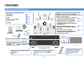 6
6
-
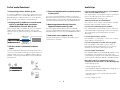 7
7
-
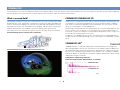 8
8
-
 9
9
-
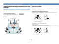 10
10
-
 11
11
-
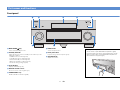 12
12
-
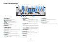 13
13
-
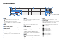 14
14
-
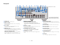 15
15
-
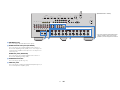 16
16
-
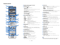 17
17
-
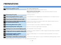 18
18
-
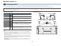 19
19
-
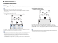 20
20
-
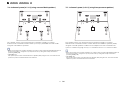 21
21
-
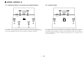 22
22
-
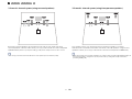 23
23
-
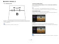 24
24
-
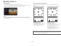 25
25
-
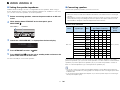 26
26
-
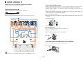 27
27
-
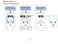 28
28
-
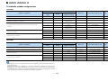 29
29
-
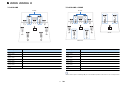 30
30
-
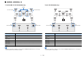 31
31
-
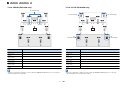 32
32
-
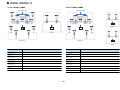 33
33
-
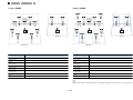 34
34
-
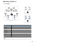 35
35
-
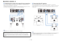 36
36
-
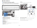 37
37
-
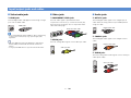 38
38
-
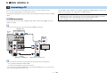 39
39
-
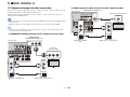 40
40
-
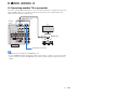 41
41
-
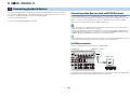 42
42
-
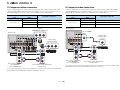 43
43
-
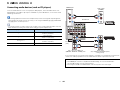 44
44
-
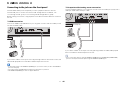 45
45
-
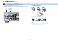 46
46
-
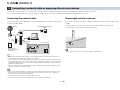 47
47
-
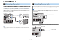 48
48
-
 49
49
-
 50
50
-
 51
51
-
 52
52
-
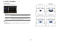 53
53
-
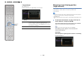 54
54
-
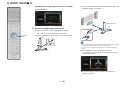 55
55
-
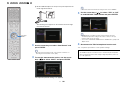 56
56
-
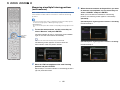 57
57
-
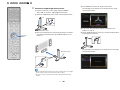 58
58
-
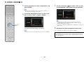 59
59
-
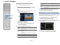 60
60
-
 61
61
-
 62
62
-
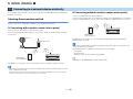 63
63
-
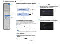 64
64
-
 65
65
-
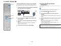 66
66
-
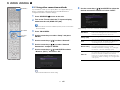 67
67
-
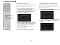 68
68
-
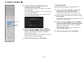 69
69
-
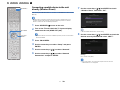 70
70
-
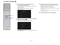 71
71
-
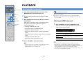 72
72
-
 73
73
-
 74
74
-
 75
75
-
 76
76
-
 77
77
-
 78
78
-
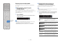 79
79
-
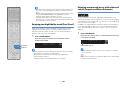 80
80
-
 81
81
-
 82
82
-
 83
83
-
 84
84
-
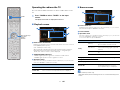 85
85
-
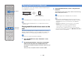 86
86
-
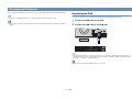 87
87
-
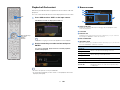 88
88
-
 89
89
-
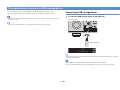 90
90
-
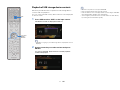 91
91
-
 92
92
-
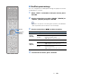 93
93
-
 94
94
-
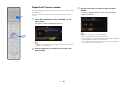 95
95
-
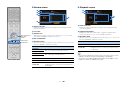 96
96
-
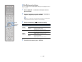 97
97
-
 98
98
-
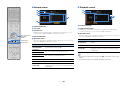 99
99
-
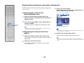 100
100
-
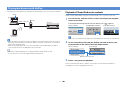 101
101
-
 102
102
-
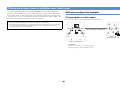 103
103
-
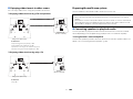 104
104
-
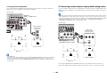 105
105
-
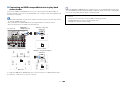 106
106
-
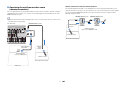 107
107
-
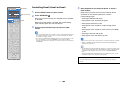 108
108
-
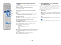 109
109
-
 110
110
-
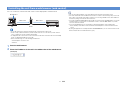 111
111
-
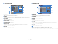 112
112
-
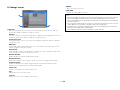 113
113
-
 114
114
-
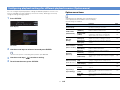 115
115
-
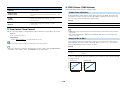 116
116
-
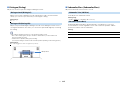 117
117
-
 118
118
-
 119
119
-
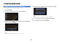 120
120
-
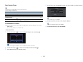 121
121
-
 122
122
-
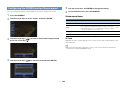 123
123
-
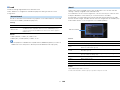 124
124
-
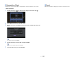 125
125
-
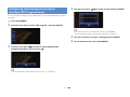 126
126
-
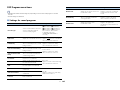 127
127
-
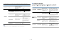 128
128
-
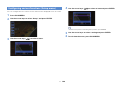 129
129
-
 130
130
-
 131
131
-
 132
132
-
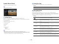 133
133
-
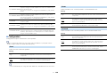 134
134
-
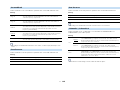 135
135
-
 136
136
-
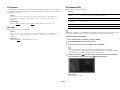 137
137
-
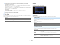 138
138
-
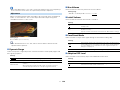 139
139
-
 140
140
-
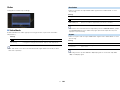 141
141
-
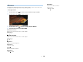 142
142
-
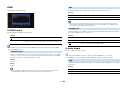 143
143
-
 144
144
-
 145
145
-
 146
146
-
 147
147
-
 148
148
-
 149
149
-
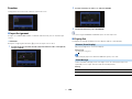 150
150
-
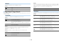 151
151
-
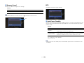 152
152
-
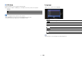 153
153
-
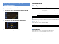 154
154
-
 155
155
-
 156
156
-
 157
157
-
 158
158
-
 159
159
-
 160
160
-
 161
161
-
 162
162
-
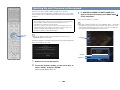 163
163
-
 164
164
-
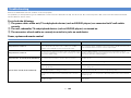 165
165
-
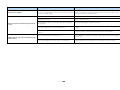 166
166
-
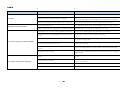 167
167
-
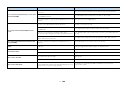 168
168
-
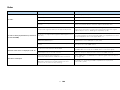 169
169
-
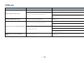 170
170
-
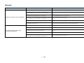 171
171
-
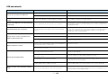 172
172
-
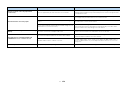 173
173
-
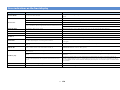 174
174
-
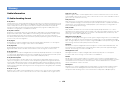 175
175
-
 176
176
-
 177
177
-
 178
178
-
 179
179
-
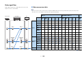 180
180
-
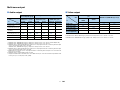 181
181
-
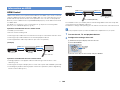 182
182
-
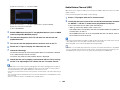 183
183
-
 184
184
-
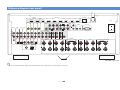 185
185
-
 186
186
-
 187
187
-
 188
188
-
 189
189
-
 190
190
-
 191
191
-
 192
192
-
 193
193


Yamaha AVENTAGE RX-A2050 El manual del propietario
- Categoría
- Receptores AV
- Tipo
- El manual del propietario
en otros idiomas
- français: Yamaha AVENTAGE RX-A2050 Le manuel du propriétaire
- italiano: Yamaha AVENTAGE RX-A2050 Manuale del proprietario
- English: Yamaha AVENTAGE RX-A2050 Owner's manual
- Deutsch: Yamaha AVENTAGE RX-A2050 Bedienungsanleitung
- русский: Yamaha AVENTAGE RX-A2050 Инструкция по применению
- Nederlands: Yamaha AVENTAGE RX-A2050 de handleiding
- dansk: Yamaha AVENTAGE RX-A2050 Brugervejledning
- svenska: Yamaha AVENTAGE RX-A2050 Bruksanvisning
- Türkçe: Yamaha AVENTAGE RX-A2050 El kitabı
- suomi: Yamaha AVENTAGE RX-A2050 Omistajan opas
Artículos relacionados
-
Yamaha RX-V3075 El manual del propietario
-
-
Yamaha Audio RX-V779 El manual del propietario
-
Yamaha RX-V471 El manual del propietario
-
Yamaha RX-V2067 El manual del propietario
-
-
-
-
-
Yamaha CX-A5100 El manual del propietario